

Page 1

Fig.1
Fig.2
2
J129
Page 2
I
UTILIZZAZIONE
La cappa è realizzata per essere utilizzata in versione aspirante ad evacuazione esterna o filtrante a ricircolo interno.
VERSIONE ASPIRANTE EVACUAZIONE ESTERNA
Per poter utilizzare questa funzione munirsi di un tubo flessibile da collegare al raccordo “A” fig1 che andrà successivamente fissato al soffitto.
VERSIONE FILTRANTE RICIRCOLO INTERNO
Quando non si ha la possibilità di evacuare l’aria all’esterno si utilizza
un filtro a carboni attivi.
L’aria viene depurata dal filtro e rimessa nell’ambiente attraverso le griglie presenti nei camini.
Per convertire la cappa da “Aspirante” a “Filtrante”,richiedere al venditore o alla ditta costruttrice il corredo di montaggio.
COLLEGAMENTO ELETTRICO
Prima di effettuare qualsiasi collegamento, assicurarsi che la tensione
di rete corrisponda alla tensione riportata sull’etichetta
caratteristiche,situata all’interno dell’apparecchio.
Si consiglia di delegare il collegamento elettrico ad un tecnico qualificato.
APPARECCHIOPROVVISTO DI SPINA
Allacciarlo ad una presa conforme alle norme vigenti.
La spina una volta inserita nella presa, deve trovarsi in un punto facilmente accessibile.
Se si intende allacciarlo direttamente alla rete elettrica togliere la spina
ed applicare un interrutore bipolare a norme con una distanza dei contatti in apertura non inferiore a 3mm.
APPARECCHIO SPROVVISTO DI SPINA
Applicare una spina a norme oppure un interruttore bipolare a norme
con una distanza dei contatti in apertura non inferiore a 3mm.
Si declina ogni responsabilità per inconvenienti derivati dall’inosservanza delle suddette disposizioni.
L’APPARECCHIO IN CLASSE 1 DEVE ESSERE
COLLEGATO AD UN IMPIANTO DI TERRA.
L’allacciamento deve essere eseguito come segue:
MARRONE = L (linea)
BLU = N (neutro)
GIALLO/VERDE = (terra)
L’APPARECCHIO IN CLASSE 2 NON DEVE ESSERE
COLLEGATO AD UN IMPIANTO DI TERRA.
Per gli apparecchi in classe 2 ,recanti sulla etichetta caratteristiche il
doppio quadrato,l’allacciamento deve essere eseguito come segue:
MARRONE = L (linea)
BLU = N (neutro)
ISTRUZIONI PER IL MONTAGGIO
La cappa pesa circa 35 kg quindi è importante fissarla al soffitto con un
montaggio accurato.
L’apparecchio messo in opera dovrà distare dal piano di cottura non
meno di 60 cm nel caso di fornelli elettrici, e 65 cm nel caso di fornelli a
gas.
Se le istruzioni di installazione del dispositivo di cottura a gas specificano una distanza maggiore,bisogna tenerne conto.
Per installare la cappa ad una giusta altezza bisogna prima di tutto
regolare la lunghezza “L”della struttura telescopica.
Per fare questo procedere nel seguente modo:
1) misurare l’altezza “H” tra il soffitto ed il pavimento
2) stabilire la distanza desiderata “D”tra il pavimento e la cappa
3) misurare l’altezza “X”della cappa
4) si otterrà “L”applicando la seguente formula:
Regolata la lunghezza della struttura telescopica fissare i due pezzi
fig2.
MANUTENZIONE
Disinserire l’apparecchio dalla rete elettrica prima di ef fettuare qualsiasi operazione di manutenzione.
Il buon funzionamento della cappa è condizionato dall’assiduità con cui
vengono effettuate le operazioni di manutenzione in modo particolare
delle griglie alluminio e del filtro al carbone attivo.
Le griglie hanno il compito di trattenere le particelle grasse o solide in
sospensione nell’aria.
Pertanto sono soggette ad intasarsi in tempi variabili a secondo dell’uso
e del tipo di cucina .
Le griglie in alluminio stirato vanno lavate a mano o in lavastoviglie
,lasciandole asciugare prima del montaggio.
In caso di inadempienza delle istruzioni di lavaggio vi è la possibilità
di incendio.
Il filtro al carbone attivo ,presente solo nella versione filtrante ,ha la
funzione di trattenere gli odori e depurare l’aria.
La saturazione del filtro carbone si verifica dopo un uso più o meno
prolungato a secondo del tipo di cucina e della regolarità della pulizia
delle griglie alluminio.
Sostituire il filtro carbone,quando viene segnalato dalla spia led “F” (versione elettronica).
In ogni caso quando non è segnalato, sostituire la cartuccia al massimo
ogni 4 mesi.
PULIZIA DELLA CAPPA
Per la pulizia esterna della cappa usare un panno inumidito con alcool
denaturato o detersivi liquidi neutri.Evitare l’uso di prodotti contenenti
abrasivi.
Pulire frequentemente tutti i depositi sul ventilatore e le altre superfici
con i medesimi prodotti.
ATTENZIONE: ISTRUZIONI PER LA SICUREZZA
L’evacuazione non deve essere convogliata ne in un camino funzionante per lo scarico dei fumi o di gas combustibili, ne in un condotto utilizzato come canna fumaria per ambienti in cui sono installati fonti con fuochi aperti.Per incanalare i vapori ,devono essere rispettate le disposizioni delle autorità competenti.In caso di funzionamento contemporaneo
della cappa con evacuazione esterna e di altre fonti necessitanti di canna fumaria, ci si deve accertare che vi sia sufficiente apporto d’aria.
1) Non cercate di controllare i filtri con la cappa in azione.
2) Non ostruite le uscite di scarico dell’aria
3) Non toccare le lampadine o il copri-lampada dopo il protratto uso
dell’apparecchio
4) E ‘‘‘vietato cuocere cibi alla fiamma sotto la cappa.
5) Evitare la fiamma libera, perché dannosa per i filtri e pericolosa per
gli incendi.
6) Controllare costantemente la frittura per evitare che l’olio surriscaldato prenda fuoco.
7) Prima di effettuare manutenzioni disinserire la cappa dalla rete elettrica.
8) Si declina ogni responsabilità per eventuali danni provacati dall’inosservanza delle suddette avvertenze.
L=H-(D+X) fig1
3J129
Page 3

DD
EINSATZMÖGLICHKEIT
Diese Dunstabzugshaube ist so konzipiert, dass sie sowohl im Abluftbetrieb (Ansaugfunktion), als auch im Umluftbetrieb (Filterfunktion) eingesetzt werden kann.
ABLUFTBETRIEB MIT ANSAUGFUNKTION
Zum Einsatz in dieser Version beschaffen Sie sich bitte ein Flexrohr, das
an den Anschluss „A“ (Abb.1) anzuschließen ist und anschließend an
der Decke befestigt werden muss.
ACHTUNG:
Bei gleichzeitigem Betrieb der Dunstabzugshaube im Abluftbetrieb
und Feuerstätten darf im Aufstellraum der Feuerstätte der Unterdruck nicht höher als 4 Pa(4x10 –5 bar) sein.
UMLUFTBETRIEB MIT FILTERFUNKTION
Besteht keine Möglichkeit, die Luft ins Freie abzuleiten, muss ein Aktivkohlefilter eingesetzt werden.
Die Luft wird gefiltert und über die im Schacht befindlichen Gitter gereinigt wieder in den Raum zurückgeführt.
Zum Umrüsten der Dunstabzugshaube von „Abluftbetrieb“ auf „Umluftbetrieb“ fordern Sie bitte bei Ihrem Fachhändler oder beim Gerätehersteller den hierzu erforderlichen Montagesatz an.
ELEKTRISCHER ANSCHLUSS
Vor dem Anschluss muss sichergestellt werden, dass die Netzspannung
den auf dem Typenschild (im Geräteinnern) angegebenen Werten entspricht.
Bitte lassen Sie den Elektroanschluss durch Fachpersonal durchführen.
MIT STECKER BESTÜCKTES GERÄT
Schließen Sie das Gerät an eine den einschlägigen Bestimmungen entsprechende Steckdose an. Der angeschlossene Stecker sollte sich an
einer leicht zugänglichen Stelle befinden.
Sollte das Gerät direkt an das Stromnetz angeschlossen werden, ist der
Stecker zu entfernen, und eine T rennvorrichtung mittels eines vorschriftsmäßigen zweipoligen Schalters mit einer Kontaktöffnung, die 3 mm nicht
unterschreiten darf, zu installieren.
GERÄT OHNE STECKER
Versehen Sie das Gerät mit einem vorschriftsmäßigen Stecker oder einem zweipoligen Schalter mit einer Kontaktöffnung, die 3 mm nicht unterschreiten darf. Jegliche Haftung für Schäden, die durch Nichteinhaltung obiger Anweisungen auftreten, wird zurückgewiesen.
1) Messen Sie die Höhe „H“ d.h. den Abstand zwischen Decke und
Fußboden.
2) Bestimmen Sie den gewünschten Abstand „D“ zwischen Fußboden
und Dunstabzugshaube.
3) Messen Sie die Höhe „X“ der Dunstabzugshaube.
4) Sie erhalten den Wert „L“ mittels folgender Formel:
L=H-(D+X) Abb.1
Wurde der T eleskopschacht auf die korrekte Länge eingestellt, sind beide Teile (Abb.2) zu befestigen.
WARTUNG UNF PFLEGE
Vor jeder Wartung und Pflege muss das Gerät vom Stromnetz getrennt werden.
Nur eine regelmäßige Wartung und Pflege garantiert eine gute Leistung
des Gerätes. Besondere Pflege ist den Alugittern und dem Aktivkohlefilter zuzuwenden.
Die Gitter dienen zur Aufnahme der in der Luft schwebenden Fettpartikel.
Sie sind der Verschmutzung besonders ausgesetzt und sollten, je nach
Gebrauch und Kochgewohnheiten in mehr oder weniger langen Zeitabschnitten gereinigt werden.
Die Gitter aus gezogenem Aluminium sind von Hand oder im Geschirr spüler zu reinigen. Lassen Sie sie vor erneuter Montage gut trocknen.
Durch Nichtbeachtung dieser Hinweise kann Brand verursacht wer den.
Der Aktivkohlefilter (erforderlich nur bei Umluftbetrieb) dient zur Aufnahme der Gerüche und Reinigung der Luft.
Die Sättigung dieses Filters hängt vom Gebrauch, der Art der gekochten
Speisen und der mehr oder weniger häufigen Reinigung der Metallfilter ab.
Er muss ausgetauscht werden, wenn durch die Kontrollleuchte „F“ (elektronische Version) die Sättigung desselben signalisiert wird.
Auf jeden Fall jedoch sollte er alle 4 Monate ausgetauscht werden, auch
wenn kein Sättigungssignal aufleuchtet.
REINIGUNG
Zur Reinigung der äußeren T eile verwenden Sie bitte nur ein mit denaturiertem Alkohol oder einem milden Spülmittel angefeuchtetes T uch. V er meiden Sie Reiniger, die Scheuermittel enthalten.
Schmutzablagerungen auf dem Gebläse sind öfter zu entfernen, verwenden Sie auch hierzu, wie auch für die übrigen Oberflächen, dieselben milden Reinigungsmittel.
GERÄTE DER KLASSE 1 MÜSSEN AN EINEN
ERDLEITER ANGESCHLOSSEN WERDEN.
Der Anschluss ist wie folgt vorzunehmen:
BRAUN = L (Leitungsnetz)
BLAU = N (Nullleiter)
GELB/GRÜN =
GERÄTE DER KLASSE 2 ERFORDERN KEINEN ERDANSCHLUSS.
Geräte der Klasse 2, auf deren Typenschild das Symbol eines Doppelvierecks abgebildet ist, sind wie folgt anzuschließen:
BRAUN = L (Leitungsnetz)
BLAU = N (Nullleiter)
MONTAGEANLEITUNG
Die Dunstabzugshaube wiegt ca. 35 kg, die Befestigung an der Decke
erfordert demnach größte Sorgfalt.
Bei fertig installiertem Gerät muss der Abstand über dem Kochfeld mindestens 60 cm betragen, wenn es sich um elektrische Kochfelder handelt, und mindestens 65 cm, wenn es sich um Gas-Kochfelder handelt.
Sollten die Installationsanweisungen der Gas-Kochvorrichtungen einen größeren Abstand vorschreiben, ist dieser zu beachten.
Um bei der Installation auch die richtige Höhe zu ermitteln, ist in erster
Linie die Länge „L“ des Teleskopschachtes zu regulieren.
Zur Ermittlung dieser verfahren Sie wie folgt:
(Erde)
4
ACHTUNG: SICHERHEITSANWEISUNGEN
Die Abluft darf weder in einen Schornstein, der bereits zur Ableitung von
Verbrennungsgasen oder Rauch verwendet wird, noch in einen Abluftschacht, der für Räume mit offenen Feuerstätten dient, geleitet werden. Hinsichtlich der Ableitung der Kochdünste sind die behördlichen
Vorschriften zu beachten. Bei gleichzeitigem Betrieb einer Dunstabzugshaube im Abluftbetrieb und anderer raumluft- und kaminabhängigen
Feuerstätten muss sichergestellt werden, dass eine ausreichende Belüftung gewährleistet ist.
1) Versuchen Sie nicht die Filter zu überprüfen, wenn sich die Dunstabzugshaube in Betrieb befindet.
2) Die Belüftungsöffnungen dürfen nicht abgedeckt werden.
3) Berühren Sie weder die Lampen noch die Lampenabdeckung, wenn
das Gerät schon längere Zeit eingeschaltet ist.
4) Flambieren Sie nie unter der Dunstabzugshaube, dies ist gefährlich.
5) Vermeiden Sie offene Flammen, diese schaden den Filtern und können einen Brand auslösen.
6) Speisefett kann in wenigen Minuten überhitzen und sich selbst entzünden. Lassen Sie demnach Pfannen und Fritteusen niemals unbeaufsichtigt.
7) Schalten Sie die Dunstabzugshaube vor der Reinigung vom Stromnetz ab.
8) Jegliche Haftung für Schäden, die durch Nichteinhaltung obiger Anweisungen auftreten, wird zurückgewiesen.
J129
Page 4
GB
GB
USE
The hood is designed to be used either to filter and re-circulate air or in
a ducted vented mode.
OUTDOOR VENTED INSTALLATION
To use the hood in the vented mode, you need to connect a flexible
pipe to the connector “A” (fig. 1), which should then be fastened to
the ceiling.
VENTLESS FILTERING INSTALLATION
When the air cannot be vented to the outside, the hood can be fitted with
an activated carbon filter.
The air is purified by the filter and re-circulated into the room via the
grids on the flues.
To switch from “Vented” to “Ventless” operation, contact your retailer or
the manufacturer for the relevant assembly kit.
ELECTRICAL CONNECTION
Before making any electrical connections, make sure that the voltage of
the electrical mains corresponds with the value indicated on the appliance
rating sticker.
It is highly recommended that the electrical connection be made by a
qualified electrician.
APPLIANCE FITTED WITH A PLUG
Insert the plug into a socket that complies with the applicable norms in
force.
Once plugged into the socket, the plug must be easily accessible.
If you intend to connect the hood directly to the electrical mains, remove
the plug and add a standard bipolar switch with a minimum contact
opening of 3mm.
APPLIANCE NOT FITTED WITH A PLUG
Fit a standard plug or a standard bipolar switch compliant with the
applicable norms in force, with a minimum contact opening of 3mm.
The manufacturer will not be held responsible for any problems arising
from failure to comply with the above instructions.
CLASS 1 APPLIANCES MUST BE EARTHED
The connection must be made as follows:
BROWN = L (current)
BLUE = N (neutral)
YELLOW/GREEN=
CLASS 2 APPLIANCES DO NOT HAVE TO BE EARTHED
Class 2 appliances labelled with a rating sticker featuring the symbol in
the form of a double square must be connected as follows:
BROWN = L (current)
BLUE = N (neutral)
ASSEMBLY INSTRUCTIONS
The hood weighs approximately 35 kg and should therefore be fastened
securely to the ceiling.
The appliance should be installed at least 60 cm above an electric hob
and at least 65 cm above gas hobs.
If the appliance is installed above a gas cooking device with
installation instructions specifying a greater clearance, you must take
this into account.
To install the hood at the correct height, first adjust the length “L” of the
telescopic flue.
To do so, proceed as follows:
1) measure the height “H” from the ceiling to the floor
2) fix the desired distance “D” between the hood and the floor
3) measure the height “X” of the hood
4) to find out “L”, apply the following formula:
(earth)
Once you have adjusted the length of the telescopic flue, fasten the two
units (fig. 2)
MAINTENANCE
Disconnect the appliance from the electrical power supply before
performing any maintenance operations on the same.
The correct operation of the hood is directly related to how often it is
cleaned and serviced, especially the aluminium grids and the activated
carbon filter.
The grids trap any grease particles and solids suspended in the air.
They therefore tend to clog over time, depending on how often the hood
is used and on the type of cooker installed.
The forged aluminium grids should be washed by hand or in your
dishwasher, and allowed to dry thoroughly before remounting.
Failure to comply with the washing instructions could result in a fire
hazard.
The activated carbon filter is only used by the ventless, filtering version,
and is designed to trap odours and clean the air.
The carbon filter is saturated after a varying amount of time depending
on the type of cooker used and on how regularly the aluminium grids
are cleaned.
Replace the carbon filter when prompted to do so by the LED indicator
light “F” (electronic version).
In any case, in the absence of such prompting, the cartridge must be
replaced at least once every four months.
CLEANING THE HOOD
Wipe the exterior of the hood with a cloth dampened with denatured
alcohol or mild liquid detergents. Avoid using abrasive products.
Wipe off all deposits from the fan and other hood surfaces frequently,
using the above products.
ATTENTION: SAFETY WARNINGS
The cooking vapours must not be vented to the outside along a flue
used for venting combustion fumes or gases, nor along a duct used as
a flue for rooms in which open flame appliances are installed. The vapour
ducting installation must comply with the applicable norms in force. If
the hood is being used in the outdoor vented mode where other vented
fuel-burning appliances are installed, you must ensure there is a sufficient
supply of air to the room.
1) Do not attempt to check the filters when the hood is in operation.
2) Do not obstruct any air outlets.
3) Do not touch the lamps or lamp diffusers after prolonged use of the
hood.
4) Do not flambé food underneath the hood.
5) Avoid leaving an open flame uncovered, as it could damage the
filters and increase the risk of fire.
6) Never leave frying food unattended to prevent hot oil from catching
fire.
7) Disconnect the hood from the electrical mains before performing any
maintenance operations.
8) The manufacturer will not be held responsible for any damage
caused due to failure to comply with the above warnings.
L=H-(D+X) fig. 1
5J129
Page 5

E
USO
La campana se fabrica para ser utilizada en la versión aspirante con
evacuación externa o filtrante con recirculación interna.
VERSIÓN ASPIRANTE CON EVACUACIÓN EXTERNA
Para poder utilizar esta función se debe contar con un tubo flexible que se
va a conectar a la unión “A” fig.1 que posteriormente se fijará al techo.
VERSIÓN FILTRANTE CON RECIRCULACIÓN INTERNA
Cuando no existe la posibilidad de evacuar el aire hacia el exterior, se
utiliza un filtro de carbón activo.
El aire es depurado por el filtro y se vuelve a introducir en el ambiente a
través de las rejillas presentes en las chimeneas.
Para convertir la campana de “Aspirante” a “Filtrante”, solicite al vendedor o a la empresa fabricante el equipo de montaje.
CONEXIÓN ELÉCTRICA
Antes de efectuar cualquier conexión, verifique que la tensión de la red
se corresponda con la tensión que se encuentra en la etiqueta de características ubicada en el interior del aparato.
Es aconsejable delegar la conexión eléctrica a un técnico especializado.
APARATO PROVISTO DE ENCHUFE
Conéctelo a una toma de corriente conforme con las normas vigentes.
El enchufe una vez introducido en la toma, se debe encontrar en un
punto fácilmente accesible.
Si se pretende conectarlo directamente a la red eléctrica, quite el enchufe y aplique un interruptor bipolar conforme con las normas y con
una distancia entre los contactos de 3 mm. o mayor.
APARATO NO PROVISTO DE ENCHUFE
Aplique un enchufe conforme con las normas o un interruptor bipolar
también conforme con las normas y con una distancia entre los contactos de 3mm. o mayor.
Se declina toda responsabilidad por los inconvenientes que se puedan
producir derivados de la falta de respeto de las mencionadas disposiciones.
EL APARATO DE CLASE 1 SE DEBE CONECTAR A TIERRA.
La conexión se debe realizar del siguiente modo:
MARRÓN = L (línea)
AZUL = N (neutro)
AMARILLO/VERDE=
EL APARATO DE CLASE 2 NO SE DEBE CONECTAR A TIERRA.
Para los aparatos de clase 2, que posean en la etiqueta de características el doble cuadrado, la conexión se debe realizar del siguiente modo:
MARRÓN = L (línea)
AZUL = N (neutro)
INSTRUCCIONES PARA EL MONTAJE
La campana pesa aproximadamente 35 kg., por lo tanto, es importante
fijarla al techo con un montaje cuidadoso.
Una vez instalada, la distancia entre el aparato y la superficie de cocción no debe ser inferior a 60 cm. en el caso de quemadores eléctricos
y a 65 cm. en el caso de quemadores a gas.
Si las instrucciones de instalación del dispositivo de cocción a gas
especifican una distancia mayor, no hay que ignorarlo.
Para instalar la campana a una altura justa, es necesario, antes que
nada, regular la longitud “L” de la estructura telescópica.
Para hacerlo, proceda del siguiente modo:
1) mida la altura “H” entre el techo y el piso.
2) establezca la distancia deseada “D” entre el piso y la campana
3) mida la altura “X” de la campana
4) se obtendrá “L” aplicando la siguiente fórmula:
(tierra)
Una vez regulada la longitud de la estructura telescópica, fije las dos
piezas (fig. 2)
MANTENIMIENTO
Desconecte el aparato de la red eléctrica antes de efectuar cualquier operación de mantenimiento.
El buen funcionamiento de la campana depende de la asiduidad con
que se efectúan las operaciones de mantenimiento, en particular de las
rejillas de aluminio y del filtro de carbón activo.
Las rejillas tienen la función de retener las partículas grasas o sólidas
que se encuentran en suspensión en el aire.
Por lo tanto, se pueden atascar en tiempos variables según el uso y el
tipo de cocina.
Las rejillas de aluminio estirado se deben lavar a mano o en lavavajilla
dejándolas secar antes de su montaje.
En caso de incumplimiento de las instrucciones de lavado, existe la
posibilidad de que se produzca un incendio.
El filtro de carbón activo, presente sólo en la versión filtrante, tiene la
función de retener los olores y depurar el aire.
La saturación del filtro de carbón se produce después de un uso más o
menos prolongado según el tipo de cocina y la regularidad de la limpieza de las rejillas de aluminio.
Sustituya el filtro de carbón cuando lo indique la luz testigo “F” (versión
electrónica).
De todos modos, aún cuando no lo indique, sustituya el cartucho cada
4 meses como máximo.
LIMPIEZA DE LA CAMP ANA
Para la limpieza externa de la campana use un paño humedecido con
alcohol desnaturalizado o con detergentes líquidos neutros. Evite el uso
de productos que contengan abrasivos.
Limpie frecuentemente todos los depósitos que se forman en el ventilador y en otras superficies con los mismos productos.
ATENCIÓN: INSTRUCCIONES PARA LA SEGURIDAD
En ambientes en los cuales hay instaladas fuentes con fuegos abiertos,
la evacuación no debe ser enviada a una chimenea para la descarga
de humos o de gases combustibles, ni hacia un conducto utilizado como
conducto de humos. Para canalizar los vapores, se deben respetar las
disposiciones de las autoridades competentes. En caso de funcionamiento simultáneo de la campana con evacuación externa y de otras
fuentes que necesitan conducto de humos, se debe verificar que haya
el suficiente aporte de aire.
1) No intente controlar los filtros con la campana en funcionamiento.
2) No obstruya las salidas de aire.
3) No toque las bombillas o el cubrelámpara después de un
prolongado uso del aparato.
4) Está prohibido cocinar alimentos con llama directa debajo de la
campana.
5) Evite la llama libre ya que daña los filtros y puede producir incendios.
6) Controle constantemente la fritura para evitar que el aceite
sobrecalentado se prenda fuego.
7) Antes de efectuar operaciones de mantenimiento, desconecte la
campana de la red eléctrica.
8) Se declina toda responsabilidad por los posibles daños que se
puedan producir derivados de la falta de respeto de las mencionadas
advertencias.
L=H-(D+X) fig1
6
J129
Page 6
F
UTILISATION
Cette hotte est conçue pour fonctionnement en version aspirante à évacuation extérieure ou filtrante à recyclage intérieur.
VERSION ASPIRANTE A EVACUATION EXTERIEURE
Pour utiliser votre hotte dans cette version, il vous faut relier un tuyau
flexible au raccord “A” fig. 1 que vous fixerez ensuite au plafond.
VERSION FILTRANTE A RECYCLAGE
Quand il n’est pas possible d’évacuer l’air à l’extérieur, il faut utiliser un
filtre à charbon actif.
L’air épuré par le filtre est renvoyé dans la pièce à travers les grilles fixées
sur les cheminées.
Pour transformer la hotte de la version “Aspirante” à la version “Filtrante”,
demandez à votre revendeur ou au fabricant le matériel nécessaire au
montage.
RACCORDEMENT ELECTRIQUE
Avant d’effectuer le moindre raccordement électrique, assurez-vous que
la tension de réseau correspond bien à la tension indiquée sur l’étiquette
signalétique située à l’intérieur de l’appareil.
Pour le raccordement électrique, nous vous conseillons de faire appel à
un professionnel du secteur.
APPAREIL MUNI D’UNE FICHE
Raccordez-le à une prise conforme aux normes applicables en la matière.
Une fois qu’elle été insérée dans la prise, la fiche doit pouvoir être facilement accessible.
En cas de branchement direct au réseau électrique, enlevez la fiche et
montez un interrupteur bipolaire réglementaire ayant une distance entre les contacts d’ouverture d’au moins 3 mm.
APPAREIL DEPOURVU DE FICHE
Montez une fiche réglementaire ou bien un interrupteur bipolaire réglementaire ayant une distance entre les contacts d’ouverture d’au moins
3 mm
Nous déclinons toute responsabilité en cas d’inconvénients dérivant de
l’inobservation de ces consignes.
L’APPAREIL EN CLASSE 1 DOIT ETRE RACCORDE A LA TERRE
Le raccordement doit être effectué comme suit :
MARRON = L (ligne)
BLEU = N (neutre)
JAUNE/VERT =
L’APPAREIL EN CLASSE 2 NE DOIT PAS ETRE RACCORDE A LA TERRE
Pour les appareils en classe 2 qui ont un double carré sur l’étiquette
signalétique, la connexion doit être effectuée comme suit :
MARRON = L (ligne)
BLEU = N (neutre)
INSTRUCTIONS DE MONTAGE
La hotte pèse environ 35 kg, il faut par conséquent faire très attention à
son montage et bien la fixer au plafond.
Une fois installé au-dessus du plan de cuisson, l’appareil devra se trouver à au moins 60 cm de distance en cas de foyers électriques et 65 cm
en cas de foyers à gaz.
Si la notice d’installation des foyers à gaz préconise une distance
plus grande, veuillez en tenir compte.
Pour installer la hotte à la bonne hauteur, il faut avant tout régler la longueur «L» de la structure télescopique.
Procédez comme suit :
1) mesurez la hauteur “H” entre le plafond et le sol
2) décidez la distance souhaitée “D” entre le sol et la hotte
3) mesurez la hauteur “X” de la hotte
4) vous obtiendrez “L” en appliquant la formule suivante :
(terre)
Une fois que la longueur de la structure télescopique est réglée, fixez les
deux parties (fig2)
ENTRETIEN
Coupez l’alimentation électrique de l’appareil avant de procéder à
toute opération d’entretien.
Le bon fonctionnement de la hotte dépend de la fréquence d’entretien
des grilles en aluminium notamment et du filtre à charbon actif.
Les grilles ont pour tâche de bloquer les particules grasses ou solides
en suspension dans l’air.
Elles ont donc tendance à se boucher plus ou moins rapidement selon
la fréquence d’utilisation de la hotte et le genre de cuisine.
Les grilles en aluminium forgé doivent être lavées à la main ou en
lave-vaisselle et mises sécher avant d’être remontées.
L’inobservation des instructions de lavage peut entraîner des risques
d’incendie.
Le filtre à charbon actif, monté uniquement dans la version à recy-
clage (filtrante) a pour rôle d’éliminer les odeurs et d’épurer l’air.
Le filtre à charbon est saturé après un usage plus ou moins prolongé
selon le genre de cuisine et la régularité avec laquelle les grilles aluminium sont nettoyées.
Remplacez le filtre à charbon quand le led témoin “F” le signale (version
électronique).
Il faut de toute façon remplacer la cartouche au moins tous les 4 mois.
NETTOYAGE DE LA HOTTE
Pour le nettoyage extérieur de la hotte, utilisez un chiffon imbibé d’alcool
dénaturé ou d’un détergent liquide neutre. Les produits contenant des
substances abrasives sont à éviter.
Nettoyez fréquemment les dépôts sur le ventilateur et les autres surfaces en utilisant les mêmes produits.
ATTENTION : INSTRUCTIONS DE SECURITE
L’air évacué ne doit pas être acheminé dans un conduit de cheminée
servant à l’évacuation de fumée ou de gaz brûlés ni dans un conduit de
cheminée desservant des locaux où sont installés des foyers à feu ouvert.
Pour canaliser les vapeurs, respectez les dispositions des autorités compétentes. En cas de fonctionnement conjoint d’une hotte à évacuation
extérieure et d’autres foyers nécessitant d’un conduit de cheminée, assurez-vous qu’il y ait un apport d’air suffisant.
1) N’essayez pas de contrôler l’état des filtres quand la hotte est en
marche.
2) Ne bouchez pas les sorties d’évacuation de l’air
3) Ne touchez pas aux ampoules ou au cache lampe après un usage
prolongé de l’appareil
4) Il est interdit de flamber des aliments sous la hotte.
5) Evitez de laisser des flammes libres, elles sont dangereuses pour
les filtres et pour les risques d’incendie.
6) Surveillez constamment la friture pour éviter que l’huile surchauffée
prenne feu.
7) Avant de procéder à toute opération d’entretien, coupez l’alimentation électrique de la hotte.
8) Nous déclinons toute responsabilité en cas d’inconvénients dérivant
de l’inobservation de ces consignes.
L=H-(D+X) fig1
7J129
Page 7
NL
GEBRUIK
De kap is uitgevoerd voor gebruik in de versies met afzuiging naar buiten
of filtrerende circulatie binnen.
VERSIE AFZUIGING NAAR BUITEN
Voor gebruik van de kap in deze functie moet u een flexibile buis verbinden aan het aansluitstuk “A” afb1 die vervolgens aan het plafond wordt
bevestigd.
VERSIE FILTRERENDE CIRCULATIE BINNEN
Als er geen mogelijkheid bestaat de lucht naar buiten af te voeren moet
u een actieve koolfilter gebruiken.
De lucht wordt door de filter gezuiverd en weer in het vertrek losgelaten
door de roosters die zich in de rookkanalen bevinden.
Voor het veranderen van de kap van “Afzuigend” naar “Filtrerend” moet
u uw handelaar of de fabriek vragen om de montage-kit.
ELEKTRISCHE AANSLUITING
Voordat u de elektrische aansluiting gaat uitvoeren moet u controleren
of de spanning van uw net correspondeert met de spanning die is
aangegeven op het typeplaatje dat zich binnenin het apparaat bevindt.
Wij raden aan de elektrische aansluiting door een bevoegde installateur
te laten uitvoeren.
APPARAAT VOORZIEN VAN STEKKER
Steek hem in een stopcontact dat voldoet aan de geldende normen.
De stekker, eenmaal in het stopcontact gestoken, moet zich op een
gemakkelijk te bereiken punt bevinden.
Als u het apparaat rechtstreeks aan uw net wilt aansluiten, dan moet u
de stekker verwijderen en een tweepolige schakelaar aanbrengen die
aan de normen voldoet met een afstand tussen de contacten van
minstens 3mm.
APP ARAAT ZONDER STEKKER
Breng een stekker aan die aan de normen voldoet of een tweepolige
schakelaar volgens de normen met een afstand tussen de contacten
van minstens a 3mm.
De fabrikant is niet aansprakelijk voor schade of storingen die te wijten
zijn aan het niet in acht nemen van bovengenoemde richtlijnen.
HET APPARAAT IN KLASSE I MOET WORDEN GEAARD.
De aansluiting moet als volgt worden uitgevoerd:
BRUIN = L (lijn)
BLAUW = N (neutraal)
GEEL/GROEN = (aarde)
HET APPARAAT IN KLASSE 2 HOEFT NIET GEAARD TE WORDEN.
Voor de apparaten in klasse 2, op het typeplaatje aangegeven met dubbel
vierkantje, moet de aansluiting op de volgende manier worden uitgevoerd:
BRUIN = L (lijn)
BLAUW = N (neutraal)
INSTRUCTIES VOOR HET MONTEREN
De kap weegt ongeveer 35 kg en moet dus met zorg aan het plafond
worden gemonteerd.
De afstand tussen kap en kookplaat moet minstens 60 cm zijn bij elektrische kookplaten en 65 cm bij gasbranders.
Als de installatie-instructies van het gasfornuis een grotere afstand
aangeven moet u zich daaraan houden.
Voor het installeren van de kap op de juiste hoogte moet u eerst de
lengte “L” van de telescopische structuur regelen.
Hiervoor gaat u als volgt te werk:
1) meet de hoogte “H” tussen plafond en vloer
2) stel de gewenste afstand “D” tussen vloer en kap vast
3) meet de hoogte “X” van de kap
4) u krijgt “L” met de volgende formule:
Nadat u de lengte van de telescopische structuur heeft geregeld bevestigt
u de twee stukken aan elkaar (afb2)
ONDERHOUD
Sluit altijd eerst de stroom af voordat u overgaat tot onderhoud.
Het goed functioneren van de kap hangt af van regelmatig onderhoud
vooral wat betreft de aluminium roosters en de actieve kookfilter.
De roosters houden de vet en vuil deeltjes vast die in de lucht hangen.
Zij worden dus periodiek verstopt, variërend naar gelang het gebruik
dat u van de kap maakt en het soort koken.
De roosters van geperst aluminium worden met de hand gewassen of
in de vaatwasser, en goed gedroogd voordat ze weer worden
gemonteerd.
Bij niet in acht nemen van de wasinstructies kan er brandgevaar
ontstaan.
De actieve koolfilter, die alleen aanwezig is bij de filtrerende versie,
dient voor het vasthouden van de kookgeuren en het reinigen van de
lucht.
De koolfilter wordt na kortere of langere tijd verzadigd, dit hangt af van
het soort koken en de regelmaat waarmee de aluminium roosters worden gereinigd.
Vervang de koolfilter als dit wordt aangegeven door het LED
controlelampje “F” (elektronische versie).
Als het niet wordt aangegeven moet hij minstens om de 4 maanden
worden vervangen.
HET REINIGEN VAN DE KAP
Voor het reinigen van de buitenkant van de kap gebruikt u een met spiritus
bevochtigde doek of vloeibaar schoonmaakmiddeli. Gebruik nooit
schuurmiddeln.
Reinig met dezelfde producten het vuil op de ventilator en de andere
oppervlakken.
ATTENTIE: INSTRUCTIES VOOR DE BEVEILIGING
De afvoer mag niet worden geleid door een schoorsteen die wordt
gebruikt voor het afvoeren van rook of brandbaare gassen, noch door
een leiding die als rookkanaal wordt gebruikt in vertrekken waar een
open haard is geïnstalleerd. Voor het afvoeren van de walmen moeten
de richtlijnen van de betreffende autoriteiten in acht worden genomen.
In het geval van tegelijkertijd functioneren van de kap met afzuiging naar
buiten en andere bronnen die een rookkanaal nodig hebben moet u er
voor zorgen dat het vertrek voldoende van lucht wordt voorzien.
1) Controleer de filters niet als de kap in werking is.
2) Blokkeer niet de uitgang van de luchtafvoer
3) Raak het lampje of het lampschermpje niet aan als het apparaat
lang in werking is geweest
4) Het is verboden onder de kap te flamberen.
5) Vermijd een open vlam aangezien die de filters kan beschadigen en
brandgevaar op kan leveren.
6) Bij frituur moet constant worden opgelet dat de olie niet te heet wordt
en vlam vat.
7) Sluit altijd eerst de stroom af voordat u overgaat tot onderhoud.
8) De fabrikant kan niet aansprakelijk worden gesteld voor eventuele
schade die is veroorzaakt door het niet in acht nemen van
bovenstaande aanwijzingen.
L=H-(D+X) afb1
8
J129
Page 8

RU
НАЗНАЧЕНИЕ
Кухонная вытяжка может быть представлена в версии для
дымоудаления с выводом воздуха в атмосферу или для
воздухоочистки в замкнутой циркуляции.
МОДЕЛЬ ВЫТЯЖКИ С ВЫВОДОМ ВОЗДУХА В АТМОСФЕРУ
Для использования данной функции необходимо подсоединить
гибкую трубу к патрубку «А» рис. 1, который затем прикрепляется
к потолку.
МОДЕЛЬ ДЛЯ ВОЗДУХООЧИСТКИ
В ЗАМКНУТОЙ ЦИРКУЛЯЦИИ
Если вывод вытяжки в атмосферу невозможен, использовать
фильтр с активированным углем.
Воздух очищается фильтром и возвращается в помещение через
решетки вытяжки.
Для того чтобы из вытяжки с выводом воздуха в атмосферу сделать
углевой воздухоочиститель, необходимо заказать у продавца или
на заводе-производителе крепежный комплект.
ЭЛЕКТРОПРОВОДКА
Перед осуществлением каких-либо электрических соединений
необходимо проверить, чтобы напряжение в сети соответствовало
значению, указанному на заводской табличке, расположенной
внутри вытяжки.
Рекомендуется поручить выполнение электропроводки
квалифицированному технику.
ВЫТЯЖКА, ОСНАЩЕННАЯ ШТЕПСЕЛЬНЫМ РАЗЪЕМОМ
Вставить штепсельный разъем в розетку, отвечающую
требованиям действующих нормативов.
Розетка, в которую вставляется штепсельный разъем вытяжки,
должна располагаться в легко доступном месте.
При подсоединении вытяжки непосредственно к сети
электропитания необходимо снять штепсельный разъем и
установить двухконтактный выключатель, отвечающий
требованиям действующих нормативов, с расстоянием между
разъединяющими контактами не менее 3 мм.
ВЫТЯЖКА БЕЗ ШТЕПСЕЛЬНОГО РАЗЪЕМА
Установить штепсельный разъем, отвечающий требованиям
действующих нормативов, или двухконтактный выключатель,
отвечающий требованиям действующих нормативов, с расстоянием
между разъединяющими контактами не менее 3 мм.
Производитель снимает с себя всякую ответственность за
неисправности, вызванные несоблюдением вышеописанных
рекомендаций.
Выполнить эту операцию следующим образом:
1) измерить высоту «Н» от потолка до пола.
2) определить нужное расстояние “D” от пола до вытяжки.
3) измерить высоту «Х» вытяжки
4) Используя следующую формулу, получаем “L”:
L=H-(D+X) рис. 1
Отрегулировав длину раздвижной структуры, зафиксировать обе
части (рис. 2).
ТЕХНИЧЕСКОЕ ОБСЛУЖИВАНИЕ
Отсоединить вытяжку от сети электропитания перед началом
осуществления какого-либо технического обслуживания.
Исправное функционирование вытяжки зависит от регулярности
выполнения операций по техническому обслуживанию, в
особенности алюминиевых решеток и фильтра с активированным
углем.
Решетки служат для улавливания жирных или твердых частиц,
присутствующих в воздухе.
Следовательно они могут засоряться по мере эксплуатации
вытяжки в зависимости от интенсивности ее использования и типа
кухни.
Решетки из натянутого алюминия можно мыть вручную или в
посудомоечной машине. Необходимо просушивать их перед
обратной установкой.
Несоблюдение инструкций касательно мойки может привести
к пожару.
Фильтр с активированным углем, установленный только в
фильтрующей модели вытяжки, служит для удаления неприятных
запахов и для воздухоочистки.
Сатурация фильтра с активированным углем происходит после
довольно продолжительной эксплуатации в зависимости от типа
кухни и от регулярности чистки алюминиевых решеток.
Заменить фильтр с активированным углем, когда загорается
светодиод “F” (электронная версия).
В любом случае даже без сигнализации сатурации следует
заменять патрон фильтра не реже 1 раза в 4 месяца.
ЧИСТКА ВЫТЯЖКИ
Для наружной чистки кухонной вытяжки использовать тряпку,
смоченную в денатурате или в нейтральной моющей жидкости.
Не следует использовать моющие средства, содержащие
абразивные вещества.
Регулярно счищать все налеты на вентиляторе и на других
поверхностях при помощи тех же моющих средств.
ВЫТЯЖКА КЛАССА 1 ДОЛЖНА СОЕДИНЯТЬСЯ
С СИСТЕМОЙ ЗАЗЕМЛЕНИЯ.
Электропроводка выполняется в следующем порядке:
КОРИЧНЕВЫЙ =L(фаза)
СИНИЙ =N(нулевая фаза)
ЖЕЛТО-ЗЕЛЕНЫЙ = (заземление)
ВЫТЯЖКА КЛАССА 2 НЕ НУЖДАЕТСЯ
В СОЕДИНЕНИИ С ЗАЗЕМЛЕНИЕМ.
Вытяжки класса 2, на заводской табличке который имеется символ
«двойной квадрат», должны подсоединяться следующим образом:
КОРИЧНЕВЫЙ =L(фаза)
СИНИЙ =N(нулевая фаза)
ИНСТРУКЦИИ ПО МОНТАЖУ
Вес вытяжки составляет примерно 35 кг, следовательно важно
прочно прикрепить ее к потолку.
Расстояние подвешенной вытяжки от кухонной электрической
плиты должно быть не менее 60 см, и от газовой плиты – 65 см.
Если в инструкциях по монтажу к газовой плите указывается
большее расстояние, при монтаже вытяжки необходимо учесть
эти указания.
Для установки вытяжки на правильном расстоянии прежде всего
необходимо отрегулировать длину “L” раздвижной структуры.
ВНИМАНИЕ: ПРАВИЛА ПО БЕЗОПАСНОСТИ
Воздух из вытяжки не должен выводиться ни в дымоход для
выброса дыма или горючих газов, ни в вентиляционный канал для
источников открытого пламени, таких как камины. Для вывода
кухонных испарений необходимо соблюдать распоряжения
компетентных властей. В случае одновременного
функционирования кухонной вытяжки с выводом воздуха в
атмосферу и прочих источников, нуждающихся в дымоходе,
необходимо проверить достаточный приток воздуха.
1) Не пытаться проверить фильтры работающей вытяжки.
2) Не закрывать отверстия выхода воздуха.
3) Не прикасаться к лампочкам или осветительным приборам
после длительной эксплуатации вытяжки.
4) Запрещается готовить пищу на открытом огне под вытяжкой
(напр., гриль).
5) Избегать открытого пламени, так как оно может повредить
фильтры и вызвать пожар.
6) Не оставлять без присмотра жарящуюся в масле пищу, так как
горячее масло может вспыхнуть.
7) Перед началом технического обслуживания отключить вытяжку
от сети электропитания.
8) Производитель снимает с себя всякую ответственность за
неисправности, вызванные несоблюдением вышеописанных
рекомендаций.
9J129
Page 9
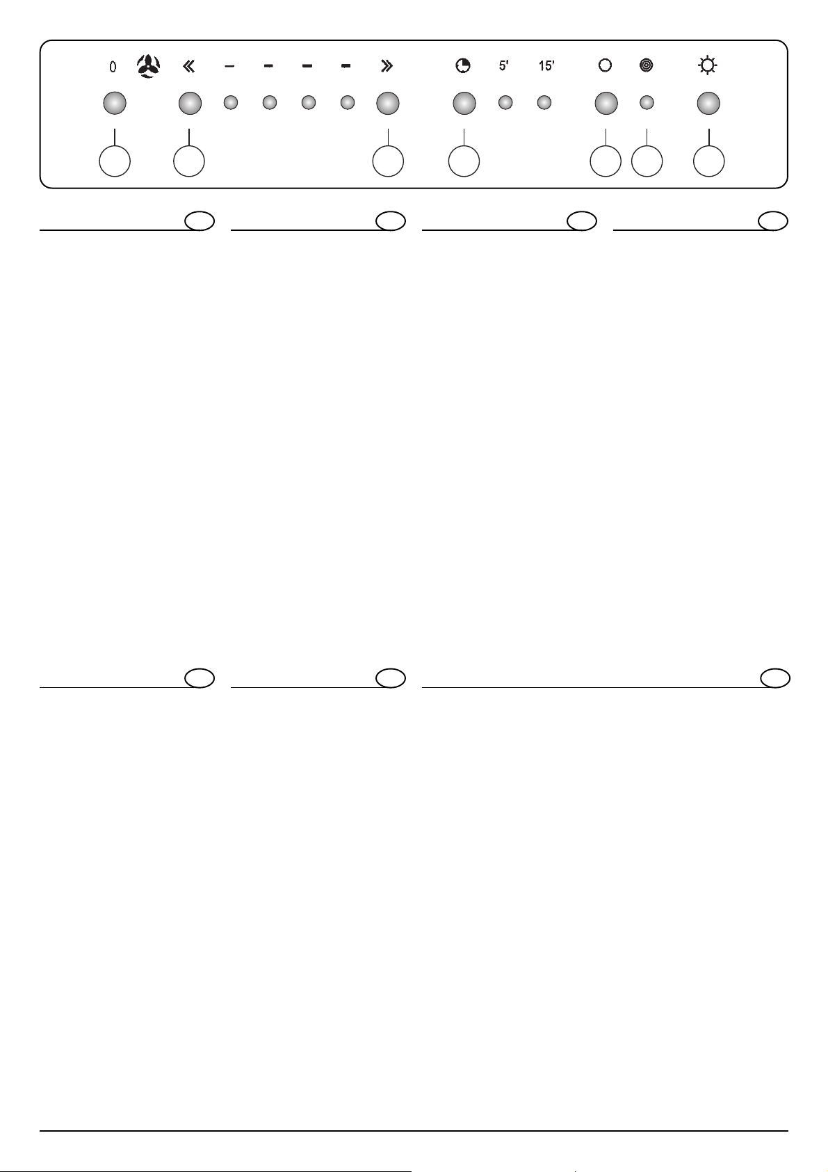
12 3 4 5F6
COMANDI E FUNZIONI
1 = STOP MOTORE
2 = DIMINUISCE LA VELOCIT A’
3 = AUMENT A LA VELOCITA
4 = TIMER 5'/15'
5 = AZZERAMENTO FIL TRI
6 = ON/OFF LUCE
F = SPIA SATURAZIONE FILTRO
- PULSANTE 4: Inserisce e disinserisce il timer.
Spegnimento automatico sulla velocità in
funzione.
Led acceso = timer inserito
T empo durata 5'/15'
- PULSANTE 5: Dopo aver sostituito i filtri carbone, premere per almeno 3 sec. il tasto
fino allo spegnimento della luce.
- PULSANTE 4+5: Programmazione codice
telecomando. Mantenere premuti i due
pulsanti per almeno 3 sec. Un beep segnala il riconoscimento del modo programmazione.
Senza lasciare i pulsanti premere uno dei
tasti del telecomando. Un beep segnala la
ricezione e memorizzazione del codice.
- LED F: Indica la saturazione del filtro carbone.
E’ segnalata anche quando la cappa viene utilizzata in versione aspirante.
- TELECOMANDO:
1°pulsante = ON /l°Vel/2°Vel/3°Vel/ 4°Vel/
OFF
2°pulsante = ON/OFF timer
3°pulsante = ON/OFF luce
I
BEDIENELEMENTE UND FUNKTIONEN
1 = STOPPTASTE MOTOR
2 = GESCHWINDIGKEITSMINDERUNG
3 = GESCHWINDIGKEITSERHÖHUNG
4 = TIMER 5'/15'
5 = FILTER-NULLSTELLUNG
6 = ON/OFF BELEUCHTUNG
F = FILTERSÄTTIGUNGS-ANZEIGELEUCHTE
- TASTE 4: Ein- und Ausschalten des Timers.
Automatisches Ausschalten auf der
laufenden Geschwindigkeit.
Led leuchtet = Timer eingeschaltet
Dauer 5'/15'
- TASTE 5: Nach Austausch des
Aktivkohlefilters muss diese Taste für
mindestens 3 Sek., d.h. bis zum
Ausschalten des Lichtes, gedrückt werden.
- TASTE 4+5: Fernbedienungs-Codeeingabe.
Halten Sie die beiden Tasten für mindestens 3
Sek. gedrückt. Ein kurzes akustisches Signal zeigt
an, dass die Eingabe anerkannt wurde.
Die Tasten noch nicht freilassen und gleichzeitig
eine der Tasten der Fernbedienung drücken.
Ein kurzes akustisches Signal meldet die
korrekte Aufnahme und Speicherung des
eingegebenen Codes.
- LED F: Zeigt die Sättigung des
Aktivkohlefilters an. Diese wird auch dann
angezeigt, wenn die Dunstabzugshaube in
der Abluftversion eingesetzt wird.
- FERNBEDIENUNG:
1.TASTE = ON /l.Geschw./2.Geschw./
3.Geschw./4.Geschw./OFF
2.TASTE = ON/OFF Timer
3.TASTE = ON/OFF Beleuchtung
D
CONTROLS AND FUNCTIONS
1 = MOTOR STOP
2 = DECREASES THE SPEED
3 = INCREASES THE SPEED
4 = 5'/15' TIMER
5 = FILTER RESET
6 = ON/OFF LIGHT
F = SATURATED FILTER LED
- BUTTON 4: Activates and deactivates the timer. Automatically turns off at the selected
speed.
LED on = timer activated
Duration 5'/15'
- BUTTON 5: After having replaced the coal
filters, press this button for at least 3
seconds until the light turns off.
- BUTTON 4+5: Remote control code
programming. Keep both buttons pressed
down for at least 3 seconds. A beep will
indicate the programming mode has been
accepted.
Without letting go of the buttons, press one
of the remote control buttons. A beep will
indicate the code has been accepted and
stored.
- LED F: Indicates that the coal filter is
saturated.
This is also indicated when the hood is used
in vented mode.
- REMOTE CONTROL:
1stbutton = ON /1st Speed/2
Speed/3rd Speed/4th Speed/OFF
2nd button = Timer ON/OFF
3rdbutton = Light ON/OFF
GB
nd
MANDOS Y FUNCIONES
1 = P ARADA DEL MOTOR
2 = DISMINUYE LA VELOCIDAD
3 = AUMENT A LA VELOCIDAD
4 = TIMER 5'/15'
5 = AJUSTE DE FILTROS
6 = ON/OFF LUZ
F = LUZ INDICADORA DE SATURACIÓN
DEL FIL TRO
- BOTÓN 4: Activa y desactiva el timer.
Apagado automático de la velocidad que
está funcionando.
Led encendido = timer activado
Tiempo de duración 5'/15'
- BOTÓN 5 : Después de haber sustituido los
filtros de carbón, pulse la tecla, durante 3 seg.
como mínimo, hasta que se apague la luz.
- BOTÓN 4+5 : Programación código
telemando. Mantenga pulsados los dos
botones durante 3 seg. como mínimo. Una
señal acústica indica el reconocimiento del
modo de programación .
Sin soltar los botones, pulse una de las
teclas del telemando. Una señal acústica
indica la recepción y memorización del
código.
- LED F :Indica la saturación del filtro de
carbón.
Se señala también cuando la campana se
utiliza en versión aspirante.
- TELEMANDO :
1° botón = ON /l°Vel/2°Vel/3°Vel/4°Vel/OFF
2° botón = ON/OFF timer
3° botón = ON/OFF luz
E
COMMANDES ET FONCTIONS
1 = ARRET MOTEUR
2 = DIMINUE LA VITESSE
3 = AUGMENTE LA VITESSE
4 = PROGRAMMATEUR 5'/15'
5 = MISE A ZERO FIL TRES
6 = ON/OFF ECLAIRAGE
F = VOY ANT SATURATION FIL TRE
- BOUTON-POUSSOIR 4: Branche et débranche le programmateur.
Arrêt automatique sur la vitesse en marche.
Led allumé = programmateur branché
Durée 5'/15'
- BOUTON-POUSSOIR 5: Après avoir remplacé les filtres charbon, appuyez pendant
au moins 3 secondes sur la touche jusqu’à
ce que la lumière s’éteigne.
- BOUTON-POUSSOIR 4+5: Programmation code
télécommande. Continuez à appuyer sur les
deux boutons-poussoirs pendant au moins 3
secondes Un bip indique que le mode programmation a été accepté.
Sans lâcher les boutons-poussoirs appuyez sur l’une des touches de la télécommande. Un bip indique la réception et la
mise en mémoire du code.
- LED F :Indique la saturation du filtre charbon.
Cette dernière est signalée même
quand la hotte est utilisée en version
évacuation.
- TELECOMMANDE :
ère
l
touche = ON /l
2e touche = ON/OFF programmateur
3e touche = ON/OFF éclairage
ère
Vit/2eVit/3eVit/4eVit/OFF
F
BEDIENING EN FUNCTIES
1 = STOP MOTOR
2 = VERMINDER SNELHEID
3 = VERMEERDER SNELHEID
4 = TIMER 5’/15’
5 = FIL TERS OP NUL ZETTEN
6 = ON/OFF VERLICHTING
F = LAMPJE VERZADIGING FILTER
- KNOP 4:Zet de timer aan en uit.
Automatische uitschakeling van de
snelheid die in werking is.
LED aan= timer aan.
Tijdsduur 5’/15’
- KNOP 5: na het vervangen van de koolfilter
houdt u de knop minstens 3 sec. ingedrukt
totdat het lampje uit gaat.
- KNOP 4+5:programmering code
afstandsbediening. Houd de twee knoppen
minstens 3 sec. ingedrukt. Een pieptoon
betekent dat de modus van de
programmering herkent is.
Zonder de knoppen los te laten drukt u op
een van de knoppen van het
bedieningspaneel. Een pieptoon betekent
de ontvangst en het memorizeren van de
code.
- LED F: Betekent dat de koolfilter verzadigd
is.
Dit geldt ook voor de afzuigversie van de
kap.
- BEDIENINGSPANEEL:
1° knop= ON/snelheden 1-2-3-4/OFF
2°knop= ON/OFF timer
3°knop= ON/OFF verlichting
NL
ПРИБОРЫ УПРАВЛЕНИЯ И ФУНКЦИИ
1 = ОТКЛЮЧЕНИЕ ДВИГАТЕЛЯ
2=СНИЖЕНИЕ СКОРОСТИ
3=ПОВЫШЕНИЕ СКОРОСТИ
4=ТАЙМЕР 5'/15'
5=УСТАНОВКА НУЛЯ ФИЛЬТРОВ
6=СВЕТ ON/O2FF (ВКЛЮЧЕН ВЫКЛЮЧЕН)
F=СИГНАЛЬНАЯ ЛАМПОЧКА
ЗАСОРЕНИЯ ФИЛЬТРА
- КНОПКА 4 : При нажатии на
данную кнопку включается и
выключается таймер. Вытяжной
колпак выключается автоматически
при заданной скорости.
Сигнальная лампочка горит = таймер
включен
Продолжительность 5'/15'
- КНОПКА 5 : После того, как угольные
фильтры будут заменены, нажмите
на данную кнопку и держите ее
нажатой, по меньшей мере, в
течение 3 сек. до тех пор, пока не
погаснет свет.
- КНОПКА 4+5 : Программирование
кода дистанционного управления.
Держать нажатыми обе кнопки, по
меньшей мере, в течение 3 сек.
Звуковой сигнал сообщит Вам о
распознавании режима
программирования.
Не отпуская кнопки, нажмите на одну
из кнопок дистанционного
управления. Звуковой сигнал
сообщит Вам о приеме и
RU
запоминании кода.
- СИГНАЛЬНАЯ ЛАМПОЧКА (СИД) F :
Загорание данной лампочки говорит
о засорении угольного фильтра.
Сигнал о засорении угольного
фильтра появляется и тогда, когда
вытяжной колпак используется во
всасывающей функции.
- ДИСТАНЦИОННОЕ УПРАВЛЕНИЕ:
1я кнопка = ON /l-я скорость/2-я
скорость/3-я скорость/4-я скорость/
OFF
2 я кнопка = таймер ON/OFF
(ВКЛЮЧЕН - ВЫКЛЮЧЕН)
3 я кнопка = свет ON/OFF (ВКЛЮЧЕН -
ВЫКЛЮЧЕН)
10
J129
Page 10

Fig.1
MODELLO ISOLA 7 E
Fig.2
Fig.3
Fig.5
Fig.4
Fig.7
Fig.6
Fig.8
11J129
Page 11

MODELLO ISOLA 7 E
I
MONTAGGIO DELLA CAPPA VERSIONE ASPIRANTE
Per poter utilizzare questa funzione munirsi di un tubo estensibile non
combustibile Ø150 mm da collegare al soffitto ,che andrà successivamente collegato al raccordo “A” fig2
Per il montaggio della cappa procedere come di seguito:
1) posizionare la dima di foratura sul soffitto eseguire i 4 fori Ø 10 mm
ed inserire i tasselli fig1
2) fissare il tubo Ø 150 mm al soffitto e stenderlo per una lunghezza
maggiore della struttura telescopica.
3) posizionare la struttura telescopica, precedentemente regolata,e fissarla al soffitto con le 4viti fig1
4) infilare il tubo con la sgrigliatura rivolta al soffitto e fissarlo lateralmente alla struttura telescopica con le due viti fig1
5) inserire l’altro tubo e mantenerlo sollevato con del nastro adesivo
6) sollevare la cappa,e dopo aver bloccato il tubo Ø150 mm al raccordo “A” tramite una fascetta,fissarla alla struttura telescopica con le
4 viti e rondelle fig2
7) allentare le due viti di fissaggio scocca fig4.A
8) abbassare il tubo e infilarlo nella scocca fig3.A
9) munirsi di un giravite e alzare le due linguette all’interno della scocca (anteriore e posteriore),per fare aderire il camino al mantello fig3.B
10) posizionare la scatola comandi e stringere le due viti di fissaggio
senza serrare a fondo fig4.C
11) infilare il profilo sagomato sul bordo della scocca fig4.B
12) bloccare il cristallo con 4 viti M6x20 e boccole, senza serrare a fondo fig7
13) serrare le due viti di fissaggio scocca precedentemente allentate al
punto (7) fig4.A
MONTAGGIO DELLA CAPPA VERSIONE FILTRANTE
Dopo esservi procurati il corredo filtrante procedere nel seguente modo
fig5
1) fissare il raccordo “B” al raccordo filtrante “R” con le due viti
2) fissare alla struttura telescopica”M” il raccordo filtrante “R”con le 4
viti
3) collegare un tubo estensibile non combustibile Ø 150mm al raccordo “B”, tramite una fascetta fig5,che andrà successivamente collegato al raccordo “A” fig2
4) stendere il tubo flessibile per una lunghezza maggiore della struttura telescopica
5) posizionare la dima di foratura sul soffitto eseguire i 4 fori Ø 10mm
ed inserire i tasselli fig1
6) procedere al montaggio della struttura telescopica e della cappa
come specificato nel paragrafo precedente a partire dal punto 3.
MONTAGGIO FILTRO CARBONE fig6
1) Rimuovere la griglia alluminio“G”
2) Posizionare il filtro carbone “C” nella sua sede
3) Bloccare il filtro con gli appositi pomelli “P”
SOSTITUZIONE LAMPADE fig8
1) Disinserire l’apparecchio dalla rete elettrica.
2) Rimuovere la ghiera cromata girandola.
3) Sostituire la lampada danneggiata utilizzando esclusivamente lampade alogene da 20W-max.
4) Rimontare la ghiera .
MODELL ISOLA 7 E
MONTAGE DER ABLUFT-DUNSTABZUGSHAUBE
Zum Einsatz der Dunstabzugshaube in dieser Version beschaffen Sie
sich ein ausziehbares, nicht brennbares Rohr Ø150 mm, das an der Decke
befestigt werden muss und das anschließend an den Anschluss “A”
(Abb.2) anzuschließen ist.
Zur Montage der Dunstabzugshaube verfahren Sie dann wie folgt:
1) Legen Sie die Bohrschablone an die Decke an, bohren Sie die 4 Löcher (Ø 10 mm) und setzen Sie die Dübel ein (Abb.1).
2) Befestigen Sie das Rohr (Ø 150 mm) an der Decke und ziehen Sie es
so weit aus, dass es die Länge des Teleskopschachtes überragt.
3) Setzen Sie den vorher auf die korrekte Länge gebrachten Teleskopschacht an und befestigen Sie diesen mittels der 4 Schrauben an
der Decke (Abb.1).
4) Setzen Sie das Rohr so ein, dass das Gitterteil zur Decke gerichtet ist,
und befestigen Sie es mittels der beiden Schrauben seitlich am
T eleskopschacht. (Abb.1)
5) Setzen Sie das andere Rohr ein und halten Sie dieses mit Klebeband
hoch.
6) Heben Sie die Dunstabzugshaube an und befestigen Sie diese, nicht
ohne vorher das Ø150 mm Rohr mittels einer Schelle am Anschluss
„A“ befestigt zu haben, am Teleskopschacht. Verwenden Sie hierzu
die 4 Schrauben und Unterlegscheiben. (Abb.2)
7) Lösen Sie die beiden Gehäusebefestigungsschrauben (Abb.4.A)
8) Ziehen Sie das Rohr aus und führen Sie es in das Gehäuse ein
(Abb.3.A).
9) Nehmen Sie einen Schraubenzieher zur Hand und heben Sie damit
die beiden im Gehäuseinnern (vorne und hinten) befindlichen Laschen an, damit der Schacht fest am Gehäusemantel anhaften kann.
(Abb.3.B)
10) Setzen Sie das Armaturengehäuse an und ziehen Sie die beiden
Befestigungsschrauben nicht ganz bis zum Anschlag an. (Abb.4.C)
11) Setzen Sie den Profilrahmen auf den Gehäuserand. (Abb.4.B)
12) Befestigen Sie das Kristallglas mittels 4 Schrauben M6x20 und Buch-
D
sen, ziehen Sie diese jedoch nicht ganz an.
13) Ziehen Sie die eingangs gelockerten zwei Gehäusebefestigungsschrauben (siehe Abs. 7) nun fest an. (Abb.4.A)
MONTAGE DER UMLUFT-DUNSTABZUGSHAUBE
Nachdem Sie sich den gesamten Filter-Montagesatz besorgt haben,
verfahren Sie gemäß Abb.5 wie folgt:
1) Befestigen Sie den Anschluss „B“ mittels der beiden Schrauben am
Filteranschluss „R“.
2) Befestigen Sie den Filteranschluss „R“ am Teleskopschacht „M“ mittels 4 Schrauben.
3) Schließen Sie ein ausziehbares, nicht brennbares Rohr (Ø 150mm)
zuerst mittels einer Schelle (Abb.5) an den Anschluss “B” an; schließen Sie es dann an den Anschluss “A” (Abb.2) an.
4) Ziehen Sie das Flexrohr so weit aus, dass es die Länge des T eleskopschachtes überragt.
5) Legen Sie die Bohrschablone an die Decke an, bohren Sie die 4 Löcher (Ø 10mm) und setzen Sie die Dübel ein. (Abb.1)
6) Verfahren Sie zur Montage des Teleskopschachtes und der Dunstabzugshaube so wie im vorigen Abschnitt (ab Punkt 3) beschrieben.
MONTAGE DES AKTIVKOHLEFILTERS (Abb.6)
1) Nehmen Sie das Alugitter „G“ ab.
2) Legen Sie den Aktivkohlefilter „C“ in seinen Sitz ein.
3) Blockieren Sie den Filter mittels der entsprechenden Knäufe „P“.
LAMPENWECHSEL (Abb.8)
1) Schalten Sie die Dunstabzugshaube vom Stromnetz ab.
2) Schrauben Sie die verchromte Nutmutter ab.
3) Tauschen Sie die beschädigte Lampe aus; verwenden Sie hierzu
ausschließlich max. 20W-Halogenlampen.
4) Schrauben Sie die Nutmutter wieder auf.
12
J129
Page 12

ISOLA 7 E MODEL
GB
HOOD ASSEMBLY - VENTED INSTALLATION
To use the vented operating mode, fasten one end of a Ø 150 mm noncombustible extending pipe to the ceiling and the other to the connector
“A” (fig. 2).
Assemble the hood as follows:
1) position the drilling template on the ceiling and drill the four Ø 10
mm holes indicated, then place the rawlplugs in the relative holes
(fig. 1);
2) fasten the Ø 150 mm pipe to the ceiling and extend it to a length
greater than the telescopic flue;
3) position the telescopic flue, which you previously adjusted, and secure
it to the ceiling with the 4 screws (fig. 1);
4) insert the unit with the grid near the ceiling and fasten it on the sides
to the telescopic flue using the two screws (fig. 1);
5) insert the other unit and keep it raised using adhesive tape;
6) lift the hood and, once you have secured the Ø 150 mm pipe to
connector “A” with a clamp, fasten it to the telescopic flue using the 4
screws and washers (fig. 2);
7) loosen the two base section fastening screws (fig. 4A);
8) lower the unit into the base section (fig. 3A);
9) using a screwdriver, raise the two tabs inside the base section (front
and rear) to ensure the flue adheres to the base section (fig. 3B);
10) position the controls box and tighten the two fastening screws without
screwing them in fully (fig. 4C);
11) thread the shaped border along the perimeter of the base section
(fig. 4B);
12) secure the glass canopy in place using four M6x20 screws and
bushes, without screwing them in fully (fig. 7);
13) fasten the two base section fastening screws you previously loosened
in point 7 above (fig. 4A);
HOOD ASSEMBLY - VENTLESS INSTALLATION
Once you have the relevant assembly kit, proceed as follows (fig. 5):
1) fasten connector “B” to the filtering connector “R” using the two screws;
2) fasten the filtering connector “R” to the telescopic flue “M” using the 4
screws;
3) fasten one end of a Ø 150 mm non-combustible extending pipe to
connector “B” using a clamp (fig. 5), and the other to connector “A”
(fig. 2);
4) extend the flexible pipe to a length greater than the telescopic flue;
5) position the drilling template on the ceiling and drill the four Ø 10mm
holes indicated, then place the rawlplugs in the relative holes (fig. 1);
6) proceed with the telescopic flue and hood assembly as specified in
the previous paragraph from point 3 onwards.
CARBON FILTER ASSEMBLY fig. 6
1) Remove the aluminium grid “G”;
2) Position the carbon filter “C” in its seat;
3) Secure the filter in place using knobs “P”.
LAMP REPLACEMENT fig. 8
1) Unplug the appliance from the electrical power supply;
2) Screw off the chrome-plated ring nut;
3) Replace the faulty lamp, using only 20W (max) halogen lamps;
4) Reposition the ring nut.
MODELO ISLA 7 E
MONTAJE DE LA CAMPANA EN LA VERSIÓN ASPIRANTE
Para poder utilizar esta función se debe disponer de un tubo extensible,
no combustible, de Ø150 mm. que se debe conectar al techo y que
posteriormente se conectará a la unión “A” fig. 2
Para el montaje de la campana proceda de la siguiente manera:
1) coloque la plantilla de perforación en el techo y realice los 4 orificios
de Ø 10 mm. e introduzca los tacos fig. 1
2) fije el tubo de Ø 150 mm al techo y extiéndalo hasta una longitud
mayor que la estructura telescópica.
3) coloque la estructura telescópica, precedentemente regulada, y fíjela
al techo con los 4 tornillos fig.1
4) introduzca el tubo con el enrejado dirigido hacia el techo y fíjelo
lateralmente a la estructura telescópica con los dos tornillos fig.1
5) introduzca el otro tubo y manténgalo elevado con cinta adhesiva.
6) eleve la campana y después de haber bloqueado el tubo de Ø150
mm. a la unión “A” mediante una abrazadera, fíjela a la estructura
telescópica con los 4 tornillos y arandelas fig.2
7) afloje los dos tornillos de fijación del armazón.
8) baje el tubo e introdúzcalo en el armazón fig.3.A
9) utilizando un destornillador, levante las dos lengüetas que se
encuentran en el interior del armazón (anterior y posterior) para hacer
adherir la chimenea a la envuelta fig.3.B
10) coloque la caja de mandos y apriete los dos tornillos de fijación sin
atornillarlos a fondo fig.4.C
11) introduzca el perfil moldurado en el borde del armazón fig.4.B
12) bloquee el cristal con los 4 tornillos M6x20 y los manguitos sin apretar
a fondo fig.7
13) apriete los dos tornillos de fijación del armazón precedentemente
aflojados en el punto (7) fig.4.A
E
1) fije la unión “B” a la unión filtrante “R” con los dos tornillos
2) fije a la estructura telescópica “M” la unión filtrante “R” con los 4
tornillos
3) conecte un tubo extensible no combustible, de Ø 150mm a la unión
“B” mediante una abrazadera fig.5 que posteriormente se conectará
a la unión “A” fig.2
4) extienda el tubo flexible hasta una longitud mayor que la estructura
telescópica.
5) coloque la plantilla de perforación en el techo y realice los 4 orificios
de Ø 10mm. e introduzca los tacos fig. 1
6) proceda al montaje de la estructura telescópica y de la campana
como se indica en el párrafo precedente a partir del punto 3.
MONTAJE DEL FILTRO DE CARBÓN fig.6
1) Quite la rejilla de aluminio “G”
2) Coloque el filtro de carbón “C” en su lugar
3) Bloquee el filtro con las correspondientes perillas “P”
SUSTITUCIÓN DE LAS LÁMPARAS fig.8
1) Desconecte el aparato de la red eléctrica.
2) Quite la virola cromada girándola.
3) Sustituya la lámpara dañada utilizando exclusivamente lámparas
halógenas de 20 W como máximo.
4) Vuelva a colocar la virola.
MONTAJE DE LA CAMPANA EN LA VERSIÓN FILTRANTE
Después de haber conseguido el equipo filtrante, proceda del siguiente
modo fig.5
13J129
Page 13

MODELE ISOLA 7 E
F
MONTAGE DE LA HOTTE VERSION ASPIRANTE
Pour utiliser la hotte dans cette version, utilisez un tuyau extensible
ignifuge Ø150 mm à raccorder au plafond et à relier ensuite au raccord “A” fig2
Pour monter la hotte, procédez comme suit :
1) positionnez le gabarit, percez 4 trous Ø 10 mm et enfilez les chevilles voir fig1
2) fixez le tuyau Ø 150 mm au plafond et étirez-le sur une longueur
supérieure à la structure télescopique.
3) positionnez la structure télescopique, précédemment réglée et
fixez-la au plafond à l’aide des 4 vis fig1
4) enfilez le tuyau, grille tournée vers le haut et fixez-le sur les côtés à la structure télescopique à l’aide des deux vis fig1
5) enfilez l’autre tuyau et gardez-le soulevé à l’aide de ruban adhésif
6) soulevez la hotte et après avoir bloqué le tuyau Ø150 mm au
raccord “A” à l’aide d’un collier, fixez-la à la structure télescopique à l’aide des 4 vis et des rondelles fig2
7) desserrez les deux vis de fixation du corps de hotte fig4.A
8) baissez le tuyau et enfilez-le dans le corps de hotte fig3.A
9) à l’aide d’un tournevis soulevez les deux languettes situées à
l’intérieur du corps de hotte (avant et arrière) pour bien faire
adhérer la cheminée au manteau fig3.B
10) positionnez le boîtier de commandes et vissez les deux vis de
fixation sans serrer à fond fig4.C
11) montez le profil façonné sur le bord du corps de hotte fig4.B
12) fixez la jupe en verre à l’aide de 4 vis M6x20 et de douilles, sans
serrer à fond fig7
13) serrez les deux vis de fixation du corps de hotte précédemment
desserrées au point (7) fig4.A
MONTAGE DE LA HOTTE VERSION FILTRANTE
Après vous être procuré le kit de transformation en version recyclage,
procédez comme suit fig5
1) fixez le raccord “B” au raccord filtrant “R” à l’aide des deux vis
2) fixez à la structure télescopique ”M” le raccord filtrant “R” à l’aide des
4 vis
3) raccordez le tuyau extensible ignifuge Ø 150 mm au raccord “B”, à
l’aide d’un collier fig5, qui sera ensuite relié au raccord “A” fig2
4) étirez le tuyau flexible sur une longueur supérieure à celle de la structure télescopique
5) positionnez le gabarit, percez 4 trous Ø 10 mm et enfilez les chevilles
voir fig1
6) procédez au montage de la structure télescopique et de la hotte
comme indiqué au paragraphe précédent à partir du point 3.
MONTAGE FILTRE A CHARBON fig6
1) Enlevez la grille aluminium ”G”
2) Placez le filtre à charbon “C” à l’emplacement prévu
3) Fixez le filtre à l’aide des boutons prévus “P”
REMPLACEMENT DES LAMPES fig8
1) Coupez l’alimentation électrique de l’appareil.
2) T ournez l’anneau chromé pour l’enlever.
3) Remplacez la lampe grillée en utilisant exclusivement des lampes
halogènes 20W-max.
4) Remontez l’anneau.
MODEL ISOLA 7 E
MONTEREN VAN DE KAP AFZUIGENDE VERSIE
Bij deze functie heeft u een uitrekbare, onbrandbare buis Ø150 mm nodig
die aan het plafond wordt bevestigd en aan het aansluitdstuk “A” afb2
Voor het monteren van de kap gaat u als volgt te werk:
1) plaats het gatenpatroon op het plafond, boor de 4 gaten Ø 10 mm
en breng de pluggen aan afb1
2) bevestig de buis Ø 150 mm aan het plafond en rek hem uit tot een
lengte die langer is dan die van de telescopische structuur.
3) plaats de tevoren geregelde telescopische structuur en bevestig hem
aan het plafond met de 4 schroeven afb1
4) plaats de buis met de roosterkant naar het plafond gericht en bevestig
hem aan de zijkant aan de telescopische structuur met de twee
schroeven afb1
5) steek de andere buis erin en houd hem omhoog met plakband
6) hef de kap op en bevestig hem, nadat u de buis Ø150 mm aan
het aansluitstuk “A” heeft bevestigd met een schroefklem, aan
de telescopische structuur met de 4 schroeven en sluitringen
afb2
7) schroef de twee bevestigingsschroeven van de romp los afb4.A
8) trek de buis naar beneden en steek hem in de romp afb3.A
9) muneem een schroevendraaier en zet de twee lippen in de romp
(voor en achter) omhoog om het rookkanaal te laten aansluiten aan
de mantel afb3.B
10) plaats de bedieningsdoos en schroef de twee bevestigingsschroeven
zonder te veel kracht vast afb4.C
11) plaats het profielstuk op de rand van de romp afb4.B
12) blokkeer het glas met 4 schroeven M6x20 en naafringen, zonder
geheel door te schroeven afb7
13) schroef de twee bevestigingsschroeven van de romp vast die
voorheen los waren gedraaid tot punt (7) fig4.A
NL
MONTEREN VAN DE KAP FILTRERENDE VERSIE
Nadat u zich heeft voorzien van de filtreer-kit gaat u als volgt te werk
afb5
1) bevestig de aansluiting “B” aan de filtreer-aansluiting “R” met de twee
schroeven
2) bevestig de filtreer-aansluiting “R” met de 4 schroeven aan de
telescopische structuur ”M”
3) coverbind een uitrekbare, onbrandbare buis Ø 150mm aan de
aansluiting “B”, met een schroefklem fig5, die vervolgens wordt
verbonden aan de aansluiting “A” afb2
4) rek de flexibele buis uit tot een lengte die langer is dan de
telescopische structuur
5) plaats het gatenpatroon tegen het plafond, boor de 4 gaten Ø 10mm
en breng de pluggen aan fig1
6) monteer de telescopische structuur en de kap zoals aangegeven in
de vorige paragraaf, beginnend vanaf punt 3.
MONTEREN VAN KOOLFILTER afb6
1) Verwijder de aluminium rooster “G”
2) Plaats de koolfilter “C” in zijn behuizing
3) Blokkeer de filter met de betreffende knoppen “P”
VERVANGEN LAMP afb8
1) Sluit de stroom af.
2) Verwijder de chroom knopsteunring.
3) Vervang de uitgebrande lamp uitsluitend met een halogeenlamp
van max 20W.
4) Monteer de steunring weer.
14
J129
Page 14

МОДЕЛЬ ISOLA 7 E
RU
МОНТАЖ КУХОННОЙ ВЫТЯЖКИ С ВЫВОДОМ ВОЗДУХА В
АТМОСФЕРУ
Для использования данной функции подсоединить раздвижную
трубу из невозгораемого материала Ш150 мм к потолку и затем
соединить ее с патрубком «А» рис. 2.
Для монтажа вытяжки выполнить операции в следующем порядке:
1) приложить шаблон для просверливания отверстий к потолку,
просверлить 4 отверстия Ш 10 мм и вставить в них пробки под
винты рис. 1.
2) прикрепить трубу Ш 150 мм к потолку и вытянуть ее на длину,
превышающую длину раздвижной опоры.
3) установить заранее отрегулированную раздвижную структуру
и прикрепить ее к потолку 4 винтами рис. 1.
4) продеть трубу с решетками, направленными в потолок, и прикрепить
ее с боков к раздвижной структуре двумя винтами рис. 1.
5) вставить другую трубу и зафиксировать ее вверху при помощи
клейкой ленты.
6) поднять вытяжку и, прикрепив трубу Ш 150 мм к патрубку «А»
при помощи хомута, прикрепить ее к раздвижной структуре при
помощи 4 винтов и шайб рис. 2.
7) отвинтить два крепежных винта кожуха рис. 4.А.
8) опустить трубу и продеть ее в кожух рис. 3.А.
9) при помощи отвертки поднять два язычка внутри кожуха
(передний и задний), чтобы воздухоотводная трубка плотно
прилегла к кожуху рис. 3.В.
10) установить коробку управления и завинтить два крепежных
винта, но не до упора рис. 4.С.
11) надеть изогнутый профиль на край кожуха рис. 4.В.
12) зафиксировать стекло при помощи 4 винтов М6х20 и втулок,
но не завинчивая до упора рис. 7.
13) завинтить до упора два крепежных винта кожуха, которые были
ранее отвинчены в пункте (7) рис. 4.А.
МОНТАЖ МОДЕЛИ ФИЛЬТРУЮЩЕЙ ВЫТЯЖКИ
Имея в распоряжении фильтрующий комплект, выполнить
операции в следующем порядке рис.5.
1) соединить патрубок «В» с фильтрующим патрубком “R” при
помощи двух винтов.
2) прикрепить к раздвижной структуре «М» фильтрующий
патрубок “R” при помощи 4 винтов.
3) прикрепить раздвижную трубу Ш 150 мм из невозгораемого
материала к патрубку «В» при помощи хомута рис. 5, который
затем соединяется с патрубком «А» рис. 2.
4) вытянуть гибкую трубу на длину, превышающую длину
раздвижной структуры.
5) приложить шаблон для просверливания отверстий к потолку,
просверлить 4 отверстия Ш 10 мм и вставить в них пробки под
винты рис. 1.
6) установить раздвижную структуру и вытяжку, как описано в
предыдущем параграфе, и выполнить операции, начиная с
пункта 3.
МОНТАЖ ФИЛЬТРА С АКТИВИРОВАННЫМ УГЛЕМ рис. 6
1) Снять алюминиевую решетку ”G”.
2) Установить угольный фильтр «С» в свое гнездо.
3) Зафиксировать фильтр при помощи специальных маховичков
«Р».
ЗАМЕНА ЛАМП рис. 8
1) Отключить вытяжку от сети электропитания.
2) Повернуть и снять хромированную блокировочную гайку.
3) Заменить поврежденную лампу исключительно на галогеновую
лампу макс. мощностью 20 Вт.
4) Восстановить на место блокировочную гайку.
15J129
Page 15

Fig.1 Fig.2
Fig.3
MODELLO ISOLA TIBERINA ,ISOLA BALI
Fig.5
ISOLA TIBERINA
ISOLA BALI
Fig.6
Fig.4
MODELLO ISOLA TIBERINA ,ISOLA BALI
MONTAGGIO DELLA CAPPA VERSIONE ASPIRANTE
Per poter utilizzare questa funzione munirsi di un tubo estensibile non
combustibile Ø 150 mm
da collegare al soffitto ,che andrà successivamente collegato al raccordo “A” fig2
Per il montaggio della cappa procedere come di seguito:
1) posizionare la dima di foratura sul soffitto eseguire i 4 fori Ø 10 mm
ed inserire i tasselli fig1
2) fissare il tubo Ø 150 mm al soffitto e stenderlo per una lunghezza
maggiore della struttura telescopica.
3) posizionare la struttura telescopica, precedentemente regolata,e fissarla al soffitto con le 4viti fig1
4) infilare il tubo con la sgrigliatura rivolta al soffitto e fissarlo lateralmente alla struttura telescopica con le due viti fig1
5 )inserire l’altro tubo e mantenerlo sollevato con del nastro adesivo
6) sollevare la cappa,e dopo aver bloccato il tubo Ø150 mm al raccordo “A” tramite una fascetta,fissarla alla struttura telescopica con le
4 viti e rondelle fig2
7) abbassare il tubo e fissarlo lateralmente alla cappa con le due viti,
nel modello Isola Bali il tubo non và fissato con le viti fig5
MONTAGGIO DELLA CAPPA VERSIONE FILTRANTE
Dopo esservi procurati il corredo filtrante procedere nel seguente modo
fig3
1) fissare il raccordo “B” al raccordo filtrante “R” con le due viti
2) fissare alla struttura telescopica”M” il raccordo filtrante “R”con le 4
viti
3) collegare un tubo estensibile non combustibile Ø 150mm al raccordo “B”, tramite una fascetta ,che andrà successivamente collegato
al raccordo “A” fig2
I
4) stendere il tubo flessibile per una lunghezza maggiore della struttura telescopica
5) posizionare la dima di foratura sul soffitto eseguire i 4 fori Ø 10mm
ed inserire i tasselli fig1
6) procedere al montaggio della struttura telescopica e della cappa
come specificato nel paragrafo precedente a partire dal punto (3)
MONTAGGIO FILTRO CARBONE fig6
1) Rimuovere la griglia alluminio “G”
2) Posizionare il filtro carbone “C” nella sua sede
3) Bloccare il filtro con gli appositi pomelli “P”
SOSTITUZIONE LAMPADE fig4
1) Disinserire l’apparecchio dalla rete elettrica
2) Con l’ausilio di un giravite estrarre il telaio porta-vetro del faretto
3) Sostituire la lampada danneggiata utilizzando esclusivamente lampade alogene da 20W-max
4) Rimontare il telaio porta-vetro
16
J129
Page 16

MODELL ISOLA TIBERINA, ISOLA BALI
D
MONTAGE DER ABLUFT-DUNSTABZUGSHAUBE
Zum Einsatz des Lüfters in dieser Version beschaffen Sie sich ein ausziehbares, nicht brennbares Rohr Ø150 mm, das an der Decke zu befestigen ist und das anschließend an den Anschluss “A” Abb.2 anzuschlie-
ßen ist.
Zur Montage der Dunstabzugshaube verfahren Sie dann wie folgt:
1) Legen Sie die Bohrschablone an die Decke an, bohren Sie die 4 Löcher (Ø 10 mm) und setzen Sie die Dübel ein. (Abb.1)
2) Befestigen Sie das Rohr (Ø 150 mm) an der Decke und ziehen Sie es
so weit aus, dass es die Länge des Teleskopschachtes überragt.
3) Setzen Sie den vorher auf die korrekte Länge gebrachten Teleskopschacht an und befestigen Sie diesen mittels der 4 Schrauben an
der Decke (Abb.1).
4) Setzen Sie das Rohr so ein, dass das Gitterteil zur Decke gerichtet ist,
und befestigen Sie es mittels der beiden Schrauben seitlich am
T eleskopschacht. (Abb.1)
5) Setzen Sie das andere Rohr ein und halten Sie dieses mit Klebeband
hoch.
6) Heben Sie die Dunstabzugshaube an und befestigen Sie diese, nicht
ohne vorher das Ø150 mm Rohr mittels einer Schelle am Anschluss
„A“ befestigt zu haben, am Teleskopschacht. Verwenden Sie hierzu
die 4 Schrauben und Unterlegscheiben. (Abb.2)
7) Ziehen Sie das Rohr aus und befestigen Sie es mittels der beiden
Schrauben seitlich an der Dunstabzugshaube; bei Modell Isola Bali
wird das Rohr nicht mit Schrauben befestigt. (Abb.5)
MONTAGE DER UMLUFT-DUNSTABZUGSHAUBE
Nachdem Sie sich den gesamten Filter-Montagesatz besorgt haben,
verfahren Sie gemäß Abb.3 wie folgt:
1) Befestigen Sie mittels der beiden Schrauben den Anschluss „B“ an
den Filteranschluss „R“.
2) Befestigen Sie den Filteranschluss „R“ am Teleskopschacht „M“ mittels 4 Schrauben.
3) Schließen Sie mittels einer Schelle ein ausziehbares, nicht brennbares Rohr (Ø 150mm) an den Anschluss “B” an, schließen Sie es anschließend an den Anschluss “A” (Abb.2) an.
4) ziehen Sie das Flexrohr so weit aus, dass es die Länge des T eleskopschachtes überragt.
5) Legen Sie die Bohrschablone an die Decke an, bohren Sie die 4 Löcher (Ø 10mm) und setzen Sie die Dübel ein. (Abb.1)
6) Verfahren Sie zur Montage des Teleskopschachtes und der Dunstabzugshaube so wie im vorigen Abschnitt (ab Punkt 3) beschrieben.
MONTAGE DES AKTIVKOHLEFILTERS (Abb.6)
1) Nehmen Sie das Alugitter „G“ ab.
2) Legen Sie den Aktivkohlefilter „C“ in seinen Sitz.
3) Blockieren Sie den Filter mittels der entsprechenden Knäufe „P“.
LAMPENWECHSEL (Abb.4)
1) Schalten Sie die Dunstabzugshaube vom Stromnetz ab.
2) Ziehen Sie (unter Zuhilfenahme eines Schraubenziehers) den Glashalterungsrahmen der Leuchte ab.
3) Tauschen Sie die beschädigte Lampe aus; verwenden Sie hierzu
ausschließlich max. 20W-Halogenlampen.
4) Rahmen wieder anmontieren.
ISOLA TIBERINA, ISOLA BALI MODELS
HOOD ASSEMBLY - VENTED INSTALLATION
To use the vented operating mode, fasten one end of a Ø 150 mm noncombustible extending pipe to the ceiling and the other to the connector
“A” (fig. 2).
Assemble the hood as follows:
1) position the drilling template on the ceiling and drill the four Ø 10
mm holes indicated, then place the rawlplugs in the relative holes
(fig. 1);
2) fasten the Ø 150 mm pipe to the ceiling and extend it to a length
greater than the telescopic flue;
3) position the telescopic flue, which you previously adjusted, and secure
it to the ceiling with the 4 screws (fig. 1);
4) insert the unit with the grid near the ceiling and fasten it on the sides
to the telescopic flue using the two screws (fig. 1);
5) insert the other unit and keep it raised using adhesive tape;
6) lift the hood and, once you have secured the Ø 150 mm pipe to
connector “A” with a clamp, fasten it to the telescopic flue using the 4
screws and washers (fig. 2);
7) lower the unit and fasten its sides to the hood using the two screws;
in the Isola Bali model, the unit should not be fastened with the screws
(fig. 5).
HOOD ASSEMBLY - VENTLESS INSTALLATION
Once you have the relevant assembly kit, proceed as follows (fig. 3):
1) fasten connector “B” to the filtering connector “R” using the two screws;
2) fasten the filtering connector “R” to the telescopic flue “M” using the 4
screws;
3) fasten one end of a Ø 150mm non-combustible extending pipe to
connector “B” using a clamp, and the other to connector “A” (fig. 2);
4) extend the flexible pipe to a length greater than the telescopic flue;
GB
5) position the drilling template on the ceiling and drill the four Ø 10mm
holes indicated, then place the rawlplugs in the relative holes (fig. 1);
6) proceed with the telescopic flue and hood assembly as specified in
the previous paragraph from point 3 onwards.
CARBON FILTER ASSEMBLY fig. 6
1) Remove the aluminium grid “G”;
2) Position the carbon filter “C” in its seat;
3) Secure the filter in place using knobs “P”.
LAMP REPLACEMENT fig. 4
1) Unplug the appliance from the electrical power supply;
2) Using a screwdriver, pull out the spotlight glass frame;
3) Replace the faulty lamp, using only 20W (max) halogen lamps;
4) Reposition the spotlight glass frame.
17J129
Page 17

MODELO ISLA TIBERINA ,ISLA BALI
E
MONTAJE DE LA CAMPANA EN LA VERSIÓN ASPIRANTE
Para poder utilizar esta función se debe disponer de un tubo extensible,
no combustible, de Ø150 mm. que se debe conectar al techo y que
posteriormente se conectará a la unión “A” fig. 2
Para el montaje de la campana proceda de la siguiente manera:
1) coloque la plantilla de perforación en el techo y realice los 4 orificios
de Ø 10 mm. e introduzca los tacos fig. 1
2) fije el tubo de Ø 150 mm al techo y extiéndalo una longitud mayor
que la estructura telescópica.
3) coloque la estructura telescópica, precedentemente regulada, y fíjela
al techo con los 4 tornillos fig.1
4) introduzca el tubo con el enrejado dirigido hacia el techo y
fíjelo lateralmente a la estructura telescópica con los dos
tornillos fig.1
5) introduzca el otro tubo y manténgalo elevado con cinta adhesiva.
6) eleve la campana y después de haber bloqueado el tubo de Ø150
mm. a la unión “A” utilizando una abrazadera, fíjela a la estructura
telescópica con los 4 tornillos y arandelas fig.2
7) baje el tubo y fíjelo lateralmente a la campana con los dos tornillos,
en el modelo Isla Bali el tubo no se fija con los tornillos fig.5
MONTAJE DE LA CAMPANA EN LA VERSIÓN FILTRANTE
Después de haber conseguido el equipo filtrante proceda del siguiente
modo fig.3
1) fije la unión “B” a la unión filtrante “R” con los dos tornillos
2) fije a la estructura telescópica “M”, la unión filtrante “R” con los 4
tornillos
3) conecte un tubo extensible no combustible, de Ø 150mm a la unión
“B” utilizando una abrazadera que posteriormente se conectará a
la unión “A” fig.2
4) extienda el tubo flexible hasta una longitud mayor que la estructura
telescópica.
5) coloque la plantilla de perforación en el techo y realice los 4 orificios
de Ø 10mm. e introduzca los tacos fig. 1
6) proceda al montaje de la estructura telescópica y de la campana
como se indica en el párrafo precedente a partir del punto (3).
MONTAJE DEL FILTRO DE CARBÓN fig.6
1) Quite la rejilla de aluminio “G”
2) Coloque el filtro de carbón “C” en su lugar
3) Bloquee el filtro con las correspondientes perillas “P”
SUSTITUCIÓN DE LAS LÁMPARAS fig.4
1) Desconecte el aparato de la red eléctrica.
2) Con la ayuda de un destornillador extraiga el bastidor que contiene
el vidrio del foco
3) Sustituya la lámpara dañada utilizando exclusivamente lámparas
halógenas de 20 W como máximo.
4) Vuelva a colocar el bastidor portavidrio
MODELE ISOLA TIBERINA ,ISOLA BALI
MONTAGE DE LA HOTTE VERSION ASPIRANTE
Pour utiliser la hotte dans cette version, utilisez un tuyau extensible ignifuge Ø
150 mm à raccorder au plafond et à relier ensuite au raccord “A” fig2
Pour monter la hotte, procédez comme suit :
1) positionnez le gabarit, percez 4 trous Ø 10 mm et enfilez les chevilles
voir fig1
2) fixez le tuyau Ø 150 mm au plafond et étirez-le sur une longueur
supérieure à la structure télescopique.
3) positionnez la structure télescopique, précédemment réglée et fixezla au plafond à l’aide des 4 vis fig1
4) enfilez le tuyau, grille tournée vers le haut et fixez-le sur les côtés à la
structure télescopique à l’aide des deux vis fig1
5) enfilez l’autre tuyau et gardez-le soulevé à l’aide de ruban adhésif
6) soulevez la hotte et après avoir bloqué le tuyau Ø150 mm au raccord “A” à l’aide d’un collier, fixez-la à la structure télescopique à
l’aide des 4 vis et des rondelles fig2
7) baissez le tuyau et fixez-le sur les côtés à la hotte à l’aide des deux
vis, sur le modèle Isola Bali le tuyau ne doit pas être fixé à l’aide des
vis fig5
MONTAGE DE LA HOTTE VERSION FILTRANTE
Après vous être procuré le kit de transformation en version recyclage,
procédez comme suit fig3
1) fixez le raccord “B” au raccord filtrant “R” à l’aide des deux vis
2) fixez à la structure télescopique ”M” le raccord filtrant “R” à l’aide des
4 vis
3) raccordez le tuyau extensible ignifuge Ø 150 mm au raccord “B”, à
l’aide d’un collier, qui sera ensuite relié au raccord “A” fig2
4) étirez le tuyau flexible sur une longueur supérieure à celle de la structure télescopique
F
5) positionnez le gabarit, percez 4 trous Ø 10 mm et enfilez les chevilles
voir fig1
6) procédez au montage de la structure télescopique et de la hotte
comme indiqué au paragraphe précédent à partir du point (3).
MONTAGE FILTRE A CHARBON fig6
1) Enlevez la grille aluminium ”G”
2) Placez le filtre à charbon “C” à l’emplacement prévu
3) Fixez le filtre à l’aide des boutons prévus “P”
REMPLACEMENT DES LAMPES fig4
1) Coupez l’alimentation électrique de l’appareil
2) Servez-vous d’un tournevis pour dégager le cadre porte-verre du
spot
3) Remplacez la lampe grillée en utilisant exclusivement des lampes
halogènes 20W-max.
4) Remontez le cadre porte-verre
18
J129
Page 18

MODEL ISOLA TIBERINA ,ISOLA BALI
NL
MONTEREN VAN DE KAP IN AFZUIGENDE VERSIE
Voor gebruik van deze functie moet u zich voorzien van een uitrekbare,
onbrandbare buis Ø 150 mm voor aansluiting aan het plafond, die
vervolgens aan de aansluiting “A” wordt verbonden afb2
Voor het monteren van de kap gaat u als volgt te werk:
1) plaats het gatenpatroon tegen het plafond, boor de 4 gaten Ø 10
mm en breng de pluggen aan afb1
2) bevestig de buis Ø 150 mm aan het plafond en rek hem uit tot een
lengte die langer is dan de telescopische structuur.
3) plaats de telescopische structuur, die voorheen geregeld is, en
bevestig hem aan het plafond met de 4 schroeven afb1
4) steek de buis met de roosterkant naar het plafond gericht erin en
bevestig hem aan de zijkant aan de telescopische structuur met de
twee schroeven afb1
5) breng de andere buis aan en houd hem omhoog met plakband
6) hef de kap op en bevestig hem, nadat de buis Ø150 mm aan de
aansluiting “A” is bevestigd met een schroefklem, aan de
telescopische structuur met de 4 schroeven en sluitringen afb2
7) trek de buis omlaag en bevestig hem aan de zijkant aan de kap met
de twee schroeven; bij het model Isola Bali wordt de buis niet met
de schroeven bevestigd afb5
MONTEREN VAN DE KAP IN FILTREER-VERSIE
Nadat u zich van de filtreer-kit heeft voorzien gaat u als volgt te werk
afb3
1) bevestig de aansluiting “B” aan de filtrerende aansluiting “R” met de
twee schroeven
2) bevestig de filtrerende aansluiting “R” aan de telescopische structuur
“M” met de 4 schroeven
3) verbind een uitrekbare, onbrandbare buis Ø 150mm met een
schroefklem aan de aansluiting “B”, die vervolgens wordt verbonden
aan de aansluiting “A” afb2
4) rek de flexibele buis uit tot een lengte die langer is dan de
telescopische structuur
5) plaats het gatenpatroon tegen het plafond, boor de 4 gaten Ø 10mm
en breng de pluggen aan afb1
6) monteer de telescopische structuur en de kap zoals aangegeven in
de vorige paragraaf beginnend vanaf punt (3)
MONTEREN KOOLFILTER afb6
1) Verwijder de aluminium rooster “G”
2) Plaats de koolfilter “C” in zijn behuizing
3) Blokkeer de filter met de betreffende knoppen “P”
VERVANGEN LAMP afb4
1) Sluit de stroom af
2) Verwijder met behulp van een schroevendraaier het raamwerk van
het lampje
3) Vervang de uitgebrande lamp uitsluitend met een halogeenlamp
van max 20W
4) Monteer het raamwerk weer
МОДЕЛЬ ISOLA TIBERINA ,ISOLA BALI
МОНТАЖ КУХОННОЙ ВЫТЯЖКИ С ВЫВОДОМ ВОЗДУХА В
АТМОСФЕРУ
Для использования данной функции подсоединить раздвижную
трубу из невозгораемого материала Ш150 мм к потолку и затем
соединить ее с патрубком «А» рис. 2.
Для монтажа вытяжки выполнить операции в следующем
порядке:
1) приложить шаблон для просверливания отверстий к потолку,
просверлить 4 отверстия Ш 10 мм и вставить в них пробки
под винты рис. 1.
2) закрепить трубу Ш 150 мм к потолку и вытянуть ее на длину,
превышающую длину раздвижной структуры.
3) установить заранее отрегулированную раздвижную
структуру и прикрепить ее к потолку 4 винтами рис. 1.
4) продеть трубу с решетками, направленными в потолок, и
прикрепить ее с боков к раздвижной структуре двумя
винтами рис. 1.
5) вставить другую трубу и закрепить ее наверху при помощи
клейкой ленты.
6) поднять вытяжку и, прикрепив трубу Ш 150 мм к патрубку
«А» при помощи хомута, прикрепить ее к раздвижной
структуре при помощи 4 винтов и шайб рис. 2.
7) опустить трубу и прикрепить ее с боков к вытяжке двумя
винтами. В модели Isola Bali труба не прикрепляется
винтами рис. 5.
МОНТАЖ МОДЕЛИ ФИЛЬТРУЮЩЕЙ ВЫТЯЖКИ
Имея в распоряжении фильтрующий комплект, выполнить
операции в следующем порядке рис.3.
1) соединить патрубок «В» с фильтрующим патрубком “R” при
RU
помощи двух винтов.
2) прикрепить к раздвижной структуре «М» фильтрующий
патрубок “R” при помощи 4 винтов.
3) подсоединить раздвижную трубу из невозгораемого
материала Ш150 мм к патрубку «В» при помощи хомута,
который затем соединяется с патрубком «А» рис. 2.
4) вытянуть гибкую трубу на длину, превышающую длину
раздвижной структуры.
5) приложить шаблон для просверливания отверстий к потолку,
просверлить 4 отверстия Ш 10 мм и вставить в них пробки
под винты рис. 1.
6) установить раздвижную структуру и вытяжку, как описано в
предыдущем параграфе, и выполнить операции, начиная с
пункта (3).
МОНТАЖ ФИЛЬТРА С АКТИВИРОВАННЫМ УГЛЕМ рис. 6
1) Снять алюминиевую решетку ”G”.
2) Установить угольный фильтр «С» в свое гнездо.
3) Зафиксировать фильтр при помощи специальных
маховичков «Р».
ЗАМЕНА ЛАМП рис. 4
1) Отключить вытяжку от сети электропитания.
2) При помощи отвертки вынуть опорную раму стекла лампы.
3) Заменить поврежденную лампу исключительно на
галогеновую лампу макс. мощностью 20 Вт.
4) Восстановить на место опорную раму стекла.
19J129
Page 19

Fig.1
Fig.2
MODELLO ISOLA PROCIDA
Fig.3
Fig.4 Fig.5
MODELLO ISOLA PROCIDA
MONTAGGIO DELLA CAPPA VERSIONE ASPIRANTE
Per poter utilizzare questa funzione munirsi di un tubo estensibile non
combustibile Ø120 mm
da collegare al soffitto ,che andrà successivamente collegato al raccordo “A” fig4
Per il montaggio della cappa procedere come di seguito:
1) prelevare il ripiano dell’imballo dove è visibile la dima di
foratura,posizionarla sul soffitto eseguire i 4 fori Ø 10 mm ed inserire i tasselli fig1
2) fissare il tubo Ø120 mm al soffitto e stenderlo per una lunghezza
maggiore della struttura telescopica.
3) posizionare la struttura telescopica, precedentemente regolata,e
fissarla al soffitto con le 4viti fig1,avendo cura che il foro di riferimento della struttura sia rivolto verso la parte frontale della
cappa fig3
4) infilare il tubo e fissarlo lateralmente alla struttura telescopica con le
due viti fig3
5) inserire l’altro tubo con la sgrigliatura rivolta verso il basso e mantenerlo sollevato con del nastro adesivo fig3
6) sollevare la cappa e dopo aver bloccato il tubo Ø120 mm al raccordo “A” tramite una fascetta,fissare la cappa con le 4 viti nel modo
indicato in fig3
7) abbassare il tubo e infilarlo nel mantello fig6
MONTAGGIO DELLA CAPPA VERSIONE FILTRANTE
Dopo esservi procurati il corredo filtrante procedere nel seguente modo
fig5
1) fissare il raccordo filtrante “B” fig5
2) procedere al montaggio della struttura telescopica e della cappa
come specificato nel paragrafo precedente,escludendo il punto 2.
I
MONTAGGIO FILTRO CARBONE fig6
1) rimuovere le griglie alluminio “G”
2) Agganciare i 2 filtri carbone “C”sui lati aspiranti del motore.
SOSTITUZIONE LAMPADE
1) Disinserire l’apparecchio dalla rete elettrica
2) T ogliere la griglia alluminio
3) Sostituire la lampada danneggiata con una nuova di ugual valore
40W (E14) max
4) Rimontare la griglia alluminio.
20
J129
Page 20

MODELL ISOLA PROCIDA
D
MONTAGE DER ABLUFT-DUNSTABZUGSHAUBE
Zum Einsatz des Lüfters in dieser Version beschaffen Sie sich ein ausziehbares, nicht brennbares Rohr Ø120 mm, das an der Decke befestigt
und anschließend an den Anschluss “A” Abb.4 angeschlossen werden
muss.
Zur Montage der Dunstabzugshaube verfahren Sie dann wie folgt:
1) Nehmen Sie die Verpackungsabdeckung, die als Bohrschablone
dient, ab. Legen Sie diese an die Decke an, bohren Sie die 4 Löcher
Ø 10 mm und setzen Sie die Dübel ein. (Abb.1)
2) Befestigen Sie das Rohr (Ø 120 mm) an der Decke und ziehen Sie es
so weit aus, dass es die Länge des Teleskopschachtes überragt.
3) Setzen Sie den vorher auf die korrekte Länge gebrachten Teleskopschacht an und befestigen Sie diesen mittels der 4 Schrauben an
der Decke (Abb.1). Achten Sie hierbei darauf, dass das Bezugsloch
des Schachtes zum Frontteil der Dunstabzugshaube gerichtet ist.
(Abb.3)
4) Setzen Sie das Rohr ein und befestigen Sie es mittels der beiden
Schrauben seitlich am Teleskopschacht. (Abb.3)
5) Setzen Sie das andere Rohr ein (Gitterteil nach unten gerichtet) und
halten Sie es mit Klebeband hoch. (Abb.3)
6) Heben Sie die Dunstabzugshaube an und befestigen Sie sie, nicht
ohne vorher das Ø120 mm-Rohr mittels einer Schelle am Anschluss
„A“ befestigt zu haben, mit den 4 Schrauben gemäss Abb.3.
7) Ziehen Sie das Rohr herunter und führen Sie es in den Gehäusemantel ein. (Abb.6)
MONTAGE DER UMLUFT-DUNSTABZUGSHAUBE
Nachdem Sie sich den gesamten Filter-Montagesatz besorgt haben,
verfahren Sie gemäß Abb.5 wie folgt:
1) Befestigen Sie den Filteranschluss „B“. (Abb.5)
2) Verfahren Sie zur Montage des Teleskopschachtes und der Dunstabzugshaube so wie im vorigen Abschnitt (jedoch unter Ausschluss
von Punkt 2) beschrieben.
MONTAGE DES AKTIVKOHLEFILTERS (Abb. 6)
1) Nehmen Sie die Alugitter „G“ ab.
2) Hängen Sie die 2 Aktivkohlefilter „C“ an den Ansaugseiten des Motors ein.
LAMPENWECHSEL
1) Schalten Sie die Dunstabzugshaube vom Stromnetz ab.
2) Nehmen Sie das Alugitter ab.
3) Ersetzen Sie die beschädigte Lampe durch eine gleichwertige Lampe = max. 40W (E14).
4) Setzen Sie das Alugitter wieder ein.
ISOLA PROCIDA MODEL
HOOD ASSEMBLY - VENTED INSTALLATION
To use the vented operating mode, fasten one end of a Ø 120 mm
non-combustible extending pipe to the ceiling and the other to the
connector “A” (fig. 4).
Assemble the hood as follows:
1) remove the top sheet inside the box, where the drilling template
has been drawn, position the latter on the ceiling and drill the
four Ø 10 mm holes indicated, then place the rawlplugs in the
relative holes (fig. 1);
2) fasten the Ø 120 mm pipe to the ceiling and extend it to a length
greater than the telescopic flue;
3) position the telescopic flue, which you previously adjusted, and
secure it to the ceiling with the 4 screws (fig. 1), making sure that
the reference hole on the unit is near the front of the hood (fig.
3);
4) insert the unit and fasten it on the sides to the telescopic flue
using the two screws (fig. 3);
5) insert the other unit with the grid at the bottom and keep it raised
using adhesive tape (fig. 3);
6) lift the hood and, once you have secured the Ø 120 mm pipe to
connector “A” with a clamp, fasten the hood using the 4 screws
as illustrated in fig. 3;
7) lower the unit into the base section fig. 6.
HOOD ASSEMBLY - VENTLESS INSTALLATION
Once you have the relevant assembly kit, proceed as follows (fig.
5):
1) fasten filtering connector “B” (fig. 5);
2) proceed with the telescopic flue and hood assembly as specified in
the previous paragraph, excluding point 2.
GB
CARBON FILTER ASSEMBLY fig. 6
1) remove the aluminium grids “G”;
2) Hook the two carbon filters “C” onto the motor suction sides.
LAMP REPLACEMENT
1) Unplug the appliance from the electrical power supply;
2) Remove the aluminium grid;
3) Replace the faulty lamp with one of the same wattage (40W - E14
max);
4) Reposition the aluminium grid.
21J129
Page 21

MODELO ISLA PROCIDA
E
MONTAJE DE LA CAMPANA EN LA VERSIÓN ASPIRANTE
Para poder utilizar esta función se debe disponer de un tubo extensible,
no combustible, de Ø120 mm. que se debe conectar al techo y que
posteriormente se conectará a la unión “A” fig.4
Para el montaje de la campana proceda de la siguiente manera:
1) saque el piso del embalaje en el que se observa la plantilla de
perforación, colóquela en el techo y realice los 4 orificios de Ø 10
mm e introduzca los tacos fig.1
2) fije el tubo de Ø 120 mm al techo y extiéndalo una longitud mayor
que la estructura telescópica.
3) coloque la estructura telescópica, precedentemente regulada, y fíjela
al techo con los 4 tornillos fig.1 cuidando que el orificio de referencia
de la estructura esté dirigido hacia la parte frontal de la campana
fig.3
4) introduzca el tubo y fíjelo lateralmente a la estructura telescópica
con los dos tornillos fig.3
5) introduzca el otro tubo con el enrejado dirigido hacia abajo y
manténgalo elevado con cinta adhesiva fig.3
6) levante la campana y después de haber bloqueado el tubo de Ø120
mm a la unión “A” utilizando una abrazadera, fije la campana con
los 4 tornillos del modo indicado en la fig.3
7) baje el tubo e introdúzcalo en la envuelta fig.6
MONTAJE DE LA CAMPANA EN LA VERSIÓN FILTRANTE
Después de haber conseguido el equipo filtrante, proceda del siguiente
modo fig.5
1) fije la unión filtrante “B” fig.5
2) proceda al montaje de la estructura telescópica y de la campana como se indica en el párrafo precedente, excluyendo
el punto 2.
MONTAJE DEL FILTRO DE CARBÓN fig.6
1) quite las rejillas de aluminio “G”
2) Enganche los 2 filtros de carbón “C” en los lados aspirantes del motor.
SUSTITUCIÓN DE LAS LÁMPARAS
1) Desconecte el aparato de la red eléctrica.
2) Quite la rejilla de aluminio
3) Sustituya la lámpara dañada con una nueva de igual valor 40W
(E14) como máximo
4) Vuelva a colocar la rejilla de aluminio
MODELE ISOLA PROCIDA
MONTAGE DE LA HOTTE VERSION ASPIRANTE
Pour utiliser la hotte dans cette version, utilisez un tuyau extensible ignifuge Ø 120 mm à raccorder au plafond et à relier ensuite au raccord “A”
fig4
Pour monter la hotte, procédez comme suit :
1) prenez le plateau supérieur de l’emballage où est tracé le gabarit
de perçage, placez-le au plafond pour percer les 4 trous Ø 10 mm et
introduisez les chevilles fig1
2) fixez le tuyau Ø 120 mm au plafond et étirez-le sur une longueur
supérieure à la structure télescopique.
3) positionnez la structure télescopique, que vous aurez réglée auparavant, et fixez-la au plafond à l’aide des 4 vis fig1, en veillant à ce
que le trou de référence de la structure soit bien tourné vers la partie
frontale de la hotte fig3
4) enfilez le tuyau et fixez-le sur les côtés à la structure télescopique à
l’aide des deux vis fig3
5) introduisez l’autre tuyau, grille tournée vers le bas, et gardez-le soulevé à l’aide de ruban adhésif fig3
6) soulevez la hotte et après avoir bloqué le tuyau Ø120 mm au raccord “A” à l’aide d’un collier, fixez la hotte à l’aide des 4 vis comme
illustré fig3
7) abaissez le tuyau et enfilez-le dans le manteau fig6
MONTAGE DE LA HOTTE VERSION FILTRANTE
Après vous être procuré le kit de transformation en version recyclage,
procédez comme suit fig5
1) fixez le raccord filtrant “B” fig5
2) procédez au montage de la structure télescopique et de la
hotte comme indiqué au paragraphe précédent, point 2 exclu.
F
MONTAGE FILTRE A CHARBON fig6
1) enlevez les grilles en aluminium “G”
2) Accrochez les 2 filtres à charbon “C” sur les côtés aspirants du moteur.
REMPLACEMENT DES LAMPES
1) Coupez l’alimentation électrique de l’appareil
2) Enlevez la grille en aluminium
3) Remplacez la lampe grillée par une autre semblable de 40W (E14)
max.
4) Remontez la grille en aluminium
22
J129
Page 22

MODEL ISOLA PROCIDA
NL
MONTEREN VAN DE KAP IN FILTREER-VERSIE
Bij gebruik van deze versie moet u zich voorzien van een
uitrekbare, onbrandbare buis Ø120 mm voor aansluiting aan het
plafond, die vervolgens aan de aansluiting “A” wordt verbonden
afb4
Voor het monteren van de kap gaat u als volgt te werk:
1) verwijder de verpakkingsplaat waarop u het gatenpatroon
ziet; plaats hem tegen het plafond, boor de 4 gaten Ø 10 mm
en breng de pluggen aan afb1
2) bevestig de buis Ø120 mm aan het plafond en rek hem uit tot
een lengte die langer is dan de telescopische structuur.
3) plaats de telescopische structuur, die voorheen geregeld is,
en bevestig hem aan het plafond met de 4 schroeven afb1;
let erop dat het referentiegat van de structuur gericht is naar
de voorkant van de kap afb3
4) steek de buis erin en bevestig hem aan de zijkant aan de
telescopische structuur met de twee schroeven afb3
5) breng de andere buis aan met de roosterkant naar beneden
gericht en houd hem omhoog met plakband afb3
6) houd de kap omhoog en bevestig de kap, nadat de buis Ø120
mm is verbonden aan de aansluiting “A” met een
schroefklem, met de 4 schroeven zoals aangegeven in afb3
7) trek de buis omlaag en steek hem in de mantel afb6
MONTEREN VAN DE KAP IN FILTREERVERSIE
Nadat u zich heeft voorzien van een filtreerkit gaat u als volgt te
werk afb5
1) bevestig de filtreeraansluiting “B” afb5
2) monteer de telescopische structuur en de kap zoals aangegeven
in de vorige paragraaf, beginnend vanaf punt 2.
MONTEREN KOOLFILTER afb6
1) verwijder de aluminium roosters “G”
2) Hang de 2 koolfilters “C” aan de afzuigende kanten van de motor.
VERVANGEN LAMP
1) Sluit de stroom af
2) Verwijder de aluminium rooster
3) Vervang de uitgebrande lamp met een nieuwe lamp van max 40W
(E14)
4) Monteer de aluminium rooster weer.
МОДЕЛЬ ISOLA PROCIDA
МОНТАЖ КУХОННОЙ ВЫТЯЖКИ С ВЫВОДОМ ВОЗДУХА В
АТМОСФЕРУ
Для использования данной функции подсоединить раздвижную
трубу из невозгораемого материала Ш120 мм к потолку и затем
соединить ее с патрубком «А» рис. 4.
Для монтажа вытяжки выполнить операции в следующем
порядке:
1) приложить к потолку часть упаковки с шаблоном для
просверливания отверстий, просверлить 4 отверстия Ш 10
мм и вставить в них пробки под винты рис. 1.
2) прикрепить трубу Ш 120 мм к потолку и вытянуть ее на длину,
превышающую длину раздвижной структуры.
3) установить заранее отрегулированную раздвижную
структуру и прикрепить ее к потолку 4 винтами рис. 1.,
обращая внимание, чтобы справочное отверстие структуры
было обращено к передней стороне вытяжки рис.3.
4) продеть трубу и прикрепить ее с боков к раздвижной
структуре двумя винтами рис. 3.
5) вставить другую трубу с решетками, направленными вниз,
и закрепить ее наверху при помощи клейкой ленты рис. 3.
6) поднять вытяжку и, прикрепив трубу Ш 120 мм к патрубку
«А» при помощи хомута, зафиксировать вытяжку при
помощи 4 винтов, как показано на рис. 3.
7) опустить трубу и продеть ее в корпус рис. 6.
RU
2) установить раздвижную структуру и вытяжку, как описано в
предыдущем параграфе, и выполнить операции, начиная с
пункта 2.
МОНТАЖ ФИЛЬТРА С АКТИВИРОВАННЫМ УГЛЕМ рис. 6
1) Снять алюминиевую решетку ”G”.
2) Прикрепить 2 угольных фильтра «С» с приточных сторон
двигателя.
ЗАМЕНА ЛАМП
1) Отключить вытяжку от сети электропитания.
2) Снять алюминиевую решетку.
3) Заменить поврежденную лампу на новую такой же макс.
мощности 40 Вт (Е14).
4) Снять алюминиевую решетку.
МОНТАЖ МОДЕЛИ ФИЛЬТРУЮЩЕЙ ВЫТЯЖКИ
Имея в распоряжении фильтрующий комплект, выполнить
операции в следующем порядке рис.5.
1) прикрепить фильтрующий патрубок «В» рис.5.
23J129
Page 23

Fig.2
MODELLO ISOLA 2000
Fig.4
Fig.1
Fig.3
MODELLO ISOLA 2000
MONTAGGIO DELLA CAPPA VERSIONE ASPIRANTE
Per poter utilizzare questa funzione munirsi di un tubo estensibile non
combustibile Ø 150 mm
da collegare al soffitto ,che andrà successivamente collegato al raccordo “A” fig1
Per il montaggio della cappa procedere come di seguito:
1) posizionare la dima di foratura sul soffitto eseguire i 4 fori Ø 10mm
ed inserire i tasselli fig1
2) fissare il tubo Ø 150 mm al soffitto e stenderlo per una lunghezza
maggiore della struttura telescopica.
3) posizionare la struttura telescopica, precedentemente regolata,e fissarla al soffitto con le 4viti fig1
A TTENZIONE:il montaggio della parte inferior e della struttura telescopica determina la posizione dei comandi.
4) Accostare la cassa motore “K”fig1 alla struttura telescopica quindi
fare passare la scatola impianto elettrico “S” nell’asola ,fissare la
cassa motore tramite 4 viti “V”fig3
5) Collegare cavo alimentazione
6) Fissare la staffa impianto elettrico “D”con 2 viti fig3
7) Unire i due connettori delle lampade ”E” fig4
8) Posizionare la scatola comandi “H”nella sua staffa avendo cura che
la parte superiore rimanga a filo della stessa fig H1
9) Infilare il tubo superiore “X”con la sgrigliatura rivolta verso l’alto e
fissarlo alla struttura telescopica con 2 viti fig5
Infilare il tubo inferiore“Y” rispettando la posizione dei comandi e
fissarlo alla cassa motore con 2 viti fig5
10) Accostare la scatola comandi al camino agendo sulla vite che si
trova all’interno della cassa motore.Muovere manualmente la scatola comandi per facilitare il centraggio fig H2
11) Infilare la guarnizione in gomma “I” nella parte inferiore del camino
Fig.5
I
e tagliarla a misura fig5
12) Montare il cristallo come da istruzioni allegate
13) Montare la griglia”G” alla cappa tramite il pomello “P”fig5
MONTAGGIO DELLA CAPPA VERSIONE FILTRANTE
Per poter utilizzare questa funzione munirsi di un tubo estensibile non
combustibile Ø 150 mm
Per il montaggio della cappa procedere come di seguito:
1) posizionare la dima di foratura sul soffitto eseguire i 4 fori Ø 10mm
ed inserire i tasselli fig1
2) Collegare il tubo estensibile Ø 150 mm al raccordo “B”,tramite una
fascetta, che andrà successivamente collegato al raccordo “A”fig5
3) Procedere al montaggio della struttura telescopica e della cappa
come specificato nel paragrafo precedente a partire dal punto (3)
MONTAGGIO FILTRO CARBONE fig6
1) Rimuovere la griglia inox “G” svitando il pomello”P”
2) Agganciare i 2 filtri carbone “C”sui supporti in plastica.
3) Rimontare la griglia.
SOSTITUZIONE LAMPADE fig2
1) Disinserire l’apparecchio dalla rete elettrica.
2) Rimuovere la ghiera cromata girandola.
3) Sostituire la lampada danneggiata utilizzando esclusivamente lampade alogene da 20W-max.
4) Rimontare la ghiera.
24
J129
Page 24

MODELL ISOLA 2000
D
MONTAGE DER ABLUFT-DUNSTABZUGSHAUBE
Zum Einsatz des Lüfters in dieser Version beschaffen Sie sich ein ausziehbares, nicht brennbares Rohr Ø150 mm, das an der Decke zu befestigen ist und das anschließend an den Anschluss “A” (Abb.1) anzu-
schließen ist.
Zur Montage der Dunstabzugshaube verfahren Sie dann wie folgt:
1) Legen Sie die Bohrschablone an die Decke an, bohren Sie die 4 Löcher (Ø 10mm) und setzen Sie die Dübel ein. (Abb.1)
2) Befestigen Sie das Rohr (Ø 150 mm) an der Decke und ziehen Sie es
so weit aus, dass es die Länge des Teleskopschachtes überragt.
3) Setzen Sie den vorher auf die korrekte Länge gebrachten Teleskopschacht an und befestigen Sie diesen mittels der 4 Schrauben an
der Decke (Abb.1).
ZUR BEACHTUNG: Je nach Montage des Teleskopschacht-Unterteils wird auch die Lage der Bedienungselemente bestimmt.
4) Lehnen Sie das Motorgehäuse „K“ (Abb.1) an den Teleskopschacht
an; führen Sie das Elektroanlagegehäuse „S“ durch den Schlitz; befestigen Sie das Motorgehäuse mittels 4 Schrauben „V“. (Abb.3)
5) Schließen Sie das Netzkabel an.
6) Befestigen Sie den Elektroanlage-Bügel „D“ mittels 2 Schrauben.
(Abb.3)
7) Fügen Sie die beiden Lampenverbinder „E“ zusammen. (Abb.4)
8) Setzen Sie das Steuergehäuse „H“ auf seinen Halterungsbügel. Achten Sie hierbei darauf, dass der obere Teil bündig damit abschließt.
(Abb.H1)
9) Setzen Sie das obere Rohr „X ein (Gitterteil nach oben gerichtet) und
befestigen Sie es mit 2 Schrauben am Teleskopschacht. (Abb.5)
Setzen Sie das untere Rohr „Y“ ein (achten Sie hierbei bitte auf die Lage
der Steuerelemente) und befestigen Sie es mittels 2 Schrauben am
Motorgehäuse. (Abb.5)
10) Über die im Innern des Motorgehäuses befindliche Schraube bringen Sie nun das Armaturengehäuse in Nähe des Schachtes. Beglei-
ten Sie das Armaturengehäuse hierbei mit der Hand, um eine korrekte Zentrierung zu erleichtern. (Abb.H2)
11) Setzen Sie die Gummidichtung „I“ unten in den Schacht ein und
schneiden Sie sie maßgerecht zu. (Abb.5)
12) Montieren Sie das Kristallglas gemäß beiliegender Anleitung.
13) Bringen Sie das Gitter „G“ mittels des Knaufes „P“ an der Dunstabzugshaube an. (Abb.5)
MONTAGE DER UMLUFT-DUNSTABZUGSHAUBE
Zum Einsatz der Dunstabzugshaube in dieser Version beschaffen Sie
sich ein ausziehbares, nicht brennbares Rohr Ø150 mm.
Zur Montage der Dunstabzugshaube verfahren Sie dann wie folgt:
1) Legen Sie die Bohrschablone an die Decke an, bohren Sie die 4 Löcher (Ø 10mm) und setzen Sie die Dübel ein. (Abb.1)
2) Schließen Sie mittels einer Schelle ein ausziehbares Rohr (Ø 150 mm)
an den Anschluss “B” an, und schließen Sie es anschließend an den
Anschluss “A” (Abb.5) an.
3) Verfahren Sie zur Montage des Teleskopschachtes und der Dunstabzugshaube so wie im vorigen Abschnitt (ab Punkt 3) beschrieben.
MONTAGE DES AKTIVKOHLEFILTERS (Abb.6)
1) Nehmen Sie das Inoxgitter „G“ ab. Drehen Sie hierzu den Knauf „P“
aus.
2) Hängen Sie die 2 Aktivkohlefilter „C“ in die Kunststoffhalterungen ein.
3) Bringen Sie das Gitter wieder an.
LAMPENWECHSEL (Abb.2)
1) Schalten Sie die Dunstabzugshaube vom Stromnetz ab.
2) Schrauben Sie die verchromte Nutmutter ab.
3) Tauschen Sie die beschädigte Lampe aus; verwenden Sie hierzu
ausschließlich max. 20W-Halogenlampen.
4) Schrauben Sie die Nutmutter wieder auf.
ISOLA 2000 MODEL
HOOD ASSEMBLY - VENTED INSTALLATION
To use the vented operating mode, fasten one end of a Ø 150 mm noncombustible extending pipe to the ceiling and the other to the connector
“A” (fig. 1).
Assemble the hood as follows:
1) position the drilling template on the ceiling and drill the four Ø 10mm
holes indicated, then place the rawlplugs in the relative holes (fig. 1);
2) fasten the Ø 150 mm pipe to the ceiling and extend it to a length
greater than the telescopic flue;
3) position the telescopic flue, which you previously adjusted, and secure
it to the ceiling with the 4 screws (fig. 1);
WARNING: the positioning of the lower part of the telescopic flue
determines the siting of the controls.
4) Place the motor casing “K” (fig. 1) beneath the telescopic flue and
thread the electrical system box “S” through the slot, and then fasten
the motor casing using the four “V” screws (fig. 3);
5) Connect the power supply cable;
6) Fasten the electrical system bracket “D” using two screws (fig. 3);
7) Join the two lamp connectors “E” (fig. 4);
8) Position the controls box “H” on its bracket, making sure the top part
is flush with the same (fig. H1);
9) Thread the upper flue “X” with the grid near the ceiling and fasten it
to the telescopic flue using two screws (fig. 5);
Thread the lower flue “Y”, paying attention to the position of the controls,
and fasten it to the motor casing using two screws (fig. 5);
10) Place the controls box beside the flue, adjusting the screw situated
inside the motor casing. Move the controls box manually for easier
centring (fig. H2);
11) Thread the rubber seal “I” along the perimeter of the lower end of the
flue and cut it to size (fig. 5);
GB
12) Mount the glass canopy according to the instructions enclosed;
13) Fit grid “G” onto the hood using knob “P” (fig. 5).
HOOD ASSEMBLY - VENTLESS INSTALLATION
T o use this operating mode, use a Ø 150 mm non-combustible extending
pipe.
Assemble the hood as follows:
1) position the drilling template on the ceiling and drill the four Ø 10mm
holes indicated, then place the rawlplugs in the relative holes (fig. 1);
2) fasten one end of a Ø 150 mm non-combustible extending pipe to
connector “B” using a clamp, and the other to connector “A” (fig. 5);
3) Proceed with the telescopic flue and hood assembly as specified in
the previous paragraph from point 3 onwards.
CARBON FILTER ASSEMBLY fig. 6
1) Remove the stainless steel grid “G”, by unscrewing knob “P”;
2) Hook the two carbon filters “C” onto the plastic supports;
3) Reposition the grid.
LAMP REPLACEMENT fig. 2
1) Unplug the appliance from the electrical power supply;
2) Screw off the chrome-plated ring nut;
3) Replace the faulty lamp, using only 20W (max) halogen lamps;
4) Reposition the ring nut.
25J129
Page 25

MODELO ISLA 2000
E
MONTAJE DE LA CAMPANA EN LA VERSIÓN ASPIRANTE
Para poder utilizar esta función se debe disponer de un tubo extensible,
no combustible, de Ø150 mm. que se debe conectar al techo y que
posteriormente se conectará a la unión “A” fig.1
Para el montaje de la campana proceda de la siguiente manera:
1) coloque la plantilla de perforación en el techo, realice los 4 orificios
de Ø 10mm. e introduzca los tacos fig. 1
2) fije el tubo de Ø 150 mm al techo y extiéndalo una longitud mayor
que la estructura telescópica.
3) coloque la estructura telescópica, precedentemente regulada, y fíjela
al techo con los 4 tornillos fig.1
A TENCIÓN: el montaje de la parte inferior de la estructura telescópi-
ca determina la posición de los mandos.
4) Acerque la caja del motor “K” fig.1 a la estructura telescópica y luego
haga pasar la caja de la instalación eléctrica “S” por el hueco
correspondiente, fije la caja del motor mediante los 4 tornillos “V” fig.3
5) Conecte el cable de alimentación
6) Fije la abrazadera de la instalación eléctrica “D” con 2 tornillos fig.3
7) Una los dos conectores de las lámparas “E” fig.4
8) Coloque la caja de mandos “H” en su abrazadera cuidando que la
parte superior permanezca al ras de la misma fig.H1
9) Introduzca el tubo superior “X” con el enrejado dirigido hacia arriba
y fíjelo a la estructura telescópica con 2 tornillos fig.5
Introduzca el tubo inferior ”Y” respetando la posición de los mandos y
fíjelo a la caja del motor con 2 tornillos fig.5
10) Acerque la caja de mandos a la chimenea utilizando el tornillo que
se encuentra en el interior de la caja del motor. Mueva manualmente la caja de mandos para facilitar el centrado fig.H2
11) Introduzca la junta de goma “I” en la parte inferior de la chimenea y
córtela a medida fig.5
12) Monte el cristal como se indica en las instrucciones adjuntas
13) Coloque la rejilla “G” en la campana mediante la perilla “P” fig.5
MONTAJE DE LA CAMPANA EN LA VERSIÓN FILTRANTE
Para poder utilizar esta función utilice un tubo extensible no combustible, de Ø 150 mm
Para el montaje de la campana proceda de la siguiente manera:
1) coloque la plantilla de perforación en el techo, realice los 4 orificios
de Ø 10mm. e introduzca los tacos fig. 1
2) Conecte el tubo extensible de Ø 150 mm a la unión “B”, utilizando
una abrazadera que posteriormente se conectará a la unión “A”fig5
3) Proceda al montaje de la estructura telescópica y de la campana
como se indica en el párrafo precedente a partir del punto (3).
MONTAJE DEL FILTRO DE CARBÓN fig.6
1) Quite la rejilla de acero inoxidable “G” desenroscando la perilla “P”
2) Enganche los 2 filtros de carbón “C” a los soportes de plástico.
3) Vuelva a colocar la rejilla.
SUSTITUCIÓN DE LAS LÁMPARAS fig.2
1) Desconecte el aparato de la red eléctrica.
2) Quite la virola cromada girándola.
3) Sustituya la lámpara dañada utilizando exclusivamente lámparas
halógenas de 20 W como máximo.
4) Vuelva a colocar la virola.
MODELE ISOLA 2000
MONTAGE DE LA HOTTE VERSION ASPIRANTE
Pour utiliser la hotte dans cette version, utilisez un tuyau extensible ignifuge Ø 150 mm à raccorder au plafond et à relier ensuite au raccord “A”
fig1
Pour monter la hotte, procédez comme suit :
1) positionnez le gabarit, percez 4 trous Ø 10 mm et enfilez les chevilles
voir fig1
2) fixez le tuyau Ø 150 mm au plafond et étirez-le sur une longueur
supérieure à la structure télescopique.
3) positionnez la structure télescopique, précédemment réglée et fixezla au plafond à l’aide des 4 vis fig1
ATTENTION : le montage de la partie inférieure de la structure
télescopique est déterminante pour la position des commandes.
4) Approchez le groupe moteur “K” fig1 de la structure télescopique
puis faites passer le boîtier de l’installation électrique “S” à travers
l’ouverture, fixez le groupe moteur à l’aide de 4 vis “V” fig3
5) Raccordez le câble d’alimentation
6) Fixez la bride installation électrique “D” à l’aide de 2 vis fig3
7) Unissez les deux connecteurs des lampes “E” fig4
8) Positionnez le boîtier de commandes “H” sur sa bride en veillant à
ce que la partie supérieure soit bien au ras de cette dernière fig H1
9) Enfilez le tuyau supérieur “X”, grille tournée vers le haut, et fixez-le à
la structure télescopique à l’aide de 2 vis fig5
Enfilez le tuyau inférieur “Y”, en respectant la position des commandes et fixez-le au groupe moteur à l’aide de 2 vis fig5
10) Approchez le boîtier de commandes à la cheminée en agissant sur
la vis qui se trouve à l’intérieur du groupe moteur. Déplacez à la
main le boîtier de commandes pour faciliter son centrage figH2
11) Montez le joint en caoutchouc “I” dans la partie inférieure de la cheminée et coupez-le à la bonne dimension fig5
F
12) Montez le verre en suivant les instructions correspondantes
13) Montez la grille ”G” à la hotte à l’aide du bouton “P” fig5
MONTAGE DE LA HOTTE VERSION FILTRANTE
Pour utiliser la hotte dans cette version, utilisez un tuyau extensible ignifuge Ø 150 mm
Pour monter la hotte, procédez comme suit :
1) positionnez le gabarit, percez 4 trous Ø 10 mm et enfilez les chevilles
voir fig1
2) raccordez le tuyau extensible ignifuge Ø 150 mm au raccord “B”, à
l’aide d’un collier, qui sera ensuite relié au raccord “A” fig5
3) procédez au montage de la structure télescopique et de la hotte
comme indiqué au paragraphe précédent à partir du point (3).
MONTAGE FILTRE A CHARBON fig6
1) Enlevez la grille inox “G” après avoir dévissé le bouton ”P”
2) Accrochez les 2 filtres à charbon “C” sur les supports en plastique.
3) Remontez la grille.
REMPLACEMENT DES LAMPES fig2
1) Coupez l’alimentation électrique de l’appareil.
2) T ournez l’anneau chromé pour l’enlever.
3) Remplacez la lampe grillée en utilisant exclusivement des lampes
halogènes 20W-max.
4) Remontez l’anneau.
26
J129
Page 26

MODEL ISOLA 2000
NL
MONTEREN VAN DE KAP IN AFZUIGVERSIE
Bij gebruik van deze versie moet u zich voorzien van een uitrekbare
onbrandbare buis Ø 150 mm voor aansluiting aan het plafond, die
vervolgens wordt aangesloten aan de aansluiting “A” afb1
Voor het monteren van de kap gaat u als volgt te werk:
1) plaats het gatenpatroon tegen het plafond, boor de 4 gaten Ø 10mm
en breng de pluggen aan afb1
2) bevestig de buis Ø 150 mm aan het plafond en rek hem uit tot een
lengte die langer is dan de telescopische structuur.
3) plaats de telescopische structuur, die voorheen geregeld is, en
bevestig hem aan het plafond met de 4 schroeven afb1
ATTENTIE: het monteren van het onderste stuk van de
telescopische structuur bepaalt de positie van de bediening.
4) Zet de motorbehuizing “K” afb1 op de telescopische structuur en
laat vervolgens de power unit “S” passeren door de opening; bevestig
de motorbehuizing met 4 schroeven “V” afb3
5) Sluit de voedingskabel aan
6) Bevestig de montagebeugel van de elektrische outfit “D” met 2
schroeven afb3
7) Verbind de twee connectors van de lampen ”E” afb4
8) Plaats het bedieningsblok “H” aan zijn beugel, en let erop dat de
bovenkant precies aansluit aan de beugel afb H1
9) Plaats de bovenste buis “X” met het roostergedeelte naar boven
gericht en bevestig het aan de telescopische structuur met 2
schroeven afb5
Plaats de onderste buis “Y” waarbij u let op de positie van de bediening
, en bevestig hem aan de motorbehuizing met 2 schroeven afb5
10) Plaats het bedieningsblok op het rookkanaal al draaiend aan de schroeven
die zich in de motorbehuizing bevinden. Beweeg het bedieningsblok met
de hand teneinde het gemakkelijk te centreren afb H2
11) Plaats de rubber pakking “I” aan de onderkant van het rookkanaal
en knip hem op maat afb5
12) Monteer het glas zoals aangegeven in de bijgeleverde instructies
13) Monteer de rooster ”G” aan de kap met de knop “P” afb5
MONTEREN VAN DE KAP IN FILTREERVERSIE
Bij gebruik van deze functie moet u zich voorzien van een uitrekbare
onbrandbare buis Ø 150 mm
Voor het monteren van de kap gaat u als volgt te werk:
1) plaats het gatenpatroon tegen het plafond, boor de 4 gaten Ø 10mm
en breng de pluggen aan afb1
2) Verbind met een schroefklem de uitrekbare buis Ø 150 mm aan de
aansluiting “B”, die vervolgens wordt verbonden aan de aansluiting
“A” afb5
3) Monteer de telescopische structuur en de kap zoals aangegeven in
de vorige paragraaf, beginnend vanaf punt (3)
MONTEREN KOOLFILTER afb6
1) Verwijder de rooster van roestvrij staal “G” door de knop “P” los te
schroeven
2) Hang de 2 koolfilters “C” in de plastic steunelementen.
3) Monteer de rooster weer.
VERVANGEN LAMP afb2
1) Sluit de stroom af.
2) Verwijder de chroom steunring.
3) Vervang de uitgebrande lamp en gebruik uitsluitend
halogeenlampen max 20W.
4) Monteer de steunring weer.
МОДЕЛЬ ISOLA 2000
МОНТАЖ КУХОННОЙ ВЫТЯЖКИ С ВЫВОДОМ ВОЗДУХА В
АТМОСФЕРУ
Для использования данной функции подсоединить раздвижную
трубу из невозгораемого материала Ш150 мм к потолку и затем
соединить ее с патрубком «А» рис. 1.
Для монтажа вытяжки выполнить операции в следующем порядке:
1) приложить шаблон для просверливания отверстий к потолку,
просверлить 4 отверстия Ш 10 мм и вставить в них пробки под
винты рис. 1.
2) закрепить трубу Ш 150 мм к потолку и вытянуть ее на длину,
превышающую длину раздвижной структуры.
3) установить заранее отрегулированную раздвижную структуру
и прикрепить ее к потолку 4 винтами рис. 1.
ВНИМАНИЕ: от монтажа нижней части раздвижной
структуры зависит расположение управлений.
4) Приблизить корпус двигателя «К» рис.1 к раздвижной структуре,
затем продеть коробку с электропроводкой “S” в петлю, закрепить
корпус двигателя при помощи 4 винтов “V” рис. 3.
5) Подсоединить кабель электропитания.
6) Закрепить скобу электропроводки “D” при помощи 2 винтов рис. 3.
7) Соединить два разъема ламп «Е» рис. 4.
8) Установить коробку управлений «Н» на скобу, обращая
внимание, чтобы ее верхняя часть находилась на одном уровне
с коробкой рис. Н1.
9) Продеть верхнюю трубу «Х» с решетками, направленными вверх,
и прикрепить ее к раздвижной структуре 2 винтами рис. 5.
Продеть нижнюю трубу «Y», соблюдая порядок расположения
управлений, и прикрепить ее к корпусу двигателя 2 винтами
рис. 5.
10) Соединить коробку управлений с дымоходом, повернув винт,
расположенный внутри корпуса двигателя. Отрегулировать
положение коробки вручную для более легкой центровки рис. Н2.
RU
11) Надеть резиновое уплотнение “I” на нижний край дымохода и
обрезать его по размеру рис. 5.
12) Установить слекло в соответствии с прилагающимися
инструкциями.
13) Установить решетку ”G” на вытяжку при помощи рукоятки «Р»
рис. 5.
МОНТАЖ МОДЕЛИ ФИЛЬТРУЮЩЕЙ ВЫТЯЖКИ
Для использования данной функции необходимо иметь
раздвижную трубу из невозгораемого материала Ш150 мм.
Для монтажа вытяжки выполнить операции в следующем порядке:
1) приложить шаблон для просверливания отверстий к потолку,
просверлить 4 отверстия Ш 10 мм и вставить в них пробки под
винты рис. 1.
2) подсоединить раздвижную трубу Ш150 мм к патрубку «В» при
помощи хомута, который затем соединяется с патрубком «А»
рис. 5.
3) Установить раздвижную структуру и вытяжку, как описано в
предыдущем параграфе, и выполнить операции, начиная с
пункта (3).
МОНТАЖ ФИЛЬТРА С АКТИВИРОВАННЫМ УГЛЕМ рис. 6
1) Снять алюминиевую решетку ”G”, отвинтив рукоятку «Р».
2) Прикрепить 2 угольных фильтра «С» к пластмассовым опорам.
3) Восстановить на место решетку.
ЗАМЕНА ЛАМП рис. 2
1) Отключить вытяжку от сети электропитания.
2) Повернуть и снять хромированную блокировочную гайку.
3) Заменить поврежденную лампу исключительно на галогеновую
лампу макс. мощностью 20 Вт.
4) Восстановить на место блокировочную гайку.
27J129
Page 27

- загрязненный воздух должен выпускаться через дымоход, который
используют для отвода продуктов сгорания газа и других видов топлива;
- должна быть соответствующая вентиляция комнаты, когда воздухоочиститель
эксплуатируют во время работы приборов, сжигающих газ или другие виды
топлива;
- не допускайте возникновения факельного пламени под воздухоочистителем.
28
T01125
J129
 Loading...