

Page 1

3LIOL1
1
C
CHIMNEY
COOKER
HOOD
COOKER
HOOD
ISLAND
Instructions pour l'utilisation et l'installation
FR
DE
Bedienungs und Wartungsanleitung
ES
Instrucciones de uso y
instalación
IT
Istruzioni per l'uso e l'installazione
EN
Use and installing instructions
NL
Gebruiks en onderhoudsaanwijzigingen
Page 2
2 3LIOL1
Fig.1
Fig.2
200
30
180 : 680
380
650
650 - 750
Fig.3
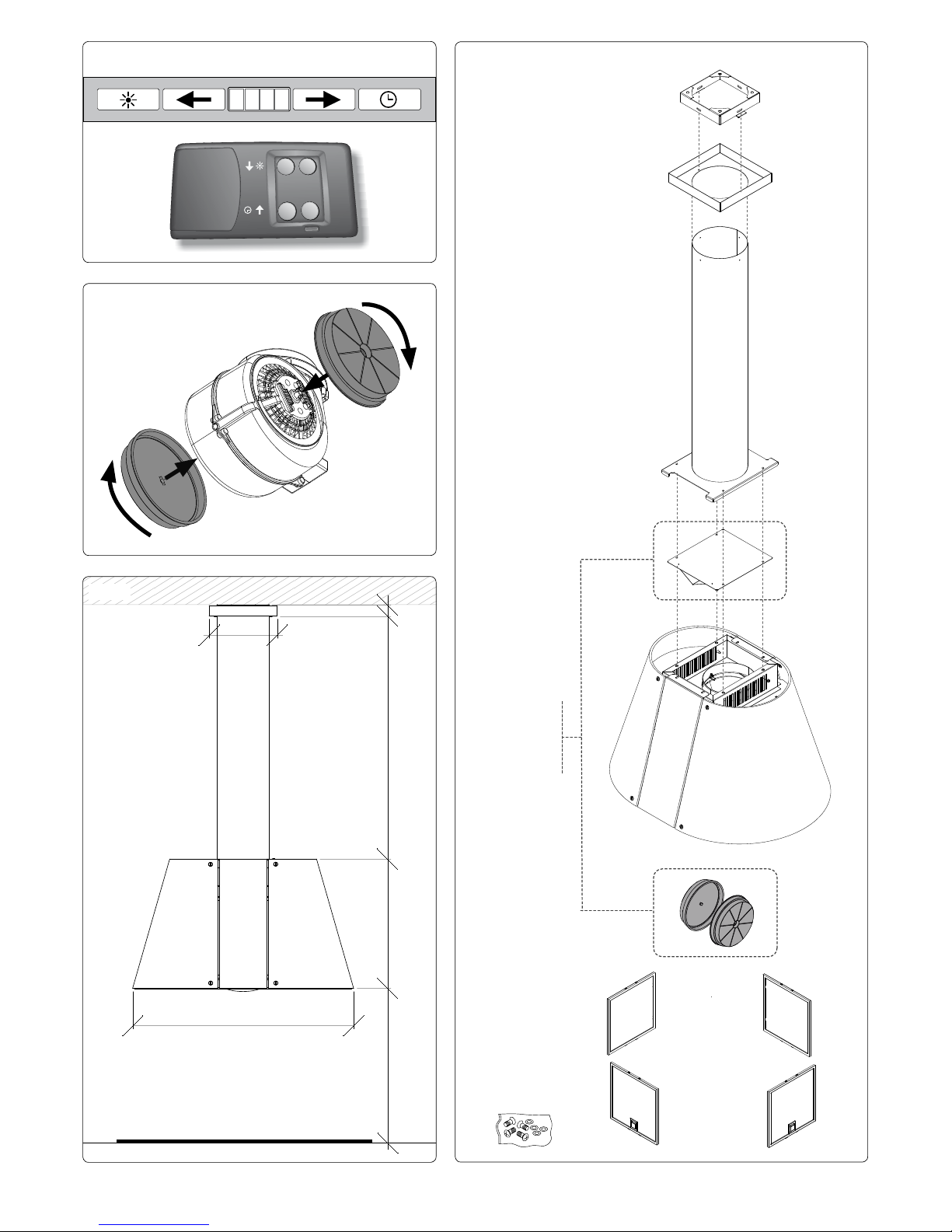
VERSIONE FILTRANTE
RECIRCULATING MODE
UMLUFTBETRIEB
MODE FILTRANTE
MODALIDAD FILTRANTE
FILTER
Fig.4
Z
E
D
G
M
L
H
Page 3
3LIOL1
3
VERSIONE FILTRANTE
RECIRCULATING MODE
UMLUFTBETRIEB
MODE FILTRANTE
MODALIDAD FILTRANTE
FILTER
Fig.8
Z
n
Fig.5
1
D
Fig.9
E
Fig.10
D
n
a
Fig.7
E
D
D
b
E
Fig.12
G
D
E
Fig.11
D
G
E
X
380 mm
650 - 750 mm
Fig.6
E
Page 4
4 3LIOL1
IT
MANUALE INSTALLAZIONE ED USO
GENERALITA'
Leggere attentamente il contenuto del presente
libretto in quanto fornisce importanti indicazioni
riguardanti la sicurezza di installazione, d’uso e
di manutenzione. Conservare il libretto per ogni
ulteriore consultazione.
ISTRUZIONI PER L’INSTALLAZIONE
Questo apparecchio è predisposto per essere
installato a softto sopra un piano di cottura e può
essere utilizzato in 2 modalità:
• ASPIRANTE: l'aria aspirata viene puricata
attraverso i ltri antigrasso metallici e convogliata
all'esterno attraverso un tubo.
• FILTRANTE: l'aria aspirata viene puricata
attraverso i ltri antigrasso e un ltro a carbone
attivo. L'aria viene inne rimessa nell'ambiente
interno. Per trasformare la cappa da versione
aspirante a versione ltrante, è necessario
richiedere al vostro rivenditore il kit ltrante e
seguire le istruzioni di montaggio.
A causa delle complessità dell’apparecchio si
consiglia che l’installazione venga effettuata
da personale specializzato, rispettando tutte
le normative vigenti ed in particolare quelle
relative allo scarico dell’aria da evacuare e al
collegamento elettrico. Il produttore declina
qualsiasi responsabilità per danni dovuti ad
una installazione non corretta o non conforme
alle regole dell’arte.
IMPORTANTE
• L’apparecchio deve essere installato ad un’altezza
minima di 650 mm dai fornelli elettrici, o 750 mm
dai fornelli a gas o misti
(Fig.3-6)
.
• Se dovesse essere usato un tubo di connessione
composto di due o più parti, la parte superiore
deve essere all’esterno di quella inferiore.
• Non collegare lo scarico della cappa ad un
condotto in cui circoli aria calda o utilizzato per
evacuare fumi degli apparecchi alimentati da
un’energia diversa da quella elettrica.
• Nel caso in cui nella stanza vengano utilizzati
sia la cappa che apparecchi non azionati da
energia elettrica si deve provvedere a creare una
areazione sufciente dell’ambiente.
• Per i vari montaggi utilizzare viti e tasselli ad
espansione idonei al tipo di muro (es. cemento
armato, cartongesso, ecc). Nel caso in cui le viti
e i tasselli siano forniti in dotazione con il prodotto
accertarsi che siano idonei per il tipo di parete su
cui deve essere ssata la cappa.
COMPONENTI > vedi Fig.4
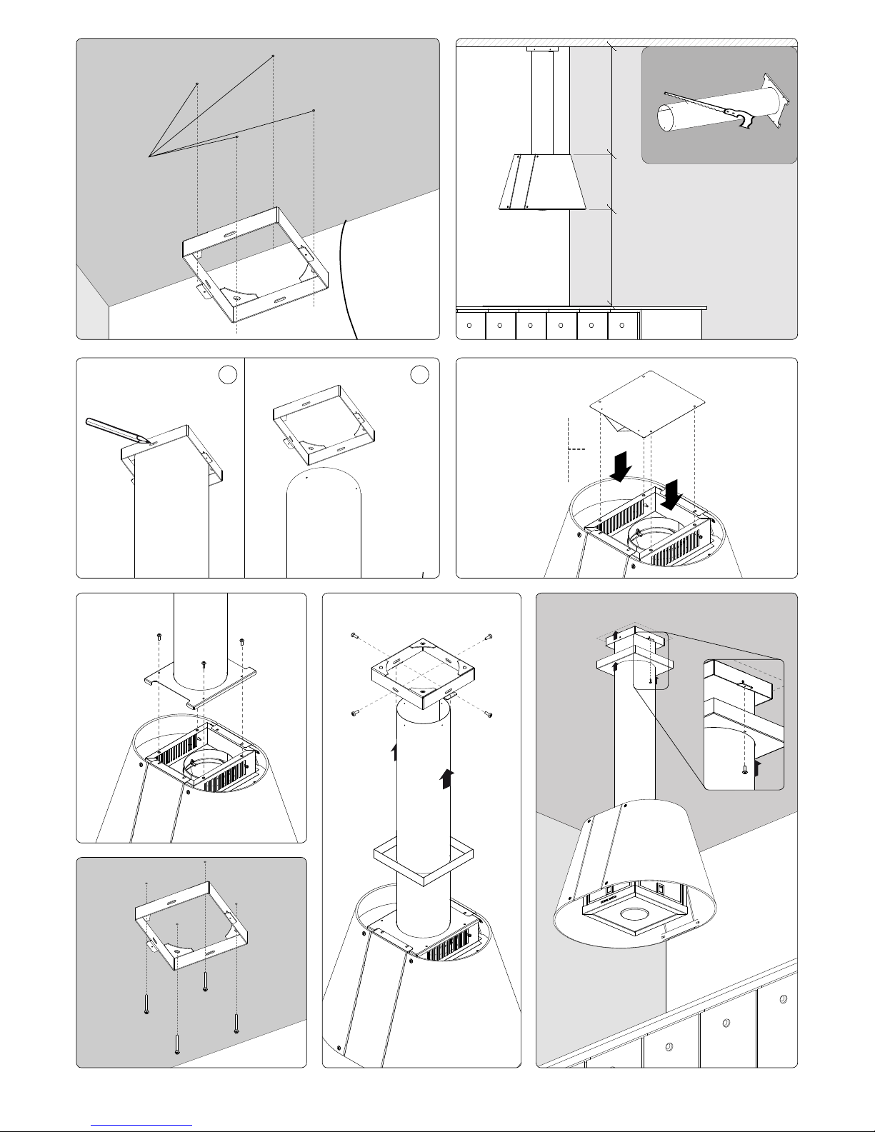
MONTAGGIO
• Praticare i fori 1 (Fig.5) per il ssaggio della
cappa al softto.
•
Tagliare il tubo di scarico E utilizzando un
attrezzo adeguato. La lunghezza del tubo deve
corrispondere alla misura X indicata in gura 6.
•Applicare la staffa Applicare la staffa D sul tubo E e segnare la
posizione dei fori da eseguire successivamente
(Fig.7a). Fare attenzione che la posizione della
staffa D rispetto al tubo E corrisponda a quella
indicata in g.3.
•Eseguire i fori di Ø 2 mm sul tubo Eseguire i fori di Ø 2 mm sul tuboØ 2 mm sul tubosul tubo E (Fig.7b).
• Posizionare il deettore d'aria Z sul corpo della
cappa(Fig.8).
ESEGUIRE LA SUDDETTA OPERAZIONE SOLO
PER MODALITA' FILTRANTE.
• Fissare il tubo E al corpo della cappa con le 4 viti
in dotazione (Fig. 9)
• Bloccare la staffa D al softto tramite i 4 fori 1 (Fig.
10) utilizzando le apposite viti del sacchetto H.
• Inserire il coperchio G all'interno del tubo E.
Sollevare la cappa inserendo il tubo E nella staffa
D. Fissare il tubo E sui lati della staffa D con le 4
viti in dotazione (Fig. 11).
• Alzare il coperchio G e ssare alla staffa D con le
2 viti in dotazione (Fig. 12).
CONNESSIONE ELETTRICA ALLA RETE
- Vericare che la tensione di rete sia adeguata a
quella richiesta par l’alimentazione della cappa
come indicato sulla targhetta applicata all’interno
dell’ apparecchio.
- Montare sul cavo una spina a norma e adeguata
al carico da sopportare oppure, nel caso di
collegamento diretto alla rete, interporre tra la rete
e l’apparecchio un interruttore bipolare a norma
e di potenza adeguata con apertura minima fra i
contatti di 3 mm.
CONTROLLO FUNZIONALE
Vericare l’accensione del motore a tutte le velocità
e l’illuminazione.
IT
IT
Page 5
3LIOL1
5
IT
IT
ISTRUZIONI PER L'USO
QUADRO COMANDI (Fig.1)
- Luce ON/OFF
- Accensione in 4°velocità (massima). Riduzione
velocità dalla 4° alla 1°velocità, poi lo
spegnimento.
- Display - mostra la velocità impostata (da 1 a 4)
- Accensione aspirazione in 1°velocità (minima).
Aumento aspirazione dalla 1° alla 4°velocità, poi
lo spegnimento.
- Timer- Attivazione del timer di autospegnimento
(10 minuti).
Telecomando (opzionale) (Fig.1)
SICUREZZA
• Non fare cucine alla amma sotto la cappa.
• Utilizzando delle friggitrici e’ necessario controllarle
costantemente perchè l’olio surriscaldato potrebbe
incendiarsi.
• Prima di procedere a qualsiasi operazione di pu-
lizia scollegare l’apparecchio dal collegamento
elettrico slando la spina o agendo sull’ interruttore generale.
• Nel caso in cui nella stanza vengano utilizzati
simultaneamente sia la cappa che altri apparecchi
non alimentati da energia elettrica, bisogna
provvedere ad areare il locale.
• Evitare fornelli accesi liberi (non utilizzati).
• Limitare l’uso della cappa a ciò che è stata
progettata: abbattere gli odori di cucina.
Non utilizzarla per altri impieghi.
• E’ consigliabile di far funzionare la cappa poco
prima di procedere a qualsiasi operazione di
cottura e lasciarla in funzione dopo la cottura per
almeno 10 minuti e comunque no a quando ogni
odore non sia scomparso.
MANUTENZIONE
Il buon funzionamento della cappa è condizionato
dall’assiduità con cui sono effettuate le operazioni
di manutenzione, in modo particolare, del ltro
antigrasso, e del ltro al carbone attivo. Pulire
frequentemente tutti i depositi sul ventilatore e sulle
altre superci, usando un panno inumidito con alcool
denaturato o detersivi liquidi neutri non abrasivi.
• Utilizzare solo ed esclusivamente un panno umido
e detersivo liquido neutro.
• Evitare panni e spugne bagnate, getti d’ acqua,
diluenti, solventi, alcol e sostanze abrasive.
ATTENZIONE
Prima di procedere a qualsiasi operazione di pulizia
scollegare l’apparecchio dal collegamento elettrico
slando la spina o agendo sull’ interruttore generale.
FILTRI ANTIGRASSO METALLICI (Fig.4M)
I ltri antigrasso hanno il compito di trattenere
le particelle grasse in sospensione nell’aria,
pertanto sono soggetti ad intasarsi in tempi variabili
relativamente all’uso dell’apparecchio.
In ogni caso, per prevenire il pericolo di eventuali
incendi, al massimo dopo 2 mesi è necessario pulire i
ltri eseguendo le seguenti operazioni:
• Togliere i ltri dalla cappa e lavarli con una soluzione
di acqua e detergente liquido neutro, lasciando
rinvenire lo sporco.
• Sciacquare abbondantemente con acqua tiepida e
lasciare asciugare.
I ltri possono essere lavati anche in lavastoviglie.
Dopo alcuni lavaggi si possono vericare delle
alterazioni del colore. Questo non dà diritto a reclamo
per l’eventuale sostituzione dei pannelli.
FILTRI AL CARBONE ATTIVO
(Fig.4L - Fig.2) Solo per versione ltrante
I ltri al carbone attivo servono per depurare l’aria
che verrà rimessa nell’ambiente. La saturazione del
carbone attivo dipende dall’uso più o meno prolungato
dell’apparecchio, dal tipo di cucina e dalla regolarità
con cui viene effettuata la pulizia del ltro antigrasso.
I ltri non sono lavabili o rigenerabili e devono essere
sostituiti ogni quattro mesi al massimo.
Per il estrarre il ltro carbone è necessario:
• smontare i ltri antigrasso metallici (Fig.4M).
• estrarre i 2 ltri carbone ruotandoli (Fig.2)
ILLUMINAZIONE
Per la eventuale sostituzione della lampada montate
bisogna:
• ruotare in senso antiorario il gruppo luce;
• slare il gruppo luce
• rimontare una lampada di uguali caratteristiche poichè
una di maggiore potenza potrebbe danneggiare
seriamente l’impianto elettrico.
DISMISSIONE DEGLI ELETTRODOMESTICI
La direttiva Europea 2002/96/CE sui riuti di
apparecchiature elettriche ed elettroniche (RAEE),
prevede che gli elettrodomestici non debbano
essere smaltiti nel normale usso dei riuti solidi
urbani. Gli apparecchi dismessi devono essere
raccolti separatamente per ottimizzare il tasso di
recupero e riciclaggio dei materiali che li compongono ed
impedire potenziali danni per la salute e l ambiente. Il simbolo
del cestino barrato è riportato su tutti i prodotti per ricordare gli
obblighi di raccolta separata. Per ulteriori informazioni, sulla
corretta dismissione degli elettrodomestici, i detentori potranno
rivolgersi al servizio pubblico preposto o ai rivenditori.
SI DECLINA OGNI RESPONSABILITÀ PER EVENTUALI DANNI
PROVOCATI DALLA INOSSERVANZA DELLE SUDDETTE
AVVERTENZE. LA GARANZIA NON E’ VALIDA NEL CASO DI
DANNI DERIVANTI DALLA INOSSERVANZA DELLE SUDDETTE
AVVERTENZE.
Page 6

6 3LIOL1
EN
USE AND INSTALLING INSTRUCTIONS
Carefully read the following important information
regarding installation safety and maintenance.
Keep this information booklet accessible for further
consultations.
INSTALLING INSTRUCTIONS
This hood has been arranged to be installed above
a cooktop. It can be used in 2 ways:
• EXHAUST MODE: the kitcken vapours are puried
by the metal anti-grease lters and carried outside
through a ducting system.
• RECIRCULATING MODE: the kitcken vapours
are puried by the metal anti-grease lters and
an activated carbon lter (sold separately), then
conveyed back into the kitchen.
In order to transform your cooker hood from the
exhaust version to the recirculating version, ask
your local retailer for the recircultating kit and
then carry out the enclosed installing instructions.
We suggest to have installation carried out
by qualied personnel, in compliance with all
the current regulations and in particular with
the ones concerning air exhaust and electrical
connection.
The manufacturer cannot be held liable for
damages caused by improper installation or
if it has not been carried out according to the
state-of-the-art.
SAFETY
• The appliance must be installed at a minimum
height of 650 mm from an electric cooker stove, or
750 mm from gas or combined cooker stoves (Fig.
6).
• If a connection tube composed of two parts is
used, the upper part must be placed outside the
lower part.
• Do not connect the cooker hood exhaust to the
same conductor used to circulate hot air or for
evacuating fumes from other appliances generated
by other than an electrical source.
• Take care when the cooker hood is operating
simultaneously with an open replace or burner
that depend on the air in the environment and are
supplied by other than electrical energy, as the
cooker hood removes the air from the environment
which a burner or replace need for combustion.
• The negative pressure in the environment must
not exceed 4 Pa (4x10 –5 bar).
• Provide adequate ventilation in the environment
for a safe operation of the cooker hood.
• Follow the local laws applicable for external air
evacuation.
INSTALLATION
Components > see Fig.4
Use screws and screw anchors suitable for wall
(e.g. reinforced cement, plasterboard) for the
mounting of the cooker hood. Where screws and
screw anchors are supplied ensure that they are
suitable for the type of wall where the cooker hood
is to be mounted.
ASSEMBLING THE COOKER HOOD
• Drill the holes 1 (Fig.5) for xing the cooker hood
to the ceiling.
• Cut the exhaust tube E with a suitable tool. The
lenght of the tube has to correspond to the X
measure as shown on gure n.6.
• Apply the xing clamp D on the tube E and
mark the position for the drillholes (Fig.7a). The
position of the support clamp D in respect to
the tube E has to be the same which is shown
on g. 3.
• Drill a hole of Ø 2 mm on the exhaust tube E
(Fig.7b).
• Position the air deviator Z on the body of the hood
(Fig.8). Carry out the above operation only for
recirculating mode.
• Fix the exhaust tube E to the body of the hood
using four screws from the accessories bag H
(Fig.9).
• Afx the xing clamp D to the ceiling via the holes
1
using the 4 long screws provided (Fig.10).
• Insert the lid G on the exhaust tube E.
Lift up the hood inserting the tube E on the
xing clamp D. Fix the tube to the clamp using 4
screws. (Fig.11)
• Lift up the lid G and x it to the clamp D using 2
screws (Fig.12).
ELECTRICAL CONNECTION
The appliance has been manufactured as a class
II, therefore no earth cable is necessary.
The connection to the mains is carried out as follows:
BROWN = L line BLUE = N neutral
If not provided, connect a plug for the electrical
load indicated on the description label. Where a
plug is provided, the cooker hood must be installed
in order that the plug is easily accessible.
An omnipolar switch with a minimum aperture of
3 mm between contacts, in line with the electrical
load and local standards, must be placed between
the appliance and the network in the case of direct
connection to the electrical network.
OPERATING CHECKS
Check lights and motor start-up on all speeds.
EN
Page 7

3LIOL1
7
EN
EN
USE INSTRUCTIONS
CONTROL PANEL (Fig.1)
- Light ON/OFF
- Switch on at 4th speed (maximum)
Speed reduction from 4th to 1st speed then
switch-off
-
Display - shows the set speed (from 1 to 4)
- Switch on at 1st speed (minimum). Intake
increase from 1st to 4th speed, then switchoff.
- Timer - Activation of the auto switch-off timer
(10 minutes).
Remote Control (Fig.1) optional
CLEANING AND MAINTENANCE
It is recommended to switch on the appliance
before cooking. It is also recommended to leave
the appliance in operation for 10 minutes after
cooking is terminated in order to completely
eliminate cooking vapours and odours.
The proper function of the cooker hood is
conditioned by the regularity of the maintenance
operations, in particular, the active carbon lter.
Clean the fan and other surfaces of the cooker hood
regularly using a cloth moistened with denatured
alcohol or non abrasive liquid detergent.
WARNING: unplug the appliance or switch
off the circuit breaker before carrying out
maintenance operations.
METAL ANTI-GREASE FILTERS (Fig.4M)
The metal anti-grease lters capture the grease
particles of the vapours that develop during cooking,
therefore they are subject to clogging according to
the frequency of the use of the appliance.
In order to prevent re hazard, it is recommendable to clean the lter every 2 months by carrying
out the following instructions:
• Remove the lters from the cooker hood and
wash them in a solution of water and neutral
liquid detergent, leaving to soak.
• Rinse thoroughly with warm water and leave to
dry.
The lters may also be washed in a dishwasher.
The aluminium panels may alter in colour after
several washes. This is not cause for customer
complaint nor replacement of panels.
ACTIVATED CARBON FILTERS (Fig.4L)
The activated carbon lters purify the kitchen
vapours, the air is then conveyed back into the
kitchen. The saturation of the active carbon lter
depends on the frequency of use of the appliance,
by the type of cooking and the regularity of cleaning
the anti-grease lters.
The lters are not washable nor re-useable and
must be replaced at maximum every four months.
To assemble the carbon lter it is necessary to:
- remove the metal anti-grease lters (Fig.4M)
- rotate the 2 carbon lters to remove them (Fig.2)
LIGHTING
In order to change the mounted lamps:
- rotate the light unit anti-clockwise;
- remove the light unit;
- Replace the lamp with one that has the same features because one with major power may cause
severe damage to the electrical system.
SAFETY INSTRUCTIONS
In certain circumstances electrical appliances
may be a danger hazard.
• The hood has been designed to remove the
kitchen smells; any other additional use shall be
regarded as non-intended.
• Areate the room if other appliances that are not
supplied by electrical power are being used while
the hood is on.
• Do not leave the cooker on if it is not being used.
• Do not ambé food directly under the cooker
hood to prevent the grease lter catching re due
to ames.
• Constantly check food frying to avoid that the
overheated oil may become a re hazard.
• Do not check the status of the lters while the
cooker hood is operating.
• Do not touch the light bulbs after appliance use.
DISPOSAL OF OLD ELECTRICAL APPLIANCES
The European Directive 2002/96/EC on Waste
Electrical and Electronic Equipment (WEEE),
requires that old household electrical
appliances must not be disposed of in the
normal unsorted municipal waste stream. Old
appliances must be collected separately in
order to optimise the recovery and recycling of the materials
they contain and reduce the impact on human health and
the environment.
The crossed-out dustbin symbol on the product reminds
you of your obligation regarding separated waste collection.
Consumers should contact their local public service or their
local dealer for more information on the correct disposal of
exhausted household appliances.
THE MANUFACTURER DECLINES ALL
RESPONSIBILITY FOR EVENTUAL DAMAGES
CAUSED BY BREAKING THE ABOVE WARNINGS.
THE WARRANTY IS NOT VALID IN THE CASE OF
DAMAGE CAUSED BY FAILURE TO COMPLY WITH
THE ABOVE WARNINGS.
Page 8

8 3LIOL1
Lesen Sie diese Bedienungsanleitung
bitte aufmerksam durch, da sie wichtige
Sicherheitshinweise hinsichtlich der Installation, dem
Gebrauch und der Wartung des Gerätes enthält.
Bewahren Sie die Bedienungsanleitung für mögliche
zukünftige Fragen oder Probleme bitte auf.
INSTALLATION
Das Gerät wurde als Dunstabzugshaube mit
Abluftbetrieb (die angesaugte Luft wird nach
außen abgeleitet) oder als Dunstabzugshaube
mit Umluftbetrieb (die Luft wird in den Raum
zurückgeleitet) entwickelt.
ABLUFTBETRIEB: Die abgesaugte Luft wird mithilfe
der metallenen Fettlter gereinigt und durch ein Rohr
nach außen geleitet.
UMLUFTBETRIEB: Die abgesaugte Luft wird mithilfe
der Fettlter und eines Aktivkohlelters (separat
verkauft) gereinigt und wieder in den Innenraum
geleitet.
Um die Haube in Umluft Version zu brauchen,
müssen Sie bei Ihrem Lieferanten das Umluft Set
kaufen und die sich darin bendenden Anleitungen
der Montage befolgen.
Auf Grund der Komplexität des Gerätes wird
empfohlen, die Installation durch Fachpersonal
unter Einhaltung der gültigen Bestimmungen
sowie im Besonderen der in Bezug auf die
Ableitung der abzuführenden Luft vornehmen zu
lassen und den elektrischen Anschluss.
Der Hersteller lehnt jegliche Haftung bei einer
falschen oder nicht fachgerechten Installation
ab.
SICHERHEITSHINWEISE
Das Gerät muss in einem Mindestabstand von 650
mm über einem Elektroherd und 750 mm über einem
Gas- oder kombinierten Herd installiert werden
(Abb.6). Falls ein Verbindungsrohr verwendet wird,
das aus zwei oder mehreren Teilen zusammengesetzt
ist, muss der obere Teil über den unteren gestülpt
werden. Auf keinen Fall darf das Abluftrohr der
Dunstabzugshaube an ein Rohr angeschlossen
werden, in dem warme Luft zirkuliert oder das zur
Entlüftung von Geräten verwendet wird, die an eine
andere Energiequelle als an Strom angeschlossen
sind. Vorsicht ist geboten, wenn gleichzeitig eine
Dunstabzugshaube und ein raumluftabhängiger
Boiler oder ein offenes Feuer in Betrieb sind, die
von einer anderen Energiequelle als Strom versorgt
werden, da die Dunstabzugshaube die Raumluft
absaugt, die auch der Boiler oder das Feuer zur
Verbrennung benötigen.
Der Unterdruck im Raum darf den Wert von 4 Pa (4 x
10-5bar) nicht übersteigen.
Um einen sicheren Betrieb der Dunstabzugshaube zu
gewährleisten, ist daher immer auf eine ausreichende
Belüftung des Raumes zu achten.
Bei der Ableitung der Luft nach außen müssen die
im jeweiligen Land geltenden Vorschriften beachtet
werden.
MONTAGE
BAUTEILE (Abb.4)
Für die Befestigung der Haube Schrauben und Dübel
gebrauchen, die geeignete sind je nach der Art des
Materials der Mauer (z.B. Zement, Gips Etc). Im Falle
die Schrauben und Dübel beim Produkt mitgeliefert
worden sind bitte prüfen, ob sie geeignet sind für die
Wand an welcher die Haube befestigt wird.
• Die Löcher 1 (Abb.5) für die Befestigung der
Abzugshaube an der Decke bohren.
• Das Auslassrohr E mit einem geeigneten Werkzeug
zuschneiden. Die Länge des Rohres muss dem in
Abbildung 6 angegebenen Maß X entsprechen.
• Den Bügel D auf das Rohr E auegen und die
Lage der danach zu bohrenden Löcher (Abb. 7a)
anzeichnen. Der Bügel D muss so auf dem Rohr E
liegen, wie in Abb. 3 angegeben.
• Die Löcher Ø2mm auf dem Rohr bohren (Abb. 7b).
• Die Umluftweiche Z auf das Gehäuse der
Abzugshaube geben (Abb.8). Diesen vorgang nur
beim umluftbetrieb ausführen.
• Das Rohr E mit den mitgelieferten vier Schrauben
(Abb.9) am Gehäuse der Abzugshaube befestigen.
• Den Bügel D an der Decke in den 4 Löchern
1
(Abb.10) befestigen und dabei die entsprechenden
Schrauben aus dem Beutel H verwenden.
• Den Deckel G ins Rohr E einführen. Die Abzugshaube
anheben und das Rohr E in den Bügel D schieben.
Das Rohr E an den Seiten des Bügels D mit den vier
mitgelieferten Schrauben (Abb.11) befestigen.
• Den Deckel G heben und mit den zwei mitgelieferten
Schrauben (Abb.12) am Bügel D befestigen.
ELEKTROANSCHLUSS
Das Küchenhaube gehört zur Geräteklasse II, daher
müssen keine Leitungen geerdet werden.
Der Anschluss an das Stromnetz ist folgendermaßen
durchzuführen:
BRAUN = L Leitung BLAU= Neutrale Linie
Falls nicht vorhanden, muss ein Normstecker mit
den auf dem Typenschild angegebenen Werten
an das Kabel angeschlossen werden. Wenn
die Dunstabzugshaube mit einem Netzstecker
ausgestattet ist, muss sie so installiert werden, dass
der Stecker gut zugänglich ist. Beim Direktanschluss
an das Stromnetz muss zwischen Gerät und
Stromnetz ein der Netzlast und den geltenden
Vorschriften entsprechender Mehrpolstecker mit einer
Mindestöffnung von 3 mm zwischen den Kontakten
installiert werden.
FUNKTIONSKONTROLLE
Überprüfen Sie das Einschalten des Motors bei den 4
Geschwindigkeiten sowie die Beleuchtung.
DE
BEDIENUNGS UND WARTUNGSANLEITUNG
Page 9

3LIOL1
9
DE
DE
abhängig, sowie von der Art der zubereiteten
Speisen und von der Regelmäßigkeit, mit welcher
die Fettlter gereinigt werden.
Zur Montage des Kohlelters ist Folgendes
erforderlich:
• Die metallenen Fettlter abmontieren (Abb.4M).
• Die Kohlenilter abmontieren (Abb.2)
BELEUCHTUNG
Im Falle einer eventuellen Auswechselung der
eingebauten Lampen wie folgt vorgehen:
- Die Lichtgruppe gegen den Uhrzeigersinn
drehen;
- Die Lichtgruppe herausnehmen.
- Bauen Sie eine Lampe mi t den gleichen
Eigenschaften ein, da eine höhere Leistung die
Elektroanlage beschädigen könnte.
VORSICHT!
Elektrogeräte können unter gewissen Umständen
gefährlich sein!
• Kontrollieren Sie niemals die Filter, wenn die
Dunstabzugshaube in Betrieb ist.
• Fassen Sie die Lämpchen nach längerem Betrieb
der Dunstabzugshaube nicht an.
• Es ist verboten, unter der Dunstabzugshaube
Speisen zu ambieren.
• Offenes Feuer ist unbedingt zu vermeiden, da
dieses die Filter beschädigen und einen Brand
verursachen kann.
• Kontrollieren Sie beim Frittieren die Speisen
ständig, um eine Entzündung des Öls zu
vermeiden.
• Vor jeglichen Wartungsarbeiten unbedingt den
Netzstecker aus der Steckdose entfernen.
AFBRAAK VAN DE ELEKTRISCHE
HUISHOUDAPPARATEN
De Europese Richtlijn 2002/96/CE over
de afbraak van elektrische en
elektronische apparaten (RAEE), voorziet
dat de huishoudelijke apparaten niet
samen met ongesorteerd stedelijk afval
mag worden verwijderd. De oude
apparaten moeten gescheiden worden ingezameld
om de materialen te kunnen hergebruiken en om
schade aan gezondheid en milieu te vermijden.
Het symbool met het doorgehaalde mandje,
weergegeven op alle producten, geeft aan dat het
product onderhevig is aan gescheiden inzameling.
Voor verdere inlichtingen over een correcte afbraak
van huishoudelijke apparaten neem contact op met
de speciale afdelingen of met de verkoper.
FÜR SCHÄDEN, DIE AUF DIE NICHTBEACHTUNG DER
OBEN GENANNTEN ANWEISUNGEN ZURÜCKZUFÜHREN
SIND, WIRD KEINERLEI VERANTWORTUNG ÜBERNOMMEN
UND DIE GARANTIE ERLISCHT SOFORT.
BEDIENUNG
Es wird empfohlen, die Dunstabzugshaube vor
eventueller Zubereitung der Speisen einzuschalten.
Es wird weiterhin empfohlen, das Gerät nach
Beendigung des Kochvorganges noch 10 Minuten
weiterlaufen zu lassen, um die vollständige
Entlüftung der Kochdämpfe zu gewährleisten.
Das einwandfreie Funktionieren der
Dunstabzugshaube hängt entscheidend von
der Sorgfalt ab, mit der die Wartungsarbeiten
durchgeführt werden, insbesondere die des
Fettlters und die des Aktivkohlelters.
STEUERPULT (Abb.1)(Abb.1)
- Licht EIN/AUS- Licht EIN/AUS
- Einschaltung in 4. Geschwindigkeit (maximale).- Einschaltung in 4. Geschwindigkeit (maximale).
Geschwindigkeitsreduzierung von der 4. zur 1.
Geschwindigkeit, danach Ausschaltung.
- Display - Anzeige der eingestellten
Geschwindigkeit (von 1 bis 4)
- Einschaltung Absaugung in 1. Geschwindigkeit- Einschaltung Absaugung in 1. Geschwindigkeit
(minimale). Erhöhung der Absaugung von
der 1. zur 4. Geschwindigkeit, danach
Ausschaltung.
- Timer - Aktivierung des Timers zur- Timer - Aktivierung des Timers zur
Ausschaltung (10 Minuten).
Fernbedienung als Sonderausstattung (Abb.1)Abb.1)
FETTFILTER AUS METALL (Abb.4M)
Die Fettlter haben die Aufgabe, die Fettpartikel
in der Luft zu binden; die Sättigung der Filter
hängt daher von der Häugkeit ab, mit der die
Dunstabzugshaube betrieben wird.
Um eine mögliche Brandgefahr zu verhindern,
muss der Filter auf jeden Fall spätestens alle zwei
Monate wie folgt gereinigt werden: Entnehmen
Sie die Filter aus der Dunstabzugshaube und
waschen Sie sie mit einem Gemisch aus Wasser
und üssigem Neutralreiniger ab.
Wenn notwenig, lassen Sie die Verschmutzungen
kurz einweichen.
Gründlich mit lauwarmem Wasser abspülen und
abtrocknen lassen. Sie können die Filter auch in
der Geschirrspülmaschine reinigen.
Nach mehrmaligem Waschen der Aluminiumlter
können Farbveränderungen auftreten.
Daraus resultiert jedoch kein Anspruch auf einen
kostenlosen Ersatz dieser Teile des Geräts.
AKTIVKOHLENFILTER (Abb.4L)
(für Umluftversion) einzeln verkäuich
Die Aktivkohlelter dienen dazu, die Luft zu
reinigen, die wieder in den Raum zurückgeführt
wird. Diese Filter sind weder waschbar noch wieder
verwertbar und müssen spätestens alle vier Monate
ausgewechselt werden.
Die Sättigung der Aktivkohle ist von der mehr oder
weniger langen Benutzung der Küchenhaube
Page 10

10 3LIOL1
INSTRUCTIONS
Lire attentivement le contenu du mode d’emploi
puisqu’il fournit des indications importantes
concernant la sécurité d’installation, d’emploi
et d’entretien. Le conserver pour d’ultérieures
consultations.
INSTRUCTIONS POUR L’INSTALLATION
L’appareil peut être utilisé en deux modes:
ASPIRANTE: l’air aspiré est purié à travers les
ltres anti-graisse métalliques et acheminé vers
l’extérieur à travers un tuyau.
FILTRANTE: l’air aspiré est purié à travers
les ltres anti-graisse et un ltre à charbon actif
(vendu à part). L’air est nalement réintroduit
dans l’environnement interne.
Pour transformer la
hotte de la version aspirante à la version ltrante,
demander à votre revendeur le kit ltrante et
suivre les instructions de montage.
À cause de la complexités de l'appareil, on
conseille de le faire installer par du personnel
spécialisé, dans le respect de toutes les
normes en vigueur et en particulier celles qui
concernent le déchargement de l'air à évacuer
et la connexion électrique.
Le fabriquant décline toute responsabilité pour
les dommages dus à une installation erronée ou
non conforme aux règles de l'art.
SÉCURITÉ
L’appareil doit être installé à une hauteur minimale
de 650 mm des réchauds électriques, ou 750 mm
des réchauds à gaz ou mixtes (Fig.6).
S’il doit être utilisé un tuyau de connection composé
de deux ou plusieurs parties, la partie supérieure
doit être à l'extérieur de celle inférieure.
Ne pas relier le tuyau d’échappement de la hotte
à un conduit dans lequel circule de l’air chaud ou
employé pour évacuer les fumées des appareils
alimentés par une énergie différente de celle
électrique.
Attention, lorsque dans la même pièce vous utilisez
simultanément la hotte à évacuation avec un brûleur
ou une cheminée alimentés par une énergie autre
que l’électricité, vous pouvez créer un problème
«d’inversion de ux».
Dans ce cas la hotte aspire l’air nécessaire à leur
combustion. La dépression dans le local ne doit pas
dépasser les 4 Pa (4 x 10⁻⁵ bar).
Pour un fonctionnement en toute sécurité, n’oubliez
pas de prévoir une ventilation sufsante du local.
Pour l’évacuation vers l’extérieur, veuillez vous
référer aux dispositions en vigueur dans votre
pays.
INSTALLATION
Composants > voir Fig.4
Pour les différents montages, utiliser les vis et
chevilles à expansion correspondant au type du
mur (ex béton armé, plâtre, etc.). Dans le cas où
les vis et chevilles sont fournies d’origine avec le
produit, vérier qu’elles correspondent bien au type
de mur sur lequel doit être montée la hotte.
MONTAGE
• Percer les trous 1 (Fig.5) pour la xation de la
hotte au plafond.
• Couper le conduit d’évacuation E à l’aide d’un outil
adéquat. La longueur du conduit doit correspondre
à la longueur X indiquée dans la gure 6.
• Placer le support de xation D sur le conduit E
et marquer l’emplacement des trous à percer
(Fig.7a). Veiller à ce que la position du support
D par rapport au conduit E corresponde bien à la
position indiquée dans la gure 3.
• Percer des trous de 2mm de diamètre sur le
conduit E (Fig.7b).
• Poser le déecteur d’air Z sur la hotte, comme
indiqué dans la gure 8. Cette opération est
réservée à une installation de la hotte en mode
ltrante.
• Fixer le conduit E à la hotte en utilisant les 4 vis
fournies (Fig. 9)
• Fixer le support D au plafond en serrant les vis du
sachet H dans les quatre trous 1 (Fig. 10).
• Glisser le couvercle G autour du conduit E.
Soulever la hotte en introduisant le conduit E dans
le support D. Fixer le conduit E sur les bords du
support D à l’aide des 4 vis fournies (Fig. 11).
• Lever le couvercle G et le xer au support D à
l’aide des 2 vis fournies (Fig. 12).
CONNEXION ÉLECTRIQUE
L’appareil est construit en classe II, pour cela aucun
câble ne doit être connecté avec la prise terre.
La connection avec le réseau électrique doit être
exécutée comme suit:
MARRON= L ligne BLEU= N neutre
Si elle n’a pas été prévue, monter sur le câble
une che normalisée pour la charge indiquée sur
l'étiquette des caractéristiques. Si elle est dotée d’une
che, la hotte doit être installée en sorte que la che
soit accessible. En cas de connection directe avec
le réseau électrique, il est nécessaire d’interposer
entre l’appareil et le réseau un interrupteur
omnipolaire avec une ouverture minimale entre
les contacts de 3 mm, proportionnel à la charge et
correspondant aux normes en vigueur.
CONTROLE FONCTIONNEL
Vérier l’allumage du moteur dans les 4 vitesses et
l’illumination.
FR
Page 11

3LIOL1
11
FR
DE
EMPLOI
TABLEAU DE COMMANDES (Fig.B)
- Éclairage ON /OFF
- Allumage en 4e vitesse (maximale).
Réduction de la vitesse de la 4e à la 1e
vitesse, puis extinction.
-
Écran - afche la vitesse programmée (de 1 à 4).
- Allumage de l’aspiration en 1e vitesse
(minimale). Augmentation de l’aspiration de
la 1e à la 4e vitesse, puis extinction.
- Minuterie - Mise en service de la minuterie
d’auto-extinction (10 minutes).
Télécommande optionnelle (Fig.1)
ENTRETIEN
Nous vous recommandons de mettre la hotte en
route avant de commencer à cuisiner.
Le bon fonctionnement de la hotte est lié à la
fréquence des opérations d'entretien, et plus
particulièrement à l’entretien du ltre anti-graisse et
du ltre au charbon actif.
FILTRES ANTIGRAISSE METALLIQUES
(Fig.4M)
Les ltres anti graisse metalliques ont pour rôle de
retenir les particules grasses en suspension dans
l’air. Ils peuvent donc se boucher plus ou moins
rapidement selon l’usage de la hotte.
Dans tous les cas, pour prévenir un éventuel risque
d’incendie, il est nécessaire de nettoyer au moins
tous les deux mois le ltre en suivant les indications
suivantes:
- Retirer les ltres de la hotte et les laver avec
de l’eau et un détergent liquide neutre, laisser la
saleté se décoller.
- Rincer abondamment à l’eau tiède et laisser
sécher.
Les ltres peuvent également être lavés dans le lave
vaisselle. Après plusieurs lavages des panneaux en
aluminium, on peut constater un changement de leur
couleur. Ceci n’ouvre pas droit à réclamation an
d’obtenir un éventuel changement des panneaux.
FILTRES AU CHARBON ACTIF
(Fig.4L)(seulement pour le mode ltrante)
Vendu séparément
Les ltres au charbon actif servent à ltrer l’air qui
sera rejeté dans la pièce.
Les ltres ne sont ni lavables ni régénérables
et doivent être changés tous les trois mois au
maximum.
La saturation du charbon actif dépend de l’utilisation
plus ou moins prolongée de l’appareil, du type de
cuisine effectué et de la régularité avec laquelle est
effectué le nettoyage du ltre anti graisse.
Pour le démontage du ltre à charbon il faut:
• démonter les ltres anti-graisse métalliques
(Fig.4M)
• Tourner les ltres au charbon pour les retirer
(Fig.2).
ILLUMINATION
Pour un éventuel remplacement des lampes
montées, il faut:
• Tourner le groupe lumière dans le sens inverse aux
aiguilles d’une montre;
• Dégager le groupe lumière;
• Remonter une ampoule avec les mêmes
caractéristiques car une ampoule de plus grande
puissance pourrait gravement endommager
l’installation électrique.
CONSEILS POUR LA SÉCURITÉ
• Dans des circonstances déterminées les
électroménagers peuvent être dangereux.
• Ne pas contrôler les ltres pendant que la hotte
est en fonctionnement.
• Ne pas toucher les lampes après un emploi
prolongé de l’appareil.
• ll est interdit de cuir les aliments à la amme sous
la hotte.
• Eviter la amme libre, parce qu'elle est nuisible
pour les ltres et dangereuse pour les incendies.
• Contrôler constamment les aliments frits pour
éviter que l’huile surchauffée prenne feu.
• Avant d’effectuer n’importe quel entretien
déconnecter la hotte durés eau électrique.
ENLèVEMENT DES APPAREILS MÉNAGERS
USAGÉS
La Directive Européenne 2002/96/EC sur les
Déchets des Equipements Electriques et
Electroniques (DEEE), exige que les appareils
ménagers usagés ne soient pas jetés dans le
flux normal des déchets municipaux. Les
appareils usagés doivent être collectés
séparément an d’optimiser le taux de récupération et le
recyclage des matériaux qui les composent et réduire
l’impact sur la santé humaine et l’environnement. Le
symbole de la “poubelle barrée” est apposée sur tous les
produits pour rappeler les obligations de collecte séparée.
Les consommateurs devront contacter les autorités locales
ou leur revendeur concernant la démarche à suivre pour
l’enlèvement de leur vieil appareil.
ON DÉCLINE TOUTE RESPONSABILITÉ POUR
LES ÉVENTUELS DÉGÂTS PROVOQUÉS PAR
L’INOBSERVATION DES SUSDITES INSTRUCTIONS.
LA GARANTIE N’EST PAS VALABLE EN CAS DE
DOMMAGES PROVOQUES PAR LE NON RESPECT DES
MISES EN GARDE CITEES CI-DESSUS.
Page 12

12 3LIOL1
INSTRUCCIONES
Lea atentamente el contenido del presente libro de
instrucciones pues contiene indicaciones importantes
para la seguridad en la instalación, el uso y el
mantenimiento. Consérvelo para un posible consulta
posterior.
INSTRUCCIONES PARA LA INSTALACIÓN
El aparato puede ser usado en 2 modalidades:
• ASPIRANTE: el aire aspirado es puricado a
través de los ltros anti grasa metálicos y expulsado
al exterior a través de un tubo.
• FILTRANTE: el aire aspirado es puricado a
través de los ltros anti grasa y un ltro de carbón
activo (se vende por separado), el aire vuelve a entra
en el ambiente interno.
Para transformar la campana
de versión aspirante a versión ltrante, solicite a su
proveedor el kit ltrante y seguir las instrucciones de
montaje.
Debido a la complejidad del aparato, se
recomienda que la instalación sea efectuada por
personal especializado, respetando todas las
normativas vigentes y en particular la relativa a la
evacuación de aire y a la conexión eléctrica.
El fabricante no se responsabiliza de ningún
daño ocasionado por una instalación incorrecta
o que no se lleve a cabo conforme a las reglas
actuales.
SEGURIDAD
Debe instalarse el aparato a una altura mínima de
650 mm de las hornillas eléctricas, o a una altura de
750 mm para las hornillas a gas o mixtas (Fig.6). Si
debe usarse un tubo de conexión compuesto de dos
o más partes, la parte superior debe estar fuera de la
parte inferior. No conecte la descarga de la campana
a un conducto en el que circule aire caliente o que
sea utilizado para evacuar los humos de aparatos
alimentados por una energía que no sea eléctrica.
Preste atención si funcionan contemporáneamente
una campana aspirante y un quemador o una
chimenea que toman el aire del ambiente y están
alimentados por energía que no sea eléctrica, pues la
campana aspirante toma del ambiente el aire que el
quemador o la chimenea necesitan para la combustión.
La presión negativa del local no debe superar los 4
Pa (4 x 10⁻⁵ bares). Para un funcionamiento seguro,
realice primero una adecuada ventilación del local.
Para la evacuación externa, aténgase a las
disposiciones vigentes en su país.
INSTALACIÓN DE LA CAMPANA
Componentes > Fig.4
Para los distintos montajes utilice tornillos y escarpias
de expansión adecuados al tipo de pared (ejemplo
hormigón, cartón-yeso, etc). En caso de que los
tornillos y las escarpias vengan adjuntos en el producto
asegúrese de que sean adecuados para el tipo de
pared donde se va a colocar la campana.
MONTAJE
• Realizar los oricios 1 (Fig.5) para la jación de la
campana al techo.
• Cortar el tubo de descarga E utilizando una
herramienta adecuada. La longitud del tubo debe
corresponder a la medida X indicada en la gura 6.
• Aplicar el soporte D en el tubo E y marcar la posición
de los oricios que se van a realizar a continuación
(Fig.7a). Prestar atención a que la posición del
soporte D respecto al tubo E corresponda a la
indicada en la g.3.
• Efectuar los oricios de Ø 2 mm en el tubo E
(Fig.7b).
• Colocar el deector de aire Z en el cuerpo de
la campana (Fig.8). Realizar dicha operación
únicamente para la modalidad ltrante.
• Fijar el tubo E al cuerpo de la campana con los 4
tornillos suministrados (Fig. 9)
• Bloquear el soporte D en el techo mediante los
4 oricios 1 (Fig. 10) utilizando los respectivos
tornillos de la bolsita H.
• Introducir la tapa G en el tubo E. Levantar la
campana introduciendo el tubo E en la mordaza D.
Fijar el tubo E en los lados del soporte D con los 4
tornillos suministrados (Fig. 11).
• Levantar la tapa G y jarla en el soporte D con los 2
tornillos suministrados (Fig. 12).
INSTALACIÓN ELÉCTRICA
El aparato está construido en clase II, por lo tanto no
se debe conectar ningún cable a la toma de tierra. La
conexión a la corriente eléctrica debe realizarse de la
siguiente manera:
MARRON= L línea. AZUL= N neutro.
Si no está incluido, monte en el cable un enchufe
normalizado para la carga indicada en la etiqueta de
las características.
Si está provista de enchufe, coloque la campana de tal
manera que el enchufe quede en un sitio accesible.
En caso de conexión directa a la corriente eléctrica,
es necesario interponer entre el aparato y la red un
interruptor omnipolar con abertura mínima de 3 mm,
adecuado a la carga y que responda a las normas
vigentes.
CONTROL FUNCIONAL
Verique que el motor funcione en las 4 velocidades
y con la iluminación.
ES
Page 13

3LIOL1
13
FR
ES
INSTRUCCIONES PARA EL USO
PANEL DE MANDOS (Fig.1)
- Luz ON/OFF
- Encendido en 4° velocidad (máxima).
Reducción velocidad de la 4° a la 1° velocidad,
después el apagado.
- Display - muestra la velocidad programada
(de la 1 a 4)
- Encendido aspiración en 1° velocidad
(mínima). Aumento aspiración de la 1° a la
4° velocidad, después el apagado.
- Temporizador - Activación del temporizador
de apagado automático (10 minutos)
Control remoto opcional (Fig.1)
MANTENIMIENTO
El buen funcionamiento de la campana depende
de la asiduidad con la cual se realicen las
operaciones de mantenimiento, sobre todo, del
ltro antigrasa, o del ltro al carbón activo.
Limpie frecuentemente todos los restos de grasa
del ventilador y de las otras supercies usando
un paño humedo con alcohol etilico o detergentes
líquidos neutros no abrasivos.
FILTROS ANTIGRASA METÁLICOS
(Fig.4M)
Los ltros antigrasa sirven para retener las
partículas de grasa en suspensión en el aire, por
lo tanto se pueden obstruir en un espacio que
depende del uso que se haga del aparato.
De todas formas para evitar el peligro de posibles
incendios, como máximo cada dos meses es
necesario limpiar el ltro observando las siguientes
operaciones:
- Quite los ltros de la campana y lávelos con una
solución de agua y detergente liquido neutro
dejando ablandar la suciedad.
- Aclare con abundante agua templada y deje
secar. Se pueden lavar también los ltros en el
lavavajillas.
Después de algunos lavados los paneles de
aluminio se puede vericar en los paneles de
aluminio posibles alteraciones del color.
Esto no da opción a reclamaciones para una
posible sustitución de los paneles.
FILTRO DE CARBÓN ACTIVO (Fig.4L)
(sólo para la modalidad ltrante)
Los ltros al carbón activo sirven para depurar
el aire que volverá a circular en el ambiente.
Los ltros no son lavables o reciclables y deben
ser cambiados máximo cada cuatro meses.
La saturación del carbón activo, depende del
uso mas o menos prolongado del aparato, da el
tipo de cocina y de la regularidad con la cual se
efectúe la limpieza del ltro antigraso.
Para el montaje del ltro es necesario:
• desmontar los ltros antigrasa metálicos
(Fig.4M).
• Extraer los ltros de carbón tornándolos (Fig.2).
ILUMINACION
Si usted tiene que cambiar las lámparas tiene que
realizar lo siguiente:
- gire in sentido contrario a las agujas del reloj el bloque
de la luz.
- saque el bloque de la luz.
- Vuelva a montar una lámpara que tenga
características iguales pues una de mayor
potencia podría dañar seriamente la instalación
eléctrico.
ATENCIÓN !
En determinadas circunstancias los
electrodomésticos pueden ser peligrosos.
• No intente controlar los ltros cuando la
campana esté funcionando.
• No toque las lámparas después de un uso
prolongado del aparato.
• Está prohibido cocinar alimentos a la llama
debajo de la campana.
• Evite las llamas libres, pues resultan perjudiciales
para los ltros y pueden provocar incendios.
• Controle en todo momento los alimentos fritos
para evitar que el aceite caliente prenda fuego.
• Antes de realizar cualquier operación de
mantenimiento desconecte la campana de la
corriente eléctrica.
ELIMINACION DE LOS ELECTRODOMESTICOS
La regla Europea 2002/96/CE sobre los
desperdicios de los aparatos eléctricos y
electrónicos (RAEE), provee que los
electrodomésticos no deben ser eliminados
en el normal ujo de los desperdicios sólidos
urbanos. Los aparatos para desechar deben
ser recogidos separadamente para optimizar la taza de
recuperación y de reciclaje de los materiales que los
componen y para evitar potenciales daños para la salud y
el ambiente. El símbolo del cesto de basura tachado se
encuentra en todos los productos, para recordar las
obligación del recogido separado. Para ulteriores
informaciones, sobre la correcta eliminación de los
electrodomésticos, el comprador se puede dirigir al
servicio publico propuesto o a el vendedor.
EL FABRICANTE NO SE HACE RESPONSABLE DE LOS
DAÑOS PRODUCIDOS POR EL INCUMPLIMIENTO DE
ESTAS ADVERTENCIAS.
LA GARANTÍA NO ES VÁLIDA EN EL CASO DE DAÑOS
PROVOCADOS POR EL IRRESPETO DE DICHAS
ADVERTENCIAS.
Page 14

14 3LIOL1
INSTRUCTIES
Lees deze handleiding aandachtig door zij bevat
belangrijke inlichtingen over de veiligheid, de
installatie, het gebruik en het onderhoud.
Bewaar deze handleiding voor verdere
raadpleging.
INSTRUCTIES VOOR DE INSTALLATIE
Het apparaat kan op 2 manieren worden gebruikt:
AFZUIGING: de aangezogen lucht wordt
gezuiverd door de metalen antivetlters en via een
buis naar buiten afgevoerd.
FILTER: de aangezogen lucht wordt gezuiverd
door de metalen antivetlters en door een
(afzonderlijk verkocht) actief koolstoflter en wordt
tenslotte opnieuw in het vertrek afgegeven.
Om
het apparaat van afzuigend apparaat tot lterend
apparaat om te zetten vraag aan Uw verkoper om
koolstoflters en volg de montage instructies.
Wegens de complexiteit van het toestel is het
aangeraden dat de installatie ervan wordt
uitgevoerd door bekwame vaklieden, die alle
van kracht zijnde voorschriften respekteren
en in het bijzonder diegenen wat betreft de
uitlaat die de lucht moet evacueren en op de
elektrische aansluiting. De producent kan niet
verantwoordelijk gesteld worden voor welke
schade ook die veroorzaakt is door het niet
correct of overeenstemmend met de regels van
het vakmanschap installeren van de afzuigkap.
INSTALLATIE
Het toestel moet geïnstalleerd worden op een
minimale hoogte van 650 mm vanaf de elektrische
kookplaat en 750 mm vanaf een gaskookplaat
of een combi kookplaat (Afb.6). Indien een(Afb.6). Indien een. Indien een
verbindingspijp gebruikt wordt die uit twee of meer
delen bestaat, dan moet het bovenste gedeelte
aan de buitenkant van het onderste gedeelte zitten.
Sluit de afvoer van de kap niet op een kanaal aan
waarin warme lucht circuleert of dat gebruikt wordt
voor het afvoeren van rook van apparaten die door
een andere energiebron dan elektrische energie
gevoed worden.
Gebruik, voor de verschillende montages,
schroeven en expansiepluggen die geschikt zijn
voor het type muur (bijv. cement, gipskarton enz.).
Indien schroeven en pluggen met het product zijn
meegeleverd controleer of deze geschikt zijn voor
het muurtype waaraan de kap bevestigd moet
worden.
VEILIGHEIDSVOORSCHRIFTEN
Let op als tegelijkertijd een afzuigkap en een brander
of haard functioneren die afhankelijk zijn van de
omgevingslucht en gevoed worden door een andere
energiebron dan de elektrische energie, omdat de
kap tijdens het afzuigen de lucht die de brander
of haard nodig heeft voor de verbranding aan de
omgeving onttrekt. De negatieve druk in de ruimte
mag niet de 4 Pa (4 x 10⁻⁵ bar) overschrijden.
Voor een veilige werking, dient u de ruimte goed te
ventileren. Voor het afvoeren naar buiten moet u
zich aan de geldende voorschriften houden die in
uw land van toepassing zijn.
COMPONENTEN (Afb.4)
MONTAGE
• Boor gaten 1 (Afb. 5) om de kap aan het plafond
te bevestigen.
• Zaag afvoerbuis E door met een geschikt werktuig.
De lengte van de buis moet overeenkomen met
maat X die aangeduid wordt in afbeelding 6.
• Breng beugel D aan op buis E en markeer de positie
van de gaten die daarna geboord moeten worden
(Afb. 7a). Zorg ervoor dat de positie van beugel D
ten opzichte van buis E overeenkomt met de positie
die aangeduid wordt in afb. 3.
• Boor de gaten met Ø 2 mm op buis E (Afb. 7b)
• Breng luchtdeector Z in positie op het hoofddeel
van de kap (Afb. 8). Voer deze handeling alleen
uit voor de lterversie.
• Bevestig buis E op het hoofddeel van de kap met
de 4 bijgeleverde schroeven (Afb. 9).
• Zet beugel D vast aan het plafond met behulp van
de 4 gaten 1 (Afb. 10) en de betreffende schroeven
van zakje H.
• Plaats deksel G op buis E. Til de kap op en plaats
buis E in beugel D. Zet buis E met de 4 bijgeleverde
schroeven vast op de zijden van beugel D (Afb. 11).
• Til deksel G op en zet deze met de 2 bijgeleverde
schroeven vast op beugel D (Afb. 12).
ELEKTRISCHE AANSLUITING
Het toestel is gemaakt voor klasse II, het snoer
hoeft derhalve niet op een geaard stopcontact
aangesloten worden. De aansluiting op het
elektriciteitsnet moet als volgt gebeuren:
BRUIN: L lijn BLAUW: N neutraal
Als deze niet reeds is voorzien, installeer een
stekker die genormaliseerd is voor de aangegeven
elektrische spanning. Als het toestel van stekker
is voorzien moet de kap zodanig geïnstalleerd
worden dat de stekker goed bereikbaar is. In
geval van een rechtstreekse aansluiting op het
elektriciteitsnet plaats, tussen het apparaat en het
voedingsnet, een meerpolige schakelaar met een
minimale opening tussen de contacten van 3 mm,
deze moet berekend zijn op de belasting en moet
aan de geldende voorschriften voldoen.
FUNCTIONELE CONTROLE
Steek het apparaat in gang en controleer of de 4
snelheidsstanden en de verlichting wel degelijk
werken.
NL
Page 15

3LIOL1
15
NL
FR
GEBRUIK
BEDIENINGSPANEEL (Afb.1)
- Licht ON/OFF- Licht ON/OFF
- Inschakeling in 4de snelheid (maximum).- Inschakeling in 4de snelheid (maximum).
Afname snelheid van 4de naar 1e snelheid,
vervolgens uitschakeling.
- Display - toont de instelde snelheid (van 1 tot- Display - toont de instelde snelheid (van 1 tot
4).
- Inschakelingafzuiging bij1e snelheid (minimum).- Inschakeling afzuiging bij 1e snelheid (minimum).
Verhoging afzuiging van 1e naar 4de snelheid,
vervolgens uitschakeling.
- Timer - activeringvande timer voorautomatische- Timer - activering van de timer voor automatische
uitschakeling (10 minuten).
Optionele afstandsbediening (Afb.1.)
ONDERHOUD
We raden aan de kap aan te zetten voordat u begint
te koken. We raden aan de kap nog 10 minuten
aan te laten staan nadat het eten bereid is, voor
een volledige afvoer van de verzadigde lucht.
De goede werking van de kap hangt af van een
regelmatig en grondig onderhoud, in het bijzonder
van het vetlter en van het koolstoflter. Verwijder
regelmatig de aanslag op de ventilator en op de
andere oppervlakken, gebruik een vochtig doek
met gedenatureerd alcohol of neutrale vloeibare
reinigingsmiddelen, gebruik geen schuurmiddelen.
METALEN VETFILTERS (Afb.4M)
De vetlters houden de vetdeeltjes die in de lucht
circuleren vast en raken daarom oververzadigd op
onregelmatige tijden, afhankelijk van een al dan niet
intensief gebruik van het toestel.
In ieder geval, om brandgevaar te voorkomen,
moet het vetlter hoogstens om de 2 maanden
gereinigd worden door de volgende handelingen uit
te voeren:
- De lters uit de kap halen en reinigen in een sop
van water en neutraal wasmiddel, op deze wijze het
vuil verwijderend.
- Grondig met lauw water afspoelen en laten drogen.
Deze lters kunnen ook in de vaatwasmachine
gereinigd worden.
Na verschillende wasbeurten van de aluminium
platen, kunnen kleurveranderingen plaatsvinden.
Dit geeft echter niet het recht op de vervanging van
de platen.
KOOLSTOFFILTERS (Afb.4L)
(alleen voor lterend apparaat)
De koolstoflters zuiveren de lucht die weer in de
ruimte teruggevoerd wordt. De lters kunnen niet
gewassen of opnieuw gebruikt worden en moeten
hoogstens om de vier maanden vervangen worden.
De verzadiging van de koolstof hangt af van het
gebruik van de kap, van het type keuken en van de
regelmaat waarmee het vetlter schoongemaakt
wordt. Handel als volgt voor de montage van hetHandel als volgt voor de montage van het
koolstoflter:
• Demonteer de metalen antivetlters Demonteer de metalen antivetlters (Afb.4M).
• Verwijder de koolstoflter (Afb.2).
VERLICHTING
Voor de eventuele vervanging van de lampjes handel
op de volgende wijze:
- draai de lichtgroep tegen de klok in;
- verwijder de lichtgroep.
- Montee r een ni e uw lamp j e met de zelfde
eigenschappen daar een sterker lampje de elektrische
inrichting ernstig zou kunnen beschadigen.
ATTENTIE!!
Onder bepaalde omstandigheden kunnen
huishoudelijke apparaten gevaarlijk zijn.
• De lters niet controleren tijdens de werking van de
kap.
• De lampen niet aanraken na een langdurig gebruik
van het apparaat.
• Het is verboden met open vlammen onder de kap
te koken.
• Geen open vlammen gebruiken, omdat dit
schadelijk is voor de lters en gevaarlijk is met het
oog op brand.
• Tijdens het frituren constant opletten om te
voorkomen dat de olie door oververhitting vlam zou
vatten.
• Alvorens onderhoudswerkzaamheden aan het
apparaat te verrichten, de stroom uitschakelen.
VERNIETIGING VAN OUDE ELECTRISCHE
APPARATEN
De Europese Richtlijn 2002/96/EC
overVernietiging van Electrische
enElectronische Apparatuur (WEEE),
vereistdat oude huishoudelijke electrische
ap-paraten niet mogen vernietigd via
denormale ongesorteerde afvalstroom.
Oude apparaten moeten apart wordeningezameld om
zo het hergebruik van degebruikte materialen te
optimaliseren ende negatieve invloed op de
gezondheiden het milieu te reduceren. Het symboolop
het product van de “afvalcontainer meteen kruis
erdoor” herinnert u aan uwverplichting, dat wanneer u
het apparaatvernietigt, het apparaat apart moet worden ingezameld.Consumenten moeten contact
opnemen metde locale autoriteiten voor informatie
over dejuiste wijze van vernietiging van hun
oudeapparaat.
DE FABRIKANT IS NIET AANSPRAKELIJK VOOR
SCHADE DIE VOORTVLOEIT UIT HET NIET IN ACHT
NEMEN VAN DE BOVENSTAANDE VOORSCHRIFTEN.
DE GARANTIE IS NIET GELDIG IN GEVAL VAN
SCHADE DIE VEROORZAAKT WORDT DOOR
DE VERONACHTZAMING VAN VOORNOEMDE
WAARSCHUWINGEN.
Page 16

16 3LIOL1
Ed.05-08
 Loading...