

Page 1
Contact Caple on 0117 938 7420 or for spare parts www.caple.co.uk
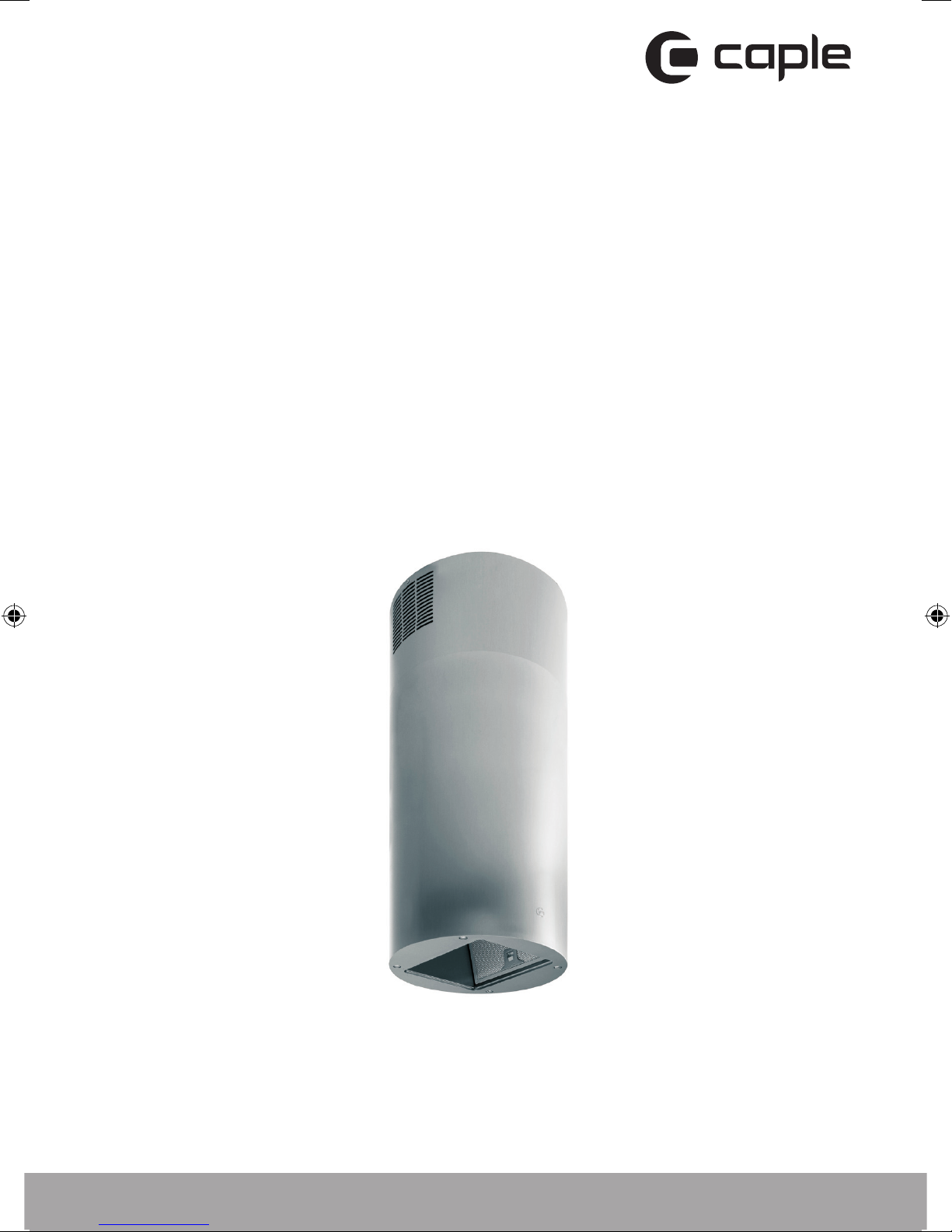
Orbit island extractor
instruction manual
OI363
Page 2

Instruction manual Oi363
Please keep this instruction manual for future reference
CONTENTS
WARNINGS 3
ENVIRONMENTAL PROTECTION 6
USES 7
INSTALLATION 8
REMOTE CONTROL 13
OPERATION MODE 14
TIMING 16
MAINTENANCE 17
2
Page 3

Instruction manual Oi363
Please keep this instruction manual for future reference
WARNINGS
- The appliance is not intended for use by young children
or infirm persons without supervision. Young children
should be supervised to ensure they do not play with the
appliance.
- The cooking surface and the inferior part of the cooker
hood must be at a minimum distance of 65 cm.
- The extracted air can’t be conveyed through or into
a duct used to let out fumes from appliances fed by
energy other than electric power (eg. centralized heating,
radiators, water-heaters, etc.).
- To evacuate the air outlet, please comply with the
pertaining rules given by competent authorities.
- Provide the room with an adequate aeration when a
cooker hood and appliances fed by energy other than
electric power (gas, oil, or coal stoves, etc.) are used
simultaneously. The cooker hood, when evacuating the
extracted air, could generate a negative pressure in the
room which can’t exceed the limit of 0.04 mbar, in order
to avoid the suck of exhausts deriving from the heat
source. Therefore the room should be provided with airintakes to allow a constant flow of fresh air.
- When performing the electrical connections on the
appliance, please make sure that the current tap is
provided with earth connection and that voltage values
correspond to those indicated on the rating label placed
inside the appliance itself.
3
Page 4

Instruction manual Oi363
Please keep this instruction manual for future reference
- Before carrying out any cleaning or maintaining
operations, the appliance needs to be removed from the
electric grid. If the appliance is not provided with a nonseparable flexible cable and plug, or with another device
ensuring omnipolar disconnections from the grid, with an
opening distance between the contacts of at least 3 mm,
then such disconnecting devices must be supplied within
the fixed installation.
- If the fixed appliance is endowed with a supply cord and
a plug, the appliance has to be put in a place where the
plug can be reached easily.
- The use of materials which can burst into flames should
be avoided in close proximity of the appliance. When
frying, please pay particular attention to fire risk due to
oil grease. Being highly inflammable, fried oil is especially
dangerous. Do not use uncovered electric grills.In order
to avoid possible fire risk, all instructions for grease-filter
cleaning and for removing eventual grease deposits
should be strictly followed.
- This appliance complies with all relevant local and
national safety requirements. Inappropriate use can,
however, lead to personal injury and damage to property.
- The cooker hood is not intended for outdoor use.
- It must only be used as a domestic appliance to extract
vapours and remove odours from cooking. Any other
usage is not supported by the manufacturer and could
be dangerous.
4
Page 5

Instruction manual Oi363
Please keep this instruction manual for future reference
- Where a recirculation cooker hood is fitted above a gas
hob, please ensure that there is an adequate supply of
fresh air into the room in which it is installed. Please
seek the advice of a qualified gas fitter (e.g. GasSafe in
the UK) if necessary.
- Children under 8 years of age must be kept away from
the cooker hood unless they are constantly supervised.
- Children 8 years and older may only use the cooker hood
- unsupervised if they have been shown how to use it
safely and recognise and understand the consequences
of incorrect operation.
- The electrical safety of this appliance can only be
guaranteed when correctly earthed. It is essential
that this standard safety requirement is met. If in any
doubt please have the electrical installation tested by a
qualified electrician.
- Do not connect the appliance to the mains electricity
supply by a multi-socket unit or an extension lead. These
are a fire hazard and do not guarantee the required
safety of the appliance.
- The cooker hood can get very hot during cooking due to
heat rising from the hob.
- Do not touch the housing or the grease filters until the
cooker hood has cooled down.
5
Page 6
Instruction manual Oi363
Please keep this instruction manual for future reference
ENVIRONMENTAL PROTECTION
Waste electrical products should not be disposed of with household waste. Please
recycle where facilities exist. Check with your Local Authority or retailer for recycling
advice. This appliance is marked according to the European directive 2012/19/EU on
Waste Electrical and Electronic Equipment (WEEE).
By ensuring this product is disposed of correctly, you will help prevent potential
negative consequences for the environment and human health, which could
otherwise be caused by inappropriate waste handling of this product. The symbol
on the product indicates that this product may not be treated as household waste.
Instead it shall be handed over to the applicable collection point for the recycling of
electrical and electronic equipment. Disposal must be carried out in accordance with
local environmental regulations for waste disposal.
For more detailed information about treatment, recovery and recycling of this
product, please contact your local council, your household waste disposal service or
the retailer where you purchased the product
CE DECLARATIONS OF CONFORMITY
Radio Equipment Directive (RED) 2014/53/EU
This Declaration is issued under the sole responsibility of the manufacturer.
Hereby, Caple declares that the radio equipment included in the product is in
compliance with the RED directive 2014/53/EU.
The full text of the EU Declaration of Conformity is available on our website
www.caple.co.uk.
6
Page 7

Instruction manual Oi363
Please keep this instruction manual for future reference
USES
The appliance is already arranged both for re-circulation and vented installation/
performance.
- In Recirculation mode (Fig.1), the air and fumes conveyed by the appliance are
cleaned both by a grease filter and by an active charcoal filter, and put again into
circulation through the side grids of the chimney. For this version an air deflector is
placed on the superior part of the pipe allowing air recycling as necessary (Fig.1A).
- In Vented mode (Fig.2), fumes are directly conveyed outside, through an
evacuation duct connected with the superior part of the wall or the ceiling. Both
charcoal filter and air deflector are not necessary in this case.
7
Page 8

Instruction manual Oi363
Please keep this instruction manual for future reference
INSTALLATION
Before installing the appliance, make sure that none of the parts are damaged in
any way. In case of damaged parts, contact your retailer and do not proceed with
installation.
Read all of the following instructions with care before installing the appliance.
- Use an air outlet pipe of the shortest possible length.
- Limit the number of pipe bends.
- Use a material approved by standards and regulations.
- Avoid any sudden changes in pipe section (recommended constant diameter: 150
mm or equal surface area).
NOTE: For more information on venting, please see our ‘Extraction & Ventilation
guide’ available on our website www.caple.co.uk.
Attention: at least two people are needed to perform the installation.
Before installing the appliance, in order not to damage the appliance itself, the
metal grease filter should be removed. Such filter can be removed by pushing
the special filter handle toward the back side of the cooker hood and turning it
downwards so to unfasten it from its slot (Fig. 3 A).
Before fixing the hood, place the electric feeding properly into the ornamental pipe
and place a hole for air evacuation in case of a vented mode installation.
Ventilation mode
Place the upper plate (Fig.5.1) on the ceiling. Drill 4 holes, 8 mm each, just next to
the slots. Insert the plastic dowels into the holes (Fig.5.1-A) and screw up the plate
on the ceiling (Fig. 5.1-B). Then fasten the lower structure (Fig. 7.2) on the hood by
making its holes and the metric-thread screws welded on the fan support coincide
(Fig. 7.1). Insert the washers and nuts provided (Fig. 7.2-A) and screw with an
appropriate tool.
Connect the drainpipe to the power unit nozzle and fix securely with a hose clamp.
Insert the upper structure (Fig. 7.3) into the lowest one and adjust its height as
required by matching it with the cooking top’s minimum height. Tighten the two
structures securely with the screws provided (Fig. 7.3). Insert the two extension
8
Page 9

Instruction manual Oi363
Please keep this instruction manual for future reference
tubes (Fig. 7.4 & Fig. 7.5) from above the two structures by making them come
down to the appropriate hoodseat. Lift the hood together with the structure and
the extension tubes to make the four springs (Fig. 7.6) hook to the slots (Fig.
7.3-C). Then tighten the two elements securely (Fig. 6.1 & Fig. 6.2) with the safety
screws (Fig. 6.2-A) and connect the hood tube to the drain hole. Make the electrical
connections. (For versions with display only) Lift the lower pipe until the cable
strap coming out of the extraction unit is uncovered and connect it to the display
cable strap. Put down the lower pipe while paying attention it is being properly
introduced into the hood.
Lift the upper tube (Fig. 7.5) up to the ceiling and insert the two self-tapping screws
(Fig. 7.5-D).
Recirculation mode
Place the upper plate (Fig.5.1) on the ceiling. Drill 4 holes, 8 mm each, just next to
the slots. Insert the plastic dowels into the holes (Fig.5.1- A). Fix the baffle (Fig. 5.2)
to the upper bracket (Fig.5.3) with the four self tapping screws provided (Fig. 5.3
A). Screw up the plate together with the baffle (Fig.5.1 B). Then fasten the lower
structure (Fig. 7.2) on the hood by making its holes and the metric thread screws
welded on the fan support coincide (Fig. 7.1). Insert the washers and nuts provided
(Fig. 7.2-A) and screw with an appropriate tool. Connect the drainpipe to the power
unit nozzle and fix securely with a hose clamp. Insert the upper structure (Fig. 7.3)
into the lowest one and adjust its height as required by matching it with the cooking
top’s minimum height. Tighten the two structures securely with the screws provided
(Fig. 7.3-B). Insert the two extension tubes (Fig. 7.4 & Fig. 7.5) from above the two
structures by making them come down to the appropriate hood seat. Lift the hood
together with the structure and the extension tubes to make the four springs (Fig.
7.6) hook to the slots (Fig. 7.3-C). Then tighten the two elements securely (Fig. 6.1 &
Fig. 6.2) with the safety screws (Fig. 6.2-A) and connect the hood tube to the baffle’s
lower hole. Make the electrical connections. (For versions with display only) Lift the
lower pipe until the cable strap coming out of the extraction unit is uncovered and
connect it to the display cable strap. Put down the lower pipe while paying attention
it is being properly introduced into the hood. Lift the upper tube (Fig. 7.5) up to the
ceiling and insert the two self-tapping screws (Fig. 7.5-D).
WARNING:
Before connecting the flexible exhausting pipe to the motor, make sure the stop
valve, which is on the air outlet of the motor, can swing.
9
Page 10

Instruction manual Oi363
Please keep this instruction manual for future reference
1
3
2
10
B
A
A
B
4
Page 11

Instruction manual Oi363
Please keep this instruction manual for future reference
5
6
7
11
Page 12

Instruction manual Oi363
Please keep this instruction manual for future reference
17
13
14
15
Z
8
9
10
12
Z
B
11
Page 13

Instruction manual Oi363
Please keep this instruction manual for future reference
REMOTE CONTROL
Remote control used for the remote operation of Caple island hoods:
Technical Data
Alkaline battery powered : 12 V mod. 23 A
Operating frequency : 433.92 Mhz
Combinations : 32.768
Max. consumption : 25 mA
Operating temperature: -20 ÷ + 55 °C
Dimensions : 120 x 45 x 15 mm
OPERATING DESCRIPTION
The transmitter is equipped with 5 buttons for cooker hood management, as
specified below:
Light ON/OFF command.
Motor ON (speed level 1) / OFF command.
Reduce speed.
Increase speed.
10-minute timer.
Initial Operating Condition
The manufacturer supplies the radio control
unit ready to be used with codes preset in
the Factory
13
Page 14

Instruction manual Oi363
Please keep this instruction manual for future reference
OPERATION MODE
Standard configuration:
Standard configuration requires all “cooker hoods radio control system” to be
provided with the same transmission code. In the event two cooker hoods radio
control system are installed in the same room or nearby, each system may affect the
operation of the another. Therefore, the code of one radio control system must be
changed.
Generating a new transmission code:
The radio control system is provided with preset codes. Should new codes be
required, proceed as follows: Press simultaneously buttons:
for two seconds. When Leds light on, press buttons:
(within 5 seconds). Leds flashing 3 times indicate the procedure is completed.
WARNING:
This operation deletes permanently the preset codes.
Learning the new transmission code:
Once the transmission code is changed in the radio control unit, the electronic
central unit of the cooker hood must be made to set the new code in the following
way:
Press the main power-off button of the hood and then restore power to the
electronic control unit. Within the next 15 seconds, press the Light Button
to synchronise the central unit with the code.
14
Page 15

Instruction manual Oi363
Please keep this instruction manual for future reference
Reset of the Factory configuration:
To restore the Factory configuration, follow the procedure described below: press
simultaneously buttons
for 2 seconds. When Leds light on, press buttons
(within 5 seconds). Leds flashing 6 times indicate the procedure is completed.
WARNING:
This operation deletes permanently the preset codes.
Emergency button:
In the event that the radio control does not work, use the emergency button to
switch the appliance off.
After any necessary repairs have been performed, reset the emergency button.
WARNING:
The battery should be replaced every year to guarantee the optimal range of the
transmitter. To replace the exhausted battery, take the plastic lid off, remove the
battery and replace it with a new one, observing the correct battery polarities. Used
batteries should be discarded in special collection bins.
WARNING:
Any adjustments or modifications which have not been expressly approved by the
holder of the legal conformity certificate may invalidate the user’s rights relating to
the operation of the device.
The products are endowed with an electronic device which allows the automatic
switching off after 4 hours working from the last operation.
15
Page 16

Instruction manual Oi363
Please keep this instruction manual for future reference
TIMING
- As a result of the new EU65 “Energy label” and EU66 “ Ecodesign” regulations
issued by the European Commission, which came into force as from January 1st,
2015 , our products have been adapted to comply with these new requirements.
All of the models complying with the energy label requirements, are equipped
with new electronics including a timer device for speed controls, when the air
capacity exceeds 650m³/h.Internal motor models, with maximum air capacity
higher than 650m³/h, are equipped with a timer device that automatically switches
the speed from 4th to 3rd speed, after 5 minutes operation.
- External motor models are equipped with remote motors that , as for internal
motor versions, include a timer device that switches down the speed when it
exceeds 650 m³/h. (See External Motors Instructions). Remote motors, whose air
capacity exceeds 650m³/h at both 4th and 3rd speed, will have the following by
default timer control functions: The speed is automatically switched from 4th to
2nd speed, after 6 minutes operation.
- If the appliance is working at 3rd speed, it is automatically switched to 2nd
speed, after 7 minutes operation. Operation speeds can also be changed during
operation.The energy consumption of the appliance in standby mode is lower than
0.5W.
16
Page 17

Instruction manual Oi363
Please keep this instruction manual for future reference
MAINTENANCE
- An accurate maintenance guarantees good functioning and long lasting
performance.
- Particular care is due to the grease filter panel. It can be removed by pushing its
special handle toward the back-side of the cooker hood and turning the filter
downwards so to unfasten it from its slot (Fig.3A). To insert the filter just perform
the opposite operation.
- In case the appliance is used in recirculating mode, the active charcoal filter
(Fig.8Z) needs to be periodically replaced. The charcoal filter can be removed by
removing the grease filter first (Fig.3A), and by pulling its special plastic tongue
until it is unfastened from its slot. Reinsert the charcoal filter by operating in
the opposite way. The charcoal filter should be replaced after every 6 months.
however this can depend on its use. replacement filters can be purchased via our
Caple website www.caple.co.uk
- To clean the appliance itself tepid water and neutral detergent are recommended,
while abrasive products should be avoided. For steel appliances specialized
detergents are recommended (please follow the instructions indicated on the
product itself to obtain the desired results).
- Before replacing the lamps, disconnect the appliance from the electric mains.
Remove the grease filter and the carbon filter, if it is inserted. Once the burnt out
bulb is localized, turn it anticlockwisely and replace it with a bulb of the same
type. To replace and remove the led lamp (Fig.9) remove the lamp by inserting a
screwdriver or another sharp tool between the lamp and its chromed support and
replace it with a lamp of the same kind.
- If the supply cord is damaged, it must be replaced by the manufacturer or its
service agent or a similarly qualified person in order to avoid a hazard.
17
Page 18

Instruction manual Oi363
Please keep this instruction manual for future reference
Notes:
18
Page 19

Instruction manual Oi363
Please keep this instruction manual for future reference
Notes:
19
Page 20

Contact Caple on 0117 938 7420 or for spare parts www.caple.co.uk
Caple Service
Fourth Way
Avonmouth
Bristol
BS11 8DW
t: 0117 938 7420
e: service@caple.co.uk
www.caple.co.uk
 Loading...