

Page 1
Contact Caple on 0117 938 7420 or for spare parts www.caple.co.uk
Downdraft induction hob
instruction manual
DD935BK
Page 2

Instruction manual DD935BK
Please keep this instruction manual for future reference
CONTENTS
WARNINGS 3
SAFETY WARNINGS 3
ENVIRONMENTAL PROTECTION 7
INSTALLATION INSTRUCTIONS 8
POSITIONING 8
VENTILATION 8
INSTALLATION 10
ELECTRICAL CONNECTIONS 12
COOKWARE 16
HOB INSTRUCTIONS 17
DOWNDRAFT INSTRUCTIONS 23
CLEANING AND MAINTENANCE 25
TROUBLESHOOTING 26
2
Page 3

Instruction manual DD935BK
Please keep this instruction manual for future reference
WARNINGS
- Keep these instructions for use with the appliance. If the
appliance should be sold or passed on to others, make
sure that the instructions are passed on with it. We
thank you for taking note of these suggestions before
installing and using the appliance. They have been
written for your personal safety and the safety of others.
- This appliance is not intended for use by persons
(including children) with reduced physical, sensory or
mental capabilities, or lack of experience and knowledge,
unless they have been given supervision or instruction
concerning use of the appliance by a person responsible
for their safety.
SAFETY WARNINGS
- Use the appliance only in household situations for the
preparation and warming of food. All other types of use
are not permitted.
- Children under 8 years of age must be kept away from
the appliance unless they are under constant supervision.
- Children 8 years and older must only be allowed to use
the appliance if they have been given supervision or
instruction concerning use of the appliance in a safe way
and understand the hazards involved.
- Children shall not play with the appliance.
3
Page 4

Instruction manual DD935BK
Please keep this instruction manual for future reference
- Cleaning and user maintenance shall not be made by
children without supervision.
- Installation, repair and maintenance work should only be
performed by an authorised service technician. Work by
unqualified persons could be dangerous for the user.
RISK OF ELECTRIC SHOCK!
- If the appliance is defective or chipped, cracked or
broken in any way, immediately switch it off and do not
continue to use it. Disconnect it from the electrical power
supply.
WARNING
- If the supply cord of the appliance is damaged, it must
be replaced by the manufacturer, its service agent or
similarly qualified persons in order to avoid a hazard
- The appliance and its accessible parts become hot during
use. Care should be taken to avoid touching heating
elements.
- Unattended cooking on a hob with fat or oil can be
dangerous and may result in fire. NEVER try to extinguish
a fire with water, but switch off the appliance and then
cover flame e.g. with a lid or a fire blanket.
- The hob is hot during use and remains so for some time
after being switched off. The risk of burns remains until
the residual heat indicators have gone out.
4
Page 5

Instruction manual DD935BK
Please keep this instruction manual for future reference
CAUTION
- The cooking process has to be supervised. A short term
cooking process has to be supervised continuously.
DANGER OF FIRE
- Do not store items on the cooking surfaces! Metallic
objects such as knives, forks, spoons and lids should not
be placed on the hob surface since they can become hot.
- Always switch the cooking zones off after use!
- The appliance is not intended to be operated by means
of an external timer or separate remote-control system.
SAFETY INSTRUCTIONS
- When the appliance is delivered, check the overall
appearance of the packaging. Any remarks should be
written on the delivery note, of which you keep a copy
- Your appliance is designed for normal domestic use. It
is not designed for commercial or industrial use, or for
purposes other than those for which it was designed.
- Any consequences of or damage from incorrect
installation or incorrect use of the appliance will not be
covered by the manufacturer’s guarantee.
- Do not ever change or try to change the characteristics
of this appliance. This would be a danger. Repairs must
be performed only by an authorised technician. Always
5
Page 6

Instruction manual DD935BK
Please keep this instruction manual for future reference
disconnect the hood before carrying out cleaning or
maintenance operations.
- Adequately ventilate the room when a extractor
and other appliances, powered by energy other than
electricity, are used simultaneously, so that the extractor
does not suck any combustion fumes
- Never use steam or high-pressure devices for cleaning
your appliance (regulations regarding electrical safety).
- Never use the extractor without the grease filters
6
Page 7
Instruction manual DD935BK
Please keep this instruction manual for future reference
ENVIRONMENTAL PROTECTION
Waste electrical products should not be disposed of with household waste. Please
recycle where facilities exist. Check with your Local Authority or retailer for recycling
advice. This appliance is marked according to the European directive on Waste
Electrical and Electronic Equipment (WEEE).
By ensuring this product is disposed of correctly, you will help prevent potential
negative consequences for the environment and human health, which could
otherwise be caused by inappropriate waste handling of this product. The symbol
on the product indicates that this product may not be treated as household waste.
Instead it shall be handed over to the applicable collection point for the recycling of
electrical and electronic equipment. Disposal must be carried out in accordance with
local environmental regulations for waste disposal.
For more detailed information about treatment, recovery and recycling of this
product, please contact your local council, your household waste disposal service or
the retailer where you purchased the product
CE DECLARATIONS OF CONFORMITY
This appliance has been manufactured to the strictest standards and complies
with all applicable legislation, Low Voltage Directive (LVD) and Electromagnetic
Compatibility (EMC).
7
Page 8

Instruction manual DD935BK
Please keep this instruction manual for future reference
INSTALLATION INSTRUCTIONS
These instructions are for qualified personnel and are a guide for the installation
process, regulations and maintenance in accordance with the law and current
standards.
Before securing the hob to the worktop, ensure the downdraft has been assembled
as per the ‘Downdraft Assembly’ instructions on page 10.
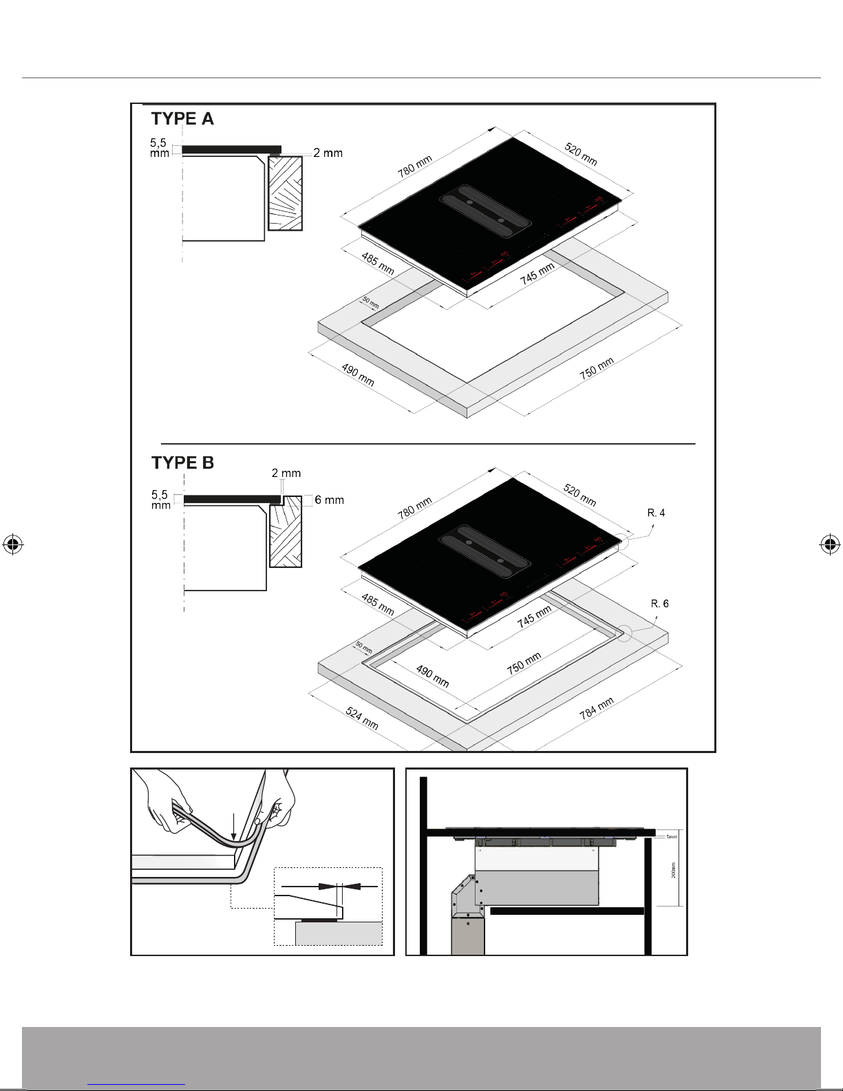
POSITIONING
The hob is designed for either an inset or flush mounted installation, the way it is
illustrated in Fig.1. Apply the sealing strip (Fig.2) along the whole perimeter (for
dimensions of the cut out see Fig.1). Fix the hob into place with 4 fixing brackets,
keeping in mind the depth of the work surface (Fig.4).
If the lower part of the appliance is accessible after installation via the unit it is
installed in, it is necessary to mount a separating panel as shown in Fig. 4, keeping
in mind the distances stated.
VENTILATION
To ensure adequate ventilation, a 5mm gap below the worktop on the front edge
(see fig.3), should be applied.
If the product is being recirculated, a 5mm ventilation slot will also need to
be included in the kitchen plinth around the entire perimeter of the island.
Alternatively a vent grill can be installed onto the plinth in line with where the
motor has been installed to allow the clean air to escape back into the room.
8
Page 9
Instruction manual DD935BK
Please keep this instruction manual for future reference
min. 50 mm
50
mm
20 mm
3
- INSET
- FLUSH MOUNTED
Fig.1
~ 2 mm
Fig.2
Fig.3
9
Page 10

Instruction manual DD935BK
A
B
A
4
Fig.4
A
B
min 10 max 30 mm
B
min 30 max 50 mm
DOWNDRAFT ASSEMBLY
1. Before carrying out the downdraft installation, please check that all components
are not damaged, in such a case contact your retailer and do not carry out any
installation operation.
- Use solid 150mm ducting whose maximum length does not exceed 5 meters
- Limit the number of elbows in the ducting, since each elbow reduces the air
capacity of 1 linear meter. (E.g. if you use no. 2 x 90° elbows, the length of
ducting should not exceed 3 meters).
- Avoid abrupt direction changes.
- Use a 150mm constant diameter or a similar section ducting for the whole length.
- Use ducting approved by relevant standards in force. The manufacturer shall
not be held liable for air capacity or noise problems due to non-observance of
aforementioned instructions and no warranty will be provided in such a case.
10
Page 11

Instruction manual DD935BK
2. Place the upturned hob on a suitable surface, making sure the glass is protected
from scratches.
Take the ‘filtering chamber ‘out of the packaging and install it as shown in fig. 5.
The ‘filtering chamber’ metal hooks shall be inserted in their suitable slots found
on the hob rear side, as shown in fig. 6.
After fitting the ‘filtering chamber’ to the hob,fasten it using the metric screw
provided with the appliance, which shall be installed as shown in fig. 7.
3. Fit the hob into the cabinet, as shown on page 8-10.
Take the motor unit out of the packaging, fix the metal joint on it using the screws
provided with the appliance, as shown in fig. 8.
After installing the hob, place the motor unit immediately under the hob, as
shown in fig. 9.
In order to install the motor unit in such a way as it can touch the floor , make a
410mm X 410mm opening in the cabinet floor (see fig.17).
Then place the two metal telescopic conduits into the motor unit air inlet (figure
10), and fix them using the screws supplied with appliance.
Lift the internal metal conduit until it reaches the ‘filtering chamber’ and fix it using
the screws supplied with appliance (fig.11).
Seal the air flow opening with the adhesive tape provided with the appliance, as
shown in figure 12.
Connect the ducting to the motor unit. You can use the air outlet on the right
or left side of the motor unit, according to the needs of the kitchen: remove the
four screws fixing the outlet flange and replace it with the metal lid placed on the
opposite side.
The air outlet which is not going to be used must always be covered and closed
with the metal lid.
Another two plastic flanges are provided with the appliance to connect different
section ducts.
Flanges provided have the following sections:
230x80 mm
220x90mm
218x55mm (recommended for recirculating mode installation only).
11
Page 12

Instruction manual DD935BK
Fit the two grease filters into their housing, by passing them through the hob
central opening, see fig. 13.
Fit the metal grid in order to close the hob central opening, as shown in fig. 14.
Place the wiring box near the appliance, in order to connect the flat cable to the
corresponding flat cable of the touch - control panel.
Connect the motor unit cable to the terminal block found inside the plastic black
box, see fig. 15B.
5
7
6
8
12
Page 13

Instruction manual DD935BK
9
10
11
13
12
14
13
Page 14

Instruction manual DD935BK
A
B
A
B
A
B
min 10 max 30 mm
min 30 max 50 mm
15
17
16
14
brown
L1
2 x 220-240 V~
220-240 V~
3x1,5mm
blue earth
N
Fig.18
2
Page 15

Instruction manual DD935BK
Please keep this instruction manual for future reference
ELECTRICAL CONNECTIONS (FIG.18)
Before making the electrical connections, check that:
- The system ratings meet the ratings indicated on the identification plate fixed on
the lower part of the worktop;
- The fuse rating for this appliance is 40amp.
- The system is fitted with efficient ground wires in accordance with the laws and
current standards.
Grounding is mandatory by law. If the domestic appliance is not supplied with a
cable, use material suitable for the absorption value indicated on the identification
plate and the operating temperature. An omnipolar switch must be installed with
a minimum 3 mm opening between the contacts and appropriate for the load
indicated on the plate and in accordance with current standards (the yellow/green
ground conductor must not be disconnected by a switch). When the appliance has
been installed, the omnipolar switch must be easily accessible.
WARNING
Place the metal box containing the electronic components at a distance of no less
than 65 cm from the suctioning surface of the cooker hood.
Connecting the product to the mains electricity must be carried out by technically
qualified personnel. The product must be connected to an electrical system correctly
designed and installed. The electrical system must comply with VDE0100 standard.
NOTE
We recommend installing the metal box containing the electronic components at
least 10 cm above floor level and at a suitable distance from all heat sources (e.g.
oven sides or hob).
CAUTION
This appliance is fitted with an H05 VVF 3 conductor, 0.75 mm2 (neutral, phase,
and ground) power cord. This can be connected up to a 220 - 240 V mono-phase
electrical network through a CEI 60083 approved power socket, which must remain
accessible after installation, in compliance with installation regulations. We decline
any responsibility in case of accidents caused by a lack of ground connection or
incorrect ground connection. The appliance must be fed through a differential
protection device (RCD), with a nominal residual current not exceeding 30mA. If the
power cord is damaged, call the after-sales service to avoid any risk.
15
Page 16

Instruction manual DD935BK
Please keep this instruction manual for future reference
COOKWARE
Induction
A
B
The use of appropriate cookware is an essential factor for induction cooking. Check
that your pots are suitable for the induction system. Only ferromagnetic cookware
made of the following materials is suitable for induction hobs:
- Enameled steel
- Cast iron
- Induction-capable stainless steel cookware.
To determine whether the cookware is suitable, check whether the base of the
pot or pan attracts a magnet. There are other induction-capable pots and pans
whose bases are not completely ferromagnetic. To get good cooking results, we
recommend that the dimension of the ferromagnetic area of the cookware match
the size of the burner. We advise cookware having a flat base (Fig.6A). This way you
can use the power optimally.
Do not use cookware with a rough base to avoid scratching the surface of the hob.
A very important factor in induction cooking is the dimension of the pot compared
to the plate used. The cooking zones allow the use of cookware with bases of
various diameters. It is, however, preferable to use the appropriate cooking zone for
the dimension of the pot.
16
Page 17

Instruction manual DD935BK
Please keep this instruction manual for future reference
HOB INSTRUCTIONS
G
D
H
B A C
F
I
E
D
F
E
min
Induction
A
B
The appliance is operated using the control panel sensor keys. Functions are
controlled by touching the sensor keys and confirmed by displays and acoustic
signals. Touch the sensor keys from above, without covering other sensor keys.
TOUCH CONTROLS
A. On/Off key
B. Lock key
C. Pause key
D. Cooking Zone Power Slidebar
E. Programs key
F. Cooking zone Display
G. Timer [+] key
H. Timer [-] key
I. Timer display
FAN
A. On/Off key
B. Fan speed slidebar
C. Fan speed display
D. Timer Key
17
Page 18

Instruction manual DD935BK
Please keep this instruction manual for future reference
SWITCHING THE APPLIANCE ON
G
D
H
B A C
F
I
E
D
F
E
min
7
Induction
A
B
6
Press the On-Off key to switch the hob on. All the displays relative to the cooking
zones switch on in the «0» standby position. The control unit remains active for 10
seconds. If no cooking zone is selected within this time, the appliance switches off
automatically.
SWITCHING A COOKING ZONE ON
Select the desired cooking zone and press or slide on the corresponding slidebar
(D). The power of the single cooking zone can be adjusted in 9 different positions
and will be shown on the relative luminous display with a level from “1” to “9”.
Slide right on the slidebar to increase the power level, slide left to decrease it.
BRIDGE ZONES -
This function allows you to combine the front cooking zone to the rear cooking
zone to create one large zone (zone 1+2 and 3+4, Fig. 8).
Pay attention in placing the
8
( A) Max. 3700 W 16A
( B) Max. 3700 W 16A
cookware in the correct position
on the cooking zones. To
activate the Bridge function press
simultaneously on both Sliderbars
Octa 220x184
Max.
2100 W
P: 3700 W
Octa 220x184
Max.
2100 W
P: 3700 W
of the two adjacent cooking zones.
The bridge luminous symbol
- will appear on the side of
the two cooking zones display
indicating that the function is
active. Now it is possible to set the
heat level of the bridge zone.
NOTE: the settings of the bridge zone are only enabled by the front cooking zone
Octa 220x184
Max.
2100 W
P: 3700 W
Octa 220x184
Max.
2100 W
P: 3700 W
slidebar and sensor keys. To disable the Bridge function press simultaneously on
both Sliderbars of the two adjacent cooking zones. The bridge illuminated symbol
- turns off.
18
Page 19

Instruction manual DD935BK
Please keep this instruction manual for future reference
POT DETECTION
Each induction cooking zone has a pot detection minimum limit, which varies
according to the material of the cookware being used. For this reason, you should
choose the cooking zone which is most suitable for the diameter of the cookware
you are going to use.
If the symbol appears on the cooking zone display, it means that:
- The cookware used is not suitable for induction cooking.
- The cookware diameter is smaller than the one allowed by the hob.
- No cookware is on the cooking zone.
RESIDUAL HEAT H
If the temperature of the cooking zone is still high (over 50°C) after it has been
switched off, the relative display will indicate the symbol H (residual heat).
The symbol will stay on even when the appliance is switched off and will only
switch off when the burn risk in no longer present.
POWER BOOST (QUICK HEATING) P
This program further reduces the cooking time of a certain cooking zone, by
bringing the temperature to the maximum heat level for 10 minutes.
At the end of this timeframe, the cooking zone heat level will automatically go back
to level 9. The use of this function is recommended for heating large quantities of
liquids (e.g. water to cook pasta) or food in a very short time.
To activate this program slide to the far right on the slidebar until the P symbol
appears on the cooking zone display.
AUTOMATIC WARM-UP R
All cooking zones are equipped with an “automatic warm up” function. This
feature sets the cooking zone to the highest heat level for a certain period of time
and then automatically switches back to the cooking setting that was originally set.
The length of time that the automatic warm up function operates depends on the
heat setting selected. To activate the “automatic warm up” function on a cooking
zone place your finger on the slidebar at the desired heat level an hold the position
for 3 seconds until the symbol R, alternating with the selected heat level, appears
on the cooking area display.
19
Page 20

Instruction manual DD935BK
Please keep this instruction manual for future reference
SPECIAL PROGRAMS
The cooktop has three special programs that have already been set to perform
special cooking operations.
Bake
The ‘‘Bake’’ program sets the heat temperature of the selected cooking zone
at 42°C to melt chocolate, butter or the like. To activate this program press the
Programs key once. The Bake LED lights up besides the cooking zone
display.
Keep Warm
The ‘‘Keep Warm’’ program sets the heat temperature of the selected cooking
zone at 70°C to keep food warm. To activate this program press the Programs key
twice. The Keep Warm LED lights up besides the cooking zone display.
Boil Control
The ‘‘Boil Control’’ program sets the heat temperature of the selected cooking
zone at 94°C to bring to a boil slowly preparing sauces or soups and stews. To
activate this program press the Programs key three times, the Boil Control LED
lights up besides the cooking zone display.
TIMER
This function allows you to set the time from 1 minute to 1 hour and 59 minutes
for the automatic switch off of a cooking zone.
Timer Display
From 1 minute to 9 1.00 , 2.00 ... 9.00
From 10 minutes to 59 0.10, 0.15 ... 0.59
From 1 hour to 1hr 59minutes 1.00, 1.10 ... 1.59
Switch on a cooking zone by sliding on the slidebar to adjust the heat level. To
activate the timer press simultaneously the “+“ and “-“ keys on the timer area until
the clock symbol lights up beside the cooking zone display, then set the desired
time using the timer “+“ and “-“ keys within 5 seconds. Wait for 5 seconds for the
automatic confirmation. The time countdown will start on the timer display.
20
Page 21

Instruction manual DD935BK
Please keep this instruction manual for future reference
When time elapses the cooking zone will automatically switch off, the timer display
will show a flashing “000” and an acoustic signal will be heard. Press the “+“ or
“-“ key on the timer area to stop the signals. To disable the timer of a cooking
zone press repeatedly and simultaneously the “+“ and “-“ keys on the timer area
until the clock symbol lights up beside the display of the desired cooking zone,
press again the timer “+“ and “-“ keys simultaneously, then bring the timer value
back to “000” by using the timer “-“ key. Wait for 5 seconds for the automatic
confirmation. The clock symbol beside the cooking zone display goes off.
EGG TIMER/REMINDER
When no cooking zone is active it is possible to set an acoustic reminder which
stays active after switching the appliance off. When the Egg timer/Reminder
function is active, the Timer function cannot be selected.
To enable this function press simultaneously the timer “+“ and “-“ keys. The clock
symbol lights up below the timer display. Set the time, ranging from 1 minute to 1
hour and 59 minutes, by pressing the “+“ and “-“ keys. Wait for 5 seconds for the
automatic confirmation. The time countdown will be shown on the timer display.
When time elapses the display will show a flashing “000” and an acoustic signal will
be heard. Press the “+“ and “-“ key on the timer area to stop the signals.
To disable the Egg timer/Reminder function press simultaneously the timer “+“
and “-“ keys. The clock symbol lights up below the timer display. Bring the timer
value back to “000” by using the “-“ key. Wait for 5 seconds for the automatic
confirmation. The clock symbol beside the timer display goes off.
PAUSE
II
When at least one cooking zone is operating it is possible to momentarily pause
the appliance switching off the cooking zones. To enable this function press the
Pause key. The relative led lights up and all the cooking zone displays show the
symbol “
II
“. Previously programmed timers will be stopped. The pause can last for
maximum 10 minutes. If this status is not terminated within this time the appliance
switches off. To disable the Pause function press the Pause key and slide right on
the flashing slidebar within 10 seconds.
RECALL
When the appliance has been switched off by mistake it is possible to quickly recall
the previously active settings by pressing the On - Off key within 5 seconds, then
pressing the Pause key within another 5 seconds. If the recall function is available
the relative led will be flashing when the appliance is switched on again.
21
Page 22

Instruction manual DD935BK
Please keep this instruction manual for future reference
CONTROL LOCK
Controls can be locked in order to prevent any risk of unintentional changes to the
settings (children, cleaning operations, etc.). To activate this function press the Lock
key. The relative led will light up. The function remains active when the appliance
is switched off and on again. To disable the Control Lock function simply press the
Lock key. The relative led will go off.
CHILD SAFETY LOCK “L”
This function serves the purpose of preventing children from switching on the
appliance even accidentally or intentionally. The Child safety lock can only be
activated within 10 seconds from the switching on of the appliance, with all the
cooking zones off. To activate this function press simoultaneously the Lock key and
the Pause key, then again the Control Lock key. The symbol “L” will appear on all
displays to confirm your selection and the relative led will light up. When the Child
safety lock is enabled you can switch the appliance off. The Child safety lock is still
enabled when the appliance is switched on again.
To unlock the appliance permanently, press simoultaneously the Lock key and
the Pause key, then again the Pause key. In this case the Child safety lock won’t
be enabled when the appliance is switched on again.
To unlock the appliance temporarily press simoultaneously the Lock key and
the Pause key. In this case the Child safety lock will still be active each time the
appliance is switched on again.
SWITCHING A COOKING ZONE OFF
To switch a cooking zone off bring its level back to “0” by sliding left on the
corresponding slidebar.
SWITCHING THE APPLIANCE OFF
To turn off the hob entirely hold down the On - Off key.
SAFETY SWITCH
The appliance has a safety switch that automatically switches off the cooking zones
when they have been operating for a certain amount of time at a given power level.
22
Page 23

Instruction manual DD935BK
Please keep this instruction manual for future reference
POWER LEVEL OPERATING
TIME
LIMIT (hours)
1-2 6
POWER MANAGEMENT
All cooking zones are connected to one phase. The
phase has a maximum electricity loading of 3700
W/230V (fig. 8).
3-4 5
5 4
The function divides the heat level between
cooking zones and activates when the total
electricity loading of the cooking zones exceeds
6-7-8-9 1.5
3700 W. The function decreases the heat level to
the other cooking zones. The heat setting display
of the reduced zones changes between two levels
DOWNDRAFT INSTRUCTIONS
Turning the Fan ON/OFF
Press the On - Off key to turn the fan on. This will automatically set at level 2.
To turn off the fan, press the On - Off key.
Increasing/decreasing the fan speed
To increase the speed slide to the right on the slide-bar. To decrease the speed slide
to the left on the slide-bar. The LEDs in the fan speed display will show which speed
the fan is set to.
Timer
Press the Timer key to set a 10 minute timer. The LED on the fan speed display will
flash to show this has been set. once the 10 minutes are up, the fan will turn off
automatically.
Automatic turn off
After 4 hours of continuously working, the appliance turns off automatically.
Grease filters saturation
Press a total of 30 hours of operation, the speed indicators will all flash
simultaneously, signalling the grease filters saturation. Clean the filters either by
hand with warm soapy water, and leave to dry, or clean in the dishwasher. Once
clean and re inserted, reset the function by pressing the “TIMER” key for at least 3
seconds whilst the appliance is switched off.
23
Page 24

Instruction manual DD935BK
Timing
As a result of the EU65 “Energy label” and EU66 “ Ecodesign” regulations issued
by the European Commission, which came into force as from January 1st, 2015 ,
our products have been adapted to comply with these new requirements. All of
the models complying with the energy label requirements, are equipped with new
electronics including a timer device for suction speeds control, when the air capacity
exceeds 650m³/h. Internal motor models, with maximum air capacity higher than
650m³/h, are equipped with a timer device that automatically switches the suction
speed from 4th to 3rd speed, after 6 minutes operation. External motor models
are equipped with remote motors that, as for internal motor versions, include a
timer device that switches down the suction speed when it exceeds 650 m3/h.
(See External Motors Instructions). Remote motors, whose air capacity exceeds
650m³/h at both 4th and 3rd speed, will have the following by default timer control
functions: The suction speed is automatically switched from 4th to 2nd speed, after
6 minutes operation. If the appliance is working at 3rd speed, it is automatically
switched to 2nd speed, after 7 minutes operation. Operation speeds can still be
changed during operation. The energy consumption of the appliance in standby
mode is lower than 0.5W.
24
Page 25

Instruction manual DD935BK
CLEANING AND MAINTENANCE (HOB)
Remove any residues of food and drops of grease from the cooking surface by
using a glass scraper or similar. Clean the heated area as thoroughly as possible
using suitable products, and a cloth/ paper, then rinse with water and dry with a
clean cloth. Using the scraper immediately remove any fragments of aluminium and
plastic material that have unintentionally melted on the heated cooking area, or
residues of sugar or food with a high sugar content. In this way, any damage to the
hob surface can be prevented. Under no circumstances should abrasive sponges, or
corrosive chemical detergents, such as oven sprays or stain removers, be used.
WARNING:
STEAM CLEANERS MUST NOT BE USED.
CLEANING AND MAINTENANCE (DOWNDRAFT)
Careful maintenance ensures proper operation and good performances over time.
Grease filters can be washed by hand or in the dishwasher.
Grease filters shall be cleaned depending on use, at least once every two months.
The charcoal filters shall be replaced depending on use, at least once every six
months.
To buy replacement charcoal filters (CAP76CF), visit www.caple.co.uk.
Use only tepid water and neutral detergents to clean the appliance; the use of
products containing abrasive substances shall be avoided.
25
Page 26

Instruction manual DD935BK
TROUBLESHOOTING
Problem Possible cause Remedy
You cannot activate
or operate the
appliance.
The hob deactivates.
Residual heat
indicator does not
come on.
The appliance is not connected to an
electrical supply or it is connected
incorrectly.
The fuse has released / tripped
It’s been more than 10 seconds from
switching on the appliance.
2 or more keys pressed at the same
time.
Pause function operates.
There is water or fat stains
on the control panel.
You put something on the
sensor key ON-OFF.
The zone is not hot because
it operated only for a short
time.
Check if the appliance is correctly
connected to the electrical supply.
Refer to “Electrical connections” chapter.
Make sure that the fuse is the cause of the
malfunction. If the fuse releases again and
again, contact a qualified electrician.
Activate the appliance again and
set the heat setting in less than 10 seconds.
Touch only one sensor key.
Refer to “Using the hob”
chapter.
Clean the control panel.
Remove the object from the sensor
key.
If the zone operated sufficiently
long to be hot contact an
Authorised Service Centre.
Automatic Warm Up
function does not
operate.
The heat setting
changes between
two levels.
The sensor keys
become hot.
- comes on.
L comes on.
comes on.
The zone is hot.
The highest heat setting is
set.
Power management
function operates.
The cookware is too large
or you put it too near to the
controls.
Safety Switch operates.
The Child Lock function
operates.
Water or cooking utensils
above the control panel.
Let the zone become sufficiently
cool.
The highest heat setting has the
same power as the function.
Refer to “Using the hob”
chapter.
Put large cookware on the rear
zones if possible.
Deactivate the appliance and
activate it again.
Refer to “Using the hob”
4 chapter.
Remove the objects from the
control panel.
26
Page 27

Instruction manual DD935BK
Problem Possible cause Remedy
comes on.
E and a number
come on.
E2 comes on.
E21 comes on.
There is no cookware on
the zone.
The cookware is incorrect.
The dimension of the
bottom of the cookware is
too small for the zone.
The cookware does not
cover the cooking zone.
There is an error in the
appliance.
The induction coils are
overheated.
The appliance is
overheated. The cooling
fan might be blocked.
Put cookware on the zone.
Use the correct cookware. Refer
to “Induction Cooking” chapter.
Use cookware with correct
dimensions. Refer to “Induction
Cooking” chapter.
Cover the cooking zone fully.
Disconnect the appliance from
the electrical supply for some
time. Disconnect the fuse from
the electrical system of the house.
Connect it again. If comes on
again, contact an Authorised
7 Service Centre.
Allow the appliance to cool down.
Allow the appliance to cool down.
Check if objects block the cooling
fan. If comes on again, contact an
Authorised Service Centre.
E31 comes on. Incorrect data configuration.
None or faulty communication
E47 comes on.
U400 comes on.
E22, E20, E36, E5,
E6 or E9 comes on.
between control panel and induction
coils.
Control Panel is wrongly
connected.
An internal component
of the appliance needs
replacing.
New configuration needed.
Contact an Authorised Service Centre.
Ensure that connection cable
is plugged on correctly and
functional.
Connect to correct mains voltage.
Contact Caple service
If you cannot find a solution to the problem yourself, contact Caple service.
Provide the model and serial number from the rating plate.
Telephone : 0117 938 1900
Email : service@caple.co.uk
27
Page 28

Instruction manual DD935BK
Please keep this instruction manual for future reference
Caple Service
Fourth Way
Avonmouth
Bristol
BS11 8DW
t: 0117 938 7420
e: service@caple.co.uk
www.caple.co.uk
V1 - 20112017
28
 Loading...