

Page 1

Instruction Manual
Gas oven
with
electric grill
Model: C 270G/SS
GB
Page 2
2
Thank you for buying your new CAPLE Built-in Oven. To ensure that you get the best
results from your new CAPLE oven, we strongly suggest that you read this instruction manual thoroughly before use. This manual contains installation advice, cleaning
tips and a cooking guide, as well as other important facts about your CAPLE oven. If
treated with care, your CAPLE oven should give you years of trouble-free cooking.
For Spare Parts, Technical Advice
or Product Service call the
CAPLE HELPLINE on 0870 241 1142
(Answerphone outside office hours)
The CEmarking confirms that the appliance conforms to the following EU directives:
- safety requirements of EEC Directive “Gas” 90/396;
- safety requirements of EEC Directive “Low voltage” 73/23;
- protection requirements of EEC Directive “EMC” 89/336;
- requirements of EEC Directive 93/68.
Page 3

3
Safety Reminders
Instruction Book
This appliance should only be used for
it’s intended purpose as described in
these instructions.
Ensure that you fully understand these
instructions before operating this appliance.
Space Requirements
Ensure that the specified ventilation
space around the appliance is not
obstructed.
Food Splashes
Always wipe clean the oven after use.
Food splashes can carry on cooking next
time and may become a fire hazard.
Hot Surfaces
It is important to remember that the surfaces of cooking appliances get hot during use and retain the heat for some time
after switching off.
It is therefore advisable to keep small
children away from the appliance.
The Grill element
Is exposed, so take great care when
placing food in the oven or removing it.
Use gloves.
DO NOT line the oven, grids, trays etc.
with aluminium foil as this could adversely affect the heating elements and it
could also damage the interior surfaces.
DO NOT place flammable materials in
the oven.
Faults
Do not continue to use this appliance if it
appears to be faulty.
After Use
Switch the appliance controls off.
Ensure that the gas oven thermostat
knob is in position ● (off), and close the
main gas delivery valve or the gas
cylinder valve.
Always switch off at the isolating switch
before cleaning the appliance, or
attempting any maintenance task, or
when not in use for long periods (when
on holiday).
CAPLE Service
To ensure the continued safe and efficient operation of this appliance, we recommend that any servicing or repairs are
carried out only by an authorised CAPLE
SERVICE ENGINEER.
Page 4

4
Electrical Requirements
WARNING!
ELECTRICITY CAN BE EXTREMELY DANGEROUS.
THIS APPLIANCE MUST BE EARTHED.
For your safety please read the following information:
• This appliance must be installed by a qualified technician according with the current
local regulations and in compliance with the manufacturer instructions.
• The appliance must be connected to the electrical network verifying above all that the
voltage corresponds to the value indicated on the specifications plate and that the
cables section of the electrical plant can bear the load which is also indicated on the
plate.
• The appliance is supplied without a power supply plug and therefore if you are not
connecting directly to the mains, a standardized plug suitable for the load must be
fitted.
• A properly earthed three pin plug (fused at 13 amps, to BS 1362 ASTA approved) must
be used. As the colours of the wires in the mains lead of this appliance may not
correspond with the coloured markings identifying the terminals in your plug, proceed
as follows.
The wire which is coloured GREEN & YELLOW must be connected to the terminal in
the plug which is marked with letter "E" or by the Earth symbol or coloured GREEN &
YELLOW.
The wire which is coloured BLUE must be connected to the terminal which is marked
with the letter "N" or coloured BLACK.
The wire which is coloured BROWN must be connected to the terminal which is marked
with the letter "L" or coloured RED.
IF THE MOULDED MAINS PLUG IS UNSUITABLE FOR THE SOCKET OUTLET IN
YOUR HOME OR IS REMOVED FOR ANY OTHER REASON, THEN THE FUSE
SHOULD BE REMOVED AND THE CUT OFF PLUG DISPOSED OF SAFELY TO
PREVENT THE HAZARD OF ELECTRIC SHOCK.
THERE IS A DANGER OF ELECTRICAL SHOCK IF THE CUT OFF PLUG IS
INSERTED INTO ANY 13 AMP SOCKET OUTLET.
Page 5
5
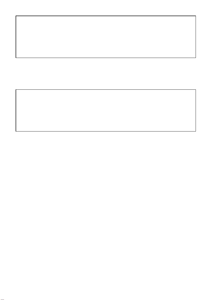
1 - Electrical Installation - Wall box connection
This appliance must be connected to a
double pole isolating switch (fig. 1.1) and
to the terminal block in the cooker (figs.
1.2 & 1.3) using the following guide:
FUSE
DOUBLE POLE SWITCHED
FUSED SPUR OUTLET
USE A 13 AMP FUSE
ON
Fig. 1.1
1) The wire which is coloured brown
must be connected to the terminal
marked L (Live), or coloured Red.
2) The wire which is coloured blue must
be connected to the terminal marked
N (Neutral), or coloured Black.
3) The wire which is coloured green and
yellow must be connected to the terminal marked E (Earth) or
coloured Green.
IMPORTANT: These connections must
be carried out by a qualified electrical
engineer.
Fig. 1.2 Fig. 1.3
Page 6
6
2 -
How To Install Your Oven
FOR THE INSTALLER
Fig. 2.1
- Built under
The oven is designed to fit into a cabinet 600 mm wide. The oven can be built-in or builtunder the kitchen units.
It is essential that the oven housing is well ventilated.
If the oven is being installed into a fully enclosed built-under oven housing (fig. 2.1) it may
be necessary to cut a small slot in the top of the plinth panel fitted under the unit.
Cut a section 400 mm wide and a minimum of 15 mm high to allow air to pass under the
unit.
Fig. 2.2
- Built in
560
591
594
594
540
20
555
min.
550
560
50
585
Dimensions
(mm)
Height
Width
Depth
594
594
560
585
Built in
591
Built Under
560
min. 550
Housing
Oven
You need the following housing area to
fit your oven correctly.
Page 7

7
The room containing the oven should have an air supply in accordance with BS.5540:
Part 2: 1989.
All rooms require an openable window or equivalent while some rooms require a permanent vent in addition to the openable window.
The oven should not be installed in a bed-sitting room, of volume less than 21 m
3
.
Where a DOMESTIC OVEN is installed in a room or internal space, that room or internal
space shall be provided with a permanent opening which communicates directly with outside air and is sized in accordance with table below. In domestic premises the permanent
opening shall be an air vent.
If there are other fuel burning appliances in the same room, BS.5540: Part 2: 1989 should
be consulted to determine the requisite air vent requirements.
If the oven is installed in a cellar or basement, it is advisable to provide an air vent of
effective area 100 cm
2
, irrespective of the room volume.
(❊) If the room or internal space containing these appliances has a door which opens
directly to outside, no permanent opening is required.
MINIMUM PERMANENT OPENING FREE AREA FOR FLUELESS APPLIANCE
5 m3to 10
m
3
Openable
window or
equivalent also
required
Maximum
appliance
rated input
limit
Room volume
11 m3to
20 m
3
> 20 m
3
< 5 m
3
Type of appliance
Domestic oven, hotplate,
grill or any combination
thereof.
None
50 (❊)
cm
2
Nil
cm
2
Nil
cm
2
100
cm
2
Yes
Provison for ventilation
Also ensure that the front rail at the top of the unit is not installed as it could
restrict ventilation.
If the oven is being built in to a kitchen unit (fig. 2.2) ensure that the oven is ventilated
with a 50 mm space at the top of the kitchen unit.
Failure to allow adequate ventilation to the appliance may result in over heating or damage to adjacent units.
Lift the oven carefully into position on the shelf, taking care NOT to lift it by the door
handle. If you lower the oven door, you will see 4 screw holes, 2 on each side of the
oven.
The oven should then be secured to the housing by fitting screws into these holes.
Remember the housing should not be free standing but secured to the wall and/or
adjacent fittings.
Page 8

8
3 - Gas connection
GAS INSTALLATION
IMPORTANT NOTE
This appliance is supplied for use on
NATURAL GAS only and cannot be used
on any other gas without modification.
This appliance is manufactured for
conversion to LPG if required and is
supplied with a conversion kit.
The oven must be installed by a qualified
person in accordance with the Gas
Safety (Installation and Use)
(Amendment) Regulation 1990 and the
relevant building/l.E.E. Regulations.
The following British Standards should
be used as reference when installing this
appliance.
BS6172 1990, BS5440 part 2 1989 and
BS6891 1988.
Failure to install the appliance correctly
could invalidate any manufacturers
warranty and lead to prosecution under
the above quoted regulation.
In the UK C.O.R.G.I registered installers
are authorised to undertake the
installation and service work in
compliance with the above regulations.
GAS CONNECTION
The installation of the oven to Natural
Gas or LP Gas must be carried out by
a qualified gas engineer. Installers shall
take due account of the provisions of the
relevant British Standards Code of
Practice, the Gas Safety Regulations
and the Building Standards (Scotland)
(Consolidation) Regulations issued by
the Scottish Development Department.
INSTALLATION TO NATURAL GAS
Installation to Natural Gas must conform
to the Code of Practice, etc. The supply
pressure for Natural Gas is 20 mbar.
INSTALLATION TO LP GAS
This appliance must only be connected
to LPG after an LPG conversion kit has
been fitted, (see pages from 9 to 11).
When operating on Butane gas a supply
pressure of 28-30 mbar is required.
When using Propane gas a supply
pressure of 37 mbar is required.
The installation must conform to the
relevant British Standards.
Warning: Only a qualified gas engineer,
also with technical knowledge of
electricity should install the oven.
He should observe the Regulations and
Codes of Practice governing such
installation of gas cookers.
Note: It is recommended that the gas
connection to the cooker is installed with
a flexible connecting tube made to BS
5386.
After connecting to the mains, check
that the coupling are correctly sealed,
using soapy solution, but never a
flame.
Page 9

9
This appliance is regulated to work with
natural gas.
If it has to work with another type of gas
(L.P.G.), before the appliance is
connected you must substitute the oven
burner injector as follows:
-
Open the oven door completely.
-
Remove the burner cover (Fig. 3.1).
-
Remove the burner by unscrewing the
front screw (Fig. 3.2).
-
Unscrew the oven burner injector (Fig.
3.3) using a 7 mm spanner and substitute it with one (see table for the choice of the injectors) of the correct size.
-
Replace all the components by fol
lowing in reverse the operations
explained above.
Page 10

10
TABLE FOR THE CHOICE OF THE INJECTORS
Cat: II 2H3+
GB
BURNERS
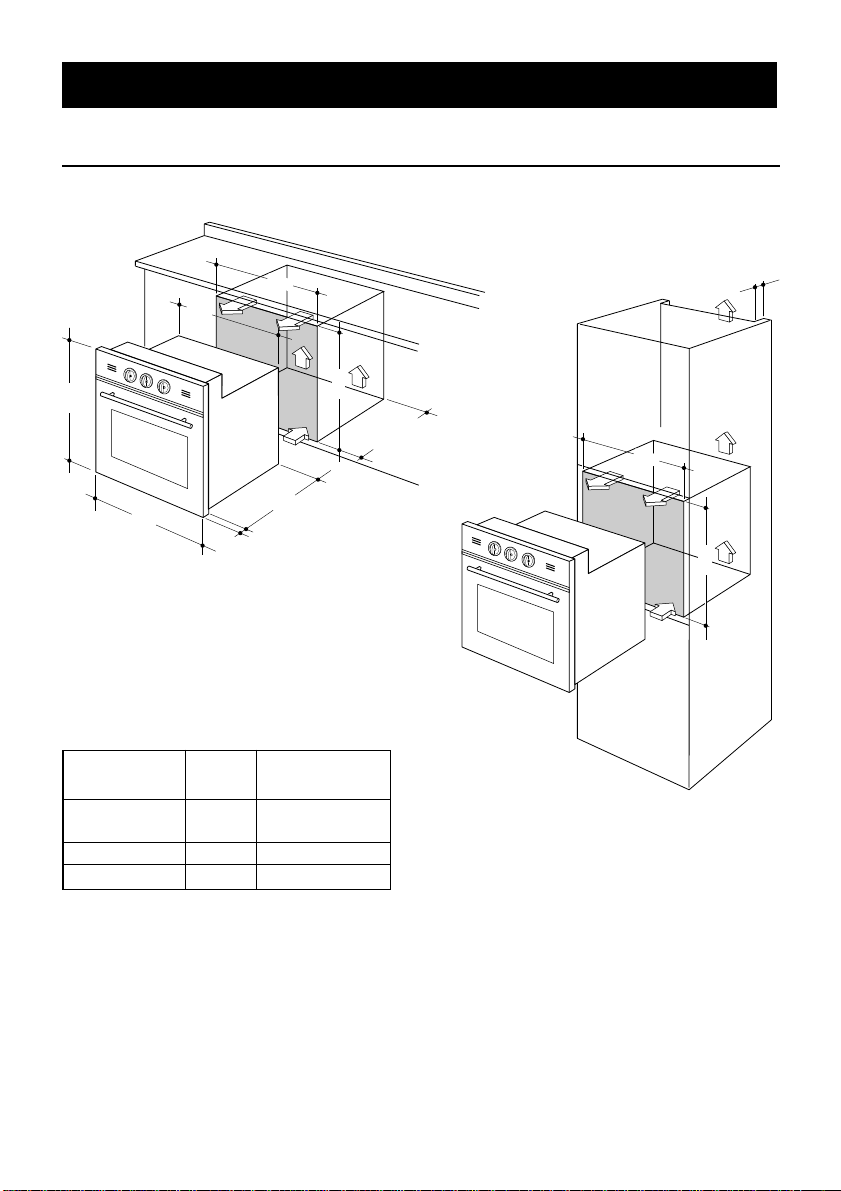
REGULATION OF THE MINIMUM FLAME
(FOR FITTERS USE ONLY)
NOTE: The flame has been regulated for use with Natural Gas, however, when
converting to L.P.G. the flame may need adjusting.
Turn the thermostat to the maximum setting and pre-heat the oven, without grill pan and
base plate, for approximately ten minutes, turn the control to the 1/2 position.
Remove the knob and adjust the thermostat by-pass screw (Fig. 3.4) to obtain a short
sharp stable flame. (The flame is visible through the holes in the oven base).
Check that moving the control knob from the maximum flame position to the 1/2 setting,
or rapidly opening and closing the oven door does not make the flame go out.
G 30 - 28-30 mbar G 20
G31- 37 mbar 20 mbar
OVEN 3,000 0,650 40 83 15 * 125 4 *
Nominal
Power
[kW]
Reduced
Power
[kW]
Ring opening
[mm]
Ø injector
[1/100 mm]
By-pass
[1/100 mm]
Ring opening
[mm]
Ø injector
[1/100 mm]
By-pass
[1/100 mm]
adjustable
*
= Reference value
Page 11
11
G
FLAMES REGULATION OF THE OVEN BURNER
Because of different gas mixtures in the distribution system, you may have flames with
too much or too little air. In such cases, loosen the screw and move the air ring to close
or open the air flow, until the regular flame is obtained (fig. 3.5).
Standard position of the air ring.
Natural Gas: Positioning the indicator line of the air ring to the symbol N printed on the
burner.
L.P.G.: Fully open the air ring.
Warning: The regulation of the flames must only be carried out by a Corgi registered
fitter.
Opening ring [mm]
Page 12

How To Use Your Gas Oven
12
The rating plate can be found on the bottom right hand side of the inner door.
Locate the wire side frames as indicated in Fig. 3.6.
Slide in, on the guides, the shelf and the tray etc. (Fig. 3.7).
Before using the oven for the first time, we recommend that you clean it with soapy
water, rinse carefully and heat for 30 minutes at maximum temperature.
A slightly unpleasant smell may be produced, caused by grease remaining on the oven
elements from the production process.
The kitchen should be well ventilated during this time.
Fig. 3.6
Fig. 3.7
Page 13

13
A B
C
LIGHTING OF OVEN BURNER
The thermostatic tap controlling the gas supply to the burner is equipped with a safety
device which automatically stops the gas flow in case of flame extinction.
The temperature is constantly maintained on the set value.
The electric ignition starts up by pressing the thermostat knob.
A safety device prevents the electric ignition from functioning when the oven door
is shut.
4 - How To Use Your Oven - Control panel
Control panel
A. Temperature Selector/lgnition
B. Grill and Light Selector
C. Timer
Fig. 4.1
A. Temperature Selector/Ignition
Light the oven with the door open,
lightly press and turn the thermostat
knob (A) anti-clockwise to the desired
setting. Press the knob right in to operate the electronic ignition. Hold it in for 10
-15 seconds after the flame has lit.
If the oven fails to light using the electro-
nic ignition it can be lit with a match (fig.
4.2).
If there is a fault refer to APPLIANCE
SERVICING.
Fig. 4.2
Page 14

14
C. Timer
The timer can be set to a maximum of
60 minutes.
Turn the dial clockwise to the maximum
setting of 60 minutes then turn it anticlockwise until it reaches the desired
time fig 4.3.
When the set time expires the timer bell
will sound.
NOTE:
The oven will not switch itself off at the
end of the timed period.
Safety devices
For safety reasons, it is not allowed to use the oven burner and the electric grill together,
at the same time.
The electric grill only operates when the thermostat knob is on position ● (out), as:
–
when the oven burner is alight a safety device stops the ignition of the electric grill
.
–
if the electric grill is on, the same safety device cuts off the element if the thermostat
knob is turned on.
1 - MAX Grill with the door closed. Set the temperature to the desired setting
which can be varied between 1 and max. Before using the grill, pre-heat
for about 5 minutes.
Position the grill pan on the highest shelf position and check continually as
food could easily burn. The indicator light will cycle with the grill element.
Caution: the oven door becomes very hot during operation.
Keep children well out of reach.
B. Grill and Light Selector
LIGHT The light will switch on automatically while grilling and can be selected
when using the oven.
Fig. 4.3
Page 15

15
Your gas oven is a newly designed oven which incorporates an indirect burner located
under the oven base plate.
If you have previously been used to cooking with gas you may need to slightly alter your
cooking methods. The bottom of the oven is hot and is ideal for browning the underside
of shallow pastry dishes and pizzas. Other items should be cooked nearer the top of the
oven.
When baking cakes, scones etc on more than one shelf the best results will be achieved
by swapping the shelf positions over half way through the cooking process.
SAFETY
NEVER allow fat to build on the oven base.
As with all ovens, clean and empty fat regularly from the trays and oven base to avoid
the possibility of fat fires.
The oven contains a tangential fan at the top of the appliance which forces cool air over
the fascia panel when the oven reaches a set temperature to prevent it from becoming
too hot.
The fan will continue to operate after the oven has been switched off, until the appliance
cools down. However, the oven door can become hot - keep children away from this
appliance.
NEVER place anything on the bottom of the oven.
USE OF THE GRILL
Preheat the oven for about 5 minutes with the door closed.
Introduce the food to be cooked, positioning the rack as close to the grill as possible.
The dripping pan should be placed under the rack to catch the cooking juices and fats.
Do not grill for longer than 30 minutes at any one time.
Caution: the oven door becomes very hot during operation. Keep children well out
of reach.
Cooking guide
Page 16

16
Recommended cooking temperature
MARK
APPROX. HEAT OF TYPE OF DISH TO COOK
TEMP. OVEN
1/2 125°C Very cool Meringue cakes,
257°F oven slow cooking items
1 140°C Cool Milk puddings, very rich fruit
275°F oven cakes, i.e., Christmas
2 150°C Cool or Stews, casseroles, braising,
300°F slow oven rich fruit cakes, i.e., Dundee
3 160°C Cool or Biscuits, rich plain cakes
325°F slow oven i.e., Madeira. Low temp. roasting
4 180°C Warm Plain cakes, Victoria
350°F oven sandwich, raised meat pies
5 190°C Moderate Small cakes, savoury flans,
375°F oven fish
6 200°C Fairly hot Plain cakes and buns, swiss rolls,
395°F oven fruit pies. High temp. roasting
7 220°C Hot oven Bread and bread rolls etc., scones,
430°F flaky and rough puff pastry,
yorkshire pudding
8 230°C Moderately Sausage rolls, mince pies, puff
450°F hot oven pastry, pizza
9 240°C Very hot Browning ready cooked dishes
465°F oven
Page 17

17
5 - Cleaning and Maintenance
General
Installation, and any demonstration, information or adjustments are not included in the
warranty.
We recommend that the installation is carried out by qualified personnel.
After use allow the oven to cool and whilst the oven is still “warm” it should be wiped with
a damp cloth using warm soapy water. With regular cleaning the oven will remain in good
condition.
Before cleaning the oven switch it off and wait for it to cool down.
Important:
Before any operation of cleaning and maintenance disconnect the appliance from
the electrical network.
Enamel Parts
In order to maintain the condition of the enamel parts, clean and wipe frequently with hot
soapy water. Any obstinate marks can be removed using a paste or cream cleaner or a
well moistened soap impregnated steel wool pad. Rub gently so as not to damage the
surface.
Never use abrasive powders.
Never permit vinegar, coffee, milk, salt water or tomato juice to remain in contact with the
enamel parts as they may stain or discolour the surface.
If any cleaners such as a spray or a stick are used on enamel they must have the VEDC
(Vitreous Enamel Development Council) seal of approval and the manufacturers
instructions must be followed.
Stainless steel surfaces
CAUTION
The STAINLESS STEEL surfaces used in this oven are protected with a Special Lacquer
to reduce finger-print marks.
To avoid damaging this lacquer, do not clean the stainless steel with abrasive cleaners or
abrasive cloths or scouring pads.
ONLY SOAP/WARM WATER MUST BE USED TO CLEAN THE STAINLESS STEEL
SURFACES.
REPLACING the oven light
To replace the interior oven lamp, unscrew the glass guard and make sure that the new
lamp has identical specifications, i.e. 15 Watts, 300°Centigrade.
Be sure to switch off the electrical supply.
Page 18

18
Do not use a steam cleaner
because the moisture can get into
the appliance thus make it unsafe.
Removal of the inner glass door panel
The inner glass door panel can easily be removed for cleaning by unscrewing the two
screws (figure 5.1).
During re-assembly, ensure that the inner glass is correctly aligned and do not over
tighten the screws.
Fig. 5.1
ATTENTION
The appliance gets very hot, mainly around the cooking areas. It is very
important that children are not left alone in the kitchen when you are cooking.
Page 19

19
Trouble shooting
Problem
Food too brown but not cooked.
Remedy
Turn down the oven temperature slightly
and cook a little longer
Problem
Food cooked but not brown enough.
Remedy
Increase temperature.
Problem
Food baking unevenly.
Remedy
1. The temperature may be slightly high
turn it down
2. Position the food in the centre of the
shelves rather than towards the sides
of tho oven.
3. Rotate the food a half turn in the oven.
4. Try pre-heating the oven for 5-15 min-
utes prior to baking.
Always remove cooked items as soon as
they are ready and continue cooking the
under-cooked items until they are completely finished.
Changing the Oven Cavity Light Bulb.
If the oven light falls:
1. Turn off the oven by switching the
oven selector to 0, switch off and isolate the power.
2. When the oven is cool, reach back
and upwards inside the oven, the bulb
is in the top left corner.
3. Unscrew the light glass cover, replace
the bulb with a new one of the same
specification and screw the cover
back until it is hand tight.
NOTE: Oven bulb replacement is not
covered by your guarantee.
Other bulbs cannot be changed by yourself and should be replaced by an authorised CAPLE Service Engineer.
Bulbs other than the oven bulb are covered by the guarantee.
IMPORTANT: Ovens get hot. Keep
children away from this appliance at
all times.
If you are in any doubt call the CAPLE
Helpline on 0870 241 1142.
A charge will be made if the appliance is
found to be in working order, or if it has
not been installed in accordance with
these instructions, or if it is has been
used incorrectly.
Helpful Advice
Page 20

Cod. 1101894
ß3
CAPLE “Built-in” Service
Should you require service at any time,
please contact the Caple Helpline on
0870 241 1142.
Caple have a nationwide service net-
work of engineers who will respond
quickly to your call.
YOUR GUARANTEE
CAPLE guarantees all parts of this product for one year from the date of pur-
chase. During that time, should it become necessary CAPLE engineers will
replace or repair all defective parts free of charge, except for parts subject to fair
wear and tear, such as lightbulbs.
Parts and the engineers labour costs are chargeable after the first 12 months.
To qualify for benefits under the guarantee, you must be able to provide proof of
date of purchase and the appliance must have been supplied, installed and used
for domestic purposes only in accordance with CAPLE instructions.
Consequential losses and accidental damage to the product are not covered by
the guarantee.
This guarantee does not affect your statutory or common law rights.
CAPLE cannot be responsible for the results of using this appliance for any other
purposes other than those described in these instructions.
Always replace spare parts with genuine
Caple spares. These are available from
authorised Caple Service Centres or by
mail order from our National Service
Stores, simply telephone 0870 241
1142.
When ordering parts always quote the
model number and serial number of your
appliance.
 Loading...