

Page 1

E
UROTHERM
6100A/6180A
User guide
100 and 180 mm paperless graphic recorders
Page 2

E
UROTHERM
Declaration of Conformity
Manufacturer's name: Eurotherm Limited
Manufacturer's address: Faraday Close, Worthing, West Sussex,
BN13 3PL, United Kingdom
Product type: Paperless graphic recorder
Models: 6100A Status level A1 and above
6180A Status level A1 and above
Safety specification: BS EN61010-1: 2001-02
EMC emissions specification: BS EN61326 2002-02
EMC immunity specification: BS EN61326 2002-02
Eurotherm Limited hereby declares that the above products conform to the safety
and EMC specifications listed. Eurotherm Limited further declares that the above products comply with the EMC Directive 89 / 336 / EEC amended by 93 / 68 / EEC, and also
with the Low Voltage Directive 73 / 23 / EEC.
Signed: Dated:
Signed for and on behalf of Eurotherm Limited
William Davis
(General Manager)
IA249986U670 Issue 1 Dec 05 (CN21129)
© 2006 Eurotherm Limited
All rights are strictly reserved. No part of this document may be reproduced, stored in a retrieval system or
transmitted in any form, by any means, without the prior, written permission of the copyright owner.
Eurotherm Limited reserves the right to alter the specification of its products from time to time without
prior notice. Although every effort has been made to ensure the accuracy of the information contained in
this manual, it is not warranted or represented by Eurotherm Limited to be a complete or up-to-date description of the product.
Page 3

100/180 MM PAPERLESS GRAPHIC RECORDER: USER GUIDE
PAPERLESS GRAPHIC RECORDER
USER GUIDE
LIST OF SECTIONS
Section Page
1 INTRODUCTION ................................................................................... 2
2 INSTALLATION ...................................................................................... 2
3 PROCESS VARIABLE DISPLAY ................................................................. 14
4 SETTING UP THE RECORDER ................................................................. 51
5 FILE ..................................................................................................... 221
6 BRIDGE ................................................................................................ 225
7 SCREEN BUILDER .................................................................................. 234
8 MODBUS TCP SLAVE COMMS ............................................................... 262
9 ANALOGUE OUTPUTS .......................................................................... 314
10 EVENT INPUTS ................................................................................... 316
11 TRANSMITTER POWER SUPPLY ............................................................ 317
12 ASCII PRINTER .................................................................................... 320
13 PORTABLE CASE OPTIONS .................................................................. 330
ANNEX A: SPECIFICATION ....................................................................... 341
ANNEX B: REFERENCE ............................................................................ 349
ANNEX C: WEB SERVER DETAILS .............................................................. 379
INDEX ..................................................................................................... 383
EFFECTIVITY
This manual refers to recorders fitted with software version 4.1 To determine the software version fitted to the recorder, the 'About' screen in the System menu may be accessed as described in section 4.6.11.
Cont...
HA028910
Issue 3 Jun 06
User Guide
Page i
Page 4

Cont...
100/180 MM PAPERLESS GRAPHIC RECORDER: USER GUIDE
PAPERLESS GRAPHICS RECORDER USER GUIDE
LIST OF CONTENTS
Section Page
Safety Notes ....................................................................................................... 1
SYMBOLS USED ON THE RECORDER LABELLING .................................................. 1
1 INTRODUCTION ................................................................................. 2
1.1 UNPACKING THE RECORDER ....................................................................... 2
2 INSTALLATION ................................................................................... 2
2.1 MECHANICAL INSTALLATION ...................................................................... 2
2.2 ELECTRICAL INSTALLATION .......................................................................... 5
2.2.1 Signal wiring ..................................................................................................... 5
CONNECTOR WIRING DETAILS ........................................................................ 5
2.2.2 Supply voltage wiring .......................................................................................... 9
LINE SUPPLY ..................................................................................................... 9
LOW VOLTAGE SUPPLY OPTION ........................................................................ 9
2.3 ACCESS FLAP .............................................................................................. 10
2.3.1 Stylus ................................................................................................................ 11
2.3.2 Card slot ........................................................................................................... 11
LED INDICATORS.............................................................................................. 11
2.3.3 USB Front Port .................................................................................................... 11
2.4 LOCKABLE FLAP OPTION ............................................................................. 12
2.4.1 Flap lock operation............................................................................................. 12
ARCHIVE INACTIVE .......................................................................................... 12
ARCHIVE ACTIVE .............................................................................................. 13
3 PROCESS VARIABLE DISPLAY .............................................................. 14
TRUNCATION OF NUMERIC VALUES ................................................................. 14
CURRENT TRACE ALARM ICONS ....................................................................... 15
3.1 STATUS BAR ................................................................................................ 15
3.1.1 Current access level ............................................................................................ 15
3.1.2 Page name ........................................................................................................ 15
3.1.3 Alarm indication ................................................................................................ 16
INSTRUMENT ALARM ....................................................................................... 16
CHANNEL ALARM ............................................................................................ 18
CHANGE BATTERY ........................................................................................... 18
DISK ICON ...................................................................................................... 18
FTP ICON ........................................................................................................ 18
CONFIGURATION LOCKED INDICATOR ............................................................ 18
TRIAL MODE INDICATOR .................................................................................. 18
3.1.4 Summary menu .................................................................................................. 19
INSTRUMENT ALARM SUMMARY ...................................................................... 19
ACK ALL ALARMS ............................................................................................. 19
ALARM SUMMARY PAGE .................................................................................. 20
ALARM ACKNOWLEDGEMENT ......................................................................... 21
BATCH SUMMARY ............................................................................................ 22
MESSAGE LOG ................................................................................................ 24
REMOVE MEDIA ............................................................................................... 27
3.2 NAVIGATION Keys ...................................................................................... 28
3.2.1 Key functions ..................................................................................................... 28
ROOT MENU KEYS ........................................................................................... 28
ALARM SUMMARY ........................................................................................... 30
MESSAGE LOG ................................................................................................ 30
3.3 FIRST SWITCH-ON ....................................................................................... 31
3.3.1 Access to Configuration ...................................................................................... 32
TEXT STRING ENTRY ......................................................................................... 33
3.4 DISPLAY MODES .......................................................................................... 35
3.4.1 Vertical Trend display ......................................................................................... 35
TIME CHANGE RECORDS ................................................................................. 36
TREND HISTORY ............................................................................................... 36
User Guide
Page ii
HA028910
Issue 3 Jun 06
Page 5

Cont...
100/180 MM PAPERLESS GRAPHIC RECORDER: USER GUIDE
LIST OF CONTENTS (Cont.)
Section Page
3.4.2 Horizontal Trend display ..................................................................................... 38
3.4.3 Circular Trend .................................................................................................... 40
TREND MODES ................................................................................................ 40
NORMAL VIEW ................................................................................................ 41
NORMAL VIEW FEATURES ................................................................................ 42
FULL SCREEN DISPLAY ....................................................................................... 42
FULL SCREEN FEATURES.................................................................................... 42
TIMESTAMPS .................................................................................................... 43
OTHER NOTES ................................................................................................. 43
3.4.4 Vertical bargraph ................................................................................................ 44
FACEPLATES ABOVE THE BARS .......................................................................... 44
FACEPLATES AT RIGHT-HAND EDGE ................................................................... 44
3.4.5 Horizontal bargraph ........................................................................................... 46
3.4.6 Numeric ............................................................................................................ 48
3.5 OPERATOR NOTES ...................................................................................... 50
4 SETTING UP THE RECORDER ............................................................... 51
4.1 ARCHIVE ..................................................................................................... 52
4.1.1 Local Archive ..................................................................................................... 52
BRING ARCHIVE UP TO DATE............................................................................ 53
ARCHIVE ALL .................................................................................................... 53
ARCHIVING WITH THE LOCKABLE FLAP OPTION ............................................... 53
4.1.2 Remote archiving (FTP transfer) ............................................................................ 54
4.2 SAVE / RESTORE ......................................................................................... 55
4.2.1 Save ................................................................................................................. 56
SAVE AS .......................................................................................................... 56
4.2.2 Restore .............................................................................................................. 56
4.2.3 New ................................................................................................................. 56
4.2.4 Text ................................................................................................................... 56
4.2.5 Import screen ..................................................................................................... 56
4.2.6 Export screen ..................................................................................................... 57
4.2.7 Import User Linearisation ..................................................................................... 57
4.2.8 Export User Linearisation ..................................................................................... 57
4.2.9 Import printer driver ............................................................................................ 57
4.3 CONFIG KEY ............................................................................................... 58
4.3.1 Instrument configuration ...................................................................................... 63
INSTRUMENT NAME ........................................................................................ 63
NORMAL/SAVER DISPLAY ................................................................................. 63
SAVE AFTER ..................................................................................................... 63
MODBUS ADDRESS .......................................................................................... 63
MODBUS SECURITY DISABLED .......................................................................... 63
COMMS CHANNEL TIMEOUT ........................................................................... 63
PRESET HOUR .................................................................................................. 64
PRESET MINUTE ................................................................................................ 64
DISABLE WARNING DIALOGS ........................................................................... 64
SHOW OPERATOR NOTES LIST ......................................................................... 64
4.3.2 Group configuration ........................................................................................... 65
GROUP NUMBER ............................................................................................. 66
TREND UNITS ................................................................................................... 66
DESCRIPTOR .................................................................................................... 66
TREND TYPE ..................................................................................................... 66
A/B SWITCHING ............................................................................................. 67
TREND SPEED/TREND INTERVAL ........................................................................ 67
CIRCULAR SETTINGS ........................................................................................ 67
CIRCULAR SPEED .............................................................................................. 67
CIRCULAR CHART FULL ..................................................................................... 67
START AT .......................................................................................................... 67
GRID TYPE........................................................................................................ 68
RECORDING ENABLE ....................................................................................... 68
RECORDING SPEED/RECORDING INTERVAL ...................................................... 69
TREND HISTORY DURATION .............................................................................. 69
ARCHIVE TO MEDIA ENABLE/ARCHIVE VIA FTP ENABLE .................................... 69
HA028910
Issue 3 Jun 06
User Guide
Page iii
Page 6

100/180 MM PAPERLESS GRAPHIC RECORDER: USER GUIDE
LIST OF CONTENTS (Cont.)
Section Page
4.3.2 Group configuration (Cont.)
ALARM MESSAGE ............................................................................................ 69
ACK MESSAGE ................................................................................................ 69
POINT TYPE/SELECTION ................................................................................... 70
4.3.3 Channel/Alarm configuration .............................................................................. 71
CHANNEL NUMBER ......................................................................................... 72
VALUE .............................................................................................................. 72
INPUT TYPE ...................................................................................................... 72
LIN TYPE .......................................................................................................... 72
INPUT LOW ..................................................................................................... 72
INPUT HIGH ..................................................................................................... 72
SHUNT ............................................................................................................ 73
RANGE LOW ................................................................................................... 73
RANGE HIGH................................................................................................... 73
RANGE UNITS.................................................................................................. 73
SCALED ........................................................................................................... 73
OFFSET ............................................................................................................ 73
SCALE TYPE...................................................................................................... 74
FILTER............................................................................................................... 76
BREAK RESPONSE ............................................................................................ 76
COLD JUNCTION COMPENSATION (CJC) ......................................................... 76
DESCRIPTOR .................................................................................................... 76
A/B SWITCHING ............................................................................................. 76
SPANNED ........................................................................................................ 77
ZONE .............................................................................................................. 77
PV FORMAT...................................................................................................... 77
MAXIMUM DECIMAL DIGITS ............................................................................. 77
COLOUR .......................................................................................................... 77
ALARM NUMBER .............................................................................................. 77
ENABLE ........................................................................................................... 78
TYPE ................................................................................................................ 78
SETPOINT SOURCE .......................................................................................... 78
PARAMETERS .................................................................................................... 79
HYSTERESIS EXAMPLE ....................................................................................... 79
RATE-OF CHANGE ALARM EXAMPLE ................................................................. 79
JOB NUMBER ................................................................................................... 81
CATEGORY ...................................................................................................... 81
WHILE/ON ...................................................................................................... 81
ALARM MESSAGES .......................................................................................... 81
4.3.4 Views Configuration ........................................................................................... 82
HOME TIMEOUT .............................................................................................. 82
HOME GROUP ................................................................................................. 82
SCOPE ............................................................................................................. 82
GROUP ............................................................................................................ 83
DISPLAY ENABLE ............................................................................................... 83
HOME PAGE .................................................................................................... 83
DISPLAY MODE ENABLING ............................................................................... 83
USER SCREENS 1 to N ...................................................................................... 84
Cont...
User Guide
Page iv
HA028910
Issue 3 Jun 06
Page 7

100/180 MM PAPERLESS GRAPHIC RECORDER: USER GUIDE
LIST OF CONTENTS (Cont.)
Section Page
4.3.5 Archive configuration ......................................................................................... 85
COMPRESSION ................................................................................................ 86
FLASH SIZE ...................................................................................................... 86
SHORTEST TREND HISTORY / DURATION .......................................................... 86
CSV CHECK BOXES, DATE/TIME FORMAT ......................................................... 86
SHOW ............................................................................................................ 86
MEDIA ............................................................................................................. 86
ARCHIVE TO MEDIA ......................................................................................... 86
MEDIA FILE FORMAT/FTP FILE FORMAT .............................................................. 87
ON MEDIA FULL ............................................................................................... 87
MEDIA SIZE ...................................................................................................... 87
REMOVABLE MEDIA CAPACITY.......................................................................... 87
MEDIA FULL EVENT LIMIT .................................................................................. 87
ARCHIVE TO REMOTE....................................................................................... 87
REMOTE PATH .................................................................................................. 87
PRIMARY REMOTE HOST................................................................................... 88
PRIMARY LOGIN NAME/PASSWORD ................................................................ 88
SECONDARY REMOTE HOST/LOGIN/PASSWORD ............................................ 88
CSV FILES......................................................................................................... 88
4.3.6 Event configuration ............................................................................................. 90
EVENT NUMBER ............................................................................................... 90
SOURCE TYPES ................................................................................................ 90
SOURCE 1 SENSE ............................................................................................ 91
OPERATOR ....................................................................................................... 92
SOURCE 2 SENSE ............................................................................................ 92
DESCRIPTOR .................................................................................................... 92
JOB NUMBER ................................................................................................... 92
CATEGORY ...................................................................................................... 92
WHILE/ON ...................................................................................................... 92
EVENT EXAMPLE............................................................................................... 92
4.3.7 Event Buttons ...................................................................................................... 93
4.3.8 Messages .......................................................................................................... 94
MESSAGE ENTRY ............................................................................................. 94
CONFIGURABLE PARAMETERS .......................................................................... 94
EXAMPLE.......................................................................................................... 96
4.3.9 User Linearisation Tables ..................................................................................... 97
CONFIGURATION PARAMETERS ....................................................................... 97
4.3.10 Batch recording option ..................................................................................... 99
AUDITOR MESSAGES ....................................................................................... 99
BATCH SUMMARY ............................................................................................ 99
CONFIGURATION ............................................................................................ 100
OPERATOR INITIATION ..................................................................................... 102
NON OPERATOR INITIATION ............................................................................ 105
EVENT SOURCES ............................................................................................. 105
4.3.11 Maths .............................................................................................................. 106
CONFIGURATION ............................................................................................ 106
MODBUS ADDRESSING .................................................................................... 132
4.3.12 Totalisers ......................................................................................................... 135
INTRODUCTION............................................................................................... 135
CONFIGURATION ............................................................................................ 135
4.3.13 Counters .......................................................................................................... 140
INTRODUCTION............................................................................................... 140
CONFIGURATION ............................................................................................ 140
COUNTER MODBUS ADDRESSING ................................................................... 141
4.3.14 Timers .............................................................................................................. 144
INTRODUCTION............................................................................................... 144
CONFIGURATION ............................................................................................ 144
SELF-START EXAMPLE ......................................................................................... 145
Cont...
HA028910
Issue 3 Jun 06
User Guide
Page v
Page 8

100/180 MM PAPERLESS GRAPHIC RECORDER: USER GUIDE
LIST OF CONTENTS (Cont.)
Section Page
4.3.15 Connections ..................................................................................................... 146
INTRODUCTION............................................................................................... 146
INSTALLATION.................................................................................................. 146
TERMINATION AND BIASSING (Not EIA232)..................................................... 146
CONFIGURATION ............................................................................................ 147
CONFIGURATION PARAMETERS ....................................................................... 148
MESSAGING INFORMATION............................................................................ 149
MODBUS ADDRESS .......................................................................................... 149
4.3.16 Master comms .................................................................................................. 150
INTRODUCTION............................................................................................... 150
MASTER COMMS CONFIGURATION MENU ...................................................... 151
DETECT THIS SLAVE .......................................................................................... 152
DETECT ALL SLAVES .......................................................................................... 153
SHARE SOCKET ................................................................................................ 155
MASTER COMMS CHANNEL CONFIGURATION ................................................ 156
STATUS BITS ..................................................................................................... 162
MASTER COMMS CHANNEL CONFIGURATION EXAMPLE.................................. 164
MASTER CHANNEL 1 SETUP ............................................................................. 165
MASTER CHANNEL 2 SETUP ............................................................................. 166
MASTER OUTPUT 1 SETUP ................................................................................ 167
SLAVE INPUT CHANNEL 1 SETUP ...................................................................... 167
MASTER COMMS DIAGNOSTICS ...................................................................... 168
4.3.17 Output channels ............................................................................................... 169
MASTER COMMS ............................................................................................. 169
ANALOGUE OUTPUTS (RETRANSMISSION) ....................................................... 170
4.3.18 Demand Writes ................................................................................................ 171
DEMAND WRITE CONFIGURATION .................................................................. 171
WRITING TO A SPECIFIC REGISTER ................................................................... 173
4.3.19 E-mails ............................................................................................................ 175
E-MAIL CONFIGURATION ................................................................................. 175
CONFIGURABLE PARAMETERS .......................................................................... 176
E-MAIL DETAILS................................................................................................. 177
OPERATION ..................................................................................................... 178
4.3.20 Reports configuration ........................................................................................ 179
REPORT ............................................................................................................ 179
DESCRIPTOR .................................................................................................... 179
NUMBER OF FIELDS .......................................................................................... 179
FIELD N TYPE .................................................................................................... 179
STYLE ............................................................................................................... 180
POINT ............................................................................................................. 180
LINE FEED ........................................................................................................ 180
4.3.21 Options ........................................................................................................... 181
TRIAL MODE..................................................................................................... 182
VIRTUAL CHANNELS ......................................................................................... 182
SIMULATION OPTION ....................................................................................... 182
Cont...
User Guide
Page vi
HA028910
Issue 3 Jun 06
Page 9

100/180 MM PAPERLESS GRAPHIC RECORDER: USER GUIDE
LIST OF CONTENTS (Cont.)
Section Page
4.4 SECURITY .................................................................................................... 183
4.4.1 Access levels ...................................................................................................... 184
SETTING PERMISSIONS .................................................................................... 184
ACCESS WHEN: .............................................................................................. 185
NEW PASSWORD/RETYPE PASSWORD ............................................................. 185
CONNECT FROM REMOTE ............................................................................... 185
REMOTE USER NAME/REMOTE PASSWORD ..................................................... 185
LOGIN DISABLED ............................................................................................. 185
EDIT OWN PASSWORD.................................................................................... 185
CHANGE ALARM SETPOINTS............................................................................ 185
ACKNOWLEDGE ALARMS ................................................................................ 186
EDIT MATHS CONSTANT .................................................................................. 186
RESET MATHS ................................................................................................... 186
PRESET TOTALISERS .......................................................................................... 186
PRESET COUNTERS .......................................................................................... 186
START/RESET TIMERS ........................................................................................ 186
SET CLOCK ...................................................................................................... 186
ADJUST I/O ..................................................................................................... 186
ARCHIVING CONTROL ..................................................................................... 186
SAVE/RESTORE ................................................................................................ 186
PASTE/DELETE FILES .......................................................................................... 186
FULL CONFIGURATION..................................................................................... 186
FULL SECURITY ................................................................................................. 186
BATCH CONTROL ............................................................................................ 186
CAN SIGN....................................................................................................... 187
CAN AUTHORIZE ............................................................................................. 187
PERFORM UPGRADES ....................................................................................... 187
EVENT PERMISSION 1 ...................................................................................... 187
EVENT PERMISSION 2 TO 5.............................................................................. 187
EDIT OUTPUT CHANNEL DEFAULT...................................................................... 187
ACTION DEMAND WRITES ............................................................................... 187
FORCE CHANGE OF PASSWORD ..................................................................... 188
ENTER BATCH DATA ......................................................................................... 188
ALLOW WEB SERVER........................................................................................ 188
4.4.2 Management (option) ......................................................................................... 189
CHANGES NOT RECORDED ............................................................................. 189
CONFIGURABLE PARAMETERS .......................................................................... 190
4.4.3 Add user ........................................................................................................... 194
NEW USER ID .................................................................................................. 194
NEW FULL USER NAME .................................................................................... 194
NEW PASSWORD/RETYPE PASSWORD ............................................................. 194
BASED ON ...................................................................................................... 194
4.4.4 Remove user ...................................................................................................... 194
4.5 NETWORK KEY ........................................................................................... 195
4.5.1 Address ............................................................................................................. 195
INSTRUMENT NUMBER/MAC ADDRESS ............................................................ 195
IP ADDRESS LOOKUP ........................................................................................ 195
BOOTP TIMEOUT.............................................................................................. 195
IP ADDRESS...................................................................................................... 195
SUBNET MASK ................................................................................................. 196
DEFAULT GATEWAY .......................................................................................... 196
SNTP SERVER ENABLE....................................................................................... 196
SNTP CLIENT ENABLE ....................................................................................... 196
SNTP SERVER ................................................................................................... 196
EUROPRP SERVER ENABLE................................................................................. 196
4.5.2 Name ............................................................................................................... 197
LOCAL HOST ................................................................................................... 197
DOMAIN ......................................................................................................... 197
DOMAIN NAME SERVICE (DNS) ....................................................................... 197
PRIMARY/SECONDARY DNS SERVER ................................................................ 197
Cont...
HA028910
Issue 3 Jun 06
User Guide
Page vii
Page 10

100/180 MM PAPERLESS GRAPHIC RECORDER: USER GUIDE
LIST OF CONTENTS (Cont.)
Section Page
4.6 SYSTEM ...................................................................................................... 198
4.6.1 Clock ................................................................................................................ 200
4.6.2 Locale ............................................................................................................... 200
LONG DATE FORMAT ....................................................................................... 200
4.6.3 Upgrade ............................................................................................................ 201
4.6.4 Input adjust ........................................................................................................ 202
ADJUST PROCEDURE ........................................................................................ 203
4.6.5 Output Adjust ..................................................................................................... 204
4.6.6 Master Comms Diagnostics ................................................................................. 204
4.6.7 Ethernet Diagnostics ........................................................................................... 204
4.6.8 Copy ................................................................................................................. 205
CONFIGURABLE PARAMETERS .......................................................................... 205
COPY RULES .................................................................................................... 206
4.6.9 Job search ......................................................................................................... 207
SEARCH RESULTS.............................................................................................. 207
4.6.10 Customise ........................................................................................................ 208
FONT SIZE EXAMPLES....................................................................................... 209
4.6.11 About .............................................................................................................. 210
INSTRUMENT VARIANT ..................................................................................... 210
CONFIG REVISION .......................................................................................... 210
LAST UPDATED ................................................................................................. 210
AT VERSION..................................................................................................... 210
CREATED ON ................................................................................................... 210
SECURITY REVISION ......................................................................................... 211
SUPPORT FILE ................................................................................................... 211
4.7 JOBS .......................................................................................................... 212
4.7.1 No Action.......................................................................................................... 212
4.7.2 Drive relay category ........................................................................................... 212
4.7.3 Totaliser category ............................................................................................... 212
4.7.4 Message category .............................................................................................. 213
4.7.5 Maths category .................................................................................................. 213
4.7.6 Clock category ................................................................................................... 214
4.7.7 Counter category ............................................................................................... 214
4.7.8 Timer category ................................................................................................... 215
4.7.9 Batch category ................................................................................................... 215
4.7.10 Recording category .......................................................................................... 216
4.7.11 Trend category ................................................................................................. 217
4.7.12 Output category ............................................................................................... 218
4.7.13 Demand Writes category .................................................................................. 218
4.7.14 Alarm category ................................................................................................ 219
4.7.15 Archive category .............................................................................................. 219
4.7.16 Email category ................................................................................................. 220
4.7.17 Report category ............................................................................................... 220
SEND REPORT TO ............................................................................................. 220
GROUP ............................................................................................................ 220
REPORT ............................................................................................................ 220
5 FILE ................................................................................................... 221
5.1 FILER OPTION MENU KEYS .......................................................................... 221
5.2 THE HIDE KEY ............................................................................................. 221
5.3 FILE STRUCTURE .......................................................................................... 223
Cont...
User Guide
Page viii
HA028910
Issue 3 Jun 06
Page 11

100/180 MM PAPERLESS GRAPHIC RECORDER: USER GUIDE
LIST OF CONTENTS (Cont.)
Section Page
6 BRIDGE (REMOTE VIEWER) ................................................................. 225
6.1 INTRODUCTION.......................................................................................... 225
6.1.1 Minimum PC requirements ................................................................................... 226
SUPPORTED PDA CONFIGURATION .................................................................. 226
6.2 CONNECTION DETAILS ............................................................................... 227
6.2.1 Direct PC connection .......................................................................................... 227
6.2.2 PC To remote recorder ........................................................................................ 227
6.2.3 Networked systems ............................................................................................. 227
6.3 SOFTWARE INSTALLATION ........................................................................... 228
6.4 RECORDER CONFIGURATION...................................................................... 228
6.4.1 Network ............................................................................................................ 228
6.4.2 Options ............................................................................................................. 228
6.4.3 Access............................................................................................................... 229
6.5 RUNNING THE PROGRAM........................................................................... 230
CHANNEL ALARM SOUND ............................................................................... 231
6.6 OPERATION ................................................................................................ 232
6.6.1 Display Modes ................................................................................................... 232
6.6.2 Alarm acknowledgement ..................................................................................... 232
6.6.3 Status line .......................................................................................................... 232
6.6.4 Error messages ................................................................................................... 233
NETWORK CONNECTION HAS TIMED OUT ..................................................... 233
UNABLE TO CONNECT TO HOST ... ................................................................. 233
UNABLE TO RESOLVE HOSTNAME .................................................................... 233
FAILED TO AUTHENTICATE THE USER NAME ..................................................... 233
MAXIMUM NUMBER OF BRIDGE SESSIONS ALREADY RUNNING ON ... ............ 233
THERE APPEARS TO BE NO FREE DISK SPACE ON ... ......................................... 233
YOU ARE ALREADY RUNNING A FULL BRIDGE SESSION ... ................................ 233
YOU ARE AUTHENTICATING FULL BRIDGE ... ..................................................... 233
7 SCREEN BUILDER................................................................................ 234
7.1 INTRODUCTION.......................................................................................... 234
7.1.1 Display Access ................................................................................................... 235
7.1.2 Importing/Exporting screens ................................................................................ 235
IMPORTING SCREENS ...................................................................................... 236
EXPORTING SCREENS ...................................................................................... 236
7.2 DISPLAY CREATION ..................................................................................... 236
7.2.1 Before starting ................................................................................................... 236
7.2.2 Screen components ............................................................................................ 237
7.2.3 The properties page ........................................................................................... 238
KEY DESCRIPTIONS (UPPER KEYS) ..................................................................... 238
KEY DESCRIPTIONS (LOWER KEYS) ................................................................... 239
OPTIONS PAGE ITEMS...................................................................................... 240
7.2.4 Screen creation example ..................................................................................... 241
PROCEDURE ..................................................................................................... 241
7.3 PARAMETER DEFINITIONS ............................................................................ 245
7.3.1 Basic parameters ................................................................................................ 245
7.3.2 Advanced parameters ......................................................................................... 247
Cont...
HA028910
Issue 3 Jun 06
User Guide
Page ix
Page 12

100/180 MM PAPERLESS GRAPHIC RECORDER: USER GUIDE
LIST OF CONTENTS (Cont.)
Section Page
7.4 COMPONENT DEFINITIONS ........................................................................ 253
7.4.1 Group Vertical/Horizontal Trend.......................................................................... 253
7.4.2 Group vertical bargraph ..................................................................................... 253
7.4.3 Group horizontal bargraph ................................................................................. 253
7.4.4 Group numeric display ....................................................................................... 254
7.4.5 Channel vertical/horizontal bargraph .................................................................. 254
7.4.6 Channel Numeric ............................................................................................... 254
7.4.7 Channel data ..................................................................................................... 254
7.4.8 Dialogue Action ................................................................................................. 254
7.4.9 Navigation Action .............................................................................................. 254
7.4.10 Operator button ............................................................................................... 255
7.4.11 Event Button ..................................................................................................... 255
7.4.12 Image ............................................................................................................. 255
7.4.13 Text ................................................................................................................. 256
7.4.14 Round rectangle ............................................................................................... 256
7.4.15 Rectangle ........................................................................................................ 256
7.4.16 Polyline - series of points ................................................................................... 257
7.4.17 Polygon - closed area ....................................................................................... 258
7.4.18 Oval ............................................................................................................... 259
7.4.19 Line .................................................................................................................. 259
EXAMPLE.......................................................................................................... 259
7.4.20 Arc ................................................................................................................. 260
EXAMPLE.......................................................................................................... 260
7.5 MEASURING UNIT COMPARISONS .............................................................. 261
7.5.1 XGA screen ....................................................................................................... 261
7.5.2 QVGA screen .................................................................................................... 261
7.6 ERROR CODES ............................................................................................ 261
8 MODBUS TCP SLAVE COMMS ............................................................. 262
8.1 INSTALLATION............................................................................................. 262
8.2 INTRODUCTION.......................................................................................... 262
8.2.1 Function Codes .................................................................................................. 262
DIAGNOSTIC CODES ....................................................................................... 262
EXCEPTION CODES .......................................................................................... 263
8.2.2 Data types ......................................................................................................... 263
DATA ENCODING ............................................................................................ 263
8.2.3 Invalid multiple register writes .............................................................................. 263
8.2.4 Security ............................................................................................................. 263
TO SEND A LOGIN REQUEST............................................................................ 266
8.2.5 Text messages .................................................................................................... 268
LONG MESSAGES............................................................................................ 268
8.3 ADDRESS MAP ............................................................................................ 270
8.4 ADDRESS ALLOCATION ............................................................................... 272
8.4.1 Instrument data .................................................................................................. 272
8.4.2 Channel configuration data ................................................................................. 273
CHANNEL 1 .................................................................................................... 273
CHANNEL 2 .................................................................................................... 274
CHANNEL 3 .................................................................................................... 275
CHANNEL 4 .................................................................................................... 276
CHANNEL 5 .................................................................................................... 277
CHANNEL 6 .................................................................................................... 278
CHANNEL 7 .................................................................................................... 279
CHANNEL 8 .................................................................................................... 280
CHANNEL 9 .................................................................................................... 281
CHANNEL 10 .................................................................................................. 282
CHANNEL 11 .................................................................................................. 283
CHANNEL 12 .................................................................................................. 284
Cont...
User Guide
Page x
HA028910
Issue 3 Jun 06
Page 13

Cont...
Cont...
100/180 MM PAPERLESS GRAPHIC RECORDER: USER GUIDE
LIST OF CONTENTS (Cont.)
Section Page
8.4.3 Channel Run-Time data ....................................................................................... 285
CHANNEL 1 .................................................................................................... 285
CHANNEL 2 .................................................................................................... 285
CHANNEL 3 .................................................................................................... 286
CHANNEL 4 .................................................................................................... 286
CHANNEL 5 .................................................................................................... 287
CHANNEL 6 .................................................................................................... 287
CHANNEL 7 .................................................................................................... 288
CHANNEL 8 .................................................................................................... 288
CHANNEL 9 .................................................................................................... 289
CHANNEL 10 .................................................................................................. 289
CHANNEL 11 .................................................................................................. 290
CHANNEL 12 .................................................................................................. 290
8.4.4 Group data ....................................................................................................... 291
GROUP 1 ......................................................................................................... 291
GROUP 2 ......................................................................................................... 292
GROUP 3 ......................................................................................................... 293
GROUP 4 ......................................................................................................... 294
GROUP 5 ......................................................................................................... 295
GROUP 6 ......................................................................................................... 296
8.4.5 Feature identification table (FIT) ........................................................................... 297
8.4.6 Indirection tables ................................................................................................ 297
8.4.7 IEEE 32-bit channel configuration data ................................................................. 300
CHANNEL 1 .................................................................................................... 300
CHANNEL 2 .................................................................................................... 300
CHANNEL 3 .................................................................................................... 300
CHANNEL 4 .................................................................................................... 301
CHANNEL 5 .................................................................................................... 301
CHANNEL 6 .................................................................................................... 301
CHANNEL 7 .................................................................................................... 302
CHANNEL 8 .................................................................................................... 302
CHANNEL 9 .................................................................................................... 302
CHANNEL 10 .................................................................................................. 303
CHANNEL 11 .................................................................................................. 303
CHANNEL 12 .................................................................................................. 303
8.4.8 IEEE Area Channel run-time data ......................................................................... 304
CHANNEL 1 .................................................................................................... 304
CHANNEL 2 .................................................................................................... 304
CHANNEL 3 .................................................................................................... 305
CHANNEL 4 .................................................................................................... 305
CHANNEL 5 .................................................................................................... 306
CHANNEL 6 .................................................................................................... 306
CHANNEL 7 .................................................................................................... 307
CHANNEL 8 .................................................................................................... 307
CHANNEL 9 .................................................................................................... 308
CHANNEL 10 .................................................................................................. 308
CHANNEL 11 .................................................................................................. 309
CHANNEL 12 .................................................................................................. 309
8.4.9 Permanent ID table ............................................................................................. 310
8.5 DATA TRANSMISSION ................................................................................. 310
FUNCTION CODES AND EXCEPTION CODES ................................................... 310
TEXT STRINGS .................................................................................................. 310
8.5.1 Function code 03 ............................................................................................... 311
REQUEST ......................................................................................................... 311
RESPONSE ....................................................................................................... 311
EXCEPTION RESPONSES................................................................................... 311
8.5.2 Function code 04 ............................................................................................... 312
8.5.3 Function code 06 ............................................................................................... 312
REQUEST ......................................................................................................... 312
RESPONSE ....................................................................................................... 312
EXCEPTION RESPONSES................................................................................... 312
HA028910
Issue 3 Jun 06
User Guide
Page xi
Page 14

100/180 MM PAPERLESS GRAPHIC RECORDER: USER GUIDE
LIST OF CONTENTS (Cont.)
Section Page
8.5.4 Function code 08 ............................................................................................... 312
8.5.5 Function code 16 (Hex 10) ................................................................................. 313
REQUEST ......................................................................................................... 313
RESPONSE ....................................................................................................... 313
EXCEPTION RESPONSES................................................................................... 313
9 ANALOGUE OUTPUT OPTION ............................................................ 314
9.1 SIGNAL WIRING ......................................................................................... 314
9.2 SPECIFICATION ........................................................................................... 314
9.3 CONFIGURATION ....................................................................................... 314
9.4 OUTPUT ADJUST .......................................................................................... 314
9.4.1 Adjustment procedure ......................................................................................... 314
9.4.2 Adjustment removal ............................................................................................ 314
10 EVENT INPUT OPTION ..................................................................... 316
10.1 INTRODUCTION........................................................................................ 316
10.2 SIGNAL WIRING ....................................................................................... 316
10.3 SPECIFICATION ......................................................................................... 316
11 TRANSMITTER POWER SUPPLY ......................................................... 317
11.1 INTRODUCTION........................................................................................ 317
11.2 FUSING .................................................................................................... 317
11.2.1 Fuse Rating ...................................................................................................... 317
11.2.2 Access to the user connections/fuse ................................................................... 317
11.2.3 User wiring ...................................................................................................... 319
12 ASCII PRINTER OUTPUT OPTION ...................................................... 320
12.1 INTRODUCTION........................................................................................ 320
12.2 WIRING.................................................................................................... 320
12.2.1 Serial communications ports .............................................................................. 320
12.2.2 DC connection ................................................................................................. 320
12.3 Configuration ............................................................................................ 321
12.3.1 Connections ..................................................................................................... 321
PORT ............................................................................................................... 321
LINK ERROR COUNT ........................................................................................ 321
PROTOCOL ...................................................................................................... 322
BAUD RATE ...................................................................................................... 322
STOP BITS ........................................................................................................ 322
PARITY ............................................................................................................. 322
PRINTER TYPE ................................................................................................... 322
PRINTER NAME ................................................................................................ 322
PRINTER STATUS ............................................................................................... 322
PRINTER TEST ................................................................................................... 322
PRINT MESSAGES FROM .................................................................................. 322
MESSAGES TO PRINT ....................................................................................... 322
12.3.2 Reports configuration ........................................................................................ 323
REPORT ............................................................................................................ 323
DESCRIPTOR .................................................................................................... 323
NUMBER OF FIELDS .......................................................................................... 323
FIELD N TYPE .................................................................................................... 323
STYLE ............................................................................................................... 324
POINT ............................................................................................................. 324
LINE FEED ........................................................................................................ 324
12.4 IMPORTING PRINTER DRIVERS .................................................................... 325
12.5 REPORT EXAMPLE ...................................................................................... 326
12.5.1 Group Configuration ........................................................................................ 326
GROUP NUMBER 1 .......................................................................................... 326
Cont...
User Guide
Page xii
HA028910
Issue 3 Jun 06
Page 15

100/180 MM PAPERLESS GRAPHIC RECORDER: USER GUIDE
LIST OF CONTENTS (Cont.)
Section Page
12.5.2 Channel configuration ...................................................................................... 326
CHANNEL 1 .................................................................................................... 326
CHANNEL 2 .................................................................................................... 326
CHANNEL 3 .................................................................................................... 326
CHANNEL 4 .................................................................................................... 326
12.5.3 Event Configuration .......................................................................................... 327
EVENT NUMBER 1 ............................................................................................ 327
12.5.4 Report Configuration ........................................................................................ 327
12.5.5 Serial Communications Configuration ................................................................. 328
12.6 TSP600 SWITCH SETTINGS........................................................................ 329
13 PORTABLE CASE OPTIONS................................................................. 330
13.1 BASIC OPTION ......................................................................................... 331
13.1.1 Introduction ..................................................................................................... 331
13.1.2 Wiring ............................................................................................................ 331
SUPPLY VOLTAGE .............................................................................................. 331
SIGNAL WIRING .............................................................................................. 331
INTERNAL WIRING ........................................................................................... 331
13.2 TRANSMITTER POWER SUPPLY (TRS) OPTION .............................................. 333
13.2.1 Internal wiring .................................................................................................. 333
13.3 HTM2010 QUARTERLY TEST KIT .................................................................. 335
13.3.1 Introduction ..................................................................................................... 335
13.3.2 Wiring ............................................................................................................ 335
SUPPLY VOLTAGE .............................................................................................. 335
SIGNAL WIRING .............................................................................................. 335
INTERNAL WIRING ........................................................................................... 336
13.3.3 Specification .................................................................................................... 336
13.4 THERMOCOUPLE OPTION ......................................................................... 337
13.4.1 Introduction ..................................................................................................... 337
13.4.2 Wiring ............................................................................................................ 337
SUPPLY VOLTAGE .............................................................................................. 337
SIGNAL WIRING .............................................................................................. 337
THERMOCOUPLE WIRING ................................................................................ 338
13.4.3 Specification .................................................................................................... 339
13.5 LOW SUPPLY VOLTAGE OPTION ................................................................. 340
Annex A: SPECIFICATION...................................................................... 341
TECHNICAL SPECIFICATION (Recorder) ................................................................ 342
TECHNICAL SPECIFICATION (Universal input board) .............................................. 345
TECHNICAL SPECIFICATION (Relay output board) ................................................. 347
TECHNICAL SPECIFICATION (Event input board) ................................................... 348
TECHNICAL SPECIFICATION (Analogue output board) ........................................... 348
TECHNICAL SPECIFICATION (ASCII Printer) .......................................................... 348
Cont...
HA028910
Issue 3 Jun 06
User Guide
Page xiii
Page 16

100/180 MM PAPERLESS GRAPHIC RECORDER: USER GUIDE
LIST OF CONTENTS (Cont.)
Section Page
Annex B: REFERENCE ............................................................................ 349
B1 DIAGNOSTICS DISPLAY ................................................................................ 349
B1.1 Main diagnostic display.............................................................................. 349
B1.2 SPECIAL MODES........................................................................................ 350
B1.3 DISPLAY TEST ............................................................................................. 350
B1.4 TOUCH CALIBRATION ............................................................................... 350
B1.4.1 Touch screen calibrate ...................................................................................... 351
B1.4.2 Touch screen verify ........................................................................................... 351
B1.4.3 Main menu ...................................................................................................... 351
B1.5 SYSTEM SUMMARY ................................................................................... 352
B1.6 DIAG SUMMARY ....................................................................................... 352
B1.6.1 MAC Address .................................................................................................. 352
B1.6.2 Software version number ................................................................................... 352
B1.6.3 Serial 1/Serial 2 .............................................................................................. 353
B1.6.4 Battery ............................................................................................................ 353
B1.6.5 Lockable .......................................................................................................... 353
B1.6.6 Option boards ................................................................................................. 353
RELAY OUTPUT BOARDS ................................................................................... 353
EVENT INPUTS ................................................................................................. 353
B1.6.7 Input boards .................................................................................................... 353
B1.6.8 Main menu ...................................................................................................... 354
B1.7 QUIT ......................................................................................................... 354
B2 PREVENTIVE MAINTENANCE ........................................................................ 354
B2.1 TOUCH SCREEN CLEANING ...................................................................... 354
B2.2 MAINTENANCE SCHEDULE ....................................................................... 355
B2.2.1 Battery replacement procedure ................................................................ 355
B2.3 FLAP RELEASE ............................................................................................ 357
B3 OPTION ENABLING ...................................................................................... 358
B4 COLOUR SELECTION .................................................................................... 358
B5 TCP PORT NUMBERS..................................................................................... 361
B6 ASCII CHARACTERS FOR SERIAL COMMS ...................................................... 362
B7 TIME ZONE INFORMATION .......................................................................... 363
B8 HISTORY MAINTENANCE OPTION ................................................................ 364
B8.1 KEYCODE EXTRACTION ............................................................................. 364
B8.2 ERASING HISTORY .................................................................................... 364
B9 MENU STRUCTURE ....................................................................................... 365
Annex C: WEB SERVER DETAILS............................................................. 379
C1 INTRODUCTION .......................................................................................... 379
C1.1 INTERNET LINKS ....................................................................................... 379
C1.2 ACCESS TABS ........................................................................................... 379
C1.2.1 Instrument ........................................................................................................ 379
INSTRUMENT ALARMS...................................................................................... 379
GLOBAL CHANNEL ALARM ............................................................................... 379
C1.2.2 Trends ............................................................................................................. 380
HORIZONTAL TREND........................................................................................ 380
VERTICAL TREND .............................................................................................. 381
NUMERIC DISPLAY ............................................................................................ 381
C1.2.3 Message Logs .................................................................................................. 381
C1.2.4 History ............................................................................................................ 382
C1.2.5 About ............................................................................................................. 382
Index .................................................................................................... 383
Cont...
User Guide
Page xiv
HA028910
Issue 3 Jun 06
Page 17

100/180MM PAPERLESS GRAPHIC RECORDER: USER GUIDE
SAFETY NOTES
WARNING
Any interruption of the protective conductor inside or outside the apparatus, or disconnection of the protective
earth terminal is likely to make the apparatus dangerous under some fault conditions. Intentional interruption
is prohibited.
Note: in order to comply with the requirements of safety standard BS EN61010, the recorder shall have one
of the following as a disconnecting device, fitted within easy reach of the operator, and labelled as the disconnecting device.
a. A switch or circuit breaker which complies with the requirements of IEC947-1 and IEC947-3
b. A separable coupler which can be disconnected without the use of a tool
c. A separable plug, without a locking device, to mate with a socket outlet in the building.
1. Before any other connection is made, the protective earth terminal shall be connected to a protective conductor.
The mains (supply voltage) wiring must be terminated within the connector in such a way that, should it slip in
the cable clamp, the Earth wire would be the last wire to become disconnected.
2. In the case of portable equipment, the protective earth terminal must remain connected (even if the recorder is
isolated from the mains supply), if any of the I/O circuits are connected to hazardous voltages*.
3. The mains supply fuse within the power supply is not replaceable. If it is suspected that the fuse is faulty, the
manufacturer's local service centre should be contacted for advice.
4. Whenever it is likely that protection has been impaired, the unit shall be made inoperative, and secured against
accidental operation. The manufacturer's nearest service centre should be contacted for advice.
5. Any adjustment, maintenance and repair of the opened apparatus under voltage, should be avoided as far as possible and, if inevitable, shall be carried out only by a skilled person who is aware of the hazard involved.
6. Where conductive pollution (e.g. condensation, carbon dust) is likely, adequate air conditioning/filtering/sealing
etc. must be installed in the recorder enclosure.
7. Signal and supply voltage wiring should be kept separate from one another. Where this is impractical, shielded
cables should be used for the signal wiring.
8. If the equipment is used in a manner not specified by the manufacturer, the protection provided by the equipment
might be impaired.
* A full definition of 'Hazardous' voltages appears under 'Hazardous live' in BS EN61010. Briefly, under normal operating conditions, hazardous voltages are defined as being > 30V RMS (42.2V peak) or > 60V dc.
SYMBOLS USED ON THE RECORDER LABELLING
One or more of the symbols below may appear as a part of the recorder labelling.
!
HA028910
Issue 3 Jun 06
Refer to the manual for instructions
Protective earth
This recorder for ac supply only
This recorder for dc supply only
This recorder for either ac or dc supply
Risk of electric shock
Page 1
Page 18

100/180MM PAPERLESS GRAPHIC RECORDER: USER GUIDE
USER GUIDE
1 INTRODUCTION
This document describes the installation, operation and configuration of a paperless graphic recorder. The recorder
comes in two versions, which differ in physical size, and in the number of I/O channels and options available, but otherwise are identical (i.e. the operation and configuration procedures are the same for both).
The standard recorder comes equipped for FTP transfer and is also fitted with 'Bridge' (Remote viewing) software.
1.1 UNPACKING THE RECORDER
The recorder is despatched in a special pack, designed to give adequate protection during transit. Should the outer box
show signs of damage, it should be opened immediately, and the recorder examined. If there is evidence of damage,
the instrument should not be operated and the local representative contacted for instructions. After the recorder has
been removed from its packing, the packing should be examined to ensure that all accessories and documentation have
been removed. The packing should then be stored against future transport requirements.
2 INSTALLATION
2.1 MECHANICAL INSTALLATION
Figures 2.1a and 2.1b give installation details for the small and large frame cases respectively.
Note: It is recommended that the rear face of the panel be centre-punched at suitable positions to locate the tips
of the case clamps. Otherwise, particularly on smooth surfaces, the clamps can 'wander' as they are tightened,
leading to inefficient clamping and possible damage to the recorder mounting slots.
The unit is inserted through the panel aperture from the front of the panel. With the weight of the recorder supported, a
panel clamp is inserted into each of the mounting slots (one each on the left- and right-hand sides). The jacking screws
are then tightened sufficiently to clamp the recorder into position. EXCESS FORCE SHOULD NOT BE USED IN
TIGHTENING THESE SCREWS.
Page 2 HA028910
Issue 3 Jun 06
Page 19
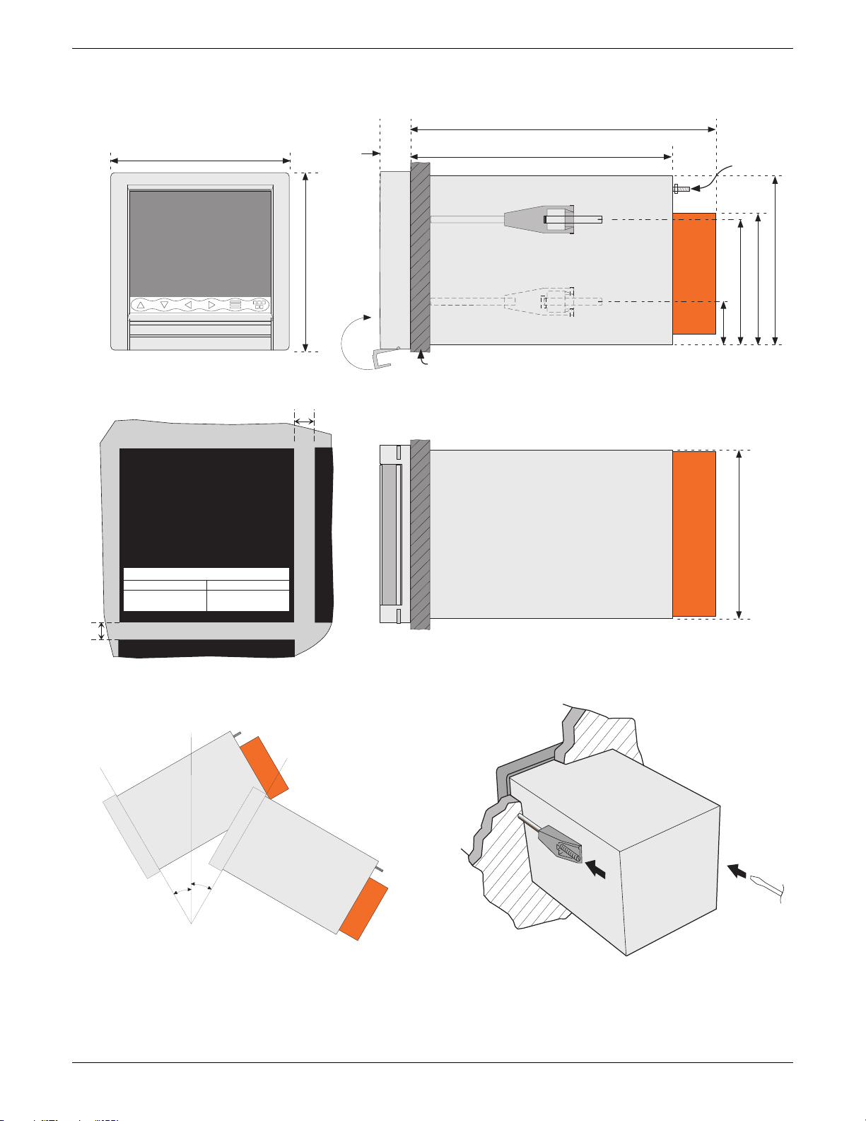
2 INSTALLATION (Cont.)
144 mm
100/180MM PAPERLESS GRAPHIC RECORDER: USER GUIDE
Standard terminal cover: 246.5 mm
Long terminal cover: 288 (closed); 415mm (open)
24.75
mm
211.5 mm
Safety Earth
Front view
Access Flap
Panel cutout
138mm x 138mm (+1 - 0)
5.44 x 5.44 inches
(+0.04 - 0.00)
Minimum recommended inter-unit spacing
Side clamps Top/bottom clamps
x = 15 mm (0.6 inch)
y = 10 mm (0.4 in)
y
or
x = 10 mm (0.4 in)
y = 15 mm (0.6 inch)
144 mm
Panel thickness = 3 to 25 mm. Optimum thickness
depends on panel material
(RHS)
35 mm
Side elevation
137 mm
106.9 mm
102 mm
x
View on underside
137 mm
HA028910
Issue 3 Jun 06
a˚
Panel clamping
Maximum installed angle
a˚ = b˚ = 45 degrees max
Vertical
b˚
Figure 2.1a Mechanical installation details - small frame unit
Page 3
Page 20

2 INSTALLATION (Cont.)
Front view
100/180MM PAPERLESS GRAPHIC RECORDER: USER GUIDE
260.90 mm
292 mm
28.34
mm
211 mm
Safety Earth
Access Flap
Panel cutout
281mm x 281mm (+1 - 0)
or
11.07 x 11.07 inches
(+0.04 - 0.00)
Minimum recommended inter-unit spacing
Side clamps Top/bottom clamps
x = 25 mm (1 inch)
y = 12.5 mm (0.5 in)
y
x = 12.5 mm (0.5 in)
y = 25 mm (1 inch)
292 mm
Side elevation
x
Panel thickness range = 6 to 25 mm.
Optimum thickness depends on panel material
279 mm
216 mm
279 mm
View on underside
Vertical
MAXIMUM INSTALLED ANGLE
a˚ = b˚ = 45 degrees max
b˚
a˚
Panel mounting technique
Figure 2.1b Mechanical installation details -large frame unit
Page 4 HA028910
Issue 3 Jun 06
Page 21
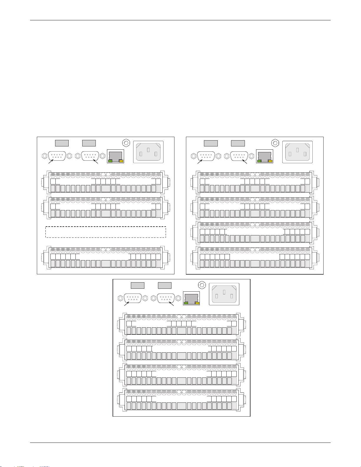
100/180MM PAPERLESS GRAPHIC RECORDER: USER GUIDE
2.2 ELECTRICAL INSTALLATION
2.2.1 Signal wiring
Figures 2.2.1a and 2.2.1b show connector locations for the small and large-frame recorders respectively. The figures
are not to the same scale.
Figure 2.2.1c shows details of universal input board wiring and figure 2.2.1d gives the pinouts for option boards.
CONNECTOR WIRING DETAILS
Maximum wire size = 4.13mm2 (11 AWG)
Minimum wire size = 0.081mm2 (28 AWG)
Design torque = 0.35Nm.
USB 1 USB 2
Serial comms (option)
Port 1
USB Ports (option)
Port 2
Safety Earth
(M4)
Ethernet
RJ45
E
L
Mains (supply)
connection
USB 1 USB 2
USB Ports (option)
N
Serial comms (option)
Port 1
Port 2
Safety Earth
(M4)
Ethernet
RJ45
L
Mains (supply)
connection
E
N
Option slot 1 Option slot 2
Option slot 3 Option slot 4
Input channels 1 to 6
USB 1 USB 2
USB Ports (option)
Serial comms (option)
Port 1
Option slot 1 Option slot 2
Safety Earth
(M4)
Ethernet
Port 2
RJ45
Input channels 13 to 18
Option slot 1 Option slot 2
Option slot 3 Option slot 4
Input channels 7 to 12
Input channels 1 to 6
E
N
L
Mains (supply)
connection
HA028910
Issue 3 Jun 06
Input channels 7 to 12
Input channels 1 to 6
Figure 2.2.1a Connector locations - small frame units
Page 5
Page 22
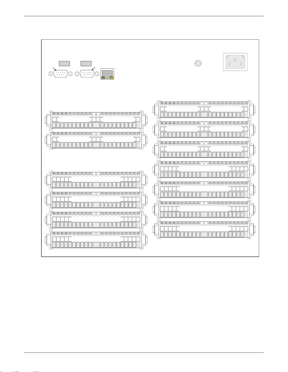
100/180MM PAPERLESS GRAPHIC RECORDER: USER GUIDE
2.2.1 SIGNAL WIRING (Cont.)
USB Ports (option)
Port 1
USB1 USB2
Serial comms (option)
Option board 1 Option board 2
Option board 3 Option board 4
Port 2
Ethernet
RJ45
E
L
Safety Earth
(M4)
Mains (supply)
connection
Option board 5 Option board 6
Option board 7 Option board 8
N
Input channels 37 to 42
Input channels 25 to 30
Input channels 13 to 18
Input channels 1 to 6
Figure 2.2.1b Connector locations - large frame units
Not used Option board 9
Input channels 1 to 7
Input channels 43 to 48
Input channels 1 to 7
Input channels 31 to 36
Input channels 1 to 7
Input channels 19 to 24
Input channels 1 to 7
Input channels 7 to 12
Page 6 HA028910
Issue 3 Jun 06
Page 23
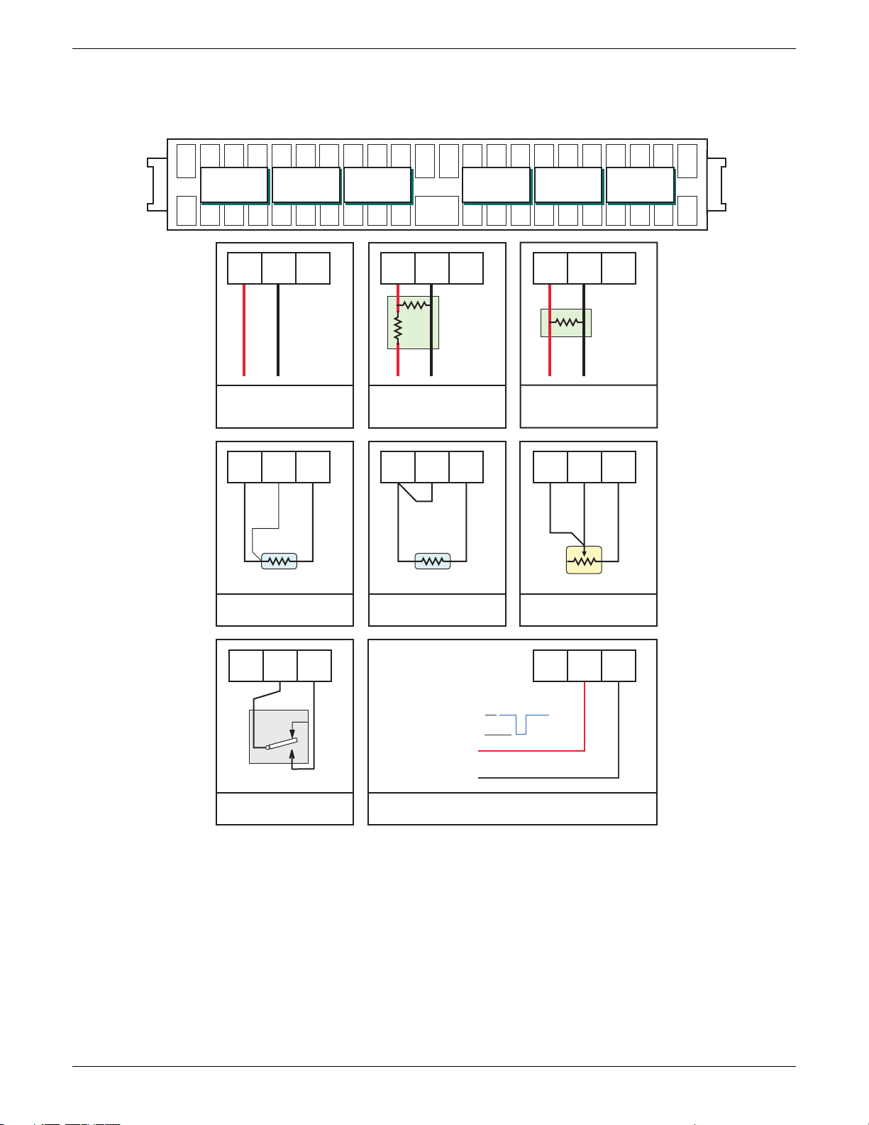
100/180MM PAPERLESS GRAPHIC RECORDER: USER GUIDE
2.2.1 SIGNAL WIRING (Cont.)
1 2 3 4 5 6 7 8 910111213141516171819202122
Channels
1, 7, 13, 19, 25,
31, 37, 43
V+ V- I V+ V- I V+ V- I
2, 8, 14, 20, 26,
Channels
32, 38, 44
Input board pinouts
Channels
3, 9, 15, 21, 27,
33, 39, 45
Cold
junction
Channels
4, 10, 16, 22, 28,
34, 40, 46
Channels
5, 11, 17, 23, 29,
35, 41, 47
Channels
6, 12, 18, 24, 30,
36, 42, 48
V+ V - I V+ V- I V+ V - I
V+ V- I
+
-
-20 to + 20 V dc
Thermocouples
dc millivolts
V+ V- I
RTD
3-wire resistance
thermometer
V+ V- I
V+ V- I
Attenuator
assembly
+
-
-200 to + 200 V dc
V+ V- I
RTD
2-wire resistance
thermometer
-30V < Vin < +0.8V = active
+2V < Vin < 30V = not active
+0.8 < Vin < 2V = not defined
V+ V- I
Shunt
assembly
+
-
DC milliamps
V+ V- I
Potentiometer
Potentiometer
V+ V- I
HA028910
Issue 3 Jun 06
nc
com
no
Minimum contact = 60m sec
Digital input (contact closure)
(Not channels 1, 7, 13 etc)
Figure 2.2.1c Analogue Input board wiring
Not active (2 to 30 V)
Active (0.8 to -30 V)
Vin
User 0V
Digital inputs (voltage levels)
(Not channels 1, 7, 13 etc)
Page 7
Page 24
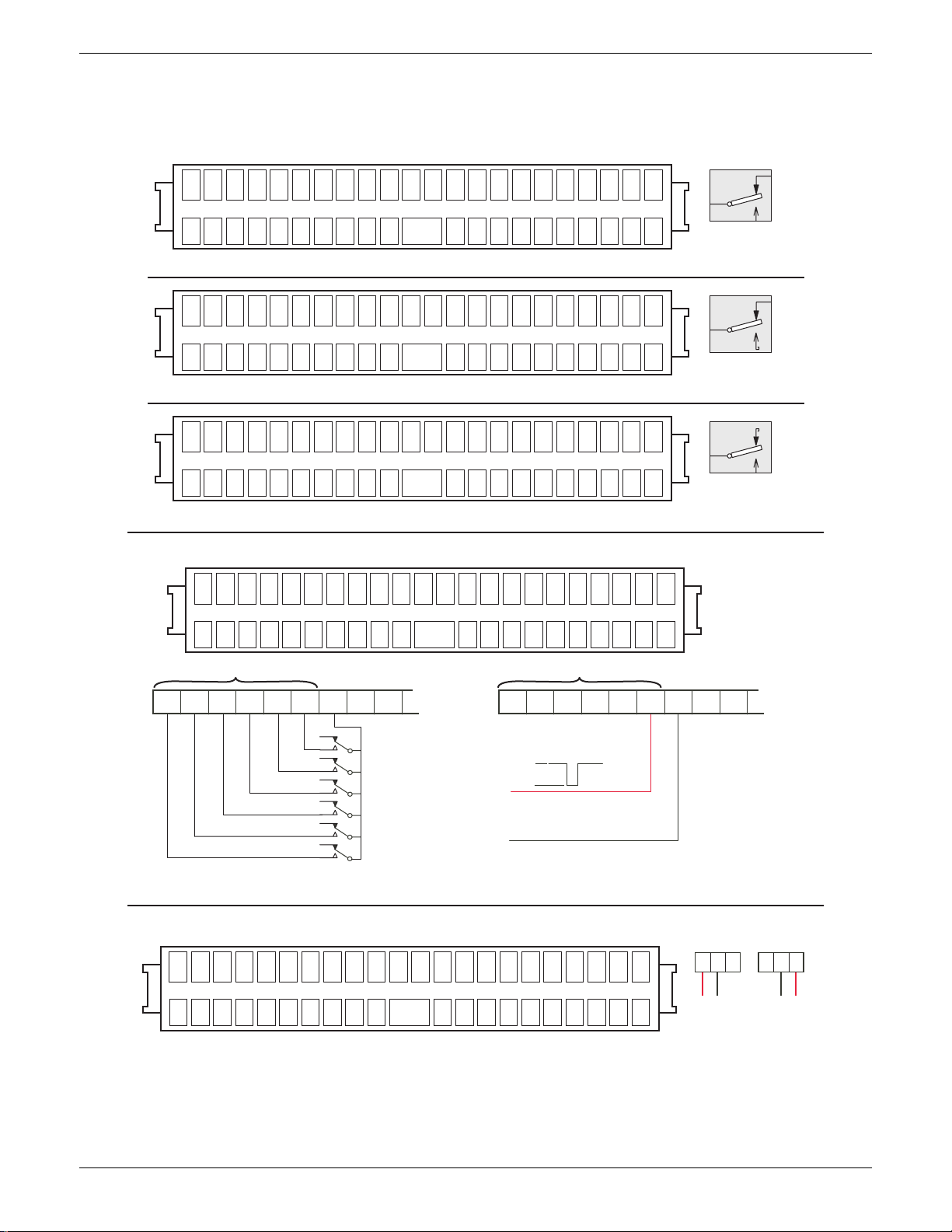
100/180MM PAPERLESS GRAPHIC RECORDER: USER GUIDE
2.2.1 SIGNAL WIRING (Cont.)
Max number of boards = 4 for small frame or 9 for large frame
1 2 3 4 5 6 7 8 910111213141516171819202122
Relay 1
nc c no
Relay 2
nc c no
Relay outputs
Relay 3
nc c no
Three changeover relays
Relay 1
nc c no
Relay 2
nc c no
Relay 3
nc c no
nc
c
no
Contacts shown in
power off/alarm state
1 2 3 4 5 6 7 8 910111213141516171819202122
Rly 1
Rly 2
cc
nc c
Rly 3
nc c ncnc
Rly 4
Rly 1
Rly 2
cc
nc c
Rly 3
nc c ncnc
Rly 4
Four normally closed relays
1 2 3 4 5 6 7 8 910111213141516171819202122
Rly 1
Rly 2
cc
no c
Rly 3
no c nono
Rly 4
Rly 1
Rly 2
cc
no c
Rly 3
no c nono
Rly 4
Four normally open relays
Event inputs (max 4 option boards)
1 2 3 4 5 6 7 8 910111213141516171819202122
123456C 123456C
Event input Number
C123456
+2 to +30 V
+0.8 to -30 V
Event input Number
Behaviour undefined for
+0.8 < Vin < +2 V
c
Contacts shown in
power off/alarm state
c
no
Contacts shown in
power off/alarm state
C123456
Input 6 shown;
inputs 1 to 5 identical
nc
User 0V
Voltage inputsContact closure inputs
Analogue outputs (max 4 option boards)
1 2 3 4 5 6 7 8 910111213141516171819202122
V+ – I+ V+ – I+ V+ – I+ V+ – I+
Channel1Channel
2
Figure 2.2.1d Option wiring sheet 1
Channel1Channel
2
I+
V+ –
+-
Voltage
outputs
V+ –
Current
outputs
I+
+-
Page 8 HA028910
Issue 3 Jun 06
Page 25

100/180MM PAPERLESS GRAPHIC RECORDER: USER GUIDE
2.2.1 SIGNAL WIRING (Cont.)
EIA232C
Pin
Signal
1
NC
2
Rx
3
Tx
4
DTR
5
Signal ground
6
NC
7
NC
8
NC
9
5V via 1500Ω
Figure 2.2.1d (Cont.) Option wiring sheet 2 (Serial communications)
2.2.2 Supply voltage wiring
1
6
5
9
View on solder-bucket face
of user socket
EIA485 (5-wire)
Pin
Signal
1
RxA
2
NC
3
NC
4
NC
5
Signal ground
6
RxB
7
TxA
8
TxB
9
5V via 1500Ω
EIA485 (3-wire)
Pin
Signal
1
Link to pin 7
2
NC
3
NC
4
NC
5
Signal ground
6
Link to pin 8
7
TxA/RxA
8
TxB/RxB
9
5V via 1500Ω
WARNING
DC supply voltages must never be applied to recorders fitted with isolated transmitter power supplies.
Note: The minimum recommended wire size is 20AWG equivalent to 16/0.2 (0.5mm2).
LINE SUPPLY
The supply voltage to the recorder is terminated using an IEC socket which is connected to the mating plug at the rear
of the recorder. The recorder is suitable for use with all ac voltages between 85 and 265 V RMS (47 to 63 Hz), and
requires 60 VA max. power. For recorders without transmitter power supplies, supply voltages between 110V dc and
370V dc are also suitable.
LOW VOLTAGE SUPPLY OPTION
Not suitable for recorders fitted with the isolated transmitter power supply option.
The low voltage supply option is terminated at a three-pin connector (plug mounted on recorder - socket on supply
cable) as shown in figure 2.2.2. The option allows the use of ac or dc supplies with the following characteristics:
AC: 20 to 42V RMS (45 to 400 Hz)
DC: 20 to 54V (See warning above)
Power: 60VA max.
+V or ac
Earth
0V or ac
HA028910
Issue 3 Jun 06
Figure 2.2.2 Low voltage supply pinout (view on fixed connector face)
Page 9
Page 26
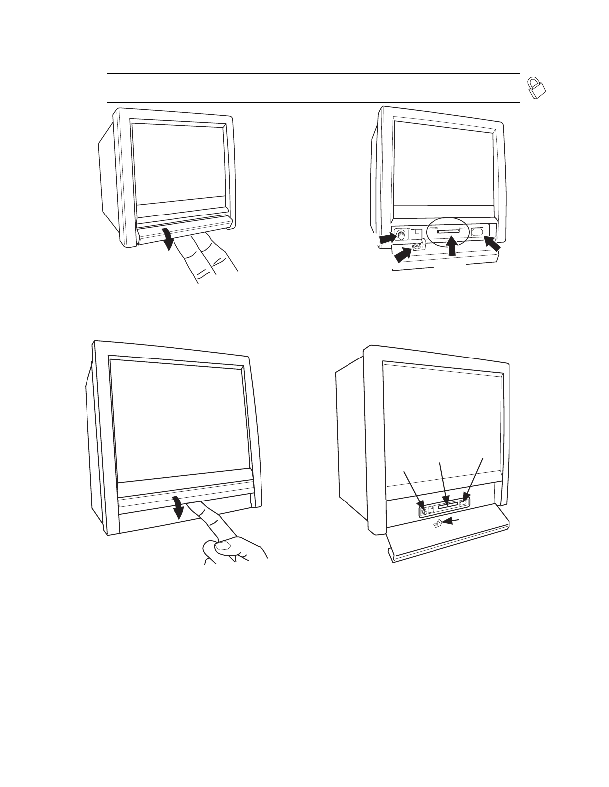
2.3 ACCESS FLAP
Note: See also section 2.4 if the lockable flap option is fitted. Lockable flaps are identified by means
of a padlock symbol printed towards the right hand end of the flap label.
100/180MM PAPERLESS GRAPHIC RECORDER: USER GUIDE
Stylus storage
Door lock (option)
Compact Flash
USBFront
SD or
card
a) Insert finger(s) and pull forward and down (small frame)
c) Insert finger(s) and pull forward and down (large frame)
b) behind flap details (small frame)
SD or
Compact
Stylus
storage
d) behind flap details (large frame)
Flash card
USB
Front
Door lock
(option)
Figure 2.3 Access flap detail
The access flap is located immediately below the recorder screen. To open the flap, insert one or more fingers under
the flap handle, and pull it outwards and down (figure 2.3). A lockable version of the flap is available - see section 2.4
for details. Located behind the flap are (from left to right):
1. a stylus (press to eject)
2. a slot for a Compact Flash or Secure Digital (SD) card
3. a USB port (usbfront).
Page 10 HA028910
Issue 3 Jun 06
Page 27

100/180MM PAPERLESS GRAPHIC RECORDER: USER GUIDE
2.3.1 Stylus
A stylus suitable for use on the touch screen is located in a storage area to the left of the Compact Flash/SD Card slot.
2.3.2 Card slot
The slot for the Compact Flash or SD card is located centrally behind the flap. If an SD card is already fitted, it is
removed by pressing on the card, to unlatch it, then pulling the card out of the slot. If a Compact Flash card is already
fitted, it is removed by a double operation of the eject button. See details in figures 2.3.2a and 2.3.2b, below
Caution
Removal of the memory device whilst archiving is in progress causes irreparable damage to the filing structure
on the device, rendering it unusable. For this reason, archiving should be suspended (section 4.1) (wait for the
green section of the disk icon (section 3.1.3) to go ‘white’) before the device is removed. It is strongly recommended that the 'Remove Media' facility described in section 3.1.4 (Summary menu) be used to ensure that it is
safe to remove the memory device. For recorders fitted with a lockable flap, see also section 2.4.
SD card
(Push in - Push out)
Figure 2.3.2a SD card details
LED INDICATORS
Three LED indicators are located above the card slot as shown in figure 2.3.2c, below.
Card activity
LED (yellow)
Power/watchdog
LED (green)
Figure 2.3.2c indicating LEDs (SD card - Compact Flash card similar)
Eject button
(Press twice)
Figure 2.3.2b Compact Flash card details
USBFront
Power LED (yellow)
Card slot
Compact
Flash card
2.3.3 USB Front Port
A type-A USB socket is located to the right of the Compact Flash/SD Card slot. This port can be used to connect a
mouse, a keyboard, a barcode scanner, a 'memory stick' or a floppy disk drive. If more than one such device is required
at a time, two further, rear panel USB ports (USB 1 and USB 2) are available as an option. Maximum current per USB
device = 500 mA; maximum cumulative current = 1100 mA.
Note: It is the responsibility of the user to establish the electromagnetic susceptibility of any USB peripheral
connected to the recorder. Refer to the USB port specification in Annex A for details.
HA028910
Issue 3 Jun 06
Page 11
Page 28
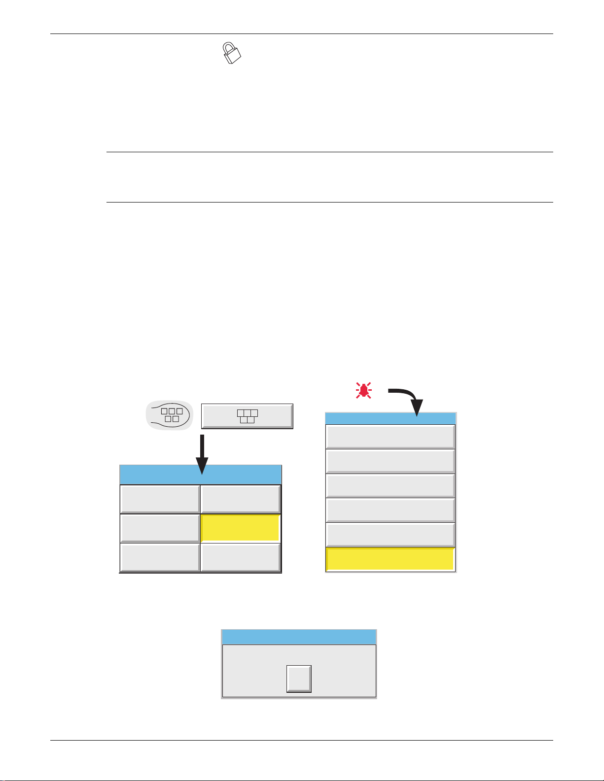
100/180MM PAPERLESS GRAPHIC RECORDER: USER GUIDE
2.4 LOCKABLE FLAP OPTION
This option allows the access flap below the display screen to be locked against unauthorized access to the Compact
Flash/SD card. It also provides some protection (in the form of a warning message) against the inadvertent removal of
such a card whilst archive data is being written to it. Removal of the memory device whilst it is being written to will
not only corrupt the current archive, but might also damage the memory device irreparably, rendering it unusable. See
also section 3.1.4.
Notes:
1. Control of the flap lock is available only to users with ‘Archiving Control’ permission enabled.
2. Control of the flap lock is not possible via Bridge software.
3. The description below applies only to Archive data.
2.4.1 Flap lock operation
ARCHIVE INACTIVE
1. Touch the root menu or alarm status area at the top of the screen.
2. Touch the ‘Unlock Flap’ key (figure 2.4.1a).
3. Archiving is suspended, the internal solenoid releases the catch, to allow the flap to be opened, and a pop-up message appears ‘OK to remove archive media’ (figure 2.4.1b).
4. After approximately five seconds, the solenoid returns the catch to the locked position. The flap can be returned to
the closed position whether or not the flap lock is engaged. It is up to the user to ensure that the flap is properly
closed and locked.
Touch Root menu key or Alarm area
(e.g. channel alarm symbol)
Root Menu
Home Operator
File
Unlock Flap
Goto View Goto Group
Figure 2.4.1a Unlock Flap key locations
Archive Media
OK to remove archive media
Summary
Instrument Alarm Summary
Ack all Alarms
Alarm Summary
Batch Summary
Message Log
Unlock Flap
Ok
Figure 2.4.1b ‘OK to remove archive media’ message
Page 12 HA028910
Issue 3 Jun 06
Page 29

100/180MM PAPERLESS GRAPHIC RECORDER: USER GUIDE
2.4.1 FLAP LOCK OPERATION (Cont.)
ARCHIVE ACTIVE
1. Touch the root menu key or alarm status area at the top of the screen.
2. Touch the ‘Unlock Flap’ key (figure 2.4.1a).
3. The flap unlocks for 5 seconds in the normal way (to allow access to the stylus and the usbfront port), but a warning message appears on the screen (figure 2.4.1c).
a) If the ‘Cancel’ key is operated, the message disappears. Subsequently, if this is a Demand Archive the ‘De-
mand archive finished’ message appears when the archive is complete. Archiving is not suspended, so operate
the ‘Suspend Archiving’ key before removing the memory device. This ensures that no attempt will be made
by the recorder to write to the device until ‘Resume Archiving’ is operated.
b) If the ‘Cancel’ key is not operated (the warning message remains on the screen), then when the archive is com-
plete, archiving is automatically suspended and the flap unlocks again for five seconds, allowing the memory
device to be removed. The message on the screen changes to ‘OK to remove archive media’ (figure 2.4.1b),
although, for demand archives this is masked by the ‘Demand archive finished’ message.
DO NOT REMOVE Archive Media!
Will advise when OK to remove...
Cancel
Figure 2.4.1c ‘Do Not Remove Archive Media’ message
4. Archiving automatically resumes:
a. 15 seconds (max.) after a memory device is inserted.
b. after 10 minutes if no new memory device is inserted (i.e. the flap was opened for a reason other than to re-
place the memory device).
Note A System message is generated each time the flap is unlocked.
HA028910
Issue 3 Jun 06
Page 13
Page 30
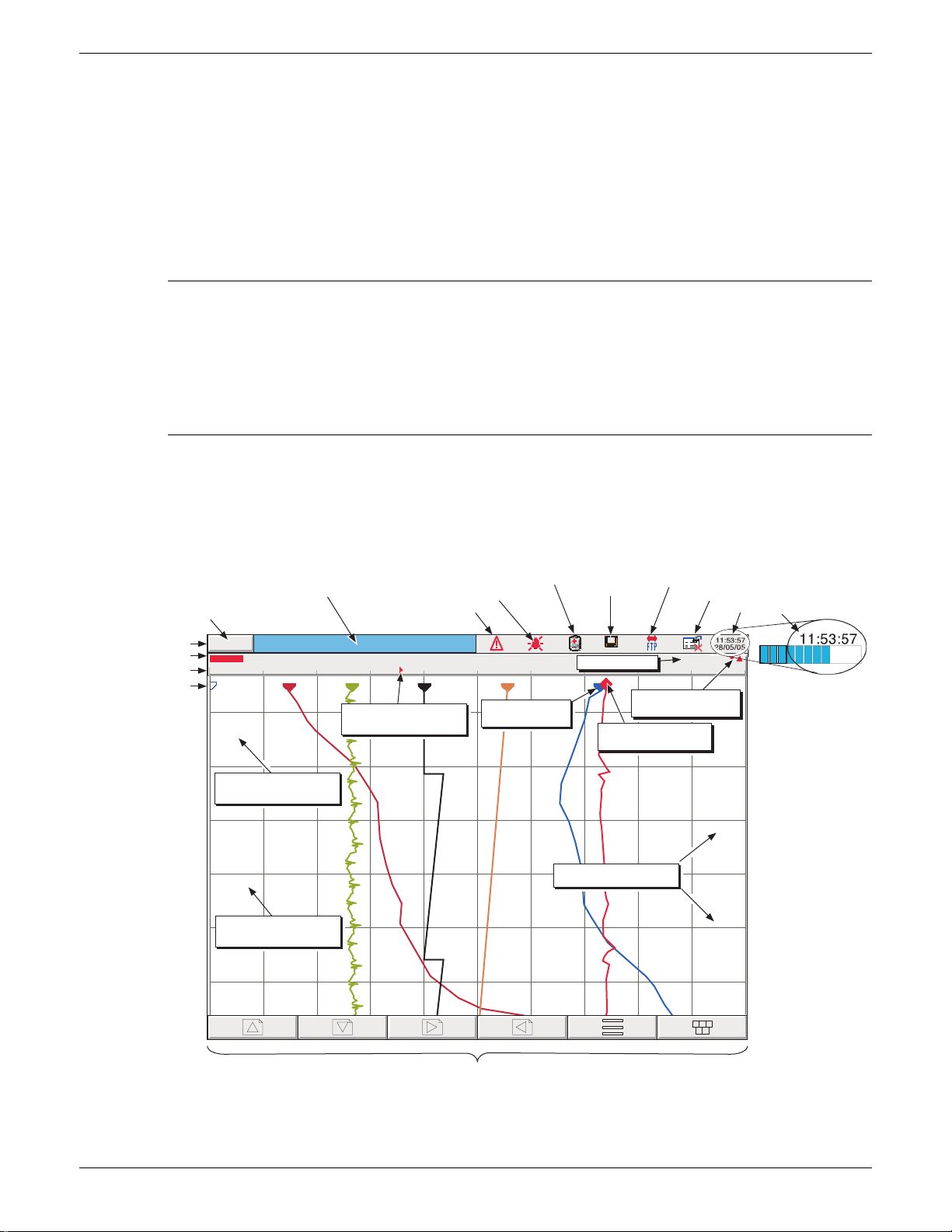
100/180MM PAPERLESS GRAPHIC RECORDER: USER GUIDE
g
3 PROCESS VARIABLE DISPLAY
The operator interface consists of a touch-sensitive screen, showing either process variable values in one of a number
of formats, or, showing configuration or operational details for use in setting up the recorder. This section (3) describes
the process variable displays. Section 4 describes the Configuration displays.
Figure 3, below, depicts a typical trend display for a large-frame unit and gives details of the various areas of the display page. The small frame display is similar, but the navigation keys are printed on a strip below the chart area instead
of being drawn on the screen.
Notes:
1. Dialogue boxes, message boxes etc. cause Process Variable displays to 'freeze' for as long as the box is on
display. Root and Option menus (amongst others) time-out (i.e. are removed from the display) after approximately one minute. Messages, however, are displayed until the operator takes action to remove them.
It should be noted, especially, that several message boxes may be active at one time, but only the oldest
one is visible, until it is removed to reveal the 'next oldest' message, and so on.
2. Many of the screen components can be customised as to colour/size etc. as described in section 4.6.10
(Customise).
TRUNCATION OF NUMERIC VALUES
If the amount of space on the display page is insufficient to display the full width of the process variable or scale value,
then the displayed value is rounded down and the number of decimal places reduced. If the width is still too restricted,
the value is displayed in 'scientific' format, or if this is still too wide, the final visible character of the integer part of the
value is replaced by a '?' (as depicted in figure 3.4.4b)
Page Name and batch status
Current access level or
Channel descriptor
user name
Status bar
Channel scale
Off channel(s)
(if option fitted)
Logged out
Channel 1
0.00
28/05/05 11:51:33 Alarms(s) off 3(1)
Channel 3 alarm 1 off
time and date
28/05/05 11:47:51 Alarms(s) on 3(1)
Channel 3 alarm 1 on
time and date
No Batch in Progress
Channel alarm
Instrument alarm
Group name
Alarm threshold marker
(absolute high)
Change battery alarm
Other traces
(Pen icon)
Disk icon
(% free space)
99%
Channel value
Current trace alarm
Scale (Current) trace
(Diamond icon)
Time/date stamp
FTP activity indicator
Configuration locked indicator
Time and date
73.98V
100.0020.00 60.00 80.0040.00
An animated bar appears
icons
over the date, when the
11:52:04
recorder is busy.
28/01/04
Though normally pale
blue, the bar is goldcoloured when the
recorder configuration is
11:50:44
being updated remotely
28/05/05
via Bridge software.
11:49:24
28/05/05
11:48:04
28/05/05
11:46:44
28/05/05
11:45:24
28/05/05
Navi
ation keys
Figure 3 Trend display definitions (large frame unit)
Page 14 HA028910
Issue 3 Jun 06
Page 31

100/180MM PAPERLESS GRAPHIC RECORDER: USER GUIDE
3 PROCESS VARIABLE DISPLAY (Cont.)
CURRENT TRACE ALARM ICONS
In each of the different types of PV display, each channel's faceplate gives the status of the channel's alarms. The status
of each alarm is shown by one of the icons depicted in table 3, either flashing (if it is active and unacknowledged) or on
continuously (if it is active and acknowledged). (See section 3.1.4, below, for a description of how to acknowledge
alarms.) Absolute alarm threshold icons and deviation alarm bars appear in any display which includes a scale (except
circular charts). For deviation alarms the bar stretches from (Reference - Deviation) to (Reference + Deviation).
Note: 'Trigger' alarms do not display threshold marks or bars, or faceplate symbols.
Absolute High
Absolute Low
Deviation in
Deviation out
Rate-of-change Rising
Rate-of-change Falling
Horizontal
scales
Vertical
scales
For Deviation alarms, R = Reference; d = deviation
Absolute
low
Absolute
high
Deviation
In / Out
R
d d
dd
R
Rate of
change
No
indication
No
indication
Faceplate symbols Scale symbols
Table 3 Alarm icons
3.1 STATUS BAR
This appears across the top of the display, and contains the items described below.
3.1.1 Current access level
There are four access levels available (Logged out, Operator, Engineer and Service), and the current level is displayed
in this key at the top left hand corner of the display. Touching this key calls the login page as described in section 3.3.1
(Access to configuration) below. If a user has been added (using the 'Add User' part of the Security setup - section
4.4.3, below), then the 'Full User Name' is displayed instead of the access level.
3.1.2 Page name
Initially this shows the current group's descriptor. The name changes according to context for example 'Operator' or
'Config-Archive' If the Batch option is fitted, this area contains batch information as well as the page name. Touching
the area calls the Batch Status page. See section 4.3.10 for further Batch details.
HA028910
Issue 3 Jun 06
Page 15
Page 32

100/180MM PAPERLESS GRAPHIC RECORDER: USER GUIDE
3.1.3 Alarm indication
This area of the display can contain a number of status icons: Instrument alarm, Channel alarm, Battery change, Disk
status, FTP in progress, Configuration locked, and so on. Pressing this area of the screen calls the 'Summary menu' -
(section 3.1.4) allowing the user to view active instrument alarms, to acknowledge all channel alarms, to display the
Alarm Summary or Message Log page. Media removal strategy is also controlled from this pop-up. If the access flap
'Lock' option is fitted, see also section 2.4.
For channel alarm symbols refer to 'Current Trace Alarm Icons', above.
INSTRUMENT ALARM
This indicator appears, flashing, if any of the following errors are active. The instrument alarm summary page, described in Section 3.1.4, allows the user to view such instrument alarms as are active.
Archive failed -(message) Message explains archive failure.
Battery-backed RAM cleared This message appears if the battery has failed, and the unit has been switched off.
Clock failure Internal clock was corrupt at power up, or the time has never been set. Can be
caused by battery failure, in which case the battery icon will also be visible. The
error is cleared by setting the time and date. Server time forced to 00:00 1/1/1900.
Channel error Indicates a hardware failure in the channel circuit or in the internal CJ temperature
measurement
Channel failure Indicates a hardware failure in the input channel circuit (see note).
DHCP Server failure For instruments with IP address lookup set to ‘Get from DHCP Server ’, this alarm
occurs if the recorder cannot obtain an IP address from the server. See section 4.5
for details.
FTP Archiving file lost Archive failed. A file which has not been archived, has been detected.
FTP Archiving too slow Remote archive is too infrequent. The recorder effectively switches to 'Automatic'
(section 4.3.5) to ensure that data is not lost.
FTP Primary Server Failure This error is set if the recorder fails, after two attempts, to establish communica-
tions with the primary server as defined in Archive Configuration (section 4.3.5).
After the second attempt has failed, the Secondary server is tried.
FTP Secondary Server Failure This error is set if the recorder fails, after two attempts, to establish communica-
tions with the secondary server as defined in Archive Configuration (section 4.3.5).
See also 'FTP Primary Server Failure, above.
Insufficient non-volatile memory... There is insufficient memory available for the configuration. Can be caused by use
of Rolling Average maths functions.
Internal flash: \
Internal flash: \history\ required repair Error found in the internal file system at power-up, and corrected.
Internal flash: \screens\ required repair Error found in the internal file system at power-up, and corrected.
Internal flash: \user\ required repair Error found in the internal file system at power-up, and corrected.
Internal flash: \user\ is full Appears if the User partition is full. To clear, either user screens must be simplified
Maths Channel failure Appears if, for example, the divisor of a divide function is zero.
Media Archiving file lost Archive failed. A file which has not been archived, has been detected.
Media Archiving too slow Archive is too infrequent. The recorder effectively switches to 'Automatic' (section
Network boot failure The recorder is unable to establish connection with the BootP or DHCP server. This
Output channel failure Indicates a hardware failure in the output channel circuit (see note).
application\ required repair
Note: Unlike other instrument alarms, Channel Failure and Output channel failure are not self clearing. Once
the cause of the failure is rectified, the recorder must be power cycled in order to clear the alarm.
Error found in the internal file system at power-up, and corrected.
or files must be deleted from \User\, or both.
4.3.5) to ensure that data is not lost.
might be caused by, for example, cable failure, network hardware failure, etc.
Page 16 HA028910
Issue 3 Jun 06
Page 33

100/180MM PAPERLESS GRAPHIC RECORDER: USER GUIDE
3.1.3 ALARM INDICATION (INSTRUMENT ALARMS) (Cont.)
Paper Low/Paper Out Warning messages from the ASCII printer (if fitted).
Printer not responding There is a fault in the serial comms link with the ASCII printer (if fitted).
Recording failure - (message) Message explains recording failure - due to file error, internal overflow etc.
Removable media failure This error is set if the archive storage device is corrupt, wrongly formatted etc.
Becomes active only when an Archive is attempted.
Removable media full Archive storage device full. Becomes active only when an Archive is in progress.
SNTP server failure This error is set if:-
a) the year received from the server is < 2001 or > 2035 or
b) the configured SNTP server cannot be accessed.
Time synchronisation failure Set if 5 or more 'Time change events' are caused by the SNTP server within 24 hrs.
A 'Time change event' occurs whenever the recorder time is found to be more than
2 seconds different from the server time. The alarm does not appear until 24 hours
have elapsed since the first of the five or more Time Change events occurred.
USB over current USB power fault - too much current being drawn by a USB device (max 500 mA).
USB power fault key USB power fault - too much current being drawn by all USB devices (max 1100
mA)
USB unsupported Unsupported USB device inserted.
HA028910
Issue 3 Jun 06
Page 17
Page 34

100/180MM PAPERLESS GRAPHIC RECORDER: USER GUIDE
3.1.3 ALARM INDICATION (Cont.)
CHANNEL ALARM
This red 'bell' indicator appears if any channel is in alarm. The symbol is illuminated continuously if all alarms are
acknowledged or flashes if any active alarm is unacknowledged. Refer to 'ALARM ACKNOWLEDGEMENT' below,
for details of how to acknowledge alarms.
CHANGE BATTERY
This flashing indicator first appears when the battery voltage (checked every 15 minutes) indicates that the battery is
approaching the end of its useful life. The indicator continues to flash until the battery is replaced (B2.2 in Annex B).
The indicator does not appear if the battery is not fitted.
DISK ICON
This shows the free space available on whatever mass storage medium is fitted (if any), and selected for Archive destination (note 1). The disk icon appears soon after the device is inserted (but see note 2). During archiving, the colour of
the central area of the disk changes to green (see note 3). No other disk activity (e.g. save/restore configuration) is
indicated.
This area of the icon coloured
green during any archive activity
(not necessarily to the device
selected in Archive configuration).
99%
Figure 3.1.3 Archive activity indication
Notes
1. The icon appears only when a memory device is present, AND when that memory device has been selected in the 'Archive to media' selection in archive configuration (section 4.3.5). For example: if a
memory stick is inserted in ‘usbfront’, but Archive to Media is set to 'mediacard', then the disk icon appears only if a suitable card is present in the 'mediacard' slot.
2. When a disk is inserted into a USB floppy disk drive which is connected to the recorder, the disk icon
appears only after the disk has been accessed, (either by reading from it or writing to it), or after the file
system has been opened by touching the ‘file’ key. (This note does not apply for disks which have been
inserted before the disk drive is plugged in.)
3. The central area goes green whenever local archiving is taking place - not only when archiving is taking
place to the memory device selected in Archive configuration.
FTP ICON
The FTP icon appears to the right of the disc icon position whenever transfer activity is taking place.
CONFIGURATION LOCKED INDICATOR
This symbol appears only when Bridge software is being used, in the following situations:
1. Whilst units are 'synchronising' configuration changes
2. Whilst configuration is taking place. If the reconfiguration is taking place at the host pc (Bridge 'Full' only), then
the symbol appears at the target instrument, and vice-versa.
TRIAL MODE INDICATOR
This symbol is displayed whilst the recorder Trial Mode (section 4.3.21) is enabled.
Page 18 HA028910
Issue 3 Jun 06
Page 35

100/180MM PAPERLESS GRAPHIC RECORDER: USER GUIDE
Touch Alarm area
(e.g. channel alarm symbol)
Ack all Alarms
Alarm Summary
Batch Summary
Message Log
Remove Media
Instrument Alarm Summary
Summary
3.1.4 Summary menu
This pop-up display appears if the Alarm Indication area at the top of the display is touched. Figure 3.1.4 shows the
display.
Note: For recorders fitted with the Lockable
Flap option, 'Remove Media' is replaced by
'Unlock Flap' - see section 2.4, above
Figure 3.1.4a Summary pop-up menu
INSTRUMENT ALARM SUMMARY
This contains a list of the currently active instrument alarms. For a list of possible alarms and their definitions, see
section 3.1.3, above.
ACK ALL ALARMS
'Yes' confirms all active, unconfirmed alarms.
This page can also be displayed by touching an alarm in the alarm summary page, described below.
Figure 3.1.4b Typical Instrument alarm summary display
Instrument Alarm Summary
Maths Channel Failure
Printer Error
Ok
Ack all Alarms
Confirm acknowledge of alarms?
Yes No
Figure 3.1.4c Ack all Alarms display
HA028910
Issue 3 Jun 06
Page 19
Page 36

100/180MM PAPERLESS GRAPHIC RECORDER: USER GUIDE
3.1.4 SUMMARY MENU (Cont.)
ALARM SUMMARY PAGE
As shown in figure 3.1.4d, below, the alarm summary page contains the following information for the current group:
1. Alarm identifier. This appears as a point ID, followed by the relevant alarm number in parentheses. For example,
Alarm 1 on maths channel 6 would appear as: D6 (1). Maths channels are prefixed by 'D'. Totalisers are prefixed
by 'T' and Counters are prefixed by 'C'. Input channels are not prefixed.
2 Alarm threshold for absolute alarms only
3 The current process value for the point
4 An alarm symbol (see Table 3). Alarm symbols flash until acknowledged.
Notes:
1. Alarms are always listed in Point/Alarm order with input channels first, followed by derived channels,
totalisers and counters, if these options are fitted.
2 When the alarm source returns to its non-alarm state: Unlatched alarms are removed from the list whether
or not they have been acknowledged; latched alarms remain displayed until acknowledged. See section
4.3.3 for a description of alarm types and actions.
3. There are no time or history components associated with the Alarm Summary. If Alarm messages have
been enabled in the relevant group's configuration (section 4.3.2), then alarm initiation/acknowledgement
times and dates can be found from the trend and trend history displays, described in section 3.4 or in Message log described later in this section.
4. If an alarm is active on a channel which is not included in any group, then although the channel alarm
symbol will flash, the alarm will not appear in any of the alarm summary pages.
Touch Alarm area
(e.g. channel alarm symbol)
Summary
Instrument Alarm Summary
Ack all Alarms
Alarm Summary
Batch Summary
Message Log
Unlock Flap
Alarm Summary: Group 5
1(1) Water temp 1a 60.0000 C 68.5277
2 (1) Water temp 1b 30.0000 C 23.4531
2 (2) Water temp 1b 10.0000 C 23.4531
3 (1) 0il pressure 250.000 PSI 260.3425
4(1) Transfer 15.3678
Alarm setpoint
(Absolute alarms only)
Ack Alarm
Confirm acknowledge of alarm?
Channel no.
(alarm no.)
Channel
descriptor
Yes No
Touch alarm to
call 'Acknowledge'
dialogue box.
Current process
Goto Group
Group 1
Group 3
Group 5
value
Group 2
Group 4
Group 6
Alarm type
symbol
Figure 3.1.4d Alarm Summary display
Page 20 HA028910
Issue 3 Jun 06
Page 37

100/180MM PAPERLESS GRAPHIC RECORDER: USER GUIDE
3.1.4 SUMMARY MENU (Cont.)
ALARM ACKNOWLEDGEMENT
Alarms can be acknowledged individually, on a group basis, or globally (all alarms).
INDIVIDUAL ALARMS
Individual alarms are acknowledged from the alarm summary page by touching the relevant item (highlights yellow),
then touching 'Yes' in the resulting pop-up confirmation box. Figure 3.1.3a, above, attempts to show this process.
GROUP ALARMS
Alarms can be acknowledged on a group basis by calling the alarm summary page for the relevant group, then pressing
the Options key (section 3.2), the 'Ack Group Alarms' key and finally, 'Yes' in the resulting pop-up confirmation box.
Figure 3.1.4e below, attempts to show this process.
Alarm Summary: Group 1
1(1) Water temp 1a 60.0000 C 68.5277
2 (1) Water temp 1b 30.0000 C 23.4531
2 (2) Water temp 1b 10.0000 C 23.4531
3 (1) 0il pressure 250.000 PSI 260.3425
4(1) Transfer 15.3678
Option Menu
Batch
Note
Ack Group Alarms
Figure 3.1.4e Group Alarm acknowledgement
ALL ALARMS
To acknowledge all active alarms, touch (e.g.) the channel alarm icon at the top of the screen. From the resulting 'Sum-
mary’ menu, select 'Ack all Alarms', then finally, touch 'Yes' in the resulting pop-up confirmation box.
Note: The options menu is context sensitive, and may, therefore, not appear as illustrated above.
Ack Group Alarms
Confirm acknowledge of alarms?
Yes No
HA028910
Issue 3 Jun 06
Page 21
Page 38

100/180MM PAPERLESS GRAPHIC RECORDER: USER GUIDE
3.1.4 SUMMARY MENU (Cont.)
BATCH SUMMARY
If the Batch option is fitted (section 4.3.10) a ‘Batch Summary’ key appears in the Summary menu.
Note: The following description shows the situation where batch ‘Scope’ is configured as ‘Group’. The
description is similar when ‘Scope’ = ‘Instrument’ except that there is only one line (Instrument), instead of one
line per group.
As shown in figure 3.1.4f, below, the Batch Summary page contains the following batch information:
1. Group names in group number order (if Scope = Group) or Instrument Name if scope = ‘Instrument’
2. Batch active indicator (green spot)
3. Initiation time and date
4. Elapsed time for the batch
4. Batch Field 1 and its ‘value’.
Summary
Instrument Alarm Summary
Ack all Alarms
Touch Alarm area
(e.g. channel alarm symbol)
Alarm Summary
Batch Summary
Message Log
Unlock Flap
Batch Summary - Group Mode
ColourMix1 25/04/06 09:12:18 00:02:41 Batch Number: 060425C1
ColourMix2 25/04/06 08:45:13 00:29:46 Batch Number: 060425M1
ColourMix3 25/04/06 08:50:07 00:24:40 Batch Number: 060425Y1
ColourMix4 25/04/06 09:03:53 00:11:06 Batch Number: 060425K1
Mix1 00:00:00 00:00:00 Mixed batch:
Mix2 24/04/06 23:11:48 09:57:49 Mixed batch: 060424R..
Group 7 00:00:00 00:00:00 Batch field 1
Group 8 00:00:00 00:00:00 Batch field 1
Batch running
Group 9 00:00:00 00:00:00 Batch field 1
indicator
Group 10 00:00:00 00:00:00 Batch field 1
Group 11 00:00:00 00:00:00 Batch field 1
Add Inputs 00:00:00 00:00:00 Batch field 1
Group names
Batch start
time and date
Elapsed
time
Batch Field 1
text
Batch Field 1
values
Click to highlight
Mix2
Full Details
Batch Control
Sort (ON)
Highlight (OFF)
Exit
Figure 3.1.4f Batch Summary page (Group mode - sort OFF; highlighting ON))
Touching anywhere on a group row calls a pop-up menu as shown above. The functions of this menu are as follows:
Page 22 HA028910
Issue 3 Jun 06
Page 39

100/180MM PAPERLESS GRAPHIC RECORDER: USER GUIDE
3.1.4 SUMMARY MENU (Cont.)
BATCH SUMMARY (Cont.)
FULL DETAILS
Touching this key calls the Batch Details page showing the group name, batch status and batch field details.
BATCH CONTROL
This calls a page similar to the Full Details page, but including a ‘NEW’ key to allow the operator to start a new batch.
If the batch is configured as ‘Start/Stop’ a ‘Stop’ key is also included allowing the user to stop the batch.
SORT
If Sort is Off (default), the groups appear in Group number order with Group 1 at the top and group 12 at the bottom.
The key legend is ‘Sort (ON)’.
If Sort is On, those groups with batches running appear (in group number order) at the top of the list, followed by any
remaining groups (also in group number order). The key legend is ‘Sort (OFF)’.
HIGHLIGHT
If Highlight is Off (default), then all groups’ text appears in white. The key legend is ‘Highlight (ON)’.
If Highlight is On then the text associated with groups which have batches running appears in green. Remaining
groups’ text is in white. The key legend is ‘Highlight (OFF)’.
EXIT
Closes the pop-up menu. (It closes itself after approximately 50 seconds.)
HA028910
Issue 3 Jun 06
Page 23
Page 40

100/180MM PAPERLESS GRAPHIC RECORDER: USER GUIDE
3.1.4 SUMMARY MENU (Cont.)
MESSAGE LOG
Note: Message log can also be selected using the Root menu/Goto View/Message log key. This goes immediately to the first Message Log page for the current group to the screen (i.e. the 'Goto Group' menu does not
appear).
If there are more messages than can be displayed in the height of the screen, a scroll bar appears to allow 'hidden' messages to be displayed.
Messages are retrieved from the history files in batches of 100 messages. If there are more than 100 messages, 'Earlier
messages..' appears after the hundredth message. Touching 'Earlier messages..' calls the option menu, and touching
'Earlier messages..' in this menu, calls the next batch of 100, and so on. If applicable, operating 'Later messages..' /
'Later messages..' calls the previously displayed 100 messages.
As can be seen from figure 3.1.4g the list of messages can be 'filtered' both by type and by time. For example, setting
the message type to 'Alarm' and the period filter to 'Last Day' excludes all messages except alarm messages which have
occurred within the previous 24 hours. (For clarity, the figure shows both filters open. In fact, only one can be open at
a time)
Summary
Instrument Alarm Summary
Ack all Alarms
Alarm Summary
Batch Summary
Message Log
Unlock Flap
Touch Alarm area
(e.g. channel alarm symbol)
Goto Group
Group 1
Group 3
Group 2
Group 4
Group 5
Engineer
Message Log: Group name
05/04/05 09:06:18 Alarm(s) on 1(1)
05/04/05 09:06:18 Operator's name: Andrew
05/04/05 09:06:18 Customer: FishesRus
05/04/05 09:06:18 Batch number:020205A12
05/04/05 09:06:18 Config Revision:682759 Security Revision 746261
05/04/05 09:06:18 Batch start (Engineer)
05/04/05 08:50:30 Configuration revision 682,759 was 682,758
05/04/05 08:50:28 Batch) Name files by batch true was false
05/04/05 08:50:28 Batch) On start log 3 was 1
05/04/05 08:50:28 Batch) Field 3 Operator's name: was Batch field 3
05/04/05 08:50:28 Batch) Field 2 Customer: was Batch field 2
05/04/05 08:50:28 Batch) Field 1 Batch number: was Batch field 1
05/04/05 08:50:28 Batch) Batch fields 3 was 1
05/04/05 08:50:50 Config,Signed:Engineer, Authorized:Engineer,New batch fields
04/04/05 16:42:11 Alarm(s) off 2(1)
04/04/05 16:32:50 Alarm(s) off 1(1)
04/04/05 16:31:05 Batch stop (Engineer)
04/04/05 16:31:05 Stop Batch,Signed:Engineer,Authorized:Engineer,Belt Failure
04/04/05 16:29:33 Alarm(s) Ackd 1(1) 2(1)
04/04/05 16:28:05 Ack all alarms,Signed:Engineer,Authorized:Engineer,Belt Failure
04/04/05 16:27:13 Alarm(s) on1(1)
04/04/05 16:27:13 Alarm(s) on2(1)
04/04/05 14:06:22 Config Revision:682759 Security Revision 746261
04/04/05 14:06:22 Batch start (Engineer)
Group 5
Batch number:050405A12
All Messages All History
System
Alarms
Power Up
General
Batches
Logins
Signings
Audit Trail
Reports
All Messages
Last Hour
Last Day
Last 3 Days
Last Week
Last Month
All History
Figure 3.1.4g Message log page showing message-type picklist
Group 6
09:06:22
05/04/05
Page 24 HA028910
Issue 3 Jun 06
Page 41

100/180MM PAPERLESS GRAPHIC RECORDER: USER GUIDE
3.1.4 SUMMARY MENU (Cont.)
MESSAGE LOG (Cont.)
MESSAGE TYPE FILTER
All Messages All messages are displayed
System Only System messages and instrument alarms are listed
Alarms Only alarm on/off and acknowledgement messages appear.
Power Up Displays power up messages only including Config Revision and Security revision are included. See 'About'
(section 4.6.11) for more details.
General Displays e-mails, messages sent via Modbus, operator notes/custom messages etc. if they do not have to be
'signed' (Auditor option 21CFR11 only - see section 4.4 for more details). If the notes etc. are signed, they
appear in the 'Signings' message type list.
Batches Displays only batch messages (including Config and Security Revisions if either Auditor option is enabled).
Logins Lists only changes in login.
Signings This list contains only notes, messages etc. that have been signed (and authorized). This category is used only
when 'Require Signing' (and 'Require Authorization') is (are) enabled in the Security/Management menu- see
section 4.4 for more details.
Audit trail This list contains Configuration change messages only. This category is used only when 'Audit Trail' is ena-
bled - see section 4.4 for more details.
Reports For each report, this contains all the Report's fields (set up in 'Reports' configuration) on separate lines. Line
Feed fields are ignored (i.e. they do not appear).
PERIOD FILTER
This picklist allows the user to select one of the following to define the period of time that the message list is to encompass:
All History, Last Month (28 days), Last Week, Last 3 Days, Last Day or Last Hour.
HA028910
Issue 3 Jun 06
Page 25
Page 42

100/180MM PAPERLESS GRAPHIC RECORDER: USER GUIDE
3.1.4 SUMMARY MENU (Cont.)
MESSAGE LOG (Cont.)
OPTION MENU
Touching a message (highlights yellow) calls the Option Menu* as shown in figure 3.1.4h, below.
Engineer
Message Log: Group name
05/04/05 09:06:18 Alarm(s) on 1(1)
05/04/05 09:06:18 Operator's name: Andrew
05/04/05 09:06:18 Customer: FishesRus
05/04/05 09:06:18 Batch number:020205A12
05/04/05 09:06:18 Config Revision:682759 Security Revision 746261
05/04/05 09:06:18 Batch start (Engineer)
05/04/05 08:50:30 Configuration revision 682,759 was 682,758
05/04/05 08:50:28 Batch) Name files by batch true was false
05/04/05 08:50:28 Batch) On start log 3 was 1
05/04/05 08:50:28 Batch) Field 3 Operator's name: was Batch field 3
05/04/05 08:50:28 Batch) Field 2 Customer: was Batch field 2
05/04/05 08:50:28 Batch) Field 1 Batch number: was Batch field 1
05/04/05 08:50:28 Batch) Batch fields 3 was 1
05/04/05 08:50:50 Config,Signed:Engineer, Authorized:Engineer,New batch fields
04/04/05 16:42:11 Alarm(s) off 2(1)
04/04/05 16:32:50 Alarm(s) off 1(1)
04/04/05 16:31:05 Batch stop (Engineer)
04/04/05 16:31:05 Stop Batch,Signed:Engineer,Authorized:Engineer,Belt Failure
04/04/05 16:29:33 Alarm(s) Ackd 1(1) 2(1)
04/04/05 16:28:05 Ack all alarms,Signed:Engineer,Authorized:Engineer,Belt Failure
04/04/05 16:27:13 Alarm(s) on1(1)
04/04/05 16:27:13 Alarm(s) on2(1)
04/04/05 14:06:22 Config Revision:682759 Security Revision 746261
04/04/05 14:06:22 Batch start (Engineer)
Group name
Batch number:050405A12
All Messages All History
Option Menu
Batch
Note
Enter History
Full Details
Refresh
To call Option Menu, touch message
(highlights yellow) or Option key
09:06:22
05/04/05
Figure 3.1.4h Message Log options menu
Batch See section 4.3.10.
Note See section 3.5.
Enter history Operating the Enter History key causes the recorder to display that page of history which
includes the highlighted message. See section 3.4.1 for details of trend history. When in Trend
history mode, operating the Message Log key calls that message log page which contains those
messages which are nearest the trend history cursor time.
Full details If the highlighted message is wider than the display, the whole message can be displayed by
operating the 'Full Details' key.
Refresh/Earlier messages../Later messages..
'Refresh' places (at the top of the screen), any messages, which have occurred since the Message
Log page was last entered, or since the last 'Refresh'. If earlier or later messages have been
selected, then 'Refresh' is replaced by 'Earlier messages..' or 'Later messages..' as appropriate,
and operating the key calls the next or previously displayed group of 100 messages to the
display respectively.
* The option menu can also be called by touching the option key. In this case:
a. Enter History calls the current Trend History display, as described in section 3.4.1, and
b. Because no message is highlighted, the 'Full Details' key is not enabled,
Notes:
1 Selecting 'Enter History' whilst either 'Earlier Messages' or 'Later Messages' is highlighted calls the current
History page.
2 If the Option Menu has 'timed out' leaving a message highlighted, and the option key is operated, then this
is equivalent to reselecting the message.
Page 26 HA028910
Issue 3 Jun 06
Page 43

100/180MM PAPERLESS GRAPHIC RECORDER: USER GUIDE
3.1.4 SUMMARY MENU (Cont.)
REMOVE MEDIA
Note: See section 2.4 if the 'Lockable Door Flap' option is fitted.
This key is provided to help ensure that any local memory storage device is removed only when it is 'safe' to do so.
Touching the key results in either an 'OK to remove archive media', or a 'DO NOT REMOVE Archive Media! message,
as appropriate. See figure 3.1.4i
Caution
Removal of memory devices such as SD cards or Compact Flash cards whilst archiving is taking place can lead
to permanent, irreparable damage to the device, rendering it unusable.
Archive Media
OK to remove archive media
Ok
Figure 3.1.4i Remove archive media messages
DO NOT REMOVE Archive Media!
Will advise when OK to remove...
Cancel
HA028910
Issue 3 Jun 06
Page 27
Page 44

100/180MM PAPERLESS GRAPHIC RECORDER: USER GUIDE
3.2 NAVIGATION KEYS
Above the lower edge of the display screen are six keys (as shown below, for the small frame unit) which allow the
user to perform various context-related tasks such as to change the display mode (section 3.4), to access the recorder
configuration, to archive data, to select groups etc. In addition to this, left and right arrow keys or open/close folder
keys appear when relevant.
Page up
Close
folder
Page down
Open
folder
Left Right Option Root
Left
cursor
Figure 3.2 Navigation keys
Right
cursor
3.2.1 Key functions
Page up Used, as appropriate, to recall the previous (higher level) display page, to call the previous display mode
and to scroll through previous text entries.
Where relevant, the function of this key is mimicked by the 'Close folder' key.
Page down Used, where appropriate, to call a further (lower level) display page, to call the next display mode and to
scroll through previous text entries.
Where relevant, the function of this key is mimicked by the 'Open folder' key.
Left arrow Used a) to select the previous group, b) to navigate backwards through a text string when editing or c) to
select the previous channel whilst in configuration. Where relevant, the function of this key is mimicked
by the 'Left cursor' key.
Right arrow Used a) to select the next group, b) to navigate forwards through a text string when editing or c) to select
the next channel whilst in configuration. Where relevant, the function of this key is mimicked by the
'Right cursor' key.
Option Calls a pop-up Options menu allowing the user to carry out functions such as entering/quitting history,
turning channel cycling on and off etc. according to context.
Root Calls the 'Root Menu' as described below. To quit the Root menu, touch the root key again.
ROOT MENU KEYS
Home Causes a return to the 'Home' page from any page in the recorder. As delivered, the 'Home' page is the
Group 1, vertical trend display as depicted in figure 3, but this can be edited (in Config/Views) to be any of
the other available groups' display modes - Horizontal trend, Vertical bargraph etc.
Operator Causes the top level Operator page to appear. The appearance of this display is dictated by the security
level that the recorder is set to, and by the access level of the user. As despatched from the factory, the
recorder is in 'logged out' mode and the Operator page contains only 'Archive', 'Security' and 'System' keys.
Further details appear in 'Access to configuration' below.
File Allows the file system in that area of Flash memory that is accessible to the user, and the file system on any
bulk storage device fitted, to be viewed. See section 5 for details.
Remove Media This key is provided to help ensure that any local memory storage device is removed only when it is 'safe'
to do so. Touching the key results in either an 'OK to remove archive media', or a 'DO NOT REMOVE
Archive Media! message, as appropriate. For more details see section 3.1.4.
Unlock Flap Replaces 'Remove Media' (above) for recorders fitted with the lockable flap option (section 2.4).
Go to View Allows the user to select the display mode for the current group, as shown in figure 3.2.1a. Display modes
not enabled for this group in Config/Views configuration page (section 4.3.4) do not appear. As an alter-
native, display modes can be scrolled-through using the up and down arrow navigation keys.
Goto View also offers an alternative means of entry to the Alarm Summary page described in section 3.1.4,
and also allows entry to the current group's Message Log pages, described below.
Page 28 HA028910
Issue 3 Jun 06
Page 45

100/180MM PAPERLESS GRAPHIC RECORDER: USER GUIDE
3.2.1 KEY FUNCTIONS (Cont.)
ROOT MENU KEYS (Cont.)
Goto Group Allows a group to be selected for display. Groups which are not 'display enabled' in the Config/Views
page (section 4.3.4) are greyed. An alarm icon appears (as shown for groups 1 and 4, in figure 3.2.1b, be-
low) for any group containing one or more points in alarm. The icon flashes if any of the group's alarms
have not been acknowledged.
Notes:
1. If there is insufficient space on the display screen for all the enabled groups or views, 'More...' keys appear, as necessary, to allow further items to be displayed for selection.
2. In normal operating (e.g. trend) displays, the right arrow key can be used to scroll through groups in ascending group number order. The left arrow key can be used to scroll through groups in descending group
number order.
Root Menu
Home Operator
File
Goto View Goto Group
Goto View: Group 1
Alarm Summary
Vertical Trend
Circular Trend
Horizontal Bargraph
User Screen 1
User Screen 3
Remove Media
Message Log
Horizontal Trend
Vertical Bargraph
Numeric Page
User Screen 2
More...
Figure 3.2.1a Root menu with Goto View sub menu
A display mode appears only if it is enabled for the
current group.
User screen keys appear only if a User Screens
option is fitted and the relevant screen is enabled
for the current group.
See Views configuration (section 4.3.4) for enable/
disable details.
Goto Group
HA028910
Issue 3 Jun 06
Root Menu
Home Operator
File
Goto View Goto Group
Remove Media
Figure 3.2.1b Root menu with Goto Group sub menu
Group 1
Group 2
Group 3
Group 4
Group 5 Group 6
Groups which are not display
enabled in 'Views' configuration
(section 4.3.4) are 'greyed'.
Page 29
Page 46

100/180MM PAPERLESS GRAPHIC RECORDER: USER GUIDE
3.2.1 KEY FUNCTIONS (Cont.)
ALARM SUMMARY
The Root menu/Goto View/Alarm summary key calls the Alarm summary page for the current group to the screen.
Alternatively, Alarm summary can be selected from the Alarm, Message and Media menu, but in this case, the user
must select an alarm summary group from a pop-up (Goto Group) menu. See section 3.1.4 for more details of the alarm
summary page.
MESSAGE LOG
The Root menu/Goto View/Message log key calls the Message Log page for the current group to the screen. Alternatively, Message Log can be selected from the Alarm, Message and Media menu, but in this case, the user must select a
'Group' for the Message Log display from a pop-up (Goto Group) menu.
See section 3.1.4 for full details of the message log.
Page 30 HA028910
Issue 3 Jun 06
Page 47

100/180MM PAPERLESS GRAPHIC RECORDER: USER GUIDE
3.3 FIRST SWITCH-ON
When power is applied the recorder initialises, and once this process is complete, the home page is displayed. It is
unlikely that this will contain any useful information because the input channels will not, as yet, have been configured
to suit the type of input signals being applied to them, as described in section 4.
Notes:
1 There is no on/off switch associated with the recorder.
2 Date, time and the message 'Power Up' are printed on the chart each time power is applied to the recorder,
followed by a similar message giving 'Config Revision' and 'Security Revision'.
3 A red line is drawn across the width of the chart at power up
The recorder has four security levels as follows:
Logged out Initially, no access to recorder configuration is possible. Only Archive, Login/security and the System
'About' functions can be accessed - via the root menu. Limited or full access can be permitted from
'Engineer' level.
Operator* No access to recorder configuration is possible until access permissions have been set up. Section 4.4.1
describes how limited or full access can be permitted by an operator with 'Engineer' level access.
Engineer* Accessed initially, by entering '100' as the password (section 3.3.1, below). Full access to all recorder
functions is available. Section 4.4.1 describes how the Engineer level password can be edited and an
Operator password can be entered if required. The section also describes how access permission to
some or all of the recorder functions can be granted, or not, to individual user names and default security
levels (except 'Service').
Service Full access to all recorder functions and to areas of recorder memory for diagnostic purposes. For use
only by Service Engineers.
*Note: For units with the Auditor 21CFR11 Option enabled, the default Engineer and Operator passwords are
both '100'.
HA028910
Issue 3 Jun 06
Page 31
Page 48

100/180MM PAPERLESS GRAPHIC RECORDER: USER GUIDE
3.3.1 Access to Configuration
1 As shown in figure 3.3.1a, once the recorder has initialised, touch the current access level key
2 Touch the 'Logged out' field and then touch 'Engineer' from the resulting picklist.
3 Touch the blank Password area to call the keyboard display (see figure 3.3.1b).
4 Touch <Numeric><1><0><0><OK> to enter the password '100'. The screen reverts to the 'Home' page.
5 Operation of the Root key followed by a touch on the Operator key calls the top level page allowing access to the
Archive, Save/Restore, Config, Security, Network and System areas described in section 4 below.
1
Touch Current
access level key
Logged out
Channel 1
0.0000
Group name
0.2000 0.4000 0.6000 0.8000
0.0237V
11:52:59
05/04/05
1.0000
Login
Select the required access level and enter the password if
required.
User Logged out
Logged out
Operator
Engineer
Service
2
Touch 'logged out'
area...
...then touch access
level required.
3
Touch the password window when it appears, and enter the password.
The Engineer level password is '100' when the unit is despatched from
the factory. Passwords can be edited in 'Security' as described in section 4.4.1.
The screen reverts to the home page, with the new access level displayed in the 'Current access level' key
Close
Figure 3.3.1a Access to configuration
11:52:04
05/04/05
11:49:24
05/04/05
11:46:44
05/04/05
Notes:
1. For units which have the Auditor 21CFR11 Option enabled, the default Operator password is '100'. Otherwise no password is required for default Operator level access. In either case the Operator access level
password can be edited in 'Security' configuration. (Section 4.4.1.)
2. The login screen, above, can also be called by operating the Root menu, then 'Operator' then 'Security',
then 'Login'. In such a case, the screen reverts to the 'Operator' page rather than returning to the home
page once login has been achieved.
3. Figure 3.3.1a shows 'Login by user list' which is the default method. If either Auditor option and/or the
Security management option is enabled, an alternative procedure is possible where each user has to enter a
name and associated password - i.e. there is no list of users/access levels to choose from. See section 4.4.2
(Management) for details.
Page 32 HA028910
Issue 3 Jun 06
Page 49

100/180MM PAPERLESS GRAPHIC RECORDER: USER GUIDE
(
)
3.3.1 ACCESS TO CONFIGURATION (Cont.)
TEXT STRING ENTRY
The keyboard which appears when the password area is touched is the same as that which appears when any non-numeric text string entry is required (e.g. channel descriptor). Figures 3.3.1b and 3.3.1c below are an attempt, within the
limitations of the illustrating process, to depict the available keyboards and thus the available character set. Actual
entry of the text string is by touching the relevant keys.
When editing existing text strings, the existing text string appears highlighted, and will be replaced in its entirety by the
first character entered. To avoid this, the left arrow key* can be touched to 'unhighlight' it. The down and up arrow
keys can be used to scroll through previously entered text strings.
Immediately below the keyboard are six keys with the functions listed below. When active, the background colour
changes to yellow for as long as the key is active.
Shift* Once the shift key has been pressed, the next-entered letter appears as a capital; subsequent letters are in
lower case.
Caps* When pressed, all subsequent letters appear as capital letters until the Caps key is operated again
BSpc This backspace key deletes character to the left of the cursor.
Ovr If selected, the next-entered character replaces (overwrites) the existing character to the right of the cursor
position. If not selected, the next-entered character in inserted into the existing text string at the cursor posi-
tion.
Ok Used to save the new text string and to return to the page from which the keyboard was called.
Cancel Causes a return to the page from which the keyboard was called without saving the new string.
*Notes
1. The character on each display key is always a capital letter, whether or not the actual character being
entered is in capitals or lower case.
2. The cursor keys mimic the function of the left and right arrow Navigation keys.
3. As an alternative, text may be entered using a suitable keyboard connected via the USB port behind the
access flap or (if the relevant option is fitted) one of the USB ports at the rear of the instrument (section
2.2.1).
Cursor keys
(all * for password)
Text string
Tabs show
active keyboard
(tab positions vary
according to context)
**
W
Q
A
Z
Alphabet
E R T Y U I O P
S
D F G H J K L
X
C V B N M \ .
SymbolsNumericAlphabet 2
Shift Caps BSpc Ovr Ok Cancel
˚
HA028910
Issue 3 Jun 06
Shift key
Backspace
Caps Lock Overprint
Figure 3.3.1b Alphabet 1 keyboard
shown active
Page 33
Page 50

100/180MM PAPERLESS GRAPHIC RECORDER: USER GUIDE
3.3.1 ACCESS TO CONFIGURATION (Cont.)
TEXT STRING ENTRY (Cont.)
Text String
Ä
ÅÁÀ
Ê
Ü
Alphabet
Ì
Í
ÚÙÛ
Alphabet 2
Shift Caps BSpc Ok Cancel
a
Æ
Î
Ï
Ó
ÿ
Ñ
SymbolsNumeric
É
Ç
Ò
τφΩΣθµπηε
È
Ö
Ô
βΓδα
Ovr
Text String
7 8 9
4 5 6
1 2 3
0
. ,– E
Ë
º
The 'E' key is used to
enter exponents
Alphabet
Alphabet 2
Shift Caps
BSpc
SymbolsNumeric
Ovr
Ok Cancel
Text String
! " £ $ ^ & * ( )
- _ + = } [ ] : ;
@ ' ~ # > , .
| '
Alphabet
3
Alphabet 2
Shift Caps BSpc Ok Cancel
Figure 3.3.1c Alternative keyboards
%
{
<
÷
± ¿ ¡ ¥ ¢
Numeric
Symbols
Ovr
?
/
2
Page 34 HA028910
Issue 3 Jun 06
Page 51

100/180MM PAPERLESS GRAPHIC RECORDER: USER GUIDE
3.4 DISPLAY MODES
The display modes described below allow the currently displayed group's process values (channels, totalisers etc.known collectively as points) to be displayed as vertical, horizontal or circular 'chart' traces, as vertical or horizontal
bargraphs or as numeric values. The various display modes are cycled-through using the up/down arrow keys, or a specific mode (or view) can be selected from the Root Menu 'Goto View' key. Groups can be scrolled through using the
left/right arrow keys. The Home key returns the user to the Home page (defined in Configuration/Views - section
4.3.4) from anywhere in the Operator or Configuration pages in the recorder. When dispatched, the Home page is
Group 1, vertical trend display. See also the Screen builder description in section 7.
3.4.1 Vertical Trend display
This display (figure 3.4.1b) shows each point in the display group as though it were being traced on a white chart. It is
possible to change the appearance of the chart in the System key ‘Customise’ area of configuration (section 4.6.10). It
is recommended that some thought be given to ensuring good contrast between trace colours and background colour.
One of the channels is said to be the 'current' or 'scale' channel. This channel is identified by its diamond shaped pen
icon and by its descriptor, digital value and scale being displayed on a 'faceplate' across the full width of the screen,
above the chart. Faceplates for all the group channels can be displayed, by using the Faceplates On/Off key in the option menu. If selected On, faceplates (showing colour, descriptor, digital value and units) for all the group's channels
appear either above the current channel's faceplate or, if there are too many to fit across the screen, at the right hand
edge of the screen. When necessary, a slider bar appears to allow further (hidden) faceplates to be viewed.
Each channel in the display group becomes the 'current' channel, in turn, for approximately 10 seconds – i.e. the channels are cycled-through, starting with the lowest numbered channel. Once the final channel in the group has been displayed for 10 seconds, the lowest numbered channel is returned to and the sequence repeats. This scrolling process can
be enabled or disabled using the Channel Cycling On (Off) key in the Option menu.
To select a particular channel to be the current channel, the relevant pen icon can be touched. To cycle through the
channels manually, the faceplate area is touched repeatedly until the required channel is reached.
If a channel is included in the display group but its status is 'not good' for some reason, then its pen icon is hollow.
Option Menu
See section 4.3.10 for 'Batch'
Option
Key
Batch
Note
details
See section 3.5 for 'Operator Notes'
details
Faceplates On/Off
Channel Cycling Off
HA028910
Issue 3 Jun 06
Enter History
Figure 3.4.1a Option Menu (Typical)
Page 35
Page 52

100/180MM PAPERLESS GRAPHIC RECORDER: USER GUIDE
3.4.1 VERTICAL TREND DISPLAY (Cont.)
TIME CHANGE RECORDS
For vertical trend mode only, a line is drawn across the width of the chart whenever a time discontinuity in the record
occurs. These lines are volatile in real-time i.e. they disappear if the display mode is changed, or if a configuration page
is called etc.
Red line A red line is drawn on the trend history chart at power up.
Blue line A blue line indicates that recording has been disabled/enabled in Group Configuration (section 4.3.2), or
by a recording job (section 4.7.10). Blue lines are not drawn when the Simulation Option is active.
Green line A green line appears if there has been a time change as a result of a clock job (section 4.7.6), an SNTP
synchronisation or by the operator physically changing the recorder time.
Note: Changes from standard time to daylight saving time and back again are not 'green lined' in this way
TREND HISTORY
Trend history, allows the user to view the history of the display group. The maximum amount that can be reviewed
depends on a number of factors, including how many points are configured, how rapidly the traces are changing and so
on. At a recording rate of 20 mm/hour (see group configuration - section 4.3.2), with all channels configured, a minimum of 30 day's worth of traces is available for viewing, provided that the group contents are not re-configured during
this period (in which case, the history starts at the end of the re-configuration). The amount of trace visible on the
screen depends on the recording rate, the higher the rate, the less trace is visible at any one time.
Notes:
1. Trend history mode is not available for groups with 'Recording Enable' disabled (Group configuration -
section 4.3.2).
2. Channel cycling is inhibited in trend history mode. To increment the current channel, touch the faceplate.
3. Group faceplates are not displayed in trend history mode.
4. Operation of the Root/Goto View/Message Log key (section 3.2.1), when in history mode, displays a mes-
sage log page containing messages which occurred at or near the selected cursor time.
5. With A/B switching selected, traces are displayed with the 'A' or 'B' span/zone, colour settings etc. obtain-
ing at the cursor time. See sections 4.3.2, 4.3.3 and 4.7, for more details of A/B switching.
To enter trend history mode, the option key can be used (as shown in figure 3.4.1b), or the trace area of the screen can
be continuously touched until the screen blanks prior to re-drawing. A 'Preparing History, please wait' message appears
whilst the re-drawing calculation is taking place. Although tracing stops whilst trace history mode is active, no data is
lost. Process Variable values are saved in the recorder memory. Alarms are still scanned-for and any associated action
taken.
The trend history display is similar to the real-time trend display, with the addition of a slider control and up and down
keys for selecting that part of trend history which is to be displayed. The controls are used as follows:
1 Touching the up/down key causes the trace history to move an incremental amount.
2 Holding the up/down key continuously, causes continuous movement.
3 Touching the bar above or below the slider causes a page-height shift. The Page up and Page down keys can also
be used to provide this function
4 Touching and dragging the slider, whilst observing the time/date display, allows the user to select the section of
history exactly.
On first entry to trend history mode, the channel value and the time and date shown in the faceplate are those at the top
edge of the chart. Touching the screen causes a cursor to appear at point of screen contact. This cursor can be touched
and dragged up and down the screen to provide a reference point on the current trace. The displayed value date and
time refer to the cursor intersection with the current channel. To return to real-time trending, the Option key is operated,
followed by 'Exit History'.
When back in real-time trending, the Horizontal Trend display can be called using the down arrow key. Alternatively,
any one of the enabled display modes (section 4.3.4) can be selected using the Root Menu, 'Goto View' key.
Page 36 HA028910
Issue 3 Jun 06
Page 53

100/180MM PAPERLESS GRAPHIC RECORDER: USER GUIDE
VERTICAL TREND DISPLAY (Cont.)
Home
Trend display mode
Engineer
Channel 1
700.87˚C
Channel 1
400.00 800.00
05/04/05 11:51:33 Alarms(s) off 3(1)
05/04/05 11:47:51 Alarms(s) on 3(1)
Group name
Channel 2
487.39˚C
Channel 3
235.68˚C
Channel 4
378.99˚C
Option Menu
Faceplates On/Off
Channel Cycling Off
Channel 5
0.49V
720.00640.00480.00 560.00
Batch
Note
Enter History
Channel 6
0.85V
700.87
11:52:59
05/04/05
11:52:04
05/04/05
11:49:24
05/04/05
11:46:44
05/04/05
Group faceplates (appear only if
Faceplates selected On from
option menu). If there are too
many faceplates to fit across the
screen, they appear down the
right edge instead.
Faceplate for current
channel.
Touch and release faceplate to increment channel
(or touch pen to select
channel).
If Channel Cycle On:
Current channel increments every 10 seconds.
Trend History mode
Engineer
Channel 1
400.00
05/04/05 18:33:04 Alarms(s) off 3(1)
Group name
Cursor
05/04/05 18:28:22 Alarms(s) on 3(1)
Page
forwards in time
(show newer data)
Preparing History, please wait
640.00
Value at cursor
Page
backwards in time
(Show older data)
686.84 ˚C
time/date
Press
arrow keys
to move
minimum
amount
Option Menu
Batch
Note
Exit History
Message Log
11:53:09
04/05/04
04/05/04 11:49:54
800.00720.00560.00480.00
11:52:04
05/04/05
11:49:24
05/04/05
14:46:44
05/04/05
Real time/date
Cursor time/date
(Touch faceplate to
increment channel.)
Press bar to
move one
pageful
HA028910
Issue 3 Jun 06
Figure 3.4.1b Trend display mode and trend history mode
Page 37
Page 54

100/180MM PAPERLESS GRAPHIC RECORDER: USER GUIDE
y
3.4 DISPLAY MODES (Cont.)
3.4.2 Horizontal Trend display
Entered from the Vertical Trend display by means of the down arrow key, or selected via the Root Menu 'Goto View'
key, this display mode (figure 3.4.2a) is similar to the Vertical Trend display described in section 3.4.1 above, except
that the traces are produced horizontally rather than vertically.
Engineer
Channel 1
Group name
700.87
˚C
14:21:30
06/04/05
800
Faceplates for current
Current pen icon
channel.
Touch either faceplate to
increment channel
Bargraph
(or touch pen to select
channel).
Time
(at adjacent gridline)
14:11:00
06/04/05
06/04/05 12:02:20 Alarm(s) off 2 (1)
Latest messageMessage bar
Figure 3.4.2a Horizontal Trend Display
14:13:40
06/04/05
14:16:20
06/04/05
If this arrow head is displayed,
then touching the message bar
displa
s previous messages
Non-current
pen icon
Alarm mark
(Abs High)
400
One of the channels is defined as being the 'current' or 'scale' channel and this is identified on the chart by its pen icon
being diamond shaped rather than triangular as for non-current channels. If a channel is included in the display group,
but its status is 'not good' for some reason, then its pen icon is hollow. Each channel in the display group becomes the
'current' channel, in turn, for approximately 10 seconds – i.e. the channels are cycled-through, starting with the lowest
numbered channel. Once the final channel in the group has been displayed for 10 seconds, the lowest numbered channel is returned to and the sequence repeats. This scrolling process can be stopped using the Channel Cycling key in the
Option menu.
There are two faceplates associated with this display mode, one above the 'chart', showing the current channel's descriptor and its digital value; the other - to the right of the 'chart' - showing a bargraph representation of the current
channel's value, together with a scale showing the low and high range values for the channel. Touching either of these
faceplates causes the current channel number to increment. To select a particular channel to be the current channel, the
relevant pen icon can be touched. In either case, the bargraph and the background colour of the channel descriptor take
the colour of the new current channel.
There is no horizontal trend history function. Touching the trace for a few seconds, or using the Option key then 'Enter
History' calls the Vertical trend history page described in section 3.4.1, above.
Time and date are printed on the 'chart' immediately to the right of grid lines, and it is to these grid lines that the printed
time and date relate.
Page 38 HA028910
Issue 3 Jun 06
Page 55

100/180MM PAPERLESS GRAPHIC RECORDER: USER GUIDE
3.4.2 HORIZONTAL TREND MODE (Cont.)
Below the 'chart' is a message bar, containing the latest message. If there is more than one message, an arrow head icon
appears near the right-hand end of the message bar. If this arrow head appears, then touching the message bar calls a
pop-up box (figure 3.4.2b) which displays the latest messages. If there are more messages than can be displayed in the
box, a slider control appears, which can be used to access previous messages, up to a total of 60 messages. Further
messages, cause the oldest messages to be discarded to keep the total to 60.
Note: At power-up, only those messages which occurred within the 'time width' of the page are displayed
Engineer
Channel 1
Group name
View Messages
06/04/05 12:02:20 Batch Number 050406-3
06/04/05 11:11:41 Config Revision:218 Security
Revision:3
06/04/05 11:11:34 Batch start (Engineer)
06/04/05 11:09:34 Alarm(s) on 1 (1)
06/04/05 11:09:26 Alarm(s) off 1 (2)
06/04/05 11:07:41 Alarm(s) on 1 (2)
06/04/05 11:07:34 Alarm(s) off 1 (1)
06/04/05 11:05:34 Alarm(s) on 1 (1)
06/04/05 11:05:26 Alarm(s) off 1 (2)
06/04/05 11:03:41 Alarm(s) on 1 (2)
06/04/05 11:03:34 Alarm(s) off 1 (1)
06/04/05 11:01:34 Alarm(s) on 1 (1)
06/04/05 11:01:26 Alarm(s) off 1 (2)
06/04/05 10:59:41 Alarm(s) on 1 (2)
06/04/05 10:59:34 Alarm(s) off 1 (1)
06/04/05 10:57:34 Batch Number 050406-2
06/04/05 10:55:41 Config Revision:218 Security
Revision:3
06/04/05 10:55:34 Batch start (Engineer))
700.87
˚C
14:21:30
06/04/05
800
Ok
14:11:00
06/04/05
14:13:40
06/04/05
06/04/05 12:02:20 Alarm(s) off 2 (1)
14:16:20
06/04/05
400
Figure 3.4.2b Horizontal Trend mode message dialogue box
The circular trend mode can be called by using the down arrow key. Alternatively, any one of the enabled display
modes (section 4.3.4) can be selected using the Root Menu, 'Goto View' key.
HA028910
Issue 3 Jun 06
Page 39
Page 56

100/180MM PAPERLESS GRAPHIC RECORDER: USER GUIDE
3.4.3 Circular Trend
This allows up to 12 points to be traced as though on a circular chart. More than 12 points can be included in the
group, but only the first 12 traces and their associated faceplates are included in the real-time display. Entering Trend
History mode (by using the Options button or by continuously touching the screen for a few seconds), allows all the
points to be reviewed, but only in vertical trend history mode, described in section 3.4.1, above.
For large frame recorders, two alternative views called 'Full Screen' and 'Normal View' are available and are toggled
between by means of a push-button key near the top left corner of the screen. In each case, faceplates can be displayed,
or not, as required, using the Option key 'Faceplates On/Off' selection. The diameter of the chart is independent of
faceplate on/off selection. When quitting History, Normal view is always returned to. Small frame recorders use only
‘full screen’ view, (except when viewed via Bridge software when the small frame recorder behaves in the same way as
the large frame recorder).
Notes Alarm icons (section 3) do not appear on circular trend scales.
TREND MODES
The way in which traces are laid down on the chart depends on the action to be taken when the chart is 'full', as set up
in group configuration - section 4.3.2. The user can select 'Rotate' or 'New Chart'.
ROTATE
In the following description, the word 'segment' is used interchangeably with 'Major chart division'. The number of
Major chart divisions is a function of the selected chart speed, as described in Group Configuration (section 4.3.2).
With 'Rotate' selected, the traces start one major chart division anti-clockwise from the top of the chart and trace clockwise until they reach the top of the chart ('12 o'clock'). At this point, the chart, complete with time stamps and traces,
rotates one major chart division anticlockwise, and the tracing process continues. When the chart is 'full', the oldest
segment-full of tracing is removed, leaving an empty segment to be traced-on when the chart rotates.
Figures 3.4.3b and 3.4.3c, below show Circular trending in 'Rotate' mode.
NEW CHART
With 'New Chart' selected, tracing starts at top of the chart (12 o'clock) and continue to trace clockwise round the chart,
back up to the vertical. When the chart is full, it is cleared, new timestamps are displayed, and tracing restarts from the
top of the chart.
The start time of the tracing can be set as a part ('Start at') of group configuration, the choices available depending on
the time per revolution setting. The start time is placed at top centre of the chart, and 'backfilled', clockwise, round to
the current time.
Figure 3.4.3a, below, shows New Chart mode.
Note: The use of '12 o'clock' above is intended to be illustrative and only to explain angles in terms of a normal
analogue clock face. It does not mean that this position must actually be noon or midnight in real time.
Page 40 HA028910
Issue 3 Jun 06
Page 57

100/180MM PAPERLESS GRAPHIC RECORDER: USER GUIDE
3.4.3 CIRCULAR TREND (Cont.)
10:55
06/04/05 10:00
10:05
10:45
10:50
10:40
10:35
10:25
10:30
10:10
10:15
10:20
Figure 3.4.3a Circular trend - New chart mode
NORMAL VIEW
Normal view is available only for large frame recorders (also small frame recorders when viewed via Bridge software).
As shown in figure 3.4.6b, below, this provides a view of the chart, together with scale, chart speed, message bar and
navigation keys. The figure shows a view with faceplates selected on.
Logged out
Full Screen
Scale for left half
of chart
Group name
Furnace 1 Temp 13
1500.0000 0.0000 0.0000 1500.000
06/04/05 10:10
06/04/05 11:05
897.3476˚C
Scale for right
14/08/02 10:15
half of chart
1 hr/rev
Chart Speed
Furnace 1 Te..
Furnace 1 Te..
11:05:33
06/04/05
1125.0956˚C
Chart Full scale
HA028910
Issue 3 Jun 06
06/04/05 11:00
06/04/05 10:55
06/04/05 10:50
06/04/05 2 10:20
06/04/05 10:25
Chart zero
06/04/05 10:30
06/04/05 10:45
06/04/05 10:40
06/04/05 11:07:52 Engineer,Restarted 11:07
06/04/05 10:35
Figure 3.4.3b Circular Trend normal view (with faceplates)
1113.9806˚C
Furnace 1 Te..
1200.9456˚C
Flow 1
1365.21l/hr
Flow 2
1299.65l/hr
Flow 3
989.54l/hr
Page 41
Page 58

100/180MM PAPERLESS GRAPHIC RECORDER: USER GUIDE
3.4.3 CIRCULAR TREND (Cont.)
NORMAL VIEW FEATURES
Scales Two scales are provided, one for the left hand side of the chart, the other for the right hand side.
Channel scaling is a part of channel configuration, as described in section 4.3.3, below. The
scales apply only to values along the horizontal line through the centre of the chart. Values for
other angles (times) can be most easily found from the trace history, selected from the Option
key, or by touching anywhere in the chart or in the green background area for a few seconds.
Chart speed This displays the currently selected speed of revolution of the chart. This speed is set up as a
part of Group configuration (section 4.3.2)
Faceplates Up to 12 faceplates can be displayed, giving point values and alarm indication.
Message Bar The message bar at the bottom of the screen displays the latest message. If an up arrow appears
at the right hand end of the bar, there is more than one message. Touching the message bar calls
a 'View Messages' window, detailing previous messages. See the description in section 3.4.2 for
more details.
FULL SCREEN DISPLAY
As shown in figure 3.4.3c, below, this maximizes the chart diameter, leaving only the chart, chart speed and faceplates
(if selected on) on display. The figure shows a view with faceplates selected off. For the large frame recorder,
faceplate on/off selection can be made only from one of the other display modes, as the navigation keys are not visible
in this display mode.
Logged out
Normal View
06/04/05 11:00
06/04/05 10:55
06/04/05 10:50
Group name
06/04/05 11:05
06/04/05 10:45
06/04/05 10:10
06/04/05 10:15
06/04/05 10:35
06/04/05 10:20
06/04/05 10:25
06/04/05 10:30
11:05:33
06/04/05
1 hr/rev
06/04/05 10:40
Figure 3.4.3c Circular Trend full screen view (with faceplates selected off)
FULL SCREEN FEATURES
Faceplates As described above for Normal View features
Page 42 HA028910
Issue 3 Jun 06
Page 59

100/180MM PAPERLESS GRAPHIC RECORDER: USER GUIDE
3.4.3 CIRCULAR TREND (Cont.)
TIMESTAMPS
Time and/or date are displayed at every major chart division. The following rules apply:
1. For chart durations of a week or more, only the date is displayed
2. For chart durations of less than a week, both time and date appear, with the following exception:
In 'New Chart' mode (unless the chart 'bridges' midnight), the date appears only at top centre of the chart. All other
chart divisions are identified by time only.
OTHER NOTES
1. Adaptive recording results in two traces per trend, as in other trend display modes.
2. For successful circular trend display, 'Circular Settings' must be enabled for the relevant group (section 4.3.2), and
'Circular Trend' must be enabled for the group, in Views configuration (section 4.3.4). If Circular Trend is enabled,
but Circular Settings is disabled, then, although the circular chart will appear, it is unlikely that it will contain any
trends.
3. The circular chart speed is unaffected by A/B switching of Trend Speed/Interval (section 4.3.2).
4. Circular trends backfill only to the previous power up.
HA028910
Issue 3 Jun 06
Page 43
Page 60

100/180MM PAPERLESS GRAPHIC RECORDER: USER GUIDE
3.4 DISPLAY MODES (Cont.)
3.4.4 Vertical bargraph
Entered from Circular Trend mode by means of the down arrow key, or selected from the Root Menu 'Goto View' key,
this display mode shows the Process Variable (PV) values as vertical bars with faceplates containing digital values and
alarm data. There are two versions, one with faceplates above the bars (1 to 6 channels - figure 3.4.4a); the other (with
faceplates at the right hand edge of the display - figure 3.4.4b) is used where there are more than six channels.
Note: The description above refers to the 180 mm version of the recorder. For the 100 mm version, the
faceplates appear above the bars for one or two points, but to the right of the bars for three or more points.
Operation of the option key calls the Option menu display for this display page, allowing faceplates to be selected on or
off. This feature is available for vertical trend, circular trend and vertical bargraph displays only.
To call the horizontal bargraph display mode, use the down arrow key. Alternatively, any one of the enabled display
modes (section 4.3.4) can be selected using the Root Menu, 'Goto View' key.
Trend history mode is not available from this display mode.
FACEPLATES ABOVE THE BARS
See figure 3.4.4a.
As the number of channels in the display group increases, the bars and their faceplates get narrower,
FACEPLATES AT RIGHT-HAND EDGE
See figure 3.4.4b.
As the number of PVs increases, the bars get narrower. As the bars get narrower, so the scale values become truncated
as shown in figure 3.4.4b. The bars have a set minimum width, and if the total number of points in the group cannot be
displayed within the width of the screen, a horizontal scroll bar appears, allowing 'hidden' bars to be viewed. Similarly,
the faceplates reduce in height to a minimum readable height. If there are more point faceplates than can be accommodated within the height of the screen, a vertical scroll bar appears, allowing hidden faceplates to be displayed as required.
Page 44 HA028910
Issue 3 Jun 06
Page 61

100/180MM PAPERLESS GRAPHIC RECORDER: USER GUIDE
3.4.4 VERTICAL BARGRAPH (Cont.)
Logged out
Channel 1
700.87˚C
Group name
Channel 2
800.00
400.00
487.39˚C
800.00
400.00
Channel 3
235.68˚C
400.00
0.00
Channel 4
378.99˚C
400.00
0.00
Channel 5
0.49V
11:48:56
06/04/05
1.00
0.00
Logged out
80?
80?
40?
40?
40?
0.0
40?
0.0
Figure 3.4.4a Vertical bargraph display (1 to 6 channels)
Group name
1.0
1.0
80?
40?
0.0
0.0
80?
40?
40?
0.0
40?
0.0
1.0
1.0
50005000500050005000500010001000100010001000100
0.0
0.0
Channel 1
700.87
˚C
Channel 2
487.39
˚C
Channel 3
235.68
˚C
Channel 4
378.99
˚C
Channel 5
0.49
V
Channel 6
0.85
V
Channel 7
689.43
˚C
Channel 8
483.72
˚C
Channel 9
255.81
Channel 10
375.01
Channel 11
0.53
V
Channel 12
0.79
V
Channel 13
235
V
Channel 14
0
11:49:37
06/04/05
˚C
˚C
235
V
HA028910
Issue 3 Jun 06
Figure 3.4.4b Vertical bargraph display (more than 6 channels)
Page 45
Page 62

100/180MM PAPERLESS GRAPHIC RECORDER: USER GUIDE
3.4 DISPLAY MODES (Cont.)
3.4.5 Horizontal bargraph
Entered from Vertical bargraph by means of the down arrow key, or selected using the Root Menu 'Goto View' key, this
display mode shows the Process Variable (PV) values as horizontal bars with digital values and alarm data displayed, as
shown in figures 3.4.5a and 3.4.5b.
Notes:
1. For large frame recorders, single column format is used when there are up to 12 channels in the display
group; double column for more than 12 channels. For small frame recorders, only the single column mode
is employed, with a scroll bar when necessary.
2. For large frame recorders, up to 26 points can be displayed simultaneously; for small frame recorders the
maximum is 5 points. In either case, if more points are enabled than can be displayed within the height of
the screen, a vertical scroll bar appears allowing currently hidden channels to be accessed.
Trend history mode is not available from this display mode.
To call numeric display mode, use the down arrow key. Alternatively, any one of the enabled display modes (section
4.3.4) can be selected using the Root Menu, 'Goto View' key.
Page 46 HA028910
Issue 3 Jun 06
Page 63

100/180MM PAPERLESS GRAPHIC RECORDER: USER GUIDE
3.4.5 HORIZONTAL BARGRAPH (Cont.)
Logged out
Channel 1
Group name
700.87˚C
11:58:08
06/04/05
400.00
Channel 2
400.00
Channel 3
0.00
Channel 4
0.00
Channel 5
0.00
Logged out
Channel 1
400.00
Channel 3
0.00
Channel 5
0.00
Channel 7
400.00
Channel 9
0.00
Channel 11
0.00
Channel 13
0
Channel 15
0
Channel 17
0
Channel 19
0
Channel 21
0
Channel 23
0
Figure 3.4.5a Horizontal bargraph display (single column example)
Group name
800.00
400.00
1.00
800.00
400.00
1.00
500
500
500
100
100
100
Channel 2
400.00
Channel 4
0.00
Channel 6
0.00
Channel 8
400.00
Channel 10
0.00
Channel 12
0.00
Channel 14
0
Channel 16
0
Channel 18
0
Channel 20
0
Channel 22
0
Channel 24
0
700.87˚C
235.68˚C
0.49V
689.43˚C
255.81˚C
0.53V
235V
235V
316A
64%
26%
56%
487.39˚C
235.68˚C
378.99˚C
0.49V
700.87˚C
487.39˚C
378.99˚C
700.87˚C
0.85V
700.87˚C
483.72˚C
700.87˚C
375.01˚C
700.87˚C
0.79V
700.87˚C
235V
700.87˚C
320A
700.87˚C
332A
700.87˚C
54%
700.87˚C
47%
700.87˚C
81%
700.87˚C
800.00
800.00
400.00
400.00
1.00
12:00:09
06/04/05
800.00
400.00
1.00
800.00
400.00
1.00
500
500
500
100
100
100
HA028910
Issue 3 Jun 06
Figure 3.4.5b Horizontal bargraph display (dual column example)
Page 47
Page 64

100/180MM PAPERLESS GRAPHIC RECORDER: USER GUIDE
3.4 DISPLAY MODES (Cont.)
3.4.6 Numeric
Entered from Horizontal bargraph mode by means of the down arrow key, or selected using the Root Menu 'Goto View'
key, this display mode shows the Process Variable (PV) values as digital values. The format (which is automatically
selected) is based on the number of channels in the display group. Figures 3.4.6a, 3.4.6b and 3.4.6c, show typical
(large frame) examples of the one, two and three column versions of this display mode respectively. Within each version, the process variable display areas expand or contract to fill the screen.
Trend history mode is not available from this display mode.
A further operation of the down arrow key returns to Vertical Trend Display mode described in section 3.4.1 above, or
if user screens are fitted and enabled, to the first user screen (section 7). Alternatively, any one of the enabled display
modes (section 4.3.4) can be selected using the Root Menu, 'Goto View' key.
Logged out
Channel 1
Group name
11:54:50
06/04/05
Channel 2
Channel 3
Channel 4
Channel 5
700.87
487.39
235.68
378.99
0.49
Figure 3.4.6a Numeric display mode (1 to 5 channels example)
˚C
˚C
˚C
˚C
V
Note: Figures 3.4.6a, b and c apply to the large frame instrument. For the small frame instrument, the single
column display (figure 3.4.6a) is used for groups with up to four points enabled, and the two column display
(figure 3.4.6b) is used, with scroll bar if necessary, for groups with more than four points. The small frame
recorder does not employ a three-column mode (figure 3.4.6c).
Page 48 HA028910
Issue 3 Jun 06
Page 65

100/180MM PAPERLESS GRAPHIC RECORDER: USER GUIDE
3.4.6 NUMERIC DISPLAY MODES (Cont.)
Logged out
Channel 1
Channel 3
Channel 5
Group name
700.87
235.68
0.49
Channel 2
˚C
Channel 4
˚C ˚C
Channel 6
V
487.39
378.99
0.85
˚C
V
12:02:27
06/04/05
Logged out
Channel 1
Channel 4
Channel 7
Channel 10
Channel 13
Channel 16
Channel 19
Figure 3.4.6b Numeric display mode example (6 channels)
Group name
700.87
378.99
689.43
375.01
235
320
12:04:13
06/04/05
Channel 2
˚C
Channel 5
˚C
Channel 8
˚C
Channel 11
˚C
Channel 14
V
Channel 17
A
487.39
0.49
483.72
0.53
235
316
˚C
V
˚C
V
V
A
Channel 3
Channel 6
Channel 9
Channel 12
Channel 15
Channel 18
235.68
0.85
255.81
0.79
235
331
˚C
V
˚C
V
V
A
HA028910
Issue 3 Jun 06
64
%
Figure 3.4.6c Numeric display mode example (19 channels)
Page 49
Page 66

100/180MM PAPERLESS GRAPHIC RECORDER: USER GUIDE
3.5 OPERATOR NOTES
Note: Operator notes should not be confused with similar messages, (described in section 4.3.8), which appear
as a result of job action.
It is possible for the user to enter a note, of up to 120 characters, at any time, from any display page (not from configuration pages). Each note is associated with the current display group and becomes a part of that group's history. The
notes appear on vertical and horizontal trend displays only, although they can be entered in any display mode.
The note appears on the chart and in the Message Log, preceded by the date, time and current full user name, as shown
in the first example below. If 'Audit Trail' is enabled, the note contains audit trail information, as shown in the second
example below. See section 4.4.2 for details of the Auditor options.
06/04/06 13:51:11 Frederick Bloggs, New Spray nozzles fitted to Line A, Tube 1.
Date and time MessageFull user name
06/04/06 13:51:11 Note, Signed:Engineer,Authorized:Engineer,New Spray nozzles fitted to Line A, Tube 1.
Date and time Message
Audit trail information (if enabled)
To enter a message:
1. Press the Option key, then the 'Note' key
2. If necessary enter Signature and Authorization passwords (Auditor 21CFR11 option only - see section 4.4.2).
3. Touch the note area of the resulting pop-up display (see note below).
4. Enter the required text of up to 120 characters (spaces are also counted as characters). Press Ok when finished.
5. View the note and
a. press the Ok button to enter the note OR
b. re-touch the text area to edit the note OR
c. press the Cancel key to quit note entry.
Option Menu
Batch
Option
Key
Note
Note
Faceplates On/Off
Operator Note
Channel Cycling Off
Operator Notes list.
Appears if note area is touched contin-
Enter History
uously for 2 seconds (approx).
List entries are made in Instrument
Configuration (section 4.3.1)
00:0A:8D:00:20:A0
AM Shift started
AM Shift finished
PM Shift started
PM Shift finished
Figure 3.5 Access to Note entry page
Note: Touching the note area continuously for two seconds or more, causes a list of pre-defined messages to
appear. Touching one of these messages selects it as the operator note, which can then be edited in the normal
way (if required) before the OK key is operated. There are a maximum of 13 pre-defined messages, 12 of
which are user editable in the Configuration/instrument menu (section 4.3.1), the 13th being the non-editable
MAC address of the recorder.
Page 50 HA028910
Issue 3 Jun 06
Page 67

100/180MM PAPERLESS GRAPHIC RECORDER: USER GUIDE
4 SETTING UP THE RECORDER
As described in the 'Access to Configuration' (section 3.3.1) above, the setting-up of the recorder is divided into the
following areas:
Archive Section 4.1 - Allows manual archiving of data to a memory device or to a remote host (FTP transfer).
Save/restore Section 4.2 - Allows new configurations to be created and saved, and saved configurations to be 're-
stored'. Save/Restore also allows the importing and exporting of User Linearisation Tables and, if the
relevant options are fitted, User Screens and Printer Drivers.
Config Section 4.3 - This is the major channel/alarm option etc. area of configuration.
Security Section 4.4 - Allows passwords to be entered and edited and allows the Engineer-level password holder
to enable/disable areas of configuration to Operator-level password holders. New users can be added,
with their own user names, passwords and access level permissions.
Network Section 4.5 - This area sets up the IP address/host names etc. used in FTP transfer, Bridge and SNTP
applications.
System Section 4.6 - Allows
a) Time and date to be set (Clock).
b) Language, date/time format, time zone, and daylight saving start and finish dates to be set (Locale).
c) Software upgrades to be carried out (Upgrade).
d) Input channels to be adjusted for errors in transducer inputs (Input Adjust).
e) Output channels (if fitted) to be adjusted (Output Adjust - see section 9.4).
f) A Master Comms Diagnostics page to be displayed (if Master Comms option fitted and enabled).
g) A Network diagnostics page to be displayed (Ethernet diagnostics).
h) Configuration items (e.g. input channels) to be copied, to speed up configuration (Copy).
i) Search criteria to be entered to allow the user to locate trigger sources for a specific job (Job
search).
j) The appearance of the display screens to be customised (Customise).
k) Details of the hardware and software associated with the recorder to be displayed (About).
Note: In all the following descriptions, if a change is made to a menu item, then the item text changes to red,
until it is 'applied'
HA028910
Issue 3 Jun 06
Page 51
Page 68

4.1 ARCHIVE
Notes:
1. The archiving functions described below can also be initiated by job action - see section 4.7.15.
2. Archiving is carried out on a group by group basis, with a message being sent to each group when its archive is finished. When all the groups have been archived, a pop-up appears to inform the user that archiving is complete. Because of the sequential nature of this process, the time given in this pop-up is
different from the times which appear in the messages generated for the individual groups.
3. For floppy disk drives (connected via a USB port), it is not recommended that archiving be enabled for
more than one group (see 'Group' configuration - section 4.3.2)
4.1.1 Local Archive
Removal of the memory device whilst archiving is in progress causes irreparable damage to the filing structure
on the device, rendering it unusable. For this reason, archiving should be suspended before the device is removed. It is strongly recommended that the 'Remove Media' facility described in section 3.1.4 (Summary
menu) be used to ensure that it is safe to remove the memory device. For recorders fitted with a lockable flap,
see also section 2.4.
100/180MM PAPERLESS GRAPHIC RECORDER: USER GUIDE
Caution
Archive
Local
Remote
Section 4.1.2
Save/Restore
Last Archive
Bring Archive Up To Date
Archive Transfer
Config
Media
Archive Last Hour
Archive Last Day
Archive Last 7 Days
Archive Last 31 Days
Archive All
Suspend Archiving
Cancel Archive
Media Full
Media Size
Free Space
Security
13/09/2005 11:02:42
mediacard
Inactive
08/09/2006 00:34:57
31954944
28786688
Network
Select Media card or USB port
Bytes
Bytes
Figure 4.1.1 Local archive configuration
System
Local archive allows the user to initiate data transfer to the device defined in the 'Media' picklist for all groups with
'Archive to Media' enabled (Group configuration - section 4.3.2). Archiving is initiated by touching the relevant archive period key (e.g. Last Day'). The memory device can be selected as 'mediacard' (the integral Compact Flash or SD
card), or a USB port can be selected if, for example, a memory stick is to be the destination device. USBfront is located behind the flap below the screen. If the option is fitted, USB 1 and USB 2 ports are located at the recorder rear
panel.
Archiving starts as soon as the selection is made, and cannot be stopped until completed, unless the Cancel Archive key
is operated, in which case the archive will be stopped after a confirmatory message has been responded to. The Cancel
key is active only if 'Archiving Control' is enabled in Security/Access (section 4.4) for the current login.
Page 52 HA028910
Issue 3 Jun 06
Page 69

100/180MM PAPERLESS GRAPHIC RECORDER: USER GUIDE
4.1.1 LOCAL ARCHIVE (Cont.)
BRING ARCHIVE UP TO DATE
This causes the recorder to archive all history files created since the last manual or automatic (section 4.3.5) archive.
ARCHIVE ALL
This causes the recorder to archive all its history files.
If the memory device becomes full before archiving is complete, archiving pauses and a pop-up request appears, asking
for a replacement. If this request is not responded to within 10 minutes of its appearance, archiving is aborted.
Unattended archiving can be paused by the user (e.g. to change media without losing data) by operating the 'Suspend
Archiving' / 'Resume Archiving' button. Any archiving in progress is allowed to complete before the 'Suspend Archiving' request takes effect. Transfer activity is indicated in the 'Archive transfer' window.
Below the selection buttons are a number of status windows relating to the selected memory device. 'Media Full' is an
estimate, based on the current configuration, of when the memory device will become full. The meanings of the 'Media
Size' and 'Free Space' values are self evident.
If automatic archiving is active (section 4.3.5), then automatic and manual archives will operate on a first come-first
served basis. Some files will be saved twice in such a circumstance, the later archive's files overwriting any earlier
archive's files which have the same name.
ARCHIVING WITH THE LOCKABLE FLAP OPTION
For recorders fitted with the lockable flap (section 2.4) it should be noted that when the flap is opened, archiving is
automatically suspended. It is therefore necessary to press on the ‘Resume Archiving’ key before any attempt is made
to carry out a demand archive.
Before removing the memory device, archiving should be suspended again, using the ‘Suspend Archive’ key. This
ensures that the memory device can be safely removed.
HA028910
Issue 3 Jun 06
Page 53
Page 70

100/180MM PAPERLESS GRAPHIC RECORDER: USER GUIDE
4.1.2 Remote archiving (FTP transfer)
This allows archiving of recorder files, for all groups with 'Archive via FTP' enabled, to a remote computer, connected
(using the RJ45 telephone type connector at the rear of the recorder) either directly, or via a network . 'Archive via
FTP' is enabled/disabled as part of Group configuration - section 4.3.2.
In order to carry out a successful transfer, details of the remote host must be entered in the Archive section of the
'Config' menu (section 4.3.5).
Note: An FTP server must be running on the remote host.
Figure 4.1.2 shows the menu for remote archiving. The Archive last hour/day etc. keys allow the user to determine
which files are to be archived. Selection of 'Bring Archive Up To Date' causes the recorder to select whichever of the
Last Hour/Last Day etc. categories is appropriate in order to bring the archive up to date. The 'Last Archive' window
shows the time and date of the previous archive. The Archive Transfer window shows archive status as 'Active' or 'Inactive'.
Archive
Local
Remote
Section 4.1.1
Save/Restore
Last Archive
Archive Transfer
Figure 4.1.2 Remote archive strategy configuration
Config
08/09/2005 12:00:00
Bring Archive Up To Date
Archive Last Hour
Archive Last Day
Archive Last 7 Days
Archive Last 31 days
Archive All
Cancel Archive
Inactive
Security
Network
System
Additionally, a user on a remote PC has full viewing capabilities, can extract recorder files at any time, and can access
those items of recorder configuration that are associated with the user's login. For successful connection, 'Connect
from Remote' must be enabled and the 'Remote user name' and 'Remote password' must be defined in one of the accounts (all in the Security access menu (section 4.4.1)).
Notes:
1. In order to view history files when accessing the instrument remotely, the recorder's address, the 'Remote
user name' and the 'Remote password' must be supplied to an FTP client such as PC Review or Microsoft®
Internet Explorer.
2. When accessing files using Microsoft® Internet Explorer, the address (URL) field can be in one of two
forms:
a ftp://<instrument IP address>. This allows the user to log in as the anonymous user (if the instrument
has any account with 'Remote user name' set to 'Anonymous' and a blank password).
b ftp://<user name>:<password>@<instrument IP address> to log in as a specific user.
3. For IE5 users only: Microsoft® Internet Explorer displays, by default, history files only. To exit the
history folder, either uncheck the Tools/Internet Options/Advanced/Browsing/"Enable folder view for FTP
sites" option, or check the Tools/Internet Options/Advanced/Browsing/"Use Web based FTP" option.
Page 54 HA028910
Issue 3 Jun 06
Page 71

100/180MM PAPERLESS GRAPHIC RECORDER: USER GUIDE
4.2 SAVE / RESTORE
As shown in figure 4.2a, touching the 'Save/Restore' key calls the picklist: Save, Restore, New, Text, Import/Export
Screen, Import/Export User Linearisation, Import Printer Driver. Import/Export Screen choices appear only if the User
screens option is fitted.
Save as
File Name
Save
File Name
See 'Screen Builder'
description (section 7).
User Linearisation
6100A
config
config
Save As Text
File Name
Archive
1) UserLin1
userlin
Import
Save/Restore
Save
Restore
New
Text
Import Screen
Export Screen
Import User Linearisation
Export User Linearisation
Import Printer Driver
Export
Config
See 'ASCII Printer Out-
put option' description
Security
Configuration Data
(section 12)
Network
Security Data
Network Data
Screen Data
File Name
Configuration Data
System
Restore
Security Data
Network Data
Screen Data
New/Default
Figure 4.2a Save/Restore menu
Where a file name is required, then, if the displayed file name is suitable, operation of the 'Save', 'Restore', 'Import' or
'Export' key will initiate the action. If, instead, a file name has to be entered, this is carried out as follows:
Touching the filename window causes a pop-up menu to appear, giving a list of 'Volumes' in the Flash memory or on
the memory device (if inserted). Figure 4.2b shows an imaginary Volume contents list, displayed by touching the name
'user', then operating the down arrow or 'open folder' key. (See section 5, below for more details). Once the correct
folder is open, either select an existing file, or enter a new filename, by touching the FileName window and entering
the name using the pop-up keyboard(s) as described in section 3.3.1 above. Operation of the Save/Restore key initiates
the action.
HA028910
Issue 3 Jun 06
\user\
TypeName
cal\
config\
Filter1a Config
lib\
sdb\ Folder
user\ Folder
FileName Filter1b
Folder
Folder
Folder
Figure 4.2b Typical volume contents page
Date
03/04/05 12:35:08
01/04/05 10:27:13
05/03/05 10:22:23
05/03/05 10:23:14
11/02/05 14:01:08
06/04/05 15:41:30
Hide
Bytes
4445
Save Cancel
Page 55
Page 72

100/180MM PAPERLESS GRAPHIC RECORDER: USER GUIDE
4.2.1 Save
Touching this item allows the current configuration to be saved in the recorder's memory. Files saved in this way are
not in a 'readable' format and are used only for archive /security purposes or for transfer to another, similar, recorder.
SAVE AS
This selection box allows a configuration to be saved, if required, in a format suitable for importing into previous recorder models. The default is always the current instrument.
4.2.2 Restore
Touching this item allows the user to select or type-in a previously saved configuration file name, which will then be
used as the current configuration. Touching the 'Restore' key completes the operation. Check boxes allow one or more
of Configuration Data, Security data (note 3), Network data and Screen data to be chosen for the restore function.
Notes:
1 Screen data restores faceplate status for vertical trend and vertical bargraph modes, and user screen infor-
mation (if the option is fitted).
2. If archiving is in progress when a 'Restore' is requested, the Restore operation will be delayed until the
archive is complete (maybe several minutes). If required, the 'Cancel Archive' key (section 4.1 above) can
be used to speed up the Restore process, at the cost of losing the archive data.
3. If 'Centralised Security' is active (part of Security/Management configuration - section 4.4.2) 'Security
Data' is not selectable (either for 'Restore' or for 'New' (below)).
4.2.3 New
Touching this item causes the factory entered default configuration to be loaded for use, or for editing. Operation of the
New/Default key completes the operation. Tick boxes allow one or more of Configuration Data, Security data (note 3
above) and Network data to be chosen for the restore default function; only those items which are ticked are replaced
by default values.
For recorders with the User Screens option (section 7), a further tick box is displayed - 'Screen Data'
4.2.4 Text
This is identical to the 'Save' function described above, but the configuration is saved in ASCII format, and can be
transferred to a computer and read, printed etc. as required. It is not possible, using this means, to modify the configuration and then re-load it.
4.2.5 Import screen
This field appears only if the User Screens option (section 7) is fitted, and allows a previously exported User Screen
file to be imported.
Page 56 HA028910
Issue 3 Jun 06
Page 73

100/180MM PAPERLESS GRAPHIC RECORDER: USER GUIDE
4.2.6 Export screen
This field appears only if the User Screens option (section 7) is fitted, and allows a User Screen to be exported to a
removable memory device or to the internal Flash memory. The exported screen can subsequently be imported either
into this recorder or into a different recorder.
4.2.7 Import User Linearisation
User Linearisation
File Name
1) UserLin1
userlin
Import
The Import Linearisation feature allows linearisation tables to be imported either from the Compact Flash/SD card,
USB device or if Bridge 'Full' software is fitted, directly from the host PC.
Touching the User Linearisation field allows the user to select which of 'UserLin1' to 'UserLin4' is to contain the imported file.
Touching the File Name field, calls a popup menu similar to that shown in figure 4.2b. This allows the user to select the
table to be imported.
The file must be comma separated ASCII as follows:
n,
X1,Y1
X2.Y2
X3,Y3
.
.
Xn,Yn
where 'n' is the total number of XY pairs in the table, and or each pair, X is the input value, and Y is the linearised value
corresponding to X. See section 4.3.9 for full details.
Note: Imported linearisation tables will not become effective until after the next configuration 'Apply' operation.
4.2.8 Export User Linearisation
Similar to 'Import user Linearisation', above, the Export Linearisation feature allows linearisation tables created in the
recorder to be exported either via the Compact Flash/SD card or if Bridge 'Full' software is fitted, directly to the host
PC. See section 4.3.9 for full details.
4.2.9 Import printer driver
Similar to 'Import user Linearisation', above, this allows driver (.uhi) files for new printer types to be imported either
via the Compact Flash/SD card, or USB memory stick, or if the Bridge 'Full' option is fitted, directly from the host PC.
See section 12 for further details.
Note: Imported printer drivers do not become effective until after the next configuration 'Apply' operation.
HA028910
Issue 3 Jun 06
Page 57
Page 74

100/180MM PAPERLESS GRAPHIC RECORDER: USER GUIDE
4.3 CONFIG KEY
Touching this key calls the top level configuration pick list:
Instrument,
Groups,
Channels,
Views,
Archive,
Events,
Event Buttons,
Messages,
User Linearisations,
Batch,
Maths,
Totalisers,
Counters,
Timers,
Connections,
Master Comms,
Output Channels,
Demand Writes,
Emails,
Reports.
Notes:
1. Figure 4.3b gives an overview of the configuration menus.
2. If an option is not fitted, it does not appear in the above list.
When making changes to the configuration the name of each changed parameter is displayed in red (instead of the normal black) until the 'Apply/Discard' key has been operated. For example, in channel configuration, if a thermocouple
were to be changed from Type J to Type K, 'Lin Type' would appear in red, until the Apply key is operated.
Should an attempt be made to leave configuration with unsaved changes, a warning message appears, allowing the user
to apply the changes, to discard the changes or to return to configuration (Cancel).
Config
Data Has Been Modified
Apply
Discard
Cancel
Page 58 HA028910
Issue 3 Jun 06
Page 75

HA028910
Apply
Discard
Alarm Message
Recording Speed
Recording Interval
Archive to Media Enable
Archive via FTP Enable
Trend History Duration
Recording Enable
Ack Message
TurbineTempA
TurbineTempB
Etc.
1
1,200 mm/hr
s
List of all available points
(input channels, maths
channels, totalisers etc.).
25.96
Days
Trend Units
Descriptor
Trend Speed
Trend Interval
Group Number
Trend Type
mm/hr
1
1,200
mm/hr
s
Group 1
1) Group 1
Adaptive
Circular Settings
Grid Type
From Point
from
Channel 3
A/B Switching
Point Type
Channel
Selection
1-3,7,9,11-20
Enable
Disable
%
%
Minutes
s
= Disabled
0
0
Instrument Name Instrument
Normal Display 100
Saver Display 50
Save After 30
Modbus Address 1
Modbus Security Disabled
Comms Channel Timeout 0
Preset Hour 12
Preset Minute 0
Disable Warning Dialogs
Show Operator Notes List
Apply
Discard
On Media Full
Media Size
30.4746094 Mb
Overwrite
Media Full event limit
Removable Media Capacity
33.18 Days
100 %
Archive to Media
Compression
Normal
Flash Size
99.25 Mb
Shortest Trend History
Group 1
Show
Local settings
Duration
26.95 Days
None
Media file format
Binary
Media
mediacard
Apply
Discard
Job Number
1
Category
No Action
Max Decimal Digits
4
Colour
Alarm Number
1
Enable
Off
26
PV Format
Numeric
Value
5.0002
Input Type
Thermocouple
Lin Type
Type K
Range Low
0 C
Range High
100 C
Range Units
C
Scaled
Offset
0 V
Filter
None
Break Response
None
Cold Junction Type
Off
Descriptor
TurbineTempA
Spanned
Channel Number
1) TurbineTempA
07/04/05 08:46:45
Scale Type
None
A/B Switching
Zone Low
0 %
Zone High
%
100
Groups
(Section 4.3.2)
Views
(Section 4.3.4)
Home Time-out
Home Group
Scope
Group
Display Enable
Home Page
Vertical Trend
Horizontal Trend
Vertical Bargraph
Horizontal Bargraph
Numeric Page
User Screen 1
User Screen 2
User Screen 3
User Screen 4
1) Group 1
0
Group
1) Group 1
Circular Trend
Minutes
Circular Trend
User Screen 5
Apply
Discard
Local
Archive
(Section 4.3.5)
Remote
Archive to Remote
None
Remote path
Show
Remote settings
0.0.0.0
Primary remote host
Primary login name
anonymous
Primary password
*****
Retype password
*****
0.0.0.0
Secondary remote host
Secondary login name
anonymous
Secondary password
*****
Retype password
*****
/recorder/Group1
Compression
Normal
Flash Size
99.25 Mb
Shortest Trend History
Group 1
Duration
108.06 Days
Ftp File format
Binary
Apply
Discard
Instrument
(Section 4.3.1)
See sheets 2 to 4
for further items
Archive
System
Save/Restore
Config
Security
Network
Channels
(Section 4.3.3)
Apply
Discard
Event Number
1) Event 1
Source 1
Descriptor
Event 1
Job Number
1
Category
No Action
Alarm on Group
On Group
1) Group 1
Source 2
Point Alarm
On
Math 12
Alarm
2
Source 1 Sense
Operator
Source 2 Sense
Source 1
And
Not Source 2
Instrument
Groups
Channels
Views
Archive
Events
Bridge User Screens
0
Events
(Section 4.3.6)
Apply
Discard
Issue 3 Jun 06
4.3 CONFIG KEY (Cont.)
Page 59
Figure 4.3b Configuration menu overview sheet 1
100/180MM PAPERLESS GRAPHIC RECORDER: USER GUIDE
Page 76

Page 60 HA028910
Enable
Batch mode
Batch Fields
Field 1
On start log
4
On stop log
On new clear
1
4
Name files by batch
Start/Stop
4
Batch Number:
Apply
Discard
Group
Scope
Group
1) Group 1
Batch field 1
Use Counter
Counter
Counter 1
Field 2
Customer Name:
Field 3
Operator Name:
Field 4
Supervisor:
Show Batch Entry List
Message Number
Message
Replace {1} with
Replace {2} with
Replace {3} with
{3} source
Replace {4} with
{4} source
Replace {5} with
Replace {6} with
1) The value of
The value of {1} = {2} & {3} = {4}, {5}
Source Descriptor
Source Value
Totaliser 1
Specified Descriptor
Totaliser 1
Specified Value
Config Revision
Blank
Apply
Discard
Messages (Section 4.3.8)
Button Number
Descriptor
Type
Text
Latched Text
Require Signing
Require Authorisation
Apply
Discard
1) Button 1
Button 1
Latched
Off Text
On Text
User Linearisation
Descriptor
Format
Number of Points
X1
Y1
X2
3) UserLin3
Numeric
2
0
0
1
Y2
1
UserLin3
Apply
Discard
User Linearisations
(Section 4.3.9)
Archive
System
Save/Restore
Config
Security
Network
Event Buttons
(Section 4.3.7)
Apply
Discard
Function
fValue
Fvalue of
Sterilizing Temp
121.1
Low cut off
Descriptor
Fo 1
Scale Low
0 Mins
Scale Type
None
Zone low
0
Zone high
Max Decimal Digits
2
Colour
Alarm Number
1
Enable
Off
Job Number
1
Category
No Action
26
Channel 1
75
%
100
%
Maths Number
1) Fo 1
Value
32.65
Reset now
Mins
PV Format
Numeric
Temperature interval
10
Units
Mins
Scale high
60
A/B Switching
Mins
Apply
Discard
Totaliser Number
Enable
Alarm Number
Enable
Job Number
Category
Value
Total of
Low cut off
High cut off
Units
Preset
Preset now
123456
ch units
ch units
Units (totaliser)
Period scaler
Unit scaler
Descriptor
Units (totaliser)
Scale Low
Scale High
Units (totaliser)
Units (totaliser)
Zone Low
Zone High
%
%
Max Decimal Digits
Colour
Scale Type
None
PV format
A/B Switching
1) Totaliser 1
1
Off
1
No Action
Channel 1
0
999999
Units
0
1
1
Totaliser 1
0
1
1
100
4
0
Numeric
Event Buttons
Messages
User Linearisations
Batch
Maths
Totalisers
Batch (option)
Section 4.3.10
Maths (option)
Section 4.3.11
Totaliser (option)
Section 4.3.12
4.3 CONFIG KEY (Cont.)
Issue 3 Jun 06
Figure 4.3b Configuration menu overview sheet 2
100/180MM PAPERLESS GRAPHIC RECORDER: USER GUIDE
Page 77

HA028910
Archive
System
Save/Restore
Config
Security
Network
Timer number
1) Timer 1
Enable
Remaining
Start now
00:00:00
Descriptor
Timer 1
Self start
Date
Month
Repeat in
00:00:00
Reset now
Any
Any
Apply
Discard
Second
Duration
Job Number
Minute
Repeat after
1
Category
No Action
Hour
Midnight
Any
Any
60
Seconds
0
Seconds
These fields appear
only if 'Self start' is
enabled.
These buttons appear
only after 'Apply' has
been operated
Apply
Discard
Counter number
Enable
Alarm Number
Enable
Job Number
Category
Value
Units
Preset
Preset now
Units
Descriptor
Units
Scale Low
Scale High
Units
Units
Zone Low
Zone High
%
%
Colour
Scale Type
None
A/B Switching
1) Counter 1
1
Off
1
No Action
OFF
Units
0
Counter 1
0
1
0
100
0
Protocol
Link Error Count
Reset Error Count
Online
Connection
Port
Baud Rate
Stop Bits
Parity
Printer Type
Printer Name
Printer Status
System
Alarms
Power Up
Printer Test
Print Messages From
Messages To Print
General
Batches
Logins
Apply
Discard
Signings
Audit Trail
ASCII Printer
0
EIA232
Serial 1
9600
1
Even
Star TSP600
Star TSP600(1)
Not Responding
1) Group 1
ASCII Printer
Apply
Discard
250
Baud Rate
Parity
Data Bits
Timeout
First Start Char
Second Start Char
First End Char
Second End Char
Group 1
Group 2
Group 3
Group 4
Group 5
Group 6
19200
1
None
8
ms
0
13
Link Error Count
0
0
10
Reset Error Count
Protocol
ASCII (input)
Port
Serial 1
Connection
EIA232
Stop Bits
ASCII Input
Apply
Discard
Baud Rate
Stop Bits
Parity
Timeout
ms
Enable error code B
Enable Talk Through
Protocol
Link Error Count
Reset Error Count
Connection
Port
19200
1
None
1000
Modbus Master
0
EIA232
Serial 1
Modbus Master
Apply
Discard
Baud Rate
Stop Bits
Parity
Protocol
Link Error Count
Reset Error Count
Connection
Port
19200
1
None
Modbus Slave
0
EIA232
Serial 1
Modbus Slave
Detect This Slave
High Priority interval
Medium priority interval
Low priority interval
Store diagnostics
Slave
Enable
Online
Descriptor
Network
IP Address
Modbus address
Profile
Timeout
Retry
Max Block Size
Share Socket
Login Required
Username
Password
0.125
1
2
1) Remote_1
Remote_1
149.121.30.0
Ethernet
1
Third Party
250
3
124
ms
Register
Seconds
Seconds
Seconds
Username
********
Detect All Slaves
Discard
Apply
Counters
Timers
Connections
Master Comms
Counters (option)
Section 4.3.13
Timers
Section 4.3.14
Connections (option)
Section 4.3.15
Master Comms (option)
Section 4.3.16
Issue 3 Jun 06
4.3 CONFIG KEY (Cont.)
Page 61
Figure 4.3b Configuration menu overview sheet 3
100/180MM PAPERLESS GRAPHIC RECORDER: USER GUIDE
Page 78

Page 62 HA028910
Enable
Demand Type
Status
Apply
Discard
Write number
Demand Write
Slave
Parameter
Point Type
Point Number
Descriptor
Source
Default
Allow Constant Edits
Disable Retries
Send On Power Up
On Error Write Default
Master Comms
1) Write 1
OK
1) Furn 1 Recorder
Alarm setpoint 2
Channel
1
Write 1
Channel 1
0
Report
Descriptor
Number of Fields
Field 1 Type
Style
1) Report 1
1
Date & Time
Normal
Report 1
Apply
Discard
Reports
(Section 4.3.20)
Demand Writes
(Section 4.3.18)
(currently 1)
(currently 0)
Apply
Discard
Autoconfigure
Trial Mode Disabled
Trial Time Remaining 30 day(s)
Fitted channels 18
Virtual channels 36
Maths 18
Totalisers 12
Counters 6
Groups 12
Batch Enabled
Security Manager Disabled
Auditor 21CFR11
Screen Builder Full
Bridge Level Full
Master Comms Devices 16
Relay Boards 2
Relays on Board 1 3
Relays on Board 2 4
Event Input Boards 1
Analogue Output Boards 1
See sheets 1 to 3 for
previous Config items
Config\Options
(Section 4.3.21)
Mail Server
Port Number
Sender
Errors To
Retry Time
Recipient List
Descriptor
Rcpt1
Rcpt2
Rcpt3
Rcpt4
Rcpt5
Rcpt6
Rcpt7
Rcpt8
Rcpt9
Rcpt10
Email Number
Descriptor
Protocol
Subject
Text
Include Message
Message
mail server name
25
IP Address of recorder
e-mail address to which e-mail failure messages to be sent
60 Seconds
1) List1
List1
e-mail address of 1st Recipient on this list
e-mail address of 2nd Recipient on this list
etc.
1) Email1
Email1
SMTP (Email)
Cold store alarm
Cold store temp. sensor 1 too hot. Instrument name,
Instrument number, chan 1Alarm1
3) {1},{2},{3},{4}
Select List Number
Apply
Discard
Output channels
Demand Writes
Emails
Reports
Options
Archive
System
Save/Restore
Config
Security
Network
Email
(Section 4.3.19)
Output Channel Number
Enable
Output Type
Slave
Parameter
Scaling
Scale Low
Scale High
Point Type
Point Number
Process Value
Descriptor
Source
Default
On Error Write Default
1) Output 1
Discard
Apply
Master Comms
1) Furn Recorder 2
Comms Channel
Channel
Medium Priority
1) Channel 4
High/Low
0
100
0
1
Output 1
Output channels
(Section 4.3.17)
4.3 CONFIG KEY (Cont.)
Issue 3 Jun 06
Figure 4.3b Configuration menu overview sheet 4
100/180MM PAPERLESS GRAPHIC RECORDER: USER GUIDE
Page 79

100/180MM PAPERLESS GRAPHIC RECORDER: USER GUIDE
4.3.1 Instrument configuration
Instrument Name Instrument
Normal Display 100
Saver Display 50
Save After 30
Modbus Address 1
Modbus Security Disabled
Comms Channel Timeout 0
Preset Hour 12
Preset Minute 0
Disable Warning Dialogs
Show Operator Notes List
MAC Address
Operator Note 1
Operator Note 12
%
%
Minutes
s
0
0
00:0A:8D:00:20:A0
AM Shift started
Apply Discard
= Disabled
These fields appear
only if 'Show Operator
Notes List' is enabled
Figure 4.3.1 Instrument Configuration menu
INSTRUMENT NAME
Allows the entry of an alphanumeric name for the recorder, up to 20 characters long. See section 3.3.1 for text entry
techniques.
NORMAL/SAVER DISPLAY
Allows normal and 'saver' display brightnesses to be defined. Defaults are Normal = 100%; Saver = 50%
SAVE AFTER
The number of minutes (between 1 and 99 inclusive), which are to elapse after a screen operation, before the screen
brightness changes from 'normal' to 'saver'. Default is 30 minutes.
MODBUS ADDRESS
Allows a Modbus address between 1 and 247 to be set up, for use when the instrument is acting as a Modbus slave.
MODBUS SECURITY DISABLED
When using MODBUS, it is possible, by 'checking' this field to allow a host computer to access the recorder without its
first having to supply a valid User name and Password. This box must be checked if this unit is acting as a Modbus
slave in order for the unit to be detected. Once communications have been established, Modbus security can be enabled, providing that the Slave's Remote user name and password have been entered at the Master. See also section
8.2.4.
COMMS CHANNEL TIMEOUT
Allows a number of seconds (between 1 and 999) to be entered. If none of the channels set to 'Comms' is communicated with, within this period, an event source (Comms channel timeout) is set, and remains set until the next communication. An entry of 0 disables the time out.
HA028910
Issue 3 Jun 06
Page 63
Page 80

100/180MM PAPERLESS GRAPHIC RECORDER: USER GUIDE
4.3.1 INSTRUMENT CONFIGURATION (Cont.)
PRESET HOUR
Enter an hours number between 0 and 23 for use with Clock Job - Preset clock.
PRESET MINUTE
Enter a minutes number between 0 and 59 for use with Clock Job - Preset clock.
Note: See section 4.7 for a description of recorder jobs, and section 4.5.1 for further details of time synchronisation.
DISABLE WARNING DIALOGS
Checking this box prevents instrument alarm messages from appearing on the screen.
SHOW OPERATOR NOTES LIST
Enabling this field produces a list of 13 entries which can be used in Operator Notes. The first entry is the MAC address of the recorder and is not editable. The remaining 12 entries (of up to 60 characters each) are freely editable.
Any one of these predefined notes can be selected (as described in section 3.5) by touching the Operator Note area
continuously for two seconds, then touching the required note from the picklist which appears. Once selected the
predefined note can be edited before use, like a normal Operator Note. Such editing does not affect the original note
entered here in Instrument Configuration.
Page 64 HA028910
Issue 3 Jun 06
Page 81

100/180MM PAPERLESS GRAPHIC RECORDER: USER GUIDE
4.3.2 Group configuration
Note: Groups 1 to 6 is a standard recorder feature. The supply of groups seven to twelve is an optional extra.
Group configuration allows the user to define the following:
a Group trend speed/interval
b Group recording speed/interval
c Group descriptor
d Group content
e Circular Trend speed and chart-full operation
f Chart grid divisions
The production of alarm messages and the saving of group data to Flash memory, to removable memory device and/or
to remote computer (FTP transfer) can also be enabled / disabled from this menu.
Group Number
Trend Units
Descriptor
Trend Type
A/B Switching
Trend Speed
Trend Interval
Circular Settings
Circular Speed
Circular Chart Full
Start At
Grid Type
from
Recording Enable
Recording Speed
Recording Interval
Trend History Duration
Archive to Media Enable
Archive via FTP Enable
Alarm Message
Ack Message
Point Type
Selection
1) Group 1
mm/hr
Group 1
Adaptive
1,200
1
1 week
New Chart
Monday
From Point
Channel 3
1,200 mm/hr
1
314.36
Totaliser
1-3,5,7,9
Select Group
Select
mm/hr or in/hr
Select
Normal or Adaptive
mm/hr
s
s
Days
Not editable if 'Circular
settings' enabled
Appear only if 'Circular Settings' enabled.
Select None, Linear, Log
or 'From Point'
Editable only if
'Recording Enable'
is enabled.
= Enabled
Grid Type
Grid Divisions - Major
Grid Divisions - Minor
Grid Type
Grid Decades
Log
5
Linear
5
1
TurbineTempA
TurbineTempB
HA028910
Issue 3 Jun 06
Enable
Disable
List of all available points
(input channels, maths
channels, totalisers etc.).
Etc.
Apply Discard
Figure 4.3.2a Group configuration menu
Page 65
Page 82

100/180MM PAPERLESS GRAPHIC RECORDER: USER GUIDE
4.3.2 GROUP CONFIGURATION (Cont.)
GROUP NUMBER
Allows a particular group to be selected for configuration.
TREND UNITS
Allows mm/hr or inches per hour to be selected for the 'chart' speed. Automatically converts the trend speed field below.
DESCRIPTOR
Allows the group name to be edited. See section 3.3.1 for text entry techniques.
TREND TYPE
This allows the selection of Adaptive Recording for vertical and horizontal trend modes. The purpose of adaptive recording is to ensure that rapid, short duration spikes (for example), are represented on the 'chart' even at low trend
speeds. This allows the user to extend the total amount of history stored in the recorder (by using slow trend speeds)
without losing transient data.
The adaptive recording method works by measuring the input signal at the normal 125 msec period, and saving the
maximum and minimum values, continuously, over the period of trend update. When the trend is updated, both maximum and minimum values are traced on the chart - i.e. two traces are produced for each channel in the group.
The faceplates and pen positions are still updated every second, as normal.
Notes:
1 During the period between updates, the maximum and minimum values are shown on the trend as a hori-
zontal line just beneath the pen, where the ends of the line represent the minimum and maximum values so
far. This line is removed at trend update time.
2. Adaptive recording takes twice as much memory as normal recording, so to maintain the total amount of
history stored, the trend speed must be reduced to 50% of that which would be used for non-adaptive recording.
3. In Trend History mode, both minimum and maximum values for the cursor position are shown on the
faceplate. See section 3.4.1 for a description of trend history.
Figure 4.3.2b shows the difference between normal and adaptive recording, at slow trend rates. Note that rapid changes
in signal, (such as those shown in the circled area of the 'actual signal') are largely filtered out by Normal Tracing, but
is displayed by the Adaptive Trace. Figure 4.3.2b is for illustrative purposes only, as traces such as these could never
appear on the chart together.
Max/Min
bar
Actual input signal
Normal trace
Figure 4.3.2b Adaptive recording compared with Normal tracing
Adaptive trace
Page 66 HA028910
Issue 3 Jun 06
Page 83

100/180MM PAPERLESS GRAPHIC RECORDER: USER GUIDE
4.3.2 GROUP CONFIGURATION (Cont.)
A/B SWITCHING
If enabled, this function allows alternative values for Trend speed/interval and Recording speed/interval to be entered.
'A' values are used during normal operation. 'B' values are switched-to by job action, as described in section 4.7.
TREND SPEED/TREND INTERVAL
Allows the 'chart' speed to be selected either as mm or in per hour, or as an interval. Entering a value in one field automatically converts the value in the other field. A trend interval of N seconds is equivalent to 1200/N mm/hr chart
speed; a chart speed of P mm/hr is equivalent to a trend interval of 1200/P seconds.
If A/B switching is enabled, a second Trend Speed /Interval value can be entered. Trend Speed/Interval 'A' is used
during normal operation. Trend Speed/Interval 'B' is switched to by job action, as described in section 4.7.
Note: Trend speed/interval are not editable fields if 'Circular Settings' is enabled.
CIRCULAR SETTINGS
When checked, this checkbox causes the Circular Speed/Chart Full/Start At fields, described below, to appear. When
checked, the Trend Speed and Trend Interval fields described above are disabled (i.e. they are no longer editable).
Notes: If Circular Settings is not enabled, here in Group configuration, but Circular Trend is enabled for the
group in Views configuration (section 4.3.4), then, although the circular chart will appear, it is unlikely that the
chart will contain any trends.
CIRCULAR SPEED
This field allows the chart speed to be selected from a pick list, as detailed in table 4.3.2, below. The table also shows
the number of major and minor chart divisions.
CIRCULAR CHART FULL
This allows 'New Chart' or 'Rotate' to be selected from a picklist. See section 3.4.3 for details. Table 4.3.2 shows the
major and minor chart divisions for each chart speed.
START AT
This item, (which appears only if 'New Chart' has been selected in 'Circular Chart Full', above) allows the user to select
a start time and/or date for the new chart. The exception is for a chart speed of 1 hr/rev, which always starts on the
hour.
Chart spd.
(1 rev per)
1 hour
2 hours
4 hours
6 hours
8 hours
12 hours
16 hours
1 day
2 days
1 week
2 weeks
4 weeks
30 days
Chart divs
Major Minor
12
2
12
2
12
2
12
2
8
2
12
2
8
2
12
2
12
2
7
4
7
4
4
7
30
0
Start at choices Examples/comments
On the hour
00 to 23 at
00:00 hrs
Day of week at
00:00:00
Day of week at
00:00:00
New Chart Start at
This chart will start at 1200 hrs and re-start at
Chart starts Mon. 00:00:00 and restarts Weds, Fri etc,
At each power-on, the system resets to the first week
of the period, with the most recent 'Start at' day of the
4 hours/rev.; Start at 12.
1600, 2000, 2400, 0400, 0800 hrs etc.
2 days/rev.; Start Monday.
week at the top of the chart.
HA028910
Issue 3 Jun 06
Table 4.3.2 Circular chart speed details
Page 67
Page 84

100/180MM PAPERLESS GRAPHIC RECORDER: USER GUIDE
4.3.2 GROUP CONFIGURATION (Cont.)
GRID TYPE
Grid type allows the chart grid type to be defined for the group being configured. This is not necessarily related to
channel scale (section 4.3.3), unless 'From point' is selected, when the grid matches the scale of the selected point.
NONE
No chart grid is traced.
LINEAR
The chart grid is linear, with the major and minor divisions defined by the fields Grid Divisions - Major and Minor,
which appear if 'Linear' is selected as grid type.
Figure 4.3.2c, below, defines major and minor divisions.
LOG
The chart grid is logarithmic, with the number of decades being selected in the 'Grid Decades' field which appears if
'Log' is selected as Grid Type. Figure 4.3.2c gives an example.
Note: For the small frame recorder, the minor divisions within each decade are shown only for groups with
‘Number of decades’ ≤ 5.
FROM POINT
This allows the chart grid to be aligned with the scale of a particular 'point', selected in the 'from' field which appears if
'From Point' is selected as 'Grid Type'
Five major divisions
Linear scale
Two minor divisions
Nine major divisions
Linear scale
Three minor divisions
Three decades
Log scale
Figure 4.3.2c Typical chart grid definitions
RECORDING ENABLE
This tick box allows the logging of this group's data to the flash memory to be enabled/disabled. When disabled:
a The recording speed/interval fields are not editable, and Trend History duration is set to zero.
b Display trends are present on the chart, but are not preserved when changing 'Views'.
c It is not possible to enter trace history if 'Recording Enable' is not selected.
Notes
1 A blue line is drawn across the chart, when recording is re-enabled to indicate a time change in the trace.
2 If a 'Recording enable' job (section 4.7.10) is set to act on a particular group, then the group will be re-
corded only whilst the job is active, and only if Recording is enabled for the group.
Page 68 HA028910
Issue 3 Jun 06
Page 85

100/180MM PAPERLESS GRAPHIC RECORDER: USER GUIDE
4.3.2 GROUP CONFIGURATION (Cont.)
RECORDING SPEED/RECORDING INTERVAL
If recording is enabled, these fields are as for trend speed/interval but define the rate at which data is saved to Flash
memory. This value also affects how much trace history appears per screen height in trend history mode (section
3.4.1). If recording is not enabled, these fields are 'greyed' and not editable.
If A/B switching is enabled, a second Recording Speed /Interval value can be entered. Recording Speed/Interval 'A' is
used during normal operation. Recording Speed/Interval 'B' is switched to by job action, as described in section 4.7.
Note: With large numbers of points configured in one or more groups, the total amount of data generated per
iteration may exceed the amount that can be written to the internal FLASH memory in the time available. Such
a situation may also arise if many messages are being generated. The recorder responds by reducing the
recording speed, and a message ‘Recording failed - internal overflow. Slowing re-
cording interval of fastest group(s)’ appears, to draw the user ’s attention to the situation.
TREND HISTORY DURATION
Gives an estimated time to fill the group's trend history area of the Flash memory. The calculation is based on the archive rate, the compression ratio, the flash size and on the exact nature of the data. (Rapidly changing values use more
space than static/slowly changing values.) If A/B switching is enabled the calculation is based on Recording Speed/
Interval 'A'.
Changing the contents of one group may affect the Trend History Duration of other groups. This happens because the
recorder attempts to store, as nearly as possible, the same amount of history for all groups, regardless of how many
points there are in the groups.
For 'empty' groups, or if Recording is not enabled for a group, the Trend History Duration is displayed as '0' Days.
ARCHIVE TO MEDIA ENABLE/ARCHIVE VIA FTP ENABLE
If recording is enabled, these tick boxes allow the archiving of this group's data to removable mass storage media and/
or to a remote host (FTP) to be enabled or disabled. If recording is disabled, these fields cannot be edited.
Note: When recording to floppy disk drives (via a USB port), it is recommended that only one group be set up
with 'Archive to media' enabled. This is because history files are typically 400kB in size and this limits the
number of files which can be saved to a 1.4MB floppy disk, to three. If more than one group is set up to
archive, and if 'Overwrite' strategy is selected, then it is likely that all the data for one or more of the groups
will be lost. No warning is given.
ALARM MESSAGE
This box allows the printing of alarm on and off messages on the 'chart' to be enabled or disabled as required. Alarm
messages appear on the trend display and in PC Review in the form HH:MM:SS Alarm ON n/m and HH:MM:SS Alarm
OFF n/m, where 'n' is the relevant channel number and 'm' is the alarm number (1 or 2).
ACK MESSAGE
This tick box allows the printing of alarm acknowledgement messages on the 'chart' to be enabled or disabled as required. Acknowledge messages appear on the trend display and in PC Review in the form HH:MM:SS.
ALARM ACKNOWLEDGE
Alarms are acknowledged as described in section 3.1.4.
HA028910
Issue 3 Jun 06
Page 69
Page 86

100/180MM PAPERLESS GRAPHIC RECORDER: USER GUIDE
4.3.2 GROUP CONFIGURATION (Cont.)
POINT TYPE/SELECTION
The 'Point Type' box, together with the 'Selection' box immediately below, offers a quick way of editing the contents of
a group, as follows:
1. Select the type of point (Channel, Maths, Totaliser or Counter) to be edited from the Point Type drop down menu.
2. Enter the numbers of all the points of the selected type to be added or deleted, in the 'Selection' box. See notes
below for further details.
3. Click on 'Enable' to add the selected points to the group contents, or on 'Disable' to remove them.
4. Repeat for other point types, as required.
Notes:
1. The status of all points not included in the selection box, remains unchanged.
2. Point numbers are entered individually, or as one or more ranges, separated by commas (if applicable).
For example, an entry of '1-3,6,9-11' would cause points 1, 2, 3, 6, 9, 10 and 11 to be added or removed
from the group contents. Only numeric characters, commas and hyphens (minus signs) are accepted. If
any other character (including space(s)) is included in the list, the edit will fail, with a message 'Invalid
Selection' appearing when the 'Enable' or 'Disable' key is operated..
3. Ranges must be complete: '1-' is not acceptable.
4. Each group may contain any or all points, but for vertical and horizontal trend modes, only the first 36 are
displayed, and for circular trend mode, only the first twelve are traced..
5. If a point number is entered which is greater than the number of that point type fitted, then the selection is
ignored. For example, if totalisers 1-60 are selected for deletion, and only 12 are enabled, then the range
will be accepted, and totalisers 1 to 12 deleted from the group's contents.
Alternatively, a group's contents can be edited using the tick-boxes, to include the ticked items in, or to exclude nonticked items from, the group, as required.
Page 70 HA028910
Issue 3 Jun 06
Page 87

100/180MM PAPERLESS GRAPHIC RECORDER: USER GUIDE
4.3.3 Channel/Alarm configuration
Figure 4.3.3a below, shows a typical configuration menu for an input channel. (For maths channels see section 4.3.11.)
The actual fields that appear depend on what input type is selected, what linearisation type is selected, and so on.
These fields vary according to
Input Type selection
Scale Divisions - Major
Scale Divisions - Minor
Cold Junction Type
Max Decimal Digits
Channel Number
Value
Input Type
Lin Type
Range Low
Range High
Range Units
Scaled
Scale Low
Scale High
Units
Offset
Scale Type
Break Response
Descriptor
A/B Switching
Spanned
Span Low
Span High
Zone Low
Zone High
Pv Format
Colour
Alarm Number
Enable
Type
Setpoint Source
Threshold
Hysteresis
Dwell
Job Number
Category
Relay Board
Relay Number
while
1) Channel 1
6.6893
Thermocouple
Type K
0
100
˚C
0
1
14/09/05 15:10:53
˚C
˚C
Select: Celsius, Fahrenheit, Kelvins or Rankine
Select channel number
Off, T/C, mV,V, mA, RTD, Ohms,
Digital, Comms or Test
Select Linearisation type
(e.g.Type K)
V
These fields appear only if
V
'Scaled' is selected.
V
0
Linear
10
1
NoneFilter
None
Internal
Select: None, Linear or Log
(Log available only if 'Scaled' is ticked.)
These fields vary with the type of scale selected
Select: None, High or Low
Select: Off, Internal, External, Remote.
V
Select: None,
2, 4, 8, 16, 32, 64,128 or 256 seconds
Channel 1
Allows Span A high/low, Span B high/low, Zone A high/low,
Zone B high/low and Colour A/B values to be entered for use
by Trend jobs.
0
1
0
100
Numeric
Select Numeric or Scientific
V
These fields appear only if
'Spanned' is selected.
V
%
%
4
0
1
Select Alarm number
Unlatched
Absolute High
Constant
0
0
0
1
s
Select Job number
V
These fields vary according to
V
Alarm Type selection
Drive Relay
1
These fields vary according
to the selected job category
1
Active
Apply Discard
Notes
1. Numeric values (e.g. 'input low') can be up to 10 characters including decimal point
2. Refer to section 3.3.1 for numeric and text entry techniques.
HA028910
Issue 3 Jun 06
Figure 4.3.3a Channel/alarm configuration menu (typical)
Page 71
Page 88

100/180MM PAPERLESS GRAPHIC RECORDER: USER GUIDE
4.3.3 CHANNEL/ALARM CONFIGURATION (Cont.)
Example: A type J thermocouple is used to measure a temperature range of 100 to 200 degrees Celsius. This thermocouple output is transmitted to the recorder by a 4 to 20 mA transmitter, for display as an efficiency value between 0
and 100%. In such a case, the following values would be set up:
Input type = milliamp
Input low = 4.0
Input high = 20.0
Shunt = 250 Ohms
Lin Type = Type J
Range Low = 100
Range High = 200
Range Units = ˚C
Scaled =
Scale low = 0.0
Scale high = 100
Scale units = %
Note: The following description shows all possible fields. The recorder itself edits the list and shows only
those fields appropriate to the setup so far. For example, the 'Shunt' field appears only for mA input type.
CHANNEL NUMBER
The current channel and its descriptor are displayed. Touching the window area allows another channel to be selected
for configuration. Alternatively, the right and left arrow keys at the bottom of the screen can be used to increment and
decrement, respectively, the channel number.
VALUE
Shows the current value of the channel, together with either 'Unadjusted' or the date and time of channel adjustment
(section 4.6.4).
INPUT TYPE
Select thermocouple, millivolt, Volt, milliamp, RTD, Ohms, Digital (not channel 1, 7 etc.), Slave Comms, Test or Master Comms as input type. Slave Comms must be selected if the channel is to be written-to via Modbus. Master Comms
must be selected if this channel is to read from another instrument. See section 4.3.16 for details of Master Comms.
LIN TYPE
The following linearisation tables are available as standard:
3/2
Linear, square root, x
5/2
, x
, UserLin1, UserLin2, UserLin3, UserLin4 (see section 4.3.9 for user linearisations)
Thermocouple types B, C, D, E, G2, J, K, L, N, R, S, T, U, NiMo/NiCo, Platinel, Ni/NiMo, Pt20%Rh/Pt40%Rh
Resistance thermometer (RTD) types Cu10, Pt
100
, Pt
A, JPT
100
100
, Pt
1000
, Ni
100
, Ni
120
, Cu53.
For input ranges, accuracies etc. associated with the above thermocouple/RTD tables, see Annex A.
INPUT LOW
Enter the lowest value to be applied to the input terminals (e.g. 4.00).
INPUT HIGH
Enter the highest value to be applied across the input terminals (e.g. 20.00).
Page 72 HA028910
Issue 3 Jun 06
Page 89

100/180MM PAPERLESS GRAPHIC RECORDER: USER GUIDE
4.3.3 CHANNEL/ALARM CONFIGURATION (Cont.)
SHUNT
Allows a shunt resistor value to be entered for input type = mA. Commonly used values are 100 ohms and 250 ohms.
Note that shunt resistors are connected to the input connector. The recorder cannot detect whether a shunt is fitted, or if
one is, what value it has. Therefore it is the responsibility of the user to ensure that the ohmic value of any shunt fitted
matches the shunt value entered in this field.
RANGE LOW
Enter the lowest value of the required linearisation range (e.g. 100)
RANGE HIGH
Enter the highest value of the required linearisation range (e.g. 200)
RANGE UNITS
Selectable from degrees Celsius, degrees Fahrenheit, Kelvin or Rankine.
SCALED
This box allows the user to select low and high values and units for a scale. This box must be ticked if logarithmic
scales are to be used.
SCALE LOW
Enter the scale value to correspond with input range low (e.g. 0).
SCALE HIGH
Enter the scale value to correspond with input range high (e.g. 100).
SCALE UNITS
Enter up to five characters of unit descriptor (e.g.%).
Note:
User linearisation tables units,
To set user linearisation table units to temperature units (˚C for example), the Range Units selection box can be
used.
To enter custom units, 'Scaled' must be selected. Scale low must be set to Range Low; Scale high must be set
to Range High. The required Units string is entered in the Scale units text entry box.
OFFSET
Allows a fixed value to be added to or subtracted from the process variable. Recorder accuracy figures no longer apply
if an offset is included.
HA028910
Issue 3 Jun 06
Page 73
Page 90

100/180MM PAPERLESS GRAPHIC RECORDER: USER GUIDE
4.3.3 CHANNEL/ALARM CONFIGURATION (Cont.)
SCALE TYPE
This field allows 'None', 'Linear' or 'Log' to be selected as scale type. For linear scales, the number of major/minor
scale divisions can be selected. This does not affect the 'chart' grid divisions, which is set up as a part of Group configuration (section 4.3.2). Figures 4.3.3b1 and 4.3.3b2 show various examples.
NONE
Channels with Scale Type selected to 'None', appear with no scale information in any display mode.
LINEAR
Channels with Scale Type = Linear, appear with scale information in all display modes (except numeric). The number
of major and minor divisions can be selected from subsequent fields. Examples are shown in figure 4.3.3b1.
SCALE DIVISIONS - MAJOR
Appears for Linear Scale types only. Setting major divisions to 1, means that the scale consists only of 'zero' and full
scale. Setting Major divisions to 2, means that the scale has divisions at zero, 50% and full scale, and so on. Intermediate scale values appear at major divisions if there is sufficient space. Default = 10 for large frame recorders or 5 for
small frame units.
SCALE DIVISIONS - MINOR
Appears for Linear Scale types only. With minor divisions set to 1 (default), the scale major divisions are not divided
i.e. no minor division tick marks appear . Setting Minor divisions to 2, means that each major scale division is divided
into two, and so on. See figure 4.3.3b1 for an example showing five minor divisions.
LOG
For some input type selections, this appears only if 'Scaled' is ticked.
Channels with Scale Type = Log, appear with logarithmic scales. These scales have major divisions at each decade
boundary, and (space permitting), minor divisions for mantissa values 2 to 9. Examples are shown in figure 4.3.3b1.
Because of the nature of logarithms, neither negative values nor the value 0 can be used as scale 'zero'. Linear inputs
are traced as exponental curves (figure 4.3.3b2).
LOG/LINEAR
For some input type selections, this appears only if 'Scaled' is ticked.
Channels with Scale Type = Log/Linear, appear with logarithmic scales. These scales have major divisions at each
decade boundary, and (space permitting), minor divisions for mantissa values 2 to 9. Examples are shown in figure
4.3.3b1. Because of the nature of logarithms, neither negative values nor the value 0 can be used as scale 'zero'. Linear
inputs are traced as straight lines (figure 4.3.3b2).
Page 74 HA028910
Issue 3 Jun 06
Page 91

100/180MM PAPERLESS GRAPHIC RECORDER: USER GUIDE
4.3.3 CHANNEL/ALARM CONFIGURATION (Cont.)
Channel 2
Channel 2
Channel 2
Channel 2
Scale = Linear: Major divisions = 10; Minor divisions = 1
Scale = Linear: Major divisions = 10; Minor divisions = 5
Intermediate scale values displayed only if room permits.
200.00 300.00 400.00 500.00 600.00 700.00 800.00 900.00 1000.00100.000.00
5 minor
divisions
Number format = Scientific (1.00 x100 to 1.00 x10
Figure 4.3.3b1 Scale type examples (large frame)
(Standard for 180mm recorders )
Scale = Log
Scale = Log
Number format = Numeric (1.00 to 1,000,000.00
388.33V
1000.000.00
388.33V
6)
388.33V
1.00E51.00E41.00E31.00E21.00E1
1.00E61.00E0
)
388.33V
100000.0010000.001000.00100.0010.00
1000000.001.00
Channel 47
10.0000 20.0000 30.0000 40.0000 50.0000 60.0000 70.0000 80.0000 90.0000 100.0000
0.0000
4 minute triangle
Linear Scale - Log Grid
Channel 47
10.0000 20.0000 30.0000 40.0000 50.0000 60.0000 70.0000 80.0000 90.0000 100.0000
0.0000
4 minute triangle
Linear Scale - Linear Grid
Channel 47
1.0000
Log Scale - Log Grid
10.0000
4 minute triangle
41.6667V
41.6667V
41.4250
V
10:44:18
25/05/06
10:42:58
25/05/06
10:41:38
25/05/06
10:40:18
25/05/06
10:49:18
25/05/06
10:47:58
25/05/06
10:46:38
25/05/06
10:45:18
25/05/06
100.0000
11:57:21
25/05/06
11:56:00
25/05/06
11:54:40
25/05/06
11:53:20
25/05/06
Note: Grid type is selected in Group configuration. Grid (and chart text) colour is defined in ‘Trend Foreground’ in System/Customisation configuration
HA028910
Issue 3 Jun 06
Channel 47
1.0000
10.0000
4 minute triangle
4 minute triangle
Log/Linear Scale - Log Grid
Log/Linear Scale - Log Grid
6.4158V
100.0000
12:13:21
25/05/06
12:12:00
25/05/06
12:10:40
25/05/06
12:09:20
25/05/06
Figure 4.3.3b2 Trace examples for different scale types (large frame)
Page 75
Page 92

100/180MM PAPERLESS GRAPHIC RECORDER: USER GUIDE
Break Response
Cold Junction Type
External CJ Temp
Descriptor
None
External
0
Channel 1
4.3.3 CHANNEL/ALARM CONFIGURATION (Cont.)
FILTER
Input
95%
For 'noisy' slowly changing signals, damping can be used to filter noise so
that the underlying trend can be seen more clearly. None, 2, 4, 8, 16, 32,
64, 128 or 256 seconds can be selected.
3 x
Damping
Effect of damping on step
It is not recommended that damping be used on quickly changing signals.
change in input signal
Figure 4.3.3c Channel filter
BREAK RESPONSE
For thermocouples and other low level inputs (i.e. input voltages less than 150 mV), the recorder can be made to respond in one of the following ways, if a break in the input circuit is detected.
None trace drifts with the input wiring acting as an aerial.
High trace placed at full scale.
Low trace placed at scale 'zero'.
COLD JUNCTION COMPENSATION (CJC)
For input type = thermocouple, None, Internal, External or Remote can be selected for cold junction compensation.
INTERNAL
Internal CJC is by means of an RTD connected across pins 11 and 12 of the input board connector.
Recorder
response
EXTERNAL
If the cold junction is maintained (by the user) at a known, fixed temperature, 'external' should be selected. An extra numeric entry box appears to
allow the user to enter the temperature at which the cold junction is maintained.
REMOTE
'Remote' is selected if the cold junction temperature is to be
measured by an external device connected to the instrument. An
extra picklist appears which allows the user to select any input or
maths channel to act as the cold junction temperature source chan-
Break Response
Cold Junction Type
Remote CJ Temp from
Descriptor
None
Remote
Channel 3 ˚C
Channel 1
nel. The temperature units displayed here, are those of the channel
being configured, not those of the CJ source channel. The CJ source channel must be configured appropriately for the
external device, and must provide a value which is consistent with the configured channel's units.
DESCRIPTOR
Allows a text string of up to 30 characters (including spaces) to be entered for the channel descriptor (e.g. 'Turbine 2
tempA').
A/B SWITCHING
If enabled, this function allows alternative Span, Zone and Trace Colour values to be entered. 'A' values are used during normal operation. 'B' values are switched to by job action, as described in section 4.7.
Page 76 HA028910
Issue 3 Jun 06
Page 93

100/180MM PAPERLESS GRAPHIC RECORDER: USER GUIDE
4.3.3 CHANNEL/ALARM CONFIGURATION (Cont.)
SPANNED
This box, when selected, allows span low and high values to be entered. For example, in an input range of 0 to 600 deg
C, it may be that the temperature range between 500 and 600 degrees is of most interest. In such a case, setting span
low to 500 and span high to 600 will cause the recorder to display only that part of the input range, and this will fill the
zone width which is selected next, effectively magnifying the area of interest.
If A/B switching is enabled, a second set of span low and span high values can be entered. 'A' values are used during
normal operation. 'B' values are switched to by job action, as described in section 4.7.
ZONE
This allows the portion of the chart which the channel occupies to be defined in terms of percent, where the left edge of
the chart is 0% and the right hand edge is 100%. For example, setting a low value of 50 and a high value of 100 causes
the channel trace to be confined to the right hand half of the chart.
If A/B switching is enabled, a second set of zone low and zone high values can be entered. 'A' values are used during
normal operation. 'B' values are switched to by job action, as described in section 4.7.
PV FORMAT
This allows the PV value, alarm setpoints, hysteresis values etc. to be displayed as normal numeric values (Numeric) or
in 'Scientific' format (Scientific). When 'Scientific' is selected, values are displayed and entered as a decimal number
between 1 and 10† (the mantissa), followed by a multiplier (the exponent). E.G. to enter a value of 1244.5678, the
value entered would be 1.2445678E3, where 3 represents the number of places that the decimal point has been shifted
to the left in order to convert the value to a number between 1 and 10†. To enter a value of 0.0004196, the entry would
be 4.196E-4.
† Notes
1. Strictly this is a number less than 10, as 10 would be 1.0E1.
2. There must be at least one number after the decimal point.
MAXIMUM DECIMAL DIGITS
This defines the number of decimal places in the process value. Settable between zero and nine. Leading and trailing
zeros are not displayed. Values too long for the available displaying width are truncated as described in section 3.
COLOUR
Allows the trace colour to be selected from a colour chart. Each of the 56 available colours is displayed with a number,
and it is this number which is entered. The background colour to the selection box changes to the selected colour.
If A/B switching is enabled, a second colour selection can be entered. Colour 'A' is used during normal operation. Colour 'B' is switched to by job action, as described in section 4.7.
ALARM NUMBER
Allows an alarm to be selected for configuration.
HA028910
Issue 3 Jun 06
Page 77
Page 94

100/180MM PAPERLESS GRAPHIC RECORDER: USER GUIDE
4.3.3 CHANNEL/ALARM CONFIGURATION (Cont.)
ENABLE
Allows the alarm to be defined as Off, Unlatched, Latched or Trigger.
Off Alarm is disabled and the remainder of the alarm configuration is hidden.
Unlatched Unlatched alarms become active when the trigger source becomes active and remain active until the source
returns to a non-active state.
The indicator is on (flashing before acknowledgment - steady after acknowledgement) until the alarm
clears.
Alarm messages are printed if enabled in group configuration.
Latched Latched alarms become active when the trigger source becomes active and remain active until the alarm is
acknowledged AND the trigger source has returned to a non-active state.
The indicator is on (flashing before acknowledgment - steady after acknowledgement) until the alarm has
been acknowledged AND the trigger source has returned to a non-active state.
Alarm messages are printed if enabled in group configuration.
Continuous jobs remain active only whilst the alarm trigger source is active. I.E. the job finishes when the
alarm clears, whether acknowledged or not.
Trigger When triggered all associated jobs are initiated, and continuous jobs remain active until the alarm clears.
There is no alarm indication, and no messages are printed.
TYPE
This field appears only when the alarm Enable is not selected Off. Each alarm can be defined as absolute high, absolute low, deviation-in, deviation-out, rate-of-change rise or rate-of-change fall.
Absolute High As shown in figure 4.3.3d, an absolute high alarm becomes active when the channel value exceeds the
threshold value. The alarm remains active until the channel value falls below (Threshold minus hysteresis). If a dwell value is defined, the alarm does not become effective until this dwell time has been exceeded.
Absolute Low As shown in figure 4.3.3d, an absolute low alarm becomes active when the channel value falls below the
threshold value. The alarm remains active until the channel value exceeds (Threshold + hysteresis). If a
dwell value is defined, the alarm does not become effective until this dwell time has been exceeded.
Deviation in As shown in figure 4.3.3e, a deviation-in alarm becomes active whenever the channel value enters the
band: Reference ± Deviation. It remains active until the channel value leaves the band: Reference ± (Deviation+ Hysteresis). If a dwell value is defined, the alarm does not become effective until this dwell time
has been exceeded.
Deviation out As shown in figure 4.3.3e, a deviation-out alarm is active whenever the channel value leaves the band
Reference ± Deviation. It remains active until the channel value enters the band: Reference ± (Deviation
- Hysteresis). If a dwell value is defined, the alarm does not become effective until this dwell time has been
exceeded.
Rate of change As shown in figure 4.3.3f, rate of change alarms become active whenever the signal value changes by more
than a specified amount within a specified period. If a dwell value is defined, the alarm does not become
effective until this dwell time has been exceeded. An averaging period can be set to remove the effects of
sudden, but short-lived changes, such as noise spikes on the signal.
Note: Alarm icons appear at the display, as described in section 3.
SETPOINT SOURCE
Allows the user to choose either a fixed, user-defined value (constant) or the value of another point (input channel,
maths channel, totaliser etc.) to be chosen as the trigger point. In the latter it is possible, for example, to trigger an
alarm, when one channel’s value rises above, falls below etc. the value of a second channel.
Page 78 HA028910
Issue 3 Jun 06
Page 95

100/180MM PAPERLESS GRAPHIC RECORDER: USER GUIDE
4.3.3 CHANNEL/ALARM CONFIGURATION (Cont.)
PARAMETERS
Figures 4.3.3d, e and f illustrate the following terms for the different alarm types.
Threshold For Absolute alarms, this defines the value (in engineering units) at which an alarm is triggered. The alarm
also returns to its non-active state at this value (unless a hysteresis value has been set). If a dwell value is
set, the alarm does not become active until this dwell time has elapsed.
Hysteresis Defines a 'deadband' (in engineering units) to eliminate spurious triggering if the signal value is hovering
around the trigger point. The deadband lies:
Below Absolute High thresholds
Above Absolute Low thresholds
Outside the deviation band for Deviation-in alarms
Inside the deviation band for Deviation-out alarms.
Dwell Allows a dwell period to be entered in seconds. The alarm does not take effect until this period has ex-
pired. If an alarm clears before the dwell period has expired, the alarm is ignored.
Reference For Deviation alarms, this is the central value of the deviation band.
Deviation For Deviation alarms, this value defines the width of the deviation band, each side of the reference value.
I.E. the total width of the deviation band is 2 x Deviation value.
Amount For Rate-of-change alarms, this value defines the minimum amount by which the signal value would have
to change, within the 'Change Time' period (below), in order for the alarm to become active.
Change Time For Rate-of-change alarms, this selects the time period (Per second, Per minute, Per hour) within which the
change in signal value must exceed the Amount value (entered in the preceding field) in order for the alarm
to become active. See Rate-of-Change example below for more details.
Average time For rate-of-change alarms, this allows an average period to be entered for signal smoothing.
HYSTERESIS EXAMPLE
Threshold = 100 units; Hysteresis = 5 units
With the above settings, an absolute high alarm would become active if its input were to rise above 100 and would
remain active until its value fell to below 95 units. An absolute low alarm would become active if its input fell below
100 units, and would remain active until its input rose above 105 units. Deviation alarms behave in a similar manner.
RATE-OF CHANGE ALARM EXAMPLE
Rate-of-change alarms allow the user to enter an 'amount' (say 3 degrees) and a time period (say 1 minute) , and if the
process value changes by the specified amount or more, within the specified time period (more than 3 degrees in a
minute in this example), then the alarm becomes active.
The recorder uses its iteration rate of 125 msec (1/8th second) as the time base for it calculations. For our example, 3
degrees per minute equates to 3/60 degrees per second or 3/(60 x 8) = 0.00625 degrees per iteration. If a change greater
than this is detected, then the alarm becomes active.
In order to reduce sensitivity, an averaging period can be configured. This means that an average of all the 1/8th second samples is taken over the specified period, and the alarm becomes active only if the average value exceeds the
specified rate of change.
Configuring a dwell time can also reduce 'jitter' because, if during the specified dwell time, any one sample is non active, then the elapsed dwell time is reset to zero. The alarm becomes active only after the dwell time has elapsed i.e.
only if the rate of change has been exceeded for every software cycle throughout the specified dwell time.
HA028910
Issue 3 Jun 06
Page 79
Page 96

100/180MM PAPERLESS GRAPHIC RECORDER: USER GUIDE
4.3.3 CHANNEL/ALARM CONFIGURATION (Cont.)
symbol symbol
Threshold
Hysteresis
Input signal
Absolute low alarm definitionsAbsolute high alarm definitions
Input signal
Hysteresis
Threshold
Hysteresis: no
Dwell: 0 secs
D
Hysteresis: no
Dwell: D secs
Hysteresis: yes
Dwell: 0 Secs
Hysteresis: yes
Dwell: D Secs
D DD D D
D
= alarm active
D is in seconds up to 999999.
Hysteresis is in engineering units
D
Figure 4.3.3d Absolute alarm definitions
Deviation-out alarm definitions
Hysteresis
Deviation
Reference
Deviation
Hysteresis
Input signal
Hysteresis: no
Dwell: 0 secs
Hysteresis: no
Dwell: D secs
Hysteresis: yes
Dwell: 0 Secs
Hysteresis: yes
Dwell: D Secs
D D D
D D D
D
= alarm active
D is in seconds up to 999999.
Hysteresis is in engineering units
D
Hysteresis: no
Dwell: 0 secs
Hysteresis: no
Dwell: D secs
Hysteresis: yes
Dwell: 0 Secs
Hysteresis: yes
Dwell: D Secs
DDDD D D
D
= alarm active
D is in seconds up to 999999.
Hysteresis is in engineering units
Deviation-in alarm definitions
symbolsymbol
Hysteresis
Reference
Deviation
Deviation
Hysteresis
Input signal
Hysteresis: no
Dwell: 0 secs
Hysteresis: no
Dwell: D secs
Hysteresis: yes
Dwell: 0 Secs
Hysteresis: yes
Dwell: D Secs
D
= alarm active
D is in seconds up to 999999.
Hysteresis is in engineering units
D
DD D
DD D
D
Figure 4.3.3e Deviation alarm definitions
Rate-of-change alarm definitions
Rise symbol Fall symbol
Rate-of-change rise active
Amount
Rate-of-change fall active
'Change Time' units
(seconds, minutes or hours)
A rate-of-change alarm is active if the channel value changes by more than 1 amount unit in less than 1 time
unit. Dwell delays the alarm-on time. Averaging removes the effects of spurious 'spikes'.
Figure 4.3.3f Rate-of-change alarm definitions
Page 80 HA028910
Present
time
Issue 3 Jun 06
Page 97

100/180MM PAPERLESS GRAPHIC RECORDER: USER GUIDE
4.3.3 CHANNEL/ALARM CONFIGURATION (Cont.)
JOB NUMBER
Select the required job number.
CATEGORY
Select the required job to be carried out when the channel is in alarm (e.g. Drive relay) See section 4.7 for a description of job categories.
WHILE/ON
Allows the action of the alarm job to be chosen as
a. while active, while inactive or while unacknowledged for continuous jobs (e.g. drive relay), or,
b. on going active, on going inactive or on acknowledgement for 'one-shot' jobs (e.g. increment counter).
Figure 4.3.3g, below, shows the various actions graphically. For 'While unacknowledged' and 'on acknowledgement'
settings, two cases are shown, one where the alarm goes inactive before acknowledgement; the other where the alarm is
acknowledged whilst the alarm is still active. The coloured (shaded) areas show the duration for which continuous jobs
run; the down arrows show trigger points for 'one-shot' jobs. See section 3.1.4 for details on how to acknowledge
alarms.
Active
Alarm trigger
Inactive
While active
While inactive
While unacknowledged
(latching alarm)
While unacknowledged
(non-latching alarm)
While unacknowledged
(latching alarm)
While unacknowledged
(non-latching alarm)
Acknowledge
Acknowledge
Job goes inactive even if
alarm not yet acknowledged
Job goes inactive even if
alarm still active
Alarm trigger
On going active
On going inactive
On acknowledgement
(latching alarm)
On acknowledgement
(non-latching alarm)
On acknowledgement
(latching alarm)
On acknowledgement
(non-latching alarm)
Active
Inactive
Acknowledge
Job triggers even if
alarm still active
Figure 4.3.3g Graphical representation of job actions
ALARM MESSAGES
Alarm on/off and alarm acknowledge message printing on the chart can be enabled/disabled as a part of 'Group configuration' described below. See section 3.1.4 for details on how to acknowledge alarms.
Acknowledge
Job triggers even if alarm
not yet acknowledged
HA028910
Issue 3 Jun 06
Page 81
Page 98

100/180MM PAPERLESS GRAPHIC RECORDER: USER GUIDE
4.3.4 Views Configuration
This part of the recorder's configuration allows groups to be set up (either individually, or globally) to include the various display modes described in section 3.4, above, and user screens (if fitted). When enabled, a display mode is added
to the Group's 'Goto View' menu and to the up/down arrow scroll list.
Home Group and Home Page picklists allow a group and display mode to be defined for display when the Home key is
pressed in the Root menu.
These fields appear
only if Scope = 'Group'
Horizontal Bargraph
Bridge User Screens
Home Time-out
Home Group
Scope
Group
Minutes
0
1) Group 1
Group
1) Group 1
Display Enable
Home Page
Circular Trend
Vertical Trend
Horizontal Trend
Circular Trend
Vertical Bargraph
= Enabled
Numeric Page
User Screen 1
User Screen 2
User Screen 3
User Screen 4
User screens appear only if the Screen Builder option (Section 7) is fitted.
Bridge user screens are accessible only from
a remote PC which has Bridge software
installed and running.
User Screen 23
User Screen 24
0
Apply Discard
Figure 4.3.4a Views Configuration menu
Select group for
Home display
Select Instrument or Group
Select group for
display mode enable
Select Home
display mode for
instrument or for
selected group
HOME TIMEOUT
The recorder returns to the specified home page after the timeout value of minutes has elapsed since the last touch on
the display. Timeout action is inhibited if a configuration is incomplete (there are changes which have not been 'Applied'), or if a system-generated message (e.g. 'Clock Failure') is on display. User displays (e.g. Root menu) are timedout after approximately 50 seconds.
A value of zero disables the time-out function. Valid entries are between 1 and 99 minutes.
HOME GROUP
This picklist allows a particular group to be selected for display when the root menu 'Home' key is pressed.
SCOPE
The remaining items of Views configuration can be selected to act globally (Instrument) or to act on individual groups
(Group). When 'Instrument' is selected, enabled display modes appear in all groups' up/down arrow scroll lists and are
active in the Root Menu 'Goto View' menu (figure 4.3.4b). When 'Group' is selected, each group can be set up with
individual display mode lists. For the particular group on display, the up and down arrow keys can be used to scroll
through the enabled display modes, or a particular mode can be selected using the 'Goto View' menu.
Page 82 HA028910
Issue 3 Jun 06
Page 99

100/180MM PAPERLESS GRAPHIC RECORDER: USER GUIDE
4.3.4 VIEWS CONFIGURATION (Cont.)
GROUP
This field appears only if 'Scope' is set to 'Group', and allows each group to be selected for display configuration. For
other items of Group configuration, see Section 4.3.2.
DISPLAY ENABLE
This field appears only if 'Scope' is set to 'Group', and allows the selected group to be enabled or disabled for display.
When enabled, the group can be displayed either by using the 'Root menu/Goto screens/Group N' selection (figure
4.3.4b) or can be scrolled-to using the right/left arrow keys. When disabled, the group is 'greyed' in the 'Root menu/
Goto screens/Group N' selection and is skipped when using the right/left arrow keys. It is not possible to disable the
Home group.
HOME PAGE
Allows a particular display mode to be selected as the default display, either for all groups (Scope = instrument) or on a
group-by-group basis (Scope = group).
DISPLAY MODE ENABLING
A series of tick boxes allow the various display modes to be added to (or removed from) the up/down arrow scroll list
and to be activated/deactivated in the Root menu 'Goto View' menu, either for all groups (Scope = instrument) or on a
group-by-group basis (Scope = group). It is not possible to disable the selected Home page mode.
Note: If Circular Trend view is enabled here in Views configuration, but the 'Circular settings' checkbox is not
enabled in Group configuration (section 4.3.2), then, although the circular chart will appear, it will not contain
any trends.
HA028910
Issue 3 Jun 06
Page 83
Page 100

100/180MM PAPERLESS GRAPHIC RECORDER: USER GUIDE
4.3.4 VIEWS CONFIGURATION (Cont.)
USER SCREENS 1 to N
This field appears only for recorders with the Screen Builder option (fully described in section 7). Up to 24 user
screens can be included in the up/down arrow scroll list and to be active in the Root menu 'Goto View' menu (figure
4.3.4b).
In addition to the 24 screens accessible from the recorder display, up to 100 extra screens, which can be accessed only
by using Bridge 'Full' software, can be specified. The number selected should be kept to the minimum necessary, in
order to reduce the number of 'Goto View' 'More...' displays. Once created a Bridge screen can be copied to one or more
recorder screens 1 to 24 if required, making it accessible from the recorder.
Root Menu
Home Operator
Goto View: Group 1
Alarm Summary
Vertical Trend
Circular Trend
Horizontal Bargraph
User Screen 1
User Screen 3
Figure 4.3.4b Goto View and Goto Group submenus
File
Goto View Goto Group
Vertical Bargraph
Remove Media
Message Log
Horizontal Trend
Numeric Page
User Screen 2
More...
Goto Group
Group 1
Group 3
Group 5 Group 6
Group 2
Group 4
Page 84 HA028910
Issue 3 Jun 06
 Loading...