

Page 1

OPERATOR MANUAL
IMPORTANT INFORMATION, KEEP FOR OPERATOR
This manual provides information for:
MODEL CKCC
CAPKOLD COOKCHILL SYSTEMS
CHILLER INFEED
CONVEYOR
THIS MANUAL MUST BE RETAINED FOR FUTURE REFERENCE.
READ, UNDERSTAND AND FOLLOW THE INSTRUCTIONS AND
WARNINGS CONTAINED IN THIS MANUAL.
NOTIFY CARRIER OF DAMAGE AT ONCE
It is the responsibility of the consignee to inspect the container upon receipt
of same and to determine the possibility of any damage, including concealed
damage. Unified Brands suggests that if you are suspicious of damage to
make a notation on the delivery receipt. It will be the responsibility of the
consignee to file a claim with the carrier. We recommend that you do so at
once.
Manufacture Service/Questions 888-994-7636.
Information contained in this document is known to be current and accurate at
the time of printing/creation. Unified Brands recommends referencing our product
line websites, unifiedbrands.net, for the most updated product information and
specifications.
PART NUMBER 148673, REV. E (03/07)
1055 Mendell Davis Drive
Jackson, MS 39272
888-994-7636, fax 888-864-7636
groen.com
Page 2

Table of Contents
page 2 ................................................................................................. Operator Warnings
page 3 ......................................................................................... Equipment Description
page 4-6 .......................................................................................... Installation & Start-Up
page 7-10 ..................................................................................................... Maintenance
pages 11 ............................................................................................................... Parts List
page 12 ............................................................................................................. Schematic
page 13-14 ..................................................................................................... Service Log
page 15 ................................................................................................ Limited Warranty
OPERATOR WARNINGS
IMPORTANT! READ FIRST! IMPORTANT!
WARNING: To avoid personal injury, all machinery must be turned off and locked out, prior to chain installation, inspection,
maintenance and removal, working inside conveyor frames or coming in contact with conveyor components, always
make sure all drives are locked out and tagged. Always wear safety glasses.
CAUTION: Do not attempt to connect or disconnect belt unless belt construction is clearly know and understood.
CAUTION: Never walk on conveyors. If it is absolutely necessary, first cover chains and tracks with clean cardboard and
then clean-up afterwards.
CAUTION: If any flame cutting, welding, etc. is done near conveyors, protect the chain and the other components or
remove them form the conveyor and store in a safe location. Thermoplastic and similar materials can burn and give off
toxic fumes.
CAUTION: Care should be used when handling the belt to avoid crushed or pinched fingers. Use a come-along or tie off
the belt to keep it under control at all times.
CAUTION: The belt can easily be twisted, causing permanent deformation. Make all belt connections on the conveyor
frame.
CAUTION: Do not hold stream on conveyor chain for long periods of time. This could cause the chains to deform or
become permanently damaged.
CAUTION: Strong caustic agents should not be used with plastic chains.
2 OM-CKCC 148673 REV. E
Page 3

GENERAL SPECIFICATIONS
Equipment Description
Scope: One wash down duty stainless steel incline conveyor per your drawing #Q-
070205. The conveyor will have a divider up the middle, allowing an operator to feed
either of the chillers. The Conveyor will also include a xed discharge chute with (2)
discharge points. See drawing for dimensions.
•
BELT:18” wide 2 ply polyester with 2 ½” high cleats on 18” centers, S/S alligator lacing
• SIDE FRAMES: 12ga polished 304 stainless steel
• FRAME WIDTH: 22” +/- overall (wider at drive and legs)
• SIDE RAILS: 14ga pol 304 S/S 4” above belt
• LENGTH: 199” nose to nose
•
HEIGHT: 36” at infeed, 103” at discharge (approx) +/- 2” top of belt above nish oor
• BEARINGS: 1” dia four bolt ange
• DRIVE: S/S 1/2 hp Baldor motor with Baldor S/S shaft mounted speed reducer
• POWER SUPPLY REQ’D: 230 VAC V AC/1 ph/60 hz
• CONTROLS: NEMA 4X inverter (start/stop station)
• SPEED: 5-40 FPM
• SUPPORTS: 2” x 2” x 14ga polished 304 stainless steel
• CASTERS: 5” diameter urethane wheels with S/S housings, 2”+/- height adjustment
DUAL SLIDE DISCHARGE CHUTE
• SIDE FRAMES: 12ga polished 304 stainless steel
• ROLLERS: ¾” OD S/S rollers .035 wall S/S ball bearings ¼” round dual spring
loaded shaft
148673 REV. E OM-CKCC 3
Page 4
Installation & Start-Up
Installation
Fig. 1
Fig. 2
• Conveyors were disassembled for shipment and should be reassembled prior to
putting the units in place
• Units should be put in place and secured prior to the installation of hoppers and
chutes.
• Location of chutes and distribution of product should be veried prior to the
conveyors being lagged to the oor.
• Conveyors will need to be wired to the control panel once they are in place.
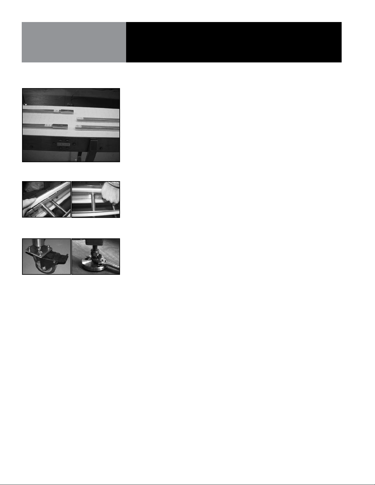
The Conveyors have been match marked for assembly in the eld, if they are not
shipped fully assembled. (See Fig. 1)
1) Wear strip then needs to be worked onto the support rails pushing it down rmly
to seat the wear strip providing a smooth slider bed surface for the belt on the
top and pushing it onto the sides on the returns. The product wear strip slides
over the support rail and is attached by a screw to the bar by the tail section of
the conveyor. The return wear strip is pressed onto the return rails. (Wear strip
is held in place on the lead in edge of wear strip in relation to direction of belt
travel). (See Fig. 2)
2) Once the wear strip is in place the belt can be installed on the frames. Belt needs
to be lifted up off bed frame and the locking pin slid to side. Once the rod is slid
into place and then locking pin moved to lock belt in place.
3) Once belt is installed guide rails can be mounted to conveyor.
• All fasteners should be checked to ensure they are tight and did not become loose in
shipment
Fig. 3
• Conveyors should be leveled on site for proper operation. On side transfers
the receiving belt or transfer surface should be located at least 1/32” below the
incoming belt or transfer surface to ensure smooth transfer.
1) Leveler height is adjusted by screwing the foot in or out with a wrench. Flats are
located at the base of the threaded rod near the foot. (See Fig. 3)
4 OM-CKCC 148673 REV. E
Page 5
Installation & Start-Up
START-UP
BELT INSTALLATION
Fig. 4
Please note before start-up to remove all tools, fasteners, or other items that could be
left behind from installation. Thoroughly clean the chain, wear strips and tracks with
an air hose or high pressure water spray.
• Prior to Installing belt bump motors to check for proper motor rotation
• Start by running your conveyor for 30 minutes to 1 hour without any product.
Listen for any unusual noises and look for signs of interference or abnormal
operations. If any problems are indicated or detected, stop conveyors immediately
and remove the obstructions or make adjustments as required.
• Repeat step 1 with product
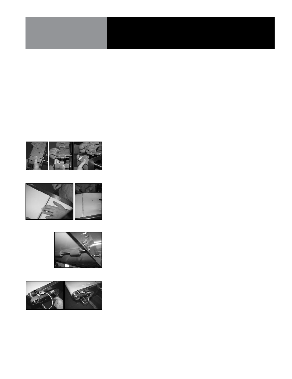
• Tabletop Chain: Belt is removed from the conveyor by separating the belt by
driving a hinge pin out of the connecting belt. This is best accomplished near the
drive or tail end of the conveyor by lifting up the belt to allow clearance for the
removal of the pin. (See Fig. 4)
When the belt is installed there will be a slight catenary sag between the snubber
roller and the sprocket. This is normal and required for proper conveyor operation.
• Mat-top Conveyor: With conveyors running under load, check for catenary
sagging. Remove or add links or rows of links to obtain proper sag. The
recommended horizontal span is 18-24’’ (457-610 mm) with a vertical sag of 3-5’’
(76-127 mm).
Fig. 5
Fig. 6
Fig. 7
1) For belts featuring synthetic powered belt for modular plastic replacement and
modular plastic belting with take-up. The take-up can be utilized to meet the
centenary sag requirement. Belts should not be under tension.
• Synthetic Belt Conveyor
1) Belt should be put in place by loosening tensioners and afxing belt in this
location by installing the pin in the lace. Align splice ngers and slide pin
through. (See Fig. 5)
2) Belt returns on top of return pulleys. (See Fig. 6)
3) Belt Tension Adjustment: Prior to putting the belt under tension mark a section
of the belt in the center that is 100” apart.
• With the belt properly installed the tensioners should be tightened using the
quick release handle or threaded nut set up. (See Fig. 7)
• Under tension the distance between the marks should grow to 100.25”. The
following chart can be used the longer the distance the more accurate the
tensioning will be as being off even a 1/16” can be detrimental to the belt.
Measurement should be taken on the center of the belt.
148673 REV. E OM-CKCC 5
Page 6

Installation & Start-Up
BELT INSTALLATION
continued
Fig. 8
• Proper belt tension should be ¼% Siegling.
Belt Length Loose Belt under tension
200” 0.5”
150” 0.375”
100” 0.25”
75” 0.1875”
50” 0.125”
25” .0625
• Ameral Beltech Ropanyl 2MI 719 .4 to .7%
Belt Length Loose Belt under tension
200” 0.8” – 1.40”
150” .6” – 1.0”
100” 0.4” – 0.7”
75” 0.3” – 0.875
50” 0.25”- 0.35”
25” 0.1”- 0.175”
• General Belt Info
Traction element Min. initial Max. initial
material tension _omin tension _omax
Polyester fabric 0.3% approx. 1%
Polyamide fabric 0.5% approx. 3%
Aramid fabric 0.2% approx. 0.3%
• Belt Tracking
1) Tension adjustment may be required to get the belt to track properly.
2) Tracking adjustment should occur with the tensioning devices engaged and
tension already preset.
3) Shaft with square end is used to adjust tension. When properly adjusted lock nut
should be tighten to secure settings. (See Fig. 8)
4) Tightening the tensioner on one side will cause the belt to move toward the
opposite side. Loosening the tensioner will cause the belt to move toward the
side being adjusted.
6 OM-CKCC 148673 REV. E
Page 7

Maintenance
Conveyors are designed and built for washdown duty and should require minimal
maintenance other than cleaning as required based on the application. It is important to
set up regular inspection and maintenance schedules. Timely preventative maintenance
and periodic inspection of the chain, sprockets and other conveyor components will ensure
long life and superior performance.
GENERAL INSPECTION
& PREVENTATIVE
MAINTENANCE (Bimonthly)
1) While the conveyors are running listen for and locate any unusual noises.
2) Check for any unusual or excessive wear patterns on the chain or wear strips. Look for
any grooves or scratches. Inspect the chain for any broken links and if a “scallop” wear
pattern has developed on the chain’s top surface, see Step 6 below.
3) Look for unusual or excessive debris, such as wear debris, product residue, or broken
container debris, especially glass.
4) Look for excessive gaps between ights due to jam-ups or overload.
Corrective Action for Steps 1-4. Remove or correct the cause. Replace worn, damaged, or
missing links as required and along with wear strips.
5) Look for pulsating or jerky chain operation.
6) Check to see if all return rollers are free for turning. (May not apply to all)
7) Examine sprockets for signs of debris build-up in tooth like pockets, along with
excessive wear.
Corrective Actions for Steps 5-7. Clean all conveyors according to instructions for Cleaning
Recommendations. Repair or replace components as needed.
8) Check catenary sags with conveyors running under load.
Corrective Action for Step 8. Remove links or rows of links to maintain proper sag. Up
to 3% of the belt length can be removed via repeating step 8 before a replacement belt in
needed.
NORMAL WEAR &
REPLACEMENT
Conduct an inspection of your belt once a month by measuring it for normal wear. Belts
may wear due to hinge/joint wear, or ight wear from wear strips and product accumulation.
Side-exing belts may also wear due to side thrust surface wear from corners.
Replace belt and other conveyor components as indicated below.
It is recommended that the belt and sprockets be replaced at the same time to ensure
optimal performance. The wear strips should also be replaced if worn, have damages or
are embedded with debris.
REPLACE YOUR BELT WHEN:
a. The belt starts jumping the sprocket teeth
b. The belt has “stretched” or elongated approximately 3%
c. Table top chain ights have worn to ½ the original ight thickness
d. Mat-top chain links have worn to about ¾ if the original link thickness
e. Side-exing chain side thrust surface wears away and exposes the pins and other metal
part, which may cut into the wear strips or other conveyor components
f. Side-exing chain side thrust surface has worn 1/16’’ (1.6 mm) or more from the
original thickness
148673 REV. E OM-CKCC 7
Page 8

Maintenance
BEARING REQUIREMENTS
POWER TRANSMISSION
LUBRICATION
Stainless Steel bearings are pre-lubed at the factory and do not require supplemental grease
before service life begins. Manufacturer recommends any lithium based NLKGI #2 grease.
Based on use, the following guidelines are recommended for lubrication
RPM Temperature (°F) Environment Condition Interval
100 32-120 Clean 6-12 months
500 32-150 Clean 2-6 months
1,000 32-210 Clean 2 weeks to 2 months
1,500 Over 210 Clean Daily to weekly
Any 32-150 Dirty Weekly to monthly
Any Over 150 Dirty Daily to 2 weeks
Any Any Temp Very Dirty Daily to weekly
Any Any Temp Very Dirty Daily to weekly
If the drive train features roller chain the chain is not lubricated at the factory but features
Daphne Chain coat #2.
The gear oil used in the reducers are:
Gear Reducer Brand Lubricant
Baldor Klubersynth UH1-6-460 (Food Grade)
Boston Gear Mobil SHC 634 (syn)
Dodge Klubersynth UH1-6-460 (Food Grade)
SEW Eurodrive Mobil 630 (M)
8 OM-CKCC 148673 REV. E
Page 9

Maintenance
MANUAL CLEANING
CLEANING
RECOMMENDATIONS
In most food handling plants, manual cleaning is used partially, if not exclusively, to remove
soils and scraps from the processing equipment. Manual cleaning can be accomplished
with hand-held, high-pressure spray nozzles and, occasionally, hand scrubbing. During
the rst rinse (knockdown), when using manual spray nozzles, any equipment above the
belt should be washed rst. The visible soils and scraps deposited on the carry-way and
associated internal structure can be removed by lifting the belt off of the carry-way and
spraying the framework with high temperature and high-pressure water. When lifting the
belt, the conveyor should be off and locked out to prevent damage to the belt and possible
injury to the cleaning personnel. Belt lifting devices, either portable or frame mounted,
lift the belt evenly across its width without causing damage to the belt. They allow easy
access during knockdown of the carry-way and internal framework of the conveyor. A
frame mounted belt lifter concept is shown in gure 4. Although it’s not recommended
because of possible belt damage, the most common way belts are lifted is to slide a bar or
pipe under the belt, lift one side, and wedge the pipe in the framework. This is done every 3
to 6 feet (.9 m - 1.8 m) depending on the width of the belt. This method can easily damage
the belt and should not be used unless absolutely necessary.
Continual cleaning action of soap and water lubrication will prevent the build-up of dirt,
debris, and spilled products. This may result in the increase wear of the chain, wear strip, and
sprockets. This can also cause increased container backline pressures, and even damaged
containers. Therefore, a thorough and regular cleaning procedure is very important to the
successful operation of any dry running conveyor line.
Note: When conveyors are not in use for long periods of time they should be covered with
plastic or drop cloth to minimize dirt and debris that can settle into chain and tracks.
Note: Before starting the conveyor check to make sure you have removed any loose tools,
fasteners, or other items that may have been left behind. Thorough clean chain, wear strips,
and track with an air hose or high pressure water spray.
RECOMMENDED CLEANING FREQUENCY:
Completely Dry Lines- Cleaning should be done daily to obtain maximum sanitation and
performance. Rinse daily and thoroughly sanitize weekly.
Partially Lubricated Lines- Cleaning and sanitation should be conducted weekly.
GENERAL GUIDELINES FOR CLEANING SOLUTIONS:
1) Recommended pH of 4-10.
2) Avoid Chlorine (Bleach), Ammonia, and Iodine.
3)
Avoid using Phosphoric Acid with plastic chains (found in many stainless steel cleaners).
TYPICAL CONVEYOR COMPONENT MATERIALS:
Belt: Acetal, Polypropylene
Table Top: Acetal, Austenitic SS
Wear Strips: SS, UHMWP, Nylatron
Sprockets: Steel, Acetal, Nylo
148673 REV. E OM-CKCC 9
Page 10

Maintenance
CLEANING
RECOMMENDATIONS
continued
CLEANING METHODS:
1) The use of a high pressure hot water rinse or steam cleaning should prove satisfactory.
Spray both the carry and return sections of the chain on each conveyor. This can be
done with the conveyors running or the chain can be stationary.
2) The use of warm water and mild soap can be used to clean the conveyors.
3) Chemical cleaners and other foaming agents may be used only if they are compatible
with the conveyor material. Manufacturer’s instructions should be followed carefully
to determine proper concentration of solutions, proper usage, and disposal.
Note: Keep water, steam and chemicals away from electrical disconnect, motors,
photo eyes, etc.
4) In some cases, cleaners or combination “cleaner/ lubricants” are applied continuously
or intermittently. Several types of automatic application systems are available.
5) Sometimes in extreme situations it may be necessary to periodically clean the chains
with a bristle brush. This cleaning should take place on the conveyor, both on the carry
and return sections.
Note: Main objective is to clean the chain carrying surface and underside as well as
the wear strips and tracks.
During the cleaning process you should also inspect your conveyor. Look and listen for
anything unusual. Remove any broken or jammed containers or pieces of container
as soon as they are detected. Use cleaning solutions to clean away excessive spillage.
Make sure to always rinse off all cleaning agents completely from the chain and conveyor
frame. Make sure to rinse under the chain as well.
10 OM-CKCC 148673 REV. E
Page 11

Parts List
148673 REV. E OM-CKCC 11
Page 12

Electrical Diagram
Schematic
12 OM-CKCC 148673 REV. E
Page 13

Service Log
Model No._______________________ Purchased From____________________
Serial No._______________________ Location___________________________
Date Purchased__________________ Date Installed_______________________
Purchase Order No._______________ For Service Call_____________________
Date Maintenance Performed Performed by
148673 REV. E OM-CKCC 13
Page 14

Service Log
Date Maintenance Performed Performed by
14 OM-CKCC 148673 REV. E
Page 15

Limited Warranty
Limited Warranty to Commercial Purchasers*
(Domestic U.S., Hawaii & Canadian Sales Only)
CapKold Equipment ("CapKold Equipment") has been skillfully manufactured, carefully
inspected and packaged to meet rigid standards of excellence. CapKold warrants its Equipment to be free from
defects in material and workmanship for twelve (12) months with the following conditions and subject to the following
limitations.
I. This parts and labor warranty is limited to CapKold Equipment sold to the original commercial purchaser/users
(but not original equipment manufacturers), at its original place of installation in the continental United States,
Hawaii and Canada.
II. Damage during shipment is to be reported to the carrier, is not covered under this warranty, and is the sole
responsibility of purchaser/user.
III. CapKold, or an authorized service representative, will repair or replace, at CapKold's sole election, any CapKold
Equipment, including but not limited to, safety valves, tipper tie, pump, motor, air components, ball valve, and
electric components, found to be defective during the warranty period. As to warranty service in the territory
described above, CapKold will absorb labor and portal to portal transportation costs (time & mileage) for the first
twelve (12) months from date of installation or fifteen (15) months from date of shipment from Groen.
IV. This warranty does not cover calibration, periodic adjustments as specified in operating instructions or manuals,
and consumable parts such as pump rotors, gaskets, packing, etc., or labor costs incurred for removal of adjacent
equipment or objects to gain access to CapKold Equipment. This warranty does not cover defects caused by
improper installation, abuse, careless operation, or improper maintenance of equipment. This warranty does not
cover damage caused by poor water quality or improper boiler maintenance.
V. THIS WARRANTY IS EXCLUSIVE AND IS IN LIEU OF ALL OTHER WARRANTIES, EXPRESSED OR IMPLIED, INCLUDING
ANY IMPLIED WARRANTY OF MERCHANTABILITY OR FITNESS FOR A PARTICULAR PURPOSE, EACH OF WHICH IS
HEREBY EXPRESSLY DISCLAIMED. THE REMEDIES DESCRIBED ABOVE ARE EXCLUSIVE AND IN NO EVENT SHALL
CAPKOLD BE LIABLE FOR SPECIAL, CONSEQUENTIAL OR INCIDENTAL DAMAGES FOR THE BREACH OR DELAY IN
PERFORMANCE OF THIS WARRANTY.
VI. CapKold Equipment is for commercial use only. If sold as a component of another (O.E.M.) manufacturer's equipment,
or if used as a consumer product, such Equipment is sold AS IS and without any warranty.
148673 REV. E OM-CKCC 15
Page 16

1055 Mendell Davis Drive • Jackson MS 39272
888-994-7636 • 601-372-3903 • Fax 888-864-7636
groen.com
PART NUMBER 148673, REV. E (03/07)
 Loading...