

Capital SL ECO Series, SCENE ECO, BASSINGTON ECO, BASSINGTON, AVEBURY Installation And Operating Instructions Manual
...
APPROVED - CONFORMING TO EN13240:2001 and
EN13240 A2:2004
APPLICABLE TO THE FOLLOWING STOVE MODELS:
VEGA EDGE 200SL (ECO)
AVEBURY (ECO)
BASSINGTON (ECO)
SCENE (ECO)
SIGMA (ECO)
STOVES MUST BE FITTED BY APPROVED, QUALIFIED AND
COMPETENT INSTALLERS
PLEASE LEAVE THIS BOOKLET WITH THE HOUSEHOLDER
Stoves operate at very high temperatures. All persons
including children and the infirm should be warned of this and not
allowed to touch any surfaces whilst in use. The operator must use
the glove provided.
SL ECO SERIES INSTRUCTION – REV.C – NOV 2018
These appliances have been approved by HETAS Ltd as an intermittent operating appliance for
burning wood and approved smokeless fuels at the nominal output of 5.0kW only.
INSTALLATION AND OPERATING
INSTRUCTIONS
1
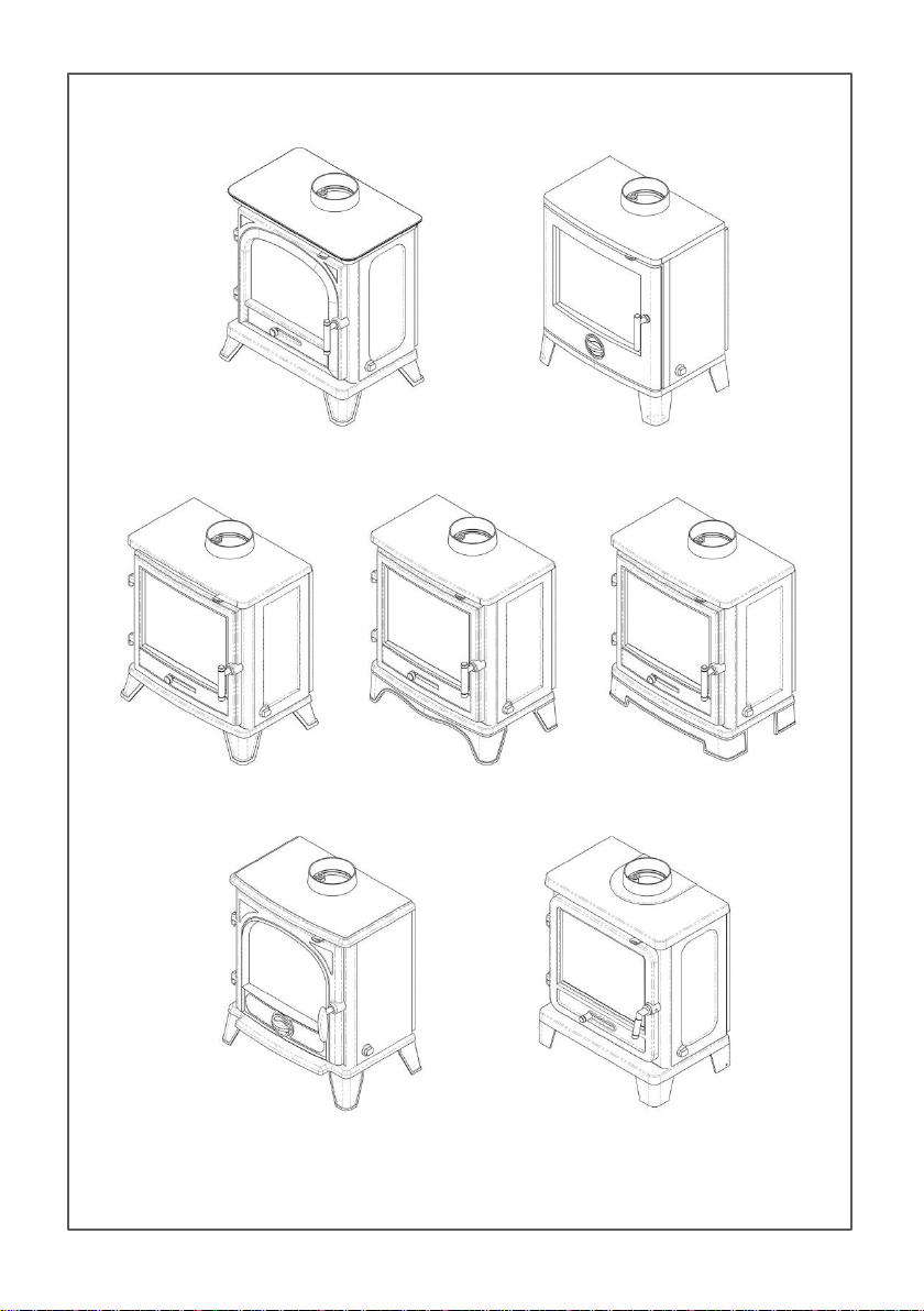
AVEBURY (ECO)
SCENE (ECO)
BASSINGTON (ECO)
STANDARD LEGS
BASSINGTON (ECO)
SKIRTED LEGS
BASSINGTON (ECO)
BASELINE LEGS
SIGMA (ECO)
VEGA EDGE 200SL (ECO)
2

CONTENTS
STOVE DIMENSIONS, OUTPUT & EFFICIENCY PAGE 04
INSTALLATION PAGE 05
OPERATION PAGE 11
GENERAL MAINTENANCE PAGE 17
SAFETY NOTES & TROUBLESHOOTING PAGE 19
STOVE ACCESSORIES PAGE 22
COMPONENT PARTS PAGE 23
TECHNICAL FICHE PAGE 30
3
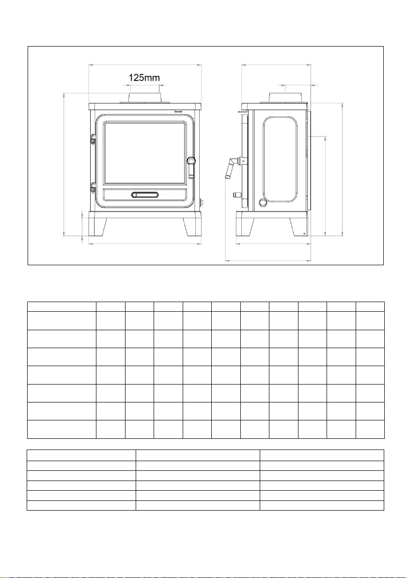
A B C D E F G H I J
AVEBURY (ECO)
531mm
630mm
80mm
325mm
114mm
350mm
365mm
453mm
590mm
531mm
BASSINGTON (ECO)
BASELINE LEGS
500mm
615mm
80mm
317mm
114mm
317mm
364mm
443mm
575mm
511mm
BASSINGTON (ECO)
SKIRTED LEGS
500mm
640mm
105mm
317mm
114mm
317mm
364mm
468mm
600mm
511mm
BASSINGTON (ECO)
STANDARD LEGS
500mm
615mm
80mm
317mm
114mm
324mm
364mm
443mm
575mm
530mm
SCENE (ECO)
485mm
635mm
95mm
327mm
114mm
324mm
352mm
456mm
595mm
504mm
SIGMA (ECO)
500mm
645mm
105mm
313mm
114mm
322mm
369mm
468mm
605mm
536mm
VEGA EDGE 200SL (ECO)
501mm
634mm
80mm
309mm
114mm
336mm
380mm
454mm
590mm
501mm
WOOD
ANTHRACITE
EFFICIENCY
84%
71.5%
FLUE GAS TEMPERATURE
244 ˚C
280˚C
EMISSION OF CO @ 13% O2
0.11%
0.24%
RATED OUTPUT
5.0kW
5.0kW
OUTPUT RANGE*
2.5 – 8.0kW
2.5 – 8.0kW
A
B D C E F G H I J
STOVE DIMENSIONS, OUTPUT AND EFFICIENCY
For illustrative purposes the Vega Edge 200SL is shown above and throughout this
manual. Other stove models may have a different appearance.
*See page 10 for ventilation requirements.
Outputs stated are under ideal test conditions carried out at SGS Environmental Services in the
Netherlands. Variations may occur due to installation, atmospheric conditions and fuel quality.
4

INSTALLATION, OPERATION AND MAINTENANCE
IMPORTANT: THIS APPLIANCE MUST BE INSTALLED BY A COMPETENT PERSON AND THE
INSTALLATION MUST COMPLY WITH BS8303 – CODE OF PRACTICE FOR INSTALLATION OF
DOMESTIC HEATING AND COOKING APPLIANCES BURNING SOLID MINERAL FUEL, NATIONAL
BUILDING REGULATIONS, LOCAL BY-LAWS AND STANDARDS AND THE REQUIREMENTS OF THE
HEALTH AND SAFETY AT WORK ACT - IN PARTICULAR:
HANDLING – ADEQUATE FACILITIES MUST BE AVAILABLE FOR LOADING, UNLOADING AND SITE
HANDLING.
FIRE CEMENT – SOME TYPES ARE CAUSTIC AND SHOULD NOT BE ALLOWED TO COME INTO
CONTACT WITH THE SKIN. IN CASE OF CONTACT WASH IMMEDIATELY WITH PLENTY OF WATER.
ASBESTOS – THESE STOVES CONTAIN NO ASBESTOS. IF THERE IS A POSSIBILITY OF DISTURBING
ANY ASBESTOS IN THE COURSE OF INSTALLATION THEN PLEASE SEEK THE GUIDANCE OF A
SPECIALIST AND USE APPROPRIATE PROTECTIVE EQUIPMENT.
METAL PARTS – WHEN INSTALLING OR SERVICING THIS STOVE CARE SHOULD BE TAKEN TO AVOID
THE POSSIBILITY OF PERSONAL INJURY
UNLESS THE INSTALLER IS QUALIFIED TO APPROVE INSTALLATION THEN APPROVAL MUST BE
SOUGHT FROM YOUR LOCAL BUILDING CONTROL DEPARTMENT. THE SUPPLIERS ACCEPT NO
RESPONSIBILITY IF THIS ADVICE IS NOT FOLLOWED. THIS APPLIANCE HAS BEEN EXTENSIVELY
TESTED FOR SAFETY AND EFFICIENCY, DO NOT ATTEMPT TO MODIFY IT. ALWAYS USE GENUINE
REPLACEMENT PARTS AS RECOMMENDED BY YOUR SUPPLIER. FAILURE TO ADHERE TO THIS
ADVICE WILL INVALIDATE YOUR GUARANTEE.
TRY TO AVOID FITTING AN EXTRACTOR FAN IN THE SAME ROOM AS THIS STOVE. IF THIS IS
UNAVOIDABLE THEN SEEK SPECIALIST ADVICE TO ENSURE THAT THE INSTALLATION IS TESTED
FOR SAFETY. A SUITABLE TEST COMPRISES CHECKING FOR SPILLAGE IF THE ROOM WHERE THE
APPLIANCE IS FITTED IS SUBJECTED TO THE GREATEST POSSIBLE DEPRESSURISATION. THIS
MEANS FIRING THE APPLIANCE WITH ALL THE EXTRACT FANS IN THE BUILDING OPERATING AT
THEIR MAXIMUM AND WITH ALL DOORS, ADJUSTABLE VENTILATORS AND WINDOWS CLOSED.
IF SPILLAGE OCCURS THEN ADDITIONAL PERMANENT VENTILATION DIRECT FROM OUTSIDE WILL
BE REQUIRED. ONCE THE ADDITIONAL VENTILATION IS FITTED, RETEST AS NOTED ABOVE,
IT IS ESSENTIAL AND REQUIRED BY BUILDING REGULATIONS THAT A CARBON MONOXIDE (CO)
ALARM IS INSTALLED IN THE SAME ROOM AS THIS STOVE.
THIS STOVE MUST HAVE ITS OWN CHIMNEY AND MUST NOT SHARE A CHIMNEY WITH ANOTHER
APPLIANCE.
THIS STOVE IS FOR INTERMITTENT USE ONLY AND SHOULD BE SHUT DOWN OVERNIGHT.
VENTILATION MAY BE REQUIRED INTO YOUR ROOM, PLEASE SEE PAGE 10.
5

INSTALLATION
Once the installation is complete, the installer must advise the householder on
the correct use of the stove and warn them to use only the recommended fuels
listed in this document. The installer must also advise the householder on the
actions to be taken should smoke or fumes be emitted from the stove.
This stove must not share a chimney with any other appliance
Where the chimney is believed to have previously served an open fire
installation it is possible that the higher flue gas temperature from a closed
appliance may loosen deposits that were previously firmly adhered, with the
consequent risk of flue blockage. It is therefore recommended that the chimney
be swept a second time within a month of regular use after installation.
Check the chimney is in good condition, dry, free from cracks, leaks and
obstructions. The diameter of the flue should be no more than 230mm. If this
cannot be met then an appropriate liner should be fitted by a suitably approved
method.
A 125mm flue liner may be used in accordance with the Building Regulations.
The chimney and connecting flue pipe should not narrow to less than the size of
the outlet socket (collar) of the stove at any point. It is essential that only
recommended fuels are used – see page 15 for more information.
The chimney height and the position of the chimney terminal must conform to
Building Regulations and the latest edition of BS EN 15287-1:2007, Design,
Installation and Commissioning of Chimneys should be followed.
A flue draught of minimum 12 Pascals is required for satisfactory appliance
performance. The flue draught should be checked under fire at high output and
if it exceeds 25Pa, a draught stabiliser may be required so that the rate of
burning can be controlled, and to prevent possible over-firing.
If you have any doubts about the suitability of your chimney, consult your local
dealer/stockist. He will also be able to provide advice about the possible need
for a specialist cowl.
6
The chimney must be swept before connection to the stove and swept every
twelve months thereafter. It is recommended that your chimney is swept every
six months.
An existing fireplace opening can be modified to accommodate the stove. The
following pages identify some typical installation scenarios and provides the
necessary specific installation information for your new stove. Always consult
your stove supplier for a detailed survey of your particular circumstances.
To make it easier to handle the stove on installation, remove the baffle plates,
bricks and door. Place in a secure place to avoid damage. Refit after
installation.
Upon completion of installation, the appliance should be checked under fire for
soundness of joints and seals, and also that all smoke and fumes are taken from
the appliance, up the chimney and emitted safely.
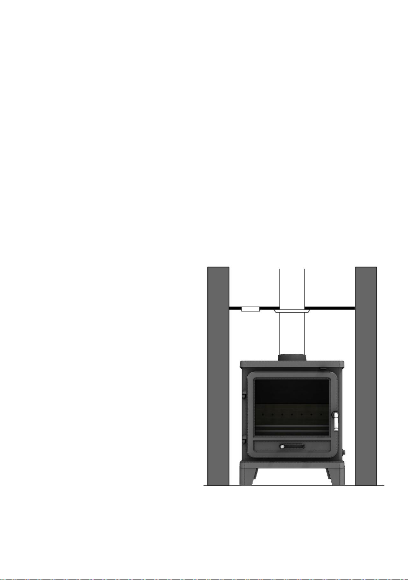
Typical Installation for Inglenook Fireplaces – top flue
Inglenook fireplaces can have very
large bore chimneys. Check with your
installer – you are likely to require a
stainless steel flexible liner for solid
fuel if your chimney is larger than
230mm x 230mm. A closure plate
with access for cleaning may also be
required together with a short length
of flue pipe of the same diameter as
the stove flue collar.
7
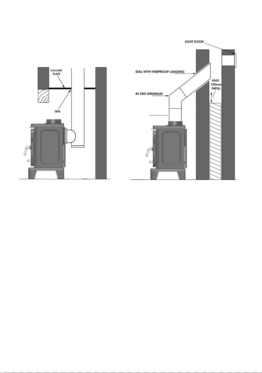
MINIMUM 600MM STRAIGHT
BEFORE 45 DEG BEND.
Typical Installation for Inglenook Typical Installation Into In-filled
Fireplaces – rear flue – Side View Masonry Fireplaces
SPECIFIC INSTALLATION INFORMATION
Legs
Remove the legs from inside the stove. Note that the Bassington legs are not
contained inside the stove but packaged separately. Carefully lay the stove on
its back and using the screws provided fit the legs in place. Carefully set the
stove upright and check that all internal components are correctly positioned.
Clearances
If the stoves are to be installed adjacent to materials that can catch fire like
wood then the following clearances must be adhered to:
Clearance to rear = 600mm
Clearance to sides = 600mm
The stove can be recessed into a suitably sized fireplace built from noncombustible materials, but a permanent free air gap of at least 100mm should
be left around the sides and top to obtain maximum heat output and for access
to the rear of the stove.
8
1
12mm
NON-COMBUSTIBLE
MATERIAL HEARTH
It is possible to fit the stove with less clearance around it – down to 50mm, but
the non-combustible material around it must be at least 150mm thick. This is
normally achieved when installing into a standard brick-built chimney breast
with double thickness walls to the rear and sides of the builder’s opening. Take
care that the wall finish is suitable to withstand temperatures of up to 200oC.
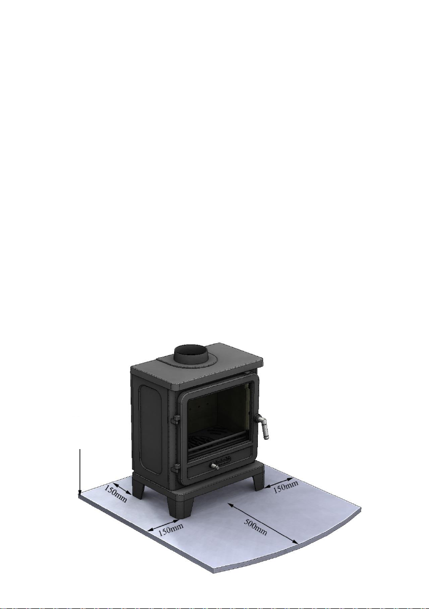
Hearths
Allow an apron of at least 225mm at the front of the stove and 150mm on either
side. Care should be taken to level the stove and secure the hearth. If existing
floors do not have adequate load bearing capacity then suitable modifications
must be adopted.
When the stove is in the desired position, fix the brackets provided to the back
feet and level the stove using the levelling screws, then mark the hearth through
the holes, remove the stove, and drill and plug the hearth for securing the stove.
Light Duty Hearths
Excluding the Bassington Baseline model, so long as the stove is installed in
accordance with the minimum clearance distances below then a light duty
hearth may be placed on a wooden floor. Note that all clearance distances to
combustible materials must be adhered to (see page 8).
9
SCREWS
Ventilation Into a Room For Combustion Air is an Essential Requirement.
Any apertures provided for this purpose must not be restricted or blocked.
Flues Without a Flue Draft Stabiliser 2.5kW-5kW Output
When installing without a flue draft stabiliser into houses built before 2008, no
additional permanent ventilation will be required.* Houses built after this date will
require additional means of permanent ventilation direct to outside of at least 4400
mm2. * Note: Installers must verify adequate draw and install ventilation if required. See Appendix F of
Building Regulations Approved Document J.
5kW-8kW Output - If you are intending to burn the stove above the independently
tested 5kW output, then a permanently open air vent into the room where the stove is
situated will be required. For house built before 2008, the vent must have a free area of
at least 1650mm2. For house built after 2008, the vent must have a free area of at least
4400mm2.
Flues With a Flue Draft Stabiliser 2.5kW-5kW Output
When installing with a flue draft stabiliser into houses built before 2008, at least
1500mm2 additional means of permanent ventilation direct to outside is required.
Houses built after this date will require additional means of permanent ventilation direct
to outside of at least 6800 mm2.
5kW-8kW Output - If you are intending to burn the stove above the independently
tested 5kW output, then a permanently open air vent into the room where the stove is
situated will be required. For house built before 2008, the vent must have a free area of
at least 4050mm2. For house built after 2008, the vent must have a free area of at least
6800mm2.
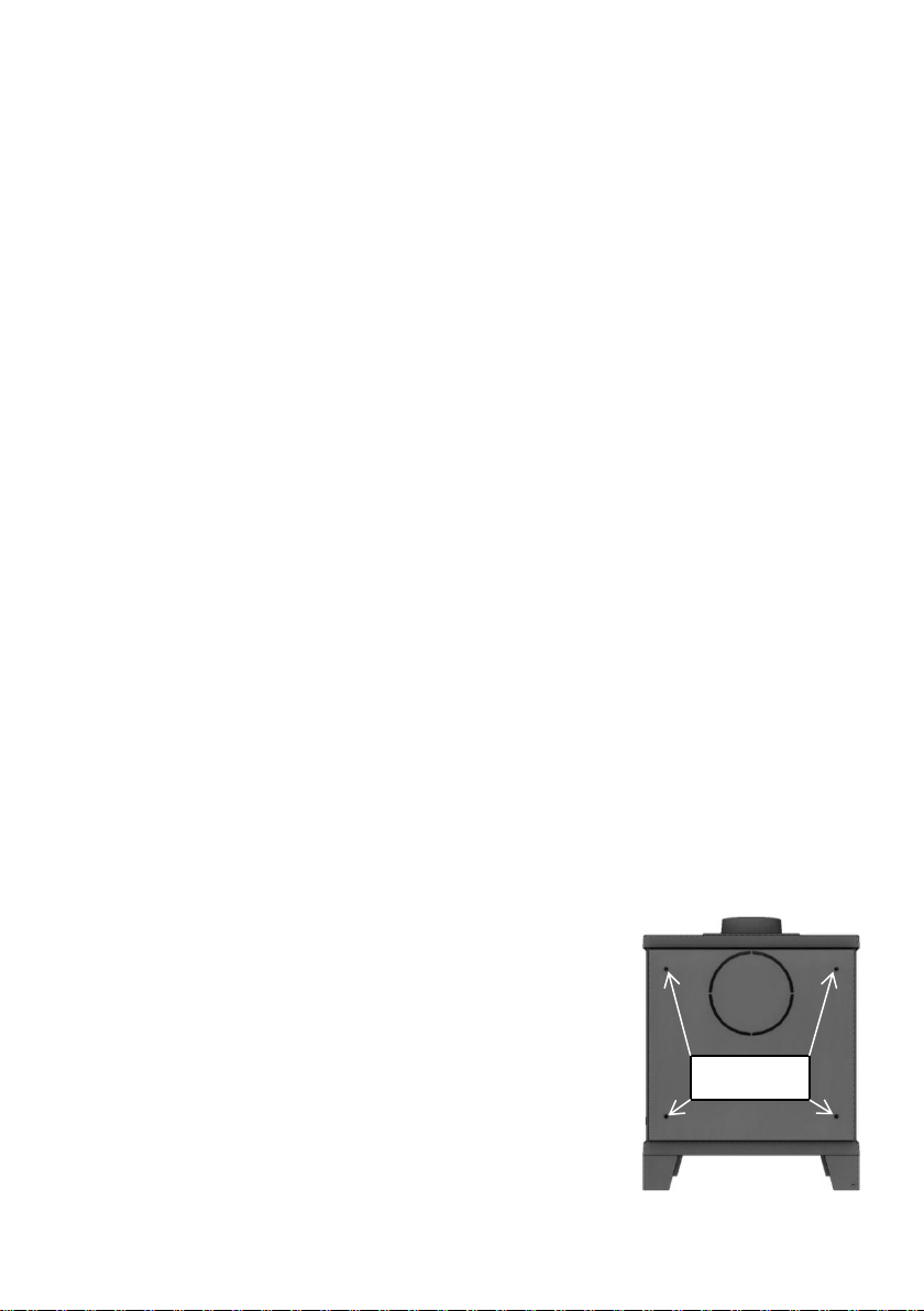
Top or Rear Flue
Remove the collar and accessory pack from the stove. The
stove will arrive with the blanking plate fitted to the rear.
This can be removed if required allowing the collar to be
fitted for rear flue installations. The circular cut out in the
rear heat shield must be removed to enable this style of
connection – see image.
Remove the panel from the stove by unscrewing the four
screws and then remove the circular cut out for rear flue
installations. Replace the rear heat shield. Remember to fit
the blanking plate to the unused flue position if it has been
removed.
10
 Loading...