

Page 1
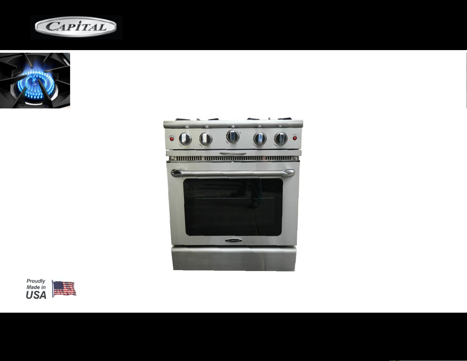
USE AND CARE & INSTALLATION GUIDE
MCOR GAS MANUAL CLEAN
MCOR SERIES
Page 2

TABLE OF CONTENTS
Features 3
Models
Warnings
Safety Practices / Electrical, General 9
Safety Practices / Cooking 10-11
Oven Parts Identification 12
Range Parts Identification
Using The Range-Top / Power Burners
Using The RangeTop 15-16-17
Using Your Oven 17-18-19-20
Using Your Oven - Self Clean Mode 21-22
Care And Maintenance 23
Care And Maintenance / Locating Rating Plate
Troubleshooting 25-26
Installation Instructions 27
Table Of Contents 28
Service / Warranty 45
4-5-6-7
8
13
14
24
CULINARIAN SERIES
2
Page 3
MCOR GAS RANGES FEATURES:
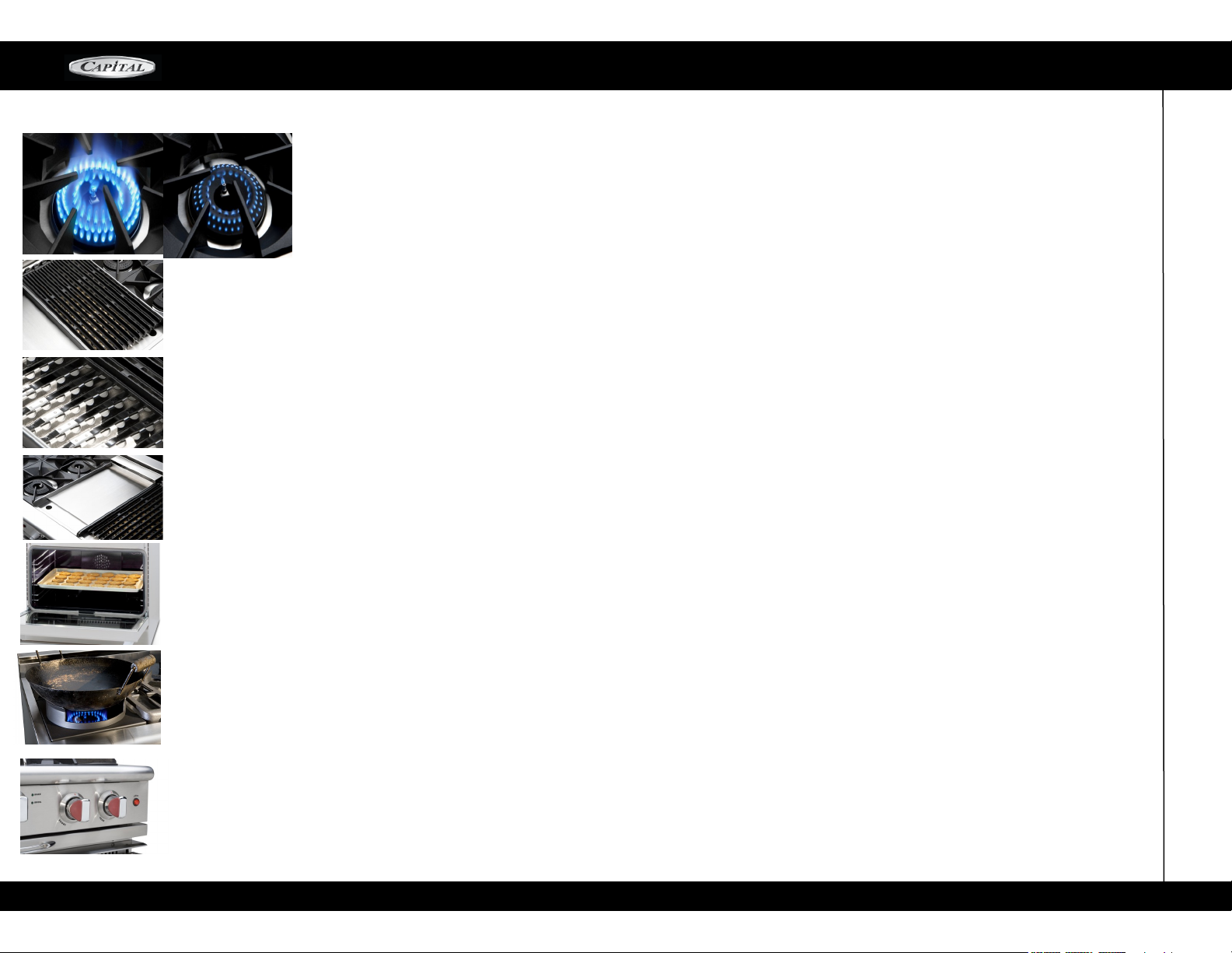
MOST POWERFUL OPEN-TOP BURNERS IN THE INDUSTRY:
All ranges are equipped with one small pan burner rated at 8,000 btu / hr,
All the others burners are rated at 23,000 Btu / hr to deliver intense commercial kitchen heat to sauté
food and all burners are capable of turning down to give simmer.
COMMERCIAL QUALITY TRADITIONAL BBQ-GRILL GRATES
The Culinarian Gas Convection Ranges feature our exclusive BBQ-Grill w/ CAST IRON channeling grates
that help reduce flare-ups by channeling the grease away from the burner into spillage tray.
HYBRID RADIANTS
With Ceramic Rods Encased in Stainless Steel Sheet Metal for reduced flare-ups and Prolonged life.
THERMO-GRIDDLE
Our solid stainless steel thermostatically controlled Griddle Plate Gives you precise control over the Griddle
area. From 18,000 BTUs on 12" Griddle section and 30,000 BTUs on 24" Griddle section Capital all stainless
steel Griddle Plates will never rust! Guaranteed!
MCOR SERIES
LARGE OVEN CAPACITY
Large enough to accommodate restaurant
Size Baking Tray
Cast Iron Wok Grate As Optional Accessory
STAY-KOOL KNOBS
Our restaurant grade, die cast chrome plated metal knobs feature bold red graphics for easy readings of settings. Plastic inserts that stay cool to the touch when using your Range (Available in
Black or Cabernet Red.).
3
Page 4
30” MODELS
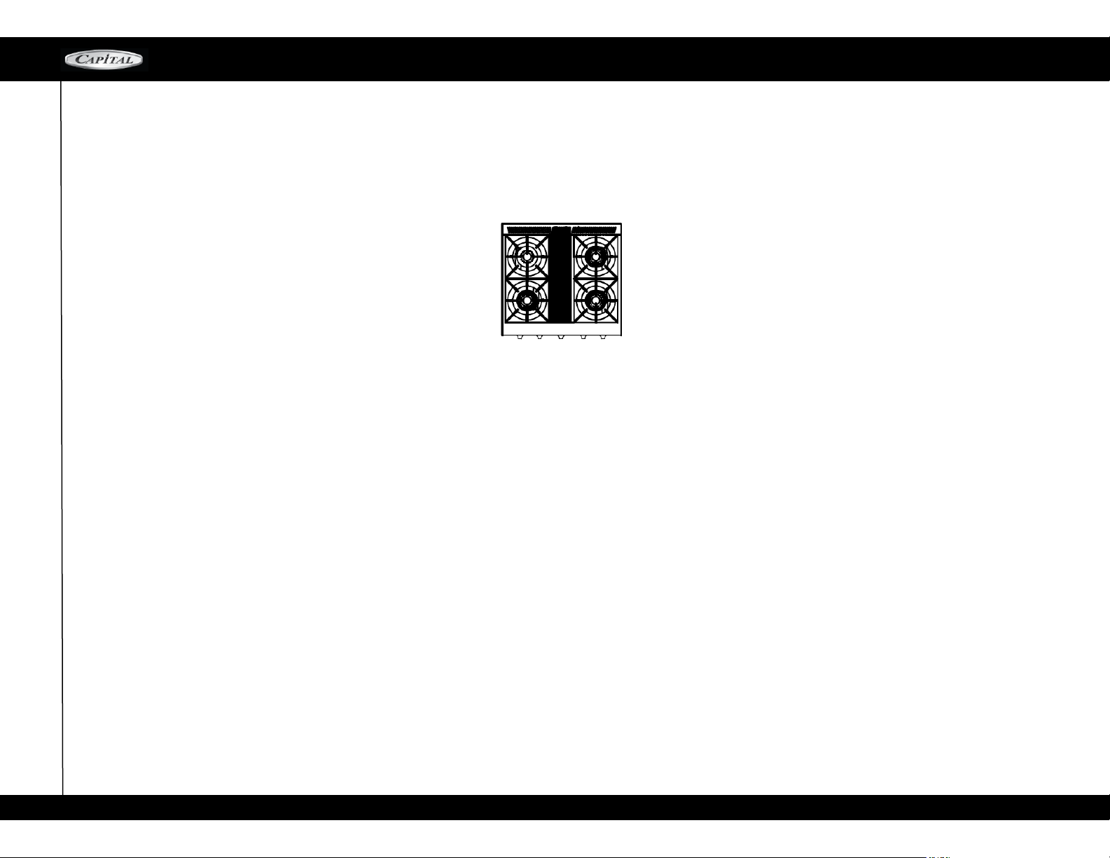
30” MCOR SERIES MANUAL-CLEAN MODELS
MCOR304
MCOR SERIES
4
Page 5
36” MODELSS
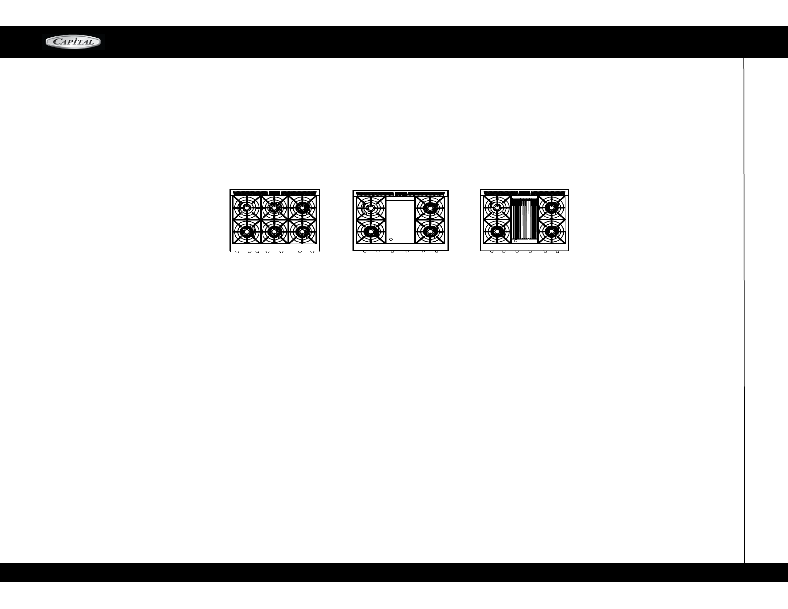
36” MCOR SERIES MANUAL-CLEAN MODELS
MCOR SERIES
MCOR366
MCOR362G2
MCOR362B2
5
Page 6
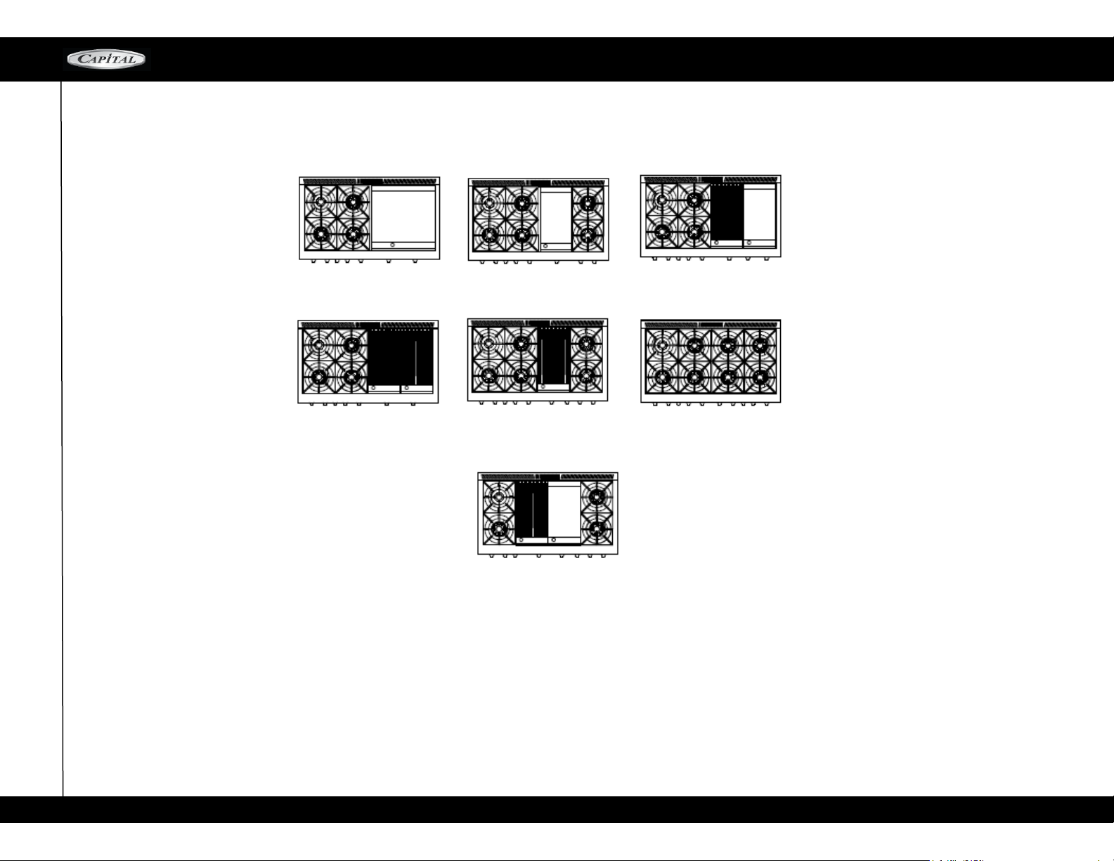
48” MODELS
48” MCOR SERIES MANUAL-CLEAN MODELS
MCOR SERIES
MCOR484GG
MCOR484BB
MCOR484G2
MCOR484B2
MCOR482BG2
MCOR484BG
MCOR488
6
Page 7

60” MODELS
MCOR SERIES
7
Page 8
WARNINGS!
MCOR SERIES
WARNING! If the information in this manual is not
followed exactly, a fire or explosion may result
causing property damage, personal injury or death.
WHAT TO DO IF YOU SMELL GAS
Do not try to light any appliance
Do not touch any electrical switch
Do not use any phone in your building
Immediately call your gas supplier from a
neighbors phone. Follow the gas supplier's instructions.
If you can not reach your gas supplier, call the
fire department
Installation and service must be performed by a
qualified installer, service agency or the gas supplier.
The appliance and its individual shutoff valve must be
disconnected from the gas supply piping system
during any pressure testing of that system on test
pressures in excess of 5 psi (35 kpa).
The appliance must be isolated from the gas supply piping
system by closing its individual manual shutoff
valve during any pressure testing of the gas supply
WARNING! Disconnect Power before installing.
Before turning power ON, be sure that all
controls are in the OFF position.
IMPORTANT! Installation must conform with local
codes or, in the absence of local codes, with the National fuel Gas Code, ANSI Z223.1/NFPA54.
IN CASE FIRE
Smother flames with a close fitting lid, or any
metal tray.
Turn OFF the burner. Be careful to prevent burns. If
the flames do not extinguish, immediately
evacuate and call the fire department
NEVER pick up a flaming pan. By doing so, you
may be burned.
DO NOT use water or a wet dishcloth on
fire. A violent steam explosion will result.
Use a fire extinguisher only if:
You have CLASS ABC extinguisher and you
know how to operate it.
The fire is small and contained in the area where it
started.
The fire department has been called.
You can fight the fire with your back to the exit.
FOR YOUR SAFETY! If You Smell Gas:
Shut off gas to the appliance. Extinguish any open
flames. If odor persists, immediately call your gas supplier.
Th is appli anc e is de sig ned for easy installation
and operation. However, we recommend that you
read all sections of this manual before installation and
that your range is installed by an approved gas installation technician capable of reviewing and performing the
manufacturers installation checklist included in your
information packet.
The installation of appliances assigned for manufactured (mobile) home installation must conform with the
Manufactured Home Construction and Safety and Safety
Standard, Title 24 CFR, Part 3280 or, when such standard is not applicable. Refer to
ANSI/NCSBCS A225.1, or with local codes as applicable.
The installation of appliances designed for
Recreation Park Trailers must conform with state
or other codes or, in the absence of such codes,
with the standard for Recreational Park Trailers,
ANSI A119.5.
The appliance, when installed, must be electrically
grounded in accordance with local codes or, in
the absence of local codes, with the National
Electrical Code, ANSI/NFPA 70
WARNING! If the information in this manual is not
followed exactly, a fire or explosion may result,
causing property damage, personal injury or death.
Please read the installation, operating and maintenance instructions thoroughly before use.
CAUTION! When connecting the unit to propane
gas, make certain the propane tank is equipped
with its own high-pressure regulator in addition to
the pressure regulator supplied with the range.
The pressure of the gas supplied to the appliance
must not exceed 14" (34.57 mB) water column
from the propane gas tank to the pressure
regulator.
CAUTION! Do not store or use gasoline or any
other flammable liquids in the vicinity of this or any
other appliance.
PLEASE RETAIN THIS
MANUAL FOR FUTURE
REFERENCE!
PLEASE NOTE:
In the Commonwealth of Massachusetts, gas connection must be performed by a licensed plumber
or licensed gas fitter.
IMPORTANT!: For fire safety and correct operation
a back guard must be installed on all ranges prior to
use! All ranges are shipped with a standard 3" Island
Trim which is compatible with non-combustible back
wall installations ONLY! If desired or if the minimum
distance to a combustible back wall is not met (see
Fig. 2A) one of two additional back guards heights
may be ordered and installed (Low Back – 9", or
High Back – 18"). Refer to the Installation Instructions
accompanying this appliance for assembly instructions
8
Page 9
SAF E T Y P RAC T I C E S / E LE C T RI C AL, G E NE R AL
CULINARIAN SERIES
ELECTRICAL SAFETY:
Electrical Requirements and Grounding Instructions
NOTE: ALL MODELS.
IN CASE OF AN ELECTRICAL FAILURE
If for any reason a gas control knob is turned ON and
there is no electric power to operate the electronic
igniters on the range burners, turn OFF the gas
control knob and wait 5 minutes for the g as to
dissipate before lighting the range burner manually.
To light the range burners manually, carefully hold
a lighted match to the burner ports and turn the
gas control knob to Hl. During a power failure, you
can manually light the range burners with match.
Note: The gas oven, grill, Thermo-griddle'"' and
infrared oven broiler burners CANNOT be lit manually during a power failure.
WARNING! Do not under any circumstances cut
or remove the separate ground wire or the third
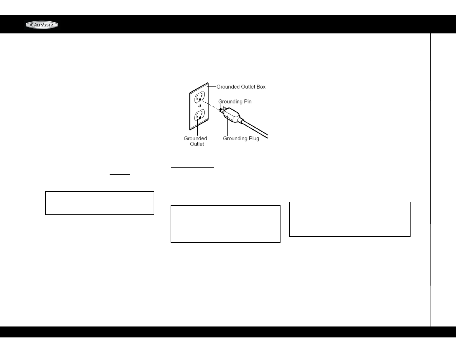
(ground) prong from the power cord plug.
PLEASE READ CAREFULLY:
All MCOR gas range models require an electrical circuit
rated at 120 volts, 60 Hz., and 12 Amps. For 30” and
36” 20 Amps. For 48” (VERIFY) For personal safety,
this appliance must be connected to a properly
grounded and polarized electrical power supply. Always disc onnect the elect rical p lug from the wall
rec eptacle before servicing this unit. See Installation
Instructions for electrical requirements and grounding
instructions.
It is the personal responsibility and obligation of you,
the user, to have this appliance connected to the electrical power supply in accordance with the National
Electrical Code and/or applicable local codes and
ordinances by a qualified electrician.
*It is recommended that a dedicated circuit servicing
this appliance be provided.
GENERAL SAFETY:
Yo ur ne w ran ge ha s bee n des ign ed to be a
safe, reliable appliance when properly installed,
used and maintained. If not properly used, it could
be dangerous. Read ALL the instructions in this
Use and Care Guide carefully before using this range.
WARNING! These precautions will reduce the
risk of burns, electric shock, fire, and injury to
persons. Us e extreme care when using this
restaurant caliber range as this appliance
provides intense heat and can increase accident potential.
Safety precautions must be followed when
using any kitchen appliance.
Insure proper installation and servicing.
Follow the installation instructions provided
with this product. Have the range installed
and grounded by a qualified technician.
Have the installer demonstrate how to use this
appliance and show you where the gas supply
shut off valve is located so that you know how
and where to turn off the gas to the range.
If you smell gas, your installer has not done a proper
job of che ck ing for l eaks. If the c onnections
are n ot perfectly tight, you can have a s mall
leak and there fore sm ell of fa int g as odor.
Fi nding a gas le ak is not a "d o-it-yours el f"
procedure. Some leaks can only be found with
th e bu rn er con trol i n the "ON" position a nd a
qualified service technician must do this.
In the event a burner goes out and gas escapes,
open a window or door immediately. DO NOT
attempt to use the range until the gas has had time
to dissipate. Wait at least 5 minutes before using
the range again.
DO NOT repair or replace any part of the appliance
unless specifically recommended in this manual.
Al l oth er se r vi cing s h oul d b e r efe r re d to a
qualified technician.
Children SHOULD NOT be left alone or unattended
in an area where appliances are in us e. They
should never be allowed to sit or stand on any part
of the appliance.
CAUTION! Do not store items of interest to children
over the range or behind it. If children should climb
onto the appliance to reach these items, they could
be seriously injured.
NEVER use any part of the range for storage.
Flammable materials can catch fire and plastic
items may melt or ignite.
If the range is near a window, be certain the
curtains do not blow over or near the range burners, griddle or broiler section; they could catch
fire and cause serious damage and injury.
DO NOT USE WATER ON GREASE FIRES! Turn
appliance off and smother fire with baking soda
or use a dry chemical or foam-type extinguisher.
9
Page 10
SAFETY PRACTICES / COOKING
MCOR SERIES
NEVER let clothing, potholders, or other flammable
materials come into contact with or too close to any
element, burner, or burner grate until it has cooled.
Fabric may ignite and result in personal injury.
COOKING SAFETY:
USE ONLY DRY POTHOLDERS. Moist or damp
potholders on hot surfaces may cause burns from
the steam. Do not use a towel or other bulky cloth
in place of potholders. Do not let potholders touch
hot elements, hot burners, or burner grates.
FOR PERSONAL SAFETY, wear proper apparel.
Loose fitting garments or hanging sleeves should
never be worn while using this appliance. Some
synthetic fabrics are highly flammable and should
not be worn while cooking.
DO N OT us e a lu minum foil as a shiel d agains t
fo od s pills o r dripping s around the bur ne rs o r
control panel area. This could obstruct the flow of
com bustion and ventilated air. This can damage
the finish of the range.
WARNING! This a pplia nce is for c ooking!
Based on safety co nsiderations, never us e
th e range t o warm or heat a room. Such use can
damage the range.
DO NOT TOUCH THE BURNER GRATES OR THE
IMMEDIATE SURROUNDING AREAS adjacent to
the burners. When in use these areas may become
hot enough to cause burns.
NEVER leave the range unattended when using
high flame settings. Boil- ov er s c ause smoki ng
and greasy spills that may ignite. More importantly,
if the bur ne r flame s are s mothe re d, unb urned
gas will es ca pe into the room.
ONLY certain types of glass, heat proof glass-
ceramic, ceramic earthenware or other glazed
utensils are suitable for range use. Other types of
utensils may break with sudden
temperature changes. Use only on low or medium
heat settings according to the utensil manufacturer's
directions.
DO NOT HEAT UNOPENED FOOD CONTAINERS.
A buildup of pressure may cause the container to burst
and cause injury
DURING COOKING, set the burner control so that
th e flam e heats o nly the bottom of the pan an d
does not extend beyond the bottom of the pan.
USE CAUT IO N to ensure that drafts like those
from forced air vents or fans do not blow flammable
materials toward the flames or push the flames so
that they extend beyond the edges of the pot.
TO MI NIMI ZE ACCID E NT, position handles of
utensil inwar d so that they do not e xtend o ver
adj acent work areas, cooking are as o r the edge
of the range.
HO L D TH E HA N D L E of the pan to p r e v e n t
movement of the utensil when stirring food.
DO NOT USE the B BQ gr il l t op se ction for
gri lling e xcess ively fatt y meat s or products that
promote flare-ups.
GREASE IS FLAMMABLE. Let h ot grease cool
before attempting to handle it. Avoid letting grease
deposits to collect. Clean after each use.
KEEP BURNER PORTS CLEAN. T his is essen-
tial for proper lighting and maintenance of the
burners. I t is n ec es sary to clean th e bur ner
ports whe n t h ere is a boi l ov er or whe n th e
bur ner does not light though the electronic igniters
click.
CLEAN THE RANGE-TOP SECTION WITH CAUTION.
Avoid steam burns; do not use a wet sponge or cloth to
clean the range while it is hot. Some cleaners produce
noxious fumes if applied to a hot surface. Follow directions• provided by the cleaner manufacturer.
BE SURE ALL RANGE CONTROLS ARE TURNED
OFF and the range is cool before using any type of
aerosol cleaner on or around the range. The chemical
that produces the spraying action could, in the presence
of heat, ignite or cause metal parts to corrode. Only an
authorized service technician should perform Service.
Technicians must disconnect the power supply before
servicing this unit.
CLEAN THE VENTILATION HOOD and filters above
the range frequently so grease deposits from cooking
vapors do not accumulate on them.
IN CASE OF FIRE or when intentionally using "flaming"
liquor or other spirits on the range, follow hood manufacturer's instructions.
INSTALL A SMOKE DETECTOR in or near the kitchen.
TURN THE KNOB CONTROL TO OFF if a burner goes
out and gas escapes. Open a window or door. DO NOT
attempt to use the range until the gas has had time to
dissipate.
WARNING! To redu ce th e r is k of tipping of the
appliance, it must be secured by a properly installed
an ti- tip dev ice. Veri fy tha t t he anti - ti p d evi ce
is engaged per installation instructions (note:
anti -tip device is required on all gas ranges.)
SEE PAGE 39
When using the oven: DO NOT touch the
interior s u r f a c e s of the o ve n o r the
e xt e r i o r ar ea imm ediat ely s urrou nding
the do or. Inte ri or oven surfaces become
hot enough to cause burns. The heat deflector, which deflects heat away from the
range and the trim on t he top and si de s
10
Page 11
SAFETY PRACTICES / COOKING
MCOR SERIES
Place oven racks in desired position while oven is
cool. If a rack must be removed while the oven is
ho t, do n ot let the pot hol der s con tac t the hot
infrared burner.
Us e ca u t ions when open i n g th e ove n doo r ;
let hot stea m o r air es cap e b e for e r emov ing
or replacing foods.
DO N OT remove t he door gas ket.
It is essential for a good seal during baking.
BE CAREFUL not to damage the glass covering the
infrared broiler in the gas oven. If the glass is damaged,
air can enter the distribution box behind the glass, possibly resulting in an explosion.
In the eve nt that personal clothing c atches fire,
DROP AND ROLL immediately to extinguish flames.
DO NOT obs truct the pat h of c omb us t io n or ven-
tilation air.
For safety reasons and to avoid equipment damage,
never sit, stand, or lean on any part of the range.
Se rv i ce s ho u ld on ly be p er f or me d b y a quali-
fied, Factory Authorized Service Technician. Technicians must disconnect the power supply before servicing
this unit.
Remove all packing materials and labels from your
1.
appliance. If the installer has not set up your appliance,
please do it before using it.
Place the oven racks in the proper position before
2.
turning on the oven.
Fo r c orrect rack positio n, ch ec k y our r ec ipe. The
most frequently used position is numbe r 2. The
rack positions are numbered from the bottom to the
top as in the floors of a building.
CA UTION! Do not use alumi num f oi l to cover
the oven racks or to line the oven. Heat can be
trapped beneath the foil, this can cause damage
to the oven and food may not cook correctly.
Before BAKING and BROILING
3.
Tu rn on the oven and bro iler burne rs on e at a
time for 20 to 30 minutes each. This burns off the
manufacturing oils used by the factory. Turn the
ove n bu rne r on to 450 °F a nd the n th e br oil e r
burn e r ON t o "Br o i l " . Be sure t o tu r n on t h e
ventilator above yo ur ran ge while these burners
are on, as there will be an odor.
CA LIFOR NI A PR OPOSITI ON 6 5 W ARN IN G:
The burning of gas cooking fuel generates some
by products whic h are on the list of substances
whic h a re kn own b y t he State of Califo rnia to
cause Cancer or reproductive harm. California law
requires business to warn customers of potential
expos ure to t he s e su bst anc es. To m ini miz e
exposure to these substances, always operate this
unit according to the instructions contained in this
booklet and provide good ventilation to the room
when cooking with gas.
11
Page 12
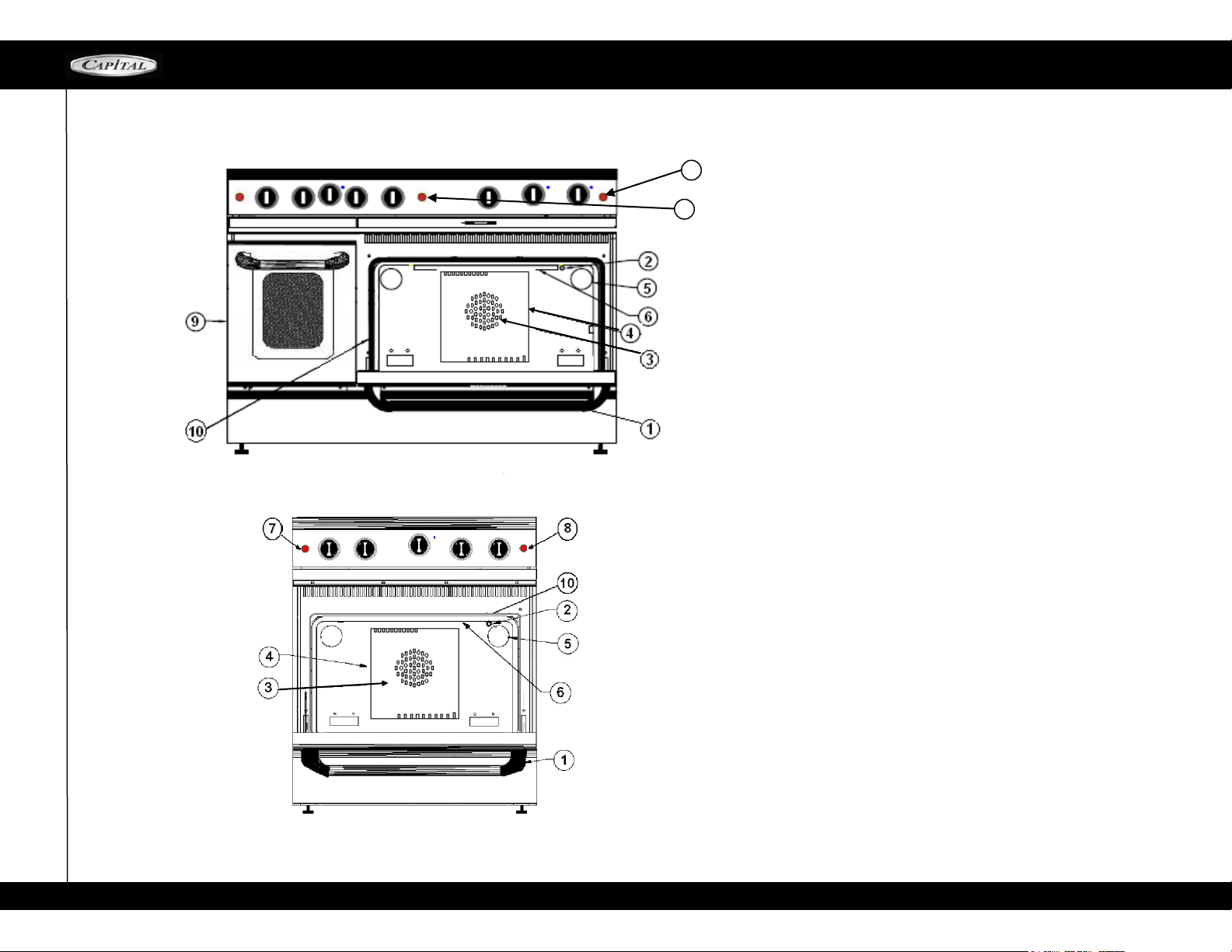
OVEN RANGE PART IDENTIFICATION
MCOR -SERIES
8
7
1.Large Oven
2.Oven Thermostat Sensing Bulb
3.Convection Baffle
4.Convection Fan (center back
wall of oven can behind baffle)
5.Oven Light
6.Broiler Burner
7.Oven Fan Switch
8.Oven Light Switch
9.Small Oven
10.Oven Gasket
12
Page 13
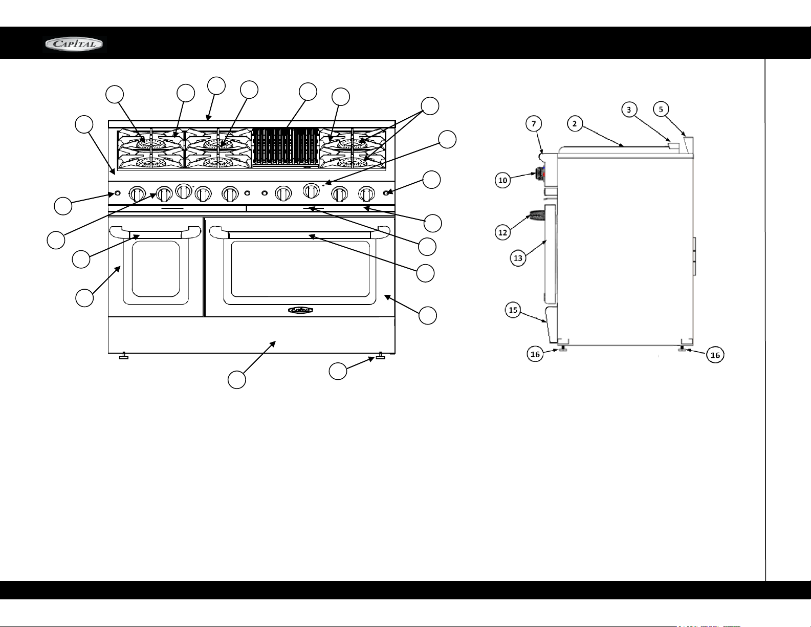
RANGE PARTS IDENTIFICATION
MCOR-SERIES
10
7
17
7
9
5
14
6
1
15
4
6
16
18
12
13
1
11
8
9
1.Burner 23K BTU
2.Griddle Plate
3.Griddle Flue Cover
4.BBQ-Grill
5.Small Oven Door Handle
6.Cast Iron Grate
7.Bull Nose
8.Indicating Lights
9.Switch (Light & Fan)
10.Knobs
11.Drip Pan Handle
12.Oven Door Handle
13.Door Panel
14 Small Door Panel
15 Kick Plate
16.Adjustable Leg
17. Small Pan Burner
18. Stainless Handle
13
Page 14
USING THE RANGE-TOP BURNERS
MCOR SERIES
CULINARIAN BURNERS
Your new gas range is equipped with the latest in
bur n er t echn ology . The Culi nari an b urne rs a re
mos t ef fici ent and most pow erful bur ners
(2 3,000 BTU /HR ) in the h ouseh old appl i ance
ind ustry
All ranges are equipped with one small
pan burner at back left of the range.
SIMMERING BURNERS HAVE
All range-top has exceptionally low simmering capabilities
When using the simmer feature, turn the main
burner knob down to the simmer position.
ELECTRONIC IGNITERS
If a burner does not ignite, listen for the clicking
sound. If th e bur ner d oes n ot c l ick, TURN
OFF THE BUR N ER. Chec k th e ci rcui t
bre aker f o r a b l own fus e or a tripped circuit
breaker. If the ignite r still fail s to operate, see
page 19 "T ro ubleshooting", "Before calling For
Service".
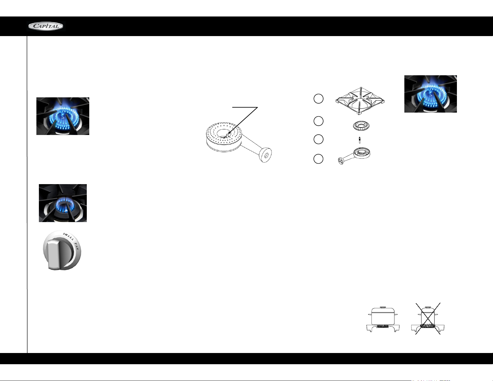
PORT & IGNITER
(KEEP CLEAN)
Al l the r ange- to p b ur ners ha ve elec tr onic sp ark ignition.
NOTE. If you are using propane gas, a slight pop
flash may occur at the burner ports a few seconds
af ter t he bur ner h as b een tur ned " off ". T his
"extinction pop" is normal for propane gas.
BURNER EFFICIENCY AND
FLAME CHARACTERISTICS
It is necessary to keep the bu rner ports and the
ig nit ers -clean for proper lig hti ng and efficient
performance of the range-top burners.
The burner flame should burn completely around
the burner with no excessive noise or lifting. The
flame should be blue in color and stable with no
yellow tips.
An improper air—gas mixture may cause either a
burner flutter or a yellow tipped flame. A technician
should adjust the flame. During initial use, foreign
particles in the gas line, or dust in the air around
the appliance may cause an orange flame. This
will disappear with use.
1
2
1- GRATE
3
2- Burner Head
3– Electrode
4- Burner Base
4
FLAME HEIGHT
The correct height of the flame mainly depends on
the size of the bottom of the cooking utensil.
Follo w ing ar e some b a sic ru l e s for s e lectin g
flame height.
For safety reasons the flame must never extend
beyond the bottom of the cooking utensil. Never
allow flames to curl up the s i d e o f th e pan .
Utensils which conduct heat slowly (such as
glass-ceramic) should be used with medium to
low flames. If you are cooking with a large pot, a
larger flame can be used.
Proper Flame Height
CORRECT
WRONG
14
Page 15
U S I N G T H E R A N G E T O P
MCOR SERIES
BURNER SETTINGS
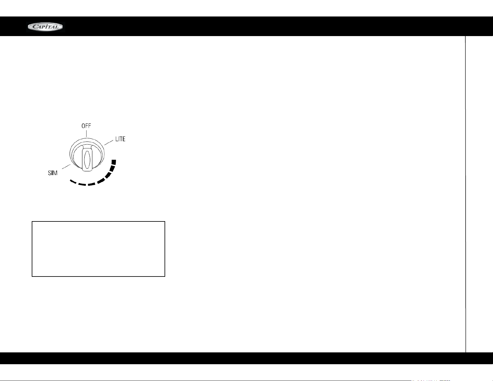
The rangetop burner valves have infinite settings and there are no fixed positions on the
control knobs between HI and SIMMER. To
turn the ranget op bu rner on, push in the
control knob and turn it count erclockwise
to the "LITE" pos ition. An audib le clicki ng
sound will be heard. When the gas has
been ignited by the electronic spark igniter,
turn the knob to the desired setting.
Note: If the Igniter continues to click after the
burner has been lit, turn the knob to a setting
other than LITE, or HI. If the problem still persists,
please call our Service Hotline at 866-402-4600.
CAUTI ON! W h en tu r nin g o n any R ANG E TO P
bur n er, b e su r e to sto p at t h e "L I TE" posi t ion
before turning th e bu rn er to a fl am e setting for
co oki ng. If the bur ne r is not li t and it is tu rne d
be yond t he "LIT E" p os iti on , to H I, MEDI UM , or
LO, there will be a burs t of flame when the burne r
does light. This c ou ld cause burns or damage t o
the surrounding counter top.
BURNER GRATES
The burner grates are a heavy cast iron. They are
designed in sections to make them easier to remove
and clean.
finer department stores, specialty cooking shops, or
restaurant supply stores. If using regular cook ware
be very careful if pans have plastic handles, as our
Culinarian burners can melt or bubble the handles.
THE CONTROL KNOBS
The cont rol knobs are readily associated with
the burners they control. The RANGETOP control
knobs are labeled in front of the bur ne rs . The
oven co ntr ol i s pl ace d sl ight ly h igh er t han the
ot her control knobs. This is due to the physical size
of the commercial type thermostats used on the
product.
CAUTION!
U s e e x t r e m e c a r e w h e n p l a c i ng t h e g r i l l
co mponent s into th e g ri ll comp artme nt . Avoid
hi tti n g th e c eramic ign ite r t hat coul d break,
preventing operation of the grill.
Do not leave the grill unattended while in use.
Do not use charcoal briquettes, ceramic plates, or
coals of any kind.
After rem ovin g all packagi ng material s, check to
be ce rtain that the gril l components a re correctly
as sembl ed in th e g ri ll box. The gril l g rates and
th e b u rne r a re ass embl ed in t he gri ll box fro m
the factory.
Note: Your grill racks are made of cast iron and
enameled
USING THE WOK RING
Wok grate is available as accessory for wok
cooking stir-fry this can be placed on any top
burner, removing the top grate and placing the
wok grate
The Culinarian Wok system is perfectly designed to
deliver high intense heat, by spreading the flame under
the diameter of the wok pan.
All the range-top burners have electronic spark ignition
to eliminate continuously burning pilots. When the main
burner flame is blown out, it will relight. Also each
burner has its own ignition module. If one module fails
all others will continue to work and you are not inconvenienced.
If a burner does not ignite, lis te n for the c li ck ing
so und . If the burn er do es no t cli ck, TURN OFF
BU RNER. Che ck the circuit breake r for a blo wn
fuse or a trippe d circuit breaker. If the ign iter still
fails to operate, please call our customer service department at 1-866-402-4600.
Note.
If you are using propane gas, a slight pop or flash may
occur at the burner ports a few seconds after the burner
has been turned "off". This "extinction pop" is normal for
propane gas.
COOKING ON THE GRILL
The burner should light within approximately 45 seconds.
Prehea t the gril l for ap pr oxi mat el y 5 minu te s
minimum. The hot grill sears the food, sealing in
the juices.
The longer the preheat time, the faster the meat
browns and the darker the brand marks.
Grilling requir es high heat f or optimum res ults.
Hi gh h ea t is nec es sa ry f or s ea ring and proper
br o wn ing . Mos t food s are co oke d at m e di u m
heat setti n g s fo r mo s t of the cook i n g ti m e .
However, when grilling large pieces of meat or
PROPER COOKING UTENSILS
For best results we recommend using Professional
Cookware. These types of utensils can be found at your
15
Page 16
USING THE RANGETOP
MCOR SERIES
poultry, it may be necessary to turn the heat to a
lower s etting after the initial browning. This
cooks the food through without burning the outside
Foods cooked for a long period of time or basted
wi t h a su g a ry ma ri n a de m a y ne e d a l ow e r
h e a t setting near the end of the cooking time.
After grilling and the food has been removed, turn the
knob to HI and burn off any excess grease that may
have accumulated on the burner. When cooled, the
grill radiants can be turned upside down and heated
on high for 10 minutes to burn off any residual fat.
Use a brass wire brush, dipped in hot water, to
loosen food particles from the grate.
When the grill has cooled, clean the drip tray and
compartment.
GRILLING SUGGESTIONS
Trim any excess fat from the meat before cooking.
FATTY MEATS increase the likelihood of flare-ups.
slits in the remaining fat around the edges at (51
mm) intervals.
Brush on basting sauces towards the end of cooking.
Add seasoning or salt after grilling. Early salting dries
out meat.
Use a spatula or tongs instead of a fork to turn the
meat. A fork punctures the meat and lets the juices
flow out.
After the juices begin to bubble to the surface, turn
the meat only once. This helps keep the juices in the
meat.
Some pieces of meat and poultry cook faster than
others. Move those pieces to the cooler area of the
grill until the rest has cooked.
The doneness of meat is affected by the thickness of
the cut. Chefs say it is impossible to have a rare
doneness with a thin cut.
GRILL RACKS
The grill racks are double sided, two position
grates, constructed of Cast Iron. Use the concave side (channels up) for meats of higher fat
content (steaks, hamburgers, sausage patties,
etc.); use the convex side (channels down) with
foods of lesser fat content (fish, vegetables,
W ARNING! D o n o t l ea v e t h e B BQ
secti o n u n a t t end e d while cooking!
16
Page 17

U S I N G T H E R A N G E T O P / U S I N G Y O U R O V E N
MCOR SERIES
HANDLING EXCESSIVE FLARE-UPS
The intense he at needed for grilling may
also cause flare-ups, due to grease and basting sauces dripping on the hot radiants.
If flare-ups occur, use a long handled spatula
to move the food to another area of the grill.
Should flare-ups become excessive, remove
the food from the grill and turn off the burner
Excessive flames occur when cooking meat
with high fat concentration, i.e. 30% ground
beef, untrimmed steaks, lamb chops, etc.
Be cautious when turning meat over, and
never PLOP the meat on the grates.
COOKING ON THE THERMO-GRIDDLE
Description:
The built i n gr id dl e is made of non rust in g
3/8" thick stainless steel. This produces a surface
that is easy to clean and never rusts.
The griddle has a aluminized steel U shape
burner that is lit by a hot surface igniter. The griddle should pre heat for five to ten minutes.
A chopping block is available as an accessory and
purchased separately. It is sized to fit on top of the
griddle surface when Range top is not in use.
The burner is rated at 18,000 BTU/HR.
CONTROL KNOB
The griddle is thermostatically controlled with tem-
peratures marked on the knob from 150 degrees F
to 500 degrees F
There are no fixed settings on the knob.
Press and turn the knob counter-clockwise to
the temperature setting.
PREPARING THE GRIDDLE
The griddle must be level or tilted slightly
forward for optimum performance. The griddle should have been leveled during installation.
PRIOR TO USE, It Is NECESSARY to wash
the griddle plate with warm soapy water then
rinsed with clear water. The griddle may be
used without butter, margarine, or oil. However, a very small amount may be used to
flavor foods.
COOKING ON THE GRIDDLE
Check that the grease tray is tucked under the
griddle plate overhang.
Turn the knob to the cooking temperature to pre-
heat the griddle.
Preheat 10-15 Minutes.
Add butter, margarine, shortening or oil for more
flavor: Add food and cook!
OVEN USE
GENERAL (Only on l arge oven).
Your large new oven can be used in 3 cooking models convection bake, regular bake, and regular broil, To help you decide which way to cook your food read this information first.
Remember this is a new oven and the thermostat has been
checked for accuracy. Your old oven had a thermostat that over
the years got a little cold. Check your recipes for the correct
time and temperature and don't use the old time or temperature
you were using to compensate for your old oven being off
temperature.
SMALL OVEN
Regular and convection bake.
BURNERS
Your new Culinarian Series— range is equipped
with bake and broil burners typical of those
used in restaurants. The oven broiler burner is
18,000 Btu/hr and the oven baking burner is
30,000 Btu/hr.
ELECTRIC GLOW IGNITER
The oven bake and broil burners are equipped with
an electric glow igniter and safety system which
lights the gas. There will be a delay after the control
knob has been turned on to when you actually hear
gas arrive at the burner. The burner will ignite after
the gas reaches the burner, sometimes this can take
as long as 45 seconds.
USING CONVECTION BAKE AND REGULAR BAKE
TO SET THE OVEN FOR CONVECTION BAKE
AND REGULAR BAKE
Decide if you are going to use CONVECTION BAKE or
REGULAR BAKE. These cooking modes are for baking
or warming: using one, two, three or four racks. If you
are going to use Regular Bake turn the oven control
knob to the temperature used in the recipe.
To use Convection Bake, simply press the
CONVECTION Button located on the front
panel to start the Convection Fan.
CONDENSATION
During any cooking process there is a certain
amount of moisture that evaporates from the
food. The amount of moisture that condenses
on the oven depends on the moisture content of
the food. The moisture will condense on any
surface that is cooler than the inside of the
oven, such as the control panel or the top of the
door.
CONVECTION BAKE
Convection Bake is baking with a fan at the back
of the oven circulating the hot air in a continuous
pattern around the food. This circulating hot air
heats and browns the surface of the food more
effectively than in a standard oven. This allows
most foods to be cooked at lower oven temperature or in less time,
17
Page 18
USING YOUR OVEN
MCOR SERIES
if baked at the regular temperature. The air is recirculated and reheated. Uncover, longer cooking
foods such as large pieces of meat or other foods
that can be cooked in low sided baking utensils or air
leavened foods, are where you will see the most savings in cooking time. Using multiple rack at the same
time will achieve a good time saving, as you can cook
more food at the same time. The number of recipes
requiring preheating of the oven is reduced considerably
because the heat reaches the food faster as the hot air
circulates around the food.
FOODS SUITABLE FOR CONVECTION BAKE
Air Leavened Foods (angel food cake, soufflés,
cream puffs, meringue shells)
Appetizers
Breads
Main Dishes
Oven Meals (1 to 4 racks)
Cookies
Pies
Po ul try
Roasts
CONVERTING RECIPES TO CONVECTION BAKE
Low sided baking utensils will provide the best results, as
the hot air can reach all sides of the utensil easier. The
oven temperature can be left the same as the recipe
and the food cooked a shorter period of time. The
temperature can be lowered 25°F to 50°F and the
food will probably take the same length of time to
cook as the recipe states. If you find that food is adequately browned on the outside, but not done in the
center, lower the temperature another 25°F and add
to baking time. When reducing the temperature always check the food for doneness, a minute or two
before the minimum time stated in the recipe, as
time can always be added. Some recipes will cook
faster than others. There is no way to predict exactly
how long each recipe will take when you convert it to
convection.
Convection will be easier to use after you have used
it a few times as you will begin to understand the way
it bakes.
SELECTING UTENSILS FOR CONVECTION BAKE
Cooking by convection does not require any specially
designed baking utensils. You probably have many
utensils in your kitchen that are suitable to use. When
choosing a baking utensil, consider the material, the
size and shape as they all affect the baking time, the
appearance of the finished product.
Metal bake ware (aluminum, steel and cast iron) all
result in the fastest cooking time and the best end
product. Aluminum pans work best for all types of
baked goods. For the best browning, use a pan with a
dark or dull finish that absorbs heat, when baking
pies and breads. A shiny finish works best for cakes
and cookies, since it reflects some of the heat and
provides a tenderer surface. Cookie sheets with only
one lip will give the best results, as the heated air can
circulate all around the sides of the food.
For roasting use bottom of the broil pan and elevate the
meat on a metal roasting rack. Glass-ceramic or glass
utensils do not conduct heat as well as metal, but they
can be used. Use them for foods that do not require a
dark brown crust or crisping, such as soufflés.
Baked items cook more quickly and evenly if they are
individually smaller in size, i.e. two or three small foods do
better than one large piece. When single food items are
baked, always center the rack. If several foods are being
baked, space them evenly on the racks.
RACK POSITIONS
One to four racks can be use d simultaneo usly
during convection baking. Place the rack(s) in the
desired position before turning the oven on. Store the
unused racks out of the oven.
Rack position 2 (second from bottom) will probably
be used the most for single rack convection baking.
When baking on more than one rack you do not
need to stagger the pans. Allow at least 1" of space
between the oven walls and the pans so the heated
air can circulate. Pans should be place d in the
center of the oven, stacked above each rack.
REGULAR BAKE
Bake is baking with hot convected air; with not fan.
The air movement comes from natural convection as
the air heats, it moves to the top of the oven. This
oven mode is the same as you have been using for
baking on one or two racks.
FOODS SUITABLE FOR BAKE
Appetizers
Pies, Cakes
B r e a d s
D e s s e r t s
Main Dishes
Oven Meals (1 to 2 racks)
Poultry
Roasts
CAUTION: Aluminum foil should never be used to
cover the oven racks or to line the oven bottom.
The trapped heat can damage the porcelain and
the heated air cannot adequately reach the food
being baked.
RACK POSITIONS
If you are using two racks simultaneously, be sure to
check the food on the bottom rack sooner than the
minimum time. The food on the lower rack position
may cook slightly faster than the food on the upper
rack, particularly if you are using large baking utensils so
that one is not directly above the other and the heated
air can circulate freely around each pan. Allow
18
Page 19
U S I N G Y O U R O V E N
MCOR SERIES
at least one inch of space between the oven walls and
the pans.
If using large or commercial size baking utensils, the
food may take a few extra minutes as the air cannot
circulate as freely as it does with a smaller pan. When
using commercial size baking utensils, use only one
GETTING THE BEST RESULTS
BAKING:
Fol low th e rec ip e amo un t and in gredi en ts ,
including the size and shape of the baking utensil
recommended in the recipe.
Do not open the oven door "just to peek," use the
interior oven light and look through the window.
Do not use the oven for storage, especially when
baking in the oven. Extra utensils, not being used
for baking, can affect the food product, baking
time, browning, and end result.
If you are using glass utensils, lower the tempera-
ture 25°F.
Use a minute timer and set it for the minimum
time suggested in the recipe.
CONVECTION BAKING
Follow the first three recommendations above.
Metal utensils give better results, in convection, than
do glass baking utensils. If you use glass, it usually is
not necessary to lower the temperature an additional
25°F.
Use a minute timer and set it for less than minimum
time suggested in the recipe. The first time you use a
recipe in the convection mode, be sure to note the
new baking time on your recipe for future reference.
Be sure to read the basic information on convection
before using the oven for the first time, page 14-16.
Keep in mind that convection baking results vary,
depending on type of product.
Notes:
HIGH ALTITUDE BAKING
Recipes and baking times vary if you are baking at high
altitude. For accurate information, write to the. Agriculture
Extension Service. Colorado State University, Fort
Collins, Colorado 80521. Specify the type of information
and the baking mode (convention bake or bake) you need,
i.e. cakes, breads, etc. There may be a cost for the bulletins.
TO USE THE OVEN ON LOW TEMPERATURE
The oven can be used to keep hot food hot, to dehydrate
food, to warm plates, for slow cooking (as in a crock pot),
and to defrost foods.
You can keep hot, cooked food at serving temperature. Set
the oven to the temperature suggested in the chart. Rare
meat must be eaten when it is removed from the oven, as
continues cooking from its own heat.
To kee p f ood mo ist , i t m ust be cov er ed wit h aluminum foil or a lid.
To dehydrate food, follow suggestions in a recipe.
To warm plates, check with the dishware manufacturer for
the recommended temperatures.
To use the oven as a low cooker set the oven control knob
to 255°F. Place the food in the oven in a pan with a tight fitting
lid. Follow recipes for this type of cooking.
To thaw uncooked frozen food, set the oven control knob
to "warm". Be sure the food is tightly wrapped in foil. Thaw
the food just enough. Cook immediately.
Do not refreeze.
To thaw frozen cooked food, set the oven knob to
170°F. Loosen the freezer wrapping. Do not use plastic wrap or wax paper in the oven.
FOOD SAFETY
According to the United States Department of Agriculture you should not hold foods at temperatures
between 40°F to 140°F for long er than 2 hours.
USING CONVECTION BROIL AND REGULAR
BROIL.
TO S ET THE OV EN FO R CONVE CTIO N
BR OI L AND REGULAR BROIL
CAUTION: Pay special attention when setting the
Oven Control Knob on "BROIL". If you set the knob
past the "BROIL" setting, the burner will not ignite.
The burner will ignite after the gas reaches the
burner. The "oven on" indicator light will come on to
let you know that the broiler is currently on. During
the broiling process, the infra-red burner produces
such an intense heat that the burner will cycle on
and off to maintain an efficient yet safe interior cooking environment.
The HEATING indicator light on the valve panel cycles
on and off with burner to let the user know when the
burner is lit. This cycling process is used to evenly
distribute and safety control the intense heat that the
broil burner produces. The cycling feature prevents
the burner from producing range-damaging heat.
RACK POSITION FOR REGULAR BROIL
The r ack p osit ion d e pen ds on t h e typ e and
th ickness of th e food. Thi ck pieces of me at or
poultry (1" or more) would typic ally be broiled
on rack position 4.
19
Page 20
USING YOUR OVEN
MCOR SERIES
Steaks chops and hamburgers would typically be
broiled on rack position 4. If top browning casseroles
or bread, the thickness of the food will indicate the
position. Casseroles and bread would typically be
browned on rack position 2 (see instructions below
for more information).
REGULAR BROIL
Broil is cooking by intense infrared radiant heat supplied by
the broil burner located at the top of the oven.
FOODS SUITABLE FOR BROILING:
Appetizers
Rack position #3 or #4
Meats, Poultry, Fish (under 1")
Rack position #4
Top Browning: Casseroles and breads
Rack position #2 or #3
NOTE: The broiler pan for both broiling and convection
broiling should be placed all the way to the back of the
oven and centered on the rack for best results.
USING A MEAT THERMOMETER TO BROIL AND
CONVECTION BROIL
To accurately determine the doneness of a thick steak or
chop (1-1/2) inches thick or more), use a meat thermometer. Insert the point of the thermometer into the
side of the meat to the center. Cook the first to 90°F for
rare meat. Cook the first side 100°F for medium to
well done. Cook the second side to the desired degree for the doneness you want, 140°F to 145°F for
rare, and 150°F to 155°F for medium and 160°F to
165°F for well done. If you are cooking pork, cook to
160°F.
A large two-piece broil pan comes with your new
range. When you are broilin g, al ways use both
pieces. Do not cover the grid with aluminum foil.
This slotted grid allows the grease drippings to flow
into the bottom of the pan keeping it away from the
intense heat of the infra-red broiler burner. This help to
minimize the smoking and spattering of the grease.
TO GET THE BEST RESULTS
OPEN DOOR BROILING
NOTE: Open Door Broiling is also possible with the
Precision Series oven. However, the oven door hinge
DOES NOT have a dedicated Broil-Stop position. To
achieve the best results for Open-Door Broiling, open
oven door approximately 6-8 Inches.
WARNING! NEVER leave pets and/or small children
unattended while oven is in the Open Door Broiling position. Front panel and knobs may get hot
to the touch as the heat is directly escaping to
the front section of the oven. Wear oven mitts
and always use Caution!
Defrost the food before starting to cook.
Put food on broiler pan, center and push broiler pan
to the very back of the oven rack.
Set a minute timer for the minimum time to check the
food.
Steaks should be at least one inch thick, if rare doneness
is desired. It is difficult to get rare with meat that is thinner.
After half the total cooking time, turn the food over only
once. It is not necessary to turn over thin foods (fillet
of fish, Ham slices, etc.). Liver slices must be turned
over.
Use a two-piece broil pan. Two-piece broil pans are
designed to minimize smoke and spatter. DO NOT
cover the slotted grid with aluminum foil. This will
catch the grease and could cause a fire.
When top browning use metal or glass-ceramic bake
ware. DO NOT use heat-proof Glass or pottery as this
type of glassware cannot withstand the intense heat
of the broiler burner. Place the vertical positioning
rod into the hole located on the bottom left side of
the oven can.
NOTE: You cannot use the broiler burner and
the bake burner at the same time. When one is
on, the other cannot be turned on!
NOTE: It is not recommended to use the convection
fan if Open Door Broiling.
20
Page 21

U S I N G Y O U R O V E N - S E L F C L E A N M O D E
INTERNAL COOKING TEMPERATURES:
FOOD OVEN TEMPERATURE
Egg and Egg Dishes
Eggs Cook until yolk and white are firm
Egg Casseroles 160 degree F
Egg Sauces, Custards 160 degree F Ground Meat
and Meat Mixtures
Turkey, Chicken 165 degree F
Beef, Veal, Lamb, Pork 160 degree F Fresh Beef,
Veal, Lamb
Medium Rare 145 degree F
Medium 160 degree F
Well Done 170 Degree F Fresh Pork
Medium 160 degree F
Well Done 170 degree F Roast Beef
Cooked Commercially 140 degree F
Vacuum Sealed 140 degree F
MCOR SERIES
Ready to eat 140 degree F
Poultry
Chicken, Turkey-Whole 180 degree F
Chicken, Turkey-dark meat 180 degree F
Poultry-breast 170 degree F
Duck and Goose 180 degree F
Stuffing
Cooked alone or in bird 165 degree F
Sauces, Soups, Gravies, Marinades
Used with raw meat, poultry, or fish Bring to boil
Seafood
Fin Fish Cook until opaque and
flakes easily with a fork
21
Page 22
SELF-CLEAN MODE/CARE AND MAINTENANCE
MCOR SERIES
All stainless steel parts of the appliance can be cleaned
with hot soapy water, rinsed, dried and buffed to a shine
with a soft, heavy pile cloth. Make sure you clean in the
DIRECTION OF THE GRAIN and never in circular
motions as this may scratch the stainless steel.
When cleaning this range or range-top:
1. Always use the mildest cleaning procedure first.
Some brands of cleaners of the same type are harsher
than others, read their directions. A scent or a propellant
can make a difference in the product. Read the ingredients. Try on a small area first.
2. To avoid marring the surface always rub metal finishes
in the direction of the polish (grain) lines. The
cleaner will be more effective when used in the direction of the polish lines.
3. Use only clean sponges, soft cloths, pa per towels, for
cleaning or scouring (Use only soap pads with soap
still in them. An empty pad can scratch), as recommended in this section.
4. Be sure to rinse all parts thoroughly and to wipe
dry to avoid water marks.
NOTE: BRAND NAMES - In this section on cleaning, the
use of name brands is intended only to indicate a type of
cleaner. This is not constitute an endorsement. The omission
of any name brand cleaner does not imply its adequacy or inadequacy. Many products are regional in distribution and can be found in the local markets and department stores.
RANGETOP
Turn of f all the burners and allow the grates to cool before starting to clean the range top. Do not clean hot surfaces.This could burn you. Clean only when the range
or Range
BURNER GRATES
When lifting the grates, be careful as they are heavy. Place
them on a protected surface, so they won't scratch the
surface they are laid on.
The burner grates are matte porcelain enamel over cast
iron. When cool they may be placed in the dishwasher, or
wipe while on the range top using hot soapy water, then
rinsed and wiped dry. The burner grates will not rust as
they are matte porcelain enamel on both sides for durability.
The occasional use of mild abrasive cleaners such as BonAmi®, Soft Scrub®. Abrasive cleansers, used vigorously
or too often, can eventually harm the enamel. Apply with
a damp sponge, rinse thoroughly and dry.
The porcelain may pop of the edge of the grates due to
rapid temperature change when the burners are turned on, Do
not be concerned as this does not result in the deterioration of
the grates. The cast iron soon darkens to blend with the porcelain
enamel. Be careful when wiping an area where the porcelain has
popped off, as the edges may be sharp.
burners clean. It is necessary to clean the burners if
they do not light even through the igniter clicks, if there
has been a severe boil over, or when the flame does not burn
blue.
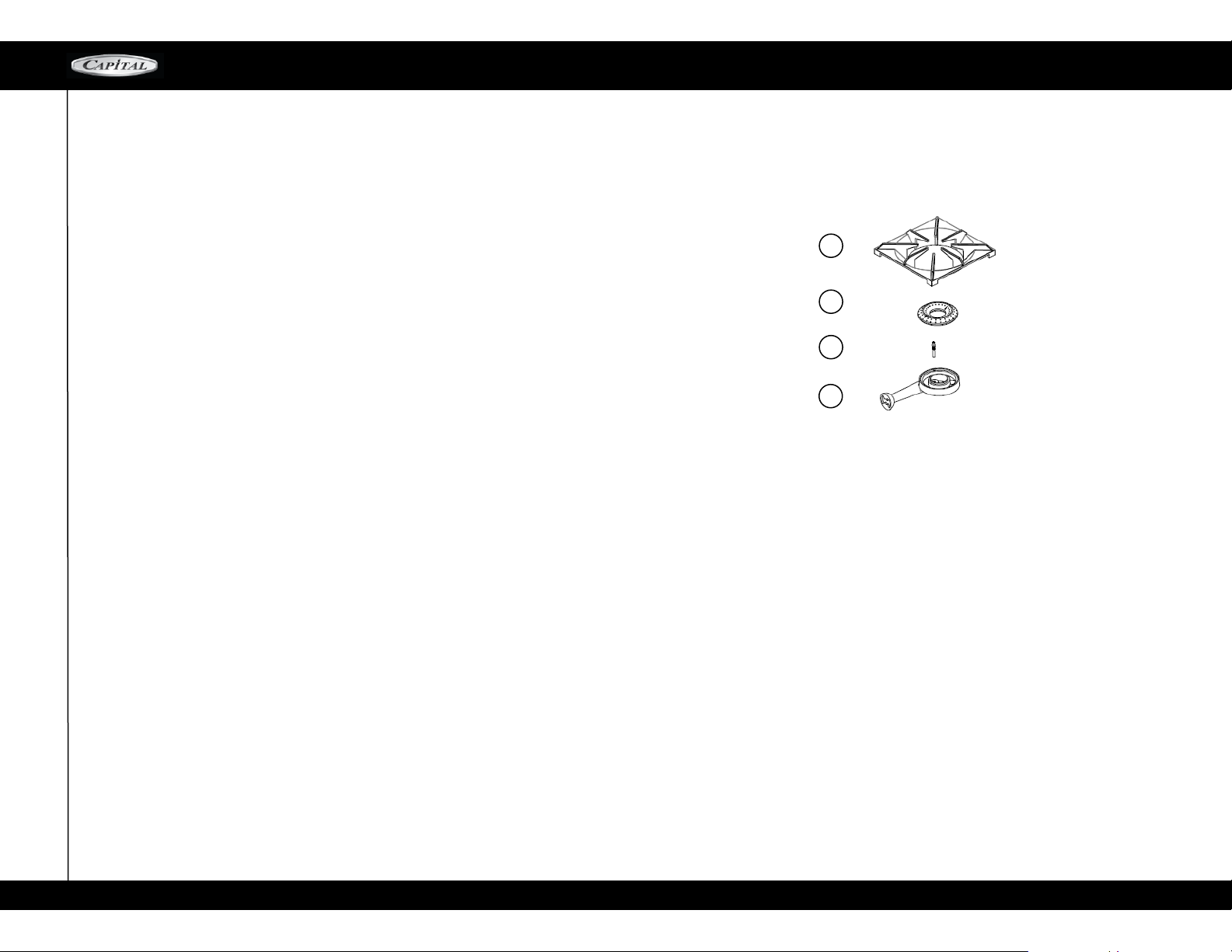
1
2
1- GRATE
3
2- Burner Head
3– Electrode
4- Burner Base
4
the grates and burners are cool, remove the grate. The
Burner Cap can easily be Remove. Wash these parts in
hot soapy water, rinse and dry thoroughly. The Burner
Caps are porcelain enamel, follow the directions on the
previous page that were given for the burner grates. A
bristle brush can be used to clean out the toothed
burner ports, if necessary.
After cleaning, it is important to make sure the Locating Notch at the bottom of the Burner Cap is properly
aligned with the Burner Base.
Incorrect alignment will produce a potentially
dangerous flame and poor burner performance
BURNERS
For proper lighting and performance keep the
22
Page 23
C A R E A N D M A I N T E N A N C E
MCOR SERIES
IGNITERS
Wipe with a water-dam pened cotto n swab. Be
careful not to damage the igniter. (See illustration).
CON TROL K NOBS - RANGETOP AND OVEN
These are made of die-cast metal with plastic inserts for
easier gripping. They can be cleaned in hot, soapy water.
To remove the Knobs from the control panel, grasp the knob
and pull straight forward. Wash, do not soak. Rinse and
dry thoroughly. It is important to replace these knobs on the
correct gas valve on the control panel.
LOW BACK, OR HIGH SHELF (IF INSTALLED)
Depending on the model, these are constructed of all
stainless steel. Use the mildest cleaning procedure
first— hot soapy water, rinse and dry. If the panel has
food soil remaining, try a general kitchen cleaner,
such as Fantastic, Simple Green®, or Formula 409.
For hard to clean soil use a stainless steel cleaner
such as, Bon-Ami®,, Carneo®,, or Bar Keepers
Friend. Apply cleaner with a damp sponge, rinse thoroughly and dry. Always scrub lightly in the direction of
the grain. Do not use a steel wool pad, it will scratch
the surface. To touch up noticeable scratches in the
stainless steel, sand very lightly with dry 100 grit emery paper, rubbing in the direction of the grain.
After cleaning use a stainless steel polish, such as
Stainless Steel Magic.
If the rear top burners are used extensively on high it is
possible for the vertical stainless steel panel to discolor
from the burner heat. This discoloration can be removed by
using Revere Ware Stainless Steel Cleaner.
OVEN AND DOOR INTERIOR
If in the event the oven door comes off track, or becomes misaligned, realignment can be achieved by
following this simple procedure:
Open the door and hold it all the way open. Close the
hinge latches. Once both hinges are locked, gently
lift the door up and partially out until the door is
evenly aligned. Evenly slide the door back into place
and check to assure the hinges rest in
the center of each door hinge roller. With the oven
door fully open, unlock hinge latches and the door is
ready to close again. Call our service technician if
you encounter difficulty.
Be sure the oven and door are cool before you start to
clean them. They are porcelain enamel coated. It is
acid resistant, but not acid proof. Therefore, acid
foods, such as vinegar, rhubarb, alcohol, citric juices or
milk, should be wiped off and not allowed to bake on.
Try mild cleaners, such as: Bon-Ami®, Ammonia,
Ammonia and water, or Soft Scrub®. Apply the
cleaner on a damp sponge or cloth. Rub lightly. Rinse
thoroughly and dry. If food has burned onto the oven
and is difficult to remove, soak the spots with a cloth
saturated with household ammonia. Allow it to soak
for an hour or two, with the door closed. The food soil
should be easy to remove with a damp soapy cloth or
mild abrasive.
Chrome cleaners, such as Soft Scrub, Cameo or Bar
Keepers Friend can be applied with a damp sponge
following package directions. Rinse and dry. Powdered
cleaners such as Bon-Ami® or Comet are applied with a
damp sponge or cloth, rubbed lightly, rinsed and
dried. Harsh Cleaners which are commercial oven
cleaners, such as Easy Off® or Dow can be used on
the racks. However, some commercial oven cleaner's
cause darkening and discoloration. Test the cleaner on a
small part of the rack and check for any discoloration
before cleaning the entire rack. Allow to stand for 15 to 20
minutes. Rinse thoroughly and dry.
FRAMES, SIDES, DOOR EXTERIOR, HEAT DEFLECTOR
These parts are made of stainless steel, follow the
directions for the Backguard (see page 28). Take
care when cleaning the door top. Do not let water or
cleaners run down the vents. If water or cleaners spill
into the vents, they may streak the glass inside the door.
DOOR GASKET
Use a general kitchen spray cleaner, such as Formula
409 or Fantastik®. Spray it and blot drywith a cloth. Do
not rub. Do not remove or damage the gasket
OVEN LIGHT BULB REPLACEMENT
For oven light bulb replacement use only a 40 watt,
120 volt appliance light bulb. These are available in
supermarkets. DO NOT use a standard light bulb in
any oven, the heat will break it.
TO REPLACE THE LIGHT BULB:
1. Be sure the oven light bulb switch is in the off
position.
2. Let the cover and the bulb cool completely.
3. Remove the light cover, Turn the cover to the left
(counterclockwise) to unscrew it.
4. Remove the burnt out bulb. Replace it with a 40
watt appliance light bulb only.
5. Replace cover. Turn circuit breaker back on, if
turned off. (See Caution below).
CAUTION: Be sure the oven light switch (see
page 8, # 11 ) is i n the OF F po si tion and the
light cover is cool. If the bulb comes loose
from its base, turn off the power to the oven at
the circuit breaker panel, before attempting to
remove the bulb base from the socket.
POWER FAILURE
The broiler a nd oven burners cannot be t urned on
during a power failure. To light the sealed top burners, turn the control knob to "lite" hold a lighted match
to the port ring. After the flame is burning all the
way around the burner, adjust the flame to the
desired height. It is nec essary to light eac h
bur ner individually. Do not light more than one
burner at a time.
23
Page 24
CARE AND MAINTENANCE / LOCATING RATING PLATE
LOCATING RATING PLATE
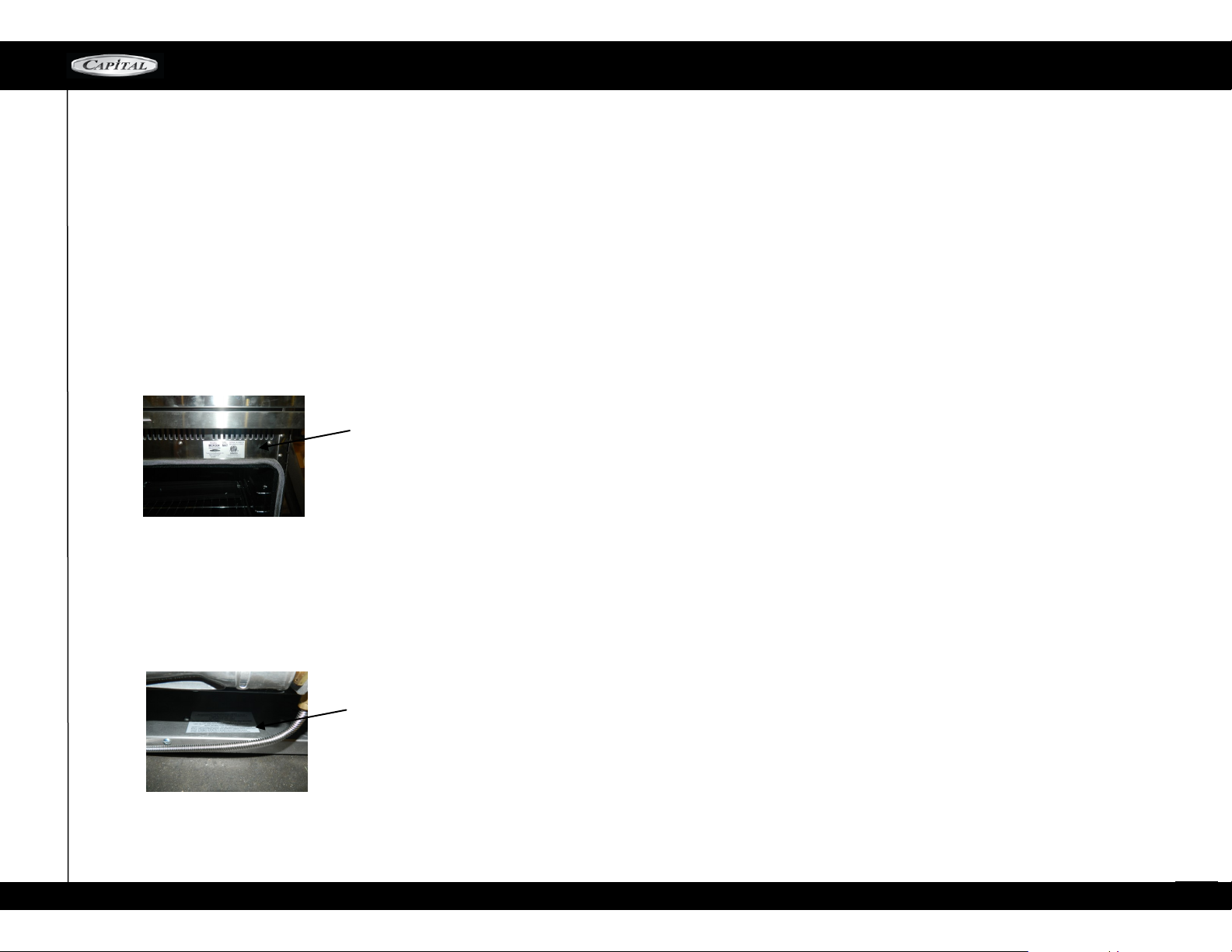
SERIAL #, MODEL # AND VERIFYING GAS TYPE
The rating plate contains necessary information regarding your range. It
provides the model #, serial # and verifies the gas type and BTU input
ratings for each burner of your appliance. When calling for service,
please have this information at hand.
The model #, serial # and gas type information is located in two places.
First, when you open the oven door, you will find a sticker that shows the
model # followed by either an N (for natural gas) or L (for LP gas), and
the serial # (see picture).
Model # , Serial# and gas type location
MCOR SERIES
The rating plate, showing the model #, serial #, gas type and gas
BTU input ratings for each burner, as well as necessary information
from ETL test labs, is located in the base of the range. You will need
to remove the kick -plate to access this information (see picture).
BTU ratings for each burner
24
Page 25
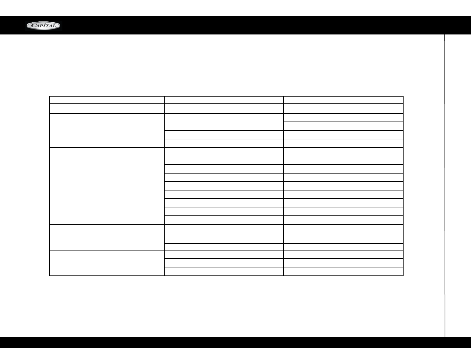
T R O U B L E S H O O T I N G
MCOR SERIES
RANGES AND RANGE-*TOP
PROBLEM POSSIBLE CAUSE PROPOSED SOLUTION
Range non-functional No electricity or gas supply
Technical Call for authorized service
One or more burners will not light No electricity Check circuit breakers
No gas Check gas supply at wall
Wrong gas type Verify gas type
Burners are dirty Clean burners ports
Incorrect flame/ sooty burner flame
BBQ-GRILL doesn't light
Burners are mis-aligned Align and reassemble burners
Water in burner(s) Dis-assemble and dry burners
Dirty electrode(s) Clean burner electrode
Technical Call for authorized service
Too large or small flame Verify gas type
Mis-aligned burner assembly Realign and re-assemble burner assembly
Bad flame See page 40-41
No Electricity Check circuit breaker
No gas Check gas supply at wall
Burner is dirty Clean burner
Turn on gas supply valve
Check circuit breakers
25
Page 26
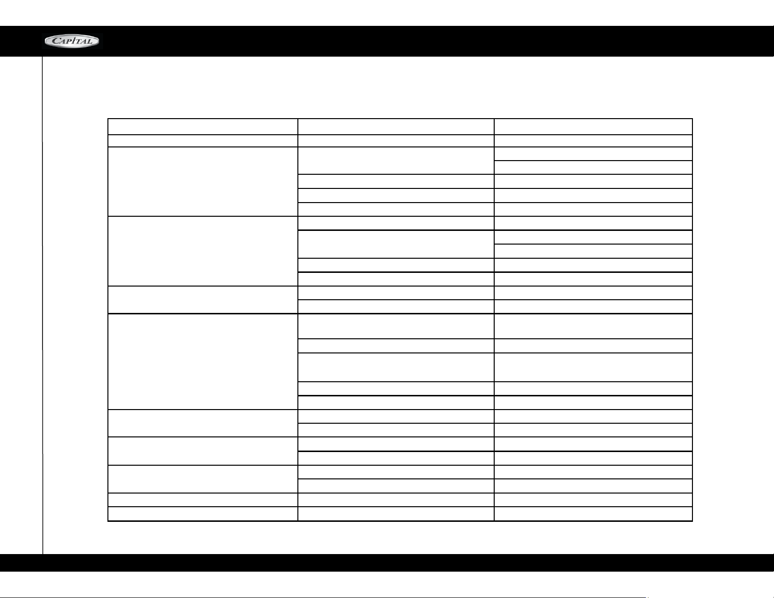
TROUBLESHOOTING
MCOR SERIES
RANGE OVENS
PROBLEM POSSIBLE CAUSE PROPOSED SOLUTION
No oven light No electricity
Loose bulb
Burned out bulb
No oven heat (bake)
No oven broil
Uneven baking
No convection
Convection noisy
Cooling fan noise
No gas Check for proper top burner operation
No electricity (check oven light)
Improper settings Verify proper settings on knob selector
Improper settings (see no bake) Verify proper settings
Insufficient pre-heat time
Improper settings Verify proper settings on knob selector
Improper utensils/placement
No convection fan Check for air movement
Technical Call for authorized service
Technical Call for authorized service
Check circuit breakers
Check plug at wall
Ensure bulb is properly screwed in
Replace bulb
Check circuit breakers
Check plug
Allow oven to preheat at least 15 minutes before
baking
Use proper utensils and place them properly in
the proper rack positions
26
Page 27

MCOR SERIES RANGES
MANUAL CLEAN CONVECTION MODELS
MCOR ( 30” 36” 48” )
INSTALLATION INSTRUCTIONS
MCOR SERIES
27
Page 28

TABLE OF CONTENTS
TABLE OF CONTENTS
Important Information 29
30" - All Models
36" - All Models
48" - All Models 32
60" - All Models 33
Unpacking and Ventilation Requirements 34
MCOR SERIES
30
31
Cabinet Install Drawing / Front View
Cabinet Install Drawing / Side View
Installation Instructions 37-38
Gas Hook-Up / Testing and Adjustments
Technician Support—Air Shutter Adjustment
How To Remove Oven Door
Cooling fan
Post-Install Check
Service & Warranty Info
35
36
39
40-41
42
43
44
45
28
Page 29
IMPORTANT INFORMATION
MCOR SERIES
PLEASE READ ENTIRE
INSTRUCTIONS
BEFORE PROCEEDING.
WARNING! If the information in this manual is
not fol l o we d exa c t ly, a fi r e o r exp l osi o n
may result causing property damage, personal
injury or death.
WHAT TO DO IF YOU SMELL GAS
Do not try to light any appliance
Do not touch any electrical switch
Do not use any phone in your building
Immediately call your gas supplier from a
neighbor’s phone. Follow the gas supplier's instructions.
If you can not reac h your gas supplier, call
the fire department.
IMPORTANT: Save these instructions for the Local
Gas Inspector's use.
INS T AL L E R: P l eas e lea v e t h e se I n sta l lati o n
Instructions with the unit for the owner.
OWNER: Please retain these instructions for future
reference.
The appliance, when installed, must be electrically
grounded in accordance with local codes or, in the
absence of local codes, with the National Electrical
Code, ANSI/NFPA 70
The appliance and its individual shutoff valve must
be disconnected from the gas supply piping system
dur ing any pressure testin g of that syst em at test
pressures in excess of 5 psi (35 kPa).
The appliance must be isolated from the gas supply
pi pin g sy ste m by cl os i ng its ind ivi dua l ma nu a l
shutoff valve during any pressure testing of the gas
supply piping s ystem at test pre ssures equal to or
less than 5 psi (35 kpa).
WA RNING! Dis co nn ect P ower be fo re installing.
Before tur ning power ON, be sure that all c ont rols
are in the OFF position.
IMPORTANT! Installation must conform with local codes.
IMPORTANT INSTALLATION INSTRUCTIONS
INTRODUCTION
Capital's CULINARIAN Series Gas Ranges are tested
and approved in accordance with ANSI Z21.1.2005,
CAN 1-1.1,M81 1995, Household Cooking Appliances. It is STRONGLY RECOMMENDED that this
appliance be installed in conjunction with a suitable overhead CAPITAL VENT HOOD Due to the high heat output of
this unit, particular attention should be paid to the hood
and ductwork
installation to assure it meets local building codes.
NOTE: Local building codes vary. Cabinet storage
above the unit should be avoided to prevent the
risk of accidental fire or burns.
In t he com m o n w ealt h of M a s s achus e t t s , g as
con n e ction m u st be pe r for m e d by a l i c ense d
plumber or gas fitter.
IMPORTANT! Installation, electrical connections,
gro unding and gas conn ections must c omply wit h
all applicable codes. In the absence of local codes,
the unit should be installed i n accordance wit h the
Na tional Fuel G as Code ANSI Z22 3. 1/ NFPA5 4 CURRENT ISSUE and National Electrical Code ANSI/
NFPA70-CURRENT ISSUE.
Be sure t he unit being in st al le d is set up for th e
type of gas sup plied. The Gas range shipp ed from
the factory is set for Natural Gas or LP (Propane),
depending on the specific model ordered.
ENSURE THAT THE RANGE IS COMPATIBLE WITH
GAS SUPPLY AT THE INSTALLATION SITE BEFORE
PROCEEDING FURTHER. Conta ct the dealer if it
is not set for the proper gas supply available at the
installation site.
IMPORTANT! A back guard must be utilized when
there is le ss than 12" horizontal clearance between
co mbustib le materia ls and the back e dg e of t he
range. The Capital CULINARIAN SERIES Low Back or
High Shelf must be ordered separately and installed at
the rear of the range. For island installations and
other installations with more than 12" clearance, our
stainless steel Island Trim is suitable to cover the
back guard mounting flanges.
GAS SUPPLY
NATURAL GAS: 6-inch wa te r col um n. (14.9m b)
Min., 8 inch (20mb) nominal
PROPANE G AS: 11-inch water column. (27.4mb),
14 inch (37mb) maximum
ELECTRIC POWER SUPPLY
MCOR30 models - 120 VAC, 60 HZ, 1 PH., 12 Amp Circuit
MCOR36 models -120 VAC, 60 HZ, 1 PH.,12 Amp Circuit
MCOR48 models -120 VAC, 60 HZ, 1 PH., 20 Amp Circuit
STEP 1: UNPACKING, MOVING and PLACING the
RANGE
CAU T I O N: Pr o per e q uipm e n t and a d equa t e
manpower must b e used in m oving the ra nge to
avo id dam age to the uni t or the floor . The unit is
heavy and rests on stainless steel legs.
It is strongly recommended that after removing the
packing material, remove the door(s), top grates,
ov en r ac ks, front kick pla te a nd d ri p pa n(s) to
facilitate lifting and easier handling.
Remo ve the outer ca rton and pack ing materials
from the shipping base. The all gas ranges are held to
the skid by three (3) bolts. After removing the bolts
the range must be lifted and removed from the skid.
Never lift the range from the oven door handle.
29
Page 30
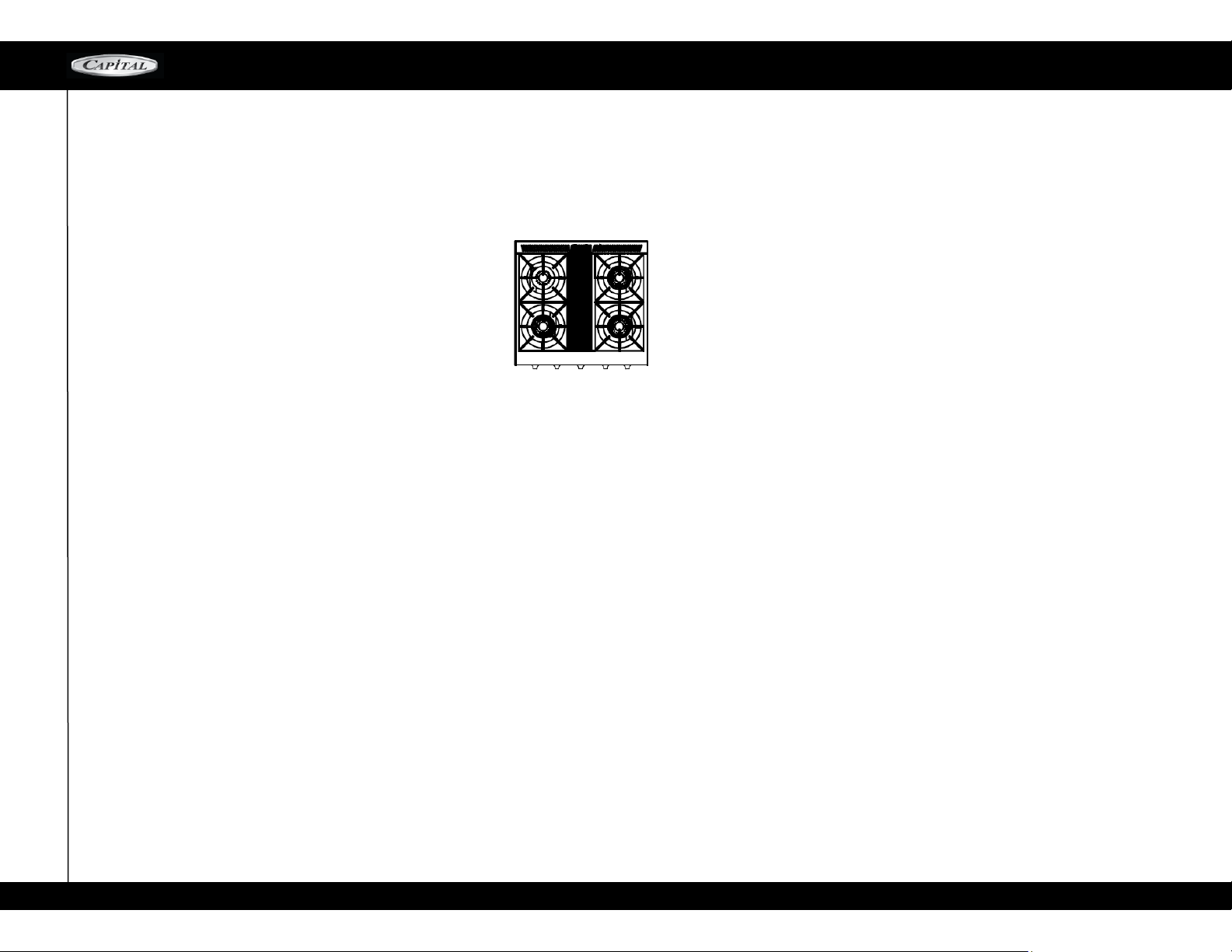
30” ALL MODELS
MANUAL CLEAN
CGMR304
four open top burners
MCOR SERIES
ALL RANGES ARE EQUIPPED WITH SMALL PAN BURNER AT THE BACK LEFT, THE OTHERS BURNERS ARE RATED AT 23,000 BTU / HR
30
Page 31
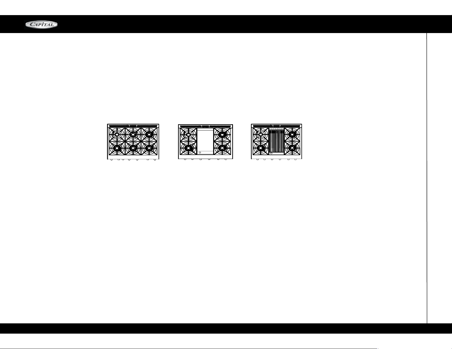
36” ALL MODELS
36” MCOR SERIES MANUAL-CLEAN MODELS
MCOR SERIES
MCOR366
ALL RANGES ARE EQUIPPED WITH SMALL PAN BURNER AT THE BACK LEFT, THE OTHERS BURNERS ARE RATED AT 23,000 BTU / HR
MCOR362G2
MCOR362B2
31
Page 32
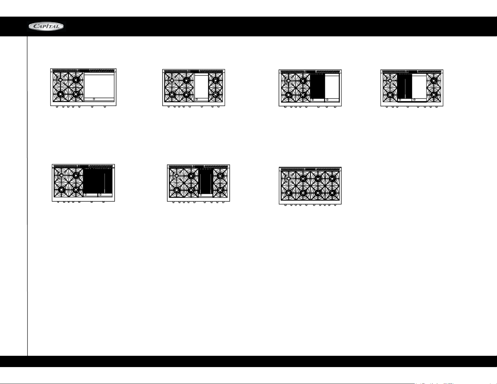
48” ALL MODELS
MCOR SERIES
MCOR484GG
Four open top burners + 24” Griddle
MCOR484BB
Four open top burners + 24” BBQ Grill
MCOR484G2
Six open top burners + 12” griddle
MCOR484B2
Six open top burners + 12” BBQ Grill
MCOR484BG
Four open top burners
+ 12” Griddle + 12” BBQ Grill
MCOR488
Eight open top burners
MCOR482BG2
Four open top burners
+ 12” Griddle + 12” BBQ Grill
ALL RANGES ARE EQUIPPED WITH SMALL PAN BURNER AT THE BACK LEFT, THE OTHERS BURNERS ARE RATED AT 23,000 BTU / HR
32
Page 33

60 ALL MODELS
MCOR SERIES
33
Page 34
UNPACKING AND VENTILATION REQUIREMENTS
MCOR SERIES
Lift the range from the skid with a soft wheel dolly.
Support the range uniformly across the bottom
To remove door, open the door completely, close
the hinge latches and release the door. Remove
door by lifting and pulling from the sides.
Make sure gas and electric connections are made,
anti-tip device is installed, and the back guard
installed prior to placing the range in position.
Measure the height of the counter top and adjust
the range height to match countertop height by
adjusting front and rear leveling feet.
Slide the range in place and ensure that the range
is level.
Reinstall the kick plate, top grates, oven door(s),
drip pan tray(s), and make sure burner caps are
seated firmly located into position.
WARNING: DO NOT lift the range by the oven
door handles, Do not remove the griddle and
grill sections!
STEP 2: VENTILATION REQUIREMENTS
It is strongly recommended that a suitable CAPITAL
exhaust hood be installed above the range. Downdraft
ventilat ion sho uld N OT be used. The tabl e bel ow
indicates the PRECISION Series Hoods, by model number, that are recommended for use with all ranges.
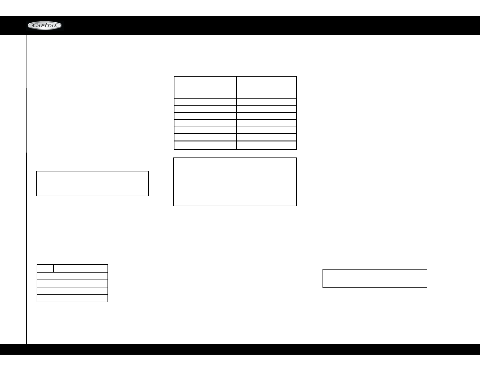
1. SELECT HOOD AND BLOWER MODELS:
SIZE SHIPPING WEIGHT
30" 400
36" 450
48" 630
60" 800
For wall i ns ta ll ations, the hood width mu st , at a
minimum, equal the width of the range's cooking
su rf ac e. W here space permits, a hood larger in
width than the cooking surface may be desirable for
improved ventilation performance.
VENTILATION UNIT STANDARD COUNTER
INSTALLATION
RECOMMENDATIONS
HOOD
BLOWER CFM's
60" RANGE = 1200 CFM
48" RANGE =1200 CFM
36" RANGE =1200 CFM
30" RANGE = 600 CFM
(2 4" D EE P X UNIT WIDTH)
CA UTIO N: V entil atio n hoo d s and blow e rs a r e
d e s i gn ed f o r u se w i t h sing l e wa ll du c t in g.
However, some local building codes or inspectors
may require double wall ducting. Consu lt local
bu ilding codes and/or lo cal age ncies , befor e
starting, to assure that hood and duct installation
will meet local requirements.
CAPITAL Hood blower speeds are variable to reduce
noise a nd l o s s o f h e a t e d o r a i r -c o n d itioned
ho use hold ai r whe n maxim um ve nt ila tio n is not
req uired. Normally the maxim um blower speed i s
only required when using the grill section.
2. HOOD PLACEMENT:
For best smoke el imination, the lower ed ge of the
ho od s hould be ins talle d a m inimum of 30" t o a
maximum of 36" above the range cooking surface.
STEP 3: CABINET PREPARATION
1. The ran ge is a f reest an di ng uni t. If the unit is
to be placed adjacent to cabinets, the clearances
shown in fig. 1 are required. The same clearances
appl y to i s l a nd i n s t all a t i ons , e xcep t for t h e
overhead cabinets, which must have a space wide
enough to accept a suitable flared island hood, as
indicated in fig. 1. Note: Capital does NOT
offer an island style ventilation hood at this
times.
2. Th e maxi m u m de p t h of ov e r h e a d c ab i n ets
installed on either side of the hood is 13".
3. A 30-inch minimum clearance is required between
t h e t o p o f t h e r a n g e a nd t h e b o t t o m o f an
unprotected cabinet.
4. Any openings in the wall behind the range and in the
floor under the range must be sealed.
5. W h e n t h e r e i s l e s s th a n 1 2 " h o r i zo n t al
clearance b etween co mb ustible m at erial D and
th e back ed ge of the rang e ab ove the cookin g
surface, a C a p i t a l L o w B ack o r H i g h Shel f
bac k g uar d m u st be ins t a lle d ( see F i g. 2A) .
When cle ar anc e to combu stibl e m at eri al D is
ov er 12 ", a C ap i tal Isl and T rim m ay be us ed
(S ee Fi g. 2B). Figu re s 2A an d 2B indic at e the
space required for each type of back guard.
6. Always keep appliance area clear and free from
combustible materials, gasoline, and other
flammable vapors and liquids.
7. Models with open broiler, noncombustible
material is to be installed on the underside of
a cabinet located above the broiler section or
unit in accordance with local codes, or in the
absence of local codes, with the National
Fuel Gas code, ANSI Z223.1/NFPA.54
WARNING: DO NOT obstruct the flow of
combustion and ventilation air to the unit.
PLEASE NOTE:
In the Commonwealth of Massachusetts, gas
connection must be performed by a licensed
plumber or licensed gas fitter.
34
Page 35
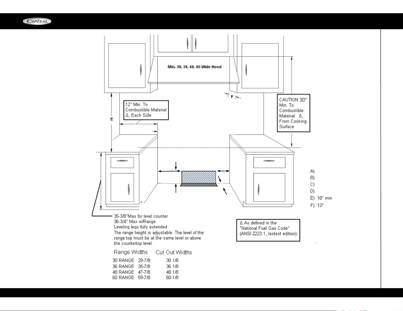
FIG 1A. Cabinet Clearances:
CABINET INSTALL DRAWING / FRONT VIEW
ELECTRICAL AND GAS
SUPPLY
A
C
B
D
MCOR-SERIES
10”
4”
10”
2-1/2”
min
35
Page 36
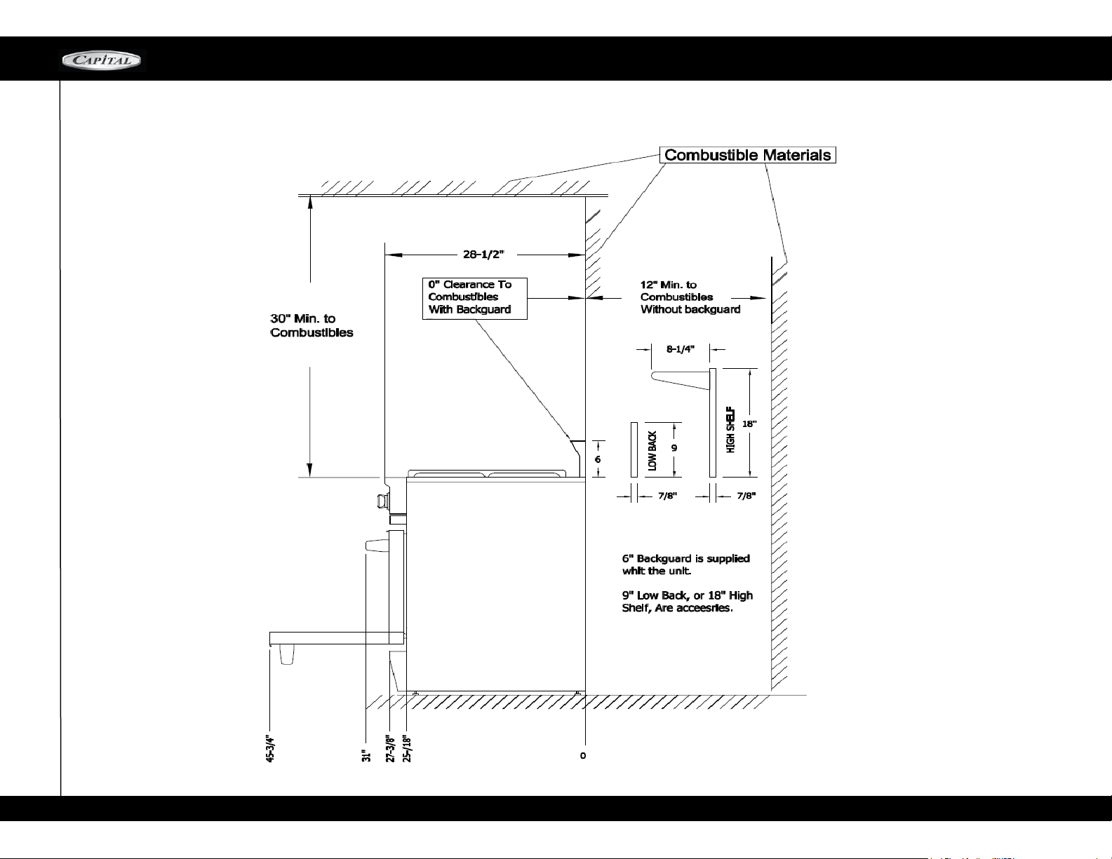
FIG 2
CABINET INSTALL DRAWING / SIDE VIEW
MCOR-SERIES
36
Page 37
INSTALLATION INSTRUCTIONS
MCOR-SERIES
NOTE:
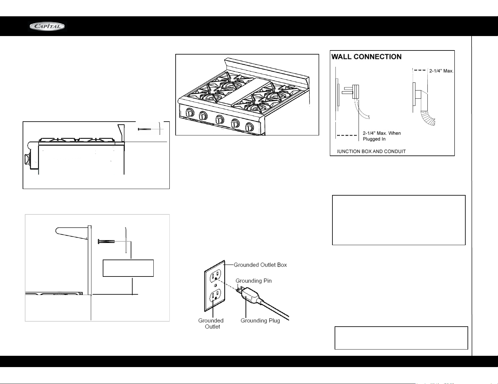
ALL MCR-SERIES RANGES Are provided with 3” Back
Guard.
1. For 6” Secur e b ot h B racke ts to th e wal l u sin g
th e screws included. 4-7/16” from the Back Trim sur-
face to the center of hole of Bracket. see Fig-1
2. For Low Back & High Shelf Accessories. see Fig-2.
Fig-1
Fig-2
Fig-3
ELECTRICAL SUPPLY, ALL RANGES
I nstalla t i o n o f A l l MCR r a n g es m u s t be
planned so tha t the rough -i n of the junction b ox
for the receptacle or conduit connection allows for
maximum clearance to the rear of the unit.
This is especially critical if the junction box in the
wal l i s dire c t ly be h ind th e j u ncti o n b ox o f t h e
unit when the u nit is installed. To minimize bi nding
wh en t he unit is connecte d to the rece pt ac le or
jun c tio n bo x, ori e n t the rec e pta c le or con d uit
connector, and slide back into position.
POWER REQUIREMENTS: 120VAC, 60 HZ single phase
30" Range – 7 Amps. Max.
36" Range – 7 Amps. Max.
48" Range – 15.5 Amps. Max.
60" Range not available in LMCR series of Ranges
CAUTION! Disconnect the electrical suppl y cord
from the w all outlet before servicing th e range.
Follow all governing codes and ordinances when
gro und i ng. In th e abs e nc e o f c ode s fol l ow the
Na tio nal E lec tri cal Code s AN S I / N FPA No. 70
(current issue).
16-3/8” For High
Shelf
GROUNDING METHOD
The range is factory fitted with a po wer suppl y and
cord with a three-p rong grounding plu g. It m ust be
plugged into a matching grounding type receptacle
c o n n ec t e d to a co r r e c t l y p o l a r i z e d 12 0 V o l t
circuit. If the circuit does not have a grounding type
receptacle, it is the responsibility of the installer to
have the existing receptacle changed to a properly
gro unded an d pola rized receptacle in ac cordance
with all applicable local codes and ordinances. The
receptacle replacement shall be in accordance with
the national Electrical Code.
WARNING! The third prong SHOULD NOT, under
any circumstances, be cut or removed!
37
Page 38
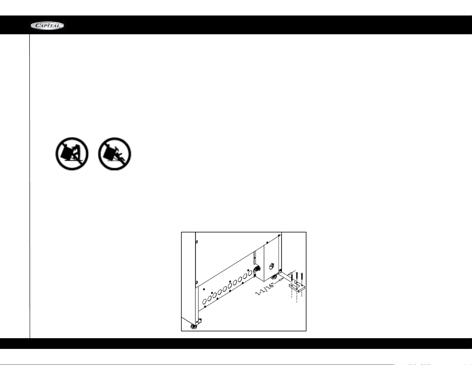
INSTALLATION INSTTRUCTIONS
MCOR-SERIES
STEP 4: INSTALLING ANTI-TIP DEVICE
For all Ranges, an anti-tip device MUST be installed as
per these instructions.
WARNING!
ALL RANGES CAN TIP
INJURY TO PERSONS COULD RESULT
INSTALL ANTI-TIP DEVICES PACKED WITH RANGE
SEE INSTALLATION INSTRUCTION
WARNING: RANGE TIPPING HAZARD!
All ranges can tip and injury can result. To prevent
accidental tipping of the range, attach it to the floor,
wall or cabinet by installing the Anti-Tip Device supplied.
A risk of tip-over may exist if the appliance is not in-
stalled in accordance with these instructions.
If the range is pulled away from the wall for cleaning,
service or any other reason, ensure that the Anti-Tip
Device is properly re-engaged when the range is
pushed back against the wall. In the event of
abnormal usage (such as a person standing, sitting,
or leaning on an open door); failure to take this precaution can result in tipping of the range. Personal
injury might result from spilled hot liquids or from the
range itself.
WARNING: ELECTRICAL SHOCK HAZARD!
Use extreme caution when drilling holes into the wall
or floor. There may be concealed electrical wires
located behind the wall or under the floor.
Identify the electrical circuits that could be affected by
the installation of the Anti-Tip Device, then turn off
power to these circuits.
Failure to follow these instructions may result in
electrical shock or other personal injury.
CAUTION: PROPERTY DAMAGE!
Contact a qualified installer or contractor to deter-
mine the proper method for drilling holes through the
wall or floor material (such as ceramic tile, hardwood,
marble, etc.)
DO NOT slide range across unprotected floor.
Failure to follow these instructions may result in damage to wall or floor coverings.
TOOLS NEEDED FOR INSTALLATION OF ANTI-TIP
DEVICE!
1.Screwdriver, Phillips
2.Drill, electric or hand
3.Measuring tape or ruler
4.1/8" drill bit (wood or metal wall or floor)
5.3/16" anchors, drywall, or concrete, 2 each (not required if mounting bracket is being attached to solid wood
or metal.
6.Hammer
7.Pencil or other marker
IMPORTANT INSTALLATION INFORMATION
The Anti-Tip Bracket may be attached on the floor.
See Bottom drawing.
The thickness of the wall or floor may require use of
longer screws, available at your local hardware store.
In all cases at least one (1) of the bracket mounting
screws must be fastened to solid wood or metal on
each side.
Use appropriate anchors when fastening the mounting
bracket to any material other than hardwood or
metal.
MOUNTING ANTI-TIP BRACKET:
The alternative floor mounted bracket shall be installed
as follows:
Place bracket on floor in position shown in Figure below.
Secure to floor or wall stud.
Later, when unit is installed, the adjustable leg will slide
under the bracket
ST EP 5: G AS CO NNE C TI ON AND HO OK-U P
Verify the type of gas being used at the installation site
matches the gas type of the range. As shipped from the
factory, units are configured for use with Natural Gas or
Propane (LP). Make certain the range matches the type
of gas available at the location.
For installation of the appliance at high altitude, please
consult your local gas company for their recommendation of the correct orifice sizes and any other necessary
adjustments that will provide proper gas combustion at
specified altitudes.
NOTE: Capital DOES NOT supply ranges to match varying altitudes. Orifices to adjust for combustion for differing altitudes may be purchased through Capital
Cooking Equipment by calling our Parts Department
at 1-866-4024600, or email us at customerser[email protected].
38
Page 39
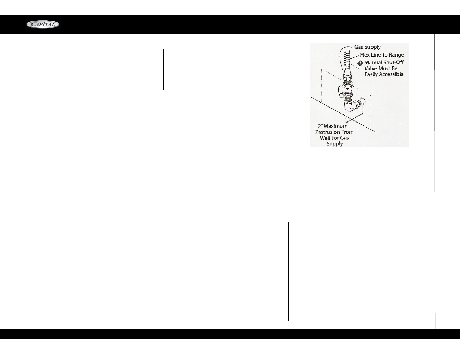
GAS HOOK-UP / TESTING AND ADJUSTMENTS
MCOR SERIES
CAUTION! W hen connecting unit to Propane (LP)
ga s. Make cert ain t h e pro pan e t ank i s e qui ppe d
with its own high -pressure regulator in addition to the
pressure regulato r supplied with the appliance t he
pressure & the gas supplied to the appliance regulator
must not, e xc eed 14" (37 mb) water co lumn.
NATURAL GAS REQUIREMENTS:
Inlet Connection: 1/2" N.P.T.
Min. 5/8" Dia. Flex Line.
Supply Pressure: 6" to 14" W.C.
PROPANE (LP) GAS REQUIREMENTS:
Inlet Connection: 1/2" N.P.T.
Min. 5/8" Dia, Flex Line.
Supply Pressure: 11" to 14" W.C.
A Regulator is required at the LP source to provide
a maximum of 14" W.C. pressure to the range
regulator.
WARNING! Gas line cannot be run inside back
cover of range. Run gas line in channel in back
of range.
HOOK UP
A manual shut off valve must be installed external to
the range in an accessible location from the front for
shutting off the gas supply when required.
The supply line MUST NOT protrude beyond the
back of the range.
Ensure that the gas supply is turned OFF at the
external shut-off valve before connecting the range.
The gas supply connection must be made by an
experienced technician and in accordance with
local codes or ordinances. In the absence of local
codes or ordinances, please refer to National Fuel
Gas Code ANSI Z223.1 / NFPA54-Current Issue.
The range is supplied with its own pressure regulator
that has been permanently mounted to the range body.
Use 5/8" diameter flex line to connect between the
gas supply and the appliance manifold pipe, which
exists at the upper left rear of the appliance. The
appliance manifold pipe connection is 1/2". Use
caution to avoid crimping the 5/8" flex line.
NOTE: the flex line for the gas supply must be
metal and approved by an approved certifying
agency (AGA, CGA, CSA, UL or CUL). NEVER use
a hose made of rubber or other synthetic material
as the heat may cause the hose to melt and develop leaks, thus causing fires, physical and property damage.
Always use pipe dope or Teflon tape on the pipe
threads, and be careful not to apply excessive pressure when tightening the fittings.
Leak testing of the appliance shall be in accor-
dance with the manufacturer's instructions.
Turn on gas and check supply line connections for
leaks using a soap solution. Never use a flame of
any sort to test for leaks.
CAUTION! The appliance must be isolated from the
gas supply piping system by closing its individual
manual shut-off valve during any pressure testing
of the gas supply piping system at test pressures
equal to or less than 1/2 psig (3.5kPa.).
The Appliance and its individual shut off valve
must be disconnected from the gas supply piping
system during any pressure testing of the system
at test pressures in excess of 1/2 psig (3.5kPa.).
When checking the manifold gas pressure, the inlet
pressure to the regulator should be at least 6.0".
DO NOT attempt any adjustment of the pressure regulator.
TESTING AND ADJUSTMENTS
Install any loose components, such as burner caps and
grates, oven racks that may have been removed earlier to
facilitate moving the appliance. Be certain that burner
caps seats properly into the alignment slots in the burner
bases. Before testing operation of the appliance, verify that
the unit and the gas supply have been carefully
checked for leaks and that the unit has been connected
to the electrical power supply. Turn the manual gas shutoff valve to the open position. Check the operation of
the sealed gas burners by pushing and turning each
knob counterclockwise to "Hl". The burner igniters will
click until the flame ignites. Burner flam es should be
BLUE and stable with no yellow tips, excessive
noise, or lifting of the flame from the burner. If any of
these conditions exist, check that the air shutter (grill
and griddle only) or burner ports are not blocked or
clogged. Remove any blockages that exist. If the flame is
too yellow, indicating insufficient air, adjust the shutter
counterclockwise to increase air inlet (grill and griddle only).
The open top burner flames should be approximately
1" to 1-1/4" High.
CAUTION ! A q ual if ied tec hn ici an m ust ma ke
burner adjustments at the ti me of instal lation.
Improper or lack of adjustments may cause harmful
by-products or void your warranty!
39
Page 40
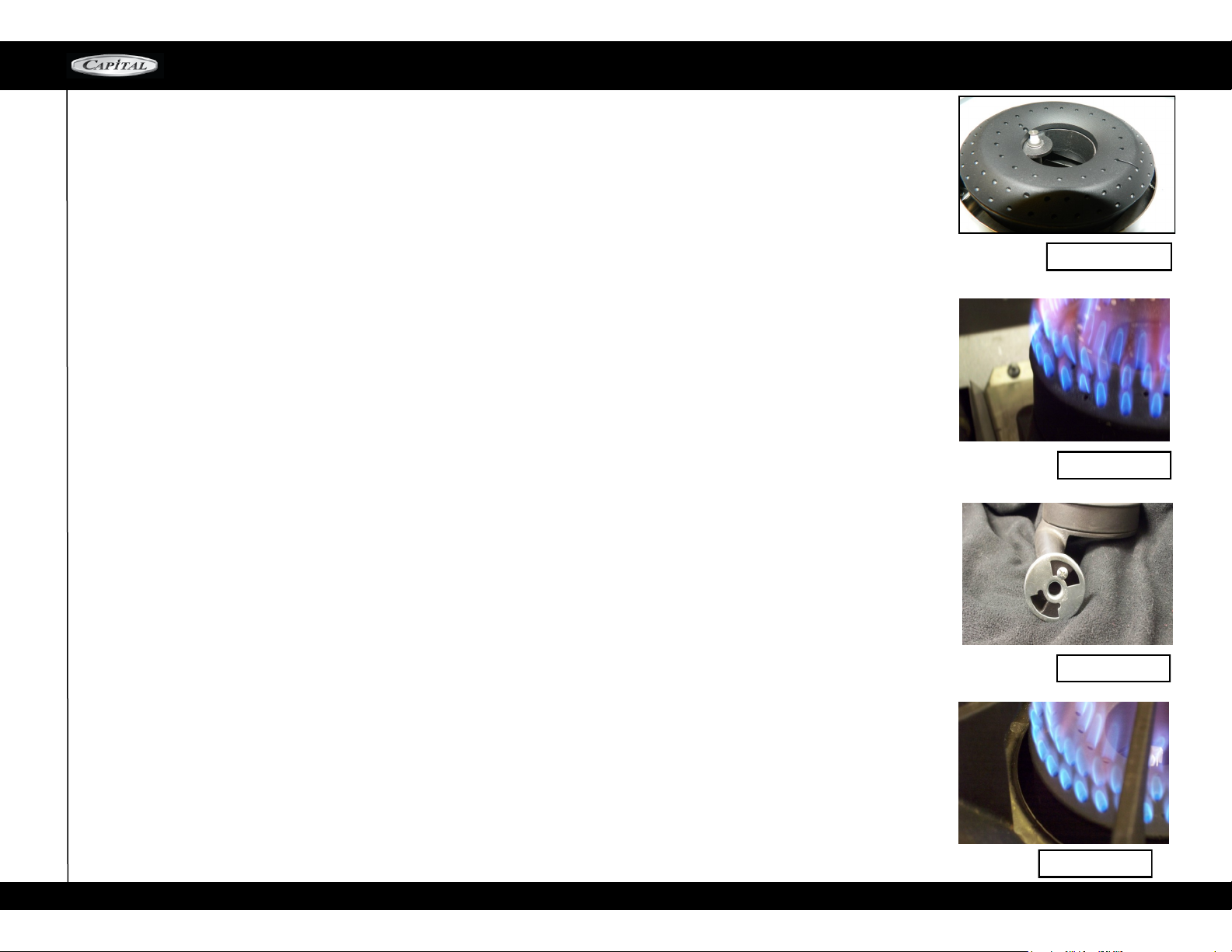
TECHNICIAN SUPPORT—AIR SHUTTER ADJUSTMENT
MCOR SERIES
CULINARIAN BURNER FLAME ADJUSTMENT PROCEDURE
PREPARATION
1. For safety purposes, turn off power and gas to the range while removing and installing the burner parts.
2. Turn off all ventilation hoods, heating & air conditioning, and close windows near the appliance to prevent breezes
from interfering during adjustment.
3. Carefully clean the metal tip of the igniter electrode with alcohol and a lightly abrasive cleaning pad or toothbrush. Dry
thoroughly.
AIR SHUTTER ADJUSTMENT
1. Correct air shutter adjustment is required prior to further adjustments. You will need a screwdriver (Flat or Phillips
head) to make this adjustment.
2. Turn power ON to the appliance.
3. Turn the burner on HIGH. All flames should have a sharp blue cone which just touches the burner. If flames are lifting
above the burner base, if the flames do not immediately ignite all around the burner, or if flames are yellow or are not a
sharp cone shape follow the procedure below.
4. Lifting Flames:
a. Turn the burners off and remove all burner grates and spill pans.
b. Using a screwdriver, loosen the screw securing the air shutter.
c. Close the opening of the air shutter slightly.
d. Turn the burner On and check the flame for lifting.
e. Adjust the air shutter until the flame is a solid blue cone touching the burner. Some orange in the large flame
corona above the burner is normal.
f. If flames do not immediately ignite all around the burner, readjust the air shutter and retest.
g. Tighten the screw on the air shutter then reassemble the spill pans and grates.
5. Yellow tipping or weak flames
a. If the flames have bright yellow tips (like a candle) or the flames are weak and flutter easily at the base, more air
is required.
b. Using a screwdriver, loosen the screw securing the air shutter.
c. Open the opening of the air shutter slightly.
d. Turn the burner On and check the flame.
e. Adjust the air shutter until the flame is a solid blue cone touching the burner. Some orange in the large flame
corona above the burner is normal.
f. If flames do not immediately ignite all around the burner, re-adjust the air shutter and retest.
Igniter Electrode
Flame Lifting
Air Shutter
Good Flame
40
Page 41
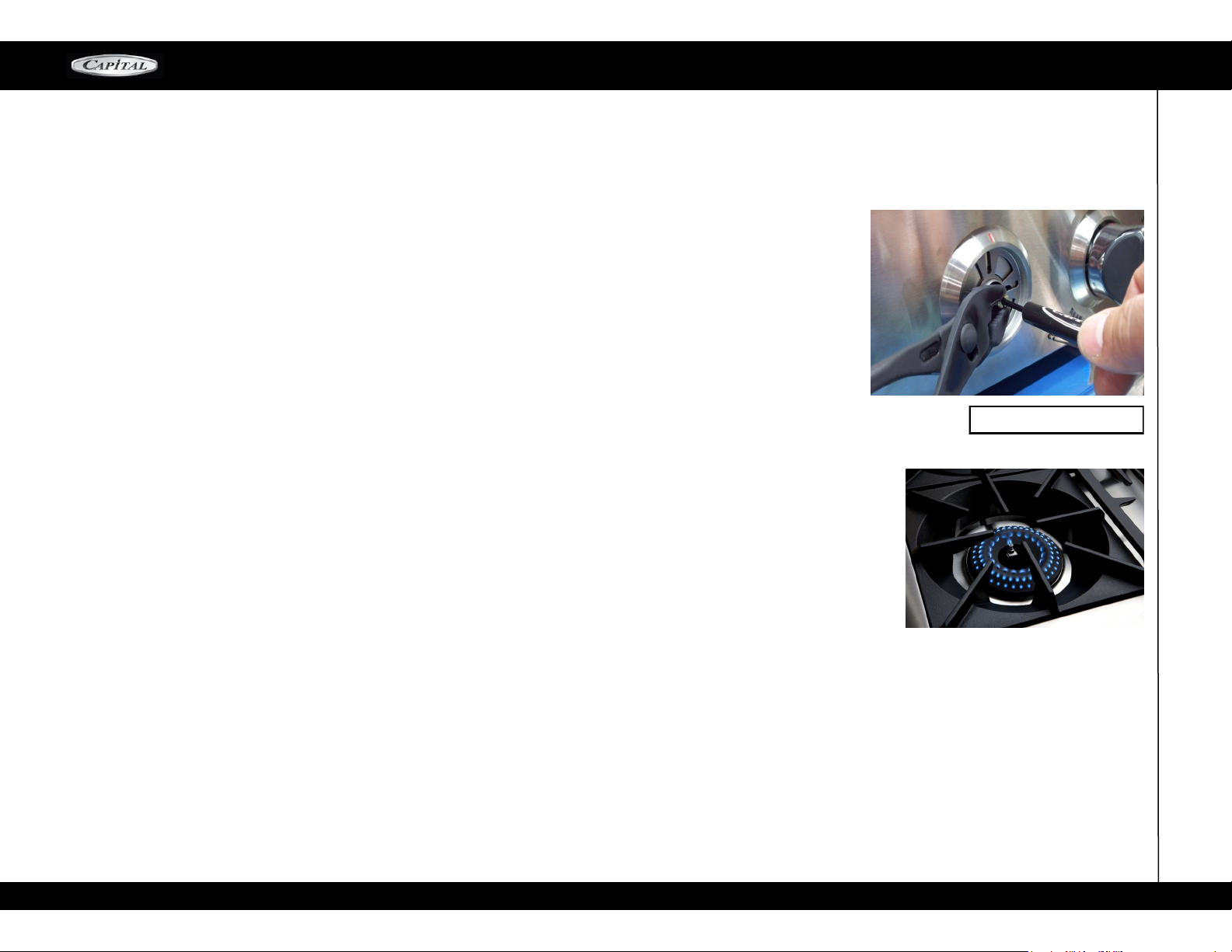
CULINARIAN BURNER FLAME ADJUSTMENT PROCEDURE
ADJUST SIMMER FLAME
1. To adjust the simmer flame you will need a flat head screwdriver with a 3/32” maximum diameter shaft
and a length of at least 2-1/4” and pliers.
2. IMPORTANT: Turn off air conditioning, fans, and ventilation hoods and close windows to prevent
breezes around the burners when making these adjustments. They can affect burner function.
3. Set the burner to be adjusted to Simmer. Remove the knob by carefully pulling the knob straight out.
4. Place the flathead screwdriver into the hole in the center of the shaft behind the knob.
5. Very lightly turn the screwdriver until you feel it seat into the screw head at the back of the shaft.
6. To reduce the Simmer flame hold the shaft with pliers to prevent it from turning then slowly turn the
screwdriver Clockwise. The flame will begin to reduce in size.
7. Turn the screwdriver until the burner starts to click or flames begin to extinguish on several holes of
the burner.
8. After the burner begins clicking or several flames extinguish on the burner, turn the screwdriver slowly
counter clockwise until the burner stops clicking and flames are present in all holes of the burner.
TECHNICIAN SUPPORT—AIR SHUTTER ADJUSTMENT
MCOR SERIES
Simmer Adjustment
9. Place a pot or pan with a small amount of water on the grate and check for clicking. Re-adjust as necessary.
10. IMPORTANT: Flames should be present on all holes of the burner and should be the size of a match
head after adjustment. If the flames cannot be adjusted lower without clicking please contact Capital
Cooking Service at (866) 402-4600.
41
Page 42
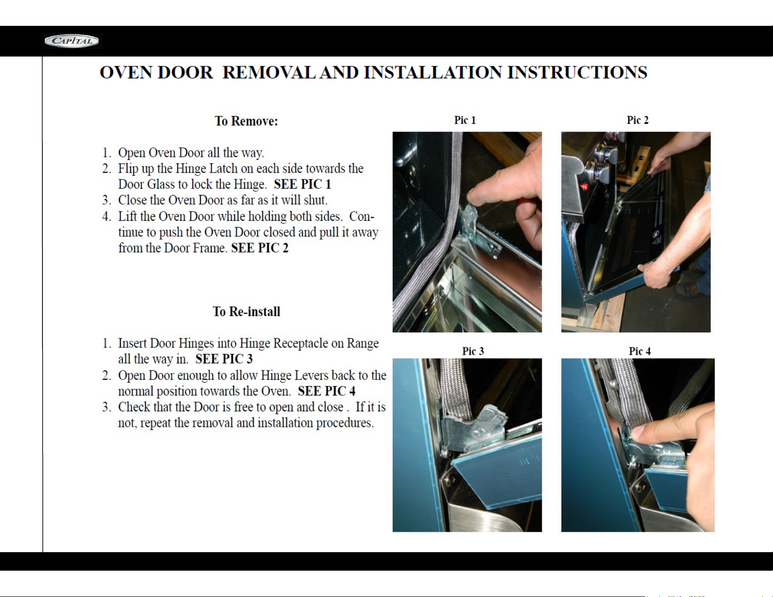
HOW TO REMOVE THE OVEN DOOR
MCOR SERIES
42
Page 43
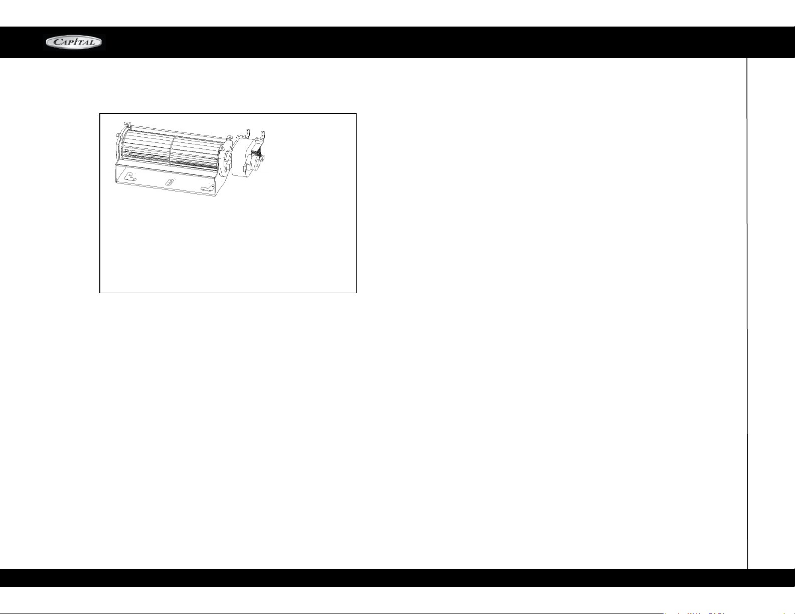
COOLING FAN
COOLING FAN
The range is equipped with a cooling system to protect electronic components from excessive heat.
There will times that you will hear the cooling system
cycling on and off while cooking. This is normal and
can continue after the range is turned off.
MCOR SERIES
43
Page 44
POST-INSTALL CHECK
MCOR SERIES
INSTALLER CHECKLIST
FINAL CHECKLIST
Placement of unit
Specified clearances maintained to cabinet surfaces
Unit Level – front to back – side to side
Burner caps and retention rings positioned properly on sealed
burner bases
All packing materials removed
Island trim or back guard attached (if horizontal
c lear anc e t o c o m bus t ible m a ter i als be hin d cooking
surface is less than 12")
Check door adjustment and hold down brackets
GAS SUPPLY
Connection: 1/2" NPT with a minimum of 5/8"
Diameter flex line
The appliance is connected only to the type of gas for which it is
certified for use
Manual gas shut-off valve installed in an accessible location (without
requiring removal of range)
Unit tested and free of gas leaks
Gas supply pressure does not exceed 14" (37 mb) W.C.
ELECTRICAL
Receptacle with correct over current protec-
tion is provided for service cord connection
Proper ground connection
Proper polarity at receptacle
Kick Panel in place and 3 screws secure.
OPERATION
All internal packing materials removed. Check
below grates and grill pans and inside the ovens
If used on Propane gas, verify that the propane
gas supply is equipped with its own high-pressure
regulator in addition to the pressure regulator supplied with appliance.
Burner caps properly seated into burner bases.
Grill Components properly seated (not all models).
Bezels centered on burner knobs and knobs turn
freely.
Each burner lights satisfactorily, both individually
and with other burners operating
Air shutter adjustment for proper flame made for
Grill and Griddle sections.
Griddle is level and does not rock.
Oven door hinges seated and hinge locks in proper
position. Door opens and closes properly.
Burner grates correctly positioned, level and do not
rock.
Note to Customer.
Please make sure installer signs each item on this
checklist, explains each item before leaving and explains the range operation to you thoroughly.
44
Page 45

SERVICE & WARRANTY
MCOR SERIES
WARRANTY
ONE (1) Year full parts and labor covers entire product with the
exception of painted or decorative parts listed below*. (Light bulbs
covered for 60 days after installation). Standard shipping only. Ex-
pedited shipping will be at customer expense.
*Painted and decorative parts will be warranted for 90 days from
date of original purchase. Any damages or defects must be
reported within this timeframe. Replacement painted parts may
have slight color variations from the original parts due to normal
manufacturing variables.
FIVE (5) Years limited part replacement warranty. Covers part re-
placement, as noted below, due to malfunction during normal opera-
tion.
Ranges*, Range Tops*, & Ovens*: All Burners**, Heating Ele-
ments, Grates*, Griddle Plates, & Oven Racks
Barbeques: Gas Valves & all burners (excluding infrared burners)
Parts will be provided at no cost to the owner with proof of pur-
chase. All other expenses, such as labor and freight, will be
the responsibility of the owner
*Excludes Porcelain Enamel Coating for ovens and grates. Porce-
lain enamel is prone to wear over time and use.
**Unless covered by LIFETIME warranty
LIFETIME warranty (non-transferable) on stainless steel sheet metal
body parts, and Outdoor stainless steel tubular barbeque
burners (excludes Professional and Pro series), against corrosion
(excludes stainless steel barbeque grates and coverage for
neglect, abuse, damage, normal heat discoloration). Proof of pur-
chase required (freight not included).
WILL PAY FOR:
All repair, labor, and parts found to be defective due to
materials or workmanship for one (1) full year are covered
by Capital’s “In
Home” warranty. This does not apply if the unit was sub-
jected to other than normal household use. An Authorized
Factory Service
Agent must provide service during normal working hours.
No charges will be made for repair or replacement at the
location of
original installation. No charges will be made for defective
factory parts returned pre-paid, through the dealer, and
claimed within the
warranty period. All claims, regardless of warranty or nonwarranty, must be documented with photos and a detailed
description
and/or narrative of the problem and submitted to Capital’s
service department.
Warranty replacement of parts for the first year will be
freight prepaid by Capital and shipped regular ground.
Requests for expedited
shipments must be paid by the customer. Capital Cooking
will not be liable for additional transportation costs, labor,
costs, taxes or
export/import duties. This warranty shall not apply, nor can
we assume responsibility for damage that might result
from failure to
follow the manufacturer’s instructions or local codes where
the appliance has been tampered with or altered in any
way or which, in
the judgment of Capital, has been subjected to misuse,
negligence, or accident. Implied warranty shall not extend
beyond the
duration of this written warranty. This warranty is in lieu of
all other warranties, expressed or implied and all other
obligations or
liability in connection with the sale of this product.
WILL NOT PAY FOR:
Installation or start-up.
Shipping damage that is not a direct result of packaging (for example freight handling).
Service by an unauthorized agency
Use of unauthorized parts.
Service during hours other than normal working hours.
Improper installation.
Service visit to teach you how to operate the appliance,
correct the installation, reset circuit breakers or
replace fuses.
Repair other than normal household use.
Damage caused by accident, abuse, alteration,
misuse, incorrect installation or installation not in
accordance with local codes.
Unit(s) installed in non-residential applications.
Travel costs for isolated geographic locations and/
or outside of 50 miles total travel distance or two
hours travel time,
Travel requiring plane, ferry, train, etc., costs.
Travel shipping and labor costs beyond the one
year after purchase, unless specifically covered
under the limited or lifetime warranty.
Th is warr anty ap pl ies t o appli an ces u se d In
residential application only. It does not cover their
use in commercial situations. This warranty is for
products purchased and retained in the 50 States of
the U.S.A, the District of Columbia and Canada. This
warranty applies even If you should move during the
warranty period. Should the original purchaser sell
the appliance during the warranty period, the new
owner continues to be protected until the expiration
date of the original purchaser's warranty period. This
verity gives you the specific legal rights. You may also
have other rights, which vary from State to State.
SERVICE INFORMATION
If none of the above has occurred, contact our customer service
department at 1-866-402-4600.
Your satisfaction is our top priority if the problem persists, or is
not resolved to your satisfaction by our service consultant,
please write to us or fax us a letter at:
Before you call for service, please have the following
information available:
Model #
Serial #
Date of Installation
Copy of Receipt or Invoice
A brief description of the problem
Capital Cooking Equipment, Inc.
Customer Service Manager
13211 E. Florence AveSanta Fe Springs, CA
90670
USA
Fax #: 562-903-1167
Email: customerservice@capital-cook!ng.com
45
Page 46
ALL SPECIFICATIONS ARE FOR PLANNING PURPOSES ONLY. REFER TO INSTALLATION INSTRUCTIONS
AND CONSULT YOUR COUNTERTOP SUPPLIER PRIOR TO MAKING COUNTER OPENING
. I
F YOU HAVE
ANY QUESTIONS, PLEASE CALL US AT 866-402-4600 PRIOR TO CUTTING ANY OPENINGS. CONSULT
WITH A HEATING AND VENTILATING ENGINEER FOR YOUR SPECIFIC VENTILATION REQUIREMENTS
FOR THE MOST UP TO DATE USE AND CARE AND INSTALLATION INSTRUCTIONS CONTACT
CAPITAL COOKING EQUIPMENT, INC
. INDI
CATING THE MODEL #
.
DUE TO ONGOING PRODUCT IMPROVEMENTS, WE RESERVE THE RIGHT
TO CHANGE THESE SPECIFICATIONS, OR DESIGNS WITHOUT NOTICE
.
CERTIFIED FOR USA AND CANADA
.
87101-03
13211 E Forence Ave. Santa Fe Springs, CA 90670
To
ll
Free: 866-402-4600
Main: 562-903-1168
Email: [email protected]
Fax: 562-903-1167
Website: www.capital-cooking.com
 Loading...