

Capital GSRCI2MN Installation, Maintenance & User Instructions

HE Cast Range
Slimline Open Fronted Radiant Gas Fire
High Efficiency Cast Iron Fireplaces
Installation, Maintenance & User Instructions
Hand these instructions to the owner following installation
Model No. GSRCI2MN is only for use on Natural Gas (G20) at a
supply pressure of 20 mbar in G.B. / I.E.

CONTENTS
Section 1 Information and Requirements PAGE
1.0 Appliance Information 3
1.1 Conditions of Installation 4
1.2 Flue and chimney suitability 4
1.3 Fireplace / surround suitability 5
1.4 Shelf position 5
1.5 Chimney inspection 5
1.6 Fire place opening / catchment space 6-7
1.7 Fitting to Metal Flue Boxes 7
1.8 Pre-Cast Flues 8
1.8 Hearths 8
1.9 Spillage Monitoring System 8
Section 2 Installation of Fire
2.1 Unpacking the fire 9
2.2 Installing the fire box 9-17
2.3 Gas tightness and inlet pressure 18
Section 3 Assembling Fuel Bed and Commissioning
3.1 Assembling the ceramics and fuel bed 19-22
3.2 Lighting the appliance 23
3.3 Checking for clearance of combustion products 23-24
3.4 Re-fitting the canopy 25
Section 4 Maintenance
4.1 Removal of the Burner Assembly 26
4.2 Removal of the Piezo Igniter 26
4.3 Removal of the Control Tap 27
4.4 Removal of the Thermocouple 27
Section 5 User Instructions
5.1 Conditions of Installation / about your new gas fire 28-29
5.2 About your fire 29
5.3 Operating the fire 30
5.4 Cleaning Instructions 31
5.5 Assembling the coal fuelbed 32-35
5.6 User replaceable parts 36
This appliance is manufactured by:BFM Europe Ltd,
Trentham Lakes,
Stoke-on-Trent,
ST4 4TJ.
2

SECTION 1
INFORMATION AND REQUIREMENTS
1.0 APPLIANCE INFORMATION
Model GSRCI2MN
Gas Type G20
Main injector (1 off) Size 440
Burner Type Aeromatic Self Vitiating Tubular Burner
Max. Gross Heat Input : 6.5 kW
Min. Gross Heat Input & 2.2 kW
Ignition Rate :
Cold Pressure : 20.0 +/-1.0 mbar
Ignition : Push-button Piezo
Electrode Spark Gap 4.0mm
Weight (with fender) 10.5 Kg
Fire box Dimensions
Width : 447mm
Height : 600mm
Depth : 125mm
Gas Connection 8mm Compression (Supplied with fire)
3

INSTALLATION REQUIREMENTS
1.1 CONDITIONS OF INSTALLATION
It is the law that all gas appliances are installed only by a GAS SAFE Registered
Installer, in accordance with these installation instructions and the Gas Safety
(Installation and Use) Regulations 1998 as amended. Failure to install appliances
correctly could lead to prosecution. It is in your own interest and that of safety to
comply with the law.
The installation must also be in accordance with all relevant parts of the Local and
National Building Regulations where appropriate, the Building Regulations
(Scotland Consolidation) issued by the Scottish Development Department, and all
applicable requirements of the following British Standard Code of Practice.
1. BS 5871 Part 2 Installation of Inset Live Fuel Effect Gas Fires
2. BS 6891 Installation of Gas Pipework
3. BS 5440 Parts 1 & 2 Installation of Flues and Ventilation
4. BS 1251 Open fire place components
5. BS 715 / BS EN 1856-2 Metal flue pipes for gas appliances
6. BS 6461 Part 1 Installation of Chimneys and flues
7. B.S. E.N. 1858 Chinmeys Components & Concrete Flue Blocks
8. IS 813 : 1996 Domestic Gas Installation (Republic of Ireland)
No purpose made additional ventilation is normally required for this
appliance, when installed in G.B. When Installing in I.E. please consult
document I.S. 813 : 1996 Domestic Gas Installation, which is issued by the
National Standards Authority of Ireland. If installing in Northern Ireland,
please consult local building regulations. Any purpose made ventilation
must be checked periodically to ensure that it is free from obstruction.
1.2 FLUE AND CHIMNEY SUITABILITY
This appliance is designed for use with conventional brick built or lined chimneys
and fabricated flues. It is also suitable for use with pre-cast flue blocks conforming
to B.S. E.N. 1858 and metal flue boxes conforming to BS 715. All flues must conform to the following minimum dimensions.
Minimum diameter of circular flues 125 mm (Without Flue
Restrictor Fitted)
Minimum effective height of all flue types 3 metres
When fitting to conventional chimneys or 175mm flues it may be desirable to
leave the flue restrictor baffle (supplied) in place to reduce the flue flow and
increase the efficiency of the fire. Safe clearance of products must
always
be checked by carrying out a smoke match test as described.
4

1.3 FIREPLACE / SURROUND SUITABILITY
The fire must only be installed on a hearth it must not be installed directly onto
carpet or other combustible floor materials.
Soft wall coverings such as blown vinyl, wall paper etc. could be affected by
the rising hot air and scorching and/or discoloration may result. Due
consideration should be made to this when installing or decorating.
1.4 SHELF POSITION
The fire may be fitted below a combustible shelf providing there is a minimum
distance of 200mm above the top of the fire and the shelf does not project more
than 150mm. If the shelf overhangs more than 150mm the distance between the
fire and the shelf must be increased by 15mm for every 25mm of additional
overhang over 150mm.
1.5 FLUE / CHIMNEY INSPECTION
Before commencing installation, a flue or chimney should be inspected to ensure
that all the following conditions are satisfied :-
1. Check that the chimney / flue only serves one fire place and is clear of any
obstruction. Any dampers or register plates must be removed or locked in
the open position.
2. Brick/stone built chimneys or any chimney or flue which has been used for
an appliance burning fuel other than gas must be thoroughly swept. The
base of the chimney / flue must also be thoroughly cleared of debris etc.
3. Any under-floor air supply to the fire place must be completely sealed off.
4. Ensure that the inside of the chimney / flue is in good condition along it’s
length and check that there is no leakage of smoke through the structure
of the chimney during and after the smoke pellet test.
5. Using a smoke pellet, check that there is an up-draught in the
chimney / flue and that the smoke can be seen issuing from the
terminal / chimney pot outside.
There must be no leakage of smoke through the structure of
the chimney during or after the smoke pellet test and it is
important to check inside upstairs rooms adjacent to the chimney /
flue.
5

Check the chimney pot / terminal and general condition of the
brickwork or masonry. If the chimney or flue is in poor condition or if
there is no up-draught do not proceed with the installation. If there is a
history of down-draught conditions with the chimney / flue, a tested and
certificated flue terminal or cowl suitable for the relevant flue type should
be considered.
6. A spillage test must always be carried out during commissioning of
the appliance.
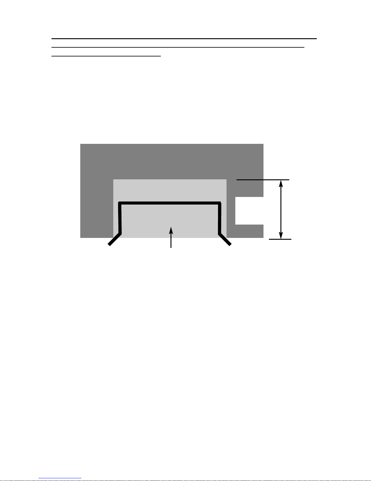
1.6 FIRE PLACE OPENING AND CHIMNEY CATCHMENT SPACE
The front opening of the fire place must be between 330 and 440 mm wide, and
between 550 and 575mm high. If the opening exceeds these dimensions then a
surround must be constructed from suitable non-combustible material to produce a
correct size opening. Any surround must be suitably sealed to the fire place to
prevent leakage. See below in fig.1
When installing into a brick built chimney, you must ensure that there is sufficient
depth to accomodate any debris which may fall from the chimney. This depth
must be sufficient to accomodate 12 litres of volumetric space.
6
Fire Opening
330mm Minimum
440mm Maximum
600mm
Minimum
355mm Minimum
Fig. 1
550mm Minimum
575mm Maximum
Minimum Flat
Sealing Area
Installation Depth Requirements for a Gallery Slimline Open Fronted Radiant
Gas Fire being installed into a brick built chimney, requiring 12.0 litres of
debris collection volume (fig. 2)
There must be a minimum depth of 135mm in the chimney to allow a debris
collection volume of 12 litres to be achieved.
Fig. 2
1.7 FITTING TO PRE-FABRICATED TWIN WALL METAL FLUE BOXES
The appliance may be fitted to twin wall metal flue boxes conforming to the
constructional requirements of BS 715 / BS EN 1856-2. The box must have a
minimum flue diameter of 125mm internal and minimum internal dimensions of
300mm deep by 685mm high by 470mm wide. There are no maximum
dimensional requirements for the box. The top face of the box must be insulated
with a minimum thickness of 50mm of non-combustible mineral wool insulation or
similar material. The flue box must stand on a non-combustible base of minimum
thickness 12mm.
7
Depth Required
(e.g. 135mm
minimum)
Builders Opening

1.8 FITTING TO PRE-CAST FLUE INSTALLATIONS
When installing this appliance into pre-cast flues, always ensure that the
spigot restrictor baffle has been removed. This is held in place on the spigot
by 2 screws. To install the fire box in to pre-cast flue starter blocks, there
must be at least 125mm from the mounting face of the fire to the rear of the
pre-cast flue starter block to allow sufficient space for debris collection. If this
dimension is less than 125mm then a fire surround with a deeper rebate to
increase the depth to at least 125mm from the mounting face of the fire. It is
important to consider this depth when choosing a fire surround as the thickness of
the fire surround must be sufficient to give a total depth of at least 125 mm to the
rear of the starter block, otherwise there will be insufficient depth. To increase
this depth the fire surround may be packed away from the wall using suitable noncombustible board, providing the installation is correctly sealed. If in doubt about
the suitability of the fire contact BFM Europe Ltd. for advice before proceeding.
It is important to ensure that the pre-cast flue is in good condition and is free from
extruded mortar or sealant from between the flue blocks.
This appliance has been tested for use in a pre-cast flue block complying
with BS EN 1858. In accordance with BS EN 1858, pre-cast flues built with
directly plastered faces (front or rear) are not correctly installed as to ensure
proper operation with any type of gas fire. In some instances of this flue
construction, temperature cracking of surface plaster may occur through no
fault of the appliance. An air gap or some form of insulation material should
be installed to prevent normal flue temperatures from damaging wall
surfaces.
1.8 HEARTHS
This appliance must only be installed on to a concrete or non-combustible hearth.
The hearth material must be a minimum thickness of 13mm with the top surface at
least 50mm above the floor. The hearth must be fitted symmetrically about the fire
opening and have a minimum width of 770mm and a minimum projection of
300mm forwards from the fire opening.
1.9 SPILLAGE MONITORING SYSTEM
This appliance is fitted with an atmosphere sensing spillage monitoring system in
the form of an oxygen sensing pilot. This is designed to shut the fire off in the
event of a partial or complete blockage of the flue causing a build up of
combustion products in the room in which the fire is operated. The following are
important warnings relating to this spillage monitoring system :-
1) The spillage monitoring system must not be adjusted by the installer.
2) The spillage monitoring system must not be put out of operation.
3) When the spillage monitoring system is exchanged only a complete original
manufacturers part may be fitted.
8

SECTION 2
INSTALLATION OF FIRE
2.1 UNPACKING THE FIRE
Carefully lift the fire out of the carton. Remove the loose item packaging carefully
from the front of the appliance. Check the contents as listed :-
Packing Check List
1 off Fire box / burner assembly
1 off Boxed ceramic base and 7 synthetic coals
1 off Loose items bag.
1 off Bag of 5 decorative coals
1 off Installation & user book(combined)
1 off Left hand corner blanking plate
1 off Right hand corner blanking plate
2.2 INSTALLING THE FIRE BOX
Establish which type of flue you are intending to install the fire in to :-
225 x 225mm (9 inch x 9 inch) brick built chimneys
175mm (7 inch) diameter lined brick or stone flue, insulated pre-fabricated
metal flue box to BS 715 / BS EN 1856-2
When installing into 125mm (5 inch) diameter lined brick or stone flue, or
insulated pre-fabricated metal flue box to B.S. 715 and pre-cast flues the
restrictor baffle must not be fitted.
A spillage test must always be carried out to check satisfactory
clearance of flue products, regardless of the type of flue the
appliance is being fitted to.
9

For all models proceed as follows :-
a) Ensure that the rear cast is secured firmly to the front casting with 5 off
bolts as shown below in Fig. 3. then apply suitable high temperature
(300 degree celcius rated) sealant to the entire join line between the 2
castings. If either the front or rear casting is damaged (i.e. cracked) do
not proceed with the installation.
Fig. 3
10
Check 5 off bolts
are secure and seal
completely (no visible
gaps) between the
mounting faces of the
two casts

Removal of the canopy :-
b) Remove the canopy by unscrewing the M5 wing nut as shown below in
Fig. 4 then lifting out via the retaining hooks. Store the canopy in a safe
position until it is ready for re-fitting (see section 3.4).
Fig. 4
11
M5 Wing Nut
Retaining Lugs
 Loading...