

Page 1

CAPTUS® 2000
THYROID UPTAKE SYSTEM
OWNER’S MANUAL
Capintec, Inc.
Sales and Marketing
and Customer Support
6 Arrow Road
Ramsey, NJ 07446
Phone (800) ASK-4CRC
Fax (201) 825-1336
Capintec, Inc.
Service Center
540 Alpha Drive
Pittsburgh, PA 15238
Phone (800) 227-6832
Fax (412) 963-0610
©
1993 Capintec, Inc.
Rev. J – February 2001
CAPTUS
Copyright
®
is a registered trademark of Capintec, Inc.
ALL RIGHTS RESERVED
Manual Stock No. 9250-0059-A
Page 2

Page 3

CAPINTEC, INC CAPTUS® 2000
TABLE OF CONTENTS
SAFETY
Symbol Definitions....................................................................................... 1-1
Warning and Caution Labels ....................................................................... 1-2
Cautions and Notes..................................................................................... 1-4
General Safety Tips..................................................................................... 1-5
FUNCTIONAL & TECHNICAL DESCRIPTION
General........................................................................................................ 2-1
Technical Description .................................................................................. 2-1
Detector ........................................................................................... 2-1
Multichannel Analyzer...................................................................... 2-2
Technical Specifications.............................................................................. 2-3
Thyroid Uptake Stand ...................................................................... 2-3
System Power Requirements .......................................................... 2-3
Environment requirements............................................................... 2-3
Operational .......................................................................... 2-3
Storage ................................................................................ 2-4
Isolation Transformer....................................................................... 2-4
Printer .............................................................................................. 2-4
Computer System (Minimum System Requirements)...................... 2-4
MCA Interface PC Board (Accuspec/NaI Plus
Amplifier Switch PC Board................................................... 2-5
CAPTUS
TUS Probe Detector ........................................................................ 2-5
Well Detector – Optional.................................................................. 2-5
Regulatory Listings .......................................................................... 2-6
EMC ..................................................................................... 2-6
Electrical .............................................................................. 2-6
ETL Listed............................................................................ 2-6
Functional Description................................................................................. 2-6
Thyroid Uptake ................................................................................ 2-6
Wipe Test......................................................................................... 2-7
Lab Tests – Urine................................................................. 2-7
Lab Tests – Blood ................................................................ 2-8
Bioassay .......................................................................................... 2-9
®
2000 Software Package...................................... 2-5
®
Board......... 2-5
February 01 TABLE OF CONTENTS TOC-1
Page 4

CAPINTEC, INC CAPTUS® 2000
GENERAL OPERATING INSTRUCTIONS
Windows Operating Conventions................................................................ 3-1
Common Controls and Technique .............................................................. 3-1
Windows Controls ....................................................................................... 3-1
Trackball Cursor .............................................................................. 3-1
Command Button............................................................................. 3-2
Frame .............................................................................................. 3-3
Radio Button........................................................................ 3-3
Check Box ........................................................................... 3-3
Text Entry Box................................................................................. 3-3
Scroll Bars ....................................................................................... 3-4
Spin Control..................................................................................... 3-5
List Controls .................................................................................... 3-5
Menu Bars ....................................................................................... 3-5
Keyboard Control ............................................................................ 3-5
Switching to Other Windows Applications ....................................... 3-6
SYSTEM SETUP
Installation ................................................................................................... 4-1
Environment Requirements......................................................................... 4-1
Operational...................................................................................... 4-1
Storage............................................................................................ 4-1
Power Requirements................................................................................... 4-1
Turn On Procedure ..................................................................................... 4-2
General Operational Setup ......................................................................... 4-3
System Parameters..................................................................................... 4-4
Normal Values............................................................................................. 4-7
Reference Standards .................................................................................. 4-8
Isotope Library ............................................................................................ 4-10
Entering Isotope Information ....................................................................... 4-10
Efficiency Measurements ............................................................................ 4-11
Archive Files................................................................................................ 4-17
QUALITY ASSURANCE
Warm Up ..................................................................................................... 5-1
Daily Tests and Calibration ......................................................................... 5-1
Energy Calibration........................................................................... 5-2
Constancy ....................................................................................... 5-5
Quarterly Tests............................................................................................ 5-7
Chi-squared Test............................................................................. 5-7
Detector Resolution......................................................................... 5-8
Interpreting Test Results ............................................................................. 5-8
Printing Test Results ................................................................................... 5-10
TOC-2 TABLE OF CONTENTS February 01
Page 5

CAPINTEC, INC CAPTUS® 2000
THYROID UPTAKE
General Information..................................................................................... 6-1
Defining a Measurement Protocol ............................................................... 6-2
Adding Protocols.............................................................................. 6-3
Protocol Name ................................................................................. 6-4
Counting Method ............................................................................. 6-5
Multiple Capsule Administration ...................................................... 6-6
Counting Repetitions, Dose Form, and Predose Measurements .... 6-6
Isotope ............................................................................................. 6-7
Viewing, Editing, Deleting and Restoring Patients ...................................... 6-8
Regions of Interest ...................................................................................... 6-9
Counting Time and Probe Distance............................................................. 6-11
Adding New Patients ................................................................................... 6-11
Editing Patient Information .......................................................................... 6-13
Administer Dose .......................................................................................... 6-14
Deleting Information .................................................................................... 6-15
Making Measurements ................................................................................ 6-16
Predose Measurements................................................................... 6-18
Capsule Count Measurement .......................................................... 6-20
Room Background Measurement .................................................... 6-22
Patient Background Count............................................................... 6-23
Patient Neck Count.......................................................................... 6-24
Results......................................................................................................... 6-25
Printing Results ........................................................................................... 6-25
WIPE TESTS
Adding Wipe Locations................................................................................ 7-2
Isotope Efficiency ........................................................................................ 7-3
Edit Information ........................................................................................... 7-4
Deleting Wipe Test Information ................................................................... 7-4
Making Measurements ................................................................................ 7-5
Results......................................................................................................... 7-7
Counting the Next Wipe............................................................................... 7-9
Printing Results ........................................................................................... 7-10
Background Measurement............................................................... 7-6
Wipe Measurement.......................................................................... 7-7
Adding Text Comments ................................................................... 7-8
Detailed Analysis Report ................................................................. 7-10
Summary History Report ................................................................. 7-10
Text Comments for the Summary Wipe History Report................... 7-12
Deleting Wipe Test History .............................................................. 7-14
February 01 TABLE OF CONTENTS TOC-3
Page 6

CAPINTEC, INC CAPTUS® 2000
LAB TESTS
Schilling Test............................................................................................... 8-2
Setup Counting Parameters ............................................................ 8-3
Adding Patients ............................................................................... 8-4
Editing Patient Information .............................................................. 8-6
Deleting Patient Information ............................................................ 8-6
Making Measurements .................................................................... 8-8
Test Results .................................................................................... 8-11
Printing Results ............................................................................... 8-12
Dicopac
Blood Volume Test...................................................................................... 8-26
RBC Survival Test....................................................................................... 8-38
®
Test.............................................................................................. 8-14
Adding Patients ............................................................................... 8-15
Editing Patient Information .............................................................. 8-16
Deleting Patient Information ............................................................ 8-17
Making Measurements .................................................................... 8-18
Test Results .................................................................................... 8-23
Printing Test Results ....................................................................... 8-23
Adding Patients ............................................................................... 8-26
Editing Patients ............................................................................... 8-29
Deleting Patient Information ............................................................ 8-29
Making Measurements .................................................................... 8-30
Test Results .................................................................................... 8-35
Printing Test Results ....................................................................... 8-36
Adding Patients ............................................................................... 8-39
Editing Patient Information .............................................................. 8-41
Deleting Patient Information ............................................................ 8-41
Making Measurements .................................................................... 8-43
Test Results .................................................................................... 8-47
Printing Test Results ....................................................................... 8-47
BIOASSAY
Bioassay Setup ........................................................................................... 9-2
Efficiency Measurements ............................................................................ 9-3
Printing Efficiency Results........................................................................... 9-6
Adding Staff................................................................................................. 9-8
Editing Staff Information.............................................................................. 9-9
Deleting Staff Information............................................................................ 9-9
Making Measurements................................................................................ 9-10
Results ........................................................................................................ 9-13
Printing Results ........................................................................................... 9-13
MCA
Setup Menu................................................................................................. 10-2
Setting Presets ................................................................................ 10-2
High Voltage/Amplifier Adjustment.................................................. 10-3
ADC/Zero Adjustments.................................................................... 10-4
Quick Calibration Restore ............................................................... 10-5
TOC-4 TABLE OF CONTENTS February 01
Page 7

CAPINTEC, INC CAPTUS® 2000
MCA (cont)
Acquisition and Count Data......................................................................... 10-6
Regions of Interest (ROI)............................................................................. 10-7
Save and Restore Count Data or MCA Settings ......................................... 10-8
Save MCA Settings.......................................................................... 10-8
Recall MCA Settings........................................................................ 10-9
Save Spectrum ................................................................................ 10-10
Recall Spectrum .............................................................................. 10-10
Manipulation of Acquired Spectrum............................................................. 10-11
Moving the Displayed Spectrum A and B ........................................ 10-11
Applying Spectral Filters .................................................................. 10-12
Quadratic Smooth ................................................................ 10-14
st
1
Derivative ........................................................................ 10-14
nd
2
Derivative ....................................................................... 10-14
Printing MCA Data....................................................................................... 10-15
Time Activity Analysis.................................................................................. 10-17
Setup Information ............................................................................ 10-17
Making Measurements .................................................................... 10-19
Displaying Results ........................................................................... 10-20
Save Time Activity Results .............................................................. 10-22
Recall Time Activity Results ............................................................ 10-22
Printing Results ........................................................................................... 10-23
CLEANING AND MAINTENANCE
Introduction.................................................................................................. 11-1
Cleaning Instructions................................................................................... 11-1
Floor Stand ...................................................................................... 11-1
Detectors ......................................................................................... 11-1
Pointer Assembly............................................................................. 11-1
Keyboard ......................................................................................... 11-2
Monitor Screen ................................................................................ 11-2
Computer And Monitor Cases ......................................................... 11-2
Printer .............................................................................................. 11-2
Printer Cartridges............................................................................. 11-2
Trackball .......................................................................................... 11-2
Preventive Maintenance .............................................................................. 11-3
Servicing...................................................................................................... 11-3
Disposal....................................................................................................... 11-3
Fuse Servicing............................................................................................. 11-4
Power Line Fuses ............................................................................ 11-4
Computer, Monitor and Printer Fuses.............................................. 11-5
Accessories And Replacement Parts .......................................................... 11-5
Shipping....................................................................................................... 11-5
WARRANTY
DECLARATION OF CONFORMITY
February 01 TABLE OF CONTENTS TOC-5
Page 8

Page 9

CAPINTEC, INC CAPTUS® 2000
PREFACE
Thank you for purchasing the CAPINTEC line of Thyroid Uptake Measurement Systems.
Every effort has been made to insure that the information in this document is complete,
accurate, and up-to-date. CAPINTEC assumes no responsibility for the results of errors
beyond its control. Mention of products manufactured by other companies does not
necessarily constitute endorsement by CAPINTEC, Inc.
CAPTUS
Microsoft
the Microsoft Corporation.
Hewlett Packard
DICOPAC
Arlington Heights, IL.
®
2000 and CII are registered trademarks of CAPINTEC, Inc.
®
, Windows®, MS Windows®, and Windows® 95 are U.S.registered trademarks of
®
DeskJet is a registered trademark of the Hewlett Packard Company.
®
is a registered trademark of Medi-Physics, Inc., an Amersham Company of
SYSTEM DESCRIPTION
Your new CAPTUS® 2000 is available in several configurations. Please take a moment to
review your system to determine exactly the configuration you have received. The basic
thyroid uptake system consists of the following:
• Floor stand with TUS Collimator and isolation transformer
• NaI (sodium iodide) Detector with Detector Socket Base
Note: Two versions of detectors are available: Flat Face Probe or Drilled Probe.
• Computer System with MCA Board and amplifier/switch PC Board Installed
• Computer Monitor
• Printer (Various options are available here)
• Cable Set for Connecting detector, printer, etc.
• 15 foot power cord with hospital grade plug
• Software and Documentation
• Windows 95 or later, Manuals and Distribution Disks
• CAPTUS
• Well Counter with drilled well detector (Optional purchase)
®
2000 Manual and Installation Disks or CDs
July 00 PREFACE P-1
Page 10

CAPINTEC, INC CAPTUS® 2000
YEAR 2000 COMPLIANCE
The CAPTUS® 2000 measurement systems contain information technology that accurately
processes date and time data between the years 1999 and 2000. These products, when
used in combination with products purchased from other manufacturers, whose products
properly exchange date and time information, will accurately process the date and time. All
future products are committed to meeting the same Year 2000 Compliance.
MEDICAL EQUIPMENT SAFETY CLASSIFICATION
• CLASS I EQUIPMENT energized from an external power source.
• TYPE B EQUIPMENT with no applied parts to the patient.
• Ordinary EQUIPMENT without protection against the ingress of water.
• Suitable for CONTINUOUS OPERATION.
• NOT suitable for use in an OXYGEN or a FLAMMABLE ENVIRONMENT.
ELECTROMAGNETIC INTERFERENCE POTENTIAL
This equipment complies fully with interference immunity requirements of the standard EN
60601-1-2 “Medical electrical equipment: Part 1: General safety requirements; 2.
Supplementary standard: Electromagnetic compatibility”.
This equipment generates radio frequency energy and, if not installed and used in
accordance with the instructions, may cause harmful interference to nearby devices.
However, there is no guarantee that interference will not occur in a particular installation. If
this equipment does cause harmful interference, the user is encouraged to try to correct the
interference by one of the following measures:
• Increase the separation between the equipment and the affected device.
• Plug the unit into an outlet on a circuit different from that which the affected device is
connected.
If this fails to correct the problem, please contact Capintec.
IMPORTANT SAFETY INFORMATION
The CAPTUS® 2000 measurement system has been carefully designed to give you years of
safe and reliable performance. As with all electrical equipment, however, there are basic
precautions you must observe to avoid injuring yourself, the patient or damaging the
equipment.
• Follow
carefully before using this equipment. Be sure to save all provided documents for
future reference.
• Understand
before operating this equipment.
the unpacking and assembly instructions document, and read this manual
all warning and caution labels as explained in the “SAFETY” chapter
P-2 PREFACE July 00
Page 11
CAPINTEC, INC CAPTUS® 2000
CHAPTER 1
SAFETY
These warnings and instructions for use form an integral part of the CAPTUS
must therefore be kept available for consultation at all times. Precise compliance with the
warnings and instructions is an essential condition for normal use, correct application and
thus safety of patients and user.
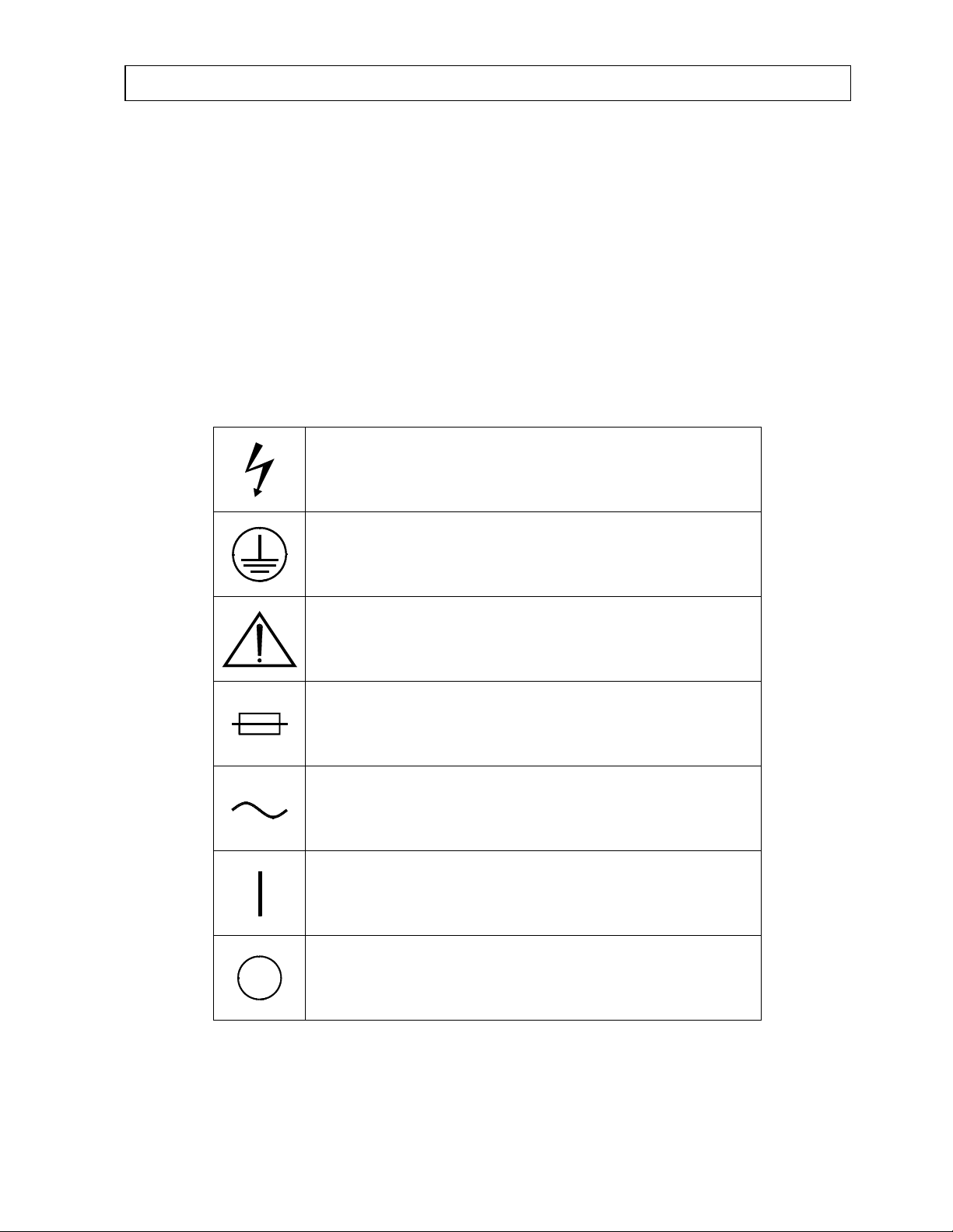
SYMBOL DEFINITIONS
Dangerous Voltage Present
®
2000 and
Protective Earth Ground
Attention: consult owner’s manual for further information
Fuse
AC Voltage
“ON” (power)
“OFF” (power)
July 00 SAFETY 1-1
Page 12
CAPINTEC, INC CAPTUS® 2000
WARNING AND CAUTION LABELS
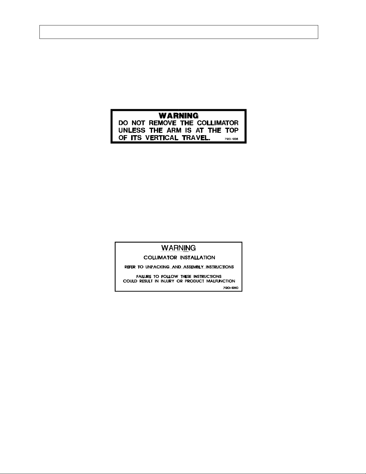
Located in the center section on both sides of the spring-arm of the floor stand is a warning
label, (see Fig. 1-1), concerning the hazard of removing the collimator when the spring-arm is
in the wrong position. When the weight of the collimator is removed from the spring-arm, the
arm can forcefully spring upward and cause serious bodily injury to the operator. The springarm must be fully extended in the upright position to prevent this hazardous condition.
Figure 1-1
Located in the front section on both sides of the spring-arm of the floor stand is a warning
label, (see Fig. 1-2), concerning the hazard of improperly installing the collimator onto the
spring-arm. If the collimator support pin is not fully inserted and latched into the receptacle
block of spring arm, the collimator may detach from the spring-arm and fall onto the patient.
In addition, the arm can, again, forcefully swing upward and cause serious bodily injury to the
operator. The collimator is safely installed on the spring-arm when the red warning ring is
NOT visible between the collimator and the receptacle block. Refer to the UNPACKING AND
ASSEMBLY INSTRUCTIONS for illustrations.
Figure 1-2
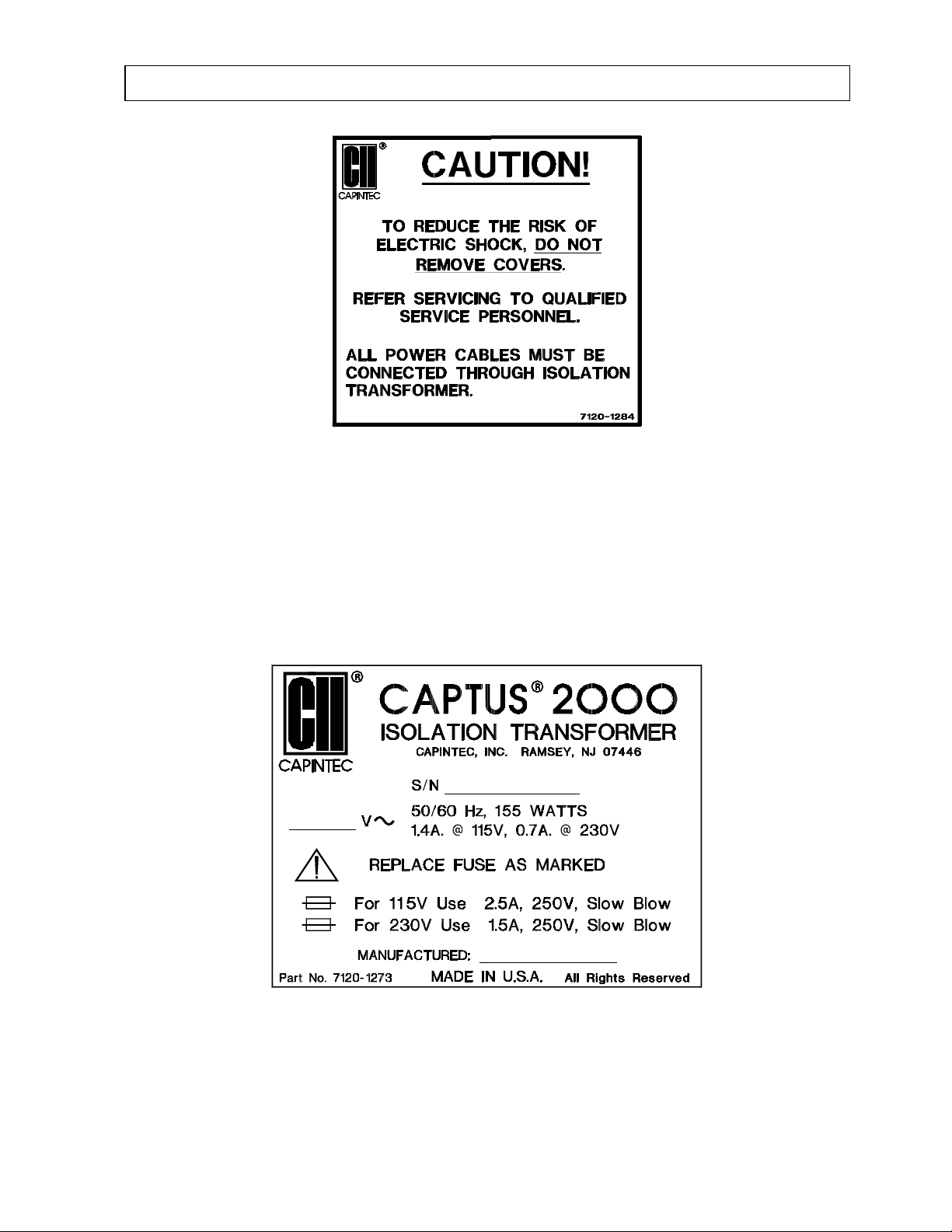
Located on the top right hand side of the computer case is a label, (see Figure 1-3),
containing three caution statements pertaining to electrical safety of the computer. The first
statement, DO NOT REMOVE COVERS, is necessary because of the high voltage present
(1000 volts) on the PC boards installed in the computer. A screwdriver is necessary to
remove the covers. The second statement, REFER SERVICING TO QUALIFIED SERVICE
PERSONNEL, informs the user that no servicing in the computer system may be performed
by the user. The third statement, ALL POWER CABLES MUST BE CONNECTED
THROUGH THE ISOLATION TRANSFORMER, is necessary to eliminate any shock hazard
to the patient (and the user). The isolation transformer insures the leakage current of the
computer system is less the 50 µAmps as stipulated by the UL 544 safety standard.
1-2 SAFETY July 00
Page 13
CAPINTEC, INC CAPTUS® 2000
Figure 1-3
Located on the top of the Isolation Transformer is a label, (see Figure 1-4), providing the
system power requirements, the voltage and serial number of the system and the
replacement fuse values for both power line voltages.
Please refer to CHAPTER 11: CLEANING AND MAINTENANCE for instructions on how to
change the fuse on the CAPTUS
A fire hazard may exist if the wrong size of fuse is installed.
®
2000 Isolation Transformer.
Figure 1-4
July 00 SAFETY 1-3
Page 14
CAPINTEC, INC CAPTUS® 2000
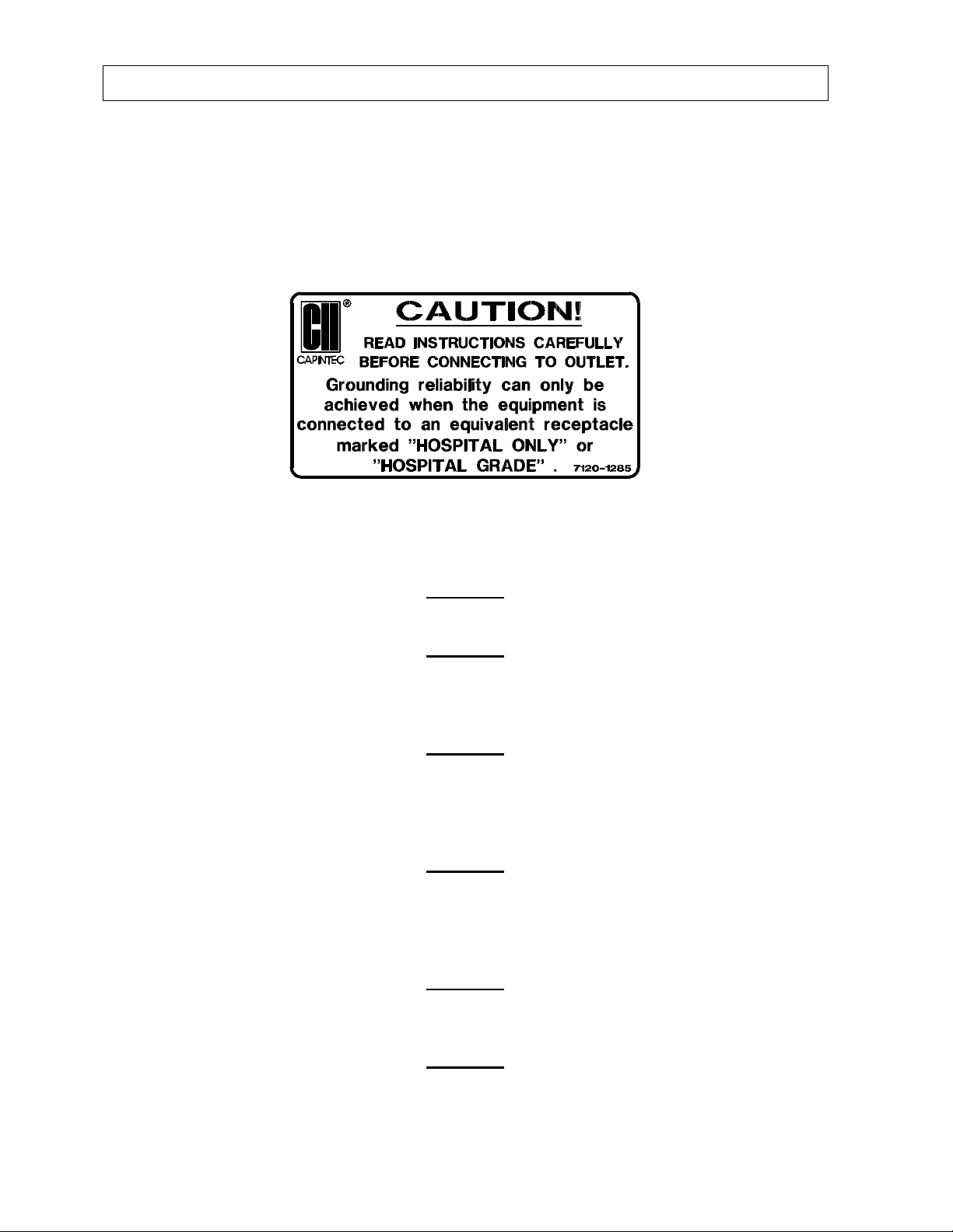
Located on the left side of the Isolation Transformer is a label, (see Fig. 1-5), with two
caution statements pertaining to the main power cord of the Isolation Transformer. The
statement, READ INSTRUCTIONS CAREFULLY BEFORE CONNECTING TO OUTLET,
directs the user to the owners manual before connecting the power. The second statement
alerts the user to select an electrical power receptacle that is designated as HOSPITAL
ONLY or HOSPITAL GRADE, to insure reliable grounding is provided to the CAPTUS
system for electrical safety requirements.
Figure 1-5
®
CAUTIONS AND NOTES
CAUTION
Only qualified/trained personnel should operate or service this unit.
CAUTION
High voltage is present inside the Detectors (up to 1000 Volts). Due to the presence of these
high voltages, opening the covers with the system plugged in may be hazardous. Refer all
servicing to qualified personnel.
CAUTION
No internal adjustments inside the Detector, Computer or Printer that may be performed by
the user within the conditions of the warranty, except for changing the Isolation Transformer
fuse. Due to the presence of high voltages, opening the cover of the Computer with the
system plugged in may be hazardous. Refer all servicing to qualified personnel.
CAUTION
Never use the Well Detector without the well liner in place. Liners are inexpensive and easy
to replace. A contaminated Detector is a very costly mistake. If unit becomes contaminated
remove liner and clean unit as stated in CHAPTER 11: CLEANING AND MAINTENANCE
before operating.
CAUTION
Care must be exercised when moving the system or when maintenance is performed. The
system must not be inclined more than a 15 degree angle or tip over may occur.
CAUTION
Verify that the Collimator is correctly installed as stated in the Unpacking and Assembly
Instructions. Failure to follow these instructions could result in injury or product malfunction.
1-4 SAFETY July 00
Page 15

CAPINTEC, INC CAPTUS® 2000
CAUTION
This equipment generates radio frequency energy and, if not installed and used in
accordance with the instructions, may cause harmful Electromagnetic Interference (EMI) to
nearby devices. However, there is no guarantee that interference will not occur in a
particular installation.
CAUTION
If any printer other than the model supplied by Capintec is used, the safety of the unit may be
compromised or Electromagnetic Interference (EMI) may be introduced into other devices
located in the same general area as the CAPTUS
CAUTION
The unit contains lead. The unit should be disposed of in accordance with local and national
regulations.
CAUTION
The unit contains a Lithium Battery. This should be disposed of in accordance with local and
national regulations.
CAUTION
The user should always verify the validity of any measurement or test result in order to
minimize measurement errors.
NOTE
It is recommended that periodic (every five years) re-calibration of the unit be performed by
Capintec to guarantee that the instrument's high reliability is maintained).
®
2000 may become susceptible to EMI.
GENERAL SAFETY TIPS
• Unplug the equipment before cleaning it. Use only a damp cloth; do not use liquids or
aerosol cleaners.
• To protect the equipment from overheating, make sure none of the openings (vents)
on the Computer, Monitor, or the Printer are blocked.
• Do not use the equipment near water, or spill liquids of any kind into the equipment.
• Be sure that your power source matches the rating listed on the Isolation
Transformer.
• The CAPTUS
and it will only fit into a grounded outlet. Do not use an adapter to defeat the
grounding.
• The CAPTUS
comply with electrical safety for Medical Electrical Equipment. Due to the risk of
electrical shock, do not install or use a Modem or a Network adapter with the
CAPTUS
July 00 SAFETY 1-5
®
2000 power cord has a grounded, 3-prong plug as a safety feature,
®
2000 computer system is connected to the Isolation Transformer to
®
2000 computer system.
Page 16

CAPINTEC, INC CAPTUS® 2000
• To avoid damaging the power cord, do not place anything on it or place it where it will
be walked on. If the cord becomes damaged, replace it immediately.
• Aside from the routine maintenance described in this manual, do not try to service
this equipment yourself. There are no user serviceable parts contained in the system
other than the fuses in the Isolation Transformer. Do not make any adjustments other
than those outlined in this manual, as you may in-validate the calibration or cause
damage requiring extensive repair work. Refer servicing to qualified service
personnel.
• Do not subject the Detectors to rough handling, or rapid temperature changes, as the
NaI Scintillation Crystal can be damaged. Do not use the equipment directly in front
of a radiator, heat register, or air conditioning duct.
1-6 SAFETY July 00
Page 17

CAPINTEC, INC CAPTUS® 2000
CHAPTER 2
FUNCTIONAL & TECHNICAL
DESCRIPTION
GENERAL
The CAPTUS® 2000 Thyroid Uptake / Well Systems is intended to be used by trained
Nuclear Medicine Technologists for performing Thyroid Uptake, Thyroid Bioassay, Wipe
Test, Blood Volume (with Cr-51 or I-125) Test, Shillings (including DICOPAC
Survival Test.
The CAPTUS
decay corrections, efficiency calculations, and maintains appropriate storage and retrieval
files for reference data, and patient demographic data.
®
2000 also performs Pulse Height Analysis, isotope identification, radioisotope
®
) Test and RBC
TECHNICAL DESCRIPTION
The CAPTUS® 2000 is based on a powerful personal computer, with a windows-based
operating system.
The basic Thyroid Uptake system consists of the following:
• Floor stand with TUS Collimator and isolation transformer
• NaI (sodium iodide) Detector with Detector Socket Base
Note: Two versions of detectors are available: Flat Face Probe or Drilled Probe
• Computer System with MCA Board and amplifier / switch PC Board Installed
• Computer Monitor
• Printer
• Cable Set for Connecting detector, printer, etc.
• 15 foot power cord with hospital grade plug
Detector
Your CAPTUS
iodide) crystal and photomultiplier tube detector assemblies, a 1024 channel MCA
(multichannel analyzer), along with associated electronics and electronic controls which
provide power and amplification of the pulses generated by the detectors, as well as software
modules which record, analyze, manipulate, and store the measured data.
Since NaI crystals are hygroscopic, the detector assembly is hermetically sealed with an
aluminum coating. If the seal is broken, then water will be absorbed by the crystal, causing
deterioration of its measurement capabilities, and eventually it will require replacement. For
®
2000 system is equipped with one or two NaI (Tl) (thallium-activated sodium
July 00 FUNCTIONAL & TECHNICAL DESCRIPTION 2-1
Page 18

CAPINTEC, INC CAPTUS® 2000
this reason, always handle the detector with care. Avoid scratching the surface with metal
objects such as pens.
When a gamma or x-ray from a radioactive source reaches the NaI crystal, it collides with the
electrons in the crystal matrix and transfers energy, primarily through Compton interaction.
The excited electron releases this energy as visible light in direct proportion to its absorbed
energy. For this reason, NaI detectors are classified as scintillation detectors. The higher
the energy of the incident ray, the more Compton collisions and consequently the more
visible light emissions will be measured before all of the energy is absorbed. These
sequential emissions of light for each incident ray generated from the sequential Compton
collisions appear to the measuring system as a single light pulse. The intensity of the pulse
is directly proportional to the energy of the incident gamma or x-ray. The light is eventually
directed toward the photomultiplier tube, either by the direction in which it was emitted or by
reflection from the interior of the aluminum housing. The photomultiplier tube, which is
optically connected to the sodium iodide crystal, converts the visible light pulses into
electrical energy and amplifies the signal through a series of dynodes. The resultant
electrical signal is directly proportional to the intensity of the incident light pulse. Therefore,
the pulse height generated by the system is directly proportional to the energy of the incident
gamma or x-ray detected by the system.
Multichannel Analyzer
A multichannel analyzer records the number and height of the electrical pulses generated by
the system, divides the pulses into groups based upon pulse height, and provides a visible
picture or spectrum of the pulses as well as count information. The CAPTUS
®
2000 divides
the pulses into 1024 groups or channels. Since pulse height is directly related to the energy
of the incident photon, the spectrum displays the pulse heights as a graph of pulses or
counts on the vertical scale and energy on the horizontal scale. By matching the displayed
spectrum to the decay scheme of an isotope, positive identification of the radioactive source
can be achieved.
Electronics associated with the process include the high voltage power supply, amplifiers,
and gain adjustments. The high voltage power supply provides voltage to the photomultiplier
tube for the light to electrical impulse conversion and amplification process. The amplifiers
linearly amplify the electrical signal produced by the photomultiplier tube before the signal is
passed to the MCA. The pulse height remains proportional to the energy of the incident ray.
The gain controls the amount of amplification which is performed by the amplifiers, and is
adjustable by the user.
The spectral display also has adjustments which control the pulse height which include zero
adjust, lower level (LLD) and upper level (ULD) discriminators. The zero adjust controls the
channel used for 0 pulse height or 0 energy, The LLD sets the limit for the lowest pulse
height to be analyzed, and the ULD sets the limit for the highest pulse height analyzed.
2-2 FUNCTIONAL & TECHNICAL DESCRIPTION July 00
Page 19

CAPINTEC, INC CAPTUS® 2000
TECHNICAL SPECIFICATIONS
Pentium class computer system including the MS Windows® operating system with a
multichannel analyzer PC Board, two scintillation detectors, a dual input detector
preamplifier/switch PC Board, a trackball pointing device, a color printer, and exceptionally
easy to use CAPTUS
Thyroid Uptake Stand
®
2000 application software.
Rugged floor stand with heavy duty locking casters and an articulating arm for the positioning
of detector/collimator. Individual shelves provided for the CAPTUS
®
2000 computer / monitor
system / monitor and for the printer. Mounting for the isolation transformer and the optional
well detector is provided on the base of the floor stand.
Dimensions: Height 175.3 cm (69")
Width 71.1 cm (28")
Depth 78.7 cm (31")
Weight 181.8 kg (400 lb.)
(with optional well) 213.6 kg (470 lb.)
System Power Requirements
CAUTION
If the input voltage to the following items is not within the stated limits, the unit may not
function correctly or may be damaged.
Standard 115V* 105-127V 1.3 Amps 50/60Hz
Optional 100V* 90-110V 1.5 Amps 50/60Hz.
Optional 230V* 210-255V 0.8 Amps 50/60Hz.
Optional 200V* 180-220V 1.0 Amps 50/60Hz.
*(Transformer Voltage Taps are set at the factory.)
Environment Requirements
Operational
The instrument should be located where the level of the background radiation is as
low and as constant as possible.
The instrument should be located where the temperature is stable within a range of
+50°F to +85°F (+10°C to +30°C) and the maximum relative humidity is 90% noncondensing to warrant maximum reliability and accuracy.
The instrument should be located where the barometric pressure is within a range of
27 – 31 inches of mercury (91 – 105 kilopascals).
July 00 FUNCTIONAL & TECHNICAL DESCRIPTION 2-3
Page 20

CAPINTEC, INC CAPTUS® 2000
Storage
The instrument should be stored where the temperature is stable and the range is
from +39°F to +115°F (+4°C to +43°C) and the maximum relative humidity is 90%
non-condensing to warrant maximum reliability.
The instrument should be stored where the barometric pressure is within a range of
15 – 33 inches of mercury (51 – 112 kilopascals).
CAUTION
If these environmental requirements are not followed, the instrument may display erroneous
readings.
Isolation Transformer
An isolation transformer is provided with the CAPTUS
®
2000 system to insure the leakage
current is less than 50 µA as specified in the UL544 Medical Equipment Safety Standard. A
detachable 4.6m (15 ft) power cord, with a hospital grade plug, is provided to connect the
isolation transformer to the power source. Dual power line fuses are provided at the power
entry module for quick replacement.
Dimensions: Height 15.2 cm (6")
Width 12.7 cm (5")
Depth 10.2 cm (4")
Printer
Hewlett Packard
including graphic displays
Dimensions: Height 20.8 cm (8.2”)
Computer System (Minimum System Requirements)
®
DeskJet – thermal inkjet color printer, prints results of studies
Width 44.4 cm (17.5”)
Depth 38.9 cm (15.3”)
Weight 6.6 kg (14.5 lbs)
IBM compatible, 486 SX/33 CPU
Desktop Case
3½”, 1.44MB Diskette Drive
170MB Hard Drive
8MB RAM
SVGA Graphics Card (800×600, 256 Colors)
SVGA 14” Color Monitor with Swivel Base
Enhanced Keyboard and Trackball
MS Windows
®
operating system Version 3.1
2-4 FUNCTIONAL & TECHNICAL DESCRIPTION July 00
Page 21

CAPINTEC, INC CAPTUS® 2000
MCA Interface PC Board (Accuspec/NaI Plus® Board)
1024 Channels
3 conversion gains: 256, 512, 1024
Maximum Count Rate 100,000 cps
ROI's – Automatic or Manual
QA automatic-gain adjust, energy calibration, resolution, chi-squared, constancy
Automatic efficiency calculation and storage
Adjustable Lower Level Discriminator
Differential Nonlinearity <2% over the top 98% of channels
Integral Nonlinearity <1% over the top 98% of channels
Adjustable Zero
Adjustable Upper Level Discriminator
Preset Live Time, Real Time, Total Counts
Automatic Peak Finding
Full length, 8 bit ISA Bus computer interface
Amplifier/Switch PC Board
Permits software control of detector selection
SHV connectors for TUS Probe and Well Detectors
Half length, 8 bit ISA Bus computer interface
CAPTUS
TUS Probe Detector
®
2000 Software Package
Stores and prints all test data results
Reference library for isotopes
User definable normal ranges on printout
Thyroid Uptake
Wipe Test
Schilling Test
Dicopac Test
Blood Volume
RBC Survival
MCA
NaI(TI) flat face crystal / PM Tube: 5.1 x 5.1 cm (2" x 2")
Features Monoline construction
Pulse Height Resolution - 8% or better for Cs137
Lead Shielded Collimator
Complies with ANSI Standard N44.3-1973
Lined with brass to minimize back scatter
Well Detector – Optional
With attached 10 ft. coaxial signal / high voltage cable. Allows for the placement of
the well off of the floor stand.
July 00 FUNCTIONAL & TECHNICAL DESCRIPTION 2-5
Page 22

CAPINTEC, INC CAPTUS® 2000
NaI(TI) well type crystal / PM Tube: 5.1 x 5.1 cm (2" x 2")
Well diameter: 1.6 cm (0.625")
Well depth: 4 cm (1.5")
Featuring Monoline construction
Pulse Height Resolution – 8.5% or better for Cs137
Lead shielding – lined with brass (0.16 cm (1/16”) thick) to minimize back scatter
Thickness: 2.5 cm (1")
Height: 32.5 cm (12.8")
Diameter: 11.4 cm (4.5")
Weight: 27.9 kg (61.4 lb.)
Regulatory Listings
The CAPTUS
the following Standards:
EMC
Electrical
®
2000 has been independently tested and is manufactured in compliance with
• European Union Norm EN 60601-1-2: Medical Electrical Equipment – Part 1
General Requirements for Safety – Section 1.2 Collateral Standard:
Electromagnetic Compatibility – Requirements and Tests
• European Union Norm EN 60601-1: Medical Electrical Equipment – Part 1
General Requirements for Safety
• European Union Norm EN 60601-1-1: Medical Electrical Equipment – Part 1
General Requirements for Safety – Section 1.1 Collateral Standard: Safety
Requirements for Medical Electrical Systems
ETL Listed
FUNCTIONAL DESCRIPTION
Thyroid Uptake
Thyroid uptake is a measurement of the ratio of the amount of radioactive material
concentrated in the thyroid gland to the amount of radioactive material administered to the
patient. Thyroid uptake measurements are generally used to determine conditions of
hyperthyroidism. High uptake results are found in Graves disease, toxic nodular goiter, TSHinduced, or with stimulator secreting tumors. Low uptake results are found with thyroid
hormone secretion in ectopic tumors, hormonal release in thyroid injury, after intake of
thyroid hormone, or Jod-Basedow disease. During the treatment of thyroid cancer by I-131
oblation, uptake measurements are used to monitor thyroid activity.
The CAPTUS
data for both the administered dosage and the patient, decay correct all count data, calculate
thyroid uptake results, and store all of this information in the thyroid uptake library. Regions
®
2000 system will store patient demographic and dosage information, count
2-6 FUNCTIONAL & TECHNICAL DESCRIPTION July 00
Page 23

CAPINTEC, INC CAPTUS® 2000
of Interest have been defined for three isotopes, I-131, I-123, or Tc-99m. If normal values
have been entered, then results exceeding these values will be flagged. All of the patient
information may be printed. The thyroid uptake software has been designed to
accommodate a variety of different counting protocols, using either capsules or liquid
dosages.
Wipe Test
The Wipe Test measures radioactive contamination for nuclear medicine departments and
laboratories, as mandated by state and federal radiation safety requirements.
Lab Tests – Urine
Schilling Test
The Schilling Test utilizes Cobalt 57 labeled Vitamin 12 and is used to determine B12 deficiencies from either malabsorption, lack of intrinsic factor (pernicious anemia),
or intraintestinal destruction. The test entails collection of urine for 24 or 48 hours
after the oral administration of radioactive labeled vitamin B-12. The ratio of excreted
to administered Co57 is calculated. If the initial results indicate a reduced amount of
excreted vitamin, the test is repeated with a second sample of labeled B-12 and
intrinsic factor. For Schilling Test I, abnormal results are generally less than 8%-10%.
Normal range is generally 11% to 26%. For Schilling Test II, no change indicates
malabsorption, while an improved percentage indicates pernicious anemia.
DICOPAC
The DICOPAC® Test utilizes Cyanocobalamin Cobalt 57 (Co57 labeled Vitamin B-12)
bound to Human Gastric Juice (Intrinsic Factor), and Cyanocobalamin Cobalt 58
(Co58 labeled Vitamin B-12). The test is used to determine B-12 deficiencies from
either malabsorption, lack of intrinsic factor (pernicious anemia), or intraintestinal
destruction. With the administration of both isotopes simultaneously, the DICOPAC
Test accomplishes the equivalent of both the Schilling Test I and Schilling Test II at
the same time. The test entails collection of urine for 24 hours after the oral
administration of radioactive labeled vitamin B-12 capsules.
The ratio of excreted to administered Co57 and Co58, and the Co57/Co58 ratio is
calculated. Malabsorption syndromes not caused by lack of intrinsic factor yield
below normal results for both Co57 and Co58 excretion, and a 57/58 ratio of about 1.
Patients with pernicious anemia have decreased Co58 excretion, low normal to
normal Co57 excretion, and an increased 57/58 ratio which generally exceeds 1.4.
The algorithm used in the DICOPAC
background. The background can be caused by other sources (or other peaks from
the same source). Therefore, this algorithm eliminates spillover. The algorithm
begins after the centroid of the peak is found. The endpoints of the peak are the
hwtm (half width-tenth maximum) on either side of the centroid. The background is
found from the 5 points on either side of the peak.
®
Test
®
calculation finds the net counts above any
®
July 00 FUNCTIONAL & TECHNICAL DESCRIPTION 2-7
Page 24
CAPINTEC, INC CAPTUS® 2000
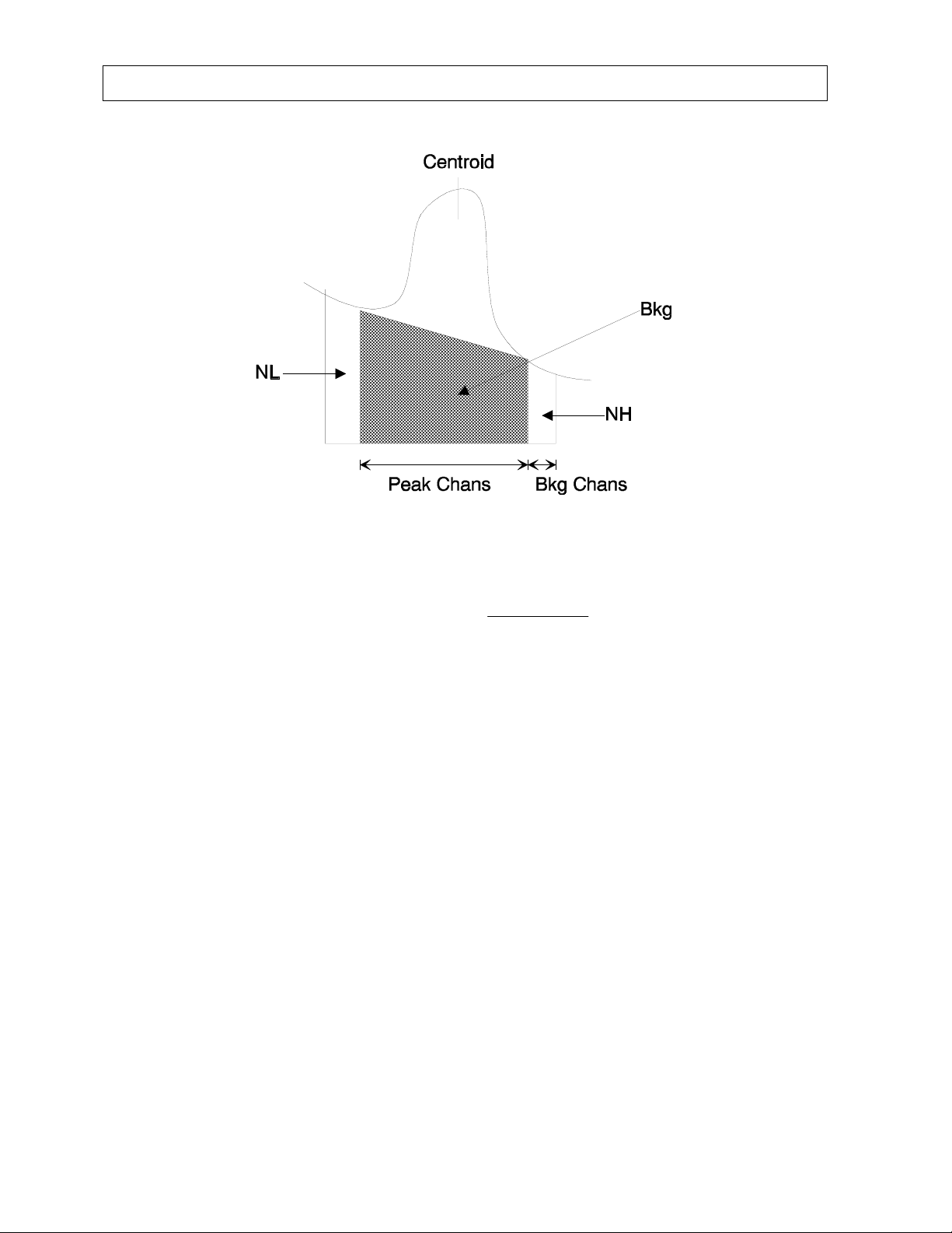
The background is the filled area under the peak marked Bkg. The area is given by:
NHNL
where
When the background is calculated it is subtracted from the total counts within the
peak channels to find the net counts within the peak.
Lab Tests – Blood
PeakChansArea
×=
+
BkgChans 2
×
Peak Chans is the number of channels in the peak
NL is the number of counts below the peak assumed to be background
NH is the number of counts above the peak assumed to be background
Bkg Chans is the number of points used to find NL and NH (5 in this case)
Blood Volume Test
Blood Volume determinations involving radioactive tagging are most frequently used
in specific disease conditions when the hematocrit may not accurately estimate true
blood volume. Such conditions include extensive trauma or burn patients, certain
types of anemia, and polycythemia. Most frequently used radioactive tracers are
protein labeled I125 for plasma measurements and Cr51 tagged RBCs for red cell
mass determinations.
2-8 FUNCTIONAL & TECHNICAL DESCRIPTION July 00
Page 25

CAPINTEC, INC CAPTUS® 2000
RBC Survival Test
RBC survival determinations involving radioactive tagging are most frequently used in
diagnosis of hemolytic anemia. The CAPTUS
parameters follow the testing protocol outlined in the Mallinckrodt RBC Survival
Instructions which utilize Sodium Chromate Cr51 Injections. The software
standardizes the 24 hour sample to 100% survival, and automatically decay corrects
each subsequent sample. This permits the user to measure each sample as soon as
it is collected. For this reason, all sample volumes must be the same. Each sample
must also have a hematocrit (HCT) measurement. The subsequent samples are
corrected for any differences in hematocrit.
Bioassay
All staff members who work with Iodine-131, Iodine-125, or Iodine-123 need to have regular
Bioassay measurements taken to monitor exposure levels. Most state and federal radiation
safety regulations mandate that these thyroid measurements be taken periodically.
The CAPTUS
The CAPTUS
Capintec CAPTUS
®
2000 can store data for up to 20 staff members for bioassay measurements.
®
2000 uses one bioassay protocol, which is user-defined. Before using the
®
2000 system to perform bioassay measurements on the staff, the staff
member names, ID numbers and initials should be stored in the CAPTUS
not, the results can't be saved), as well as the parameters for the bioassay protocol.
®
2000 software and default counting
®
2000 memory (if
July 00 FUNCTIONAL & TECHNICAL DESCRIPTION 2-9
Page 26

Page 27

CAPINTEC, INC CAPTUS® 2000
CHAPTER 3
GENERAL OPERATING INSTRUCTIONS
WINDOWS OPERATING CONVENTIONS
The CAPTUS® 2000 software runs under Microsoft Windows® version 3.1 or higher. It
conforms to standard Windows interface conventions. If you are familiar with running
Windows based programs, then you should find the CAPTUS
easy to use program. If you have never used a Windows based program before, please
read this chapter carefully. Windows uses very consistent techniques for user interaction.
These techniques are visual and generally oriented toward use of a pointing device, such as
a trackball. In most cases there are alternate keyboard techniques for accomplishing the
same task.
®
2000 a very user friendly and
COMMON CONTROLS AND TECHNIQUES
The CAPTUS® 2000, like all Windows based programs, is task oriented. Each task to be
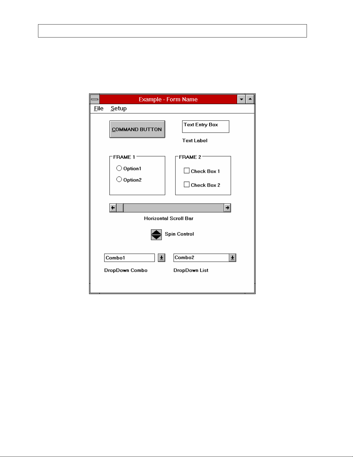
performed will consist of one or more dialog boxes, as shown in Figure 3-1. Each screen will
have various controls on it which perform functions when clicked with the pointing device
(mouse or trackball) or when selected from the keyboard. When you are finished with all of
the tasks on a given screen, selecting the D
previous screen.
ONE or EXIT control button will return you to the
WINDOWS CONTROLS
The most common Windows controls are described below. When controls are selected they
cause functions or actions to be performed. A control can be selected in several ways; the
most common way is with the pointing device (mouse or trackball). A control is selected by
positioning the trackball cursor over the control and clicking the left trackball button. The
trackball cursor takes several different shapes depending on what is going on in the program
and where it is on the screen. Most controls can also be selected through the keyboard.
The Tab key on the keyboard is used to move from one control to another. Pressing Shift-
Tab will move back one control. Once a control is selected it can be activated, or changed
with other keys. The specific keys which affect each type of control are discussed below.
Trackball Cursor
The trackball indicator is used to select items on the screen. Most of the time the cursor
appears as an arrow with a black outline filled with white. When the system is busy doing
something that will prohibit it from responding the cursor changes to an hourglass. When in
MCA mode, and the cursor is within the boundaries of the spectrum display, the cursor
changes to a double ended vertical arrow Ú.
July 00 GENERAL OPERATING INSTRUCTIONS 3-1
Page 28
CAPINTEC, INC CAPTUS® 2000
When the cursor is located within a text box it will change to a thin vertical "I-beam." Note
that actually having the ability to input or edit requires that you click the trackball button to
cause the edit cursor, a bold blinking vertical line, to appear.
Figure 3-1
Command Button
The most common control in the CAPTUS
®
2000 is the command button. An example of a
command button is shown in Figure 3-1. A command button can be activated in one of three
ways:
1. positioning the pointing device over the button and clicking the pointing device's left
button once,
2. using the Tab key on the keyboard to move the high light from control to control until
the desired control is highlighted, then press the Enter key, or
3. holding down the Alt key and pressing the letter in the command button caption which
is underlined. (in Figure 3-1 this would be Alt-C).
3-2 GENERAL OPERATING INSTRUCTIONS July 00
Page 29

CAPINTEC, INC CAPTUS® 2000
Activating a command button will cause it to perform the specified function. This may involve
additional dialog boxes or various other modes of interaction with the user.
Frame
A frame groups various controls together into a logical group. Any type of control may be
located within a frame. The only control type which is affected by being in a frame is the
radio button.
Radio Button
Radio buttons are used to select options. They are called radio buttons because they
behave like the selector buttons on a car radio – only one of the buttons in a group
may be true at a time.
A button may be selected in two ways:
1. positioning the pointing device over the desired button and clicking one time,
or
2. by using the Tab key to select a set of buttons and then using the up and
down arrow keys ( ) to move from one button in the group to another.
Check Box
Check boxes are also used to select or enable various options; however, check
boxes work as individual controls not in groups. When a check box is true an "X" will
appear in the box. (Note that for Windows 95, a check mark will appear.)
A check box may be selected in two ways:
1. positioning the pointing device over the desired button and clicking one time
will activate the box, clicking again will deactivate the box, or
2. by using the Tab key to select a box and then using the space bar to activate
or deactivate the box.
Text Entry Box
The text box is used whenever input of numeric or alphanumeric information is required.
A text box can be selected in one of two ways:
1. positioning the pointing device over the box and clicking the pointing device's left
button once, or
2. using the Tab key on the keyboard to move from control to control until the desired
text box is highlighted or the cursor appears in the text box.
In the CAPTUS
®
2000, most text boxes will highlight in red when they are selected. (Note
that for Windows 95, the text will appear white with a blue background.) When a box is
highlighted, typing will replace the highlighted information and the previous contents will be
lost. If you wish to edit the existing information use either the left or right arrow ( ) to
move the cursor to the appropriate location. As soon as the cursor moves the highlight will
July 00 GENERAL OPERATING INSTRUCTIONS 3-3
Page 30
CAPINTEC, INC CAPTUS® 2000
be removed. The contents of the text box can then be edited. The following control keys are
active during editing:
Delete Deletes the character after the cursor
Backspace Deletes the character before the cursor
Right Arrow Moves one character to the right
Left Arrow Moves one character to the left
End Moves to the end of the input
Home Moves to the beginning of the input
Some text input boxes provide input verification. If the information typed in the box is invalid,
i.e. does not match the requested format (for example, an input in a box requesting a date of
13/45/92) or falls outside the range of valid values, a warning message will be given and the
user will be forced to edit or re-input the information.
When the information in a text box is highlighted in blue (or gray for Windows 95) it indicates
that the data is provided by the system and cannot be edited by the user.
There is one special type of text box which is used in the CAPTUS
comments which will appear on test reports. These comment boxes generally appear on the
bottom of the "EDIT" form associated with each test. In these boxes up to 8,000 characters
of text may be entered. Within the box, text will automatically wrap from one line to the next
as it is typed in. The user may also move to the next line by using the Enter key. Ctrl-Tab
causes a tab to be entered into the text and the cursor to move to the next tab position
(remember pressing just Tab will move you to the next control).
®
2000 for input of
Scroll Bars
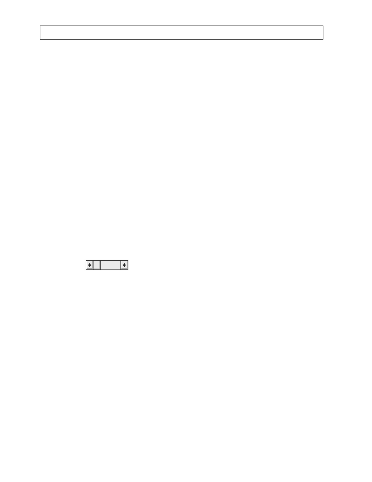
There are two types of scroll bars, horizontal and vertical. They are used to change the
value of some parameter within the program. The CAPTUS
®
2000 uses scroll bars in its
MCA section to control what section of a spectrum is being viewed.
When using the pointing device to manipulate a scroll bar there are a number of actions
which will cause the bar to change. Clicking the arrow at an end of the bar will cause the
"value" of the scroll bar to change in that direction by an amount referred to as a small
change. Clicking the bar itself at any location between the end arrow and the slider will
cause the value to change in that direction by an amount referred to as a large change
(usually 8 to 32 times the amount of a small change). The slider may also be moved by
placing the cursor on the slider, pressing the left pointer button down and holding it there
while you "drag" the slider to the desired position.
The scroll bar may also be adjusted from the keyboard. The scroll bar is activated through
the Tab key. When it is active the slider will blink. The slider can then be positioned using
the following keys:
Up Arrow Moves the slider a small change up or to the right
Right Arrow Moves the slider a small change to the right or up
Down Arrow Moves the slider a small change down or to the left
Left Arrow Moves the slider a small change to the left or down
3-4 GENERAL OPERATING INSTRUCTIONS July 00
Page 31

CAPINTEC, INC CAPTUS® 2000
Home Moves the slider all the way to the left or down
End Moves the slider all the way to the right or up
Spin Control
The spin control is also used to adjust values such as the high voltage on the MCA form.
The control consists of two back to back arrows. Clicking an arrow with the cursor causes
the value under control to change in the specified direction. The spin button can only be
controlled with the pointing device.
List Controls
There are two types of "list" controls used in the CAPTUS
®
2000. Both appear quite similar
on the screen. The only difference in appearance is that on the Drop Down Combo control,
the arrow is not attached to text box portion, while on the Drop Down List control, the arrow is
attached. In function both controls are similar except for one item. On the Drop Down
Combo control the user can either enter new data directly into the text box or select from the
list. In the Drop Down List control the user can only select from the list.
To select an entry from the list, use the trackball left button to click the down arrow. The list
will appear. If there are more items on the list than can be shown vertical scroll bars will
appear on the right edge of the list. Place the pointer over the desired entry and double-click
the left trackball button. The box will retract and only the selected item will be displayed.
Once the control is selected the up and down arrows may also be used to scroll through the
list of items.
Menu Bars
Across the top of many forms you will find a menu bar. In the example the menu bar
contains two items: F
ile and Setup. These are referred to as the top level menu items. A
menu item can be selected either with the trackball or by typing Alt-K where K is the letter
underlined in the name of the menu item. In some cases the top level menu item causes
action to be taken immediately. In other cases selecting it will cause another dialog box to
appear. Selecting an item in the same way is then necessary.
Keyboard Control
Most commands or actions can also be activated by keyboard strokes. The command
buttons and menu bar items are all controlled from the keyboard in the same manner. Each
word has one letter underlined. By holding the Alt key down, and then pressing the
underlined letter on the keyboard, the selection is activated. Almost every action in the
CAPTUS
®
2000 can be accomplished from keyboard control in this manner.
July 00 GENERAL OPERATING INSTRUCTIONS 3-5
Page 32

CAPINTEC, INC CAPTUS® 2000
Switching to Other Windows Applications
Instead of closing down a Windows Application, you can switch to other Windows
applications by using certain key sequences. (In previous software versions, exiting the
CAPTUS
the detectors.)
In Windows 3.1, switching to another application can be performed in two ways. One way is
to press down and hold the Ctrl key and then press the Esc key. This will bring up a Task
List or Task Manager Window with a list of all the other applications that are running. Select
the application that you wish to open by double clicking on it or using the SWITCH TO
command button. The other way is to press and hold down the Alt key and then press the
Tab key. A gray window containing an application icon will appear. While still holding the Alt
key, press the Tab key until the desired icon is shown. Let go of the Alt key to switch to the
Windows application. You can then switch back to the CAPTUS
one of these two methods.
In Windows 95, switch to another application by pressing the Windows key at the bottom of
the keyboard or holding down the Ctrl key and pressing the Esc key. You will then be able to
use the trackball to switch to a new program or to open applications at the bottom of the
screen. You can switch back to the CAPTUS
by holding down the Alt key and pressing the Tab key. A gray window containing the icons
of all the open applications will appear. While still holding down the Alt key, press the Tab
key until the CAPTUS
®
2000 program would shut off the high voltage power supply to the MCA board and
®
2000 program by using
®
2000 program by using the same method or
®
2000 icon is outlined and then let go of the Alt key.
3-6 GENERAL OPERATING INSTRUCTIONS July 00
Page 33

CAPINTEC, INC CAPTUS® 2000
CHAPTER 4
SYSTEM SETUP
INSTALLATION
Your system has been shipped from the factory pre-configured and fully tested. Installation
consists of placing the components on the stand and securing them in place as shown in the
“CAPTUS 2000 SPRING-ARM STAND UPACKING AND ASSEMBLY INSTRUCTIONS“
(P/N 5432-5061) document.
ENVIRONMENT REQUIREMENTS
Operational
The instrument should be located where the level of the background radiation is as low and
as constant as possible.
The instrument should be located where the temperature is stable within a range of +50°F to
+85°F (+10°C to +30°C) and the maximum relative humidity is 90% non-condensing to
warrant maximum reliability and accuracy.
The instrument should be located where the barometric pressure is within a range of 27 – 31
inches of mercury (91 – 105 kilopascals).
Storage
The instrument should be stored where the temperature is stable and the range is from
+39°F to +115°F (+4°C to +43°C) and the maximum relative humidity is 90% non-condensing
to warrant maximum reliability.
The instrument should be stored where the barometric pressure is within a range of 15 – 33
inches of mercury (51 – 112 kilopascals).
CAUTION
If these environmental requirements are not followed, the instrument may display erroneous
readings.
POWER REQUIREMENTS
CAUTION
If the input voltage to the following items is not within the stated limits, the unit may not
function correctly or may be damaged.
July 00 SYSTEM SETUP 4-1
Page 34

CAPINTEC, INC CAPTUS® 2000
Standard 115V* 105-127V 1.3 Amps 50/60Hz
Optional 100V* 90-110V 1.5 Amps 50/60Hz
Optional 230V* 210-255V 0.8 Amps 50/60Hz
Optional 200V* 180-220V 1.0 Amps 50/60Hz
TURN ON PROCEDURE
Once the system components are mounted securely and all cables are connected you are
ready to turn the system on. There are three power switches associated with the system:
1) the monitor has a power switch, 2) the computer has a power switch, and 3) the printer
has a power switch. Turn on all three switches.
Your system will power up, go through the computer boot up sequence, and display the
Windows
CAPTUS 2000
measurements, allow the system to warm up at least 30 minutes. It is recommended that the
system be left on with the CAPTUS
powered whenever the CAPTUS
optimal viewing under lighting conditions at your facility.
®
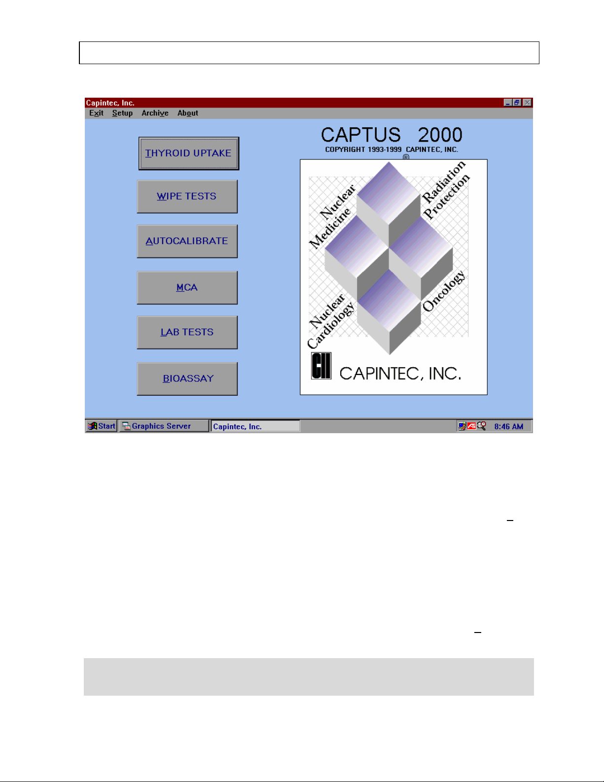
start up screen. To run the CAPTUS® 2000 software, double click on the
®
icon. Figure 4-1, the main menu screen, will appear. Before beginning any
®
2000 program running because the MCA board is
®
2000 software is running. Adjust the monitor display for
4-2 SYSTEM SETUP July 00
Page 35
CAPINTEC, INC CAPTUS® 2000
®
Figure 4-1 CAPTUS
2000 Main Menu
GENERAL OPERATIONAL SETUP
®
The software version installed on your CAPTUS
from the menu bar located at the top of the main menu screen. Information concerning the
software version cannot be altered by the user. Any software upgrades will automatically
change the version number accordingly.
The CAPTUS
®
2000 has system operating parameters and reference information which is
contained in the System Setup module. The Setup module contains System Parameters,
Normal Values, Isotope Library, and Reference Standards. Many parameters have been
predefined or supplied with default values. However, you may change these parameters or
enter different values. The System Setup module may be accessed by selecting S
the menu bar located in the top of the CAPTUS
NOTE: Before beginning any measurements in the Setup module, follow the Quality
Assurance Procedures outlined in Chapter 5 to insure correct operation of the CAPTUS®
2000.
2000 can be identified by selecting About
®
2000 Main Menu screen.
etup from
July 00 SYSTEM SETUP 4-3
Page 36
CAPINTEC, INC CAPTUS® 2000
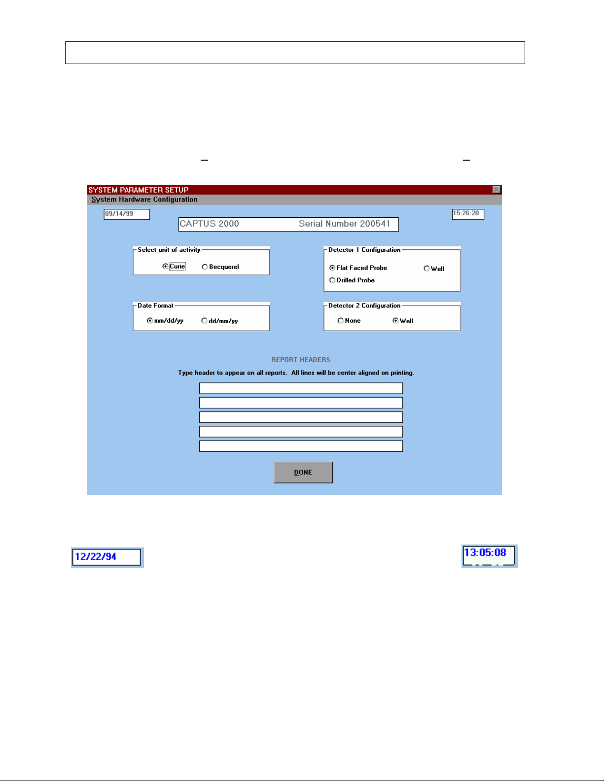
SYSTEM PARAMETERS
The System Parameters module displays the date, time, system serial number, units of
activity, detector configuration, date format and report header. To access information about
system parameters, select S
The system parameter setup screen will appear as shown in Figure 4-2.
ystems Parameters... from the drop down list under Setup.
Figure 4-2
Figure 4-3
The date and time used in the CAPTUS
displayed throughout the system, Figure 4-3. Note that the transition from 1999 to the year
2000 will not be a problem with the CAPTUS
®
2000 software are taken from the computer, and
®
2000 software because it utilizes a four digit
year in its calculations.
Reference the documentation which came with the computer for changing the date and time.
4-4 SYSTEM SETUP July 00
Page 37
CAPINTEC, INC CAPTUS® 2000
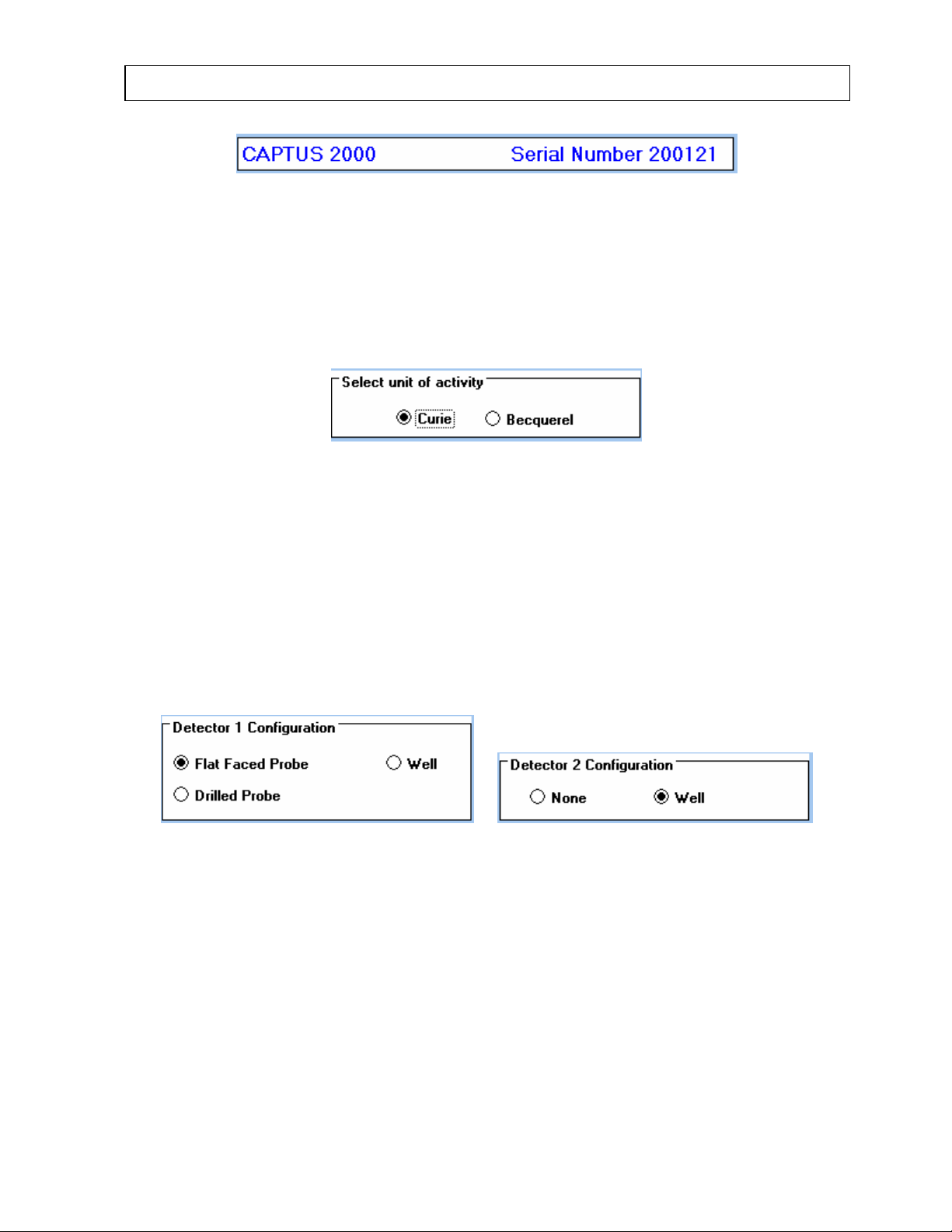
Figure 4-4
The serial number of your CAPTUS
Figure 4-4, and cannot be altered by the user. It should be used as a reference together with
your software version when contacting the CAPINTEC Service Center for information or
assistance.
You may choose either Curie or Becquerel units of activity. To change units, use the
trackball to position the pointing device over the unit of activity selection box, Figure 4-5, over
the correct radio button and click , or use the Tab key to select the correct option box and
use the up and down arrow keys to move from one radio button in the group to the other.
You can safely change the unit of activity at any time during the use of your system. All
activity values, including stored values, will automatically be converted and displayed in the
selected units. Note that count rate always appears as cpm, or counts per minute,
regardless of units of activity chosen.
®
2000 system is displayed in the serial number view box,
Figure 4-5
Figure 4-6
Your detector configuration has been defined for the correct hardware shipped with your
system. If you need to change your configuration, use the trackball to position the pointing
device over the detector configuration box, Figure 4-6, and click, or use the Tab key to select
the correct option box and use the up and down arrow keys to move from one radio button in
the group to the other.
July 00 SYSTEM SETUP 4-5
Page 38
CAPINTEC, INC CAPTUS® 2000
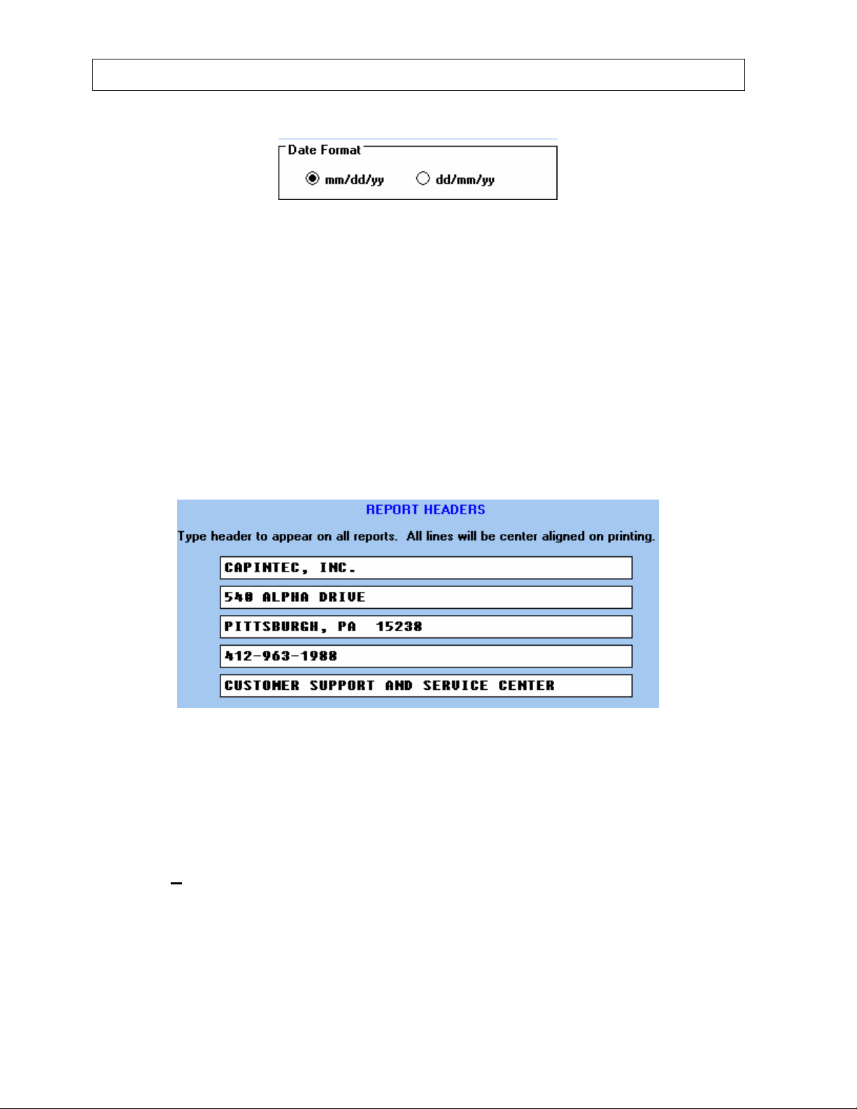
Figure 4-7
The date may be entered in either mm/dd/yy or dd/mm/yy format through the CAPTUS
software. To change date format, select the Date Format box, Figure 4-7, use the trackball
to position the pointing device over the correct radio button and click, or use the Tab key to
select the correct option box and use the up and down arrow keys to move from one radio
button in the group to the other.
NOTE: The date format must be set before entering any dates in the measurement mode.
Changing the date format does not alter previously stored information! If data has already
been saved, and you change the date format, a warning message will appear stating “All
patient and test data will be lost if you change the date format! Are you sure you want to
change the date format?” Select YES to change the date format and lose all stored data,
select NO to exit without changing the date format.
®
2000
Figure 4-8
The CAPTUS
®
2000 software will print up to five lines of header information on all printed
reports. You will have to enter your facility name and address as shown in the example in
Figure 4-8. To input your facility information, point to the appropriate line and click to select.
Type from the keyboard and the new information will appear. All lines will be center aligned
upon printing, and will appear on all printed reports. To exit the System Parameters module
select the D
ONE button and you will return to the Main Menu screen of the CAPTUS® 2000
software.
4-6 SYSTEM SETUP July 00
Page 39
CAPINTEC, INC CAPTUS® 2000
NORMAL VALUES
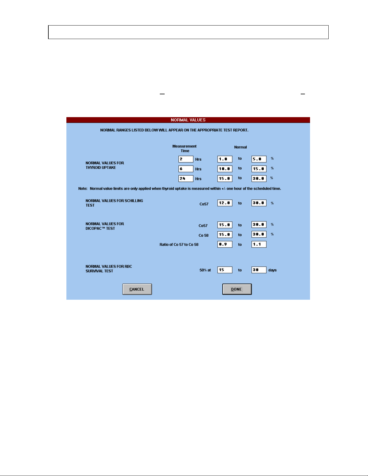
The Normal Values module stores normal values for percent Thyroid Uptake, Schilling Test,
DICOPAC
®
Test, and RBC Survival Test. Normal value ranges are listed on the printed
result reports, and any patient results which exceed these ranges are flagged. To input
information for normal values, select N
ormal Values... from the drop down list under Setup.
Figure 4-9 will appear.
Figure 4-9
NOTE: The normal values shown above are for demonstration purposes only and are not
suggested by CAPINTEC for clinical use.
To enter normal value ranges, place the arrow over the desired box and click. Then type in
the correct value. Note that all percent values must be a number between 1 and 100.
For Thyroid Uptake you may enter up to three normal value ranges in percent for three
different times after administration of the dosage. Enter the time in hours and the uptake
result in percent. Note that the normal value ranges will only apply to thyroid uptakes which
are measured within ±1 hour of the stated normal value range. Uptake results outside the
normal value range for other times will not be flagged.
July 00 SYSTEM SETUP 4-7
Page 40
CAPINTEC, INC CAPTUS® 2000
The Schilling Test normal value range stores values for the percent of Cobalt 57 which has
been excreted in a patient’s urine.
The DICOPAC
®
Test normal value range stores values for the percent of Cobalt 57 and
Cobalt 58 which have been excreted in a patient’s urine, and the ratio of Cobalt 57 to Cobalt
58.
The RBC Survival Test normal value range stores a value for the time period in days when
50% of tagged red blood cells remain.
To exit and save the Normal Values information entered, select the D
will return to the Main Menu screen of the CAPTUS
®
2000 software. Selecting the CANCEL
ONE button and you
button will exit the Normal Values screen without saving entered data.
REFERENCE STANDARDS
The Reference Standards module stores calibration information on reference standards. The
module is only a data base for information. No MCA functions are active in Reference
Standards. The information entered is accessed in the Isotope Library module for
radioactive decay correction, efficiency measurements and calibration. To enter information
on your reference sources, select R
S
etup. Figure 4-10 will appear.
eference Standards... from the drop down list under
Figure 4-10
4-8 SYSTEM SETUP July 00
Page 41

CAPINTEC, INC CAPTUS® 2000
The Reference Standard calibration information that appears for the Cesium 137 and
Europium 152 sources will not correspond to the information for the rod sources
provided with your system. The information that appears corresponds to the sources used
by the Capintec Service Center when setting up and testing your system. You will have to
edit the calibration information so that it corresponds to your rod sources. The reference
standard information is necessary to measure the efficiency of the source in the Isotope
Library. For each reference standard, the Reference Standard database stores the name,
isotope, date, time, activity, and serial number of your reference source.
To enter information on a new standard, select the A
blank text boxes. Enter the name or serial number in alphanumeric characters. It may be
helpful to include the source activity in name, especially when two or more reference
standards of the same isotope are listed. Select the desired isotope from the isotope drop
down box. Over 60 isotopes are listed. Half life and energy emission information for the
isotopes on the list are stored in memory for radioactive decay and peak identification
programs. Enter the calibration date, the calibration time, and the activity of the standard at
the time it was calibrated. To save the information entered, select the D
the screen without saving, choose the C
ANCEL button.
To modify stored information, select the E
DIT button. The information previously entered for
the selected standard will appear. Change the listed information by selecting the appropriate
text box with the arrow and clicking. The information will be highlighted. New information will
type over the listed characters. To save the information entered, select the D
To exit the screen without saving, choose the C
To delete an entry, select the desired reference standard from the standard name drop down
list. Once the desired standard has been selected, choose the D
which reads “Are you sure you want to delete this reference standard?” will appear. To delete
the displayed standard, choose Yes, to abort the delete command choose No.
Select the P
RINT LIBRARY button to print the reference standard information stored in the
library. The isotope, name, and calibration information will be printed.
To exit the reference standards library module, select the D
return to the CAPTUS
®
2000 Main Menu screen.
DD button. Figure 4-10 will appear with
ONE button. To exit
ONE button.
ANCEL button.
ELETE button. A message
ONE button. The software will
July 00 SYSTEM SETUP 4-9
Page 42
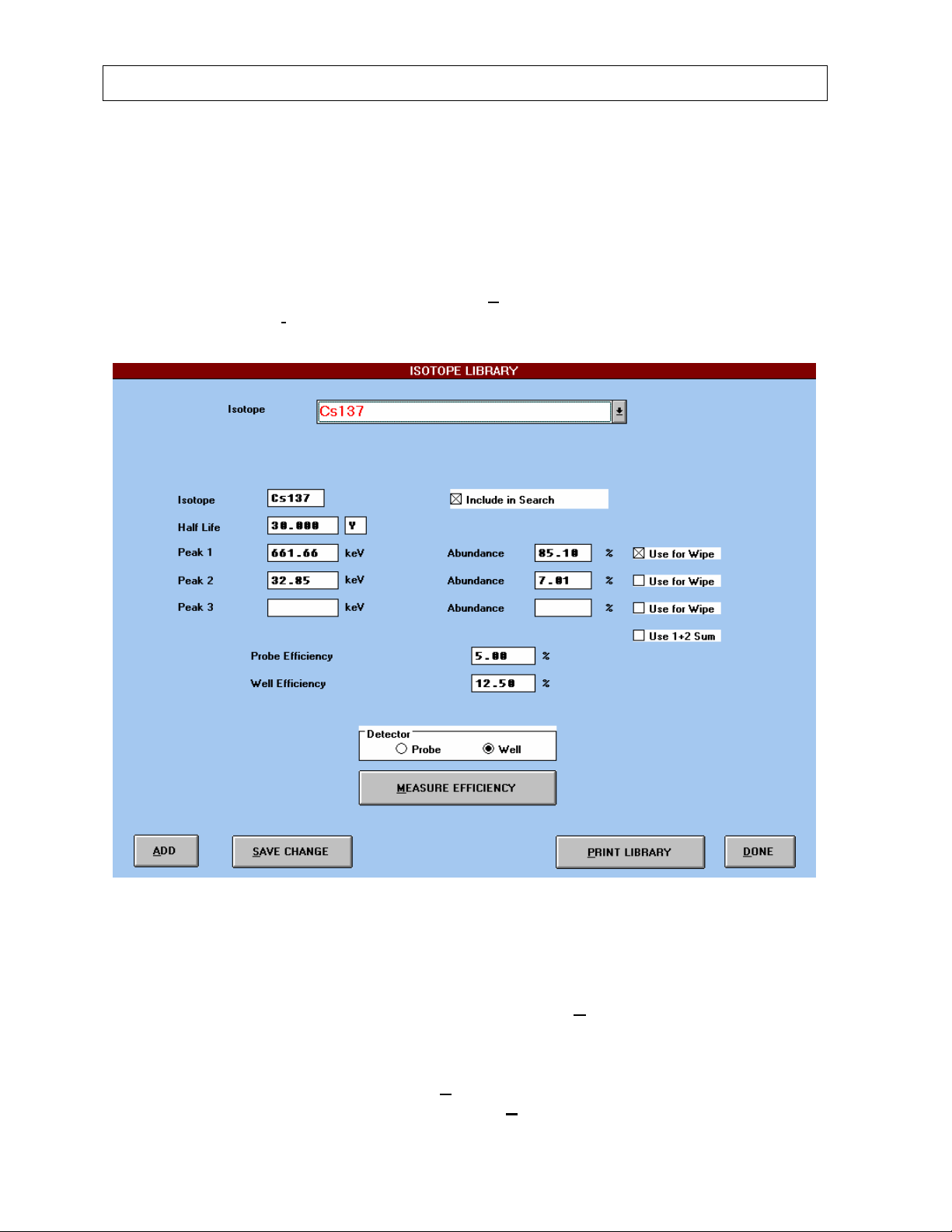
CAPINTEC, INC CAPTUS® 2000
ISOTOPE LIBRARY
The CAPTUS® 2000 has an extensive reference library of isotope information which includes
the name, half life, major energy peaks, and percent abundance for over 60 isotopes. For
those isotopes which exhibit significant sum peak formation in a well geometry, notably
Barium 133 and Indium 111, the sum peak has also been added. The user may add
isotopes as required to this reference list. This information is used in the identification of
isotope peaks in MCA or wipe test mode, radioactive decay corrections, and measurement of
efficiencies. To access the isotope library, select S
screen. Then choose I
sotope Library from the drop down list. Figure 4-11 will appear.
etup from the menu bar of the main menu
Figure 4-11
ENTERING ISOTOPE INFORMATION
To add an isotope which is not listed in the library, select the ADD button. A screen similar
to Figure 4-12 will appear with blank text boxes. Enter the correct isotope information in the
appropriately labeled text boxes. Review the information to insure that it is correct.
To add the isotope to the library, select the S
saving any data to the reference library, choose the C
4-10 SYSTEM SETUP July 00
AVE button. To exit the add screen without
ANCEL button.
Page 43

CAPINTEC, INC CAPTUS® 2000
×
To edit previously stored information, select the isotope from the isotope drop down box, and
Tab or click on the desired text box, and enter the changed data. To save this new
information to the isotope library, choose the S
AVE CHANGE button. If you select DONE to
exit the isotope library without saving changes, the following message will appear, “Isotope
information has been changed. Save changes before exit?” To save the changes and exit,
choose Yes. To exit without saving changes, select No.
EFFICIENCY MEASUREMENTS
Throughout the measurement process, counting losses occur from the placement of the
source in relation to the detector, energy and intensity of the photon measured, speed of
detector response, and size and shape of the detector. As a result, the actual number of
pulses measured by the system are always less than the number of radioactive emissions
emitted by the source. The ratio of counts or count rate measured to radioactive emissions
or activity (radiation rate) emitted is a unitless number termed efficiency, which is
conventionally reported as a percent.
dpm
100 cpm
EASURE EFFICIENCY button.
®
2000 software. The
= Efficiency %
Once the efficiency of an isotope is measured, then count rate can be converted into activity.
Your CAPTUS
®
2000 has the ability to measure, calculate, and store in memory efficiencies
for any isotope listed in the isotope library. The software will then automatically convert the
count rate of isotopes identified by the peak finding algorithm into activity.
Efficiencies can be measured in the add isotope screen, or the main isotope library screen.
The procedure is the same for both modules. Before beginning the measurement process,
select the correct detector from the detector option box. To measure the efficiency of an
isotope, first obtain a calibrated source. Then select the M
Figure 4-13 will appear.
Many long lived isotopes are available commercially. CAPINTEC can also provide reference
source information. For the well counter, choose an activity less than 2 µCi. For the uptake
probe detector, insure that the counting rate does not exceed 20% dead time. You can find
the percent dead time by counting in the MCA mode of the CAPTUS
percent dead time will appear in the upper right corner of the MCA screen.
NOTE: You should re-measure the probe and well efficiencies that correspond to your
Cesium 137 standard reference source. You will need these efficiencies to accurately
perform the Constancy Test. The Cs137 efficiencies that are originally listed were measured
with the source used at the Capintec Service Center and may not be the same as the
efficiencies of your source.
July 00 SYSTEM SETUP 4-11
Page 44
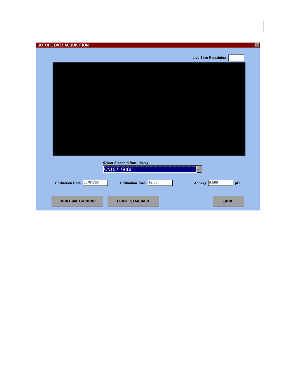
CAPINTEC, INC CAPTUS® 2000
Figure 4-12
The isotope drop down list will display all of the sources of the specified isotope that were
entered into the reference library data base . If a standard for the desired isotope standard is
not listed, select Other from the drop down list. Figure 4-13 will appear.
4-12 SYSTEM SETUP July 00
Page 45
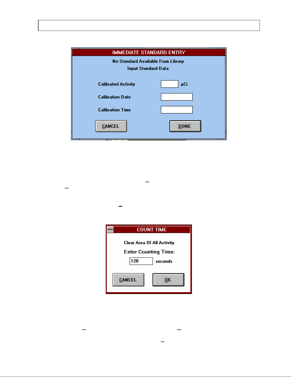
CAPINTEC, INC CAPTUS® 2000
Figure 4-13
Enter the calibrated activity, calibration date, and calibration time for the source. The
software will automatically decay correct the source to the current activity. To exit the screen
without saving the source information, select C
select the D
ONE button.
Once the source information has been determined, begin the efficiency measurement
process by selecting the COUNT B
ACKGROUND button. Insure that no sources are near
the detector. The pop up screen shown in Figure 4-14 will appear and request counting time.
ANCEL. To save the source information,
Figure 4-14
Enter the appropriate counting time. The system default is 120 seconds. To exit without
measuring select C
ANCEL. Confirm the time by selecting OK. Then the system will
automatically begin the background count. To stop the count and save the counting data
before the preset live time has elapsed, choose the S
July 00 SYSTEM SETUP 4-13
TOP & SAVE button.
Page 46
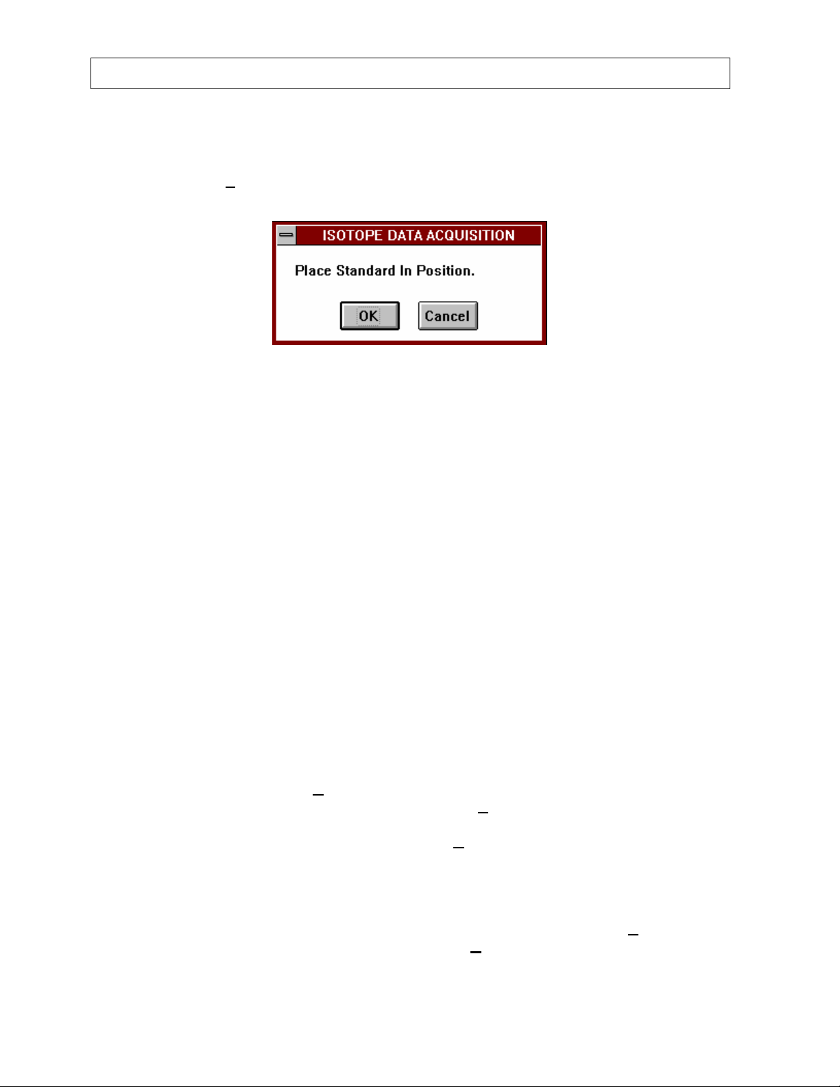
CAPINTEC, INC CAPTUS® 2000
When the background count is completed, DONE will appear in the spectral display area.
After the background count has been completed, place the source in the desired position and
select the COUNT S
After the standard has been properly positioned, select OK to begin counting. Choose
Cancel to exit without counting the source. Remember that efficiency measurements are
dependent upon source geometry. Subsequent measurements of unknown activities of the
same isotope must be placed in the same position as the reference source in order to
accurately determine activity. You may wish to make a note of the source to detector
distance for efficiencies measured with the probe detector.
As the measurement begins and counts are acquired, the live spectra will be displayed on
the screen. The live time remaining will be displayed in the upper right corner. Vertical scale
counts will be displayed in the upper left corner. At the end of the source count, the ROI
around the photopeak used to determine the efficiency will be highlighted in red. Note that
the efficiency is calculated from a ROI which is defined as the FWTM (full width-tenth
maximum) of the primary photopeak only, and not whole spectrum counts. This may result in
calculated efficiency values which are lower than you may be used to seeing for common
isotopes measured with 2” by 2” NaI detectors. This is done so that activities can be
accurately determined even in samples with more than one isotope. If you wish to calculate
a whole spectrum efficiency for comparison with other similar detectors, count the source in
the MCA mode. Use the total spectrum counts, and manually divide the count rate by the
current decay corrected activity of the source.
When the count is complete, DONE will appear in the spectrum display area. To stop the
count without saving, select the A
data before the preset live time has elapsed, choose the S
isotopes can be measured without exiting the efficiency measurement screen. After
completing your efficiency measurements, select the D
return to the main isotope library screen. The measured efficiency will be displayed in the
appropriate detector box. Note that the efficiency for a source must be measured
independently for each detector in a two detector system.
To print a complete list of all information stored in the isotope library, select the P
LIBRARY button. To exit the isotope library, select the D
return to the CAPTUS
TANDARD button. Figure 4-15 will appear.
Figure 4-15
BORT button. To stop the count and save the counting
TOP & SAVE button. Additional
ONE button, and the software will
RINT
®
2000 main menu screen. Figure 4-16 lists the isotope library report.
ONE button. The software will
4-14 SYSTEM SETUP July 00
Page 47
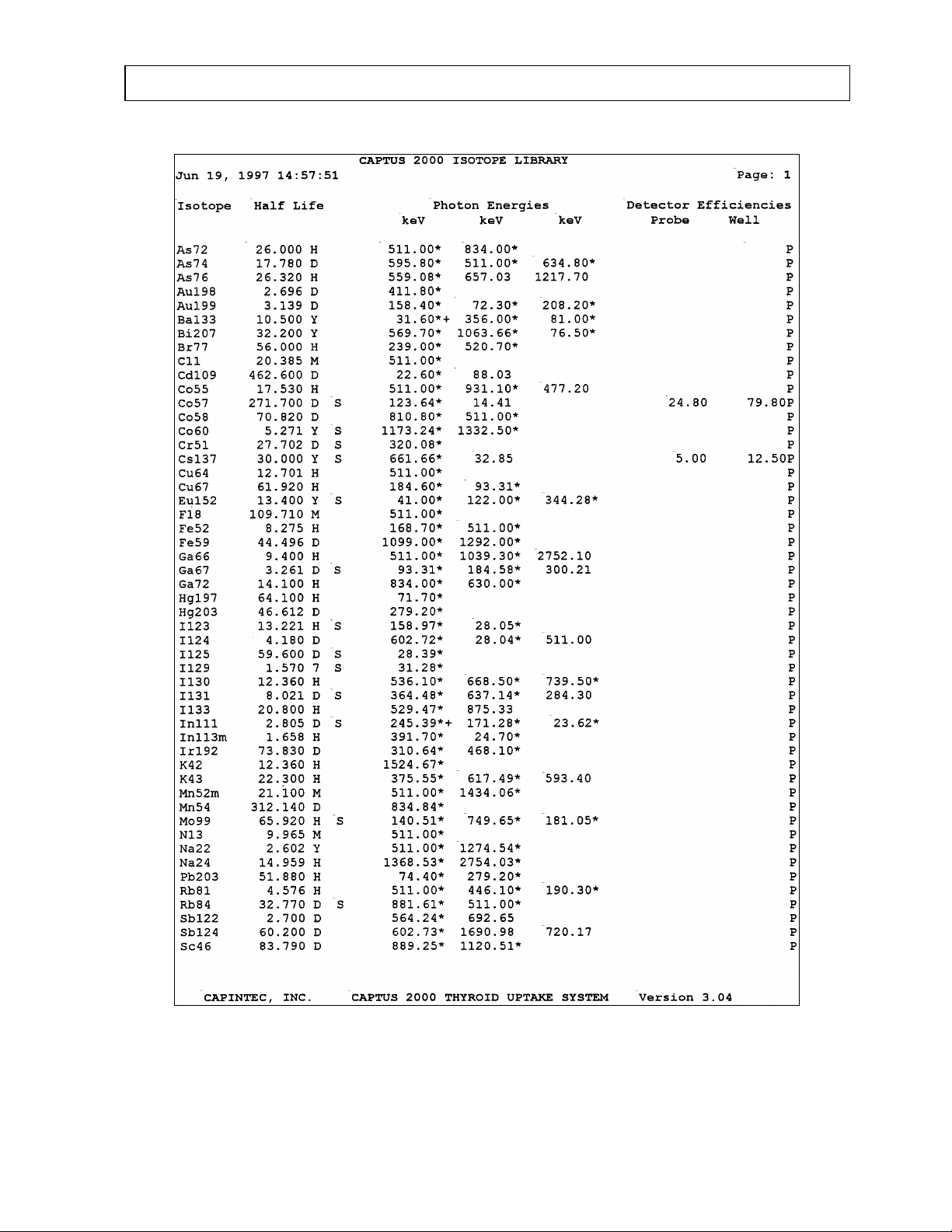
CAPINTEC, INC CAPTUS® 2000
Figure 4-16
July 00 SYSTEM SETUP 4-15
Page 48
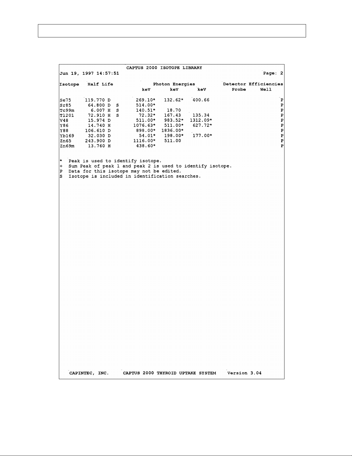
CAPINTEC, INC CAPTUS® 2000
4-16 SYSTEM SETUP July 00
Page 49
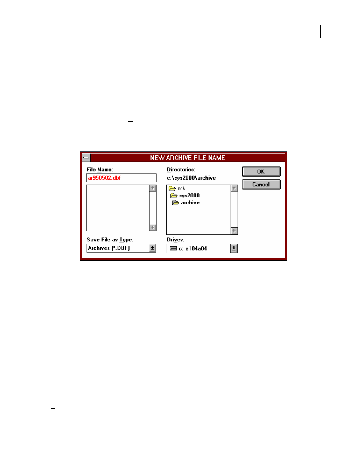
CAPINTEC, INC CAPTUS® 2000
ARCHIVE FILES
The CAPTUS® 2000 software provides the user with an archive file feature to easily save all
current data files at one time. The files can be sorted by test group for selective printing.
Archiving can be periodically performed to provide a system backup or before deleting non
active files. Note that archived files are only available for report printing. They cannot be
accessed for editing or additional data collection.
Select the A
Menu screen. Then select C
will be listed as arYYMMDD.dbf where YYMMDD is the current date in year, month, day, and
.dbf is the data base file extension.
rchive command located at the top of the menu bar on the Main CAPTUS® 2000
reate Archive. Figure 4-17 will appear. The default file name
Figure 4-17
Use this default name, or enter a different file name following MS-DOS filename conventions,
up to eight alphanumeric characters with a period separating a three character extension.
The CAPTUS
®
2000 will default to the c:\SYS2000\archive directory with a ".dbf" extension.
To save the data to floppy disk, first select the correct drive from the Drives list, and enter the
desired file name. To exit the screen and cancel the save, choose the Cancel button. To
continue with the archive procedure for the current data base files, choose the OK button.
This will store the archived files in memory and exit the archive file name screen. All data
files currently available will be copied and stored to the archived file. During the archive
process, the module name and number of files will be displayed as each file is saved.
Archived information consists of all patient tests (Thyroid Uptake, Schilling, Dicopac, Blood
Volume, and RBC Survival), bioassay staff data, the wipe history reports (grouped by
location), and the Autocalibration history.
Figure 4-18 will appear upon completion to confirm the success of the archive process. Note
that this does not indicate current files have been deleted. To delete files, you must choose
D
elete All for each individual clinical group.
July 00 SYSTEM SETUP 4-17
Page 50
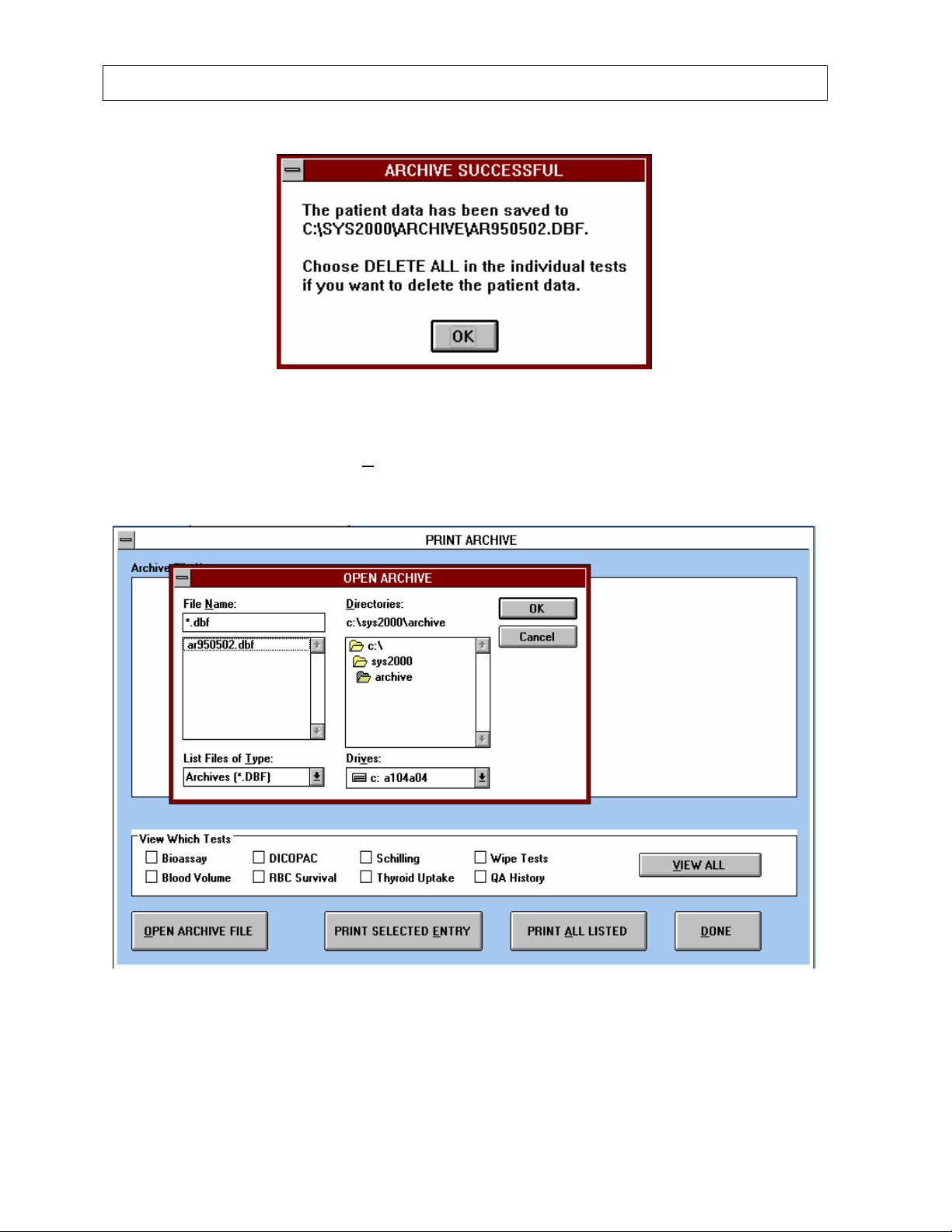
CAPINTEC, INC CAPTUS® 2000
Figure 4-18
To print archived files, select the P
Figure 4-19 will appear.
rint Archive selection for the Archive command list.
Figure 4-19
First open the archive file by selecting the correct file name from the listed .dbf files. Select
Cancel to exit the archive screen and return to the Main CAPTUS
®
2000 Menu screen.
Select OK to open the archive file. The “Open Archive” window will disappear, and the list of
4-18 SYSTEM SETUP July 00
Page 51
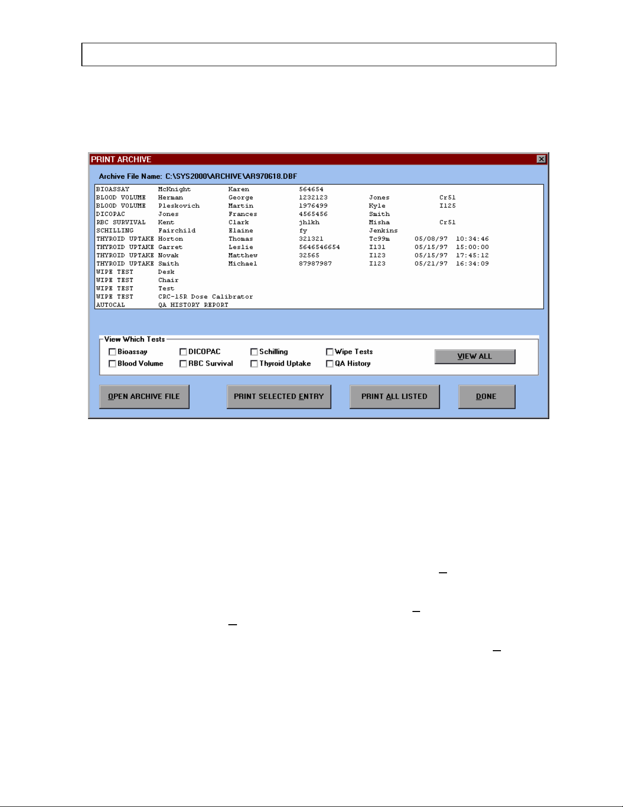
CAPINTEC, INC CAPTUS® 2000
all individual files in the archive file will appear in the viewing area listed in alphabetical order.
Select the desired archived file and then select OK. The PRINT ARCHIVE window, Figure
4-20 will appear.
Figure 4-20
The files will be grouped by clinical module first, e.g. bioassay, blood volume, DICOPAC
®
,
etc., then by individual name and ID number. Wipe tests are grouped by location. Use the
scroll bar located at the right of the viewing area to scroll through the file list. If the list is very
long, choose the test groups of interest by selecting the box to the left of each group. An X
or check mark will appear in the box, and those files not selected will disappear from the
viewing area.
To print all of the tests displayed in the viewing area, select the PRINT A
LL LISTED button.
A complete individual report of all data for each person or test will be printed. To print only
one individual, select the desired file by using the trackball indicator. The file name and ID
number will be highlighted. Then choose the PRINT SELECTED E
new archived file, select the O
PEN ARCHIVE FILE button.
NTRY button. To open a
After printing the archived files of interest, exit the archive screen by selecting the D
button, and return to the Main CAPTUS
®
2000 screen.
ONE
July 00 SYSTEM SETUP 4-19
Page 52

Page 53

®
CAPINTEC, INC CAPTUS
2000
CHAPTER 5
QUALITY ASSURANCE
WARM UP
If your system will be used in a single location we recommend that you leave the computer
powered at all times. This will minimize warm up problems and will provide the lowest wear
and tear on the system. The MCA board is powered whenever the computer is turned on
and the CAPTUS
MCA board will remain powered until the computer is shut off or rebooted. If you are going to
leave the computer on, we suggest that at the end of the day you turn off the monitor and
printer. If you would prefer to turn off the entire system each evening, then allow at least 30
minutes for system warm up before performing any calibration procedures or making any
measurements.
There are several quality assurance tests which should be periodically performed on the
CAPTUS
calibration, constancy, reproducibility (chi-squared test), and crystal resolution, all of which
the CAPTUS
sources provided with the system. The calibration and constancy test should be performed
daily, while chi-squared and detector resolution tests should be performed at least quarterly.
For systems with two detectors, e.g. uptake probe and well counter, the calibration and test
procedures must be performed on both detectors. The software automatically saves the
calibration information for each detector in memory. Whenever the detector input is
changed, the software automatically resets the calibration parameters accordingly. This
insures proper operation of the system at all times.
Note that if you use a drilled probe, you should calibrate both the probe and well, even
though there is only one detector. Each software module uses the calibration parameters of
the particular detector that is associated with it. For example, the thyroid uptake program
uses the calibration parameters of the probe, and the wipe test program uses those of the
well.
®
2000 system to insure proper operation and calibration. These include energy
®
2000 software is running. If you exit the CAPTUS® 2000 software, the
®
2000 performs quickly and automatically using two dedicated reference
DAILY TESTS AND CALIBRATION
In order to access the automatic testing and calibration module, choose the
A
UTOCALIBRATE button on the main menu screen. The autocalibration screen, as shown
in Figure 5-1, will appear. Select the correct detector (probe or well) to calibrate by placing
the indicator arrow over the detector button and clicking.
July 00 QUALITY ASSURANCE 5-1
Page 54
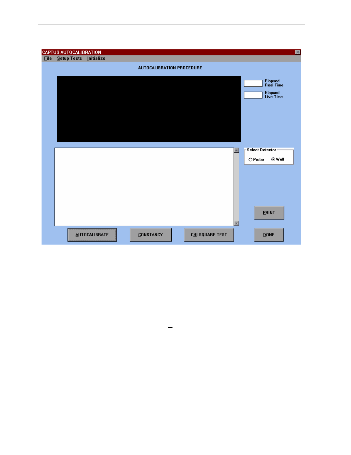
CAPINTEC, INC CAPTUS
®
2000
Figure 5-1
Energy Calibration
The first step in the Autocalibrate Sequence is measurement of the Cs137 standard. This
function uses the 662 keV peak and the 32 keV peak of Cs137 to automatically adjust the
high voltage, coarse gain, fine gain, and zero offset to provide a calibration of approximately
2.0 keV per channel in the MCA.
To start the autocalibration process, click the A
UTOCALIBRATE button with the track ball or
press (Alt-A). A pop up screen will prompt the user to place the Cs137 standard in position
as shown in Figure 5-2.
5-2 QUALITY ASSURANCE July 00
Page 55
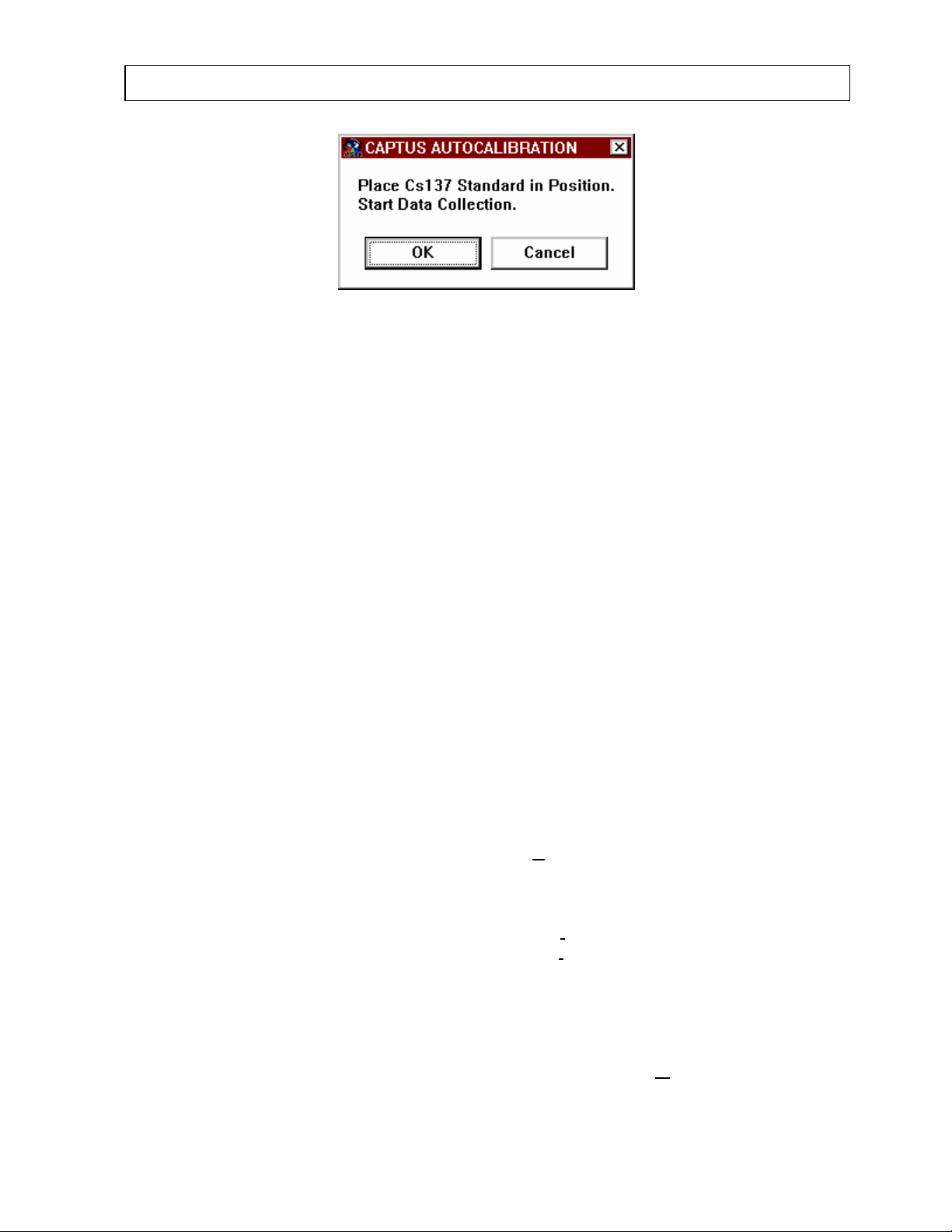
®
CAPINTEC, INC CAPTUS
2000
Figure 5-2
Place the Cs137 rod source in the well of a drilled well detector, or against the surface of the
flat field detector. For an easy way to insure reproducible source placement for the uptake
probe, turn the uptake probe so that the collimator opening is facing up towards the ceiling.
Gently place the black, flat plastic end of the source onto the middle surface of the crystal.
The rod source should stand freely and not lean to the side. To insure that the rod is
consistently placed in the center of the probe face, you may want to fashion a piece of
cardboard into a circle with a hole in its center to put the rod through. (Styrofoam or paper
cups work well.) The cardboard or cup will brace against the inside cylindrical wall of the
collimator to keep the rod source in position. This positioning will provide acceptable count
rates for quick calibration of the flat field detector.
NOTE: Never put a sharp instrument like a pen into the well or collimator. If the aluminum
coating of the NaI detector is scratched, allowing light and moisture to penetrate, the detector
will be ruined. The rod source is plastic and can be safely placed against the surface of the
detectors when handled carefully.
After the source is in place, select OK to proceed with the calibration process. Choose
CANCEL if you do not wish to proceed with the Cs137 calibration. The system will count,
evaluate the results of the measurement, adjust the calibration parameters, and remeasure.
The system will repeat this procedure until the 32 keV peak of Cs137 appears in channel 16
± 1 channel, and the 662 keV peak of Cs137 appears in channel 331 ± 2 channels. The
software will automatically count for as long as necessary until sufficient counts are acquired
for proper calibration. The voltage, gain settings, and zero adjust values will appear in the
display area. These calibration parameters are automatically saved after each test to a
calibration file. To stop the counting process, select A
BORT during acquisition. This will
return you to the main autocalibration screen. When the process is complete "DONE"
appears in the MCA display area.
If the error message, "Unable to Adjust" appears, select I
the top of the main autocalibration screen. Select Auto I
nitialize from the Menu Bar across
nitialize from the drop down list that
appears. This will reset the High Voltage to 1000 Volts, and the coarse and fine gain to
starting points to assure that the system will be able to adjust itself independent of detector
gain. A screen will appear and ask you to confirm the initialization process. Select OK to
proceed and reset the voltage to 1000, and CANCEL to return to the main autocalibration
screen. After initializing, proceed with the Cs137 autocalibration procedure as described
above. There is also an option on the drop down list to Initialize via M
CA. This allows the
program to use initial settings saved in the MCA part of the software. This option should be
used if the auto initialize feature does not work.
July 00 QUALITY ASSURANCE 5-3
Page 56
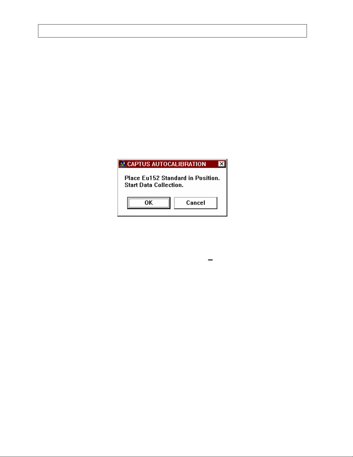
®
CAPINTEC, INC CAPTUS
2000
Note that during the autocalibration procedure with Cesium 137, a parameter labeled
“strength” appears in the results display area. The ratio of the strength values is used to
confirm that both Cesium 137 peaks are within the MCA viewing area for proper calibration.
If the sensitivity of a detector is great enough that the 662 keV peak is beyond channel 1024,
an error message stating, “Peak strength ratio is outside of expected range.” will appear.
Manually decrease the voltage setting through the MCA to about 800, save the settings
(Please note that you must save settings), initialize via MCA, and then repeat the
autocalibration procedure. This unlikely event should only occur when replacing a detector
or converting an older TUS-1000 system to a CAPTUS
®
2000 system.
The second step in the Autocalibrate sequence is the measurement of the Eu152 standard.
After the Cs137 measurement is complete, Figure 5-3 will appear.
Figure 5-3
After the source is in place, select OK to proceed with the calibration process. At any time
while counting, acquisition can be stopped by selecting the A
multiple gammas over an energy range of 41 keV to 1,408 keV. The CAPTUS
BORT button. Eu152 provides
®
2000
software provides a point by point energy calibration using these gammas. This function
corrects for any nonlinearity in response of the NaI detector and provides accurate
identification of the energy of photopeaks. It is important to complete the calibration of your
system using Eu152. The ROI’s in the Thyroid Uptake and Lab Tests are based upon the
energy ranges defined by the Eu152 calibration. In addition, the automatic peak
identification program which is accessed in the Wipe Test and MCA requires the Eu152
energy calibration in order to work properly. The system will automatically count until 10,000
peak counts are acquired. When the process is complete, “DONE” appears in the MCA
display area. The software will incorporate both the Cs137 and Eu152 peaks into the energy
calibration, and a listing of energy and channels will appear in the data display area. You
can omit the Eu152 energy calibration by selecting the Cancel button shown in Figure 5-3.
However the user will be warned that omitting this step may cause inconsistencies in the ROI
used in the clinical programs and the automatic peak finding program. Figure 5-4 will
appear.
5-4 QUALITY ASSURANCE July 00
Page 57
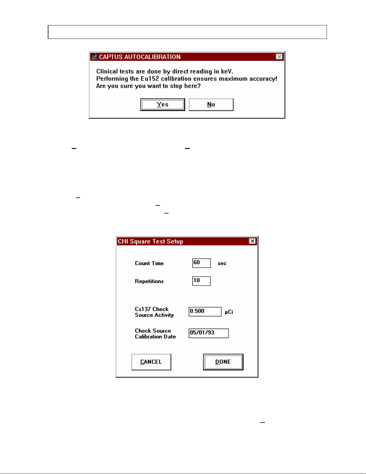
®
CAPINTEC, INC CAPTUS
2000
Figure 5-4
Select Y
es to omit the Eu152 calibration, and No to return to Figure 5-3.
Constancy
The third step in the daily test and calibration process is a Constancy Test. Before
performing the Constancy Test, the standard source calibration information must be entered
through S
enter calibration information, select S
main Autocalibrate screen. Select the S
etup Tests and the efficiency must be entered through the Isotope Library. To
etup Tests from the menu bar located at the top of the
etup Tests listing that appears in the drop down list
so that a CHI Square Test Setup window shown in Figure 5-5 appears.
Figure 5-5
In the appropriate text entry boxes, type the activity and calibration date that correspond to
the Cesium 137 rod source that was provided with your system. Select D
July 00 QUALITY ASSURANCE 5-5
ONE to save the
Page 58
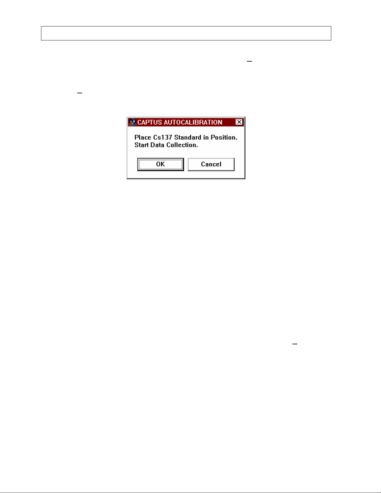
®
CAPINTEC, INC CAPTUS
2000
setup information and return to the main autocalibration screen, or CANCEL to exit without
saving and return to the main autocalibration screen. The Constancy Test uses this
calibration information to decay correct the Cs137 rod source.
Select the C
ONSTANCY button from the main Autocalibrate screen which is shown in Figure
5-1. Figure 5-6, will appear.
Figure 5-6
Select OK to begin the Cs137 measurement process, or Cancel to return to the main
autocalibration screen. Since the constancy test is a measure of reproducibility, it is very
important that the source be placed in exactly the same position each time the constancy test
is performed. Place the Cs137 rod source in the well of a drilled well detector with the black
tip down.
For an easy way to insure reproducible source placement for the uptake probe, turn the
uptake probe so that the collimator opening is facing upwards towards the ceiling. Gently
place the black, flat plastic end of the source onto the middle of the surface of the crystal.
NOTE: The source is plastic and can be safely placed against the surface of the detectors
when handled carefully. This placement will provide good positioning for reproducibility and
acceptable count rates for quick calibration of the flat field detector using the reference
source provided with the system.
Once the source is correctly placed, select OK to begin the Reproducibility Test, or CANCEL
to return to the main autocalibration screen. To stop the counting process, select A
BORT
during acquisition. You will return to the main autocalibration screen. When the process is
complete, "DONE" appears in the MCA display area. The system will count until at least
2000 vertical scale peak counts have been acquired. After completion of the constancy test,
the total count rate, live count time, calculated standard activity, measured activity, and
percent error will appear in the display area. The results of each constancy test is
automatically saved to a calibration file. The daily quality assurance tests should only take
about three minutes for each detector.
5-6 QUALITY ASSURANCE July 00
Page 59
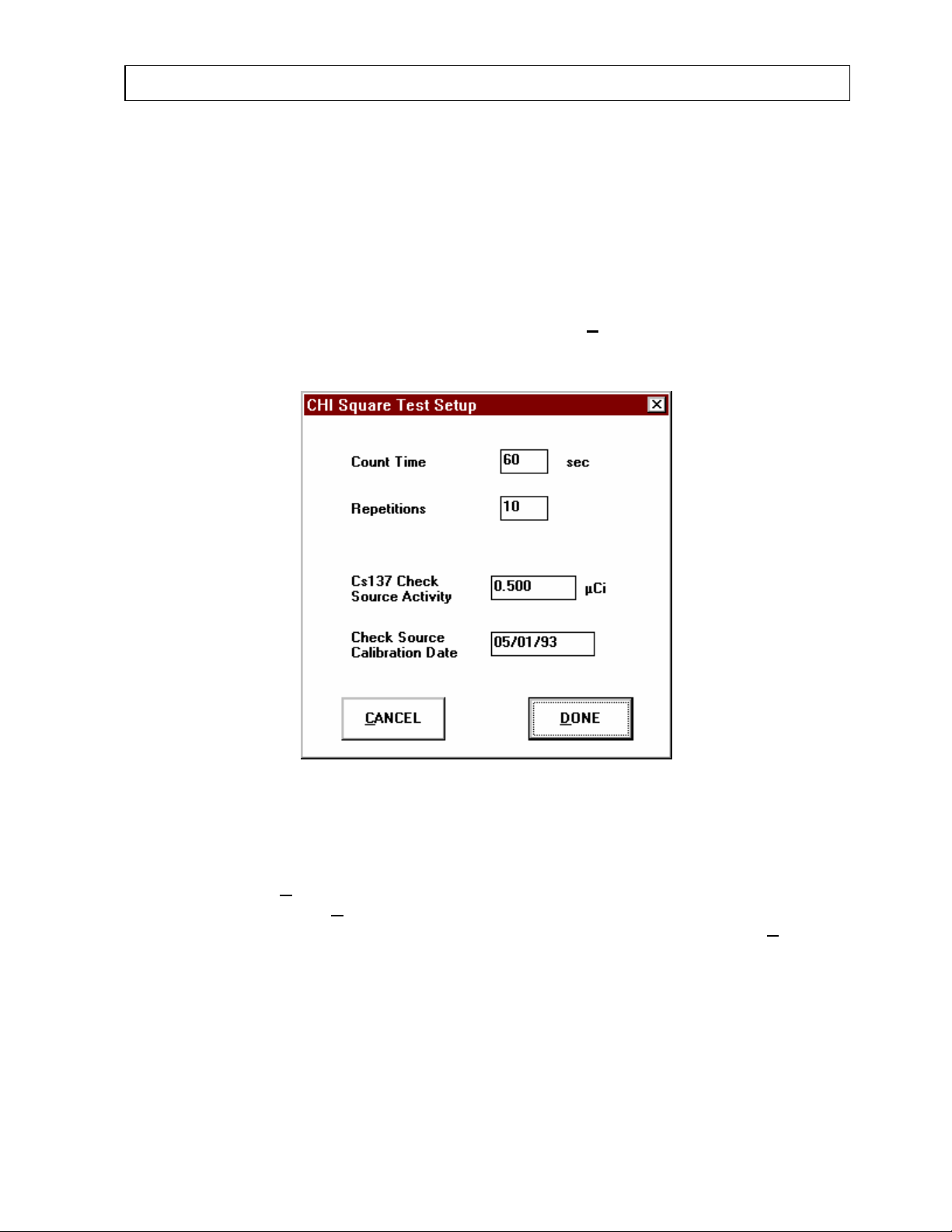
®
CAPINTEC, INC CAPTUS
2000
QUARTERLY TESTS
Chi-Squared Test
Upon acceptance testing and at least quarterly, a chi-squared and detector resolution test
should be performed. A chi-squared test is a very sensitive check of the overall counting
performance of the system. One of the counts during the measurement process will also be
used to automatically calculate detector resolution, which is a measure of the ability of a
system to distinguish between two peaks close in energy. The software will use the 662 keV
peak of your Cs137 source for both the tests. Before beginning the test, the number of
repetitions and counting time interval must be input. Select S
located at the top of the main autocalibration screen. Figure 5-7 will appear.
etup Tests from the Menu Bar
Figure 5-7
Enter the requested information. Note that the software also assumes that this Cesium 137
source is used for constancy testing. Default values are 60 seconds count time and 10
repetitions. Select D
autocalibration screen, or C
autocalibration screen. After setup information has been correctly entered, select CH
ONE to save the setup information and return to the main
ANCEL to exit without saving and return to the main
I
SQUARE TEST button. Figure 5-5 will appear. The source should be placed in the same
position as it is for the autocalibration and constancy tests. Once the source is correctly
placed, select OK to begin the reproducibility test, CANCEL to return to the main
autocalibration screen. The software will automatically proceed through the entire counting
sequence. Insure that the background rate does not change throughout the counting
process (i.e. no radioactive sources or dosed patients should pass by). Also insure that the
source is not moved until the test is completed. The collimator should not be bumped so that
the rod source is later found leaning against the inside of the collimator. It is recommended
that the chi-squared test be performed at the beginning or end of the day when the activity
July 00 QUALITY ASSURANCE 5-7
Page 60

®
CAPINTEC, INC CAPTUS
2000
(physical and radioactive) in the area around the CAPTUS® 2000 is unchanging. To stop the
counting process, select A
BORT at any time during acquisition. You will return to the main
autocalibration screen. When the process is complete "DONE" appears in the MCA display
area.
After the first count, the software will define a ROI which corresponds to the FWTM (full
width-tenth maximum) of the peak. This same region will be used to define the remaining
counts and appears in red in the spectrum display area.
Detector Resolution
The detector resolution is calculated by determining the FWHM (full width-half maximum)
area of the peak, and dividing by the peak centroid location. The standard deviation, or
sigma, for the peak used to calculate resolution is also listed. For peaks such as the 662
keV peak of Cs137 whose shape is symmetrical or appears to follow a Gaussian distribution,
the FWHM is generally close to 2.35 σ. Also during the chi-squared test, the software will
include a constancy test for convenience. Upon completion of the test, the chi-squared
value, % FWHM, sigma, and constancy test results will appear in the display area. It may be
necessary to use the scroll bar on the side of the text window to view all of the test results.
The results of each chi-squared test is automatically saved to a history file.
INTERPRETING THE TEST RESULTS
The autocalibrate results require little interpretation. Unless an error message is displayed,
the software will have succeeded in finding a set of adjustments which places the Cs137 32
keV X-ray peak within ± 1 channel and the Cs137 662 keV gamma peak to within ± 2
channels of the theoretical value for a calibration of 2.00 keV per channel. The software has
preset limits which prohibit operation outside of appropriate voltage, gain, and zero adjust
values.
The constancy test compares the Cs137 standard source activity that was entered into the
computer to the activity that was measured. The activity that was entered into the test setup
window (Figure 5-5) is decay corrected by the CAPTUS
actually measured in cpm which must be converted to units of activity by using the efficiency
stored in the isotope library. The deviation between the calculated and measured activity is
the percent error and should be within ± 5%. If the constancy test error is outside 5%, check
the positioning of the rod source, especially with the probe detector. Insure that there are no
other sources in the area, including dosed patients. (NaI detectors are very sensitive. Check
behind walls in adjacent rooms too.) Check the calibration date in the setup so that it
corresponds to your Cesium 137 rod source. Finally, you may have to remeasure the
efficiency of the Cs137 standard so that the measured activity is calculated correctly.
Efficiencies can be measured in the Isotope Library.
The chi-squared test requires more interpretation. Chi-squared values are given in the
following table for 5, 10, 15, and 20 samples. The chi-squared test results should fall
between the 0.95 and 0.05 probability values in the table almost all of the time. The more
stringent 0.90 and 0.10 values are given for reference. A chi-squared test result which is
much higher or much lower than expected should be repeated. Insure that there are no
®
2000 software. The activity is
5-8 QUALITY ASSURANCE July 00
Page 61

®
{
CAPINTEC, INC CAPTUS
2000
unexpected changes in background rate or temperature during the testing process. Make
sure that the source is securely positioned so that is does not move. If the Chi-squared
value is consistently out of range, it may indicate a problem with the counter/timer
mechanism of the system or the detector itself.
# Samples
0.95 0.90 0.10 0.05
5 .711 1.06 7.78 9.49
10 3.33 4.17 14.7 16.9
15 6.57 7.79 21.1 23.7
20 10.1 11.7 27.2 30.1
Using the table you can see that for a typical 10 repetition test, the chi-square value should
be between 3.33 and 16.9 for 95% of the time. Therefore, it is expected to be outside this
range 5% of the time. Also, because of the statistical nature of the chi-squared test, the chisquare values should not remain exactly the same. They are expected to vary.
The chi-squared test value is calculated from the following equation:
n
1
2
χ
=
i
=
av
nx
t measuremen for counts where
()
∑
x
av
=
i
1
ix
tsmeasuremen the for average
2
−=
xx
avi
This equation is the same as the following:
1
2
χ
()()()
1
x
av
2
2
1
...
2
}
xxxxxx
−++−+−=
1
avavav
Also reported on the chi-squared test is the detector resolution. For flat faced detectors the
resolution should be <
the resolution should be <
8.5 percent measured at the Cs137 662 keV peak. For well detectors
10 percent. Monitoring the stability of the resolution over time is
one of the best indications of the overall system performance. Detectors do age with use,
and this will result in a very slight increase (1% to 3%) in resolution over a period of several
years. A rapid increase in percent resolution may indicate a problem with the detector
assembly.
July 00 QUALITY ASSURANCE 5-9
Page 62
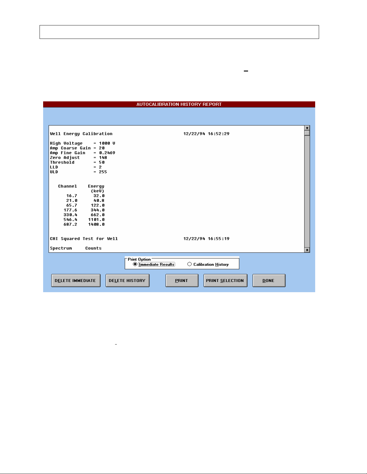
®
CAPINTEC, INC CAPTUS
2000
PRINTING TEST RESULTS
To print autocalibration and quality assurance test results, select the PRINT button from the
main autocalibration screen. The autocalibration history screen as seen in Figure 5-8 will
appear.
Figure 5-8
The software has three printing options. Immediate test results, complete history summary,
or a selected section of the displayed results. To print the most recent set of calibration and
test information, choose I
mmediate Results from the Print Option box. All of the raw count
data and calculated results will be displayed for the last calibration measurement. The
detailed data stored in immediate results must be printed as soon as the tests for a given
detector are complete. Performing an autocalibrate measurement causes the detailed
immediate result data to be erased. Then only the stored summary information is saved and
available for review. Figure 5-9 is a sample printout of immediate test results which list those
found during a normal daily calibration.
5-10 QUALITY ASSURANCE July 00
Page 63
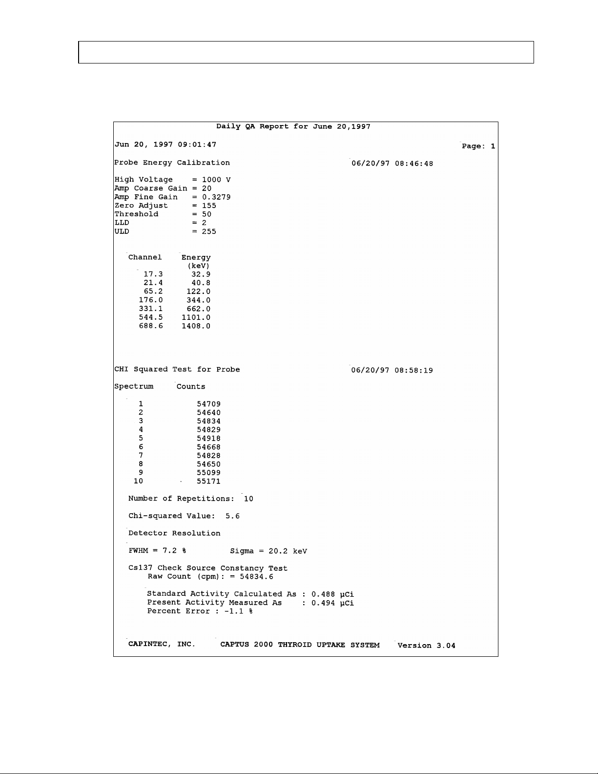
CAPINTEC, INC CAPTUS
Figure 5-9
®
2000
July 00 QUALITY ASSURANCE 5-11
Page 64
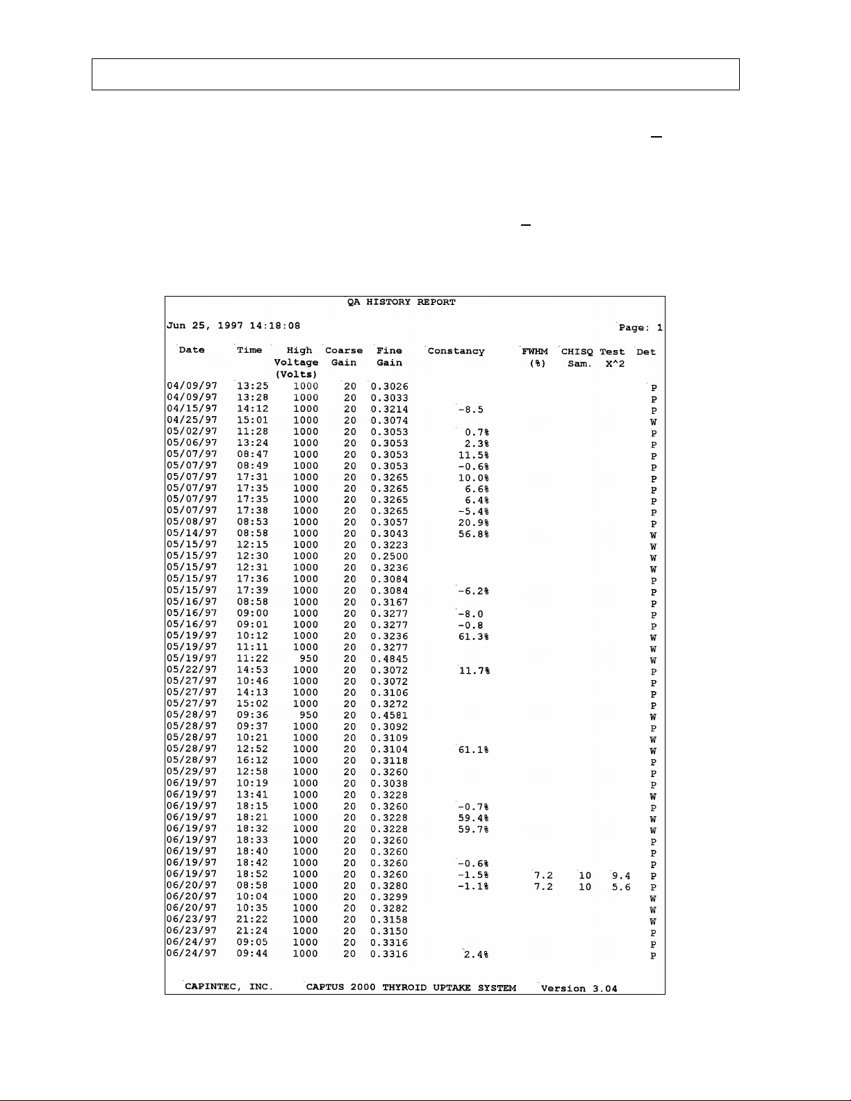
®
CAPINTEC, INC CAPTUS
2000
To print only the calibration history in a summary form, select the CALIBRATION HISTORY
from the Print Option box. The history reports a one line summary listing date/time, voltage,
gain, constancy, FWHM, and chi-squared results for each calibration. Use the scroll bar on
the side of the display area to view all of the results. The history report allows the user to
document and verify in a single document that the system is and has performed consistently
over time. After choosing the desired result format, select the P
RINT button to print the all of
the test data. Figure 5-10 indicates a typical calibration history report for a system over
several weeks of time.
Figure 5-10
5-12 QUALITY ASSURANCE July 00
Page 65

®
CAPINTEC, INC CAPTUS
2000
To print only a selected portion of the data, first place the trackball arrow indicator in the
display box. Click once and drag the arrow over the area to be printed. The data selected
will be highlighted. Once the data has been selected, choose the PRINT
S
ELECTION
button. Only the results which have been selected and are highlighted will print. The report
method is selected in the "Select Print Mode" frame check boxes just above the
P
RINT
button.
The system will continue to accumulate and save history information until 300 calibration
tests have been performed. Upon attempting to perform calibration test number 301, a
message window will appear and prompt you to print, archive and delete the history. Printing
and archiving are not mandatory, but you must delete the history to perform another
calibration test. Test results can be deleted in two ways, either by deleting the complete
history file, or deleting the immediate test results. To delete an immediate set of results,
select the D
calibration results. To delete the entire history, select the DEL
will delete all saved test data. The entire history can also be deleted by choosing the
function from the menu bar on the main autocalibration screen. After choosing
E
LETE IMMEDIATE button. This will delete only the most recent set of
ETE HISTORY button. This
F
ile
F
ile, Delete
History will appear. This will erase all history information stored in the system. After
selecting any of the delete commands, a pop up screen will appear and require the user to
confirm the delete procedure by asking “Are you sure you want to delete these results?”
Choose OK to confirm and delete, choose CANCEL to return to the previous screen without
deleting. A recommended procedure is to print out the history report and perform an archive
procedure at the end of each month for permanent record keeping. The history file can then
be deleted and a new file accumulated for the next month.
July 00 QUALITY ASSURANCE 5-13
Page 66

Page 67

CAPINTEC, INC CAPTUS® 2000
CHAPTER 6
THYROID UPTAKE
GENERAL INFORMATION
Thyroid uptake is a measurement of the ratio of the amount of radioactive material
concentrated in the thyroid gland to the amount of radioactive material administered to the
patient. Thyroid uptake measurements are generally used to determine conditions of
hyperthyroidism. High uptake results are found in Graves disease, toxic nodular goiter, TSHinduced, or with stimulator secreting tumors. Low uptake results are found with thyroid
hormone secretion in ectopic tumors, hormonal release in thyroid injury, after intake of
thyroid hormone, or Jod-Basedow disease. During the treatment of thyroid cancer by I-131
oblation, uptake measurements are used to monitor thyroid activity.
The CAPTUS
data for both the administered dosage and the patient, decay correct all count data, calculate
thyroid uptake results, and store all of this information in the thyroid uptake library. Regions
of Interest have been defined for three isotopes, I-131, I-123, or Tc99m. If normal values
have been entered, then results exceeding these values will be flagged. All of the patient
information may be printed. The thyroid uptake software has been designed to
accommodate a variety of different counting protocols, using either capsules or liquid
dosages. In the following sections of the chapter, the word capsule will be used for either a
capsule or liquid dosage.
NOTE: Before beginning any measurements in the Thyroid Uptake module, follow the
System Setup Procedures outlined in CHAPTER 4: SYSTEM SETUP, and the Quality
Assurance Procedures outlined in CHAPTER 5: QUALITY ASSURANCE to insure correct
operation of the CAPTUS® 2000.
To access the thyroid uptake software module, select T
CAPTUS
Figure 6-1.
®
2000 system will store patient demographic and dosage information, count
®
2000 screen, and the main THYROID UPTAKE screen will appear as shown in
HYROID UPTAKE from the main
July 00 THYROID UPTAKE 6-1
Page 68
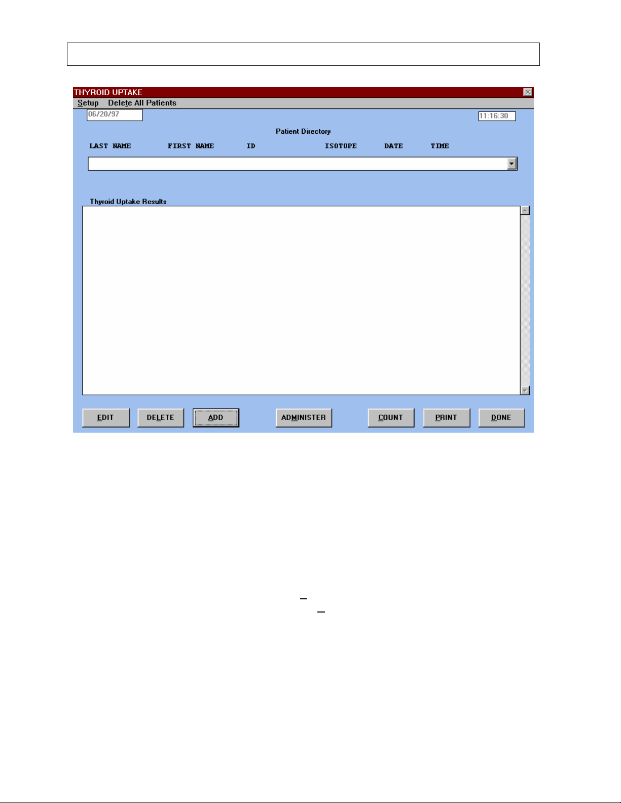
CAPINTEC, INC CAPTUS® 2000
Figure 6-1
All thyroid uptake features are accessed from the main THYROID UPTAKE screen. Before
beginning an uptake measurement, at least one measurement protocol must be added to the
list of protocols. Also, the isotope regions of interest, counting time, and probe distance
defaults should be defined.
DEFINING A MEASUREMENT PROTOCOL
To define a measurement protocol, select the Setup command, which is located on the
menu bar at the top left of the screen. Select the P
down list. A Protocols window will appear as in Figure 6-2.
rotocols listing that appears in the drop
6-2 THYROID UPTAKE July 00
Page 69
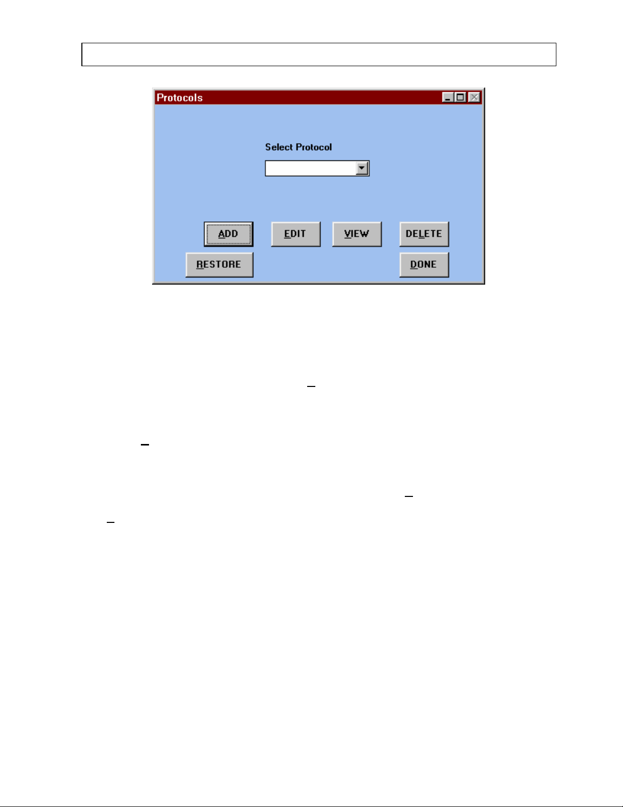
CAPINTEC, INC CAPTUS® 2000
Figure 6-2
The Protocols window contains a drop down list which contains all protocols entered into the
database. From this window, you can add new protocols, view, edit, or delete existing
protocols, and restore deleted protocols. To exit from the Protocols window and return to the
main THYROID UPTAKE screen, select the D
Adding Protocols
ONE command button.
Select the A
DD command button to add a new protocol to the list (which originally contains
no protocols). A PROTOCOL window with a series of option boxes will appear as in Figure
6-3. In each of the option frames, only one of the choice boxes to the left of each option may
be selected by using the radio buttons. In the text box, you must input the desired value.
After all of the protocol information has been defined, select the D
ONE button to save the
protocol and add it to the list of protocols. If you do not want to add a new protocol, select
the C
ANCEL button.
July 00 THYROID UPTAKE 6-3
Page 70
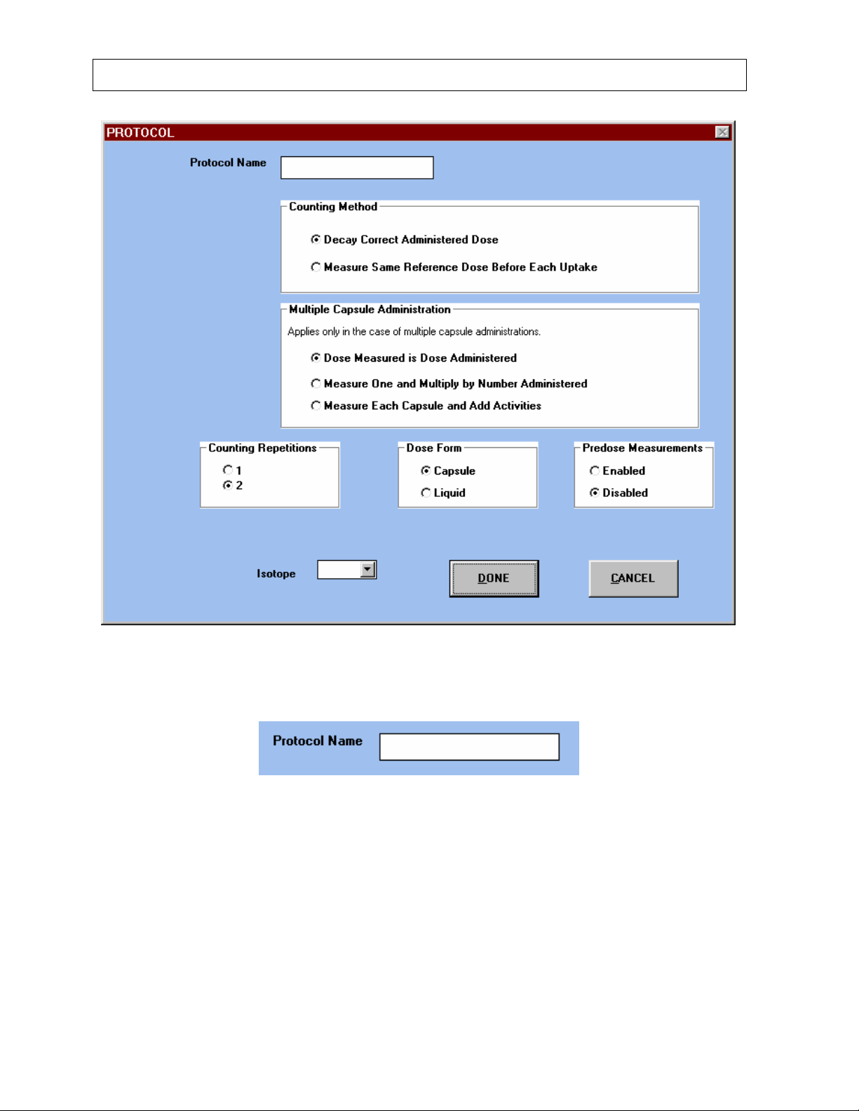
CAPINTEC, INC CAPTUS® 2000
Figure 6-3
Protocol Name
Figure 6-4
Select a name for the protocol by clicking on the white text box as it appears in Figure 6-4.
You may use up to 16 characters including spaces. No two protocols can have the same
name. If you give a protocol a name that is already being used, an error message window
will appear and tell you that the protocol name must be unique.
6-4 THYROID UPTAKE July 00
Page 71
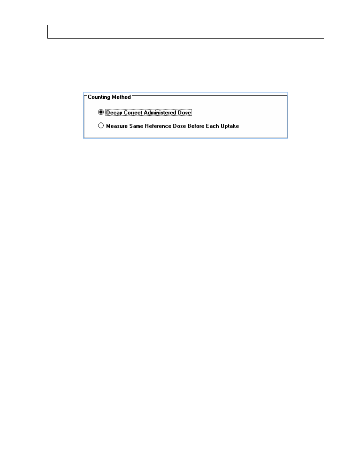
CAPINTEC, INC CAPTUS® 2000
Counting Method
First review the counting method box, Figure 6-5. Choose either Decay Correct
Administered Dose or Measure Same Reference Dose Before Each Uptake.
Figure 6-5
When Decay Correct Administered Dose is selected, the capsule must first be measured
before it is administered. Then this same capsule is administered to the patient.
The software will automatically correct the count rate for radioactive decay. Individual
capsules may vary in activity from each other. The decay correct method eliminates any
error introduced by a difference in activity from the capsule administered to the patient, and a
second different capsule used as a standard.
It is the easiest method, since it eliminates the need to recount a capsule each time an
uptake measurement is performed. This method is also the most cost effective since it
eliminates the cost of a second capsule used only as a standard. If your facility uses an
alternate method, try making comparison measurements with your current method and the
decay correct method. Most facilities find that the Decay Correct Administered Dose is the
most convenient method.
When Measure Same Reference Dose Before Each Uptake is chosen, the dosage may be
administered to the patient at any time. Before an uptake measurement is counted, the
software will prompt the user to measure the capsule first, then measure the patient. The
uptake will be calculated from each capsule count. If at any time, you choose not to remeasure the capsule for subsequent uptake measurements, the software will automatically
decay correct the most recent capsule count for the next uptake calculation.
July 00 THYROID UPTAKE 6-5
Page 72
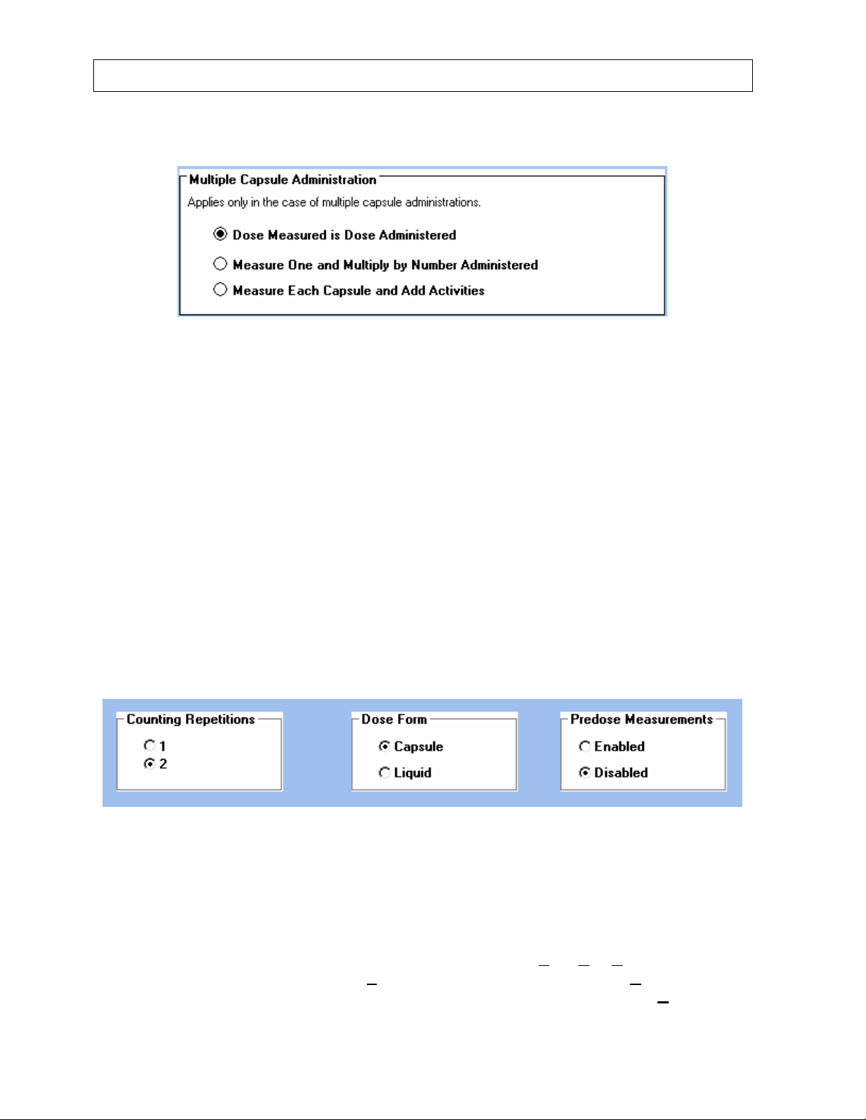
CAPINTEC, INC CAPTUS® 2000
Multiple Capsule Administration
Figure 6-6
When more than one capsule or dosage is given to any one patient, three methods of
measurement are available, as shown in Figure 6-6. When all capsules are counted at the
same time, choose Dose Measured is Dose Administered. By selecting Measure One and
Multiply by Numbered Administered, the software will count only one capsule, and then
multiply the count rate by the number or capsules administered to the patient. (Note: The
number of capsules administered is entered in the patient demographic screen when the
patient is added to the database.) The third option is to select Measure Each Capsule and
Add Activities. The software will prompt the user the count each of the capsules individually,
and add the activities together for a total capsule count. This total count is the count used for
thyroid uptake calculations.
Counting Repetitions, Dose Form, and Predose Measurements
Figure 6-7 shows additional parameters which must be defined as part of your counting
protocol including counting repetitions, dose form, and predose measurements.
Figure 6-7
Choose either 1 or 2 counting repetitions from the Counting Repetitions box. Each count
(capsule or patient) will be counted for the selected number of repetitions. The counts will be
averaged and the average count value will be used to calculate a thyroid uptake result. If
you choose 2 repetitions, you will be given the option to skip the second repetition after each
count. A screen will appear and ask, “Acquire Second Count? Y
proceed with the second count, select Y
es. To skip the second count select No. The
counting procedure will then proceed to the next step in the counting sequence. C
es. No. Cancel.” To
ancel will
6-6 THYROID UPTAKE July 00
Page 73
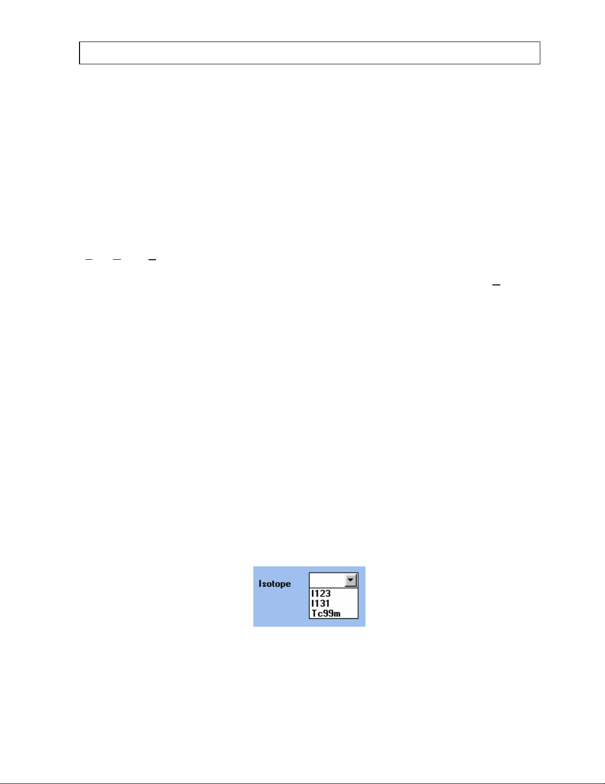
CAPINTEC, INC CAPTUS® 2000
return you to the previous screen without saving any count data. Note that when the room
background is measured after the capsule count, it is always only measured once.
Choose the correct type of dose, either capsule or liquid from the Dose Form box. Selecting
Capsule will result in the word capsule count on the results report. By selecting Liquid, the
term dosage will be substituted in any report for the word capsule. Choosing a dose form
only affects the wording of the results report, and has no effect on the measurement process
or calculations.
The Predose Measurements box can enable or disable the predose measurement option.
The predose option should be enabled whenever a patient has received radioactive material
before an uptake procedure is to be performed. When Enabled is selected, and the count
sequence initiated, a screen will appear and ask the user, “Perform Predose Measurement?
Y
es. No.” If Yes is selected, then a measurement of the patient’s thigh and neck should be
performed before any thyroid uptake radiopharmaceutical is administered. These predose
measurements will be subtracted from subsequent thyroid uptake measurements. If N
selected, then the Predose measurement will be omitted. If Disabled is selected from the
option box, then predose measurements will be omitted.
NOTE: The thyroid uptake predose measurement part of the CAPTUS
®
2000 software has a
peak finding algorithm that searches for the photopeak that corresponds to the particular
isotope (I-123, I-131, or Tc99m) that will be administered for the thyroid uptake as defined in
the protocol. If the peak is not found, a message will appear stating that no residual activity
was found. If a peak is found, the predose measurement records and subtracts the count
information from the same Region of Interest as the isotope that will be administered. The
predose measurement count rate will also be decay corrected using the same half life as the
isotope chosen for the thyroid uptake. Therefore, the predose measurement should only be
used when the previously administered isotope is the same isotope that will be used for the
thyroid uptake. For example, the predose measurement can be used for thyroid cancer
patients who have been treated with I-131 for tumor oblation, and then have a subsequent I131 thyroid uptake performed to evaluate the efficacy of the treatment.
Isotope
o is
Select the isotope to be administered from the isotope drop down box as appears in Figure
6-8. The choices are I-123, I-131, or Tc99m.
Figure 6-8
July 00 THYROID UPTAKE 6-7
Page 74
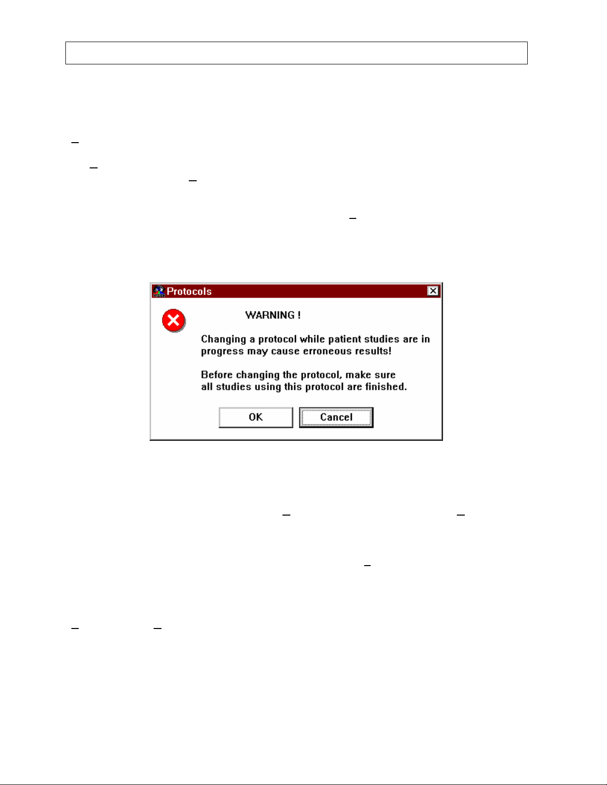
CAPINTEC, INC CAPTUS® 2000
VIEWING, EDITING, DELETING, AND RESTORING PROTOCOLS
Once a list of protocols has been created, you can view each protocol. From the Protocols
window as seen in Figure 6-2, select the protocol from the drop down list and then select the
V
IEW command button. A PROTOCOL window will appear as seen in Figure 6-3, but all
fields will be filled with the protocol’s information, the information will appear as inactive, and
the C
ANCEL button will not be shown. This is because this information cannot be edited,
only viewed. Select the D
In order to edit a protocol, go to the Protocols window as seen in Figure 6-2 and select the
desired protocol from the drop down list. Then select the E
protocol is being used in a patient study, a message window with a warning to finish all
studies that use the protocol will appear as seen in Figure 6-9. To exit, select the CANCEL
button. To edit the protocol, select the OK button.
ONE button to exit back to the Protocols window of Figure 6-2.
DIT command button. If the
Figure 6-9
A PROTOCOL window will appear as seen in Figure 6-3 will appear, but all fields will be
filled. Change the desired fields and select D
ONE to save the changes. Select CANCEL to
exit to the Protocols window without saving the changes.
In order to delete a protocol, go to the Protocols window as seen in Figure 6-2 and select the
desired protocol from the drop down list. Then select the DEL
ETE command button. If the
protocol is being used in a patient study, a message window with a warning to finish all
studies that use the protocol will appear that is similar to Figure 6-9. To exit, select the
CANCEL button. To delete the protocol, select the OK button. A window will appear with all
the protocol’s information and a Protocol Confirmation box as seen in Figure 6-10. Select
Y
ES to delete or NO to exit to the Protocols window without deleting.
6-8 THYROID UPTAKE July 00
Page 75
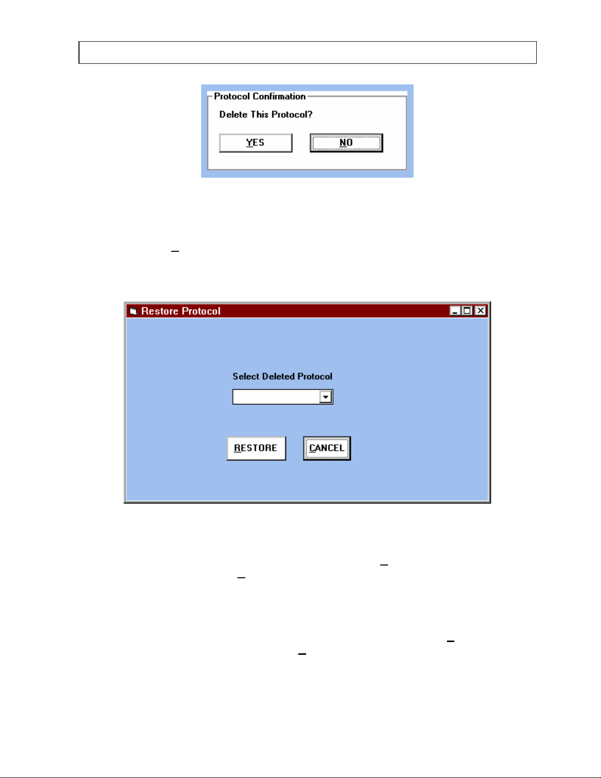
CAPINTEC, INC CAPTUS® 2000
Figure 6-10
Once a protocol has been deleted, it can be restored. From the Protocols window as seen in
Figure 6-2, select R
appear to tell you. If there are deleted protocols, a Restore Protocol window will appear as
seen in Figure 6-11.
ESTORE command button. If there are no deleted protocols, a message
Figure 6-11
Select the deleted protocol from the drop down list and select R
back to the protocol list. Select C
ANCEL to go back to the Protocols window.
ESTORE to add the protocol
REGIONS OF INTEREST
From the main THYROID UPTAKE screen as seen in Figure 6-1, select the Setup command
from the menu bar at the top left. Select the R
A TU ROI window will appear as seen in Figure 6-12.
July 00 THYROID UPTAKE 6-9
OI’s listing that appears in the drop down list.
Page 76
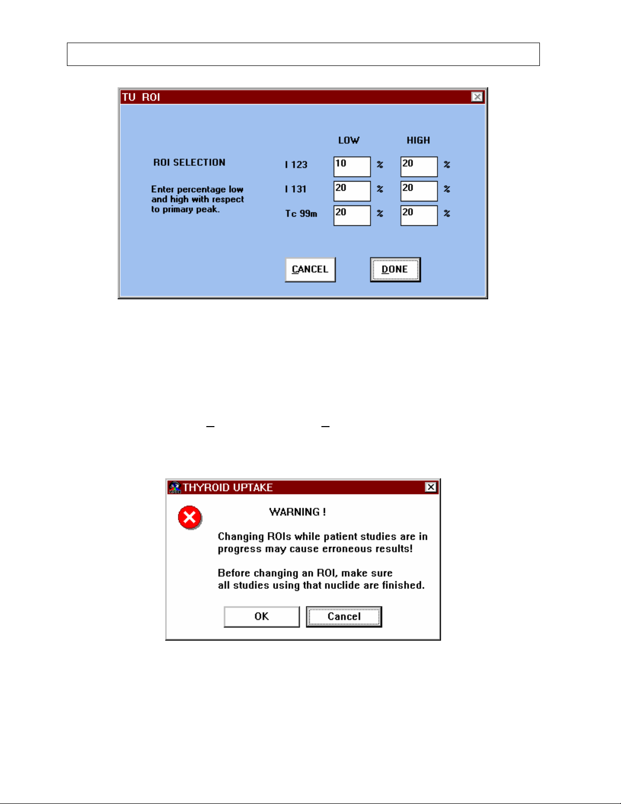
CAPINTEC, INC CAPTUS® 2000
Figure 6-12
Regions of Interest (ROI’s) are defined for the thyroid uptake isotopes based upon percent of
the primary peak. The ROI’s should be sufficiently wide so that the entire peak is within the
measurement window. Do not set ROI limits on the slope of a peak. The default settings
listed in Figure 6-12 provide an adequate window for good measurement results. The
CAPTUS
changing the ROI’s, select D
UPTAKE. If you try to change the ROI’s while there are active patients, a warning message
window will appear as seen in Figure 6-13.
®
2000 software automatically sets the ROI’s based upon the peak keV. After
ONE to save them or CANCEL to return to the main THYROID
Figure 6-13
6-10 THYROID UPTAKE July 00
Page 77
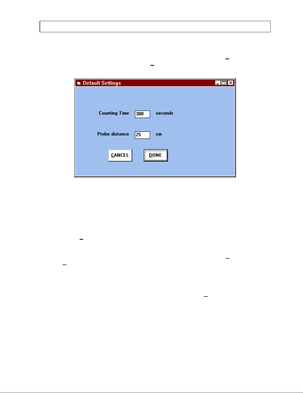
CAPINTEC, INC CAPTUS® 2000
COUNTING TIME AND PROBE DISTANCE
From the main THYROID UPTAKE screen as seen in Figure 6-1, select the Setup command
from the menu bar at the top left. Select the D
list. A Default Settings window will appear as seen in Figure 6-14.
efaults listing that appears in the drop down
Figure 6-14
Enter the desired counting time and probe distance as shown in Figure 6-14. Default
settings are 300 seconds and a probe distance of 25 cm. Changing them creates new
defaults. By selecting a probe distance between 24.5 cm and 35 cm, the field of view will
meet ANSI 44.3. The counting time should be set to provide at least 10,000 total counts.
Note that the entire counting time need not elapse for each measurement. During
acquisition, a ST
elapsed and save the count data. The counting time and probe distance will appear in each
patient demographic screen. These parameters may be changed for any patient as required.
After changing the probe distance and counting time default settings, select D
them or C
ANCEL to return to the main THYROID UPTAKE screen.
OP & SAVE button is available to stop the count before the preset time has
ONE to save
ADDING NEW PATIENTS
From the main THYROID UPTAKE screen, Figure 6-1, choose the ADD button. The Edit
Patient Library screen will appear as shown in Figure 6-15. Enter your patient demographic
data: patient name, ID, date of birth, and physician. Move from one data entry field to
another by using the Tab key, or placing the cursor in the appropriate field and clicking the
trackball. The date of birth, middle initial, and physician are optional fields and may be left
blank. The ID may be any combination of 16 alphanumeric characters.
July 00 THYROID UPTAKE 6-11
Page 78
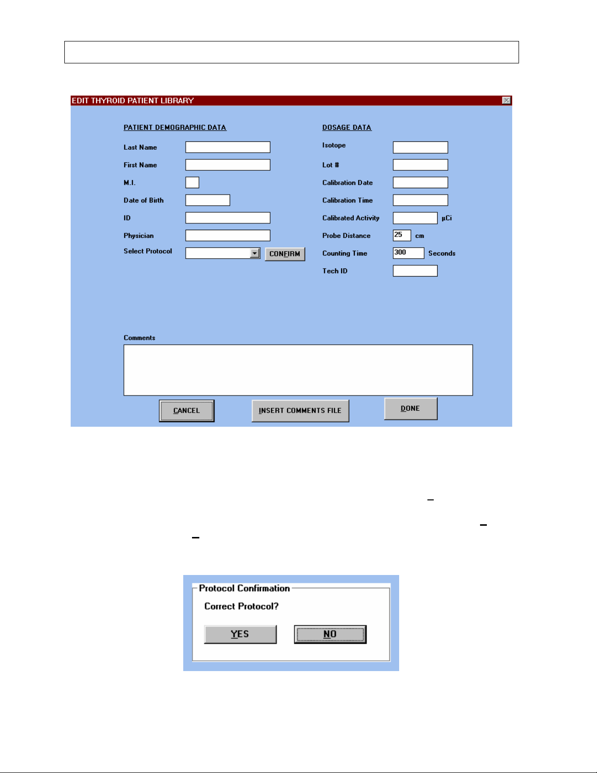
CAPINTEC, INC CAPTUS® 2000
Figure 6-15
If there is only one counting protocol, the name will appear. If more than one protocol exists,
select the desired protocol from the drop down list and then select the CONF
IRM command
button. A PROTOCOL window like the one seen in Figure 6-3 will appear with all the
protocol’s information and a Protocol Confirmation box as seen in Figure 6-16. Select Y
to confirm the protocol or N
O to exit to the EDIT THYROID PATIENT LIBRARY screen to
ES
select a new protocol. If the counting protocol that you wish to use does not appear, create
one and add it to protocol list as described above.
Figure 6-16
6-12 THYROID UPTAKE July 00
Page 79

CAPINTEC, INC CAPTUS® 2000
Next, enter your Dosage Data. The isotope associated with the selected protocol will appear
automatically. The counting time and probe distance will appear from the Default Settings
window, Figure 6-14. These default settings may be changed for any patient. Enter the lot
number, calibration date, time, and activity of the isotope.
The calibration date, time and activity should be entered from the time that the dosage was
measured in your dose calibrator. You can also use the calibration activity, date, and time
from the radiopharmacy. The CAPTUS
the calibration time to the time when the dosage was actually administered to the patient.
For this reason, it is important to enter the calibration date and time, and the administered
date and time correctly.
A comment section is available for free text input of up to 8,000 characters. A small amount
of information entered into the comment section will appear on the front sheet of the Thyroid
Uptake Measurement Report printout. A large amount of comment information will appear as
a second page addendum to the printed report. The I
enables the user to copy a previously stored .txt file. A .txt file is created by using Notepad
from the Windows
®
accessory screen. Select Notepad by clicking on the Notepad Icon.
Type in the desired text or create a form, and save. When using Notepad, it is best to save
the .txt file under the directory c:\sys2000\spectra because the CAPTUS
uses this default as the original directory when inserting a comment. Notepad automatically
saves files as .txt. This feature provides the user with the ability to create a standard
diagnosis report form and incorporate it into the thyroid uptake result report.
You may exit the Patient Data Screen at any time by selecting the D
information which has been entered will be saved to the thyroid patient library. To exit the
screen without saving any information, choose the C
A convenient testing method is to enter all of the demographic information concerning the
patients and the measured calibration activity as determined by your dose calibrator in the
patient library. Next, count each capsule for an initial capsule count to be stored in the
patient file. These tasks can be completed before any patients arrive at your facility. Then,
as each patient arrives, administer the capsule to the patient, and record the administered
time in the appropriate patient file. The CAPTUS
correct from the calibration time to the time when the dosage was actually administered to
the patient. This decreases the amount of time required while the patient is actually at the
department for thyroid uptakes.
®
2000 software will automatically decay correct from
NSERT COMMENTS FILE button
®
2000 software
ONE button. Any
ANCEL button.
®
2000 software will automatically decay
EDITING PATIENT INFORMATION
If you wish to review or edit any information which has already been entered on a patient,
first select the desired patient from the Patient Directory drop down box on the main
THYROID UPTAKE screen, then choose the E
display all of the data previously saved for the selected patient. Note that the ID appears as
inactive text (generally blue for Windows Version 3.1 and gray for Windows 95), and cannot
be changed. The reason for this is that the ID is used as an identifier by the software so
results are always stored in the correct file. If the ID has been entered incorrectly, you must
July 00 THYROID UPTAKE 6-13
DIT button. Figure 6-15 will appear and
Page 80

CAPINTEC, INC CAPTUS® 2000
delete the patient, and re-enter under the correct ID. After the desired changes have been
made, select the D
ONE button to save the changed information. CANCEL will exit the
screen without saving changes made to the patient library screen. Since each ID must be
unique to insure that results are always stored in the correct file, to save different uptake
studies on the same patient requires an ID extension. Using either A, B, C, or 1,2,3, is a
convenient way to tag the ID for each subsequent uptake study. For example, if a patient is
required to have an uptake performed every three months to monitor drug therapy, and you
wish to save all of the patient results concurrently, label the patient ID (for example 123456)
123456A for the first study, 123456B for the second study, 123456C for the third study and
so on.
NOTE: Before performing an acquisition or capsule administration, make sure that all
information in the EDIT THYROID PATIENT LIBRARY screen is correct. Once a capsule is
counted or administered, you will not be able to edit the protocol or dosage data. Only the
last name, first name, middle initial, and date of birth of the patient, the physician name, and
the counting time can be edited.
ADMINISTER DOSE
To record the date and time when the dose was administered to the patient, first select the
desired patient from the patient drop down list on the main THYROID UPTAKE screen,
Figure 6-1. Then select the ADM
INISTER button. Figure 6-17 will appear. (Note that if the
patient was assigned the Decay Correct Administered Dose counting method, and the
capsule was not yet counted, a message window will appear prompting you to count the
capsule before administering.) Input the date and time administered. By selecting the
A
DMINISTER NOW button, the current date and time will appear in the text boxes. The
CAPTUS
®
2000 will decay correct the activity automatically from the calibration time, and the
administered activity will appear in the patient demographic screen and on the results report.
6-14 THYROID UPTAKE July 00
Page 81
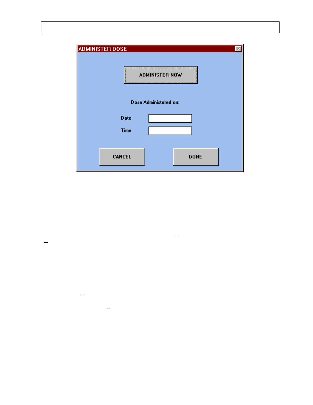
CAPINTEC, INC CAPTUS® 2000
Figure 6-17
Note that it is important to correctly enter the administered date and time when using the
decay correct method. In both the decay correct and the two capsule method, the software
will use the administered time to calculate the elapsed hours for the thyroid uptake
measurement. However, the administered time is not used to calculate actual uptake results.
Uptake calculations utilize the date and time when the capsule and neck counts are saved.
The time is taken from the computer clock. Choose C
D
ONE to save and exit the administered dose screen.
ANCEL to exit without saving, and
DELETING INFORMATION
The patients will remain in order of appearance in the Patient Directory drop down box until
deleted. To delete all of the information on a patient, first select the desired patient from the
Patient Directory drop down box on the main THYROID UPTAKE screen (Figure 6-1). Then
choose the DEL
18, and ask you to confirm that you really wish to delete this patient. Select OK to delete, or
CANCEL to undo the DEL
July 00 THYROID UPTAKE 6-15
ETE button. The software will present a pop up box as shown in Figure 6-
ETE command.
Page 82
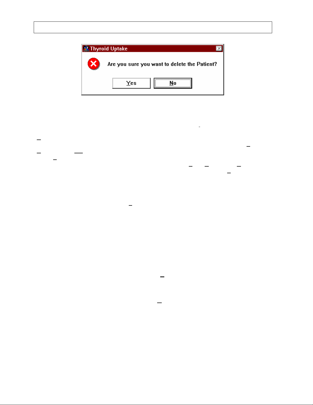
CAPINTEC, INC CAPTUS® 2000
Figure 6-18
To delete all patients and data in the patient library, select the Del
the menu bar located at the top of the main THYROID UPTAKE screen. Then select the
D
elete All listing that appears in the drop down list. A message window will appear asking,
“Are you sure you want to delete ALL the patient data for the Thyroid Uptake tests? Y
N
O.” Choose NO to cancel the delete command and return to the previous screen. If you
select Y
ES, another message will appear stating, “Deleting all test data CANNOT be undone.
Are you absolutely sure you want to delete all the test data? Y
cancel the delete and return to the main THYROID UPTAKE screen. Select Y
all patients in the library. The system will continue to accumulate patient data until 300
patients have been entered. Upon attempting to add patient number 301, a message will
appear prompting you to print out, archive, and delete all patients. Printing and archiving are
not mandatory, but you must delete the patients. You may either delete all the patients, or
delete individual patients with the DEL
ETE command button. A recommended procedure is
to periodically (monthly or quarterly) archive the patient data for reference, and then delete
all data from the thyroid uptake library. Alternatively, if you do not need to archive patient
results, at the end of each month print a hard copy report for each patient and then delete all
non-active patients.
ete All Patients listing from
ES.
ES. NO.” Select NO to
ES to delete
MAKING MEASUREMENTS
Once the test protocol has been defined and patient demographic information entered, you
can begin the counting process. Select a patient from the patient directory drop down list.
Begin the measurement process by choosing the C
UPTAKE screen, seen in Figure 6-1. The Thyroid Data Acquisition screen will appear as
shown in Figure 6-19. (If the patient is assigned a protocol that uses a standard reference
capsule, and you have not yet administered the capsule, a message will appear prompting
you to administer the capsule.) Note the Go To M
Thyroid Data Acquisition screen. This feature provides a direct link to the complete MCA
program without exiting from the thyroid uptake module. Use this feature to check the
isotope identification of a capsule, verify a region of interest, check a patient for previously
administered isotopes, or any other MCA use.
6-16 THYROID UPTAKE July 00
OUNT button from the main THYROID
CA command located at the top of the
Page 83
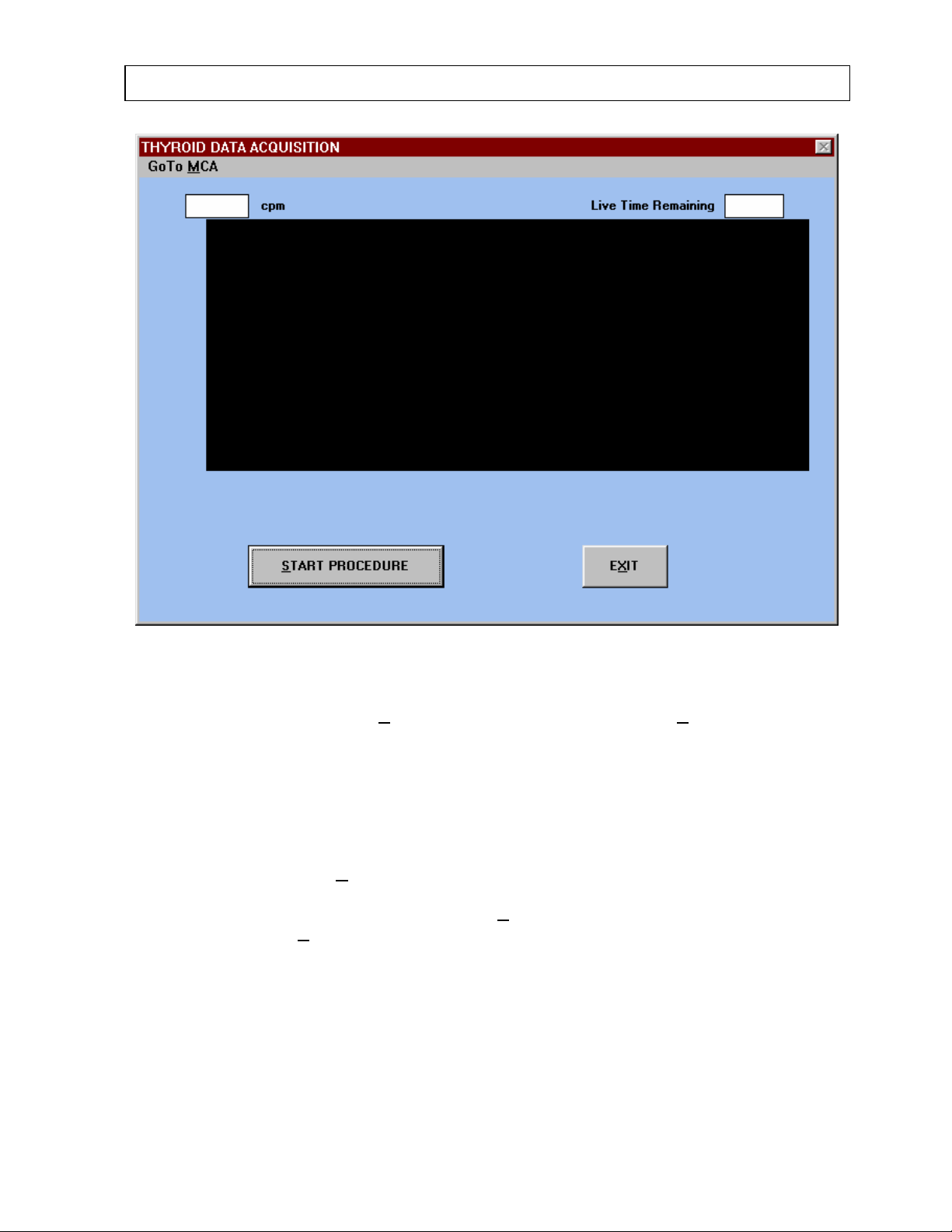
CAPINTEC, INC CAPTUS® 2000
Figure 6-19
To exit at any time choose the EX
IT button. To begin counting, choose START
PROCEDURE button. A sequence of pop up screens will appear as defined in your protocol
setup and prompt you through the correct measurement process. As the measurement
process begins and counts are acquired, the live spectra will be displayed on the screen.
The ROI selected will be highlighted in red to easily verify that it is correct. The live time
remaining will appear in the upper right hand corner of the screen. While counting, the
vertical scale counts will appear in the upper left corner of the screen. When finished
counting, the cpm measured in ROI will appear in the box at the upper left of the screen. To
abort the count, select the A
BORT ACQUISITION button, which appears during live
acquisition, and the count will not be saved. To stop the count and save the counting data
before the preset live time has elapsed, choose S
counting, select the EX
IT command. The display will return to the main THYROID UPTAKE
TOP & SAVE. When you are finished
screen. If two repetitions have been selected in the counting protocol, each of the
subsequent count screens will appear twice and two measurements for each count will be
recorded. The two counts will be averaged. Both the raw count data and the calculated
values will appear in the thyroid uptake result view box as shown in main THYROID UPTAKE
screen, Figure 6-1.
July 00 THYROID UPTAKE 6-17
Page 84
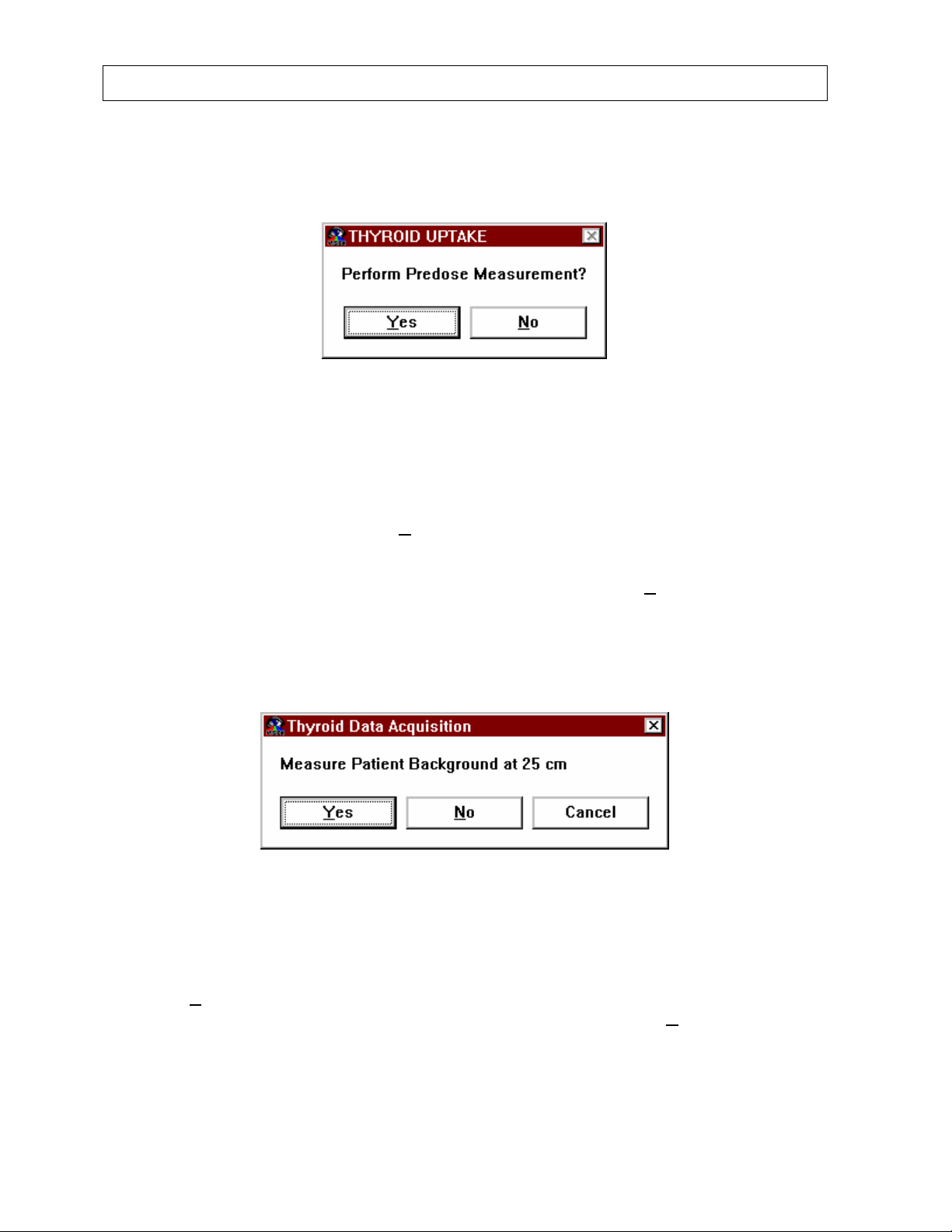
CAPINTEC, INC CAPTUS® 2000
Predose Measurements
If the protocol being used has predose measurements enabled, then Figure 6-20 will appear.
Figure 6-20
Predose measurements permit the measurement and correction for previously administered
residual isotopes in the patient. The predose measurement must be made before
administering the thyroid uptake radiopharmaceutical to the patient. The predose
measurement will be stored and subtracted from subsequent uptake measurements. To omit
the predose measurement, select the N
Then the software will proceed directly to Figure 6-25, and request a capsule count
measurement. To proceed with the predose measurement, select the Y
Figure 6-21 will appear. Note that the predose measurement only corrects for the same
isotope as that administered for thyroid uptake. If a peak is found, it counts the same ROI
and decay corrects using the same half life as the isotope selected for the thyroid uptake
procedure.
O button.
ES button, and
Figure 6-21
The patient background count is generally measured using the patient’s thigh as an estimate
for the neck. The patient background is used to correct for circulating labeled iodine or
Tc99m which is not concentrated in the thyroid gland. To measure the patient background,
select the Y
multiple repetition protocols, you may omit the second count by selecting N
ES button. You must make at least one patient background measurement. For
O. To exit from
the measurement process at any time without saving the measurement, select Cancel.
6-18 THYROID UPTAKE July 00
Page 85
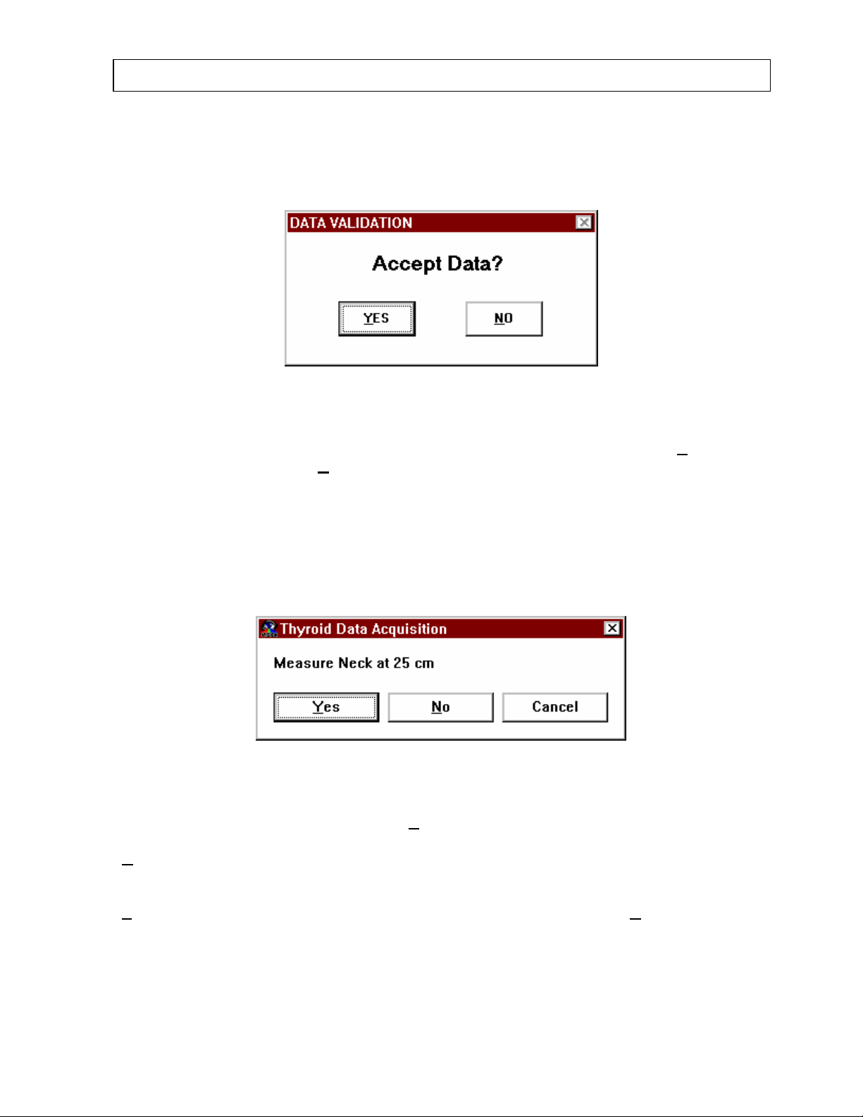
CAPINTEC, INC CAPTUS® 2000
After the measurement has been completed, you will be given the opportunity to reject the
count. Figure 6-22 will appear and require you to validate and accept the count data before it
is permanently saved to the patient result file.
Figure 6-22
This is an opportunity to reject an incorrect count. To accept the data, select the Y
To reject the data select the N
O button. You will then return to the previous step in the count
sequence, and have the opportunity to recount. Note that this data validation step is required
after any count in the thyroid counting sequence to confirm the count data before it is saved.
Once the data has been saved, it cannot be deleted from the patient result file.
After the predose patient background count has been completed, the next step is the
predose patient neck count. Figure 6-23 will appear.
ES button.
Figure 6-23
To measure the patient’s neck, select the Y
ES button. You must make at least one neck
measurement. For multiple repetition protocols, you may omit the second count by selecting
N
O. To exit from the measurement process at any time without saving the measurement,
select Cancel. After the measurement has been completed, you will be given the
opportunity to reject the count. Figure 6-22 will appear and ask for data verification. Select
Y
ES to accept the count and save the data to the patient result file, select NO to reject the
count data and return to the previous measurement in the counting sequence.
Once the predose measurements have been completed, the software will analyze the
predose data to verify that activity of the correct isotope has been detected. If no activity is
identified in the ROI which corresponds to the isotope chosen for thyroid uptake, then Figure
July 00 THYROID UPTAKE 6-19
Page 86
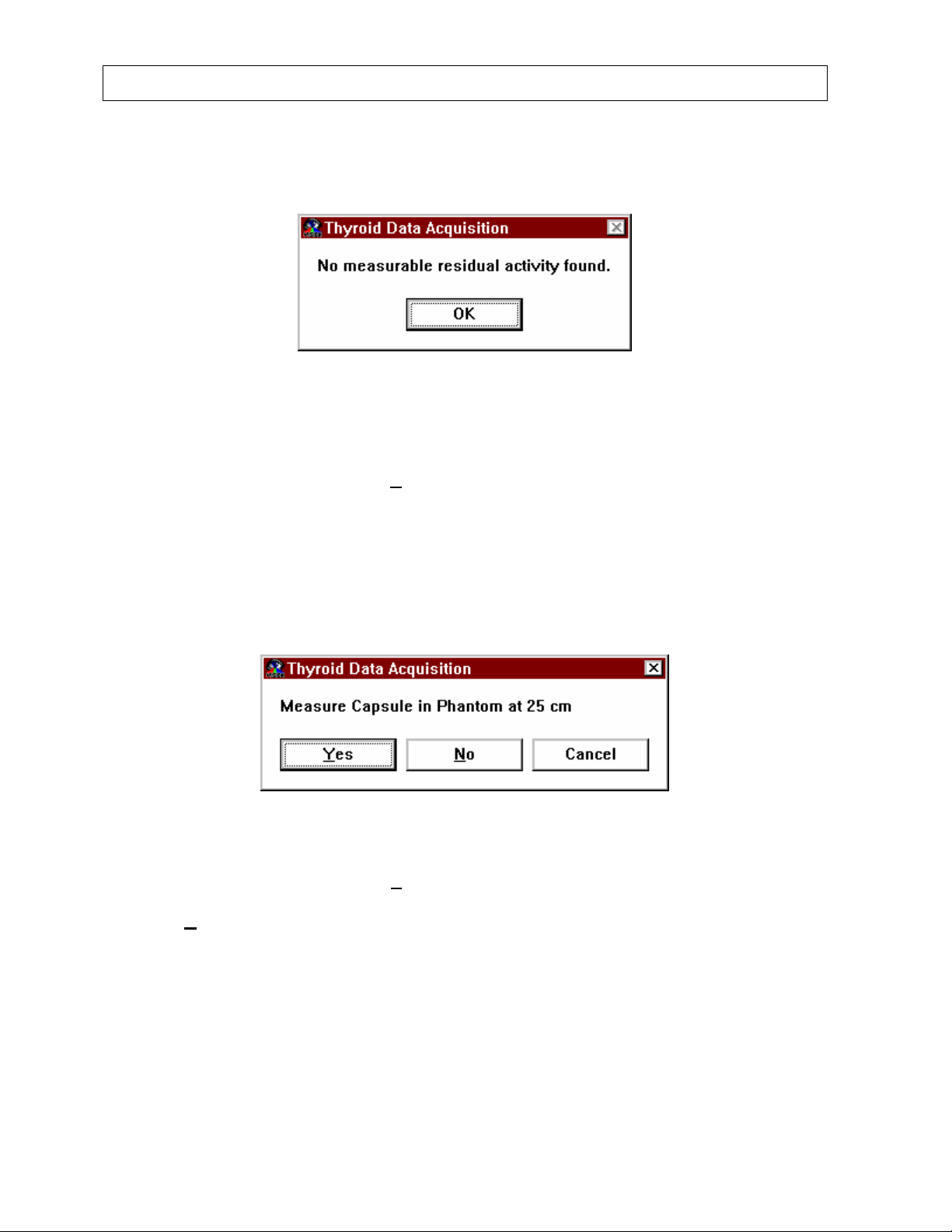
CAPINTEC, INC CAPTUS® 2000
6-24 will appear and no correction will be made for the residual activity. Select OK to confirm
receipt of the message.
Figure 6-24
The predose measurement results will appear in the thyroid uptake patient result area as
shown in the main THYROID UPTAKE screen, Figure 6-1. If the predose measurement is
disabled in the protocol selection, or N
Figure 6-20, then the predose measurement process will be omitted and the count sequence
will proceed directly to the capsule count measurement, Figure 6-25.
Capsule Count Measurement
O is selected from the Predose Measurement Screen,
The next step in the measurement process is a capsule count. Figure 6-25 will appear.
Figure 6-25
To make a capsule count, select the Y
es button. You must make at least one capsule
measurement. For multiple repetition protocols, you may omit the second capsule count by
selecting N
o. To exit from the measurement process at any time without saving the
measurement, select Cancel. After the capsule measurement has been completed, you will
be given the opportunity to reject the count. Figure 6-26 will appear and require you to
validate and accept the count data before it is permanently saved to the patient result file.
6-20 THYROID UPTAKE July 00
Page 87
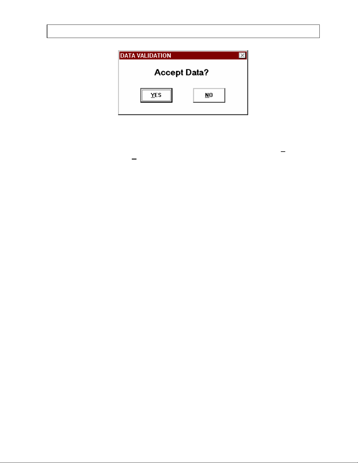
CAPINTEC, INC CAPTUS® 2000
Figure 6-26
This is an opportunity to reject an incorrect count. To accept the data, select the Y
To reject the data select the N
O button. You will then return to the previous step in the count
sequence. Note that this data validation step is required after any count in the thyroid
counting sequence to confirm the count data before it is saved. Once the data has been
saved, it cannot be deleted from the patient result file.
If you have selected “Measure Each Capsule and Add Activities” from the Multiple Capsule
Administration protocol, then the Figure 6-25 will appear again. It will be labeled, “Measure
Capsule # 2 in Phantom at 25 cm.” The screen will reappear as many times as the number
of capsules listed on the patient demographic data screen, until all of the capsules have been
counted. If two repetitions have been selected, each capsule will be counted twice. For
example, if three capsules are administered with two repetitions, then Figure 6-25 will appear
six times. The counts will be labeled appropriately. For example, Capsule # 1 First Count,
through Capsule # 3 Second Count. All of the raw count data and the calculated total count
will appear in the thyroid uptake results display box shown in Figure 6-1, the main THYROID
UPTAKE screen.
If Measure One and Multiply by Number Administered was selected from Multiple Capsule
Administration protocol, then Figure 6-25 will appear only once. The count data will be
multiplied by the number of capsules listed on the patient demographic data screen, and both
the raw count data and calculated total count will appear in the thyroid uptake results display
box shown in Figure 6-1, the main THYROID UPTAKE screen.
When using a decay correct protocol, you have the option of using the previous room
background and capsule counts (the previous net capsule counts). This option is only
available if the date of capsule measurement, protocol, lot number, calibration date, and
calibration activity, are exactly the same for the current patient and the previous patient. If
the above conditions are met, then upon beginning a capsule count, a message will appear
as shown in figure 6-27.
ES button.
July 00 THYROID UPTAKE 6-21
Page 88
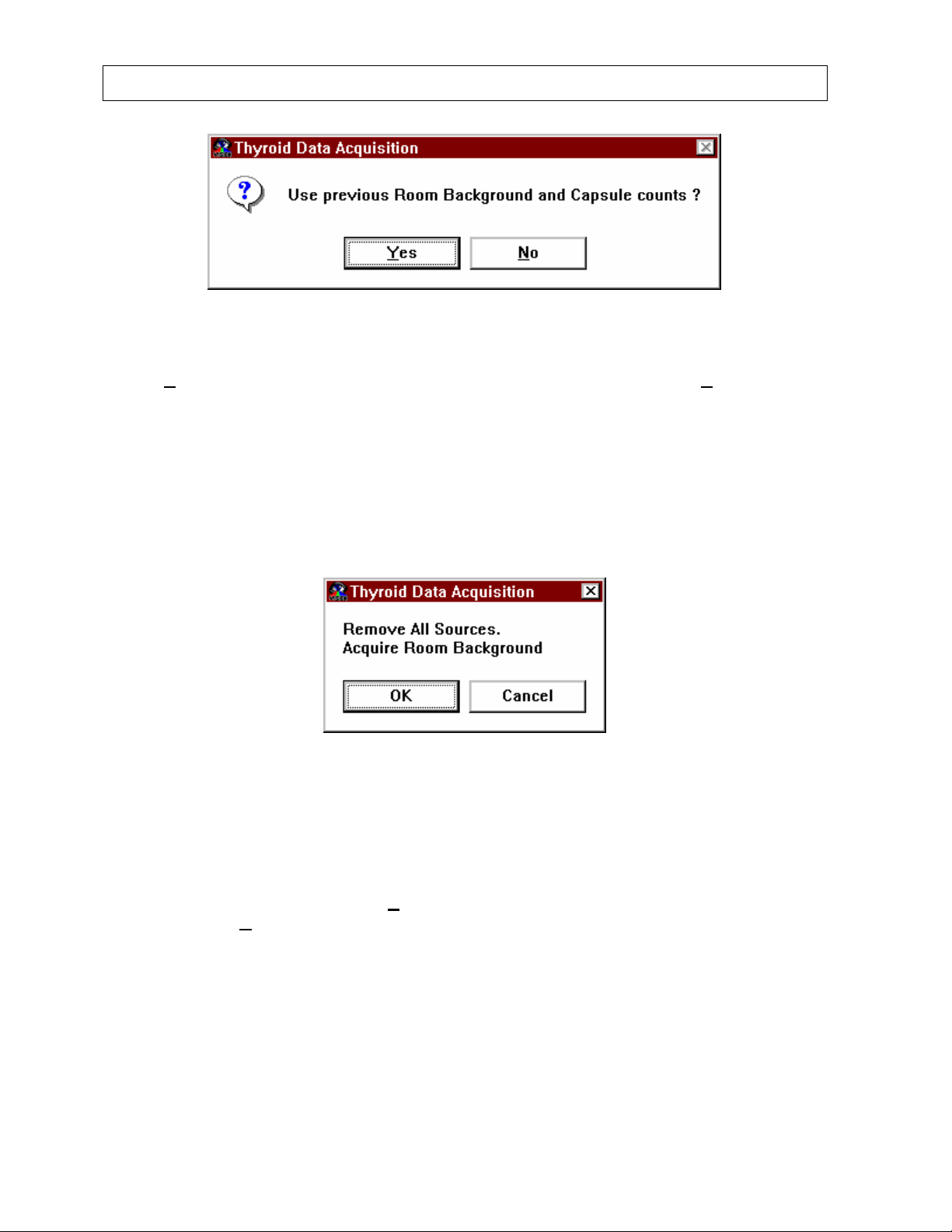
CAPINTEC, INC CAPTUS® 2000
Figure 6-27
Select Y
es to use the previous room background and capsule counts. Select No to count
the capsule. This option will save you from having to measure a capsule of the same activity
for several patients on the same day. These values are saved in memory and will not be
available to use in this way if you exit the CAPTUS
®
2000 program.
Room Background Measurement
The next step in the measurement process is the room background count.
Figure 6-28
To take a background measurement, select the OK button. You will only have to measure
the room background once. To exit from the measurement process at any time without
saving a background measurement, select Cancel. After the background measurement has
been completed, you will be given the opportunity to reject the count. Figure 6-26 will appear
and ask for data verification. Select Y
result file, select N
O to reject the count data and return to the previous measurement in the
ES to accept the count and save the data to the patient
counting sequence.
You have the option of repeating the room background measurements. After the first room
background count for a particular isotope, subsequent room background counts for that
isotope do not have to be made if on the same day. Upon beginning a room background
count, a window will appear like the one shown in Figure 6-29.
6-22 THYROID UPTAKE July 00
Page 89
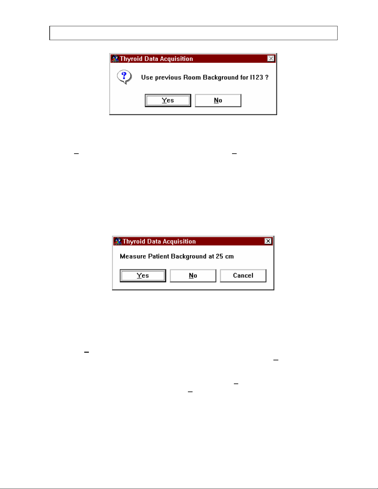
CAPINTEC, INC CAPTUS® 2000
Figure 6-29
Select Y
es to use the previous room background counts or No to count the room
background. Note that the window will display which isotope is being used. If the ROI is
changed for a particular isotope, the room background counts corresponding to that isotope
will also be affected.
Patient Background Count
Once a room background and capsule count have been measured and saved, the patient
may then be counted. Figure 6-30 will appear and request a patient background count.
Figure 6-30
The patient background count is generally measured using the patient’s thigh as an estimate
for the neck. The patient background is used to correct for circulating labeled iodine or
Tc99m which is not concentrated in the thyroid gland. To measure the patient background,
select the Y
multiple repetition protocols, you may omit the second count by selecting N
es button, you must make at least one patient background measurement. For
o. To exit from
the measurement process at any time without saving the measurement, select Cancel. After
the measurement has been completed, you will be given the opportunity to reject the count.
Figure 6-26 will appear and ask for data verification. Select Y
save the data to the patient result file, select N
O to reject the count data and return to the
ES to accept the count and
previous measurement in the counting sequence.
July 00 THYROID UPTAKE 6-23
Page 90
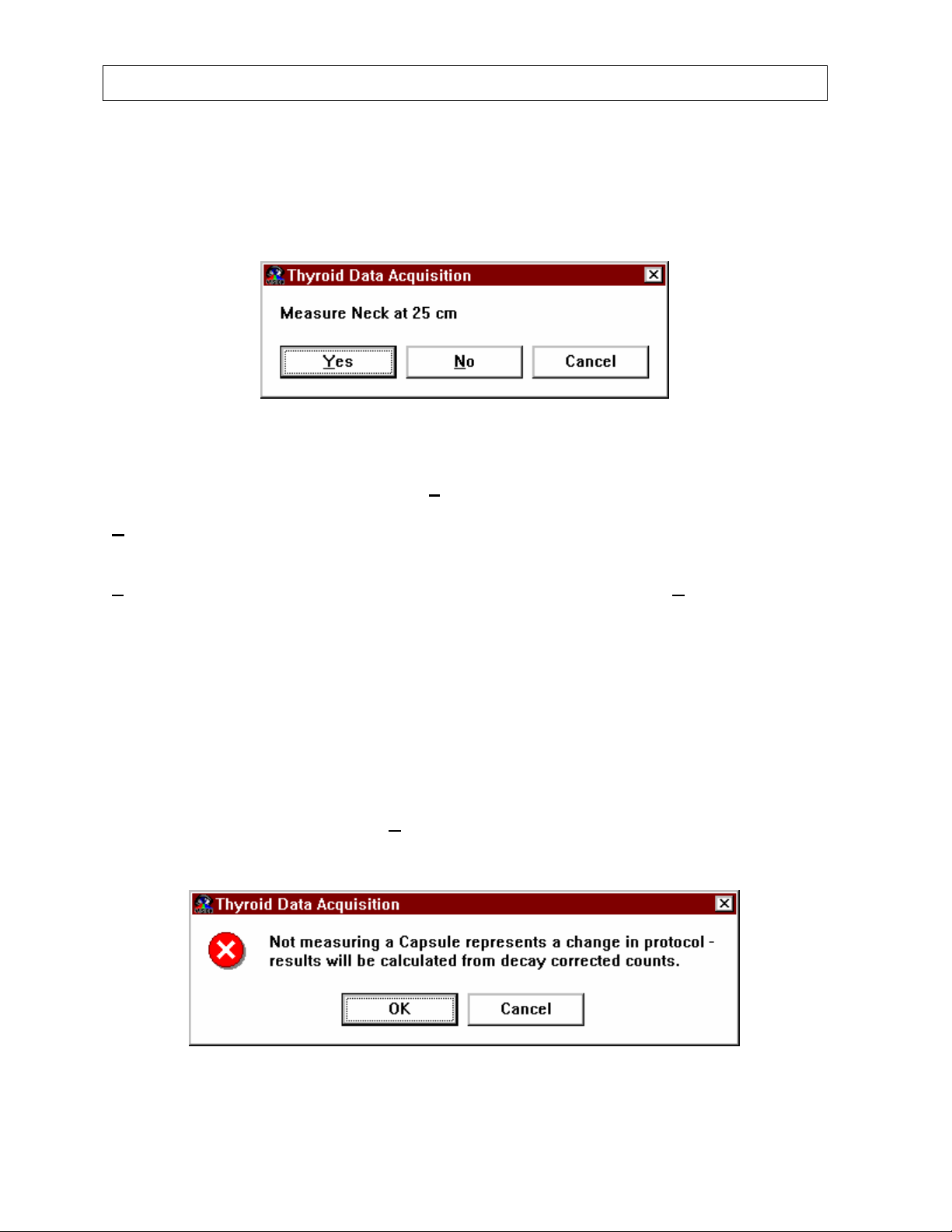
CAPINTEC, INC CAPTUS® 2000
Patient Neck Count
After the patient background is measured and saved, Figure 6-31 will appear and the
patient’s neck must be counted to determine the activity of isotope concentrated in the
thyroid gland.
Figure 6-31
To measure the patient’s neck, select the Y
measurement. For multiple repetition protocols, you may omit the second count by selecting
N
o. To exit from the measurement process at any time without saving the measurement,
select Cancel. After the measurement has been completed, you will be given the
opportunity to reject the count. Figure 6-26 will appear and ask for data verification. Select
Y
ES to accept the count and save the data to the patient result file, select NO to reject the
count data and return to the previous measurement in the counting sequence.
If Decay Correct Administered Dose was selected for the counting protocol, then subsequent
uptake counts on the same patient will automatically calculate the capsule count, and
proceed to Figure 6-30 and 6-31, patient background and neck counts.
If Measure Same Reference Dose Before Each Uptake was selected as the counting
protocol, then each subsequent uptake count of the same patient will require the entire
counting sequence from Figure 6-25 through Figure 6-31 to be repeated. The software does
allow the option to choose to decay correct subsequent counts rather than repeat the
capsule count. To decay correct subsequent capsule counts using Measure Same
Reference Dose protocol, select the N
Figure 6-32 will appear.
es button. You must make at least one neck
O button from the Capsule Count Screen, Figure 6-25.
Figure 6-32
6-24 THYROID UPTAKE July 00
Page 91
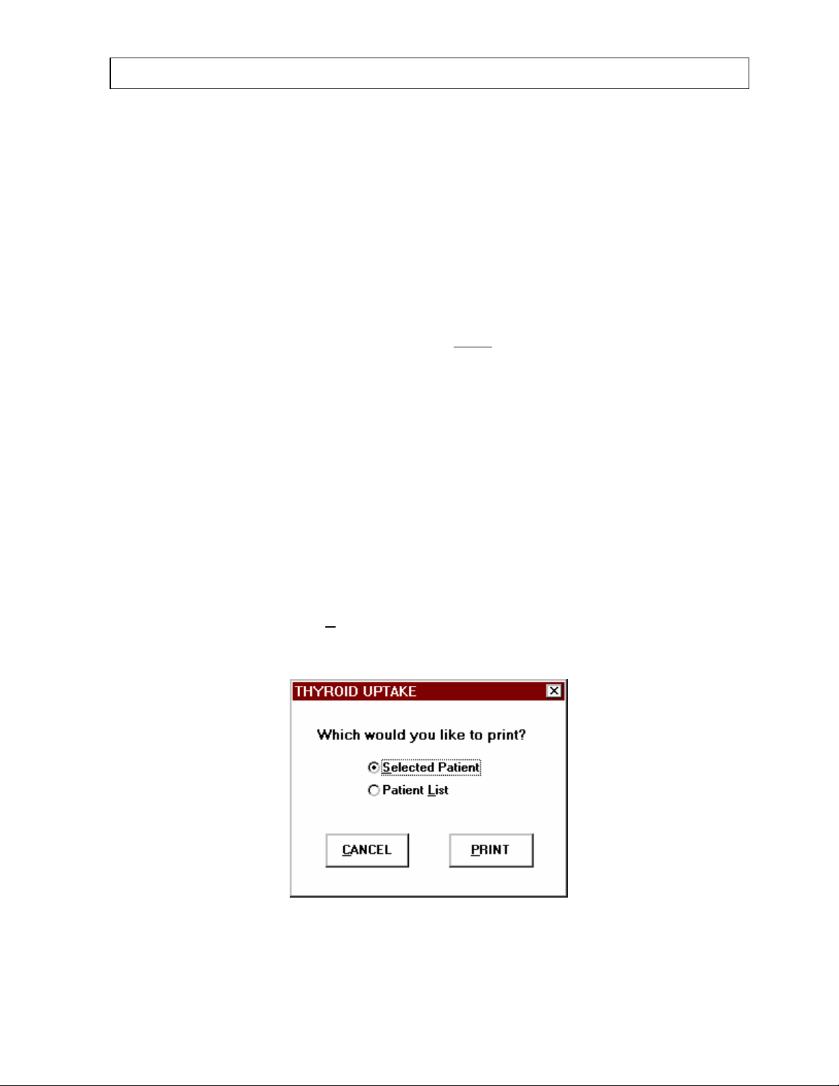
CAPINTEC, INC CAPTUS® 2000
(
To eliminate a subsequent capsule count and decay correct from the original capsule count,
select OK. Select Cancel to return to the Capsule Count window, Figure 6-25.
RESULTS
All of the count data and calculated results appear in the Thyroid Uptake Results box on the
main THYROID UPTAKE screen, Figure 6-1.
The results are calculated as follows:
)
T-P
Uptake Thyroid %
where P = Patient neck count rate
T = Patient background count rate (thigh count)
C = Capsule (standard) count rate
B = Room background count rate
When a predose measurement has been recorded, then
P= Patient neck count rate - predose neck count rate
T = Patient background count rate - predose patient background count rate
()
100×=
B-C
PRINTING RESULTS
To print patient data select the PRINT button from Figure 6-1, the main THYROID UPTAKE
screen. Figure 6-33 will appear.
Figure 6-33
July 00 THYROID UPTAKE 6-25
Page 92
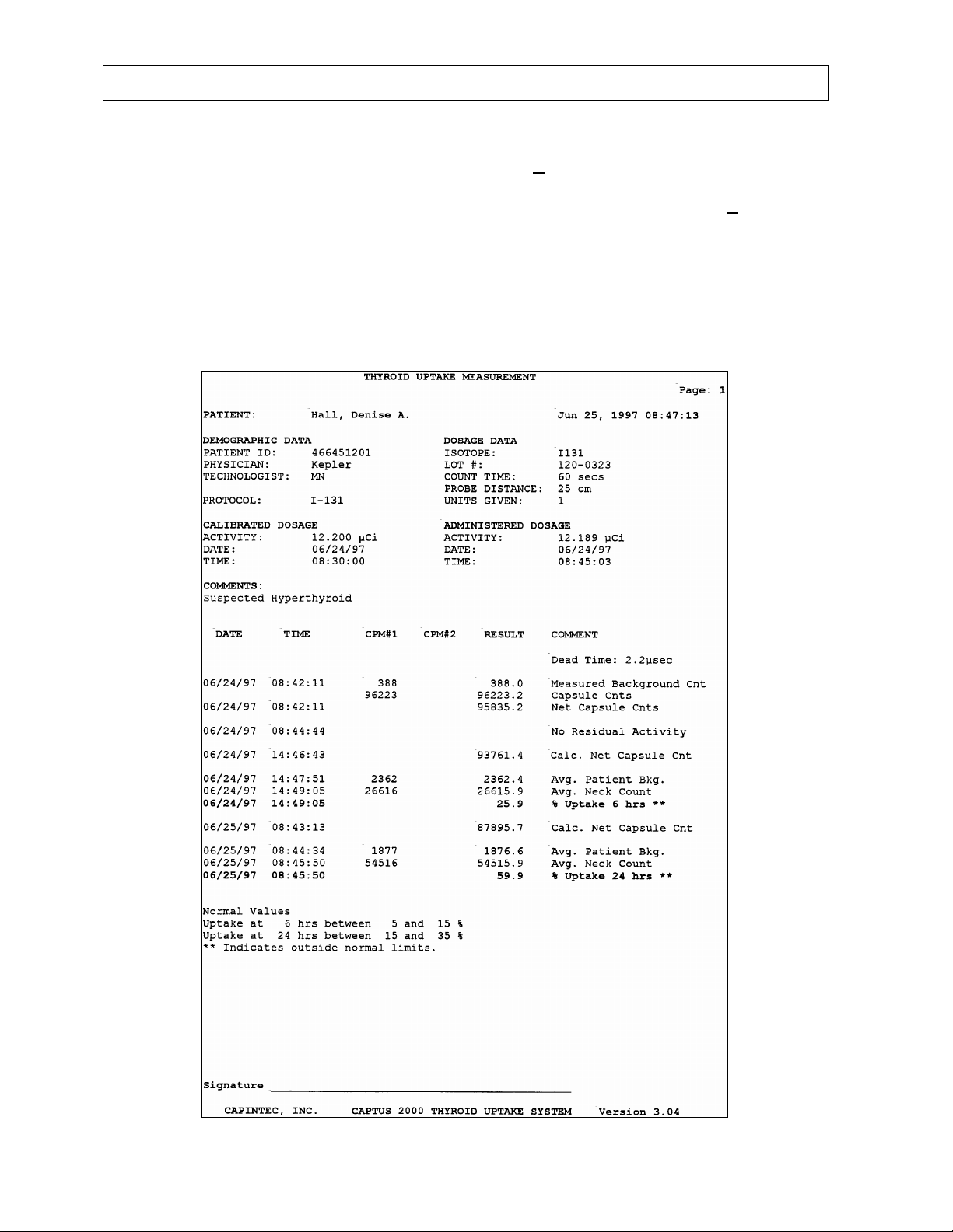
CAPINTEC, INC CAPTUS® 2000
To print a report which contains the patient demographic data, counting protocol, count data,
and calculated results for a specific patient, choose the S
amount of information that appeared as comments entered in the comment free text section
will appear as a second page addendum to the patient result report. Then select P
button to print the patient report. In addition, if normal ranges have been entered in the
Normal Value Setup module, then the normal ranges will be also be printed. Any results
outside of these limits, providing that the thyroid uptake was performed within 1 hour of the
stated time, will be flagged. Figure 6-34 demonstrates a typical thyroid uptake report for a
patient using the decay method protocol. Notice that the uptake outside of the listed normal
ranges is flagged.
Figure 6-34
elected Patient option. A large
RINT
6-26 THYROID UPTAKE July 00
Page 93
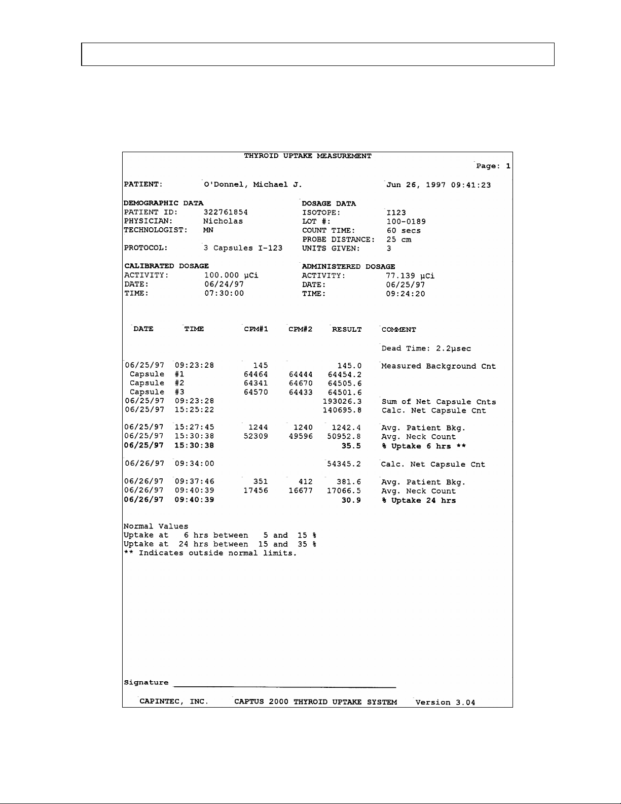
CAPINTEC, INC CAPTUS® 2000
Figure 6-35 shows a typical report in which three capsules are measured for two repetitions
each. Note that the average value is used for the uptake calculation.
Figure 6-35
July 00 THYROID UPTAKE 6-27
Page 94
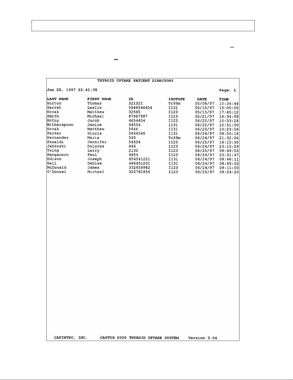
CAPINTEC, INC CAPTUS® 2000
To print all of the patients in the patient library, select Patient List option. Select the PRINT
button to print the desired option. Figure 6-36 represents a typical patient list report.
To exit without printing, select the C
ANCEL button.
Figure 6-36
6-28 THYROID UPTAKE July 00
Page 95
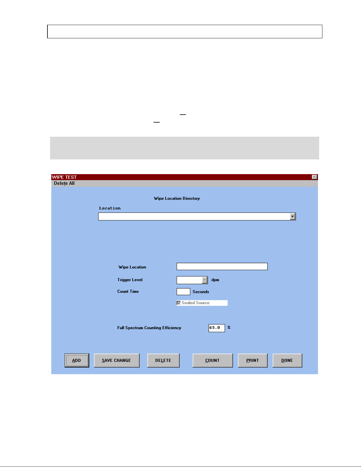
CAPINTEC, INC CAPTUS® 2000
CHAPTER 7
WIPE TESTS
To access the wipe test functions, select the W
Main Menu Screen. After selecting W
Location Directory screen appears, as shown in Figure 7-1.
NOTE: Before using any functions in the Wipe Tests module, perform the System Setup
Procedures outlined in CHAPTER 4: SYSTEM SETUP, and the Quality Assurance
Procedures outlined in CHAPTER 5: QUALITY ASSURANCE.
IPE TESTS from the Main Menu screen, the Wipe
IPE TESTS button from the CAPTUS® 2000
Figure 7-1
From this screen, wipe location and counting parameters are defined, wipe samples are
counted, and result reports are printed.
July 00 WIPE TESTS 7-1
Page 96
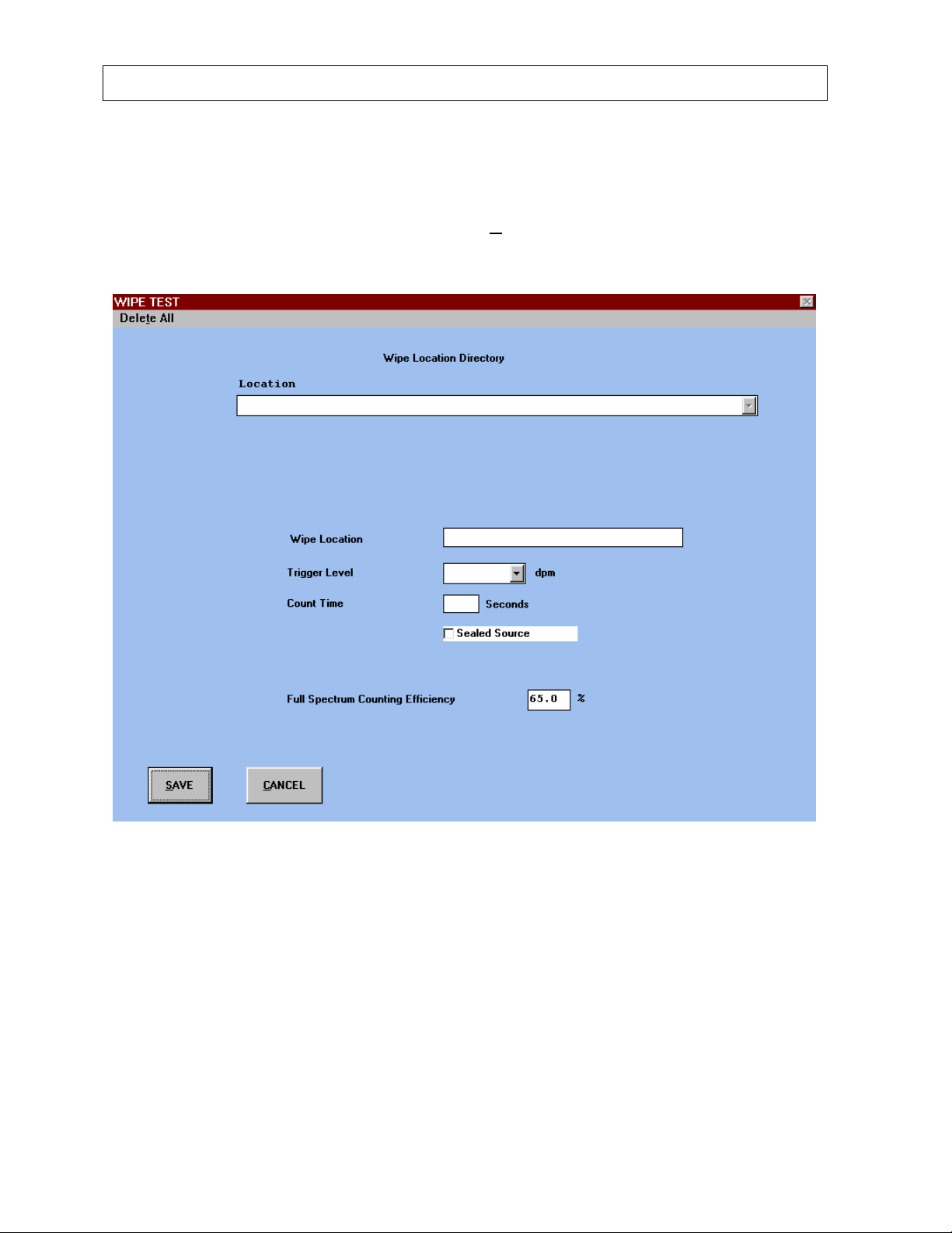
CAPINTEC, INC CAPTUS® 2000
ADDING WIPE LOCATIONS
Before beginning any wipe tests, you must first define wipe test locations, counting times,
and trigger limits. To add a wipe test, choose the A
shown in Figure 7-1. Figure 7-2 will appear.
DD button from the Wipe Location screen
Figure 7-2
Enter the wipe location in alphanumeric characters. The software will first list all numerical
wipe locations in ascending order, then list remaining wipe locations in alphabetical order.
Move from one data field to another by using the Tab key or the trackball indicator. Select
either 200 dpm, 2000 dpm or 22,000 dpm from the Trigger Level drop down box, or type in
any numerical trigger level manually. Next enter the counting time. The counting time is live
time, and must be entered as seconds. Note the Sealed Source check box. If the Sealed
Source check box is selected, and an X or check mark appears in the box, results will be
reported in units of µCi. If the sealed Source check box is not selected, and no X or check
mark appears in the box, then results will be reported in units of dpm.
7-2 WIPE TESTS July 00
Page 97

CAPINTEC, INC CAPTUS® 2000
You may exit the add wipe test screen at any time by selecting the SAVE button. Any
information which has been entered will be saved to the appropriate wipe test data file. If
you do not wish to save the information, choose the C
ANCEL button. The software will
return to the original wipe test location screen without saving any information.
ISOTOPE EFFICIENCY
Efficiency is a measurement parameter which defines the counting losses which occur
between the radioactive rate of decay and the counting rate measured by the system.
Efficiency can be defined as follows:
100minute per counts
Efficiency %
=
The efficiency of an isotope depends upon the geometry, region of interest, energy,
abundance and activity of the source as well as the type of detector system used to measure
the source. For these reasons, efficiency values vary from one isotope to another. The
CAPTUS
®
2000 uses a default value of 65% for full spectrum efficiency. Full spectrum
means the total number of counts detected in all of the MCA channels. This is the nominal
value for whole spectrum efficiency for Tc99m when measured in a 2” × 2” drilled well
detector.
The default value for whole spectrum efficiency can be changed as required. To select an
appropriate whole spectrum efficiency, two methods are suggested. Choose the efficiency of
the isotope which is used most frequently at your facility. For example, general nuclear
medicine facilities use Tc99m most of the time, while nuclear cardiology facilities use Tl201
most of the time. This method will provide an accurate value for most of the wipe tests
measured.
Alternatively, calculate the total spectrum efficiency for several isotopes most frequently
used. Enter the lowest efficiency. This will provide a conservative estimate for activity by
overestimating the activity of most wipes. If no value is entered in the full spectrum efficiency
box, results will only be displayed as cpm.
To calculate total spectrum efficiency, first measure the isotope in the MCA mode. The total
count rate will appear on the MCA spectral printout in units of cpm. Next convert the current
activity of the source measured in the MCA into units of dpm. Remember that 1 µCi = 2.22 x
6
10
dpm. Then calculate the full spectrum efficiency.
The CAPTUS
Efficiency %
®
2000 also measures efficiencies in the Isotope Library, which are used by the
=
automatic peak finding program to provide both the identity and the activity of a peak
identified in the wipe test program.
Note that the Isotope Library measures peak efficiency using only the counts recorded in the
ROI which surrounds the primary photopeak, and does not use total counts. This allows the
×
minute per tionsdisintegra
100minute per counts
×
minute per tionsdisintegra
July 00 WIPE TESTS 7-3
Page 98
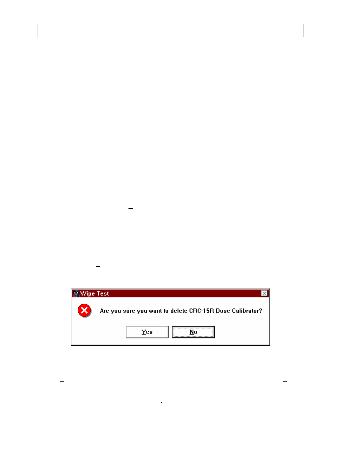
CAPINTEC, INC CAPTUS® 2000
peak finding program to better determine the activity of an isotope when multiple peaks or
isotopes are present. For this reason, the efficiency recorded in the isotope library will
always be lower than the full spectrum efficiency.
In order for the software to identity an isotope in the wipe test, the isotope must be selected
for use in the wipe test program. This selection is also provided in the Isotope Library.
When all isotopes are selected for identification, the automatic peak finding program will
report any isotope whose peak keV is within ± 5% of the energy listed in the Isotope Library.
Since over 60 isotopes are stored in memory, selecting all isotopes does not provide a useful
interpretation of the wipe test results. A recommended procedure is to select for wipe test
identification only those isotopes that are used frequently. Note that all peaks are listed by
energy in the initial wipe results, but only those peaks identified as an isotope are stored in
the wipe test history files.
EDIT INFORMATION
If you wish to review or edit any information which has already been entered for a wipe test,
select the appropriate wipe location from the Wipe Location drop down box. Use the Tab
key or trackball indicator to select the desired text box. The previously entered value will
appear as highlighted. Type over the existing information, and choose the S
button. If you do not select the S
information will not be saved, and the previously entered information will be restored when
you exit the Wipe Test screen.
AVE CHANGE button, any changes made to the wipe test
AVE CHANGE
DELETING WIPE TEST INFORMATION
To delete a single wipe test, first select the desired wipe from the Location drop down box,
then choose the DEL
delete.
Select Y
undo the delete command and return to the previous screen.
To delete all of the wipe tests, choose Delet
the top of the screen. Figure 7-4 will appear and require you to confirm the delete. Select
es to delete all of the wipe test information stored on the selected wipe test, or No to
ETE button. Figure 7-3 will appear and require you to confirm the
Figure 7-3
e All from the menu bar located on the left side of
7-4 WIPE TESTS July 00
Page 99
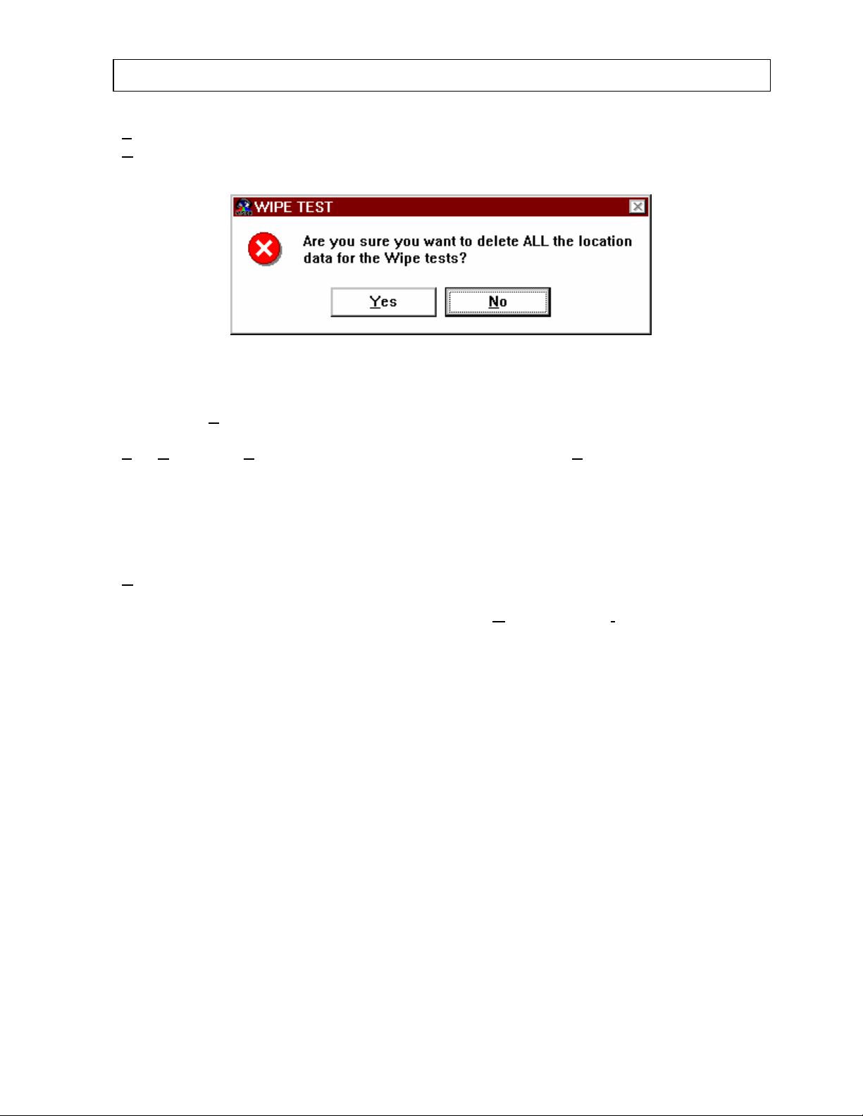
CAPINTEC, INC CAPTUS® 2000
Yes to delete all of the previously entered wipe test location and setup information. Select
N
o to undo the delete command and return to the previous screen.
Figure 7-4
If you select Y
test data CANNOT be undone. Are you absolutely sure you want to delete all the test data?
Y
es No”. Select Yes again to delete all stored wipe test data, or No to undo the delete
command and return to the previous screen.
es, a second similar window will appear with the message, “Deleting all the
MAKING MEASUREMENTS
After entering the wipe test parameters, begin the measurement process by choosing the
C
OUNT button. Figure 7-5, Wipe Data Acquisition screen, will appear.
Note that two items are listed on the menu bar, Go to MCA and Go To Isotope Library.
These allow convenient access to the MCA module or the Isotope Library module without
exiting out of the wipe test program. You can move to the Isotope Library for peak efficiency
measurements or isotope reference information such as photopeak energies or half lives.
The MCA allows you to manipulate or save the spectrum.
July 00 WIPE TESTS 7-5
Page 100
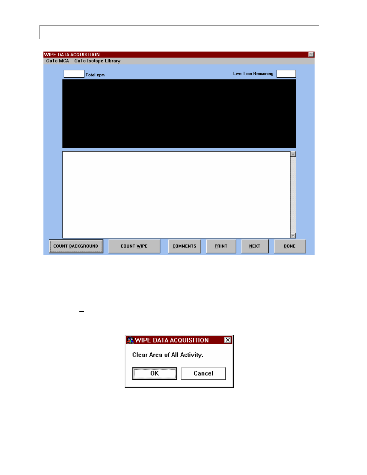
CAPINTEC, INC CAPTUS® 2000
Figure 7-5
Background Measurement
Before measuring a wipe, the CAPTUS
the COUNT B
ACKGROUND button. Figure 7-6 will appear. Select the OK button to
®
2000 requires a background measurement. Choose
proceed with the background count, or the Cancel button to return to the previous screen.
Figure 7-6
7-6 WIPE TESTS July 00
 Loading...