

Page 1

User Manual
DIATHERMY EQUIPMENT
CAPENERGY
FAMILY MODELS
C 50, C 100, C 200
C 300, C 400, C 500
Copyright © CAPENERGY MEDICAL, SLU
TF01-01-B03-A3
REV C- 2015-02
Dec-2015
User Manual
Page 1 of 95
0120
Page 2

Index
Index 2
Introduction 3
Chapter 1 – Description of the device 4
Chapter 2 - Safety 14
Chapter 3 - Installation 21
Chapter 4 – Instructions for use 23
Chapter 5.- Maintenance 39
Chapter 6 - Accessories 48
Chapter 7 – Clinical application 53
Annexes
A – Identification of the CE mark 72
B – Certificate of Delivery and Installation 74
C – Clinical Casuistry Document 76
D – Breakdown Notification 80
E – Warranty Activation 82
F – Electromagnetic Compatibility Considerations (EMC) 83
G – Capenergy Equipment family 87
H – Intellectual Property 94
User Manual
Page 2 of 95
Page 3

INTRODUCTION
CAPENERGY devices are innovative radiofrequency diathermy devices for
physiotherapeutic applications.
This manual provides CIM users with all the necessary information on how to use the
devices, control descriptions, safety precautions, installation and maintenance so they
can use the system and take care of it in a correct way.
This manual does not substitute adequate training in the physiotherapeutic application of
CIM equipments. Capenergy Medical S. L. offers courses on the therapeutic use of the
CAPENERGY equipment range.
This manual includes the following contents:
Chapter 1
Description of the device
A general description of the
CAPENERGY equipment and its
technical specifications.
Chapter 2
Security
Chapter 3
Installation
Chapter 4
Instructions for use
Chapter 5
Maintenance
Chapter 6
Accessories
Contains explanations and instructions
on how to use the CAPENERGY
devices in a secure and safe way.
Explains the electrical, locational, and
environmental requirements for the
installation of CAPENERGY equipment
Describes the use of the CAPENERGY
device
Explains the procedures for the correct
maintenance of the device and its
accessories.
Describes the accessories used with
the CAPENERGY equipment.
Chapter 7
Clinical application
Explains how to perform treatments with
CAPENERGY equipment.
User Manual
Page 3 of 95
Page 4

Chapter 1
Description of the device
This chapter includes an overview of the CAPENERGY equipment family,
including its major components, controls, and technical specifications.
Attention
All personnel that will use this device or perform maintenance on it should read
this manual thoroughly before attempting to use any model of the
CAPENERGY equipment family: C 400, C 300, C 200, C 100, C 500 or C 50.
1.1. INTRODUCTION
CAPENERGY devices are diathermy machines that conduct radiofrequency currents
through contact electrodes for physiotherapeutic applications.
Radiofrequency diathermy occurs when a high frequency electric current circulates
through the human body. This type of high-frequency electrical stimulation produces no
muscle or nerve response: it generates a thermal effect depending on the density of the
circulating current. Thus, the device produces a controlled temperature rise in an area
causing hyperemia, which is one of the desired effects.
Since the 30s, radiofrequency diathermy has become a standard method of physical
therapy and it is being used in other areas of medicine and for surgical applications as
well.
Since the 80s, the offer of Resistive (Direct Coupling) and Capacitive Diathermy devices
has increased further on, with remarkable clinical satisfaction both for operators and
patients.
The RF current is coupled to the human body by means of an insulated or non-insulated
electrode –the active accessory–, which together with the body and the return electrode
–the passive plate– forms an electric circuit, which allows the passage of RF current
through the body areas situated between the two electrodes.
The number of available channels on the different models of the CAPENERGY product
range varies from one to four. When a model has several channels, these operate
independently. Each channel has a keyboard that lets you manage the parameters of
frequency and channel power. It also has two light columns that report the selected
power level and a qualitative indication of the power delivered by the channel.
User Manual
Page 4 of 95
Page 5

The user interface has a screen and a keyboard that allows you to manage several
functions: timer, connected accessories management, state management, energy and
temperature measurements and alarms.
The user interface is organized in a menu system that makes it possible to choose
between the different features available on the equipment.
As a security measure, CIM units have a security control which allows the patient to stop
the RF output of the device immediately.
Before using the equipment, it is important to read the manual.
Feel free to contact us should you have any further questions.
1.2. THE CAPENERGY EQUIPMENT FAMILY
CAPENERGY equipment can be applied to the patient by using manual electrodes
(capacitive / resistive) or automatic plates for rehabilitation treatments and dermatology.
CAPENERGY devices is manufactured in six different models:
C 50
Ref. 5330050
C 100
Ref. 5330001
C 200
Ref. 5330002
C 300
Ref. 5330003
C 400
Ref. 5330004
C 500
Ref. 5330005
Only manual capacitive or resistive device with 1 channel
Automatic or manual capacitive or resistive device with 1 channel
Automatic and manual capacitive and resistive device with 2
channels, for individual or combined use
Automatic and manual capacitive and resistive device with 3
channels, for individual or combined use
Automatic and manual capacitive and resistive device with 4
channels, for individual or combined use
Manual device for URO-GYNECOLOGICAL physiotherapy with
manual intracavitary probe
User Manual
Page 5 of 95
Page 6

1.3. INDICATIONS OF USE
CAPENERGY devices are used for physiotherapy. The following treatments can be
performed:
• Tendinopathy
• Muscle fiber ruptures
• Muscle spams
• Muscle contractures
• Articular ostoarthritic processes
• Pain
• Neuralgia
• Chronic Inflammation
• Fibrosis
• Acute & Chronic inflammatory processes
• Phlebology and oedema
• Injuries
• Cystocele, cystitis, pelvic pain, etc. In Uro-Gynecology
1.4. TREATMENT PARAMETERS
CAPENERGY devices allow the user to adjust the treatment parameters.
These parameters are:
Duration of treatment: Treatment time.
Power: Power delivered by the machine at each output as a percentage of the
maximum power available.
Temperature: Only for accessories with temperature sensor, the device has a
way of working that allows the user to set the target temperature which the sensor
should reach in the active accessory. Consequently, the machine automatically
adjusts the power to maintain the constant temperature read by the active sensor
accessory.
User Manual
Page 6 of 95
Page 7
3 4 5 6
1
2
1.5.- DESCRIPTION OF THE DEVICE
This section describes the C 400 unit, which is the most complete model of the range,
with all the available options described.
The other machines in the CIM range have a similar structure, differing only in the
number of available channels and accessories. See section 1.2 CAPENERGY
equipment Catalog for details.
C 400 is composed of equipment and accessories.
The machine is divided into the following parts:
Front Panel
Back Panel
Front Panel
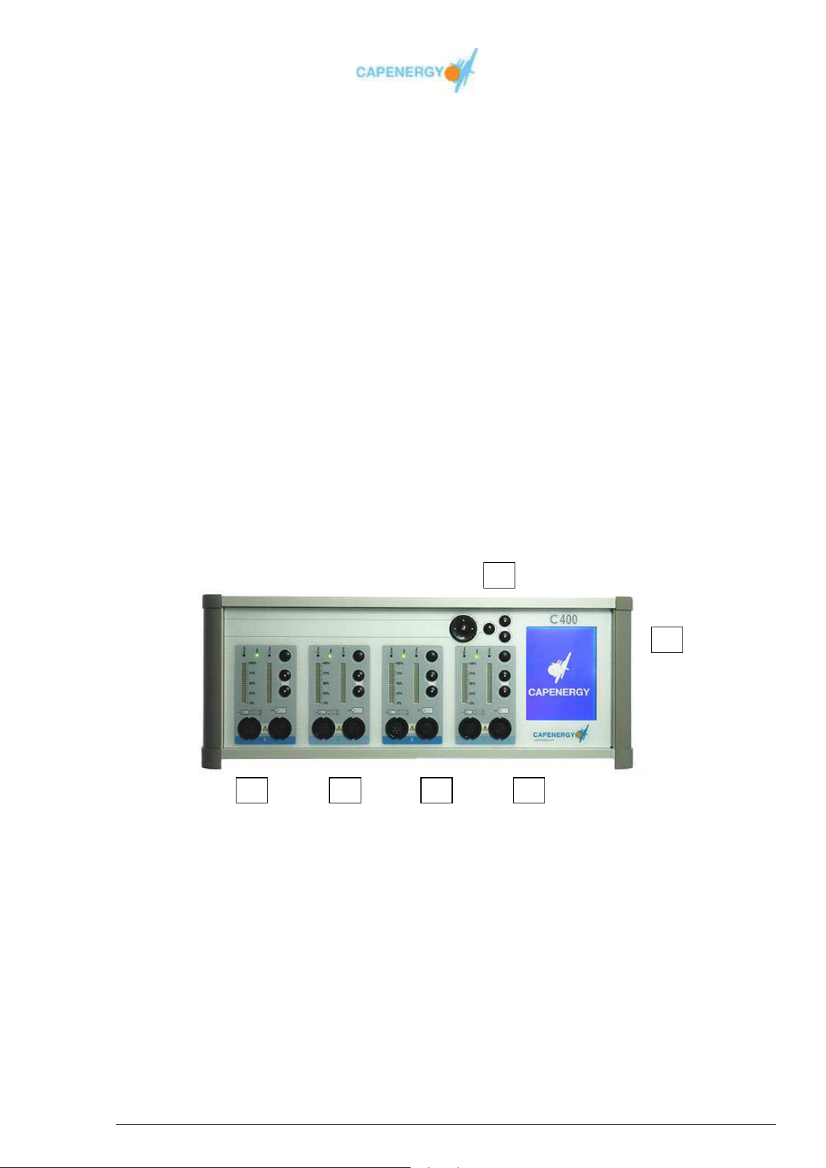
The front panel contains the user interface and the connections for the different
accessories. See image below:
Figure 1.1. Front panel
1.- SCREEN
2.- SCREEN CONTROL BUTTONS
3.- CHANNEL 1
4.- CHANNEL 2
5.- CHANNEL 3
6.- CHANNEL 4
User Manual
Page 7 of 95
Page 8
1
2
3
7
8
5 6
4
2
3
1
6
7 5
4
8
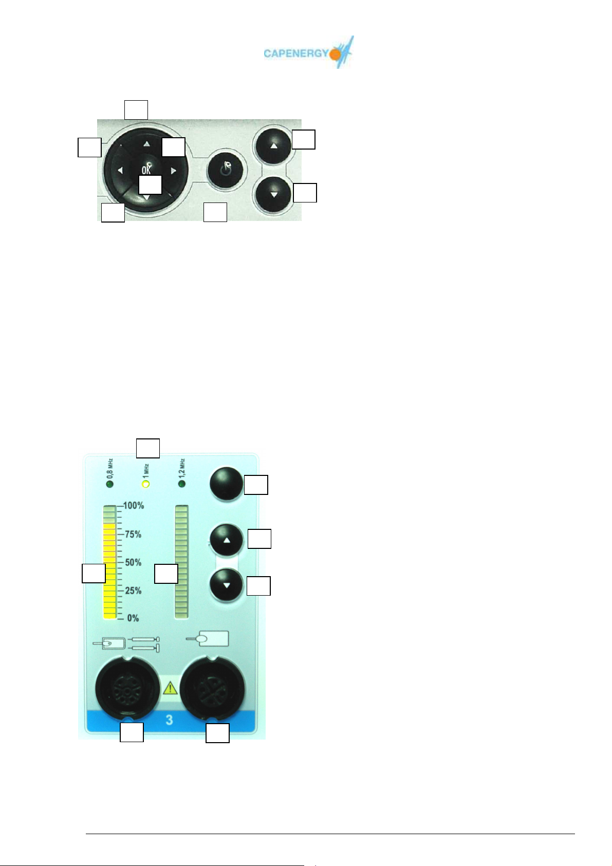
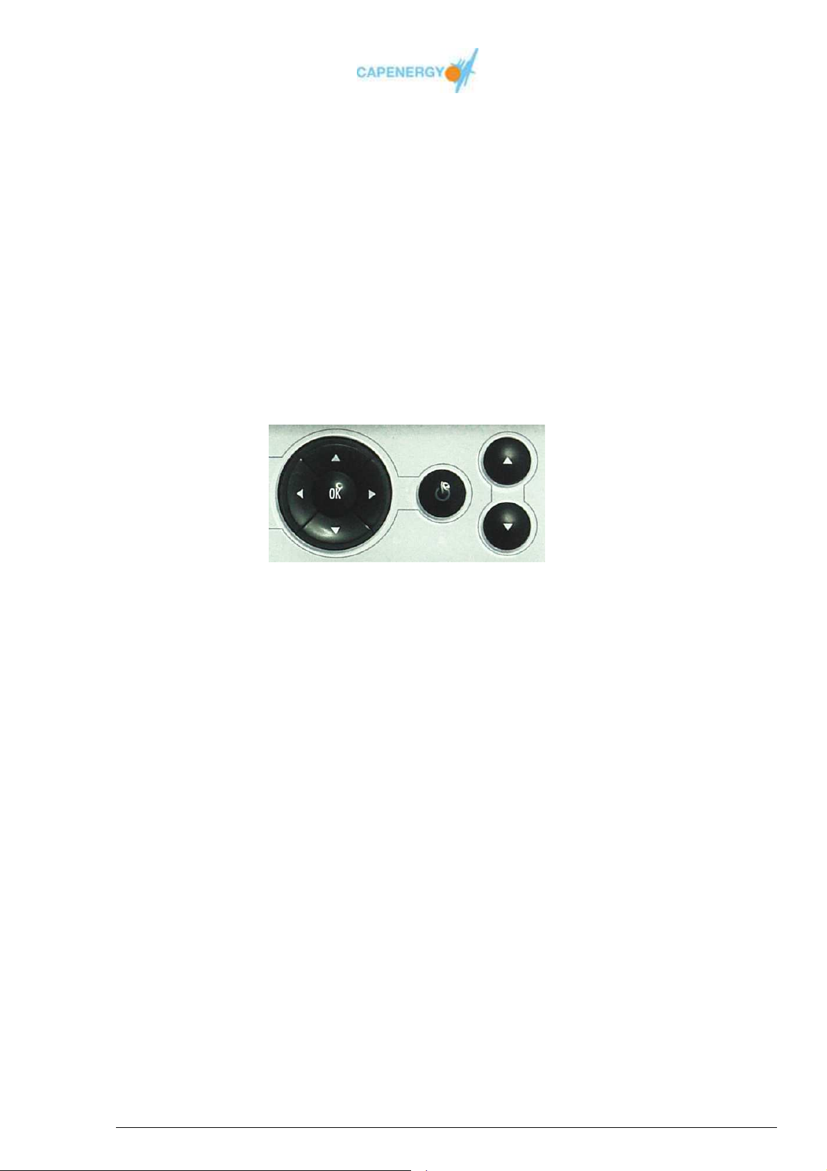
SCREEN CONTROL BUTTONS
Figure 1.2. Screen control buttons
1.-START/STOP button with luminary status indicator:
- START (working): light on
- STOP (not working): light off
2.-Increase treatment time button
3.-Decrease treatment time button
4.-OK button
5.- Left button
6.- Up button
7.- Right button
8.- Down button
CHANNEL
1. Frequency selection button.
2. Temperature or power increase button
3. Temperature or power decrease button
4. Frequency indicator: 0,8MHz, 1,0MHz,
1,2MHz.
5. Luminary indicator of the selected
power percentage
6. Qualitative luminary indicator of the
immediately delivered power.
7. Active accessory connector.
8. Passive plate connector.
Figura 1.3. Channel
User Manual
Page 8 of 95
Page 9
1 3 2
4
1 3 2
4
Back panel
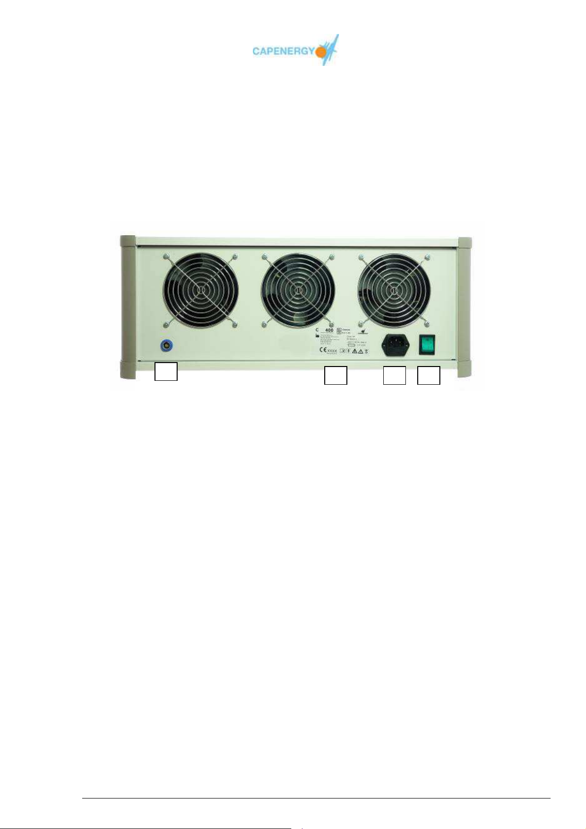
The back panel houses the connection for the safety control as well as the connection for
the network cable. This connector has safety fuses.
Also located in the back panel are the air inlets for the ventilators: they are covered by a
safety grid.
Figura 4. Back panel
1.- On/off switch.
2.- Mains cord connector with safety fuses.
3.- Equipment ID sticker
4.- Safety control connector.
User Manual
Page 9 of 95
Page 10

1.6. ACCESSORIES
The accessories enable the application to the human body of the radiofrequency
currents generated by the device. The device makes use of the accessories’ monopole
topology.
Active accessory: This is the accessory that will be applied to the area under treatment.
There are different types of active accessories.
Insulated accessories: These accessories consist of a holder, which can be
straight or 90º, to which the insulated electrode is connected. The insulated
accessories are available in various diameters. These electrodes should be used
with a protective membrane or cover.
Available diameters
- Insulated electrode 33mm
- Insulated electrode 53mm
- Insulated electrode 65mm
Fixed position insulated accessories. Active plates: Have to be used with a
protective cover. These accessories are fixed to the treatment area by means of
electric bandages.
Non insulated resistive accessories: Theese accessories consist of a holder,
which can be straight or 90º, to which the non-insulated medical degree stainless
steel accessory is connected. The non-insulated accessories are available in
various diameters. These electrodes are used without a protective cover.
Available diameters
- Non-insulated electrode 33mm
- Non-insulated electrode 53mm
- Non-insulated electrode 65mm
Intracavitary acessory: Active accessory designed specially for rectal and
vaginal treatments.
Passive accessory: This accessory is the return plate that allows completing the
electrical circuit so the radiofrequency current can flow.
User Manual
Page 10 of 95
Page 11

1.7. SAFETY CONTROL
CAPENERGY devices are equipped with a safety control. When this safety control is
activated, the device automatically stops generating radiofrequency.
The Safety control acts at two levels simultaneously:
Electromechanical: Activates a relay installed in each channel, which cuts off the
passage of radiofrequency towards the output.
Software: When the safety control is activated, an alarm system is triggered
interrupting the treatment and displaying an alarm message on the equipment
screen.
1.8 SYSTEM SOFTWARE
The software installed on the CAPENERGY devices has the following functions:
It controls the functioning of the device.
It acts as an interface between the user and the device, enabling the selection
of the appropriate parameters for each treatment.
User Manual
Page 11 of 95
Page 12

1.9 SYSTEM SPECIFICATIONS
Electrical characteristics of the device:
• Supply voltage: 230V~
• Supply voltage type: single-phase alternative current (~).
• Power supply frequency: 50 Hz.
Characteristics of the radiofrequency output signal for each channel:
• Frequency:
- 0,8MHz +/-25%
- 1,0 MHz +/-25%
- 1,2 MHz +/-25%
• Maximum output: 45 W +/-10% for a load of 06-j530 ohms to 1 MHz.
• Maximum output tension for a load of 106-j530 ohms: 345 efficient volts.
• Delivered power control: Double control by pulse width modulator and amplitude
control.
• Control signal (PWM) frequency: 10Hz.
Displayed values
• Delivered energy. Expresed in kilojoules. Tolerance +/-20%.
• Temperature in active accessories. Measurement tolerance of +/-2ºC in the
sensor located on the active accesory
Model
Nº of channels
C 400 4 562 mm x 211 mm x 420 mm 22,5 Kg
C 300 3 562 mm x 211 mm x 420 mm 20,3 Kg
C 200 2 220 mm x 211 mm x 420 mm 12,9 Kg
Dimensions
Weight
Max. Power
consumption
800VA
600VA
400VA
C 100 1 220 mm x 211 mm x 420 mm 10,7 Kg 100VA
C 50 1 220 mm x 211 mm x 420 mm 10,7 Kg 100VA
C 500 1 220 mm x 211 mm x 420 mm 10,7 Kg
100VA
The weight referred to in the table above corresponds exclusively to the CIM console,
without taking into account the accessories or the foot. The foot weighs 20 kilos.
The manufacturer reserves the right to make the necessary estimated changes without
notice.
User Manual
Page 12 of 95
Page 13

1.10 ENVIRONMENTAL CONDITIONS
Environmental conditions during the use
When using the device, the following environmental conditions should be present:
• Temperature: 20ºC – 25ºC
• Relative humidity: less than 80%.
• Atmospheric presure: 850mb – 1050 mb
Condicones ambientales for stocking and transportation
• Temperature: 0ºC – 45ºC
• Relative humidity: less than 90%.
• Atmospheric presure: 850mb – 1050 mb
1.11 LIFE SPAN OF CAPENERGY DEVICES
CAPENERGY devices have a life span of 10 years.
User Manual
Page 13 of 95
Page 14

Chapter 2
Safety
This chapter describes safety measures that should be observed when
using CIM and the warnings and precautions to be taken into account by
the user.
Safety warning
2.1 IN GENERAL
CAPENERGY devices are designed in a way that enables the safe application of
radiofrequency current to the human body. When used and maintained appropriately, the
system can be used by trained and qualified personnel in a completely safe way. .
All personnel involved in the use and maintenance of the device should be familiar with
the safety information contained in the manual.
The principal consideration should always be the safety of the patient, the operator and
other personnel.
During the design of the CAPENERGY product range, special attention was given to all
safety elements. What follows is a list of some of the device’s safety mechanisms:
• Intrinsically secure maximum levels of power density
All personnel that is involved in the use or maintenance of CAPENERGY
devices should read and understand this manual in order to become familiar
with all the safety requirements before using the device.
• Safety control for the patient.
• “Watch dog” software safety timer: controls the correct functioning of the software
at all time.
2.2 TECHNICAL WARNINGS AND PRECAUTIONS
Use of the device
• The use of the device is restricted to qualified personnel only.
• The manufacturer cannot be held reliable for the incorrect use of the device.
• Instructions must be kept in the vicinity of the device.
• Before installing and using the device, carefully read the user manual.
• Please check in the annexes the indications on electromagnetic compatibility
according to standard : UNE EN60601-1-2
User Manual
Page 14 of 95
Page 15

Manipulation and Maintenance
• Before connecting the device to the power supply network, make sure you have
the correct voltage: tension overloads may damage the device.
• Before cleaning or performing maintenance on the device, make sure the device
has been disconnected from the power supply.
• Manipulating the device in any way will automatically invalidate the warranty.
• WARNING: No modification of equipment is allowed
Accessories
• The accessories should be used exclusively with the device.
• If an accessory or consumable item presents flaws, it should be taken out of
circulation immediately.
• Periodically check the cables of the accessories to make sure they are in a perfect
state.
• Do not use extension wires for the mains cord.
• The resistive and capacitive electrodes must not be replaced from the electrode
holder when the outputs are actives. The electrodes have to be replaced when the
equipment is en the STANDBY status or turn-off..
External agents
• The device should never be used in the presence of inflammable gases or liquids.
• The device should not be exposed to atmospheric agents.
Technical assistance
• Technical assistance can be performed by the manufacturer or authorized
distributor only.
• The manufacturer and distributor can be held reliable for the product’s safety only
if all repairs, modifications and adjustments have been made by specifically
authorized personnel and the device has been used by qualified personnel only
and according to the safety instructions.
• Only personnel authorized by the manufacturer can service the device, especially
when the interior of the protective covers is concerned. This includes all kinds of
adjustments of the power supply, power and control phases, etc. Dangerous
voltages are present on the inside of the device.
• Before performing maintenance on the device, it should be disconnected from the
power supply. Servicing the device when it’s on, may be dangerous for the user
and / or damage the device.
User Manual
Page 15 of 95
Page 16

2.3 MAIN PRECAUTIONS AND WARNINGS FOR USE:
Regarding the patient:
• The device should not be used on persons with electronic implants such as
pacemakers.
• Do not use on patients with metal implants.
• The device should not be used on patients suffering from infectious bacterial
processes. In case of doubt, consult with a specialist.
• When treatments are performed, the equipment should be used on healthy skin
without wound
Regarding the accessories:
• Always try the distance between plates is greater than 4 cm, considering that
there must always be sufficient body mass between them. Prevent the heart is
between the plates.
• •Put the plates always well supported and the contact to be full with the body,
always looking for the best contact, even in areas with marked changes in relief,
as clavicles, shoulders, etc. Otherwise, with partial contact, may be too much
power concentration in certain parts of the plates, with the risk of burn in skin. It is
very important that the fixation of plates with bands favors the good contact
between its surface and the skin. If the plate is arched in its central zone and only
held fixed by the tips, burns can be produced.
• The plates should never be applied closet o metal objects such as rings, watches
(it is recommendable for the patient to take them off during the treatment).
• When applying, removing or moving the plates, make sure the power output is set
to zero and that all outputs have been shut down. Non observance of this safety
measure may cause skin burns.
• The resistive electrodes should never enter in direct contact with the passive
plate. Non observance of this safety measure may cause the device to shortcircuit.
• The active plates should be used with the protective covers supplied by the
manufacturer.
Regarding the intracavitary accessory:
• The intracavitary accessory must be used with the protective probe cover supplied
by the manufacturer.
• The intracavitary accessory must be inserted into the vagina or the rectum before
increasing the power. You may then proceed with the manipulation.
• It’s convenient for the patient to dispose of the safety control from the first moment
of the treatment on when performing this type of endocavitary treatments.
User Manual
Page 16 of 95
Page 17

2.4 COUNTERINDICATIONS
The use of CAPENERGY devices is counter-indicated in the following cases:
• Presence of pacemakers or other active implants, as cochlear implants, insuline
pump, etc.
• Implanted cables
• Angina
• Epilepsy
• Nervous diseases
• Pregnancy
• Lactation
• Cardiovascular dysfunction
• Neoplasm
• Insensibility to temperature ,even if only temporary
• Decompensated arteriopathies
• Active infectious bacterial processes
• Coagulation problems
• Presence of metal implants (consult with specialist)
2.5 SECONDARY EFFECTS
Healing crisis: If the patient has consumed drugs or other toxical substances (alcohol,
tobacco, etc.) or has a history of liver dysfunction (cirrosis, hepatitis, etc.), there may be
a side side effect at the time of treatment. It has been observed that the treatment may
favor the elimination process of these materials if the device is applied in areas where
there is toxicity. The symptoms are temporary, and can be asthenia, headache, diarrhea
or fatigue in general, depending on the nature of the item being removed. Therefore, it is
appropriate to recommend the intake of plenty of water and rest. At the time that the
circulating elements are removed, the patient returns to normal.
Skin Irritation: In the event of sensitive skin with microcirculation problems, or a history
of smoking, the application of this device may cause skin irritation, if the power applied
by the equipment is excessive. This could produce small microcapillary ruptures, when
there is a lack of capillary flexibility and the blood supply generated by the machine is too
high. For this reason, you should control the power of the device in the event that a
deficiency in the peripheral circulation is detected. Likewise, you may also cause skin
irritation reactions, or even burns if the operator uses the device to infuse different type
of substances (acids, oils, cryogenic substances, thermogenic, anesthetic or abrasive)
with different aims.
User Manual
Page 17 of 95
Page 18

2.6 ELECTRIC AND MECHANIC SAFETY
Maintain all CAPENERGY devices panels and covers closed. The removal of panels or
covers may create hazardous situations.
Inside the device, possibly dangerous high voltages are active. Panels or covers should
not be removed by any personnel other than the authorized technical services.
Never leave a CAPENERGY device on, open or unattended during maintenance.
CAPENERGY devices are heavy and may cause injuries when they are not manipulated
with sufficient care.
The device is earthed by means of the earth conductor of the network cable. Do not ever
connect the device to an installation without a residual-current circuit-breaker.
WARNING: To avoid electric shocks, this device should be connected only to a power
network equipped with an earth conductor.
When using the device it must be located in such a way that the connector of the mains
cord can be easily reached to disconnect it if it is necessary.
User Manual
Page 18 of 95
Page 19
2.7 LABEL
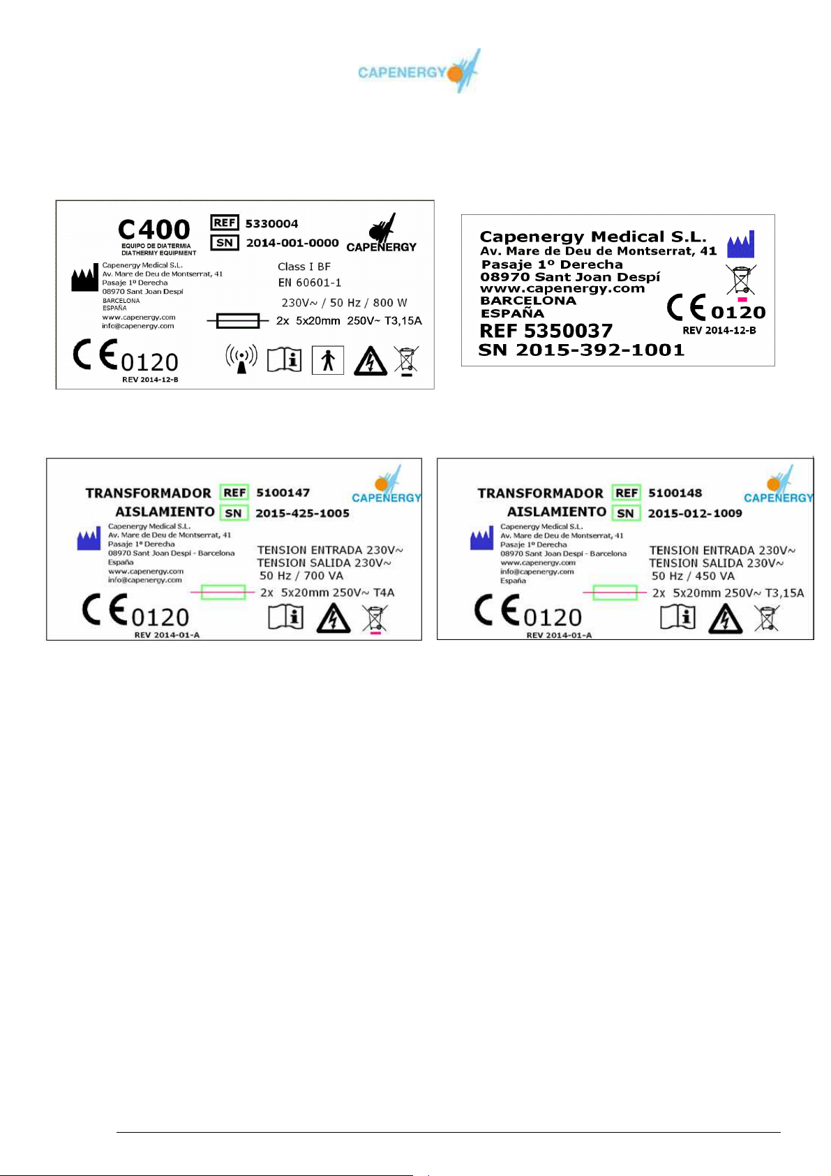
The following label can be found on the C 400 back panel, and accessories, respectively
C 400 label Accessories
Lebel of Isolation transformer of 700VA Lebel of Isolation transformer of 450VA
for devices C300 y C 400. for devices C50, C100, C 200 y C500
Figure 2.1
More detailed information on this matter can be found in Appendix A.
2.8 CLASSIFICATION OF THE DEVICE
• Sanitary device class according to directive 93/42/EEC
• Electric discharge protection: Class I, type BF.
• Protection against penetration of liquids: ordinary device.
• Device not valid for use in the presence of inflammable anesthetic blends.
• Operation mode: continuous
User Manual
Page 19 of 95
Page 20

2.9 MOVING THE DEVICE
All products pertaining to the CAPENERGY product range are equipped with a base on
wheels which allows to easily move the device around, and with breaks allowing to
secure the device.
Before moving any device, make sure all the cables and accessories have correctly been
gathered together and put away in the accessory tray that hangs from the base.
Move the device carefully to avoid obstacles hitting the base.
In case it is necessary to move the CIM 300 or CIM 400, remove all the
accessories and put them away in the accessory tray that hangs from the
base before moving the device.
Safety warning
2.10 CONSIDERATION ON ELECTROMAGNETIC
COMPATIBILITY
The devices pertaining to the CAPENERGY product range: C400, C300, C200, C100,
C50 and C500, require special precautions with regard to electromagnetic compatibility
and need to be installed and used according to the electromagnetic compatibility needs
detailed in this manual.
See annex F for indications and precautions.
2.11 PRECAUTION: DEVICE HEATING DURING USE
When using the device for a long period of time, the upper cover may start heating and
reach temperatures higher than 48ºC.
Safety warning
The upper cover of the device should not be touched for longer than a
minute.
User Manual
Page 20 of 95
Page 21

Chapter 3
Installation
This chapter describes the electrical, spatial and environmental
requirements for the installation of CAPENERGY DEVICES.
The accessories must be in a perfect state when using them for treatments.
In case you detect any flaw, do not use the accessories and replace them by
new ones.
3.1 LOCATION OF THE DEVICE
The device should be located on top of the base that is supplied at the same time as the
device. (In case the model does not come with a base, please locate the device on a
stable table.).
Keep the device away from sources of heat. Maintain sufficient space around the device
in order to guarantee its correct ventilation. Make sure the grids of the back and lower
panel are never obstructed.
Safety warning
3.2 ELECTRICAL REQUIREMENTS
The CAPENERGY product range devices have been designed to work with the following
power supply voltage::
Single-phase 230V~ +/-10%, 4A, 50 Hz
The device is earthed by means of the earth conductor of the mains cord that is inserted
into the connector of the electrical installation. A correct ground connection is vital in
order to assure the device’s safety. Do not ever connect the device to an installation that
does not have a residual-current circuit-breaker.
The supply lines should be free of transitory voltage or current peaks or drops or
surcharges.
The devices incorporates protective fuses of 3,15 A for 230V~ voltage. Each device
contains 2 fuses. In case they melt down, they have to be replaced by fuses of the same
characteristics in order to guarantee safety and reduce fire hazard.
-
Precaution.
Make sure the power supply voltage is the correct one for CIM. Details can be
found on the label located on the back panel.
User Manual
Page 21 of 95
Page 22

3.3 ENVIRONMENTAL REQUIREMENTS
Air quality
CAPENERGY devices need to operate in a non corrosive environment. Corrosive
materials such as acids may damage the electric cables or electronic components.
Metal dust damages electrical devices.
Temperature and humidity
In order for the CAPENERGY devices to operate at their maximum capacity, it is
recommended to maintain the temperature in the room around 20-25ºC, with a relative
humidity lower than 80%. The atmospheric pressure should be maintained in the range
of 850mb to 1050mb.
3.4 ISOLATION TRANSFORMER.
The CAPENERGY product range: C50, C100, C200, C300, C400 and C500, must be
connected the power supply network using the isolation transfomer that is supplied with
them
User Manual
Page 22 of 95
Page 23
Chapter 4
Instructions for use
This chapter describes how to use the CAPENERGY devices and the
menu system that allows selecting and performing various treatments.
4.1. MENU SYSTEM
The user interface is organized in a menu system that allows managing the device’s
configuration and working mode and accessing the information screens.
The navigation buttons and OK button of the screen keyboard, allows surfing through the
different menu options and selecting the desired one.
The following options are available:
Basic mode
Free treatment
Guided treatment
Information
Configuration
The figure shows the flow diagram of the complete system menu.
User Manual
Page 23 of 95
Page 24
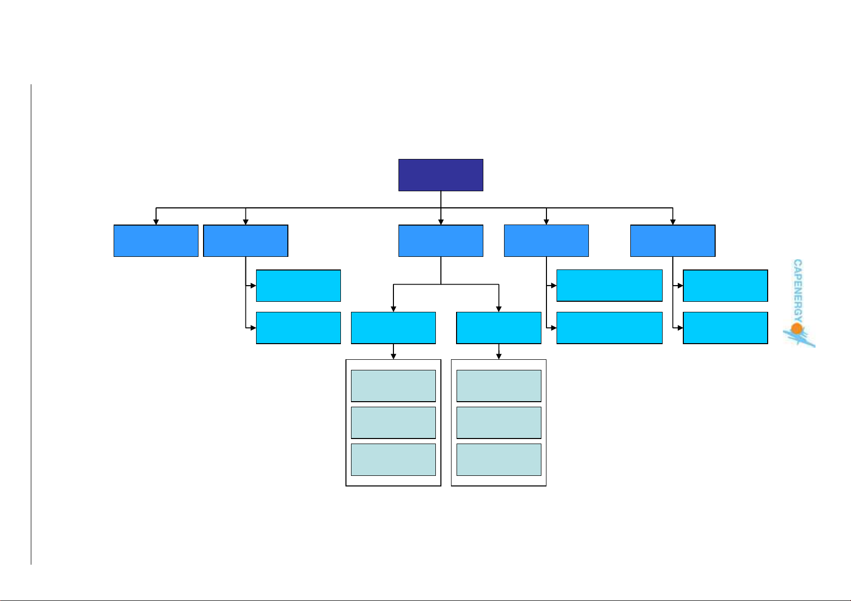
Figure 4.1. Flow diagram of the complete system menu
BASIC MODE
User Manual
Page 24 of 95
FREE
TREATMENT
POWER
CONTROL
TEMPERATURE
CONTROL
INDICATION
CONTROL
ATHERMAL
ATHERMAL
MODERATE
MODERATE
THERMAL
THERMAL
FRANKLY
FRANKLY
THERMAL
THERMAL
SYSTEM
MENU
GUIDED
TREATMENT
TEMPERATURE
CONTROL
ATHERMAL
ATHERMAL
MODERATE
MODERATE
THERMAL
THERMAL
FRANKLY
FRANKLY
THERMAL
THERMAL
INFORMATION
CONTRE-INDICATIONS
MAINTENANCE
CONFIGURATION
SPANISH
ENGLISH
Page 25
4.2. BASIC MODE
In this mode, only the basic working functions are available:
Safety control
Timer
Status
Functioning by power control
Qualitative indication of the instantly delivered energy.
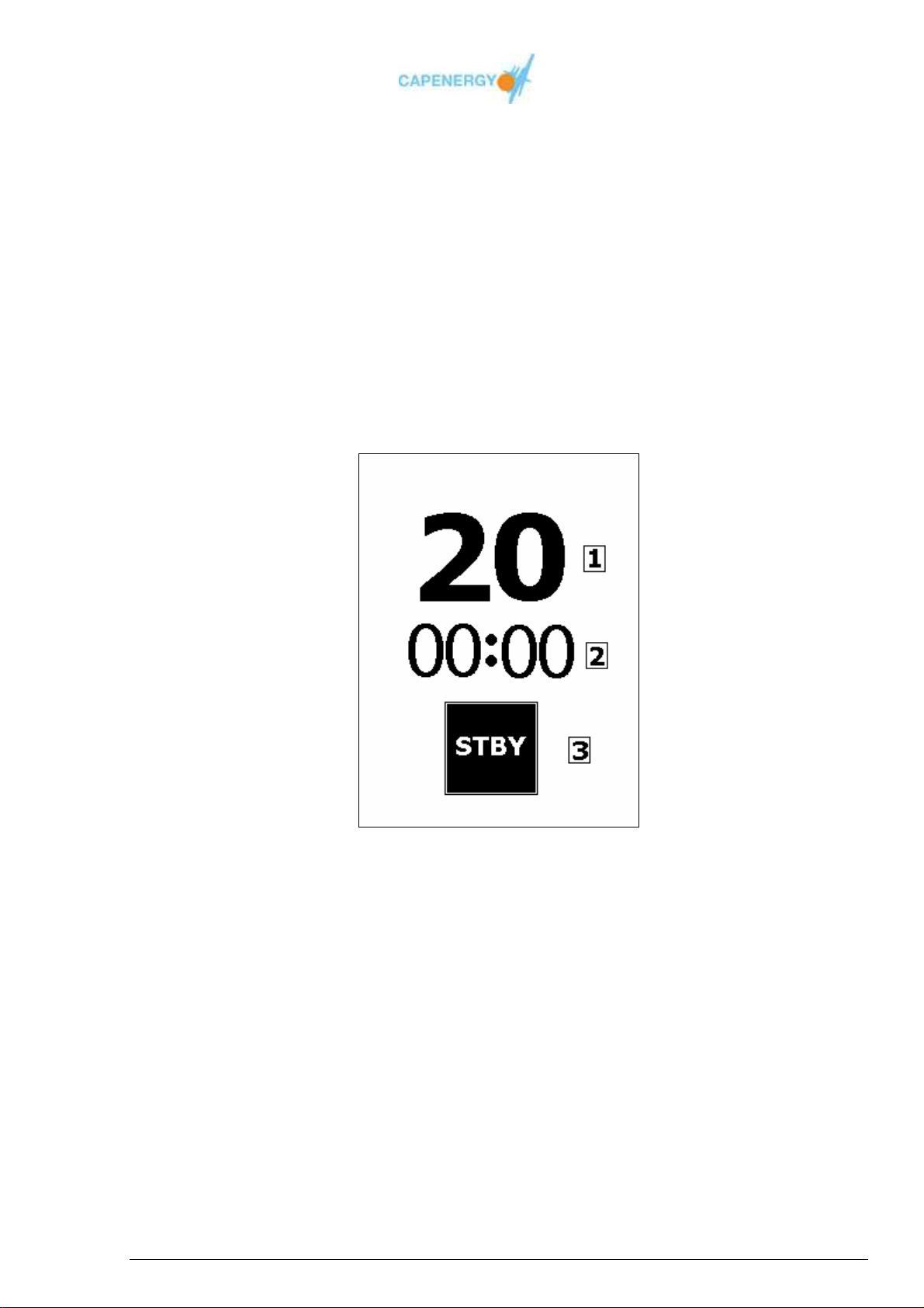
BASIC MODE screen
.
Figure 4.2. BASIC MODE screen
1.- Total treatment time
2.- Elapsed treatment time, expressed in minutes and seconds.
3.- Status.
User Manual
Page 25 of 95
Page 26

BASIC MODE functions description:
Safety control
Control allowing the immediate interruption of the treatment. Works only when
the machine is ON and the outputs are active. When the button of the safety
control is pushed, the safety control warning is activated.
In this case, press the OK button to return to the STANDBY status.
Timer
Total treatment time in minutes
When the device is in STOP status, treatment time can be modified using
the buttons INCREASE / DECREASE treatment time..
Elapsed treatment time
When the device starts WORKING, the elapsed time counter starts running,
expressing elapsed time in minutes and seconds.
Status
The device’s status depends on various factors. The following table details the
possible statuses for the basic mode and how to activate them by means of the
keyboard.
User Manual
Page 26 of 95
Page 27
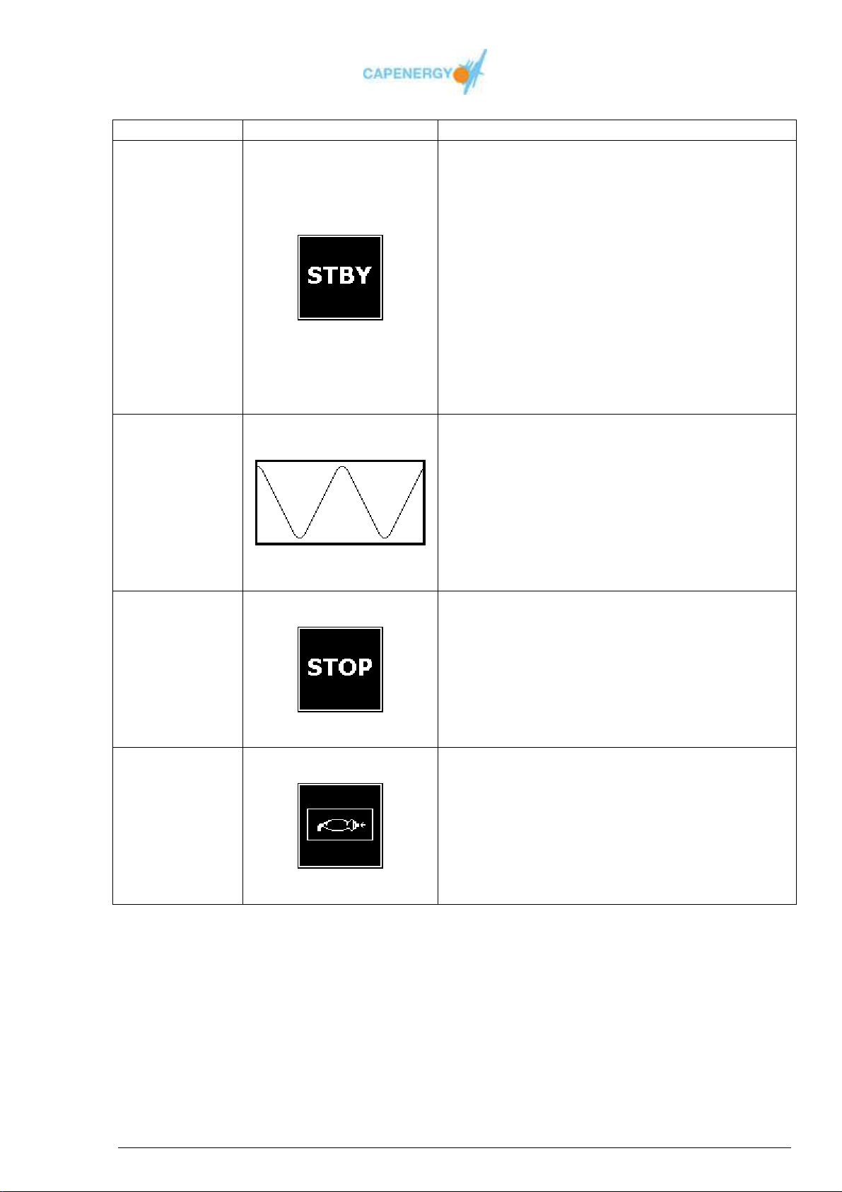
STATUS ICON DESCRIPTION
The otuputs are deactivated.
STBY GRAPHIC
Allows:
Modification of the chosen total treatment
time.
STANDBY
Modification of the power or temperature
configuration of the disabled channels.
Procedure:
Press the button WORKING / STANDBY
to change to WORKING status.
Press the OK button to return to the main
menu.
The outputs are active.
WAVE GRAPHIC
WORKING
Allows:
Power supply modification
Procedure:
Press the WORKING/STANDBY button to
change to STANDBY status.
Treatment time has been completed.
STOP GRAPHIC
TIME
COMPLETED
Warning finalized treatment time.
The outputs have been deactivated.
Procedure:
Press OK to go back to STANDBY
Safety control has been activated
ACTIVE
SAFETY
CONTROL
SAFETY CONTROL GRAPHIC
Outputs have been deactivated.
Procedure:
Press the OK button to return to
STANDBY.
Tabel 4.1. Statuses in BASIC MODE
User Manual
Page 27 of 95
Page 28

Functioning by power control
The power output is established as a percentage of the maximum power by using
the INCREASE / DECREASE power buttons of the corresponding channel. This
can only be done when the device is in WORKING status.
Qualitative indication of the delivered instantaneous power
For each channel, the corresponding luminous indicator informs about the
instantly delivered energy on a qualitative level.
User Manual
Page 28 of 95
Page 29
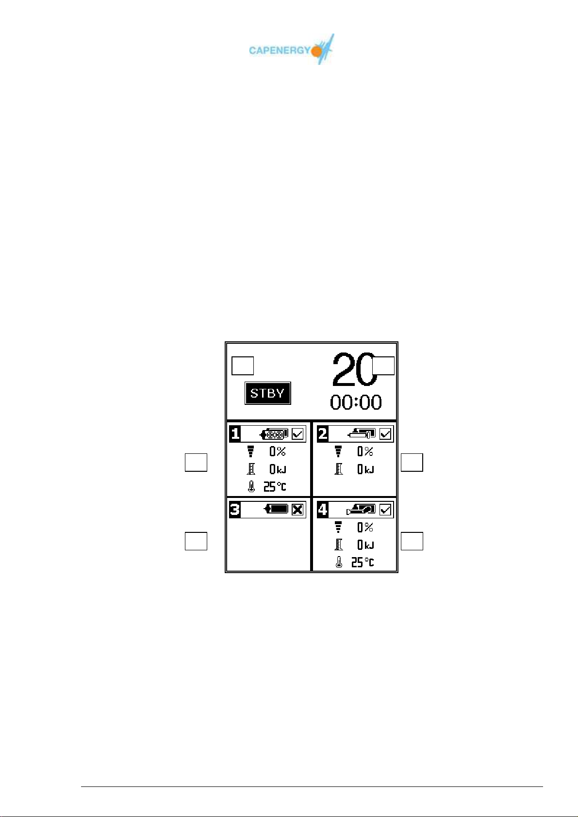
1 2
3 4
5 6
4.3. FREE TREATMENT
This is an advanced treatment mode. In this mode the following functions are available:
Safety control
Timer
Status
Qualitative indication of the instantly delivered energy.
Accessory recognition
Energy measurement
Temperature measurement
Control by power
Control by temperature
Treatment summary screen
FREE TREATMENT screen
Figure 4.3. FREE TREATMENT screen
1.- Timer. This window appears for all models.
2.- Status. This window appears for all models.
3.- Channel 1 This window appears for all models.
4.- Channel 2. This window only appears for C 200 and superior models.
5.- Channel 3. This window only appears for C 300 and C 400
6.- Channel 4. This window appears only for C 400
User Manual
Page 29 of 95
Page 30
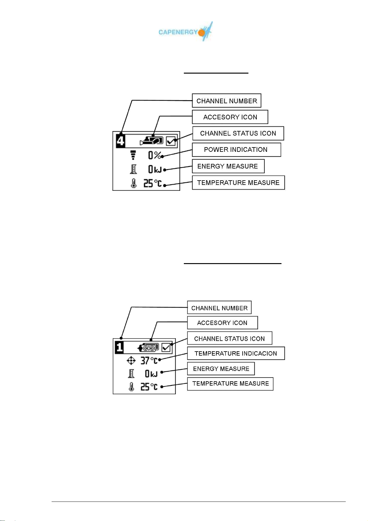
Screen detail FREE TREATMENT MODE
Channel configured by POWER control
Figure 4.4. Channel configured by POWER control.
Screen detail FREE TREATMENT MODE
Channel configured by TEMPERATURE control
Figure 4.5. Channel configured by TEMPERATURE control.
User Manual
Page 30 of 95
Page 31

FREE TREATMENT function description
Safety control
Control allowing the immediate interruption of the treatment. Works only when
the machine is ON and the outputs are active. When the button of the safety
control is pushed, the safety control warning is activated. In this case, press the
OK button to return to the STANDBY status.
Timer
Total treatment time in minutes
When the device is in STOP status, treatment time can be modified using
the buttons INCREASE / DECREASE treatment time..
Elapsed treatment time
When the device starts WORKING, the elapsed time counter starts running,
expressing elapsed time in minutes and seconds.
Status
The device’s status depends on various factors. The following table details the
possible statuses for the basic mode and how to activate them by means of the
keyboard.
User Manual
Page 31 of 95
Page 32
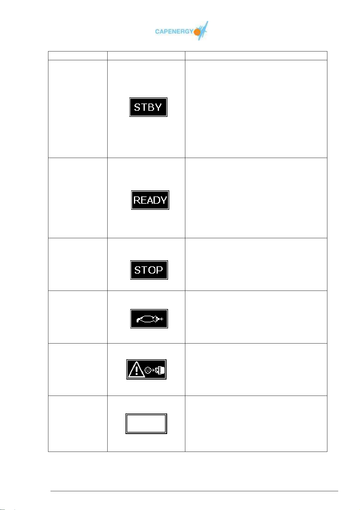
STATUS ICON DESCRIPTION
The outputs are deactivated.
STBY GRAPHIC
Allows:
Modification of the chosen total treatment
time.
Modification of the power or temperature
configuration of the disabled channels.
Procedure:
Press the button WORKING / STANDBY to
change to WORKING status.
Press the OK button to return to the main
menu.
The output are activated.
READY graphic
Allows :
Modification of the disabled total treatment
time.
Modification of the enabled power or
temperature.
Procedure :
Press WORKING/STANDBY button to change
to STANDBY.
Treatment time has been completed
STOP Graphic
Warning finalized treatment time
The outputs have been deactivated
Procedure:
Press OK to go back to STANDBY
Safety control has been activated.
SAFETY CONTROL graphic
The outputs have been deactivated
Procedure :
Press the OK button to return to the
STANDBY status.
Some accessories are wrongly connected
WARNING graphic
While the device is WORKING, an accessory
has been connected or disconnected.
Procedure :
Press the OK button to go to STANDBY.
No valid combination of accessories connected to
the device
EMPTY SQUARE graphic
Procedure:
When connecting a valid combination of
accessories, the device will go in STANDBY
mode.
STANDBY
WORKING
COMPLETED
TIME
ACTIVE
SAFETY
CONTROL
UNALLOWED
CHANGE OF
ACCESSORY
NO
ACCESSORIES
Table 4.2. FREE TREATMENT statuses
User Manual
Page 32 of 95
Page 33
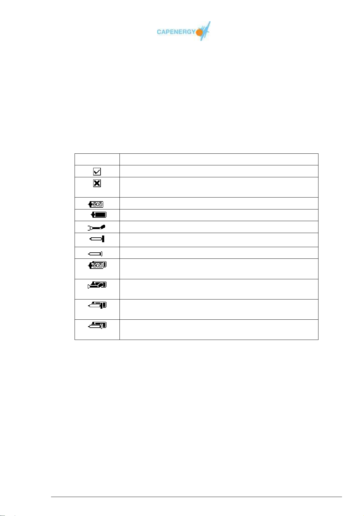
Channel with an invalid combination of connected
Active plate with passive plate. Valid combination of
Qualitative indication of the instantaneous power delivered
For each channel, the corresponding luminous indicator informs about the
instantaneous power delivered on a qualitative level.
Accessory recognition.
The device recognizes the connected accessories, displaying the icon of the
connected accessories for each corresponding channel. When the device is in
WORKING mode, only those channels with a valid combination of accessories will
be activated.
ICON DESCRIPTION
Channel with a valid combination of connected accessories
accessories.
Active plate. Invalid combination of accessories.
Passive plate. Invalid combination of accessories
Intracavitary. Invalid combination of accessories.
Resistive. Invalid combination of accessories.
Capacitive. Invalid combination of accessories.
accessories.
Intracavitary with passive plate.
Valid combination of accessories.
Resistive with passive plate.
Valid combination of accessories.
Capacitive with passive plate.
Valid combination of accessories.
Table 4.3. Channel status icons and accessory icons.
Energy measure
Measure of energy delivered during the treatment, expressed in kilojoules.
Temperature measure
Measure of temperature in the active plate expressed in centigrade grades. This
function is only available for active accessories provided with a temperature
sensor.
User Manual
Page 33 of 95
Page 34

Control by power
The output power is established as a percentage of the maximum power by using
the INCREASE / DECREASE power buttons of the corresponding channel. This
can only be done when the device is in WORKING status.
Control by temperature
In this mode, the user establishes the desired temperature value. The device
automatically regulates the power necessary to reach and maintain this
temperature, measured by the sensor of the active accessory.
This mode only functions in those channels that have accessories with
temperature sensors. Channels with sensor-less accessories connected to them
will function by power control.
The temperature value is established by using the INCREASE / DECREASE
temperature buttons of the corresponding channel.
Indications of the applicable temperature value
For guided treatments, there are three possible temperature options with the
following parameters:
1. Athermal: Corresponds to a power output of 50% with a minimum
generation of heat, indicated for those pathologies where the application of
heat is counter-indicated, especially in acute processes.
2. Moderate thermal: Corresponds to a power output of 75% with a
moderate generation of heat.
3. Frankly thermal: Corresponds to a power output of 100%. The patient will
perceive a strong thermic sensation.
User Manual
Page 34 of 95
Page 35
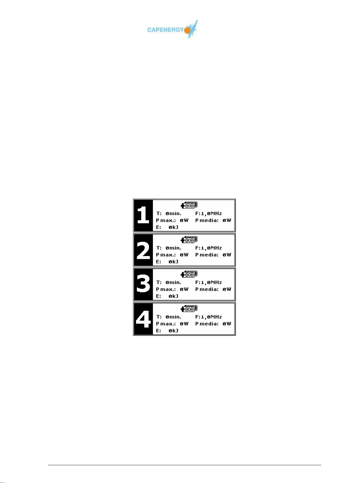
FREE TREATMENT SUMMARY screen
When pressing the button OK after the treatment has come to an end, a SUMMARY
screen will pop up, displaying an overview of the parameters of the treatment that was
performed.
For each channel, the following information will appear:
Connected accessories.
Treatment temperature.
Working frequency of the channel.
Maximum instantaneous power output during the treatment.
Average power output during the treatment.
Total of energy delivered during the treatment.
Figure 4.6. FREE TREATMENT SUMMARY screen.
User Manual
Page 35 of 95
Page 36
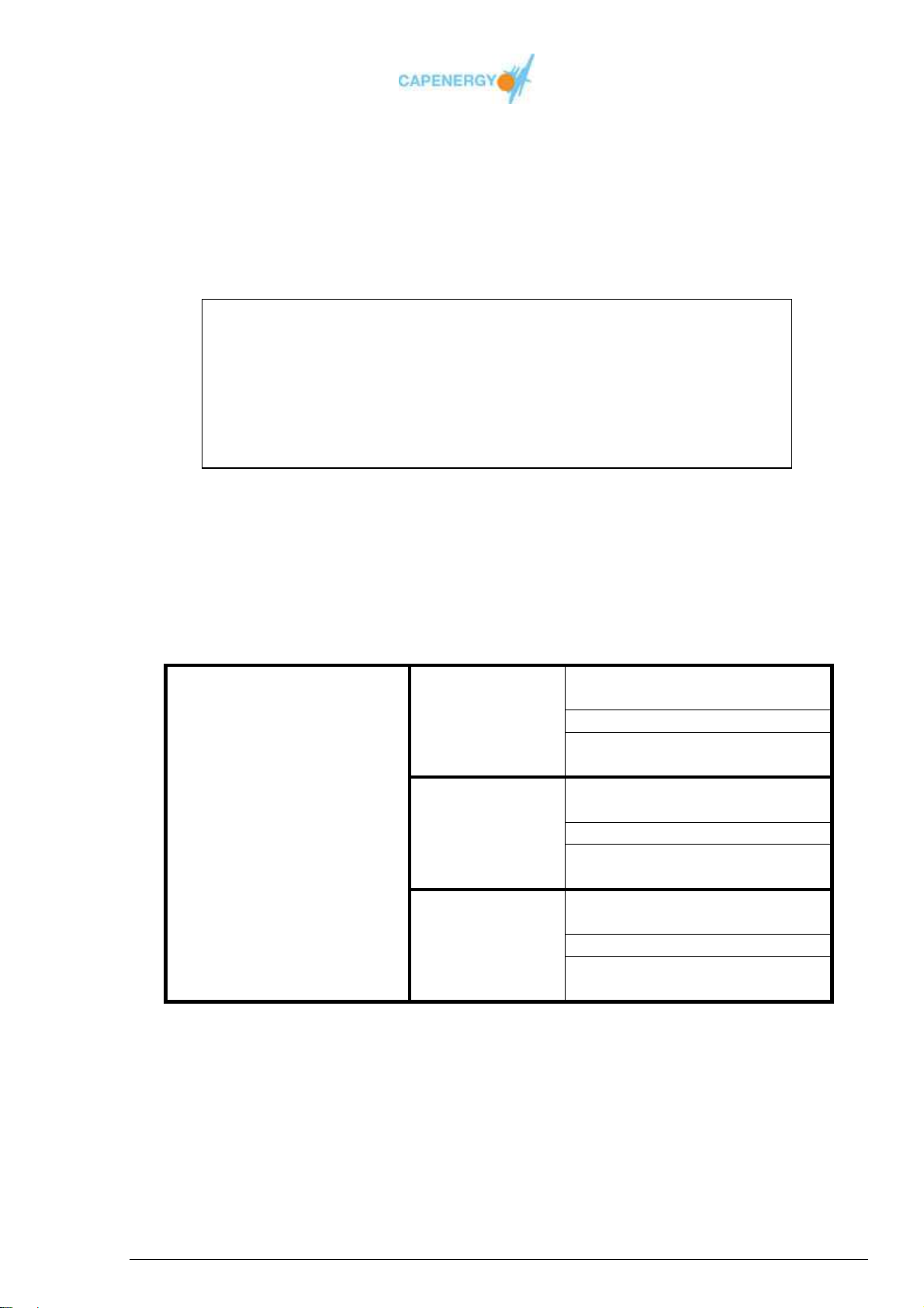
4.4. GUIDED TREATMENT
In this working mode, the device establishes prefixed power output and temperature
values in function of the selected option.
Once the selected option has been activated, the device displays the treatment screen.
From that moment on, the rest of the functions are the same as for the FREE
TREATMENT mode. Please see section 4.3 FREE TREATMENT..
Every application should be pleasant and bearable for the patient. Control
by indication does not free the operator from supervising or the patient
from giving feedback on excessive temperature increases. The patient has
the obligation to inform and to make use of the safety control
Indication control
Fixed values are established for the treatment time, percentage of power output and
working frequency.
There are three options (see table):
INDICATION
CONTROL
Table 4.4. Treatment parameters in case of control by indication.
Warning
Athermal
Moderate
thermal
Frankly thermal
Treatment time:
10 minutes
Selected power output: 50%
Working frequency:
0,8 MHz
Treatment time:
15 minutes
Selected power output: 75%
Working frequency:
1,0 MHz
Treatment time:
20 minutes
Selected power output: 100%
Working frequency:
1,2 MHz
User Manual
Page 36 of 95
Page 37
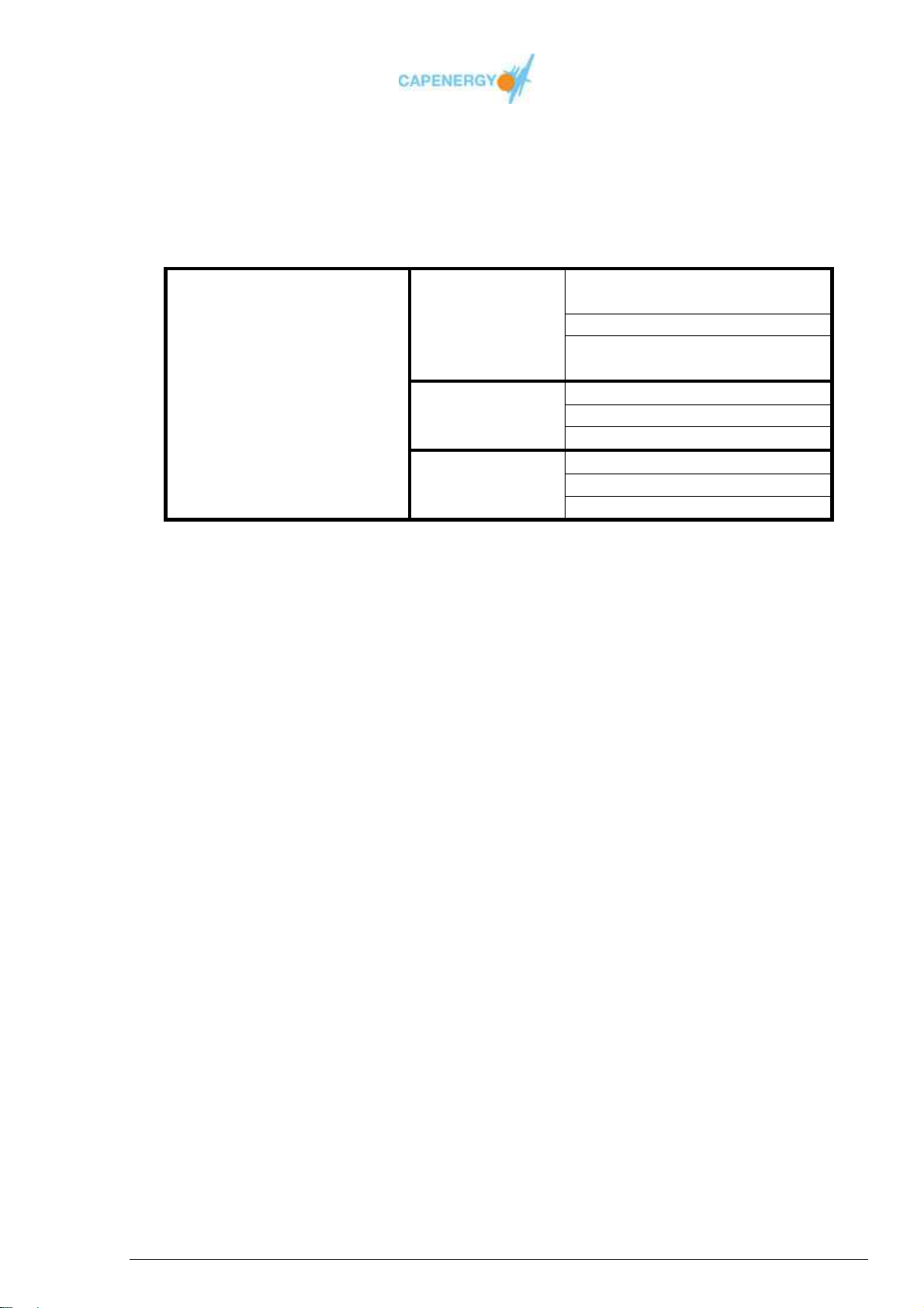
Temperature control
Fixed values are established for the treatment time, temperature and working frequency.
There are three options (see table):
Treatment time:
10 minutes
Athermal
TEMPERATURE
CONTROL
Table 4.5. Treatment parameters in case of control by temperature.
The device automatically regulates the power output necessary to obtain and maintain
the prefixed temperature as detected by the sensor of the active accessory.
This option will be activated only in those channels that have accessories equipped with
a temperature sensor. Channels with sensor-less accessories will be configured
according to the parameters of the INDICATION CONTROL mode.
Moderate
thermal
Frankly thermal
Prefixed temperature: 37ºC
Working frequency:
0,8 MHz
Treatment time: 15 minutes
Prefixed temperature: 39ºC
Working frequency: 1,0 MHz
Treatment time: 20 minutes
Prefixed temperature: 41ºC
Working frequency: 1,2 MHz
4.5.- CONFIGURATION
Allows the selection of the desired language for the menu texts.
Spanish
English
User Manual
Page 37 of 95
Page 38

4.6 - INFORMATION
This menu option gives access to points of interest for the user.
The information screen also displays a QR code through which the manufacturer’s
website can be accessed.
Figure 4.7.QR code .
The available menu options are:
Counter-indications:
Information screen with a list of counter-indications for using the device.
Maintenance:
Information screen with a list of maintenance operations.
This option also displays a QR code through which the manufacturer’s
website can be accessed for further information on technical assistance.
Figure 4.8. QR code
4.7.- SWITCHING OFF THE DEVICE
Before switching off the device with the on/off switch located at the back panel, the
operator must be make sure the device is not in WORKING mode.
User Manual
Page 38 of 95
Page 39

Chapter 5
Maintenance
This chapter describes the procedures for a correct maintenance of the
device and its accessories.
CAPENERGY devices cannot be repaired by users. All repairs should be
made by the manufacturer or authorized personnel.
5.1 IN GENERAL
When using CAPENERGY DEVICES, the following matters regarding periodic
maintenance should be observed:
Before the treatment:
The insulation of the active plate should be inspected carefully in search of
imperfections, damages of the surface, scratches on the insulation or any other kind
of flaw. Do not use the accessory if you detect any kind of damage to the surface of
the gel sleeve, protective membrane or active plate.
The active plates have to be used with gel sleeves. Avoid folds on the inside when
applying the sleeve to the body, in order to avoid pores or cracks from forming.
Any pore or crack in the gel sleeve means you have to get rid of the accessory and
replace it by a new one.
The cables and connectors of the active and passive accessories have to be
inspected to assure their perfect condition. The accessories should not be used in
case any kind of damage or imperfection is detected and they should be replaced by
others in perfect conditions.
The capacitive electrodes should be used with protective membranes to assure their
preservation.
The gel sleeves and protective membranes are consumer goods subject to wear and
tear which may affect safety. Replace the sleeves and membranes by new ones if
you observe any flaws.
Warning
User Manual
Page 39 of 95
Page 40

After the treatment:
The resistive electrodes do not have to be used with a protective membrane. They
are best cleaned with a class IIa disinfecting product.
The passive plates are not to be used with a gel sleeve. They are best cleaned with a
class IIa disinfecting product after each application.
After each treatment, it is mandatory to carefully and correctly clean all the electrodes
and active and passive plates. This will considerably increase the life span of the
product.
Do not use aggressive products such as acids, liquid ammonia, alcohol, etc. to clean
the external surfaces of the device.
We recommend a periodical inspection of all the components of the device. Contact
your official distributor in case you detect any anomaly.
The disinfecting product used must be sanitary product of class IIa and it must be used
following the instructions of his manufacturer.
5.2 SPECIFIC CONSIDERATIONS FOR INTRACAVITARY
TREATMENT.
Treatments carried out with intracavitary electrode require the use of an eco-cover or
covering sensor of anal and vaginal use, being very important when it is put on the
electrode the inside air is expelled for a better inductively coupled, recalling that for
these treatments is not required inner gel between the electrode and eco-covers or
covering sensor. The gel is only for outdoor use for better intracavitary sliding and to
favor the inductively coupled during treatment.
Eco-covers or covering sensor of anal and vaginal use are recommended by
CAPENERGY MEDICAL validated for treatments to be performed. Any other material
used by professional expose to the risk of burns or bad inductively coupled of the
equipment under their full and sole responsibility.
The recommended gel for use in intracavitary applications is validated by the
manufacturer with the presentation format single-dose sterile. Any other material
used by professional expose to the risk of burns or bad inductively coupled of the
equipment under their full and sole responsibility.
References validated the eco-covers or covering sensor of anal and vaginal use, and
the gel in sterile single-dose of intracavitary use are specified in "6.1
ACCESSORIES".
User Manual
Page 40 of 95
Page 41

5.3 MAINTENANCE ROUTINES INTERVALS
In the following table you will find an overview of the necessary periodical maintenance
routines for C 400 devices (and the entire product range).
Frequency Task Executed by
Each 5 years. General revision of the equipment.
After each
treatment
Before each
treatment
Monthly
Verification and checking of the
parameters of power, frequency and
temperature.
Clean the treatment accessories.
Inspection of the active plate’s gel sleeve.
Inspection of the insulation of the active
plate and the integrity of the passive plate.
Inspection of the insulation of the
capacitive electrodes.
Inspection of the accessories’ cables and
connections.
Check the correct functionality of the
safety control
Inspection of the central unit.
MANUFACTURER
USER
User Manual
Page 41 of 95
Page 42

5.4 PROBLEM SOLVING
Problem Probable cause Action
The screen does not
light up when the
device is switched on.
The accessories have
been applied correctly,
the device is ON and the
power has been set to the
maximum, but the power
indicating pilot light does
not light up.
When the equipment is
turned on, the following
message appears in the
screen:
ERROR #
During the treatment
appears the following
message:
OVERLOAD #
The socket does not
receive electricity.
One or two fuses have
melted down.
Electronic breakdown
The passive or active
plates are not
connected correctly.
The passive or active
plates are defect.
Electronic breakdown
A malfunctions has
been detected in the
initial test routine.
The selected power is
to high in the indicated
channel.
Electronic breakdown
Check whether the socket
receives electricity. Make
sure the mains cable is
connected correctly.
Replace the melted fuse(s)
of the network base.
Contact the technical
service department.
Make sure the passive plate
and active accessory are
connected correctly to their
corresponding connectors.
Change the passive plate
and active accessory to see
if this solves the problem.
Contact the technical
service department.
Contact the technical
service department.
Restart the treatment and
use a smaller power.
Contact the technical
service department.
User Manual
Page 42 of 95
Page 43

Problem Probable cause Action
The device does not
recognize an accessory
or does not identify it
correctly.
The temperature level
of the active accessory
connected to a channel
is not correct.
The passive plate or
active accessory, are
not connected correctly.
Defect accessory.
Electronical breakdown.
The active accessory is
not connected correctly.
Defect accessory.
Electronical breakdown.
Make sure the passive plate
or active accessory are
connected correctly to their
corresponding connectors.
Try to connect the
accessory to another
channel. If the problem
persists, replace the defect
accessory for a good
working one.
Try to connect an
accessory that is identified
correctly when connected to
another channel. If it is not
identified correctly, contact
the technical service
department.
Make sure the active
accessory is connected
correctly to its connector.
Try the accessory in
another channel, if the
problem persists, replace
the defect accessory for a
new one.
Connect an active
accessory that works
correctly in another channel
to the channel you are
having problems with. If the
problem persists, contact
the technical service
department.
User Manual
Page 43 of 95
Page 44

5.5 AVAILABILITY OF TECHNICAL INFORMATION
If requested, circuit diagrams, component lists, descriptions, instructions for calibration
and other information can be supplied in order to help adequately qualified personnel to
repair those parts of the device the manufacturer considers repairable.
Warning
CAPENERGY devices cannot be repaired by users. All
repairs should be made by the manufacturer or authorized
5.6 MANUFACTURER’S LIABILITY
CAPENERGY MEDICAL, S.L. is responsible for the safety, reliability and correct
functioning of the device only when:
Assembly, extensions, adjustments, modifications or repairs are carried out by
personnel specifically authorized by CAPENERGY MEDICAL, S.L.
The electrical installation of the rooms where the device is connected comply all
requirements.
The device is used according to the instructions explained in detail in this manual.
The manufacturer cannot be held liable for damages caused to persons or effects
derived from an incorrect use of the device, lack of or incorrect maintenance or failure to
observe the guidelines contained in this manual.
5.7 MANUFACTURER’S WARRANTY
The devices of the CAPENERGY product range (console) has a 24 month warranty
period starting from the date of purchase. The warranty is invalidated if the device is
operated, serviced or manipulated by personnel unauthorized or negligence occurs
during use of the device.
The accessories (electrode holder, active and passive plates and capacitive and resistive
electrodes) have a warranty of 12 months from the date of purchase. This warranty is
invalidated by manipulations, interventions or modifications of the devices carried out by
unauthorized personnel or by negligent use of the accessories.
User Manual
Page 44 of 95
Page 45

The consumable items (membranes and protecting sleeves) that enter into contact with
the patient’s body are subject to normal wear and tear and have a guarantee of 6 months
following the purchase only if they have not been used, have not been subject to
manipulations, interventions or modifications by unauthorized personnel and have not
been used in a negligent way.
The warranty is limited to repair free of charge and the replacement of those parts in
which Capenergy Medical, S.L.’s technical personnel detects possible manufacturing
defects.
This warranty does not cover parts, accessories or consumable goods subject to use
and/or wear and tear due to normal use or those parts, accessories or consumable
goods damaged due to an incorrect use or maintenance.
Repairs derived from mechanical crashes, natural catastrophes, defects in the electrical
installation or improper use are not covered by warranty. Any kind of manipulation,
maintenance and / or repairs carried out by unauthorized personnel will automatically
invalidate the warranty..
5.8 OBSERVANCE OF THE WARRANTY CONDITIONS FOR
THE BUYER
1. The buyer commits to verifying the correct state of the merchandise within 24 hours
after reception.
2. Possible damages occurred during transport must be communicated immediately in
writing to the transport agency that has made the delivery as well as to the sender.
Anomalies and/or damages caused by transport are never covered by warranty.
3. The warranty is activated when the certificate of installation, duly signed by the
customer and the seller, is sent to the manufacturer. Failure to present this document
will mean all repairs and revisions of the device will be charged correspondently (will
not be free of charge), even within the period of warranty.
4. The warranty does not cover accessories subject to wear and tear (active and
passive plates, cables, electrodes, etc.) Nevertheless, if the customer detects and
informs about any defect in the accessories in a period of 30 days after purchase, the
accessories will be replaced by new ones prior return to the manufacturer of the
defect items.
5. The device has to be sent to the manufacturer / distributor in its original packaging. In
case the shipment is made by a transport agency, the wooden box has to be secured
on a pallet.
User Manual
Page 45 of 95
Page 46

6. The warranty does not cover defects caused by negligence or lack of adequate care
during use due to the non-observance of the instructions detailed in this manual, be it
because of incorrect maintenance or any other circumstance that is not caused by
manufacturing defects.
7. The manufacturer cannot be held liable for damages to persons or objects derived
directly or indirectly from the lack of observance of all the prescriptions detailed in this
manual and specifically in regard to the use and maintenance of the device. The
guaranty does not provide, in any case, for the compensation of damages, of any
nature, suffered by persons or objects.
8. The warranty will become invalid and technical assistance will only be provided at the
customer’s charge, in the following cases:
In case the buyer is unable to present the warranty certificate;
In case the device has been given an inappropriate use;
In case the serial number has been erased, tampered with or eroded;
In case the casing of the device has been opened up by unauthorized
personnel;
In case the device has been manipulated, even if only partially or only one of
its parts or components.
9. In case of assistance under warranty, all the costs and risks derived from the
transport of the device are at charge of the customer.
10. In case the technical service does not detect any manufacturing defects, all costs
derived from the revision will be at charge of the customer, even if the device is still
under warranty.
11. The warranty conditions cannot be modified by any other written or oral agreement.
12. Assistance under warranty can only be carried out by the manufacturer or certified
personnel specifically authorized to do so by the manufacturer..
13. We recommend you periodically revise your devices once the warranty period has
come to an end. We recommend you have this check-up every two years in order to
assure the correct working and efficiency of the device and its accessories.
User Manual
Page 46 of 95
Page 47

5.9 TECHNICAL SERVICE
For any further information on the use of the device and / or technical service, please
contact us directly:
CAPENERGY MEDICAL S. L.
Av. Mare de Déu de Montserrat, 41 - Pasaje 1º Derecha
Polígono Industrial Font Santa
08970 Sant Joan Despí (Barcelona)
España (SPAIN)
Tel. : + 34 (93) 477.43.48
Fax : + 34 (93) 477.42.90
[email protected]
5.10 HOW TO DEAL WITH THE DEVICE AND ITS
ACCESSORIES AT THE END OF ITS LIFE CYCLE
Once the life cycle of the device has been completed, kindly dispose of it according to
the Waste Electrical and Electronic Equipment Directive (WEEE) , 2002/96/CE, this law
came into force in August, 13- 2005 in the European Community.
This directive set collection, recycling and recovery targets for all types of electrical and
electronics goods for reducing pollution.
User Manual
Page 47 of 95
Page 48
Chapter 6
Accessories
This chapter details the accessories and consumable items available for C
400.
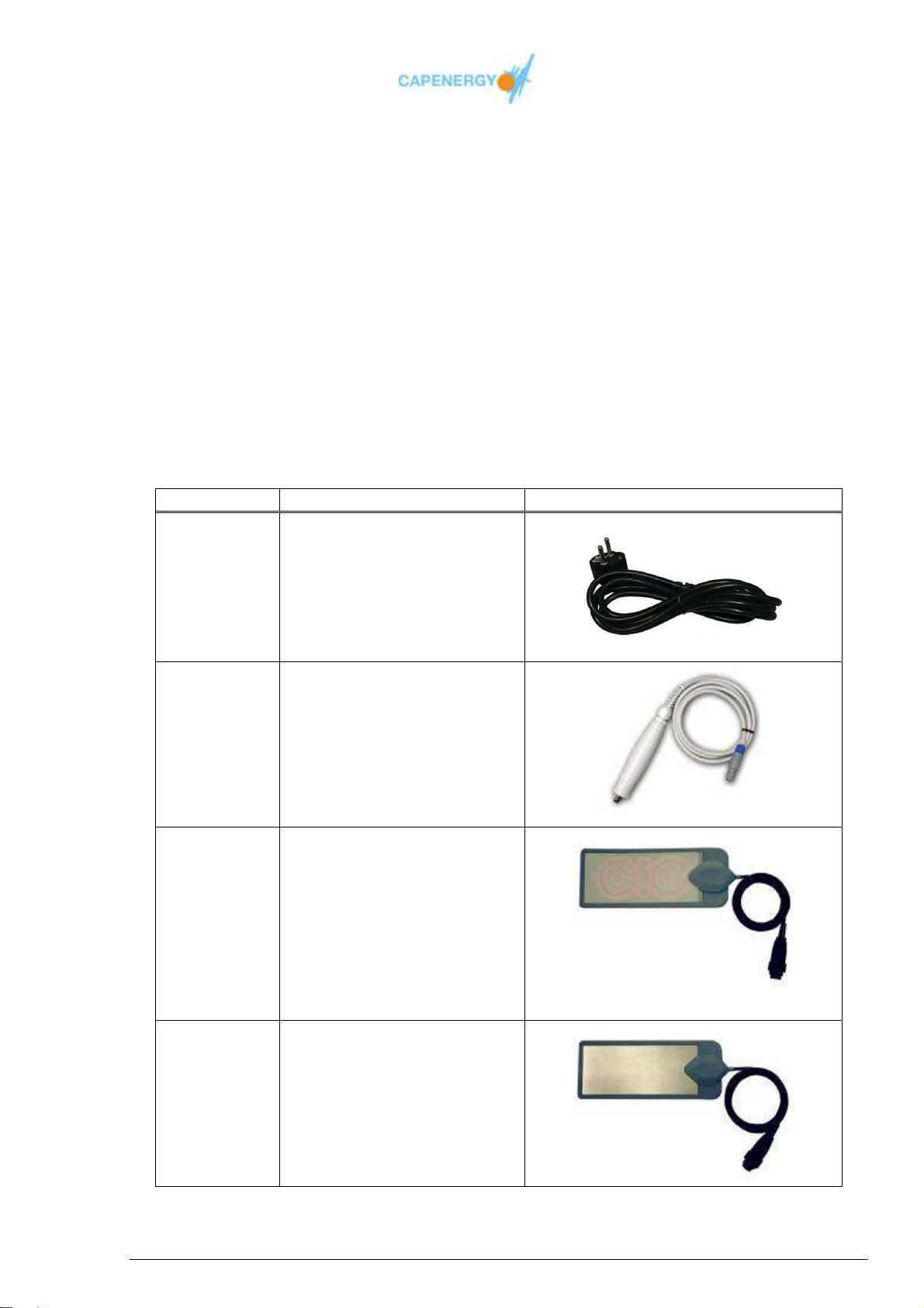
6.1 ACCESSORIES
The following table details the available accessories:
WARNING. The use of ACCESSORIES, electrodes and cables different from those
indicated in this manual may increase the EMISIONS or decrease the INMUNITY of the
equipments of the CAPENERGY product range: C400, C300, C200, C100, C50 and
C500.
Reference Description Image
080224 Mains cord
2,5 meters
5350070 Safety control
5350037
5350037 XL
5350038
5350038 XL
Active plate with
temperature sensor. (180
cm long)
(Optional)
Maximum length cable 200
cm
Passive plate (180 cm
long)
(Optional)
Maximum length cable 200
cm
User Manual
Page 48 of 95
Page 49
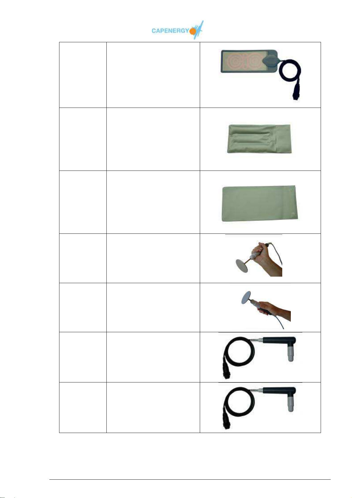
made out of polyurethane
5350039
5350039 XL
Active plate without
temperature sensor (180
cm long)
(Optional)
Maximum length cable 200
cm
5100013 Hygienic protective cover
made out of polyurethane
with conductor gel for
active plate.
5100060 Hygienic protective cover
without conductor gel for
active plate.
5350033
5350033 XL
5350034
5350034 XL
5350035
5350035 XL
5350036
5350036 XL
Straight resistive electrode
holder (180 cm)
(Optional)
Maximum length cable 200
cm
Straight capacitive
electrode holder (180 cm)
(Optional)
Maximum length cable 200
cm.
90º resistive electrode
holder (180 cm)
(Optional)
Maximum length cable 200
cm.
90º capacitive electrode
holder (180 cm)
(Optional)
Maximum length cable 200
cm.
User Manual
Page 49 of 95
Page 50
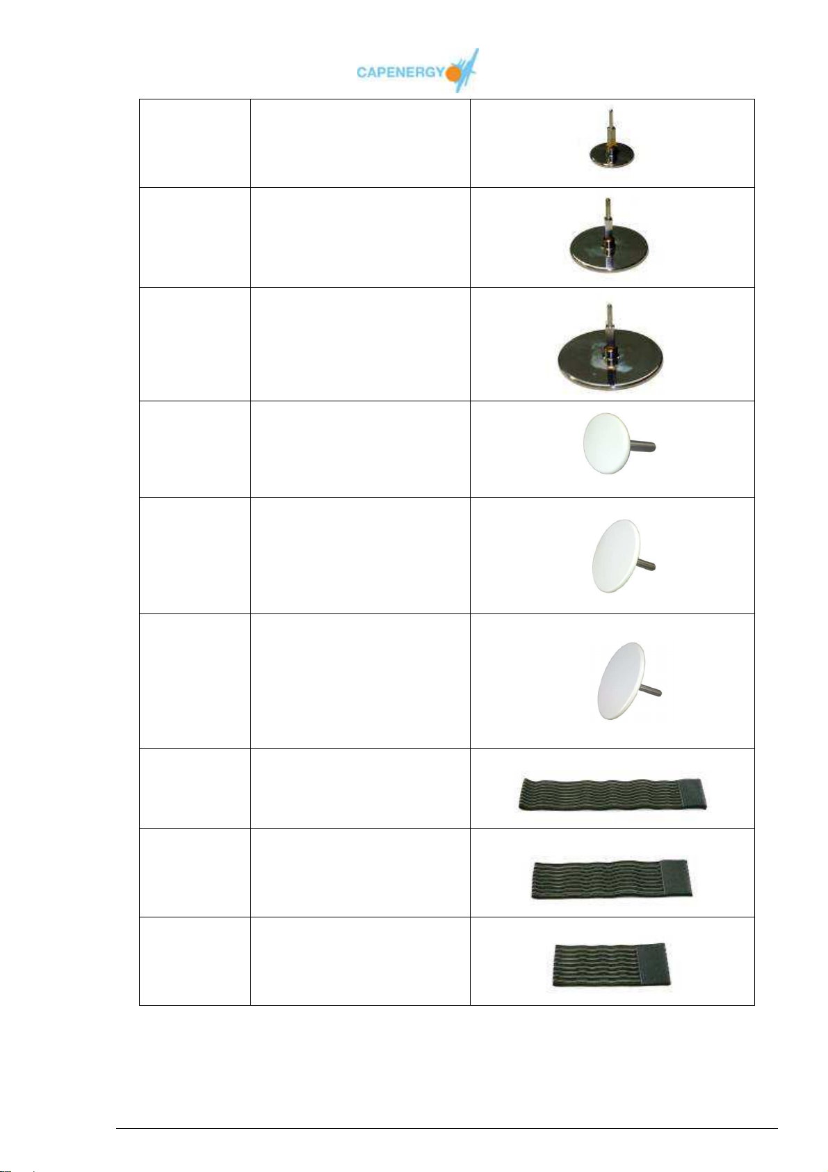
5100029 Resistive electrode 33mm
5100031 Resistive electrode 53mm
5100032 Resistive electrode 65mm
5100025 Capacitive electrode 33mm
5100027 Capacitive electrode 53mm
5100028 Capacitive electrode 65mm
5111028 Elastic strap 80 cm
5111030 Elastic strap 60 cm
5111029 Elastic strap 40 cm
User Manual
Page 50 of 95
Page 51
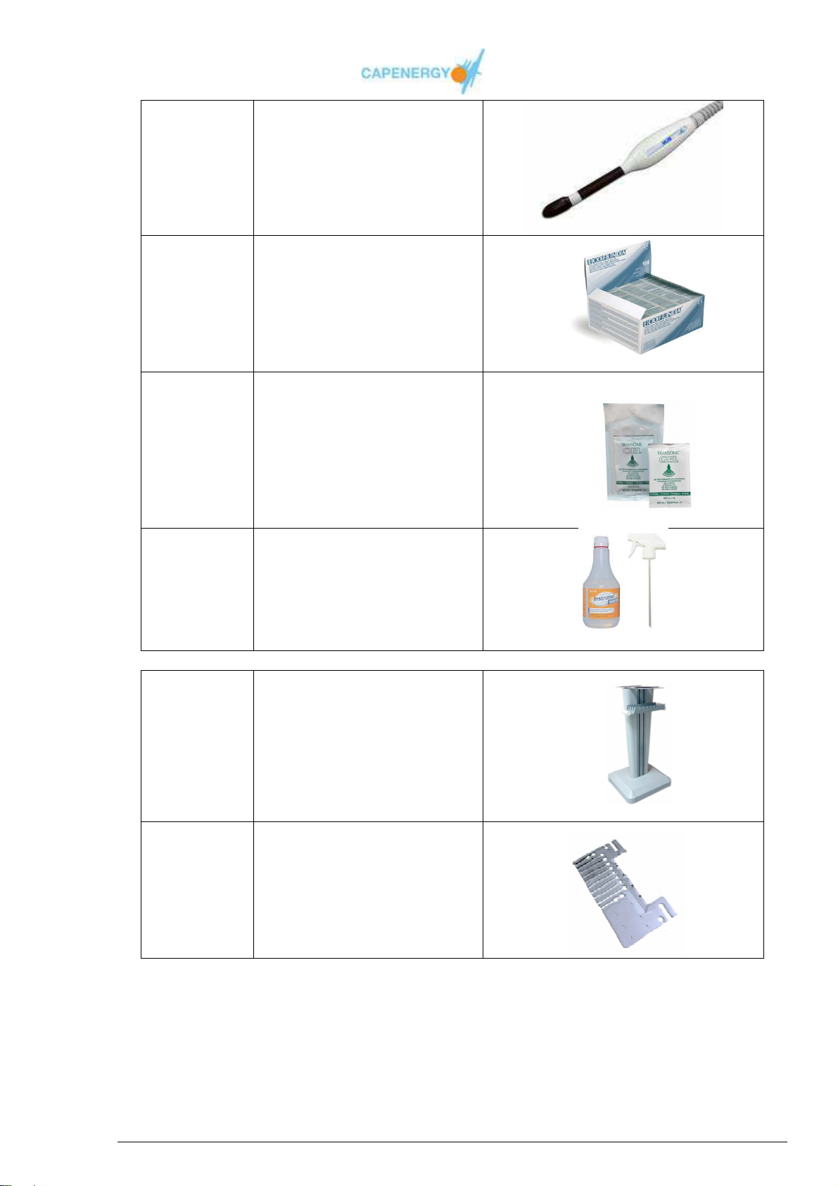
5350040 Intracavitary accessory MJS
Max. cable length 200 cm
5100135 Vaginal rectal probe
membranes for Intracavitary
accessory MJS
500 units per box
5100157 Gel for vaginal and rectal
use steril, in format of
unidose
Individual unit 20 ml
5310002
Product of Cleaning of
accessories, for Capenergy
devices.
5100040 Device base.
5100104 Accessory tray adaptable to
device base.
User Manual
Page 51 of 95
Page 52
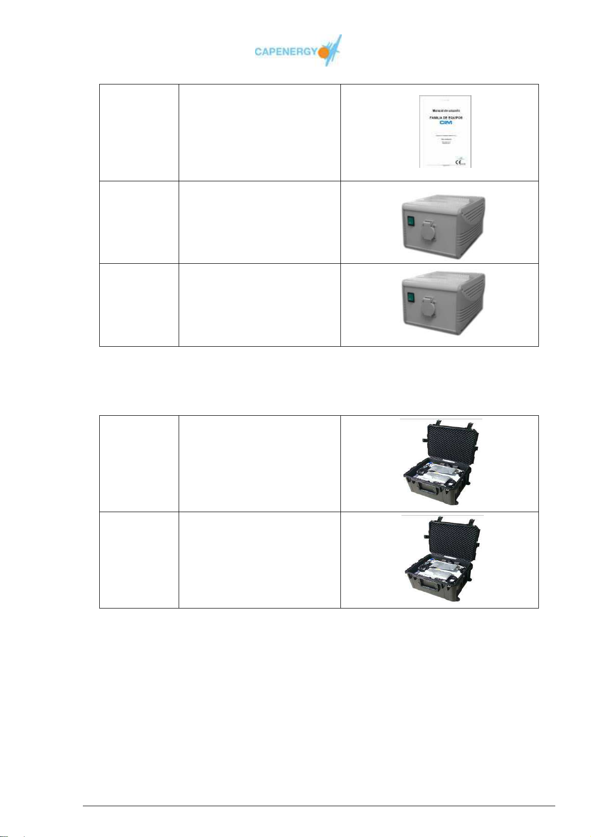
350200 User Manual CAPENERGY
DEVICES
5100147 Isolation transformer of
700VA
For C400 y C300
5100148 Isolation transformer of
450VA
For C50, C100, C200 and
C500
Table 6.1. Accessories of Diathermy Capenergy devices.
(OPTIONAL – NOT SUPPLIED WITH THE DEVICE)
5350002 Technical box to transport of
Capeneregy devices with
internal flocking.
Models C-50 to C-200
5350003 Technical box to transport of
Capeneregy devices with
internal flocking.
Models C-300 to C-400
Table 6.2. Solutions of movility to the transport of
Diathermy Capenergy devices.
User Manual
Page 52 of 95
Page 53

Chapter 7
Clinical application
In chapter 7, you will be explained how to perform treatments with the
CAPENERGY devices and how to apply the electrodes and plates in
function of the different pathologies.
CAPENERGY devices must be operated by qualified personnel and the
working methods and protocols described in this manual need to be
observed. In case of doubt we recommend you consult with the
manufacturer and / or medical advisor those symptoms not described in the
manual.
Warning
7.1 GETTING STARTED
What follows next forms part of basic knowledge and can be applied generally:
1. Take the device out of its packaging and verify no damages occurred during
transport. In case you detect any, do not use the device and notify of the damage as
described in the warranty conditions.
2. Before connecting the device to the network (230V~), make sure the power point has
been equipped with an earth wire.
3. Connect the mains cord to its corresponding connector in the back of the device and
insert the plug into the socket of the isolation transformer, then connect the isolation
transformer with his mains cord to the wall socket..
4. Start up the device by means of the switch located in the back of the device. As soon
as the device starts up, all the power outputs automatically set to ‘0’.
5. Before activating the device’s outputs connect the cable of the manual electrode to
the connector of the active output or connect the active plate to its corresponding
output. An electrode and an active plate cannot be connected at the same time to the
same connector.
6. Connect the cable of the passive plate to its corresponding connector.
7. Repeat the previous steps for all the electrodes or plates you wish to use during the
treatment.
User Manual
Page 53 of 95
Page 54

8. Before starting the treatment, apply the previously cleaned passive plate(s) to the
client’s skin. Apply a small amount of vehicle cream if necessary.
9. According to the type of treatment, apply a small amount of vehicle cream to the
manual electrode or the active automatic plate.
7.2 SECURITY AND MAINTENANCE WARNINGS
The following matters have already been commented upon in the Safety Chapter but
those related to the application will be further detailed hereafter:
General matters
The device must be connected to a power point that has been equipped with an earth
wire.
This device cannot be connected to other devices.
Always disconnect all the accessories that are not going to be used.
Do not use the device in the absence an operator who can assist the client.
The device’s casing must be cleaned using a damp cloth and very little neutral
detergent.
The environmental temperature cannot exceed the interval indicated in the user’s
manual in order to assure the correct functioning of the device. Using the device at a
temperature inferior or superior to the indicated interval, may affect the technical
reliability of the device.
In case that the patient has used any kind of adhesive bandage, it is important to
retire any rest of adhesive before the application of the plates.. Failure to comply with
this observance may cause burns.
Active plates / Passive plates
Always apply the plates with the power output set to zero
For reasons of hygiene, the active plates come with a washable cover. These covers
should be cleaned with water and soap after each treatment and they should be
replaced when they start to wear down. Complete cleaning after each treatment using
an class IIa disinfectant.
User Manual
Page 54 of 95
Page 55

Make sure the accessories and protective sleeves of the active plates are in a good
state. Worn down or damaged surfaces affect the functionality of the device and the
efficiency of the treatment and may cause damage to the device.
After each treatment, the active plates should be disinfected with a class IIa
disinfectant.
The passive plate must be placed in direct contact with the skin without using a
vehicle cream on the same surface. The active and passive plate should be
separated by at least 4 centimeters in order to avoid excessive temperature
increases.
All the plates that will be used during the treatment have to be applied to the patient
before activating the outputs. Only after applying all the plates, you may activate the
outputs. Do not under any circumstance invert the order of these procedures.
The plates should be handled by qualified personnel, with adequate knowledge of the
device and its use. Special attention should be paid to the positioning of the plates:
as much surface as possible should be in contact with the patient’s skin.
Apply always first the passive plate (metal) and only then the active plate (isolated).
After the treatment has come to an end, first remove the active plate and only then
the passive plate.
The power of each channel can be regulated independently from the others, by
pressing “” and “”. The power level of each output is indicated by its
corresponding led bar. Power output can be regulated when the outputs are
deactivated or activated.
When the cycle of the timer comes to an end and after a stop to deactivate the
outputs, the plates may be removed. First the active one and then the passive one.
The same procedure should be followed to move the plate or change their position on
the patient’s body.
When the device is used in automatic treatment mode (active and passive plates
applied to the patient’s body), the operator has to gradually increase the power until
the desired level has been reached. Only after verifying the patient’s level of
sensitivity and tolerance to the endogenous heat that is being produced and after
connecting the security control, the treatment can continue without the operator being
present. We nevertheless recommend you regularly check the patient’s tolerance and
heat sensitivity during the treatment.
When applying the fore-mentioned automatic treatments, the safety control must be
placed within the client’s reach.
The non-compliance of these safety norms may cause the passive plate (metal)
burning the patient’s skin when the device is functioning.
User Manual
Page 55 of 95
Page 56

The plates or non-insulated electrodes (resistive) cannot enter into contact with the
central unit’s casing or any other conductive material when the outputs of the device
are activated. This precaution will avoid other surfaces from being exposed to the
same power as the device’s output and thusly reduces the risk of electrocuting
patients and operators.
Manual electrodes
When manipulating electrodes during the treatment, always first set the power
regulator to zero.
After each treatment the manual electrodes should be disinfected with a class IIa
disinfectant..
Before cleaning the electrodes, the operator should turn off the device.
When using the manual electrode, make sure that:
- You have deactivated the outputs before applying the return element.
- The electrode is being used with as much contact surface as possible.
- When performing a resistive application, pay specific attention to the energy
being delivered by the device.
It is important to maintain the accessories with care. Please avoid them from bumping
or falling. Damaged accessories are a risk for the patient’s health and safety if applied
during a treatment.
During the application of the manual electrode, an excess of vehicle cream or
cosmetics may build up on the electrodes surface. This may generate a voltaic arc
causing the current to concentrate in that area and wearing down the electrode. In
case of a built-up it is therefore recommended you lower the power to cero and then
wipe off the excess product. You may then continue the treatment.
Intracavitary eletrode
Under no pretext should be used the intracavitary accessory with conductive gel
between the body of intracavitary and the vaginal-rectal probes. The use of the gel
should be exclusively external to the vaginal-rectal probes, when appropriate, as a
coupling medium.
The vaginal-rectal probes approved by the manufacturer is of prescriptive use for
performing intracavitary treatments, to ensure the health and safety, and to guarantee
the correct coupling, being prohibited the use of any other type of condom, echo
sounder, or similar product.
User Manual
Page 56 of 95
Page 57

Coupling creams
The coupling product serves to facilitate the electrical coupling and lubricate the
treated area to facilitate the displacement of the capacitive and resistive active
electrodes.
The recommended conductor product by the manufacturer to lubricate and facilitate
the movement of the electrodes is a emulsifier cream with moisturizing and emollient
properties, preferably free of parabens, with a proportional composition containing
natural oils, antioxidants extracts, and polar fatty factor.
You can neither use as a conductor product any cream whose composition
percentage is higher in water than oil, nor gels. You cannot either use any cosmetic
product which has been previously validated by the manufacturer
We do not recommend the use of products that contain cryogenic substances such
as menthol, camphor or similar. The same goes for carbon-based conductor gels: the
product base should by fat-soluble.. .
Do not use corrosive products such as glycolic acid.
You cannot use abrasive, thermogenic, cryogenic or anesthetic substances
You cannot use any substance which is identified to be aggressive for accesories,
due to the risk of electrode breakage.
7.3 POSSIBLE TREATMENT MODES
The multi-purpose design of the different CAPENERGY devices allows using different
combinations of manual electrodes and / or capacitive plates during one single
treatment.
In order to do so, you have to select the treatment you wish to perform:
I. Do you wish to work with one (1) automatic electrode (plate)
II. Do you wish to work with two (2) automatic electrodes (plates)
III. Do you wish to work with three (3) automatic electrodes (plates)
IV. Do you wish to work with four (4) automatic electrodes (plates)
V. Do you wish to work with one (1) insulated manual electrode (capacitive electrode
holder)
VI. Do you wish to work with one (1) automatic electrode (plate) and one (1) insulated
manual electrode (capacitive electrode holder)
User Manual
Page 57 of 95
Page 58

VII. Do you wish to work with two(2) automatic electrodes (plates) and one (1)
insulated manual electrode (capacitive electrode holder)
VIII. Do you wish to work with three (3) automatic electrodes (plates) and one (1)
insulated manual electrode (capacitive electrode holder)
IX. Do you wish to work with one (1) non-insulated manual electrode (resistive
electrode holder)
X. Do you wish to work with one (1) automatic electrode (plate) and one (1) non-
insulated manual electrode (resistive electrode holder)
XI. Do you wish to work with two (2) automatic electrodes (plates) and one (1) non-
insulated manual electrode (resistive electrode holder))
XII. Do you wish to work with three (3) automatic electrodes (plates) and one (1) non-
insulated manual electrode (resistive electrode holder)
XIII. Do you wish to work with one (1) insulated manual electrode (capacitive electrode
holder) and one(1) non-insulated manual electrode (resistive electrode holder)
Before pressing the start button located at the back of the device:
1) When using any type of manual electrode holder: place the electrode on
the skin surface of the area you are going to treat.
2) When using automatic active plates: place the active plates on the
treatment area and make sure the contact between the plate and the skin is
ideal by means of elastic bandages, If you are going to use the automatic
plates without an operator being present, connect the safety control holder
which allows the patient to stop the treatment at any time.
Place the passive plate(s) on the area(s) that will receive the return current.
Program the treatment time and press the START button.
Adjust the power until the client perceives the generated heat level as pleasant.
At the end of the treatment, an acoustic signal will be heard. Press the STOP button
and set the power regulator to 0.
Remove the plates.
Clean the plates and/or the manual electrodes used during the treatment.
User Manual
Page 58 of 95
Page 59
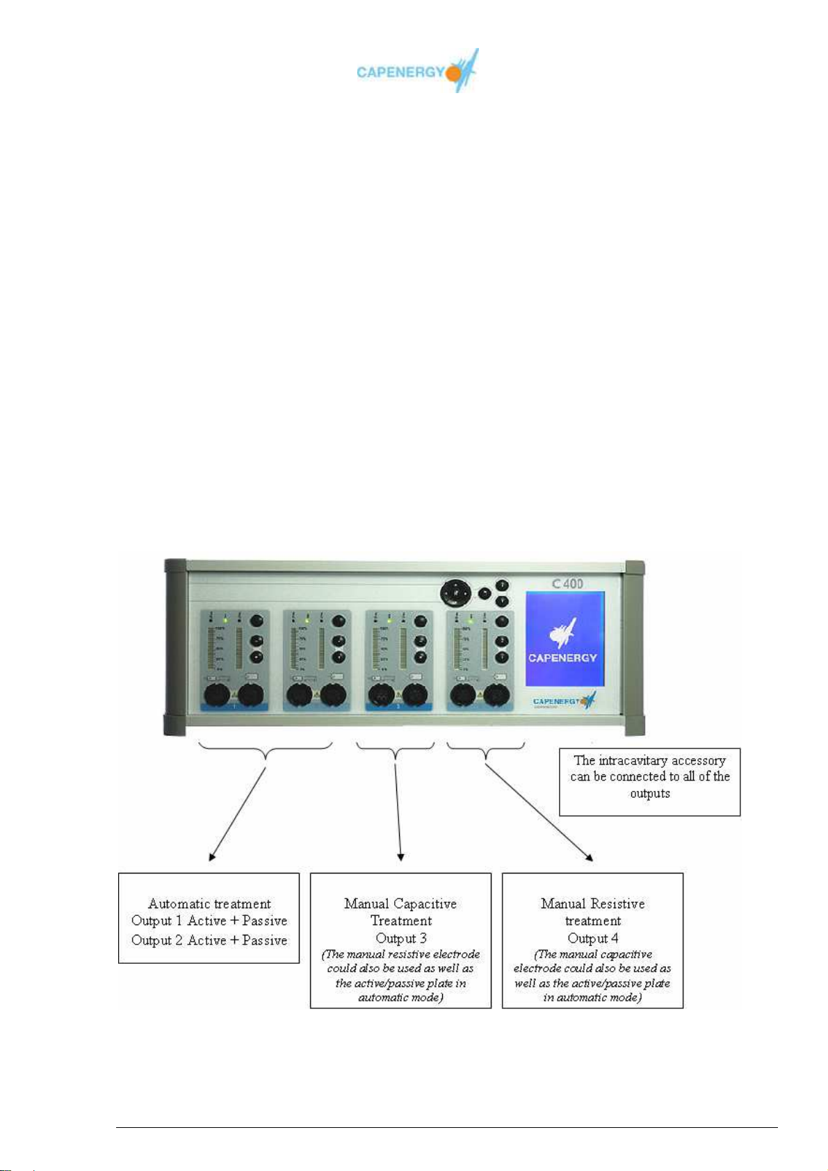
The C 400 allows working in all of the previously explained treatment modes, combining
manual and automatic techniques in one single session or working in automatic mode or
manual mode only. This means the operator can perform:
Automatic treatments with active / passive plates.
Manual treatments with an insulated (capacitive) electrode
Manual treatments with a non-insulated (resistive) electrode
Combined CAP-RES manual treatments
Combined manual and automatic treatments
The intelligent connectors recognize the accessories connected to each output which
allows the operator to easily adapt to its use and to display a great versatility.
The number of outputs is what makes this device into multi-purpose unit, enabling the
treatment of multiple pathologies or even multiple patients in one single session.
EXAMPLE OF A MULTIPLE COMBINATION (Automatic + manual treatment)
User Manual
Page 59 of 95
Page 60

MODUS OPERANDI AND USE (example) :
The patient will be lying on a couch in the supine or prone position, depending on the
treatment to be done. The operator will remain standing close to the area to be treated,
manipulating the corresponding accessory for each treatment and with easy access to
CAPENERGY device
As a general recommendation, before treating a patient and/or defining the treatment
protocol to follow, based on the pathology that has to be treated the operator should be
sure of how to approach the client’s pathology and what kind of treatment to apply:
Automatic treatment
Manual treatment with only 1 electrode
Manual treatment with 2 electrodes
Combined (automatic and manual)
The (patented) intelligent connect recognizes all different types of accessories and
identifies them on the screen, including the intracavitary accessory which can be
connected to all of the outputs.
1. Following the chosen approach, the operator will place the passive return plates on
the patient’s corresponding body areas, observing the following procedure:
Output 1 – Place the active plate on the treatment area and assure a perfect
contact between the plate and the skin by using the elastic bandages. When
using the automatic plate without the presence of an operator, the safety
control should be connected so the client can stop the treatment whenever he
wants to.
Output 2 – Repeat the previous procedure.
Output 3 – Place the active plate on the area that will receive the return
current and place the manual (capacitive or resistive) electrode on the
treatment area, making sure there is a perfect contact between the passive
plate and the skin and applying vehicle cream to more swiftly move the
electrode throughout the treatment.
Output 4 – Repeat the previous procedure.
2. The next step will be to determine the working mode::
Basic mode (power-driven)
Free treatment (power or temperature-driven)
Guided treatment (By indication / temperature-driven)
Through the menu options, the desired power can be selected (more information in
Chapter 4 – Indications for Use)
User Manual
Page 60 of 95
Page 61
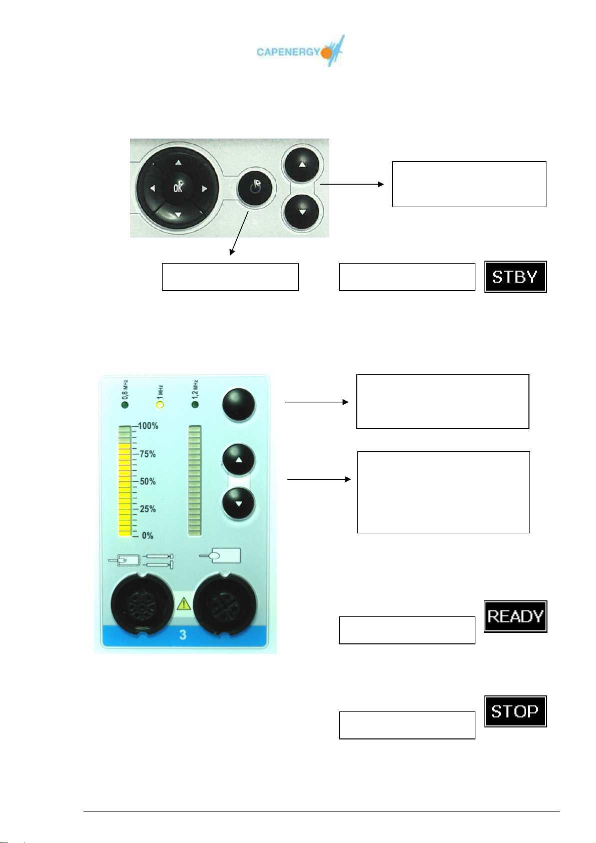
3. To start the treatment, push the START/STOP button, after establishing the
estimated treatment time.
Increase / Decrease of the
treatment duration
Start/stop button
Screen indicator
4. The power has to be regulated in such a way the client perceives the generated heat
as pleasant and the frequency adjusted according to the area or pathology to be
treated.
Frequency may vary throughout
the treatment.
Each Output is independent
The power has to be adapted
manually in such a way the
client perceives the generated
heat as pleasant.
Screen indicator
5. At the end of the treatment an acoustic signal will be heard and on the screen the
word STOP will appear:
Screen indicator
User Manual
Page 61 of 95
Page 62
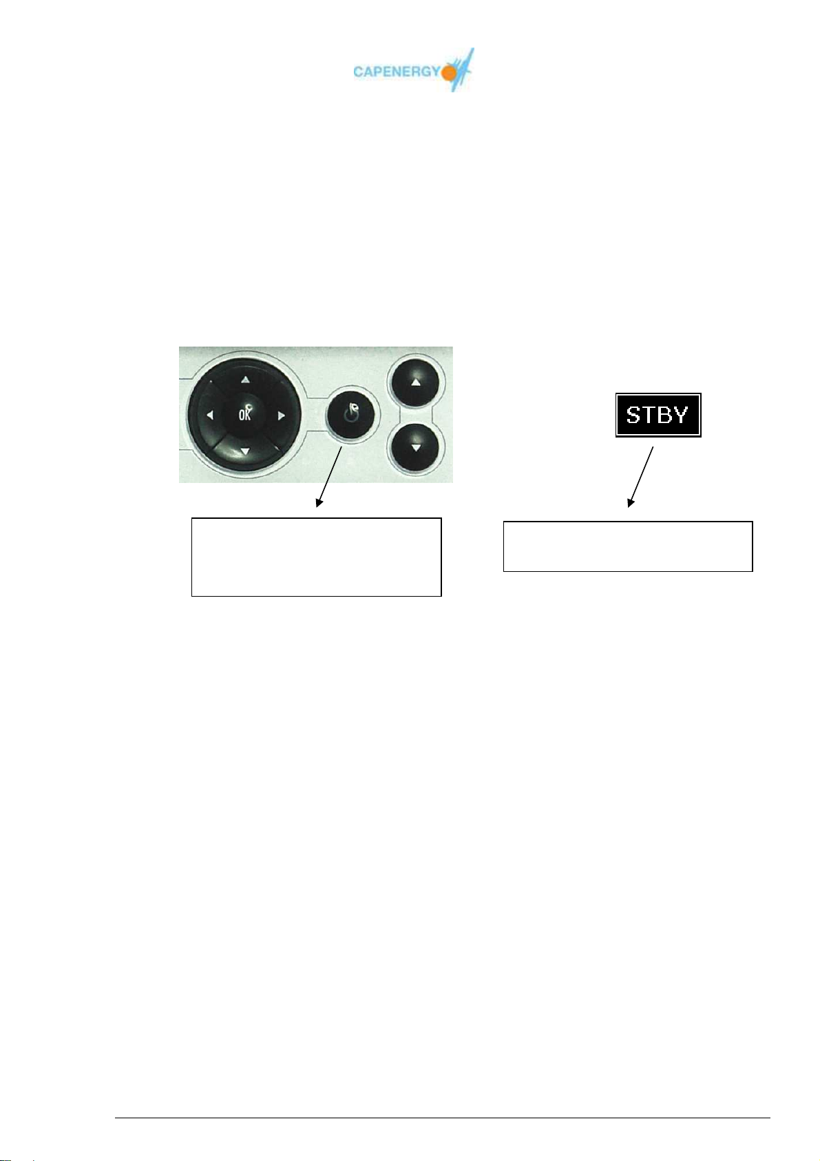
6. Once the treatment has come to an end, the passive plates will be removed (this
should only be done after the device has been turned off and without brusquely
pulling from the cables as this could damage the plates).
7. You can now proceed to cleaning the plates and/or manual electrodes used during
the treatment.
8. When accessories are changed in the course of a treatment, the device will turn down
automatically as a safety measure. Accessories should be changed with the device
on hold.
Press the start/stop button to
change accessories in the course
of a treatment
Screen indicating the device is on
hold.
User Manual
Page 62 of 95
Page 63

7.4 IMPORTANT PARAMETERS FOR USING CAPENERGY
a) Manual CAPACITIVE operating mode
Temperature
The sensation of heat generated inside the body depends of various factors and may
be perceived by the client as ranging from lukewarmness to intense endogenous
heat. The following should be taking into account when using manual capacitive
electrodes:
- Diameter of the electrode: At a same power, those electrodes with a larger
diameter will increase their temperature more gradually. Use them with the
protective hygienic membrane.
N.B.: It is correct to always choose the largest electrode available in function of
the area that needs to be treated as long as it correctly adapts to the skin’s
surface.
- Movement velocity: At a same power, the faster you move the electrode, lesser
will be the sensation of heath perceived by the patient.
N.B.: CAPENERGY devices can be used by applying a motionless electrode on
the treatment area or by applying the electrode in circular or linear movements,
according to the treatment surface and the power you wish to transmit.
Application pressure of the electrode
It is very important that the largest part of the electrode’s surface or the whole of it
remains in contact with the patient’s skin. This can be achieved by applying a discrete
pressure and following possible curvatures and irregularities of the treated areas,
continuously adapting to the latter. Correctly choosing the most adequate diameter
will be most helpful in this matter. A correct pressure is, without any doubt, important
to identify specific areas, core pain points or possible muscle contractions of the
middle superficial plane.
The electrode holder has been studied in detail in order to minimize the operator’s
efforts and to make the treatment more pleasant for the patient (deep tissue
massage, as if it were an extension of the operator’s hands.
N.B.: There are some exceptions where it is necessary to remain adhered to the skin
without exercising any specific pressure: this is the case with bruises, and phlebitis
and acute phlobosis in general.
User Manual
Page 63 of 95
Page 64

Type of tissue treated
The temperature perceived by the client in the manual capacitive mode depends
either on the parameters described before or on the type of the tissue located
immediately below the area where the electrodes are applied. The richer the deep
tissues are in liquids and electrolytes, the faster and the more marked the
temperature increase will be in equality of all the other parameters.
CAPENERGY devices is an instrument which, by means of a displacement current of
internal charges, can cause an increase of the endogenous temperature in function of
previously determined parameters. On the other hand, there are clinical situations
where it is not indicated to provoke such thermic increase. The analgesic, antiinflammatory and regenerative effect is present nevertheless, even when the internal
temperature is not increased.
b) Manual operating mode with direct coupling (RESISTIVE)
‘Direct coupling’ or RESISTIVE mode refers to the application of CIM with metal non
insulated electrodes (without an interposed dielectric). The activating mechanism of
this accessory, determined by the inversion of the current’s polarity, produces a faster
and more intense temperature increase in tissues that are not rich in water and
electrolytes (bone tissue and adipose tissue to be precise).
This application mode seems thus more indicated in combination with the capacitive
manual option for those pathologies that affect the fore-mentioned tissues.
Differences between the resistive and manual capacitive operating
mode
- DIRECTIONALITY: Given that the active electrode is not insulated, a smaller
concentration is produced in the area immediately below the active electrode that
takes on a directional aspect and is transported by the passive electrode (return
plate). Consequently, a displacement current of the charges is produced and a
temperature increase is generated inside the body. In other words, the main
difference resides in the special attention paid to the positioning of the return
electrode, which directs the impulses generated by the active electrode. For
example, when treating a lumbosciatic syndrome caused by a L-5 S-1 discopathy
with pain irradiation towards the heel, the return plate will be placed underneath
the foot, while the active plate will be applied in the lumbosacral area.
User Manual
Page 64 of 95
Page 65

- TEMPERATURE INCREASE: The power should be increased gradually from the
minimum up to the point where the patient notices a pleasant and bearable
temperature which can be perceived in the active or passive electrode or in both
at the same time, in function of the tissues located in between the two electrodes
and the penetrated diameter (at a same power, those areas with an smaller
diameter will heat up more, for instance, the wrist or the ankle). If the patient
during the treatment warns about an increase of the pain he feels, the power must
be lowered until this sensation disappears.
- MOUVEMENT: Differently from the capacitive mode, when using direct coupling
in most cases the electrode will be used in a fixed position or with subtle
movements in circles slightly larger than the diameter of the electrode that is being
used. The power has to be adjusted constantly to make sure the temperature
perceived by the client is pleasant at all times.
- ADHERENCE: It is important you always use electrodes that adhere perfectly to
the patient’s skin. Be careful not to touch the patient with the brim of the
electrode’s circumference.
IT IS IMPERATIVE TO AVOID THE RESISTIVE
ELECTRODE FROM ENTERING IN DIRECT
Warning
CONTACT WITH THE PASSIVE PLATE OF THE
WORKING DEVICE.
Direct contact will produce technical damages in the
device.
c)
Automatic operating mode with CAPACITIVE PLATE
Using the larger (200 cm2) capacitive automatic electrodes (active plates) offers
great advantages and allows to treat, without the need of an operator being
present, larger body areas. Each working channel (max. 4) works autonomously
and consists of a so called active plate and passive reception plate.
User Manual
Page 65 of 95
Page 66

Given the dimensions of the surface that can be treated, in spite of it being
insulated electrodes an ionic displacement current is generated capable of
creating a situation similar to that of the resistive operating mode.
In other words, as we’ve indicated before, in this case it also important to carefully
position the two electrodes in order to get the most out of the directionality of the
impulses created inside the organism.
The fundamental difference of the direct coupling consists in the careful evaluation
of the tissues located between the two electrodes: if the distance between them is
relevant and the tissues in between are mostly resistive, the electric field will
encounter obstacles that can interfere with the results. In that case it will be
necessary to reduce the distance between the active and passive electrode of the
same channel.
Let’s retake once more the example of the lumbosciatic syndrome L-5 S-1. If the
patient is overweight, the active plate has to be placed on the lumbosacral area
and the passive one along the nerve, for instance on the rear part of the thigh. If
the patient has a normal weight and even has a certain muscle tone (liquid rich
tissue), we can proceed in a way similar to direct coupling, placing the active plate
on the lumbosacral area and the passive plate against the foot sole.
The level of power applied should be assessed in function of the pathology that is
being treated and whether or not an increase of the internal temperature needs to
be obtained. The protocol will indicate the most appropriate parameters.
SUMMARY
1) Double working mode with operator
a. Capacitive mode
b. Direct coupling (resistive) mode
2) Operator free working mode (automatic)
a. Capacitive automatic plate with passive return plate.
3) Very versatile thanks to the fact that each channel can work autonomously and can
be used in all the treatment modes previously described.
User Manual
Page 66 of 95
Page 67

7.5 WORKING PROTOCOL FOR THE CAPENERGY DEVICES
Application with capacitive manual electrodes
The experience gathered by various operators (doctors and therapists) working on
thousands of patients all over the world, has allowed us to develop easy, secure and
efficient treatment protocols that deliver fast results.
APPLIED PARAMETERS
Position of the
electrode
Movement of the
electrode
Temperature: No matter what problem is being treated, the temperature
Application time The electrode should remain on each of the treatment
On those points indicated for the pathology that is being
treated
Fixed and slightly rotating, covering an area slightly larger
than the diameter of the electrode.
generated has to be bearable. The patient has to perceive
a pleasant sensation of lukewarmness.
points for 5 to 10 minutes, depending on the amount of
points considered and the total duration of the session.
There are no counter-indications so the operator may
prolong the treatment time of the considered areas as long
as he sees fit.
Position of the
passive electrode
It is best to always position the passive plate close to the
treated problem area.
SUMMARY
The ideal way to use CAPENERGY devices is combining manual/automatic modes. It is
particularly recommended to start the session by treating the trigger points during a
couple of minutes in manual capacitive mode and then continuing with the automatic
plates.
User Manual
Page 67 of 95
Page 68

7.6 CAPENERGY APPLICATION FREQUENCY
CAPENERGY devices can choose between three working frequencies, facilitating the
impedance matching between the equipment and the circuit formed between the
electrodes and the body. Available frequencies: 0.8 MHz, 1.0 MHz and 1.2 MHz
The column LED of therapy informs, in real time, about the power absorbed by the body,
helping the operator to select the optimal frequency that maximizes the power transfer.
When the column of LEDs of therapy achieves 100%, it indicates that it has reached the
possible maximum power transfer.
User Manual
Page 68 of 95
Page 69

7.7 THERAPEUTICAL TREATMENT APPLICATIONS
Pathologies of the muscles or articulations, fissures, orthopedics, physiotherapy
or sports medicine
- Non irradiated spine pathologies
- Lumbosacral spine with irridiations
- Lumbosciatic DX L1-L2
- Lumbosciatic DX L4-L5
- Knee pathologies
- Ankle and foot pathologies
- Cervical brachialgia
- Scapulohumeral Periarthritis
- Epicondilytis- epicondylitis
- Pathologies of the hand
Phlebological pathologies
Aesthetics Medicine and Surgery
Cystocele, cystitis, pelvic pain, etc…in uro-ginecology
Veterinary physiotherapy (under the supervision of a certified veterinarian)
Consult scientific publications, monographic therapeutic guides and documentation on
diathermy in medical treatments.
Feel free to ask us for further information, we will happily provide you.
User Manual
Page 69 of 95
Page 70
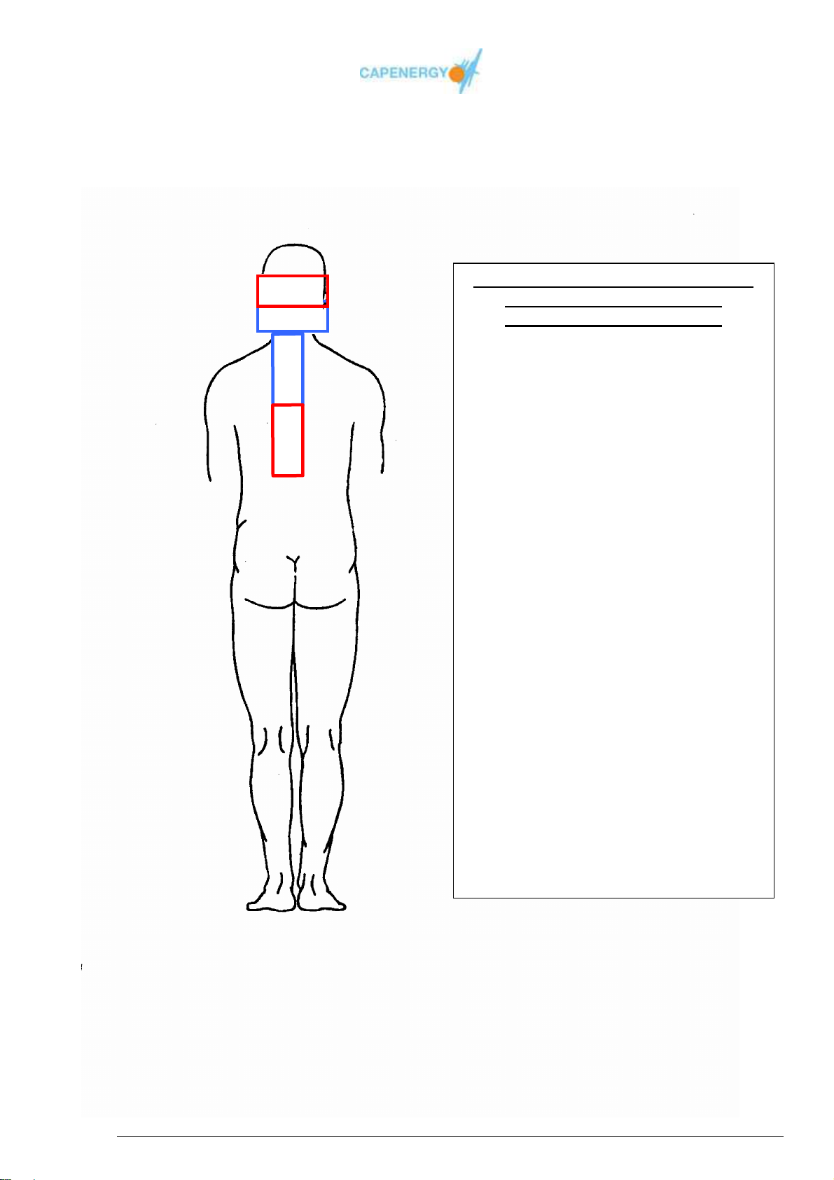
LEGEND:
AP
PP
=
RADIATED PATHOLOGIES
Nuchal Cefalea
–
Lumbalgias
Application time:
Sensation perceived by the patient:
Lower the potency when the patient
N.B: CIM vehicles products. We advise
-
-
alopathics
(essential oils, fytotherapeuticals,
oxicologicals) to apply on the cleand
-
free skin before performing the
treatment.
EXAMPLES OF APPLICATIONS: PHYSIOTHERAPY
AP1
PP2
PP1
AP2
APPLICATION SCHEME FOR NON
-
SITUATED IN THE RAQUIS
Cervical artrosis
Cervical spinal distorsion
Dorsalgias
-
Hieralgias
Treatment mode
Nº applications: from 3 to 10
20 minuts
Advised potency: low/average
non intense warmth
Re gulation during therapy:
reports an excessive temperature.
using miorelaxing products and/or anti
inflammatory alopathics or non
homot
and grease
=
Active Plate
Passive Plate
User Manual
Page 70 of 95
Page 71
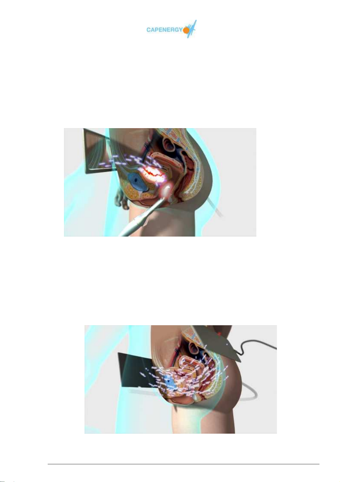
EXAMPLES OF APPLICATIONS URO-GYNECOLOGY
(Cystocele, cystitis, annal fissures, pelvic pain, etc, ..)
ON A WOMAN
INTRACAVITARY ELECTRODE POINTING FORWARDS AND PLATE ON THE
ABDOMEN
Intracavitary application:
Intracavitary accessory pointing forwards. Return plate on the abdomen..
Extracavitary application:
The same application can be done with plates in automatic mode: active plate on the
sacro and return passive plate on the abdomen.
User Manual
Page 71 of 95
Page 72
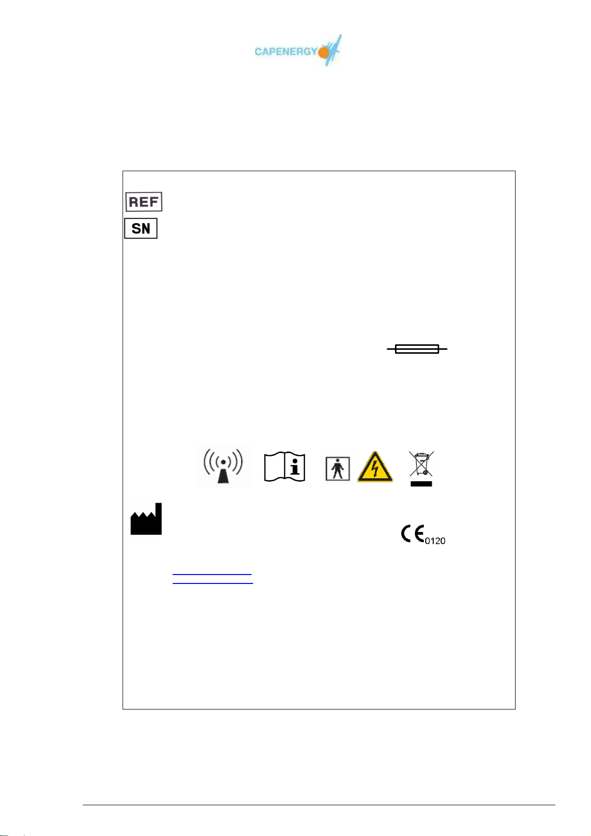
IDENTIFICATION OF THE MARKINGS
C XXX
533XXXX Identification of the reference of the device
20XX-00X-00XX Identification of the serial number of the
230V~ / 50Hz / 800 W
Electrical specifications
Class I BF
Electrical classification of the device
Capenergy Medical S.L
Av. Mare de Deu de Montserrat,41
Pasaje 1º derecha
08970 Sant Joan Despí
Barcelona – España
MADE IN SPAIN
(*) Consult table with model specifications. The 800W power output corresponds to a C 400 model.
Identification of the model of the device
generated by WINGEST
device composed of :
Production date
Production order
Number of the produced unit
This number allows tracking sold devices
as well as their identification
(*)
Applicable symbols
2x 5x20mm 250V~ T3,15 A
Fuses
EN 60601-1
Applicable regulation
Identifier of the CE marking and
number of the notified body
REV: 2014-12-B
Label design review, composed of::
• Year of approval of the label
design
• Month of approval of the label
design
• Applicable version
Appendix A
User Manual
Page 72 of 95
Page 73
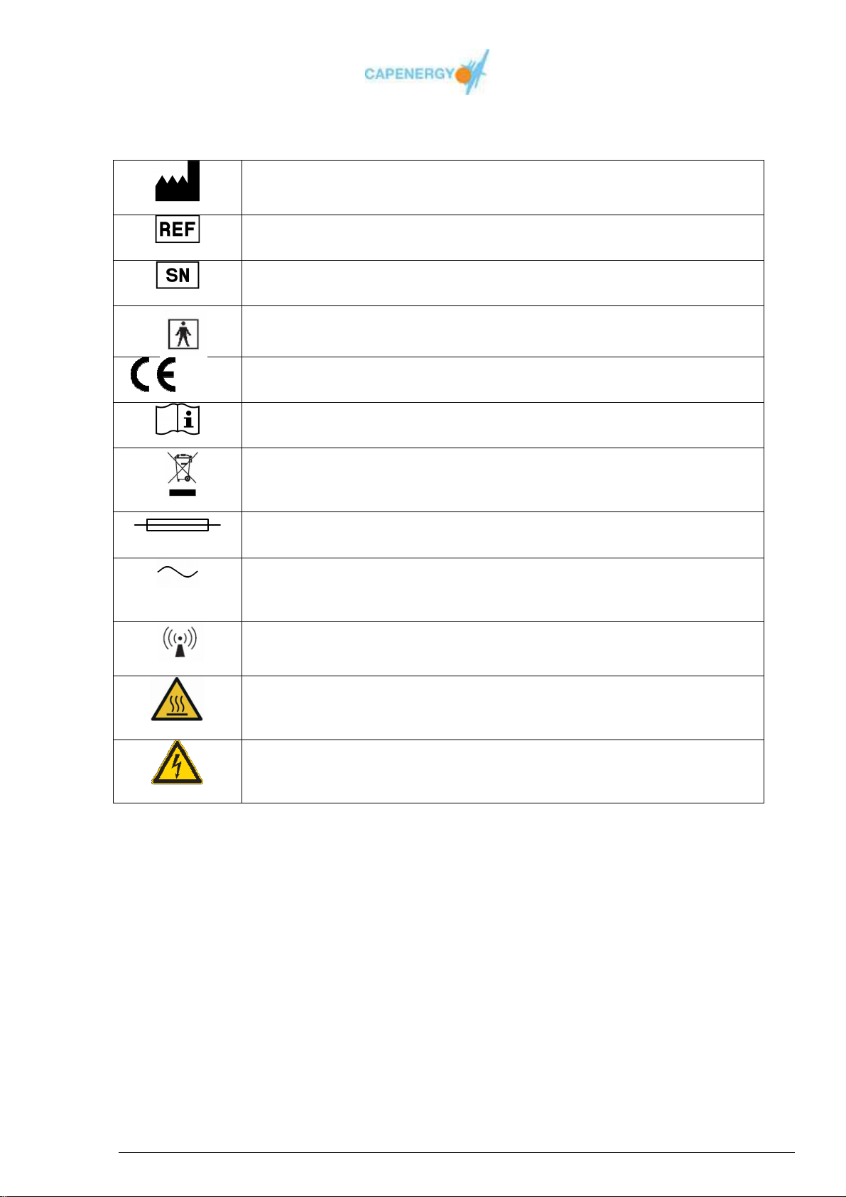
MEANING OF THE SYMBOLS
Symbol representing the MANUFACTURER. This symbol is accompanied by
XXXX
the name and address of the manufacturer
Symbol representing the reference of the product according to the
CATALOGUE
Symbol representing the SERIAL NUMBER
Symbol representing the BF TYPE
CE symbol with the intervention of a Notified Body
Symbol for CONSULT INSTRUCTIONS FOR USE
RAEE symbol
FUSE symbol
Symbol for ALTERNATING CURRENT
Symbol for MEDICAL DEVICE THAT APPLIES ELECTROMAGNETIC RF
ENERGY FOR TREATMENT OR DIAGNOSE
Symbol for HOT SURFACE WARNING
Symbol for HAZARDOUS VOLTAGE
User Manual
Page 73 of 95
Page 74

Appendix B
CERTIFICATE OF DELIVERY AND INSTALLATION
User Manual
Page 74 of 95
Page 75

CERTIFICATE OF DELIVERY AND INSTALLATION
The undersigned _______________________________________, has been qualified and
entitled to act in name and respresentation of the company Capenergy Medical, S.L, with VAT B62171731, and central offices in Sant Joan Despí (Barcelona), Avda. Mare de Déu de
Montserrat, 41, for the emission of the certificate of installation for the following device:
Model ________________ Serial number __________ Date of production ___________
And DECLARES
Having verified all standard accessories and they are in a correct state.
Having installed the device according to the manufacturer’s instructions.
Having received the user manual in the ________________ language.
Having instructed all personnel responsible for using the device.
Having verified the total absence of defects and the correct functioning of the device.
Having verified the correct functionality of the safety control.
Having verified that the user does not have any reservation or objection regarding the
delivered good and that he therefore accepts it unconditionally.
The operations have been performed in presence of ____________________________,
employee selected by medical center______________________located in
_______________________________ at the following address
______________________________________________Email: ____________________
as the person responsible for the use of the device.
The present declaration is issued for the agreed upon use and according to the approved laws.
Date,___ of ____________,
The installation
tecnic
.........................................
1 Three (3) copies of this certificate are issued:one for the client, one for the distributor and a third one has to be filled in and sent
to the manufacturer CAPENERGY MÉDICAL,S.L. within 7 days after the installation of the device.
............................
The client
Stamp and signature
.........................
REG.7.2-01-01
User Manual
Page 75 of 95
Page 76
CLINICAL CASUISTRY DOCUMENT
CLINICAL CASUISTRY
Management document
DETAILS FOR IDENTIFICATION OF THE STUDY
Contact person
Trade name
(Fiscal) Identification nº
Address / City
Appendix C
Telephone E-mail
Model
Serial number
TITLE OF THE STUDY / INVESTIGATION
Starting date End date
INTRODUCTION
ANAMNESIS
User Manual
Page 76 of 95
Page 77

MATERIAL AND METHOD
1. City :
2. Criteria for inclusion :
3. Criteria for exclusion
4. Control Group : SI NO
TREATMENT PROTOCOLE
RESULTS
User Manual
Page 77 of 95
Page 78
SIDE EFFECTS ASSOCIATED WITH THE TREATMENT
Skin irritation Others :
Curative crisis Others :
Burns Others:
DISCUSSION / CONCLUSIONS
OTHER COMMENTS / COMPLEMENTARY CONTRIBUTIONS:
ISSUED DOCUMENTS (in attachment)
Informed consent
Ultrasound scan, X-ray
CD archive / electronic format
User Manual
Page 78 of 95
Patient Evaluation File
Lab examinations
Others
Page 79
BIBLIOGRAPHY
Confirmation of sending by the
professional
Confirmation of reception by Capenergy
Medical
Date / Stamp / Signature
Date / Stamp / Signature
Associated Nº Nº of Study
Send by e-mail to [email protected] or by Fax : +34 (93) 477.42.90
This fac-simile has to be filled out and sent to:
CAPENERGY MEDICAL, SL
Avda. Mare de Deu de Montserrat, 41 - Pasaje 1º Derecha
08970 Sant Joan Despí (Barcelona) - España
Tel.: + 34 (93) 477.43.48 / Fax: + 34 (93) 568 752
[email protected]
You may also take a picture of the filled out form with your Smartphone and send it by Whatsapp
+34 605 94 85 73.
In order to contribute to the recollection of clinical data necessary for the permanent scientific
validation of the device, CAPENERGY MEDICAL, SL has the authorization to use the received
information, treating sensitive data with due respect and observing the established privacy
norms.
In case CAPENERGY MEDICAL, SL considers it convenient to reveal and/or publish these data,
it is hereby authorized to do so.
Ref : Sistema ISO 13485 - REG.7.3-03-03
User Manual
Page 79 of 95
Page 80

Appendix D
NOTIFICATION OF BREAKDOWN
User Manual
Page 80 of 95
Page 81
NOTIFICATION OF BREAKDOWN
BY THE CLIENT
DETAILS FOR IDENTIFICATION
Contact person
Trade name
(Fiscal) Identification nº
Address / City
Telephone
Model
Date of purchase Sold by
DETECTED BREAKDOWN or ANOMALY
E-mail
Serial number
Shipment confirmation Confirmation of reception
Date / Stamp / Signature
TAS ID nº
Send by e-mail to [email protected] or by Fax : +34 (93) 477.42.90
User Manual
Page 81 of 95
Date / Stamp / Signature
Page 82

Appendix E
Warnings concerning Logistics and Transport
The following warnings should be taken into consideration when receiving a
CAPENERGY device in order to be able to activate the legal warranty and / or proceed
to lodge the corresponding complaint to the transport agency in case the device has
suffered damages during its shipment:
1. Upon reception of the CAPENERGY device please check if the package received is
in perfect state. If not, please contact the provider / transport agency by telephone or
by writing in order to lodge the corresponding complaint. This has to be done within
48 hours after the reception. The same procedure should be observed when installing
HOW TO ACTIVATE THE WARRANTY
the device.
2. When receiving the shipment, please write the following on the delivery note: ‘Goods
received, pending inspection’, to make sure you have time to check the entire device
during its installation.
3. Within 7 working days after the reception of the device, it is mandatory to send the
manufacturer a copy of the ‘Certificate of Installation and Delivery’, in order to activate
the legal warranty.
4. If the manufacturer does not receive copy of the ‘Certificate of Installation and
Reception’, any intervention of the technical service will be charged to the client.
5. The original ‘Certificate of Installation and Delivery’ (not a copy) has to be signed and
sent to the following address:
CAPENERGY MEDICAL, SL
Avda. Mare de Deu de Montserrat, 41 - Pasaje 1º Derecha
08970 Sant Joan Despí (Barcelona) - España
6. In case technical assistance under warranty is required, before shipping the device to
the manufacturer, please carefully read the indications and prescription on how to do
this. UNDER NO CIRCUMSTANCES WILL THE MANUFACTURER ACCEPT
DEVICES THAT DO NOT INCLUDE THE CORRESPONDING ACCESSORIES
(electrodes, active and passive plates, etc… as corresponding to the CAPENERGY
model at hand)
7. The ‘Breakdown Notification’ form should be sent along with the device and the
accessories to identify the device. Make a photocopy of the corresponding appendix
of this User manual, fill it in by hand and sign it, in order to proceed to the repair of
the device.
8. In case you send the device through a transport agency, please pack the device with
care (we recommend you keep the original wooden box) and send it sealed on a
pallet exclusively. The device travels at the client’s risk and expenses. Make sure the
sender’s details are clearly identified as well as the destination. Once you’ve signed
the pickup note, please send a copy of it to us by email so we can track the parcel
and make sure it does not get lost or delayed.
User Manual
Page 82 of 95
Page 83

Appendix F
REGARDING ELECTROMAGNETIC
COMPATIBILITY (CEM)
The equipments of the CAPENERGY product range: C400, C300, C200, C100, C50 and
C500, require special precautions regarding CEM and need to be installed an used
according to the CEM information provided in this user manual.
Guidance and manufacturer’s declaration – electromagnetic emissions
The equipments of the CAPENERGY product range: C400, C300, C200, C100, C50 and C500 are
intended for use in the electromagnetic environment specified below. The customer or the user the
CAPENERGY product range: C400, C300, C200, C100, C50 and C500 should assure that it is used
in such an environment.
Emissions test Compliance Electromagnetic environment - guidance
RF emissions
CISPR 11
RF emissions
CISPR 11
Harmonic emission
IEC 61000-3-2
Voltage fluctuations/ flickers
emissions
IEC 61000-3-3
Table J-1. Electromagnetic emissions
GROUP 2 The equipments of the CAPENERGY product
range : C400, C300, C200, C100, C50 and
C500 must emit electromagnetic energy in order
to perform its intended function. Nearby
electronic equipment may be affected..
Class A
Class A
Complies
The equipments of the CAPENERGY product
range : C400, C300, C200, C100, C50 and
C500 is suitable for use in all establishments
other than domestic, and may be used in
domestic establishments and those directly
connected to the public low-voltage power
supply network that supplies buildings used for
domestic purposes, provided the following
warning is heeded:
Warning: This equipment/system is intended
for use by healthcare professionals only. This
equipment/ system may cause radio
interference or may disrupt the operation of
nearby equipment. It such as re-orienting or
relocating the equipments of the
CAPENERGY product range : C400, C300,
C200, C100, C50 and C500 or shielding the
location.
User Manual
Page 83 of 95
Page 84

Guidance and manufacturer’s declaration – electromagnetic immunity
The equipments of the CAPENERGY product range: C400, C300, C200, C100, C50 and C500 are
intended for use in the electromagnetic environment specified below. The customer or the user of the
equipments of the CAPENERGY product range: C400, C300, C200, C100, C50 and C500 should
assure that it is used in such an environment.
Immunity test IEC 60601
test level
Electrostatic discharge
(ESD)
IEC 61000-4-2
Electrical fast
transient/burst
IEC 61000-4-4
Surge
IEC 61000-4-5
Voltage dips, short
interruptions and voltage
variations on power
supply input-lines
IEC 61000-4-11
Power frequency
(50/60 Hz)
Magnetic field
IEC 61000-4-8
NOTE: UT is the a.c. mains voltage prior to application of the test level.
±6 kV contact
±8 kV air
±2 kV for power
supply lines
±1 kV for input/output
lines
±1 kV line(s) to
line(s)
±2 kV line(s) to earth
<5% UT
(>95% dip in UT )
for 0,5 cycle
40% UT
(60% dip in UT )
for 5 cycles
70% UT
(30% dip in UT )
for 25 cycles
<5% UT
(>95% dip in UT )
for 5 s
3 A/m 3 A/m Power frequency magnetic
Compliance level Electromagnetic
environment - guidance
±6 kV contact
±8 kV air
±2 kV for power
supply lines
±1 kV for power
inputs/outputs
±1 kV line to line
±2 kV line to earth
<5% UT
(>95% dip in UT )
for 0,5 cycle
40% UT
(60% dip in UT )
for 5 cycles
70% UT
(30% dip in UT )
for 25 cycles
<5% UT
(>95% dip in UT )
for 5 s
Floors should be wood,
concrete or ceramic tile. If
floors are covered with
synthetic material, the
relative humidity should be
at least 30%
Mains power quality should
be that of a typical
commercial or hospital
environment.
Mains power quality should
be that of a typical
commercial or hospital
environment.
Mains power quality should
be that of a typical
commercial or hospital
environment. If the user of
the equipments of the
CAPENERGY product
range: C400, C300, C200,
C100, C50 and C500
requires continued
operation during power
mains interruptions, it is
recommended that the
equipments of the
CAPENERGY product
range: C400, C300, C200,
C100, C50 and C500 be
powered from an
uninterruptible power supply
or battery
fields should be at levels
characteristic of a typical
location in a typical
commercial or hospital
environment.
Table J-2. Electromagnetic immunity
User Manual
Page 84 of 95
Page 85
Guidance and manufacturer’s declaration – electromagnetic immunity
The equipments of the CAPENERGY product range: C400, C300, C200, C100, C50 and C500 are intended for
use in the electromagnetic environment specified below. The customer or the user of the equipments of the
CAPENERGY product range: C400, C300, C200, C100, C50 and C500 should assure that it is used in such an
enviroment.
Immunity test IEC 60601 test
level
Conducted RF
IEC 61000-4-6
Radiated RF
IEC 61000-4-3
3 Vrms
of 150 kHz to 80 MHz
3 V/m
of 80 MHz to 2,5 GHz
Compliance
level
3 V
3 V/m
The laboratory
limit is 1GHz
Electromagnetic environment guidance
Portable and mobile RF communications
equipment should be used no closer to
any part of the equipments of the
CAPENERGY product range: C400,
C300, C200, C100, C50 and C500,
including cables, than the recommended
separation distance calculated from the
equation applicable to the frequency of
the transmitter
Recommended separation distance
d=1.2
d= 1.2
d=2.3
where P is the maximum output power
rating of the transmitter in watts (W)
according to the transmitter
manufacturer and d is the recommended
separation distance in meters (m).
Field strengths from fixed RF
transmitters, as determined by an
electromagnetic site survey, should be
less than the compliance level in each
frequency range.
Interference may occur in the vicinity of
equipment marked with the following
symbol:
P
P
80 MHz to 800 MHz
P
800 MHz to 2,5 GHz
NOTE 1 At 80 MHz and 800 MHz, the highest frequency range applies
NOTE2 These guidelines may not apply in all situations. Electromagnetic propagation is affected by absorption
and reflection from structures, objects and people.
a
Field strengths from fixed transmitters, such as base stations for radio (cellular / cordless) telephones
and land mobile radios, amateur radio, AMF and FM radio broadcast and TV broadcast cannot be
predicted theoretically with accuracy. To assess the electromagnetic environment due to fixed RF
transmitters, an electromagnetic site survey should be considered. If the measured field strength in the
location in which equipments of the CAPENERGY product range: C400, C300, C200, C100, C50 and
C500 are used exceeds the applicable RF compliance level above, the equipments of the CAPENERGY
product range: C400, C300, C200, C100, C50 and C500 should be observed to verify normal operation.
If abnormal performance is observed, additional measures may be necessary, such as re-orienting or
b
relocating the equipments of the CAPENERGY product range: C400, C300, C200, C100, C50 and C500.
Over the frequency range 150 kHz to 80 MHz, field strength should be less than 3V/m.
Table J-3. Electromagnetic immunity. Radiated emissions.
User Manual
Page 85 of 95
Page 86
Following the results of the radiated immunity tests, if the device suffers radiated
electromagnetic disturbance, the normal functioning can be interrupted and a nonauthorized accessory change alarm will be displayed. In this case, the user only needs to
deactivate the alarm by pressing the OK button, make sure the electromagnetic
disturbance has disappeared and resume the treatment by selecting the corresponding
treatment parameters.
Recommend separation distances between
portable and mobile RF communication and the equipment and the equipments of the
CAPENERGY product range: C400, C300, C200, C100, C50 and C500.
Rated maximum
output power
transmitter
W
0,01 0,12 0,12 0,23
0,1 0,38 0,38 0,73
1 1,2 1,2 2,3
10 3,8 3,8 7,3
100 12 12 23
For transmitters rated at a maximum output power not listed above, the recommended separation
distance d in meters (m) can be estimated using the equation applicable to the frequency of the
transmitter, where P is the maximum output power rating of the transmitter in watts (W) according to
the transmitter manufacturer.
NOTE 1 At 80 MHz and 800 MHz, the separation distance for the higher frequency range
applies.
NOTE 2 These guidelines may not apply in all situations. Electromagnetic propagation is
affected by absorption and reflection from structures, objects and persons.
Separation distance according to frequency of transmitter
m
150 kHz to 80 MHz
d=1,2
P
80 MHz to 800 MHz
d=1,2
P
800 MHz to 2,5 GHz
d=2,3
P
Table J-4
and the equipments of the CAPENERGY product range: C400, C300, C200, C100, C50 and C500.
Recommend separation distances between portable and mobile RF communication equipment
User Manual
Page 86 of 95
Page 87

Apéndice G
CAPENERGY EQUIPMENT FAMILY
The CIM equipment range consist of 6 different models. In the following section you will
find the characteristics and equipment of each of the different models.
User Manual
Page 87 of 95
Page 88
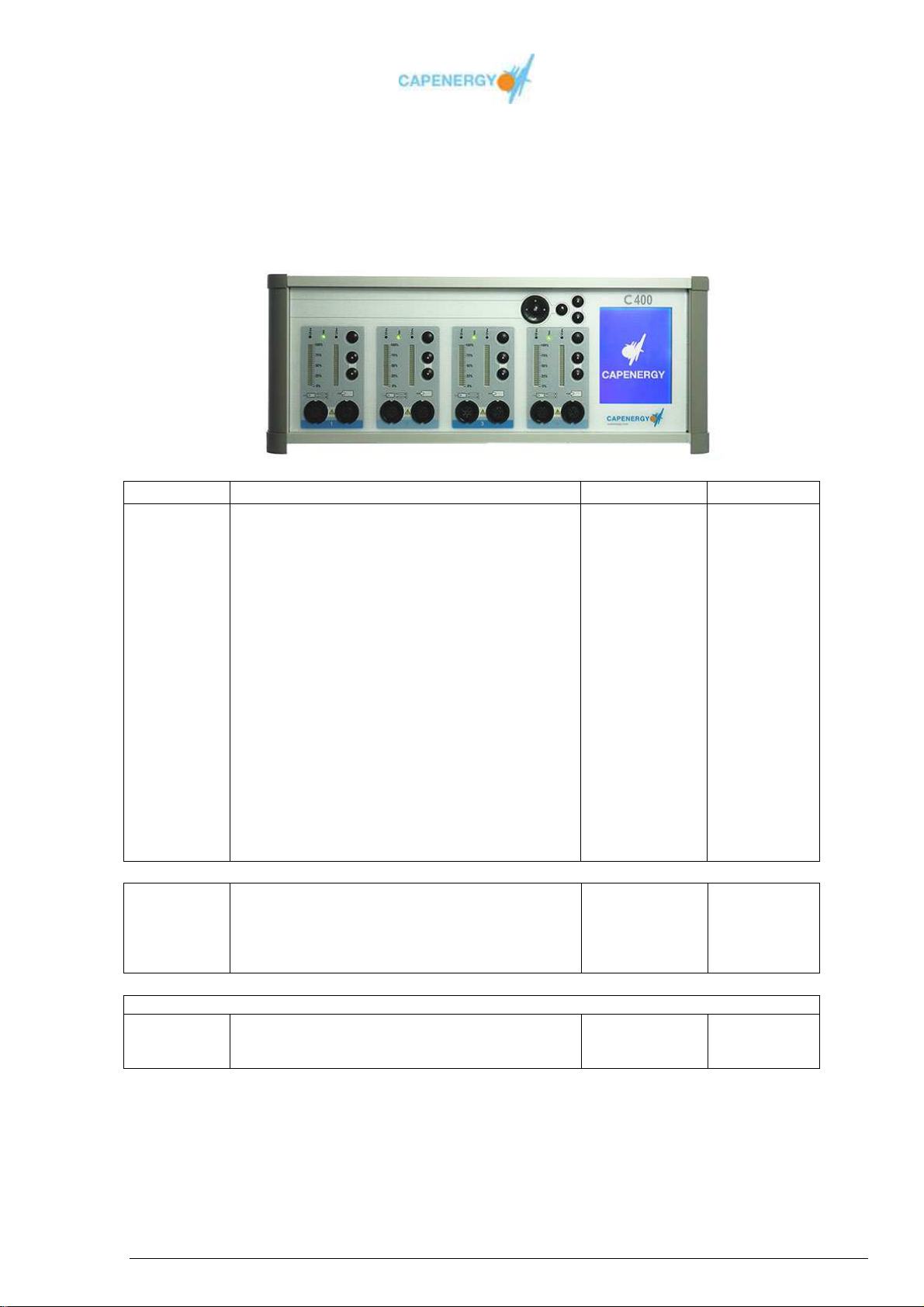
C 400
Ref 5330004
Device with 4 work channels: automatic and manual for individual or simultaneous use of
capacitive and/or resistive electrodes.
Units Description Ref Equipment
1 Device C 400 5330004 Standard
1 User Manual 350200 Standard
2 Mains cord 080224 Standard
1 Safety control 5350070 Standard
4 Active plates with temperatura sensor 5350037 Standard
4 Passive plates 5350038 Standard
4 Hygienic protective gel covers 5100013 Standard
4 Hygienic protective covers without gel 5100060 Standard
1 Straight resistive electrode holder 5350033 Standard
1 Straight capacitive electrode holder 5350034 Standard
1 Capacitive electrode 33 mm 5100025 Standard
1 Capacitive electrode 53 mm 5100027 Standard
1 Capacitive electrode 65 mm 5100028 Standard
1 Resistive electrode 33 mm 5100029 Standard
1 Resistive electrode 53 mm 5100031 Standard
1 Resistive electrode 65 mm 5100032 Standard
8 Elastic bandage 80 cm 5100028 Standard
8 Elastic bandage 60 cm 5100030 Standard
8 Elastic bandage 40 cm 5100029 Standard
1 Isolation transformer of 700VA 5100147 Standard
1 90º capacitive electrode holder 5350035 Optional
1 90º resistive electrode holder 5350036 Optional
1 Capacitive electrode 65 mm 5100028 Optional
1 Resistive electrode 65 mm 5100032 Optional
4 Active plates WITHOUT temperature sensor 5350039 Optional
UPGRADE TO C 500 : YES
1 Intracavitary accessory MJS 5350040 Upgrade
1 Box vaginal/rectal probe covers intracavitary
accessory MJS (144 unids x caja)
5100131 Upgrade
User Manual
Page 88 of 95
Page 89
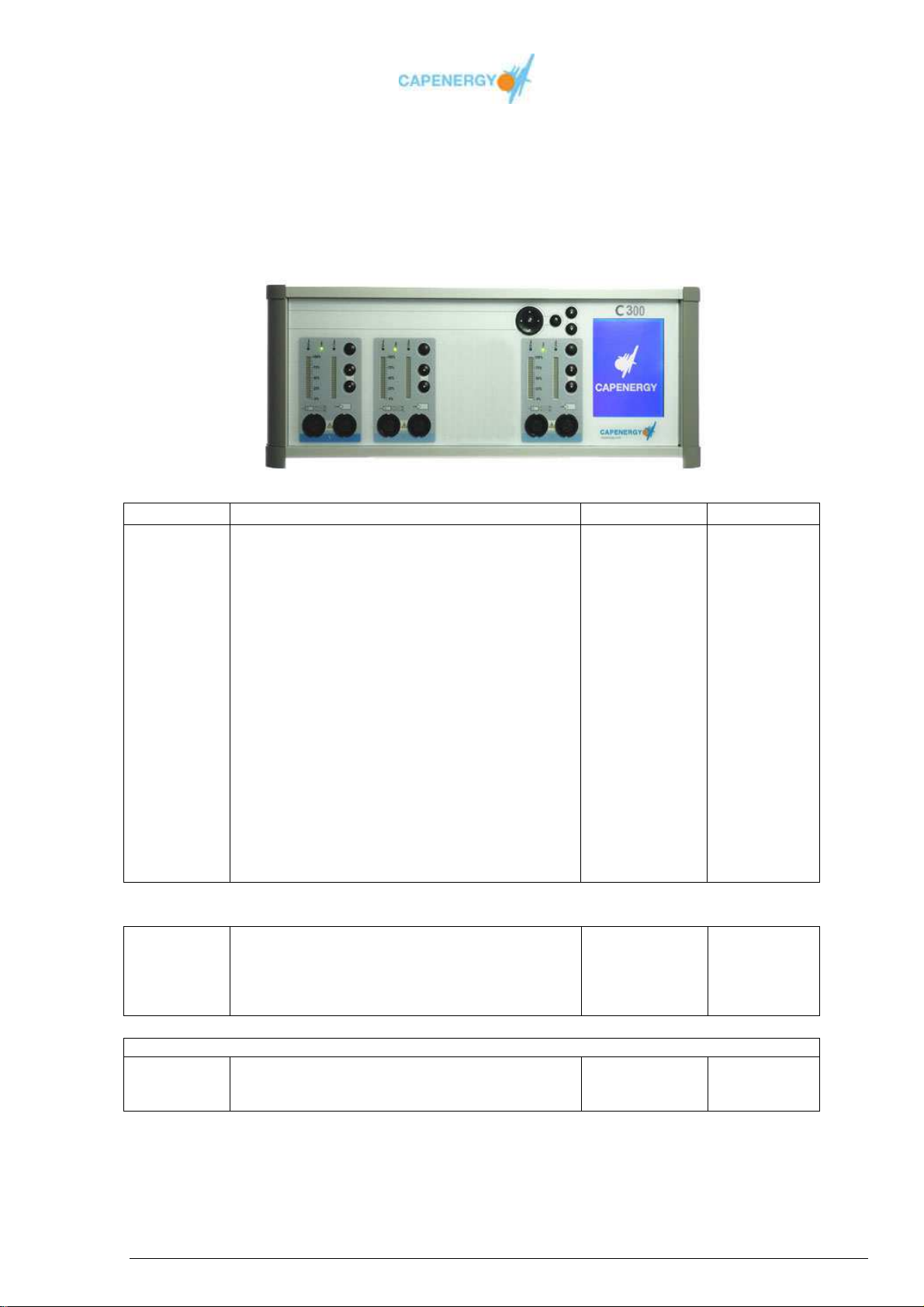
C 300
Ref 5330003
Device with 3 work channels: automatic and manual for individual or simultaneous use of
capacitive and/or resistive electrodes
Units Description Ref Equipment
1 Device C 300 5330003 Standard
1 User Manual 350200 Standard
2 Mains cord 080224 Standard
1 Safety control 5350070 Standard
3 Active plates with temperature sensor 5350037 Standard
3 Passive plates 5350038 Standard
3 Hygienic protective gel covers 5100013 Standard
3 Hygienic protective covers without gel 5100060 Standard
1 Straight resistive electrode holder 5350033 Standard
1 Straight capacitive electrode holder 5350034 Standard
1 Capacitive electrode 33 mm 5100025 Standard
1 Capacitive electrode 53 mm 5100027 Standard
1 Capacitive electrode 65 mm 5100028 Standard
1 Resistive electrode 33 mm 5100029 Standard
1 Resistive electrode 53 mm 5100031 Standard
1 Resistive electrode 65 mm 5100032 Standard
6 Elastic bandage 80 cm 5100028 Standard
6 Elastic bandage 60 cm 5100030 Standard
6 Elastic bandage 40 cm 5100029 Standard
1 Isolation transformer of 700VA 5100147 Standard
1 90º capacitive electrode holder 5350035 Optional
1 90º resistive electrode holder 5350036 Optional
1 Capacitive electrode de 65 mm 5100028 Optional
1 Resistive electrode65 mm 5100032 Optional
3 Active plates WITHOUT temperature sensor 5350039 Optional
UPGRADE TO C 500 : YES
1 Intracavitary accessory MJS 5350040 Upgrade
1 Box vaginal/rectal probe covers for intracavitary
accessory MJS (144 un. x box)
5100131 Upgrade
User Manual
Page 89 of 95
Page 90
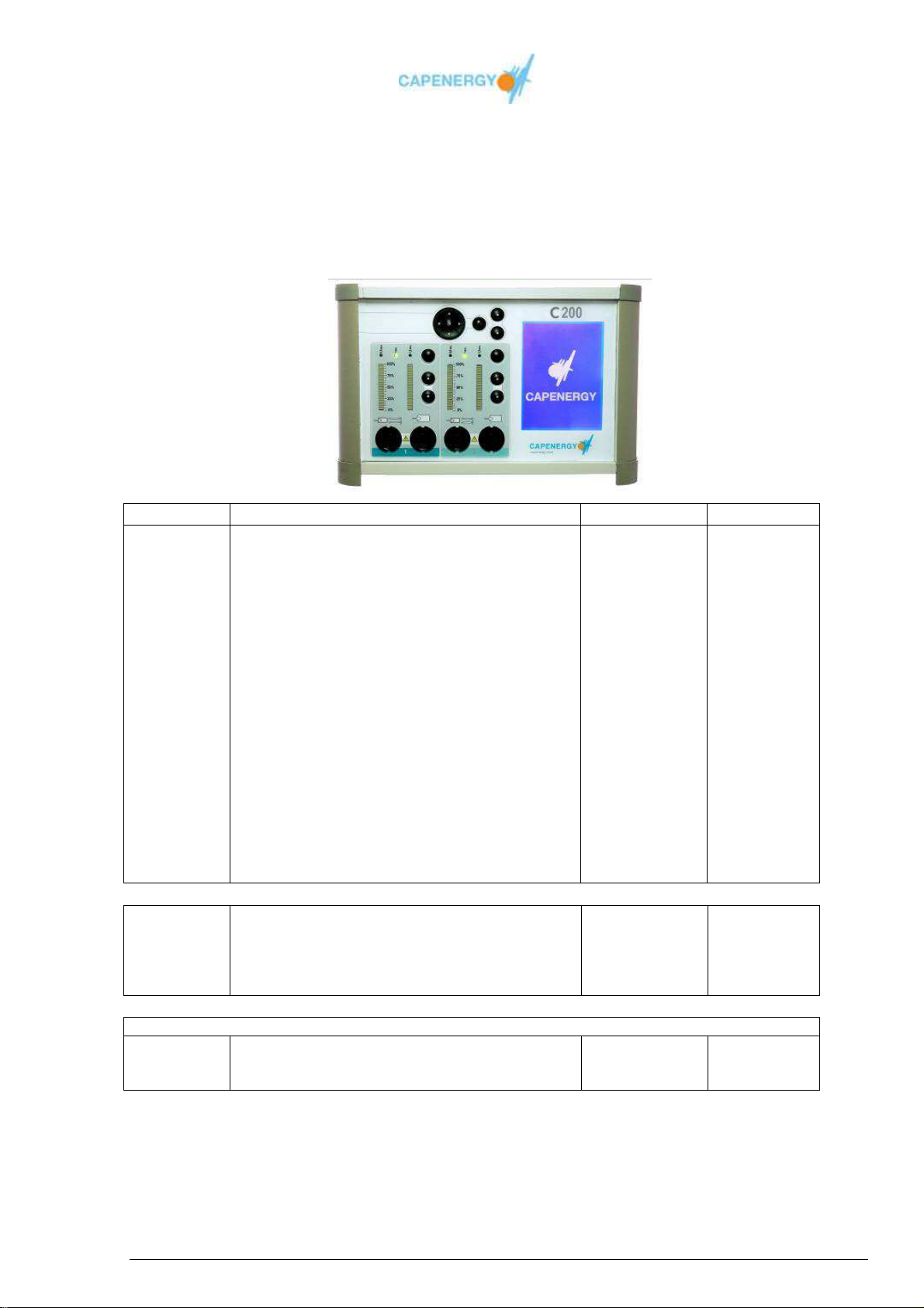
C 200
Ref 5330002
Device with 2 work channels: automatic and manual for individual or simultaneous use of
capacitive and/or resistive electrodes
Units Description Ref Equipment
1 Device C 200 5330002 Standard
1 User Manual 350200 Standard
2 Mains cord 080224 Standard
1 Safety control 5350070 Standard
2 Active plates with temperature sensor 5350037 Standard
2 Passive plates 5350038 Standard
2 Hygienic protective gel covers 5100013 Standard
2 Hygienic protective covers without gel 5100060 Standard
1 Straight resistive electrode holder 5350033 Standard
1 Straight capacitive electrode holder 5350034 Standard
1 Capacitive electrode 33 mm 5100025 Standard
1 Capacitive electrode 53 mm 5100027 Standard
1 Capacitive electrode 65 mm 5100028 Standard
1 Resistive electrode 33 mm 5100029 Standard
1 Resistive electrode 53 mm 5100031 Standard
1 Resistive electrode 65 mm 5100032 Standard
4 Elastic bandage 80 cm 5100028 Standard
4 Elastic bandage 60 cm 5100030 Standard
4 Elastic bandage 40 cm 5100029 Standard
1 Isolation transformer of 450VA 5100148 Standard
1 90º capacitive electrode holder 5350035 Optional
1 90º resistive electrode holder 5350036 Optional
1 Capacitive electrode 65 mm 5100028 Optional
1 Resistive electrode 65 mm 5100032 Optional
2 Active plates WITHOUT temperature sensor 5350039 Optional
UPGRADE TO C 500 : YES
1 Intracavitary accessory MJS 5350040 Upgrade
1 Box vaginal/rectal probe covers for intracavitary
accessory MJS (144 un. x box)
5100131 Upgrade
User Manual
Page 90 of 95
Page 91
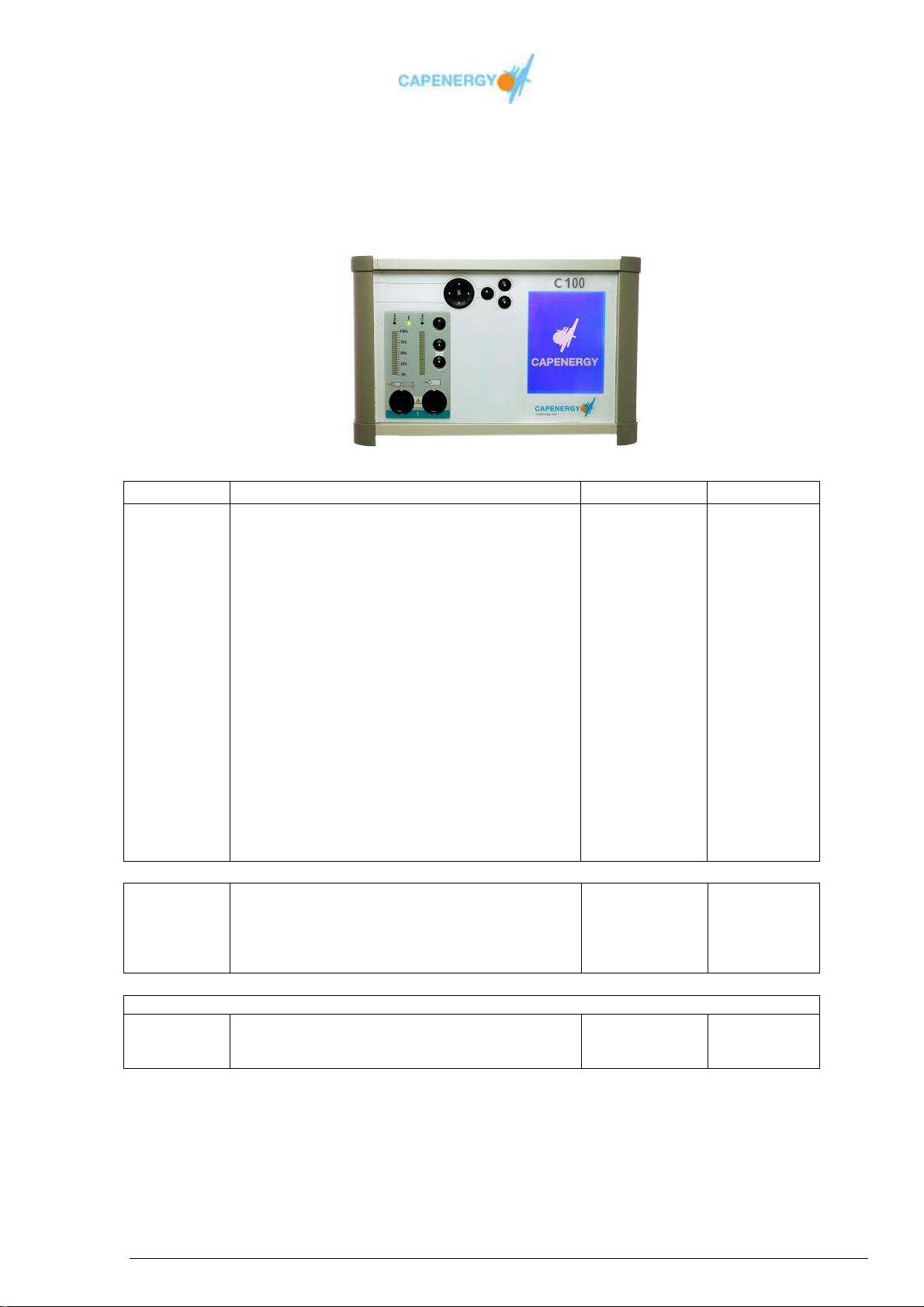
C 100
Ref 5330001
Device with 1 work channel: automatic or manual capacitive or resistive.
Units Description Ref Equipment
1 Device C 100 5330001 Standard
1 User Manual 350200 Standard
2 Mains cord 080224 Standard
1 Safety control 5350070 Standard
1 Active plate with temperature sensor 5350037 Standard
1 Passive plate 5350038 Standard
1 Hygienic protective gel covers 5100013 Standard
1 Hygienic protective covers without gel 5100060 Standard
1 Straight resistive electrode holder 5350033 Standard
1 Straight capacitive electrode holder 5350034 Standard
1 Capacitive electrode 33 mm 5100025 Standard
1 Capacitive electrode 53 mm 5100027 Standard
1 Capacitive electrode 65 mm 5100028 Standard
1 Resistive electrode 33 mm 5100029 Standard
1 Resistive electrode 53 mm 5100031 Standard
1 Resistive electrode 65 mm 5100032 Standard
2 Elastic bandage 80 cm 5100028 Standard
2 Elastic bandage 60 cm 5100030 Standard
2 Elastic bandage 40 cm 5100029 Standard
1 Isolation transformer of 450VA 5100148 Standard
1 90º capacitive electrode holder 5350035 Optional
1 90º resistive electrode holder 5350036 Optional
1 Capacitive electrode 65 mm 5100028 Optional
1 Resistive electrode 65 mm 5100032 Optional
1 Active plates WITHOUT temperature sensor 5350039 Optional
UPGRADE TO C 500 : YES
1 Intracavitary accessory MJS 5350040 Upgrade
1 Box vaginal/rectal probe covers for intracavitary
accessory MJS (144 un. x box)
5100131 Upgrade
User Manual
Page 91 of 95
Page 92
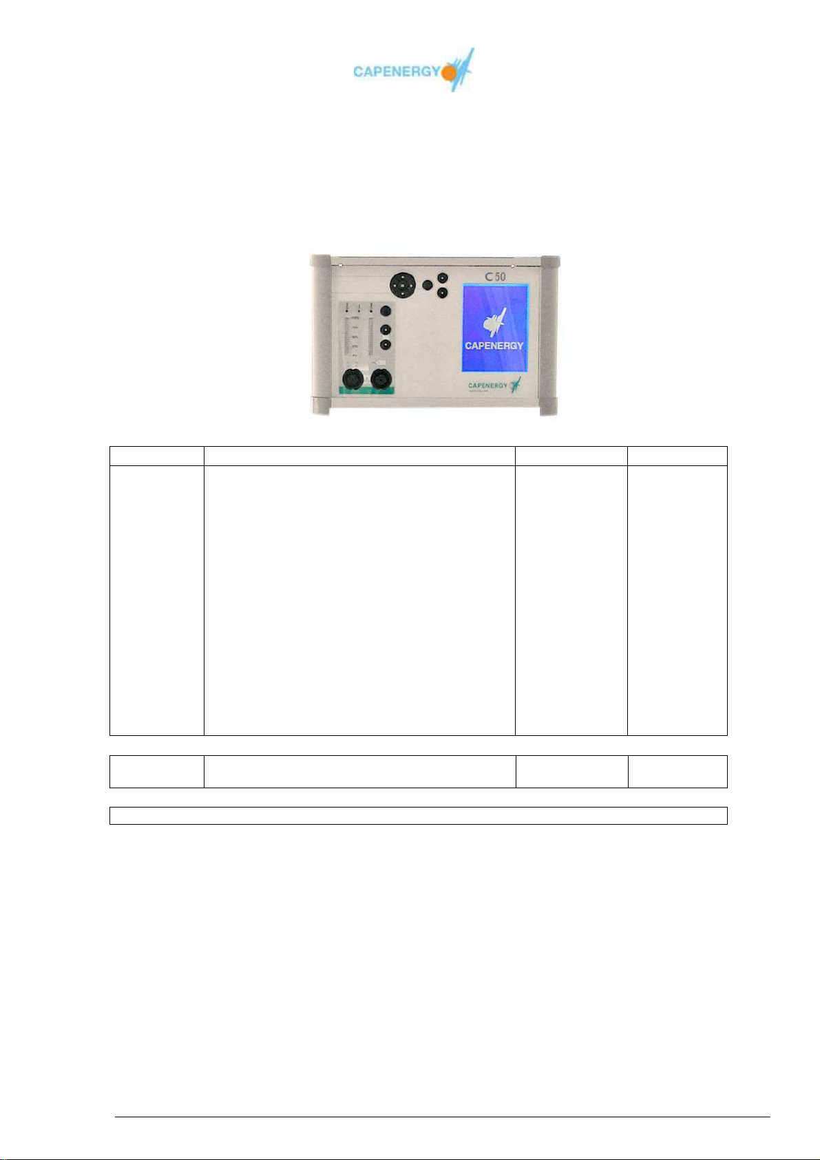
C 50
Ref. 5330050
Exclusively manual devie with 1 capacitive or resistive work channel
Units Description Ref Equipment
1 Device C 50 5330050 Standard
1 User Manual 350200 Standard
2 Mains cord 080224 Standard
1 Safety control 5350070 Standard
1 Passive plate 5350038 Standard
1 Straight resistive electrode holder 5350033 Standard
1 Straight capacitive electrode holder 5350034 Standard
1 Capacitive electrode 33 mm 5100025 Standard
1 Capacitive electrode 53 mm 5100027 Standard
1 Capacitive electrode 65 mm 5100028 Standard
1 Resistive electrode 33 mm 5100029 Standard
1 Resistive electrode 53 mm 5100031 Standard
1 Resistive electrode 65 mm 5100032 Standard
2 Elastic bandage 80 cm 5100028 Standard
2 Elastic bandage 60 cm 5100030 Standard
2 Elastic bandage 40 cm 5100029 Standard
1 Isolation transformer of 450VA 5100148 Standard
1 90º capacitive electrode holder 5350035 Optional
1 90º resistive electrode holder 5350036 Optional
UPGRADE TO C 500 : NO
User Manual
Page 92 of 95
Page 93
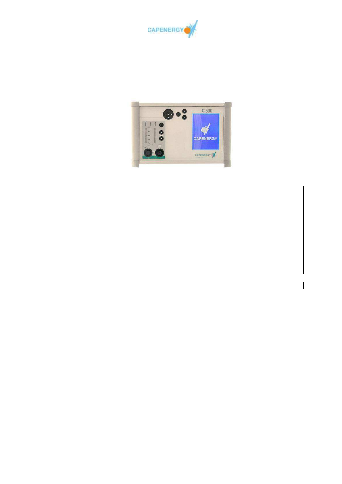
C 500
Ref 5330005
Device designed specifically for URO-GINECOLOGICALtreatments, with 1 intracavitary
manual electrode (1 work channel)
Units Description Ref Equipment
1 Device C 500 5330005 Standard
1 User Manual 350200 Standard
2 Mains cord 080224 Standard
1 Safety control 5350070 Standard
1 Intracavitary accessory MJS 5350040 Standard
1 Box vaginal/rectal probe covers for intracavitary
accessory MJS (144 unids x caja)
1 Passive plate 5350038 Standard
2 Elastic bandage 80 cm 5100028 Standard
2 Elastic bandage 60 cm 5100030 Standard
2 Elastic bandage 40 cm 5100029 Standard
1 Isolation transformer of 450VA 5100148 Standard
UPGRADE TO C 100 : YES
5100131 Standard
User Manual
Page 93 of 95
Page 94

Appendix H
INTELLECTUAL PROPERTY
INTELLECTUAL PROPERTY RIGHTS
CAPENERGY MEDICAL, SL is the exclusive owner of all graphic material, pictures,
logotypes, publications or press communications spread over the internet in
representation of the commercial brand CAPENERGY and holds the exploitation rights
on the fore-mentioned information, as well as the contents of this USER AND
MAINTENANCE MANUAL.
Updated information regarding new products is available on the official CAPENERGY
website and can be consulted in printed or telematic version for its incorporation in
articles, press notes or publications in which the author explicitly mentions CAPENERGY
and reflects the contents in a reliable and unmodified way.
UNDER NO CIRCUMSTANCES MAY THE CONTENTS OF THIS USER AND
MAINTENANCE MANUAL BE DISCLOSED. THEY ARE EXCLUSIVELY FOR THE USE
OF CIM USERS THAT OWN A PROFESSIONAL CAPENERGY DEVICE.
Under no circumstances may this information be modified or used in a way that harmful
to CAPENERGY, who will have the right to claim damages caused by the inappropriate
use of its intellectual property by third parties.
Should you wish to use any of the information for publication, please contact
CAPENERY MEDICAL by writing. The board of directors will then decide according to its
criteria whether or not to grant the corresponding authorization.
As the owner of the intellectual property, CAPENERGY reserves all the rights to
undertake legal action aimed at the legitimate defense of its own contents..
For further information, please consult the website http://www.capenergy.com
User Manual
Page 94 of 95
Page 95

CAPENERGY MEDICAL S. L.U
Av. Mare de Déu de Montserrat, 41 - Pasaje 1º Derecha
Polígono Industrial Font Santa
08970 Sant Joan Despí (Barcelona)
España (SPAIN)
Tel. : + 34 (93) 477.43.48
Fax : + 34 (93) 477.42.90
www.capenergy.com
User Manual
Page 95 of 95
 Loading...