

Page 1
0103 Part No. X09-33240 XM
capcom-europe.com
M
Page 2

1
CONTROLLER SETUP . . . . . . . . . . . . . . . . . . . . . . . . . . . . . . . . . . . . . . . . . . . 2
Precautions . . . . . . . . . . . . . . . . . . . . . . . . . . . . . . . . . . . . . . . . . . . . 2
Troubleshooting . . . . . . . . . . . . . . . . . . . . . . . . . . . . . . . . . . . . . . . . . 2
Right Unit Assembly . . . . . . . . . . . . . . . . . . . . . . . . . . . . . . . . . . . . . . 2
Left Unit Assembly . . . . . . . . . . . . . . . . . . . . . . . . . . . . . . . . . . . . . . . 2
SECTION 1. VT CONCEPT AND SPECIAL PANZER DIVISION . . . . . . . . . . . . . . 4
1-1 VT Concept . . . . . . . . . . . . . . . . . . . . . . . . . . . . . . . . . . . . . . . . . . . 4
1-2 Basics of the Military Use VT . . . . . . . . . . . . . . . . . . . . . . . . . . . . . 4
1-3 Duties of the Special Armoured Unit . . . . . . . . . . . . . . . . . . . . . . 4
1-4 Special Panzer Division Formation . . . . . . . . . . . . . . . . . . . . . . . . 4
1-5 VT Platoon Operation . . . . . . . . . . . . . . . . . . . . . . . . . . . . . . . . . . 4
SECTION 2. VT SUMMARY . . . . . . . . . . . . . . . . . . . . . . . . . . . . . . . . . . . . . . . 5
2-1 Basic VT Parts . . . . . . . . . . . . . . . . . . . . . . . . . . . . . . . . . . . . . . . . 5
2-2 VT Operation System . . . . . . . . . . . . . . . . . . . . . . . . . . . . . . . . . . 5
2-3 VT Types . . . . . . . . . . . . . . . . . . . . . . . . . . . . . . . . . . . . . . . . . . . . 6
2-4 Movement . . . . . . . . . . . . . . . . . . . . . . . . . . . . . . . . . . . . . . . . . . 6
2-5 Fuel Tank and Spare Tanks . . . . . . . . . . . . . . . . . . . . . . . . . . . . . 6
2-6 Fuel Consumption and Estimated Movement Time . . . . . . . . . . . 6
2-7 Defensive Armour . . . . . . . . . . . . . . . . . . . . . . . . . . . . . . . . . . . . 6
2-8 Main Weapon and Sub Weapon . . . . . . . . . . . . . . . . . . . . . . . . . 6
2-9 Maximum Weapon Weight Allowance . . . . . . . . . . . . . . . . . . . . 6
2-10 Weapons Loaded on the VT . . . . . . . . . . . . . . . . . . . . . . . . . . . . 7
2-11 Targeting of Curve Trajectory Weapons on War Map . . . . . . . . 12
2-12 Short Fuse . . . . . . . . . . . . . . . . . . . . . . . . . . . . . . . . . . . . . . . . . . 12
2-13 Chaff Defence . . . . . . . . . . . . . . . . . . . . . . . . . . . . . . . . . . . . . . . 12
SECTION 3. SPECIAL FUNCTIONS
THROUGH 2ND GENERATION COOS . . . . . . . . . . . . . . . . . . . . . . . . . . . . . . 12
3-1 Additions for 2nd Generation COOS . . . . . . . . . . . . . . . . . . . . . . 12
3-2 FSS (Target Estimating Firing System) Function . . . . . . . . . . . . . . 12
3-3 Overdrive Function . . . . . . . . . . . . . . . . . . . . . . . . . . . . . . . . . . . 12
3-4 Stealth Function . . . . . . . . . . . . . . . . . . . . . . . . . . . . . . . . . . . . . . 12
3-5 Guided Weapons . . . . . . . . . . . . . . . . . . . . . . . . . . . . . . . . . . . . . 12
SECTION 4. VT CONTROLS . . . . . . . . . . . . . . . . . . . . . . . . . . . . . . . . . . . . . . 13
4-1 Startup Sequence . . . . . . . . . . . . . . . . . . . . . . . . . . . . . . . . . . . . . 13
4-2 When Stalling the VT During Startup . . . . . . . . . . . . . . . . . . . . . . 13
Basic Controls . . . . . . . . . . . . . . . . . . . . . . . . . . . . . . . . . . . . . . . . . . 14
4-3 Moving and Stopping . . . . . . . . . . . . . . . . . . . . . . . . . . . . . . . . . . 14
4-4 Acceleration and Deceleration . . . . . . . . . . . . . . . . . . . . . . . . . . 14
4-5 Rotation . . . . . . . . . . . . . . . . . . . . . . . . . . . . . . . . . . . . . . . . . . . . 14
4-6 Overdrive . . . . . . . . . . . . . . . . . . . . . . . . . . . . . . . . . . . . . . . . . . 14
4-7 Slidestep Function . . . . . . . . . . . . . . . . . . . . . . . . . . . . . . . . . . . . 14
4-8 Slidestep Functional Limitations . . . . . . . . . . . . . . . . . . . . . . . . . 14
4-9 Slidestep Tip Regulator . . . . . . . . . . . . . . . . . . . . . . . . . . . . . . . . 14
4-10 Cut-off Function . . . . . . . . . . . . . . . . . . . . . . . . . . . . . . . . . . . . . 14
4-11 Manipulator Controls . . . . . . . . . . . . . . . . . . . . . . . . . . . . . . . . . 15
VT Monitor . . . . . . . . . . . . . . . . . . . . . . . . . . . . . . . . . . . . . . . . . . . . 16
4-12 Main Camera Change . . . . . . . . . . . . . . . . . . . . . . . . . . . . . . . . . 16
4-13 Main Camera Dust and Dirt . . . . . . . . . . . . . . . . . . . . . . . . . . . . 16
4-14 Sub Monitor Functions . . . . . . . . . . . . . . . . . . . . . . . . . . . . . . . . 17
4-15 Night Vision Equipment . . . . . . . . . . . . . . . . . . . . . . . . . . . . . . . 17
JCS (Complete Command System) . . . . . . . . . . . . . . . . . . . . . . . . . . . 17
4-16 JCS (Complete Command System) Summary . . . . . . . . . . . . . . . 17
4-17 Multi-Monitor Display . . . . . . . . . . . . . . . . . . . . . . . . . . . . . . . . 18
4-18 Information Displayed in the Multi-Monitor . . . . . . . . . . . . . . . 18
Emergency Procedures . . . . . . . . . . . . . . . . . . . . . . . . . . . . . . . . . . . . . . . 19
4-19 Evacuation Setup . . . . . . . . . . . . . . . . . . . . . . . . . . . . . . . . . . . . 19
4-20 Emergency Eject Switch . . . . . . . . . . . . . . . . . . . . . . . . . . . . . . 19
4-21 Emergency Escape Procedures in Rivers or Seas . . . . . . . . . . . 19
4-22 Fire in the Hull . . . . . . . . . . . . . . . . . . . . . . . . . . . . . . . . . . . . . 19
SECTION 5. VT ATTACK . . . . . . . . . . . . . . . . . . . . . . . . . . . . . . . . . . . . . . . 20
5-1 Weapon Targeting and Shooting . . . . . . . . . . . . . . . . . . . . . . . . 20
5-2 Lock-On Function . . . . . . . . . . . . . . . . . . . . . . . . . . . . . . . . . . . . 20
5-3 Close Combat Targeting . . . . . . . . . . . . . . . . . . . . . . . . . . . . . . . 20
5-4 FSS (Target Estimating Firing System) . . . . . . . . . . . . . . . . . . . . . 21
5-5 Firing Ranges of Different Weapons . . . . . . . . . . . . . . . . . . . . . . 21
5-6 Notes on Firing Within Effective Target Range . . . . . . . . . . . . . . 21
5-7 Using Effective Target Range . . . . . . . . . . . . . . . . . . . . . . . . . . . . 22
5-8 Land Suppression Attack . . . . . . . . . . . . . . . . . . . . . . . . . . . . . . 22
5-9 Weapon Change . . . . . . . . . . . . . . . . . . . . . . . . . . . . . . . . . . . . . 22
5-10 Reloading Magazine Weapons . . . . . . . . . . . . . . . . . . . . . . . . . 22
SECTION 6. VT MOVEMENT . . . . . . . . . . . . . . . . . . . . . . . . . . . . . . . . . . . . 23
6-1 In General . . . . . . . . . . . . . . . . . . . . . . . . . . . . . . . . . . . . . . . . . . 23
6-2 Using Weather and Topography . . . . . . . . . . . . . . . . . . . . . . . . . 23
STEEL BATTALION CONTROLLER CONFIGURATION . . . . . . . . . . . . . . . . . . 24
SECTION 7. PLATOON STRATEGY PREPARATIONS . . . . . . . . . . . . . . . . . . . 26
7-1 Orders . . . . . . . . . . . . . . . . . . . . . . . . . . . . . . . . . . . . . . . . . . . . . 26
7-2 Mission Analysis . . . . . . . . . . . . . . . . . . . . . . . . . . . . . . . . . . . . . 26
7-3 Choosing Weapons . . . . . . . . . . . . . . . . . . . . . . . . . . . . . . . . . . . 26
7-4 Selection of Additional Armour and Sub-Weapons . . . . . . . . . . 26
7-5 Choosing your VT . . . . . . . . . . . . . . . . . . . . . . . . . . . . . . . . . . . . 26
7-6 Attaching Extra Fuel Tanks and Armour . . . . . . . . . . . . . . . . . . 26
7-7 Supply Requests . . . . . . . . . . . . . . . . . . . . . . . . . . . . . . . . . . . . . 26
7-8 Fixed VT Food Provisions . . . . . . . . . . . . . . . . . . . . . . . . . . . . . . 26
7-9 Bringing Personal Effects into the Cockpit . . . . . . . . . . . . . . . . . 26
SECTION 8. RADIO TRANSMISSIONS
8-1 Summary . . . . . . . . . . . . . . . . . . . . . . . . . . . . . . . . . . . . . . . . . . . 27
8-2 Pre-set Channels . . . . . . . . . . . . . . . . . . . . . . . . . . . . . . . . . . . . . 27
8-3 Radio Communication Procedures . . . . . . . . . . . . . . . . . . . . . . . 27
8-4 Sending a Message . . . . . . . . . . . . . . . . . . . . . . . . . . . . . . . . . . . 28
8-5 Receiving a Message . . . . . . . . . . . . . . . . . . . . . . . . . . . . . . . . . . 28
8-6 Repeating the Message . . . . . . . . . . . . . . . . . . . . . . . . . . . . . . . 28
SECTION 9. SUPPLY . . . . . . . . . . . . . . . . . . . . . . . . . . . . . . . . . . . . . . . . . . 29
9-1 Accepting Supplies . . . . . . . . . . . . . . . . . . . . . . . . . . . . . . . . . . . 29
9-2 Classifying Supplies . . . . . . . . . . . . . . . . . . . . . . . . . . . . . . . . . . 29
9-3 Supply via Supply Helicopter . . . . . . . . . . . . . . . . . . . . . . . . . . . 29
9-4 Choices and Cautions when Receiving Supplies . . . . . . . . . . . . 29
9-5 Opening of Supply Issuance Centre . . . . . . . . . . . . . . . . . . . . . . 29
SECTION 10. LEADERSHIP . . . . . . . . . . . . . . . . . . . . . . . . . . . . . . . . . . . . . . 30
10-1 Leadership Duties . . . . . . . . . . . . . . . . . . . . . . . . . . . . . . . . . . . 30
10-2 Necessary Qualities for a Commander . . . . . . . . . . . . . . . . . . . 30
10-3 Orders During Battle . . . . . . . . . . . . . . . . . . . . . . . . . . . . . . . . . 30
TECHNICAL APPENDIX . . . . . . . . . . . . . . . . . . . . . . . . . . . . . . . . . . . . . . . . 32
Cockpit: 1st Generation . . . . . . . . . . . . . . . . . . . . . . . . . . . . . . . . . . . 32
Main Monitor Display: 1st Generation . . . . . . . . . . . . . . . . . . . . . . . 32
Cockpit: 2nd Generation . . . . . . . . . . . . . . . . . . . . . . . . . . . . . . . . . . 33
Main Monitor Display: 2nd Generation . . . . . . . . . . . . . . . . . . . . . . 33
Cockpit: 3rd Generation . . . . . . . . . . . . . . . . . . . . . . . . . . . . . . . . . . 34
Main Monitor Display: 3rd Generation . . . . . . . . . . . . . . . . . . . . . . 34
Warranty . . . . . . . . . . . . . . . . . . . . . . . . . . . . . . . . . . . . . . . . . . . . . . 35
Customer Support . . . . . . . . . . . . . . . . . . . . . . . . . . . . . . . . . . . . . . 181
ENGLISH
BEFORE PLAYING THE GAME
Thank you for purchasing STEEL BATTALION. Make sure you read
all the instruction manuals before playing the game. After
reading the manuals, keep them nearby in a safe place so you
can refer to them quickly and easily.
WARNINGS
• Store the unit and all components away from children.
•Do not open or modify the unit or components.
• Do not spill water on the unit or components.
• Store the unit and components in a dry, dust-free location.
• If a problem should arise, stop use immediately.
TABLE OF CONTENTS
SAFETY INFORMATION
ABOUT PHOTOSENSITIVE SEIZURES
A very small percentage of people may experience a seizure
when exposed to certain visual images, including flashing lights
or patterns that may appear in video games. Even people who
have no history of seizures or epilepsy may have an
undiagnosed condition that can cause these “photosensitive
epileptic seizures” while watching video games.
These seizures may have a variety of symptoms, including
lightheadedness, altered vision, eye or face twitching, jerking or
shaking of arms or legs, disorientation, confusion, or
momentary loss of awareness. Seizures may also cause loss of
consciousness or convulsions that can lead to injury from
falling down or striking nearby objects.
Immediately stop playing and consult a doctor if you experience
any of these symptoms. Parents should watch for or ask their
children about the above symptoms—children and teenagers are
more likely than adults to experience these seizures.
The risk of photosensitive epileptic seizures may be reduced by
sitting farther from the television screen, using a smaller
television screen, playing in a well-lit room, and not playing
when you are drowsy or fatigued.
If you or any of your relatives have a history of seizures or
epilepsy, consult a doctor before playing.
Other Important Health and Safety Information. The Xbox
Instruction Manual contains important health and safety
information that you should read and understand before using
this software.
AVOID DAMAGE TO YOUR TELEVISION
Do not use with certain televisions. Some televisions, especially
front- or rear-projection types, can be damaged if any video
games, including Xbox games, are played on them. Static images
presented during the normal course of game play may “burn in”
to the screen, causing a permanent shadow of the static image
to appear at all times, even when video games are not being
played. Similar damage may occur from static images created
when placing a video game on hold or pause. Consult your
television owner’s manual to determine if video games can be
played safely on your set. If you are unable to find this
information in the owner’s manual, contact your television
dealer or the manufacturer to determine if video games can be
played safely on your set.
Unauthorized copying, reverse engineering, transmission, public
performance, rental, pay for play, or circumvention of copy
protection is strictly prohibited.
Page 3
2 3
CONTROLLER SETUP
PRECAUTIONS
• Do not plug more than 2
STEEL BATTALION
controllers
into the same Xbox unit.
• Do not touch the aiming lever or selection lever when
connecting the
STEEL BATTALION
controller or turning
on the power.
• When attaching
STEEL BATTALION
controller pieces, do
not mix up the left unit with the right unit. Be sure to attach
them in their correct positions.
• The
STEEL BATTALION
controller is made with small,
precision parts. Do not put anything on it or place it on an
unstable shelf.
• Always turn the Xbox console off before removing the
STEEL
BATTALION
controller.
•When cleaning the
STEEL BATTALION
controller, make
sure you turn the power off beforehand. Clean the controller
with a soft, dry towel. Do not use oil as it could cause fading or
possible deformation of the unit.
• Do not drop the
STEEL BATTALION
controller.
• Do not forcibly bend the cable, pull it out or place a heavy item
on it.
• When removing the cable, make sure you hold the area that
attaches to the Xbox console to pull out the cable.
• Do not store the
STEEL BATTALION
controller in
locations subject to extreme heat or cold, or where water or
dampness could be present.
• Use the
STEEL BATTALION
controller for its intended
purpose only.
TROUBLESHOOTING
Before sending the
STEEL BATTALION
controller out to be
repaired, please perform the following checks:
The controller does not respond –
• Reconnect the controller from the beginning and restart the
machine.
The aiming lever LED light does not come on –
• Move the shift lever over to a position where the LED will light
up. Leaving the lever in a position where it will not light up for
extended periods could cause the LED to stop lighting up.
RIGHT UNIT ASSEMBLY
Warning: Do not mix up the right and left units. Make sure you
connect them in their correct positions.
1. Connect the centre unit and the right unit by inserting the
connector cable into the jacks in both units.
ATTENTION: You must connect the cable end to the centre unit
in the correct position. Check the direction in which the cable
must be facing before attempting to plug it into the unit.
2. Make sure you insert the connector cable ends all the way into
the jacks. Failure to do so could cause the controller not to
operate.
3. Make sure the connector cable is not pinched between the two
units.
WARNING: Pulling on the connector cable too roughly can
break the wires inside and make the unit unusable.
4. Firmly attach the connector unit cover. A small R or Lis written
on the back of each connector unit cover. Use the R cover with
the right unit and the L cover with the left unit.
5. Insert the screws into the four connector holes in the
connector unit cover. Use the Alan wrench attached to the
underside of the centre unit for this purpose.
6. Tighten the screws to finish.
LEFT UNIT ASSEMBLY
Follow the same steps as for connecting the right unit (above).
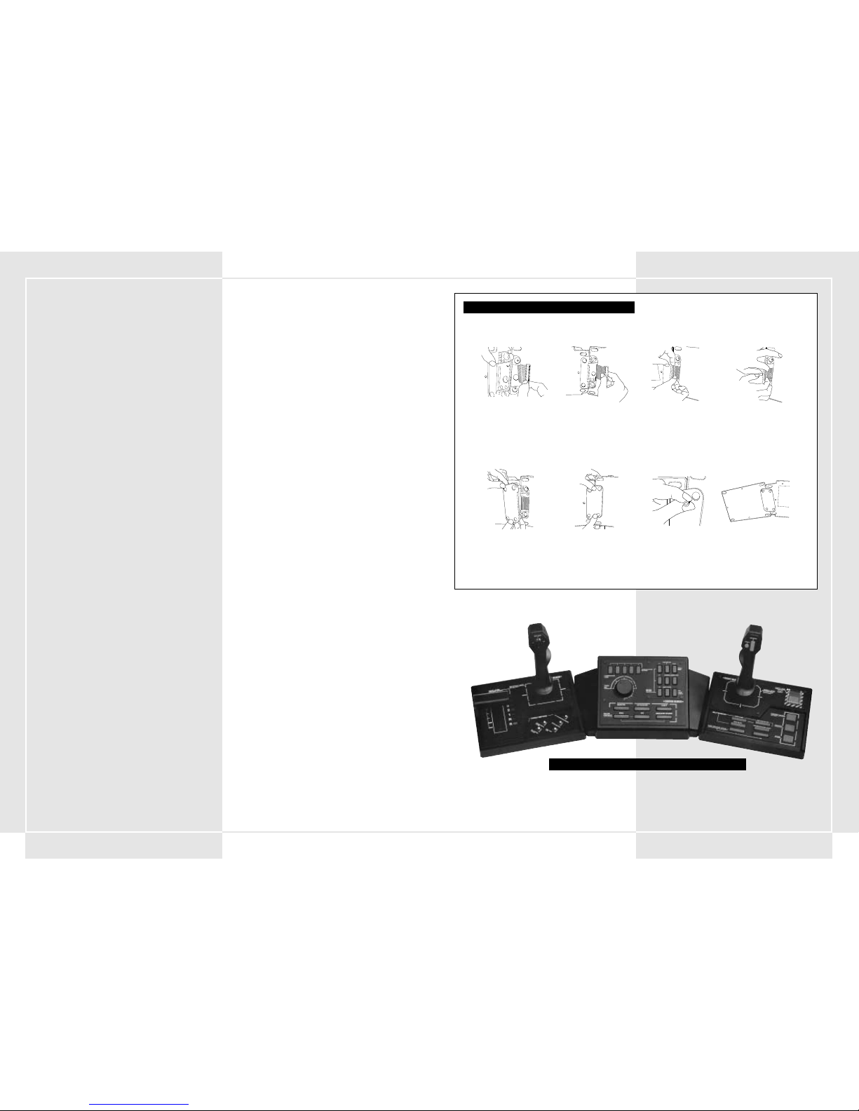
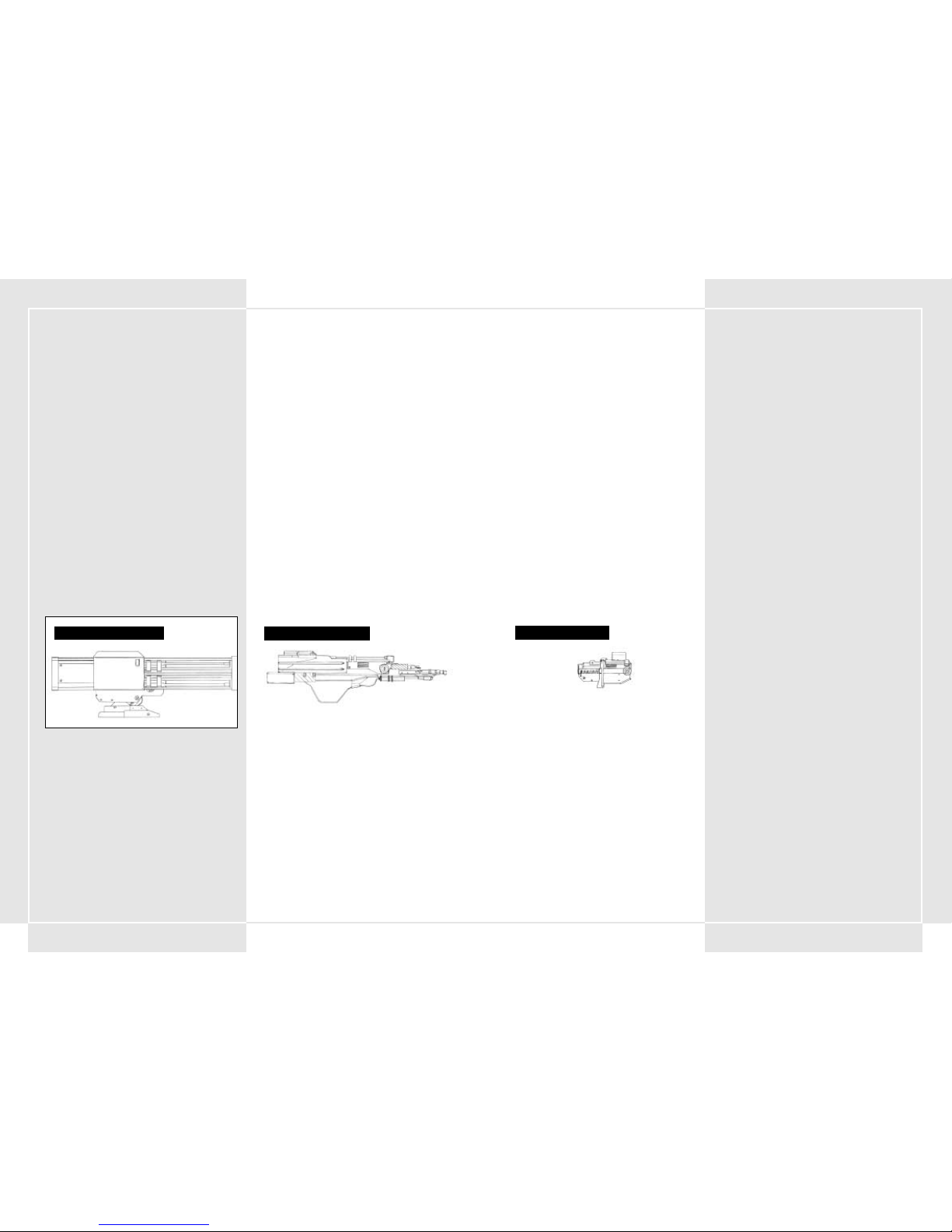
FULLY ASSEMBLED STEEL BATTALION CONTROLLER
STEEL BATTALION CONTROLLER ASSEMBLY
Connect the centre unit and the right unit by inserting the connector cable into the jacks in both units.
Make sure you insert the connector cable ends all the way into the jacks.
Firmly attach the connector unit cover.
Insert the screws into the four connector holes in the connector unit cover and tighten them.
ABC
D
EFG
H
Page 4
4 5
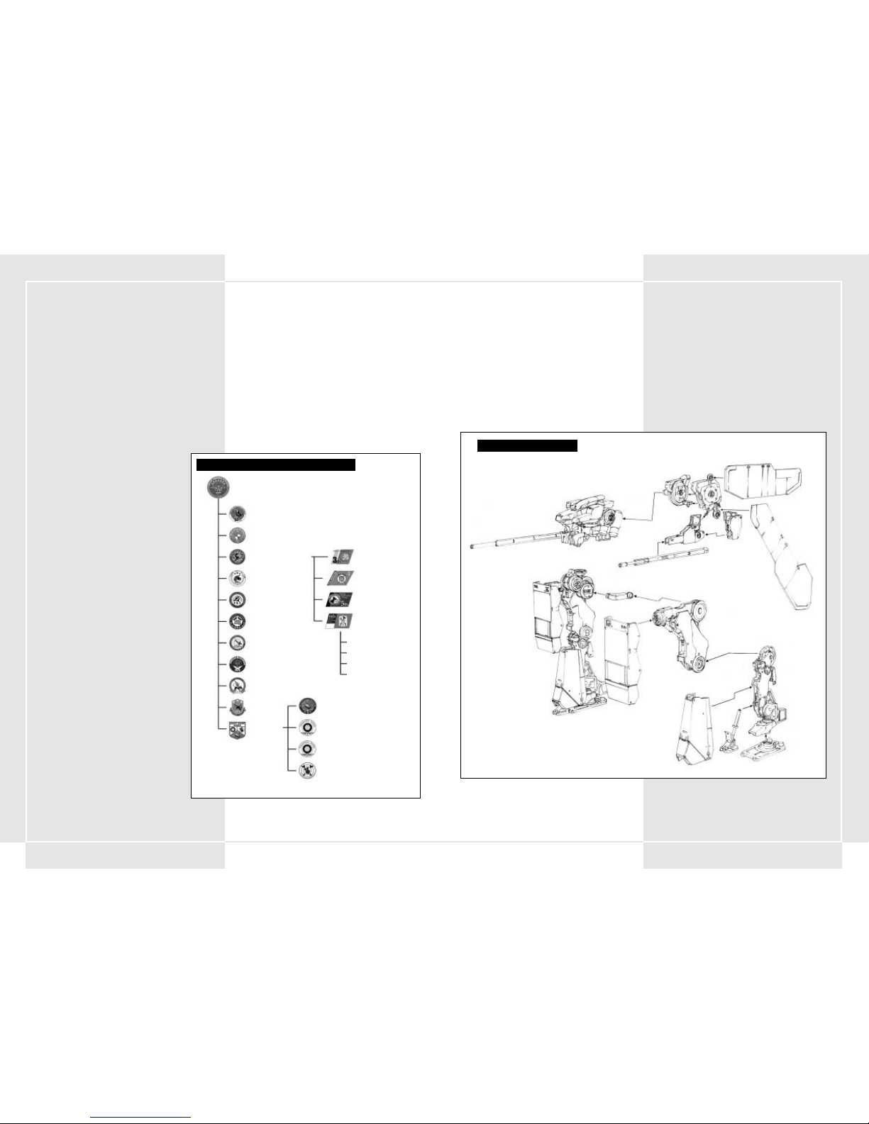
2-1 BASIC VT PARTS
VTs are basically formed from three major units:
1. Main body unit
2. Leg unit
3. Weapons unit
Some weapons units mount directly onto the main body unit,
while others work independently.
2-2 VT OPERATION SYSTEM
The VT operation is controlled with an OS known as the COOS. It
controls the balancer in the leg unit as well as the targeting
system for various weapons. Even if the VT type is the same, in
cases where the loaded OS is different the battlefield
performance is greatly reduced. The COOS, perfected through
numerous experiments as well as on the battlefield, is one of the
army’s greatest secrets. Pilots must be aware of this fact, and if
they eject during battle the VT must be destroyed to protect this
technology.
1-1 VT CONCEPT
The VT (Vertical Tank) has a short history and has only been used
as a weapon for the last eight years. However, due to the fact that
so many different organisations have started using the VT, it has
great potential as a military weapon.
Military development has become saturated, and due to arms
reduction, many military projects and unnecessary armies have
been cut. The VT, with its impressive firepower potential and
ability to be piloted by one person, will be used as a replacement
for armoured tanks, and will no doubt be the main weapon of
most organisations.
1-2 BASICS OF THE MILITARY USE VT
Until now, the VT has not been in general use as a military
weapon. It has been used experimentally in local conflicts only
twice. Currently, documentation concerning its
military use is not complete. In order for the VT to
reach its full potential, we must wait for research to
be completed. The VT’s military potential will
increase based upon the size and scope of future
conflicts. The VT will mainly be used as a powerful
heavy firepower weapon, and will be effective when
put into battle in mass numbers. One other major
point that must be considered is that the VT has not
been in use for as long, comparatively, as other
previous weapons/vehicles. Therefore in order to
maintain the VT’s military power, back-up
reinforcements will be invaluable.
1-3 DUTIES OF THE SPECIAL ARMOURED
UNIT
The role of the Panzer Unit that uses the VT as
military equipment will be to carry out extremely
important duties. In a mobile infantry battle, the
Armored Unit will be used to destroy the enemy,
capture key enemies, take over different enemy
encampments, and occupy and maintain areas. The
VT will mainly be used as a mobile platoon attacker
and counterattacking defensive unit. Also, since
time and topography are not a concern of the VT, it
will serve as a key unit when attacking areas with
problematic topography. The VT when used in
conjunction with mobile units (tanks) will increase
the firepower of the entire force. Sometimes it will
be used with air forces or sea forces in order to take
over key locations and when engaging in strategies
for attacking behind enemy lines.
1-4 SPECIAL PANZER DIVISION
FORMATION
A Panzer Division is formed of a command outpost,
3 VT battalions, 1 tank battalion, 1 artillery battalion,
1 recon battalion, 1 engineering battalion, 1
communications battalion, 1 anti-aircraft battalion, 1
air battalion, and 1 reinforcement battalion (see the
chart on the right). The reinforcement division is
composed of a supply battalion, a weapons
maintenance battalion, a transport battalion, and a
medic battalion. The VT battalion is composed of 4
VT companies. In each company there are 3 VT
platoons and 1 firearm support platoon (with 3
machines in each platoon). The firearm support
platoon is basically assigned a supportive role and
will never attack independently.
1-5 VT PLATOON OPERATION
One VT platoon is composed of 3 pilots who operate the small,
middle, and heavy classes of VTs. The VT type is chosen based on
the type of mission that has been assigned. Before a mission
begins, the pilot puts in his VT type request. VT transportation
and equipment for VT platoons come from the VT equipping
battalion and are shipped to the various companies which then
use transports to distribute the material to the various channels.
There are 3 VT repairmen (1 head repairman and 2 regular
repairmen) assigned to each VT. A commissioned chief equipment
officer is assigned based on VT type. He controls all equipment.
VT platoons are regularly dependent on company transports to
get equipment, but during emergency battle situations they rely
on division reinforcement supply battalions. Also, the weapons
maintenance battalion is in charge of large-scale operations such
as changing entire sets of parts.
SECTION 1. VT CONCEPT AND SPECIAL PANZER DIVISION SECTION 2. VT SUMMARY
VT STRUCTURE DIAGRAM
Ball Joint Area (x axis)
x,y axis
z axis
x axis
x axis
Direction changes are driven by these parts
Ball Joint Area
Ball Joint Area
7th Special Panzer Division
32nd Special Armoured Battalion
33rd Special Armoured Battalion
34th Special Armoured Battalion
3rd Special Armoured Company
4th Special Armoured Company
5th Special Armoured Company
6th Special Armoured Company
‡VT Platoon
‡VT Platoon
‡VT Platoon
‡ Firearm Support
Platoon
Supply Battalion
Transport Battalion
Medic Battalion
Weapons Maintenance Battalion
80th Tank Battalion
Reconnaissance Battalion
Engineering Battalion
Anti-aircraft Battalion
Communications Battalion
Air Battalion
Artillery Battalion
Reinforcements
SPECIAL PANZER DIVISION FORMATION
Page 5

6 7
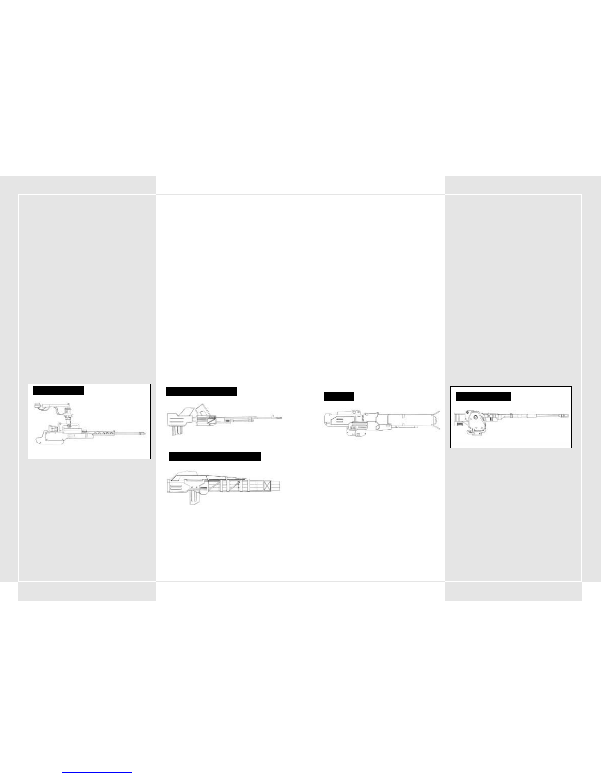
2-10 WEAPONS LOADED ON THE VT
270mm RIFLE
This weapon fires low-trajectory armour-piercing ammunition.
200mm ASSAULT RIFLE
Although its range is limited, the rapid self-loading system
promises the highest rapid-fire capability.
270mm ASSAULT RIFLE
With a maximum of 5-round rapid-fire action, this weapon has
plenty of destructive power to serve as the main anti-VT weapon.
However, compared with other models of the same generation, its
range is relatively short.
315mm TWIN RIFLE
This weapon fires two armour-piercing bullets simultaneously.
315mm RAPID FIRE RIFLE
With its three-round burst capability, this weapon has a higher
rapid-fire efficiency than a normal rifle.
355mm RAPID FIRE RIFLE
With its three-round burst capability, this weapon has a higher
rapid-fire efficiency than a normal rifle.
320mm SNIPER RIFLE
This weapon is designed to take out targets from a great distance.
It has a greater range of fire than a normal rifle.
AK19-4A RECOILESS RIFLE
This gun fires high-explosive shells. It is lightweight and has
approximately the same firepower as the rifle. However, due to
the ammunition’s slow rate of velocity, it is relatively easy for the
enemy to evade it.
AK19-77 RECOILESS RIFLE
This gun fires high-explosive shells loaded with contact fuses. The
ammunition will explode and inflict damage even if it is not a
direct hit.
315mm SMOOTH BORE GUN
This weapon fires low-trajectory APFSDS ammunition. It also has
a longer range of fire, compared to the rifle.
2-3 VT TYPES
VTs are categorised by type based on their weight. There are
light, middle, and heavy types.
1. Light VTs
This is a model where the main focus is on mobility. It has
been developed for use in situations where you are chasing
after an enemy that is running away or for attacking enemy
bases after their main firepower has been destroyed. Light
VTs are capable of being transported by air and have been
designed to be dropped into key drop spots. They can be
essential for air assaults on bases.
2. Middle VTs
The average middle class operation VTs used as the main
firepower in the Special Panzer Division. One of their main
characteristics is that while they maintain a balance of
firepower and strong armour, they are agile and can move
quickly. Of the three types of VTs, this one is the most
numerous. This VT has the most variation possibilities
through add-on armour and weapons.
3. Heavy VTs
VTs with heavy armour and great firepower. They have less
movement than light or middle level VTs. With their heavy
firepower and armour, these VTs are mainly used to protect
key locations and bases.
2-4 MOVEMENT
The average movement of middle level VTs is 100 kilometres per
hour. They can move a maximum distance of 205 kilometres from
the hangar. These basic values can change based on maintenance
of parts, topography, and pilot’s ability.
The balancer, which controls the stability of the leg unit, affects
the movement of the VT. This ability is displayed in points. The
higher the balancer points, the more stability your VT will have.
2-5 FUEL TANK AND SPARE TANKS
A fixed fuel tank is loaded on the main body unit. The fuel
capacity of the tank differs with the type of tank used. The M-7
Decider VT (main force for the Pacific Rim Forces) has a capacity
of about 6000 gallons and can operate for about 5 minutes per
tank.
Some VTs have spare tanks that can increase operating time. The
amount of spare tanks on a VT differs depending on the VT type,
but on average a VT will only have one or two spare tanks.
A spare tank has a capacity of 6000 gallons.
By pressing the Tank Detach button on the main console you can
release your extra fuel tanks and lighten your VT speed,
increasing mobility. If you use up a spare fuel tank, make sure
you detach it quickly.
2-6 FUEL CONSUMPTION AND ESTIMATED
MOVEMENT TIME
You can refuel any fuel that has been used in battle by issuing a
request for a re-supply. If you are in a situation where you cannot
be re-supplied and you run out of fuel, there is the possibility
that your VT could be marooned.
In order to prevent such situations, pre-battle briefing will have
an estimated amount of movement time. Think about the amount
of necessary movement for each battle and then decide the
amount of spare fuel tanks that will be necessary.
The most fuel-efficient gear for the VT is 3rd gear, which offers
the best standard movement and speed while the VT is patrolling.
You can extend your amount of movement time by reducing the
number of times you do slidesteps and other such moves which
guzzle fuel.
2-7 DEFENSIVE ARMOUR
The VT’s defensive power is known as its “armour resistance.” A
gauge on the control panel shows four different levels of
resistance. Each time the VT is hit, it will take damage and the
gauge will decrease. As this decreases the pilot will be at risk. If
the gauge falls to danger levels a warning will be displayed. You
should either back off from battle or consider ejecting as soon as
possible. (For more on ejecting see sections 4-19 to 4-21.) You are
able to add additional armour to your VT depending on its type.
2-8 MAIN WEAPON AND SUB WEAPON
VT weapons are divided into main and sub categories. These
should be considered different to standard weapons. Basically,
main weapons are mounted onto the arm units of the VT, whereas
sub weapons are mounted on other areas. You can determine the
weapon type based on the location that weapon is mounted on.
Weapons are not categorised by strength.
2-9 MAXIMUM WEAPON WEIGHT ALLOWANCE
VT weapons should be considered to be options. Some weapons
can be used for any VT type, but others differ depending on
which VT they are attached to. You can choose three of each sub
and main weapon type. The weight in weapons that can be loaded
differs depending on the VT type. The maximum weapons weight
allowance (the total amount of weight in weapons that the VT is
capable of carrying) is displayed to help you choose.
a270mm RIFLE
Page 6
8
9
SQUALL - ANTI-VT GUIDED MORTAR
This is the only high-angle fire anti-VT weapon that has homing
capability.
RAILGUN A
This is the most recent weapon developed by the PRF. With the
use of an electro-magnetic pulse, this weapon fires its ammo at
hypervelocity speeds. It has an unparalleled long attack range
and firepower.
RAILGUN B
A railgun developed by the Hai Shi Dao. With the use of an
electro-magnetic pulse, this weapon fires its ammo at
hypervelocity speeds. It has an unparalleled long attack range
and firepower.
HVM LAUNCHER
This weapon fires jet propelled armour-piercing ammunition.
Although its range and firepower are of the highest class, it is not
equipped with a homing system.
225mm HOWITZER
This weapon fires grenade shells in a high-arc trajectory.
Although not too destructive, it is capable of inflicting damage in
a fixed radius upon impact. It is very effective against populated
areas of AFVs.
305mm HOWITZER
This weapon fires grenade shells in a high-arc trajectory.
Although not terribly destructive, it is capable of inflicting
damage in a fixed radius upon impact. It is very effective against
populated areas of AFVs.
370mm HOWITZER
This weapon fires grenade shells in a high-arc trajectory. It is
capable of inflicting damage to a fixed radius upon impact.
Depending on its use, it can be highly effective.
550mm HOWITZER
This weapon fires grenade shells in a high-arc trajectory. It is
very destructive and capable of inflicting tremendous damage to
a fixed radius upon impact.
8 CAPACITY MLRS (Multiple Launch Rocket
System)
This 8-round capacity MLRS launches large rockets with highangle fire trajectories. It is able to inflict damage with its large
blast radius. This is very effective when you want to clear out a
large area of land.
355mm SMOOTH BORE GUN
This weapon fires low-trajectory APFSDS ammunition. Compared
to the rifle, it has a longer range of fire.
430mm SMOOTH BORE GUN
This weapon is the largest of its kind. Its destructive power and
firing range specifications are more than satisfactory.
67mm CHAIN GUN
This weapon has very high rapid-fire capability and shoots small
armour-piercing ammunition. Since its firepower is relatively
small, it is an ineffective weapon against VTs. However, it is very
effective against AFVs and assault helicopters.
80mm CHAIN GUN
This weapon has a very high rapid-fire capability and shoots small
armour-piercing ammunition. Since its firepower is relatively
small, it is an ineffective weapon against VTs. However, it is very
effective against AFVs and assault helicopters.
100mm CHAIN GUN
This weapon has a very high rapid-fire capability and shoots small
armour-piercing ammunition. Since its firepower is relatively
small, it is an ineffective weapon against VTs. However, it is very
effective against AFVs and assault helicopters.
120mm HEAVY MACHINE GUN
This is a more destructive weapon than the chain gun. Although
it has a high rapid-fire capability, it is not as effective as an antiVT weapon. However, it is very effective against mobile support
cannons.
140mm HEAVY MACHINE GUN
This is a more destructive weapon than the chain gun. Although
it has a high rapid-fire capability, it is not as effective as an antiVT weapon. However, it is very effective against mobile support
cannons.
135mm PITO - HEAVY MACHINE GUN
This is a heavy machine gun that fits under the VT’s body unit. It
is more powerful than the chain gun, and the added rapid-fire
feature makes this weapon a nice secondary arsenal.
MK21 ANTI LAND ROCKET CANNON
This weapon can fire six mid-sized anti land rockets
simultaneously.
MK34 ANTI LAND ROCKET CANNON
This weapon can fire four mid-sized anti land rockets
simultaneously, and is a lethal threat to any VT.
67mm CHAIN GUN
RAIL GUN
370mm HOWITZER
120mm MACHINE CANNON
MK21 ANTI LAND ROCKET CANNON
Page 7
10 11
FLAME THROWER
This is a close combat weapon that attaches beneath the VT’s
body unit. A direct hit with this weapon will cause a VT to
explode in flames.
STUN ROD
Designed especially for close combat with VTs, a direct hit with
this weapon will cause massive volts of electricity that will
incapacitate the enemy VT temporarily.
CUTTER BOOM
This large cutter boom is retrofitted for a VT for close combat. It
is the most destructive close-combat weapon.
AIR TIMED GRENADE
This grenade is designed especially for close combat. Because of
the contact fuses inside, the grenade will detonate and inflict
damage even without direct contact with the target.
3 ROUND CAPACITY AIR TIMED GRENADE
This grenade is designed especially for close combat. Because of
the contact fuses inside, the grenade will detonate and inflict
damage even without direct contact with the target.
SMOKE CHARGER
This weapon fires four rounds of smoke grenades. Its sole
purpose is to create dense smoke that blinds the enemy’s
visibility thus disabling the enemy’s attack capability.
PROJECTILE ANTI-VT MINE
This weapon is capable of discharging 3 forward-projecting antiVT mines simultaneously.
PROPELLANT TANK
This is a fuel tank for the VT. After the tank is empty, it can be
detached to lighten your load.
ADDITIONAL ARMOUR
Additional armour allows for increased durability of the VT. It
also grants the pilot the ability to use the guided missiles loaded
inside the armour pod. Press F1 during combat to release them.
REPLACEMENT SUPPLY
The replacement supply includes ammunition and fuel. One
replacement supply will be delivered upon request of a supply
chopper.
BOOM BOX
This antique cassette radio was discovered inside the storage
area of the training facility. Hang it inside the cockpit to listen to
some tunes during combat.
12 CAPACITY MLRS
This 12-round capacity MLRS launches large rockets with highangle fire trajectories. It IS able to inflict damage with its large
blast radius. This is very effective when you want to conquer a
large area of land.
DUAL POD COMPACT MISSILE LAUNCHER
This is a compact two-missile launcher that fits under the VT’s
body unit.
TRIPLE POD COMPACT MISSILE LAUNCHER
This is a compact three-missile launcher that fits under the VT’s
body unit.
ASLAM (Advanced Stand 0ff Land Attack Missile)
ANTI-VT GUIDED MISSILE
A fire-and-forget infrared guided missile. Depending on the
programming of the VT’s movement patterns, its target
acquisition accuracy improves, which translates to an extremely
high number of direct hits.
POZIT - ANTI-VT GUIDED MISSILE
A fire-and-forget-it infrared guided missile. Although inferior
when compared with the ASLAM, it is still an accurate and
destructive missile.
DUAL LOAD COMPACT GUIDED MISSILE
This is a compact two-guided-missile launcher that fits under the
VT’s body unit. Although its performance is not high, it is
equipped with a homing system.
AVTDV GUIDED MISSILE
This is a large anti-VT missile that is also known as the "VT killer.”
It is the deadliest missile due to its advanced guidance system,
long range of fire and destructive force.
ALC205 PLASMA TORCH
Designed especially for close combat with VTs, this weapon is
very destructive and has the advantage of being able to take
down an enemy with a direct hit.
ALC22B PLASMA TORCH
Designed especially for close combat with VTs, this weapon is
very destructive and has the advantage of being able to take
down an enemy with a direct hit.
NAPALM
Napalm rounds can be loaded into any of the compact launchers
that fit underneath the VT body unit. Napalm is very effective in
sweeping out ground enemies because of its natural ability to set
ablaze a fixed area of land. A direct hit on a VT with napalm will
set it on fire.
ALC205 PLASMA TORCH
ANTI-VT GUIDED MISSILE
AIR TIMED GRENADE
Page 8

12 13
2-11 TARGETING OF CURVE TRAJECTORY
WEAPONS ON WAR MAP
You should lock-on your target beforehand when using a weapon
that uses a curved firing trajectory. When you choose a curved
firing trajectory weapon, the target, firing direction, and where
the weapon will land will be displayed in a white line on the War
Map. You can use this information to attempt to hit the enemy
even when you are not locked on.
2-12 SHORT FUSE
In ammo for the Ak19-77 non-recoil cannon and in short-range
grenades, a short fuse has been set (a contact fuse would typically
be used for normal artillery). Short fuses use magnetism to find
their targets and then explode once they are within a set
distance. Thanks to this, you do not have to hit the target directly
to damage it. In a battle of quick, mobile VTs, these short fuses
can play a great support role in damaging the opponent.
2-13 CHAFF DEFENCE
To defend against radar guided missiles, the VT has been
equipped with a chaff dispensing unit. The chaff explodes into 4
different directions after the VT has been fired upon by a missile.
Aluminium shards explode into the air and the guided missile
locks onto the chaff, making the missile miss its target.
If you perform a side-step after you release the chaff, you can
dodge the missile more effectively.
SECTION 3. SPECIAL FUNCTIONS
THROUGH 2ND GENERATION COOS
CURVED TRAJECTORY VS STRAIGHT TRAJECTORY
Curved Trajectory
Straight Trajectory
3-1 ADDITIONS FOR 2ND GENERATION COOS
Currently the COOS that powers all the VT’s movements has
switched over to the 2nd generation and has increased the
functionality of the VT’s abilities. Beside an increase in processor
power, the COOS has new anti-VT guidance weapons loaded, and
a usable Target Estimating Firing System (FSS). These new
additions give the VT even more destructive power. Below is a
listing of many of the 2nd generation COOS’s functions.
3-2 FSS (Target Estimating Firing System)
FUNCTION
The FSS analyses the target VT’s movement pattern, the distance
of bullet flight and amount of time the round will be in the air. It
then automatically moves the target finder onto the enemy’s next
probable location. The FSS targeting mode and regular "straight
targeting" can be switched by pressing the FSS button. Check
section 5-4 for more information about the FSS.
3-3 OVERDRIVE FUNCTION
This function is used to give the VT a speed increase for a limited
time. It turns off the "speed limiter" that protects various joints
from wear and tear. For more information of the overdrive
function, check section 4-6.
3-4 STEALTH FUNCTION
A stealth function included in the VT allows it to avoid being
caught on radar. This is accomplished using radar absorbent
paint, improving gas releasing ducts, and making the main hull
more aerodynamic.
3-5 GUIDED WEAPONS
One of the major new characteristics of the 2nd generation COOS
is the increased use of guided weapons. New anti-VT guided
missiles have been added to the already established Laser Active
Guidance System. This system analyses VT movement patterns
and predicts the enemy’s next location using the FSS in real-time,
increasing hit accuracy. It is expected that the new system will be
highly effective in anti-VT battles.
4-1 STARTUP SEQUENCE
When you first enter a VT before moving it into battle, the VT
battery, its fuel tank and weapons are at maximum capacity. The
VT startup sequence is listed below.
1. Close the Cockpit Hatch
Press the Cockpit Hatch button on the right side. Be sure to
check whether the cockpit hatch is closed or open.
2. Press the Ignition Button
Press the Ignition button below the Cockpit Hatch button.
The engine will start and power will flow into the cockpit
from the generator. The VT’s OS comes online and a simple
check of the functions is automatically displayed on the
screen before the Startup Function screen.
3. Startup Functions
After the functions check is displayed, you must power up
each of the following functions while checking to see if they
are operational. Flip them up one by one using your
forefinger to power them up.
•Oxygen Supply System (OSS) – Supplies the inner cockpit
with stable, breathable oxygen.
• Filter Control System (FCS) – Toggle switch that powers
the hot gas removal system. Removes hot gas and stabilises
the engine.
• VT-Location Measurement (VT-LM) – Unit Locator
Estimation System. A function used to automatically display
your VT on the War Map.
• Buffer Material (BM) – A system that exudes a protective
material around the cockpit to protect it from attacks. It
coats the cockpit and main chest area of the VT with a hard
gel for protection.
• Fuel Flow Rate (FFR) – A system that regulates fuel flow.
It controls fuel flow and disperses the correct amount of
fuel based on the current engine condition.
4. Press the Start Button
Once you complete the initial startup sequence, an image of
the exterior surroundings is displayed. Then energy is
supplied to various VT joints via an actuator. After the
various systems have crossed over the stabile line, press the
Start button. After you have completed the various
functions, your VT should lock into start mode and you can
begin controlling it.
4-2 WHEN STALLING THE VT DURING STARTUP
Pressing the Start button when all of the systems have NOT
crossed over the stability line will cause various joint parts to
cease from locking, cancel the startup sequence, and stall the VT.
This is to protect the VT from being damaged through pushing the
VT over its limit. If you stall the VT during startup, relax and wait
for the various system gauges to re-power. Then you can reattempt to start up the machine by pressing the Start button
again.
SECTION 4. VT CONTROLS
Stabilisation Line
STARTUP SCREEN
PRIMARY SYSTEMS STATUS CHECK
Page 9
14 15
BASIC CONTROLS
4-3 MOVING AND STOPPING
Moving and stopping are the two most basic movements of the VT.
You can shift the gear lever from 1st to 5th speeds. Pressing the
accelerator increases the engine’s RPMs and the VT moves
forward. You can shift the gear lever into reverse to move
backward. You stop the VT by taking your foot off the
accelerator and pushing down on the brake pedal. If you make
sharp turns while moving at high speeds your VT can tip over, so
be careful.
4-4 ACCELERATION AND DECELERATION
The amount of acceleration and deceleration depends on the
amount of pressure you apply to the accelerator. Brakes are
used by pressing the brake pedal or through downshifting. In
neutral your VT will be at 0 mph. With each gear level you gain
more speed but lose torque. On areas where your speed is not
increasing smoothly you may want to downshift for better fuel
efficiency. Shifting the gear lever into reverse reverses the VT.
4-5 ROTATION
Rotating the VT is performed by pressing the left rotation handle
or . The rotation speed increases based on the amount the
rotation stick is pressed in either direction. If the balancer
cannot maintain total VT balance then the VT will tip over, so be
careful.
4-6 OVERDRIVE
This function was developed after several skilled pilots requested
it. It disables the speed limiter that protects various joints from
wear and tear, resulting in an increase in speed. The limiter lock
is turned off when you press the Overdrive button. Pressing the
Overdrive button again reactivates the lock. When the VT is in
overdrive, its fuel consumption is triple the amount of normal
operation, so be careful when using it.
4-7 SLIDESTEP FUNCTION
This is the one of the VT’s special ways of dodging incoming
firepower. It is a major difference between the VT and a regular
tank. You can quickly move to the right or left using the OS’s
programming. You can also use this function to quickly regain
balance in the event that your VT is about to tip over. The
slidestep is used as a quick motion to one of four directions using
pre-programmed paths. It is carried out by a combination of
accelerating and using the balancer. The balancer automatically
strengthens the joints/areas that will take the brunt of the wear
and tear. The slidestep is performed by pressing the rotation
lever
or while simultaneously pressing the slidestep pedal.
The slidestep is a great way to dodge an enemy attack. Another
movement can be accomplished by leaving the rotation lever in
neutral and pressing the slidestep pedal. This will cause your VT
to do a forward dash. Performing this function while in reverse
results in a back dash.
4-8 SLIDESTEP FUNCTIONAL LIMITATIONS
Performing a slidestep places great stress on the joint sections of
the VT. To decrease wear and tear, a large of amount of energy is
used via the actuator. Energy originating in the generator is then
recycled to the main battery, but the battery power is greatly
reduced each time a slidestep is performed. In cases where there
is not enough power, the slidestep is automatically cancelled.
When the battery is running low, a heat warning is displayed. Do
not use a slidestep when this is displayed.
4-9 SLIDESTEP TIP REGULATOR
Whenever the VT movement exceeds the balancer’s limits, there
is the possibility that the VT will tip over. Tipping occurs through
reckless operation or sharp turning at high speeds. It can also
occur when an enemy hit is taken. Whenever tipping seems likely
to occur, pressing the slidestep pedal will re-balance the VT.
However, if the VT is low in battery power it will be unable to use
this manoeuvre. If you do happen to tip over, releasing the
accelerator and then pressing it again it will make your VT stand
back up.
4-10 CUT-OFF FUNCTION
In cases where you incur damage that exceeds max damage
capacity, your VT will automatically power down (cut-off) to
protect various joint sections from further harm. When a cut-off
occurs, all locks are undone and the VT stalls. You must then
quickly run through the startup sequence again to re-power the
VT.
SLIDESTEP FUNCTION
4-11 MANIPULATOR CONTROLS
A manipulator in the VT controls an arm capable of opening and
closing doors and moving cargo. It is attached to the left side of
the main hull. Pressing the manipulator button turns it on. By
centring the manipulator on a target and pressing the sub
weapon button you can pick up the object. Since you must press
the sub weapon button to use the manipulator, you can not use
any sub weapons during this time.
MANIPULATOR
Normal Sub Weapon Targeting
Manipulator Mode Targeting
USING THE MANIPULATOR TO OPEN
AND CLOSE CARGO DOORS
USING THE MANIPULATOR TO CONTROL
AN ELEVATOR
RECOVERING ITEMS USING THE MANIPULATOR
Page 10
16 17
VT MONITOR
4-12 MAIN CAMERA CHANGE
The VT’s perspective is determined by the main camera. That
image is displayed within the cockpit. The camera is normally
facing front and centre. By pressing the knob on the left pilot
stick
,
, or you can increase the amount of viewable
area. By pressing the control stick knob you can re-centre the
view on the direct centre of the VT. By using this and the VT’s submonitor (described later) you will be able to move your VT,
improving its usefulness in battle.
4-13 MAIN CAMERA DUST AND DIRT
While in battle, you must be able to see clearly out of your main
screen. In any instance that the screen becomes grey with dust or
dirt, press the washing button to clean it up.
CAMERA PERSPECTIVES
4-14 SUB MONITOR FUNCTIONS
By pressing the sub monitor mode select button under the main
monitor you can switch between four modes.
• Front View Mode
Shows what is directly in front of the VT. Use this view with
the site change function to view things more effectively.
• Back View Mode
Shows what is directly behind the VT. As with the front view,
by using this view with the site change function you can view
things more effectively.
• Lock-On View Mode
Used to zoom in on the locked on target. A target that is very
far away will be displayed in the sub monitor even without
zooming in.
• Sky View Mode
This view shows the VT from 50 metres above it. It is useful
for seeing blind spots and for looking around objects.
4-15 NIGHT VISION EQUIPMENT
A night vision scope has been loaded into the VT for use in low
light situations such as at night or in smoky environments. Use
the scope by pressing the night scope button on the control
panel. The VT uses the Passive Type JGVS-V442 that projects
infrared light at a subject and then displays it in picture format
on the screen. The night vision scope can be used not only in
darkness and smoky areas, but also to help detect camouflaged
targets. The scope sights up to about 2.5 kilometres and the
display is shown on your normal monitor. When you are using the
scope in darkness, flashes in battle or from a flash grenade will
temporarily make the scope go black and you will be unable to
see.
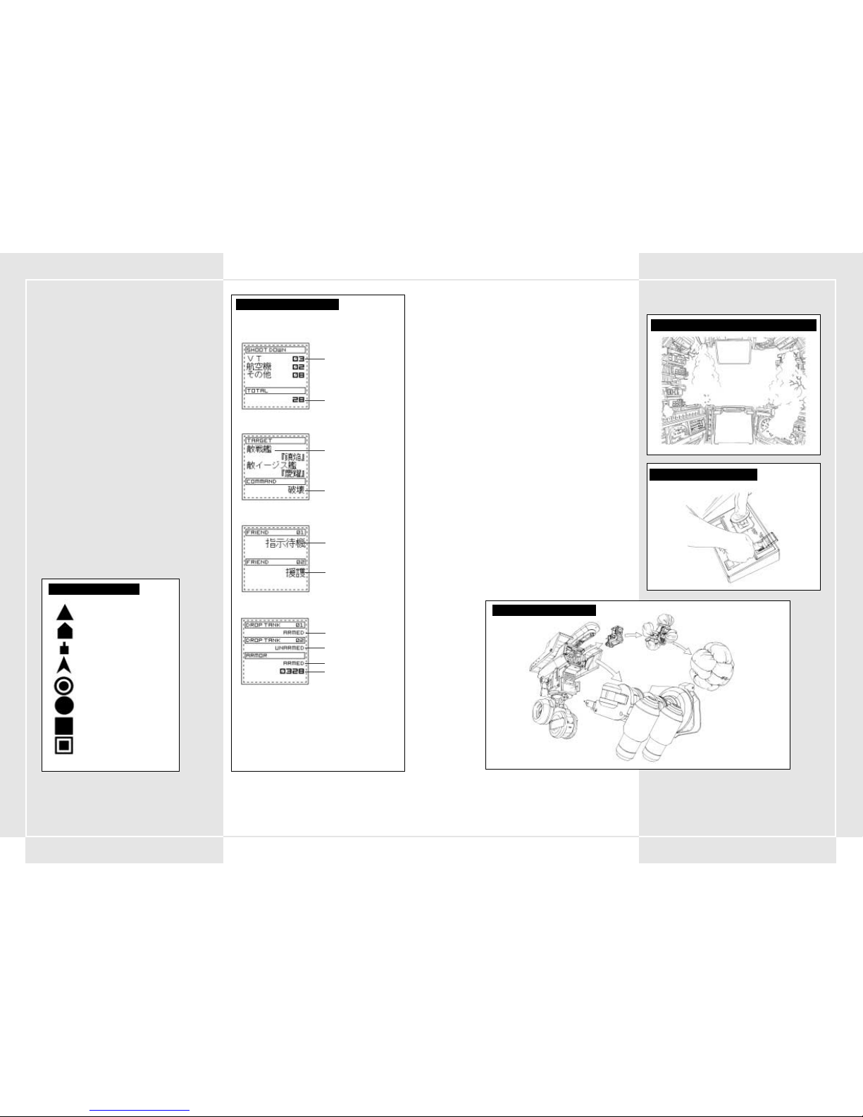
JCS (Complete Command System)
4-16 JCS SUMMARY
JCS is a system that uses war strategy data and the most recent
information to increase the effectiveness of the VT to its
maximum. Its main purpose is to supply the latest information
concerning the battlefield, friendly forces, the enemy and other
companies/ battalions. This system is designed to increase the
overall effectiveness of the VT in battle. VT pilots as well as
platoon commanders must be able to use it effectively.
The JCS uses a network that runs from the VT transport command
room to the command rooms of the various
companies/battalions, so it helps carry the latest news back and
forth to the right people. This system sends messages from VT
video monitors, recon satellites, and other command divisions,
and edits the data in real time in the Battalion Command Rooms.
Then it analyses the data and sends it to the various platoons.
The various data is sent to the VT over a communications
network and is displayed within the various monitors in the
cockpit. Thanks to this system, pilots can check the map, enemy
locations, and manage support fire for the forces.
COMPLETE COMMAND SYSTEM
NETWORK SUMMARY CHART
VT Transport Command Centre
VT
Recon Jet
Recon Satellite
Page 11
18 19
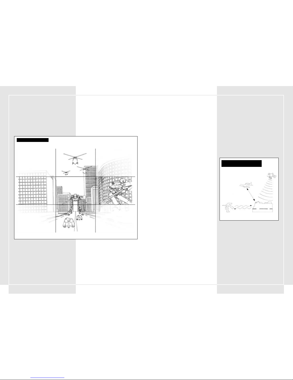
4-17 MULTI-MONITOR DISPLAY
The multi-monitor display in the upper area of the main monitor
is used to display information sent from the Master Command
Centre. The multi-monitor is not always displayed. You can toggle
its display on and off by pressing the multi-monitor open/close
button.
4-18 INFORMATION DISPLAYED IN THE MULTIMONITOR
The following information is shown on the multi-monitor.
1. War Map
Shows a 25 kilometre radius of the surrounding area. Use the
zoom in/out button to zoom the map to a maximum area of
5,000km radius.
2. Personal VT Information
Shows the current statistics and state of your VT. Use this to
check how much spare armour or fuel that you have.
3. Mission Objective
Shows information concerning the main objective for the
current mission. If there is a sudden change in the mission
then that information is displayed here. Pilots and especially
platoon commanders should ensure that they check this.
4. Platoon
Shows only the data of the platoon commander. You can
check to see what the current commands are to the other
members of that platoon.
5. Enemy Information
Shows information about the enemy VTs: their weapons’
firing distance, attack power, etc. Also displays data on
various support machines.
Ones VT
VT
Other land items (tanks, cannons)
Air forces (helicopter, bombers)
Estimated hit zone for a curved trajectory weapon
Bullets
Estimated hit area for your main weapon
Estimated hit area for your sub weapon
MAP MONITOR DISPLAY
MULTI-MONITOR DISPLAY
CHECKING NUMBER OF ENEMIES DESTROYED
Number and type of enemy destroyed
Total number of enemies destroyed
Main Objective
Order concerning main objective
MAIN OBJECTIVE SCREEN
Order wingman 1 is carrying out
Order wingman 2 is carrying out
WINGMAN’S STATUS
Fuel tank 1
Fuel tank 2
Add-on armour
Remaining number of points left
on add-on armour
PERSONAL VT STATUS
EMERGENCY PROCEDURES
4-19 EVACUATION SETUP
An evacuation feature has been added to the VT to protect the
pilot’s safety. If you continually take damage, if your resistance
armour is depleted (see section 2-5), or if your VT reaches
dangerous levels, then protect yourself by ejecting as soon as
possible. The protective gel layer surrounding the cockpit will
become the escape pod and a small rocket placed below the
escape pod will jettison you away.
4-20 EMERGENCY EJECT SWITCH
The emergency eject switch is located on the right side of the
console. It is surrounded by a black and yellow glass cover.
The switch is on the same side as the Start button, so be sure not
to press the Start button accidentally. When you press the
switch, your cockpit is fired out the back of your VT. As you are
ejected the gel block coating forms an airbag around your cockpit
on all sides to protect you from the shock of the landing.
4-21 EMERGENCY ESCAPE PROCEDURES IN
RIVERS OR SEAS
Because the VT is not 100% watertight or waterproof, it cannot
navigate in bodies of water deeper than 20 metres and will be
unable to move in those instances. If you fall into water deeper
than 20 metres, the water will begin seeping through the gel
coated cockpit, forcing you to eject. Ejecting while in water is the
same as on land. The gel coating will form an airbag lifting you
to the surface.
4-22 FIRE IN THE HULL
Whenever a fire breaks out in the hull, you must act quickly.
Flame thrower damage and getting shot too many times can start
a fire that does damage to the armour and weakens the resistance
armour of your VT. If the fire warning alarm goes off and the
cockpit warning lights are flashing, then check to see which area
the fire is in and press the fire extinguisher button on the
control panel.
EMERGENCY EJECT SWITCH
RESISTANCE ARMOUR REACHING CRITICAL MASS
PILOT EJECT PROCEDURE
Page 12

20 21
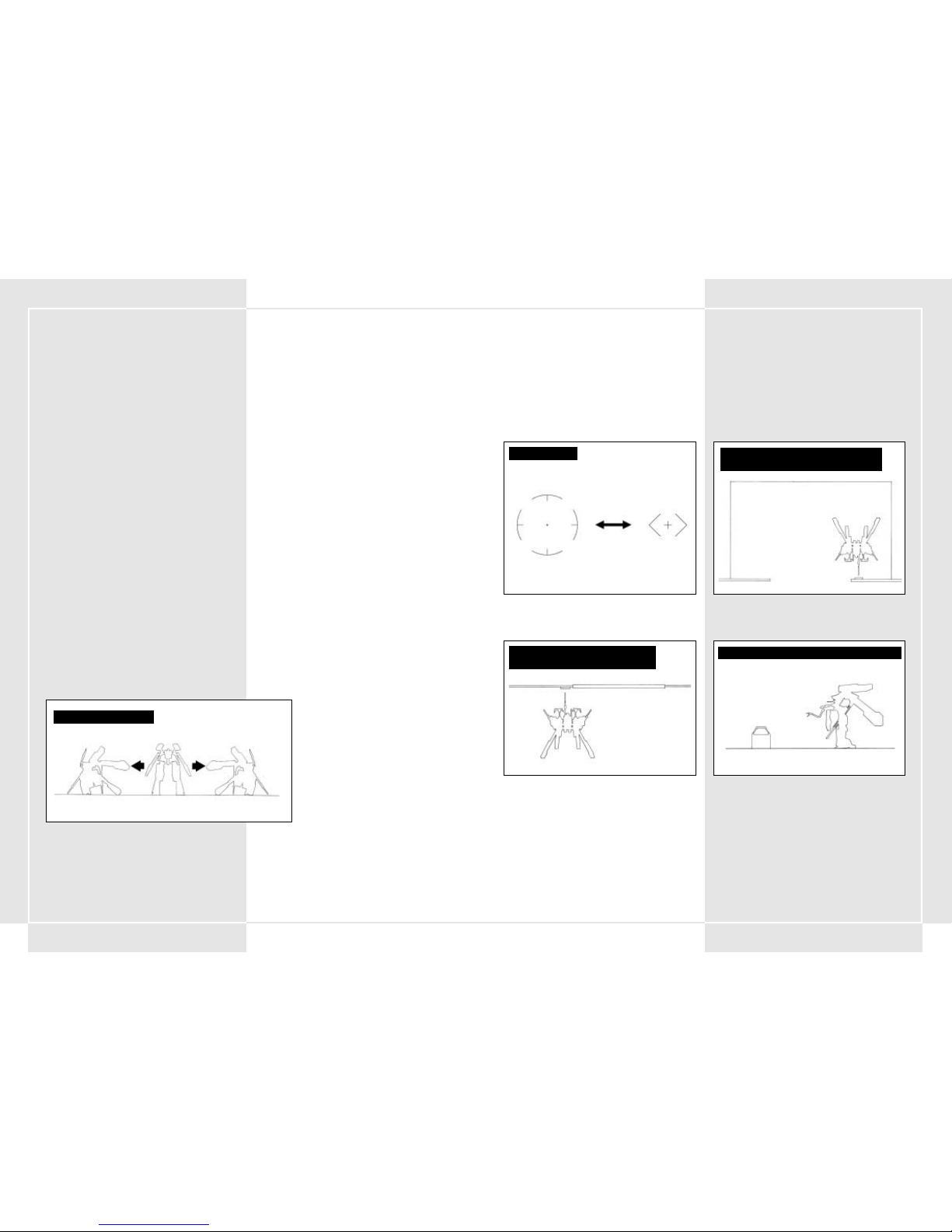
5-1 WEAPON TARGETING AND SHOOTING
Weapon targeting is performed by using the right targeting stick
to place the targeter over the enemy on the screen. The upper
body weapons are capable of moving independently and
therefore give the VT a maximum 180° targeting radius. After you
place the cursor over the enemy, you can fire your main weapon
by pressing the main weapon trigger or your sub weapon by
pressing the sub weapon trigger.
5-2 LOCK-ON FUNCTION
In the VT, a special lock-on feature automatically targets certain
enemies. Once the targeter begins flashing on screen, pressing
the lock-on button on the right targeting stick allows you to
lock-on. While locked-on, if you press either your main weapon
or sub weapon triggers you will automatically target the enemy.
You can unlock the lock-on by pressing the lock-on button again
when the targeted enemy is destroyed, or if the enemy slips off
your screen.
Note: Because the lock-on function was basically designed for
anti-VT use, any other targets besides the VT or enemy cannons
will not work with the lock-on feature.
5-3 CLOSE COMBAT TARGETING
Within the VT’s sub weapons are several close combat weapons.
The ALC205 plasma torch is a good example since it can only be
used on a VT, and is quite a special weapon. However, you must
be careful. If you use one of these weapons then your target will
be slightly different from normal and you will switch into close
combat mode. This targeting mode is useful for close fighting
with a quick enemy that is immediately in front of you. The
targeter will only work on items right in front of your VT. If you
press the sub weapon button while the enemy is right in front
of you, you will charge forward and strike with your plasma
torch.
SECTION 5. VT ATTACK
TARGETING RADIUS
TARGETING DISTANCE
180
°
SUB WEAPON TARGETING
Outside targeting range Within targeting range
MAIN WEAPON TARGETING
Outside targeting range Within targeting range
LOCK-ON
Possible lock-on Post lock-on
CURSORS IN NORMAL AND CLOSE-IN FIGHTING
Normal mode Close-in mode
5-4 FSS (Target Estimating Firing System)
The FSS is a firing system that was developed to analyse combat
data and movement patterns of enemy VTs
Pressing the FSS button on the targeting stick switches the firing
mode from normal to Target Estimating Firing System, allowing
you to automatically focus on the location where the enemy will
most likely go next. Pressing the FSS button again returns to
normal firing mode.
Note: The FSS is a new function of the 2nd generation OS and
therefore is not loaded on VTs with a first generation OS. The
estimation data on the enemy’s movement pattern is not perfect,
and if the opponent is well trained then it can perform moves
that the FSS is incapable of estimating. There are some
opponents, therefore, that the FSS will not be effective on.
5-5 FIRING RANGES OF DIFFERENT WEAPONS
Each weapon has a firing range. The pilot should have a firm
grasp of both the maximum and the most effective firing range for
each weapon. The effective firing range for each weapon is
displayed either to the left or right of the main monitor target
and is set by the artillery control system.
The main weapon’s prime target range is listed to the right of the
targeter. The sub weapon’s prime target range is listed to the left.
The prime target range for both weapons overlaps the targeter. If
the enemy goes out of a range, a message appears telling you that
the enemy is out of range.
5-6 NOTES ON FIRING WITHIN EFFECTIVE
TARGET RANGE
The effective target range was set up mainly to display the
effective target range on the main monitor. However it was
basically designed for anti-VT fighting. When you’re fighting an
opponent with less armour than the VT (such as a tank), there is
a good chance that shots will have enough power to kill some
enemies that are out of range. Also, the effective target range is
programmed based on thickness of the VT armour, as set by
Pacific Rim Organisation standards. Therefore if a target with
heavy armour is in the effective targeting range, there is the
chance that it will not take damage. Be careful.
WHEN USING THE PLASMA TORCH
High speed movement
FSS FIRING LINES
Position of locked target when you are firing
Position of locked target when bullet hits
Page 13
22 23
5-7 USING EFFECTIVE TARGET RANGE
One very important aspect of a VT battle is having equipment that
does more damage than the enemy’s and gives you the advantage
in a fight. This is particularly true when your effective targeting
range is farther then the other opponent’s, as you can then "outrange" them. If you have more range then the enemy, then you
only need to approach far enough to get a shot. If you have a
chance to destroy the enemy without taking damage, you should
use that opportunity to its best advantage. Don’t put your VT or
yourself in unnecessary danger.
5-8 LAND SUPPRESSION ATTACK
Weapons such as the grenade cannon, MLRS and napalm explode
near the surface of the ground and do damage to enemies within
a certain radius. Laying down this "suppression fire" can be a
very effective tactic for dealing with enemies grouped in a
cluster.
5-9 WEAPON CHANGE
One of the key areas where VTs surpass other units is in their
ability to equip a wide variety of different weapons. A VT can
carry 3 main weapons and 3 sub weapons. However, only one of
each can be fired at a time. Choose main and sub weapons by
pressing the weapon controls button.
5-10 RELOADING MAGAZINE WEAPONS
Some weapons in your arsenal use magazines. Whenever you
need to reload a magazine into the weapon, press the magazine
change button. Your remaining bullets and number of extra
magazines are listed on the control panel.
WEAPON CHANGE SYSTEM
GROUND SUPPRESSION FIRE
Effective range = 400mm
Effective range = 1000mm
Out of range = 1600mm
EFFECTIVE TARGETING RANGE
(270mm Rifle) (0-1500mm)
EFFECTIVE TARGETING RANGE (MK34
Rocket Cannon) (500-1000mm)
Effective range = 600mm
Out of range = 1600mm
Out of range = 300mm
6-1 IN GENERAL
This section explains the basic rules of VT movement on the
battlefield.
Movement is used to hide out of the enemy’s line of sight and to
avoid areas where potential enemies may lay. It should also be
used to avoid areas of concentrated enemy firepower. A pilot
could assume that the enemy will concentrate its VTs on terrain
that is easily manoeuvrable for the VTs, so it should be noted that
fighting in an area that VTs have a hard time adapting to could
actually be advantageous.
When moving through areas where your VT could easily get stuck,
you may need reinforcements from the engineering section.
6-2 USING WEATHER AND TOPOGRAPHY
On the battlefield you should always try to move effectively
though the weather and topography. It is more important to do
that than to worry about coming into contact with the enemy.
A VT, when compared to a walking machine or a tank, may not be
as easily affected by topography. But with its massive size it
stands out and is easily locatable by the enemy.
Try to make good use of the surrounded topography when you
are in a situation where you may come into contact with the
enemy. With the development of energy fields (ECM) in particular,
the importance of using the topography and to have a good line
of sight become all the more important. In these cases, estimating
enemy movement and dodging artillery are areas you must focus
on.
•Forest
Trees are better than anything else at hiding tall VTs. They
also make excellent obstacles for oncoming firepower.
•Exposed Land
There is no cover so you must move around as normal.
• Enclosed Roads/Valleys
Paths that you can move on are limited by valleys, where
possible enemy ambushes could lay in waiting. You must be
very careful here.
Be sure to check out both sides before you enter into one of
these areas. Also, be sure to check for possible land mines
that may have been planted on the path. Finally be careful
of curves in the road or areas that you cannot avoid by
taking detours. Be extremely careful whenever you cross
bridges.
• Rivers
At the present time, a VT’s water proofing/resistance is far
from sufficient. In tests of up to 10 metres of water, VT
movement was manageable. However, immersion in greater
depths leads to water penetration into the various joint
sections and damage to the VT. At 20 metres of water, the VT
breaks down and completely stops. It is essential that you
examine the depth of the water that you are crossing over or
through before proceeding.
SECTION 6. VT MOVEMENT
Page 14
2524
STEEL BATTALION CONTROLLER CONFIGURATION
Page 15

26 27
7-1 ORDERS
Basically speaking, battalions and companies give orders to
platoons. Orders are given via written messages, as well as
through speech. Most commonly, before every mission there will
be a briefing in which some of the following information will be
displayed:
• Mission objective
• Enemy information
• Friendly units situation
• Topography
• Battlefield state
• Estimated mission completion time
After that, officers of differing rank will help analyse the orders
and you will make a plan of attack for your platoon.
7-2 MISSION ANALYSIS
Once you receive a command from one of the high level
commanders (battalion/company), the platoon division
commander will analyse the mission based on key information.
The mission analysis includes:
•Mission breakdown
• Enemy information
• Topography
•Weapons that can be used in the current mission
• Necessary equipment and supplies
Before the strategy preparations end, you must request your VT
type and weapons as well as the necessary equipment to take.
You should also check your mission objectives again.
You should also make sure that other platoon members are
positively sure of their mission goals, and that they will not make
any mistakes during battle.
7-3 CHOOSING WEAPONS
A VT pilot must choose which weapons to take along in battle.
These weapons must be appropriate for the mission objectives.
You can carry 3 main weapons and 3 sub weapons, but you cannot
exceed the maximum weight allowance for your VT type when
choosing weapons. Note that even if you do not exceed the
maximum weight balance for the VT, carrying close to the
maximum allowed weight limit is in itself bad for your balancer
and can greatly reduce the VT’s performance.
7-4 SELECTION OF ADDITIONAL ARMOUR AND
SUB WEAPONS
Whenever you add extra armour onto your VT, you will
automatically be equipped with the sub weapon armoured
missiles. This will reduce the number of selectable sub-weapons
by one. Please make sure that with the armour attached you do
not exceed the maximum weight allowance.
7-5 CHOOSING YOUR VT
There are 3 types of VT that are distributed to platoons: Light,
Middle, and Heavy. You choose your VT based on the mission but
the actual decision is left to the pilot. Also, when participating in
an air drop mission, you can only choose the light type VT.
7-6 ATTACHING EXTRA FUEL TANKS AND
ARMOUR
Based on the mission, you may choose to add extra fuel tanks or
armour. However, additional armour can only be used on a
limited number of VTs. Also, be sure that the final total of your
armour, extra fuel and weapons does not exceed the maximum
weight allowance. To learn more about the relationship between
sub weapons and additional armour, read section 7-4.
7-7 SUPPLY REQUESTS
Before you go out to battle, the estimated number of bullets you
will use for that mission will be supplied to you. However, if you
run out of ammo in battle you will quickly need to get more. In
order to achieve smooth supply transfer you will need to have all
pilots estimate the number of extra rounds they think they will
use in battle and send in a supply order form to the
reinforcement battalion beforehand.
7-8 FIXED VT FOOD PROVISIONS
Since operation time for a VT is rather short, regular food
provisions are issued from the Provision Company. However,
since in some cases food cannot be issued, each VT is loaded with
an emergency food supply equivalent to 4 servings. In situations
where there is no other way, each ranked commander is
responsible for using these. After they are used, an upper level
commander should be told immediately, so that they can be
replenished.
7-9 BRINGING PERSONAL EFFECTS INTO THE
COCKPIT
There is a compartment for holding provisions inside the cockpit.
If the personal effect is capable of fitting into the compartment
space then it is possible to bring personal items into the cockpit.
However, carrying private items into the VT must be cleared
beforehand by an accompanying commander. Also, it is forbidden
to carry the operation manual, which is strictly confidential, into
the VT.
SECTION 7. PLATOON STRATEGY PREPARATIONS
8-1 SUMMARY
Communications has the important role of helping relate key
information, changing plans within groups, helping carry out
important orders, and assisting in the transfer of new orders and
information.
Every VT has a JARC-F522 radio for communications.
In the platoon commander’s VT there are 2 JARC-F522 radios or 1
JARC-F522 radio and 1 JARC-A232 radio. Try to pronounce clearly
when speaking over the radio and keep the conversation to the
point. Also, be careful of enemy listening devices and keep your
identity secret by using call signs whilst talking.
8-2 PRESET CHANNELS
Some channels are preset in the standard VT radio. This saves the
time it would take to tune into each of these channels, time that
you may not have in the heat of battle. You can have up to 5
preset channels for you VT radio.
8-3 RADIO COMMUNICATION PROCEDURES
Communication via the radio is carried out by selecting channels
using an antenna. Then press the communication button to
begin the transmission. Communication is fixed to 3 possible
choices. You cannot change what each of these choice buttons
does. The choices are as follows:
• Communication button 1 – Respond/call
• Communication button 2 – Repeat
• Communication button 3 – Supply request
SECTION 8. RADIO TRANSMISSIONS
1. Communication panel 1 (from the main battalion Argus) begins to flash.
This signals that a message from the main battalion is coming in.
2. Set the tuner on Communications Panel 1.
3. Press Communication Button 1 (respond/call) and open a connection.
"This is Oscar 3. Argus, go ahead."
The battalion head gives his message.
"This is Argus. Your division is in a bad spot! Disengage immediately!"
5. After you hear what was said, press Communication Button 1
(respond/call).
"Oscar 3. I copy that."
6. Finish the communication.
7. If you didn’t hear the message, press Communication Button 2 (repeat).
COMMUNICATIONS PROCEDURES
(example: order to retreat)
COCKPIT:
MAIN BATTALION COMMAND ROOM:
1. Communication panel 1 (from the main battalion Argus) begins to flash.
This signals that a message from the main battalion is coming in.
2. Set the tuner on Communications Panel 1.
3. Press Communication Button 1 (respond/call) and open a connection.
"This is Oscar 3. Argus, go ahead."
4. The battalion head gives his message.
"This is Argus. Your division is in a bad spot! Retreat immediately!"
5. After you hear what was said, press Communication Button 1 "
6. If you didn’t hear the message, press Communication Button 2 (repeat).
7. Finish the communication.
Communication panel 1 (from the main battalion Argus) begins to flash.
This signals that a message from the main battalion is coming in.
Set the tuner on Communications Panel 1.
Press Communication Button 1 (respond/call) and open a connection.
"This is Oscar 3. Argus, go ahead."
4. The battalion head gives his message.
"This is Argus. Your division is in a bad spot! Retreat immediately!"
After you hear what was said, press Communication Button 1 (respond/call).
"Oscar 3. I copy that."
If you did not hear the message, press Communication Button 2 (repeat).
Finish the communication.
Page 16
2928
COMMUNICATIONS PANEL CHANNEL SETTINGS
Comm Panel 1 Comm Panel 2 Comm Panel 3 Comm Panel 4 Comm Panel 5
MIS00
MIS01
MIS02
MIS03 Command Supply VT Commander
MIS04 Command Supply VT Commander
MIS05 Command Supply VT Commander
MIS06 Command Supply VT Commander
MIS07 Command Supply VT Commander
MIS08 Command Supply VT Commander
MIS09 Command Supply VT Commander
MIS10 Command Supply VT Commander
MIS11 Command Supply VT Commander
MIS12 Command Supply Wingman 1 Wingman 2 Wingman 1/2
MIS13 Command Supply Wingman 1 Wingman 2 Wingman 1/2
MIS14 Command Supply Wingman 1 Wingman 2 Wingman 1/2
MIS15 Command Supply Wingman 1 Wingman 2 Wingman 1/2
MIS16 Command Supply Wingman 1 Wingman 2 Wingman 1/2
MIS17 Command Supply Spy Division
MIS18 Command Supply Wingman 1 Wingman 2 Wingman 1/2
MIS19 Command Supply Wingman 1 Wingman 2 Wingman 1/2
MIS20 Command Supply
MIS21 Command Supply Wingman 1 Wingman 2 Wingman 1/2
MIS22 Command Supply Wingman 1 Wingman 2 Wingman 1/2
MIS23 Command Supply Wingman 1 Wingman 2 Wingman 1/2
8-4 SENDING A MESSAGE
1. Choose the person you will call by dialling their
channel on the tuner.
2. Press communication button 1 (call/respond)
to place the call.
3. The person you are calling will respond.
4. After making sure this is the correct person,
state your request.
5. The other person will check your request.
6. The call will end.
8-5 RECEIVING A MESSAGE
1. When a message comes in, your communication
panel will begin to flash. Turn the tuner to the
flashing channel. By doing this you can hear the
other person’s message.
2. Press communication button 1 (call/respond)
and respond to the message.
3. The other person will see that you responded
and state the message.
4. After you hear the message, press
communication button 1 (call/respond) to
finish the call.
8-6 REPEATING THE MESSAGE
If you did not catch what someone said in their
communication, press communication button 2 to
request that the person repeat the message. You can
make a request any time the communication panel is
flashing (indicating that the lines are open). Once
you press communication button 1, the
communication will end and the line will be closed.
CALL SIGN LIST (printed 2080)
Group Call Sign English Name Formal Name
Player(Platoon) Oscar 3 Oscar 3 7th Special Panzer Division, 34th Special Armoured Battalion, 6th Special Armoured Company, 1st Platoon 3rd VT
Commander Oscar 1 Oscar 1 7th Special Panzer Division, 34th Special Armoured Battalion, 6th Special Armoured Company, 1st Platoon 1st VT
Main Battalion Argus Argus 7th Special Panzer Division, 34th Special Armoured Main Battalion
Supply Wagonmaster Wagonmaster 7th Special Panzer Division, Reinforcement Supply Battalion
CALL SIGN LIST (printed 2082)
Player(Platoon) Xray 1 Xray 1 7th Special Panzer Division, 34th Special Armoured Battalion, 6th Special Armoured Company, 1st Platoon 1st VT
Wingman 1 Xray 2 Xray 2 7th Special Panzer Division, 34th Special Armoured Battalion, 6th Special Armoured Company, 1st Platoon 2nd VT
Wingman 2 Xray 3 Xray 3 7th Special Panzer Division, 34th Special Armoured Battalion, 6th Special Armoured Company, 1st Platoon 3r d VT
Main Battalion Argus Argus 7th Special Panzer Division, 34th Special Armoured Main Battalion
Supply Wagonmaster Wagonmaster 7th Special Panzer Division, Reinforcement Supply Battalion
Spy Blackwidow Blackwidow ??????????
COMMUNICATION BUTTONS (2082)
Comm Button 1 Comm Button 2 Comm Button 3 Comm Button 4 Comm Button 5
Call/Respond Repeat Supply Request
COMMUNICATION BUTTONS (2080)
Comm Button 1 Comm Button 2 Comm Button 3 Comm Button 4 Comm Button 5
Call/Respond Repeat Supply Request Backup Request
9-1 ACCEPTING SUPPLIES
Supplies are necessary for maintaining the power of the VT. Find
a location where you can re-supply yourself in battle. Resupplying during a battle is a regular and arduous task. During a
battle, try receiving supplies only when you have some cover or
late at night. Supplies for VTs are carried out via a supply
helicopter under the Supply Battalion of the Reinforcements
Division. Not only can you refuel and replenish your bullets, but
the supply helicopter can also bring new armour, additional
armour, and replacement parts for your VT. For smooth
supplying, be sure to issue your estimated supply request before
going out on your mission.
9-2 CLASSIFYING SUPPLIES
In order to make the issuing of supplies an easier task, they have
been separated into 5 major groups. With a few exceptions, the
majority of parts you will request before a battle will fit into the
following 3 groups.
These are issued as one order to each VT.
1. Type 1 supplies: Foodstuffs
2. Type 3 supplies: Liquids (oil, fuel, lubricant)
3. Type 5 supplies: Various bullets
Before going out to battle, each pilot must create a list of the
necessary supplies and get it approved by his commanding
officer.
9-3 SUPPLY VIA SUPPLY HELICOPTER
During battle, supplies to VTs are brought in via a supply
helicopter that operates under the Division Supply Battalion.
When you request supplies, the helicopter heads to the VT
location. Once it arrives, it begins to hover. The pilot must move
the VT below the helicopter. Then the transference of fuel and
bullets occurs. You can also transfer new armour and
replacement parts for your VT.
9-4 CHOICES AND CAUTIONS WHEN RECEIVING
SUPPLIES
Since it takes time to re-supply, there is a temporary amount of
time when both your VT and the supply helicopter are open to
attack. In order to prevent attack you must examine the
surroundings and be cautious of your environment. Try to set the
re-supply location at a site that has some cover and few visible
enemies. This is an important measure in preventing the
helicopter from being shot down before it can re-supply you.
9-5 OPENING OF SUPPLY ISSUANCE CENTRE
Sometimes due to battle circumstances or weather problems, the
supply helicopter cannot come to re-supply. In order to solve
these situations, a supply issuance centre has been set up behind
friendly force lines. The location of the supply issuance centre is
determined before a battle, and is set up using these guidelines:
1. It has an adequate amount of space to store necessary
supplies.
2. A favourable path connects the front lines with the back
lines.
3. It is hidden from enemy vision.
4. It has coverage from enemy firepower.
The Supply Issuance Centre is only set up in locations where the
front line has been fixed and there is an encampment covering
the area. Basically, it is a unique exception.
As a basic VT duty, you are expected to refuel using the supply
helicopter whenever possible.
SECTION 9. SUPPLY
VT HELICOPTER SUPPLY DIAGRAM
Normal flight
Re-supply is possible
Page 17
3130
10-1 LEADERSHIP DUTIES
A commander’s duty is to issue orders to his troops and fulfil his
designated mission. Commanders earn trust from their troops
through solid leadership and maintaining a strong, stable
division. Through this, they can increase their VT ability and
skills.
10-2 NECESSARY QUALITIES FOR A
COMMANDER
A commander has the responsibility to carry out his mission and
is responsible for his troops. A commander must have a good
knowledge of his troops, equipment, tactics, and strategy while
also being a top-notch VT pilot. However, the most important
responsibility of a commander is to earn his troops’ trust, provide
them with a role model, and proceed forward though his mission.
He must work to break though tough situations. In battle he must
maintain a strong will and sharp judgment. He must be quick and
decisive. If the commander hesitates in battle then his troops
become scared and lose their confidence. Because of this he must
carefully analyse the mission he has been assigned and be able to
plan independently.
10-3 ORDERS DURING BATTLE
The platoon commander must make each and every troop
understand his duty, his job and the rules of engagement. He
must command his troops so that they will be at their best. On
this basis he can issue simple orders. making battle strategies
simpler to carry out. The platoon commander must communicate
his orders via the preset communication button 4 or 5, as per
regulations. Doing this makes communications run more
smoothly. There are 4 different orders that can be preset. Based
on the battle plan, the platoon commander must choose 2 of
these orders.
These are the 4 key orders (from which the platoon commander
must choose 2):
1. Separate and Disengage
This is an order to separate from the fight. In the instance
that one of the platoon’s VTs is damaged, the platoon must
try to disengage as quickly as possible. The platoon leader
has a responsibility to carry out his order while protecting
his men. So he must do whatever possible to keep his men
alive.
2. Backup
The platoon troop must use his VT to back up another troop,
in instances such as while co-operating with other forces,
when contact with the enemy has been made, etc. This is to
increase the attack power of the platoon to its fullest. The
platoon commander thoroughly knows the rules and
regulations and has used them in practice and command. He
must raise the level of training for his troops as well.
3. Attack
This is an order to attack the main objective. The platoon
commander issues this order based on the circumstances.
The most important characteristic here is to be a role model
for the troops, but achieving the objective is the main goal
of the whole platoon. In instances where there are multiple
targets, issuing this command will make accomplishing the
mission easier.
4. Disperse
Whenever you sense the enemy coming you can issue an
order to have your troops disperse. This order can be
extremely helpful whenever the topography of the
battlefield makes it a necessity or when you have to search
large areas.
WHEN USING THE PLASMA TORCH
SECTION 10. LEADERSHIP
PLATOON ORDER: SEPARATE AND DISENGAGE
PLATOON ORDER: BACKUP
PLATOON ORDER: ATTACK
PLATOON ORDER: DISPERSE
Wingman 1
Wingman 2
Platoon Commander
Wingman 1
Wingman 2
Platoon Commander
Wingman 1
Wingman 2
Platoon Commander
Wingman 1
Wingman 2
Platoon Commander
Page 18
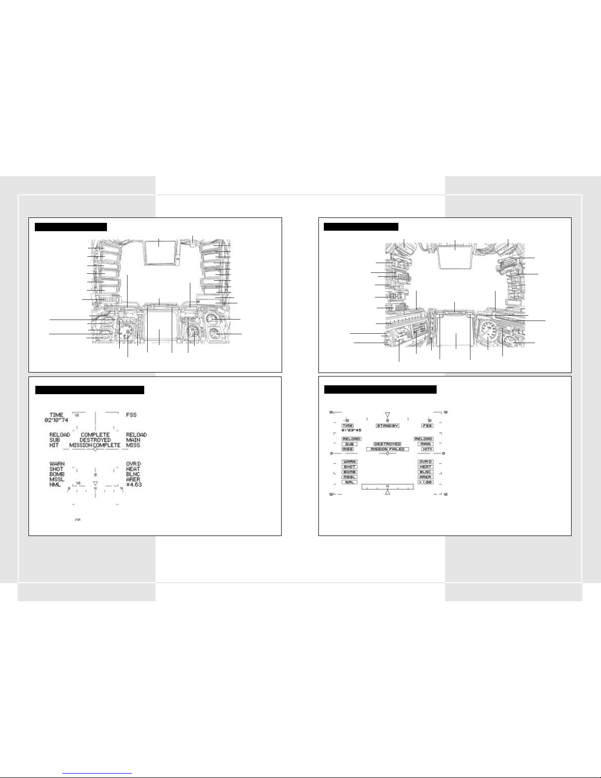
3332
WHEN USING THE PLASMA TORCH
TECHNICAL APPENDIX
COCKPIT: 1st GENERATION
Front obstacle warning lamp
Multi-monitor
Sub weapon 1 name
Sub weapon 1 remaining uses
Main weapon 1 name
Main weapon 1 remaining magazines
Main weapon 1 remaining bullets
Internal fire warning lamp
Right obstacle warning lamp
Left obstacle warning lamp
Main weapon 2 name
Main weapon 2 remaining magazines
Main weapon 2 remaining bullets
Main weapon 3 name
Main weapon 3 remaining magazines
Main weapon 3 remaining bullets
Comm lamps 1-5
Battery meter
Engine RPM meter
Speedometer
Main energy meter
Damage lamp
Sub-monitor
Shift lamp
Digital speedometer
Balancer limit overdrive
Tuner
Sub weapon 2 name
Sub weapon 2 remaining uses
Sub energy tank meter 1
Sub tank 1
attached or not
Sub tank 1 in use
Sub energy tank meter 2
Sub tank 2
attached or not
Sub tank 2 in use
Sub weapon 3 name
Sub weapon 3 remaining uses
Chaff remaining uses
WHEN USING THE PLASMA TORCH
COCKPIT: 2nd GENERATION
Front obstacle warning lamp
Balancer limit overdrive
Multi-monitor
Main weapon name
Main weapon remaining magazines
Main weapon remaining bullets
Internal fire warning lamp
Internal fire warning lamp
Right obstacle warning lamp
Left obstacle warning lamp
Comm lamps 1-5
Battery meter
Overdrive lamp
Engine RPM meter
Speedometer
Main energy meter
Damage gauge
Sub-monitor
Shift gauge
Digital speedometer
Tuner
Sub weapon 1 name
Sub weapon 1 remaining uses
Sub energy tank meter
Sub tank 1 in use
Sub tank 1
availability
Sub tank 2 in use
Sub tank 2
availability
Chaff remaining uses
MAIN MONITOR DISPLAY: 2nd GENERATION
TIME . . . . . . . . . . . . . . . . . . . . . . . . . Remaining time
FSS . . . . . . . . . . . . . . . . . . . . . . . . . . Shows your FSS system is operating
SUB . . . . . . . . . . . . . . . . . . . . . . . . . . Sub weapon info
RELOAD – You are in the middle of reloading
HIT/MISS – You hit or missed with your sub weapon
SUPPLY INFO . . . . . . . . . . . . . . . . . . . . STAND BY – Preparing to supply
REFUEL – Refuelling
COMPLETE – Refuelling has finished
DESTROYED . . . . . . . . . . . . . . . . . . . . . An enemy has been destroyed
MISSION COMPLETE . . . . . . . . . . . . . . . . Shows how much of the mission has been completed
MAIN . . . . . . . . . . . . . . . . . . . . . . . . . Main weapon info
RELOAD – You are in the middle of reloading
HIT/MISS – You hit or missed with your main weapon
WARN . . . . . . . . . . . . . . . . . . . . . . . . . Warns that the enemy is locked onto your VT
SHOT . . . . . . . . . . . . . . . . . . . . . . . . . Shows the enemy has fired a non-guided weapon at you
BOMB . . . . . . . . . . . . . . . . . . . . . . . . . Warning that curved trajectory bombs are coming
MSSL . . . . . . . . . . . . . . . . . . . . . . . . . Warning that a guided missile is coming
NML . . . . . . . . . . . . . . . . . . . . . . . . . . Shows normal operation (non-overdrive)
OVRD . . . . . . . . . . . . . . . . . . . . . . . . . Shows that you are in overdrive
HEAT . . . . . . . . . . . . . . . . . . . . . . . . . Shows that the battery has overheated
BLNC . . . . . . . . . . . . . . . . . . . . . . . . . Shows that the balancer is reaching critical mass
AREA . . . . . . . . . . . . . . . . . . . . . . . . . Shows you are leaving the designated battlefield
x 1.00 . . . . . . . . . . . . . . . . . . . . . . . . . Main camera’s magnification ratio
ANGLE OF DEPRESSION/ELEVATION . . . . . . Shows the camera angle
COMPASS . . . . . . . . . . . . . . . . . . . . . . . Shows you the direction in which you are heading
MAIN MONITOR DISPLAY: 1st GENERATION
TIME . . . . . . . . . . . . . . . . . . . . . . . . . Remaining time
FSS . . . . . . . . . . . . . . . . . . . . . . . . . . . Shows your FSS system is operating
SUB . . . . . . . . . . . . . . . . . . . . . . . . . . Sub weapon info
RELOAD – You are in the middle of reloading
HIT/MISS – You hit or missed with your sub weapon
SUPPLY INFO . . . . . . . . . . . . . . . . . . . . STAND BY – Preparing to supply
REFUEL – Refuelling
COMPLETE – Refuelling has finished
DESTROYED . . . . . . . . . . . . . . . . . . . . . An enemy has been destroyed
MISSION COMPLETE . . . . . . . . . . . . . . . . Shows how much of the mission has been completed
MAIN . . . . . . . . . . . . . . . . . . . . . . . . . Main weapon info
RELOAD – You are in the middle of reloading
HIT/MISS – You hit or missed with your main weapon
WARN . . . . . . . . . . . . . . . . . . . . . . . . . Warns that the enemy is locked onto your VT
SHOT . . . . . . . . . . . . . . . . . . . . . . . . . Shows the enemy has fired a non-guided weapon at you
BOMB . . . . . . . . . . . . . . . . . . . . . . . . . Warning that curved trajectory bombs are coming
MSSL . . . . . . . . . . . . . . . . . . . . . . . . . Warning that a guided missile is coming
NML . . . . . . . . . . . . . . . . . . . . . . . . . . Shows normal operation (non-overdrive)
OVRD . . . . . . . . . . . . . . . . . . . . . . . . . Shows that you are in overdrive
HEAT . . . . . . . . . . . . . . . . . . . . . . . . . Shows that the battery has overheated
BLNC . . . . . . . . . . . . . . . . . . . . . . . . . Shows that the balancer is reaching critical mass
AREA . . . . . . . . . . . . . . . . . . . . . . . . . Shows you are leaving the designated battlefield
4.63 . . . . . . . . . . . . . . . . . . . . . . . . . . Main camera’s magnification ratio
ANGLE OF DEPRESSION/ELEVATION . . . . . . Shows the camera angle
COMPASS . . . . . . . . . . . . . . . . . . . . . . . Shows you the direction in which you are heading
Page 19
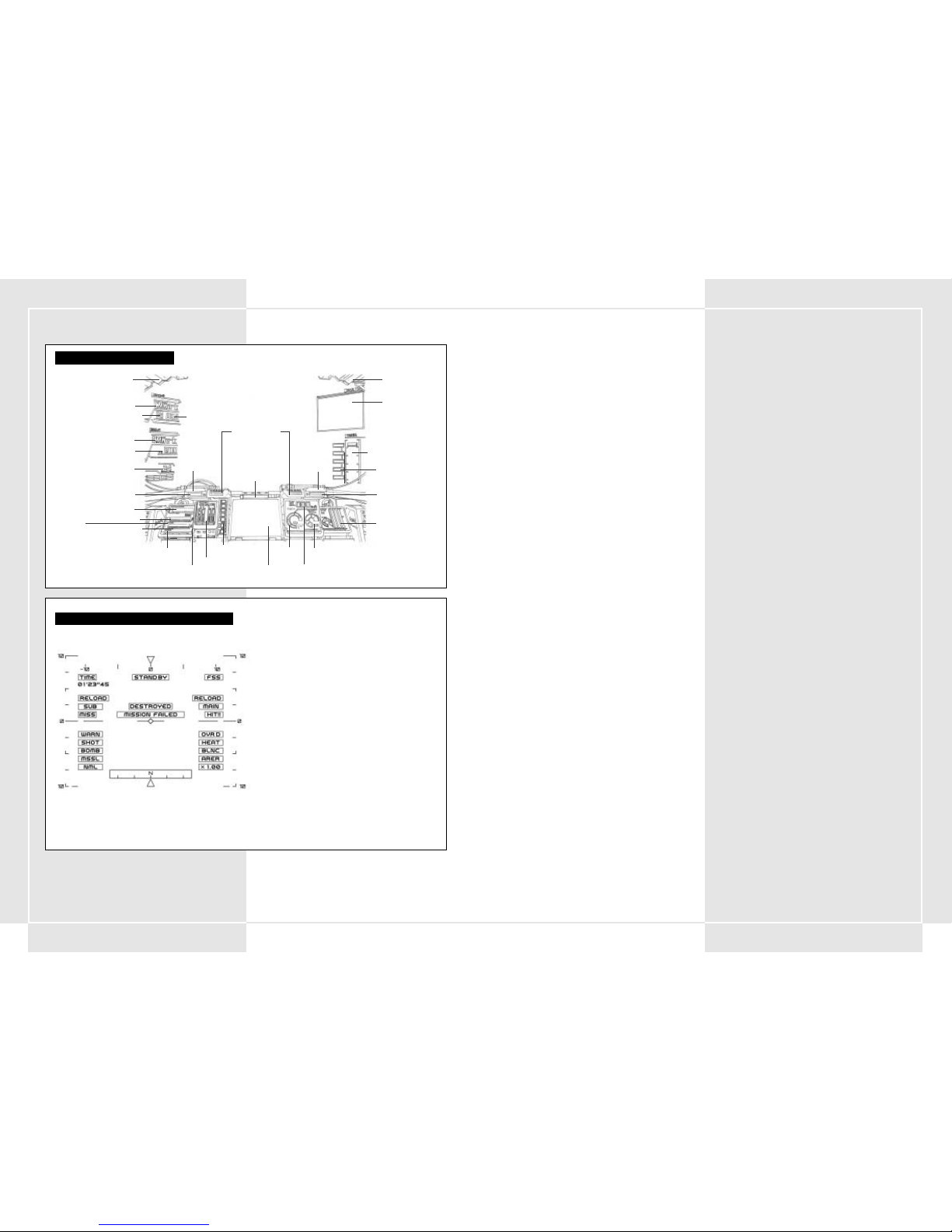
34
LIMITED WARRANTY FOR YOUR COPY OF XBOX GAME SOFTWARE
(“GAME”)
Warranty. Microsoft Corporation (“Microsoft”) warrants that this Game
will perform substantially as described in the accompanying manual for
a period of 90 days from the date of first purchase. This limited warranty
is void if any difficulties with the Game are related to accident, abuse,
virus or misapplication.
Microsoft does not make any other warranty or promise about the
Game affected by Microsoft’s limited warranty.
Your remedies.If you discover a problem with the Game covered by this
warranty within the 90 day period, return it to your retailer along with a
copy of the original sales receipt. Your retailer will, at its option, (a)
repair or replace the Game, free of charge, or (b) return the price paid.
Any replacement Game will be warranted for the remainder of the
original warranty period or 30 days from receipt, whichever is longer. To
the extent that you could have avoided damages by taking reasonable
care, Microsoft will not be liable for such damages.
Statutory rights. You may have statutory rights against your retailer
which are not
IF YOU DID NOT PURCHASE THE GAME FOR YOUR PERSONAL USE
(THAT IS, IF YOU ARE NOT DEALING AS A CONSUMER)
The following terms apply to the maximum extent permitted by
applicable law.
No other warranties. Microsoft and its suppliers disclaim all other
warranties and conditions, either express or implied, with respect to
the Game and the accompanying manual.
Limitation of liability. Neither Microsoft nor its suppliers shall be liable
for any damages howsoever caused arising out of or in any way related
to the use of or inability to use the Game, even if Microsoft or any
supplier has been advised of the possibility of such damages. In any
case, Microsoft’s and its suppliers’ entire liability is limited to the
amount actually paid by you for the Game.
For questions regarding this warranty contact your retailer or Microsoft
at:
Microsoft Ireland Operations Limited
Sandyford Industrial Estate
Blackthorn Road
Dublin 18
Ireland
Information in this document, including URL and other Internet Web site references, is
subject to change without notice. Unless otherwise noted, the example companies,
organizations, products, people and events depicted herein are fictitious and no
association with any real company, organization, product, person or event is intended or
should be inferred. Complying with all applicable copyright laws is the responsibility of the
user. Without limiting the rights under copyright, no part of this document may be
reproduced, stored in or introduced into a retrieval system, or transmitted in any form or
by any means (electronic, mechanical, photocopying, recording, or otherwise), or for any
purpose, without the express written permission of Microsoft Corporation.
Microsoft may have patents, patent applications, trademarks, copyrights, or other
intellectual property rights covering subject matter in this document. Except as expressly
provided in any written license agreement from Microsoft, the furnishing of this document
does not give you any license to these patents, trademarks, copyrights, or other
intellectual property.
© 2003, Microsoft Corporation. All rights reserved.
Microsoft, Xbox, and the Xbox logos are either registered trademarks or trademarks of
Microsoft Corporation in the United States and/or other countries.
Manufactured under license from Dolby Laboratories.
WHEN USING THE PLASMA TORCH
COCKPIT: 3rd GENERATION
Front obstacle
warning lamp
Balancer limit overdrive
Multi-monitor
Main weapon name
Main weapon remaining magazines
Main weapon remaining bullets
Internal fire warning lamp
Internal fire warning lamp
Right obstacle
warning lamp
Left obstacle
warning lamp
Comm lamps 1-5
Battery meter
Overdrive lamp
Overdrive lamp
Engine RPM meter
Speedometer
Main energy meter
Damage gauge
Sub-monitor
Shift gauge
Digital speedometer
Tuner
Sub weapon 1 name
Sub weapon 1 remaining uses
Sub energy tank meter 1
Sub tank 1
availability
Sub energy tank meter 2
Sub tank 2
availability
Chaff remaining uses
MAIN MONITOR DISPLAY: 3rd GENERATION
TIME . . . . . . . . . . . . . . . . . . . . . . . . . Remaining time
FSS . . . . . . . . . . . . . . . . . . . . . . . . . . . Shows your FSS system is operating
SUB . . . . . . . . . . . . . . . . . . . . . . . . . . Sub weapon info
RELOAD – You are in the middle of reloading
HIT/MISS – You hit or missed with your sub weapon
SUPPLY INFO . . . . . . . . . . . . . . . . . . . . STAND BY – Preparing to supply
REFUEL – Refuelling
COMPLETE – Refuelling has finished
DESTROYED . . . . . . . . . . . . . . . . . . . . . An enemy has been destroyed
MISSION COMPLETE . . . . . . . . . . . . . . . . Shows how much of the mission has been completed
MAIN . . . . . . . . . . . . . . . . . . . . . . . . . Main weapon info
RELOAD – You are in the middle of reloading
HIT/MISS – You hit or missed with your main weapon
WARN . . . . . . . . . . . . . . . . . . . . . . . . . Warns that the enemy is locked onto your VT
SHOT . . . . . . . . . . . . . . . . . . . . . . . . . Shows the enemy has fired a non-guided weapon at you
BOMB . . . . . . . . . . . . . . . . . . . . . . . . . Warning that curved trajectory bombs are coming
MSSL . . . . . . . . . . . . . . . . . . . . . . . . . Warning that a guided missile is coming
NML . . . . . . . . . . . . . . . . . . . . . . . . . . Shows normal operation (non-overdrive)
OVRD . . . . . . . . . . . . . . . . . . . . . . . . . Shows that you are in overdrive
HEAT . . . . . . . . . . . . . . . . . . . . . . . . . Shows that the battery has overheated
BLNC . . . . . . . . . . . . . . . . . . . . . . . . . Shows that the balancer is reaching critical mass
AREA . . . . . . . . . . . . . . . . . . . . . . . . . Shows you are leaving the designated battlefield
x 1.00 . . . . . . . . . . . . . . . . . . . . . . . . . Main camera’s magnification ratio
ANGLE OF DEPRESSION/ELEVATION . . . . . . Shows the camera angle
COMPASS . . . . . . . . . . . . . . . . . . . . . . . Shows you the direction in which you are heading
35
Page 20

3736
CONFIGURATION DU POSTE DE CONTRÔLE . . . . . . . . . . . . . . . . . . . . . . . . 38
Précautions . . . . . . . . . . . . . . . . . . . . . . . . . . . . . . . . . . . . . . . . . . . . 38
Dépannage . . . . . . . . . . . . . . . . . . . . . . . . . . . . . . . . . . . . . . . . . . . . 38
Montage de l'unité droite . . . . . . . . . . . . . . . . . . . . . . . . . . . . . . . . . 38
Montage de l'unité gauche . . . . . . . . . . . . . . . . . . . . . . . . . . . . . . . . 38
SECTION 1. CONCEPT DU VT ET DIVISION SPÉCIALE DE PANZERS . . . . . . . . 40
1-1 Concept du VT . . . . . . . . . . . . . . . . . . . . . . . . . . . . . . . . . . . . . . . 40
1-2 Principes du VT à usage militaire . . . . . . . . . . . . . . . . . . . . . . . . 40
1-3 Fonctions de l'unité blindée spéciale . . . . . . . . . . . . . . . . . . . . . 40
1-4 Formation d'une division spéciale de Panzers . . . . . . . . . . . . . . 40
1-5 Fonctionnement de la section VT . . . . . . . . . . . . . . . . . . . . . . . . 40
SECTION 2. RÉSUMÉ DES VT . . . . . . . . . . . . . . . . . . . . . . . . . . . . . . . . . . . . . 41
2-1 Pièces élémentaires du VT . . . . . . . . . . . . . . . . . . . . . . . . . . . . . . 41
2-2 Fonctionnement du VT . . . . . . . . . . . . . . . . . . . . . . . . . . . . . . . . . 41
2-3 Types de VT . . . . . . . . . . . . . . . . . . . . . . . . . . . . . . . . . . . . . . . . . 42
2-4 Déplacement . . . . . . . . . . . . . . . . . . . . . . . . . . . . . . . . . . . . . . . . 42
2-5 Réservoirs de carburant et réservoirs de rechange . . . . . . . . . . 42
2-6 Consommation de carburant et temps de déplacement estimé . 42
2-7 Blindage défensif . . . . . . . . . . . . . . . . . . . . . . . . . . . . . . . . . . . . . 42
2-8 Arme principale et arme secondaire . . . . . . . . . . . . . . . . . . . . . 42
2-9 Tolérance de poids d'armement maximale . . . . . . . . . . . . . . . . . 42
2-10 Armes chargées sur le VT . . . . . . . . . . . . . . . . . . . . . . . . . . . . . . 43
2-11 Visée des armes à trajectoire incurvée sur la carte de guerre . . 48
2-12 Fusée à retardement . . . . . . . . . . . . . . . . . . . . . . . . . . . . . . . . . 48
2-13 Leurres . . . . . . . . . . . . . . . . . . . . . . . . . . . . . . . . . . . . . . . . . . . . 48
SECTION 3. FONCTIONS SPÉCIALES
DU COOS DE 2 ÈME GÉNÉRATION . . . . . . . . . . . . . . . . . . . . . . . . . . . . . . . . 48
3-1 Apports du COOS de 2 ème génération . . . . . . . . . . . . . . . . . . . . . . . . . 48
3-2 FSS (système de tir à estimation de cible) . . . . . . . . . . . . . . . . . . 48
3-3 Vitesse surmultipliée . . . . . . . . . . . . . . . . . . . . . . . . . . . . . . . . . . 48
3-4 Furtivité . . . . . . . . . . . . . . . . . . . . . . . . . . . . . . . . . . . . . . . . . . . . 48
3-5 Armes guidées . . . . . . . . . . . . . . . . . . . . . . . . . . . . . . . . . . . . . . . 48
SECTION 4. COMMANDES DU VT . . . . . . . . . . . . . . . . . . . . . . . . . . . . . . . . 49
4-1 Séquence de démarrage . . . . . . . . . . . . . . . . . . . . . . . . . . . . . . . 49
4-2 Calage du moteur au démarrage du VT . . . . . . . . . . . . . . . . . . . 49
Commandes de base . . . . . . . . . . . . . . . . . . . . . . . . . . . . . . . . . . . . . 50
4-3 Se déplacer et s'arrêter . . . . . . . . . . . . . . . . . . . . . . . . . . . . . . . . 50
4-4 Accélération et décélération . . . . . . . . . . . . . . . . . . . . . . . . . . . . 50
4-5 Rotation . . . . . . . . . . . . . . . . . . . . . . . . . . . . . . . . . . . . . . . . . . . 50
4-6 Surmultipliée . . . . . . . . . . . . . . . . . . . . . . . . . . . . . . . . . . . . . . . 50
4-7 Glissement latéral . . . . . . . . . . . . . . . . . . . . . . . . . . . . . . . . . . . . 50
4-8 Limites fonctionnelles du glissement latéral . . . . . . . . . . . . . . . 50
4-9 Régulateur d'inclinaison en glissement latéral . . . . . . . . . . . . . . 50
4-10 Coupe-circuit . . . . . . . . . . . . . . . . . . . . . . . . . . . . . . . . . . . . . . . 50
4-11 Commandes du manipulateur . . . . . . . . . . . . . . . . . . . . . . . . . . . 51
Moniteur du VT . . . . . . . . . . . . . . . . . . . . . . . . . . . . . . . . . . . . . . . . . 52
4-12 Changement de la caméra principale . . . . . . . . . . . . . . . . . . . . . 52
4-13 Poussière et boue sur la caméra principale . . . . . . . . . . . . . . . . 52
4-14 Fonctions du moniteur secondaire . . . . . . . . . . . . . . . . . . . . . . 53
4-15 Équipement de vision de nuit . . . . . . . . . . . . . . . . . . . . . . . . . . 53
JCS (système de commande complet) . . . . . . . . . . . . . . . . . . . . . . . . 53
4-16 Résumé du JCS . . . . . . . . . . . . . . . . . . . . . . . . . . . . . . . . . . . . . . 53
4-17 Affichage multi-moniteur . . . . . . . . . . . . . . . . . . . . . . . . . . . . . . 54
4-18 Informations affichées sur le multi-moniteur . . . . . . . . . . . . . . 54
Procédures d'urgence . . . . . . . . . . . . . . . . . . . . . . . . . . . . . . . . . . . . . . . . 55
4-19 Préparation à l'évacuation . . . . . . . . . . . . . . . . . . . . . . . . . . . . . 55
4-20 Bouton d'éjection d'urgence . . . . . . . . . . . . . . . . . . . . . . . . . . . 55
4-21 Procédures d'éjection d'urgence en rivière ou en mer . . . . . . . 55
4-22 Feu dans la carlingue . . . . . . . . . . . . . . . . . . . . . . . . . . . . . . . . . 55
SECTION 5. ATTAQUE DU VT . . . . . . . . . . . . . . . . . . . . . . . . . . . . . . . . . . . . 56
5-1 Visée et tir . . . . . . . . . . . . . . . . . . . . . . . . . . . . . . . . . . . . . . . . . . 56
5-2 Fonction de verrouillage . . . . . . . . . . . . . . . . . . . . . . . . . . . . . . . 56
5-3 Visée en combat rapproché . . . . . . . . . . . . . . . . . . . . . . . . . . . . 56
5-4 FSS (système de tir à estimation de cible) . . . . . . . . . . . . . . . . . . 57
5-5 Portées de tir de différentes armes . . . . . . . . . . . . . . . . . . . . . . . 57
5-6 Notes sur le tir à portée de tir effective . . . . . . . . . . . . . . . . . . . 57
5-7 Utilisation de la portée de tir effective . . . . . . . . . . . . . . . . . . . . 58
5-8 Attaque de suppression terrestre . . . . . . . . . . . . . . . . . . . . . . . . 58
5-9 Changement d'arme . . . . . . . . . . . . . . . . . . . . . . . . . . . . . . . . . . 58
5-10 Armes à chargeur . . . . . . . . . . . . . . . . . . . . . . . . . . . . . . . . . . . . 58
SECTION 6. DÉPLACEMENT DU VT . . . . . . . . . . . . . . . . . . . . . . . . . . . . . . . 59
6-1 En général . . . . . . . . . . . . . . . . . . . . . . . . . . . . . . . . . . . . . . . . . . 59
6-2 Utilisation de la météo et de la topographie . . . . . . . . . . . . . . . 59
CONFIGURATION DU POSTE DE CONTRÔLE STEEL BATTALION . . . . . . . . . 60
SECTION 7. PRÉPARATIONS DE LA STRATÉGIE DE LA SECTION . . . . . . . . . . 62
7-1 Ordres . . . . . . . . . . . . . . . . . . . . . . . . . . . . . . . . . . . . . . . . . . . . . 62
7-2 Analyse de la mission . . . . . . . . . . . . . . . . . . . . . . . . . . . . . . . . . 62
7-3 Choix des armes . . . . . . . . . . . . . . . . . . . . . . . . . . . . . . . . . . . . . 62
7-4 Sélection d'armes et de blindages supplémentaires . . . . . . . . . . 62
7-5 Choix du VT . . . . . . . . . . . . . . . . . . . . . . . . . . . . . . . . . . . . . . . . . 62
7-6 Ajout de réservoirs et de blindages supplémentaires . . . . . . . . . 62
7-7 Demandes de ravitaillement . . . . . . . . . . . . . . . . . . . . . . . . . . . . 62
7-8 Provisions alimentaires fixes des VT . . . . . . . . . . . . . . . . . . . . . . 62
7-9 Effets personnels dans le cockpit . . . . . . . . . . . . . . . . . . . . . . . . 62
SECTION 8. TRANSMISSIONS RADIO
8-1 Résumé . . . . . . . . . . . . . . . . . . . . . . . . . . . . . . . . . . . . . . . . . . . . 62
8-2 Canaux prédéfinis . . . . . . . . . . . . . . . . . . . . . . . . . . . . . . . . . . . . 62
8-3 Procédures de communication radio . . . . . . . . . . . . . . . . . . . . . 62
8-4 Envoi d'un message . . . . . . . . . . . . . . . . . . . . . . . . . . . . . . . . . . 64
8-5 Réception d'un message . . . . . . . . . . . . . . . . . . . . . . . . . . . . . . . 64
8-6 Répétition du message . . . . . . . . . . . . . . . . . . . . . . . . . . . . . . . . 64
SECTION 9. RAVITAILLEMENT . . . . . . . . . . . . . . . . . . . . . . . . . . . . . . . . . . . 65
9-1 Accepter les ravitaillements . . . . . . . . . . . . . . . . . . . . . . . . . . . . 65
9-2 Classification des équipements . . . . . . . . . . . . . . . . . . . . . . . . . . 65
9-3 Ravitaillement par hélicoptère . . . . . . . . . . . . . . . . . . . . . . . . . . 65
9-4 Choix et précautions lors de la réception des équipements . . . 65
9-5 Ouverture du centre de ravitaillement . . . . . . . . . . . . . . . . . . . . 65
SECTION 10. COMMANDEMENT . . . . . . . . . . . . . . . . . . . . . . . . . . . . . . . . . 66
10-1 Devoirs du commandant . . . . . . . . . . . . . . . . . . . . . . . . . . . . . . 66
10-2 Qualités nécessaires à un commandant . . . . . . . . . . . . . . . . . . 66
10-3 Ordres en cours de bataille . . . . . . . . . . . . . . . . . . . . . . . . . . . . 66
ANNEXE TECHNIQUE . . . . . . . . . . . . . . . . . . . . . . . . . . . . . . . . . . . . . . . . . 68
Cockpit : 1 ère génération . . . . . . . . . . . . . . . . . . . . . . . . . . . . . . . . . 68
Moniteur principal : 1 ère génération . . . . . . . . . . . . . . . . . . . . . . . . 68
Cockpit : 2 ème génération . . . . . . . . . . . . . . . . . . . . . . . . . . . . . . . 69
Moniteur principal : 2 ème génération . . . . . . . . . . . . . . . . . . . . . . 69
Cockpit : 3 ème génération . . . . . . . . . . . . . . . . . . . . . . . . . . . . . . . . 70
Moniteur principal : 3 ème génération . . . . . . . . . . . . . . . . . . . . . . . 70
Garantie . . . . . . . . . . . . . . . . . . . . . . . . . . . . . . . . . . . . . . . . . . . . . 71
Support client . . . . . . . . . . . . . . . . . . . . . . . . . . . . . . . . . . . . . . . . 181
FRANÇAIS
AVANT DE JOUER
Merci d'avoir choisi STEEL BATTALION. Prenez soin de lire tous
les manuels d'instruction avant de commencer à jouer. Après
avoir lu les manuels, conservez-les à portée de main, dans un
endroit sûr, afin de pouvoir les consulter facilement et
rapidement.
AVERTISSEMENTS
• Entreposez la console et ses composants hors de portée des
enfants.
• N'ouvrez pas et ne modifiez pas l'unité ou ses composants.
• Ne versez aucun liquide sur l'unité ou ses composants.
• Entreposez l'unité et ses composants dans un endroit sec et
non poussiéreux.
• En cas de problème de fonctionnement, cessez
immédiatement de jouer.
TABLE DES MATIÈRES
INFORMATIONS SUR LA SÉCURITÉ
À propos des crises d'épilepsie liées à la
photosensibilité
Pour un très faible pourcentage de personnes, l'exposition à
certaines images, notamment aux lueurs ou motifs clignotants
pouvant apparaître dans les jeux vidéo, risque de provoquer
une crise d’épilepsie liée à la photosensibilité, même chez des
personnes sans antécédent épileptique.
Les symptômes de ces crises peuvent varier ; ils comprennent
généralement des étourdissements, une altération de la vision,
des mouvements convulsifs des yeux ou du visage, la crispation
ou le tremblement des bras ou des jambes, une désorientation,
une confusion ou une perte de connaissance momentanée. Ces
crises peuvent également provoquer une perte de connaissance
ou des convulsions pouvant engendrer des blessures dues à une
chute sur le sol ou à un choc avec des objets avoisinants.
Cessez immédiatement de jouer et consultez un médecin, si
vous ressentez de tels symptômes. Il est conseillé aux parents
de surveiller leurs enfants et de leur poser des questions
concernant les symptômes ci-dessus ; les enfants et les
adolescents sont effectivement plus sujets à ce genre de crise
que les adultes.
Pour réduire le risque d'une crise d'épilepsie liée à la
photosensibilité, il est préférable de s'asseoir à un
emplacement éloigné de l'écran du téléviseur, d'utiliser un
écran de petite taille, de jouer dans une pièce bien éclairée et
d'éviter de jouer en cas d'envie de dormir ou de fatigue.
Si vous, ou un membre de votre famille, avez des antécédents
de crises d'épilepsie, consultez un médecin avant de jouer.
Autres informations importantes sur la santé et la sécurité
Le manuel d'instructions Xbox contient des informations
importantes en matière de santé et de sécurité qui doivent être
lues et bien comprises avant d'utiliser ce logiciel.
Comment éviter d'endommager votre téléviseur
Vous ne devez pas utiliser certains téléviseurs. En effet,
certains d’entre eux, particulièrement ceux à projection
frontale ou par transparence, peuvent être endommagés si vous
les utilisez pour jouer à certains jeux vidéo, notamment les jeux
Xbox. Des images statiques présentées pendant le cours normal
du jeu risquent de se fondre avec l'écran, ce qui provoque
l'apparition définitive d'une ombre permanente de l'image
statique, même lorsque vous ne jouez pas aux jeux vidéo. Un
endommagement similaire risque de se produire à partir des
images statiques créées lorsque vous interrompez ou mettez en
pause un jeu vidéo. Reportez-vous au manuel d'utilisation de
votre téléviseur pour déterminer s'il est possible de jouer à des
jeux vidéo en toute sécurité sur votre poste. Si vous ne
parvenez pas à trouver ces informations dans le manuel
d'utilisation, contactez votre fournisseur ou fabricant pour
déterminer si vous pouvez jouer à des jeux vidéo sur votre
poste.
Il est strictement interdit de recopier, désosser, transmettre,
présenter en public, louer, facturer à utilisation ou de
contourner la protection contre la copie.
Page 21

3938
CONFIGURATION DU POSTE DE CONTROLE
PRÉCAUTIONS
• Ne branchez pas plus de deux postes de contrôle
STEEL
BATTALION
dans la même console Xbox.
• Ne touchez pas au levier de visée ou de sélection pendant la
connexion du poste de contrôle
STEEL BATTALION
ou
de la mise sous tension.
• Ne confondez pas les unités gauche et droite du poste de
contrôle
STEEL BATTALION
au moment des
branchements. Branchez-les aux connecteurs appropriés.
• Le poste de contrôle
STEEL BATTALION
comporte des
pièces de précision et de petite taille. Ne posez rien dessus et
ne le posez pas sur une étagère instable.
• Mettez toujours la console Xbox hors tension avant de
débrancher le poste de contrôle
STEEL BATTALION
.
• Mettez toujours le poste de contrôle
STEEL BATTALION
hors tension avant de le nettoyer. Nettoyez le poste de
contrôle à l'aide d'un tissu doux et sec. N'utilisez pas de
produit huileux qui pourrait entraîner une décoloration, voire
une déformation de l'unité.
• Ne laissez pas tomber le poste de contrôle
STEEL
BATTALION
.
• N'exercez aucune pression ou traction sur le câble. Ne posez
aucun objet lourd sur le câble.
•Pour débrancher le câble, saisissez la partie qui se connecte à
la console Xbox.
• N'entreposez pas le poste de contrôle
STEEL BATTALION
dans des endroits trop chauds, trop froids ou humides.
• N'utilisez pas le poste de contrôle
STEEL BATTALION
à
un autre usage que celui pour lequel il est prévu.
DÉPANNAGE
Avant d'envoyer le poste de contrôle
STEEL BATTALION
en
réparation, veuillez effectuer les vérifications suivantes :
Le poste de contrôle ne répond pas –
• Refaites les connexions depuis le début et redémarrez la
machine.
Le voyant du levier de visée ne s'allume pas –
• Bougez le levier en recherchant une position où le voyant
s'allume. Laissez le levier pendant de longues périodes dans
une position où il ne s'allumera pas peut entraîner
l'extinction définitive du voyant.
MONTAGE DE L UNITÉ DROITE
Avertissement : Ne confondez pas les unités gauche et droite.
Branchez-les aux connecteurs appropriés.
1. Branchez l'unité du milieu et l'unité droite à l'aide du câble
de connexion.
ATTENTION : Vous devez connecter l'extrémité du câble à
l'unité du milieu en respectant l'orientation appropriée.
Vérifiez dans quelle direction le câble doit être orienté avant
d'essayer de le brancher dans l'unité.
2. Veillez à insérer complètement les extrémités du câble de
connexion dans les connecteurs. Un mauvais contact au
niveau des connecteurs peut empêcher le poste de contrôle
de fonctionner correctement.
3. Veillez à ce que le câble de connexion ne soit pas écrasé entre
les deux unités.
AVERTISSEMENT : Tirer trop brutalement sur le câble peut
briser des fils à l'intérieur et rendre l'unité inutilisable.
4. Fixez fermement le couvercle de l'unité de connexion. Chaque
couvercle comporte un R (droite) ou L (gauche) à l'arrière.
Utilisez le couvercle R sur l'unité droite et le couvercle L sur
l'unité gauche.
5. Insérez les vis dans les quatre trous du couvercle de l'unité de
connexion. Utilisez la clé hexagonale (Allen) prévue à cet
effet et fixée sous l'unité du milieu.
6. Serrez les vis et c'est terminé.
MONTAGE DE L UNITÉ GAUCHE
Suivez la même procédure de montage que pour l'unité droite
(ci-dessus).
MONTAGE DU POSTE DE CONTRÔLE STEEL BATTALION
POSTE DE CONTRÔLE STEEL BATTALION ENTIÈREMENT MONTÉ
Branchez l'unité du milieu et l'unité droite à l'aide du câble de connexion.
Veillez à insérer complètement les extrémités du câble de connexion dans les connecteurs.
Fixez fermement le couvercle de l'unité de connexion.
Insérez et serrez les vis dans les trous prévus à cet effet du couvercle de l'unité de connexion.
ABC
D
EFG
H
Page 22

4140
2-1 PIÈCES ÉLÉMENTAIRES DU VT
Les VT s'articulent autour de trois unités essentielles :
1. Unité Tronc
2.Unité Jambes
3. Unité Armes
Certaines unités d'armement se fixent directement au tronc,
tandis que d'autres fonctionnent de manière indépendante.
2-2 FONCTIONNEMENT DU VT
Le fonctionnement du VT est contrôlé par un système
d'exploitation appelé le COOS. Il contrôle le balancier de l'unité
des jambes ainsi que le système de visée de plusieurs armes.
Même lorsque le type du VT est identique, dans les cas où le
système d'exploitation est différent, les performances au combat
sont grandement réduites. Le COOS, perfectionné au gré
d'innombrables expériences et de situations de combat réelles,
est l'un des secrets militaires les mieux gardés. Les pilotes
doivent en être conscients et détruire le VT s'ils s'en éjectent,
pour protéger la technologie qui l'équipe.
1-1 CONCEPT DU VT
L'histoire du VT (Vertical Tank) est encore courte et son
utilisation en tant qu'arme ne remonte qu'à huit ans. Toutefois,
vu le nombre d'organisations différentes qui ont commencé à
employer le VT, il possède un potentiel indéniable en tant
qu'arme militaire.
Le marché militaire est saturé et, en raison des traités de
réduction des arsenaux militaires, de nombreux projets ont été
annulés et des armées démantelées. Le VT, avec sa puissance de
feu phénoménale et son cockpit mono-pilote, sera utilisé comme
arme de substitution pour les chars blindés, et sera sans aucun
doute l'arme principale de la plupart des organisations.
1-2 PRINCIPES DU VT À USAGE MILITAIRE
À ce jour, l'utilisation du VT comme arme militaire ne s'est pas
généralisée. Il a été utilisé à titre expérimental dans des conflits
locaux, à deux reprises uniquement. La documentation
relative à son utilisation militaire n'est pas encore
achevée. Il faut encore attendre que la recherche soit
terminée pour que le VT atteigne son potentiel. Le
potentiel militaire du VT se développera en fonction de
l'envergure des conflits futurs. Le VT sera essentiellement
utilisé comme arme à haute puissance de feu et trouvera
une efficacité militaire optimale employé en grandes
quantités. Un autre point essentiel devant être pris en
compte est que le VT n'a pas été autant utilisé que
d'autres armes/véhicules. Par conséquent, pour soutenir
la puissance militaire du VT, des renforts seront
absolument indispensables.
1-3 FONCTIONS DE L UNITÉ BLINDÉE
SPÉCIALE
L'unité de Panzers qui utilise le VT comme équipement
militaire devra assumer des fonctions extrêmement
importantes. Dans une bataille d'infanterie mobile, l'unité
blindée sert à détruire l'ennemi, à capturer les ennemis
clés, à prendre des positions ennemies, à occuper et à
tenir des zones. Le VT servira essentiellement d'unité
d'attaque et de contre-attaque mobile. Par ailleurs, étant
donné que le temps et la topographie ne posent pas de
problème au VT, il servira d'unité clé en cas d'attaque de
zones à la topographie difficile. Utilisé conjointement à
des unités mobiles (chars), le VT augmente la puissance de
feu de l'ensemble de la force. Il coopérera parfois avec
des forces aériennes ou marines pour prendre des zones
clés, ou dans le cadre de stratégies visant à attaquer des
positions derrière les lignes ennemies.
1-4 FORMATION D ´UNE DIVISION SPÉCIALE
DE PANZERS
Une division de Panzers est constituée d'un avant-poste
de commandement, de trois bataillons de VT, d'un
bataillon de chars, d'un bataillon d'artillerie, d'un
bataillon de reconnaissance, d'un bataillon du génie, d'un
bataillon de communication, d'un bataillon anti-aérien,
d'un bataillon aérien et d'un bataillon de renfort (voir le
graphique à droite). La division de renfort est composée
d'un bataillon de ravitaillement, d'un bataillon de
maintenance des armes, d'un bataillon de transport et
d'un bataillon médical. Le bataillon VT est composé de 4
compagnies de VT. Chaque compagnie comporte 3 sections
de VT et une section de soutien d'artillerie (3 machines
dans chaque section). La section de soutien d'artillerie est
affectée à un rôle d'assistance et n'attaquera jamais seule.
1-5 FONCTIONNEMENT DE LA SECTION VT
Une section VT dispose de 3 pilotes pour manœuvrer les VT de
classes légère, moyenne et lourde. Le type de VT est choisi en
fonction de la mission affectée. Avant le début de la mission, le
pilote fait une demande de type de VT. Le transport et le
ravitaillement des sections de VT sont assurés par le bataillon
d'équipement des VT. Le matériel est distribué aux différents
canaux via les compagnies. 3 réparateurs de VT (1 réparateur en
chef et 2 réparateurs sous ses ordres) sont assignés à chaque VT.
Un officier responsable des équipements commissionné est
assigné par type de VT. Il contrôle tous les équipements. Les
sections de VT sont dépendantes des moyens de transport des
compagnies pour leurs équipements mais, dans les situations de
combat, elles comptent sur les bataillons de ravitaillement de
leur division. Par ailleurs, le bataillon de maintenance des armes
est chargé des opérations à grande échelle, telles que le
remplacement de jeux entiers de pièces.
SECTION 1. CONCEPT DU VT ET DIVISION SPÉCIALE DE PANZERS SECTION 2. RÉSUMÉ DES VT
7 ème division spéciale de Panzers
32 ème bataillon blindé spécial
33 ème bataillon blindé spécial
34 ème bataillon blindé spécial
3 ème compagnie blindée
spéciale
4 ème compagnie blindée
spéciale
5 ème compagnie blindée
spéciale
6 ème compagnie blindée
spéciale
‡Section de VT
‡Section de VT
‡Section de VT
‡ Section de
soutien d'artillerie
Bataillon de ravitaillement
Bataillon de transport
Bataillon médical
Bataillon de maintenance des armes
80 ème bataillon de chars
Bataillon de reconnaissance
Bataillon du génie
Bataillon anti-aérien
Bataillon de communication
Bataillon aérien
Bataillon d'artillerie
Renforts
FORMATION D UNE DIVISION SPÉCIALE DE PANZERS
DIAGRAMME STRUCTUREL DU VT
Rotule (axe des x)
axe x,y
axe z
axe x
axe x
Les changements de direction sont commandés par ces pièces
Rotule
Rotule
Page 23
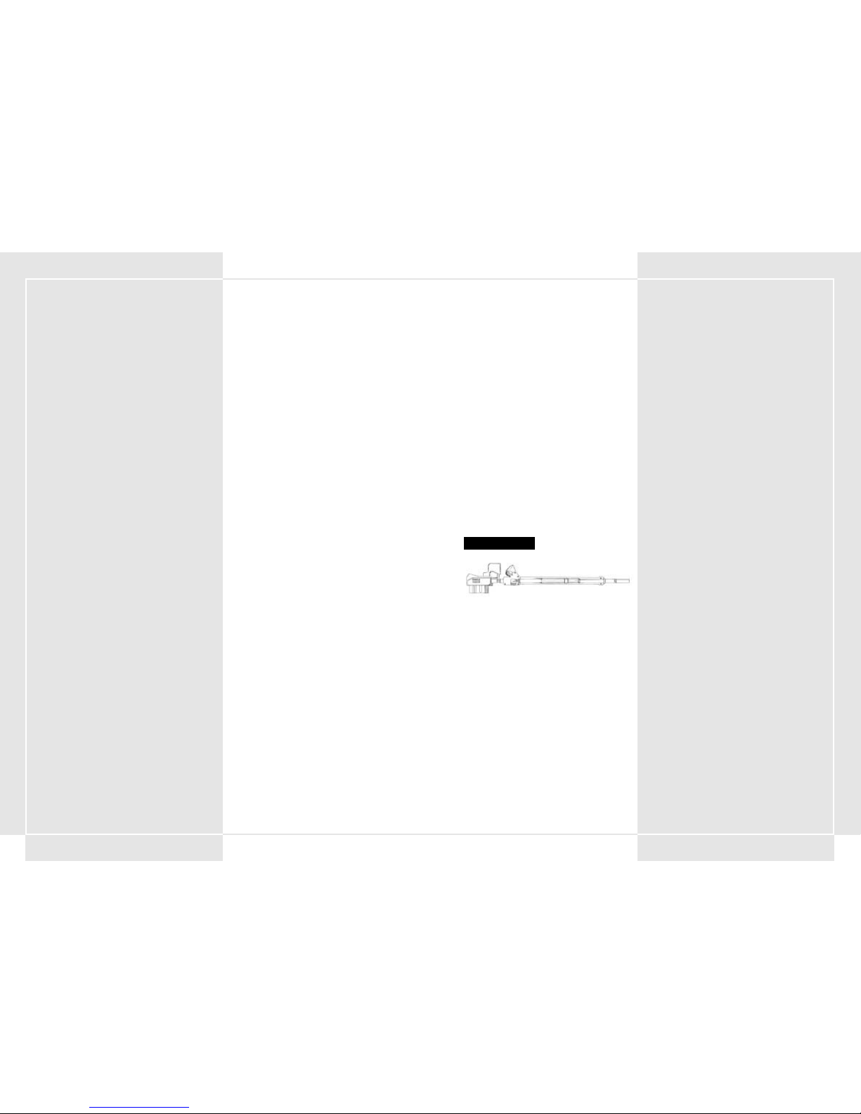
4342
2-10 ARMES CHARGÉES SUR LE VT
FUSIL de 270 mm
Cette arme tire des cartouches perforantes à basse trajectoire.
FUSIL D ASSAUT de 200 mm
Bien que de portée limitée, son système de rechargement
automatique lui procure la cadence de tir la plus élevée.
FUSIL D ASSAUT de 270 mm
Avec sa cadence de tir en salve de 5 coups, cette arme peut
devenir votre arme anti-VT principale en raison de sa très grande
capacité de destruction. Toutefois, par comparaison avec d'autres
modèles de la même génération, sa portée est relativement
courte.
FUSIL DOUBLE de 315 mm
Cette arme tire simultanément deux balles perforantes.
FUSIL À TIR RAPIDE de 315 mm
Avec sa cadence de tir en salve de trois coups, cette arme offre
une cadence de tir supérieure à celle d'un fusil normal.
FUSIL À TIR RAPIDE de 355 mm
Avec sa cadence de tir en salve de trois cartouches, cette arme
offre une cadence de tir supérieure à celle d'un fusil normal.
FUSIL DE PRÉCISION de 320 mm
Cette arme est conçue pour éliminer des cibles à grande distance.
Sa portée de tir est supérieure à celle d'un fusil normal.
FUSIL AK19-4A SANS RECUL
Ce fusil tire des balles explosives. Très léger, il offre une
puissance de feu équivalente à celle du fusil. Toutefois, en raison
de leur lenteur, il est relativement facile d'éviter ses projectiles.
FUSIL AK19-77 SANS RECUL
Ce fusil tire des balles explosives dotées de fusées de contact. Les
munitions exploseront et produiront des dommages même sans
impact direct.
FUSIL À PAROI INTERNE LISSE de 315 mm
Cette arme tire des cartouches APFSDS (perforantes stabilisées
par aileron et sabot amovible) à basse trajectoire. Il possède
également une portée de tir plus longue que le fusil.
2-3 TYPES DE VT
Les VT sont classés par type, en fonction de leur poids. Ils
peuvent être de type léger, moyen ou lourd.
1. VT légers
L'atout de ce modèle réside dans sa mobilité. Il a été
développé pour une utilisation dans des situations de
poursuite d'un ennemi en fuite ou d'attaque de positions
ennemies après destruction de leur puissance de feu
principale. Les VT légers sont transportables par voie
aérienne et peuvent être parachutés au-dessus de zones de
largage précises. Ils peuvent ainsi se révéler déterminants en
cas d'attaques aériennes de bases ennemies.
2. VT moyens
Les VT de classe moyenne constituent la puissance de feu
principale de la division spéciale de Panzers. Une de leurs
caractéristiques principales est d'offrir un compromis
équilibré entre puissance de feu et blindage d'un côté et
agilité et mobilité de l'autre. Des trois types de VT en
exploitation, celui-ci est le plus répandu. Ce VT offre
également les meilleures capacités d'évolutivité pour le
nombre d'options (armes et blindages) que vous pouvez
ajouter.
3. VT lourds
VT dotés de blindages lourds et d'une puissance de feu
considérable. En revanche, ils sont moins mobiles que les VT
légers ou moyens. Avec la puissance de leur arsenal offensif
et l'épaisseur de leur blindage, ces VT servent
essentiellement à protéger les positions et les bases clés.
2-4 DÉPLACEMENT
Les VT moyens peuvent se déplacer à une vitesse moyenne de 100
kilomètres/heure. Ils peuvent s'éloigner du danger de 205
kilomètres au maximum. Ces atouts principaux peuvent varier en
fonction de la maintenance des pièces, de la topographie et de
l'habileté du pilote.
Le balancier, qui contrôle la stabilité de l'unité des jambes,
influence le déplacement du VT. Cette capacité est exprimée en
points. Plus les points du balancier sont élevés, plus votre VT est
stable.
2-5 RÉSERVOIRS DE CARBURANT ET
RÉSERVOIRS DE RECHANGE
Un réservoir de carburant fixe est chargé sur le tronc du VT. La
contenance du réservoir varie en fonction de son type. Le VT M7 Decider (élément principal des Forces du Pacifique) utilise des
réservoirs de 6 000 gallons qui lui assurent chacun une
autonomie de fonctionnement de 5 minutes environ.
Certains VT peuvent se doter de réservoirs de rechange qui leur
confèrent une plus grande autonomie de fonctionnement.
Suivant son type, un VT peut s'équiper d'un nombre variable de
réservoirs de rechange, la moyenne se situant autour d'un ou
deux.
Un réservoir de rechange a une contenance de 6 000 gallons.
Pour gagner en vitesse et en mobilité, appuyez sur le bouton
Tank Detach (Détacher réservoir) de la console principale pour
abandonner vos réservoirs de carburant. Veillez aussi à détacher
rapidement les réservoirs de rechange dès qu'ils se vident.
2-6 CONSOMMATION DE CARBURANT ET TEMPS
DE DÉPLACEMENT ESTIMÉ
Vous pouvez vous ravitailler et récupérer tout le carburant utilisé
au combat en émettant une demande de ravitaillement. Si vous
venez à manquer de carburant et que vous n'avez pas la
possibilité de vous ravitailler, votre VT risque d'être immobilisé.
Pour éviter les situations de ce type, le briefing de préparation à
la bataille vous fournit une estimation du temps de déplacement
prévu. Pensez aux déplacements nécessaires pour chaque
bataille, puis déterminez le nombre de réservoirs de rechange
nécessaires.
La vitesse la plus économique du VT est la troisième. Elle offre le
meilleur rapport de mouvement et de vitesse en patrouille. Vous
pouvez allonger votre durée de déplacement en réduisant le
nombre de glissements latéraux et autres mouvements de ce type
qui consomment du carburant.
2-7 BLINDAGE DÉFENSIF
La puissance défensive du VT correspond à la « résistance de son
blindage ». Un compteur sur le tableau de bord indique quatre
niveaux de résistance. Chaque fois que le VT est atteint, il subit
des dommages et le compteur décroît. Le danger augmente pour
le pilote à mesure que la résistance du blindage diminue. Si le
compteur atteint un niveau de danger, un avertissement est
affiché. Vous devez alors quitter le champ de bataille ou
envisager de vous éjecter aussi vite que possible. (Pour plus
d'information sur l'éjection, consultez les sections 4-19 à 4-21.)
Vous pouvez ajouter un blindage supplémentaire à votre VT,
suivant son type.
2-8 ARME PRINCIPALE ET ARME SECONDAIRE
Les armes des VT sont divisées en deux catégories : principale et
secondaire. Ces armes n'ont rien à voir avec les armes
traditionnelles. Les armes principales sont montées sur les unités
d'armement du VT. Les armes secondaires sont montées sur
n'importe quelle autre partie du VT. Vous pouvez déterminer le
type d'une arme en fonction de sa position sur le VT. Les armes
ne sont pas catégorisées par puissance.
2-9 TOLÉRANCE DE POIDS D ARMEMENT
MAXIMALE
Les armes du VT doivent être considérées comme des options.
Certaines armes peuvent être utilisées sur n'importe quel type de
VT ; d'autres varient en fonction du VT sur lequel elles sont
montées. Vous pouvez choisir trois armes principales et trois
armes secondaires. Le poids des armes pouvant être chargé
diffère en fonction du type de VT. La tolérance de poids
d'armement maximale (le poids total des armes que peut
transporter le VT) est affichée pour vous aider dans votre choix.
FUSIL de 270 mm
Page 24

4544
RAFALE – MORTIER GUIDÉ ANTI-VT
Il s'agit de la seule arme anti-VT à tir vertical dotée d'un système
de guidage.
CANON À RAIL A
L'arme la plus récente développée par les PRF. L'arme tire des
munitions à des vitesses supersoniques, par impulsion
électromagnétique. Sa portée et sa puissance de feu sont sans
égales.
CANON À RAIL B
Canon à rail développé par le Hai Shi Dao. L'arme tire des
munitions à des vitesses supersoniques, par impulsion
électromagnétique. Sa portée et sa puissance de feu sont sans
égales.
LANCEUR DE MISSILES SUPERSONIQUES
AÉROPORTÉS
Cette arme tire des munitions perforantes propulsées par
réaction. Malgré sa portée et sa puissance de feu, les plus
puissantes de sa catégorie, le lanceur n'est pas doté d'un système
de guidage.
OBUSIER de 225 mm
Cette arme tire des obus-grenades, suivant une trajectoire
décrivant un arc. Bien que sa capacité de destruction soit limitée,
elle est capable d'infliger des dommages dans un rayon fixé. Elle
est très efficace dans les zones à haute densité de véhicules
blindés.
OBUSIER de 305 mm
Cette arme tire des obus-grenades, suivant une trajectoire
décrivant un arc. Bien que sa capacité de destruction soit limitée,
elle est capable d'infliger des dommages dans un rayon fixé. Elle
est très efficace dans les zones à haute densité de véhicules
blindés.
OBUSIER de 370 mm
Cette arme tire des obus-grenades, suivant une trajectoire
décrivant un arc. Elle est capable d'infliger des dommages dans
un rayon fixé. Suivant l'utilisation que vous en faites, l'obusier
peut être redoutablement efficace.
OBUSIER de 550 mm
Cette arme tire des obus-grenades, suivant une trajectoire
décrivant un arc. Dotée d'une grande capacité de destruction,
elle est capable d'infliger des dommages dans un rayon fixé.
MLRS 8 COUPS (système de lancement de roquettes
multiples)
Ce MLRS 8 coups tire des roquettes de grand calibre suivant des
angles de tir vertical. Son rayon de déflagration est capable
d'infliger des dommages importants. Très efficace pour dégager
une vaste zone de terrain.
FUSIL À PAROI INTERNE LISSE de 355 mm
Cette arme tire des cartouches APFSDS (perforantes stabilisées
par aileron et sabot amovible) à basse trajectoire. Par rapport au
fusil, il possède également une portée de tir plus importante.
FUSIL À PAROI INTERNE LISSE de 430 mm
Cette arme est la plus grande dans sa catégorie. Sa puissance de
destruction et sa portée de tir en font une arme très efficace.
MITRAILLEUSE ROTATIVE de 67 mm
Cette arme tire de petites cartouches perforantes à très grande
cadence. Étant donné sa puissance de feu relativement faible,
cette arme n'a pas une grande efficacité contre les VT. Toutefois
elle est très percutante contre les véhicules blindés et les
hélicoptères de combat.
MITRAILLEUSE ROTATIVE de 80 mm
Cette arme tire de petites cartouches perforantes à très grande
cadence. Étant donné sa portée relativement faible, cette arme
n'a pas une grande efficacité contre les VT. Toutefois elle est très
percutante contre les véhicules blindés et les hélicoptères de
combat.
MITRAILLEUSE ROTATIVE de 100 mm
Cette arme tire de petites cartouches perforantes à très grande
cadence. Étant donné sa portée relativement faible, cette arme
n'a pas une grande efficacité contre les VT. Toutefois elle est très
percutante contre les véhicules blindés et les hélicoptères de
combat.
MITRAILLEUSE LOURDE de 120 mm
Cette mitrailleuse est plus puissante que la mitrailleuse rotative.
Malgré sa cadence de tir très rapide, elle n'est pas efficace contre
les VT. Elle est toutefois très efficace contre les canons de soutien
mobiles.
MITRAILLEUSE LOURDE de 140 mm
Cette mitrailleuse est plus puissante que la mitrailleuse rotative.
Malgré sa cadence de tir très rapide, elle n'est pas efficace contre
les VT. Elle est toutefois très efficace contre les canons de soutien
mobiles.
MITRAILLEUSE LOURDE PITO de 135 mm
Mitrailleuse lourde qui se fixe sous le tronc du VT. Plus puissante
que la mitrailleuse rotative, sa fonction de tir rapide en fait une
arme secondaire intéressante.
LANCE-ROQUETTES ANTI-TERRESTRE MK21
Cette arme peut tirer six roquettes anti-terrestres moyennes
simultanément.
LANCE-ROQUETTES ANTI-TERRESTRE MK34
Cette arme peut tirer quatre roquettes anti-terrestres moyennes
simultanément, une charge mortelle pour n'importe quel VT.
CANON À RAIL
OBUSIER de 370 mm
MITRAILLEUSE de 67 mm
CANON MITRAILLEUSE de 120 mm
LANCE-ROQUETTES ANTI-TERRESTRE MK21
Page 25

4746
LANCE-FLAMMES
Arme de combat rapproché qui se fixe sous le tronc du VT. Sous
l'impact d'un tir direct de cette arme, un VT explose dans un
tourbillon de flammes.
ASSOMMOIR
Spécifiquement conçu pour le combat rapproché contre les VT,
un tir direct de cette arme provoque des décharges électriques
massives capables d'immobiliser temporairement le VT.
BRAS COUPANT
Ce grand bras coupant a été modifié pour être utilisé par un VT
en combat rapproché. Il s'agit de l'arme de combat rapproché la
plus destructrice.
GRENADE À RETARDEMENT
Cette grenade est spécifiquement conçue pour le combat
rapproché. Grâce aux fusées de contact à l'intérieur, la grenade
explose et inflige des dommages même sans contact direct avec
la cible.
GRENADE À RETARDEMENT À 3 COUPS
Cette grenade est spécifiquement conçue pour le combat
rapproché. Grâce aux fusées de contact à l'intérieur, la grenade
explose et inflige des dommages même sans contact direct avec
la cible.
FUMIGÈNE
Cette arme tire quatre cartouches de grenades fumigènes. Son
seul objectif est de créer une fumée épaisse qui aveugle l'ennemi
et met à mal ses capacités d'attaque.
MINE PROJECTILE ANTI-VT
Cette arme est capable de tirer simultanément trois mines
projectiles anti-VT.
RÉSERVOIR DE PROPERGOL
Réservoir de carburant pour le VT. Une fois le réservoir vide, il
peut être détaché pour alléger votre poids.
BLINDAGE SUPPLÉMENTAIRE
Un blindage supplémentaire permet d'améliorer la durée du vie
du VT. Il donne également au pilote la possibilité d'utiliser les
missiles guidés, chargés à l'intérieur du blindage. Pour les
projeter, appuyez sur F1 en cours de combat.
RAVITAILLEMENT
Le ravitaillement concerne les munitions et le carburant. Pour
obtenir un ravitaillement, vous devez demander un hélicoptère
de ravitaillement.
BOOM BOX
Cet antique lecteur de cassettes a été retrouvé dans la zone de
stockage du centre d'entraînement. Accrochez-le à l'intérieur du
cockpit pour combattre en musique.
MLRS 12 COUPS
Ce MLRS 12 coups tire des roquettes de grand calibre suivant des
angles de tir vertical. Son rayon de déflagration est capable
d'infliger des dommages importants. Très efficace pour conquérir
une vaste zone de terrain.
LANCE-MISSILES DOUBLE COMPACT
Unité compacte capable de lancer deux missiles qui se fixe sous
le tronc du VT.
LANCE-MISSILES TRIPLE COMPACT
Unité compacte capable de lancer trois missiles qui se fixe sous
le tronc du VT.
MISSILE GUIDÉ ANTI-VT ASLAM (missile d attaque
terrestre à distance)
Missile à guidage infrarouge. Suivant la programmation des
modes de déplacement du VT, sa précision d'acquisition de cible
s'améliore, et se traduit par un grand nombre de tirs directs.
POZIT – MISSILE GUIDÉ ANTI-VT
Missile à guidage infrarouge. Moins puissant que son homologue
ASLAM, il n'est reste pas moins un missile précis et destructeur.
MISSILE GUIDÉ COMPACT À CHARGE DOUBLE
Unité compacte capable de lancer deux missiles guidés qui se fixe
sous le tronc du VT. Bien que ses performances ne soient pas
élevées, il est équipé d'un système de guidage.
MISSILE GUIDÉ AVTDV
Missile anti-VT de grand calibre, également surnommé « tueur de
VT ». Son système de guidage avancé, sa portée de tir et sa
capacité de destruction en font le missile le plus dangereux.
CHALUMEAU À PLASMA ALC205
Conçu spécifiquement pour le combat rapproché avec les VT,
cette arme est très destructrice et a la possibilité d'abattre un
ennemi d'un seul tir direct.
CHALUMEAU À PLASMA ALC22B
Conçu spécifiquement pour le combat rapproché avec les VT,
cette arme est très destructrice et a la possibilité d'abattre un
ennemi d'un seul tir direct.
NAPALM
Vous pouvez charger des cartouches de napalm dans n'importe
quel lanceur compact qui se fixe sous le tronc du VT. Le napalm
est très efficace pour balayer un secteur ennemi en raison de sa
capacité naturelle à enflammer de vastes zones. Sous l'impact
d'un tir direct, un VT prend feu.
CHALUMEAU À PLASMA ALC205
MISSILE GUIDÉ ANTI-VT
GRENADE À RETARDEMENT
Page 26

4948
2-11 VISÉE DES ARMES À TRAJECTOIRE
INCURVÉE SUR LA CARTE DE GUERRE
Vous devez verrouiller votre cible avant d'utiliser une arme à
trajectoire de tir incurvée. Lorsque vous choisissez une arme à
trajectoire de tir incurvée, la cible, la direction du tir et le point
d'impact de l'arme sont illustrés par une ligne blanche sur la
carte de guerre. Vous pouvez utiliser ces informations pour
essayer de frapper l'ennemi même sans avoir verrouillé la cible.
2-12 FUSÉE À RETARDEMENT
Les munitions du canon Ak19-77 sans recul et les grenades à
courte portée contiennent une fusée à retardement (plutôt
qu'une fusée de contact, comme dans les engins d'artillerie
normaux). Les fusées à retardement trouvent leur cible par
magnétisme et explosent ensuite à une distance fixée. Grâce à ce
système, vous n'êtes pas tenu d'atteindre votre cible directement
pour l'endommager. Dans une bataille de VT mobiles et rapides,
ces fusées à retardement peuvent jouer un rôle de soutien très
efficace pour frapper l'ennemi.
2-13 LEURRES
Pour se défendre contre les missiles guidés par radar, le VT est
équipé d'une unité de projection de paillettes. Les paillettes
explosent et se dispersent dans quatre directions dès qu'un
missile est tiré contre le VT. Des éclats d'aluminium se dispersent
dans l'air pour leurrer le système de guidage du missile, et lui
faire manquer sa cible.
Si vous effectuez un glissement sur le côté en plus de disperser
les paillettes, vous augmentez vos chances d'esquiver le missile.
TRAJECTOIRE INCURVÉE ET TRAJECTOIRE RECTILIGNE
Trajectoire incurvée
Trajectoire rectiligne
3-1 APPORTS DU COOS DE 2 ÈME GÉNÉRATION
Le COOS qui contrôle tous les mouvements du VT en est
actuellement à sa deuxième génération et dispose de
fonctionnalités opérationnelles accrues. Outre une augmentation
de la puissance du processeur, le COOS dispose d'un nouveau
système de guidage d'armes anti-VT, et d'un système de tir à
estimation de cible (FSS). Ces apports donnent au VT une plus
grande puissance destructrice encore. Ci-dessous, une liste de
nombreuses fonctions du COOS de deuxième génération.
3-2 FSS (système de tir à estimation de cible)
Le FSS analyse le schéma de déplacement du VT cible, ainsi que
la distance et la durée de déplacement en l'air du projectile. Il
place ensuite automatiquement le localisateur de cible sur la
prochaine position probable de l'ennemi. Pour sélectionner
alternativement le mode de visée du FSS et le mode de visée
normal, appuyez sur le bouton FSS. Pour plus d'informations sur
le FSS, consultez la section 5-4.
3-3 VITESSE SURMULTIPLIÉE
Cette fonction permet d'augmenter considérablement la vitesse du
VT pendant une courte durée. Elle désactive le « limiteur de vitesse
» qui protège plusieurs joints d'une usure excessive. Pour plus
d'informations sur la fonction de vitesse surmultipliée, consultez
la section 4-6.
3-4 FURTIVITÉ
Le VT dispose d'une fonction de furtivité qui lui permet
d'échapper aux radars. La furtivité résulte de l'utilisation de
peinture à absorption d'ondes radar, de l'amélioration du
système d'échappement des gaz et de l'aérodynamisme de la
carlingue.
3-5 ARMES GUIDÉES
Une des caractéristiques principales du COOS de deuxième
génération est l'augmentation du nombre d'armes guidées. De
nouveaux missiles guidés anti-VT complètent le système de
guidage actif par laser déjà en place. Ce système analyse les
schémas de déplacement de l'ennemi et anticipe sa prochaine
position en utilisant le FSS en temps pour plus de précision de tir.
On place beaucoup d'espoir dans l'efficacité de ce nouveau
système dans les batailles anti-VT.
SECTION 3. FONCTIONS
SPÉCIALES DU COOS DE 2 ÈME
GÉNÉRATION
4-1 SÉQUENCE DE DÉMARRAGE
Lorsque vous entrez dans un VT pour la première fois, avant de
partir au combat, la batterie, le réservoir de carburant et ses
armes sont au maximum de leur capacité. La séquence de
démarrage du VT est la suivante.
1. Refermer le capot du cockpit
Appuyez sur le bouton Cockpit Hatch (Capot Cockpit) à
droite. Vérifiez si le capot du cockpit est ouvert ou fermé.
2. Appuyer sur le bouton Ignition (Allumage)
Appuyez sur le bouton Ignition sous le bouton Cockpit
Hatch. Le moteur démarre et le générateur met le cockpit
sous tension. Le système d'exploitation du VT se met en ligne
et les procédures de contrôle des fonctions défilent avant
l'affichage de l'écran Startup Function (fonction de
démarrage).
3. Fonctions de démarrage
Une fois le contrôle des fonctions affiché, vous devez activer
chacune des fonctions suivantes tout en vous assurant de
leur opérabilité. Actionnez-les une à une avec votre index
pour les activer.
•Oxygen Supply System (OSS) – Approvisionne le cockpit
en oxygène.
• Filter Control System (FCS) – Interrupteur qui actionne le
système d'évacuation des gaz chauds. Élimine les gaz
chauds et stabilise le moteur.
• VT-Location Measurement (VT-LM) – Système
d'estimation du localisateur d'unité. Fonction permettant
d'afficher automatiquement votre VT sur la carte de
guerre.
• Buffer Material (BM) – Système qui génère un matériau
protecteur autour du cockpit pour le protéger contre les
attaques. Il enveloppe le cockpit et la zone du tronc du VT
d'un gel dur protecteur.
• Fuel Flow Rate (FFR) – Système de régulation des flux de
carburant. Il contrôle les flux de carburant et dispense la
quantité de carburant appropriée, suivant la condition
courante du moteur.
4. Appuyer sur le bouton Start
Une fois que vous avez terminé la séquence de démarrage
initiale, une image de votre environnement extérieur
s'affiche à l'écran. L'énergie est transmise aux différentes
articulations du VT par un vérin. Lorsque les différents
systèmes ont traversé la ligne de stabilisation, appuyez sur
le bouton Start. Après avoir contrôlé les différentes
fonctions, votre VT se positionne en mode de démarrage,
vous permettant de commencer à le contrôler.
4-2 CALAGE DU MOTEUR AU DÉMARRAGE DU VT
Si vous appuyez sur le bouton Start alors que tous les systèmes
n'ont PAS traversé la ligne de stabilisation, certaines articulations
se débloqueront, annulant la séquence de démarrage et calant le
VT. Ce système empêche d'utiliser le VT au-delà de ses limites. Si
vous calez le VT au cours du démarrage, détendez-vous et
attendez que les différents compteurs système se réactivent. Vous
pouvez ensuite essayer à nouveau de démarrer la machine en
appuyant sur le bouton Start.
SECTION 4. COMMANDES DU VT
Ligne de
stabilisation
CONTRÔLE D ÉTAT DES SYSTÈMES PRINCIPAUX
ÉCRAN DE DÉMARRAGE
Page 27
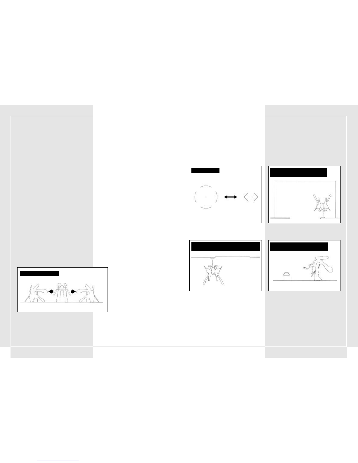
5150
COMMANDES DE BASE
4-3 SE DÉPLACER ET S ´ARRÊTER
Se déplacer et s'arrêter sont les deux mouvements de base du VT.
Vous pouvez passer de la 1 ère à la 5 ème vitesse à l'aide du levier
de vitesses. Appuyer sur l'accélérateur augmente le nombre de
tours/minute (RPM) du moteur et fait avancer le VT. Vous pouvez
mettre le levier en marche arrière (R) pour reculer. Pour arrêter
le VT, retirez votre pied de l'accélérateur et appuyez sur la pédale
de frein. Si vous faites des virages serrés alors que vous vous
déplacez à grande vitesse, vous risquez de faire basculer le VT.
Alors faites attention.
4-4 ACCÉLÉRATION ET DÉCÉLÉRATION
La puissance d'accélération et de décélération varie en fonction de
la pression que vous exercez sur l'accélérateur. Pour ralentir, vous
devez appuyer sur la pédale de frein ou rétrograder les vitesses.
Au point mort (N), votre vitesse est de 0 km/h. Chaque vitesse vous
permet de gagner de la vitesse mais vous fait perdre du couple.
Dans les zones où la vitesse n'augmente pas régulièrement en
souplesse, vous avez intérêt à rétrograder pour économiser votre
carburant. Placer le levier de vitesses sur R fait reculer le VT.
4-5 ROTATION
Pour que le VT effectue une rotation, appuyez sur la poignée de
rotation gauche vers
ou . La vitesse de rotation augmente en
fonction de la pression exercée sur la poignée de rotation dans l'une ou
l'autre direction. Si le balancier ne parvient pas à maintenir l'équilibre
du VT, celui-ci se renversera. Soyez prudent.
4-6 SURMULTIPLIÉE
Cette fonction a été développée à la demande de plusieurs pilotes
émérites. Elle désactive le limiteur de vitesse qui protège différents
joints de l'usure due à la vitesse. Lorsque vous appuyez sur le
bouton Overdrive (Surmultipliée), vous déverrouillez le limiteur.
Pour le reverrouiller, appuyez à nouveau sur le bouton Overdrive.
Lorsque le VT est en surmultipliée, la consommation de carburant
triple par rapport au fonctionnement normal. N'en abusez pas !
4-7 GLISSEMENT LATÉRAL
Un des moyens dont dispose le VT pour esquiver les tirs dont il est
la cible. C'est l'une des différences principales entre le VT et un
char standard. Vous pouvez vous projeter rapidement vers la droite
ou la gauche grâce au programme du système d'exploitation. Vous
pouvez également utiliser cette fonction pour reprendre
rapidement l'équilibre lorsque vous risquez de vous renverser. Le
glissement latéral consiste en un mouvement rapide dans l'une des
quatre directions pré-programmées. Il s'obtient par combinaison
d'accélération et d'utilisation du balancier. Le balancier renforce
automatiquement les joints/articulations qui subiront l'essentiel de
l'usure. Pour effectuer un glissement latéral, orientez le levier de
rotation vers
ou ^ tout en appuyant sur la pédale de
glissement latéral. Le glissement latéral est un moyen très efficace
pour esquiver une attaque ennemie. Vous pouvez effectuer un
autre mouvement en laissant le levier de vitesses au point mort (N)
et en appuyant sur la pédale de glissement latéral. Votre VT se
fend ainsi en avant. Si vous procédez de la même manière avec le
levier en marche arrière (R), vous effectuez une fente en arrière.
4-8 LIMITES FONCTIONNELLES DU GLISSEMENT
LATÉRAL
Les glissements latéraux exercent une grande pression sur les
articulations du VT. Pour limiter cette usure, le vérin utilise une
grande quantité d'énergie. L'énergie produite par le générateur est
recyclée dans la batterie principale, mais la puissance de la
batterie est grandement réduite à chaque glissement latéral. Dans
les cas où l'énergie disponible n'est pas suffisante, le glissement
latéral est automatiquement annulé. Lorsque la batterie manque
d'énergie, un voyant de surchauffe s'allume. N'effectuez pas de
glissement latéral dans ces conditions.
4-9 RÉGULATEUR D ´INCLINAISON EN GLISSEMENT
LATÉRAL
Dès que le mouvement du VT dépasse les limites du balancier, le VT
risque de se renverser. Les renversements se produisent au cours
de manœuvres inconsidérées ou de virage à grande vitesse. Il peut
également se produire en cas de d'impact de tir ennemi. Dès que
le VT menace de se renverser, appuyez sur la pédale de glissement
latéral pour le rééquilibrer. Toutefois, si la batterie du VT manque
de puissance, vous ne serez pas en mesure d'effectuer la
manœuvre. Si vous vous renversez, relâchez l'accélérateur, puis
appuyez à nouveau dessus pour redresser le VT.
4-10 COUPE-CIRCUIT
Dans les situations où les dommages que vous subissez dépassent
la limite tolérée, votre VT se met automatiquement hors tension
(coupe-circuit) pour éviter aux différentes articulations des
dommages supplémentaires. Lorsqu'une coupure se produit, tous
les verrous se débloquent et le VT cale. Vous devez alors refaire
rapidement la séquence de démarrage pour remettre le VT sous
tension.
GLISSEMENT LATÉRAL
4-11 COMMANDES DU MANIPULATEUR
Le VT est doté d'un bras actionné par un manipulateur. Ce bras
est capable d'ouvrir et de fermer des portes, et de déplacer des
marchandises. Le manipulateur est fixé sur le côté gauche de la
carlingue principale. Pour le mettre en marche, appuyez sur le
bouton du manipulateur. En centrant le manipulateur sur une
cible et en appuyant sur le bouton d'arme secondaire, vous
pouvez saisir l'objet. Étant donné que vous devez appuyer sur le
bouton d'arme secondaire pour utiliser le manipulateur, vous
ne pouvez pas utiliser d'arme secondaire à ce moment précis.
UTILISATION DU MANIPULATEUR POUR
CONTRÔLER UN ASCENSEUR
UTILISATION DU MANIPULATEUR POUR OUVRIR
ET FERMER LES PORTES DES SOUTES
MANIPULATEUR
RÉCUPÉRATION D OBJETS À L AIDE DU
MANIPULATEUR
Visée avec une arme secondaire en mode normal
Visée en mode manipulateur
Page 28

5352
MONITEUR DU VT
4-12 CHANGEMENT DE LA CAMÉRA PRINCIPALE
La perspective du VT est déterminée par la caméra principale.
L'image est affichée à l'intérieur du cockpit. La caméra offre
normalement une vue de ce qui se trouve devant elle. En
appuyant sur la molette du stick gauche
,
, ou vous
pouvez élargir la zone visualisée. En appuyant sur la molette du
stick de commande, vous pouvez recentrer la vue au centre
direct du VT. En utilisant cela et le moniteur secondaire (décrit
plus loin) vous pouvez déplacer votre VT et améliorer son
efficacité sur le champ de bataille.
4-13 POUSSIÈRE ET BOUE SUR LA CAMÉRA
PRINCIPALE
En combat, vous devez être en mesure de voir clairement ce qui
vous entoure. Si l'écran se couvre de poussière ou de boue,
appuyez sur le bouton de nettoyage.
PERSPECTIVES DE LA CAMÉRA
4-14 FONCTIONS DU MONITEUR SECONDAIRE
Le bouton de sélection du mode moniteur secondaire sous le
moniteur principal vous donne le choix entre quatre modes.
• Mode Vue frontale
Vous montre ce qui se trouve directement devant le VT.
Utilisez cette vue avec la fonction de changement de site
pour observer plus efficacement votre environnement.
• Mode Vue arrière
Vous montre ce qui se trouve directement derrière le VT.
Comme précédemment, utilisez cette vue avec la fonction de
changement de site pour observer plus efficacement votre
environnement.
• Mode Verrouillage de vue
Vous permet d'obtenir un zoom avant de la cible verrouillée.
Une cible se trouvant à très grande distance sera affichée
dans le moniteur secondaire sans même que vous ayez à
effectuer un zoom avant.
• Mode Vue du ciel
Vous offre une vue plongeante, prise à 50 mètres au-dessus
du VT. Cette vue est utile pour découvrir ce que dissimulent
les objets et les angles morts.
4-15 ÉQUIPEMENT DE VISION DE NUIT
Le VT est équipé d'une caméra de vision nocturne qui sert dans
les situations de faible luminosité (nuit ou brouillard). Pour
utiliser la caméra, appuyez sur le bouton de caméra nocturne du
tableau de bord. Le VT utilise le JGVS-V442 de type passif qui
projette une lumière infrarouge sur un sujet puis l'affiche au
format d'image à l'écran. La caméra de vision nocturne sert non
seulement dans les zones sombres et enfumées, mais également
pour détecter les cibles camouflées. La caméra voit jusqu'à 2,5
kilomètres de distance et affiche les images sur votre moniteur
principal. Lorsque vous utilisez la caméra de vision nocturne dans
l'obscurité, les éclairs du combat ou des grenades aveuglent
temporairement la caméra.
JCS (système de commande complet)
4-16 RÉSUMÉ DU JCS
Le JCS est un système qui utilise les données stratégiques
militaires et les informations les plus récentes pour optimiser
l'efficacité du VT. Son objectif principal est de fournir les
informations les plus récentes à propos du champ de bataille, des
forces alliées, ennemies et des autres compagnies/bataillons. Le
système est conçu pour améliorer l'efficacité globale du VT au
combat. Les pilotes de VT comme les commandants de section
doivent savoir l'utiliser efficacement.
Le JCS utilise un réseau qui passe par la salle de contrôle de
transport de VT et les salles de contrôle des différentes
compagnies/bataillons, de sorte qu'il transporte les nouvelles les
plus récentes dans les deux sens, aux personnes qui en ont
besoin. Ce système envoie des messages par les moniteurs vidéo
des VT, les satellites de reconnaissance et autres divisions de
commandement, puis édite les données en temps réel dans les
salles de contrôle des bataillons. Il analyse ensuite les données
et les envoie aux différentes sections. Les données sont envoyées
au VT via un réseau de communication et s'affichent sur les
différents moniteurs du cockpit. Grâce à ce système, les pilotes
peuvent consulter la carte, les positions ennemies et assurer des
tirs de soutien pour les forces.
DIAGRAMME DU RÉSEAU DU SYSTÈME DE
COMMANDEMENT COMPLET
Centre de commandement de transport
de VT
VT
Avion de reconnaissance
Satellite de reconnaissance
Page 29

5554
4-17 AFFICHAGE MULTI-MONITEUR
L'affichage multi-moniteur dans la partie supérieure du moniteur
principal sert à afficher les informations envoyées au centre de
commandement principal. Le multi-moniteur n'est pas toujours
affiché. Vous pouvez activer ou désactiver l'affichage multimoniteur en appuyant sur le bouton d'ouverture/fermeture du
moniteur multiple.
4-18 INFORMATIONS AFFICHÉES SUR LE MULTIMONITEUR
Les informations suivantes sont affichées sur le multi-moniteur.
1. Carte de guerre
Permet de découvrir une zone de 25 km de rayon, autour de
votre position. Utilisez le bouton de zoom avant/arrière
pour agrandir la zone à un rayon maximum de 5 000 km.
2. Informations spécifiques à votre VT
Indique les statistiques et l'état actuels de votre VT. Utilisez
ces informations pour contrôler la quantité de blindage ou
de carburant dont vous disposez.
3. Objectif de la mission
Affiche des informations sur l'objectif principal de la mission
en cours. En cas de changement des paramètres de la
mission, ces informations sont affichées ici. Les pilotes et
particulièrement les commandants de section doivent
consulter ces informations.
4. Section
Contient uniquement les données du commandant de
section. Vous pouvez consulter ces informations pour
connaître les ordres des autres membres de cette section.
5. Informations sur l'ennemi
Contient des informations sur les VT ennemis : leur portée
de tir, puissance offensive, etc. Contient également des
données sur différentes machines de soutien.
Votre VT
VT
Autres objets terrestres (chars, canons)
Forces aériennes (hélicoptère, bombardiers)
Zone d'impact estimée pour une arme à trajectoire incurvée
Balles
Zone d'impact estimée pour votre arme principale
Zone d'impact estimée pour votre arme secondaire
MONITEUR CARTE
AFFICHAGE MULTI-MONITEUR
VÉRIFICATION DU NOMBRE D'ENNEMIS DÉTRUITS
Nombre et type d'ennemis détruits
Nombre total d'ennemis détruits
Objectif principal
Ordre relatif à l'objectif principal
ÉCRAN D'OBJECTIF PRINCIPAL
Ordre réalisé par l'ailier 1
Ordre réalisé par l'ailier 2
ÉTAT DE L'AILIER
Réservoir 1
Réservoir 2
Blindage supplémentaire
Nombre de points restants sur le
blindage supplémentaire
ÉTAT DE VOTRE VT PERSONNEL
PROCÉDURES D ´URGENCE
4-19 PRÉPARATION À L ÉVACUATION
Le VT dispose d'une fonctionnalité d'évacuation pour la sécurité
du pilote. Si vous subissez des dommages continus, si la
résistance de votre blindage s'épuise (voir section 2-5) ou si votre
VT atteint des limites dangereuses pour votre sécurité, protégezvous en vous éjectant aussitôt que possible. L'enveloppe de gel
protecteur qui recouvre le cockpit deviendra votre nacelle de
survie, qui sera éjectée à l'aide d'un petit réacteur placé à sa
base.
4-20 BOUTON D ´ÉJECTION D URGENCE
Le bouton d'éjection d'urgence est placé à droite de la console.
Il est protégé par un couvercle transparent noir et jaune.
Étant donné qu'il se trouve du même côté que le bouton de
démarrage, faites attention à ne pas appuyer par erreur sur le
bouton de démarrage. Lorsque vous appuyez sur le bouton,
votre cockpit est expulsé par l'arrière du VT. Dès l'éjection,
l'enveloppe de gel se transforme en un airbag recouvrant
entièrement le cockpit pour vous protéger du choc à
l'atterrissage.
4-21 PROCÉDURES D ´ÉJECTION D ´URGENCE EN
RIVIÈRE OU EN MER
Étant donné que le VT n'est pas étanche et amphibie à 100%, il ne
peut naviguer dans des masses d'eau de plus de 20 mètres de
profondeur et ne peut pas se mouvoir dans ces circonstances. Si
vous coulez à plus de 20 mètres de profondeur, l'eau s'infiltrera
dans le cockpit recouvert de gel, vous obligeant ainsi à vous
éjecter. La procédure d'éjection sous l'eau n'est pas différente de
celle utilisée sur la terre ferme. L'enveloppe de gel formera un
airbag qui vous remontera à la surface.
4-22 FEU DANS LA CARLINGUE
Dès qu'un incendie se déclare dans la carlingue, vous devez agir
vite. Les dommages provoqués par les lance-flammes ou par des
tirs trop nourris peuvent endommager le blindage et amenuiser
la résistance de votre VT. Si l'alarme d'incendie se déclenche et
que les voyants d'alerte du cockpit clignotent, recherchez dans
quelle partie se trouve le feu et appuyez sur le bouton
d'extincteur du tableau de bord.
BOUTON D ÉJECTION D URGENCE
PROCÉDURE D ÉJECTION DU PILOTE
BLINDAGE DE RÉSISTANCE ATTEIGNANT SA LIMITE
Page 30
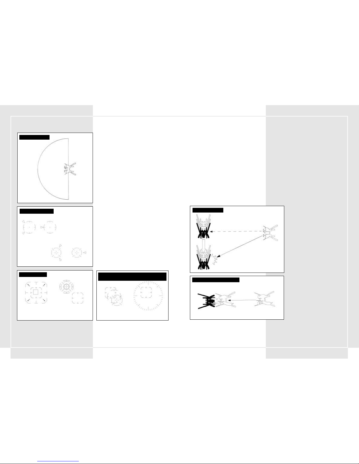
5756
5-1 VISÉE ET TIR
Pour viser, placez le réticule de visée sur l'ennemi à l'écran à
l'aide du stick de visée droit. Les armes du tronc sont libres de
leurs mouvements et offrent un rayon de visée maximum de 180°
au VT. Une fois que vous avez placé le curseur au-dessus de
l'ennemi, vous pouvez tirer avec votre arme principale ou
secondaire en appuyant sur la gâchette de votre arme
principale ou secondaire.
5-2 FONCTION DE VERROUILLAGE
Dans le VT, une fonctionnalité de verrouillage spéciale vise
automatiquement certains ennemis. Une fois que le réticule de
visée commence à clignoter à l'écran, il vous suffit d'appuyer sur
le bouton de verrouillage du stick de visée droit pour
verrouiller votre cible. Une fois le verrouillage activé, si vous
appuyez sur la gâchette de votre arme principale ou
secondaire, l'ennemi est automatiquement visé. Vous pouvez
désactiver le verrouillage en appuyant à nouveau sur le bouton
de verrouillage une fois la cible ennemie détruite, ou disparue
de l'écran.
Remarque : Étant donné que la fonction de verrouillage a été
essentiellement conçue contre les VT, vous ne pouvez pas
verrouiller d'autres cibles que des VT ou des canons.
5-3 VISÉE EN COMBAT RAPPROCHÉ
Parmi les armes secondaires du VT, on compte plusieurs armes
de combat rapproché. Le chalumeau à plasma ALC205 en est un
bon exemple car cette arme insolite ne peut servir que sur un VT.
Vous devez toutefois faire attention. Si vous utilisez une de ces
armes, votre cible sera légèrement différente des cibles
normales et vous passerez en mode de combat rapproché. Ce
mode de visée est utile pour le combat rapproché contre un
ennemi rapide immédiatement en face de vous. Le réticule ne
fonctionne que sur les objets placés directement en face de
votre VT. Si vous appuyez sur le bouton d'arme secondaire alors
que l'ennemi est en face de vous, vous chargez et frappez
l'ennemi avec votre chalumeau à plasma.
SECTION 5. ATTAQUE DU VT
DISTANCE DE VISÉE
RAYON DE VISÉE
180
°
VISÉE D'ARME SECONDAIRE
Hors de portée de tir À portée de tir
VISÉE D'ARME PRINCIPALE
Hors de portée de tir À portée de tir
VERROUILLAGE
Verrouillage possible Post-verrouillage
CURSEURS EN MODES DE COMBAT NORMAL ET
RAPPROCHÉ
Mode normal Mode rapproché
5-4 FSS (système de tir à estimation de cible)
Le FSS est un système de tir conçu pour analyser les données de
combat et les schémas de déplacement des VT ennemis.
Le bouton FSS du stick de visée vous permet passer du mode de
tir normal au mode de tir à estimation de cible, qui vous permet
d'anticiper la prochaine position probable de l'ennemi. Pour
revenir au mode de tir normal, appuyez à nouveau sur le bouton
FSS.
Remarque : Le FSS est une fonction de la deuxième génération du
système d'exploitation. On ne la trouve donc pas sur les VT dotés
du système de première génération. Les données d'estimation sur
le schéma de déplacement de l'ennemi ne sont pas parfaites, et
si l'adversaire connaît bien le système, il peut procéder à des
déplacements que le FSS sera incapable d'anticiper. Le FSS sera
donc inefficace face à certains adversaires.
5-5 PORTÉES DE TIR DES DIFFÉRENTES
ARMES
Chaque arme possède une portée de tir qui lui est propre. Le
pilote doit assimiler les portées de tir maximale et effective de
chacune des armes de son arsenal. La portée de tir effective de
chaque arme est affichée à gauche ou à droite de la cible du
moniteur principal et est définie par le système de contrôle
d'artillerie.
La portée de tir de l'arme principale est affichée à droite du
réticule. La portée de tir de l'arme secondaire est affichée à
gauche. Les portées de tir des deux armes se superposent audessus du réticule. Si l'ennemi se met hors de portée, un message
vous en avertit.
5-6 NOTES SUR LE TIR À PORTÉE DE TIR
EFFECTIVE
La portée de tir effective a été conçue essentiellement pour
s'afficher sur le moniteur principal. Toutefois, elle sert
essentiellement en combat anti-VT. Lorsque vous affrontez un
adversaire moins blindé que le VT (un char par exemple), il est
probable que vos tirs soient suffisamment puissants pour
éliminer quelques ennemis, même hors de portée. Par ailleurs, la
portée de tir effective est programmée en fonction de l'épaisseur
du blindage du VT, d'après les normes de la Pacific Rim
Organization. Par conséquent, si une cible protégée par un
blindage lourd se trouve à portée de tir effectif, il est possible
qu'elle ne soit pas endommagée par le tir. Faites attention.
AVEC LE CHALUMEAU À PLASMA
Mouvement très rapide
LIGNES DE TIR FSS
Position de la cible verrouillée au moment du tir
Position de la cible verrouillée au moment de l'impact du projectile
Page 31

5958
5-7 UTILISATION DE LA PORTÉE DE TIR
EFFECTIVE
Un facteur très important dans une bataille de VT concerne votre
équipement qui doit être plus performant que celui de l'ennemi et
vous donner l'avantage dans un combat. Si votre portée de tir
effective est supérieure à celle de votre adversaire, vous pouvez
porter vos attaques tout en demeurant hors de sa portée. Si vous
avez plus de portée que l'ennemi, vous pouvez vous contenter de
vous approcher suffisamment pour tirer. Si vous avez la possibilité
de détruire l'ennemi sans encaisser de dommages, tirez le meilleur
parti de cet avantage. Ne soumettez pas votre VT ou vous-même à
un danger inutile.
5-8 ATTAQUE DE SUPPRESSION TERRESTRE
Les armes telles que les grenades, le MLRS et le napalm explosent
près de la surface du sol et atteignent les ennemis qui se trouvent
dans une zone donnée. Faire usage de ce « tir de suppression » peut
s'avérer être une tactique très efficace pour éliminer des ennemis
regroupés.
5-9 CHANGEMENT D ´ARME
Un des secteurs dans lesquels les VT surclassent toutes les autres
unités est leur capacité à s'équiper d'armes très variées. Un VT peut
transporter 3 armes principales et 3 armes secondaires. Toutefois, il
ne peut en utiliser qu'une seule à la fois. Choisissez vos armes
principales et secondaires à l'aide du bouton de contrôle des
armes.
5-10 ARMES À CHARGEUR
Certaines de vos armes utilisent des chargeurs. Pour insérer un
nouveau chargeur dans l'arme, appuyez sur le bouton de
rechargement. Les balles restantes et le nombre de chargeurs
supplémentaires sont répertoriés dans le tableau de bord.
SYSTÈME DE CHANGEMENT D ARMETIR DE SUPPRESSION AU SOL
Portée effective = 400 mm
Portée effective = 1000 mm
Hors de portée = 1600 mm
PORTÉE DE TIR EFFECTIVE
(fusil de 270 mm) (0 à 1 500 mm)
PORTÉE DE TIR EFFECTIVE
(lance-roquettes MK34) (500 à 1000 mm)
Portée effective = 600 mm
Hors de portée = 1600 mm
Hors de portée = 300 mm
6-1 EN GÉNÉRAL
Cette section explique les principes de base du déplacement du
VT sur le champ de bataille.
Le mouvement permet de se soustraire au champ de vision de
l'ennemi et d'éviter les endroits où pourraient se dissimuler des
ennemis. Il sert également à éviter les zones à haute densité de
tir ennemi. Un pilote se doute que l'ennemi concentrera ses VT
sur un terrain favorable aux VT. Il faut donc noter que les régions
où les VT ont des difficultés à se déplacer peuvent offrir des
avantages tactiques.
Lorsque vous vous déplacez dans des zones où votre VT pourrait
bien se retrouver coincé, vous pouvez avoir besoin de renforts du
génie.
6-2 UTILISATION DE LA MÉTÉO ET DE LA
TOPOGRAPHIE
Sur le champ de bataille, essayez toujours de faire de la météo et
de la topographie vos alliées. Il est plus important de les
apprivoiser que de se soucier d'entrer en contact avec l'ennemi.
Le VT semble a priori moins affecté par la topographie qu'un
engin bipède ou un char. Mais sa taille le rend facilement
repérable par l'ennemi.
Essayez de tirer le meilleur parti de la topographie environnante
lorsque vous risquez d'entrer en contact avec l'ennemi. Avec le
développement des champs d'énergie (ECM), la topographie et un
champ de vision dégagé sont d'autant plus importants. Dans ces
conditions, l'estimation des mouvements de l'ennemi et la
capacité d'esquive de l'artillerie sont des domaines que vous ne
pouvez pas négliger.
•Forêt
Rien ne camoufle mieux les grands VT que les arbres. Ils font
également d'excellents obstacles aux projectiles ennemis.
•Terrain exposé
En l'absence de couvert, vous devez vous déplacer
normalement.
• Routes/vallées encaissées
Les voies que vous pouvez emprunter sont limitées par les
vallées, propices aux embuscades. Soyez extrêmement
prudent dans ces endroits.
Veillez à nettoyer les deux côtés avant d'entrer dans l'un de
ces endroits. Vérifiez également que le chemin n'est pas
miné. Enfin, faites attention aux virages ou aux zones que
vous ne pouvez pas éviter par des détours. Redoublez
d'attention chaque fois que vous devez traverser un pont.
• Rivières
L'étanchéité/résistance à l'eau du VT est encore loin d'être
parfaite. Les tests prouvent qu'à 10 mètres de profondeur, le
VT peut encore se mouvoir correctement. Au-delà, l'eau
pénètre dans la carlingue par les multiples articulations et
endommage le VT. À 20 mètres de profondeur, le VT cesse de
fonctionner et s'immmobilise. Vous devez impérativement
sonder la profondeur de l'eau avant de la traverser, même
en franchissant un pont.
SECTION 6. DÉPLACEMENT DU VT
Page 32

6160
CONFIGURATION DU POSTE DE CONTRÔLE STEEL BATTALION
Page 33
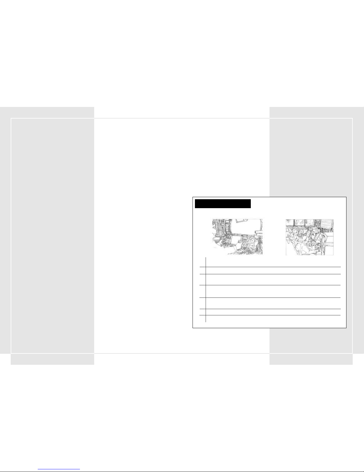
6362
8-1 RÉSUMÉ
Les communications servent à faire le lien entre des informations
clés, à changer des plans au sein de groupes, à appliquer des
ordres vitaux, à transmettre des ordres et autres informations
importantes.
Chaque VT dispose d'une radio JARC-F522 pour ses
communications.
Dans le VT du commandant de section, on trouve deux radios
JARC-F522 ou une radio JARC-F522 et une radio JARC-A232. Lorsque
vous utilisez la radio, articulez et soyez concis. Méfiez-vous
également des dispositifs d'écoute ennemis et conservez votre
identité secrète en utilisant des indicatifs lorsque vous
communiquez par radio.
8-2 CANAUX PRÉDÉFINIS
Dans la radio standard du VT, certains canaux sont prédéfinis. Ce
réglage vous permet de gagner le temps qui vous aurait été
nécessaire pour régler chaque canal, temps dont vous ne
disposez pas au cœur de la bataille. Vous pouvez avoir jusqu'à 5
canaux prédéfinis dans votre radio de VT.
8-3 PROCÉDURES DE COMMUNICATION RADIO
Pour communiquer par radio, vous devez sélectionner un canal
à l'aide d'une antenne. Appuyez ensuite sur le bouton de
communication pour commencer la transmission. La
communication est fixée à 3 choix possibles. Vous ne pouvez pas
changer la fonction de chacun de ces boutons. Les choix possibles
sont les suivants :
• Bouton de communication 1 – répondre/appeler
• Bouton de communication 2 – répéter
• Bouton de communication 3 – demande de ravitaillement
SECTION 8. TRANSMISSIONS RADIO
1. Communication panel 1 (from the main battalion Argus) begins to flash.
This signals that a message from the main battalion is coming in.
2. Set the tuner on Communications Panel 1.
3. Press Communication Button 1 (respond/call) and open a connection.
"This is Oscar 3. Argus, go ahead."
Le responsable du bataillon donne son message.
"Ici Argus. Votre division est en mauvaise situation ! Repliez-vous
immédiatement !"
5. After you hear what was said, press Communication Button 1
(respond/call).
"Oscar 3. I copy that."
6. Finish the communication.
PROCÉDURES DE COMMUNICATION
(exemple : ordre de repli)
COCKPIT :
SALLE DE CONTRÔLE DU BATAILLON PRINCIPAL :
1. Communication panel 1 (from the main battalion Argus) begins to flash.
This signals that a message from the main battalion is coming in.
2. Set the tuner on Communications Panel 1.
3. Press Communication Button 1 (respond/call) and open a connection.
"This is Oscar 3. Argus, go ahead."
4. The battalion head gives his message.
"This is Argus. Your division is in a bad spot! Retreat immediately!"
5. After you hear what was said, press Communication Button 1 "
6. If you didn’t hear the message, press Communication Button 2 (repeat).
7. Finish the communication.
Le panneau de communication 1 (du bataillon principal Argus) commence à clignoter.
Cela signale la réception d'un message provenant du bataillon principal.
Réglez le tuner sur le panneau de communication 1.
Appuyez sur le bouton de communication 1 (répondre/appeler) et ouvrez une
connexion."Ici Oscar 3. Parlez Argus."
4. The battalion head gives his message.
"This is Argus. Your division is in a bad spot! Retreat immediately!"
Lorsque vous avez entendu la réponse, appuyez sur le bouton de communication 1
(répondre/appeler). "Bien reçu, Oscar 3."
Si vous n'avez pas entendu le message, appuyez sur le bouton de communication 2 (répéter).
Terminez la communication.
7-1 ORDRES
Les sections reçoivent des ordres des bataillons et des
compagnies. Les ordres sont transmis par écrit ou par oral. Dans
la plupart des cas, la mission est précédée d'un briefing au cours
duquel les informations suivantes seront affichées :
• Objectif de la mission
• Informations sur l'ennemi
• Situation des unités alliées
• Topographie
• État du champ de bataille
• Estimation du temps de réalisation de la mission
Après cela, des officiers de tous grades vous aideront à analyser
les ordres, vous permettant d'établir le plan d'attaque de votre
section.
7-2 ANALYSE DE LA MISSION
Dès que vous recevez un ordre d'un des commandants de haut
rang (bataillon/compagnie), le commandant de division de la
section analyse la mission en fonction d'informations clés.
L'analyse de la mission comprend :
•Contenu de la mission
• Informations sur l'ennemi
• Topographie
• Armes pouvant être utilisées dans la mission courante
• Equipements et fournitures nécessaires
Avant la fin des préparatifs stratégiques, vous devez demander
votre type de VT, vos armes et vos équipements. Vous pouvez
également consulter vos objectifs de mission.
Vérifiez également que tous les membres de la section
connaissent également parfaitement les objectifs de la mission,
afin qu'ils ne commettent aucune erreur au cours de la bataille.
7-3 CHOIX DES ARMES
Un pilote de VT doit choisir ses armes pour la bataille. Ces armes
doivent être appropriées aux objectifs de la mission. Vous pouvez
transporter 3 armes principales et 3 armes secondaires, mais vous
ne pouvez pas dépasser la tolérance de poids maximale prévue
pour votre type de VT. Même si vous ne la dépassez pas, frôler la
tolérance de poids maximale n'est pas bon pour le balancier et
peut réduire grandement les performances du VT.
7-4 SÉLECTION D´ ARMES ET DE BLINDAGES
SUPPLÉMENTAIRES
Dès que vous ajoutez un blindage sur votre VT, vous vous équipez
automatiquement de missiles blindés en arme secondaire. Cela
réduit d'une unité le nombre d'armes secondaires que vous
pouvez sélectionner. Veillez à ce que le blindage associé à l'arme
ne fasse pas dépasser la tolérance de poids maximum.
7-5 CHOIX DU VT
Trois types de VT sont distribués aux sections : légers, moyens et
lourds. Vous choisissez votre VT en fonction de la nature de la
mission, mais cette décision revient en réalité au pilote. Aussi,
lorsque vous participez à des missions de largage aérien, vous ne
pouvez choisir qu'un VT de type léger.
7-6 AJOUT DE RÉSERVOIRS ET DE BLINDAGES
SUPPLÉMENTAIRES
Suivant la mission, vous pouvez choisir d'ajouter des réservoirs
ou des blindages supplémentaires. Toutefois, seul un nombre
limité de VT peut utiliser un blindage supplémentaire. Veillez
également à ce que le total final de vos blindages, réservoirs et
armes supplémentaires ne dépasse pas la tolérance de poids
maximale autorisée. Pour plus d'informations sur les relations
entre les armes secondaires et les blindages supplémentaires,
consultez les sections 7-4.
7-7 DEMANDES DE RAVITAILLEMENT
Avant de partir au combat, vous recevez le nombre estimé de
munitions nécessaires pour la mission. Toutefois, si cette
quantité s'avère insuffisante, vous serez rapidement
réapprovisionné sur le champ de bataille. Pour faciliter les
ravitaillements, demandez aux pilotes le nombre de cartouches
supplémentaires dont ils estiment avoir besoin et envoyez un
formulaire de demande de ravitaillement au bataillon de renfort
en avance.
7-8 PROVISIONS ALIMENTAIRES FIXES DES VT
Étant donné que les opérations du VT sont plutôt courtes, des
provisions de nourriture régulières sont fournies par la
compagnie d'approvisionnement. Cependant, comme il n'est pas
toujours possible d'assurer le ravitaillement en nourriture,
chaque VT dispose de rations alimentaires d'urgence équivalentes
à quatre repas. Dans les situations où le ravitaillement est
impossible, chaque commandant est chargé de leur distribution.
Une fois les rations utilisées, un commandant de grade supérieur
doit en être averti immédiatement pour assurer leur
remplacement.
7-9 EFFETS PERSONNELS DANS LE COCKPIT
Le cockpit dispose d'un compartiment spécial pour les provisions.
S'ils tiennent dans le compartiment, vous pouvez emporter des
effets personnels dans le cockpit. Toutefois, le transport d'objets
personnels doit avoir été préalablement autorisé par un officier
accompagnateur. Il est également interdit de transporter le guide
d'utilisation, strictement confidentiel, dans le VT.
SECTION 7. PRÉPARATIONS DE LA STRATÉGIE DE LA SECTION
Page 34

6564
9-1 ACCEPTER LES RAVITAILLEMENTS
Les provisions sont nécessaires à la bonne marche du VT. Trouvez
un emplacement qui vous permette de vous ravitailler au combat.
Se ravitailler en cours de bataille est une tâche périlleuse, mais
régulière. Sur le terrain de bataille, essayez de recevoir vos
ravitaillement à la nuit tombée ou à couvert uniquement. Les
ravitaillements des VT sont assurés par un hélicoptère de
ravitaillement du bataillon de ravitaillement de la division de
renfort. Vous pouvez non seulement vous ravitailler en munitions
et en carburant, mais également en blindages et en pièces de
rechange pour votre VT. Pour faciliter les ravitaillements, faites
votre demande de ravitaillement avant même de partir à la
mission.
9-2 CLASSIFICATION DES ÉQUIPEMENTS
Pour faciliter la procédure de ravitaillement, les équipements ont
été classés en 5 groupes principaux. À quelques rares exceptions
près, la majorité des pièces que vous commanderez avant la
bataille entreront dans les trois groupes suivants.
Ces fournitures font l'objet d'une commande pour chaque VT.
1. Provisions de type 1 : Alimentation
2. Provisions de type 3 : Liquides (huile, fuel, lubrifiant)
3. Provisions de type 5 : Munitions diverses
Avant de partir à la bataille, chaque pilote doit établir la liste des
équipements nécessaires et la faire approuver par son
commandant.
9-3 RAVITAILLEMENT PAR HÉLICOPTÈRE
Au cours de la bataille, les ravitaillements des VT sont acheminés
à l'aide d'un hélicoptère de ravitaillement du bataillon de
ravitaillement de la division. Lorsque vous commandez des
ravitaillements, l'hélicoptère se dirige vers la position du VT. Une
fois sur place, il s'immobilise au-dessus de la position. Le pilote
doit placer son VT sous l'hélicoptère. Le transfert du carburant et
des munitions commence alors. Vous pouvez également
transférer de nouveaux blindages et des pièces de rechange.
9-4 CHOIX ET PRÉCAUTIONS LORS DE LA
RÉCEPTION DES ÉQUIPEMENTS
Étant donné que le processus prend du temps, le VT et
l'hélicoptère sont vulnérables pendant le ravitaillement. Pour
limiter les risques d'attaque, vous devez examiner votre
environnement et rester en état d'alerte. Essayez de choisir un
site de ravitaillement aussi protégé que possible. Cette
précaution est importante, notamment pour éviter que
l'hélicoptère se fasse abattre avant d'avoir pu vous ravitailler.
9-5 OUVERTURE DU CENTRE DE
RAVITAILLEMENT
Les conditions météorologiques ou les circonstances de la
bataille peuvent empêcher l'hélicoptère d'effectuer le
ravitaillement. Pour remédier à ces situations, un centre de
ravitaillement a été mis en place derrière les lignes alliées.
L'emplacement du centre de ravitaillement est déterminé avant la
bataille, conformément à ces principes :
1. Il possède une quantité d'espace suffisante pour stocker les
ravitaillements nécessaires.
2. Un chemin convenable relie les lignes de front aux lignes
arrières.
3. Il n'est pas visible par l'ennemi.
4. Il est protégé de la puissance de feu ennemie.
Le centre de ravitaillement est implanté uniquement dans les
endroits où la ligne de front est fixe et où un camp couvre la
zone. Il faut donc envisager son utilisation comme
exceptionnelle.
Vous devez vous ravitailler à l'aide de l'hélicoptère dès que cela
est possible.
SECTION 9. RAVITAILLEMENT
SCHÉMA DE RAVITAILLEMENT DU VT PAR HÉLICOPTÈRE
Vol normal
Ravitaillement possible
8-4 ENVOI D ´UN MESSAGE
1. Choisissez qui vous allez appeler en composant
le canal de cette personne sur le tuner.
2. Appuyez sur le bouton de communication 1
(appeler/répondre) pour passer l'appel.
3. La personne appelée répond.
4. Après avoir vérifié qu'il s'agissait de la personne
voulue, formulez votre demande.
5. L'interlocuteur vérifiera ce que vous avez
demandé.
6. Fin de l'appel.
8-5 RÉCEPTION D´UN MESSAGE
1. Lorsqu'un message arrive, votre panneau de
communication se met à clignoter. Réglez le
tuner sur le canal qui clignote. En faisant cela,
vous pouvez entendre le message de l'autre
personne.
2. Appuyez sur le bouton de communication 1
(appeler/répondre) et répondez à l'appel.
3. L'autre personne verra que vous avez répondu
et formulera son message.
4. Lorsque vous avez entendu le message, appuyez
sur le bouton de communication 1
(appeler/répondre) pour terminer l'appel.
8-6 RÉPÉTITION DU MESSAGE
Lorsque vous ne comprenez pas ce que dit votre
interlocuteur, appuyez sur le bouton de
communication 2 pour lui demander de répéter son
message. Vous pouvez faire une demande dès que le
panneau de communication clignote (indiquant que
les lignes sont ouvertes). Lorsque vous appuyez sur
le bouton de communication 1, la communication
se terminera et la ligne sera fermée.
LISTE DES INDICATIFS (impression 2080)
Groupe Indicatif Nom anglais Nom formel
Joueur(Section) Oscar 3 Oscar 3 7 ème division spéciale de Panzers, 34 ème bataillon blindé spécial, 6 ème compagnie blindée spéciale, 1 ère section 3 ème VT
Commandant Oscar 1 Oscar 1 7 ème division spéciale de Panzers, 34 ème bataillon blindé spécial, 6 ème compagnie blindée spéciale, 1 ère section 1 er VT
Bataillon principal Argus Argus 7 ème division spéciale de Panzers, 34 ème bataillon principal blindé spécial
Ravitaillement Responsable Responsable 7 ème division spéciale de Panzers, bataillon de ravitaillement
LISTE DES INDICATIFS (impression 2082)
Joueur(Section) Xray 1 Xray 1 7 ème division spéciale de Panzers, 34 ème bataillon blindé spécial, 6 ème compagnie blindée spéciale, 1 ère section 1 er VT
Ailier 1 Xray 2 Xray 2 7 ème division spéciale de Panzers, 34 ème bataillon blindé spécial, 6 ème compagnie blindée spéciale, 1 ère section 2 ème VT
Ailier 2 Xray 3 Xray 3 7 ème division spéciale de Panzers, 34 ème bataillon blindé spécial, 6 ème compagnie blindée spéciale, 1 ère section 3 ème VT
Bataillon principal Argus Argus 7 ème division spéciale de Panzers, 34 ème bataillon principal blindé spécial
Ravitaillement Responsable Responsable 7 ème division spéciale de Panzers, bataillon de ravitaillement
Espion Veuve noire Veuve noire ??????????
BOUTONS DE COMMUNICATION (2082)
Bouton Com 1 Bouton Com 2 Bouton Com 3 Bouton Com 4 Bouton Com 5
Appeler/Répondre Répéter Demander ravitaillement
BOUTONS DE COMMUNICATION (2080)
Bouton Com 1 Bouton Com 2 Bouton Com 3 Bouton Com 4 Bouton Com 5
Appeler/Répondre Répéter Demander ravitaillement Demander soutien
CONFIGURATION DES CANAUX DU PANNEAU DE COMMUNICATION
Panneau Com 1 Panneau Com 2 Panneau Com 3 Panneau Com 4 Panneau Com 5
MIS00
MIS01
MIS02
MIS03 Commandement Ravitaillement Commandant de VT
MIS04 Commandement Ravitaillement Commandant de VT
MIS05 Commandement Ravitaillement Commandant de VT
MIS06 Commandement Ravitaillement Commandant de VT
MIS07 Commandement Ravitaillement Commandant de VT
MIS08 Commandement Ravitaillement Commandant de VT
MIS09 Commandement Ravitaillement Commandant de VT
MIS10 Commandement Ravitaillement Commandant de VT
MIS11 Commandement Ravitaillement Commandant de VT
MIS12 Commandement Ravitaillement Ailier 1 Ailier 2 Ailier 1/2
MIS13 Commandement Ravitaillement Ailier 1 Ailier 2 Ailier 1/2
MIS14 Commandement Ravitaillement Ailier 1 Ailier 2 Ailier 1/2
MIS15 Commandement Ravitaillement Ailier 1 Ailier 2 Ailier 1/2
MIS16 Commandement Ravitaillement Ailier 1 Ailier 2 Ailier 1/2
MIS17 Commandement Ravitaillement Division Espionnage
MIS18 Commandement Ravitaillement Ailier 1 Ailier 2 Ailier 1/2
MIS19 Commandement Ravitaillement Ailier 1 Ailier 2 Ailier 1/2
MIS20 Commandement Ravitaillement
MIS21 Commandement Ravitaillement Ailier 1 Ailier 2 Ailier 1/2
MIS22 Commandement Ravitaillement Ailier 1 Ailier 2 Ailier 1/2
MIS23 Commandement Ravitaillement Ailier 1 Ailier 2 Ailier 1/2
Page 35

6766
10-1 DEVOIRS DU COMMANDANT
Le devoir d'un commandant est de donner des ordres à ses
troupes et de remplir la mission qui lui a été assignée. Les
commandants gagnent la confiance de leurs troupes en faisant
preuve de leur sens du commandement et de leur capacité à
assurer la stabilité et la cohésion de leur division. Ces qualités
leur permettent d'améliorer leurs aptitudes et compétences.
10-2 QUALITÉS NÉCESSAIRES À UN
COMMANDANT
Un commandant a la responsabilité de mener à bien sa mission
et est responsable de ses troupes. Le commandant doit bien
connaître les hommes, les équipements, les tactiques et la
stratégie tout en étant un pilote de VT hors-pair. Toutefois, la
responsabilité la plus importante du commandant consiste à
gagner la confiance de ses troupes, à leur servir de modèle et à
accomplir sa mission. Il doit savoir se sortir de situations très
délicates. Au combat, il doit garder la tête froide et lucide pour
prendre les décisions qui s'imposent. Il doit être vif et incisif. Si
le commandant hésite au combat, ses troupes perdent confiance
et prennent peur. Pour toutes ces raisons, il doit analyser sa
mission avec soin et être capable de panifier l'avenir seul.
10-3 ORDRES EN COURS DE BATAILLE
Le commandant de section doit faire comprendre à chacun sa
mission, son rôle et les règles de l'engagement. Il doit
commander ses troupes de manière à obtenir le meilleur d'euxmêmes. Sur cette base, il peut donner des ordres simples,
rendant les stratégies de bataille plus simples à appliquer. Le
commandant de section doit communiquer ses ordres à l'aide du
bouton de communication pré-réglé 4 ou 5, comme le prévoit le
règlement. Les communications s'en trouveront facilitées. 4
ordres différents peuvent être prédéfinis. D'après le plan de
bataille, le commandant de section doit en choisir deux.
Il y a quatre ordres clés (parmi lesquels le commandant de
section choisit deux) :
1. Separate and Disengage
Ordre de séparation et d'éloignement du combat. Dans le cas
où un de ses VT est endommagé, la section doit essayer de
s'éloigner aussi vite que possible. Le chef de la section a la
responsabilité d'exécuter ses ordres tout en protégeant ses
hommes. Il doit donc faire son possible pour maintenir ses
hommes en vie.
2. Backup
La section doit utiliser son VT pour soutenir une autre
troupe, en cas de coopération avec d'autres forces, d'entrée
en contact avec l'ennemi, etc. L'objectif est d'optimiser la
puissance d'attaque de la section. Le commandant de la
section connaît parfaitement les règles et les règlements
pour les avoir appliqués à l'entraînement et au combat. Il
doit également élever le niveau d'entraînement de ses
troupes.
3. Attack
C'est l'ordre d'attaquer l'objectif principal. Le commandant
de section émet cet ordre si les circonstances l'exigent. La
caractéristique la plus importante ici est de servir d'exemple
pour les troupes, mais atteindre l'objectif est le but principal
de la section tout entière. Dans les situations où l'on
poursuit plusieurs cibles, cette commande facilite
l'accomplissement de la mission.
4. Disperse
Dès que vous sentez l'ennemi se rapprocher, vous pouvez
émettre un ordre de dispersion de vos troupes. Cet ordre
peut être extrêmement utile lorsque la topographie du
champ de bataille l'exige ou lorsque vous devez effectuer
des recherches dans de vastes zones.
SECTION 10. COMMANDEMENT
WHEN USING THE PLASMA TORCH
ORDRE DE SECTION : SEPARATE AND
DISENGAGE
ORDRE DE SECTION : BACKUP
ORDRE DE SECTION : ATTACK
ORDRE DE SECTION : DISPERSE
Ailier 1
Ailier 2
Commandant de section
Ailier 1
Ailier 2
Commandant de section
Ailier 1
Ailier 2
Commandant de section
Ailier 1
Ailier 2
Commandant de section
Page 36

6968
WHEN USING THE PLASMA TORCH
ANNEXE TECHNIQUE
COCKPIT : 1 ère GÉNÉRATION
Voyant d'alarme signalant un obstacle en face
Multi-moniteur
Arme secondaire 1
Utilisations restantes de l'arme secondaire 1
Arme principale 1
Chargeurs restants de l'arme principale 1
Munitions restantes de l'arme principale 1
Voyant d'alarme signalant un incendie à bord
Voyant d'alarme signalant un obstacle à droite
Voyant d'alarme signalant un obstacle à gauche
Arme principale 2
Chargeurs restants de l'arme principale 2
Munitions restantes de l'arme principale 2
Arme principale 3
Chargeurs restants de l'arme principale 3
Munitions restantes de l'arme principale 3
Voyants Com 1-5
Compteur Batterie
Compte-tours Moteur
Compteur de vitesse
Compteur d'énergie principal
Voyant de dommage
Moniteur
secondaire
Voyant de
déplacement
Compteur de vitesse numérique
Surmultipliée limite du
balancier
Tuner
Arme secondaire 2
Utilisations restantes de l'arme secondaire 2
Compteur du réservoir secondaire 1
Réservoir secondaire 1
fixé ou non
Réservoir secondaire 1 utilisé
Compteur du réservoir secondaire 2
Réservoir secondaire 2
fixé ou non
Réservoir secondaire 2 utilisé
Arme secondaire 3
Utilisations restantes de l'arme secondaire 3
Utilisations restantes des paillettes
WHEN USING THE PLASMA TORCH
COCKPIT : 2 ème GÉNÉRATION
Voyant d'alarme signalant
un obstacle en face
Surmultipliée limite du balancier
Multi-moniteur
Nom de l'arme principale
Chargeurs restants de l'arme principale
Munitions restantes de l'arme principale
Voyant d'alarme signalant un incendie à bord
Voyant d'alarme signalant un incendie à bord
Voyant d'alarme signalant
un obstacle à droite
Voyant d'alarme signalant
un obstacle à gauche
Voyants com 1-5
Compteur Batterie
Voyant Surmultipliée
Compte-tours Moteur
Compteur de vitesse
Compteur d'énergie principal
Voyant de
dommages
Moniteur secondaire
Voyant de
vitesse
Compteur de vitesse numérique
Tuner
Arme secondaire 1
Utilisations restantes de l'arme secondaire 1
Compteur du réservoir secondaire
Réservoir secondaire 1 utilisé
Disponibilité
du réservoir
secondaire 1
Réservoir secondaire 2 utilisé
Disponibilité du
réservoir secondaire 2
Utilisations restantes des paillettes
MONITEUR PRINCIPAL : 2 ème GÉNÉRATION
DURÉE . . . . . . . . . . . . . . . . . . . . . . . Durée restante
FSS . . . . . . . . . . . . . . . . . . . . . . . . . Indique que le système FSS fonctionne
SUB . . . . . . . . . . . . . . . . . . . . . . . . . Infos Arme secondaire
RELOAD – Vous êtes en cours de rechargement
HIT/MISS – Vous avez touché ou manqué avec votre arme secondaire
INFOS RAVITAILLEMENT . . . . . . . . . . . . STAND BY – Préparation au ravitaillement
REFUEL – Ravitaillement
COMPLETE – Ravitaillement terminé
DESTROYED . . . . . . . . . . . . . . . . . . . . Ennemi détruit
MISSION COMPLETE . . . . . . . . . . . . . . Indique la pourcentage de réalisation de la mission
MAIN . . . . . . . . . . . . . . . . . . . . . . . . Infos Arme principale
RELOAD – Vous êtes en cours de rechargement
HIT/MISS – Vous avez touché ou manqué avec votre arme principale
WARN . . . . . . . . . . . . . . . . . . . . . . . Vous avertit que l'ennemi est verrouillé sur votre VT
SHOT . . . . . . . . . . . . . . . . . . . . . . . . Indique que l'ennemi a tiré une arme dépourvue de système de guidage sur vous
BOMB . . . . . . . . . . . . . . . . . . . . . . . Vous avertit que des bombes à trajectoire incurvée se dirigent vers vous
MSSL . . . . . . . . . . . . . . . . . . . . . . . . Vous indique qu'un missile guidé se dirige vers vous
NML . . . . . . . . . . . . . . . . . . . . . . . . Fonctionnement normal (sans surmultipliée)
OVRD . . . . . . . . . . . . . . . . . . . . . . . . Vous êtes en vitesse surmultipliée
HEAT . . . . . . . . . . . . . . . . . . . . . . . . Indique que la batterie a surchauffé
BLNC . . . . . . . . . . . . . . . . . . . . . . . . Indique que le balancier atteint sa limite
AREA . . . . . . . . . . . . . . . . . . . . . . . . Indique que vous quittez le champ de bataille désigné
x 1.00 . . . . . . . . . . . . . . . . . . . . . . . Taux d'agrandissement de la caméra principale
ANGLE DE DÉPRESSION/D'ÉLÉVATION . . . Indique l'angle de la caméra
COMPASS . . . . . . . . . . . . . . . . . . . . . Indique la direction vers laquelle vous vous dirigez
MONITEUR PRINCIPAL : 1 ère GÉNÉRATION
DURÉE . . . . . . . . . . . . . . . . . . . . . . . . . . Durée restante
FSS . . . . . . . . . . . . . . . . . . . . . . . . . . . . Indique que le système FSS fonctionne
SUB . . . . . . . . . . . . . . . . . . . . . . . . . . . Infos Arme secondaire
RELOAD – Vous êtes en cours de rechargement
HIT/MISS – Vous avez touché ou manqué avec votre arme secondaire
SUPPLY INFO . . . . . . . . . . . . . . . . . . . . . STAND BY – Préparation au ravitaillement
REFUEL – Ravitaillement
COMPLETE – Ravitaillement terminé
DESTROYED . . . . . . . . . . . . . . . . . . . . . . Ennemi détruit
MISSION COMPLETE . . . . . . . . . . . . . . . . . Indique la pourcentage de réalisation de la mission
MAIN . . . . . . . . . . . . . . . . . . . . . . . . . . Infos Arme principale
RELOAD – Vous êtes en cours de rechargement
HIT/MISS – Vous avez touché ou manqué avec votre arme principale
WARN . . . . . . . . . . . . . . . . . . . . . . . . . . Vous avertit que l'ennemi est verrouillé sur votre VT
SHOT . . . . . . . . . . . . . . . . . . . . . . . . . . Indique que l'ennemi a tiré une arme dépourvue de système de guidage sur vous
BOMB . . . . . . . . . . . . . . . . . . . . . . . . . . Vous avertit que des bombes à trajectoire incurvée se dirigent vers vous
MSSL . . . . . . . . . . . . . . . . . . . . . . . . . . . Vous indique qu'un missile guidé se dirige vers vous
NML . . . . . . . . . . . . . . . . . . . . . . . . . . . Fonctionnement normal (sans surmultipliée)
OVRD . . . . . . . . . . . . . . . . . . . . . . . . . . Vous êtes en vitesse surmultipliée
HEAT . . . . . . . . . . . . . . . . . . . . . . . . . . . Indique que la batterie a surchauffé
BLNC . . . . . . . . . . . . . . . . . . . . . . . . . . . Indique que le balancier atteint sa limite
AREA . . . . . . . . . . . . . . . . . . . . . . . . . . Indique que vous quittez le champ de bataille désigné
4.63 . . . . . . . . . . . . . . . . . . . . . . . . . . . Taux d'agrandissement de la caméra principale
ANGLE DE DÉPRESSION/D'ÉLÉVATION . . . . . Indique l'angle de la caméra
COMPASS . . . . . . . . . . . . . . . . . . . . . . . . Indique la direction vers laquelle vous vous dirigez
Page 37

7170
GARANTIE LIMITÉE POUR VOTRE COPIE DU JEU XBOX (LE « JEU »)
Garantie. Microsoft Corporation (« Microsoft ») garantit que pendant
une période de quatre-vingt-dix (90) jours à compter de la date de
première acquisition, le Jeu fonctionnera pour l’essentiel
conformément au manuel qui l’accompagne. Cette garantie limitée ne
sera pas applicable si le dysfonctionnement du Jeu résulte d'un
accident, d’un usage ayant entraîné une détérioration, d’un virus ou
d’une utilisation inappropriée. Microsoft ne fournit aucune autre
garantie concernant ce Jeu.
Vos recours. Si, au cours de la période de quatre-vingt-dix (90) jours,
vous découvrez que le Jeu couvert par cette garantie ne fonctionne pas
correctement, retournez-le à votre détaillant accompagné d’une copie
du justificatif d’achat initial. Le détaillant aura le choix (a) de réparer ou
de remplacer le Jeu sans frais supplémentaire, ou (b) de vous
rembourser le prix que vous avez payé pour le Jeu. Tout Jeu de
remplacement sera garanti soit pour la période de garantie initiale
restant à courir, soit pendant trente (30) jours à compter de la date de
réception, la période la plus longue étant applicable. Dans la mesure où
les dommages causés au Jeu résultent d’une négligence de votre part,
la société Microsoft ne pourra en être tenue responsable.
Protection légale. Vous pouvez bénéficier, à l’encontre de votre
détaillant, de tous les droits auxquels on ne peut déroger par contrat.
Ces droits ne sont pas affectés par la présente garantie limitée de
Microsoft.
SI VOUS N’AVEZ PAS ACQUIS LE JEU POUR VOTRE USAGE
PERSONNEL (C’EST À DIRE, SI VOUS N’AVEZ PAS AGI EN TANT QUE
CONSOMMATEUR)
Les conditions suivantes s’appliquent dans toute la mesure permise par
la loi en vigueur.
Aucune autre garantie. Microsoft et ses fournisseurs excluent toute
autre garantie, expresse ou implicite, relative au Jeu et au manuel qui
l’accompagne.
Limitation de responsabilité. Ni Microsoft ni ses fournisseurs ne
pourront être tenus responsables de tout dommage, quel qu’il soit,
découlant ou lié, de quelque façon que ce soit, à l’utilisation ou à
l’impossibilité d’utiliser le Jeu, même si Microsoft ou ses fournisseurs
ont été avisés de la possibilité de tels dommages. Dans tous les cas,
l’entière responsabilité de Microsoft et de ses fournisseurs est limitée
au prix que vous avez effectivement payé pour le Jeu.
Vous pouvez adresser vos questions relatives à la garantie à votre
détaillant ou à Microsoft à l’adresse suivante :
Microsoft Ireland Operations Limited
Sandyford Industrial Estate
Blackthorn Road
Dublin 18
Irlande
Les informations contenues dans ce document, y compris les références à des URL ou à
d'autres sites Web Internet, peuvent faire l'objet de modifications sans préavis. Sauf
mention contraire, les noms de sociétés, les organisations, les produits, les personnes et
les événements décrits dans ce document sont fictifs et toute ressemblance à une
société, une organisation, un produit, une personne ou un événement réels ne serait que
pure coïncidence. Il incombe à l'utilisateur de respecter toutes les lois applicables en
matière de droits d'auteur. Sans limitation des droits issus des droits d'auteur, aucune
partie de ce document ne peut être reproduite, stockée ou incluse dans un système de
récupération de données, ou transmise à quelque fin ou par quelque moyen que ce soit
(électronique, mécanique, photocopie, enregistrement ou autre) sans l'autorisation
expresse et écrite de Microsoft Corporation.
Les produits mentionnés dans ce document peuvent faire l'objet de brevets, de dépôts de
brevets en cours, de marques, de droits d'auteur ou d'autres droits de propriété
intellectuelle et industrielle de Microsoft. Sauf stipulation expresse contraire d'un contrat
de licence écrit de Microsoft, la fourniture de ce document n'a pas pour effet de vous
concéder une licence sur ces brevets, marques, droits d'auteur ou autres droits de
propriété intellectuelle.
© 2003 Microsoft Corporation. Tous droits réservés.
Microsoft, Xbox et les logos Xbox sont soit des marques de Microsoft Corporation, soit
des marques déposées de Microsoft Corporation aux États-Unis d’Amérique et/ou dans
d'autres pays.
Fabriqué sous licence de Dolby Laboratories.
WHEN USING THE PLASMA TORCH
COCKPIT : 3 ème GÉNÉRATION
Voyant d'alarme
signalant un obstacle
en face
Surmultipliée limite du
balancier
Multi-moniteur
Nom de l'arme principale
Chargeurs restants de l'arme principale
Munitions restantes de l'arme principale
Voyant d'alarme signalant un incendie à bord
Voyant d'alarme signalant un
incendie à bord
Voyant d'alarme
signalant un
obstacle à droite
Voyant d'alarme
signalant un
obstacle à gauche
Voyants com 1-5
Compteur Batterie
Voyant Surmultipliée
Voyant Surmultipliée
Compte-tours Moteur
Compteur de
vitesse
Compteur d'énergie principal
Voyant de
dommages
Moniteur secondaire
Voyant de vitesse
Compteur de vitesse numériquer
Tuner
Arme secondaire 1
Utilisations restantes de l'arme secondaire 1
Compteur du réservoir secondaire 1
Disponibilité du
réservoir
secondaire 1
Compteur du réservoir
secondaire 2
Disponibilité du
réservoir
secondaire 2
Utilisations restantes des paillettes
MONITEUR PRINCIPAL : 3 ème GÉNÉRATION
DURÉE . . . . . . . . . . . . . . . . . . . . . . . Durée restante
FSS . . . . . . . . . . . . . . . . . . . . . . . . . Indique que le système FSS fonctionne
SUB . . . . . . . . . . . . . . . . . . . . . . . . . Infos Arme secondaire
RELOAD – Vous êtes en cours de rechargement
HIT/MISS – Vous avez touché ou manqué avec votre arme secondaire
INFOS RAVITAILLEMENT . . . . . . . . . . . .STAND BY – Préparation au ravitaillement
REFUEL – Ravitaillement
COMPLETE – Ravitaillement terminé
DESTROYED . . . . . . . . . . . . . . . . . . . Ennemi détruit
MISSION COMPLETE . . . . . . . . . . . . . . Indique la pourcentage de réalisation de la mission
MAIN . . . . . . . . . . . . . . . . . . . . . . . . Infos Arme principale
RELOAD – Vous êtes en cours de rechargement
HIT/MISS – Vous avez touché ou manqué avec votre arme principale
WARN . . . . . . . . . . . . . . . . . . . . . . . Vous avertit que l'ennemi est verrouillé sur votre VT
SHOT . . . . . . . . . . . . . . . . . . . . . . . . Indique que l'ennemi a tiré une arme dépourvue de système de guidage sur vous
BOMB . . . . . . . . . . . . . . . . . . . . . . . Vous avertit que des bombes à trajectoire incurvée se dirigent vers vous
MSSL . . . . . . . . . . . . . . . . . . . . . . . . Vous indique qu'un missile guidé se dirige vers vous
NML . . . . . . . . . . . . . . . . . . . . . . . . Fonctionnement normal (sans surmultipliée)
OVRD . . . . . . . . . . . . . . . . . . . . . . . Vous êtes en vitesse surmultipliée
HEAT . . . . . . . . . . . . . . . . . . . . . . . . Indique que la batterie a surchauffé
BLNC . . . . . . . . . . . . . . . . . . . . . . . . Indique que le balancier atteint sa limite
AREA . . . . . . . . . . . . . . . . . . . . . . . . Indique que vous quittez le champ de bataille désigné
x 1.00 . . . . . . . . . . . . . . . . . . . . . . . Taux d'agrandissement de la caméra principale
ANGLE DE DÉPRESSION/D'ÉLÉVATION . . .Indique l'angle de la caméra
COMPASS . . . . . . . . . . . . . . . . . . . . . Indique la direction vers laquelle vous vous dirigez
Page 38

CONTROLLER-EINSTELLUNG . . . . . . . . . . . . . . . . . . . . . . . . . . . . . . . . . . . 74
Vorsichtsmaßnahmen . . . . . . . . . . . . . . . . . . . . . . . . . . . . . . . . . . . 74
Problembehandlung . . . . . . . . . . . . . . . . . . . . . . . . . . . . . . . . . . . . 74
Montage der rechten Einheit . . . . . . . . . . . . . . . . . . . . . . . . . . . . . . 74
Montage der linken Einheit . . . . . . . . . . . . . . . . . . . . . . . . . . . . . . . 74
ABSCHNITT 1. VT-KONZEPT UND SPEZIALPANZERDIVISION . . . . . . . . . . . . 76
1-1 VT-Konzept . . . . . . . . . . . . . . . . . . . . . . . . . . . . . . . . . . . . . . . . . 76
1-2 Grundlagen für den militärischen Einsatz des VT . . . . . . . . . . . . 76
1-3 Pflichten einer Spezialpanzereinheit . . . . . . . . . . . . . . . . . . . . . 76
1-4 Zusammensetzung einer Spezialpanzerdivision . . . . . . . . . . . . . 76
1-5 VT Platoon-Einsatz . . . . . . . . . . . . . . . . . . . . . . . . . . . . . . . . . . . 76
ABSCHNITT 2. VT-ZUSAMMENFASSUNG . . . . . . . . . . . . . . . . . . . . . . . . . . . 77
2-1 VT-Basisteile . . . . . . . . . . . . . . . . . . . . . . . . . . . . . . . . . . . . . . . . 77
2-2 VT-Betriebssystem . . . . . . . . . . . . . . . . . . . . . . . . . . . . . . . . . . . 77
2-3 VT-Typen . . . . . . . . . . . . . . . . . . . . . . . . . . . . . . . . . . . . . . . . . . 78
2-4 Bewegung . . . . . . . . . . . . . . . . . . . . . . . . . . . . . . . . . . . . . . . . . . 78
2-5 Kraftstofftank und Ersatztanks . . . . . . . . . . . . . . . . . . . . . . . . . 78
2-6 Kraftstoffverbrauch und geschätzte Einsatzdauer . . . . . . . . . . . 78
2-7 Schutzpanzerung . . . . . . . . . . . . . . . . . . . . . . . . . . . . . . . . . . . . 78
2-8 Hauptwaffen und Unterwaffen . . . . . . . . . . . . . . . . . . . . . . . . . 78
2-9 Maximal zulässiges Waffengewicht . . . . . . . . . . . . . . . . . . . . . . 78
2-10 Waffenarsenal des VT . . . . . . . . . . . . . . . . . . . . . . . . . . . . . . . 79
2-11 Zielausrichtung von Waffen mit gekrümmten
Geschossflugbahnen auf der Kriegskarte . . . . . . . . . . . . . . . . . 80
2-12 Kurzzünder . . . . . . . . . . . . . . . . . . . . . . . . . . . . . . . . . . . . . . . 80
2-13 Verteidigung mithilfe von Düppeln . . . . . . . . . . . . . . . . . . . . . . 80
ABSCHNITT 3. SONDERFUNKTIONEN
DURCH COOS DER 2. GENERATION . . . . . . . . . . . . . . . . . . . . . . . . . . . . . . 84
3-1 Zusätze für COOS der 2. Generation . . . . . . . . . . . . . . . . . . . . . . 84
3-2 FSS-Funktion (Zielabschätzendes Feuersystem) . . . . . . . . . . . . . 84
3-3 Overdrive-Funktion . . . . . . . . . . . . . . . . . . . . . . . . . . . . . . . . . . 84
3-4 Tarnfunktion . . . . . . . . . . . . . . . . . . . . . . . . . . . . . . . . . . . . . . . 84
3-5 Lenkwaffen . . . . . . . . . . . . . . . . . . . . . . . . . . . . . . . . . . . . . . . . 84
ABSCHNITT 4. VT-STEUERUNGEN . . . . . . . . . . . . . . . . . . . . . . . . . . . . . . . 85
4-1 Startsequenz . . . . . . . . . . . . . . . . . . . . . . . . . . . . . . . . . . . . . . . 85
4-2 Anhalten des VT während des Starts . . . . . . . . . . . . . . . . . . . . . 85
Basissteuerungen . . . . . . . . . . . . . . . . . . . . . . . . . . . . . . . . . . . . . . 86
4-3 Bewegen und Anhalten . . . . . . . . . . . . . . . . . . . . . . . . . . . . . . . 86
4-4 Beschleunigen und Bremsen . . . . . . . . . . . . . . . . . . . . . . . . . . . 86
4-5 Drehung . . . . . . . . . . . . . . . . . . . . . . . . . . . . . . . . . . . . . . . . . . 86
4-6 Overdrive . . . . . . . . . . . . . . . . . . . . . . . . . . . . . . . . . . . . . . . . . 86
4-7 Gleitschrittfunktion . . . . . . . . . . . . . . . . . . . . . . . . . . . . . . . . . 86
4-8 Gleitschritt-Funktionseinschränkungen . . . . . . . . . . . . . . . . . . . 86
4-9 Gleitschritt-Kippstabilisator . . . . . . . . . . . . . . . . . . . . . . . . . . . 86
4-10 Abschaltfunktion . . . . . . . . . . . . . . . . . . . . . . . . . . . . . . . . . . . 86
4-11 Manipulator-Steuerungen . . . . . . . . . . . . . . . . . . . . . . . . . . . . . 87
VT-Monitor . . . . . . . . . . . . . . . . . . . . . . . . . . . . . . . . . . . . . . . . . . . 88
4-12 Hauptkamerawechsel . . . . . . . . . . . . . . . . . . . . . . . . . . . . . . . . 88
4-13 Hauptkamera Schmutz und Staub . . . . . . . . . . . . . . . . . . . . . . . 88
4-14 Sub-Monitor-Funktionen . . . . . . . . . . . . . . . . . . . . . . . . . . . . . 89
4-15 Nachtsichtausrüstung . . . . . . . . . . . . . . . . . . . . . . . . . . . . . . . . 89
JCS (Vollständiges Befehlssystem) . . . . . . . . . . . . . . . . . . . . . . . . . . 89
4-16 JCS Zusammenfassung . . . . . . . . . . . . . . . . . . . . . . . . . . . . . . . 89
4-17 Mehrfachmonitordarstellung . . . . . . . . . . . . . . . . . . . . . . . . . . 90
4-18 Auf dem Mehrfachmonitor dargestellte Informationen . . . . . . 90
Massnahmen in Notfall . . . . . . . . . . . . . . . . . . . . . . . . . . . . . . . . . . . . . . . 91
4-19 Evakuierungsvorbereitungen . . . . . . . . . . . . . . . . . . . . . . . . . . 91
4-20 Abspreng-Notschalter . . . . . . . . . . . . . . . . . . . . . . . . . . . . . . . 91
4-21 Vorgehensweisen bei der Notrettung auf Flüssen und Seen . . . 91
4-22 Feuer im Rumpf . . . . . . . . . . . . . . . . . . . . . . . . . . . . . . . . . . . . 91
ABSCHNITT 5. VT-ANGRIFF . . . . . . . . . . . . . . . . . . . . . . . . . . . . . . . . . . . . 92
5-1 Zielen und Schießen mit den Waffen . . . . . . . . . . . . . . . . . . . . . 92
5-2 Zielerfassungsfunktion . . . . . . . . . . . . . . . . . . . . . . . . . . . . . . . 92
5-3 Zielen im Nahkampf . . . . . . . . . . . . . . . . . . . . . . . . . . . . . . . . . 92
5-4 FSS (Zielabschätzendes Feuersystem) . . . . . . . . . . . . . . . . . . . . . 93
5-5 Schussweiten der verschiedenen Waffen . . . . . . . . . . . . . . . . . . 93
5-6 Hinweise zum Feuern innerhalb der effektiven Zieldistanz . . . . 93
5-7 Ausnutzung der effektiven Zieldistanz . . . . . . . . . . . . . . . . . . . . 94
5-8 Bodenabwehrangriff . . . . . . . . . . . . . . . . . . . . . . . . . . . . . . . . . 94
5-9 Wechsel der Waffe . . . . . . . . . . . . . . . . . . . . . . . . . . . . . . . . . . 94
5-10 Nachladen der Magazinwaffen . . . . . . . . . . . . . . . . . . . . . . . . . 94
ABSCHNITT 6. VT-BEWEGUNGEN . . . . . . . . . . . . . . . . . . . . . . . . . . . . . . . 95
6-1 Allgemeines . . . . . . . . . . . . . . . . . . . . . . . . . . . . . . . . . . . . . . . . 95
6-2 Ausnutzung von Wetter und Topografie . . . . . . . . . . . . . . . . . . 95
STEEL BATTALION-CONTROLLER-KONFIGURATION . . . . . . . . . . . . . . . . . . 96
ABSCHNITT 7. PLATOON-STRATEGIEVORBEREITUNGEN . . . . . . . . . . . . . . . 98
7-1 Befehle . . . . . . . . . . . . . . . . . . . . . . . . . . . . . . . . . . . . . . . . . . . 98
7-2 Missionsanalyse . . . . . . . . . . . . . . . . . . . . . . . . . . . . . . . . . . . . 98
7-3 Auswahl der Waffen . . . . . . . . . . . . . . . . . . . . . . . . . . . . . . . . . 98
7-4 Auswahl zusätzlicher Panzerungen und Unterwaffen . . . . . . . . . 98
7-5 Auswahl des VT . . . . . . . . . . . . . . . . . . . . . . . . . . . . . . . . . . . . . 98
7-6 Anbringen zusätzlicher Kraftstofftanks und Panzerungen . . . . . 98
7-7 Nachschubanforderungen . . . . . . . . . . . . . . . . . . . . . . . . . . . . . 98
7-8 Festgelegter VT-Lebensmittelproviant . . . . . . . . . . . . . . . . . . . . 98
7-9 Mitnahme von persönlicher Habe in das Cockpit . . . . . . . . . . . 98
ABSCHNITT 8. FUNKVERKEHR
8-1 Zusammenfassung . . . . . . . . . . . . . . . . . . . . . . . . . . . . . . . . . . . 99
8-2 Voreingestellte Kanäle . . . . . . . . . . . . . . . . . . . . . . . . . . . . . . . 99
8-3 Abläufe im Funkverkehr . . . . . . . . . . . . . . . . . . . . . . . . . . . . . . 99
8-4 Senden einer Meldung . . . . . . . . . . . . . . . . . . . . . . . . . . . . . . 100
8-5 Empfangen einer Meldung . . . . . . . . . . . . . . . . . . . . . . . . . . . . 100
8-6 Wiederholen der Meldung . . . . . . . . . . . . . . . . . . . . . . . . . . . 100
ABSCHNITT 9. NACHSCHUB . . . . . . . . . . . . . . . . . . . . . . . . . . . . . . . . . . . 101
9-1 Aufnahme von Nachschub . . . . . . . . . . . . . . . . . . . . . . . . . . . . . 101
9-2 Klassifizierung von Nachschub . . . . . . . . . . . . . . . . . . . . . . . . . 101
9-3 Nachschub per Versorgungshubschrauber . . . . . . . . . . . . . . . . 101
9-4 Möglichkeiten und Vorsichtsmaßnahmen
bei der Aufnahme von Nachschub . . . . . . . . . . . . . . . . . . . . . . 101
9-5 Errichtung des Nachschubverteilungszentrums . . . . . . . . . . . . . 101
ABSCHNITT 10. FÜHRUNG . . . . . . . . . . . . . . . . . . . . . . . . . . . . . . . . . . . . 102
10-1 Führungspflichten . . . . . . . . . . . . . . . . . . . . . . . . . . . . . . . . . . 102
10-2 Erforderliche Qualitäten eines Commanders . . . . . . . . . . . . . . 102
10-3 Befehlserteilung während des Kampfes . . . . . . . . . . . . . . . . . 102
TECHNISCHER ANHANG . . . . . . . . . . . . . . . . . . . . . . . . . . . . . . . . . . . . . . 104
Cockpit: 1. Generation . . . . . . . . . . . . . . . . . . . . . . . . . . . . . . . . . . 104
Hauptmonitordarstellung: 1. Generation . . . . . . . . . . . . . . . . . . . . 104
Cockpit: 2. Generation . . . . . . . . . . . . . . . . . . . . . . . . . . . . . . . . . . 105
Hauptmonitordarstellung: 2. Generation . . . . . . . . . . . . . . . . . . . . 105
Cockpit: 3. Generation . . . . . . . . . . . . . . . . . . . . . . . . . . . . . . . . . . 106
Hauptmonitordarstellung: 3. Generation . . . . . . . . . . . . . . . . . . . . 106
Garantie . . . . . . . . . . . . . . . . . . . . . . . . . . . . . . . . . . . . . . . . . . . . 107
Support . . . . . . . . . . . . . . . . . . . . . . . . . . . . . . . . . . . . . . . . . . . . . 181
DEUTSCH
SPIELVORBEREITUNG
Vielen Dank, dass Sie STEEL BATTALION erworben haben. Lesen
Sie bitte vor Spielbeginn alle Benutzerhandbücher sorgfältig
durch. Nachdem Sie alle Benutzerhandbücher sorgfältig
durchgelesen haben, bewahren Sie sie griffbereit auf, um in
Zweifelsfällen nachsehen zu können.
WARNHINWEISE
• Bewahren Sie das Gerät und sämtliche Komponenten für
Kinder unzugänglich auf.
• Öffnen Sie nicht das Gerät oder dazugehörige Komponenten.
• Das Gerät oder die dazugehörigen Komponenten dürfen
nicht mit Wasser in Berührung kommen.
• Bewahren Sie das Gerät und die dazugehörigen
Komponenten an einem trockenen, staubfreien Ort auf.
• Unterbrechen Sie sofort den Betrieb, falls Probleme
auftreten.
INHALT
7372
SICHERHEITSINFORMATIONEN
Photosensitive Anfälle
(Anfälle durch Lichtempfindlichkeit)
Bei einer sehr kleinen Anzahl von Personen können bestimmte
visuelle Einflüsse (beispielsweise aufflackernde Lichter oder
visuelle Muster, wie sie in Videospielen vorkommen) zu
photosensitiven Anfällen führen. Diese können auch bei Personen
auftreten, in deren Krankheitsgeschichte keine Anzeichen für
Epilepsie o. Ä. vorhanden sind, bei denen jedoch ein nicht
diagnostizierter medizinischer Sachverhalt vorliegt, der diese so
genannten “photosensitiven epileptischen Anfälle” während des
Spielens von Videospielen hervorrufen kann.
Derartige Anfälle können mit verschiedenen Symptomen
einhergehen, z. B. Schwindel, Veränderungen in der Sehleistung,
Zuckungen im Auge oder Gesicht, Zuckungen oder
Schüttelbewegungen der Arme und Beine, Orientierungsverlust,
Verwirrung oder vorübergehender Bewusstseinsverlust. Im
Rahmen von Anfällen auftretende Bewusstseinsverluste oder
Schüttelkrämpfe können ferner zu Verletzungen der Personen
durch in der Nähe befindliche Objekte oder durch Hinfallen
führen.
Falls beim Spielen ein derartiges Symptom auftritt, müssen Sie
das Spiel sofort abbrechen und ärztliche Hilfe anfordern.
Eltern sollten ihre Kinder beobachten und diese nach den oben
genannten Symptomen fragen. Die Wahrscheinlichkeit, dass
derartige Anfälle auftreten, ist bei Kindern und Teenagern größer
als bei Erwachsenen.
Die Gefahr des Auftretens photosensitiver epileptischer Anfälle
kann durch weitere Entfernung vom Fernsehgerät, Verwendung
eines kleineren Bildschirms, Spielen in einem gut beleuchteten
Zimmer und Vermeiden des Spielens bei Müdigkeit verringert
werden.
Wenn Sie oder ein Familienmitglied in der Vergangenheit unter
epileptischen oder anderen Anfällen gelitten haben, sollten Sie
zunächst ärztlichen Rat anfordern, bevor Sie die Videospiele
verwenden.
Weitere Gesundheits- und Sicherheitsinformationen
Das Xbox-Handbuch enthält wichtige Gesundheits- und
Sicherheitsinformationen, die Sie vor der Verwendung der
Software gelesen haben sollten.
So verhindern Sie Beschädigungen Ihres
Fernsehgeräts
Das Spiel sollte nicht in Verbindung mit bestimmten
Fernsehgeräten verwendet werden, insbesondere Typen mit
Vorder- und Rückflächenprojektion können Schäden davontragen,
wenn auf ihnen Videospiele (einschließlich Xbox-Spiele) gespielt
werden. Es ist möglich, dass statische Bilder, die während des
normalen Spielverlaufs angezeigt werden, in den Bildschirm
“gebrannt” werden, wobei auf dem Bildschirm eine Art
permanenter Schatten des statischen Bildes erscheint. Dieser
kann sogar dann vorhanden sein, wenn das Videospiel nicht mehr
gespielt wird. Ähnliche Beschädigungen können aus der Anzeige
statischer Bilder entstehen, wenn das Videospiel vorübergehend
unterbrochen wird (Pause). Lesen Sie im Benutzerhandbuch Ihres
Fernsehgeräts nach, ob es für Videospiele geeignet ist. Falls Sie
die benötigten Informationen darin nicht finden, wenden Sie sich
an den Händler, bei dem Sie das Gerät erworben haben bzw. an
den Hersteller.
Unbefugte Vervielfältigung, Zurückentwicklung, Übertragung,
öffentliche Aufführung, Vermietung, Umgehung des
Kopierschutzes sowie das Spielen um Geld ist strengstens
verboten.
Page 39

CONTROLLER-EINSTELLUNG
VORSICHTSMASSNAHMEN
• Schließen Sie nicht mehr als zwei
STEEL BATTALION
-
Controller an eine Xbox an.
•Berühren Sie keinesfalls den Ziel- oder Auswahlhebel, wenn
Sie den
STEEL BATTALION
-Controller anschließen oder
das Gerät einschalten.
•Verwechseln Sie beim Zusammensetzen der
STEEL
BATTALION
-Controllerteile nicht die linke und die rechte
Einheit. Vergewissern Sie sich, dass die Teile richtig
zusammengesetzt sind.
• Der
STEEL BATTALION
-Controller besteht aus kleinen
Präzisionsteilen. Legen Sie keine schweren Gegenstände auf
den Controller, und legen Sie ihn nicht auf einen instabilen
Untergrund.
• Schalten Sie immer die Xbox-Konsole aus, bevor Sie den
STEEL BATTALION
-Controller entfernen.
• Achten Sie beim Reinigen des
STEEL BATTALION
Controllers immer darauf, dass das Gerät vorher ausgeschaltet
wurde. Reinigen Sie den Controller mit einem weichen,
trockenen Tuch. Verwenden Sie kein Öl, da dies zum
Verblassen oder zur Verformung des Geräts führen kann.
• Lassen Sie den
STEEL BATTALION
-Controller nicht
fallen.
• Das Kabel darf nicht geknickt, mit Gewalt aus dem Gerät
gezogen oder mit schweren Gegenständen belastet werden.
• Beim Entfernen des Kabels sollte darauf geachtet werden, dass
die Stelle, an der der Controller an der Xbox-Konsole
angeschlossen ist, beim Herausziehen des Kabels festgehalten
wird.
• Bewahren Sie den
STEEL BATTALION
-Controller an einer
Stelle auf, wo er vor extremer Wärme, Kälte oder Feuchtigkeit
geschützt ist.
•Verwenden Sie den
STEEL BATTALION
-Controller nur zu
dem dafür vorgesehenen Zweck.
PROBLEMBEHANDLUNG
Bevor Sie den
STEEL BATTALION
-Controller zur Reparatur
bringen, gehen Sie bitte folgende Checkliste durch:
Der Controller reagiert nicht –
• Schließen Sie den Controller anleitungsgemäß von Neuem an,
und starten Sie das Gerät neu.
Die LED-Anzeige des Zielhebels leuchtet nicht auf –
• Bringen Sie den Schalthebel in eine Stellung, in der die LEDAnzeige aufleuchtet. Wird der Hebel in einer Stellung
gelassen, in der er über längere Zeit nicht aufleuchtet, könnte
dies dazu führen, dass die LED-Anzeige nicht mehr
aufleuchtet.
MONTAGE DER RECHTEN EINHEIT
Warnhinweis: Die linke und die rechte Einheit dürfen nicht
verwechselt werden. Vergewissern Sie sich, dass sie richtig
angeschlossen sind.
1. Schließen Sie die mittlere Einheit und die rechte Einheit an,
indem Sie das Anschlusskabel in die Anschlussbuchsen beider
Einheiten stecken.
ACHTUNG: Sie müssen das Kabelende in der richtigen Richtung
in die mittlere Einheit stecken. Prüfen Sie erst, in welcher
Richtung das Kabel an die Einheit angeschlossen werden
muss.
2. Vergewissern Sie sich, dass die Anschlusskabelenden
vollständig in den Buchsen stecken. Ist dies nicht der Fall,
funktioniert der Controller unter Umständen nicht.
3. Stellen Sie sicher, dass das Kabel zwischen beiden Einheiten
nicht eingeklemmt ist.
WARNHINWEIS: Ein unvorsichtiges Herausziehen des Kabels
kann dazu führen, dass die Kabeldrähte brechen und die
Einheit damit nicht mehr funktionstüchtig ist.
4. Befestigen Sie die Steckerabdeckung sorgfältig. Auf der
Rückseite jeder Steckerabdeckung steht ein kleines R oder L.
Verwenden Sie die Abdeckung mit R für die rechte Einheit und
die Abdeckung mit L für die linke Einheit.
5. Stecken Sie die Schrauben in die vier Löcher in der
Steckerabdeckung. Verwenden Sie dazu den Inbusschlüssel
auf der Unterseite der mittleren Einheit.
6. Ziehen Sie die Schrauben fest. Fertig.
MONTAGE DER LINKEN EINHEIT
Gehen Sie zum Anschließen der linken Einheit wie bei der
rechten Einheit (siehe oben) vor.
STEEL BATTALION-CONTROLLERMONTAGE
FERTIG MONTIERTER STEEL BATTALION-CONTROLLER
Schließen Sie die mittlere Einheit und die rechte Einheit an, indem Sie das Verbindungskabel in die Anschlussbuchsen beider Einheiten stecken.
Vergewissern Sie sich, dass das Anschlusskabel vollständig in beide Buchsen gesteckt wurde.
Befestigen Sie die Steckerabdeckung sorgfältig.
Stecken Sie die Schrauben in die vier Steckerlöcher in der Steckerabdeckung, und ziehen Sie sie fest.
ABC
D
EFG
H
7574
Page 40
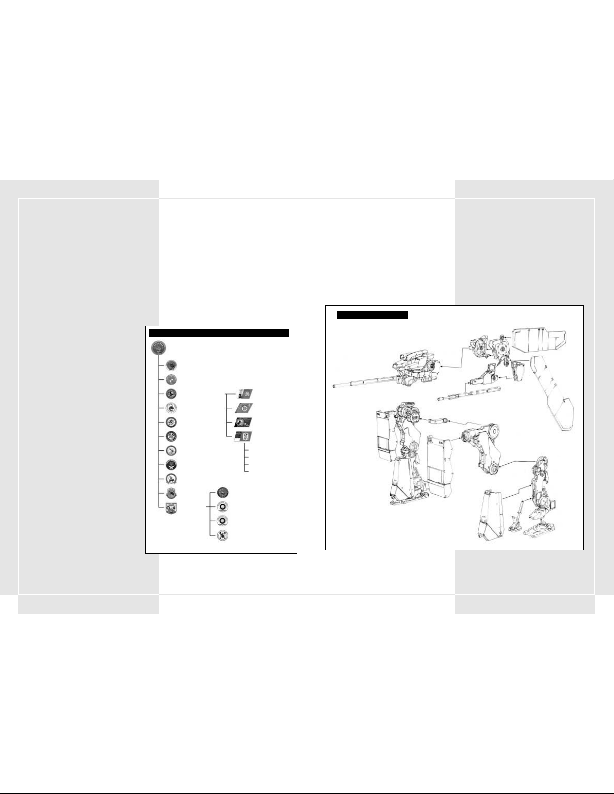
7776
2-1 VT-BASISTEILE
VTs bestehen hauptsächlich aus drei Haupteinheiten:
1. Rumpfeinheit
2. Beineinheit
3. Waffeneinheit
Manche Waffeneinheiten sind direkt an der Rumpfeinheit
montiert, während andere auch unabhängig davon funktionieren.
2-2 VT-BETRIEBSSYSTEM
Der Betrieb des VT wird über ein Betriebssystem mit Namen COOS
gesteuert. Es steuert den Stabilisator in der Beineinheit sowie das
Zielsystem der verschiedenen Waffen. Selbst bei identischen VTTypen setzen unterschiedliche geladene Betriebssysteme die
Kampfleistung der Typen beträchtlich herab. Das COOS, das durch
unzählige Experimente und im Kampfeinsatz erprobt wurde,
gehört zu den bestgehüteten militärischen Geheimnissen. Fahrer
müssen sich dessen bewusst sein. Wenn sie sich im Kampf
ausstoßen müssen, muss der VT zerstört werden, damit diese
Technologie nicht in die falschen Hände gelangt.
1-1 VT-KONZEPT
Der VT (Vertical Tank) ist noch ganz neu und kam erst in den letzten
acht Jahren als Waffe zum Einsatz. Aufgrund der enormen
Leistungsfähigkeit des VT sind viele Militärs dazu übergegangen, ihn
als Waffe einzusetzen.
Die Entwicklung militärischer Systeme stagniert. Im Zuge der
Abrüstung wurden viele militärische Projekte auf Eis gelegt und
unnötig große Armeen reduziert. Der VT mit seiner unglaublichen
Feuerkraft in Kombination mit der Möglichkeit, von einer Person
gelenkt zu werden, ersetzt bewaffnete Panzer und wird zweifellos
zur wichtigsten Waffe der meisten Streitkräfte werden.
1-2 GRUNDLAGEN FÜR DEN MILITÄRISCHEN
EINSATZ DES VT
Noch ist der VT heute nicht als militärische Standardwaffe im Einsatz.
Er wurde erst zweimal zu experimentellen Zwecken in lokalen
Konflikten eingesetzt. Der militärische Einsatz ist bis dato noch nicht
vollständig dokumentiert. Bevor das gesamte Potential des VT
genutzt werden kann, müssen alle Forschungsprojekte
abgeschlossen sein. Das militärische Potential erhöht sich je
nach Größe und Umfang zukünftiger Unruheherde. Der VT
wird hauptsächlich als leistungsstarke Waffe mit enormer
Feuerkraft zum Einsatz kommen und entwickelt bei
Kampfeinsätzen sein unschlagbares Potential, wenn er in
großer Stückzahl eingesetzt wird. In diesem Zusammenhang
muss jedoch erwähnt werden, dass der VT, verglichen mit
anderen Waffen oder Fahrzeugen, erst seit kurzem im Einsatz
ist. Um das militärische Potential des VT aufrechtzuerhalten,
sind Verstärkungstruppen absolut unerlässlich.
1-3 PFLICHTEN EINER
SPEZIALPANZEREINHEIT
Die Panzereinheit, die den VT als militärische Waffe einsetzt,
hat extrem wichtige Aufgaben zu erfüllen. In einem Kampf mit
mobiler Infanterie obliegt der Panzereinheit die Vernichtung
des Feindes, die Gefangennahme wichtiger Feinde, die
Übernahme verschiedener feindlicher Lager und die
Besetzung und Erhaltung feindlicher Gebiete. Der VT kommt
dabei hauptsächlich als mobiler Angreifer von Platoons zum
Einsatz, aber auch als einen Gegenangriff startende
Verteidigungseinheit. Da Zeit und Topografie bei VT-Einsätzen
keine Rolle spielen, dient er als wichtigste Waffe bei
Angriffen auf Gebiete mit problematischer Topografie. Der
Einsatz eines VT in Kombination mit mobilen Einheiten
(Panzern) erhöht die Feuerkraft der gesamten Truppe.
Manchmal wird der VT auch zusammen mit Luftstreitkräften
oder Seestreitkräften eingesetzt, um strategisch wichtige Orte
einzunehmen. Daneben dient er auch als strategische Waffe
bei Angriffen hinter feindlichen Linien.
1-4 ZUSAMMENSETZUNG EINER
SPEZIALPANZERDIVISION
Eine Panzerdivision besteht aus einem
Kommandoaußenposten, drei VT-Bataillonen, einem
Panzerbataillon, einem Artilleriebataillon, einem
Aufklärungsbataillon, einem technischen Bataillon, einem
Fernmeldebataillon, einem Luftabwehrbataillon, einem
Luftbataillon und einem Verstärkungsbataillon (siehe Tabelle
rechts). Die Verstärkungsdivision besteht aus einem
Nachschubbataillon, einem Waffenwartungsbataillon, einem
Transportbataillon und einem medizinischen Bataillon. Das
VT-Bataillon besteht aus vier VT-Kompanien. In jeder
Kompanie wiederum gibt es drei VT-Platoons und ein
Waffenunterstützungsplatoon (mit drei Maschinen pro
Platoon). Dem Waffenunterstützungsplatoon kommt nur eine
unterstützende Rolle zu, d. h. es greift nie von allein an.
1-5 VT PLATOON-EINSATZ
Ein VT-Platoon besteht aus 3 Fahrern, die die kleinen, mittleren und
schweren VT-Klassen lenken. Welcher VT-Typ gewählt wird, hängt
von der Art der zugeteilten Mission ab. Bevor eine Mission beginnt,
muss der Fahrer eine VT-Typenanfrage einreichen. Den VT-Transport
und die Verteilung von Ausrüstung für das VT-Platoon übernimmt das
VT-Ausrüstungsbataillon. Das Material wird bei den verschiedenen
Kompanien angeliefert, die es dann wiederum zu den
entsprechenden Verteilungspunkten transportieren. Es gibt drei VTMechaniker (einen leitenden Mechaniker und zwei weitere
Mechaniker), die jedem VT zugeordnet sind. Diesem Team übersteht,
je nach VT-Typ, ein Materialoffizier. Er hat die Kontrolle über die
gesamte Ausrüstung. VT-Platoons sind auf regelmäßige
Kompanietransporte angewiesen, um an ihr Gerät zu kommen, aber
in Krisensituationen verlassen sie sich auf die Nachschubbataillone
der Verstärkungsdivisionen. Auch das Waffenwartungsbataillon ist
für größere Aufgaben wie den Komplettaustausch von Teilen
zuständig.
ABSCHNITT 1. VT-KONZEPT UND SPEZIALPANZERDIVISION ABSCHNITT 2. VT-ZUSAMMENFASSUNG
7. SPEZIALPANZERDIVISION
32. Spezialpanzerbataillon
33. Spezialpanzerbataillon
34. Spezialpanzerbataillon
3. Spezialpanzerkompanie
4. Spezialpanzerkompanie
5. Spezialpanzerkompanie
6. Spezialpanzerkompanie
‡VT-Platoon
‡VT Platoon
‡VT Platoon
‡ Waffenunterstützungsplatoon
Nachschubbataillon
Transportbataillon
Medizinisches Bataillon
Waffenwartungsbataillon
80. Panzerbataillon
Aufklärungsbataillon
Technisches Bataillon
Luftabwehrbataillon
Fernmeldebataillon
Luftbataillon
Artilleriebataillon
Verstärkungstruppen
ZUSAMMENSETZUNG EINER SPEZIALPANZERDIVISION
VT-STRUKTURDIAGRAMM
Kugelgelenkbereich
(x-Achse)
x- und y-Achse
z-Achse
x-Achse
x-Achse
Diese Teile sind für Richtungsänderungen verantwortlich
Kugelgelenkbereich
Kugelgelenkbereich
Page 41
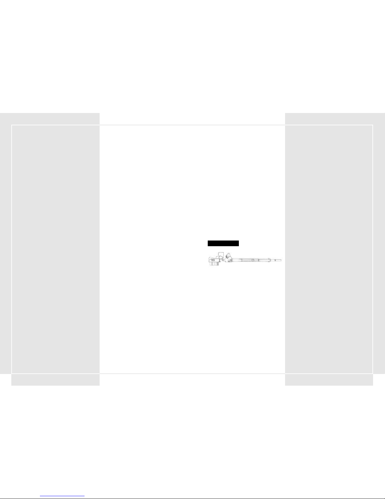
7978
2-10 WAFFENARSENAL DES VT
270 mm GEWEHR
Diese Waffe feuert panzerbrechende Munition mit leicht
gekrümmter Geschossflugbahn ab.
200 mm STURMGEWEHR
Obwohl die Reichweite dieses Gewehrs begrenzt ist,
besitzt sein automatisches Selbstladesystem die allerbesten
Schnellfeuereigenschaften.
270 mm STURMGEWEHR
Mit maximal fünf Schuss Schnellfeuermunition besitzt diese Waffe
genug Zerstörungskraft, um als wichtigste VT-Abwehrwaffe zu
dienen. Verglichen mit anderen Modellen dieser Generation ist
die Reichweite jedoch relativ gering.
315 mm DOPPELLAUFGEWEHR
Diese Waffe feuert gleichzeitig zwei panzerbrechende Geschosse
ab.
315 mm SCHNELLFEUERGEWEHR
Durch seine herausragende 3-Schuss-Feuerstoßfähigkeit bietet
diese Waffe mehr Schnellfeuerleistung als ein normales Gewehr.
355 mm SCHNELLFEUERGEWEHR
Durch seine herausragende 3-Schuss-Feuerstoßfähigkeit bietet
diese Waffe mehr Schnellfeuerleistung als ein normales Gewehr.
320 mm SCHARFSCHÜTZENGEWEHR
Diese Waffe ist für Ziele in großer Entfernung geeignet. Sie besitzt
eine größere Reichweite als ein normales Gewehr.
AK19-4A RÜCKSTOSSFREIES GEWEHR
Dieses Gewehr feuert hochexplosive Granaten ab. Es ist leicht,
und seine Feuerkraft ist praktisch mit der eines Gewehrs
vergleichbar. Aufgrund der langsamen Geschwindigkeit der
Geschosse ist es für den Feind relativ einfach, dem Feuerhagel zu
entgehen.
AK19-77 RÜCKSTOSSFREIES GEWEHR
Dieses Gewehr feuert hochexplosive Granaten mit
Kontaktzündern ab. Die Munition explodiert und richtet selbst
bei indirekten Treffern Schaden an.
315 mm FLINTE
Diese Waffe feuert APFSDS-Munition auf einer leicht gekrümmten
Geschossflugbahn ab. Sie besitzt eine größere Reichweite als ein
normales Gewehr.
2-3 VT-TYPEN
Die VTs werden nach Gewicht in Typen eingeteilt. Es gibt leichte,
mittelschwere und schwere Typen.
1. Leichte VTs
Bei diesem Modell liegt das Hauptaugenmerk auf der
Mobilität. Es wurde speziell für Einsätze entwickelt, bei
denen Sie hinter einem flüchtenden Feind herjagen oder
einen Angriff auf feindliche Basen wagen, deren Feuerkraft
größtenteils nicht mehr vorhanden ist. Leichte VTs können
auf dem Luftweg transportiert werden und wurden für das
Absetzen an speziellen strategisch wichtigen Orten
konzipiert. Sie können bei Luftangriffen auf Basen eine
elementare Rolle spielen.
2. Mittelschwere VTs
Der durchschnittliche mittelschwere VT-Typ dient als
wichtigste Feuerwaffe in der Spezialpanzerdivision. Zu den
Haupteigenschaften gehören seine Wendigkeit und schnellen
Bewegungen bei kontinuierlich starker Feuerkraft und
starker Panzerung. Von diesem Typus gibt es die meisten
Modelle. Dieser VT bietet durch seine Bestückbarkeit mit
Panzerungen und Waffen die vielfältigsten
Einsatzmöglichkeiten.
3. Schwere VTs
VTs mit schwerer Panzerung und großer Feuerkraft. Sie sind
unbeweglicher als leichte oder mittelschwere VTs. Wegen
ihrer enormen Feuerkraft und Panzerung werden diese VTs
hauptsächlich zum Schutz von strategisch wichtigen Orten
und Basen eingesetzt.
2-4 BEWEGUNG
Die durchschnittliche Geschwindigkeit dieses mittelschweren VT
beträgt 100 Kilometer pro Stunde. VTs dieser Art können vom
Hangar aus eine Entfernung von 205 Kilometer zurücklegen. Diese
Basiswerte variieren in Abhängigkeit von der Wartung der Teile,
der Topografie und den Fähigkeiten des Fahrers.
Der Stabilisator, der die Stabilität der Beineinheit steuert, hat
Einfluss auf die Bewegungen des VT. Diese Fähigkeit wird in
Punkten angegeben. Je höher die Punktzahl des Stabilisators,
desto stabiler der VT.
2-5 KRAFTSTOFFTANK UND ERSATZTANKS
An der Rumpfeinheit ist ein fest montierter Kraftstofftank
angebracht. Das Fassungsvermögen des Tanks ist abhängig von
der Art des Tanks. Der M-7 Decider VT (wichtigster Panzer für die
Pacific Rim Forces) besitzt ein Fassungsvermögen von 6000
Gallonen Kraftstoff, die für einen fünfminütigen Einsatz pro Tank
reichen.
Manche VTs besitzten Ersatztanks, die einen längeren Einsatz
ermöglichen. Die Anzahl von Ersatztanks eines VT hängt vom VTTyp ab. Im Durchschnitt besitzt ein VT nur einen oder zwei
Ersatztanks.
Ein Ersatztank besitzt ein Fassungsvermögen von 6000 Gallonen.
Durch Drücken der Tank Detach-Taste auf der Hauptkonsole
können Sie Ersatzkraftstofftanks entfernen. Ihr VT wird dadurch
schneller und mobiler. Ist einer Ihrer Ersatztanks leer, sollten Sie
ihn schnell loswerden.
2-6 KRAFTSTOFFVERBRAUCH UND
GESCHÄTZTE EINSATZDAUER
Sie können im Kampf verwendeten Kraftstoff nach Einreichung
einer Nachschubanforderung nachtanken. Wenn Sie sich in einer
Situation befinden, in der Sie nicht nachtanken können und
Ihnen bald der Kraftstoff ausgeht, könnte es sein, dass Sie Ihren
VT zurücklassen müssen.
Um solche Situationen zu vermeiden, können Sie dem
Einsatzprotokoll, das dem Kampf vorausgeht, die geschätzte
Einsatzdauer entnehmen. Überlegen Sie sich, wie viele
Bewegungen Sie im Kampf ausführen müssen und entscheiden Sie
dann, wie viele Ersatzkraftstofftanks Sie benötigen.
Der für den Kraftstoffverbrauch des VT günstigste Gang ist der
dritte Gang. In diesem Gang lassen sich die Standardbewegungen
und die Geschwindigkeiten des patrouillierenden VT am Besten
steuern. Sie können aber auch die Einsatzdauer Ihres VT
verlängern, indem Sie die Anzahl von Gleitschritten und anderen
Bewegungen, die viel Kraftstoff schlucken, reduzieren.
2-7 SCHUTZPANZERUNG
Die Verteidigungskraft des VT wird auch als „Panzerungsgrad“
bezeichnet. Ein Anzeiger auf der Bedientafel gibt vier
verschiedene Panzerungsgrade an. Jedes Mal, wenn ein VT
getroffen und beschädigt wurde, zeigt der Anzeiger einen
niedrigeren Wert an. Mit abnehmendem Wert ist der Fahrer in
Gefahr. Sinkt der Wert in einen gefährlich niedrigen Bereich ab,
erhält der Fahrer eine Warnmeldung. Sie sollten sich jetzt aus
dem Kampf zurückziehen oder sich so bald wie möglich aus dem
Cockpit ausstoßen. (Näheres dazu finden Sie in den Abschnitten
4-19 bis 4-21). Sie können, abhängig vom Typ Ihres VT, die
Panzerung Ihres VT verstärken.
2-8 HAUPTWAFFEN UND UNTERWAFFEN
VT-Waffen werden in Haupt- und Nebenkategorien eingeteilt.
Diese unterscheiden sich von den Standardwaffen. Die
Hauptwaffen sind normalerweise auf der Waffeneinheit des VT
montiert, während die Unterwaffen irgendwo anders angebracht
sind. Sie können den Waffentyp abhängig davon, wo die Waffe
befestigt ist, festlegen. Waffen werden nicht nach Stärke
eingeteilt.
2-9 MAXIMAL ZULÄSSIGES WAFFENGEWICHT
VT-Waffen sollten nur als Option betrachtet werden. Manche
Waffen sind für jeden VT-Typ geeignet, andere wiederum
unterscheiden sich dadurch voneinander, dass sie nur an einem
bestimmten VT angebracht sind. Sie können sich drei
Unterwaffen- und drei Hauptwaffentypen aussuchen. Das
zulässige Waffengewicht hängt vom Typ des VT ab. Das maximal
zulässige Waffengewicht (Gesamtgewicht der Waffen, die ein VT
mit sich führen darf) wird angezeigt, um Ihnen die Auswahl zu
erleichtern.
270 mm GEWEHR
Page 42

8180
SQUALL – GELENKTER
PANZERABWEHRMÖRSER
Hierbei handelt es such um die einzige VT-Abwehrwaffe mit
Zielverfolgung, die ihre Geschosse im hohen Bogen abfeuern
kann.
SCHIENENKANONE A
Das hier ist die neueste von PRF entwickelte Waffe. Durch
elektromagnetische Beschleunigung feuert diese Waffe Projektile
mit extrem hohen Geschwindigkeiten ab. Sie besitzt beispiellose
Reichweite und Feuerkraft.
SCHIENENKANONE B
Eine auf Hai Shi Dao entwickelte Schienenkanone. Durch
elektromagnetische Beschleunigung feuert diese Waffe Projektile
mit extrem hohen Geschwindigkeiten ab. Sie besitzt beispiellose
Reichweite und Feuerkraft.
HVM-RAKETENWERFER
Diese Waffe feuert strahlgetriebene, panzerbrechende Munition
ab. Obwohl Reichweite und Feuerkraft dieser Waffe zur Besten
ihrer Klasse gehören, besitzt sie kein Zielflugsystem.
225 mm HAUBITZE
Diese Waffe feuert Granaten mit stark gekrümmten
Geschossflugbahnen ab. Obwohl die Waffe nicht allzu viel
Zerstörung anrichtet, verursachen die Geschosse beim Aufprall
dennoch Schäden in einem begrenzten Radius. In Gebieten mit
einer großen Dichte an gepanzerten Fahrzeugen ist sie sehr
wirksam.
305 mm HAUBITZE
Diese Waffe feuert Granaten mit stark gekrümmten
Geschossflugbahnen ab. Obwohl die Waffe nicht allzu viel
Zerstörung anrichtet, verursachen die Geschosse beim Aufprall
dennoch Schäden in einem begrenzten Radius. In Gebieten mit
einer großen Dichte an gepanzerten Fahrzeugen ist sie sehr
wirksam.
370 mm HAUBITZE
Diese Waffe feuert Granaten mit stark gekrümmten
Geschossflugbahnen ab. Sie richtet beim Einschlag Schäden in
einem festgelegten Radius an. Je nach Einsatzbereich ist sie sehr
wirksam.
550 mm HAUBITZE
Diese Waffe feuert Granaten mit stark gekrümmten
Geschossflugbahnen ab. Sie ist sehr zerstörerisch und kann
enorme Schäden in einem festgelegten Radius anrichten.
8-SCHUSS ARTILLERIERAKETENSYSTEM MLRS
Dieses 8-Schuss-Artillerieraketensystem schießt große Raketen
mit stark gekrümmten Geschossflugbahnen ab. Es richtet mit
seinem beträchtlichen Wirkungsradius große Schäden an. Diese
Waffe ist besonders dann sehr effizient, wenn es darum geht, ein
großes Stück Land zu erobern.
355 mm FLINTE
Diese Waffe feuert APFSDS-Munition auf einer leicht gekrümmten
Geschossflugbahn ab. Sie besitzt eine größere Reichweite als ein
normales Gewehr.
430 mm FLINTE
Diese Waffe ist die größte ihrer Art. Ihre Zerstörungskraft und
Reichweite sind überaus zufriedenstellend.
67 mm KETTENGEWEHR
Diese Waffe hat Schnellfeuereigenschaften und feuert kleine
panzerbrechende Munition ab. Da die Feuerkraft relativ gering
ist, eignet sich diese Waffe nicht für einen Einsatz gegen VTs. Als
Waffe gegen gepanzerte Fahrzeuge und Kampfhubschrauber ist
sie jedoch bestens geeignet.
80 mm KETTENGEWEHR
Diese Waffe hat Schnellfeuereigenschaften und feuert kleine
panzerbrechende Munition ab. Da die Feuerkraft relativ gering
ist, eignet sich diese Waffe nicht für einen Einsatz gegen VTs. Als
Waffe gegen gepanzerte Fahrzeuge und Kampfhubschrauber ist
sie jedoch bestens geeignet.
100 mm KETTENGEWEHR
Diese Waffe hat Schnellfeuereigenschaften und feuert kleine
panzerbrechende Munition ab. Da die Feuerkraft relativ gering
ist, eignet sich diese Waffe nicht für einen Einsatz gegen VTs. Als
Waffe gegen gepanzerte Fahrzeuge und Kampfhubschrauber ist
sie jedoch bestens geeignet.
120 mm SCHWERES MASCHINENGEWEHR
Diese Waffe ist noch zerstörerischer als das Kettengewehr.
Obwohl sie schnellfeuerfähig ist, ist sie nicht so effizient wie eine
VT-Abwehrwaffe. Im Kampf gegen mobile
Unterstützungsgeschütze ist sie jedoch bestens geeignet.
140 mm SCHWERES MASCHINENGEWEHR
Diese Waffe ist noch zerstörerischer als das Kettengewehr.
Obwohl es schnellfeuerfähig ist, ist es nicht so effizient wie eine
VT-Abwehrwaffe. Im Kampf gegen mobile
Unterstützungsgeschütze ist es jedoch bestens geeignet.
135 mm PITO - SCHWERES MASCHINENGEWEHR
Dieses schwere Maschinengewehr passt unter jede VTRumpfeinheit. Es ist leistungsfähiger als ein Kettengewehr und ist
durch seine Schnellfeuereigenschaften als Sekundärarsenal
hervorragend geeignet.
MK21 ANTI-BODEN-RAKETENGESCHÜTZ
Diese Waffe kann sechs mittelgroße Antibodenraketen
gleichzeitig abfeuern.
MK34 ANTI-BODEN-RAKETENGESCHÜTZ
Diese Waffe kann vier mittelgroße Antibodenraketen gleichzeitig
abfeuern und stellt für jeden VT eine lebensgefährliche
Bedrohung dar.
SCHIENENKANONE
370 mm HAUBITZE
67 mm KETTENGEWEHR
120 mm MASCHINENGESCHÜTZ
MK21 ANTI-BODEN-RAKETENGESCHÜTZ
Page 43

8382
FLAMMENWERFER
Diese Waffe ist für den Nahkampf gedacht und lässt sich unter der
Rumpfeinheit des VT anbringen. Wird ein VT direkt von dieser
Waffe getroffen, explodiert er und geht in Flammen auf.
STUN ROD
Diese Waffe, die speziell für den Nahkampf mit einem VT
entwickelt wurde, setzt mit ihren starken Stromstößen den VT
vorübergehend außer Gefecht.
ABRISSAUSLEGER
Dieser große Abrissausleger wird nachträglich für
Nahkampfzwecke am VT angebracht. Dabei handelt es sich um die
zerstörerischste Nahkampfwaffe.
ZEITGEZÜNDETE GRANATE
Diese Granate wurde hauptsächlich für Nahkampfeinsätze
konzipiert. Wegen ihres Kontaktzünders im Inneren detoniert die
Granate und richtet sogar dann großen Schaden an, wenn das Ziel
gar nicht direkt getroffen wurde.
ZEITGEZÜNDETE GRANATE, KAPAZITÄT DREI
SCHUSS
Diese Granate wurde hauptsächlich für Nahkampfeinsätze
konzipiert. Wegen ihres Kontaktzünders im Inneren detoniert die
Granate und richtet sogar dann großen Schaden an, wenn das Ziel
gar nicht direkt getroffen wurde.
NEBELWERFER
Diese Waffe feuert vier Schuss Nebelgranaten ab. Einziges Ziel
dabei ist, so dichten Nebel zu bilden, dass die schlechte Sicht des
Feindes einen Angriff verhindert.
PANZERABWEHR-MINENWERFER
Diese Waffe kann drei Panzerabwehrminen gleichzeitig
abschießen.
TREIBSTOFFTANK
Hierbei handelt es sich um einen Kraftstofftank für den VT. Ist er
leer, lässt er sich entfernen, um Ihr Gewicht zu reduzieren.
ZUSÄTZLICHE PANZERUNG
Zusätzliche Panzerung erhöht die Lebensdauer des VT. Außerdem
kann der Fahrer dadurch im Waffenbehälter mitgeführte
Lenkraketen einsetzen. Drücken Sie im Kampfeinsatz F1, um sie
abzuschießen.
ERSATZNACHSCHUB
Zum Ersatznachschub gehören Munition und Kraftstoff. Eine
Fuhre Ersatznachschub wird auf Anfrage von einem
Versorgungshubschrauber angeliefert.
BOOM BOX
Dieser antike Kassettenrekorder wurde im Lager der
Trainingseinrichtung entdeckt. Hängen Sie ihn sich in das
Cockpit, um sich während des Kampfes ein paar Lieder
anzuhören.
12-SCHUSS ARTILLERIERAKETENSYSTEM MLRS
Dieses 12-Schuss-Artillerieraketensystem schießt große Raketen
mit stark gekrümmten Geschlossflugbahnen ab. Es richtet mit
seinem beträchtlichen Wirkungsradius große Schäden an. Diese
Waffe ist besonders dann sehr effizient, wenn es darum geht, ein
großes Stück Land zu erobern.
KOMPAKTER DOPPELRAKETENWERFER
Hierbei handelt es sich um einen kompakten
Doppelraketenwerfer, der unter die Rumpfeinheit des VT passt.
KOMPAKTER DREIFACH-RAKETENWERFER
Hierbei handelt es sich um einen kompakten DreifachRaketenwerfer, der unter die Rumpfeinheit des VT passt.
ASLAM (Advanced Stand-Off Land Attack Missile)
GELENKTE PANZERABWEHRRAKETE
Eine infrarotgesteuerte Rakete, die keine Gnade kennt. Je
nachdem, wie die Bewegungsmuster des VT programmiert sind,
verbessert sich die Zielgenauigkeit, d. h. die Anzahl an direkten
Treffern ist extrem hoch.
POZIT – GELENKTE PANZERABWEHRRAKETE
Eine infrarotgesteuerte Rakete, die keine Gnade kennt. Obwohl
diese Rakete im Vergleich zu den ASLAM-Varianten unterlegen ist,
wirkt diese Waffe dennoch punktgenau und zerstörerisch.
KOMPAKTE DOPPELLENKRAKETE
Hierbei handelt es sich um einen kompakten
Doppelraketenwerfer, der unter die Rumpfeinheit des VT passt.
Trotz der geringen Leistungsfähigkeit dieser Waffe ist diese mit
einem Zielerfassungssystem ausgerüstet.
AVTDV-LENKRAKETE
Hierbei handelt es sich um eine große Panzerabwehrrakete, die
auch als „VT-Killer“ bezeichnet wird. Diese Rakete ist wegen ihres
ausgeklügelten Lenksystems, ihrer erheblichen Schussweite und
ihrer zerstörerischen Wirkung die tödlichste von allen.
AL C205 PLASMAWERFER
Diese Waffe, die speziell für den Nahkampf mit VTs entwickelt
wurde, ist sehr zerstörerisch und hat den Vorteil, dass sie einen
Feind durch einen direkten Treffer auslöschen kann.
AL C22B PLASMAWERFER
Diese Waffe, die speziell für den Nahkampf mit VTs entwickelt
wurde, ist sehr zerstörerisch und hat den Vorteil, dass sie einen
Feind durch einen direkten Treffer auslöschen kann.
NAPALM
Napalmgeschosse lassen sich in jeden kompakten Raketenwerfer
integrieren, der unter die VT-Rumpfeinheit passt. Napalm ist für
den Einsatz gegen feindliche Bodentruppen sehr gut geeignet,
weil es ein festgelegtes Gebiet im Handumdrehen in Flammen
aufgehen lassen kann. Bekommt ein VT einen direkten
Napalmtreffer ab, geht er sofort in Flammen auf.
AL C205 PLASMAWERFER
GELENKTE PANZERABWEHRRAKETE
ZEITGEZÜNDETE GRANATE
Page 44
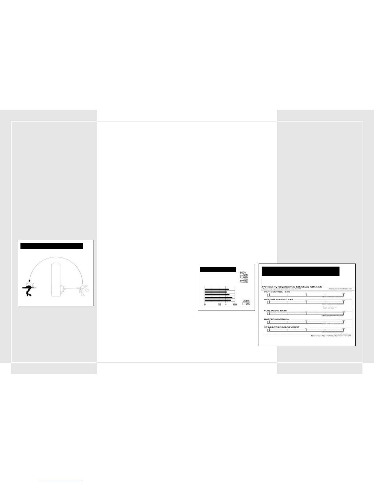
8584
2-11 ZIELAUSRICHTUNG VON WAFFEN MIT
GEKRÜMMTEN GESCHOSSFLUGBAHNEN AUF DER
KRIEGSKARTE
Sie sollten Ihr Ziel erst anpeilen, wenn Sie eine Waffe mit
gekrümmten Geschossflugbahnen einsetzen. Wenn Sie sich für eine
Waffe mit gekrümmter Geschossflugbahn entschieden haben,
werden Ziel, Schussrichtung und Auftreffpunkt des Geschosses als
weiße Linie auf der Kriegskarte dargestellt. Sie können diese
Informationen nutzen, um den Feind selbst dann zu treffen, wenn Sie
ihn nicht anvisiert haben.
2-12 KURZZÜNDER
Bei der Munition für rückschlagfreie Ak19-77-Geschütze und bei
Kurzstreckengranaten wurde ein Kurzzünder integriert
(normalerweise wird bei der konventionellen Artillerie ein
Kontaktzünder eingesetzt). Kurzzünder machen sich den
Magnetismus zunutze, um das Ziel zu finden, und explodieren, sobald
sie eine voreingestellte Entfernung erreicht haben. Dadurch erübrigt
sich ein direkter Treffer, um das Ziel zu zerstören. Im
Kampfgeschehen, an dem schnelle, mobile VTs beteiligt sind, spielen
diese Kurzzünder eine wichtige Rolle wenn es darum geht, den
Gegner außer Gefecht zu setzen.
2-13 VERTEIDIGUNG MITHILFE VON DÜPPELN
Um ein Radar vor feindlichen Raketen zu schützen, wurde derVT mit
einem sogenannten Düppel versehen. Die Düppel explodieren in vier
verschiedene Richtungen, nachdem der VT mit einer Rakete
beschossen wurde. Aluminiumstreifen explodieren in der Luft, die
Lenkrakete nimmt Kurs auf die Düppel und wird so abgelenkt, dass
sie ihr eigentliches Ziel verfehlt.
Wenn Sie nach der Aktivierung der Düppel einen Schritt zur Seite
machen, können Sie der Rakete noch besser ausweichen.
GEKRÜMMTE GESCHOSSFLUGBAHNEN IM VERGLEICH ZU
LINEAREN GESCHOSSFLUGBAHNEN
Gekrümmte Geschossflugbahn
Lineare Geschossflugbahn
3-1 ZUSÄTZE FÜR COOS DER 2. GENERATION
Vor kurzem wurde COOS, das alle Bewegungen des VT lenkt, zu
einem System der 2. Generation aufgerüstet. Dies hat zu einer
Verbesserung der Funktionalitäten des VT geführt. Zusätzlich zu
der erhöhten Prozessorleistung steuert COOS jetzt auch
neue Panzerabwehr-Lenkwaffen und ein zielabschätzendes
Feuersystem FSS. Diese neuen Zusatzfähigkeiten verleihen dem
VT noch mehr zerstörerische Kraft. Weiter unten finden Sie eine
Aufstellung vieler Funktionen des COOS der 2. Generation.
3-2 FSS-FUNKTION (Zielabschätzendes
Feuersystem)
Das FSS analysiert die Bewegungsmuster des VT, die Entfernung,
die das Geschoss zurücklegt und wie lange es in der Luft sein
wird. Danach wird der Zielsucher automatisch auf den nächsten
wahrscheinlichen Aufenthaltsort des Feindes ausgerichtet. Durch
Drücken der FSS-Taste kann der FSS-Zielmodus in den normalen
„Linearmodus“ umgeschaltet werden. Nähere Informationen zum
FSS-System können Sie Abschnitt 5-4 entnehmen.
3-3 OVERDRIVE-FUNKTION
Diese Funktion dient dazu, dem VT für eine begrenzte Dauer eine
erhöhte Geschwindigkeit zu verleihen. Sie deaktiviert den
Drehzahlbegrenzer, der die verschiedenen Gelenke vor
Verschleiß schützt. Weitere Informationen zur OverdriveFunktion können Sie Abschnitt 4-6 entnehmen.
3-4 TARNFUNKTION
Die in den VT integrierte Tarnfunktion verhindert die Erkennung
durch Radar. Erreicht wird dies durch einen Radarstrahlen
reflektierenden Anstrich, verbesserte Leitungen für die
Gasentweichung und eine dynamischere Ausgestaltung des
Rumpfes.
3-5 LENKWAFFEN
Zu den größten Errungenschaften des COOS der 2. Generation
gehört der verbesserte Einsatz von Lenkwaffen. Integriert
wurden zusätzlich zum bereits existierenden Laser Active
Guidance System (Laser-Lenksystem) neue Lenkraketen zur
Panzerabwehr. Dieses System analysiert die Bewegungsmuster
des VT und berechnet den nächsten Aufenthaltsort des Feindes
unter Zuhilfenahme des FSS-Systems in Echtzeit. Dies erhöht die
Treffergenauigkeit. Es wird damit gerechnet, dass sich das neue
System bei der Panzerabwehr als äußerst effizient herausstellt.
ABSCHNITT 3.
SONDERFUNKTIONEN DURCH
COOS DER 2. GENERATION
4-1 STARTSEQUENZ
Wenn Sie zum ersten Mal in einen VT steigen, um in den Kampf zu
ziehen, ist die Batterie voll aufgeladen und der Kraftstofftank gefüllt.
Außerdem sind alle Waffen voll einsatzbereit. Die VT-Startsequenz ist
unten aufgeführt.
1. Schließen Sie die Cockpitluke
Drücken Sie die Cockpit Hatch-Taste (Cockpitlukentaste) auf
der rechten Seite. Überprüfen Sie, ob die Cockpitluke geöffnet
oder geschlossen ist.
2. Drücken Sie die Ignition-Taste (Zündtaste).
Drücken Sie die Ignition-Taste (Zündtaste) direkt unter der
Cockpit Hatch-Taste (Cockpitlukentaste). Der Motor startet.
Der Generator erzeugt nun Energie, die das Cockpit mit Strom
versorgt. Das Betriebssystem des VT wird aktiviert und ein
einfacher Funktionscheck wird automatisch auf dem Bildschirm
angezeigt, bevor der Startbildschirm mit allen Funktionen
erscheint.
3. Startfunktionen
Nachdem der Funktionscheck angezeigt wurde, müssen Sie jede
einzelne der folgenden Funktionen aktivieren und dabei
prüfen, ob sie funktionstüchtig ist. Gehen Sie die Funktionen
der Reihe nach durch, indem Sie sie mit dem Zeigefinger
aktivieren.
•Oxygen Supply System (OSS) (Sauerstoffversorgungssystem)
– Versorgt den Innenraum des Cockpits mit Sauerstoff zum
Atmen.
• Filter Control System (FCS) (Filtersteuerungssystem) –
Kipphebelschalter, der das System für die Ableitung heißer
Gase steuert. Leitet das heiße Gas ab und stabilisiert den
Motor.
• VT-Location Measurement (VT-Orientierungssystem) –
Einheiten-Lokalisierungssystem. Eine Funktion zur
automatischen Darstellung Ihres VT auf der Kriegskarte.
• Buffer Material (Puffermaterial) – Ein System, das ein
Schutzmaterial um das Cockpit herum absondert, um es vor
Angriffen zu schützen. Es ummantelt das Cockpit und den
Brustbereich des VT mit einem schützenden Hartgel.
• Fuel Flow Rate (Kraftstoffdurchlassrate) – Ein System, das
den Kraftstoffdurchlass reguliert. Es steuert den
Kraftstoffdurchlass und zerstäubt die richtige Menge
Kraftstoff je nach aktuellem Motorzustand.
4. Drücken Sie die Start-Taste
Sobald Sie die Startsequenz initiiert haben, erscheint ein Bild
der äußeren Umgebung. Danach gelangt über ein Stellglied
Energie in die verschiedenen Gelenke des VT. Sobald die
verschiedenen Systeme stabil laufen, drücken Sie die Start-
Taste. Nachdem Sie die verschiedenen Funktionen beendet
haben, müsste ihr VT in den Startmodus umschalten, damit Sie
ihn lenken können.
4-2 ANHALTEN DES VT WÄHREND DES STARTS
Das Drücken der Start-Taste vor dem Übergang der Systeme in den
stabilen Betrieb hat zur Folge, dass mehrere Gelenkteile nicht
einrasten. Brechen Sie die Startsequenz ab und halten Sie den VT an.
Dies schützt den VT vor Schäden durch Überbeanspruchung. Wenn
Sie den VT während des Starts anhalten, entspannen Sie sich und
warten Sie, bis die verschiedenen Systeme wieder hochgefahren
wurden. Danach können Sie versuchen, Ihren VT neu zu starten,
indem Sie die Start-Taste drücken.
ABSCHNITT 4. VT-STEUERUNGEN
Stabilization Line
(Stabilisationslinie)
PRIMARY SYSTEMS STATUS CHECK (PRIMÄRER
SYSTEMSTATUSCHECK)
START-BILDSCHIRM
Page 45

8786
BASISSTEUERUNGEN
4-3 BEWEGEN UND ANHALTEN
Bewegen und Anhalten gehören zu den beiden wichtigsten
Grundbewegungen des VT. Wenn Sie auf das Gaspedal drücken,
erhöht sich die Umdrehungszahl des Motors und der VT bewegt
sich vorwärts. Sie können den Schalthebel auch in den
Rückwärtsgang legen, um rückwärts zu gehen. Sie halten den VT
an, indem Sie Ihren Fuß vom Gaspedal nehmen und das
Bremspedal drücken. Wenn Sie mit zu hoher Geschwindigkeit in
steile Kurven gehen, könnte es sein, dass Ihr VT umkippt, also
Vorsicht!
4-4 BESCHLEUNIGEN UND BREMSEN
Wie stark Sie beschleunigen oder bremsen hängt davon ab, wie
fest Sie das Gaspedal drücken. Das Bremsen erfolgt durch
Drücken des Bremspedals oder durch Herunterschalten in einen
niedrigeren Gang. Im Leerlauf erreicht Ihr VT 0 km/Std. Je höher
Sie schalten, desto schneller können Sie fahren, aber desto
weniger Drehmoment wird erzeugt. Dort, wo die Geschwindigkeit
nicht gleichmäßig zunimmt, empfiehlt es sich herunterzuschalten,
um Kraftstoff zu sparen. Wenn Sie den Schalthebel in den
Rückwärtsgang schalten, bewegt sich der VT rückwärts.
4-5 DREHUNG
Die Drehung des VT erfolgt durch Drücken des linken
Drehhebels
oder . Die Drehgeschwindigkeit nimmt in
Abhängigkeit vom Druck, der auf den Drehstick gleich in welche
Richtung ausgeübt wird, zu. Kann der Stabilisator das
Gleichgewicht des VT nicht halten, kippt der VT um, also Vorsicht.
4-6 OVERDRIVE
Diese Funktion wurde auf Anfrage vieler talentierter Fahrer
entwickelt. Sie deaktiviert den Drehzahlbegrenzer, der die
verschiedenen Gelenke vor Verschleiß schützt und eine
Verlangsamung zur Folge hat. Dieser Begrenzer wird deaktiviert,
sobald Sie die Overdrive-Taste drücken. Ausgeschaltet wird die
Deaktivierung durch erneutes Drücken der Overdrive-Taste.
Befindet sich der VT im Overdrive-Modus, verbraucht er im
Gegensatz zum Normalbetrieb drei Mal so viel Kraftstoff, also
gehen Sie mit dieser Funktion sorgsam um.
4-7 GLEITSCHRITTFUNKTION
Hierbei handelt es sich um eine für den VT typische Art,
Feuersalven auszuweichen. Zwischen einem VT und einem
gewöhnlichen Panzer besteht ein großer Unterschied. Sie können
mithilfe des Betriebssystems blitzschnell nach rechts oder links
ausweichen. Sie können diese Funktion aber auch dazu nutzen,
das Gleichgewicht wiederzufinden, wenn Ihr VT kurz davor ist
umzukippen. Der Gleitschritt ist eine schnelle Bewegung in eine
von vier Richtungen unter Verwendung von vorprogrammierten
Pfaden. Ausgeführt wird er als Kombination aus Beschleunigung
und Stabilisatoreinsatz. Der Stabilisator verstärkt die
Gelenke/Bereiche, die am meisten von Verschleiß betroffen sind.
Der Gleitschritt wird ausgeführt, wenn Sie gleichzeitig den
Rotation Lever (Drehhebel)
oder drücken und dabei das
Gleitschrittpedal gedrückt halten. Der Gleitschritt ist
hervorragend geeignet, um feindlichen Angriffen auszuweichen.
Eine andere Bewegung kann ausgeführt werden, wenn Sie den
Rotation Lever (Drehhebel) im Leerlauf lassen und das
Gleitschrittpedal drücken. Dadurch macht Ihr VT einen Satz nach
vorne. Befindet sich der Drehhebel in Rückwärtsstellung, macht
der VT einen Satz nach hinten.
4-8 GLEITSCHRITTFUNKTIONSEINSCHRÄNKUNGEN
Ein Gleitschritt stellt eine große Belastung für die Gelenkbereiche
des VT dar. Um Verschleiß zu reduzieren, wird über das Stellglied
eine große Menge Energie verbraucht. Energie aus dem Generator
wird in die Hauptbatterie zurück gespeist. Ein Gleitschritt setzt
jedoch die Batterieleistung erheblich herab. Wenn nicht mehr
genug Leistung zur Verfügung steht, wird der Gleitschritt
automatisch deaktiviert. Ist die Batterieleistung niedrig, leuchtet
ein Überhitzungswarnlicht auf. Leuchtet dieses Warnlicht auf,
darf kein Gleitschritt ausgeführt werden.
4-9 GLEITSCHRITT-KIPPSTABILISATOR
Immer wenn die Bewegung des VT die Grenzen des Stabilisators
überschreitet, besteht die Gefahr, dass der VT nach vorne
überkippt. Ein Überkippen erfolgt bei rücksichtslosen Einsätzen
oder schnellen Drehungen bei hoher Geschwindigkeit. Es kann
aber auch dann vorkommen, wenn Sie vom Feind getroffen
wurden. Wenn die Gefahr des Umkippens besteht, drücken Sie
das Gleitschrittpedal, um den VT ins Gleichgewicht zu bringen.
Ist die Batterieleistung des VT schwach, ist dieses Manöver
blockiert. Sollte es doch mal vorkommen, dass Sie umkippen,
lassen Sie das Gaspedal los und drücken Sie es erneut, um Ihren
VT wieder in eine aufrechte Position zu bringen.
4-10 ABSCHALTFUNKTION
In Fällen, in denen Sie so schwer getroffen wurden, dass Ihre
Schadenskapazitätsgrenze erreicht wurde, fährt Ihr VT den
Betrieb automatisch herunter, um die diversen Gelenkbereiche
vor weiteren Schäden zu schützen. Tritt dieser Fall ein, werden
alle Sperren entriegelt, und der VT kommt zum Stehen. Sie
müssen dann schnell die Startsequenz durchlaufen, um den VT
wieder hochzufahren.
GLEITSCHRITTFUNKTION
4-11 MANIPULATOR-STEUERUNGEN
Ein Manipulator im VT steuert einen Arm, der Türen öffnen und
schließen und Fracht bewegen kann. Er ist links vom Rumpf
angebracht. Drücken Sie die Manipulator-Taste, um ihn
einzuschalten. Wenn Sie den Manipulator auf ein Ziel ausrichten
und dann die Sub-Weapon-Taste (Unterwaffentaste) drücken,
können Sie den Gegenstand aufheben. Da Sie die Sub Weapon-
Taste (Unterwaffentaste) drücken müssen, um den Manipulator
zu bedienen, können Sie in dieser Zeit keine Unterwaffen
einsetzen.
EINSATZ DES MANIPULATORS ZUR
STEUERUNG EINES LIFTS
VERWENDUNG DES MANIPULATORS ZUM ÖFFNEN
UND SCHLIESSEN VON FRACHTTÜREN
MANIPULATOR
Normales Zielen mit Unterwaffen
Zielen im Manipulator-Modus
EINSAMMELN VON GEGENSTÄNDEN MITHILFE
DES MANIPULATORS
Page 46

8988
VT-MONITOR
4-12 HAUPTKAMERAWECHSEL
Der Blickwinkel des VT wird von der Hauptkamera bestimmt.
Dieses Bild wird ins Cockpit übertragen. Die Kamera ist
normalerweise mittig nach vorne gerichtet. Durch Drücken des
Knopfes auf dem linken Fahrerstick
,
, oder können
Sie das Sichtfeld vergrößern. Durch Drücken des Control Stick-
Knopfes können Sie die Ansicht direkt auf die Mitte des VT
zentrieren. Damit und mithilfe des VT-Sub-Monitors (wird später
beschrieben) können Sie Ihren VT bewegen und seine
Einsatzfähigkeit im Kampf verbessern.
4-13 HAUPTKAMERA SCHMUTZ UND STAUB
Bei Kampfeinsätzen müssen Sie eine klare Sicht auf dem
Hauptschirm haben. Für den Fall, dass der Bildschirm durch
Schmutz und Staub Grau wird, drücken Sie die Washing-Taste
(Waschtaste), um ihn zu säubern.
KAMERAPERSPEKTIVEN
4-14 SUB-MONITOR-FUNKTIONEN
Durch Drücken der Sub-Monitor-Auswahltaste unter dem
Hauptmonitor können Sie zwischen vier Modi wählen.
• Front View Mode (Modus Frontansicht)
Zeigt an, was sich direkt vor dem VT abspielt. Nutzen Sie
diese Ansicht zusammen mit der
Schauplatzänderungsfunktion, um sich die Geschehnisse
genauer anzusehen.
•Back View Mode (Modus Rückansicht)
Zeigt an, was sich direkt hinter dem VT abspielt. Wie bei der
Frontansicht, kann auch diese Ansicht zusammen mit der
Schauplatzänderungsfunktion genutzt werden, um sich die
Geschehnisse genauer anzusehen.
•Modus Zielerfassungsansicht
Zum Heranzoomen des erfassten Zieles. Ein sehr weit
entferntes Ziel wird immer auf dem Sub-Monitor dargestellt,
ohne dass es herangezoomt wird.
• Modus Vogelperspektive
In dieser Ansicht wird der VT aus einer Höhe von 50 Metern
angezeigt. Diese Ansicht ist sehr nützlich für die Erkundung
toter Winkel und die genauere Begutachtung der Umgebung
von Objekten.
4-15 NACHTSICHTAUSRÜSTUNG
Der VT ist mit einem Nachtsichtgerät ausgestattet, das selbst bei
schlechten Lichtverhältnissen bei Nacht oder in Umgebungen mit
viel Nebel eine gute Sicht ermöglicht. Drücken Sie die Night
Scope-Taste (Nachtsichtgerättaste) auf der Bedientafel, um das
Nachtsichtgerät zu aktivieren. Der VT nutzt einen so genannten
Passivlicht-JGVS-V442, der Infrarotlicht auf einen Gegenstand
projiziert und dann das Bild auf dem Bildschirm wiedergibt.
Außerdem kann das Nachtsichtgerät nicht nur im Dunkeln oder in
nebliger Umgebung eingesetzt werden, sondern hilft auch bei der
Erkennung getarnter Ziele. Die Reichweite des Nachtsichtgeräts
beträgt bis zu 2,5 Kilometer. Die Ansicht wird auf dem normalen
Monitor dargestellt. Wenn Sie das Nachtsichtgerät im Dunkeln
verwenden, verursachen Lichtblitze des Kampfgeschehens oder
infolge einer explodierenden Granate eine vorübergehende
Schwarzfärbung des Nachtsichtgeräts, d. h. Sie können
vorübergehend nichts erkennen.
JCS (Vollständiges Befehlssystem)
4-16 JCS ZUSAMMENFASSUNG
Bei JCS handelt es sich um ein System, das strategische
Kriegsdaten und die neuesten Informationen nutzt, um den VT so
effizient wie möglich einsetzen zu können. Hauptziel dabei ist es,
die neuesten Informationen über den Kriegsschauplatz, eigene
Truppen, den Feind und andere Kompanien/Bataillone zu
sammeln. Das System wurde entwickelt, um die
Gesamteffektivität des VT im Kampf zu verbessern. VT-Fahrer und
Platoon Commander müssen dieses Hilfsmittel beherrschen.
Das JCS bedient sich eines Netzwerks, das den VTTransportkommandoraum und den Kommandoraum der
verschiedenen Kompanien und Bataillone vernetzt, um so die
richtigen Personen mit den entsprechenden Informationen zu
versorgen. Das System verschickt Meldungen der VTVideomonitore, Aufklärungssatelliten und anderen
Kommandodivisionen und bearbeitet diese in Echtzeit in den
Kommandoräumen der Bataillone. Danach werden die Daten
analysiert und an die verschiedenen Platoons übermittelt. Die
Daten werden über ein Funknetz an den VT übertragen und auf
den verschiedenen Monitoren im Cockpit dargestellt. Dank dieses
Systems können Fahrer die Karte prüfen, feindliche Stellungen
ausmachen und Waffenunterstützung für die Truppen anfordern.
KOMPLETTES BEFEHLSSYSTEMNETZWERK
–TABELLARISCHE ZUSAMMENFASSUNG
VT-Transportbefehlszentrale
VT
Aufklärungsjet
Aufklärungssatellit
Page 47

9190
4-17 MEHRFACHMONITORDARSTELLUNG
Die Mehrfachmonitordarstellung im oberen Bereich des
Hauptmonitors wird zum Anzeigen der Informationen aus der
Kommandohauptzentrale verwendet. Der Mehrfachmonitor wird
nicht immer dargestellt. Sie können die Darstellung ein- und
ausschalten, indem Sie die Multi Monitor-Taste
(Mehrfachmonitor-Taste) ein- bzw. ausschalten.
4-18 AUF DEM MEHRFACHMONITOR
DARGESTELLTE INFORMATIONEN
Die folgenden Informationen werden auf dem Mehrfachmonitor
dargestellt.
1. War Map (Kriegskarte)
Zeigt ein Gebiet in einem Umkreis von 25 Kilometern an. Mit
der Zoom in-/out-Taste können Sie ein Gebiet mit einem
Radius von 5 000 Kilometern heran- und wegzoomen.
2. Personal VT Information (Persönliche VT-Informationen)
Gibt die aktuellen Statistiken und den Status Ihres VT an.
Überprüfen Sie, wie viel Ersatzpanzerung oder Kraftstoff
Ihnen noch zur Verfügung steht.
3. Mission Objective (Ziel der Mission)
Zeigt Informationen über das Hauptziel der aktuellen
Mission an. Kommt es bei der Mission zu plötzlichen
Änderungen, werden diese hier angezeigt. Fahrer und
insbesondere Platoon Commander sollten diese Anzeige im
Auge behalten.
4. Platoon
Zeigt nur die Daten des Platoon Commanders an. Hier
erfahren Sie, welche aktuellen Befehle die anderen
Mitglieder des Platoons erhalten haben.
5. Enemy Information (Informationen über den Feind)
Zeigt Informationen über feindliche VTs an: die Reichweite
ihrer Waffen, ihre Angriffsstärke usw. Außerdem werden
hier Daten über diverse Maschinen zur Unterstützung
angezeigt.
MEHRFACHMONITORDARSTELLUNG
ÜBERPRÜFUNG DER ANZAHL VERNICHTETER FEINDE
Anzahl und Typ des vernichteten
Feindes
Summe aller vernichteten Feinde
Hauptziel
Befehle in Bezug auf das Hauptziel
BILDSCHIRM HAUPTZIEL
Befehl, den Wingman 1 ausführt
Befehl, den Wingman 2 ausführt
WINGMAN-STATUS
Kraftstofftank 1
Kraftstofftank 2
Anbringbare Panzerung
Verbleibende Punktzahl für
anbringbare Panzerung
PERSÖNLICHER VT-STATUS
Der eigene VT
VT
Andere Landpunkte (Panzer, Geschütze)
Luftstreitkräfte (Hubschrauber, Bomber)
Geschätzte Aufprallzone eines Geschosses mit
gekrümmter Geschossflugbahn
Geschosse
Vermutliches Treffergebiet Ihrer Hauptwaffe
Vermutliches Treffergebiet Ihrer Unterwaff
DARSTELLUNG DER KARTE AUF
DEM MONITOR:
MASSNAHMEN IM NOTFALL
4-19 EVAKUIERUNGSVORBEREITUNGEN
Der VT verfügt über ein Evakuierungsmerkmal für die Sicherheit
des Fahrers. Wenn Sie großen Schaden genommen haben, Ihr
Schutzpanzer nicht mehr funktioniert (siehe Abschnitt 2-5) oder
Ihr VT in die Gefahrenzone gerät, können Sie sich selbst aus dem
VT aussprengen. Die schützende Gelschicht, die Ihr Cockpit
umgibt, verwandelt sich in einen Fluchtausgang. Eine kleine,
unterhalb des Fluchtausgangs angebrachte Rakete schleudert Sie
nach draußen.
4-20 ABSPRENG-NOTSCHALTER
Der Schalter für die Notfallabsprengung befindet sich rechts auf
dem Controller. Er befindet sich unter einer gelbschwarzen
Kunststoffabdeckung.
Der Schalter befindet sich auf der gleichen Seite wie die Start-
Taste, also sollten Sie die beiden Schalter nicht verwechseln.
Wenn Sie den Schalter drücken, wird Ihr Cockpit nach hinten aus
dem VT herausgesprengt. Bei diesem Sprengvorgang bildet die
Gelummantelung Ihres VT einen Airbag um Ihr Cockpit, der Sie
bei der Landung vor dem harten Aufprall schützt.
4-21 VORGEHENSWEISE BEI DER NOTRETTUNG
AUF FLÜSSEN UND SEEN
Da Ihr VT nicht 100-prozentig wasserdicht ist, wird er in Tiefen
unter 20 Metern manövrierunfähig. Falls Sie in Wassertiefen von
mehr als 20 Metern gelangen, dringt Wasser durch das
gelgeschützte Cockpit ein und zwingt Sie, sich mithilfe des
Absprengmechanismus’ in Sicherheit zu bringen. Die Aktivierung
des Absprengmechanismus’ funktioniert genau wie an Land. Die
Gelummantelung bildet einen Airbag, der Sie an die Oberfläche
bringt.
4-22 FEUER IM RUMPF
Wenn im Rumpf ein Feuer ausbricht, müssen Sie unverzüglich
Maßnahmen ergreifen. Flammenwerfertreffer und übermäßiger
Beschuss können Brände verursachen, die die Panzerung Ihres VT
beschädigen und schwächen. Sobald der Feueralarm ertönt und
die Cockpitlampen leuchten, stellen Sie fest, wo das Feuer
ausgebrochen ist und drücken die Extinguisher-Taste
(Feuerlöschtaste) auf der Bedientafel.
ABSPRENG-NOTSCHALTER
MASSNAHMEN FÜR DAS AUSSPRENGEN DES FAHRERS
DER PANZERUNGSGRAD ERREICHT DEN
KRITISCHEN PUNKT
Page 48

9392
5-1 ZIELEN UND SCHIESSEN MIT DEN WAFFEN
Beim Zielen mit den Waffen wird mit dem Zielsucher des rechten
Zielsticks der Feind auf dem Bildschirm ins Visier genommen. Die
Waffen des oberen Rumpfes können sich unabhängig
voneinander bewegen und ermöglichen dem VT daher einen
Zielradius von maximal 180 Grad. Nachdem Sie den Cursor über
den Feind bewegt haben, können Sie Ihre Waffen abfeuern,
indem Sie den Hauptwaffen- oder Unterwaffenauslöser drücken,
je nachdem, ob Sie Ihre Haupt- oder Unterwaffe abschießen
möchten.
5-2 ZIELERFASSUNGSFUNKTION
Der VT verfügt über eine spezielle Zielerfassungsfunktion, die
bestimmte Feinde automatisch ins Visier nimmt. Sobald der
Zielsucher auf dem Bildschirm zu blinken beginnt, drücken Sie
die Lock On-Taste (Zielerfassungstaste) auf dem rechten
Zielstick, um das Ziel ins Visier zu nehmen. Solange das Ziel
erfasst ist, können Sie entweder den Haupt- oder den
Unterwaffenauslöser drücken, um den Feind automatisch unter
Beschuss zu nehmen. Sie können die Zielerfassung auch
deaktivieren, indem Sie die Lock On-Taste (Zielerfassungstaste)
erneut drücken. Denkbar ist dies zum Beispiel dann, wenn der
anvisierte Feind vernichtet wurde oder plötzlich von Ihrem
Bildschirm verschwindet.
Hinweis: Da die Zielerfassungsfunktion hauptsächlich für
Panzerabwehreinsätze konzipiert wurde, funktioniert sie nur bei
VT und feindlichen Geschützen.
5-3 ZIELEN IM NAHKAMPF
Zu den Unterwaffen des VT zählen auch mehrere Modelle für den
Nahkampf. Der ALC205 Plasmawerfer ist ein gutes Beispiel, weil
er als Spezialwaffe nur an einem VT montiert eingesetzt werden
kann. Sie müssen trotzdem vorsichtig sein. Wenn Sie eine dieser
Waffen einsetzen, weicht Ihr Ziel etwas vom Normalzustand ab.
Sie müssen jetzt in den Nahkampfmodus umschalten. Dieser
Zielmodus ist für Nahkampfeinsätze mit schnellen Gegnern, die
sich unmittelbar vor Ihnen befinden, sehr gut geeignet. Der
Zielsucher funktioniert nur bei Gegnern, die sich direkt vor
Ihrem VT befinden. Wenn Sie die Unterwaffentaste drücken,
während der Gegner direkt vor Ihnen steht, können Sie vorwärts
stürmen und ihn mit dem Plasmawerfer beschießen.
ABSCHNITT 5. VT-ANGRIFF
ZIELERFASSUNG
ZIELRADIUS
ZIELENTFERNUNG
180 Grad
ZIELEN MIT UNTERWAFFEN
Zielen außerhalb der
Zielentfernung
Zielen innerhalb der
Zielentfernung
ZIELEN MIT HAUPTWAFFEN
Zielen außerhalb der
Zielentfernung
Zielen innerhalb der
Zielentfernung
Mögliche Zielerfassung Nachträgliche Zielerfassung
CURSOR BEI NORMALEN KAMPFEINSÄTZEN
UND NAHKAMPFEINSÄTZEN
Normalmodus Nahkampfmodus
5-4 FSS (Zielabschätzendes Feuersystem)
Das FSS-Feuersystem wurde zur Analyse von Kampfdaten und
Bewegungsmustern feindlicher VTs entwickelt.
Durch Drücken der FSS-Taste auf dem Zielstick schalten Sie den
Feuermodus von „Normal” auf „Zielabschätzendes Feuersystem”.
Damit können Sie den Ort, an den sich der Feind aller
Wahrscheinlichkeit nach begeben wird, genauer unter die Lupe
nehmen. Drücken Sie die FSS-Taste erneut, um zum
Normalfeuermodus zurückzukehren.
Hinweis: Das FSS ist eine neue Funktion des Betriebssystems der 2.
Generation. VTs mit einem Betriebssystem der 1. Generation sind
daher nicht mit diesem System ausgestattet. Die Schätzdaten in Bezug
auf das Bewegungsmuster des Gegners sind noch nicht perfekt. Ist
der Gegner geübt, kann er auch Bewegungen ausführen, die das FSS
nicht einschätzen kann. Es gibt also durchaus Gegner, bei denen das
FSS keine Wirkung zeigt.
5-5 SCHUSSWEITEN DER VERSCHIEDENEN WAFFEN
Jede Waffe besitzt eine bestimmte Schussweite. Der Fahrer muss sich
mit der maximalen und effektivsten Schussweite jeder Waffe gut
auskennen. Die effektive Schussweite jeder Waffe wird links oder
rechts vom Hauptmonitorziel angegeben und vom
Artilleriesteuerungssystem bestimmt.
Die Zieldistanz der wichtigsten Hauptwaffe steht rechts vom
Zielsucher. Die Zieldistanz der wichtigsten Unterwaffe steht links
daneben. Die Zieldistanzen beider Waffen überlappen den
Zielsucher. Gerät der Feind außer Schussweite, erscheint eine
Meldung, die dies angibt.
5-6 HINWEISE ZUM FEUERN INNERHALB DER
EFFEKTIVEN ZIELDISTANZ
Die effektive Zieldistanz wurde hauptsächlich als Anzeige auf dem
Hauptmonitor konzipiert. Eigentlich ist dieser Wert hauptsächlich für
Panzerabwehreinsätze gedacht. Wenn Sie einen Gegner beschießen,
der schlechter gepanzert ist als der VT (z. B. ein Panzer), stehen die
Chancen gut, dass die Geschosse aufgrund ihrer Wucht auch Feinde
töten, die sich außerhalb Ihrer Reichweite befinden. Die effektive
Zieldistanz wird in Abhängigkeit von der Dicke der VT-Panzerung
gemäß den Vorgaben der Pacific Rim Organization ermittelt. Befindet
sich also ein Ziel mit schwerer Panzerung in effektiver Zieldistanz,
besteht die Möglichkeit, dass es keinen Schaden nimmt. Vorsicht ist
also geboten.
EINSATZ DES PLASMAWERFERS
Bewegung mit hoher
Geschwindigkeit
FSS-SCHUSSLINIEN
Position des erfassten Zieles beim Feuern
Position des erfassten Zieles beim Auftreffen des Geschosses
Page 49

9594
WAFFENWECHSELSYSTEMBODENABWEHRFEUER
Effektive Reichweite = 400 mm
Effektive Reichweite = 1000 mm
Außerhalb der Reichweite = 1600 mm
EFFEKTIVE ZIELDISTANZ
(270 mm Gewehr) (0-1500 mm)
EFFEKTIVE ZIELDISTANZ (MK34
Raketengeschütz) (500-1 000 mm)
Effektive Reichweite = 600 mm
Außerhalb der Reichweite = 1 600 mm
Außerhalb der Reichweite = 300 mm
5-7 AUSNUTZUNG DER EFFEKTIVEN
ZIELDISTANZ
Im VT-Kampf ist es besonders wichtig, über eine Ausrüstung zu
verfügen, die beim Feind mehr Schaden anrichtet als umgekehrt.
Nur so haben Sie im Kampf die Nase vorn. Insbesondere, wenn
Ihre effektive Zieldistanz größer ist als die des Gegners, sind Sie
strategisch überlegen. Wenn Ihre Reichweite größer ist als die
Ihres Gegners, müssen Sie nur so nahe an ihn herankommen,
dass es für einen Schuss reicht. Wenn sich Ihnen die Möglichkeit
bietet, den Feind zu vernichten, ohne selbst Schaden zu nehmen,
sollten Sie diese Chance nutzen. Bringen Sie nicht sich selbst und
den VT unnötig in Gefahr.
5-8 BODENABWEHRANGRIFF
Waffen wie der Granatenwerfer, das MLRS und Napalm
explodieren nahe an der Oberfläche und richten in einem
bestimmten Radius Schaden bei Feinden an. Dieses Abwehrfeuer
empfiehlt sich besonders dann, wenn Sie es mit einer Gruppe von
Gegnern zu tun haben, die sich zusammengerottet haben.
5-9 WECHSEL DER WAFFE
Die Möglichkeit zur Ausstattung mit einer Vielzahl von Waffen
verleiht dem VT Überlegenheit über andere Einheiten. Ein VT
kann drei Hauptwaffen und drei Unterwaffen mit sich führen. Es
kann jedoch immer nur eine Waffe auf einmal abgefeuert
werden. Suchen Sie sich die Haupt- und Unterwaffen aus, indem
Sie auf die Weapon Controls-Taste (Waffensteuerungstaste)
drücken.
5-10 NACHLADEN DER MAGAZINWAFFEN
Manche Waffen Ihres Arsenals besitzen Magazine. Wenn Sie Ihre
Waffe mit einem Magazin bestücken möchten, drücken Sie die
Magazine Change-Taste (Magazinladetaste). Ihre verfügbaren
Geschosse sowie die Anzahl der verfügbaren Extramagazine
können Sie der Bedientafel entnehmen.
6-1 ALLGEMEINES
Dieser Abschnitt beschreibt die Grundlagen der VT-Bewegungen
im Kampfeinsatz.
Die Bewegungen werden eingesetzt, um aus der Sichtweite
feindlicher Linien zu gelangen und Bereiche zu meiden, in denen
sich potentielle Feinde aufhalten könnten. Außerdem kann sich
der VT dadurch aus Gegenden mit verstärktem Feindbeschuss
entfernen. Ein Fahrer könnte davon ausgehen, dass der Feind
seine VT hauptsächlich in einem Gelände einsetzt, in dem sich der
VT gut manövrieren lässt. Er sollte aber wissen, dass
Kampfeinsätze in einem Gebiet, in dem sich VTs nur schwer
zurechtfinden, eventuell Vorteile mit sich bringen.
In Gebieten, in denen VTs leicht stecken bleiben, benötigen Sie
daher technische Verstärkung.
6-2 AUSNUTZUNG VON WETTER UND
TOPOGRAFIE
Bei Kampfeinsätzen sollten Sie immer versuchen, sich Wetter und
topografische Gegebenheiten zunutze zu machen. Dies ist viel
wichtiger als die Sorge um eine mögliche Begegnung mit dem
Feind.
Ein VT, im Gegensatz zu einer Laufmaschine oder einem Panzer,
ist nicht so anfällig für topografische Widrigkeiten. Seine enorme
Größe ist vom Feind nicht zu übersehen.
Versuchen Sie, sich die topografischen Gegebenheiten zunutze zu
machen, wenn Sie in eine Situation geraten, in der mit einer
feindlichen Begegnung zu rechnen ist. Besonders bei der
Entstehung von Energiefeldern (ECM) sind topografische
Gegebenheiten und gute Sicht von besonderer Bedeutung. In
diesen Fällen sollten Sie sich auf die Einschätzung feindlicher
Bewegungen und plötzlich ausweichende Artillerie
konzentrieren.
•Wald
Für einen großen VT gibt es als Versteck nichts Besseres als
Bäume. Ganz nebenbei sind Bäume auch hervorragende
Hindernisse für überraschende Feuerangriffe.
• Freie Flächen
Nirgendwo gibt es Möglichkeiten, in Deckung zu gehen. Sie
müssen sich also normal bewegen.
• Eingefasste Straßen/Täler
Die Wege, auf denen Sie sich vorwärts bewegen können, sind
von angrenzenden Tälern eingefasst, in denen Feinde unter
Umständen auf der Lauer liegen und einen Hinterhalt
planen. Hier ist also große Vorsicht geboten.
Vergewissern Sie sich, dass Sie beide Seiten erkundet haben,
bevor Sie sich in so ein Gebiet wagen. Halten Sie auch
Ausschau nach Landminen, die eventuell auf dem Weg
liegen. Achten Sie besonders auf Kurven oder örtliche
Gegebenheiten, wo keine Umwege möglich sind. Geben Sie
besonders Acht beim Überqueren von Brücken.
• Flüsse
Zum derzeitigen Zeitpunkt ist die Wasserdichte bzw.
Widerstandsfähigkeit eines VT alles andere als ausreichend.
Bei Tests mit Wassertiefen von zehn Metern ließen sich VTs
noch manövrieren. Bei größeren Tiefen dringt Wasser in die
verschiedenen Gelenkbereiche ein und zerstört den VT.
Wassertiefen von 20 Metern zerstören den VT vollständig
und machen ihn funktionsunfähig. Es ist außerordentlich
wichtig, die Wassertiefe zu prüfen, bevor Sie ein Gewässer
über- oder durchqueren möchten.
ABSCHNITT 6. VT-BEWEGUNGEN
Page 50

9796
STEEL BATTALION CONTROLLER-KONFIGURATION
Page 51

9998
8-1 ZUSAMMENFASSUNG
Funkverkehr spielt eine elementare Rolle bei der Übermittlung
von Schlüsselinformationen, der Änderung von Plänen innerhalb
der Gruppen, bei der Ausführung wichtiger Befehle und der
beschleunigten Übermittlung von neuen Befehlen und
Informationen.
Jeder VT ist mit einem JARC-F522 Funkgerät ausgestattet.
Im VT des Platoon Commander befinden sich zwei JARC-F522-
Funkgeräte oder ein JARC-F522- und ein JARC-A232-Funkgerät.
Versuchen Sie, sich bei der Funkübermittlung klar und deutlich
sowie kurz und präzise auszudrücken. Seien Sie sich dessen
bewusst, dass der Feind Sie abhört, und halten Sie Ihre Identität
geheim, indem Sie Rufsignale verwenden.
8-2 VOREINGESTELLTE KANÄLE
Manche Kanäle sind im Standardfunkgerät des VT bereits
voreingestellt. Das spart Zeit, weil Sie diese Kanäle nicht erst
finden müssen, Zeit, die Sie vielleicht in der Hitze des Gefechts
nicht haben. Ihr VT-Funkgerät kann bis zu fünf voreingestellte
Kanäle besitzen.
8-3 ABLÄUFE IM FUNKVERKEHR
Im Funkverkehr werden mithilfe einer Antenne Kanäle gesucht.
Drücken Sie die Communication-Taste (Funktaste), um mit der
Übertragung zu beginnen. Der Funkverkehr ist auf drei
Auswahlmöglichkeiten beschränkt. Sie selbst haben keinen
Einfluss auf die Funktionen dieser drei Auswahltasten. Folgende
Möglichkeiten gibt es:
• Communication-Taste (Funktaste) 1 – Antworten/Rufen
• Communication-Taste (Funktaste) 2 – Wiederholen
• Communication-Taste (Funktaste) 3 – Nachschubanforderung
ABSCHNITT 8. FUNKVERKEHR
1. Communication panel 1 (from the main battalion Argus) begins to flash.
This signals that a message from the main battalion is coming in.
2. Set the tuner on Communications Panel 1.
3. Press Communication Button 1 (respond/call) and open a connection.
"This is Oscar 3. Argus, go ahead."
Der Leiter des Bataillons funkt seine Meldung.
„Hier spricht Argus. Ihre Division befindet sich in einer Gefahrenzone!
Treten Sie sofort den Rückzug an!“
If you didn’t hear the message, press Communication Button 2 (repeat).
ABLÄUFE IM FUNKVERKEHR
(Beispiel: Befehl zum Rückzug)
COCKPIT:
KOMMANDOZENTRALE DES HAUPTBATAILLONS:
1. Communication panel 1 (from the main battalion Argus) begins to flash.
This signals that a message from the main battalion is coming in.
2. Set the tuner on Communications Panel 1.
3. Press Communication Button 1 (respond/call) and open a connection.
"This is Oscar 3. Argus, go ahead."
4.
The battalion head gives his message.
"This is Argus. Your division is in a bad spot! Retreat immediately!"
5. After you hear what was said, press Communication Button 1 "
6
. If you didn’t hear the message, press Communication Button 2 (repeat).
7.
Finish the communication.
Funkpanel 1 (vom Hauptbataillon Argus) beginnt zu blinken. Dies signalisiert, dass eine
Meldung vom Hauptbataillon hereinkommt.
Stellen Sie den Tuner des Funkpanel 1 ein.
Drücken Sie die Communication-Taste (Funktaste) 1 (Antworten/Rufen),
und stellen Sie eine Verbindung her. „Hier spricht Oscar 3. Argus, bitte fortfahren“.
4. The battalion head gives his message.
"This is Argus. Your division is in a bad spot! Retreat immediately!"
Nachdem Sie sich die Meldung angehört haben, drücken Sie die Communication-Taste
(Funktaste) 1 (Antworten/Rufen). „Oscar 3, habe verstanden“."
Wenn Sie die Meldung nicht verstanden haben, drücken Sie die Communication-Taste
(Funktaste) 2 (Wiederholen).
6. Beenden Sie den Funkverkehr.
7-1 BEFEHLE
In der Regel erteilen Bataillone und Kompanien Platoons Befehle.
Die Befehle werden mündlich und in schriftlichen Meldungen
erteilt. In der Regel geht jeder Mission eine Einsatzmeldung
voraus, in der die folgenden Informationen stehen.
• Ziel der Mission
• Informationen über den Feind
•Situation der eigenen Einheiten
• Topografie
• Lage im Kampfgebiet
• Geschätzte Dauer der Mission
Danach helfen Ihnen Offiziere mit unterschiedlichen
Dienstgraden bei der Analyse der Befehle. Sie erarbeiten dann
einen Angriffsplan für Ihr Platoon.
7-2 MISSIONSANALYSE
Sobald Sie einen Befehl von einem ranghöheren Commander
eines Bataillons oder einer Kompanie erhalten haben, analysiert
der Platoon Division Commander die Mission auf der Grundlage
Ihrer Schlüsselinformationen. Die Missionsanalyse umfasst
folgende Aspekte:
• Einzelheiten zur Mission
• Informationen über den Feind
• Topografie
•Waffen, die in der aktuellen Mission eingesetzt werden
können
• Erforderliches Gerät und benötigter Nachschub
Vor Abschluss der Strategievorbereitungen müssen Sie Ihren VTTyp beantragen, Ihre Waffen aussuchen und entscheiden, welche
Ausrüstung Sie mitnehmen möchten. Außerdem sollten Sie sich
Ihre Missionsziele noch einmal genauer ansehen.
Sie sollten sich auch vergewissern, dass andere Mitglieder Ihres
Platoons die Missionsziele auch wirklich kennen und während
des Kampfeinsatzes keine Fehler machen.
7-3 AUSWAHL DER WAFFEN
Ein VT-Fahrer muss sich überlegen, welche Waffen er zum
Kampfeinsatz mitnehmen will. Diese Waffen müssen für die
Missionsziele geeignet sein. Sie können drei Hauptwaffen und
drei Unterwaffen mitführen, dürfen aber das maximal zulässige
Gewicht für Ihren VT bei der Auswahl der Waffen nicht
überschreiten. Bitte beachten Sie, dass ein Beladen Ihres VT fast
bis zum maximal zulässigen Gewicht Ihren Stabilisator
beeinträchtigt, selbst wenn Sie das maximale Gewicht zur
Einhaltung des Gleichgewichts Ihres VT nicht überschreiten.
Daneben kann es auch zu Leistungseinbußen Ihres VT kommen.
7-4 AUSWAHL ZUSÄTZLICHER PANZERUNGEN
UND UNTERWAFFEN
Wenn Sie Ihren VT mit zusätzlicher Panzerung bestücken, werden
Ihre Unterwaffen automatisch auch mit Raketen bestückt. Mit
anderen Worten, Sie können eine Unterwaffe weniger
auswählen. Bitte achten Sie bei der Anbringung zusätzlicher
Panzerung darauf, dass Sie das maximal zulässige Gewicht nicht
überschreiten.
7-5 AUSWAHL DES VT
Es gibt drei VT-Typen, die an die Platoons verteilt werden:
leichte, schwere und mittelschwere. Sie wählen Ihren VT
abhängig von Ihrer Mission aus, jedoch bleibt dem Fahrer die
endgültige Entscheidung überlassen. Wenn Sie jedoch an einer
Luftlandeaktion teilnehmen, ist Ihre Wahl auf den leichten VT
beschränkt.
7-6 ANBRINGEN ZUSÄTZLICHER
KRAFTSTOFFTANKS UND PANZERUNGEN
Abhängig von der Mission, können Sie zusätzliche Kraftstofftanks
und Panzerungen anbringen. Zusätzliche Panzerung kann jedoch
nur für eine begrenzte Anzahl von VTs verwendet werden. Achten
Sie auch darauf, dass das Gesamtgewicht Ihrer Panzerung, Ihres
Kraftstoffs und Ihrer Waffen das maximal zulässige
Gesamtgewicht nicht überschreitet. Mehr über das Verhältnis
zwischen Unterwaffen und zusätzlicher Panzerung finden Sie in
Abschnitt 7-4.
7-7 NACHSCHUBANFORDERUNGEN
Bevor Sie in den Kampf ziehen, erhalten Sie eine geschätzte
Anzahl von Geschossen, die Sie für Ihre Mission benötigen. Wenn
Ihnen während des Kampfeinsatzes jedoch die Munition ausgeht,
müssen Sie schnell für Nachschub sorgen. Um einen
reibungslosen Nachschub zu gewährleisten, sollten Sie alle Fahrer
auffordern, die im Kampf benötigte Anzahl von Schüssen zu
schätzen, damit Sie im Vorfeld eine Nachschubanforderung an das
Verstärkungsbataillon schicken können.
7-8 FESTGELEGTER VTLEBENSMITTELPROVIANT
Da der Einsatz eines VT nicht lange dauert, werden Sie von der
Nachschubkompanie mit Lebensmittelproviant versorgt. Da
Lebensmittel jedoch manchmal nicht verteilt werden können,
befindet sich Lebensmittelnotproviant für vier Mahlzeiten an
Bord jedes VT. In Notsituationen ist jeder hochrangige
Commander für deren Verzehr verantwortlich. Nachdem der
Proviant aufgebraucht wurde, sollte ein ranghöherer Commander
sofort davon unterrichtet werden, damit die Vorräte aufgestockt
werden können.
7-9 MITNAHME VON PERSÖNLICHER HABE IN
DAS COCKPIT
Im Cockpit befindet sich ein Fach für die Aufbewahrung von
Proviant. Passt die persönliche Habe in das dafür vorgesehene
Fach, ist es auch erlaubt, solche Gegenstände in das Cockpit
mitzunehmen. Die Mitnahme von privaten Gegenständen in den
VT muss jedoch von einem begleitenden Commander abgesegnet
werden. Es ist verboten, das streng geheime Benutzerhandbuch in
den VT mitzunehmen.
ABSCHNITT 7. PLATOON-STRATEGIEVORBEREITUNGEN
Page 52
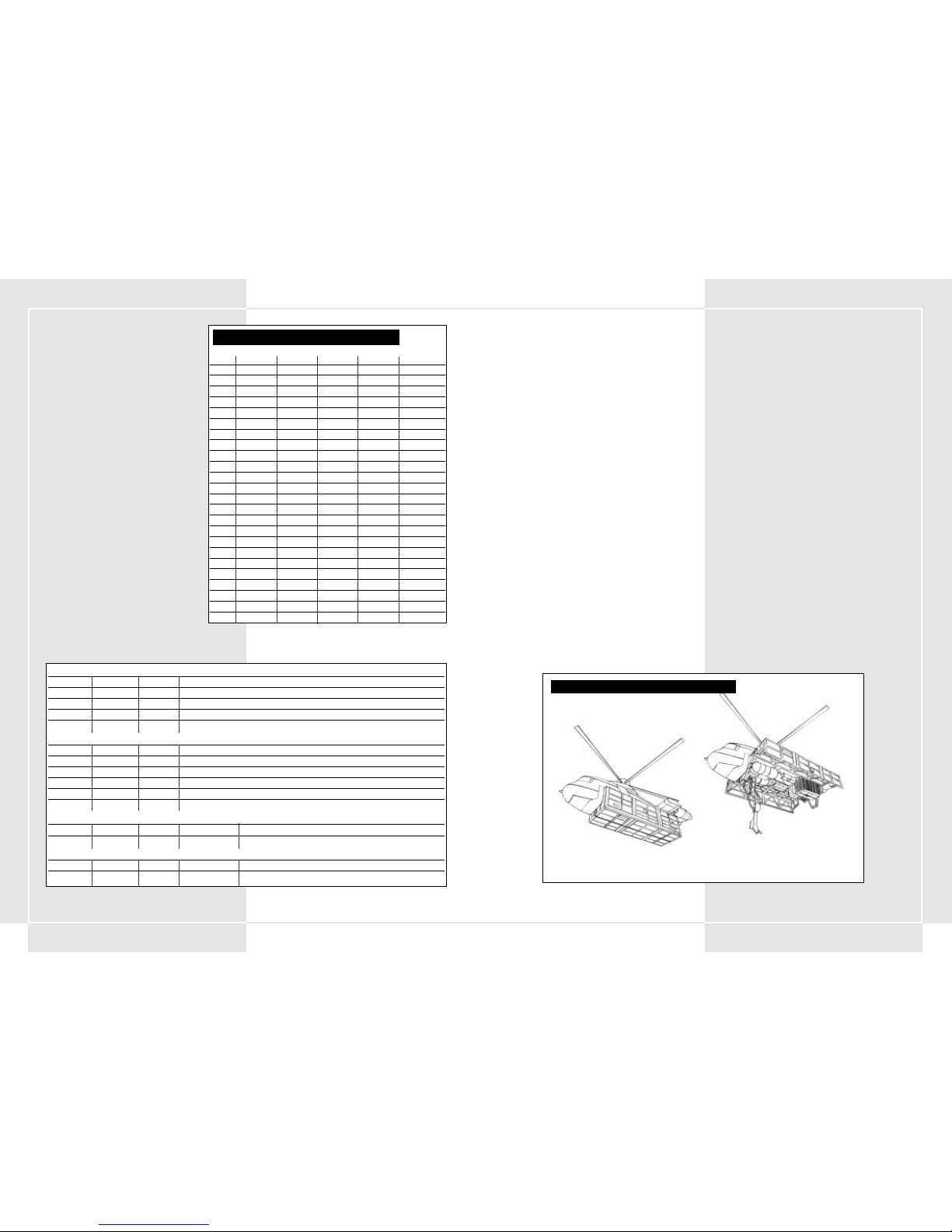
101100
9-1 AUFNAHME VON NACHSCHUB
Nachschub ist unerlässlich für die Aufrechterhaltung der
Leistungsfähigkeit des VT. Suchen Sie einen Platz, wo Sie sich im
Kampf mit Nachschub versorgen können. Die Versorgung mit
Nachschub während des Kampfes ist eine normale und schwierige
Aufgabe. Versuchen Sie, sich während des Kampfes nur dann mit
Nachschub zu versorgen, wenn Ihnen jemand Deckung gibt oder es
bereits spät in der Nacht ist. Der Nachschub für den VT wird per
Versorgungshubschrauber angeliefert, der zum Versorgungsbataillon
der Verstärkungsdivision gehört. Sie können nicht nur Kraftstoff
tanken und Ihr Geschossarsenal aufstocken, sondern der
Hubschrauber kann Sie auch mit neuer, zusätzlicher Panzerung und
mit Ersatzteilen versorgen. Um eine reibungslose
Nachschubabwicklung zu gewährleisten, müssen Sie eine
Nachschubanfrage ausfüllen und darin den geschätzten Bedarf
angeben, bevor Sie Ihre Mission in Angriff nehmen.
9-2 KLASSIFIZIERUNG VON NACHSCHUB
Für eine reibungslose Versorgung mit Nachschub muss der
Nachschub in fünf Hauptgruppen unterteilt werden. Abgesehen von
ein paar Ausnahmen, lassen sich die meisten Teile, die Sie vor einem
Kampf angefordert haben, in die folgenden drei Gruppen einteilen.
Diese werden in einer Bestellung an jeden VT verteilt.
1. Nachschub der Kategorie 1: Lebensmittel
2. Nachschub der Kategorie 3: Flüssigkeiten (Öl, Kraftstoff,
Schmierstoff)
3. Nachschub der Kategorie 5: Diverse Munition
Bevor er in den Kampf zieht, muss jeder Fahrer eine Liste des
benötigten Nachschubs erstellen und sich diese Liste von seinem
befehlshabenden Offizier genehmigen lassen.
9-3 NACHSCHUB PER
VERSORGUNGSHUBSCHRAUBER
Während des Kampfes müssen die VTs durch
Versorgungshubschrauber versorgt werden. Dieser gehört zum
Nachschubbataillon der Division. Wenn Sie Nachschub beantragen,
macht sich der Hubschrauber auf den Weg zum Aufenthaltsort Ihres
VT. Nach seiner Ankunft beginnt er über Ihnen zu schweben. Der
Fahrer muss den VT unter den Hubschrauber bewegen. Danach
erfolgt die Übergabe von Kraftstoff und Munition. Sie können auch
neue Panzerung und Ersatzteile für Ihren VT übernehmen.
9-4 MÖGLICHKEITEN UND
VORSICHTSMASSNAHMEN BEI DER AUFNAHME VON
NACHSCHUB
Da die Versorgung mit Nachschub etwas dauern kann, sind sowohl
Ihr VT als auch der Versorgungshubschrauber vorübergehend eine
leichte Beute. Um einen Angriff zu verhindern, müssen Sie die
Umgebung erkunden und die Augen offen halten. Versuchen Sie, die
Nachschubversorgung dort stattfinden zu lassen, wo Sie in Deckung
gehen können und nur wenig Feinde zu sehen sind. Diese Maßnahme
ist sehr wichtig, um zu verhindern, dass der Hubschrauber
abgeschossen wird, bevor er Sie mit Nachschub versorgt hat.
9-5 ERRICHTUNG DES
NACHSCHUBVERTEILUNGSZENTRUMS
Manchmal sorgen besondere Kampfumstände oder schlechtes
Wetter dafür, dass der Versorgungshubschrauber Sie nicht mit
Nachschub beliefern kann. Um solchen Fällen vorzubeugen, wurde
ein Nachschubverteilungszentrum hinter den eigenen Truppenlinien
errichtet. Vor dem Kampf wird der Ort dieses
Nachschubverteilungszentrums bestimmt. Die Errichtung erfolgt nach
folgenden Richtlinien:
1. Es ist groß genug, um den benötigten Nachschub lagern zu
können.
2. Ein geeigneter Weg verbindet die vorderen und hinteren Linien.
3. Es liegt vor dem Feind versteckt.
4. Es liegt vor feindlichen Angriffen geschützt.
Das Nachschubversorgungszentrum wird nur dort errichtet, wo eine
Frontlinie besteht und ein Lager existiert, das die Umgebung sichert.
Im Allgemeinen handelt es sich dabei um eine wirkliche Ausnahme.
Zu den grundlegenden Pflichten eines VT gehört das Auftanken per
Versorgungshubschrauber, sofern durchführbar.
ABSCHNITT 9. NACHSCHUB
VT-HUBSCHRAUBERVERSORGUNGSDIAGRAMM
Normaler Flug
Nachschubversorgung ist möglich
8-4 SENDEN EINER MELDUNG
1. Überlegen Sie sich, wen Sie anfunken möchten,
indem Sie den Kanal dieser Person mit Ihrem
Tuner anwählen.
2. Drücken Sie die Communication-Taste
(Funktaste) 1 (Rufen/Antworten), um Kontakt
aufzunehmen.
3. Die Person, die Sie angefunkt haben, antwortet.
4. Nachdem Sie sich vergewissert haben, dass Sie mit
der richtigen Person sprechen, bringen Sie Ihr
Anliegen vor.
5. Die andere Person prüft Ihr Anliegen.
6. Das Gespräch ist beendet.
8-5 EMPFANGEN EINER MELDUNG
1. Wenn eine Meldung hereinkommt, beginnt Ihr
Funkpanel zu blinken. Stellen Sie Ihren Tuner auf
den blinkenden Kanal ein. Damit können Sie die
Meldung der anderen Person hören.
2. Drücken Sie die Communication-Taste
(Funktaste) 1 (Rufen/Antworten), und antworten
Sie auf die Meldung.
3. Die andere Person erkennt, dass Sie geantwortet
haben, und bestätigt Ihre Meldung.
4. Nachdem Sie die Meldung gehört haben, drücken
Sie die Communication-Taste (Funktaste) 1
(Rufen/Antworten), um das Gespräch zu beenden.
8-6 WIEDERHOLEN DER MELDUNG
Wenn Sie nicht verstanden haben, was die andere
Person in ihrem Funkspruch gesagt hat, drücken Sie die
Communication-Taste (Funktaste) 2, um die andere
Person zu bitten, ihren Funkspruch zu wiederholen.
Wenn das Funkpanel blinkt (als Zeichen dafür, dass die
Leitungen frei sind), können Sie Ihr Anliegen
vorbringen. Sobald Sie die Communication-Taste
(Funktaste) 1 drücken, ist der Funkverkehr beendet
und die Leitung wird gesperrt.
KANALEINSTELLUNGEN AUF DEM FUNKPANEL
Funkpanel 1 Funkpanel 2 Funkpanel 3 Funkpanel 4 Funkpanel 5
MIS00
MIS01
MIS02
MIS03 Befehl Nachschub VT Commander
MIS04 Befehl Nachschub VT Commander
MIS05 Befehl Nachschub VT Commander
MIS06 Befehl Nachschub VT Commander
MIS07 Befehl Nachschub VT Commander
MIS08 Befehl Nachschub VT Commander
MIS09 Befehl Nachschub VT Commander
MIS10 Befehl Nachschub VT Commander
MIS11 Befehl Nachschub VT Commander
MIS12 Befehl Nachschub Wingman 1 Wingman 2 Wingman 1/2
MIS13 Befehl Nachschub Wingman 1 Wingman 2 Wingman 1/2
MIS14 Befehl Nachschub Wingman 1 Wingman 2 Wingman 1/2
MIS15 Befehl Nachschub Wingman 1 Wingman 2 Wingman 1/2
MIS16 Befehl Nachschub Wingman 1 Wingman 2 Wingman 1/2
MIS17 Befehl Nachschub Spionagedivision
MIS18 Befehl Nachschub Wingman 1 Wingman 2 Wingman 1/2
MIS19 Befehl Nachschub Wingman 1 Wingman 2 Wingman 1/2
MIS20 Befehl Nachschub
MIS21 Befehl Nachschub Wingman 1 Wingman 2 Wingman 1/2
MIS22 Befehl Nachschub Wingman 1 Wingman 2 Wingman 1/2
MIS23 Befehl Nachschub Wingman 1 Wingman 2 Wingman 1/2
RUFSIGNALLISTE (gedruckt 2080)
Gruppe Rufsignal Englischer Name Formaler Name
Spieler (Platoon) Oscar 3 Oscar 3 7. Spezialpanzerdivision, 34. Spezialpanzerbataillon, 6. Spezialpanzerkompanie, 1. Platoon 3. VT
Commander Oscar 1 Oscar 1 7. Spezialpanzerdivision, 34. Spezialpanzerbataillon, 6. Spezialpanzerkompanie, 1. Platoon 1. VT
Hauptbataillon Argus Argus 7. Spezialpanzerdivision, 34. Spezialpanzer-Hauptbataillon
Nachschub Wagonmaster Wagonmaster 7. Spezialpanzerdivision, Nachschubverstärkungsbataillon
RUFSIGNALLISTE (gedruckt 2082)
Spieler (Platoon) Xray 1 Xray 1 7. Spezialpanzerdivision, 34. Spezialpanzerbataillon, 6. Spezialpanzerkompanie, 1. Platoon 1. VT
Wingman 1 Xray 2 Xray 2 7. Spezialpanzerdivision, 34. Spezialpanzerbataillon, 6. Spezialpanzerkompanie, 1. Platoon 2. VT
Wingman 2 Xray 3 Xray 3 7. Spezialpanzerdivision, 34. Spezialpanzerbataillon, 6. Spezialpanzerkompanie, 1. Platoon 3. VT
Hauptbataillon Argus Argus 7. Spezialpanzerdivision, 34. Spezialpanzer-Hauptbataillon
Nachschub Wagonmaster Wagonmaster 7. Spezialpanzerdivision, Nachschubverstärkungsbataillon
Spion Schwarze Witwe Schwarze Witwe ??????????
FUNKTASTEN (2080)
Funktaste 1 Funktaste 2 Funktaste 3 Funktaste 4 Funktaste 5
Rufen/Antworten Wiederholen Nachschubanforderung Verstärkungsanforderung
FUNKTASTEN (2082)
Funktaste 1 Funktaste 2 Funktaste 3 Funktaste 4 Funktaste 5
Rufen/Antworten Wiederholen Nachschubanforderung
Page 53

103102
10-1 FÜHRUNGSPFLICHTEN
Dem Commander obliegen die Erteilung von Befehlen an seine
Truppen und die Erfüllung seiner ihm auferlegten Mission.
Commander gewinnen das Vertrauen ihrer Truppen durch solide
Führungseigenschaften und die Aufrechterhaltung einer starken
und stabilen Division. Dadurch können sie die Fähigkeiten ihrer
VTs verbessern.
10-2 ERFORDERLICHE QUALITÄTEN EINES
COMMANDERS
Dem Commander obliegt die Erfüllung seiner ihm zugeteilten
Mission. Außerdem ist er für seine Truppen verantwortlich. Ein
Commander muss seine Truppen, Ausrüstung, Taktiken und
Strategien sehr gut kennen und außerdem noch ein
herausragender VT-Fahrer sein. Zu den wichtigsten Aufgaben
eines Commanders gehört seine Fähigkeit, das Vertrauen seiner
Truppen zu gewinnen. Er muss ihnen ein Vorbild sein und sie mit
starker Hand durch die Mission führen. Daneben gilt es, auch in
schweren Situationen immer einen kühlen Kopf zu bewahren. Im
Kampf muss er einen starken Willen und eine scharfe
Urteilsfähigkeit unter Beweis stellen. Er muss schnell und
entschlossen handeln. Zögert ein Commander im Kampf,
bekommen seine Truppen Angst und verlieren die Zuversicht.
Gerade deshalb muss er die Mission, mit der er betraut wurde,
genauestens analysieren und fähig sein, unabhängig zu planen.
10-3 BEFEHLSERTEILUNG WÄHREND DES
KAMPFES
Der Platoon Commander muss jede einzelne Truppe über
Pflichten, Aufgaben und Erwartungen an deren
Einsatzbereitschaft aufklären. Er muss seine Truppen so
befehligen, dass sie ihr Bestes geben. Auf dieser Grundlage kann
er einfache Befehle erteilen, die die Ausführung von
Kampfstrategien deutlich erleichtern. Der Platoon Commander
muss vorschriftsgemäß seine Befehle per Funk über die
Communication-Tasten (Funktasten) 4 oder 5 erteilen. Dies
sorgt für einen reibungsloseren Funkverkehr. Insgesamt gibt es
vier verschiedene Befehle, die voreingestellt werden können. Je
nach Schlachtplan muss sich der Platoon Commander für zwei
dieser Befehle entscheiden.
Dazu gehören vier Schlüsselbefehle (von denen sich der Platoon
Commander zwei aussuchen muss):
1. Auflösen und Abziehen
Dieser Befehl besagt, dass sich die Truppen aus dem
Kampfgebiet zu entfernen haben. Wird der VT des Platoons
beschädigt, sollte das Platoon so schnell wie möglich
abziehen. Der Platoonführer trägt die Verantwortung für
seine Befehle und muss gleichzeitig seine Männer
beschützen. Er muss also alles in seiner Macht Stehende tun,
um seine Männer am Leben zu erhalten.
2. Verstärkung
Das Platoon muss seinen VT einsetzen, um einer anderen
Truppe Verstärkung zu leisten, zum Beispiel in Fällen, in
denen sie mit anderen Streitkräften kooperiert, wenn
Kontakt zum Feind hergestellt wurde u.s.w. Dies alles dient
dazu, die Streitkraft des Platoons zu maximieren. Der
Platoon Commander kennt die Vorschriften und hat sie
bereits in der Praxis sowie im Rahmen seiner
Befehlskompetenz eingesetzt. Außerdem ist er für den
Anstieg des Ausbildungsniveaus seiner Truppen
verantwortlich.
3. Angriff
Dieser Befehl bedeutet, dass das Hauptziel angegriffen
werden soll. Der Platoon Commander erteilt diesen Befehl
den Umständen entsprechend. Hierbei muss er seinen
Truppen mit gutem Beispiel vorangehen. Hauptaufgabe des
gesamten Platoons ist es, dieses Ziel zu erreichen. In Fällen,
in denen es mehrere Ziele gibt, erleichtert die Erteilung von
Befehlen das Erreichen der Missionsziele.
4. Versprengen
Wenn Sie damit rechnen, dass der Feind im Anmarsch ist,
können Sie auch Befehl geben, dass sich die Truppen
versprengen sollen. Dieser Befehl kann ausgesprochen
nützlich sein, wenn die Topografie des Kampfgebiets dies
erfordert oder Sie große Gebiete erkunden müssen.
WHEN USING THE PLASMA TORCH
ABSCHNITT 10. FÜHRUNG
PLATOON-BEFEHL: AUFLÖSEN UND ABZIEHEN
PLATOON-BEFEHL: VERSTÄRKUNG
PLATOON-BEFEHL: ANGRIFF
PLATOON-BEFEHL: VERSPRENGEN
Wingman 1
Wingman 2
Platoon Commander
Wingman 1
Wingman 2
Platoon Commander
Wingman 1
Wingman 2
Platoon Commander
Wingman 1
Wingman 2
Platoon Commander
Page 54

105104
WHEN USING THE PLASMA TORCH
TECHNISCHER ANHANG
COCKPIT: 1. GENERATION
Vordere Hinderniswarnleuchte
Mehrfachmonitor
Unterwaffe 1 Bezeichnung
Unterwaffe 1 verbleibende Einsätze
Hauptwaffe 1 Bezeichnung
Hauptwaffe 1 verbleibende Magazine
Hauptwaffe 1 verbleibende Munition
Interne Feuerwarnleuchte
Rechte Hinderniswarnleuchte
Linke Hinderniswarnleuchte
Hauptwaffe 2 Bezeichnung
Hauptwaffe 2 verbleibende Magazine
Hauptwaffe 2 verbleibende Munition
Hauptwaffe 3 Bezeichnung
Hauptwaffe 3 verbleibende Magazine
Hauptwaffe 3 verbleibende Munition
Funkleuchten 1–5
Batteriemesser
Motordrehzahlmesser
Geschwindigkeitsmesser
Hauptenergiemesser
Schadensleuchte
Sub-Monitor
Schaltleuchte
Digitaler
Geschwindigkeitsmesser
Deaktivierung
Stabilisatorbegrenzung
Tuner
Unterwaffe 2 Bezeichnung
Unterwaffe 2 verbleibende Einsätze
Subenergie-Tankmesser 1
Nebentank 1
angebracht oder
nicht
Nebentank 1 im Einsatz
Subenergie-Tankmesser 2
Nebentank 2
angebracht oder
nicht
Nebentank 2 im Einsatz
Unterwaffe 3 Bezeichnung
Unterwaffe 3 verbleibende Einsätze
Düppel verbleibende Einsätze
WHEN USING THE PLASMA TORCH
COCKPIT: 2. GENERATION
Vordere Hinderniswarnleuchte
Deaktivierung Stabilisatorbegrenzung
Mehrfachmonitor
Hauptwaffe Bezeichnung
Hauptwaffe 1 verbleibende Magazine
Hauptwaffe 1 verbleibende Munition
Interne Feuerwarnleuchte
Interne Feuerwarnleuchte
Rechte Hinderniswarnleuchte
Linke Hinderniswarnleuchte
Funkleuchten 1-5
Batteriemesser
Overdrive-Leuchte
Motordrehzahlmesser
Geschwindigkeits
messer
Hauptenergiemesser
Schadensanzeiger
Sub-Monitor
Schaltanzeiger
Digitaler Geschwindigkeitsmesser
Tuner
Unterwaffe 1 Bezeichnung
Unterwaffe 1 verbleibende Einsätze
Subenergie-Tankmesser
Nebentank 1 im Einsatz
Nebentank 1
Verfügbarkeit
Nebentank 2 im
Einsatz
Nebentank 2
Verfügbarkeit
Düppel verbleibende Einsätze
HAUPTMONITORDARSTELLUNG: 2. GENERATION
TIME . . . . . . . . . . . . . . . . . . . . . . . . . . . . . Verbleibende Zeit
FSS . . . . . . . . . . . . . . . . . . . . . . . . . . . . . . . Zeigt die Betriebsbereitschaft Ihres FSS-Systems an
SUB . . . . . . . . . . . . . . . . . . . . . . . . . . . . . . Unterwaffen-Info
. . . . . . . . . . . . . . . . . . . . . . . . . . . . . . . . . RELOAD – Sie sind mitten im Nachladevorgang
. . . . . . . . . . . . . . . . . . . . . . . . . . . . . . . . . HIT/MISS – Ihre Unterwaffe hat das Ziel getroffen oder verfehlt
SUPPLY INFO . . . . . . . . . . . . . . . . . . . . . . . . STAND BY – Nachschub wird vorbereitet
. . . . . . . . . . . . . . . . . . . . . . . . . . . . . . . . . REFUEL – Auftankvorgang aktiv
. . . . . . . . . . . . . . . . . . . . . . . . . . . . . . . . . COMPLETE – Der Auftankvorgang wurde beendet
DESTROYED . . . . . . . . . . . . . . . . . . . . . . . . . Ein Feind wurde vernichtet
MISSION COMPLETE . . . . . . . . . . . . . . . . . . . Zeigt an, in welchem Umfang die Mission abgeschlossen wurde
MAIN . . . . . . . . . . . . . . . . . . . . . . . . . . . . . Hauptwaffen-Info
. . . . . . . . . . . . . . . . . . . . . . . . . . . . . . . . . RELOAD – Sie sind mitten im Nachladevorgang
. . . . . . . . . . . . . . . . . . . . . . . . . . . . . . . . . HIT/MISS – Ihre Hauptwaffe hat das Ziel getroffen oder verfehlt
WARN . . . . . . . . . . . . . . . . . . . . . . . . . . . . . Warnt Sie davor, dass der Feind Ihren VT ins Visier genommen hat
SHOT . . . . . . . . . . . . . . . . . . . . . . . . . . . . . Zeigt an, dass der Feind eine nicht gelenkte Waffe auf Sie abgefeuert hat
BOMB . . . . . . . . . . . . . . . . . . . . . . . . . . . . . Warnt Sie davor, dass Bomben mit gekrümmter Geschossbahn im Anflug sind
MSSL . . . . . . . . . . . . . . . . . . . . . . . . . . . . . Warnt Sie davor, dass eine Lenkrakete im Anflug ist
NML . . . . . . . . . . . . . . . . . . . . . . . . . . . . . . Zeigt den Normalbetrieb an (Overdrive deaktiviert)
OVRD . . . . . . . . . . . . . . . . . . . . . . . . . . . . . Zeigt an, dass Sie sich im Overdrive-Modus befinden
HEAT . . . . . . . . . . . . . . . . . . . . . . . . . . . . . Zeigt an, dass sich die Batterie überhitzt hat
BLNC . . . . . . . . . . . . . . . . . . . . . . . . . . . . . Zeigt an, dass der Stabilisator langsam seinen kritischen Punkt erreicht
AREA . . . . . . . . . . . . . . . . . . . . . . . . . . . . . Zeigt an, dass Sie gerade das gekennzeichnete Kampfgebiet verlassen
x 1.00 . . . . . . . . . . . . . . . . . . . . . . . . . . . . . Hauptkamera-Vergrößerungsverhältnis
ANGLE OF DEPRESSION/ELEVATION
(TIEFENWINKEL/HÖHENWINKEL) . . . . . . . . . . . Zeigt den Kamerawinkel an
COMPASS . . . . . . . . . . . . . . . . . . . . . . . . . . Zeigt die Richtung an, in die Sie sich bewegen.
HAUPTMONITORDARSTELLUNG: 1. GENERATION
ZEIT . . . . . . . . . . . . . . . . . . . . . . . . . . . . . . Verbleibende Zeit
FSS . . . . . . . . . . . . . . . . . . . . . . . . . . . . . . . Zeigt die Betriebsbereitschaft Ihres FSS-Systems an
SUB . . . . . . . . . . . . . . . . . . . . . . . . . . . . . . Unterwaffen-Info
. . . . . . . . . . . . . . . . . . . . . . . . . . . . . . . . . RELOAD – Sie sind mitten im Nachladevorgang
. . . . . . . . . . . . . . . . . . . . . . . . . . . . . . . . . HIT/MISS – Ihre Unterwaffe hat das Ziel getroffen oder verfehlt
SUPPLY INFO (NACHSCHUBINFO) . . . . . . . . . . . STAND BY – Nachschub wird vorbereitet
. . . . . . . . . . . . . . . . . . . . . . . . . . . . . . . . . REFUEL – Auftankvorgang aktiv
. . . . . . . . . . . . . . . . . . . . . . . . . . . . . . . . . COMPLETE – Der Auftankvorgang ist abgeschlossen
DESTROYED . . . . . . . . . . . . . . . . . . . . . . . . . Ein Feind wurde vernichtet
MISSION COMPLETE (MISSION BEENDET . . . . . . Zeigt an, in welchem Umfang die Mission abgeschlossen wurde
MAIN . . . . . . . . . . . . . . . . . . . . . . . . . . . . . Hauptwaffen-Info
. . . . . . . . . . . . . . . . . . . . . . . . . . . . . . . . . RELOAD – Sie sind mitten im Nachladevorgang
. . . . . . . . . . . . . . . . . . . . . . . . . . . . . . . . . HIT/MISS – Ihre Hauptwaffe hat das Ziel getroffen oder verfehlt
WARN . . . . . . . . . . . . . . . . . . . . . . . . . . . . . Warnt Sie davor, dass der Feind Ihren VT im Visier hat
SHOT . . . . . . . . . . . . . . . . . . . . . . . . . . . . . Zeigt an, dass der Feind eine nicht gelenkte Waffe auf Sie abgefeuert hat
BOMB . . . . . . . . . . . . . . . . . . . . . . . . . . . . . Warnt Sie davor, dass Bomben mit gekrümmter Geschossflugbahn im Anflug sind
MSSL . . . . . . . . . . . . . . . . . . . . . . . . . . . . . Warnt Sie davor, dass eine Lenkrakete im Anflug ist
NML . . . . . . . . . . . . . . . . . . . . . . . . . . . . . . Zeigt den Normalbetrieb an (Overdrive deaktiviert)
OVRD . . . . . . . . . . . . . . . . . . . . . . . . . . . . . Zeigt an, dass Sie sich im Overdrive-Modus befinden
HEAT . . . . . . . . . . . . . . . . . . . . . . . . . . . . . Zeigt an, dass sich die Batterie überhitzt hat
BLNC . . . . . . . . . . . . . . . . . . . . . . . . . . . . . Zeigt an, dass der Stabilisator langsam seinen kritischen Punkt erreicht
AREA . . . . . . . . . . . . . . . . . . . . . . . . . . . . . Zeigt an, dass Sie gerade das gekennzeichnete Kampfgebiet verlassen
4.63 . . . . . . . . . . . . . . . . . . . . . . . . . . . . . . Hauptkamera-Vergrößerungsverhältnis
ANGLE OF DEPRESSION/ELEVATION
(TIEFENWINKEL/HÖHENWINKEL) . . . . . . . . . . . Zeigt den Kamerawinkel an
COMPASS . . . . . . . . . . . . . . . . . . . . . . . . . . Zeigt die Richtung an, in die Sie sich bewegen.
Page 55

107106
HERSTELLERGARANTIE FÜR IHRE KOPIE DER XBOXSPIELSOFTWARE (“SPIEL”)
Garantie. Microsoft Corporation (“Microsoft”) garantiert, dass dieses
Spiel für einen Zeitraum von 90 Tagen ab Erwerb so funktioniert wie in
dem beigefügten Handbuch beschrieben. Diese Herstellergarantie ist
nichtig, falls Schwierigkeiten mit dem Spiel auf einen Unfall,
Missbrauch, Virus oder falsche Anwendung zurückzuführen sind.
Microsoft gibt keine anderen Garantien und macht keine weiteren
Versprechungen hinsichtlich des Spiels.
Ihre Ansprüche. Falls innerhalb des Garantiezeitraums von 90 Tagen ein
Problem mit dem Spiel auftritt, das unter diese Herstellergarantie fällt,
geben Sie das Spiel zusammen mit einer Kopie der OriginalVerkaufsquittung an den Händler zurück. Der Händler wird das Spiel
nach eigenem Ermessen entweder a) kostenlos reparieren oder
ersetzen oder b) den Kaufpreis zurückerstatten. Für jedes Ersatzspiel
gewährt Microsoft für die restliche Zeit des ursprünglichen
Garantiezeitraums oder für 30 Tage nach Erhalt die Garantie, wobei der
längere Zeitraum maßgebend ist. Microsoft kann für eventuelle
Schäden nicht haftbar gemacht werden, soweit Sie Beschädigungen
durch entsprechende Vorsichtsmaßnahmen hätten vermeiden können.
Gesetzliche Rechte. Möglicherweise haben Sie Rechte gegenüber
Ihrem Händler, auf die die Herstellergarantie von Microsoft keinen
Einfluss hat.
WENN SIE DAS SPIEL NICHT FÜR IHREN PERSÖNLICHEN GEBRAUCH
ERWORBEN HABEN (WENN SIE NICHT ALS VERBRAUCHER
HANDELN)
Die folgenden Bestimmungen gelten im größtmöglichen durch das
anwendbare Recht zugelassenen Umfang.
Keine weiteren Gewährleistungen. Microsoft und deren Lieferanten
lehnen alle anderen ausdrücklichen oder konkludenten
Gewährleistungen und Garantien bezüglich des Spiels und des
beigefügten Handbuchs ab.
Haftungsbeschränkung. Microsoft haftet in Fällen von Vorsatz, grober
Fahrlässigkeit, bei Verletzung von Leib oder Leben sowie bei
Ansprüchen nach dem Produkthaftungsgesetz nach den gesetzlichen
Vorschriften. Eine weitergehende Haftung von Microsoft besteht nicht.
Dies gilt für alle Haftungstatbestände einschließlich unerlaubter
Handlung.
Falls Sie Fragen bezüglich dieser Garantie haben, wenden Sie sich bitte
an Ihren Händler oder an Microsoft unter:
Microsoft Ireland Operations Limited
Sandyford Industrial Estate
Blackthorn Road
Dublin 18
Irland
Die in diesen Unterlagen enthaltenen Angaben und Daten, einschließlich Hinweise auf
URLs und weitere Internet-Websites, können ohne vorherige Ankündigung geändert
werden. Die in den Beispielen verwendeten Firmen, Organisationen, Produkte, Personen
und Ereignisse sind frei erfunden und jede Ähnlichkeit mit bestehenden Firmen,
Organisationen, Produkten, Personen oder Ereignissen ist rein zufällig, soweit nichts
anderes angegeben ist. Die Benutzer sind verantwortlich für das Einhalten aller
anwendbaren Urheberrechtsgesetze. Unabhängig von der Anwendbarkeit der
entsprechenden Urheberrechtsgesetze darf ohne ausdrückliche schriftliche Erlaubnis
der Microsoft Corporation kein Teil dieses Dokumentes für irgendwelche Zwecke
vervielfältigt oder in einem Datenempfangssystem gespeichert oder darin eingelesen
werden, unabhängig davon, auf welche Art und Weise oder mit welchen Mitteln
(elektronisch, mechanisch, durch Fotokopieren, Aufzeichnen usw.) dies geschieht.
Es ist möglich, dass Microsoft Rechte an Patenten bzw. angemeldeten Patenten, an
Marken, Urheberrechten oder sonstigem geistigen Eigentum besitzt, die sich auf den
fachlichen Inhalt dieses Dokuments beziehen. Das Bereitstellen dieses Dokuments gibt
Ihnen jedoch keinen Anspruch auf diese Patente, Marken, Urheberrechte oder auf
sonstiges geistiges Eigentum, es sein denn, dies wird ausdrücklich in den schriftlichen
Lizenzverträgen von Microsoft eingeräumt.
© 2003 Microsoft Corporation. Alle Rechte vorbehalten.
Microsoft, Xbox und die Xbox-Logos sind Marken oder eingetragene Marken der
Microsoft Corporation in den USA und/oder anderen Ländern.
Hergestellt unter Lizenz von Dolby Laboratories.
WHEN USING THE PLASMA TORCH
COCKPIT: 3. Generation
Vordere
Hinderniswarnleuchte
Deaktivierung
Stabilisatorbegrenzung
Mehrfachmonitor
Hauptwaffe Bezeichnung
Hauptwaffe 1 verbleibende Magazine
Hauptwaffe 1 verbleibende Munition
Interne Feuerwarnleuchte
Interne Feuerwarnleuchte
Rechte
Hinderniswarnleuchte
Linke
Hinderniswarnleuchte
Funkleuchten 1-5
Batteriemesser
Overdrive-Leuchte
Overdrive-Leuchte
Motordrehzahlmesser
Geschwindigkeits
messer
Hauptenergiemesser
Schadensanzeiger
Sub-Monitor
Schaltanzeiger
Digitaler Geschwindigkeitsmesser
Tuner
Unterwaffe 1 Bezeichnung
Unterwaffe 1 verbleibende Einsätze
Subenergie-Tankmesser 1
Nebentank 1
Verfügbarkeit
Subenergie-Tankmesser 2
Nebentank 2
Verfügbarkeit
Düppel verbleibende Einsätze
HAUPTMONITORDARSTELLUNG: 3. GENERATION
ZEIT . . . . . . . . . . . . . . . . . . . . . . . . . . Verbleibende Zeit
FSS . . . . . . . . . . . . . . . . . . . . . . . . . . . Zeigt die Betriebsbereitschaft Ihres FSS-Systems an
SUB . . . . . . . . . . . . . . . . . . . . . . . . . . Unterwaffen-Info
. . . . . . . . . . . . . . . . . . . . . . . . . . . . . RELOAD – Sie sind mitten im Nachladevorgang
. . . . . . . . . . . . . . . . . . . . . . . . . . . . . HAT/MISS – Ihre Unterwaffe hat das Ziel getroffen oder verfehlt
SUPPLY INFO . . . . . . . . . . . . . . . . . . . . STAND BY – Nachschub wird vorbereitet
. . . . . . . . . . . . . . . . . . . . . . . . . . . . . REFUEL – Auftankvorgang aktiv
. . . . . . . . . . . . . . . . . . . . . . . . . . . . . COMPLETE – Der Auftankvorgang wurde beendet
DESTROYED . . . . . . . . . . . . . . . . . . . . . Ein Feind wurde vernichtet
MISSION COMPLETE . . . . . . . . . . . . . . . Zeigt an, in welchem Umfang die Mission abgeschlossen wurde
MAIN . . . . . . . . . . . . . . . . . . . . . . . . . Hauptwaffen-Info
. . . . . . . . . . . . . . . . . . . . . . . . . . . . . RELOAD – Sie sind mitten im Nachladevorgang
. . . . . . . . . . . . . . . . . . . . . . . . . . . . . HIT/MISS – Ihre Hauptwaffe hat das Ziel getroffen oder verfehlt
WARN . . . . . . . . . . . . . . . . . . . . . . . . .Warnt Sie davor, dass der Feind Ihren VT ins Visier genommen hat
SHOT . . . . . . . . . . . . . . . . . . . . . . . . . Zeigt an, dass der Feind eine nicht gelenkte Waffe auf Sie abgefeuert hat
BOMB . . . . . . . . . . . . . . . . . . . . . . . . . Warnt Sie davor, dass Bomben mit gekrümmter Geschossbahn im Anflug sind
MSSL . . . . . . . . . . . . . . . . . . . . . . . . . Warnt Sie davor, dass eine Lenkrakete im Anflug ist
NML . . . . . . . . . . . . . . . . . . . . . . . . . . Zeigt den Normalbetrieb an (Overdrive deaktiviert)
OVRD . . . . . . . . . . . . . . . . . . . . . . . . . Zeigt an, dass Sie sich im Overdrive-Modus befinden
HEAT . . . . . . . . . . . . . . . . . . . . . . . . . Zeigt an, dass sich die Batterie überhitzt hat
BLNC . . . . . . . . . . . . . . . . . . . . . . . . . Zeigt an, dass der Stabilisator langsam seinen kritischen Punkt erreicht
AREA . . . . . . . . . . . . . . . . . . . . . . . . . Zeigt an, dass Sie gerade das gekennzeichnete Kampfgebiet verlassen
x 1.00 . . . . . . . . . . . . . . . . . . . . . . . . . Hauptkamera-Vergrößerungsverhältnis
ANGLE OF DEPRESSION/ELEVATION
(TIEFENWINKEL/HÖHENWINKEL) . . . . . . . Zeigt den Kamerawinkel an
COMPASS . . . . . . . . . . . . . . . . . . . . . . Zeigt die Richtung an, in die Sie sich bewegen.
Page 56

109108
INSTALACIÓN DEL CONTROLADOR . . . . . . . . . . . . . . . . . . . . . . . . . . . . . . . . . . . . . . . 110
Precauciones . . . . . . . . . . . . . . . . . . . . . . . . . . . . . . . . . . . . . . . . . . . . . . . . . . 110
Solución de problemas . . . . . . . . . . . . . . . . . . . . . . . . . . . . . . . . . . . . . . . . . . . 110
Montaje de la unidad derecha . . . . . . . . . . . . . . . . . . . . . . . . . . . . . . . . . . . . . 110
Montaje de la unidad izquierda . . . . . . . . . . . . . . . . . . . . . . . . . . . . . . . . . . . . 110
SECCIÓN 1. CONCEPTO DE VT Y DIVISIÓN PANZER ESPECIAL . . . . . . . . . . . . . . . . . . . . 112
1-1 Concepto de VT . . . . . . . . . . . . . . . . . . . . . . . . . . . . . . . . . . . . . . . . . . . . . . 112
1-2 Fundamentos del VT de uso militar . . . . . . . . . . . . . . . . . . . . . . . . . . . . . . . 112
1-3 Deberes de la Unidad Acorazada Especial . . . . . . . . . . . . . . . . . . . . . . . . . . 112
1-4 Formación de la División Panzer Especial . . . . . . . . . . . . . . . . . . . . . . . . . . 112
1-5 Operación del Pelotón de VT . . . . . . . . . . . . . . . . . . . . . . . . . . . . . . . . . . . 112
SECCIÓN 2. RESÚMEN DEL VT . . . . . . . . . . . . . . . . . . . . . . . . . . . . . . . . . . . . . . . . . . . . 113
2-1 Piezas básicas del VT . . . . . . . . . . . . . . . . . . . . . . . . . . . . . . . . . . . . . . . . . . 113
2-2 Sistema de control del VT . . . . . . . . . . . . . . . . . . . . . . . . . . . . . . . . . . . . . . 113
2-3 Tipos de VT . . . . . . . . . . . . . . . . . . . . . . . . . . . . . . . . . . . . . . . . . . . . . . . . . 114
2-4 Movimiento . . . . . . . . . . . . . . . . . . . . . . . . . . . . . . . . . . . . . . . . . . . . . . . . . 114
2-5 Depósito de combustible y depósitos de reserva . . . . . . . . . . . . . . . . . . . . 114
2-6 Consumo de combustible y tiempo de movimiento estimado . . . . . . . . . . 114
2-7 Blindaje defensivo . . . . . . . . . . . . . . . . . . . . . . . . . . . . . . . . . . . . . . . . . . . 114
2-8 Arma principal y arma secundaria . . . . . . . . . . . . . . . . . . . . . . . . . . . . . . . 114
2-9 Margen de peso máximo del armamento . . . . . . . . . . . . . . . . . . . . . . . . . . 114
2-10 Armamento cargado en el VT . . . . . . . . . . . . . . . . . . . . . . . . . . . . . . . . . . 115
2-11 Alcance de tiro del armamento con trayectoria curva
en el mapa de guerra . . . . . . . . . . . . . . . . . . . . . . . . . . . . . . . . . . . . . . . . . . . .120
2-12 Espoleta corta . . . . . . . . . . . . . . . . . . . . . . . . . . . . . . . . . . . . . . . . . . . . . . 120
2-13 Defensa antirradar . . . . . . . . . . . . . . . . . . . . . . . . . . . . . . . . . . . . . . . . . . 120
SECCIÓN 3a. FUNCIONES ESPECIALES
HASTA LA 2aª GENERACIÓN DEL COOS . . . . . . . . . . . . . . . . . . . . . . . . . . . . . . . . . . . . . 120
3-1 Adiciones al coos de 2ª
a
generación . . . . . . . . . . . . . . . . . . . . . . . . . . . . . .120
3-2 Función FSS (Sistema de disparo por estimación del objetivo) . . . . . . . . . 120
3-3 Función Overdrive (Superdirecta) . . . . . . . . . . . . . . . . . . . . . . . . . . . . . . . . 120
3-4 Función Stealth (Sigilo) . . . . . . . . . . . . . . . . . . . . . . . . . . . . . . . . . . . . . . . . 120
3-5 Armas guiadas . . . . . . . . . . . . . . . . . . . . . . . . . . . . . . . . . . . . . . . . . . . . . . 120
SECCIÓN 4. CONTROLES DEL VT . . . . . . . . . . . . . . . . . . . . . . . . . . . . . . . . . . . . . . . . . . 121
4-1 Secuencia de inicio . . . . . . . . . . . . . . . . . . . . . . . . . . . . . . . . . . . . . . . . . . . 121
4-2 Cuando se para el VT durante el inicio . . . . . . . . . . . . . . . . . . . . . . . . . . . . 121
Controles básicos . . . . . . . . . . . . . . . . . . . . . . . . . . . . . . . . . . . . . . . . . . . . . . . 122
4-3 Moverse y detenerse . . . . . . . . . . . . . . . . . . . . . . . . . . . . . . . . . . . . . . . . . 122
4-4 Aceleración y desaceleración . . . . . . . . . . . . . . . . . . . . . . . . . . . . . . . . . . . 122
4-5 Rotación . . . . . . . . . . . . . . . . . . . . . . . . . . . . . . . . . . . . . . . . . . . . . . . . . . . 122
4-6 Overdrive (Superdirecta) . . . . . . . . . . . . . . . . . . . . . . . . . . . . . . . . . . . . . . . 122
4-7 Función Slidestep (Deslizamiento) . . . . . . . . . . . . . . . . . . . . . . . . . . . . . . . 122
4-8 Limitaciones funcionales del deslizamiento . . . . . . . . . . . . . . . . . . . . . . . . 122
4-9 Regulador de inclinación de deslizamiento . . . . . . . . . . . . . . . . . . . . . . . . 122
4-10 Función Cut-off (Desconexión) . . . . . . . . . . . . . . . . . . . . . . . . . . . . . . . . . 122
4-11 Controles del manipulador . . . . . . . . . . . . . . . . . . . . . . . . . . . . . . . . . . . . 123
Pantalla del VT . . . . . . . . . . . . . . . . . . . . . . . . . . . . . . . . . . . . . . . . . . . . . . . . . 124
4-12 Cambio de la cámara principal . . . . . . . . . . . . . . . . . . . . . . . . . . . . . . . . . 124
4-13 Polvo y suciedad en la cámara principal . . . . . . . . . . . . . . . . . . . . . . . . . . 124
4-14 Funciones de la pantalla secundaria . . . . . . . . . . . . . . . . . . . . . . . . . . . . . 125
4-15 Equipo de visión nocturna . . . . . . . . . . . . . . . . . . . . . . . . . . . . . . . . . . . . 125
JCS (Sistema de mando completo) . . . . . . . . . . . . . . . . . . . . . . . . . . . . . . . . . . 125
4-16 Resumen de JCS . . . . . . . . . . . . . . . . . . . . . . . . . . . . . . . . . . . . . . . . . . . . . 125
4-17 Pantalla múltiple . . . . . . . . . . . . . . . . . . . . . . . . . . . . . . . . . . . . . . . . . . . . 126
4-18 Información mostrada en la pantalla múltiple . . . . . . . . . . . . . . . . . . . . . 126
Procedimientos de emergencia . . . . . . . . . . . . . . . . . . . . . . . . . . . . . . . . . . . . . . . . . 127
4-19 Configuración de la evacuación . . . . . . . . . . . . . . . . . . . . . . . . . . . . . . . . 127
4-20 Interruptor del eyector de emergencia . . . . . . . . . . . . . . . . . . . . . . . . . . 127
4-21 Procedimientos de escape de emergencia en ríos o mares . . . . . . . . . . . 127
4-22 Incendio en el casco . . . . . . . . . . . . . . . . . . . . . . . . . . . . . . . . . . . . . . . . . 127
SECCIÓN 5. ATAQUE DEL VT . . . . . . . . . . . . . . . . . . . . . . . . . . . . . . . . . . . . . . . . . . . . 128
5-1 Apuntar y disparar con armas . . . . . . . . . . . . . . . . . . . . . . . . . . . . . . . . . . 128
5-2 Función Lock-On (Bloqueo de objetivo) . . . . . . . . . . . . . . . . . . . . . . . . . . . 128
5-3 Puntería en combate cercano . . . . . . . . . . . . . . . . . . . . . . . . . . . . . . . . . . 128
5-4 FSS (Sistema de disparo por estimación del objetivo) . . . . . . . . . . . . . . . . 129
5-5 Alcances de tiro de diferentes armas . . . . . . . . . . . . . . . . . . . . . . . . . . . . . 129
5-6 Notas acerca del disparo con alcance de tiro eficaz . . . . . . . . . . . . . . . . . 129
5-7 Utilizar un alcance de tiro eficaz . . . . . . . . . . . . . . . . . . . . . . . . . . . . . . . . 130
5-8 Ataque de tierra arrasada . . . . . . . . . . . . . . . . . . . . . . . . . . . . . . . . . . . . . 130
5-9 Cambio de arma . . . . . . . . . . . . . . . . . . . . . . . . . . . . . . . . . . . . . . . . . . . . 130
5-10 Recargar armas con cargador . . . . . . . . . . . . . . . . . . . . . . . . . . . . . . . . . . 130
SECCIÓN 6. MOVIMIENTO DEL VT . . . . . . . . . . . . . . . . . . . . . . . . . . . . . . . . . . . . . . . . 131
6-1 En general . . . . . . . . . . . . . . . . . . . . . . . . . . . . . . . . . . . . . . . . . . . . . . . . . . 131
6-2 Utilizar la meteorología y la topografía . . . . . . . . . . . . . . . . . . . . . . . . . . . 131
CONFIGURACIÓN DEL CONTROLADOR DE STEEL BATTALION . . . . . . . . . . . . . . . . . . . . 132
SECCIÓN 7. PREPARATIVOS DE LA ESTREGIA DEL PELOTÓN . . . . . . . . . . . . . . . . . . . . . 134
7-1 Órdenes . . . . . . . . . . . . . . . . . . . . . . . . . . . . . . . . . . . . . . . . . . . . . . . . . . . . 134
7-2 Análisis de la misión . . . . . . . . . . . . . . . . . . . . . . . . . . . . . . . . . . . . . . . . . . 134
7-3 Elección del armamento . . . . . . . . . . . . . . . . . . . . . . . . . . . . . . . . . . . . . . . 134
7-4 Selección de blindaje adicional y armamento secundario . . . . . . . . . . . . . 134
7-5 Elección del VT . . . . . . . . . . . . . . . . . . . . . . . . . . . . . . . . . . . . . . . . . . . . . . 134
7-6 Adjuntar depósitos de combustible y blindaje adicionales . . . . . . . . . . . . 134
7-7 Solicitudes de suministro . . . . . . . . . . . . . . . . . . . . . . . . . . . . . . . . . . . . . . 134
7-8 Provisiones de alimentos del VT . . . . . . . . . . . . . . . . . . . . . . . . . . . . . . . . 134
7-9 Llevar efectos personales a la cabina . . . . . . . . . . . . . . . . . . . . . . . . . . . . 134
SECCIÓN 8. TRANSMISIONES DE RADIO
8-1 Resumen . . . . . . . . . . . . . . . . . . . . . . . . . . . . . . . . . . . . . . . . . . . . . . . . . . . 135
8-2 Canales preestablecidos . . . . . . . . . . . . . . . . . . . . . . . . . . . . . . . . . . . . . . . 135
8-3 Procedimientos de la comunicación por radio . . . . . . . . . . . . . . . . . . . . . 135
8-4 Enviar un mensaje . . . . . . . . . . . . . . . . . . . . . . . . . . . . . . . . . . . . . . . . . . . 130
8-5 Recibir un mensaje . . . . . . . . . . . . . . . . . . . . . . . . . . . . . . . . . . . . . . . . . . 130
8-6 Repetir el mensaje . . . . . . . . . . . . . . . . . . . . . . . . . . . . . . . . . . . . . . . . . . 130
SECCIÓN 9. SUMINISTROS . . . . . . . . . . . . . . . . . . . . . . . . . . . . . . . . . . . . . . . . . . . . . . 137
9-1 Aceptar suministros . . . . . . . . . . . . . . . . . . . . . . . . . . . . . . . . . . . . . . . . . . 137
9-2 Clasificar suministros . . . . . . . . . . . . . . . . . . . . . . . . . . . . . . . . . . . . . . . . . 137
9-3 Suministro mediante helicóptero de suministros . . . . . . . . . . . . . . . . . . . . 137
9-4 Opciones y precauciones al recibir suministros . . . . . . . . . . . . . . . . . . . . . 137
9-5 Abrir el Centro de provisión de suministros . . . . . . . . . . . . . . . . . . . . . . . 137
SECCIÓN 10. LIDERAZGO . . . . . . . . . . . . . . . . . . . . . . . . . . . . . . . . . . . . . . . . . . . . . . . 138
10-1 Deberes del liderazgo . . . . . . . . . . . . . . . . . . . . . . . . . . . . . . . . . . . . . . . . 138
10-2 Cualidades necesarias para el mando . . . . . . . . . . . . . . . . . . . . . . . . . . . . 138
10-3 Órdenes durante la batalla . . . . . . . . . . . . . . . . . . . . . . . . . . . . . . . . . . . . 138
APÉNDICE TÉCNICO . . . . . . . . . . . . . . . . . . . . . . . . . . . . . . . . . . . . . . . . . . . . . . . . . . 140
Cabina: 1aGeneración . . . . . . . . . . . . . . . . . . . . . . . . . . . . . . . . . . . . . . . . . . . 140
Pantalla principal: 1aª Generación . . . . . . . . . . . . . . . . . . . . . . . . . . . . . . . . . . 140
Cabina: 2ªaGeneración . . . . . . . . . . . . . . . . . . . . . . . . . . . . . . . . . . . . . . . . . . . 141
Pantalla principal: 2aª Generación . . . . . . . . . . . . . . . . . . . . . . . . . . . . . . . . . . . 141
Cabina: 3ªaGeneración . . . . . . . . . . . . . . . . . . . . . . . . . . . . . . . . . . . . . . . . . . . 142
Pantalla principal: 3aª Generación . . . . . . . . . . . . . . . . . . . . . . . . . . . . . . . . . . 142
Garantía . . . . . . . . . . . . . . . . . . . . . . . . . . . . . . . . . . . . . . . . . . . . . . . . . . . . . . 143
Atención al cliente . . . . . . . . . . . . . . . . . . . . . . . . . . . . . . . . . . . . . . . . . . . . . . 181
ESPAÑOL
ANTES DE UTILIZAR EL JUEGO
Gracias por comprar STEEL BATTALION. Lea los manuales de
instrucciones antes de empezar a jugar. Después de leer los
manuales, téngalos a mano en lugar seguro para que pueda
consultarlos rápida y fácilmente.
ADVERTENCIAS
• Guarde la unidad y todos los componentes lejos del alcance
de los niños.
• No abra ni modifique la unidad ni los componentes.
• No derrame agua sobre la unidad o los componentes.
• Guarde la unidad y los componentes en un lugar seco y
libre de polvo.
•Si aparece algún problema, detenga el uso de inmediato.
ÍNDICE
INFORMACIÓN DE SEGURIDAD
Información sobre los ataques epilépticos
fotosensibles
Un porcentaje escaso de personas puede sufrir un ataque
cuando se exponen a ciertas imágenes visuales, entre las que se
incluyen las imágenes o las luces parpadeantes que aparecen
en los videojuegos. Incluso aquellas personas que no tienen un
historial de este tipo de ataques o epilepsia pueden ser
propensos a estos “ataques epilépticos fotosensibles” cuando
fijan la vista en un videojuego.
Estos ataques tienen varios síntomas: mareos, visión alterada,
tics nerviosos en la cara o los ojos, temblores de brazos o
piernas, desorientación, confusión o pérdida momentánea de la
conciencia. Además, pueden ocasionar una pérdida del
conocimiento o incluso convulsiones que conduzcan a una
lesión propiciada por una caída o un golpe con algún objeto
cercano.
Si sufre cualquiera de estos síntomas, deje de jugar
inmediatamente y consulte a un médico. Los padres deben
observar a sus hijos o preguntarles si han sufrido los síntomas
antes mencionados; los niños y adolescentes tienen más
posibilidades de sufrir estos ataques que los adultos.
Para reducir el riesgo de ataques epilépticos fotosensibles es
aconsejable sentarse a una distancia considerable de la
pantalla del televisor, utilizar una pantalla más pequeña, jugar
en una habitación bien iluminada y no jugar cuando se está
somnoliento o cansado.
Si usted o algún familiar suyo posee un historial de ataques
epilépticos, consulte a su médico antes de jugar.
Información adicional importante sobre la salud y seguridad
El manual de instrucciones de la Xbox contiene información
importante sobre la salud y seguridad que debería leer y
asimilar antes de utilizar este software.
Evite daños en su televisor
No utilice este software en determinados televisores.
Algunos aparatos, sobre todo los de proyección frontal o
posterior, pueden sufrir daños si se utilizan para videojuegos,
incluidos los juegos de la Xbox. Las imágenes estáticas
presentadas durante el desarrollo normal del juego pueden
“quemar” la pantalla, lo que origina una sombra permanente de
este tipo de imágenes, incluso cuando no se está jugando. Se
pueden producir daños similares debido a las imágenes
estáticas que se crean al poner el videojuego en pausa.
Consulte el manual de usuario del televisor para saber si se
pueden utilizar videojuegos con total garantía y seguridad. Si
no encuentra esta información en el manual, póngase en
contacto con el distribuidor o el fabricante del televisor para
saber si se pueden utilizar videojuegos de forma segura en el
aparato.
Queda totalmente prohibida la copia, ingeniería inversa,
transmisión, reproducción pública, alquiler, partida a cambio
de dinero o incumplimiento de la protección de copia sin
autorización previa.
Page 57

111110
INSTALACIÓN DEL CONTROLADOR
PRECAUCIONES
• No conecte más de 2 controladores de
STEEL
BATTALION
en la misma unidad Xbox.
• No toque la palanca de puntería (de mira) ni la de selección
al conectar el controlador de
STEEL BATTALION
o
encender el equipo.
• Al conectar las piezas del controlador de
STEEL
BATTALION
no confunda la unidad izquierda con la unidad
derecha. Asegúrese de conectarlas en sus posiciones correctas.
• El controlador de
STEEL BATTALION
está fabricado con
pequeñas piezas de precisión. No coloque nada encima ni lo
ponga en un estante inestable.
•Apague siempre la consola Xbox antes de quitar el controlador
de
STEEL BATTALION
.
• Cuando limpie el controlador de
STEEL BATTALION
,
asegúrese de apagarlo previamente. Limpie el controlador con
un paño suave y seco. No utilice disolvente porque puede
producir decoloración o deformación de la unidad.
•Evite que caiga el controlador de
STEEL BATTALION
.
• No tuerza con mucha fuerza el cable; retírelo o ponga algo
pesado sobre él.
• Al quitar el cable, asegúrese de sujetar el área que se conecta
a la consola Xbox para retirar el cable.
• No guarde el controlador de
STEEL BATTALION
en
lugares con mucho calor o frío, o en los que pueda haber agua
o humedad.
• Utilice el controlador de
STEEL BATTALION
sólo para el
propósito para el que está concebido.
SOLUCIÓN DE PROBLEMAS
Antes de enviar el controlador de
STEEL BATTALION
para
su reparación, realice las siguientes comprobaciones:
El controlador no responde:
•Vuelva a conectarlo desde el principio y reinicie el equipo.
El indicador LED de la palanca de puntería no se enciende:
• Mueva la palanca de cambio a una posición en la que el
indicador LED se encienda. Dejar la palanca en una posición
en la que no se encienda durante períodos largos puede
ocasionar que el indicador LED deje de encenderse.
MONTAJE DE LA UNIDAD DERECHA
Advertencia: no confunda las unidades derecha e izquierda.
Asegúrese de conectarlas en sus posiciones correctas.
1. Conecte la unidad central y la unidad derecha insertando el
cable conector en las clavijas de ambas unidades.
ATENCIÓN: debe conectar el extremo del cable en la unidad
central con la orientación correcta. Compruebe la dirección
en la que debe estar orientado el cable antes de intentar
conectarlo en la unidad.
2. Asegúrese de insertar los extremos del cable conector hasta
el fondo en las clavijas. De no hacerlo así, el controlador
podría no funcionar.
3. Compruebe que el cable del conector no queda pellizcado
entre las dos unidades.
ADVERTENCIA: si inserta el cable conector demasiado
bruscamente, puede romper los cables en el interior, con lo
que la unidad quedaría inservible.
4. Sujete firmemente la cubierta de la unidad conectora. En la
parte posterior de cada cubierta de unidad conectora aparece
escrita una R o L pequeña. Utilice la cubierta R con la unidad
derecha y la cubierta L con la unidad izquierda.
5. Inserte los tornillos en los cuatro orificios de la cubierta de
la unidad conectora. Utilice para este fin la llave Alan que hay
sujeta a la parte inferior de la unidad central.
6. Apriete los tornillos y habrá finalizado.
MONTAJE DE LA UNIDAD IZQUIERDA
Siga los mismos pasos que para conectar la unidad derecha
(arriba).
MONTAJE DEL CONTROLADOR DE STEEL BATTALION
CONTROLADOR DE STEEL BATTALION COMPLETAMENTE MONTADO
Conecte la unidad central y la unidad derecha insertando el cable conector en las clavijas de ambas unidades.
Asegúrese de insertar los extremos del cable conector hasta el fondo en las clavijas.
Sujete firmemente la cubierta de la unidad conectora.
Inserte los tornillos en los cuatro orificios de la cubierta de la unidad conectora y apriételos.
A
B
C
D
EFG
H
Page 58

113112
2-1 PIEZAS BÁSICAS DEL VT
Los VT están formados básicamente por tres unidades
principales:
1. Cuerpo principal
2. Patas
3. Unidad de armamento
Algunas unidades de armamento se montan directamente en el
cuerpo principal, mientras que otras funcionan de forma
independiente.
2-2 SISTEMA DE CONTROL DEL VT
El funcionamiento del VT se controla con un SO (sistema
operativo) conocido como COOS. Controla el nivelador de las
patas, así como el sistema de puntería de varias armas. Incluso
aunque el tipo de VT sea el mismo, cuando el SO cargado sea
diferente el rendimiento en el campo de batalla disminuirá
considerablemente. El COOS, perfeccionado tanto en numerosos
experimentos como en el campo de batalla, es uno de los grandes
secretos del ejército. Los pilotos deben tener en cuenta este
hecho, por lo que si utilizan el sistema de eyección durante una
batalla deberán destruir el VT para proteger esta tecnología.
SECCIÓN 1. CONCEPTO DE VT Y DIVISIÓN PANZER ESPECIAL SECCIÓN 2. RESÚMEN DEL VT
DIAGRAMA DE LA ESTRUCTURA DEL VT
Área de junta esférica (eje x)
ejes x,y
eje z
eje x
eje x
Los cambios de dirección se realizan con esas piezas
Área de junta esférica
Área de junta esférica
1-1 CONCEPTO DE VT
La historia del VT (tanque vertical) es breve y sólo se ha utilizado
realmente como arma durante los últimos ocho años. No obstante,
debido al hecho de que muchas organizaciones diferentes han
empezado a utilizar el VT, tiene un gran potencial como arma militar.
El desarrollo militar ha llegado a saturarse y, debido a la reducción
de armamento, muchos proyectos militares y tropas innecesarias han
sufrido recortes. El VT, con su impresionante potencia de fuego y la
posibilidad de ser pilotado por una persona, se utilizará para
reemplazar tanques acorazados y no cabe duda de que será el arma
principal de la mayoría de organizaciones.
1-2 FUNDAMENTOS DEL VT DE USO MILITAR
Hasta la fecha, el VT no se ha utilizado de forma generalizada como
arma militar. Sólo se ha utilizado experimentalmente, en conflictos
locales, en dos ocasiones. Actualmente, la documentación
relativa a su uso militar no es completa. Para que el VT
alcance su pleno potencial, deberemos esperar a que se
complete la investigación. El potencial militar del VT
aumentará en función del tamaño y alcance de futuros
enfrentamientos. El VT se utilizará principalmente como una
poderosa arma con elevada potencia de fuego y será eficaz
cuando se introduzca en combate de forma masiva. Uno de
los principales aspectos que debe tenerse en consideración es
que, comparativamente, el VT no se ha utilizado tanto como
otras armas o vehículos anteriores. Por lo tanto, para
mantener la potencia militar del VT, serán absolutamente
inestimables los refuerzos de apoyo.
1-3 DEBERES DE LA UNIDAD ACORAZADA
ESPECIAL
La función de la Unidad Panzer que utiliza el VT como equipo
militar será llevar a cabo tareas extremadamente
importantes. En una batalla de infantería motorizada, la
Unidad Acorazada se utilizará para destruir al enemigo,
capturar enemigos clave, apoderarse de diferentes
campamentos enemigos y ocupar y defender áreas. El VT se
utilizará principalmente como pelotón motorizado de ataque
y unidad defensiva de contraataque. Además, debido a que el
tiempo y la topografía no afectan al VT, servirá como unidad
clave al atacar áreas con topografía problemática. Cuando se
utilice el VT junto con unidades motorizadas (tanques)
aumentará la potencia de fuego de la fuerza completa. A
veces se utilizará con fuerzas áreas o navales para capturar
lugares clave y participar en estrategias de ataque tras las
líneas enemigas.
1-4 FORMACIÓN DE LA DIVISIÓN PANZER
ESPECIAL
Una división Panzer está formada por un puesto avanzado de
mando, 3 batallones de VT, 1 batallón de tanques, 1 batallón de
artillería, 1 batallón de reconocimiento, 1 batallón de
ingenieros, 1 batallón de comunicaciones, 1 batallón antiaéreo
y 1 batallón de apoyo (ver el gráfico de la derecha). La división
de apoyo está compuesta por un batallón de suministros, un
batallón de mantenimiento del armamento, un batallón de
transporte y un batallón médico. El batallón de VT está
compuesto por 4 compañías de VT. En cada compañía hay 3
pelotones de VT y 1 pelotón de apoyo de armas de fuego (con
3 máquinas en cada pelotón). El pelotón de apoyo de armas
de fuego tiene asignado básicamente una función auxiliar
y nunca atacará de forma independiente.
1-5 OPERACIÓN DEL PELOTÓN DE VT
Un pelotón de VT está compuesto por 3 pilotos que operan los VT de
clase pequeña, mediana y pesada. El tipo de VT se elige en función del
tipo de misión asignada. Antes de empezar una misión, el piloto
introduce la solicitud de tipo de VT. El transporte del VT y el equipo
para los pelotones de VT proceden del batallón de equipamiento y se
envían a las distintas compañías, que utilizan transportes para
distribuir el material por los diversos canales. Hay 3 técnicos de VT (1
responsable y 2 ayudantes) asignados a cada VT. En función del tipo
de VT, se asigna un oficial delegado en jefe de equipo. Controla todo
el equipo. Los pelotones de VT normalmente dependen de los
transportes de la compañía para obtener equipos, pero en las
situaciones de emergencia en la batalla se valen de los batallones de
suministros de apoyo de división. Además, el batallón de
mantenimiento del armamento está a cargo de las operaciones a gran
escala, como el cambio de conjuntos de piezas completos.
7ªaDivisión Panzer Especial
32ºoBatallón Acorazado Especial
33oº Batallón Acorazado Especial
34oº Batallón Acorazado Especial
3ªaCompañía Acorazada Especial
4ªaCompañía Acorazada Especial
5aª Compañía Acorazada Especial
6aª Compañía Acorazada Especial
‡Pelotón de VT
‡Pelotón de VT
‡Pelotón de VT
‡ Pelotón de apoyo
de armas de fuego
Batallón de Suministros
Batallón de Transportes
Batallón Médico
Batallón de Mantenimiento de Armamento
80ºoBatallón de Tanques
Batallón de Reconocimiento
Batallón de Ingenieros
Batallón Antiaéreo
Batallón de Comunicaciones
Batallón Aéreo
Batallón de
Artillería
Refuerzos
FORMACIÓN DE LA DIVISIÓN PANZER ESPECIAL
Page 59

115114
2-10 ARMAMENTO CARGADO EN EL VT
RIFLE de 270 mm
Esta arma dispara munición perforante de trayectoria baja.
RIFLE DE ASALTO de 200 mm
Aunque su alcance es limitado, el rápido sistema de carga
automática augura la mayor capacidad de disparo rápido.
RIFLE DE ASALTO de 270 mm
Con un máximo de 5 cartuchos sucesivos de acción de disparo
rápido, esta arma tiene un gran poder destructivo que le permite
servir como arma principal anti-VT. Sin embargo, en comparación
con otros modelos de la misma generación, su alcance es
relativamente corto.
RIFLE DE DOBLE CAÑÓN de 315 mm
Esta arma dispara simultáneamente dos balas perforantes.
RIFLE DE DISPARO RÁPIDO de 315 mm
Con su capacidad de ráfaga de tres cartuchos, tiene una mayor
eficacia de disparo rápido que un rifle normal.
RIFLE DE DISPARO RÁPIDO de 355 mm
Con su capacidad de ráfaga de tres cartuchos, tiene una mayor
eficacia de disparo rápido que un rifle normal.
RIFLE DE FRANCOTIRADOR de 320 mm
Arma diseñada para abatir objetivos desde una gran distancia.
Tiene un mayor alcance de tiro que un rifle normal.
RIFLE SIN RETROCESO AK19-4A
Dispara proyectiles de gran capacidad explosiva. Es ligero y tiene
aproximadamente la misma potencia de fuego que el rifle. Sin
embargo, por su lenta cadencia de tiro, al enemigo le es
relativamente fácil evitarlo.
RIFLE SIN RETROCESO AK19-77
Esta arma dispara proyectiles de gran capacidad explosiva
equipados con espoletas de contacto. La munición hará explosión
e infligirá daños incluso aunque el impacto no sea directo.
FUSIL DE ÁNIMA LISA de 315 mm
Esta arma dispara munición APFSDS de baja trayectoria. También
tiene un alcance de tiro mayor que el del rifle.
2-3 TIPOS DE VT
Los VT se clasifican por tipos en función de su peso. Existen los
tipos ligero, mediano y pesado.
1. VT ligeros
En este modelo se pone el énfasis principal en la movilidad.
Se ha desarrollado para perseguir al enemigo cuando huye o
para atacar bases enemigas cuando se ha destruido su
potencia de fuego principal. Los VT ligeros pueden ser
transportados por aire y han sido diseñados para lanzarlos
sobre puntos clave. Pueden resultar vitales en los asaltos
aéreos a las bases.
2. VT medianos
VT de operación de clase mediana estándar utilizado como
potencia de fuego principal en la División Panzer Especial.
Una de sus características principales es que mantienen un
equilibrio entre potencia de fuego y gran blindaje, pero son
ágiles y pueden moverse rápidamente. De los tres tipos de
VT, es el más numeroso. Este VT es el que tiene más
posibilidades de variación mediante blindaje y armamento
complementarios.
3. VT pesados
VT con blindaje pesado y gran potencia de fuego. Tiene
menos movilidad que los VT de nivel ligero o mediano. Por
su potencia de fuego y blindaje pesado, estos VT se utilizan
principalmente para proteger bases y lugares clave.
2-4 MOVIMIENTO
La movilidad media de los VT de nivel mediano es de 100
kilómetros por hora. 205 kilómetros es la distancia máxima a la
que pueden alejarse del hangar. Esos valores básicos pueden
cambiar en función del mantenimiento de las piezas, de la
topografía y de la habilidad del piloto.
El nivelador, que controla la estabilidad de las patas, afecta al
movimiento del VT. Esta habilidad se muestra en puntos. A mayor
puntuación del nivelador, mayor estabilidad tendrá el VT.
2-5 DEPÓSITO DE COMBUSTIBLE Y DEPÓSITOS
DE RESERVA
Se carga un depósito de combustible fijo en el cuerpo principal.
La capacidad del depósito de combustible varía según el depósito
utilizado. El M-7 Decider VT (fuerza principal de las Fuerzas de la
costa del Pacífico) tiene una capacidad de 6.000 galones (22.712
litros) y puede funcionar alrededor de 5 minutos por depósito.
Algunos VT tienen depósitos de reserva que pueden aumentar el
tiempo de operación. La cantidad de depósitos de combustible de
un VT varía en función del tipo de VT, pero por término medio un
VT sólo tiene uno o dos depósitos de reserva.
Un depósito de reserva tiene una capacidad de 6.000 galones.
Si se presiona el botón Tank Detach (Desprender depósito) en
la consola principal, se pueden liberar los depósitos de
combustible adicionales y aligerar la velocidad del VT,
aumentando la movilidad. Si ha consumido un depósito de
combustible de reserva, despréndase de él rápidamente.
2-6 CONSUMO DE COMBUSTIBLE Y TIEMPO DE
MOVIMIENTO ESTIMADO
Puede recargar el combustible utilizado en la batalla si emite una
solicitud de nuevo suministro. Si se encuentra en una situación
en la que no puede recibir nuevos suministros y se queda sin
combustible, su VT podría quedar aislado en un sitio peligroso.
Para evitar esa situación, en la sesión de instrucciones anterior a
la batalla se hará una estimación del tiempo de movimiento.
Piense en el movimiento que tendrá que realizar en cada batalla
y decida después cuántos depósitos de combustible de reserva
necesitará.
La marcha del VT más eficaz en cuanto a consumo de combustible
es la 3ª, pues es la que ofrece el mejor nivel de movimiento
y velocidad en una patrulla del VT. Puede extender la cantidad de
tiempo de movimiento si reduce el número de veces que realiza
deslizamientos y otros movimientos que consumen mucho
combustible.
2-7 BLINDAJE DEFENSIVO
El poder defensivo del VT se conoce con el nombre de
“resistencia acorazada”. Un calibrador del panel de control
muestra cuatro niveles diferentes de resistencia. Cada vez que el
VT reciba un impacto, sufrirá daños y el calibrador disminuirá.
Conforme disminuya, aumentará el riesgo del piloto. Si el
calibrador cae hasta niveles de peligro, se mostrará una
advertencia. Debe retirarse de la batalla o considerar el uso del
sistema de eyección lo antes posible. (Para obtener más
información acerca del sistema de eyección, consulte las
secciones 4-19 a 4-21.) Puede agregar blindaje adicional al VT, en
función del tipo que sea.
2-8 ARMA PRINCIPAL Y ARMA SECUNDARIA
Las armas del VT se dividen en las categorías principal y
secundaria. Debe considerar que son diferentes del armamento
estándar. Básicamente, la diferencia es que el armamento
principal se monta sobre los brazos del VT, mientras que las
armas secundarias se montan en cualquier otra área. Puede
determinar el tipo de arma por la ubicación en la que está
montada. Las armas no se clasifican por su potencia.
2-9 MARGEN DE PESO MÁXIMO DEL
ARMAMENTO
Debe pensarse en las armas del VT como si fueran opciones.
Algunas armas se pueden utilizar en cualquier tipo de VT, pero
otras cambian dependiendo del VT en el que están montadas.
Puede elegir tres armas principales y tres secundarias. El peso del
armamento que se puede cargar varía en función del tipo de VT.
Se muestra el margen de peso máximo del armamento (cantidad
total de peso en armamento que puede llevar el VT) para
ayudarle a elegir.
RIFLE de 270 mm
Page 60
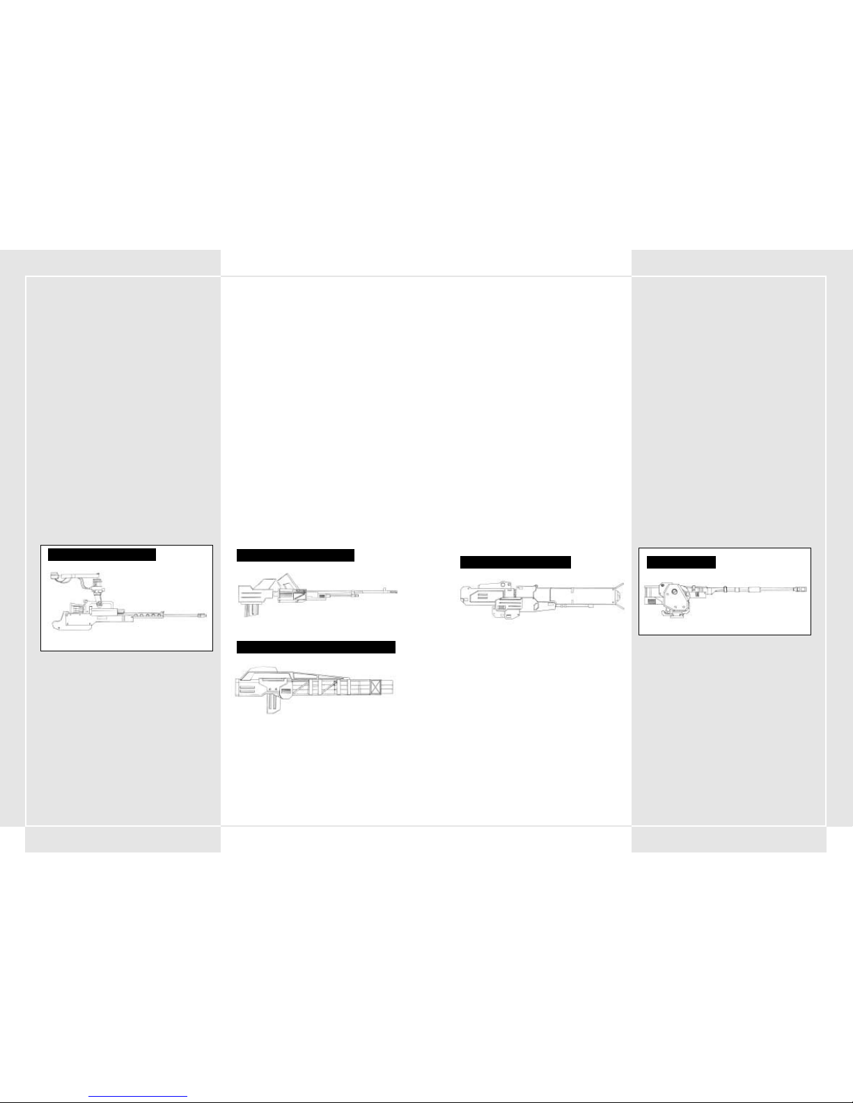
117116
SQUALL: MORTERO ANTI-VT GUIADO
Es la única arma anti-VT de ángulo elevado que tiene capacidad
de buscador (dirigirse al blanco).
RAILGUN A
Es el arma más reciente de las desarrolladas por PRF. Mediante
un pulso electromagnético, esta arma dispara su munición
a hipervelocidad. Su alcance de ataque y su potencia de fuego no
tienen precedentes.
RAILGUN B
Arma desarrollada por Hai Shi Dao. Mediante un pulso
electromagnético, esta arma dispara su munición a
hipervelocidad. Su alcance de ataque y su potencia de fuego no
tienen precedentes.
LANZADOR HVM
Esta arma dispara munición perforante reactopropulsada.
Aunque su alcance y potencia de fuego son de la clase más alta,
no está equipada con sistema buscador.
OBÚS de 225 mm
Esta arma dispara proyectiles en trayectoria de arco elevado.
Aunque no es demasiado destructiva, es capaz de infligir daños
en un radio fijo tras el impacto. Es muy eficaz contra áreas
pobladas de AFV.
OBÚS de 305 mm
Esta arma dispara proyectiles en trayectoria de arco elevado.
Aunque no es demasiado destructiva, es capaz de infligir daños
en un radio fijo tras el impacto. Es muy eficaz frente a áreas
pobladas de AFV.
OBÚS de 370 mm
Esta arma dispara proyectiles en trayectoria de arco elevado. Es
capaz de infligir daños en un radio fijo tras el impacto.
Dependiendo de su uso, puede ser muy eficaz.
OBÚS de 550 mm
Esta arma dispara proyectiles en trayectoria de arco elevado. Es
muy destructiva y capaz de infligir tremendos daños en un radio
fijo tras el impacto.
MLRS DE CAPACIDAD 8 (Sistema lanzacohetes
múltiple)
Este MLRS con capacidad de 8 disparos sucesivos lanza grandes
cohetes con trayectorias de ángulo elevado. Es capaz de infligir
daños con su gran radio de explosión. Es muy efectiva si se desea
despejar un área grande de terreno.
FUSIL DE ÁNIMA LISA de 355 mm
Esta arma dispara munición APFSDS de baja trayectoria.
Comparado con el rifle, tiene un mayor alcance de tiro.
FUSIL DE ÁNIMA LISA de 430 mm
Es la mayor arma de su clase. Sus especificaciones de poder
destructivo y de alcance de tiro son más que satisfactorias.
AMETRALLADORA de 67 mm
Esta arma tiene una enorme capacidad de disparo rápido de
munición perforante pequeña. Como su potencia de fuego es
relativamente pequeña, es un arma ineficaz frente a los VT. Sin
embargo, es muy eficaz frente a los AFV y los helicópteros de
asalto.
AMETRALLADORA de 80 mm
Esta arma tiene una capacidad muy grande de disparo rápido
y dispara pequeña munición perforante. Como su potencia de
fuego es relativamente pequeña, es un arma ineficaz frente a los
VT. Sin embargo, es muy eficaz frente a los AFV y los helicópteros
de asalto.
AMETRALLADORA de 100 mm
Esta arma tiene una capacidad muy grande de disparo rápido
y dispara pequeña munición perforante. Como su potencia de
fuego es relativamente pequeña, es un arma ineficaz frente a los
VT. Sin embargo, es muy eficaz frente a los AFV y los helicópteros
de asalto.
AMETRALLADORA PESADA de 120 mm
Es una arma más destructiva que la ametralladora. Aunque tiene
una gran capacidad de disparo rápido, no es tan efectiva como
las armas anti-VT. Sin embargo, es muy efectiva frente a los
cañones móviles de apoyo.
AMETRALLADORA PESADA de 140 mm
Es una arma más destructiva que la ametralladora. Aunque tiene
una gran capacidad de disparo rápido, no es tan efectiva como
las armas anti-VT. Sin embargo, es muy efectiva frente a los
cañones móviles de apoyo.
AMETRALLADORA PESADA de 135 mm
Es una ametralladora pesada que se coloca bajo el cuerpo
principal del VT. Es más potente que la ametralladora normal de
cadena y su característica de disparo rápido agregada la
convierte en un buen arsenal secundario.
CAÑÓN DE COHETES TIERRA-TIERRA MK21
Esta arma puede disparar seis cohetes tierra-tierra de tamaño
medio simultáneamente.
CAÑON DE COHETES TIERRA-TIERRA MK34
Esta arma puede disparar simultáneamente cuatro cohetes tierratierra y es una amenaza letal para cualquier VT.
RAIL GUN (CAÑÓN DE PULSOS)
OBÚS de 370 mm
AMETRALLADORA de 67 mm
CAÑON AUTOMÁTICO de 120 mm
CAÑÓN DE COHETES TIERRA-TIERRA MK21
Page 61

119118
LANZALLAMAS
Es un arma para combate cercano que se coloca debajo del
cuerpo principal del VT. Un impacto directo con esta arma hará
que un VT se incendie.
BARRA ELÉCTRICA
Diseñada especialmente para combate cercano con los VT, un
impacto directo con esta arma causará una descarga masiva de
voltios de electricidad que incapacitará al VT enemigo
temporalmente.
BOMBA CORTADORA
Esta gran bomba cortadora se adapta al VT para el combate
cercano. Es el arma más destructiva en combate cercano.
GRANADA DE DETONACIÓN CRONOMETRADA
ÁREA
Esta granada está diseñada especialmente para el combate
cercano. Debido a las espoletas de contacto internas, la granada
detonará e infligirá daños incluso sin contacto directo con el
objetivo.
GRANADA DE DETONACIÓN CRONOMETRADA
AÉREA CON CAPACIDAD DE 3 PROYECTILES
Esta granada está diseñada especialmente para el combate
cercano. Debido a las espoletas de contacto internas, la granada
detonará e infligirá daños incluso sin contacto directo con el
objetivo.
CARGADOR DE HUMO
Esta arma dispara cuatro granadas de humo. Su único propósito
es crear humo denso para cegar la visibilidad del enemigo e
impedir su capacidad de ataque.
MINA PROYECTIL ANTI-VT
Esta arma es capaz de descargar simultáneamente tres minas antiVT que se proyectan hacia adelante.
DEPÓSITO PROPELENTE
Es un depósito de combustible del VT. Después de vaciar el
depósito puede desprenderse para aligerar la carga.
BLINDAJE ADICIONAL
El blindaje adicional permite aumentar la vida del VT. También le
otorga al piloto la posibilidad de utilizar los misiles guiados que
hay cargados dentro del receptáculo del blindaje. Presione F1
durante el combate para liberarlos.
SUMINISTROS DE REPUESTO
Los suministros de repuesto incluyen munición y combustible. Se
entregará un suministro de repuesto cuando se solicite un
helicóptero de suministros.
RADIOCASETE
Esta radiocasete antigua se descubrió en el área de
almacenamiento del campo de instrucción. Póngala en la cabina
para escuchar algunas canciones durante el combate.
MLRS DE CAPACIDAD 12
Este MLRS con capacidad de 12 disparos sucesivos lanza grandes
cohetes con trayectorias de ángulo elevado. Es capaz de infligir
daños con su gran radio de explosión. Es muy eficaz si se desea
conquistar un área grande de terreno.
LANZAMISILES COMPACTO DE DOBLE
RECEPTÁCULO
Es un lanzamisiles doble compacto que se coloca bajo el cuerpo
central del VT.
LANZAMISILES COMPACTO DE TRIPLE
RECEPTÁCULO
Es un lanzamisiles triple compacto que se coloca bajo el cuerpo
central del VT.
MISIL GUIADO ANTI-VT ASLAM (Misil avanzado de
ataque guiado tierra-tierra a distancia)
Misil guiado por infrarrojos del tipo “dispara y olvídate”. En
función de la programación de las pautas de movimiento del VT,
su precisión de localización del objetivo mejora, lo que se
traduce en un número extremadamente alto de impactos
directos.
POZIT: MISIL GUIADO ANTI-VT
Misil guiado por infrarrojos del tipo “dispara y olvídate”. Aunque
inferior que el ASLAM, es un misil preciso y destructivo.
MISIL GUIADO COMPACTO DE DOBLE CARGA
Es un lanzamisiles doble compacto guiado que se coloca bajo el
cuerpo central del VT. Aunque su rendimiento no es elevado, está
equipado con un sistema buscador.
MISIL GUIADO AVTDV
Es un misil anti-VT grande, también conocido como "Mata VTs”.
Es el misil más mortífero, debido a su avanzado sistema de guía,
largo alcance de tiro y fuerza destructora.
DISPERSOR ALC205
Diseñada especialmente para el combate cercano con VT, esta
arma es muy destructiva y tiene la ventaja de poder abatir a un
enemigo con un impacto directo.
DISPERSOR ALC22B
Diseñada especialmente para el combate cercano con VT, esta
arma es muy destructiva y tiene la ventaja de poder abatir a un
enemigo con un impacto directo.
NAPALM
La munición de napalm se puede cargar en cualquier lanzador
compacto que se coloque bajo el cuerpo principal del VT. El
napalm es muy eficaz para arrasar enemigos terrestres por su
capacidad natural para incendiar un área de tierra determinada.
Un VT se incendiará con un impacto directo de napalm.
DISPERSOR ALC205
MISIL GUIADO ANTI-VT
GRANADA DE DETONACIÓN
CRONOMETRADA AÉREA
Page 62

121120
2-11 ALCANCE DE TIRO DEL ARMAMENTO CON
TRAYECTORIA CURVA EN EL MAPA DE GUERRA
Debe bloquear el objetivo de antemano si utiliza un arma con
trayectoria de disparo curva. Al elegir un arma con trayectoria de
disparo curva, el objetivo, dirección de tiro y lugar de impacto
del arma aparecerán en una línea blanca en el Mapa de guerra.
Puede utilizar esta información para intentar acertar al enemigo
incluso cuando no haya bloqueado el objetivo.
2-12 ESPOLETA CORTA
Se ha colocado una espoleta corta en la munición del cañón sin
retroceso Ak19-77 y en las granadas de corto alcance (se utilizará
regularmente una espoleta corta para la artillería normal). Las
espoletas cortas utilizan el magnetismo para buscar sus objetivos
y hacen explosión cuando están a una distancia establecida.
Gracias a ello, no es necesario hacer impacto directo en el
objetivo para dañarlo. En una batalla de VT, que son móviles y
rápidos, esas espoletas cortas pueden desempeñar una
importante función de apoyo para dañar al oponente.
2-13 DEFENSA ANTIRRADAR
Para defenderse frente a misiles guiados por radar, el VT ha sido
equipado con una unidad que suelta tamo (partículas de metal
que perturban las señales de radar). El tamo estalla en cuatro
direcciones distintas cuando se ha disparado un misil al VT.
Estallan pedazos de aluminio en el aire y el misil guiado bloquea
el tamo como objetivo, abandonando el VT.
Si se desplaza lateralmente después de lanzar el tamo, puede
esquivar más eficazmente el misil.
3-1 ADICIONES AL COOS DE 2ª GENERACIÓN
Actualmente, el COOS que dirige todos los movimientos del VT ha
cambiado a la 2ª generación y ha aumentado la funcionalidad de
las capacidades del VT. Junto a un aumento en la potencia del
procesador, COOS dispone de nuevo armamento guiado anti-VT y
de un útil sistema de disparo por estimación del objetivo (FSS).
Esas nuevas adiciones le proporcionan al VT incluso más poder
destructivo. A continuación hay una lista de muchas de las
funciones del COOS de 2ª generación.
3-2 FUNCIÓN FSS (Sistema de disparo por
estimación del objetivo)
FSS analiza el patrón de movimiento del VT objetivo, la distancia
de recorrido de la bala y la cantidad de tiempo que el proyectil
estará en el aire. Después, mueve automáticamente el buscador
de objetivos hasta la siguiente ubicación probable del enemigo.
Para cambiar el modo de puntería FSS a "puntería directa"
presione el botón FSS. Consulte la sección 5-4 para obtener más
información acerca de FSS.
3-3 FUNCIÓN OVERDRIVE (SUPERDIRECTA)
Esta función se utiliza para proporcionarle al VT un aumento de
velocidad durante un tiempo limitado. Desactiva el "limitador de
velocidad", que protege a diversas juntas del desgaste. Para
obtener más información acerca de la función superdirecta,
consulte la sección 4-6.
3-4 FUNCIÓN STEALTH (SIGILO)
Función sigilosa incluida en el VT que le permite evadir la
detección por radar. Se consigue utilizando pintura absorbente
de emisiones de radar, mejorando los tubos de emisión de gases
y haciendo más aerodinámico el casco principal.
3-5 ARMAS GUIADAS
Una de las principales características nuevas del COOS de
2ªageneración es el mayor uso de armas guiadas. Se han agregado
nuevos misiles guiados anti-VT al sistema ya establecido de guía
activada por láser. El sistema analiza los patrones de movimiento
del VT y predice la siguiente ubicación del enemigo mediante FSS
en tiempo real, lo que aumenta la precisión de tiro. Se espera
que el nuevo sistema sea muy eficaz en batallas anti-VT.
SECCIÓN 3. FUNCIONES
ESPECIALES HASTA LA 2ª
GENERACIÓN DEL COOS
TRAYECTORIA CURVA FRENTE A TRAYECTORIA RECTA
Trayectoria curva
Trayectoria recta
4-1 SECUENCIA DE INICIO
Al entrar en un VT antes de moverlo al frente, la batería del VT,
su depósito de combustible y el armamento están al máximo de
capacidad. La secuencia de inicio se describe a continuación.
1. Cierre la escotilla de la cabina
Presione el botón Cockpit Hatch (Escotilla de cabina)
situado en el lado derecho. Compruebe si la escotilla de la
cabina está abierta o cerrada.
2. Presione el botón Ignition (Ignición)
Presione el botón Ignition (Ignición) situado bajo el botón
Cockpit Hatch (Escotilla de cabina). Arrancará el motor y
se suministrará energía a la cabina desde el generador. El SO
del VT se conecta y muestra de forma automática en la
pantalla una comprobación sencilla de las funciones, antes
de que aparezca la pantalla Startup Function (Función de
inicio).
3. Funciones de inicio
Cuando aparezca la comprobación de funciones, debe
activar cada una de las siguientes funciones para comprobar
si son operativas. Desplácelas hacia arriba una por una con
el dedo índice para encenderlas.
•Oxygen Supply System (OSS) (Sistema de suministro de
oxígeno): suministra oxígeno respirable y estable dentro
de la cabina.
• Filter Control System (FCS) (Sistema de control de
filtro): conmutador que enciende el sistema de
eliminación de gases de combustión. Elimina gases de
combustión y estabiliza el motor.
• VT-Location Measurement (VT-LM) (Cálculo de
ubicación del VT): sistema de estimación de localización
de la unidad. Función utilizada para mostrar
automáticamente su VT en el Mapa de guerra.
• Buffer Material (BM) (Material de amortiguación):
sistema que exuda un material protector alrededor de la
cabina para protegerla frente a ataques. Recubre la cabina
y el área frontal del cuerpo principal del VT con un gel
duro para la protección.
•Fuel Flow Rate (FFR) (Velocidad de flujo de
combustible): sistema que regula el flujo de combustible.
Controla el flujo de combustible y dispersa la cantidad
correcta de combustible en función de la condición actual
del motor.
4. Presione el botón Start (Inicio)
Una vez completada la secuencia de arranque inicial, se
muestra una imagen del exterior circundante. Después se
suministra energía a las diversas juntas del VT mediante un
activador. Después de que los distintos sistemas hayan
cruzado la línea de estabilización, presione el botón Start
(Inicio). Cuando haya completado las diferentes funciones,
el VT debe bloquearse en el modo de inicio y podrá
comenzar a controlarlo.
4-2 CUANDO SE PARA EL VT DURANTE EL INICIO
Si presiona el botón Start (Inicio) cuando NO todos los sistemas
han cruzado la línea de estabilidad ocasionará que varias piezas
de juntura cesen el bloqueo, cancelen la secuencia de inicio y
paren el VT. Se ha diseñado así para proteger al VT de los daños
que pudieran derivarse de superar el límite del VT Si se para el
VT durante el inicio, relájese y espere a que los diferentes
calibradores del sistema se vuelvan a encender. A continuación,
vuelva a intentar arrancar la máquina presionando de nuevo del
botón Start (Inicio).
SECCIÓN 4. CONTROLES DEL VT
PANTALLA STARTUP (INICIO)
Stabilization Line
(Línea de estabilización)
PRIMARY SYSTEMS STATUS CHECK (COMPROBACIÓN DEL
ESTADO DE LOS SISTEMAS PRINCIPALES)
Page 63

123122
CONTROLES BÁSICOS
4-3 MOVERSE Y DETENERSE
Moverse y detenerse son los dos movimientos más básicos del VT.
Puede cambiar la palanca de cambios de 1ª a 5ª velocidad. Si se
presiona el acelerador aumentan las RPM del motor y el VT se
mueve hacia adelante. Puede poner la palanca de cambios
marcha atrás para moverse hacia atrás. El VT se detiene si quita
el pie del acelerador y pisa a fondo el pedal de freno. Si realiza
giros cerrados al moverse a altas velocidades, el VT puede volcar,
por lo que debe ser cuidadoso.
4-4 ACELERACIÓN Y DESACELERACIÓN
La medida de aceleración y desaceleración depende de la
cantidad de presión que se aplique al acelerador. Se frena al
presionar el pedal de freno o al reducir la marcha en la palanca
de cambio. En punto muerto, el VT estará a 0 mph (km/h). Con
cada nivel de marcha ganará velocidad, pero perderá par motor.
En áreas en las que la velocidad no aumente suavemente es
conveniente reducir la marcha para mejorar la eficacia de
combustión. Poner la palanca de cambios marcha atrás hace que
el VT vaya marcha atrás.
4-5 ROTACIÓN
La rotación del VT se efectúa al presionar el controlador de
rotación izquierdo
o La velocidad de rotación aumenta en
función de la cantidad de presión que se ejerce en la palanca de
rotación en cualquier dirección. Si el nivelador no puede
mantener el equilibrio total del VT, éste puede volcar, por lo que
debe ser cuidadoso.
4-6 OVERDRIVE (SUPERDIRECTA)
Esta función se desarrolló después de que varios pilotos expertos
la solicitaran. Deshabilita el limitador de velocidad que protege
a varias juntas del desgaste, lo que resulta en un aumento de
velocidad. El bloqueo del limitador se desactiva al presionar el
botón Overdrive (Superdirecta). Si se presiona de nuevo el
botón Overdrive (Superdirecta) se vuelve a reactivar el bloqueo.
Cuando el VT está en marcha superdirecta, se triplica el consumo
de combustible respecto al funcionamiento normal, de modo que
debe ser cuidadoso al utilizarlo.
4-7 FUNCIÓN SLIDESTEP (DESLIZAMIENTO)
Es una de las formas especiales del VT para esquivar la potencia
de fuego lanzada contra él. Es una de las diferencias importantes
entre el VT y un tanque normal. Puede moverse rápidamente a
izquierda o derecha utilizando la programación del SO. También
puede utilizar esta función para recuperar rápidamente el
equilibrio en caso de que el VT esté a punto de volcar. El
deslizamiento se utiliza como movimiento rápido en una de las
cuatro direcciones, mediante rutas previamente programadas. Es
llevado a cabo por una combinación de aceleración y de uso del
nivelador. El nivelador refuerza automáticamente las juntas o
áreas que se verán más afectadas por el desgaste. El
deslizamiento se realiza al presionar la palanca de rotación
o ^ , mientras se presiona simultáneamente el pedal de
deslizamiento. El deslizamiento es un buen método para
esquivar un ataque del enemigo. Se puede conseguir otro
movimiento dejando la palanca de rotación en punto muerto y
presionando el pedal de deslizamiento. Así el VT hará un
desplazamiento rápido hacia adelante. Si ejecuta esta función
con la marcha atrás, producirá un desplazamiento rápido hacia
atrás.
4-8 LIMITACIONES FUNCIONALES DEL
DESLIZAMIENTO
Realizar un deslizamiento provoca una gran tensión en las
secciones de juntas del VT. Para disminuir el desgaste, se utiliza
una gran cantidad de energía a través del activador. La energía
originada en el generador se recicla para mantener la batería
principal, pero disminuye en gran medida la carga de la batería
cada vez que se realiza un deslizamiento. En los casos en los que
no hay suficiente energía, se cancela automáticamente el
deslizamiento. Cuando la batería está baja de carga, aparece una
advertencia de calentamiento. No utilice el deslizamiento cuando
aparece esa advertencia.
4-9 REGULADOR DE INCLINACIÓN DE
DESLIZAMIENTO
Siempre que el movimiento del VT excede el límite del nivelador,
existe la posibilidad de que vuelque. El desequilibrio se produce
por el funcionamiento imprudente o por giros pronunciados a
altas velocidades. También puede ocurrir cuando recibe un
impacto del enemigo. Siempre que parezca probable que se va a
producir un desequilibrio, presionar el pedal de deslizamiento
volverá a equilibrar el VT. Sin embargo, si la batería del VT tiene
poca carga, será incapaz de realizar esta maniobra. Si vuelca,
libere el acelerador y vuelva a presionarlo para levantar de
nuevo el VT.
4-10 FUNCIÓN CUT-OFF (DESCONEXIÓN)
En casos en los que sufra daños que excedan la capacidad
máxima de daño, el VT se apagará automáticamente
(desconexión) para proteger a varias secciones de junta de daños
adicionales. Cuando se produce una desconexión, todos los
bloqueos se anulan y el VT se para. Entonces debe ejecutar
rápidamente la secuencia de inicio de nuevo para volver a
encender el VT.
FUNCIÓN SLIDESTEP (DESLIZAMIENTO)
4-11 CONTROLES DEL MANIPULADOR
En el VT, un manipulador controla un brazo capaz de abrir y cerrar
puertas, y de mover el cargamento. Está adherido al lazo izquierdo
del casco principal. Si presiona el botón del manipulador, lo
activará. Si centra el manipulador en un objetivo y presiona el
botón de arma secundaria puede recoger el objeto. Ya que debe
presionar el botón de arma secundaria para utilizar el
manipulador, no puede utilizar ningún arma secundaria durante
este tiempo.
USO DEL MANIPULADOR PARA
CONTROLAR UN ASCENSOR
USO DEL MANIPULADOR PARA ABRIR
Y CERRAR PUERTAS DE CARGA
MANIPULADOR
RECUPERAR ELEMENTOS CON EL
MANIPULADOR
Puntería normal con armas secundarias
Puntería en el modo manipulador
Page 64

125124
PANTALLA DEL VT
4-12 CAMBIO DE LA CÁMARA PRINCIPAL
La perspectiva del VT está determinada por la cámara principal.
La imagen se muestra en la cabina. La cámara enfoca
normalmente al frente y al centro. Si se presiona el botón de la
palanca de pilotaje izquierda
,
, o ^^ puede aumentar la
superficie de área visible. Si presiona el botón de la palanca de
control puede volver a centrar la vista directamente delante del
VT. Al utilizar eso y la pantalla secundaria del VT (descrita
posteriormente), podrá mover el VT mejorando su utilidad en
combate.
4-13 POLVO Y SUCIEDAD EN LA CÁMARA
PRINCIPAL
En combate, debe disponer de una visión clara en la pantalla
principal. En el caso de que la pantalla aparezca gris, con polvo
o suciedad, presione el botón de lavado para limpiarla.
PERSPECTIVAS DE CÁMARA
4-14 FUNCIONES DE LA PANTALLA SECUNDARIA
Si presiona el botón de selección de modo de la pantalla
secundaria bajo la pantalla principal, puede cambiar entre cuatro
modos.
• Modo de vista frontal
Muestra lo que hay directamente frente al VT. Utilice esta
vista con la función de cambio de sitio para ver las cosas con
más claridad.
• Modo de vista posterior
Muestra lo que hay directamente detrás del VT. Como en la
vista frontal, si utiliza esta vista con la función de cambio de
sitio puede ver las cosas con más claridad.
• Modo de vista de bloqueo de objetivo
Utilizado para acercar el objetivo bloqueado. Un objetivo
que esté muy lejos aparecerá en la pantalla secundaria
incluso sin acercarlo.
• Modo de vista aérea (vista de pájaro)
Esta vista muestra el VT desde 50 metros por encima de él.
Es útil para ver puntos ciegos y mirar alrededor de objetos.
4-15 EQUIPO DE VISIÓN NOCTURNA
Se ha incluido un catalejo de visión nocturna en el VT para
utilizarlo bajo condiciones de poca luz, como de noche o en
entornos llenos de humo. Para utilizar el catalejo, presione el
botón night scope (catalejo nocturno) . El VT utiliza el JGVSV442 de tipo pasivo, que proyecta luz infrarroja a un sujeto y lo
muestra en formato gráfico en la pantalla. El catalejo de visión
nocturna se puede utilizar no sólo en la oscuridad y en áreas con
mucho humo, sino también para ayudar a detectar objetivos
camuflados. El catalejo divisa hasta una distancia de unos 2,5
kilómetros y la visualización se muestra en la pantalla normal.
Cuando se utiliza el catalejo en la oscuridad, los fogonazos de la
batalla o de una granada oscurecerán el catalejo temporalmente
y no podrá ver.
JCS (Sistema de mando completo)
4-16 RESUMEN DE JCS
JCS es un sistema que utiliza datos de estrategia de guerra y la
información más reciente para aumentar la eficacia del VT al
máximo. Su propósito principal es suministrar la información más
reciente respecto al campo de batalla, a las fuerzas aliadas, al
enemigo y a otras compañías y batallones. El sistema está
diseñado para aumentar la eficacia global del VT en combate. Los
pilotos de VT así como los jefes de pelotón deben ser capaces de
utilizarlo eficazmente.
JCS utiliza una red que va desde el puesto de mando de
transporte de los VT hasta los puestos de mando de las distintas
compañías y batallones, lo que ayuda a llevar las noticias más
recientes hacia y desde las personas apropiadas. Este sistema
envía mensajes desde las pantallas de vídeo del VT, satélites de
reconocimiento y otras divisiones de mando y edita los datos en
tiempo real en los puestos de mando del batallón. Después
analiza los datos y los envía a los distintos pelotones. Los
diferentes datos se envían al VT a través de una red de
comunicaciones y se muestran en las diversas pantallas de la
cabina. Gracias a este sistema, los pilotos pueden consultar el
mapa y las ubicaciones del enemigo, y administrar el fuego de
apoyo a sus fuerzas.
GRÁFICO RESUMEN DE LAS REDES DEL
SISTEMA DE MANDO COMPLETO
Centro de mando de transporte de VT
VT
Avión de reconocimiento
Satélite de reconocimiento
Page 65

127126
4-17 PANTALLA MÚLTIPLE
La pantalla múltiple del área superior del monitor principal se
utiliza para mostrar información enviada desde el Centro de
mando superior. La pantalla múltiple no está siempre visible.
Puede activar y desactivar su visualización si presiona el botón
de abrir y cerrar de la pantalla múltiple.
4-18 INFORMACIÓN MOSTRADA EN LA
PANTALLA MÚLTIPLE
En la pantalla múltiple se muestra la siguiente información.
1. Mapa de guerra
Muestra un radio de 25 kilómetros del área circundante.
Utilice el zoom para alejar o acercar el mapa hasta un
máximo de 5.000 km de radio.
2. Información personal del VT
Muestra el estado y las estadísticas actuales del VT. Utilícelo
para comprobar el blindaje o combustible de reserva del que
dispone.
3. Objetivo de la misión
Muestra información relativa al objetivo principal de la
misión actual. Si hay un cambio repentino en la misión, esa
información aparece aquí. Los pilotos y los jefes de
pelotones especiales deben asegurarse de comprobarlo.
4. Pelotón
Sólo muestra los datos del mando del pelotón. Puede
consultar las órdenes actuales para los otros miembros de
ese pelotón.
5. Información del enemigo
Muestra información acerca de los VT del enemigo: la
distancia de tiro de sus armas, poder de ataque, etc.
También muestra datos sobre varias máquinas de apoyo.
VT amigos
VT
Otros elementos de tierra (tanques, cañones)
Fuerzas áreas (helicóptero, bombarderos)
Zona de impacto estimada para un arma de
trayectoria curva
Balas
Área de impacto estimada para el arma principal
Área de impacto estimada para el arma secundaria
PANTALLA DE MAPAS
PANTALLA MÚLTIPLE
COMPROBAR EL NÚMERO DE ENEMIGOS DESTRUIDOS
Número y tipo de enemigos destruidos
Número total de enemigos destruidos
Objetivo principal
Orden respecto al objetivo principal
PANTALLA DE OBJETIVO PRINCIPAL
Orden que el hombre de flanco 1 está
llevando a cabo
Orden que el hombre de flanco 2 está
llevando a cabo
ESTADO DEL HOMBRE DE FLANCO
Depósito de combustible 1
Depósito de combustible 2
Blindaje complementario
Número restante de puntos con
blindaje adicional
ESTADO PARTICULAR DEL VT
PROCEDIMIENTOS DE EMERGENCIA
4-19 CONFIGURACIÓN DE LA EVACUACIÓN
Se ha agregado una característica de evacuación al VT para proteger
la seguridad del piloto. Si sufre daños continuamente, si el blindaje
de resistencia está mermado (ver la sección 2-5) o si el VT alcanza
niveles peligrosos, protéjase a sí mismo utilizando el sistema de
eyección lo antes posible. La capa de gel protector que rodea la
cabina se convertirá en el receptáculo de fuga y un pequeño cohete
colocado bajo el receptáculo le lanzará al exterior.
4-20 INTERRUPTOR DEL EYECTOR DE
EMERGENCIA
El interruptor del eyector de emergencia se encuentra en el lado
derecho de la consola. Está rodeado por una cubierta de cristal negra
y amarilla.
El interruptor está en el mismo lado que el botón Start (Inicio), por
lo que debe asegurarse de no presionarlo accidentalmente. Al
presionar el interruptor, se dispara la cabina por detrás del VT. La
capa del bloque de gel forma una bolsa de aire (air bag) alrededor de
la cabina por todos los lados para protegerle del choque del
aterrizaje.
4-21 PROCEDIMIENTOS DE ESCAPE DE
EMERGENCIA EN RÍOS O MARES
Como el VT no es 100% estanco e impermeable, no puede navegar en
masas de agua en una profundidad superior a los 20 metros y en esa
situación no podrá moverse. Si cae en aguas de profundidad superior
a los 20 metros, el agua empezará a filtrarse a través de la cabina
recubierta de gel, obligándole a utilizar el sistema de eyección. El uso
del sistema de eyección es el mismo en el agua que en tierra. La capa
de gel formará una bolsa de aire (air bag) elevándole a la superficie.
4-22 INCENDIO EN EL CASCO
Siempre que se declare un incendio en el casco, debe actuar
rápidamente. Los daños producidos por lanzallamas y por sufrir
demasiados impactos pueden iniciar un fuego que dañará la coraza
y debilitará el blindaje del VT. Si las luces de advertencia de incendio
en interior se apagan y las luces de advertencia de la cabina
parpadean, compruebe en qué área está el fuego y presione el botón
del extintor de incendios en el panel de control.
INTERRUPTOR DEL EYECTOR DE EMERGENCIA
PROCEDIMIENTO DE EYECCIÓN DEL PILOTO
EL BLINDAJE DE RESITENCIA VA A ALCANZAR
LA MASA CRÍTICA
Page 66
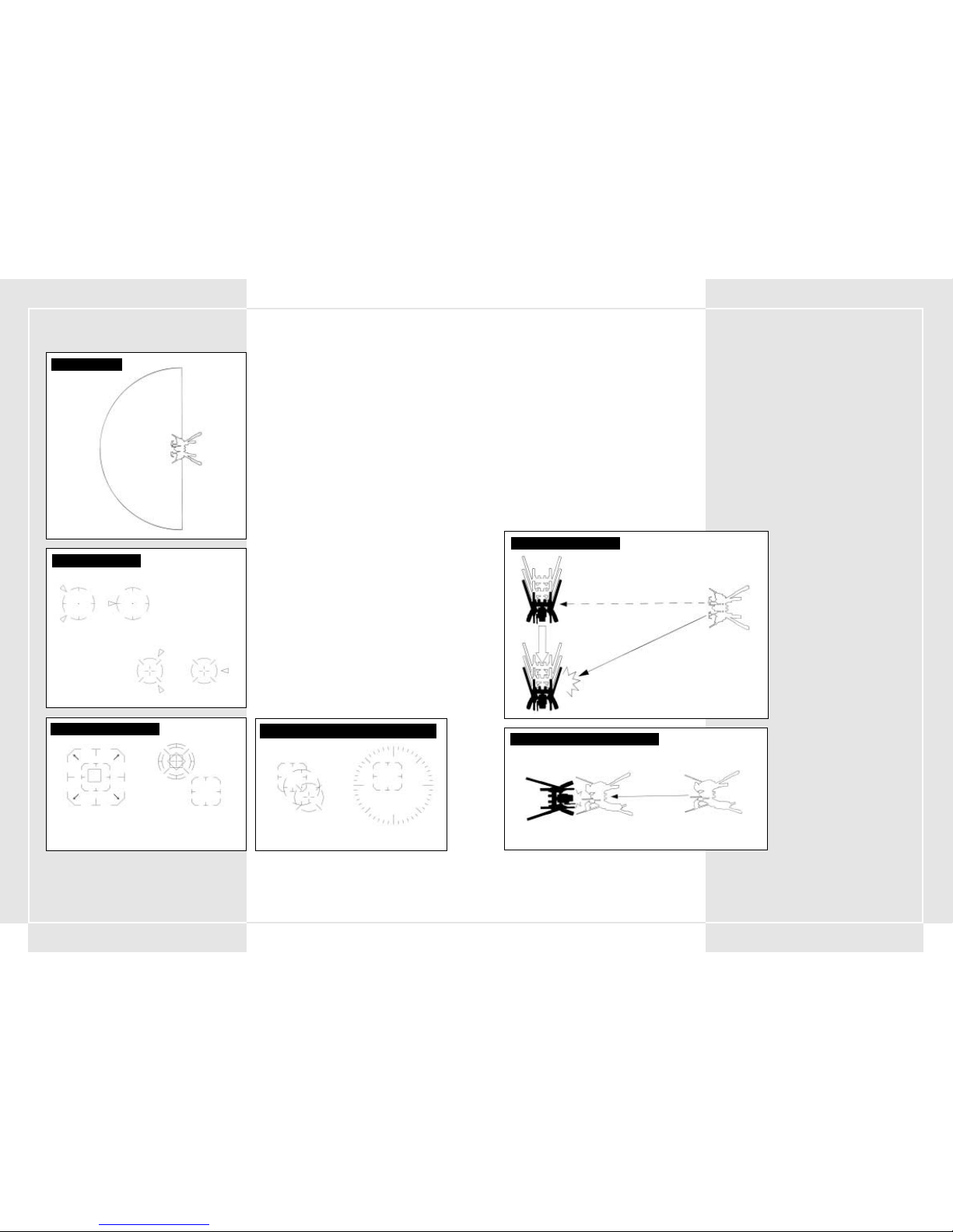
129128
5-1 APUNTAR Y DISPARAR CON ARMAS
La puntería con armas se realiza utilizando la palanca de
puntería derecha para colocar el punto de mira sobre el
enemigo en la pantalla. El armamento del cuerpo superior es
capaz de moverse independientemente, por lo que el VT tiene un
máximo de 180˚º de radio de tiro. Después de colocar el cursor
sobre el enemigo, puede disparar el arma principal si presiona
el disparador de arma principal o el arma secundaria si
presiona el disparador ésta.
5-2 FUNCIÓN LOCK-ON (BLOQUEO DE
OBJETIVO)
En el VT, una característica de bloqueo de objetivo especial
apunta automáticamente a determinados enemigos. Cuando el
punto de mira empieza a parpadear en la pantalla, si presiona el
botón de bloqueo de objetivo en la palanca de puntería
derecha podrá bloquearlo. Mientras esté bloqueado, si presiona
el disparador del arma principal o el del arma secundaria
disparará automáticamente al enemigo. Puede desbloquear el
objetivo, presionando de nuevo el botón de bloqueo de
objetivo, cuando el enemigo ha sido destruido o si éste consigue
deslizarse fuera de la pantalla.
Nota: debido a que la función de bloqueo de objetivo se diseñó
básicamente para el uso anti-VT, cualquier otro objetivo que no
sea un VT o cañones del enemigo no funcionará con la
característica de bloqueo de objetivo.
5-3 PUNTERÍA EN COMBATE CERCANO
El armamento secundario del VT incluye varias armas para
combate cercano. El dispersor ALC205 es un buen ejemplo, ya
que sólo puede utilizarse en un VT y es un arma bastante
especial. No obstante, debe ser cuidadoso. Si utiliza una de esas
armas, el objetivo será ligeramente distinto del normal y
cambiará al modo de combate cercano. Este modo de tiro es útil
para la lucha cercana con un enemigo rápido que está
inmediatamente frente a usted. El punto de mira sólo funcionará
en elementos situados frente al VT. Si presiona el botón de arma
secundaria mientras el enemigo está justo frente a usted,
cargará hacia adelante y golpeará con el dispersor.
SECCIÓN 5. ATAQUE DEL VT
BLOQUEO DEL OBJETIVO
RADIO DE TIRO
DISTANCIA DE TIRO
180
°
TIRO CON ARMA SECUNDARIA
Fuera de alcance de tiro Dentro del alcance de tiro
TIRO CON ARMA PRINCIPAL
Fuera de alcance de tiro Dentro del alcance de tiro
Bloqueo de objetivo posible Después del bloqueo
CURSORES EN COMBATE NORMAL Y CERCANO
Modo normal Modo cercano
5-4 FSS (Sistema de disparo por estimación del
objetivo)
El FSS es un sistema de disparo desarrollado para analizar datos
de combate y pautas de movimiento de VT enemigos
Si se presiona el botón FSS en la palanca de puntería, cambiará
el modo de disparo de normal a sistema de disparo por
estimación del objetivo, lo que permite centrarse en la siguiente
ubicación probable del enemigo. Si presiona de nuevo el botón
FSS volverá al modo de disparo normal.
Nota: FSS es una nueva función del SO de 2aª generación y por lo
tanto no está incluida en los VT con SO de primera generación.
Los datos de estimación sobre la pauta de movimiento del
enemigo no son perfectos y si el oponente está bien entrenado
puede realizar movimientos que el FSS es incapaz de estimar. De
manera que el FSS no será eficaz en algunos oponentes.
5-5 ALCANCES DE TIRO DE DIFERENTES ARMAS
Cada arma tiene su alcance de tiro. El piloto debe tener un
profundo conocimiento del alcance máximo de tiro y del alcance
más eficaz de cada arma. El alcance de tiro eficaz de cada arma
aparece a la izquierda o derecha del objetivo de la pantalla
principal y lo establece el sistema de control de artillería.
El alcance de tiro principal del arma aparece a la derecha del
punto de mira. El alcance de tiro principal del arma secundaria
aparece a la izquierda. El alcance de tiro principal de ambas
armas se superpone con el punto de mira. Si el enemigo sale
fuera del alcance, aparece un mensaje que se lo indica.
5-6 NOTAS ACERCA DEL DISPARO CON ALCANCE
DE TIRO EFICAZ
El alcance de tiro eficaz se configuró principalmente para
mostrar el alcance de tiro eficaz en la pantalla principal. No
obstante, se diseñó básicamente para el combate anti-VT. Cuando
lucha contra un oponente con menos blindaje que el VT (como un
tanque), existen bastantes posibilidades de que los disparos
tengan suficiente potencia como para eliminar algunos enemigos
que están fuera del alcance. Además, el alcance de tiro eficaz está
programado en base al grosor del blindaje del VT, como
establecen los estándares de la Organización de la costa del
Pacífico. Por lo tanto, si un objetivo con blindaje pesado está
dentro del alcance de tiro eficaz, existe la posibilidad de que no
sufra daños. Sea precavido.
CUÁNDO SE UTILIZA EL DISPERSOR
Movimiento de alta velocidad
LÍNEAS DE FUEGO DE FSS
Posición de objetivo bloqueado cuando está disparando
Posición de objetivo bloqueado cuando impacta la bala
Page 67

131130
5-7 UTILIZAR UN ALCANCE DE TIRO EFICAZ
Un aspecto muy importante de una batalla de VT es tener equipos
que hagan más daño que el enemigo y proporcionen ventaja en
combate. Especialmente cuando el alcance de tiro eficaz es
superior al del otro oponente, puede ponerse "fuera de su
alcance". Si dispone de más alcance que el enemigo, sólo
necesita aproximarse lo suficiente para disparar. Si tiene la
oportunidad de destruir al enemigo sin sufrir daños, debe utilizar
esa oportunidad al máximo. No ponga el VT, o a sí mismo, en
peligro innecesario.
5-8 ATAQUE DE TIERRA ARRASADA
Algunas armas, como el cañón de granadas, MLRS y napalm,
explotan cerca de la superficie del suelo y producen daños en el
enemigo en un radio determinado. Imponer este "fuego de
supresión" puede ser una táctica muy eficaz para eliminar
enemigos agrupados.
5-9 CAMBIO DE ARMA
Una de las áreas clave en la que los VT sobrepasan a otras
unidades es en su capacidad de montar una gran variedad de
armas diferentes. Un VT puede llevar tres armas principales y
tres armas secundarias. Sin embargo, sólo puede dispararse un
arma de cada tipo a la vez. Para elegir armas principales y
secundarias presione el botón de control de armas.
5-10 RECARGAR ARMAS CON CARGADOR
Algunas armas del arsenal utilizan cargadores. Siempre que
necesite recargar un cargador en el arma, presione el botón de
cambio de cargador. Las balas y el número de cargadores
adicionales que le queden se muestran en el panel de control.
SISTEMA DE CAMBIO DE ARMAFUEGO DE TIERRA ARRASADA
Alcance eficaz = 400 m
Alcance eficaz = 1000 m
Fuera del alcance = 1600 m
ALCANCE DE TIRO EFICAZ
(Rifle de 270 mm) (0-1500 m)
ALCANCE DE TIRO EFICAZ
(Cañón de cohetes MK34) (500-1000 m)
Alcance eficaz = 600 m
Fuera del alcance = 1600 m
Fuera del alcance = 300 m
6-1 EN GENERAL
En esta sección se explican las reglas básicas del movimiento del
VT en el campo de batalla.
El movimiento se utiliza para ocultarse de la línea de visión del
enemigo y para evitar áreas en las que pueda haber enemigos
potenciales. También debe utilizarse para evitar las áreas de
fuego enemigo concentrado. Un piloto puede suponer que el
enemigo concentrará sus VT en terrenos en los que pueda
maniobrar con ellos fácilmente, por lo que debe tenerse en
cuenta que el combate en un área en la que los VT pierdan mucho
tiempo adaptándose en realidad puede ser una ventaja.
Cuando se mueva por áreas en las que el VT pueda ser atacado
con facilidad, es posible que necesite refuerzos de la sección de
ingeniería.
6-2 UTILIZAR LA METEOROLOGÍA Y LA
TOPOGRAFÍA
En el campo de batalla, debe siempre intentar moverse con
eficacia con independencia de la meteorología y la topografía. Es
más importante hacerlo así que preocuparse por la entrada en
contacto con el enemigo.
En comparación con una máquina andante o un tanque, un VT no
se ve tan afectado por la topografía. Pero destaca por su enorme
tamaño, por lo que el enemigo lo puede localizar fácilmente.
Intente hacer buen uso de la topografía del terreno cuando esté
en una situación en la que pueda entrar en contacto con el
enemigo. Especialmente por el desarrollo de campos de energía
(ECM), cobran más importancia utilizar la topografía y tener un
buena línea de visión. En esos casos, debe concentrarse en
estimar el movimiento del enemigo y en esquivar su fuego
artillero.
• Bosque
Los bosques son lo mejor para ocultar a los VT altos.
También son obstáculos excelentes para el fuego enemigo.
• Tierra descubierta
No hay refugio donde ocultarse, por lo que lo único que
puede hacer es moverse con normalidad.
• Caminos cerrados y valles
Las rutas por las que se puede mover están limitadas a los
valles, en donde es posible que haya enemigos emboscados
esperándole. En esta zona debe ser muy precavido.
Antes de entrar en una de esas áreas, asegúrese de controlar
ambos lados. Compruebe también si hay minas enterradas en
el camino. Finalmente, tenga cuidado en las curvas del
camino y en las áreas que no es posible evitar dando un
rodeo. Sea muy cuidadoso cuando cruce un puente.
• Ríos
Por el momento las condiciones de impermeabilización
y resistencia al agua del VT están lejos de ser suficientes. En
pruebas con hasta 10 metros de agua, el movimiento del VT
fue aceptable. Sin embargo, a mayores profundidades el
agua penetra en las diversas secciones de junta y daña el VT.
A 20 metros de profundidad, el VT se avería y se para
completamente. Es esencial que examine la profundidad del
agua que va atravesar o cruzar antes de continuar.
SECCIÓN 6. MOVIMIENTO DEL VT
Page 68

133132
CONFIGURACIÓN DEL CONTROLADOR DE STEEL BATTALION
Page 69

135134
SECCIÓN 8. TRANSMISIONES DE RADIO
1. Communication panel 1 (from the main battalion Argus) begins to flash. This
signals that a message from the main battalion is coming in.
2. Set the tuner on Communications Panel 1.
3. Press Communication Button 1 (respond/call) and open a connection.
"This is Oscar 3. Argus, go ahead."
El jefe de batallón transmite su mensaje.
"This is Argus. Your division is in a bad spot! Disengage immediately!" "Aquí
Argus. Su división está en mala situación. ¡Retírese inmediatamente!"
5. After you hear what was said, press Communication Button 1 (respond/call).
"Oscar 3. I copy that."
6. Finish the communication.
7. If you didn’t hear the message, press Communication Button 2 (repeat).
PROCEDIMIENTOS DE COMUNICACIONES
(ejemplo: orden de retirada)
CABINA:
PUESTO DE MANDO DEL BATALLÓN PRINCIPAL:
1. Communication panel 1 (from the main battalion Argus) begins to flash.
This signals that a message from the main battalion is coming in.
2. Set the tuner on Communications Panel 1.
3. Press Communication Button 1 (respond/call) and open a connection.
"This is Oscar 3. Argus, go ahead."
4. The battalion head gives his message.
"This is Argus. Your division is in a bad spot! Retreat immediately!"
5. After you hear what was said, press Communication Button 1 "
6. If you didn’t hear the message, press Communication Button 2 (repeat).
7. Finish the communication.
El panel de comunicación 1 (del batallón principal Argus) empieza
a parpadear. Indica que está entrando un mensaje del batallón principal.
Ponga el sintonizador en Panel de comunicaciones 1.
Presione Botón de comunicación 1 (responder y llamar) y abra una conexión:
"This is Oscar 3. Argus, go ahead" ("Aquí Oscar 3. Argus, siga adelante").
4. The battalion head gives his message.
"This is Argus. Your division is in a bad spot! Retreat immediately!"
Después de escuchar el mensaje, presione Botón de comunicación 1 (responder y llamar).
"Oscar 3. I copy that" ("Oscar 3. Recibido").
Si no ha oído el mensaje, presione Botón de comunicación 2 (repetir).
Corte la comunicación.
8-1 RESUMEN
Las comunicaciones desempeñan una función importante: ayudar
a relacionar información clave, cambiar de plan dentro del grupo,
ayudar a cumplir órdenes importantes y facilitar la transferencia de
nuevas órdenes e información.
Para comunicarse, cada VT tiene una radio JARC-F522.
En el VT del mando del pelotón hay dos radios JARC-F522, o una
radio JARC-F522 y otra JARC-A232. Intente vocalizar claramente
cuando hable por radio y procure que la conversación sea directa y
rápida. Además, tenga cuidado con los dispositivos de escucha del
enemigo y mantenga en secreto su identidad mediante el uso de
indicativos de llamada al conversar.
8-2 CANALES PREESTABLECIDOS
En la radio estándar del VT hay algunos canales preestablecidos. Así
se ahorra el tiempo que emplearía en la sintonización de cada uno
de esos canales, tiempo del que quizá no pueda disponer en el
fragor de la batalla. Puede disponer de hasta cinco canales
preestablecidos en la radio del VT.
8-3 PROCEDIMIENTOS DE LA COMUNICACIÓN
POR RADIO
La comunicación por radio se realiza mediante la selección de
canales, utilizando una antena. Después, para empezar la
transmisión, presione el botón de comunicaciones. La
comunicación ofrece tres opciones posibles. No puede cambiar lo
que hace cada uno de esos botones de opciones. A continuación se
enumeran las opciones posibles:
• Botón de comunicación 1: para responder y llamar
• Botón de comunicación 2: repetir
• Botón de comunicación 3: solicitar suministros
7-1 ÓRDENES
Básicamente, los mandos de batallones y compañías dan órdenes
a los pelotones. Las órdenes se dan tanto oralmente como
mediante mensajes escritos. Lo más común es que antes de cada
misión haya una sesión de instrucciones, en la que se mostrará
alguna de las siguientes informaciones:
• Objetivo de la misión
• Información del enemigo
• Situación de las unidades amigas
• Topografía
• Estado del campo de batalla
• Tiempo estimado para completar la misión
Después de eso, oficiales de distinto rango ayudarán a analizar
las órdenes y el jugador establecerá un plan de ataque para su
pelotón.
7-2 ANÁLISIS DE LA MISIÓN
Cuando reciba una orden de un mando de alto rango (batallón
o compañía), el jefe del pelotón analizará la misión en función de
la información clave. El análisis de la misión incluye:
• Desglose de la misión
• Información del enemigo
• Topografía
• Armamento que puede utilizarse en la misión actual
• Equipo y suministros necesarios
Antes de que finalicen los preparativos de la estrategia, debe
solicitar el tipo de VT y el armamento, así como el equipo
necesario. También debería repasar los objetivos de la misión.
Asimismo, debe asegurarse de que los otros miembros del
pelotón conocen y entienden claramente los objetivos de su
misión y de que no cometerán errores durante la batalla.
7-3 ELECCIÓN DEL ARMAMENTO
Un piloto de VT debe elegir el armamento que debe llevar en la
batalla. Ese armamento debe ser apropiado para los objetivos de
la misión. Puede llevar tres armas principales y tres armas
secundarias, siempre que con ello no exceda el peso máximo
permitido para ese tipo de VT. Tenga en cuenta que incluso
aunque no exceda el equilibrio de peso máximo del VT, un peso
cercano al límite permitido será perjudicial para el nivelador y
podrá reducir mucho el rendimiento del VT.
7-4 SELECCIÓN DE BLINDAJE ADICIONAL
Y ARMAMENTO SECUNDARIO
Siempre que agregue blindaje adicional al VT, se equipará
automáticamente con misiles blindados como arma secundaria.
Esto reducirá en una unidad el número de armas secundarias que
puede seleccionar. No olvide comprobar que con el blindaje
adicional no excede el peso máximo permitido.
7-5 ELECCIÓN DEL VT
Los VT que se distribuyen a los pelotones pueden ser de 3 tipos:
ligero, mediano y pesado. El VT se elige en función de la misión,
aunque esta decisión se deja en manos del piloto. Pero si
participa en una misión en la que le van a lanzar desde el aire,
sólo puede elegir un VT ligero.
7-6 ADJUNTAR DEPÓSITOS DE COMBUSTIBLE
Y BLINDAJE ADICIONALES
Según la misión, puede agregar depósitos de combustible y
blindaje adicionales. Sin embargo, el blindaje adicional sólo se
puede utilizar en un número limitado de VT. Asegúrese también
de que el peso total final del blindaje, combustible y armamento
no excede el peso máximo admitido. Para saber más acerca de la
relación entre armas secundarias y blindaje adicional, lea la
sección 7-4.
7-7 SOLICITUDES DE SUMINISTROS
Ante de ir al campo de batalla, se le suministrará el número
estimado de balas que utilizará en esa misión. No obstante, si se
queda sin munición en la batalla deberá obtener más
rápidamente. Para que la transferencia de suministros sea ágil,
será necesario que todos los pilotos estimen el número de
proyectiles adicionales que piensen que van a utilizar en batalla
y envíen con antelación al batallón de refuerzos un formulario de
pedido de suministros.
7-8 PROVISIONES DE ALIMENTOS DEL VT
Como el tiempo operativo de un VT es más bien corto, las
provisiones reglamentarias de comida son suministradas por la
Compañía de provisiones. Sin embargo, como en algunos casos no
puede suministrarse alimentos, se carga cada VT con un
suministro de comida de emergencia, equivalente a 4 raciones. En
las situaciones en las que no haya otra alternativa, los jefes con
rango serán responsables de su uso. Cuando las raciones de
alimentación se agoten, habrá que informar inmediatamente a un
mando de rango superior, para que se puedan reponer.
7-9 LLEVAR EFECTOS PERSONALES A LA
CABINA
En la cabina hay un compartimiento en el que puede guardar
provisiones. Si el efecto personal cabe en el espacio del
compartimiento, podrá llevarlo a la cabina. Sin embargo, para
llevar artículos personales al VT debe existir una autorización
previa de un mando acompañante. Además, está prohibido llevar
en el VT el manual de operaciones, pues es estrictamente
confidencial.
SECCIÓN 7. PREPARATIVOS DE LA ESTREGIA DEL PELOTÓN
Page 70

137136
9-1 ACEPTAR SUMINISTROS
Los suministros son necesarios para mantener la potencia del VT.
Busque un lugar donde pueda reabastecerse en batalla. El
reaprovisionamiento durante una batalla es una tarea ordinaria y
ardua. Durante la batalla, intente recibir suministros únicamente
cuando esté a cubierto o a altas horas de la noche. Los suministros
para los VT se realizan con un helicóptero de suministros del Batallón
de Suministros de la División de Apoyo. No sólo puede repostar
combustible y reponer las balas, sino que el helicóptero de
suministros también pude traer nuevo blindaje, blindaje adicional y
piezas de repuesto para el VT. Para que la entrega de suministros se
desarrolle ágilmente, asegúrese de emitir la solicitud de suministros
estimada antes de salir para la misión.
9-2 CLASIFICAR SUMINISTROS
Con el fin de que la provisión de suministros sea una tarea más fácil,
éstos se han separado en cinco grupos principales. Con unas cuantas
excepciones, la mayoría de las piezas que solicitará antes de una
batalla corresponderán a alguno de los tres grupos siguientes..
Se emiten como un pedido para cada VT.
1. Suministros de tipo 1: víveres
2. Suministros de tipo 3: líquidos (aceite, combustible, lubricante)
3. Suministros de tipo 5: balas diversas
Antes de ir a la batalla, cada piloto debe crear una lista de los
suministros necesarios y obtener la aprobación del oficial al mando.
9-3 SUMINISTRO MEDIANTE HELICÓPTERO DE
SUMINISTROS
Durante la batalla, los suministros para el VT se llevan con un
helicóptero de suministros que opera bajo el Batallón de Suministros
de División. Al solicitar suministros, el helicóptero se dirigirá hacia la
ubicación del VT. Cuando llega, se queda suspendido en el aire. El
piloto debe poner el VT bajo el helicóptero. Entonces se produce la
transferencia de combustible y balas. También puede transferir nuevo
blindaje y piezas de repuesto para el VT.
9-4 OPCIONES Y PRECAUCIONES AL RECIBIR
SUMINISTROS
Debido a que el aprovisionamiento dura un tiempo, hay un intervalo
en el que tanto el VT como el helicóptero de suministros son
vulnerables al ataque. Para evitar el ataque debe examinar los
alrededores y ser prudente respecto al entorno. Intente establecer la
ubicación de aprovisionamiento en un lugar que ofrezca algún refugio
y en el que haya pocos enemigos visibles. Es una medida importante
para prevenir que el helicóptero sea derribado antes de que pueda
aprovisionarle.
9-5 ABRIR EL CENTRO DE PROVISIÓN DE
SUMINISTROS
En ocasiones, debido a circunstancias de la batalla o a problemas
meteorológicos, el helicóptero de suministros no puede acudir al
aprovisionamiento. Para solucionar esas situaciones, se ha instalado
un centro de provisión de suministros detrás de las líneas de las
fuerzas aliadas. La ubicación del centro de provisión de suministros
se determina antes de una batalla y se instala según las siguientes
pautas:
1. Que tenga una cantidad adecuada de espacio para almacenar los
suministros necesarios.
2. Que una ruta favorable conecte las líneas del frente con las líneas
de retaguardia.
3. Que esté oculto de la visión del enemigo.
4. Que esté a cubierto de la potencia de fuego enemiga.
El Centro de provisión de suministros sólo se instala en lugares en
donde las líneas del frente estén establecidas y haya un campamento
cubriendo el área. Básicamente, sólo hay una excepción.
Como deber básico del VT, se espera que reposte combustible
mediante el helicóptero de suministro siempre que sea posible.
SECCIÓN 9. SUMINISTROS
DIAGRAMA DE SUMINISTRO DEL HELICÓPTERO AL VT
Vuelo normal
Es posible el aprovisionamiento
8-4 ENVIAR UN MENSAJE
1. Elija a quién llama marcando su canal en el
sintonizador.
2. Presione el botón de comunicación 1 (llamar
y responder) para realizar la llamada.
3. La persona a la que ha llamado responderá.
4. Tras comprobar que es la persona adecuada, haga
su solicitud.
5. La otra persona confirmará lo que ha solicitado.
6. Finalizará la llamada.
8-5 RECIBIR UN MENSAJE
1. Cuando entre un mensaje, el panel de
comunicaciones empezará a parpadear. Gire el
sintonizador hacia el canal que parpadea. Al
hacerlo, podrá escuchar el mensaje de la otra
persona.
2. Presione el botón de comunicación 1 (llamar
y responder) y conteste al mensaje.
3. La otra persona sabrá que ha respondido
y emitirá su mensaje.
4. Después de escuchar el mensaje, presione el botón
de comunicación 1 (llamar y responder) para
finalizar la llamada.
8-6 REPETIR EL MENSAJE
Cuando no pueda entender lo que dice otra persona en
la comunicación, presione el botón de comunicación
2 para solicitar que repita el mensaje. Puede realizar
una solicitud siempre que el panel de comunicaciones
parpadee (lo que indica que las líneas están abiertas).
Cuando presione el botón de comunicación 1, finalizará
la comunicación y se cerrará la línea.
CONFIGURACIÓN DE CANALES DEL PANEL DE COMUNICACIONES
Panel de Panel de Panel de Panel de Panel de
comunicaciones 1 comunicaciones 2 comunicaciones 3 comunicaciones 4 comunicaciones 5
MIS00
MIS01
MIS02
MIS03 Comando Suministros Mando del VT
MIS04 Comando Suministros Mando del VT
MIS05 Comando Suministros Mando del VT
MIS06 Comando Suministros Mando del VT
MIS07 Comando Suministros Mando del VT
MIS08 Comando Suministros Mando del VT
MIS09 Comando Suministros Mando del VT
MIS10 Comando Suministros Mando del VT
MIS11 Comando Suministros Mando del VT
MIS12 Comando Suministros Hombre de flanco 1 Hombre de flanco 2 Hombre de flanco 1/2
MIS13 Comando Suministros Hombre de flanco 1 Hombre de flanco 2 Hombre de flanco 1/2
MIS14 Comando Suministros Hombre de flanco 1 Hombre de flanco 2 Hombre de flanco 1/2
MIS15 Comando Suministros Hombre de flanco 1 Hombre de flanco 2 Hombre de flanco 1/2
MIS16 Comando Suministros Hombre de flanco 1 Hombre de flanco 2 Hombre de flanco 1/2
MIS17 Comando Suministros Spy Division
MIS18 Comando Suministros Hombre de flanco 1 Hombre de flanco 2 Hombre de flanco 1/2
MIS19 Comando Suministros Hombre de flanco 1 Hombre de flanco 2 Hombre de flanco 1/2
MIS20 Comando Suministros
MIS21 Comando Suministros Hombre de flanco 1 Hombre de flanco 2 Hombre de flanco 1/2
MIS22 Comando Suministros Hombre de flanco 1 Hombre de flanco 2 Hombre de flanco 1/2
MIS23 Comando Suministros Hombre de flanco 1 Hombre de flanco 2 Hombre de flanco 1/2
LISTA DE INDICATIVOS DE LLAMADA (impreso 2080)
Grupo Indicativo de llamada Nombre Nombre formal
Jugador (Pelotón) Oscar 3 Oscar 3 7aªDivisión Panzer Especial, 34oº Batallón Acorazado Especial, 6ªaªCompañía Acorazada Especial, 3er VT del 1er Pelotón
Mando Oscar 1 Oscar 1 7ªaªDivisión Panzer Especial, 34ºoBatallón Acorazado Especial, 6ªaªCompañía Acorazada Especial, 1er VT del 1er Pelotón
Batallón principal Argus Argus 7ªaªDivisión Panzer Especial, 34oº Batallón Principal Acorazado Especial
Suministros Wagonmaster (Jefe de carro) Wagonmaster (Jefe de carro) 7ªaªDivisión Panzer Especial, Batallón de Suministros de Refuerzo
LISTA DE INDICATIVOS (impreso 2082)
Jugador (Pelotón) Xray 1 Xray 1 7aª División Panzer Especial, 34oBatallón Acorazado Especial, 6aª Compañía Acorazada Especial, 1er VT del 1er Pelotón
Wingman 1 Xray 2 Xray 2 7ªaDivisión Panzer Especial, 34ºoBatallón Acorazado Especial, 6aª Compañía Acorazada Especial, 2ºoº VT del 1er Pelotón
Wingman 2 Xray 3 Xray 3 7aª División Panzer Especial, 34ºoBatallón Acorazado Especial, 6aª Compañía Acorazada Especial, 3er VT del 1er Pelotón
Batallón principal Argus Argus 7aª División Panzer Especial, 34ºoBatallón Principal Acorazado Especial
Suministros Wagonmaster Wagonmaster 7aª División Panzer Especial, Batallón de Suministros de Refuerzo
Spy Blackwidow Blackwidow ??????????
BOTONES DE COMUNICACIÓN (2082)
Botón de comunicación 1 Botón de comunicación 2 Botón de comunicación 3 Botón de comunicación 4 Botón de comunicación 5
Llamar y responder Repetir Solicitar suministros
BOTONES DE COMUNICACIÓN (2080)
Botón de comunicación 1 Botón de comunicación 2 Botón de comunicación 3 Botón de comunicación 4 Botón de comunicación 5
Llamar y responder Repetir Solicitar suministros Solicitud de apoyo
Page 71

139138
10-1 DEBERES DEL LIDERAZGO
El deber de un mando es dar órdenes a sus tropas y cumplir la
misión designada. Los mandos se ganan la confianza de sus
tropas con un liderazgo sólido y manteniendo una división
estable y fuerte. De este modo, puede incrementar su experiencia
y habilidad con el VT.
10-2 CUALIDADES NECESARIAS PARA EL MANDO
Un mando tiene la responsabilidad de llevar a cabo su misión y
es además responsable de sus tropas. Debe conocer bien a sus
hombres, equipo, táctica y estrategia, además de ser un excelente
piloto de VT. Sin embargo, la principal responsabilidad de un
mando es ganarse la confianza de sus soldados, proporcionrales
un modelo a imitar y avanzar en su misión. Debe trabajar para
salir de la situaciones difíciles. En batalla debe mantener un
criterio claro y tenaz. Debe ser rápido y decidido. Si el mando
vacila en la batalla, sus tropas tendrán miedo y perderán la
confianza. Debido a eso, debe analizar cuidadosamente la misión
que se le ha asignado y tener capacidad de establecer planes por
sí mismo.
10-3 ÓRDENES DURANTE LA BATALLA
El mando del pelotón debe conseguir que cada integrante de sus
tropas entienda sus obligaciones, su trabajo y las reglas de
combate. Debe mandar sus tropas para sacar lo mejor de ellas.
Sobre estas bases, puede dar órdenes simples, para que las
estrategias de la batalla sean más simples de llevar a cabo. El
mando del pelotón debe comunicar sus órdenes con el botón de
comunicaciones 4 ó 5 preestablecido, de acuerdo con las
normas. De esta manera se facilita la comunicación. Hay cuatro
órdenes diferentes que se pueden preestablecer. En función del
plan de batalla, el mando del pelotón debe elegir dos de esas
órdenes.
A continuación se enumeran las cuatro órdenes principales (de
las que el mando del pelotón debe elegir dos):
1. Separarse y retirarse
Es una orden para separarse del combate. En caso de que
uno de los VT del pelotón sea dañado, el pelotón debe
intentar retirarse lo antes posible. El mando del pelotón
tiene la responsabilidad de cumplir sus órdenes, pero
protegiendo a sus hombres. Debe hacer todo lo posible por
mantener vivos a sus hombres.
2. Apoyo
La tropa del pelotón debe utilizar su VT para apoyar a otra
tropa, por ejemplo cuando se coopera con otras fuerzas,
cuando se ha entrado en contacto con el enemigo, etc. Se
hace así para aumentar al máximo la potencia de ataque del
pelotón. El mando del pelotón conoce a fondo las reglas
y normas y las ha utilizado en prácticas y en el ejercicio real
del mando. También debe elevar el nivel de adiestramiento
de sus tropas.
3. Ataque
Es una orden para atacar el objetivo principal. El mando del
pelotón da esta orden en función de las circunstancias. A
este respecto, la característica más importante es ser un
modelo a imitar para las tropas, pero alcanzar el objetivo es
la meta principal del batallón completo. Cuando hay varios
objetivos, dar esta orden facilitará el cumplimiento de la
misión.
4. Dispersarse
Siempre que crea que llega el enemigo, puede dar a sus
tropas la orden de dispersión. Esta orden puede ser muy útil
cuando la topografía del campo de batalla lo haga necesario
o cuando deba buscar áreas grandes.
WHEN USING THE PLASMA TORCH
10-1 DEBERES DEL LIDERAZGO
ORDEN PARA PELOTÓN: SEPARARSE
Y RETIRARSE
ORDEN PARA PELOTÓN: APOYO
ORDEN PARA PELOTÓN: ATACAR
ORDEN PARA PELOTÓN: DISPERSARSE
Hombre de flanco 1
Hombre de flanco 2
Mando del pelotón
Hombre de flanco 1
Hombre de flanco 2
Mando del pelotón
Hombre de flanco 1
Hombre de flanco 2
Mando del pelotón
Hombre de flanco 1
Hombre de flanco 2
Mando del pelotón
Page 72

141140
WHEN USING THE PLASMA TORCH
APÉNDICE TÉCNICO
CABINA: 1ª GENERACIÓN
Luz de advertencia de obstáculo frontal
Pantalla múltiple
Nombre de arma secundaria 1
Usos restantes del arma secundaria 1
Nombre de arma principal 1
Cargadores restantes de arma principal 1
Balas restantes de arma principal 1
Luz de advertencia de incendio en interior
Luz de advertencia de obstáculo a la derecha
Luz de advertencia de obstáculo a la izquierda
Nombre de arma principal 2
Cargadores restantes de arma principal 2
Balas restantes de arma principal 2
Nombre de arma principal 3
Cargadores restantes de arma principal 3
Balas restantes de arma principal 3
Luces de comunicaciones 1-5
Medidor de batería
Indicador de RPM del motor
Velocímetro
Medidor de energía principal
Luz de daños
Pantalla secundaria
Luz de cambio
Velocímetro digital
Límite de superdirecta
en el nivelador
Sintonizador
Nombre de arma secundaria 2
Usos restantes de arma secundaria 2
Medidor de depósito de
energía secundario 1
Depósito
secundario 1
conectado o no
Depósito secundario 1 en uso
Medidor de depósito de energía secundario 2
Depósito
secundario 2
conectado o no
Depósito secundario
2 en uso
Nombre de arma secundaria 3
Usos restantes de arma secundaria 3
Usos restantes del tamo
WHEN USING THE PLASMA TORCH
CABINA: 2ª GENERACIÓN
Luz de advertencia de obstáculo frontal
Superdirecta límite
del nivelador
Pantalla múltiple
Nombre de arma principal
Cargadores restantes de arma principal
Balas restantes de arma principal
Luz de advertencia de incendio en interior
Luz de advertencia de incendio en interior
Luz de advertencia de
obstáculo a la derecha
Luz de advertencia de
obstáculo a la izquierda
Luces de
comunicaciones 1-5
Medidor de batería
Luz de superdirecta
Medidor de RPM del motor
Velocímetro
Medidor de energía principal
Pantalla secundaria
Calibrador
de cambio
Velocímetro digital
Sintonizador
Nombre de arma secundaria 1
Usos restantes de arma secundaria 1
Medidor de
depósito de energía secundario
Depósito secundario 1 en uso
Disponibilidad
de depósito
secundario 1
Depósito secundario
2 en uso
Disponibilidad
de depósito
secundario 2
Usos restantes de tamo
PANTALLA PRINCIPAL: 2ª GENERACIÓN
TIME (TIEMPO) . . . . . . . . . . . . . . . . . . . . . . . . . . . Tiempo restante
FSS . . . . . . . . . . . . . . . . . . . . . . . . . . . . . . . . . . . Muestra si el sistema FSS está operativo
SUB (SECUNDARIO) . . . . . . . . . . . . . . . . . . . . . . . . Información de arma secundaria
RELOAD (RECARGA) – Se encuentra en mitad de una recarga
HIT/MISS (IMPACTO/FALLO) – Ha hecho impacto o ha fallado con el arma secundaria
SUPPLY INFO (INFORMACIÓN DE SUMINISTROS) . . . . . STAND BY (EN ESPERA) – Preparación para el suministro
REFUEL (REPOSTAR)– Repostando
COMPLETE (COMPLETADO)– Ha finalizado el suministro
DESTROYED (DESTRUIDO) . . . . . . . . . . . . . . . . . . . . Ha sido destruido un enemigo
MISSION COMPLETE (MISIÓN COMPLETADA) . . . . . . . Muestra el porcentaje completado de la misión
MAIN (PRINCIPAL) . . . . . . . . . . . . . . . . . . . . . . . . . Información de arma principal
RELOAD (RECARGA) – Se encuentra en mitad de una recarga
HIT/MISS (IMPACTO/FALLO) – Ha hecho impacto o ha fallado con el arma principal
WARN (AVISO) . . . . . . . . . . . . . . . . . . . . . . . . . . . Avisa de que el enemigo está bloqueado en el VT
SHOT (DISPARO) . . . . . . . . . . . . . . . . . . . . . . . . . . Muestra que el enemigo le ha disparado un arma no guiada
BOMB (BOMBA) . . . . . . . . . . . . . . . . . . . . . . . . . . Avisa que llegan bombas de trayectoria curva
MSSL . . . . . . . . . . . . . . . . . . . . . . . . . . . . . . . . . Avisa que llega un misil guiado
NML . . . . . . . . . . . . . . . . . . . . . . . . . . . . . . . . . . Muestra funcionamiento normal (sin superdirecta)
OVRD (SUPER) . . . . . . . . . . . . . . . . . . . . . . . . . . . Muestra que se encuentra en superdirecta
HEAT (CALOR) . . . . . . . . . . . . . . . . . . . . . . . . . . . Muestra que se ha recalentado la batería
BLNC (NIVEL) . . . . . . . . . . . . . . . . . . . . . . . . . . . . Muestra que el nivelador va a alcanzar la masa crítica
AREA (ÁREA) . . . . . . . . . . . . . . . . . . . . . . . . . . . . Muestra que está abandonando el campo de batalla designado
x 1.00 . . . . . . . . . . . . . . . . . . . . . . . . . . . . . . . . . Relación de ampliación de la cámara principal
ANGLE OF DEPRESSION/ELEVATION . . . . . . . . . . . . . Muestra el ángulo de cámara
(ÁNGULO DE DEPRESIÓN/ELEVACIÓN)
COMPASS (BRÚJULA) . . . . . . . . . . . . . . . . . . . . . . . Muestra la dirección a la que se encamina
PANTALLA PRINCIPAL: 1ª GENERACIÓN
TIME (TIEMPO) . . . . . . . . . . . . . . . . . . . . . . . . . . . Tiempo restante
FSS . . . . . . . . . . . . . . . . . . . . . . . . . . . . . . . . . . . Muestra si el sistema FSS está operativo
SUB (SECUNDARIO) . . . . . . . . . . . . . . . . . . . . . . . . Información de arma secundaria
RELOAD (RECARGA) – Se encuentra en mitad de una recarga
HIT/MISS (IMPACTO/FALLO) – Ha hecho impacto o ha fallado con el arma secundaria
SUPPLY INFO (INFORMACIÓN DE SUMINISTROS) . . . . . STAND BY (EN ESPERA) – Preparación para el suministro
REFUEL (REPOSTAR)– Repostando
COMPLETE (COMPLETADO)– Ha finalizado el suministro
DESTROYED (DESTRUIDO) . . . . . . . . . . . . . . . . . . . . Ha sido destruido un enemigo
MISSION COMPLETE (MISIÓN COMPLETADA) . . . . . . . Muestra el porcentaje completado de la misión
MAIN (PRINCIPAL) . . . . . . . . . . . . . . . . . . . . . . . . . Información de arma principal
RELOAD (RECARGA) – Se encuentra en mitad de una recarga
HIT/MISS (IMPACTO/FALLO) – Ha hecho impacto o ha fallado con el arma principal
WARN (AVISO) . . . . . . . . . . . . . . . . . . . . . . . . . . . Avisa de que el enemigo está bloqueado en el VT
SHOT (DISPARO) . . . . . . . . . . . . . . . . . . . . . . . . . . Muestra que el enemigo le ha disparado un arma no guiada
BOMB (BOMBA) . . . . . . . . . . . . . . . . . . . . . . . . . . Avisa que llegan bombas de trayectoria curva
MSSL . . . . . . . . . . . . . . . . . . . . . . . . . . . . . . . . . Avisa que llega un misil guiado
NML . . . . . . . . . . . . . . . . . . . . . . . . . . . . . . . . . . Muestra funcionamiento normal (sin superdirecta)
OVRD (SUPER) . . . . . . . . . . . . . . . . . . . . . . . . . . . Muestra que se encuentra en superdirecta
HEAT (CALOR) . . . . . . . . . . . . . . . . . . . . . . . . . . . Muestra que se ha recalentado la batería
BLNC (NIVEL) . . . . . . . . . . . . . . . . . . . . . . . . . . . . Muestra que el nivelador va a alcanzar la masa crítica
AREA (ÁREA) . . . . . . . . . . . . . . . . . . . . . . . . . . . . Muestra que está abandonando el campo de batalla designado
4.63 . . . . . . . . . . . . . . . . . . . . . . . . . . . . . . . . . . Relación de ampliación de la cámara principal
ANGLE OF DEPRESSION/ELEVATION . . . . . . . . . . . . . Muestra el ángulo de cámara
(ÁNGULO DE DEPRESIÓN/ELEVACIÓN)
COMPASS (BRÚJULA) . . . . . . . . . . . . . . . . . . . . . . . Muestra la dirección a la que se encamina
Calibrador
de daños
Page 73

143142
GARANTÍA LIMITADA PARA SU COPIA DEL SOFTWARE DE
JUEGOS XBOX (“JUEGO”)
Garantía. Microsoft Corporation (“Microsoft”) garantiza que este Juego
funcionará sustancialmente según se describe en el manual que lo
acompaña durante un período de ciento ochenta (180) días desde la
fecha de su recepción por su primer adquirente. Esta garantía limitada
no comprende los fallos o problemas del Juego que se produzcan como
consecuencia de un accidente, abuso, virus o uso indebido del Juego.
Microsoft no proporciona ninguna otra garantía o compromiso
adicional en relación con el Juego.
Sus recursos. Si tiene algún problema con el Juego cubierto por esta
garantía durante este período de ciento ochenta (180) días, devuelva el
Juego al distribuidor junto con una copia del recibo de compra original.
El distribuidor podrá, a su discreción, (a) reparar o sustituir el Juego sin
coste alguno para Vd., o (b) reembolsarle el precio pagado. Cualquier
sustitución del Juego estará garantizada durante el resto del período
de la garantía original o durante treinta (30) días desde la recepción del
nuevo Juego, dependiendo del plazo que sea mayor. Microsoft no se
responsabiliza de los daños que Vd. podría haber evitado si hubiera
empleado el cuidado oportuno.
Otros derechos legales. Vd. puede tener otros derechos legales frente al
distribuidor que no se ven afectados por esta limitación de garantía de
Microsoft.
SI VD. NO HA ADQUIRIDO EL JUEGO PARA USO PERSONAL (ES DECIR,
SI NO ESTÁ ACTUANDO COMO CONSUMIDOR)
Las siguientes condiciones se aplican con la máxima extensión
permitida por la legislación vigente.
No otras garantías. Microsoft y sus proveedores no otorgan ninguna
otra garantía o condición a las aquí previstas, expresa o
implícitamente, con respecto al Juego y al manual que lo acompaña.
Limitación de responsabilidad. Ni Microsoft ni sus proveedores serán
responsables de cualesquiera daños y perjuicios con independencia
de cómo se deriven o que de alguna manera estén relacionados con el
uso o la ineptitud para usar el Juego. En todo caso, la responsabilidad
total de Microsoft y de sus proveedores por los daños y perjuicios
queda limitada a la cantidad que Vd. ha pagado por el Juego.
Si tiene preguntas sobre esta garantía, póngase en contacto con su
distribuidor o directamente con Microsoft en:
Microsoft Ireland Operations Limited
Sandyford Industrial Estate
Blackthorn Road
Dublin 18
Irlanda
La información de este documento, incluidas la dirección URL y otras referencias al sitio
Web de Internet, está sujeta a modificaciones sin previo aviso. A menos que se
comunique lo contrario, los ejemplos de compañías, organizaciones, productos, personas
y hechos aquí descritos son ficticios y no se pretende ni se debe deducir ninguna
asociación con cualquier compañía, organización, producto, persona o hecho real. El
cumplimiento de todas las leyes de derecho de autor aplicables es responsabilidad del
usuario. Sin limitar los derechos de autor, ninguna parte de este documento se puede
reproducir, almacenar o utilizar en un sistema de recuperación de datos, ni se puede
transmitir de cualquier forma o por cualquier medio (electrónico, mecánico, fotocopia,
registro o de otro modo), ni utilizarse para ningún fin, sin el consentimiento expreso por
escrito de Microsoft Corporation.
Microsoft puede tener patentes, solicitudes de patentes, marcas, derechos de autor u
otros derechos de propiedad intelectual que cubran el contenido de este documento.
Excepto si se concede expresamente por escrito en un acuerdo de licencia de Microsoft,
el contenido de este documento no le otorga ninguna licencia sobre estas patentes,
marcas, derechos de autor u otra propiedad intelectual.
© 2003 Microsoft Corporation. Reservados todos los derechos.
Microsoft, Xbox y el logotipo Xbox son marcas comerciales o marcas comerciales de
Microsoft Corporation en los Estados Unidos y en otros países.
Fabricado bajo licencia de Dolby Laboratories.
WHEN USING THE PLASMA TORCH
CABINA: 3ª GENERACIÓN
Luz de advertencia de
obstáculo frontal
Superdirecta límite
del nivelador
Pantalla múltiple
Nombre de arma principal
Cargadores restantes de arma principal
Balas restantes de arma principal
Luz de advertencia de
incendio en interior
Luz de advertencia de
incendio en interior
Luz de
advertencia de
obstáculo a la
derecha
Luz de
advertencia de
obstáculo a la
izquierda
Luces de comunicaciones 1-5
Medidor de batería
Luz de superdirecta
Luz de superdirecta
Medidor de RPM del motor
Velocímetro
Medidor de energía principal
Calibrador de daños
Pantalla
secundaria
Calibrador de cambio
Velocímetro digital
Sintonizador
Nombre de arma secundaria 1
Usos restantes de arma secundaria 1
Medidor de depósito de energía secundario 1
Disponibilidad
de depósito
secundario 1
Medidor de depósito de
energía secundario 2
Disponibilidad de
depósito secundario 2
Usos restantes del tamo
PANTALLA PRINCIPAL: 3ª GENERACIÓN
TIME (TIEMPO) . . . . . . . . . . . . . . . . . . . . . . . . Tiempo restante
FSS . . . . . . . . . . . . . . . . . . . . . . . . . . . . . . . . Muestra si el sistema FSS está operativo
SUB (SECUNDARIO) . . . . . . . . . . . . . . . . . . . . . Información de arma secundaria
RELOAD (RECARGA) – Se encuentra en mitad de una recarga
HIT/MISS (IMPACTO/FALLO) – Ha hecho impacto o ha fallado con el arma secundaria
SUPPLY INFO (INFORMACIÓN DE SUMINISTROS) . . STAND BY (EN ESPERA) – Preparación para el suministro
REFUEL (REPOSTAR)– Repostando
COMPLETE (COMPLETADO)– Ha finalizado el suministro
DESTROYED (DESTRUIDO) . . . . . . . . . . . . . . . . . Ha sido destruido un enemigo
MISSION COMPLETE (MISIÓN COMPLETADA) . . . . . Muestra el porcentaje completado de la misión
MAIN (PRINCIPAL) . . . . . . . . . . . . . . . . . . . . . . Información de arma principal
RELOAD (RECARGA) – Se encuentra en mitad de una recarga
HIT/MISS (IMPACTO/FALLO) – Ha hecho impacto o ha fallado con el arma principal
WARN (AVISO) . . . . . . . . . . . . . . . . . . . . . . . . Avisa de que el enemigo está bloqueado en el VT
SHOT (DISPARO) . . . . . . . . . . . . . . . . . . . . . . . Muestra que el enemigo le ha disparado un arma no guiada
BOMB (BOMBA) . . . . . . . . . . . . . . . . . . . . . . . . Avisa que llegan bombas de trayectoria curva
MSSL . . . . . . . . . . . . . . . . . . . . . . . . . . . . . . . Avisa que llega un misil guiado
NML . . . . . . . . . . . . . . . . . . . . . . . . . . . . . . . Muestra funcionamiento normal (sin superdirecta)
OVRD (SUPER) . . . . . . . . . . . . . . . . . . . . . . . . Muestra que se encuentra en superdirecta
HEAT (CALOR) . . . . . . . . . . . . . . . . . . . . . . . . . Muestra que se ha recalentado la batería
BLNC (NIVEL) . . . . . . . . . . . . . . . . . . . . . . . . . Muestra que el nivelador va a alcanzar la masa crítica
AREA (ÁREA) . . . . . . . . . . . . . . . . . . . . . . . . . . Muestra que está abandonando el campo de batalla designado
x 1.00 . . . . . . . . . . . . . . . . . . . . . . . . . . . . . . Relación de ampliación de la cámara principal
ANGLE OF DEPRESSION/ELEVATION . . . . . . . . . . .Muestra el ángulo de cámara
(ÁNGULO DE DEPRESIÓN/ELEVACIÓN)
COMPASS (BRÚJULA) . . . . . . . . . . . . . . . . . . . . Muestra la dirección a la que se encamina
Page 74

145144
INSTALLAZIONE DEL CONTROLLER . . . . . . . . . . . . . . . . . . . . . . . . . . . . . 146
Precauzioni . . . . . . . . . . . . . . . . . . . . . . . . . . . . . . . . . . . . . . . . . 146
Risoluzione dei problemi . . . . . . . . . . . . . . . . . . . . . . . . . . . . . . 146
Montaggio dell'unità destra . . . . . . . . . . . . . . . . . . . . . . . . . . . . . 146
Montaggio dell'unità sinistra . . . . . . . . . . . . . . . . . . . . . . . . . . . . 146
SEZIONE 1. IDEAZIONE DI VT E DIVISIONE SPECIALE PANZER . . . . . . . . . 148
1-1 Ideazione del VT . . . . . . . . . . . . . . . . . . . . . . . . . . . . . . . . . . . 148
1-2 Nozioni di base sull'utilizzo militare del VT . . . . . . . . . . . . . . 148
1-3 Doveri delle unità speciali corazzate . . . . . . . . . . . . . . . . . . . 148
1-4 Formazione di una divisione speciale panzer . . . . . . . . . . . . . 148
1-5 Organizzazione di un plotone di VT . . . . . . . . . . . . . . . . . . . . 148
SEZIONE 2. INTRODUZIONE AI VT . . . . . . . . . . . . . . . . . . . . . . . . . . . . . 149
2-1 Componenti di base di un VT . . . . . . . . . . . . . . . . . . . . . . . . . 149
2-2 Sistema operativo di un VT . . . . . . . . . . . . . . . . . . . . . . . . . . 149
2-3 Tipi di VT . . . . . . . . . . . . . . . . . . . . . . . . . . . . . . . . . . . . . . . . 150
2-4 Spostamento . . . . . . . . . . . . . . . . . . . . . . . . . . . . . . . . . . . . . 150
2-5 Serbatoio di carburante e serbatoi di riserva . . . . . . . . . . . . 150
2-6 Consumo di carburante e tempo di spostamento stimato . . . 150
2-7 Corazza difensiva . . . . . . . . . . . . . . . . . . . . . . . . . . . . . . . . . . 150
2-8 Armi principali e armi secondarie . . . . . . . . . . . . . . . . . . . . . 150
2-9 Peso massimo consentito per le armi . . . . . . . . . . . . . . . . . . 150
2-10 Armi caricate sui VT . . . . . . . . . . . . . . . . . . . . . . . . . . . . . . . 151
2-11 Puntamento delle armi con traiettoria curva
sulla mappa da combattimento . . . . . . . . . . . . . . . . . . . . . . . 156
2-12 Spoletta magnetica . . . . . . . . . . . . . . . . . . . . . . . . . . . . . . . . 156
2-13 Difesa antiradar . . . . . . . . . . . . . . . . . . . . . . . . . . . . . . . . . . 156
SEZIONE 3. FUNZIONI SPECIALI
DEI SISTEMI COOS DI SECONDA GENERAZIONE . . . . . . . . . . . . . . . . . . . 156
3-1 Elementi introdotti nei sistemi COOS di seconda generazione . 156
3-2 Funzione FSS . . . . . . . . . . . . . . . . . . . . . . . . . . . . . . . . . . . . . 156
3-3 Funzione di overdrive . . . . . . . . . . . . . . . . . . . . . . . . . . . . . . 156
3-4 Funzione Stealth . . . . . . . . . . . . . . . . . . . . . . . . . . . . . . . . . . 156
3-5 Armi guidate . . . . . . . . . . . . . . . . . . . . . . . . . . . . . . . . . . . . . 156
SEZIONE 4. CONTROLLI DEI VT . . . . . . . . . . . . . . . . . . . . . . . . . . . . . . . 157
4-1 Sequenza di avvio . . . . . . . . . . . . . . . . . . . . . . . . . . . . . . . . . . 157
4-2 Blocco del VT durante l'avvio . . . . . . . . . . . . . . . . . . . . . . . . . 157
Controlli di base . . . . . . . . . . . . . . . . . . . . . . . . . . . . . . . . . . . . . 158
4-3 Spostamento e arresto . . . . . . . . . . . . . . . . . . . . . . . . . . . . . . 158
4-4 Accelerazione e decelerazione . . . . . . . . . . . . . . . . . . . . . . . 158
4-5 Rotazione . . . . . . . . . . . . . . . . . . . . . . . . . . . . . . . . . . . . . . . 158
4-6 Overdrive . . . . . . . . . . . . . . . . . . . . . . . . . . . . . . . . . . . . . . . 158
4-7 Funzione di spostamento rapido . . . . . . . . . . . . . . . . . . . . . . 158
4-8 Limiti funzionali dello spostamento rapido . . . . . . . . . . . . . . 158
4-9 Regolatore dello spostamento rapido . . . . . . . . . . . . . . . . . . 158
4-10 Funzione di spegnimento . . . . . . . . . . . . . . . . . . . . . . . . . . . 158
4-11 Controlli del manipolatore . . . . . . . . . . . . . . . . . . . . . . . . . . 159
Monitor del VT . . . . . . . . . . . . . . . . . . . . . . . . . . . . . . . . . . . . . 160
4-12 Modifica della telecamera principale . . . . . . . . . . . . . . . . . . 160
4-13 Pulizia della telecamera principale . . . . . . . . . . . . . . . . . . . . 160
4-14 Funzioni del monitor secondario . . . . . . . . . . . . . . . . . . . . . 161
4-15 Equipaggiamento per la visione notturna . . . . . . . . . . . . . . . 161
Sistema completo di comando JCS . . . . . . . . . . . . . . . . . . . . . . . . 161
4-16 Introduzione al JCS . . . . . . . . . . . . . . . . . . . . . . . . . . . . . . . . 161
4-17 Display multi-monitor . . . . . . . . . . . . . . . . . . . . . . . . . . . . . . 162
4-18 Informazioni visualizzate nel multi-monitor . . . . . . . . . . . . . 162
Procedure di emergenza . . . . . . . . . . . . . . . . . . . . . . . . . . . . . . . . . . . 163
4-19 Dispositivo di espulsione . . . . . . . . . . . . . . . . . . . . . . . . . . . 163
4-20 Interruttore per l'espulsione di emergenza . . . . . . . . . . . . . 163
4-21 Procedure per l'espulsione di emergenza in acqua . . . . . . . . 163
4-22 Incendio nello scafo . . . . . . . . . . . . . . . . . . . . . . . . . . . . . . 163
SEZIONE 5. ATTACCO A VT . . . . . . . . . . . . . . . . . . . . . . . . . . . . . . . . . . 164
5-1 Puntamento e azionamento delle armi . . . . . . . . . . . . . . . . . . 164
5-2 Funzione di agganciamento . . . . . . . . . . . . . . . . . . . . . . . . . . 164
5-3 Puntamento in combattimento ravvicinato . . . . . . . . . . . . . . 164
5-4 Funzione FSS . . . . . . . . . . . . . . . . . . . . . . . . . . . . . . . . . . . . . 165
5-5 Portata di tiro delle diverse armi . . . . . . . . . . . . . . . . . . . . . . 165
5-6 Note sulla portata di tiro effettiva . . . . . . . . . . . . . . . . . . . . . 165
5-7 Utilizzo della portata di tiro effettiva . . . . . . . . . . . . . . . . . . . 166
5-8 Attacco di neutralizzazione . . . . . . . . . . . . . . . . . . . . . . . . . 166
5-9 Modifica delle armi . . . . . . . . . . . . . . . . . . . . . . . . . . . . . . . . 166
5-10 Ricarica delle armi con caricatore . . . . . . . . . . . . . . . . . . . . 166
SEZIONE 6. SPOSTAMENTO DEL VT . . . . . . . . . . . . . . . . . . . . . . . . . . . . 167
6-1 Informazioni generali . . . . . . . . . . . . . . . . . . . . . . . . . . . . . . 167
6-2 Condizioni atmosferiche e topografia . . . . . . . . . . . . . . . . . . 167
CONFIGURAZIONE DEL CONTROLLER STEEL BATTALION . . . . . . . . . . . . 168
SEZIONE 7. PREPARAZIONE STRATEGICA DEL PLOTONE . . . . . . . . . . . . . 170
7-1 Ordini . . . . . . . . . . . . . . . . . . . . . . . . . . . . . . . . . . . . . . . . . . 170
7-2 Analisi della missione . . . . . . . . . . . . . . . . . . . . . . . . . . . . . . 170
7-3 Scelta delle armi . . . . . . . . . . . . . . . . . . . . . . . . . . . . . . . . . . 170
7-4 Selezione di corazza aggiuntiva e armi secondarie . . . . . . . . . 170
7-5 Scelta del VT . . . . . . . . . . . . . . . . . . . . . . . . . . . . . . . . . . . . . 170
7-6 Aggiunta di corazza e serbatoi di carburante . . . . . . . . . . . . . 170
7-7 Richieste di rifornimenti . . . . . . . . . . . . . . . . . . . . . . . . . . . . 170
7-8 Razioni alimentari del VT . . . . . . . . . . . . . . . . . . . . . . . . . . . 170
7-9 Trasporto di effetti personali nell'abitacolo . . . . . . . . . . . . . 170
SEZIONE 8. TRASMISSIONI RADIO
8-1 Introduzione . . . . . . . . . . . . . . . . . . . . . . . . . . . . . . . . . . . . . . 171
8-2 Canali preimpostati . . . . . . . . . . . . . . . . . . . . . . . . . . . . . . . . 171
8-3 Procedure di comunicazione via radio . . . . . . . . . . . . . . . . . . 171
8-4 Invio di un messaggio . . . . . . . . . . . . . . . . . . . . . . . . . . . . . . 172
8-5 Ricezione di un messaggio . . . . . . . . . . . . . . . . . . . . . . . . . . . 172
8-6 Ripetizione di un messaggio . . . . . . . . . . . . . . . . . . . . . . . . . 172
SEZIONE 9. RIFORNIMENTI . . . . . . . . . . . . . . . . . . . . . . . . . . . . . . . . . . 173
9-1 Ricezione di rifornimenti . . . . . . . . . . . . . . . . . . . . . . . . . . . . 173
9-2 Classificazione dei rifornimenti . . . . . . . . . . . . . . . . . . . . . . . 173
9-3 Rifornimenti tramite elicottero . . . . . . . . . . . . . . . . . . . . . . . 173
9-4 Precauzioni durante la ricezione dei rifornimenti . . . . . . . . . 173
9-5 Creazione di un centro di rifornimento . . . . . . . . . . . . . . . . . 173
SEZIONE 10. COMANDO . . . . . . . . . . . . . . . . . . . . . . . . . . . . . . . . . . . . . 174
10-1 Doveri dei comandanti . . . . . . . . . . . . . . . . . . . . . . . . . . . . . 174
10-2 Qualità necessarie per i comandanti . . . . . . . . . . . . . . . . . . . 174
10-3 Ordini durante il combattimento . . . . . . . . . . . . . . . . . . . . . 174
APPENDICE TECNICA . . . . . . . . . . . . . . . . . . . . . . . . . . . . . . . . . . . . . . 176
Abitacolo: prima generazione . . . . . . . . . . . . . . . . . . . . . . . . . . . 176
Display monitor principale: prima generazione . . . . . . . . . . . . . . 176
Abitacolo: seconda generazione . . . . . . . . . . . . . . . . . . . . . . . . . 177
Display monitor principale: seconda generazione . . . . . . . . . . . . 177
Abitacolo: terza generazione . . . . . . . . . . . . . . . . . . . . . . . . . . . . 178
Display monitor principale: terza generazione . . . . . . . . . . . . . . 178
Garanzia . . . . . . . . . . . . . . . . . . . . . . . . . . . . . . . . . . . . . . . . . . . 179
Supporto tecnico . . . . . . . . . . . . . . . . . . . . . . . . . . . . . . . . . . . . . 181
ITALIANO
PRIMA DI UTILIZZARE IL GIOCO
Grazie per avere scelto STEEL BATTALION. Prima di utilizzare il
gioco, leggi interamente i manuali di istruzioni. Dopo avere
consultato i manuali, conservali in un luogo sicuro in modo da
poterli utilizzare per riferimento.
ATTENZIONE
• Mantieni l'unità e tutti i componenti fuori dalla portata dei
bambini.
• Non aprire o modificare l'unità o i componenti.
• Non versare liquidi sull'unità o sui componenti.
• Conserva l'unità e i componenti in un ambiente asciutto e al
riparo dalla polvere.
• In caso di problemi, interrompi immediatamente l'utilizzo.
SOMMARIO
INFORMAZIONI SULLA SICUREZZA
Disturbi di fotosensibilità
In una percentuale minima di utenti potrebbero insorgere
disturbi dovuti all'esposizione ad alcune immagini, inclusi
motivi o luci intermittenti contenuti nei videogiochi. Anche nei
soggetti che in precedenza non hanno mai accusato disturbi di
fotosensibilità o epilessia potrebbe celarsi una patologia non
diagnosticata in grado di causare attacchi epilettici dovuti alla
fotosensibilità durante l'utilizzo di videogiochi.
Tali disturbi possono essere accompagnati da vari sintomi,
inclusi vertigini, visione alterata, spasmi al volto o agli occhi,
spasmi o tremori alle braccia o alle gambe, senso di
disorientamento, confusione o perdita temporanea dei sensi. Le
convulsioni o la perdita dei sensi provocate dagli attacchi
possono causare conseguenze dovute a cadute o all'impatto
contro gli oggetti circostanti.
In presenza di uno qualsiasi di questi sintomi, interrompere
immediatamente l'utilizzo del videogioco e consultare un
medico. Poiché i bambini e gli adolescenti sono più soggetti a
questo tipo di attacchi rispetto agli adulti, i genitori dovrebbero
osservare o farsi descrivere direttamente l'eventuale insorgenza
dei sintomi sopra indicati.
È possibile ridurre il rischio di attacchi epilettici dovuti alla
fotosensibilità sedendo lontano dallo schermo del televisore,
utilizzando uno schermo di dimensioni limitate, giocando in una
stanza ben illuminata ed evitando di utilizzare il gioco quando
si è stanchi o affaticati.
Se nell'ambito familiare si sono verificati in precedenza casi di
fotosensibilità o epilessia, consultare un medico prima di
utilizzare il gioco.
Altre informazioni importanti sulla tutela della salute e sulla
sicurezza: il Manuale di istruzioni di Xbox contiene
informazioni importanti sulla tutela della salute e sulla
sicurezza, che è consigliabile leggere attentamente prima di
utilizzare questo software.
Come evitare di danneggiare il televisore
Non utilizzare alcuni tipi di televisore. Alcuni tipi di
televisore, in particolare gli apparecchi a proiezione o
retroproiezione possono essere danneggiati dall'uso di qualsiasi
videogioco, inclusi i videogiochi di Xbox. Le immagini statiche
visualizzate durante il normale svolgimento del gioco
potrebbero "fissarsi" sullo schermo causando un'ombra
permanente dell'immagine statica, che permane anche quando
non vengono utilizzati i videogiochi. Un danno analogo può
essere provocato dalle immagini statiche create quando si
mette in attesa o in pausa un videogioco. Consultare il manuale
del televisore per verificare se l'apparecchio consente l'utilizzo
di videogiochi. Se tali informazioni non sono disponibili nel
suddetto manuale, contattare il rivenditore o il produttore
dell'apparecchio.
La copia non autorizzata, la decodificazione, la trasmissione,
l'uso pubblico, il noleggio, il pay per play o l'inosservanza della
protezione della copia sono severamente proibiti.
Page 75

147146
INSTALLAZIONE DEL CONTROLLER
PRECAUZIONI
• Non collegare più di due controller
STEEL BATTALION
alla stessa unità Xbox.
• Non toccare le leve di puntamento e di selezione durante il
collegamento o l'accensione del controller
STEEL
BATTALION
.
• Durante il collegamento dei componenti del controller
STEEL BATTALION
, non invertire l'unità sinistra con
l'unità destras e verifica che siano collegate in posizione
corretta.
• Il controller
STEEL BATTALION
è formato da parti di
precisione di piccole dimensioni. Non appoggiare oggetti sul
controller o collocarlo su una base instabile.
• Prima di rimuovere il controller
STEEL BATTALION
,
spegni sempre l'unità Xbox.
• Prima di procedere alla pulizia del controller
STEEL
BATTALION
, assicurati di averlo spento. Esegui la pulizia
con un panno morbido e asciutto. Non utilizzare sostanze
oleose che potrebbero scolorire o deformare l'unità.
• Non lasciare cadere il controller
STEEL BATTALION
.
• Non piegare o tirare con forza il cavo ed evita di posizionarvi
sopra oggetti pesanti.
•Per rimuovere il cavo, afferra l'estremità collegata all'unità
Xbox.
• Non collocare il controller
STEEL BATTALION
in
ambienti con temperature eccessivamente alte o basse, o in
cui siano presenti acqua o umidità.
• Non utilizzare il controller
STEEL BATTALION
per scopi
diversi da quelli a cui è destinato.
RISOLUZIONE DEI PROBLEMI
Prima di richiedere la riparazione del controller
STEEL
BATTALION
, esegui i seguenti controlli:
Il controller non risponde –
• Ripeti dall'inizio la procedura di collegamento del controller
e riavvia il sistema.
La spia luminosa della leva di puntamento non si accende –
• Sposta la leva fino a una posizione in cui la spia si accende.
Lasciando a lungo la leva in una posizione che non provoca
l'accensione della spia, può verificarsi un malfunzionamento
della spia.
MONTAGGIO DELL ´UNITÀ DESTRA
Attenzione: non invertire le unità destra e sinistra e accertati
di collegarle in posizione corretta.
1. Collega l'unità centrale all'unità destra inserendo il cavo del
connettore nei jack di entrambe le unità.
ATTENZIONE: l'estremità del cavo deve essere collegata
all'unità centrale rispettando l'orientamento corretto. Prima
di collegare il cavo all'unità, controllane la direzione.
2. Verifica che le estremità del cavo del connettore siano
inserite fermamente nei relativi jack. In caso contrario, il
controller potrebbe non funzionare.
3. Verifica che il cavo del connettore non sia incastrato tra le
due unità.
ATTENZIONE: tirando bruscamente il cavo del connettore, si
può provocare la rottura dei fili interni, rendendo l'unità
inutilizzabile.
4. Blocca saldamente il coperchio del connettore.s Sulla parte
posteriore del coperchio di ogni connettore sono presenti le
lettere R o L. Utilizza il coperchio R per l'unità destra e il
coperchio L per l'unità sinistra.
5. Inserisci le viti nei quattro fori del coperchio del connettore.
Per eseguire questa operazione, utilizza la chiave a brugola
inserita nella parte inferiore dell'unità centrale.
6. Una volta strette le viti, l'operazione è terminata.
MONTAGGIO DELL ´UNITÀ SINISTRA
Ripeti la procedura descritta per il collegamento dell'unità
destra.
MONTAGGIO DEL CONTROLLER STEEL BATTALION
CONTROLLER STEEL BATTALION MONTATO
Collega l'unità centrale all'unità destra inserendo il cavo del connettore nei jack di entrambe le unità.
Verifica che le estremità del cavo del connettore siano inserite fermamente nei relativi jack.
Blocca saldamente il coperchio del connettore.
Inserisci le viti nei quattro fori del coperchio del connettore e stringile.
ABC
D
EFG
H
Page 76
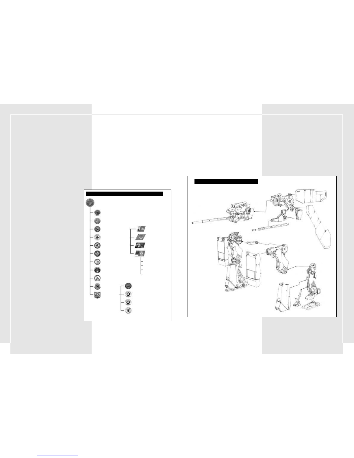
149148
2-1 COMPONENTI DI BASE DI UN VT
I VT sono fondamentalmente costituiti da tre unità:
1. Unità principale
2. Unità di spostamento
3. Unità di armamento
Alcune unità di armamento sono montate direttamente sull'unità
principale, mentre altre operano in modo indipendente.
2-2 SISTEMA OPERATIVO DI UN VT
Il funzionamento di un VT è regolato da un sistema operativo
denominato COOS, che controlla il bilanciere dell'unità di
spostamento, oltre al sistema di puntamento per le varie armi.
Anche con uno stesso tipo di VT, il caricamento di un sistema
operativo differente può ridurre notevolmente le prestazioni in
combattimento. Il sistema COOS, perfezionato attraverso
numerosi esperimenti oltre che sul campo di battaglia, è
completamente sottoposto al segreto militare. È necessario che i
piloti siano consapevoli di questo fatto e, in caso di espulsione
durante il combattimento, provvedano alla distruzione del VT per
garantire la protezione di questa tecnologia.
1-1 IDEAZIONE DEL VT
Il VT (Vertical Tank) ha una storia piuttosto breve, dato che è stato
effettivamente utilizzato come arma solo negli ultimi otto anni.
Tuttavia, il numero estremamente alto di organizzazioni che hanno
iniziato a impiegare il VT ne dimostra il grande potenziale come
arma militare.
Lo sviluppo degli armamenti ha raggiunto un punto di saturazione
e la riduzione delle armi ha portato all'eliminazione di numerosi
progetti militari ed eserciti non più necessari. Con la devastante
potenza di fuoco di cui dispone e la possibilità di essere pilotato
da una sola persona, il VT è destinato a sostituire i carri armati e
diventare l'arma principale per la maggior parte delle
organizzazioni.
1-2 NOZIONI DI BASE SULL UTILIZZO MILITARE
DEL VT
Finora il VT non ha trovato un ampio utilizzo come arma militare,
essendo stato impiegato a livello sperimentale in conflitti locali
solo in due occasioni. Attualmente, la documentazione
relativa all'utilizzo militare del VT è incompleta. Per
conoscerne tutto il potenziale, è necessario attendere il
completamento di ulteriori ricerche. Il potenziale bellico
del VT aumenterà a seconda delle dimensioni e dell'ambito
dei futuri conflitti. I VT sono utilizzati principalmente come
armi a elevata potenza di fuoco, particolarmente efficaci
quando vengono impiegate in gruppo. Un altro importante
aspetto da tenere in considerazione è che il VT è stato
utilizzato per un periodo relativamente breve rispetto alle
armi o ai veicoli precedenti. Per assicurare l'efficienza dei
VT, è pertanto assolutamente fondamentale la copertura
dei rinforzi.
1-3 DOVERI DELLE UNITÀ SPECIALI
CORAZZATE
Le unità panzer che utilizzano il VT come equipaggiamento
militare sono chiamate a ricoprire ruoli di estrema
importanza. In un combattimento con fanteria mobile, le
unità corazzate possono essere utilizzate per la distruzione
o la cattura del nemico, l'assalto di accampamenti avversari
e l'occupazione di aree strategiche. I VT vengono impiegati
principalmente in plotoni come unità mobili d'attacco
o unità difensive di contrattacco. Inoltre, dato che il tempo
e la topografia non rappresentano un problema per i VT,
questi svolgono un ruolo fondamentale per l'attacco di
aree con topografia complessa. Utilizzato in combinazione
con unità mobili (carri armati), il VT consente di aumentare
la potenza di fuoco complessiva. Talvolta può essere
impiegato insieme a forze aeree o navali per la conquista
di posizione chiave o nell'ambito di strategie che
prevedono attacchi dietro le linee nemiche.
1-4 FORMAZIONE DI UNA DIVISIONE
SPECIALE PANZER
Una divisione panzer è formata da un avamposto di
comando, tre battaglioni di VT, un battaglione di carristi, un
battaglione di artiglieria, un battaglione da ricognizione, un
battaglione di genieri, un battaglione addetto alle
comunicazioni, un battaglione antiaereo, un battaglione
aereo e un battaglione rinforzi (diagramma sulla destra). La
divisione rinforzi è composta da un battaglione di
rifornimento, un battaglione addetto alla manutenzione
delle armi, un battaglione trasporti e un battaglione
medico. Un battaglione di VT è composto da quattro
compagnie di VT, ognuna delle quali include tre plotoni di
VT e un plotone di supporto per gli armamenti, con tre VT
in ciascun plotone. Il plotone di supporto svolge
fondamentalmente una funzione di appoggio e non
conduce mai attacchi autonomamente.
1-5 ORGANIZZAZIONE DI UN PLOTONE DI VT
Un plotone di VT comprende tre piloti, ai comandi delle tre classi
di VT disponibili: leggeri, medi e pesanti. La scelta del tipo di VT
dipende dalle caratteristiche della missione assegnata. Prima
dell'avvio di una missione, il pilota richiede il tipo di VT desiderato.
Il trasporto dei VT e le attrezzature per i plotoni di VT sono forniti
dal battaglione di equipaggiamento alle diverse compagnie, che
quindi utilizzano i trasporti per distribuire il materiale ai vari
canali. A ogni VT sono assegnati tre addetti alle riparazioni (uno in
capo e due aiutanti). A seconda del tipo di VT, può inoltre essere
assegnato un ufficiale addetto agli equipaggiamenti, responsabile
del controllo di tutte le attrezzature. Benché in genere ottengano
gli equipaggiamenti dai trasporti della compagnia, nelle situazioni
di emergenza i plotoni di VT ricorrono ai battaglioni rifornimenti
della divisione. Il battaglione addetto alla manutenzione delle armi
è inoltre responsabile di operazioni su larga scala come la
sostituzione di interi gruppi di componenti.
SEZIONE 1. IDEAZIONE DI VT E DIVISIONE SPECIALE PANZER SEZIONE 2. INTRODUZIONE AI VT
7a Divisione Speciale Panzer
32mo Battaglione Speciale Corazzato
33mo Battaglione Speciale Corazzato
34mo Battaglione Speciale Corazzato
3a Compagnia Speciale Corazzata
4a Compagnia Speciale Corazzata
5a Compagnia Speciale Corazzata
6a Compagnia Speciale Corazzata
‡Plotone di VT
‡Plotone di VT
‡Plotone di VT
‡ Plotone di
supporto
Battaglione rifornimenti
Battaglione trasporti
Battaglione medico
Battaglione addetto alla manutenzione delle armi
80mo Battaglione carristi
Battaglione di ricognizione
Battaglione genieri
Battaglione antiaereo
Battaglione comunicazioni
Battaglione aereo
Battaglione di artiglieria
Rinforzi
FORMAZIONE DI UNA DIVISIONE SPECIALE PANZER
DIAGRAMMA DELLA STRUTTURA DI UN VT
Giunto sferico (asse x)
assi x e y
asse z
asse x
asse x
I cambiamenti di direzione sono controllati da questi componenti
Giunto sferico
Giunto sferico
Page 77

151150
2-10 ARMI CARICATE SUI VT
270mm RIFLE (FUCILE da 270 mm)
Quest'arma spara munizioni perforanti a bassa traiettoria.
200mm ASSAULT RIFLE (FUCILE D´ ASSALTO
da 200 mm)
Benché disponga di una gittata ridotta, il sistema di caricamento
automatico assicura la più elevata capacità di tiro rapido.
270mm ASSAULT RIFLE (FUCILE D ´ASSALTO
da 270 mm)
Con un massimo di cinque colpi in tiro rapido, questo fucile
dispone di una notevole potenza distruttiva che lo rende la
principale arma anti-VT. Tuttavia, rispetto ad altri modelli della
stessa generazione, la gittata è relativamente limitata.
315mm TWIN RIFLE (FUCILE A CANNA DOPPIA
da 315 mm)
Quest'arma spara due proiettili perforanti contemporaneamente.
315mm RAPID FIRE RIFLE (FUCILE A TIRO
RAPIDO da 315 mm)
Con la capacità di sparare una raffica di tre colpi, quest'arma
assicura un'efficienza di tiro rapido superiore rispetto a un
normale fucile.
355mm RAPID FIRE RIFLE (FUCILE A TIRO
RAPIDO da 355 mm)
Con la capacità di sparare una raffica di tre colpi, quest'arma
assicura un'efficienza di tiro rapido superiore rispetto a un
normale fucile.
320mm SNIPER RIFLE (FUCILE DI PRECISIONE da
320 mm)
Quest'arma, progettata per colpire i bersagli da grande distanza,
dispone di una portata di tiro superiore rispetto a un normale
fucile.
AK19-4A RECOILESS RIFLE (FUCILE A RAZZI
AK19-4A)
Quest'arma spara munizioni altamente esplosive. Pur essendo
leggera e dotata approssimativamente della stessa potenza di fuoco
di un fucile, le munizioni sono relativamente facili da evitare a
causa della bassa velocità.
AK19-77 RECOILESS RIFLE (FUCILE A RAZZI
AK19-77)
Quest'arma spara munizioni altamente esplosive con spolette
a contatto, che esplodono e danneggiano il nemico anche senza un
colpo diretto.
315mm SMOOTH BORE GUN (CANNONE A CANNA
LISCIA da 315 mm)
Quest'arma spara munizioni APFSDS a bassa traiettoria e dispone di
una portata di tiro superiore rispetto al fucile.
2-3 TIPI DI VT
I VT sono classificati per tipo in base al peso. Esistono VT leggeri,
medi e pesanti.
1. VT leggeri
La caratteristica principale di questo modello è la mobilità.
È stato sviluppato per l'utilizzo in situazioni che richiedono
l'inseguimento di nemici in fuga o per l'attacco a basi
nemiche dopo la distruzione della potenza di fuoco
principale. I VT leggeri possono essere trasportati da
velivoli e sono progettati per essere sganciati su posizioni
chiave. Possono quindi risultare fondamentali per gli
attacchi aerei alle basi nemiche.
2. VT medi
I VT di classe media costituiscono la potenza di fuoco
principale di una divisione speciale panzer. Una delle loro
caratteristiche fondamentali è la capacità di assicurare
potenza di fuoco e una robusta corazza, senza rinunciare ad
agilità e rapidità di movimento. Dei tre tipi di VT, i VT medi
sono i più numerosi e quelli che offrono le maggiori varianti,
grazie alla possibilità di montare corazza e armi aggiuntive.
3. VT pesanti
I VT di questo tipo sono dotati di una corazza molto robusta
e di un'enorme potenza di fuoco, pur essendo meno
maneggevoli dei VT leggeri o medi. Vista la corazza e la
potenza di fuoco di cui sono dotati, i VT pesanti vengono
utilizzati principalmente per la difesa di basi e posizioni
chiave.
2-4 SPOSTAMENTO
Un VT di classe media dispone di una velocità media di
spostamento di 100 km/h e può raggiungere una distanza massima
di 205 km dall'hangar. Questi valori di base possono variare a
seconda della manutenzione dei componenti, della topografia e
delle capacità del pilota.
Il bilanciere, che controlla la stabilità dell'unità di spostamento,
influenza il movimento del VT. La capacità del bilanciere è
indicata in punti: quanti più sono i punti del bilanciere, tanto
maggiore è la stabilità del VT.
2-5 SERBATOIO DI CARBURANTE E SERBATOI
DI RISERVA
Un serbatoio di carburante fisso è montato sull'unità principale
del VT. La capacità del serbatoio dipende dal tipo di serbatoio
utilizzato. Il VT M-7 Decider, l'arma principale per le forze della
Pacific Rim Organization, ha una capacità di circa 22.700 litri e
può operare per circa cinque minuti con ciascun serbatoio.
Alcuni VT dispongono di serbatoi di riserva che possono
aumentarne il tempo operativo. Il numero di serbatoi di riserva
varia a seconda del tipo di VT, ma in genere un VT dispone solo
di uno o due serbatoi di riserva.
Un serbatoio di riserva ha una capacità di 22.700 litri.
Premendo il pulsante Tank Detach (Sgancio serbatoio) sulla
console principale è possibile sganciare i serbatoi supplementari
e alleggerire il VT, aumentandone velocità e maneggevolezza. Una
volta esaurito un serbatoio di carburante, assicurati di sganciarlo
rapidamente.
2-6 CONSUMO DI CARBURANTE E TEMPO DI
SPOSTAMENTO STIMATO
È possibile rifornire il VT e sostituire il carburante consumato in
combattimento inviando una richiesta di rifornimenti. Se si
esaurisce il carburante e non è possibile ricevere rifornimenti,
può essere necessario abbandonare il VT.
Per evitare questa situazione, nelle istruzioni che precedono il
combattimento viene riportata una stima del tempo necessario
per lo spostamento. È necessario valutare il tempo di
spostamento stimato per ciascun combattimento e decidere il
numero di serbatoi di riserva necessari.
La marcia più efficiente in termini di consumo di carburante è la
terza, che offre inoltre la velocità e il movimento ottimali per il
pattugliamento. È possibile aumentare il tempo di spostamento
riducendo al minimo gli spostamenti rapidi e le altre manovre
che comportano un elevato consumo di carburante.
2-7 CORAZZA DIFENSIVA
La potenza difensiva di un VT è denominata "resistenza della
corazza". Un indicatore sul pannello di controllo mostra quattro
differenti livelli di resistenza. Ogni volta che viene colpito, il VT
subisce danni e l'indicatore diminuisce. Quanto più si riduce
l'indicatore, tanto più il pilota è a rischio. Se l'indicatore scende
ai livelli di pericolo viene visualizzato un messaggio. In tal caso,
è necessario ritirarsi dal combattimento o effettuare l'espulsione
appena possibile (per ulteriori informazioni sull'espulsione,
consulta le sezioni da 4-19 a 4-21). Alcuni tipi di VT supportano
una corazza aggiuntiva.
2-8 ARMI PRINCIPALI E ARMI SECONDARIE
Le armi dei VT, suddivise in principali e secondarie, non
corrispondono alle armi tradizionali. Fondamentalmente, le armi
principali sono montate sulle unità di armamento del VT, mentre
quelle secondarie in qualsiasi altro punto. La posizione in cui
è montata un'arma consente di stabilirne il tipo. Le armi non
sono classificate per potenza.
2-9 PESO MASSIMO CONSENTITO PER LE ARMI
Le armi dei VT devono essere considerate opzionali. Alcune armi
possono essere utilizzate per qualsiasi VT, mentre altre variano
a seconda del VT su cui sono montate. È possibile scegliere tre
armi principali e tre secondarie. Il peso delle armi che possono
essere caricate varia a seconda del tipo di VT. Per semplificare la
scelta delle armi, viene visualizzato il peso massimo consentito,
ovvero il peso totale delle armi che il VT è in grado di
trasportare.
FUCILE da 270 mm
Page 78

153152
SQUALL - ANTI-VT GUIDED MORTAR (MORTAIO
GUIDATO ANTI-VT)
Questa è l'unica arma anti-VT con angolo di tiro elevato e dotata
di capacità di ricerca del bersaglio.
RAILGUN A (CANNONE ELETTROMAGNETICO A)
Questa è la più recente arma sviluppata dalle forze della Pacific
Rim Organization. Utilizzando un impulso elettromagnetico,
quest'arma spara munizioni a velocità estremamente elevate, con
una gittata e una potenza di fuoco senza confronti.
RAILGUN B (CANNONE ELETTROMAGNETICO B)
Un cannone sviluppato da Hai Shi Dao. Utilizzando un impulso
elettromagnetico, quest'arma spara munizioni a velocità
estremamente elevate, con una gittata e una potenza di fuoco
senza confronti.
HVM LAUNCHER (LANCIARAZZI HVM)
Quest'arma spara munizioni perforanti con propulsione a
reazione. Benché disponga di una gittata e una potenza di fuoco
tra le più elevate, non è equipaggiata con un sistema di ricerca
del bersaglio.
225mm HOWITZER (OBICE da 225 mm)
Quest'arma spara granate con una traiettoria ad arco. Pur non
essendo particolarmente distruttiva, è in grado di danneggiare la
zona circostante al punto di impatto e risulta molto efficace per
colpire aree in cui sono concentrati numerosi mezzi corazzati.
305mm HOWITZER (OBICE da 305 mm)
Quest'arma spara granate con una traiettoria ad arco. Pur non
essendo particolarmente distruttiva, è in grado di danneggiare la
zona circostante al punto di impatto e risulta molto efficace per
colpire aree in cui sono concentrati numerosi mezzi corazzati.
370mm HOWITZER (OBICE da 370 mm)
Quest'arma spara granate con una traiettoria ad arco ed è in
grado di danneggiare la zona circostante al punto di impatto. A
seconda dell'utilizzo, può risultare molto efficace.
550mm HOWITZER (OBICE da 550 mm)
Quest'arma spara granate con una traiettoria ad arco. Dispone di
una notevole potenza distruttiva ed è in grado di danneggiare
seriamente la zona circostante al punto di impatto.
8 CAPACITY MLRS (LANCIARAZZI MULTIPLO A
8 COLPI)
Questo lanciarazzi a 8 colpi spara razzi di grandi dimensioni con
un angolo di tiro elevato. L'ampio raggio della zona danneggiata
dall'esplosione dei razzi rende l'arma molto efficace per la
neutralizzazione di aree di grandi dimensioni.
355mm SMOOTH BORE GUN (CANNONE A CANNA
LISCIA da 355 mm)
Quest'arma spara munizioni APFSDS a bassa traiettoria e dispone di
una portata di tiro superiore rispetto al fucile.
430mm SMOOTH BORE GUN (CANNONE A CANNA
LISCIA da 430 mm)
L'arma più grande di questo tipo, con una potenza distruttiva e una
portata di tiro più che soddisfacenti.
67mm CHAIN GUN (CANNONE A CATENA da 67 mm)
Quest'arma dispone di una capacità di tiro rapido molto elevata
e spara piccole munizioni perforanti. Benché risulti inefficace
contro i VT per la potenza di fuoco relativamente limitata, è molto
efficiente contro elicotteri d'assalto e mezzi corazzati.
80mm CHAIN GUN (CANNONE A CATENA da 80 mm)
Quest'arma dispone di una capacità di tiro rapido molto elevata
e spara piccole munizioni perforanti. Benché risulti inefficace
contro i VT per la potenza di fuoco relativamente limitata, è molto
efficiente contro elicotteri d'assalto e mezzi corazzati.
100mm CHAIN GUN (CANNONE A CATENA da 100 mm)
Quest'arma dispone di una capacità di tiro rapido molto elevata
e spara piccole munizioni perforanti. Benché risulti inefficace
contro i VT per la potenza di fuoco relativamente limitata, è molto
efficiente contro elicotteri d'assalto e mezzi corazzati.
120mm HEAVY MACHINE GUN (MITRAGLIATRICE
PESANTE da 120 mm)
La potenza distruttiva di quest'arma è superiore rispetto al
cannone a catena. Pur disponendo di un'elevata capacità di tiro
rapido, non è particolarmente efficace come arma anti-VT. Risulta
comunque molto efficiente contro i cannoni mobili di supporto.
140mm HEAVY MACHINE GUN (MITRAGLIATRICE
PESANTE da 140 mm)
La potenza distruttiva di quest'arma è superiore rispetto al
cannone a catena. Pur disponendo di un'elevata capacità di tiro
rapido, non è particolarmente efficace come arma anti-VT. Risulta
comunque molto efficiente contro i cannoni mobili di supporto.
135mm PITO HEAVY MACHINE GUN
(MITRAGLIATRICE PESANTE PITO da 135 mm)
Questa mitragliatrice pesante è alloggiata al di sotto dell'unità
principale del VT. La maggiore potenza rispetto al cannone a catena
e la capacità di tiro rapido la rendono ideale come arma
secondaria.
MK21 ANTI LAND ROCKET CANNON (CANNONE A
RAZZI TERRA-TERRA MK21)
Quest'arma può sparare contemporaneamente sei razzi terra-terra
di medie dimensioni.
MK34 ANTI LAND ROCKET CANNON (CANNONE A
RAZZI TERRA-TERRA MK34)
Quest'arma, che può sparare contemporaneamente quattro razzi
terra-terra di medie dimensioni, può risultare letale per qualsiasi
VT.
CANNONE A CATENA da 67 mm
MITRAGLIATRICE da 120 mm
CANNONE ELETTROMAGNETICO
OBICE da 370 mm
CANNONE A RAZZI TERRA-TERRA MK21
Page 79

155154
FLAME THROWER (LANCIAFIAMME)
Quest'arma per il combattimento ravvicinato, alloggiata al di
sotto dell'unità principale, può provocare l'esplosione di un VT
con un colpo diretto.
STUN ROD (ASTA DA STORDIMENTO)
Un colpo diretto con quest'arma, progettata specificamente per il
combattimento ravvicinato con i VT, provoca una notevole
scarica di elettricità che rende il VT nemico temporaneamente
incapace di reagire.
CUTTER BOOM (LANCIA)
Questa grande lancia è stata perfezionata per il combattimento
corpo a corpo con i VT. È l'arma da combattimento ravvicinato
con la maggiore potenza distruttiva.
AIR TIMED GRENADE (GRANATA A TEMPO)
Questa granata è progettata appositamente per il combattimento
ravvicinato. Grazie alla spoletta a contatto che contiene, la
granata può esplodere e danneggiare il bersaglio anche senza
colpirlo direttamente.
3 ROUND CAPACITY AIR TIMED GRENADE
(GRANATA A TEMPO DA TRE COLPI)
Questa granata è progettata specificamente per il combattimento
ravvicinato. Grazie alla spoletta a contatto che contiene, la
granata può esplodere e danneggiare il bersaglio anche senza
colpirlo direttamente.
SMOKE CHARGER (LANCIAFUMOGENI)
Quest'arma può lanciare quattro granate fumogene. La sua unica
funzione è creare una densa cortina di fumo per ridurre la
visibilità e indebolire le capacità di attacco del nemico.
PROJECTILE ANTI-VT MINE (MINA PROIETTILE
ANTI-VT)
Quest'arma può scaricare contemporaneamente tre mine anti-VT
in grado di proiettarsi in avanti.
PROPELLANT TANK (SERBATOIO DI
CARBURANTE)
Una volta esaurito il carburante, è possibile sganciare il serbatoio
per alleggerire il carico.
ADDITIONAL ARMOR (CORAZZA AGGIUNTIVA)
La corazza aggiuntiva aumenta la resistenza del VT, oltre
a consentire al pilota di utilizzare i missili guidati caricati nei tubi
di lancio della corazza. Premi F1 per sganciare i missili in
combattimento.
REPLACEMENT SUPPLY (RIFORNIMENTI)
I rifornimenti, che includono munizioni e carburante, vengono
forniti su richiesta tramite un elicottero di rifornimento.
BOOM BOX (MANGIANASTRI)
Questo antico mangianastri è stato ritrovato nel magazzino del
campo di addestramento. Puoi appenderlo all'interno
dell'abitacolo per ascoltare musica durante il combattimento.
12 CAPACITY MLRS (LANCIARAZZI MULTIPLO A
12 COLPI)
Questo lanciarazzi a 12 colpi spara razzi di grandi dimensioni con
un angolo di tiro elevato. L'ampio raggio dell'area danneggiata
dall'esplosione dei razzi rende l'arma molto efficace per la
conquista di aree di grandi dimensioni.
DUAL POD COMPACT MISSILE LAUNCHER
(LANCIAMISSILI COMPATTO A DUE TUBI DI
LANCIO)
Questo lanciamissili compatto a due tubi di lancio è alloggiato al
di sotto dell'unità principale del VT.
TRIPLE POD COMPACT MISSILE LAUNCHER
(LANCIAMISSILI COMPATTO A TRE TUBI DI
LANCIO)
Questo lanciamissili compatto a tre tubi di lancio è alloggiato al
di sotto dell'unità principale del VT.
ASLAM ANTI-VT GUIDED MISSILE (MISSILE
GUIDATO ANTI-VT ASLAM)
Il missile ASLAM (Advanced Stand-0ff Land Attack Missile) è
dotato di un sistema di guida ad infrarossi. La programmazione
degli schemi di spostamento del VT migliora la capacità di
acquisizione del bersaglio, producendo un numero estremamente
alto di colpi diretti.
POZIT ANTI-VT GUIDED MISSILE (MISSILE
GUIDATO ANTI-VT POZIT)
Un missile dotato di un sistema di guida ad infrarossi che, per
quanto inferiore rispetto all'ASLAM, risulta comunque un'arma
molto precisa e distruttiva.
DUAL LOAD COMPACT GUIDED MISSILE (DOPPIO
MISSILE GUIDATO COMPATTO)
Questo lanciamissili compatto con due missili guidati è alloggiato
al di sotto dell'unità principale del VT. Sebbene le prestazioni non
siano elevate, è equipaggiato con un sistema di ricerca del
bersaglio.
AVTDV GUIDED MISSILE (MISSILE GUIDATO
AVTDV)
Questo grande missile anti-VT, anche noto come "killer di VT", è
il più letale tra i missili, grazie al sistema di guida avanzato,
all'ampia portata di tiro e alla notevole potenza distruttiva.
ALC205 PLASMA TORCH (TORCIA AL PLASMA
ALC205)
Progettata specificamente per il combattimento ravvicinato con
i VT, quest'arma si rivela estremamente distruttiva ed è in grado
di abbattere un nemico con un solo colpo diretto.
ALC22B PLASMA TORCH (TORCIA AL PLASMA
ALC22B)
Progettata specificamente per il combattimento ravvicinato con
i VT, quest'arma si rivela estremamente distruttiva ed è in grado
di abbattere un nemico con un solo colpo diretto.
NAPALM
Le munizioni al napalm possono essere caricate in uno dei
lanciamissili compatti alloggiati al di sotto dell'unità principale
del VT. Offrendo la possibilità di incendiare un'area predefinita,
il napalm è ideale per la neutralizzazione di bersagli al suolo. Un
VT colpito direttamente da una munizione al napalm ne verrà
incendiato.
TORCIA AL PLASMA ALC205
MISSILE GUIDATO ANTI-VT
GRANATA A TEMPO
Page 80

157156
2-11 PUNTAMENTO DELLE ARMI CON
TRAIETTORIA CURVA SULLA MAPPA DA
COMBATTIMENTO
Per utilizzare un'arma con traiettoria di tiro curva è innanzitutto
necessario agganciare il bersaglio. Quando si sceglie un'arma di
questo tipo, il bersaglio, la direzione di tiro e il punto di impatto
del proiettile vengono visualizzati nella mappa da combattimento
su una linea bianca. È possibile utilizzare queste informazioni per
cercare di colpire il nemico anche senza averlo agganciato.
2-12 SPOLETTA MAGNETICA
A differenza delle spolette a contatto utilizzate per la normale
artiglieria, le munizioni per il fucile a razzi AK19-77 e le granate a
corto raggio dispongono di spolette magnetiche. Queste spolette
utilizzano il magnetismo per l'individuazione del bersaglio ed
esplodono entro una distanza specifica. In tal modo, non è
necessario colpire direttamente il bersaglio per danneggiarlo. In
un combattimento tra VT veloci e leggeri, le spolette magnetiche
possono svolgere un importante ruolo di supporto per l'attacco
al nemico.
2-13 DIFESA ANTIRADAR
Per la difesa dai missili guidati tramite radar, il VT è stato
equipaggiato con un'unità per la dispersione di lamine antiradar.
Quando viene lanciato un missile contro il VT, questa unità
esplode in quattro direzioni, disperdendo in aria lamine di
alluminio che interferiscono con il sistema di puntamento del
missile e gli impediscono di colpire il bersaglio.
Eseguire uno spostamento laterale dopo avere sganciato la difesa
antiradar è il modo più efficiente per schivare un missile.
Traiettoria curva
Traiettoria dritta
TRAIETTORIA CURVA E TRAIETTORIA DRITTA
3-1 ELEMENTI INTRODOTTI NEI SISTEMI COOS
DI SECONDA GENERAZIONE
Attualmente il sistema COOS che controlla tutti i movimenti del
VT è giunto alla seconda generazione, ampliando le funzionalità
disponibili per i VT. Oltre a una superiore potenza di
elaborazione, il COOS dispone di un nuovo sistema di guida per
le armi anti-VT e di un sistema di tiro con valutazione del
bersaglio, denominato FSS. Questi nuovi componenti aumentano
ulteriormente la potenza distruttiva del VT. Di seguito sono
elencate molte delle funzioni offerte dai sistemi COOS di seconda
generazione.
3-2 FUNZIONE FSS
Il sistema di tiro con valutazione del bersaglio, o FSS, analizza lo
schema di spostamento del bersaglio, la distanza percorsa dal
proiettile e il relativo tempo di volo, quindi sposta
automaticamente il mirino sulla successiva posizione più
probabile del nemico. Premendo il pulsante FSS è possibile
passare dal sistema di puntamento FSS al sistema di puntamento
normale e viceversa. Per ulteriori informazioni sulla funzione
FSS, consulta la sezione 5-4.
3-3 FUNZIONE DI OVERDRIVE
Questa funzione consente di aumentare la velocità del VT per un
breve periodo di tempo, disattivando il "limitatore di velocità"
che protegge dal logoramento i vari giunti. Per ulteriori
informazioni sulla funzione di overdrive, consulta la sezione 4-6.
3-4 FUNZIONE STEALTH
La funzione Stealth inclusa nel VT consente di evitare
l'intercettazione da parte dei radar. A tale scopo è stato
necessario utilizzare vernici che assorbono le emissioni radar,
migliorare i condotti di scarico dei gas e rendere più
aerodinamico lo scafo principale.
3-5 ARMI GUIDATE
Una delle principali nuove caratteristiche del sistema COOS di
seconda generazione è il maggiore impiego di armi guidate. Sono
stati aggiunti nuovi missili guidati anti-VT al sistema attivo di
guida laser già in uso. Questo sistema analizza gli schemi di
spostamento del VT e prevede la successiva posizione del nemico
utilizzando in tempo reale la funzione FSS, in modo da aumentare
la precisione di puntamento. Si prevede che il nuovo sistema si
rivelerà estremamente efficace nei combattimenti anti-VT.
SEZIONE 3. FUNZIONI SPECIALI
DEI SISTEMI COOS DI SECONDA
GENERAZIONE
4-1 SEQUENZA DI AVVIO
Quando si prende posto in un VT prima di un combattimento, la
batteria, il serbatoio e le armi del VT sono al livello massimo. La
sequenza di avvio del VT è indicata di seguito.
1. Chiudere il portello dell'abitacolo
Premi il pulsante Cockpit Hatch (Portello abitacolo) sulla
destra. È importante verificare sempre se il portello è aperto
o chiuso.
2. Premere il pulsante di accensione
Premi il pulsante Ignition (Accensione) al di sotto del
pulsante Cockpit Hatch (Portello abitacolo). Il motore
verrà avviato e l'abitacolo sarà alimentato dal generatore.
Dopo il caricamento del sistema operativo del VT, verrà
visualizzato automaticamente un semplice controllo delle
funzioni, prima della schermata delle funzioni di avvio.
3. Attivare le funzioni di avvio
Dopo il controllo delle funzioni, è necessario attivare
ognuna delle seguenti funzioni per verificarne l'operatività.
Azionale una ad una con l'indice per l'accensione.
• OSS (Oxygen Supply System) – Rifornisce in modo
costante l'abitacolo di ossigeno respirabile.
• FCS (Filter Control System) – Interruttore che attiva il
sistema di eliminazione dei gas di scarico, rimuovendoli
e stabilizzando il motore.
• VT-LM (VT-Location Measurement) – Sistema di
valutazione e localizzazione. Una funzione utilizzata per
visualizzare automaticamente il proprio VT sulla mappa da
combattimento.
•BM (Buffer Material) – Un sistema che emana un
materiale protettivo che avvolge l'abitacolo per
proteggerlo dagli attacchi. L'abitacolo e il torso del VT
vengono ricoperti da un gel molto resistente per
assicurarne la protezione.
• FFR (Fuel Flow Rate) – Un sistema che regola il flusso di
carburante, inviando la quantità appropriata di carburante
in base alle condizioni del motore.
4. Premere il pulsante Start
Dopo avere completato la sequenza di avvio iniziale, verrà
visualizzata un'immagine dell'ambiente circostante.
L'energia viene fornita ai vari giunti del VT tramite un
attuatore. Una volta che tutti i sistemi hanno raggiunto il
livello di stabilità, premi il pulsante Start. Al completamento
delle varie funzioni, il VT entrerà in modalità di avvio e sarà
possibile iniziare a controllarlo.
4-2 BLOCCO DEL VT DURANTE L AVVIO
Se si preme il pulsante Start PRIMA che tutti i sistemi abbiano
raggiunto il livello di stabilità, i giunti non saranno attivati, la
sequenza di avvio verrà annullata e il VT entrerà in blocco.
Questa funzionalità evita il danneggiamento del VT dovuto al
superamento delle limitazioni strutturali. In caso di blocco
durante l'avvio, attendi la riaccensione dei vari sistemi e ripeti
l'avvio del VT premendo nuovamente il pulsante Start.
SEZIONE 4. CONTROLLI DEI VT
Livello di stabilità
CONTROLLO DELLO STATO DEI SISTEMI PRIMARI
SCHERMATA DI AVVIO
Page 81

159158
CONTROLLI DI BASE
4-3 SPOSTAMENTO E ARRESTO
Lo spostamento e l'arresto sono i due movimenti fondamentali
del VT. La leva del cambio consente di controllare cinque marce.
Premendo l'acceleratore, i giri del motore aumentano e il VT si
sposta in avanti. Per muoverlo all'indietro, posiziona la leva del
cambio sulla retromarcia. Per arrestare il VT, solleva il piede
dall'acceleratore e premi il pedale del freno. Evita di curvare
bruscamente durante gli spostamenti ad alta velocità: il VT
potrebbe rovesciarsi.
4-4 ACCELERAZIONE E DECELERAZIONE
La quantità di accelerazione e decelerazione dipende dalla
pressione esercitata sull'acceleratore. Per frenare è possibile
azionare il pedale del freno o scalare le marce. Lasciando il
cambio in folle, la velocità del VT è di 0 km/h. A ogni aumento di
marcia si acquista velocità, con una riduzione dell'effetto di
coppia. Nelle aree in cui non è possibile aumentare la velocità in
modo regolare, le marce più basse ottimizzano il consumo di
carburante. Ingranando la retromarcia, il VT invertirà direzione.
4-5 ROTAZIONE
Per ruotare il VT, premi o sulla leva di rotazione sinistra.
La velocità di rotazione aumenta in proporzione alla pressione
esercitata sulla leva nella direzione corrispondente. Fai
attenzione: se il bilanciere non riesce a mantenere l'equilibrio, il
VT può rovesciarsi.
4-6 OVERDRIVE
Questa funzione, sviluppata su richiesta di numerosi piloti
esperti, disattiva il limitatore di velocità che protegge i vari giunti
dal logoramento, con un conseguente aumento della velocità. Per
disattivare il blocco del limitatore, premi il pulsante Overdrive.
Premendo nuovamente il pulsante, il blocco verrà riattivato.
Poiché l'overdrive comporta un consumo di carburante triplicato
rispetto alle normali condizioni, è necessario utilizzare questa
funzione con cautela.
4-7 FUNZIONE DI SPOSTAMENTO RAPIDO
Questa funzione è uno dei mezzi speciali a disposizione del VT per
evitare i colpi del nemico e rappresenta una delle principali
differenze tra il VT e un comune carro armato. Grazie alle
funzionalità di programmazione del sistema operativo, la
funzione di spostamento rapido consente di muoversi
velocemente verso destra o sinistra, oltre che di ristabilire
l'equilibrio quando il VT sta per rovesciarsi. Lo spostamento
rapido consiste in un movimento veloce in una delle quattro
direzioni seguendo percorsi pre-programmati e viene eseguito
combinando l'utilizzo dell'acceleratore e del bilanciere. Il
bilanciere rinforza automaticamente le aree e i giunti più soggetti
al logoramento. Per eseguire uno spostamento rapido, premi
o ^ sulla leva di rotazione e aziona contemporaneamente il
pedale dello spostamento rapido. Questa funzione è
estremamente utile per evitare gli attacchi del nemico. È possibile
eseguire un diverso movimento premendo il pedale dello
spostamento rapido senza usare la leva di rotazione. In questo
caso, il VT compie un balzo in avanti. Eseguendo la stessa
operazione mentre è innestata la retromarcia, il VT compie un
balzo indietro.
4-8 LIMITI FUNZIONALI DELLO SPOSTAMENTO
RAPIDO
Lo spostamento rapido sottopone a una notevole sollecitazione le
sezioni dei giunti del VT. Per ridurre il logoramento, viene
utilizzata una grande quantità di energia tramite l'attuatore.
L'energia creata dal generatore viene trasmessa alla batteria
principale, la cui potenza tuttavia si riduce notevolmente a ogni
esecuzione di uno spostamento rapido. Se la potenza disponibile
non è sufficiente, lo spostamento rapido viene automaticamente
annullato. Quando la batteria sta per esaurirsi, ne viene
segnalato il surriscaldamento. In tal caso, non utilizzare la
funzione di spostamento rapido.
4-9 REGOLATORE DELLO SPOSTAMENTO
RAPIDO
Ogni volta che il movimento del VT supera la capacità del
bilanciere, esiste la possibilità che il VT si rovesci. Un
rovesciamento può verificarsi effettuando manovre imprudenti,
svoltando ad alta velocità o quando si viene colpiti dal nemico.
Quando il VT sta per rovesciarsi, è possibile ristabilirne
l'equilibrio premendo il pedale dello spostamento rapido. Se
tuttavia il livello della batteria è basso, non sarà possibile
eseguire questa manovra. In caso di rovesciamento, rilascia
l'acceleratore e quindi premilo nuovamente per risollevare il VT.
4-10 FUNZIONE DI SPEGNIMENTO
In caso di danni superiori alla capacità massima di
danneggiamento, il VT si spegne automaticamente per proteggere
le varie sezioni dei giunti. Quando si verifica uno spegnimento,
tutti i blocchi vengono disattivati e il VT si arresta. Per riattivare
il VT, ripeti rapidamente la sequenza di avvio.
FUNZIONE DI SPOSTAMENTO RAPIDO
4-11 CONTROLLI DEL MANIPOLATORE
In un VT il manipolatore controlla un braccio meccanico, in grado
di aprire e chiudere porte e di spostare carichi, montato sulla
sinistra dello scafo principale. Per attivarlo, è sufficiente
premere il pulsante del manipolatore. Centrando il
manipolatore su un determinato punto e premendo il pulsante
dell'arma secondaria è possibile afferrare l'oggetto desiderato.
Poiché per usare il manipolatore è necessario premere il
pulsante dell'arma secondaria, quest'ultima non può essere
utilizzata mentre è attivato il manipolatore.
USO DEL MANIPOLATORE PER IL
CONTROLLO DI UN MONTACARICHI
USO DEL MANIPOLATORE PER
L APERTURA E LA CHIUSURA DI PORTE
MANIPOLATORE
RECUPERO DI OGGETTI CON IL MANIPOLATORE
Puntamento normale dell'arma secondaria
Puntamento in modalità
manipolatore
Page 82

161160
MONITOR DEL VT
4-12 MODIFICA DELLA TELECAMERA
PRINCIPALE
Il campo visivo del VT è determinato dalla telecamera principale,
le cui immagini vengono visualizzate all'interno dell'abitacolo. In
genere, la telecamera è posizionata al centro e inquadra l'area di
fronte al VT. Premendo
,
, o sulla manopola della leva
sinistra, è possibile aumentare l'area visualizzata. Premendo la
manopola della leva di controllo, è possibile riportare al centro
la visuale. Questa funzione e il monitor secondario del VT
(descritto più avanti) consentono di spostare il VT e aumentarne
l'efficacia in combattimento.
4-13 PULIZIA DELLA TELECAMERA
PRINCIPALE
Durante un combattimento è necessaria una perfetta visibilità
tramite lo schermo principale. Se lo schermo viene oscurato da
sporcizia o polvere, premi il pulsante di lavaggio per ripulirlo.
PROSPETTIVE DELLA TELECAMERA
4-14 FUNZIONI DEL MONITOR SECONDARIO
Il pulsante di selezione della modalità per il monitor secondario,
al di sotto del monitor principale, offre quattro opzioni.
• Modalità Front View (Vista frontale)
Visualizza ciò che si trova direttamente di fronte al VT e può
essere utilizzata insieme alla funzione di modifica della vista
per osservare gli oggetti con maggiore chiarezza.
• Modalità Back View (Vista posteriore)
Visualizza ciò che si trova dietro al VT e, come nel caso della
vista frontale, può essere utilizzata insieme alla funzione di
modifica della vista per osservare gli oggetti con maggiore
chiarezza.
• Modalità Lock-On View (Vista agganciamento)
Consente di ingrandire la visuale sul bersaglio agganciato. I
bersagli a grande distanza vengono visualizzati sul monitor
secondario anche senza eseguire ingrandimenti.
• Modalità Sky View (Vista dall'alto)
Visualizza il VT inquadrandolo da un'altezza di 50 metri.
Questa modalità è particolarmente utile per controllare
punti ciechi e osservare il territorio circostante agli oggetti.
4-15 EQUIPAGGIAMENTO PER LA VISIONE
NOTTURNA
Il VT è equipaggiato con un telescopio per la visione notturna,
utile in condizioni di scarsa luminosità, ad esempio di notte o in
ambienti fumosi. Per attivarlo è sufficiente premere il pulsante
del telescopio sul pannello di controllo. Il VT utilizza il sistema
JGVS-V442 di tipo passivo, che proietta una luce a infrarossi
sull'obiettivo e quindi lo visualizza come immagine sullo schermo.
Oltre a essere utile in mancanza di luce o presenza di fumo, il
telescopio per la visione notturna semplifica l'individuazione di
bersagli mimetizzati. Il telescopio ha una portata massima di circa
2,5 km e visualizza l'immagine sul monitor. Se viene utilizzato
nell'oscurità, il telescopio può essere temporaneamente oscurato
dai bagliori dovuti al combattimento o provocati dallo scoppio
delle granate, rendendo impossibile la visione all'esterno del VT.
Sistema completo di comando JCS
4-16 INTRODUZIONE AL JCS
Il sistema JCS utilizza dati strategici e informazioni aggiornate per
aumentare al massimo l'efficacia dei VT. Lo scopo principale del
sistema consiste nel fornire un costante aggiornamento
relativamente a campo di battaglia, forze alleate, nemici e
ulteriori compagnie o battaglioni. Il sistema JCS è progettato per
aumentare l'efficacia complessiva dei VT in combattimento e i
piloti di VT, come i comandanti di plotone, devono essere in
grado di utilizzarlo al meglio.
JCS si basa su una rete che collega il centro di comando dei
trasporti VT con i centri di comando delle compagnie e dei
battaglioni, per facilitare lo scambio di comunicazioni. Il sistema
invia messaggi provenienti dai monitor video del VT, dai satelliti
di ricognizione e da altre divisioni di comando, modifica i dati in
tempo reale all'interno dei centri di comando dei battaglioni,
quindi analizza i dati e li invia ai vari plotoni. I dati vengono
trasmessi ai VT tramite una rete di comunicazione e sono
visualizzati sui vari monitor presenti nell'abitacolo. Grazie a
questo sistema, i piloti possono controllare mappe, individuare
postazioni nemiche e gestire i rinforzi per le forze in campo.
DIAGRAMMA DELLA RETE PER IL
SISTEMA COMPLETO DI COMANDO JCS
Centro di comando dei trasporti VT
VT
Jet da ricognizione
Satellite da ricognizione
Page 83
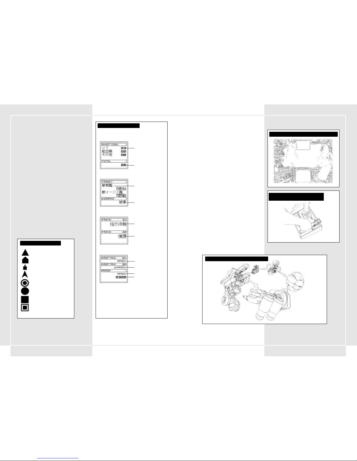
163162
4-17 DISPLAY MULTI-MONITOR
Il display multi-monitor nell'area superiore del monitor
principale è utilizzato per visualizzare le informazioni inviate dal
centro di comando principale. Il multi-monitor non è sempre
visualizzato. Per attivarlo e disattivarlo, premi il pulsante di
apertura/chiusura del multi-monitor.
4-18 INFORMAZIONI VISUALIZZATE NEL
MULTI-MONITOR
Nel multi-monitor sono visualizzate le seguenti informazioni.
1. Mappa da combattimento
Mostra l'area circostante con un raggio di 25 km. Puoi
utilizzare il pulsante di zoom per ingrandire la mappa fino a
un'area con un raggio di 5 km.
2. Informazioni sul VT in uso
Mostra le condizioni e le statistiche attuali relative al VT,
consentendo di controllare la corazza o il carburante
rimanenti.
3. Obiettivo della missione
Mostra le informazioni relative all'obiettivo principale della
missione corrente, segnalando eventuali cambiamenti
improvvisi nella missione. Per i piloti e soprattutto per
i comandanti di plotone è estremamente importante
controllare queste informazioni.
4. Plotone
Mostra esclusivamente dati relativi al comandante di
plotone, consentendo di controllare gli ordini attualmente
impartiti agli altri membri del plotone.
5. Informazioni sul nemico
Mostra dati relativi ai VT nemici, quali portata di tiro delle
armi e potenza d'attacco, oltre a informazioni su varie unità
di supporto.
DISPLAY MONITOR MAPPA
DISPLAY MULTI-MONITOR
CONTROLLO DEL NUMERO DI NEMICI DISTRUTTI
Numero e tipo di nemici distrutti
Numero totale di nemici distrutti
Obiettivo principale
Ordini relativi all'obiettivo principale
SCHERMATA DELL'OBIETTIVO PRINCIPALE
Ordine eseguito dal primo compagno
di squadriglia
Ordine eseguito dal secondo compagno
di squadriglia
STATO DELLA SQUADRIGLIA
Serbatoio di carburante 1
Serbatoio di carburante 2
Corazza aggiuntiva
Numero di punti rimanenti per la
corazza aggiuntiva
STATO DEL VT IN USO
VT alleati
VT
Altre unità di terra (carri armati, cannoni)
Forze aeree (elicotteri, bombardieri)
Punto di impatto stimato per un'arma con traiettoria curva
Proiettili
Punto di impatto stimato per l'arma principale
Punto di impatto stimato per l'arma secondaria
PROCEDURE DI EMERGENZA
4-19 DISPOSITIVO DI ESPULSIONE
Per garantire la protezione del pilota, nei VT è stata introdotta una
funzione di espulsione. Se i danni subiti sono eccessivi, se la
resistenza della corazza si esaurisce (sezione 2-5) o se il VT
raggiunge livelli critici, il pilota deve eseguire l'espulsione il più
rapidamente possibile. Lo strato di gel protettivo che riveste
l'abitacolo si trasforma in una capsula di salvataggio, espulsa
tramite un piccolo razzo posizionato nella parte inferiore.
4-20 INTERRUTTORE PER L´ ESPULSIONE DI
EMERGENZA
L'interruttore per l'espulsione di emergenza è situato sulla destra
della console ed è coperto da un vetro protettivo di colore nero
e giallo.
Dato che l'interruttore è posizionato accanto al pulsante Start, fai
attenzione a non premere quest'ultimo accidentalmente. Quando si
preme l'interruttore, l'abitacolo viene espulso dalla parte
posteriore del VT. Dopo l'espulsione, il rivestimento di gel forma un
involucro che circonda completamente l'abitacolo e lo protegge
dagli urti in fase di atterraggio.
4-21 PROCEDURE PER L ´ESPULSIONE DI
EMERGENZA IN ACQUA
Non essendo resistente all'acqua e impermeabile al 100%, il VT non
può spostarsi in acque con profondità superiori ai 20 metri, poiché
perderebbe la capacità di movimento. In caso di caduta in acque
con profondità superiori, l'acqua inizia a penetrare nel gel di
rivestimento che circonda l'abitacolo, rendendo necessaria
l'espulsione. L'espulsione in acqua avviene in modo analogo a
quella a terra. Il gel di rivestimento forma un involucro che
consente di raggiungere la superficie.
4-22 INCENDIO NELLO SCAFO
In caso di incendio all'interno dello scafo è necessario agire con la
massima rapidità. I danni provocati da un lanciafiamme o da un
eccessivo numero di colpi subiti possono causare un incendio in
grado di danneggiare la corazza del VT e ridurne la resistenza. Se
viene rilevato un incendio e le spie di segnalazione nell'abitacolo
lampeggiano, controlla in quale area si è sviluppato l'incendio
e premi il pulsante dell'estintore sul pannello di controllo.
PROCEDURA DI ESPULSIONE DEL PILOTA
INTERRUTTORE PER L ´ESPULSIONE
DI EMERGENZA
RESISTENZA DELLA CORAZZA AL PUNTO CRITICO
Page 84

165164
5-1 PUNTAMENTO E AZIONAMENTO DELLE ARMI
Il puntamento delle armi viene eseguito utilizzando la leva di
puntamento destra per posizionare il mirino sul nemico. Le armi
montate sull'unità principale sono in grado di muoversi in modo
indipendente, offrendo al VT un raggio di puntamento massimo
di 180ºº. Una volta posizionato il mirino sul nemico, è possibile
azionare l'arma principale o l'arma secondaria premendo
i rispettivi grilletti.
5-2 FUNZIONE DI AGGANCIAMENTO
I VT offrono una speciale funzionalità di agganciamento che
consente di mirare automaticamente su determinati bersagli.
Quando il mirino visualizzato inizia a lampeggiare, è possibile
agganciare il bersaglio premendo il pulsante di agganciamento
sulla leva di puntamento destra. A questo punto, è sufficiente
premere il grilletto dell'arma principale o di quella
secondaria per puntare automaticamente sul nemico. Premi
nuovamente il pulsante di agganciamento per sganciare il
bersaglio, una volta distrutto il nemico o se questo esce dalla
visuale.
Nota: essendo stata appositamente progettata per un utilizzo
anti-VT, la funzione di agganciamento può essere utilizzata
esclusivamente per VT o cannoni nemici.
5-3 PUNTAMENTO IN COMBATTIMENTO
RAVVICINATO
Le armi secondarie del VT offrono diverse opzioni per il
combattimento ravvicinato. Un buon esempio è la torcia al
plasma ALC205, che può essere utilizzata solo su un VT ed è
un'arma piuttosto particolare. È tuttavia necessario fare
attenzione. Quando si utilizza una di queste armi, viene attivata
la modalità di combattimento ravvicinato e il bersaglio è
visualizzato in modo leggermente diverso. Questa modalità di
puntamento è utile per il combattimento ravvicinato contro un
nemico veloce immediatamente di fronte al VT. Il mirino
funzionerà soltanto per i bersagli direttamente davanti al VT.
Premendo il pulsante dell'arma secondaria con l'avversario di
fronte, il VT caricherà il nemico, colpendolo con la torcia al
plasma.
SEZIONE 5. ATTACCO A VT
AGGANCIAMENTO
RAGGIO DI PUNTAMENTO
PORTATA DI TIRO
180
°
PUNTAMENTO ARMA SECONDARIA
Oltre la portata di tiro Entro la portata di tiro
PUNTAMENTO ARMA PRINCIPALE
Oltre la portata di tiro Entro la portata di tiro
Possibile agganciamento Agganciamento eseguito
MIRINI IN MODALITÀ NORMALE E DI
COMBATTIMENTO RAVVICINATO
Modalità normale
Modalità di combattimento
ravvicinato
5-4 FUNZIONE FSS
Il sistema di tiro con valutazione del bersaglio, denominato FSS,
è stato sviluppato per analizzare i dati di combattimento e gli
schemi di spostamento dei VT nemici.
Premendo il pulsante FSS sulla leva di puntamento, è possibile
passare dal sistema di tiro normale a quello con valutazione del
bersaglio, in modo da puntare automaticamente sulla più
probabile posizione successiva del nemico. Premendo
nuovamente il pulsante FSS, verrà ripristinato il sistema di tiro
normale.
Nota: la funzione FSS è stata introdotta nei sistemi operativi COOS
di seconda generazione, pertanto non è disponibile nei VT dotati
di un sistema operativo di prima generazione. La stima dei dati
sugli schemi di spostamento del nemico non è completamente
accurata: un avversario ben addestrato può eseguire movimenti
che il sistema FSS non è in grado di stimare. È pertanto possibile
che per alcuni nemici la funzione FSS risulti inefficace.
5-5 PORTATA DI TIRO DELLE DIVERSE ARMI
Ogni arma dispone di una specifica portata di tiro. Per un pilota
è importante conoscere con precisione la portata massima e la
portata effettiva di ciascuna arma. La portata di tiro effettiva di
ogni arma è riportata sulla sinistra o sulla destra del monitor
principale ed è impostata dal sistema di controllo dell'artiglieria.
La portata ottimale dell'arma principale è riportata sulla destra
del mirino, quella dell'arma secondaria sulla sinistra. La portata
ottimale di entrambe le armi è sovrapposta al mirino. Se
l'avversario esce dalla portata di tiro, viene visualizzato un
messaggio che segnala che il nemico è fuori portata.
5-6 NOTE SULLA PORTATA DI TIRO EFFETTIVA
La portata di tiro effettiva, visualizzata sul monitor principale,
è stata progettata appositamente per il combattimento anti-VT. In
caso di combattimento contro avversari dotati di una corazza più
leggera, ad esempio un carro armato, è possibile che i colpi
abbiano una potenza sufficiente per distruggere anche nemici
fuori portata. Inoltre, la portata di tiro effettiva è programmata
in base allo spessore della corazza dei VT, come definito dagli
standard della Pacific Rim Organization. Pertanto, se un bersaglio
è dotato di una corazza più pesante, esiste la possibilità che non
venga danneggiato, anche se si trova all'interno della portata di
tiro effettiva. Fai attenzione.
UTILIZZO DELLA TORCIA AL PLASMA
Movimento ad alta velocità
LINEE DI TIRO FSS
Posizione del bersaglio agganciato al momento in cui si apre il fuoco
Posizione del bersaglio agganciato all'impatto dei proiettili
Page 85

167166
5-7 UTILIZZO DELLA PORTATA DI TIRO
EFFETTIVA
Un aspetto molto importante per un combattimento anti-VT
è disporre di un equipaggiamento più potente rispetto al nemico,
per poterlo affrontare da una posizione di superiorità. Se la
portata di tiro effettiva delle proprie armi è superiore a quella
dell'avversario, è possibile attaccare il nemico a distanza. Una
portata superiore offre infatti la possibilità di avvicinarsi al
nemico quanto basta per colpirlo, in modo da avere l'opportunità
di distruggerlo senza venirne danneggiati. Non mettere a rischio
il VT e la tua vita se non è necessario.
5-8 ATTACCO DI NEUTRALIZZAZIONE
Le armi come i cannoni a granate, i lanciarazzi e il napalm
esplodono vicino alla superficie del suolo, danneggiando i nemici
entro un determinato raggio. Questo "attacco di
neutralizzazione" può rivelarsi molto efficace contro nemici
raggruppati.
5-9 MODIFICA DELLE ARMI
Uno dei vantaggi principali offerti dai VT rispetto alle altre unità
è la possibilità di essere equipaggiati con un'ampia varietà di
armi. Un VT può essere dotato di tre armi principali e tre
secondarie, ma è possibile azionare solo un'arma di ciascun tipo
per volta. Per scegliere le armi principali e secondarie, premi il
pulsante di controllo delle armi.
5-10 RICARICA DELLE ARMI CON CARICATORE
Alcune armi dell'arsenale utilizzano caricatori. Ogni volta che
è necessario ricaricare un'arma di questo tipo, premi il pulsante
di sostituzione del caricatore. I proiettili rimanenti e il numero
di caricatori supplementari sono indicati nel pannello di
controllo.
SISTEMA DI MODIFICA DELLE ARMI
TIRO DI NEUTRALIZZAZIONE
Portata effettiva = 400 mm
Portata effettiva = 1000 mm
Fuori portata = 1600 mm
PORTATA DI TIRO EFFETTIVA
(Fucile da 270 mm) (0-1500 mm)
PORTATA DI TIRO EFFETTIVA
(Cannone a razzi MK34) (500-1000 mm)
Portata effettiva = 600 mm
Fuori portata = 1600 mm
Fuori portata = 300 mm
6-1 INFORMAZIONI GENERALI
In questa sezione sono illustrate le regole di base per lo
spostamento del VT sul campo di battaglia.
Lo spostamento è utile per uscire dal campo visivo
dell'avversario, evitare aree che possono contenere postazioni
nemiche o allontanarsi dalle zone in cui la potenza di fuoco del
nemico è più concentrata. Si può presupporre che il nemico
concentri i propri VT sui terreni che assicurano la massima
facilità di manovra, pertanto combattere in un'area
particolarmente difficoltosa per i VT può rivelarsi un vantaggio.
Se ci si sposta all'interno di aree in cui il VT ha notevoli
probabilità di essere colpito, può essere necessario richiedere
rinforzi alla sezione genieri.
6-2 CONDIZIONI ATMOSFERICHE E
TOPOGRAFIA
Sul campo di battaglia è indispensabile potersi spostare
indipendentemente dalle condizioni atmosferiche e topografiche.
Questo aspetto è ancora più importante del contatto con il
nemico.
Rispetto a un veicolo su zampe o un carro armato, un VT risente
in misura minore della topografia, sebbene sia facilmente
individuabile dal nemico a causa delle considerevoli dimensioni.
Nelle situazioni in cui è probabile entrare in contatto con il
nemico, occorre tentare di sfruttare al meglio la topografia del
territorio circostante. In particolare con lo sviluppo dei campi di
energia (ECM), diventa fondamentale sfruttare la topografia e
disporre di una buona visuale. In questi casi è essenziale valutare
attentamente i movimenti del nemico ed evitarne l'artiglieria.
•Foresta
Gli alberi offrono il mezzo migliore per nascondere il VT
e proteggerlo dal fuoco nemico.
•Terreno aperto
Non offre alcuna copertura, quindi obbliga il VT a spostarsi
normalmente.
• Strade/valli chiuse
I percorsi su cui il VT si può spostare sono limitati da valli
che possono nascondere imboscate nemiche e in cui è
necessario muoversi con cautela.
Prima di addentrarti in una di queste aree, controlla
attentamente le zone circostanti e verifica l'eventuale
presenza di campi minati sul percorso del VT. Infine, presta
particolare attenzione alle svolte della strada o alle aree che
non possono essere evitate con itinerari alternativi. I ponti
possono rivelarsi estremamente pericolosi.
• Fiumi
Attualmente, l'impermeabilità e la resistenza all'acqua del VT
sono decisamente insufficienti. Sebbene in base ai test
condotti risulti possibile gestire il movimento del VT in
acque con profondità fino a 10 metri, a profondità superiori
l'acqua penetra nelle varie sezioni dei giunti e danneggia il
VT. A 20 metri il VT non risponde ai comandi e si arresta
completamente. Prima di entrare in acqua, è quindi
fondamentale controllarne la profondità.
SEZIONE 6. SPOSTAMENTO DEL VT
Page 86

169168
CONFIGURAZIONE DEL CONTROLLER STEEL BATTALION
Page 87

171170
8-1 INTRODUZIONE
Le comunicazioni sono fondamentali per correlare informazioni
chiave, modificare i piani tra i vari gruppi, semplificare
l'esecuzione degli ordini e velocizzare il trasferimento di nuovi
ordini e informazioni.
Ogni VT è equipaggiato con una radio JARC-F522 per le
comunicazioni.
Il VT del comandante di plotone dispone di due radio JARC-F522
o di una radio JARC-F522 e una JARC-A232. Durante le
comunicazioni radio, è importante pronunciare chiaramente le
parole e fornire rapidamente solo le informazioni essenziali.
Inoltre, per la possibile presenza di dispositivi di intercettazione
del nemico, è fondamentale mantenere segreta la propria
identità utilizzando nomi in codice.
8-2 CANALI PREIMPOSTATI
Nella radio standard dei VT alcuni canali sono preimpostati, in
modo da evitare di perdere tempo per la sintonizzazione durante
il combattimento. La radio dei VT può avere fino a cinque canali
preimpostati.
8-3 PROCEDURE DI COMUNICAZIONE VIA RADIO
Per comunicare via radio, seleziona i canali tramite un'antenna
e premi il pulsante delle comunicazioni per iniziare la
trasmissione. Sono disponibili tre opzioni di comunicazione e
non è possibile modificare la funzione associata a questi pulsanti.
Le opzioni disponibili sono:
• Pulsante di comunicazione 1 – Chiamata/Risposta
• Pulsante di comunicazione 2 – Ripetizione
• Pulsante di comunicazione 3 – Richiesta di rifornimenti
SEZIONE 8. TRASMISSIONI RADIO
1. Communication panel 1 (from the main battalion Argus) begins to flash. This signals
that a message from the main battalion is coming in.
2. Set the tuner on Communications Panel 1.
3. Press Communication Button 1 (respond/call) and open a connection.
"This is Oscar 3. Argus, go ahead."
Il comandante del battaglione invia il messaggio.
"This is Argus. Your division is in a bad spot! Disengage immediately!"
("Qui Argus. La vostra divisione è in pericolo! Disimpegno immediato!")
5. After you hear what was said, press Communication Button 1 (respond/call).
"Oscar 3. I copy that."
6. Finish the communication.
7. If you didn’t hear the message, press Communication Button 2 (repeat).
PROCEDURE DI COMUNICAZIONE
(esempio: ordine di ritirata)
ABITACOLO:
CENTRO DI COMANDO DEL BATTAGLIONE PRINCIPALE:
1. Communication panel 1 (from the main battalion Argus) begins to flash.
This signals that a message from the main battalion is coming in.
2. Set the tuner on Communications Panel 1.
3. Press Communication Button 1 (respond/call) and open a connection.
"This is Oscar 3. Argus, go ahead."
4. The battalion head gives his message.
"This is Argus. Your division is in a bad spot! Retreat immediately!"
5. After you hear what was said, press Communication Button 1 "
6. If you didn’t hear the message, press Communication Button 2 (repeat).
7. Finish the communication.
Il pannello comunicazioni 1 (relativo al battaglione principale Argus) inizia a lampeggiare,
segnalando un messaggio in arrivo dal battaglione principale.
Imposta il sintonizzatore sul pannello comunicazioni 1.
Premi il pulsante di comunicazione 1 (Chiamata/Risposta) e apri un collegamento.
"This is Oscar 3. Argus, go ahead" ("Qui Oscar 3. Argus, proseguite").
4. The battalion head gives his message.
"This is Argus. Your division is in a bad spot! Retreat immediately!"
Al termine del messaggio, premi il pulsante di comunicazione 1 (Chiamata/Risposta).
"Oscar 3. I copy that" ("Oscar 3. Ricevuto").
Se non sei riuscito ad ascoltare il messaggio, premi il pulsante di comunicazione 2 (Ripetizione).
7. Chiudi la comunicazione.
7-1 ORDINI
Fondamentalmente, i battaglioni e le compagnie impartiscono
ordini ai plotoni. Gli ordini vengono comunicati tramite messaggi
di testo, oltre che verbalmente. In genere, prima di ogni missione
vengono fornite le relative istruzioni, in cui sono visualizzate
alcune delle seguenti informazioni:
• Obiettivo della missione
• Informazioni sul nemico
• Situazione delle unità alleate
• Topografia
• Stato del campo di battaglia
• Tempo previsto per il completamento della missione
Dopo le istruzioni, gli ordini sono analizzati da ufficiali di vario
grado per l'elaborazione di un piano di attacco per il plotone.
7-2 ANALISI DELLA MISSIONE
Una volta ricevuto un ordine da uno dei comandanti più alti in
grado (battaglione/compagnia), il comandante del plotone
analizza la missione in base alle principali informazioni
disponibili. L'analisi della missione include:
• Presentazione della missione
• Informazioni sul nemico
• Topografia
• Armi utilizzabili nella missione corrente
• Equipaggiamento e rifornimenti necessari
Prima di completare la preparazione strategica, è necessario
richiedere il tipo di VT desiderato, il relativo armamento
e l'equipaggiamento da utilizzare. È inoltre opportuno controllare
nuovamente gli obiettivi della missione.
Assicurati che tutti i membri del plotone conoscano chiaramente
gli obiettivi della missione, per evitare che commettano errori
durante il combattimento.
7-3 SCELTA DELLE ARMI
I piloti dei VT sono responsabili della scelta delle armi da portare
in combattimento, che devono essere adeguate agli obiettivi della
missione. È possibile scegliere tre armi principali e tre
secondarie, ma non è possibile superare il limite massimo di peso
previsto per il tipo di VT selezionato. È importante tenere
presente che, anche senza superare il limite massimo per il VT, il
trasporto di un peso di poco inferiore a questo limite influisce
negativamente sul bilanciere e può ridurre considerevolmente le
prestazioni del VT.
7-4 SELEZIONE DI CORAZZA AGGIUNTIVA E
ARMI SECONDARIE
Se scegli di equipaggiare il VT con una corazza aggiuntiva,
vengono automaticamente impostati missili corazzati come armi
secondarie, riducendo di uno il numero di armi secondarie
selezionabili. Assicurati che l'aggiunta della corazza non comporti
il superamento del limite massimo di peso.
7-5 SCELTA DEL VT
I plotoni hanno a disposizione tre tipi di VT: leggeri, medi e
pesanti. La scelta del VT dipende dal tipo di missione, ma la
decisione definitiva spetta al pilota. Inoltre, per le missioni che
prevedono un lancio sull'obiettivo è possibile scegliere solo VT
leggeri.
7-6 AGGIUNTA DI CORAZZA E SERBATOI DI
CARBURANTE
In base alla missione da eseguire, puoi scegliere di equipaggiare
il VT con serbatoi di riserva o una corazza aggiuntiva, sebbene
quest'ultima sia disponibile solo per un limitato numero di VT.
È inoltre essenziale verificare che il peso totale della corazza, del
carburante e delle armi non superi il limite massimo di peso. Per
ulteriori informazioni sul rapporto tra armi secondarie e corazza
aggiuntiva, consulta la sezione 7-4.
7-7 RICHIESTE DI RIFORNIMENTI
Prima del combattimento, al pilota viene fornito un determinato
numero di munizioni da utilizzare per la missione. Se comunque
si esauriscono le munizioni durante il combattimento, è possibile
ottenerne altre molto velocemente. Per una gestione ottimale dei
rifornimenti è importante che tutti i piloti valutino con
precisione il numero di colpi che prevedono di utilizzare e
inviino in anticipo un ordine di rifornimento al battaglione
rinforzi.
7-8 RAZIONI ALIMENTARI DEL VT
Dal momento che i tempi operativi dei VT sono piuttosto brevi, le
razioni alimentari vengono fornite su base regolare dalla
compagnia approvvigionamenti. Tuttavia, poiché in certi casi la
distribuzione del cibo può risultare impossibile, ogni VT dispone
di quattro razioni alimentari di emergenza. Se la situazione lo
richiede, i singoli comandanti in grado sono responsabili
dell'utilizzo di queste razioni. Una volta consumate le razioni di
emergenza, è necessario darne immediata comunicazione a un
ufficiale di grado superiore, che provvederà al rifornimento.
7-9 TRASPORTO DI EFFETTI PERSONALI
NELL´ ABITACOLO
All'interno dell'abitacolo è presente uno scomparto destinato agli
approvvigionamenti. Se lo spazio è sufficiente, è possibile
utilizzare questo scomparto anche per gli effetti personali. In
ogni caso, il trasporto di effetti personali nell'abitacolo del VT
deve essere preventivamente autorizzato da un ufficiale. È inoltre
proibito portare a bordo del VT il manuale operativo, poiché le
informazioni che contiene sono strettamente riservate.
SEZIONE 7. PREPARAZIONE STRATEGICA DEL PLOTONE
Page 88

173172
9-1 RICEZIONE DI RIFORNIMENTI
Poiché i rifornimenti sono necessari per il mantenimento
dell'efficienza del VT, è indispensabile individuare un luogo in cui
riceverli durante il combattimento. Ricevere i rifornimenti in
combattimento è un'operazione da eseguire regolarmente, ma
comunque rischiosa. È preferibile ricevere i rifornimenti solo di
notte o con un'adeguata copertura. I rifornimenti destinati ai VT
sono trasportati da un elicottero controllato dal Battaglione
rifornimenti della Divisione rinforzi. Oltre a carburante e
munizioni, l'elicottero di rifornimento può trasportare corazze
nuove, aggiuntive o parti di ricambio per il VT. Per ottimizzare le
operazioni, assicurati di inviare una richiesta con la previsione
dei rifornimenti necessari prima di iniziare la missione.
9-2 CLASSIFICAZIONE DEI RIFORNIMENTI
Per semplificarne il trasporto, i rifornimenti sono suddivisi in
cinque gruppi principali. Con poche eccezioni, la maggior parte
dei rifornimenti richiesti prima di un combattimento rientra in
uno dei tre gruppi riportati di seguito.
Questi rifornimenti sono forniti con un unico ordine a ogni VT.
1. Rifornimenti di tipo 1: razioni alimentari
2. Rifornimenti di tipo 3: liquidi (olio, carburante, lubrificanti)
3. Rifornimenti di tipo 5: munizioni di vario genere
Prima di iniziare il combattimento, ogni pilota deve preparare un
elenco dei rifornimenti necessari e sottoporlo all'approvazione
del proprio ufficiale in comando.
9-3 RIFORNIMENTI TRAMITE ELICOTTERO
Durante il combattimento, i rifornimenti destinati ai VT vengono
trasportati da un elicottero controllato dal battaglione
rifornimenti della divisione rinforzi. Quando riceve una richiesta
di rifornimento, l'elicottero si dirige verso la posizione in cui si
trova il VT e, una volta giunto a destinazione, resta in volo
stazionario. Il pilota deve portare il VT al di sotto dell'elicottero
per consentire il trasferimento di carburante, munizioni, nuove
corazze e ricambi per il VT.
9-4 PRECAUZIONI DURANTE LA RICEZIONE DEI
RIFORNIMENTI
L'operazione di rifornimento, che richiede un determinato
periodo di tempo, espone sia il VT che l'elicottero agli attacchi
del nemico. Per evitare attacchi, è necessario esaminare con
estrema attenzione il territorio circostante e ricevere i
rifornimenti in un punto con una copertura sufficiente e pochi
nemici visibili. Queste precauzioni sono essenziali per evitare che
l'elicottero venga abbattuto prima del completamento
dell'operazione di rifornimento.
9-5 CREAZIONE DI UN CENTRO DI
RIFORNIMENTO
Può accadere che, a causa delle circostanze del combattimento o
delle condizioni atmosferiche, l'elicottero non sia in grado di
consegnare i rifornimenti. Per risolvere questo problema, è
possibile creare un centro di rifornimento dietro le linee delle
forze alleate. Il punto in cui è situato il centro di rifornimento è
stabilito prima del combattimento, in base ai seguenti criteri:
1. Disponibilità di spazio sufficiente per l'immagazzinaggio dei
rifornimenti necessari.
2. Disponibilità di un percorso di collegamento protetto tra la
prima linea e la retroguardia.
3. Copertura dagli avvistamenti nemici.
4. Copertura dal fuoco nemico.
Il centro di rifornimento può essere situato solo in un punto in
cui la prima linea è già stabilita ed è presente un accampamento
che garantisce la copertura dell'area. Fondamentalmente,
rappresenta un'eccezione.
Ogni volta che è possibile, i piloti di VT sono tenuti a eseguire i
rifornimenti di carburante utilizzando l'elicottero di rifornimento.s
SEZIONE 9. RIFORNIMENTI
DIAGRAMMA DI UN ELICOTTERO DI RIFORNIMENTO PER VT
Volo normale
Possibile rifornimento
8-4 INVIO DI UN MESSAGGIO
1. Scegli la persona da contattare impostando il
canale corrispondente sul sintonizzatore.
2. Premi il pulsante di comunicazione 1
(Chiamata/Risposta) per inviare la chiamata.
3. Risponderà la persona desiderata.
4. Dopo avere verificato l'identità della persona
che ha risposto, invia la tua richiesta.
5. Il destinatario della chiamata controllerà la
richiesta.
6. La comunicazione verrà terminata.
8-5 RICEZIONE DI UN MESSAGGIO
1. Quando è in arrivo un messaggio, il pannello di
comunicazione inizia a lampeggiare. Imposta il
sintonizzatore sul canale lampeggiante in modo
da ascoltare il messaggio in arrivo.
2. Premi il pulsante di comunicazione
1 (Chiamata/Risposta) e rispondi alla chiamata.
3. L'interlocutore visualizzerà la tua risposta e
comunicherà il messaggio.
4. Dopo avere ascoltato il messaggio, premi il
pulsante di comunicazione 1 (Chiamata/
Risposta) per chiudere la comunicazione.
8-6 RIPETIZIONE DI UN MESSAGGIO
Se non riesci a comprendere un messaggio ricevuto,
premi il pulsante di comunicazione 2 per chiedere
all'interlocutore di ripeterlo. Questa richiesta può
essere inviata fino a quando il pannello di
comunicazione lampeggia, indicando che le linee
sono aperte. Premendo il pulsante di comunicazione
1, la comunicazione verrà terminata, chiudendo la
linea.
IMPOSTAZIONI DEI CANALI PER IL PANNELLO COMUNICAZIONI
Pannello comunicazioni 1 Pannello comunicazioni 2 Pannello comunicazioni 3 Pannello comunicazioni 4 Pannello comunicazioni 5
MIS00
MIS01
MIS02
MIS03 Comando Rifornimenti Comandante di VT
MIS04 Comando Rifornimenti Comandante di VT
MIS05 Comando Rifornimenti Comandante di VT
MIS06 Comando Rifornimenti Comandante di VT
MIS07 Comando Rifornimenti Comandante di VT
MIS08 Comando Rifornimenti Comandante di VT
MIS09 Comando Rifornimenti Comandante di VT
MIS10 Comando Rifornimenti Comandante di VT
MIS11 Comando Rifornimenti Comandante di VT
MIS12 Comando Rifornimenti Compagno 1 Compagno 2 Compagno 1/2
MIS13 Comando Rifornimenti Compagno 1 Compagno 2 Compagno 1/2
MIS14 Comando Rifornimenti Compagno 1 Compagno 2 Compagno 1/2
MIS15 Comando Rifornimenti Compagno 1 Compagno 2 Compagno 1/2
MIS16 Comando Rifornimenti Compagno 1 Compagno 2 Compagno 1/2
MIS17 Comando Rifornimenti Divisione spionaggio
MIS18 Comando Rifornimenti Compagno 1 Compagno 2 Compagno 1/2
MIS19 Comando Rifornimenti Compagno 1 Compagno 2 Compagno 1/2
MIS20 Comando Rifornimenti
MIS21 Comando Rifornimenti Compagno 1 Compagno 2 Compagno 1/2
MIS22 Comando Rifornimenti Compagno 1 Compagno 2 Compagno 1/2
MIS23 Comando Rifornimenti Compagno 1 Compagno 2 Compagno 1/2
ELENCO DEI NOMI IN CODICE (stampa: 2080)
Gruppo Nome in codice Nome comune Nome ufficiale
Giocatore (plotone) Oscar 3 Oscar 3 7a Divisione Speciale Panzer, 34mo Battaglione Speciale Corazzato, 6a Compagnia Speciale Corazzata, Primo plotone, Terzo VT
Comandante Oscar 1 Oscar 1 7a Divisione Speciale Panzer, 34mo Battaglione Speciale Corazzato, 6a Compagnia Speciale Corazzata, Primo plotone, Primo VT
Battaglione principale Argus Argus 7a Divisione Speciale Panzer, 34mo Battaglione Speciale Corazzato, Battaglione principale
Rifornimenti Wagonmaster Wagonmaster 7a Divisione Speciale Panzer, Battaglione rinforzi
ELENCO DEI NOMI IN CODICE (stampa: 2082)
Giocatore (plotone) Xray 1 Xray 1 7a Divisione Speciale Panzer, 34mo Battaglione Speciale Corazzato, 6a Compagnia Speciale Corazzata, Primo plotone, Primo VT
Compagno 1 Xray 2 Xray 2 7a Divisione Speciale Panzer, 34mo Battaglione Speciale Corazzato, 6a Compagnia Speciale Corazzata, Primo plotone, Secondo VT
Compagno 2 Xray 3 Xray 3 7a Divisione Speciale Panzer, 34mo Battaglione Speciale Corazzato, 6a Compagnia Speciale Corazzata, Primo plotone, Terzo VT
Battaglione principale Argus Argus 7a Divisione Speciale Panzer, 34mo Battaglione Speciale Corazzato, Battaglione principale
Rifornimenti Wagonmaster Wagonmaster 7a Divisione Speciale Panzer, Battaglione rinforzi
Spionaggio Blackwidow Blackwidow ??????????
PULSANTI DI COMUNICAZIONE (2080)
Pulsante di comunicazione 1 Pulsante di comunicazione 2 Pulsante di comunicazione 3 Pulsante di comunicazione 4 Pulsante di comunicazione 5
Chiamata/Risposta Ripetizione Richiesta di rifornimenti Richiesta di copertura
PULSANTI DI COMUNICAZIONE (2082)
Pulsante di comunicazione 1 Pulsante di comunicazione 2 Pulsante di comunicazione 3 Pulsante di comunicazione 4 Pulsante di comunicazione 5
Chiamata/Risposta Ripetizione Richiesta di rifornimenti
Page 89

174
10-1 DOVERI DEI COMANDANTI
Il compito di un comandante consiste nell'impartire ordini alle
truppe per il completamento della missione designata. I
comandanti che riescono a guadagnare la fiducia delle truppe
con il proprio esempio contribuiscono al rafforzamento della
divisione e quindi all'aumento dell'efficacia dei VT.
10-2 QUALITÀ NECESSARIE PER I COMANDANTI
Un comandante è responsabile delle proprie truppe e del
completamento della missione. Deve pertanto conoscere alla
perfezione gli uomini, gli equipaggiamenti, le tattiche e la
strategia, oltre a essere un eccezionale pilota di VT. Tuttavia, la
principale responsabilità di un comandante è guadagnare la
fiducia dei propri uomini, rappresentando per loro un modello e
guidandoli nelle missioni. Deve quindi essere in grado di
affrontare al meglio anche le situazioni più difficili,
dimostrandosi determinato e lucido in combattimento, oltre che
veloce e risoluto. Un comandante che mostra esitazione durante
il combattimento scoraggia i propri uomini. È quindi
indispensabile che il comandante analizzi attentamente la
missione che gli è stata assegnata e sia in grado di elaborare il
piano più appropriato.s
10-3 ORDINI DURANTE IL COMBATTIMENTO
Un comandante di plotone è tenuto a verificare che ogni soldato
conosca i propri compiti e le regole di ingaggio. Essendone il
responsabile, deve accertarsi che le truppe operino nel modo
migliore. È quindi autorizzato a impartire semplici ordini, che
facilitino l'attuazione delle strategie. Come da regolamento, un
comandante di plotone deve comunicare i propri ordini
utilizzando i pulsanti di comunicazione preimpostati 4 e 5, in
modo da agevolare le comunicazioni. Benché sia possibile
preimpostare quattro ordini diversi, il comandante di plotone
può scegliere solo due di questi ordini, a seconda della tattica di
combattimento.
I quattro ordini principali, tra cui scegliere i due da utilizzare,
sono i seguenti:
1. Separazione e disimpegno
Questo ordine richiede di allontanarsi dal combattimento.
Se uno dei VT del plotone viene danneggiato, le truppe
devono tentare di disimpegnarsi il più rapidamente
possibile. Il comandante del plotone ha la responsabilità di
impartire quest'ordine per la protezione dei propri uomini,
quindi deve fare tutto il possibile per garantirne la salvezza.
2. Copertura
Le truppe possono utilizzare i propri VT per la copertura di
altre unità in svariate situazioni, ad esempio quando è
richiesta la cooperazione con altre forze o dopo un contatto
con il nemico. La copertura consente di aumentare al
massimo la potenza di attacco del plotone. Oltre a conoscere
alla perfezione i regolamenti e provvedere alla loro
applicazione, un comandante di plotone è responsabile del
livello di addestramento delle proprie truppe.
3. Attacco
Quest'ordine, che richiede di attaccare l'obiettivo principale,
è impartito dal comandante di plotone in base alle
circostanze. In fase di attacco, la più importante qualità di
un comandante consiste nel saper guidare le truppe senza
trascurare l'obiettivo principale per l'intero plotone. Se gli
obiettivi da colpire sono diversi, quest'ordine può
semplificare il completamento della missione.
4. Dispersione
In caso di nemici in avvicinamento, è possibile impartire alle
truppe l'ordine di disperdersi. Quest'ordine può risultare
estremamente utile quando la topografia del campo di
battaglia richiede una formazione distanziata o è necessario
eseguire ricerche in aree di grandi dimensioni.
SEZIONE 10. COMANDO
175
WHEN USING THE PLASMA TORCH
ORDINE AL PLOTONE: SEPARAZIONE E
DISIMPEGNO
ORDINE AL PLOTONE: COPERTURA
ORDINE AL PLOTONE: ATTACCO
ORDINE AL PLOTONE: DISPERSIONE
Compagno 1
Compagno 2
Comandante di plotone
Compagno 1
Compagno 2
Comandante di plotone
Compagno 1
Compagno 2
Comandante di plotone
Compagno 1
Compagno 2
Comandante di plotone
174
Page 90

177176
WHEN USING THE PLASMA TORCH
APPENDICE TECNICA
ABITACOLO: PRIMA GENERAZIONE
Spia di segnalazione ostacolo frontale
Multi-monitor
Nome arma secondaria 1
Colpi rimanenti arma secondaria 1
Nome arma principale 1
Caricatori rimanenti arma principale 1
Munizioni rimanenti arma principale 1
Spia di segnalazione incendio interno
Spia di segnalazione ostacolo a destra
Spia di segnalazione ostacolo a sinistra
Nome arma principale 2
Caricatori rimanenti arma principale 2
Munizioni rimanenti arma principale 2
Nome arma principale 3
Caricatori rimanenti arma principale 3
Munizioni rimanenti arma principale 3
Spie di comunicazione 1-5
Indicatore batteria
Indicatore numero di giri
del motore
Tachimetro
Indicatore principale energia
Spia danni
Monitor
secondario
Spia
spostamento
Tachimetro digitale
Overdrive limiti del bilanciere
Sintonizzatore
Nome arma secondaria 2
Colpi rimanenti arma secondaria 2
Indicatore serbatoio
secondario 1
Collegamento
serbatoio
secondario 1
Utilizzo serbatoio secondario 1
Indicatore serbatoio secondario 2
Collegamento
serbatoio
secondario 2
Utilizzo serbatoio secondario 2
Nome arma secondaria 3
Colpi rimanenti arma secondaria 3
Difese antiradar rimanenti
WHEN USING THE PLASMA TORCH
ABITACOLO: SECONDA GENERAZIONE
Spia di segnalazione ostacolo frontale
Overdrive limiti del bilanciere
Multi-monitor
Nome arma principale
Caricatori rimanenti arma principale
Munizioni rimanenti arma principale
Spia di segnalazione incendio interno
Spia di segnalazione incendio interno
Spia di segnalazione
ostacolo a destra
Spia di segnalazione
ostacolo a sinistra
Spie di
comunicazione 1-5
Indicatore
batteria
Spia overdrive
Indicatore numero di
giri del motore
Tachimetro
Indicatore
principale energia
Indicatore danni
Monitor secondario
Indicatore
spostamento
Tachimetro digitale
Sintonizzatore
Nome arma secondaria 1
Colpi rimanenti arma secondaria 1
Indicatore serbatoio secondario
Utilizzo serbatoio secondario 1
Disponibilità
serbatoio
secondario 1
Utilizzo serbatoio
secondario 2
Disponibilità
serbatoio
secondario 2
Difese antiradar rimanenti
DISPLAY MONITOR PRINCIPALE: SECONDA
GENERAZIONE
TIME . . . . . . . . . . . . . . . . . . . . . . . . . Tempo rimanente
FSS . . . . . . . . . . . . . . . . . . . . . . . . . . . Indica che il sistema FSS è operativo
SUB . . . . . . . . . . . . . . . . . . . . . . . . . . Informazioni sull'arma secondaria
. . . . . . . . . . . . . . . . . . . . . . . . . . . . . RELOAD – Ricarica dell'arma in corso
. . . . . . . . . . . . . . . . . . . . . . . . . . . . . HIT/MISS – Bersaglio colpito o mancato con l'arma secondaria
SUPPLY INFO . . . . . . . . . . . . . . . . . . . . STAND BY – Preparazione per i rifornimenti in corso
. . . . . . . . . . . . . . . . . . . . . . . . . . . . . REFUEL – Rifornimento di carburante in corso
. . . . . . . . . . . . . . . . . . . . . . . . . . . . . COMPLETE – Rifornimento di carburante completato
DESTROYED . . . . . . . . . . . . . . . . . . . . . Un nemico è stato distrutto
MISSION COMPLETE . . . . . . . . . . . . . . . . Indica il livello di completamento della missione
MAIN . . . . . . . . . . . . . . . . . . . . . . . . . Informazioni sull'arma principale
. . . . . . . . . . . . . . . . . . . . . . . . . . . . . RELOAD – Ricarica dell'arma in corso
. . . . . . . . . . . . . . . . . . . . . . . . . . . . . HIT/MISS – Bersaglio colpito o mancato con l'arma principale
WARN . . . . . . . . . . . . . . . . . . . . . . . . . Il VT è stato agganciato da un nemico
SHOT . . . . . . . . . . . . . . . . . . . . . . . . . Un nemico ha lanciato un arma non guidata contro il VT
BOMB . . . . . . . . . . . . . . . . . . . . . . . . . Bombe con traiettoria curva in arrivo
MSSL . . . . . . . . . . . . . . . . . . . . . . . . . Missile guidato in arrivo
NML . . . . . . . . . . . . . . . . . . . . . . . . . . Funzionamento normale (nessun overdrive)
OVRD . . . . . . . . . . . . . . . . . . . . . . . . . Overdrive attivato
HEAT . . . . . . . . . . . . . . . . . . . . . . . . . Surriscaldamento della batteria
BLNC . . . . . . . . . . . . . . . . . . . . . . . . . Segnala che il bilanciere ha raggiunto il punto critico
AREA . . . . . . . . . . . . . . . . . . . . . . . . . Segnala che si sta lasciando il campo di battaglia designato
x 1.00 . . . . . . . . . . . . . . . . . . . . . . . . . Rapporto di ingrandimento della telecamera principale
ANGLE OF DEPRESSION/ELEVATION . . . . . . Angolo della telecamera
COMPASS . . . . . . . . . . . . . . . . . . . . . . . Mostra su una bussola la direzione attuale
DISPLAY MONITOR PRINCIPALE: PRIMA
GENERAZIONE
TIME . . . . . . . . . . . . . . . . . . . . . . . . . Tempo rimanente
FSS . . . . . . . . . . . . . . . . . . . . . . . . . . . Indica che il sistema FSS è operativo
SUB . . . . . . . . . . . . . . . . . . . . . . . . . . Informazioni sull'arma secondaria
. . . . . . . . . . . . . . . . . . . . . . . . . . . . . RELOAD – Ricarica dell'arma in corso
. . . . . . . . . . . . . . . . . . . . . . . . . . . . . HIT/MISS – Bersaglio colpito o mancato con l'arma secondaria
SUPPLY INFO . . . . . . . . . . . . . . . . . . . . STAND BY – Preparazione per i rifornimenti in corso
. . . . . . . . . . . . . . . . . . . . . . . . . . . . . REFUEL – Rifornimento di carburante in corso
. . . . . . . . . . . . . . . . . . . . . . . . . . . . . COMPLETE – Rifornimento di carburante completato
DESTROYED . . . . . . . . . . . . . . . . . . . . . Un nemico è stato distrutto
MISSION COMPLETE . . . . . . . . . . . . . . . . Indica il livello di completamento della missione
MAIN . . . . . . . . . . . . . . . . . . . . . . . . . Informazioni sull'arma principale
. . . . . . . . . . . . . . . . . . . . . . . . . . . . . RELOAD – Ricarica dell'arma in corso
. . . . . . . . . . . . . . . . . . . . . . . . . . . . . HIT/MISS – Bersaglio colpito o mancato con l'arma principale
WARN . . . . . . . . . . . . . . . . . . . . . . . . . Il VT è stato agganciato da un nemico
SHOT . . . . . . . . . . . . . . . . . . . . . . . . . Un nemico ha lanciato un arma non guidata contro il VT
BOMB . . . . . . . . . . . . . . . . . . . . . . . . . Bombe con traiettoria curva in arrivo
MSSL . . . . . . . . . . . . . . . . . . . . . . . . . Missile guidato in arrivo
NML . . . . . . . . . . . . . . . . . . . . . . . . . . Funzionamento normale (nessun overdrive)
OVRD . . . . . . . . . . . . . . . . . . . . . . . . . Overdrive attivato
HEAT . . . . . . . . . . . . . . . . . . . . . . . . . Surriscaldamento della batteria
BLNC . . . . . . . . . . . . . . . . . . . . . . . . . Il bilanciere sta raggiungendo il punto critico
AREA . . . . . . . . . . . . . . . . . . . . . . . . . Segnala che si sta lasciando il campo di battaglia designato
4.63 . . . . . . . . . . . . . . . . . . . . . . . . . . Rapporto di ingrandimento della telecamera principale
ANGLE OF DEPRESSION/ELEVATION . . . . . . Angolo della telecamera
COMPASS . . . . . . . . . . . . . . . . . . . . . . . Mostra su una bussola la direzione attuale
Page 91

179178
GARANZIA LIMITATA DEL SOFTWARE RELATIVO AL GIOCO DI
XBOX ("IL GIOCO")
Garanzia. Microsoft Corporation ("Microsoft") garantisce che il presente
Gioco funzionerà in sostanziale conformità rispetto a quanto descritto
nel manuale fornito all’utente unitamente al Gioco stesso per un
periodo di 90 giorni dalla data del primo acquisto. La presente Garanzia
Limitata non si applica nel caso in cui le difficoltà incontrate
nell'eseguire il Gioco siano dovute a incidenti, uso inidoneo, virus o
erronea applicazione. Microsoft esclude qualsiasi altra garanzia o
promessa relativa al Gioco.
Tutela dell’Utente. Qualora l’utente riscontri dei problemi relativi al
Gioco coperto da questa Garanzia Limitata entro il citato periodo di 90
giorni, allora può restituire il gioco presso il luogo di acquisto con la
ricevuta comprovante l'acquisto. Il rivenditore potrà decidere a sua
scelta, di (a) riparare o sostituire il Gioco, senza alcun costo aggiuntivo
per il cliente oppure (b) restituire all’utente l'importo. Ogni Gioco
sostitutivo sarà garantito per il rimanente periodo della garanzia
originaria o per trenta (30) giorni, a seconda di quale termine sia più
lungo. Nel caso l’utente avrebbe potuto evitare i danni prestando
maggiore diligenza, allora Microsoft non sarà ritenuta responsabile di
tali danni.
Diritti inderogabili. L'utente potrebbe godere di diritti inderogabili nei
confronti del suo rivenditore, i quali non saranno inficiati dalle
disposizioni della Garanzia Limitata di Microsoft.
SE L’UTENTE NON HA ACQUISTATO IL GIOCO PER SUO UTILIZZO
PERSONALE (IN ALTRE PAROLE, SE L'UTENTE NON È UN
CONSUMATORE),
allora saranno applicabili le seguenti condizioni nella misura massima
consentita dalla legge italiana.
Esclusione di altre garanzie. Microsoft e i suoi fornitori non concedono
alcuna altra garanzia o condizione, esplicite o implicite, in relazione al
Gioco e al relativo manuale.
Limitazione di responsabilità. Microsoft e i suoi fornitori non saranno
responsabili per danni derivanti o comunque connessi all'utilizzo o
all'incapacità di utilizzare il Gioco, anche se Microsoft o i suoi fornitori
siano stati informati della possibilità del verificarsi di tali danni. In ogni
caso, la responsabilità complessiva di Microsoft e dei suoi fornitori è
limitata all'importo del prezzo pagato dall’utente per l'acquisto del
Gioco.
Per ulteriori informazioni o domande relative alla presente garanzia,
l’utente può contattare il proprio rivenditore o Microsoft all’indirizzo:
Microsoft Ireland Operations Limited
Sandyford Industrial Estate
Blackthorn Road
Dublin 18
Irlanda
L’utente è pregato di leggere con attenzione le seguenti clausole:
- Tutela dell’Utente (con riferimento all’esclusione di responsabilità);
- Limitazione di responsabilità.
Le informazioni contenute nel presente documento, inclusi gli URL e i riferimenti ad altri
siti Web, sono soggette a modifiche senza preavviso. Se non specificato diversamente, le
società, le organizzazioni, i prodotti, le persone e gli eventi degli esempi contenuti nel
presente documento sono puramente immaginari. Pertanto non rappresentano riferimenti
espliciti o impliciti a società, organizzazioni, prodotti, persone o eventi reali. Il rispetto di
tutte le leggi applicabili in materia di copyright è esclusivamente a carico dell'utente.
Fermi restando tutti i diritti coperti da copyright, nessuna parte di questo documento potrà
comunque essere riprodotta o inserita in un sistema di riproduzione o trasmessa in
qualsiasi forma e con qualsiasi mezzo (in formato elettronico, meccanico, su fotocopia,
come registrazione o altro) per qualsiasi scopo, senza il permesso scritto di Microsoft
Corporation.
Microsoft può essere titolare di brevetti, domande di brevetto, marchi, copyright o altri
diritti di proprietà intellettuale relativi all'oggetto del presente documento. Salvo quanto
espressamente previsto in un contratto scritto di licenza Microsoft, la consegna del
presente documento non implica la concessione di alcuna licenza su tali brevetti, marchi,
copyright o altra proprietà intellettuale.
© 2003 Microsoft Corporation. Tutti i diritti riservati.
Microsoft, Xbox e i logo Xbox sono marchi o marchi registrati di Microsoft Corporation
negli Stati Uniti e/o negli altri paesi.
Prodotto su licenza di Dolby Laboratories.
WHEN USING THE PLASMA TORCH
ABITACOLO: TERZA GENERAZIONE
Spia di segnalazione
ostacolo frontale
Overdrive limiti del
bilanciere
Multi-monitor
Nome arma principale
Caricatori rimanenti arma principale
Munizioni rimanenti arma principale
Spia di segnalazione incendio interno
Spia di segnalazione
incendio interno
Spia di segnalazione
ostacolo a destra
Spia di
segnalazione
ostacolo a sinistra
Spie di comunicazione 1-5
Indicatore batteria
Spia overdrive
Spia overdrive
Indicatore numero di giri del motore
Tachimetro
Indicatore principale energia
Indicatore danni
Monitor secondario
Indicatore spostamento
Tachimetro digitale
Sintonizzatore
Nome arma secondaria 1
Colpi rimanenti arma secondaria 1
Indicatore serbatoio secondario 1
Disponibilità
serbatoio
secondario 1
Indicatore serbatoio
secondario 2
Disponibilità serbatoio
secondario 2
Difese antiradar rimanenti
DISPLAY MONITOR PRINCIPALE: TERZA
GENERAZIONE
TIME . . . . . . . . . . . . . . . . . . . . . . Tempo rimanente
FSS . . . . . . . . . . . . . . . . . . . . . . . Indica che il sistema FSS è operativo
SUB . . . . . . . . . . . . . . . . . . . . . . . Informazioni sull'arma secondaria
. . . . . . . . . . . . . . . . . . . . . . . . . RELOAD – Ricarica dell'arma in corso
. . . . . . . . . . . . . . . . . . . . . . . . . . HIT/MISS – Bersaglio colpito o mancato con l'arma secondaria
SUPPLY INFO . . . . . . . . . . . . . . . . . STAND BY – Preparazione per i rifornimenti in corso
. . . . . . . . . . . . . . . . . . . . . . . . . . REFUEL – Rifornimento di carburante in corso
. . . . . . . . . . . . . . . . . . . . . . . . . . COMPLETE – Rifornimento di carburante completato
DESTROYED . . . . . . . . . . . . . . . . . Un nemico è stato distrutto
MISSION COMPLETE . . . . . . . . . . . . Indica il livello di completamento della missione
MAIN . . . . . . . . . . . . . . . . . . . . . . Informazioni sull'arma principale
. . . . . . . . . . . . . . . . . . . . . . . . . . RELOAD – Ricarica dell'arma in corso
. . . . . . . . . . . . . . . . . . . . . . . . . . HIT/MISS – Bersaglio colpito o mancato con l'arma principale
WARN . . . . . . . . . . . . . . . . . . . . . Il VT è stato agganciato da un nemico
SHOT . . . . . . . . . . . . . . . . . . . . . . Un nemico ha lanciato un arma non guidata contro il VT
BOMB . . . . . . . . . . . . . . . . . . . . . Bombe con traiettoria curva in arrivo
MSSL . . . . . . . . . . . . . . . . . . . . . . Missile guidato in arrivo
NML . . . . . . . . . . . . . . . . . . . . . . Funzionamento normale (nessun overdrive)
OVRD . . . . . . . . . . . . . . . . . . . . . Overdrive attivato
HEAT . . . . . . . . . . . . . . . . . . . . . . Surriscaldamento della batteria
BLNC . . . . . . . . . . . . . . . . . . . . . . Segnala che il bilanciere ha raggiunto il punto critico
AREA . . . . . . . . . . . . . . . . . . . . . . Segnala che si sta lasciando il campo di battaglia designato
x 1.00 . . . . . . . . . . . . . . . . . . . . . Rapporto di ingrandimento della telecamera principale
ANGLE OF DEPRESSION/ELEVATION . . Angolo della telecamera
COMPASS . . . . . . . . . . . . . . . . . . . Mostra su una bussola la direzione attuale
Page 92

181180
CUSTOMER SERVICE NUMBERS
PSS* TTY**
Australia 1 800 1 48894 1 800 1 48897
Österreich 0800 281 360 0800 281 361
Belgique/België/Belgien 0800 7 9790 0800 7 9791
Danmark 80 88 40 97 80 88 40 98
Suomi/Finland 0800 1 19424 0800 1 19425
France 0800 91 52 74 0800 91 54 10
Deutschland 0800 181 2968 0800 181 2975
00800 44 12 8732 00800 44 12 8733
Ireland 1 800 509 186 1 800 509 197
Italia 800 787614 800 787615
Nederland 0800 023 3894 0800 023 3895
New Zealand 0800 443716 0800 443710
Norge 800 14174 800 14175
Portugal 800 844 059 800 844 060
España 900 94 8952 900 94 8953
Sverige 020 79 1133 020 79 1134
Schweiz/Suisse/Svizzera 0800 83 6667 0800 83 6668
UK 0800 587 1102 0800 587 1103
*PSS – Product Support Services; Produkt-Supportservices; Services de Support
Technique; Produktsupporttjenester; Tuotetuki; Produktsupport;
; Supporto tecnico; Serviço de Apoio a
Clientes; Servicio de soporte técnico.
**TTY – Text Telephone; Texttelefon; Service de télécommunications pour les
malentendants; Teksttelefoon; Teksttelefon; Tekstipuhelin; Texttelefon; Trasmissione
telefonica di testo; Linha especial para dispositivos TTD (telecomunicações para
deficientes auditivos); Teléfono de texto.
Australia – Automated Tips Line: 1-900-XBOXMS (1900-926967);
rates: AU$1.50/minute, mobiles and pay phones may incur additional costs.
New Zealand – Automated Tips Line: 0900-XBOX1 (0900-92691);
rates: NZ$1.90/minute, mobiles and pay phones may incur additional costs.
For more information, visit us on the Web at www.xbox.com
CREDITS
Manual Design: Hanshaw Ink & Image; Marketing: Todd Thorson, Sean
Mylett, Bonnie Scott, Robert Johnson and Nate Williams; Creative
Services: Jennifer Deauville and Marion Clifford; Package Design:
Michi Morita and Jamie Gibson; Translation: Ben Judd; PR: Melinda
Mongelluzzo, Matt Atwood and Carrie Root; Special thanks to: Tom
Shiraiwa, Bill Gardner, Robert Lindsey and Customer Service. Manual
Localisation: Paul Delany, Niamh Butler and Emma Crosbie.
Eλλáδa
NOTES
 Loading...