

Page 1

5 WATT SOFT TISSUE DIODE LASER.
OPERATOR’S MANUAL.
1
Page 2

TABLE OF CONTENTS
Section 1: Introduction 3
Section 2: Before Operating Your Laser 4
2.0 Contents 4
2.1 Removing the Laser from the Packaging 4
2.1.1 Transportation 4
2.2 Assembling the Laser 4
2.2.1 Power Cord Installation 5
2.2.2 Power/Fan/Key Switch Check 5
2.2.3 Wireless Foot Pedal Battery Installation 5
2.2.4 Disposable Fiber Cartridge 5
2.2.5 Laser Stop Switch 6
2.3 Facility Requirements 6
2.3.1 Power Requirements 6
2.3.2 Heating, Ventilation, and Humidity 6
2.3.3 Lighting 6
2.3.4 Combustible Chemicals and Gases 6
2.3.5 High Speed Vacuum Systems 6
2.3.6 Access and Visual 6
Section 3: Operating Your Laser 6
3.0 Safety Considerations- Before Using Your Laser 6
3.0.1 In-Ofce Safety Issues 6
3.0.2 Laser Safety Program and
Continuing Education
3.0.3 Food and Drug Administration 7
3.0.4 OSHA and its Provisions 8
3.0.5 Statutory Licensure 8
3.0.6 Wireless Technology 8
3.0.7 Precise® LTM Laser Frequency 8
3.0.8 ANSI Standards 8
3.1 Startup and System Check 8
3.1.1 Selecting the Treatment Center 8
3.1.2 Checking the Foot Pedal Installation 8
3.1.3 Checking the Key Activation and
Control Panel Display
3.1.4 Checking the Laser Stop Button 9
3.1.5 Checking the Disposable Fiber Cartridge 9
3.1.6 Setting Modes 9
3.1.7 Setting Power 9
3.1.8 Setting Aiming Beam 9
3.1.9 Programming your Precise® LTM 9
3.2 Operating Your Laser 9
3.2.1 Before Beginning Procedures 9
3.2.2 During Procedures 9
3.2.3 After Each Procedure 10
Section 4: Preparation, Care, and Maintenance 10
4.0 Disposable Fiber Cartridge 10
4.0.1 Replacing the Fiber Cartridge 10
4.0.2 Fiber Preparation 10
4.0.3 Jacket 10
4.0.4 Cladding 11
4.0.5 Quartz/Silica Fiber 11
4.0.6 Stripping the Fiber 11
4.0.7 Cleaving the Fiber 11
4.0.8 Initiating the Fiber 11
4.0.9 Fiber Disinfection 11
4.1 Laser Maintenance 12
4.1.1 Exterior (Chassis) Laser Disinfection 12
4.1.2 Calibration 12
4.1.3 Handpiece Preparation 12
4.1.4 Disposable Tips 12
Section 5: Labels, Signs, Warnings, and Information
5.0 Federal Compliance
7
9
5.1 Danger - Laser in Use Signage
5.2 Laser Classications
5.3 Cautions
5.4 Nominal Ocular Hazard Distance (NOHD)
Section 6: Servicing
6.0 Limited Warranty 15
6.1 Repairs & Returns 15
Section 7: Troubleshooting 15
Section 8: Electromagnetic Compatibility 16
Section 9: Laser Specications 18
Section 10: Glossary of Laser Terminology 19
Section 11: References on Laser Dentistry 19
13
13
13
13
13
14
15
2
Page 3

SECTION 1: INTRODUCTION
Thank you for purchasing the Precise® LTM 5 Watt Soft Tissue Diode
Laser. CAO Group (CAO) has been manufacturing diode lasers
for over a decade and we are proud of our record of quality,
performance, and safety. Today, the diode laser has become the
standard of care in addressing the common soft tissue concerns
dental professionals must address every day. Precise diode lasers
treat soft-tissue to create beautiful radiant smiles. Dental visits
are easier, faster, and better, by the quick and safe control of
bleeding, creation of room for impression material, relieve pain
or discomfort of aphthous ulcers, and a wide range of other
procedures.
The Precise LTM Diode laser may reduce procedure time and
potentially simplify performance of some treatments. Patients
are more comfortable and tissue heals quickly compared to
other common methods (e.g., scalpel, electrosurge). With well
over a decade of laser manufacturing experience, practitioner
and patient reports, we are condent that you too can achieve
these same benets.
As with any new tool or technique it is vital to take the time to learn
how to properly use it. To shorten the learning curve and support
you in becoming a Precise diode laser practitioner we provide
the following training tools at no charge.
•
Online quick-start videos found on our website at
www.preciselasers.com. These videos are a fast way to get
set-up and review a few common procedures. It is recommended
to practice on hot dogs or tomatoes before attempting any
procedures on patients.
•
One full online training course including 8 continuing education
credits is included with the purchase of each Precise laser. This
comprehensive course provides everything needed to start on the
road to becoming a laser enthusiast who is constantly scoping out
new opportunities to use new skills that improve ease of procedures
and patient outcomes. Additional courses are available to
additional users at a reduced price to Precise Laser owners.
•
When available a sales professional may conduct an in-ofce
hands-on review of basic usage of the Precise LTM. For any
technique or procedure questions please call Customer Care
who may be able to refer further training.
REMINDER
Always test re the laser outside the mouth before using it on a patient. The
doctor or hygenist, the patient, and any staff member present in the operatory
should be wearing the appropirate safety eyewear whenever the laser is being
operated. Strict adherance to protocols for safe laser use is essential.
3
Page 4
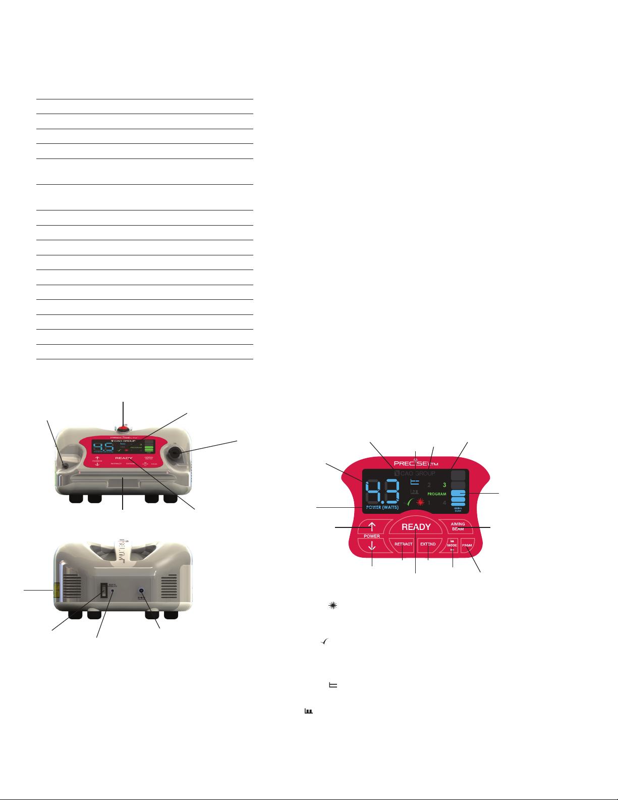
SECTION 2: BEFORE OPERATING YOUR LASER
2.0 CONTENTS
The contents of the shipping container should include
the following:
Precise LTM Complete Kit
(1) Precise® LTM Unit
(1) 20’ Fiber Cartridge
(1) Fiber Stripper Tool
(1) Fiber Cleaver
Package of (20) Disposable Handpiece
(1)
Tips- Straight
Package of (20) Disposable Handpiece
(2)
Tips- 60°
(2) Handpiece- Autoclavable
(1) Laser Key
(1) Wireless Foot Pedal
(1) 9 Volt Lithium Battery
(1) Power Supply
(1) Power Cord
(3) Protective Glasses
(1) Precise LTM Operator’s Manual
(1) Precise LTM Chairside Guide
(1) Danger - Laser in Use Signage
(1) Procedure Guide
a
b
c
d
2.1 REMOVING THE LASER FROM THE PACKAGING
Please do not attempt to unpack the laser and install the various
components without reading this section rst. If you are unsure
about any aspect of the assembly, contact customer care at
(877) 236-4408 or [email protected] for assistance.
It is highly recommended to retain the box the laser arrived in. It
has been designed specically to transport the laser and may be
useful should repairs become necessary in the future.
LASER ASSEMBLY INSTRUCTIONS SUMMARY
1. Attach the laser’s power cord and place the plug into the
wall receptacle.
2. Install foot pedal battery. (See Section 2.2.3)
3. Attach remote interlock, if desired (not required).
4. Check the laser stop button to see that is has been
pressed.
5. Turn on the power switch on the back of the unit.
NOTE: When the power cord is plugged in, the power
switch is turned on, and the laser stop is released, the key
will turn the unit on.
6. Place the key into the key switch receptacle and turn the
key to the right (clockwise). The control console should
light up.
2.1.1 TRANSPORTATION
Precise® lasers are susceptible to misalignment if not handled
properly. The unit should ALWAYS be handled carefully and never
banged, jarred, jolted, dropped, or hit. Do not transport the laser
unless it is completely packaged inside of the box it arrived in.
Failure to properly package the laser can result in damage to the
laser and accessories. When transporting or shipping your laser you
must always disconnect the keys, the AC Power Adapter and ber
from the laser. If you have any questions regarding transportation,
please call your authorized representative or CAO Group, Inc.
4
2
1
3
7
5
7
PROGRAM
KEY
5
AIMING
BEAM
Figu re 1
Figu re 3
6
6
POWER
INCREASE
6
POWER
INCREASE
FIBER
9
8
FIBER
RETRACT
EXTEND
3 & 4
2
READY
KEY
MODE
KEY
The aiming beam control allows for ve (5)
levels of intensity of the aiming beam. Each
bar represents 20% of maximum intensity.
Zero (0) bars indicates the aming beam is
shut off.
6. Working Beam Setting
Indicates the working beam power output
setting. Use the Power Increase or Decrease
key to adjust power settings from 0.5 to 5.0
Watts. Press and hold the desired key to
rapidly change the value.
7. Progam Setting Indicator
Indicates current program mode selected.
Program key will cycle through programs in
a clockwise direction (1-4).
8. Fiber Extend
Press and hold to extend the ber from the
cartridge.
9. Fiber Retract
Press and hold to retract the ber into the
cartridge.
f
j
e
LED DISPLAY AND CONTROL PANEL
1. Laser on Indicator
Illuminates when the foot pedal is depressed.
Indicates that the working beam energy is
g
h
Figu re 2
a. LASER STOP
b. FIBER APERTURE
c. LED DISPLAY
d. KEY SWITCH
e. CONTROL PANEL
f. MAGNETIC HANDPIECE HOLDER
g. POWER/FAN SWITCH
h. REMOTE INTERLOCK CONNECTOR
i. POWER SUPPLY RECEPTACLE
j. WARNING LOGOTYPES
4
i
emitted.
2. Ready Indicator
Illuminates when READY key is pressed. It
will blink for three (3) seconds, then remain
steady. Once it is steady on, the aming
beam can be activated.
3. Continuous Mode
Illuminates when the unit is in Continuous
Mode.
4. Pulse Mode
Illuminates when the unit is in Pulse Mode.
5. Adjustable Aiming Beam
The Precise LTM is actually two lasers in one,
the infrared laser which performs the actual
treatment and a second “laser pointer”
which illuminates red and allows the user to
view where the working beam is directed..
Page 5

2.2 ASSEMBLING THE LASER
2.2.3 Wireless Foot Pedal Battery Installation/Replacement
Each of the following items should be inspected, inserted into the
appropriate receptacle, and when applicable, locked using the
locking hub.
2.2.1 Power Cord Installation
Remove the AC adapter and the AC power cord. Push or plug
the power cord rmly into the adapter. Plug the small adapter
cord into the appropriate receptacle on the back of the laser. AC
adapter cord may not be ush when plugged in. When resistance
is met stop insertion. To prevent power surges due to electrical
storms or spikes in line voltage, we recommend that you use a
power strip with a surge suppressor or unplug the laser when you
are not present. Plug the power cord into a 110 Volt AC outlet
rated at 60 Hz. Be sure to position the equipment such that you
can quickly access and disconnect the power cord connection
from the back of the unit if the need arises.
1. Insert a Philips-head
screwdriver into one of
the screw holding down
the battery cover and
twist counter-clockwise
until the screw is fully
removed. Repeat with
the remaining screw.
2. Push down on one
end of the battery cover
while simultaneously lifting
up on the other end to
remove it.
3. Locate the battery
terminal inside the well
and gently pull the
terminal out. Do not pull
excessively on the wires.
2.2.2 Power/Fan Switch and Key Switch
The Power/Fan Switch for the laser and fan is the rst item you turn
on each day. The switch is located on the rear panel of the laser
near the lower left hand corner. The Key Switch is the major circuit
breaker for your laser. It will be the second item you turn on when
activating the laser each day. Place the laser key into the key
receptacle located near the right-hand side on the front of the
laser. (See Figure 4) Check the key switch by pushing in and turning
the key clockwise, approximately 1/4 of a turn. This is the (ON)
operating position for the key. The fan will start when the power/
fan switch is on and the key is turned. Prior to leaving the ofce,
the laser safety ofcer should check to see that the key switch has
been turned off and the key removed and stored.
2.2.4 Disposable Fiber Cartridge Replacement
A tamper sticker is in place on the ber cartridge. Do not
remove ber cartridge without contacting Customer Care
rst (877-236-4408). Warranty may be voided. After cleared
for removal by Customer Care, read directions thoroughly
before beginning.
Figu re 4 - OFF Pos itio n Figure 5 - ON Po sition
Precise® LTM Remote Interlock
The Precise LTM laser is equipped with a Remote Interlock Jack.
The Remote Interlock Jack is provided so that a clinician may install
the laser in a dedicated laser treatment room such that the laser
will be interlocked with the entrance door of the room. In such
an interlocked installation, the laser would shut off anytime the
door is opened, hypothetically, to protect the person’s eyes who
is entering the room. It is recognized that such installment is not
facilitated nor required in many operatories or clinics. To that end,
1. Turn system off.
Remove the ber from the
handpiece and fully retract
ber into the cartridge.
Place unit upside down
on a hard surface.
the Remote Interlock is available to any practitioner that requires
it. The Remote Interlock Jack is located and clearly labeled on the
rear of the laser. The miniphono jack is wired in the normally closed
position; meaning that no further action is required to operate the
laser without the interlock loop. If the interlock loop is desired you
may purchase the loop from a local electronics store. You need
only to inform the local electronics store that you require a mini
(1/8”) phono jack wired into a normally open momentary switch
and select the switch design that best suits your needs. To install the
loop, install the switch on the door and simply plug the miniphono
jack into the Remote Interlock Jack on the rear of the laser.
4. Remove the 9 volt
lithium battery from its
packaging and attach
the battery to the
terminal.
Note A:
Only use 9 Volt Lithium
batteries; alkaline
batteries are insufcient.
Keep an extra 9
volt Lithium battery.
Replacement will be
required roughly every
100 hours of use.
2. Slide ber cartridge out
and gently place on hard
surface next to the unit.
5. Place the battery in the
well with the connector to
the same side as where
the wire leads emerge
from the housing.
Note B:
Make sure the laser is
completely turned off
before replacing the
battery in the foot pedal.
3. Unscrew the empty
cartridge connector
counterclockwise and
pull straight out. Discard
the empty cartridge.
Continued on next page →
6. Replace the battery
cover and replace the
two screws. Tighten
the screws clockwise.
Be careful not to over
tighten. Let foot pedal
rest at least 1 minute
before use.
Note C:
Place the pedal face
down on a hard clean
surface.
5
Page 6

3. Place the new cartridge
on its side in place of the
empty cartridge. Carefully
remove the dust cap. Do
NOT touch the end of the
connector. Grasp the
metal ring at the base of
the coupling to stabilize
and prevent breakage.
7. Slowly push the cartridge
into the bay until the
outside surface is ush with
the side of the unit. Make
sure the optical ber coil
retracts inside the cartridge
as it is gently slid into place.
4. Gently push the coupling
into the connection while
maintaining your grasp on
the metal ring. Continue
to hold the metal right.
Push the spring loaded
coupling into place and
twist clockwise until locked
into place.
8. Turn on the power to
the laser system. Press
the Extend and Retract
buttons to ensure the
ber is moving properly.
If it does not, gently push
the cartridge into the bay
further.
6. Position the cartridge to
line up with the guide tabs
on the side of the bay.
9. Don’t look directly at the
aiming beam! Make sure
the aiming beam indicator
is at a value other than
zero (0), and then press
the Ready button. DO
NOT press the foot pedal.
The aiming beam should
be visible from the end of
the ber.
2.3.1 Power Requirements
110 -120 VAC ± 10 % at 60 Hz, 1.5 Amps
Frequency Range: 45 - 63 Hz
9 Volt Lithium battery
2.3.2 Heating, Ventilation, and Humidity
The room where the laser is used should have good cooling and
heating system so that the laser can be operated within the
optimum range of 20 - 30ºC (68 - 86ºF). Avoid storing or transporting
the laser in temperatures below 0º Celsius (32º F). Operating and
storage humidity should be 5-95% RH.
2.3.3 Lighting
Overhead lighting and/or dental unit light should provide enough
illumination to allow good operator vision when activating the
laser intra-orally.
2.3.4 Combustible Chemicals and Gases
All gases that are combustible or support combustion and are used
in the operatory area where the laser is in use must be turned off
and ventilated during the procedure. Cleaning supplies or other
ammable chemical compounds should be stored in an area
away from the surgical site in order to avoid possible combustion.
2.3.5 High Speed Vacuum Systems
Plume evacuation is a priority when vaporizing tissues. The clinician
or operator, and their chair-side assistants should keep themselves
and the patient safe by using a high volume vacuum system and
high ltration masks that are suitable for virus and bacterial control.
Note: Never re working
beam if the ber is fully
retracted in cartridge.
2.2.5 Laser Stop Switch
Before activating the laser, rst check the laser stop switch to
ensure it’s locked in the “in” position (see gure 22). The switch is
the red button located on the top of the laser. The button must
be “in” to operate. If the laser stop switch is “out”; engage the
switch by pressing it. The display on the control panel should now
be lighted. To interrupt laser emissions in an emergency, depress
the button again to the “out” position.
Figu re 22 - La ser Stop di sabled (“I N”)Figu re 21 - Laser Sto p enab led (“OUT”)
If you nd that the display is still not operational, check all
attachments, keys and switches to see that they are securely
installed and, that you have an active wall plug for electricity.
(See Troubleshooting Section). If the laser cannot be activated,
please contact Customer Care (877-236-4408) who can help you
troubleshoot.
Note: This is not a power switch.
2.3 FACILITY REQUIREMENTS
In order to insure the safe use of the laser in your facility, please
check to make sure that the proposed location has the following:
6
2.3.6 Access and Visual
Access to the treatment area should allow the dental team to
restrict entry while the laser is in use. There should be a Danger
Laser In Use Safety Sign placed in a designated area adjacent to
the entry into the treatment area. See Figure 42.
SECTION 3: OPERATING YOUR LASER
3.0 SAFETY CONSIDERATIONS BEFORE USING
YOUR LASER
The safe use of the Precise LTM® is the responsibility of the entire
dental team including the doctor and the Laser Safety Ofcer
(LSO) appointed from the dental ofce team. Protocols for the safe
use of lasers have been developed by a combination of medical
and dental professionals working in concert with educators at
the university level, scientists and laser manufacturers. Dental
professionals have had to develop protocols and guidelines
for using the laser on oral soft tissues. Sound judgment and the
concern for patient safety should be the basis of all laser care.
3.0.1 In-Ofce Safety Issues
• Lighting & Ventilation: Always use the Precise LTM in a well lit
and ventilated area. Make certain that chemicals or gases
capable of supporting or causing combustion are not present
when using the laser. Use high volume vacuum to remove the
laser “plume” and provide high ltration masks for all people
including the patient and any family or guests present in the
treatment area during lasing.
•
Safety Eyewear: While using the Precise® LTM laser, doctors,
auxiliary staff, patients, and anyone attending them in the
operatory must wear the laser glasses provided with the
Page 7
Precise LTM system, which is appropriate for use with this type
of device. If additional glasses (part #002-00186) are obtained,
they must have the same specications for wavelength and
optical density as the glasses provided with this equipment.
Never point the laser tip directly at the face, eyes or skin
of anyone while emitting energy. The aiming beam is also
capable of causing eye damage.
•
Test Firing the Laser: Always test-re the Precise LTM prior to
using it intra-orally. Using a power of 1 Watt continuous wave
or less, place the laser in the ready mode. Then, activate
the laser for 1 - 2 seconds while aiming the ber onto a 2 x 2
gauze sponge moistened with water. Do not use alcohol or
any other combustible material to moisten the 2 x 2 gauze
as it may ignite.
•
Fiber Preparations: After cleaving and stripping the ber,
photo-initiation of the ber tip will allow the operator to remove
tissue more rapidly when contact procedures are indicated.
Gingival debris on the tip will retain the heat and it should be
removed. The tip will also begin to blacken and deteriorate
as it retains the heated debris and can break if not removed
by cleaving it. Clean the tip often using a 2 x 2 gauze sponge
moistened with water. Do not use combustible liquids to moisten
the 2 x 2.
•
Danger - Laser In Use Signage: Each operatory where the
Precise LTM is used should have a “Laser In Use” sign placed
at the operatory entrance when a procedure is in progress.
This signage will help to reduce occurences of eye damage
caused by inadvertent exposure to laser energy. See Figure 42.
•
Sharps Disposal and Sponge Removal: Remove cleaved ber
remnants and place them into a sharps container for disposal.
All gauze used for cleanup of lasers and bers should be
disposed of in a bag for contaminated soft products.
•
Plume Evacuation: Use high volume evacuation
suction during procedures to remove laser smoke or
‘plume’ debris. Use masks suitable for viral ltration.
Caution - laser plume may contain viable tissue particulates.
•
Key Switch: When the key switch is in the ON position (turn
clockwise to the right so it is 90 degrees in the vertical [↑]
position), the laser has been enabled and can be activated
while in the READY status. When not in use, insure that the
key has been turned off or that the laser is placed in the
STANDBY status.
• Safety Education: Provide comprehensive safety procedure
training for all ofce personnel and including front ofce staff
in all outside laser courses when possible. Be certain that all
members of the dental team understand how the laser works
and can advise patients as to their safety and advantages
over conventional procedures.
•
Laser Security: To prevent the unauthorized use of the laser
while not in use, the key should be removed from the unit and
maintained by the Laser Safety Ofcer (LSO).
•
Laser Stop Options: Any of these mechanisms can be used to
shut down the emission of laser energy in a real or perceived
emergency.
1. Foot Pedal – remove your foot to stop lasing
2. Engage the laser stop button
3. Key – turn off the key
4. Switch the Power to the off position (O)
5. Power Cord – unplug from the wall outlet
•
Hard Tissue Procedures: The Precise LTM diode is not an
appropriate laser for hard tissue procedures. The diode laser
is attracted to melanin, hemoglobin and to some extent, to
water and oxygenated hemoglobin. Avoid prolonged exposure
of the energy when working in and around the cervical areas
of the tooth. Due to the thin layer of enamel in this area, the
laser’s energy may be absorbed by the hemoglobin in the
pulp and pulpal hyperemia may occur. Extended exposure to
laser energy could lead to pain and possible pulpal necrosis.
3.0.2 Laser Safety Program and Continuing Education
We recommend implementation of a Laser Safety Program
appropriate for your dental ofce. The plan may include the
following:
• Selection of a Laser Safety Ofcer (LSO).
• Minimum Training requirements for users of the laser.
• Laser security against unauthorized use of the laser.
•
Standard operating procedures to regulate the work environment
in order to protect the patient and ofce staff from laser hazards.
The Laser Safety Ofcer (LSO) can be a full or part-time employee
or the laser operator and is responsible for:
• Safe use of a laser.
•
Training of the staff, related training records and laser
performance.
• Perform regular safety checks and prepare the laser for use
on a daily basis.
•
Keep records of any incidents laser failure or adverse effects
and report such incidents as required by law.
•
Assure a medical follow-up has been sought or has occurred
following any adverse incident during treatment.
•
Training of all ofce personnel who are involved with the laser
preparation and use.
• Daily check of the facility and equipment.
•
Test re the laser prior to beginning of each treatment procedure.
For more information on the contents of a Laser Safety Plan, you
can review ANSI Standard Z136.3 for Safe Use of Lasers in Health
Care facilities or TR IEC 60825-8 Guidelines for the Safe Use of
Medical Laser Equipment. The LSO should insure that the operator
and staff attend laser courses taught by qualied laser educators.
Ongoing reviews of laser safety procedures should be a part of
normal ofce routine.
3.0.3 Food and Drug Administration
Manufacturers of products subject to performance standards
under the Federal Food, Drug, and Cosmetic Act, Chapter
V, Subchapter C - Electronic Product Radiation Control are
required to certify compliance with the regulations and furnish
various reports to the Center for Devices and Radiological
Health (CDRH). For medical laser manufacturers, additional
review by the FDA of the safety and effectiveness of the device
is required. Companies who intend to market a medical laser
today must receive authorization from the FDA to permit the
device into commercial distribution. There are two forms of
premarket clearance procedures. The premarket notication
510(k) procedure is principally used for those devices that are
documented to be substantially equivalent to legally marketed
Class I and Class II devices. For new devices not equivalent to
legally marketed devices, a more complex
PMA is required.
7
Page 8

3.0.4 OSHA and its Provisions
Worker safety is the responsibility of the employer and is regulated
by OSHA (Occupational Safety and Health Administration), a
division of the U.S. Department of Labor. OSHA has issued no
specic standard for safe use of lasers but recognizes ANSI standard
Z136.1 as a source for analyzing safety with respect to medical
lasers. For more information see OSHA Technical Manual (TED
1-0.15A) Section III, Chapter 6, 1999. CAO Group, Inc. recommends
implementation of a Laser Safety Program for the safety of your
patients and ofce staff in connection with the use of the Precise®
LTM 5 Watt Soft Tissue Diode Laser.
in use by other devices by adaptive hopping. Since the Precise
LTM wireless transmitters have a much lower power output, it
is highly unlikely that they would “interfere” with higher-power
devices. Even if this were possible, the higher-power devices
would quickly switch to another channel to achieve uninterrupted
operation. The Precise LTM wireless receiver use an entirely different
protocol, and therefore cannot (receive) data from Bluetooth or
Wi-Fi devices. The converse is also true; their protocol methods
are incompatible. Precise LTM diode laser wireless technology
is electronically coded. Each pedal and Precise LTM diode
laser share a UNIQUE SERIAL NUMBER INTERLOCK protocol for
reliable operation:
3.0.5 Statutory Licensure
•
State training requirements for all dental professionals vary and
change from time to time. A prociency certication may be
required prior to using the laser. These courses are usually taught by
members of the Academy of Laser Dentistry who possess instructor
credentials. Check with your state licensing board regarding the
•
applicable requirements for using lasers in dentistry to ensure full
compliance with Federal, State, and local regulations.
•
3.0.6 Wireless Technology
In order to promote efcient use of the radio spectrum in various
global markets the United States Federal Communications
Commission (U.S. FCC) and other international government
agencies have developed technical standards for devices that
are capable of emitting radiofrequency energy when in use – such
as wireless data cards. These products need to receive certain
identication numbers in accordance with the Commission
Equipment Authorization rules prior to marketing in U.S. markets.
The Code of Federal Regulations, Title 47 (47 CFR), Part 15 covers
the rules for the operation of unintentional, intentional or incidental
In summary, the wireless transmitters in the Precise LTM diode laser
have less than 2% of the output power of typical Bluetooth or
Wi-Fi devices, and therefore have no signicant potential as an
interference source. Precise LTM wireless receiver is incompatible
with Bluetooth or Wi-Fi devices and therefore cannot mistakenly
receive data from such devices. Through a unique internal
communication structure, and strict verication of all incoming
data, nothing activates a Precise LTM diode laser except the
wireless pedal which it is paired with via electronic code.
radiators. Any electrical or electronic devices incorporating digital
circuitry and operating with an oscillator or clock speed of greater
than 9kHz requires approval to this rule. There are various types of
FCC Part 15 approvals, depending on the nature of the product
and its intended use. In Canada, IC-RSS 210 (Radio Standards
Specication) sets out the requirements for license exempt low-
power intentional radiators. This standard is very closely harmonized
in terms of permitted frequencies, types of operation, and other
technical requirements to the FCC requirements, but a separate
certication application is required for Canada. In the European
3.0.8 American National Standards Institute (ANSI) -
Safety Standards
ANSI is a non-governmental, non-prot agency that has established
guidelines and safety standards for the use of lasers and other
electro-optics. The provisions of ANSI Z 136.3 outlines standards for
lasers used in dentistry and the assessment of laser risks. ANSI also
establishes guidelines for safety eyewear and classies all lasers
based on their potential for damage to eyes or tissue. See table
1 for NOHD requirements.
Community, compliance with several safety directives and testing
to EN 300 328, EN 60950 and EN 301 489 is required for this type of
device. The manufacturer is required to provide a
Declaration of Conformity as evidence of its compliance with the
various regulatory requirements.
3.0.7 Precise® LTM Wireless Frequency
The 2.4GHz frequency is very popular for networks and other
wireless devices that share similar technology like Bluethooth
cell phones, Wi-Fi® devices, wireless networks, cordless phones,
CAD/CAM machines, wireless video senders, even microwave
ovens. The nature of spread-spectrum modulation in the 2.4
Ghz frequency means that a multitude of devices can co-exist
in the same 2.4 GHz spectrum (as should be obvious, since
many devices use 2.4 GHz and operate well on a daily basis).
Bluetooth and Wi-Fi devices use multiple channels, recovering
data reliably out of noise in the 2.4 GHz spectrum. They will hop
around strong interference, and quickly re-try for uninterrupted
operation -- and can even avoid channels or areas of the band
3.1 STARTUP AND SYSTEM CHECK
3.1.1 Selecting the Treatment Center
The laser should be placed in an area with good ventilation and
lighting. The electrical service required is a 110 Volt A/C outlet - 60
Hz. The area where the laser is placed should be free of standing
water. Combustible gases or those that support combustion should
®
be turned off and all ammable materials or chemical stored in
the area should be removed.
3.1.2 Checking the Foot Pedal Installation
It is recommended to use a 9 Volt Lithium battery to power
the cordless foot pedal. This type of battery has been
tested to last for over 100 hours of foot pedal operation.
Note: A 9 Volt Alkaline battery may be used, however the
life expectancy of an Alkaline battery is less than 35 hours of
operating time.
A Precise LTM pedal communicates with only one Precise
LTM diode laser; there is 2-way electronic code which must
be veried for every transmission and acknowledge. The
pedal and laser unit are interlocked to only each other’s
electronic codes.
If data from another Precise LTM pedal is ever received,
embedded verication measures ensure that it is always
ignored and discarded.
If data were ever received from another wireless device with
a compatible protocol scheme (2.4GHz frequency), it would
immediately be discarded in the same way.
8
Page 9

3.1.3 Checking the Key Activation and Control Panel Display
3.2 OPERATING YOUR LASER
Turn the Key Switch on the front of the laser to the “On” position by
turning it approximately 1/4 turn to the right (clockwise). The control
panel should light up and show the laser is in Standby Mode.
3.2.1 Before Beginning Procedures
Examine the ber tip to insure that you have not created a ber
tip shard during the cleaving process. The shard (Fig 23) can act
3.1.4 Checking the Laser Stop Button
Check the Laser Stop Switch to see that it has not been pressed.
If it has, release it by pressing it slightly. See section 2.2.5.
like a miniature scalpel and cause damage while diffusing the
light beam and lowering the laser’s power (See section 4.0.7 for
cleaving procedure). Depress the “Ready” button and the aiming
beam can light after 3 seconds. Review your power and mode
3.1.5 Checking the Disposable Fiber Cartridge
requirements and then depress the mode button to select either
Do not sever tamper sticker without contacting Customer Care rst.
Depress the extend/retract button on the control panel to see that
it is functioning properly. After checking the ber cartridge power,
extend approximately 3 feet (1 meter) of ber. Strip, cleave and
disinfect the ber; attach the handpiece and tip (see section 4).
Press the Ready button to activate the aiming beam. Aiming beam
should be set above zero (0). If aiming beam still is not illuminated
call Customer Care at (877) 236-4408 for further troubleshooting
3.2.2 During Procedures
•
assistance. Do not depress the extend and retract button during
laser operation.
3.1.6 Setting Modes
•
The Precise® LTM features two modes. Pulse mode allows some
cooling of the tissue and id designated by a (insert pulse mode
symbol here). Continuous mode transmits laser energy without
interruption and is designated by (insert continuous mode symbol
here). Review your power and mode requirements and then
depress the mode button to select either Continuous or Pulse
mode (see section 3.2.2 for further details) .
3.1.7 Setting Power
Select your power by pressing the up or down arrow until you have
reached the desired wattage. Beginning with a low of 0.5 Watts,
•
the power increases in increments of 100 mW up to a maximum
of 5.0 Watts (Continuous Mode). By holding the up or down arrow,
you can have an uninterrupted progression until you reach your
desired power.
3.1.8 Setting Aiming Beam
• Continuous Mode ( ): In setting up the laser while in the
The aiming beam can be turned on and off by pressing the
aiming beam button on the laser control panel. Press this button to
progressively increase the aiming beam intensity from zero (0) (off)
to full intensity. Press the key once more to cycle back to zero (0).
Each bar represents approximately 20% of the aiming beam output.
Note: Adjusting the intensity of the aiming beam has no effect on
the output power of the working laser.
3.1.9 Programming your Precise LTM
You are able to easily set four (4) different combinations of Power,
Mode and Aiming Beam Intensity. The initial Precise factory setting
is 1.4 W Power + Continuous Mode + 80% Aiming Beam Intensity.
To set your programs, push the Program key to display one of the
program numbers. Choose the desired Power level, the desired
Mode and the desired Aiming Beam Intensity. Press the READY
•
button – your settings have been saved. Repeat for each of the
four programs. You may change your settings as often as you like.
The settings saved into the four programs will be retained even if
the laser is turned off.
NOTE: Whenever your press the READY button, the settings
displayed on the unit will be saved into the unit’s memory for the
program setting shown.
or mode.
Figu re 23 - Fib er with a shar d (a bad cle ave)
Test re the laser outside the mouth by activating the laser
into a 2 x 2 gauze sponge that has been moistented with
water to prevent combustion. Do not use ammable liquids
to wet the sponge.
Standby and Ready Status: If the laser is powered on the status
of the laser will be in Standby which is a non-active status. The
laser will not emit energy while in Standby, even if you depress
the foot pedal. On the top-center of the control panel you
will see the “Ready” button (See Figure 3). Press this button to
place the unit into ready status. When this button is pressed
whatever settings are displayed on the unit will be saved into
the unit’s memory for the program setting shown. The settings
saved into the four programs will be retained even if the laser
is turned off. The laser will now be ready to emit energy as you
depress the foot pedal.
Depress the foot pedal and make short feather like quick
brush strokes at the lowest power that you can to remove
the target tissues (with initiated tip see section 4.0.8) while
lightly contacting it. It is recommended to complete a training
course and practice on pigmented foods such as hot dogs
or tomatoes before attempting a procedure on a patient.
mode, you will deliver the amount of energy in Joules in one
second equal to the value indicated in the working beam
setting, i.e., set the laser for 2 Watts and while activated the
laser will deliver 2 Joules per second as long as you have the
foot pedal depressed. The mode is generally the fastest way
to ablate tissues but heat can build up and cause collateral
damage to the target and adjacent tissues. Cool the tissues
being lased by using periodic blast of air from a triplex syringe
and high speed suction. You may use water to cool in areas
where there is prolonged exposure to the laser’s beam. Avoid
using the air syringe when you have an opening in soft tissue
adjacent to or within the surgery site. An air embolism may
occur as a result of air captured within the tissue during the
cooling process.
Pulse Mode( ): Pulsing the laser energy will allow some
cooling of the tissue in-between emissions of energy. The
“duty cycle” is the percentage of the time in each second
that the laser is emitting energy. The pulses per second, the
duty cycle and the energy intensity per pulse will determine
your average power. In the pulsed mode, the Precise LTM is
programmed to deliver 10 pulses per second with each pulse
lasting for 0.05 seconds. The duty cycle is set for 50% so you
9
Page 10

will have 1 energy pulse followed with 1 period of rest with no
energy between each pulse.
The result will be an average energy per second that will be
50% of what you have set the laser for. Therefore, when using
pulsed energy, you will have to adjust your power upward in
order to achieve the same rate of work as the same power
set in. Two Watts of Pulsed energy will be the same average
power output as 1 Watt. Remove your foot from the foot pedal
and use a clean 2 x 2 gauze sponge moistened with water to
remove debris from the ber tip. Do not use ammable liquids
to wet the sponge. Place the laser in Standby mode by turning
“Ready” off until you are ready to start another procedure.
Tissue Responses to Laser Energy: Maximum results will be
achieved by regulating the power and the speed that the
operator moves the ber tip. Tissue charring is an undesirable
after effect of too much power or the tip moving too slowly.
Always use the least amount of power necessary to complete
your procedure. The ideal tissue response will show little or
no discoloration after lasing and there will be less residual
damage and faster healing. Avoid penetrating or damaging
the periosteum and do not use the laser on alveolar bone.
Because the laser energy is attracted to melanin and hemoglobin,
power must be reduced when treating patients with darker
soft tissue. Always begin lasing with the lowest power you can
use to remove or modify the target tissues. Avoid damage to
the gingival sulcus by moving the ber tip quickly and using
low power settings. Check to make sure you have a good
cleave of the ber so that no shard is present on the tip. A
shard may act as a miniature scalpel and damage the small
blood vessels, thus preventing hemostasis and coagulation.
Additionally, diode lasers cut differently than other tools.
Diode lasers are end cutting meaning only the very tip cuts.
Use just the very tip of an initiated (see section 4.0.8) Precise®
LTM ber in light brush strokes in order to cut. Do not drag as
with a scalpel or electrosurge. This technique is very efcient,
damages less tissue in addition to increasing ATP production,
resulting in less pain and reduced healing time.
3.2.3 After Each Procedure
•
Cleave used ber tip and discard in suitable bio-waste sharps
disposal.
•
Wipe the outside of the ber using a disinfectant or sterilization
solution (see section 4.1.1) and then retract the ber by
depressing the RETRACT button on the control panel. Do not
retract the distal end of the ber into the cartridge.
•
Turn the key to the off position if another procedure isn’t
planned and remove key.
•
Record the Power setting(s), mode, and Total Lasing Times
used for each procedure in the patient’s chart.
Example:
Patient Name Mary Jones
Procedure Gingivectomy #6 and #7
#6 Lasing time
#7 Lasing time
10
90 seconds @ 2.0 Watts
air cooled
60 seconds @ 1.5 Watts
air/water spray
SECTION 4: PREPARATIONS, CARE,
AND MAINTENANCE
The ber optic element of a laser is responsible for carrying the
light from the diode array to the tissue being treated. Precise
laser dental laser bers are usually made of a quartz and silica
combination. Be advised about the potential hazards when
inserting, steeply bending or improperly securing the ber optics
to the frame (chassis).
Laser radiation exposure may occur in these instances which
could be harmful to yourself, your staff, and your patient. Special
care should be taken not to break or snap the ber. As the Aiming
Beam passes down the same delivery system as the Working
Beam, it provides a good method of checking for integrity of
the delivery system. If the aiming beam spot is not present at
the distal end of the delivery system, its intensity is reduced or it
looks diffused, this is a possible indication of a damaged or an
improperly working delivery system. Call Customer Care in these
instances for assistance.
4.0 DISPOSABLE FIBER CARTRIDGE
The ber cartridge is a removable assembly with a plug-in capability
that provides power for the internal retraction device. This cartridge
is disposable after all ber has been used. This cartridge is not
autoclavable. The ber cartridge contains approximately 20’ (6
meters +) and is wound onto a spool. Call Customer care (877236-4408) before replacement and/or severing the tamper sticker
on the bottom of the ber cartridge.
4.0.1 Replacing the Fiber Cartridge
A white or black mark on the ber indicates 18” of ber remaining
on the cartridge. At this point, a new ber cartridge should be
ordered. See section 2.2.4 for instructions on replacing the ber
cartridge. The spent ber cartridge can be thrown away.
Note: Retain the ber end cap. DO NOT discard the end cap.
4.0.2 Fiber Preparation
Prepare the ber for use by depressing the EXTEND button on
the control panel (see gure 3). Place a disposable tip onto the
handpiece. Extend 3 - 4’ of ber and feed it through the ber
locking collar at the base of the handpiece after loosening
the collar by twisting it counterclockwise (just till loose do not
full disassemble). If using curved tips gently straighten while
feeding ber until it extends about 1’ beyond the distal end of the
handpiece. Tighten the locking collar by twisting clockwise until
resistance is met. Strip, cleave and disinfect the ber (see sections
4.0.6 - 4.0.9). Loosen locking mechanism again and pull ber back
until 1-2 mm of cladding is visible beyond the tip.
Do not continue to use the uncovered ber once you have
observed that it has a blackened appearance that is greater in
length than 2 - 4 mm from the previous cleave spot. The protein
debris of gingival tissue accumulates on the tip during surgery and
retains extreme heat that can cause rapid tip deterioration and
subsequent breakage.
This is especially important when using the laser for periodontal
pocket debridement. During surgery, clean the tip often using a
2 x 2 sponge moistened with water. Do not use alcohol or other
combustible liquids to moisten the 2 x 2 gauze sponge and do not
use the sponge while the tip is hot.
Page 11
Always use a cold disinfectant solution like BIREX® or CIDEX® to
wipe off the ber jacket before retracting the ber. The ber can
be advanced or retracted by depressing the RETRACT and EXTEND
buttons on the front control panel.
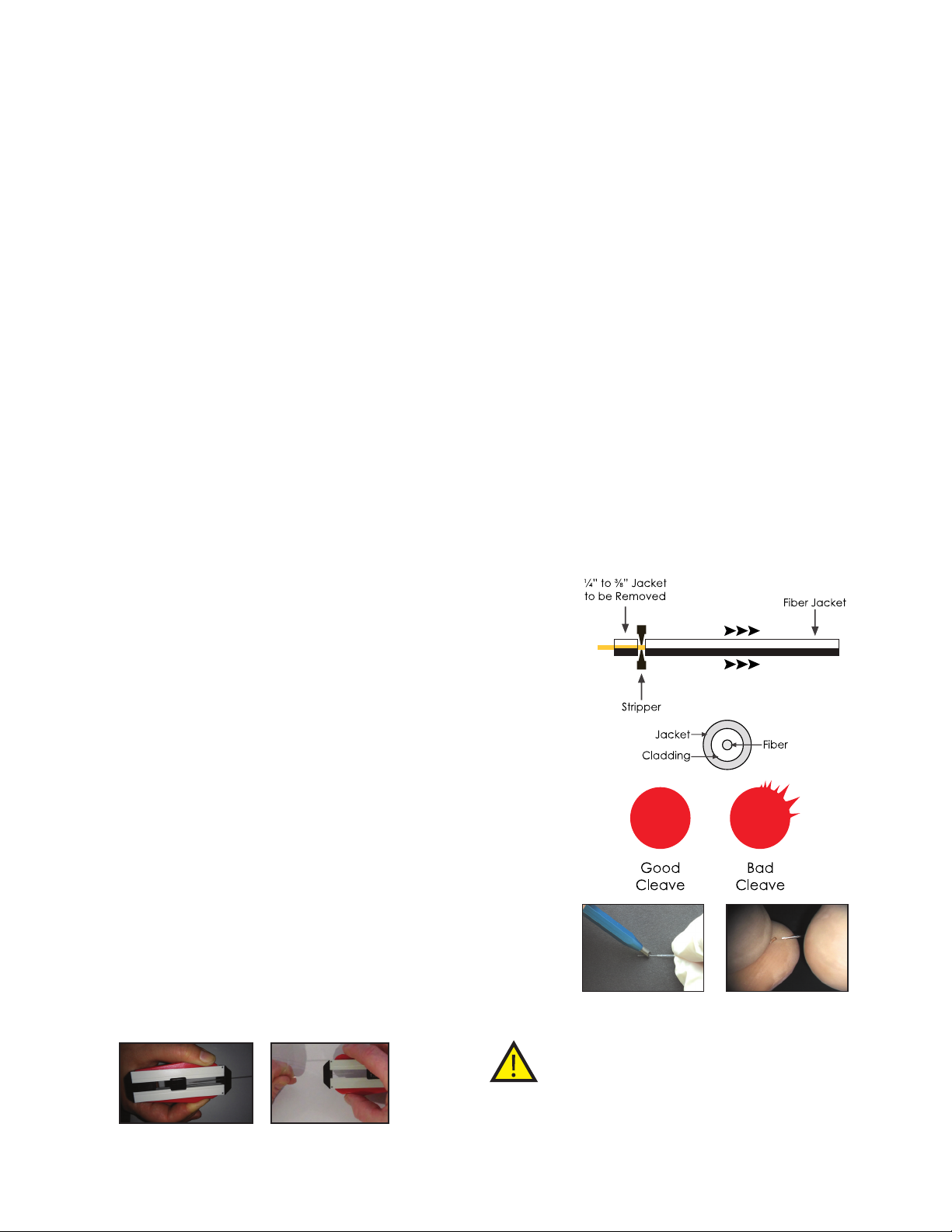
4.0.7 Cleaving the Fiber
Between patients or when the ber deteriorates it is important
to cleave the ber. As the ber tip deteriorates, it is more likely
to fracture and could fall into the sulcus or a deep periodontal
pocket. To avoid this problem, it is prudent to periodically “cleave”
The ber itself has three components:
• Jacket
• Cladding
the discolored tip once it has become black 3-4 mm down the
shaft of the ber. A cleave is made after stripping off the jacket
to expose approximately ¼” - ⅜” of bare ber. (See Figure 27).
• 400 micron quartz/silica ber
Cleave at a point approximately ½” (8 - 10 mm) from the site of
4.0.3 Jacket
The Precise® LTM features a clear protective cover surrounding
the ber made of a synthetic material. This jacket protects the
ber from damage and microorganisms from making contact
with the ber.
the previous cleave so that there is no visible discoloration of the
tip. The operator should place their index nger at the spot of the
proposed cleave so as to stabilize the ber. Using the pen style
cleaver, draw the cleave blade across the top of the ber with
enough pressure to”score” the ber. (See Figure 30).
Grasp the ber with the thumb and index ngers ¼” – ½” on either
4.0.4 Cladding
This is the thin material in between the outside of the quartz/silica
side of the score mark. Apply gentle but rm pressure to cleave
the ber. (See Figure 31).
ber and the jacket. It is used to block the lateral escape of laser
energy as it traverses the ber. During stripping, you may “nick”
the cladding and you will likely see the red aiming beam light as
it escape the site of the damage. This is not a danger if all people
in the area have the appropriate safety eyewear. Simply cleave
and strip beyond the damage.
After you have cleaved the ber, point it perpendicular to a white
piece of paper and place the laser in READY mode. Hold the tip
approximately ½” from the paper and you should see a near
perfect circle of red light. If you have a large comet effect
radiating from the circle, you have not obtained a good cleave.
(See Figure 29). If the circle has just a small comet effect, it will
4.0.5 Quartz/Silica Fiber
The ber is fairly exible but can be broken if bent into a small
probably work. Always dispose of the ber tip remnants in the
“Sharps” container immediately after cleaving the ber.
circle or bent at an angle of 90 degrees. The cladding will burn
as protein from the gingiva accumulates on the ber and will
deteriorate the tip of the ber. It can fracture if not cleaved once
the blackened area has reached 3 - 4 mm. Stop lasing and wipe
off the tip regularly as you work to avoid accumulation of protein
debris. Use water on a 2 X 2 gauze sponge to clean the tip. Do not
use ammable materials like alcohol products when cleaning a
hot tip. Dispose of all small ber remnants after you have cleaved
the ber. They should be kept in a small box with a lid until they
can be properly disposed of in the “sharps” container.
4.0.6 Stripping the Fiber
The ber’s jacket is removed using a “stripper”. Between each
patient and once a ber tip is initiated and begins retaining
debris from the tissues during lasing, you will get a deterioration
of the ber tip. When you have a blackened tip that extends 3 - 4
mm up the ber shaft, it is time to cleave the ber and strip the
jacket to prepare for the next procedure or patient. Begin by
selecting enough jacket so that when it is removed, you will have
approximately ⅜” of bare ber exposed.
Figu re 27 - Adjustable
Fibe r Stripping To ol
Figu re 28 - Adjustable
Fibe r Stripping To ol
Figu re 29 - Lase r prole
after cleaving.
Use the measurement guide and place the end of the ber in the
stripper. Firmly grasp the adjacent ber 2-4” from the portion fed
into the stripper between your thumb nail and index nger. (See
Figure 24). Grasp the ber with the stripper by applying pressure
to the handles. With a slow steady force, remove the jacket by
pulling the ber away from the stripper. (See Figure 25).
Figu re 24 - Adj ustabl e Fiber
Stripping Tool
Figu re 25 - Remove ¼” to ⅜” of
the jac ket with s trip per tool
Figu re 30 - Make o ne pass
using l ight but stead y pressure
Figu re 31 - Break t he ber
agai nst the c leave
Always dispose of the ber tip remnants in the “Sharps”
container immediately after cleaving the ber.
4.0.8 Initiating the Fiber
Once successfully cleaved, prepare to cut soft-tissue. The tip of
the ber can be prepared to retain heat by introducing it to a
11
Page 12
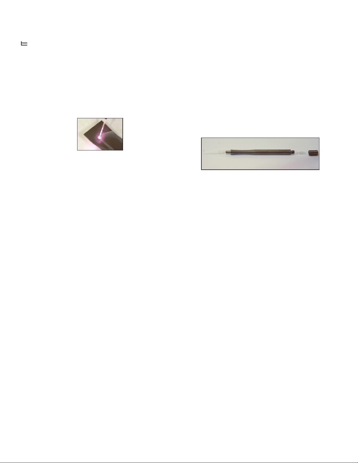
dark pigmented material like ink, blood or cork. The easiest way to
prepare the tip is to lightly move the at surface of the tip across
a piece of articulating paper or cork at about 1 Watt continuous
. The tip will retain the ink and the ink will make the tip glow a
yellow/white color if you exceed 1 - 2 seconds while in contact
with the paper (See Figure 32). Prolonged heating will accelerate
the deterioration of the tip.
Alternatively, you may purchase a calibrated hand-held power
meter approved for use with 810 nm devices to check power
output. The laser should be set at 1, 3, and 5 Watts with output
checked at each level. The output display should be within 20%
of the meter reading. If not, recleave the ber and re-check. If
the output display is still outside the 20% tolerance, return the
unit to the manufacturer for recalibration. Call Customer Care
at (877) 236-4408 for details. There are no methods available for
4.0.9 Fiber Disinfection
The ber and spool remain in the ber cartridge and are not
autoclavable. Once stripped, cleaved and initiated, the tip will
the user to adjust the calibration of the unit and the unit must not
be adjusted, altered, or disassembled by the user for any reason.
Warranty may be voided.
reach temperatures of several hundred degrees centigrade, thus,
as the laser emits energy, it will rid the tip of pathogens.
4.1.3 Handpiece Preparation
The Precise® LTM handpiece is designed for easy assembly and
then sterilization after each patient.
Figu re 32 - Move th e tip lef t
or rig ht while lig htly touchin g
the paper
Additionally, the tip can transfer heat up the shaft of the ber to the
edge of the jacket which may melt slightly. After your procedure,
always cleave the blackened tip and damaged jacket. Wipe
the jacket down using BIREX® CIDEX® or a comparable product
that can disinfect the jacket. Dry the jacket using a clean 2 x 2
The handpiece has four (4) components:
sponge prior to retracting the ber into the ber cartridge. Also
see section 6.0.
a. Fiber locking cap (See Figure 33)
b. Plastic collet - located inside ber locking cap (See Figure 34)
c. Body (See Figure 35)
d. Disposable tip - one time use only; not autoclavable (See
4.1 LASER MAINTENANCE
4.1.1 Laser Chassis Disinfection
The exterior of the laser should be cleaned using a liquid
disinfectant similar to BIREX® or CIDEX®. Do not spray the disinfectant
directly on the chassis. Apply with a gauze sponge or wipe. Do
not use abrasive materials or large amounts of liquid to clean
the system. Place a barrier material such as paralm® or other
temporary self adhesive clear plastic sheeting over the control
panel and LED screen prior to treating the next patient.
4.1.2 Calibration
The Precise® LTM Laser uses solid-state circuitry to continuously
monitor the power output and adjusts the power supplied to the
laser module to keep the output consistent with the user dened
setting. If output levels are more than ± 20% of the set value, the
unit is designed to shut down power to the laser, and an audible
alarm will sound. If this happens, the unit should be turned off and
allowed to sit for 5 minutes and turned on again. If the laser then
boots without beeping, the microprocessor has been able to make
operational adjustments and the unit will perform its functions.
If, upon restart, the unit continues to beep, the unit will need to be
sent in for adjustment by CAO Group, Inc., Service Department. We
suggest that your practice establish an internal calibration program
for your laser. Recalibration is recommended at a minimum of
once per year based on average usage.
Assemble the handpiece with plastic collet, Fiber Locking Cap
and disposable tip in place (see gure 37); only lightly tighten the
Locking Cap onto the handpiece body. Extend the ber about 3-4’
from the Precise unit. Slide the end of the ber through the Fiber
Locking Cap, through the handpiece and out the disposable tip so
that about 1’of ber extends out of the handpiece. Firmly tighten
the Fiber Locking Cap so that the ber is held securely in place.
Now the ber can be prepared for lasing (Section 4.0.2 – 4.0.9). The
Precise® LTM uses an autoclavable stainless steel handpiece that
should be sterilized after every patient. Clean the handpiece with
warm soapy water; rinse thoroughly; disassemble; place all three
disassembled parts in an autoclavable bag, and then autoclave
it accordingly. Set the autoclave for 250°F (121°C), at least 18
psi (124 kPa), and run for 30 minutes, followed by 30 minutes of
dry time (gravity cycle method). Note: Do not re working laser if
handpiece is not properly attached to ber.
4.1.4 Disposable Tips
The disposable tips are sold in two (2) different degrees of access
for optimal use within ber specications, straight and 60° curved.
Do not attempt usage of tips not manufactured by CAO. Doing
so may cause undue stress damaging the ber.
Note: Disposable tips are single use, not autoclavable.
SECTION 5: LABELS, SIGNS, WARNINGS, AND
Recalibration may be performed by the manufacturer by
returning the unit. Call Customer Care at (877) 236-4408 for details.
12
INFORMATION
Figu re 37 - Handpiece Assembly
Figure 36)
Page 13
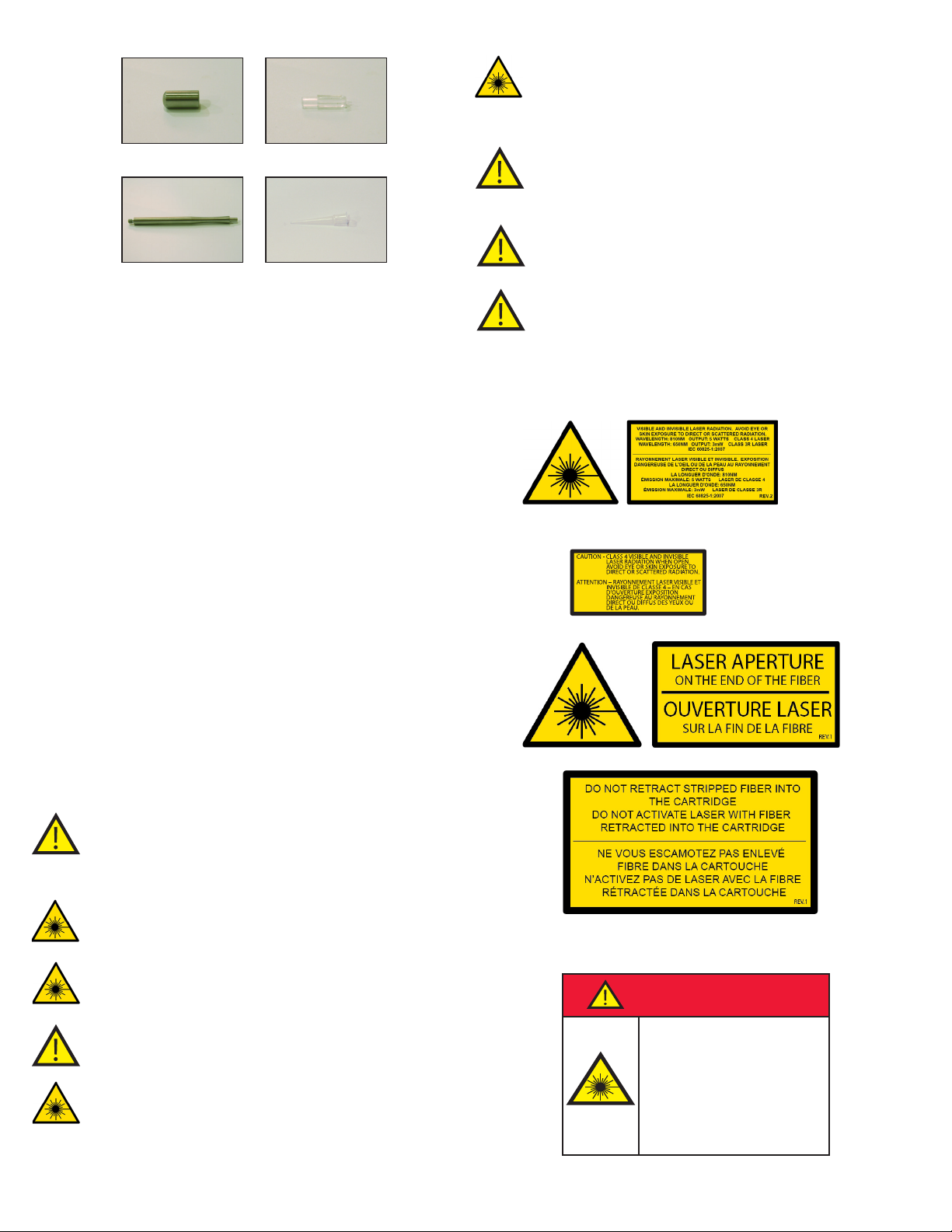
5.3.6 Use of controls, adjustments or performance of
002-00034 Rev.C
DANGER
Class 4 Laser
Controlled Area
Avoid eye or skin exposure to
direct or scattered radiation.
Do not enter when door is closed.
Laser eye protection required: OD≥4@810nm
AlGaAs Diode Laser, 810nm
5 Watts maximum power
Laser Safety Officer _____________________________Ext. ___________
ANSI Z136.1:2014
OPERATORY SIGN
FOR 5W 810NM DIODE LASER
PRECISE LTM REAR WARNING LABEL
procedures other than those specied herein may result
in hazardous radiation exposure. Any misuse is considered
abuse of the product.
Figu re 33 - Fi ber loc king cap Figu re 34 - Plastic collet
Figu re 35 - Body Figu re 36 - Dis posable st raigh t
tip (60 ° angle dis posab le tip
also available)
5.0 FEDERAL COMPLIANCE
The Precise LTM has been designed to the latest safety standards
applicable to medical lasers in the U.S. and Canada, including IEC
60825, IEC 60601-2-22, and IEC 60601-1. This laser is also designed to
meet the construction and performance requirements of the Food
and Drug Administration’s Laser Performance Standard (21 CFR
1040.10 and 1040.11). The laser has also been certied and tested
according to the telecommunications regulations for the US (FCC
Part 15). Various labels are included on the laser and the wireless
footswitch as evidence of conformity to these requirements. The
labels on the unit are required under these standards for safety
purposes and should not be removed. Please review all labels
prior to using the laser. (See Figures 38 through 47). Installation and
operation of this device should be made consistent with CAN/
CSA-Z386-08: Laser safety in health care facilities.
5.3.7 Do not use system if there is any visible damage to
the system, including, but not limited to, cracks, wear, or
damage.
5.3.8 Keep system away from liquids to prevent electrical
shock and damage. Stop and power off system if exposed
to liquids.
5.3.9 Do not use system in an oxygen rich environment to
avoid risk of re.
5.3.10 Consult local services to learn how to properly
dispose/recycle the system.
Figu re 38 - Labe l required un der FDA laser n otice 50
5.1 DANGER LASER IN USE
Each treatment area should have a “Laser In Use” warning sign
posted at the entrance to the treatment area. This signage serves
to warn people to not enter the treatment area without proper
safety eyewear and protective clothing when the laser is in use.
(See Figure 42)
5.2 LASER CLASSIFICATIONS
Class 4 Laser Product (treatment laser): 810 nm, 5 Watt
Aiming Beam Laser: 630 – 660 nm, 2 mW
5.3 CAUTIONS
5.3.1 Changes or modications not expressly approved
by CAO Group could void the user’s authority to operate
the equipment and lead to unexpected laser exposure or
electrical shock.
5.3.2 Laser Radiation – Avoid exposure to the face, eyes, or
skin from direct or scattered radiation.
5.3.3 This product contains no user serviceable components
within the chassis. Visible and invisible radiation may be
present when the cover is removed.
5.3.4 U.S. Federal law restricts the device to sale by or on the
order of a licensed professional.
REV.1
Figu re 39 - Labe l requi red under FDA la ser notice 50
Figu re 40 - Las er Ape rtu re labe l
Figu re 41 - Fibe r Cartrid ge Caution Lab el
5.3.5 Eyewear that protects your eyes from wavelengths other
than 810 nm do not provide proper protection for use with this
laser. Damage to the retina or corneal may be irreparable if
exposed to direct, reected or scattered radiation.
Figu re 42 - Dan ger - Laser sig nage
13
Page 14
5.3.11 Not indicated for patients taking Accutane (Isotretinoin)
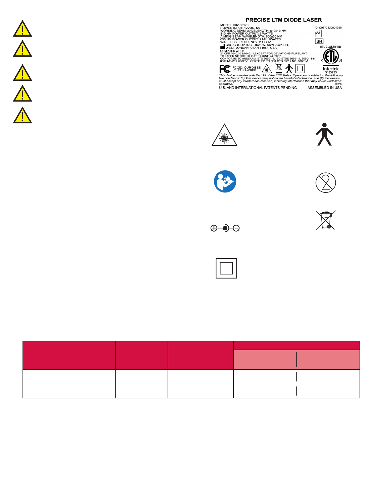
CLASS II LOGO
currently or within the last 6 months.
5.3.12 Use of this device is not recommended for patients who
suffer from light-induced seizures.
5.3.13 Use of this device on pregnant women has not been
studied. Avoid usage on pregnant women.
5.3.14 Do not use this device for procedures other than those
proscribed in this manual. See Section 9.
5.3.15 Make sure the disposable tip is fully seated onto the
handpiece before continuing with the procedure.
5.4 NOMINAL OCULAR HAZARD DISTANCE (NOHD)
(NOHD) Nominal Ocular Hazard Distance – The minimum distance
a person without appropriate eye protection must maintain.
(MPE) The highest level of laser radiation a person may be exposed
to without hazardous effects or adverse biological changes in
the eyes or skin.
(NHZ) The area a laser source is within that exceeds the exposure
level of MPE.
The NOHD is not to exceed the MPE. The outer limit of the NHZ is
the NOHD. Eye protection within the NHZ is mandatory. See table
1 for the NOHD.
NOTE: This equipment has been tested and found to comply with
the limits for a Class A digital device, pursuant to Part 15 of the FCC
Rules. These limits are designed to provide reasonable protection
against harmful interference when the equipment is operated
in a commercial environment. This equipment generates, uses,
and can radiate radio frequency energy and, if not installed
and used in accordance with the instruction manual, may cause
harmful interference to radio communications. (Operation of
this equipment in a residential area is likely to cause harmful
interference. Any required correction of the interference shall be
at the user’s own expense).
Figu re 43 - Rati ng label with s erial num ber
Figu re 44 - CAUT ION - Laser Em itti ng Devic e; Class 4 L aser Figu re 45 - Type B A ppli ed Parts
Figu re 46 - ATT ENTI ON -- Review Ope rator’s
Manua l Prior To Use
12VDC 5A
Figu re 48 - Rated F or 12VDC, 5A
Figu re 50 - Cla ss ll Electr ical Device
Figu re 47 - Do Not Re use
Figu re 49 - Dis pose of electro nics
waste in a r espon sible mann er
NOHD (inches)
SOURCE OF RADIATION MPE (mW/cm2) DIVERGENCE ANGLE
(DEGREES)
No Eyewear
(i nches/cm)
With Eyewear (OD=4)
(inches/cm)
Fiber Optic Devices 1.66 9 154/392 1.54/3.92
Reection from Tissue 1.66 N/A 0.04/0.12 0.0004/0.0012
Table 1 - Nominal Ocular Hazard Distance (NOHD) for various viewing conditions while wearing eye protection.
Assumptions: Maximum Laser Power = 5 Watts, Direct Viewing Angle = 0°;
Reectance Viewing Angle = 20°; Reectance Coefcient of Tissue = 0.001
14
Page 15
SECTION 6: SERVICING
6.0 LIMITED WARRANTY
®
The Precise
LTM Diode Laser is warranted against defective materials and workmanship for a period of two (2) years from the date of
purchase; six (6) months for the ber (excluding consumption) and cartridge. Warranted equipment will be repaired or replaced, at CAO’s
discretion, if returned prepaid to our factory. This warranty does not cover damage to the Precise LTM Diode Laser unit or components
caused by accident, misuse or being tampered with. This warranty does not include labor, postage or delivery charges. This warranty does
not apply to the external nish of the console, handpiece, ber, power cord, foot pedal. CAO Group, Inc. reserves the right to make changes
in design or to modify such previously manufactured products.
ALL RELATED ACCESSORIES USED IN CONJUNCTION WITH THE PRODUCTS INCLUDING BUT NOT LIMITED TO HANDPIECE(S), CLEAVER, FIBER
STRIPPER, POWER SUPPLY, POWER CORD AND PROTECTIVE EYEWEAR, ARE WARRANTIED FOR NINETY (90) DAYS AGAINST MANUFACTURING
DEFECTS. DAMAGE OCCURED OUTSIDE OF MANUFACTURING DEFECTS ARE NOT COVERED BY THIS LIMITED WARRANTY. DISPOSABLE OR
CONSUMABLE ITEMS (E.G. DISPOSABLE TIPS, ETC.) ARE NOT COVERED BY THIS LIMITED WARRANTY.
THIS WARRANTY WILL BE VOIDED IF THE USER ATTEMPTS TO SERVICE THE EQUIPMENT OR IF SERVICE IS PERFORMED BY PERSONS WHO ARE NOT
TRAINED OR AUTHORIZED TO DO SO BY CAO GROUP, INC. IF THE UNIT IS FOUND TO BE DEFECTIVE WITHIN THE PERIOD SPECIFIED ABOVE AFTER
EXAMINATION BY AN AUTHORIZED SERVICE REPRESENTATIVE OR CAO GROUP, INC. AND THE FAILURE WAS DUE TO DEFECTIVE MATERIALS AND/
OR WORKMANSHIP, CAO GROUP, INC. WILL REPAIR, OR, AT ITS OPTION, REPLACE THE DEFECTIVE PARTS WITHOUT CHARGE. CAO GROUP, INC.
RESERVES THE RIGHT TO MAKE SUCH AN EXAMINATION AND TO MAKE NECESSARY REPAIR/REPLACEMENT IN ITS OWN FACTORY OR AT ANY
AUTHORIZED REPAIR STATION. IN THE EVENT THE USER DOES NOT COOPERATE WITH CAO GROUP, INC. IN PROVIDING SERVICE, YOU RELEASE
CAO GROUP, INC. FROM ALL LIABILITIES WITH RESPECT TO WARRANTYING ANY EQUIPMENT OR ACCESSORIES. CAO GROUP, INC. WILL NOT
BE RESPONSIBLE OR OBLIGATED TO THE PURCHASER/USER FOR LOSS OF REVENUES INCURRED BY THE PURCHASER/USER DUE TO THE PRODUCT
REQUIRING SERVICE. IN ORDER TO RECEIVE WARRANTY SERVICE, PRECISE LASERS MUST BE SHIPPED TO CAO GROUP, INC. IN ITS ORIGINAL
TRANSPORTATION BOX. THERE ARE NO OTHER AGREEMENTS, GUARANTEES OR WARRANTIES ORAL OR WRITTEN, EXPRESSED OR IMPLIED. YOU
ARE REQUIRED TO READ THE OPERATING INSTRUCTIONS MANUAL PRIOR TO USE OF THE PRODUCTS AND YOU ASSUME ALL RISKS AND LIABILITIES
RESULTING FROM THE USE OF THE PRECISE LASER PRODUCTS.
6.1 REPAIRS & RETURNS
Should the laser fail to operate correctly please contact CAO Group, Inc. Customer Care at (877) 236-4408 or customercare@caogroup.
com for assistance. Returns must be handled through the original authorized dealer. If needed contact Customer Care for facilitation.
CAUTION! Do not attempt to remove the housing from the laser chassis (frame) for any purpose. Serious Injury from an electrical
shock or laser radiation could occur. Removing the housing on the laser chassis will void the warranty.
CAUTION! Use of controls or adjustments or performance of procedures other than those specied herein may result in hazardous
laser radiation exposure.
CAUTION! Do not attempt to remove the ber cartridge and/or break the tamper sticker. Doing so will invalidate the limited warranty.
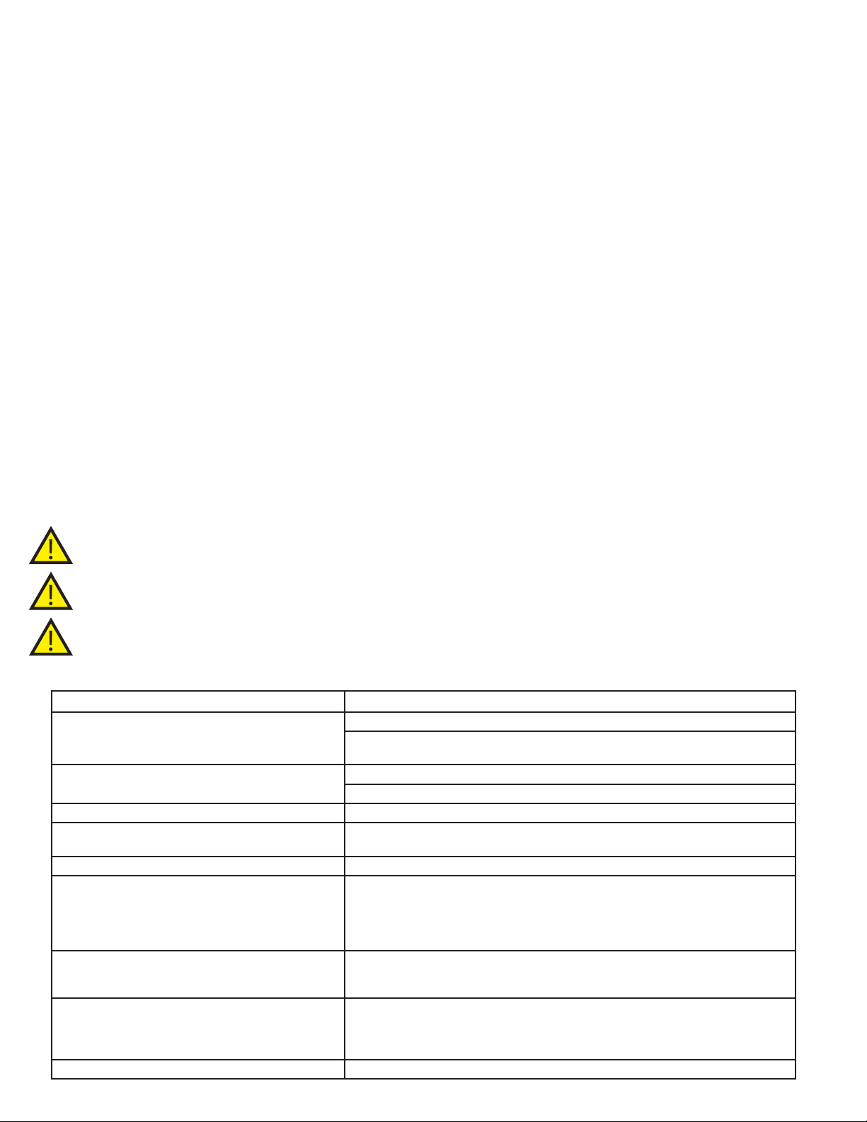
SECTION 7: TROUBLESHOOTING
PROBLEM CORRECTIVE ACTION
Laser has no response, fan is off.
Laser has no response or LED display, but fan is on.
Laser has power but no output.
Measured power output on a power meter is different
from the LED display.
Fiber does not extend or retract from the cartridge.
An “Er” message appears with system alert beep.
Er 01 - System needs service
Er 02 - System needs service
Er 04 - System needs service
Er 06 - System needs service
Audible “beep” on Laser continually sounds when
foot pedal is depressed.
Wireless foot pedal does not activate laser.
I don’t see my issue
Check that the power cord is securely plugged into back of the laser unit. See section 2.1.
Check that the power switch on the back panel is turned to the on (I) position.
Make sure the key is inserted into the switch, and the key is turned on. See section 2.2.5.
Check that the laser stop switch is in the down position. If not, depress the button. See section 2.2.5.
Laser will need to be returned for repair. See Section 6.1
Laser will need to be returned for repair. See Section 6.1
Make sure the power meter is calibrated for use with 810 nm wavelength devices.
If the output remains different See section 4.1.2 and/or section 6.1.
Make sure the 20' of ber cartridge still contains ber. If some ber remains present see section 3.1.5.
First attempt to clear the error message. Turn the laser system off and wait for 5 minutes.
Turn laser back on. If the error clears from the display and the audible “beep” stops, the
unit was able to make operational adjustments and the laser should perform its function. If
the error message and audible “beep” continues, the laser must be sent in for adjustment.
Make note of error code. See section 6.1.
Turn laser off for 5 minutes. Turn laser back on. If the audible “beep” stops, the unit was
able to make operational adjustments and the laser should perform its function. If the beep
continues, the laser must be sent in for adjustment. See section 6.1.
Replace 9 Volt battery. If the pedal still fails to activate the laser with new battery, refer to
section 2.2.3 for Wireless Foot Pedal Installation. Make sure there is no metal tables, chairs or
surfaces between the pedal and the laser. Try repositioning the pedal to a different location
or rotating it slightly on the oor.
Contact Customer Care at (877) 236-4408 or [email protected] for assistance.
15
Page 16
SECTION 8: ELECTROMAGNETIC COMPATIBILITY (EMC)
The Precise® LTM 5 Watt Soft Tissue Diode Laser needs special precautions regarding the EMC and needs to be
installed and put into service according to the EMC information provided in this manual.
Portable and mobile RF communications equipment can affect the Precise LTM. The use of accessories, transducer,
and cables other than those specied by the manufacture, CAO Group may result in increased emissions or
decreased immunity of the Precise LTM. The Precise LTM should not be used adjacent to or stacked with other
equipment and that if adjacent or stacked use is necessary, the Precise LTM should be observed to verify normal
operation in the conguration in which it will be used.
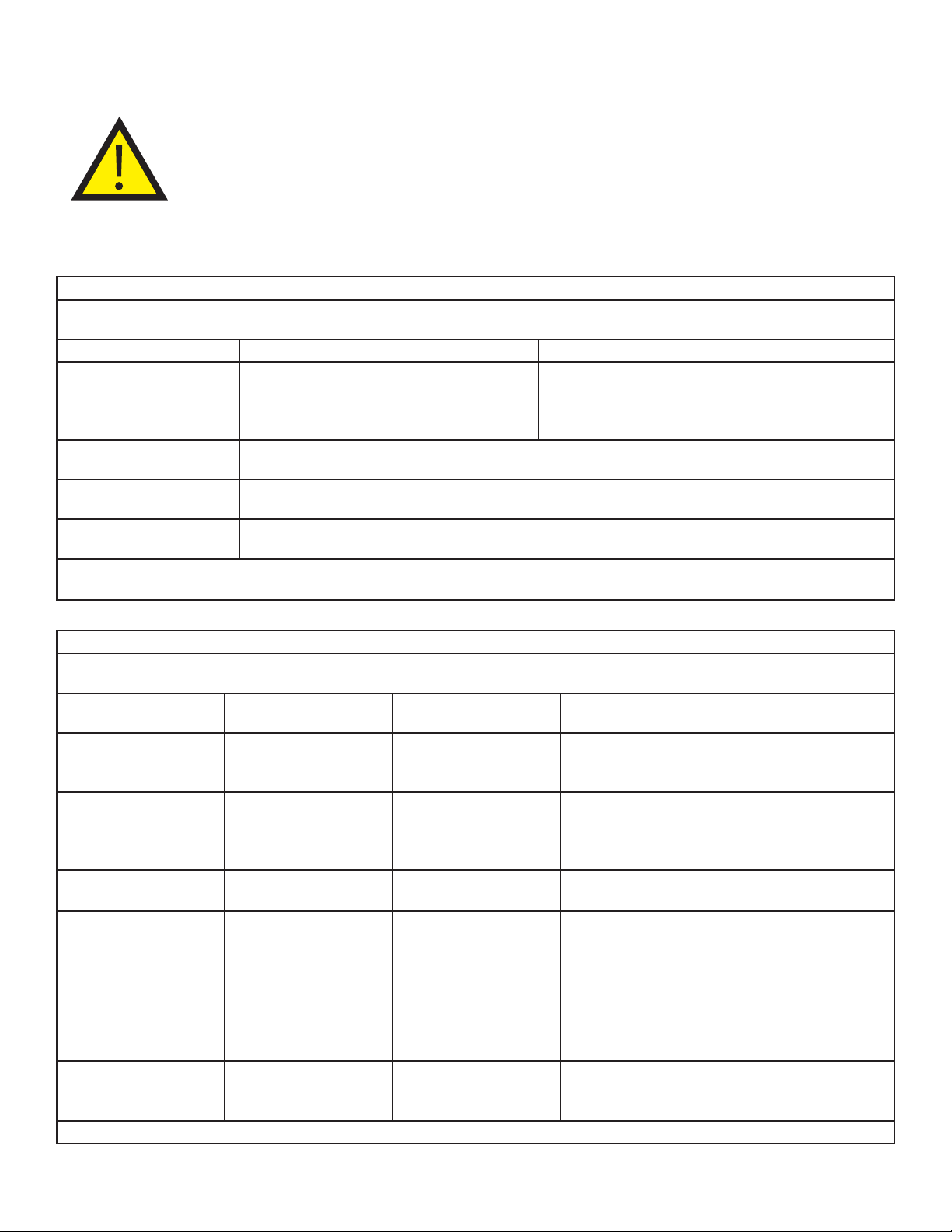
Guidance and manufacturer’s declaration - electromagnetic emissioins
The Precise LTM is intended for use in the electromagnetic environment specied below.
The customer or the user of the Precise LTM laser should assure that it is used in such an environment.
Emissions Test Compliance
RF emissions
CISPR 11
RF emissions
CISPR 11
Harmonic emissions
IEC 61000-3-2
Voltage Fluctuations/
Flicker emissions
The Precise LTM laser is suitable for use in all establishments other than domestic and those directly connected to the public lowvoltage power supply network that supplies buildings used for domestic purposes.
Group 1
Class B
Not available
Not available
The Precise LTM laser uses RF energy only for its internal
function. Therefore, its RF emissions are very low and are
not likely to cause any interference in nearby electronic
equipment.
Guidance and manufacturer’s declaration - electromagnetic emissioins
The Precise LTM is intended for use in the electromagnetic environment specied below.
The customer or the user of the Precise LTM should assure that it is used in such an environment.
Immunity test IEC 60601
test level
Electrostatic
discharge (ESD)
IEC 61000-4-2
Electrical fast
transient/burst
IEC 61000-4-4
Surge
IEC 61000-4-5
Voltage dips,
short interruptions
and voltage
variations
on power supply
input lines IEC
61000-4-11
(50/60 Hz)
magnetic eld
IEC 61000-4-8
NOTE UT is the a.c. mains voltage prior to application of the test level.
± 6 kV contact
± 8 kV air
± 2 kV for power supply
lines
± 1 kV for input/output
lines
± 1 kV differential mode
± 2 kV common mode
<5% UT (>95% dip in UT)
for 0,5 cycle
40% UT (60% dip in UT)
for 5 cycles
70% UT (30% dip in UT)
for 25 cycles
<5% UT (>95% dip in UT)
for 5 sec
3 A/m 3 A/m
Compliance level Electromagnetic environment –
± 6 kV contact
± 8 kV air
± 2 kV for power supply
lines
Not Applicable
± 1 kV differential mode
± 2 kV common mode
<5% UT (>95% dip in UT)
for 0,5 cycle
40% UT (60% dip in UT)
for 5 cycles
70% UT (30% dip in UT)
for 25 cycles
<5% UT (>95% dip in UT)
for 5 sec
guidance
Floors should be wood, concrete or ceramic tile.
If oors are covered with synthetic material, the
relative humidity should be at least 30%.
Main power quality should be that of a typical
commercial or hospital environment.
Main power quality should be that of a typical
commercial or hospital environment.
Main power quality should be that of a typical
commercial or hospital environment. If the user of
the Precise LTM laser requires continued operation
during power mains interruptions, it is recommended
that the Precise LTM laser be powered from an
uninterruptible power supply or a battery.
Power frequency magnetic elds should be at
levels characteristic of a typical location in a typical
commercial or hospital environment.
16
Page 17
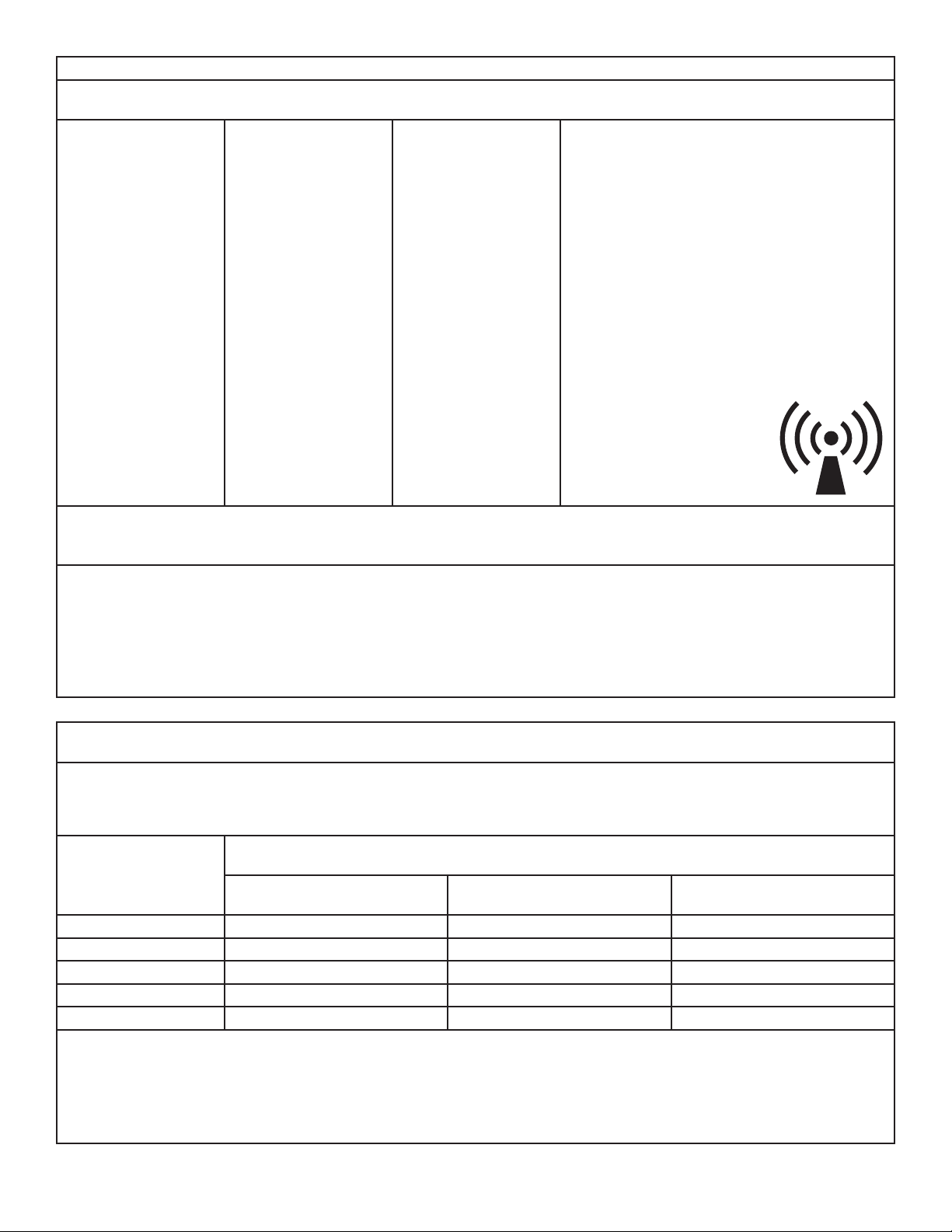
Guidance and Manufacturer’s Declaration - electromagnetic emissions
The Precise® LTM laser is intended for use in the electromagnetic environment specied below.
The customer or the user of the Precise LTM laser should assure that it is used in such an environment.
Conducted RF
IEC 61000-4-6
Radiated RF
IEC 61000-4-3
3 Vrms
150 kHz to 80 MHz
3 V/m
80 MHz to 2,5 GHz
3 Vrms 3 V/m
Portable and mobile RF communications equipment
should be used no closer to any part of the Precise
LTM laser, including cables, than the recommended
separation distance calculated from the equation
applicable to the frequency of the transmitter.
Recommended separation distance
d = [3.5/V1] √ P
d = [3.5/E1] √ P 80 MHz to 800MHz
d = [7/E1] √ P 800 MHz to 2.5 GHz
where P is the maximum output power rating of the
transmitter in watts (W) according to the transmitter
manufacturer and d is the recommended
separation distance in metres (m). Field strengths
from xed RF transmitters, as determined by an
electromagnetic site
surveya, should be less than the
compliance level in each
frequency range. bInterference
may occur in the vicinity of
equipment marked with the
following symbol:
NOTE 1: At 80 MHz and 800 MHz, the higher frequency range applies.
NOTE 2: These guidelines may not apply in all situations. Electromagnetic propagation is affected by absorption and reection
from structures, objects and people.
a
Field strengths from xed transmitters, such as base stations for radio (Bluetooth® cellular/cordless) telephones and land mobile
radios, amateur radio, AM and FM radio broadcast and TV broadcast cannot be predicted theoretically with accuracy. To
assess the electromagnetic environment due to xed RF transmitters, an electromagnetic site survey should be considered. If the
measured eld strength in the location in which the Precise LTM laser is used exceeds the applicable RF compliance level above,
the Precise LTM laser should be observed to verify normal operation. If abnormal performance is observed, additional measures
may be necessary, such as reorienting or relocating the Precise LTM.
b
Over the frequency range 150 kHz to 80 MHz, eld strengths should be less than 3 V/m.
Recommended separation distances between
portable and mobile RF communications equipment and the Precise LTM
The Precise LTM laser is intended for use in an electromagnetic environment in which radiated RF disturbances are
controlled. The customer or the user of the Precise LTM laser can help prevent electromagnetic interference by
maintaining a minimum distance between portable and mobile RF communications equipment (transmitters) and the
Precise LTM laser as recommended below, according to the maximum output power of the communications equipment.
Rated maximum
output power
of transmitter W
150 kHz to 80 MHz
d = [3.5/V1] √ P
Separation distance according to frequency of transmitter
m
80 MHz to 800 MHz
d = [3.5/E1] √ P
800 MHz to 2.5 GHz
d = [7/E1] √ P
0.01 0.12 0.12 0.23
0.1 0.37 0.37 0.74
1 1.17 1.17 2.33
10 3.69 3.69 7.39
100 11.67 11.67 23.33
For transmitters rated at a maximum output power not listed above, the recommended separation distance d in meters (m) can
be estimated using the equation applicable to the frequency of the transmitter, where P is the maximum output power rating of
the transmitter in watts (W) according to the transmitter manufacturer.
NOTE 1: At 80 MHz and 800 MHz, the separation distance for the higher frequency range applies.
NOTE 2: These guidelines may not apply in all situations. Electromagnetic propagation is affected by absorption and reection
from structures, objects and people.
17
Page 18
SECTION 9: LASER SPECIFICATIONS
Precise® LTM Laser Specications
Weight 4.9 lbs
Dimensions
in Inches
(H x W x L)
Laser
Classication
(Per IEC 60825)
Wavelength
Beam
Divergence
Power Range 500 mW to 5 Watts
Pulse Rate
(in Pulse Mode)
Pulse Mode
Duration
Duty Cycle
Aiming Beam
(2 mW)
Audible
Notication
Visual
Notication
Power
Requirements
Amperage
Cordless
Foot Pedal
Operating
Temperature
Operating
& Storage
Humidity
Laser Diode; Class 4 Laser Device
Aiming Beam: 630 nm - 660 nm ± 15 nm
Continuous Mode: 100%
110 - 120 VAC @ 60 Hertz
220 - 240 VAC @ 50 - 60 Hertz
1.5 Amps @ 110 - 115 VAC
0.75 Amps @ 210 - 230 VAC
7.6” x 8.8” x 8.75”
Laser: 810 nm ± 20 nm
9 degres’s ± 1 degree
Fixed: 0.1 Hz
Fixed: 0.05 seconds
Pulse Mode: 50%
Frequency: 2.4 GHz
Battery: 9 Volt Lithium
0 - 30°C / 32 - 86°F
5 - 95% RH
YES
YES
YES
Ordering Information
Accessories
Package of (20) Disposable
Handpiece Tips- Straight
Package of (20) Disposable
Handpiece Tips- Angled
20’ Fiber Cartridge Replacement 002-00206
Protective Glasses - Solid 002-00202
Danger-Laser in Use Signage 002-00034
Handpiece- Autoclavable 002-00178
Fiber Stripper Tool 002-00205
Fiber Cleaver 002-00204
Power Supply & Cord 002-00207
Handpiece Locking Mechanism
(Collet)
Indications for Uses
The Precise® LTM is approved for use by properly trained
and licensed dental professionals (as applicable) for use
in the removal of lesions, excision, incision, vaporization,
ablation, hemostasis, photocoagulation, gingivectomy,
frenectomy, operculectomy, contouring, biopsy, troughing,
ulcer care, abscess care, sulcular debridement, soft tissue
curettage, and removal of inamed edematous tissue on
soft tissue in the oral cavity.
002-00181
002-00182
002-00262
Delivery System Specications
Quartz/Silica
Fiber
Fiber Diameter 400 microns
Retractable
Fiber Delivery
Handpiece Autoclavable - 1
Handpiece Tips Disposable: 20 (per box)
Laser Aperture YES
18
1 Cartridge - approx. 20 ft (6 meters)
Non-Autoclavable - 1
Warranty
Laser 2 Years Parts and Labor
Fiber and Cartridge 6 Months Parts and Labor
Accessories 90 Days Parts and Labor
Page 19

SECTION 10: GLOSSARY OF LASER
TERMINOLOGY
Activate - The action that prepares the laser to emit energy.
Active Medium - The core material of a laser that is responsible for
producing a source of electromagnetic energy when activated
by a power supply. They can be a gas, liquid dye, semi-conductor
chip or a man-made rod of Yttrium, Aluminum Garnet Scandium
or Gallium, or some combination of those elements.
Amplitude - The height of an electromagnetic wave as measured
from the top of one wave to the lowest point on the next wave.
Articulating Arm - A device used to deliver radiant energy
Biopsy - A tissue sample removed from an area of questionable
health. Used for examination and diagnosis of a disease.
Cleave - An act of scoring an optical ber so that it separates
into two pieces.
Coherent - A property of electromagnetic waves in which every
wave is of the same wave length and is in phase with the other
identical waves.
Collagen - The brous protein that is prevalent in bone, tendons,
cartilage, and connective tissue.
Collimated - A characteristic of laser wave lengths where they
travel in a parallel bundle and are slow to deviate.
Continuous Wave - A temporal mode where radiant laser energy
is emitted constantly without interruption. Also known as ( ).
Electromagnetic Components of Energy - Radiation consisting
of electromagnetic waves where the vertical of the wave is the
electrical phase and the lateral component is a magnetic phase.
Laser light is electromagnetic energy.
Electromagnetic Waves - Time varying electric and magnetic
elds propagating through space. They vary in their wave lengths
and frequency.
Electromagnetic Spectrum - A combination of all electromagnetic
radiation arranged by wave length and frequency. Light as we
know it is from the visible portion of the spectrum.
Exposure - Introducing a tissue to laser energy as measured by the
intensity of the power, the frequency, and time.
Frequency - The number of complete oscillations per second of
an electromagnetic wave.
Joule - A unit of energy. Expressed as milliJoules when used in
dental lasers operating in the pulsed mode. 1000 milliJoules per
second equal 1 Watt.
Laser - An acronym for Light Amplication by Stimulated Emission
of Radiation. Lasers are devices that utilize standard electricity
from a wall outlet to stimulate an active medium which will
produce electromagnetic energy that is collimated, coherent,
and monochromatic.
LSO - Laser Safety Ofcer - individual in charge of laser safety,
training, and equipment operation.
Micron - One millionth of a meter. It can also be stated as
-6
10
meter.
Mode - A stable condition of oscillation in a laser. Lasers can
operate is one or more modes.
Molecule - The smallest particle of a substance that retains the
property of that substance. It is composed of one or more atoms.
Nanometer - A billionth of a meter and can also be expressed
as 10 -9. Nanometers and microns are the primary measures of a
wave length used in dental lasers.
Photon - A quantum (unit) of radiant energy. A particle of light.
Power (Output Power) - Expressed as Watts where 1 Joule per
second equals 1 Watt.
Power Density - A measure of exposure of the power in Watts
delivered per square millimeter or square centimeter.
Pulsed - ( ) A temporal emission of laser energy that is distributed
among periods where the laser is actively emitting (on) and periods
of no emission (off). The time period when the laser is not emitting
energy (off) is referred to as period of thermal relaxation and is
designed to allow the tissue to cool between bursts of energy.
Quantum - The smallest unit of measure for radiant (light) energy.
Radiant Energy - The vertical component of electromagnetic
waves as they travel through space. It is measured in Joules or
milliJoules.
Spontaneous Emission - As an electron accumulates incident
energy, it is elevated to a higher energy orbit where it will become
unstable and must emit a photon.
Stimulated Emission - An external source of energy from a power
supply stimulates the unstable electron to return to a more stable
energy level by emitting an additional photon.
Velocity - The rate of speed of an electromagnetic wave as it
travels through space.
Watt - The measure of power is Watts. As used in lasers, 1 Joule per
second is equal to 1 Watt.
SECTION 11: REFERENCES ON LASER
DENTISTRY
1. Leo Meserindino, D.D.S. and Robert Pick, D.D.S. Lasers in
2. Manni , Jeffrey G. Dental Applications of Advanced Lasers.
3. The Institute for Advanced Dental Technologies, Southeld,
4. D.J. Coluzzi, “An Overview of Laser WaveLengths Used
5. Andreas Moritz, et.al. “Treatment of Periodontal Pockets
6. M. Kreisler, et.al., “Effects of Diode Laser Irradiation on the
7. P. Spencer et.al. “Change of Temperature in Subjacent
8. Nora Raffetto and Terri Gutierrez, “Lasers in Periodontal
9. “Safe Use of Lasers in Health Care Facilities”.
BIREX® is a registered trademark of Young Dental Manufacturing, LLC.
CIDEX® is a registered trademark of the Johnson & Johnson
Corporation.
Dentistry. Quintessence Books, 1995 .
Burlington, MA: JGM Associates. Contact at 781-272-6692
MI: “Lasers Dentistry: Clinical Training Seminars”. 1966.
in Dentistry”. Chapter in The Dental Clinics of North
American: Convissar, Robert A. editor, “Lasers and Light
Amplication in Dentistry”, W.B. Saunders Company, 44
(4). October 2000. 753 - 765
with a Diode Laser”. Lasers in Surgery and Medicine, Vol
22. 1998. 302- 311
Survival Rate of Gingival Fibroblast Cell Cultures”, Lasers
Surg Med, Volume 28 (5). 2001. 445 - 450.
Bone During Soft Tissue Laser Ablation”, Journal of
Periodontology, Volume 69 (11). 1998.
Therapy, a Five Year Retrospective”, California Dental
Hygiene Association Journal, Volume 16 (2). Redondo
Beach, CA, 2001. 17-20
American National Standard Institute Standard Z136.3.
19
Page 20
Designed, Engineered and Assembled in the USA by:
CAO Group, Inc.
4628 West Skyhawk Drive
West Jordan, Utah 84084-4501 USA
Customer Service
P + 1.877.236.4408
F + 1.801.256.9287
www.caogroup.com/dental
002-00189 REV.M
 Loading...