

Page 1

Read this manual completely before operating or maintaining this machine.
Failure to follow safety precautions could result in serious injury or death.
Keep this manual for future reference by you and by all those who operate
and maintain this machine.
CHIKUSUI CANYCOM, INC.
90-1 Fukumasu, Yoshii-machi,
Ukiha-shi, Fukuoka, Japan 839-1396
Tel.+81-(0)943-75-2195 Fax.+81-(0)943-75-4396
Off-road Rubber Track Dumper
SC75
Operator's Manual
3570 5101 001
Page 2

http://www.canycom.co.jp/
■
Sales Headquarters TEL +81-(0)943-75-2195 FAX +81-(0)943-75-4396
■
Foreign Trade Center
TEL +81-(0)3-3552-6277 FAX +81-(0)3-3552-6288
All rights reserved. Unauthorized use or reproduction of this material is prohibited.
Authorized Dealer
CHIKUSUI CANYCOM, INC.
Page 3

Notice to Users and Maintenance Personnel
• This machine can be very dangerous if the safety precautions in this manual
and on the labels attached to this machine are not followed. Read and
understand this manual and the safety labels on the machine thoroughly before
using this machine. Always follow the instructions and safety precautions, or
serious injury or death could result.
• This machine should only be used for its intended purpose: hauling and
dumping. Any other use could be dangerous.
• This machine may not be operated on public road or what is considered to
be public road. It is sole responsibility of the operator to consult the local
regulations.
• Do not modify this machine, or do not operate this machine with the safety
covers removed or open. A serious accident could result.
Thank you for purchasing this machine.
This manual provides information needed for safe and effective use of this machine to
those who operate or maintain the machine. Make sure to read and understand the manual
thoroughly before operating the product. Also make sure to read the separate operator's
manual for the engine.
• Store this manual in a safe, accessible place for easy reference.
Page 4

Warning Term Denition
Indicates an imminently hazardous situation which will result
in death or serious injury if the user does not follow the
procedures or the instructions.
Indicates a potentially hazardous situation which could result
in death or serious injury if the user does not follow the
procedures or the instructions.
Indicates a potentially hazardous situation which could result
in minor to moderate injury or damage to the machine if the
user does not follow the procedures or the instructions.
Indicates important information which needs particular
attention.
In this manual, the following four warning terms are used to signal the four levels of hazard
(or seriousness of possible accidents). Read and understand what they mean and always
follow the instructions in this manual.
Warning Terms Used in this Manual
NOTE
Notice to Owner
• Be sure that everyone who uses this machine, including those who rent or
lease this machine, receives a copy of this Operator's Manual and understands
the importance of reading and following the information in this manual.
Page 5

Warranty and After-Sales Service
Chikusui Canycom, Inc. provides you a warranty through Canycom U.S.A. A copy of this
warranty is reproduced in the back of the manual.
Warranty
Consult your local Canycom dealer or our company’s sales department regarding service
orders or any questions or problems that may arise when using this machine. Please
make sure to have the product name, serial number, and the make and type of the engine
handy at the time of contact. The model and serial number can be found on the model
label as shown below, and the make and type of the engine can be found in Chapter5
"Specications" of this manual (Page12).
After-Sales Service
Location of Model Label Model Label
The replacement or repair parts for this product shall remain available for seven years after
the production of this type of machine is discontinued.
Availability of Spare Parts
3570M-0005-020E
3570M-0005-010E
Location of Model Label
Page 6

Contents
1. Safety 1
Safety Labels . . . . . . . . . . . . . . . . . . . . . . . . . . . . . . . . . . . 1
Safety Precautions. . . . . . . . . . . . . . . . . . . . . . . . . . . . . . . 3
Training
. . . . . . . . . . . . . . . . . . . . . . . . . . . . . . . . . . . . . . . . . . . . . . . . . . . . . . .
3
Preparation . . . . . . . . . . . . . . . . . . . . . . . . . . . . . . . . . . . . . . . . . . . . . . . . . . . . 3
Operation. . . . . . . . . . . . . . . . . . . . . . . . . . . . . . . . . . . . . . . . . . . . . . . . . . . . . . 4
Servicing
. . . . . . . . . . . . . . . . . . . . . . . . . . . . . . . . . . . . . . . . . . . . . . . . . . . . . .
8
2. Controls and Components 10
Name and Function of Controls . . . . . . . . . . . . . . . . . . . 10
3. Specications 12
Product Specications . . . . . . . . . . . . . . . . . . . . . . . . . . 12
Contents of the Tool Bag
. . . . . . . . . . . . . . . . . . . . . . . .
13
4. Operation 14
Preparation
. . . . . . . . . . . . . . . . . . . . . . . . . . . . . . . . . . . .
14
Pre-start up Inspection. . . . . . . . . . . . . . . . . . . . . . . . . . . . . . . . . . . . . . . . . . 14
Checking and Filling Fuel . . . . . . . . . . . . . . . . . . . . . . . . . . . . . . . . . . . . . . . 14
Driving. . . . . . . . . . . . . . . . . . . . . . . . . . . . . . . . . . . . . . . . 16
Starting . . . . . . . . . . . . . . . . . . . . . . . . . . . . . . . . . . . . . . . . . . . . . . . . . . . . . . 16
Driving . . . . . . . . . . . . . . . . . . . . . . . . . . . . . . . . . . . . . . . . . . . . . . . . . . . . . . . 19
Stopping . . . . . . . . . . . . . . . . . . . . . . . . . . . . . . . . . . . . . . . . . . . . . . . . . . . . . 22
Parking. . . . . . . . . . . . . . . . . . . . . . . . . . . . . . . . . . . . . . . . . . . . . . . . . . . . . . . 22
Page 7

Working. . . . . . . . . . . . . . . . . . . . . . . . . . . . . . . . . . . . . . . 24
Dumping . . . . . . . . . . . . . . . . . . . . . . . . . . . . . . . . . . . . . . . . . . . . . . . . . . . . . 24
Using Safety Prop. . . . . . . . . . . . . . . . . . . . . . . . . . . . . . . . . . . . . . . . . . . . . . 26
Folding/Unfolding Step . . . . . . . . . . . . . . . . . . . . . . . . . . . . . . . . . . . . . . . . . 27
5. Maintenance 28
Maintenance Schedule . . . . . . . . . . . . . . . . . . . . . . . . . . 28
List of Fluids. . . . . . . . . . . . . . . . . . . . . . . . . . . . . . . . . . . 33
Greasing and Lubricating Points . . . . . . . . . . . . . . . . . . 33
List of Consumables and Spares . . . . . . . . . . . . . . . . . . 34
Removing and Installing Body Panels . . . . . . . . . . . . . . 35
Engine Compartment . . . . . . . . . . . . . . . . . . . . . . . . . . . . . . . . . . . . . . . . . . . 35
Engine . . . . . . . . . . . . . . . . . . . . . . . . . . . . . . . . . . . . . . . . 37
Engine Oil . . . . . . . . . . . . . . . . . . . . . . . . . . . . . . . . . . . . . . . . . . . . . . . . . . . . 37
Oil Filter . . . . . . . . . . . . . . . . . . . . . . . . . . . . . . . . . . . . . . . . . . . . . . . . . . . . . . 39
Air Cleaner. . . . . . . . . . . . . . . . . . . . . . . . . . . . . . . . . . . . . . . . . . . . . . . . . . . . 39
Spark Plugs . . . . . . . . . . . . . . . . . . . . . . . . . . . . . . . . . . . . . . . . . . . . . . . . . . . 40
Drive Train. . . . . . . . . . . . . . . . . . . . . . . . . . . . . . . . . . . . . 41
Tracks . . . . . . . . . . . . . . . . . . . . . . . . . . . . . . . . . . . . . . . . . . . . . . . . . . . . . . . 41
HST (HydroStatic Transmission) Fluid . . . . . . . . . . . . . . . . . . . . . . . . . . . . . 42
Line Filter and Suction Filter . . . . . . . . . . . . . . . . . . . . . . . . . . . . . . . . . . . . . 43
Transmission Oil. . . . . . . . . . . . . . . . . . . . . . . . . . . . . . . . . . . . . . . . . . . . . . . 44
Drive Belts . . . . . . . . . . . . . . . . . . . . . . . . . . . . . . . . . . . . . . . . . . . . . . . . . . . . 46
Belt Stoppers. . . . . . . . . . . . . . . . . . . . . . . . . . . . . . . . . . . . . . . . . . . . . . . . . . 47
Parking Brake . . . . . . . . . . . . . . . . . . . . . . . . . . . . . . . . . . . . . . . . . . . . . . . . . 47
Control Stick . . . . . . . . . . . . . . . . . . . . . . . . . . . . . . . . . . . . . . . . . . . . . . . . . . 49
Greasing and Lubricating . . . . . . . . . . . . . . . . . . . . . . . . . . . . . . . . . . . . . . . 51
Page 8

Hydraulic System . . . . . . . . . . . . . . . . . . . . . . . . . . . . . . . 52
Hydraulics Belt . . . . . . . . . . . . . . . . . . . . . . . . . . . . . . . . . . . . . . . . . . . . . . . . 52
Electrical System . . . . . . . . . . . . . . . . . . . . . . . . . . . . . . . 53
Battery . . . . . . . . . . . . . . . . . . . . . . . . . . . . . . . . . . . . . . . . . . . . . . . . . . . . . . . 53
Fuses
. . . . . . . . . . . . . . . . . . . . . . . . . . . . . . . . . . . . . . . . . . . . . . . . . . . . . . . .
55
After Use Care . . . . . . . . . . . . . . . . . . . . . . . . . . . . . . . . . 56
After Normal Use
. . . . . . . . . . . . . . . . . . . . . . . . . . . . . . . . . . . . . . . . . . . . . .
56
After Cold Weather Use . . . . . . . . . . . . . . . . . . . . . . . . . . . . . . . . . . . . . . . . . 56
Storage . . . . . . . . . . . . . . . . . . . . . . . . . . . . . . . . . . . . . . . 57
6. Troubleshooting 58
Troubleshooting . . . . . . . . . . . . . . . . . . . . . . . . . . . . . . . . 58
7. Transporting 62
Hauling
. . . . . . . . . . . . . . . . . . . . . . . . . . . . . . . . . . . . . . .
62
Loading and Unloading . . . . . . . . . . . . . . . . . . . . . . . . . . . . . . . . . . . . . . . . . 63
Hoisting. . . . . . . . . . . . . . . . . . . . . . . . . . . . . . . . . . . . . . . 64
Page 9

Warranty
Warranty Certicate is attached at the end of this manual.
* Have the warranty certicate signed and sealed after you have received and fully
understood the instructions for handling this machine and received the receipt.
Appendix
• Operator's Manual for the Engine
* Be sure to read and understand it together with this manual .
Page 10

Safety 1
-1-
Safety Labels
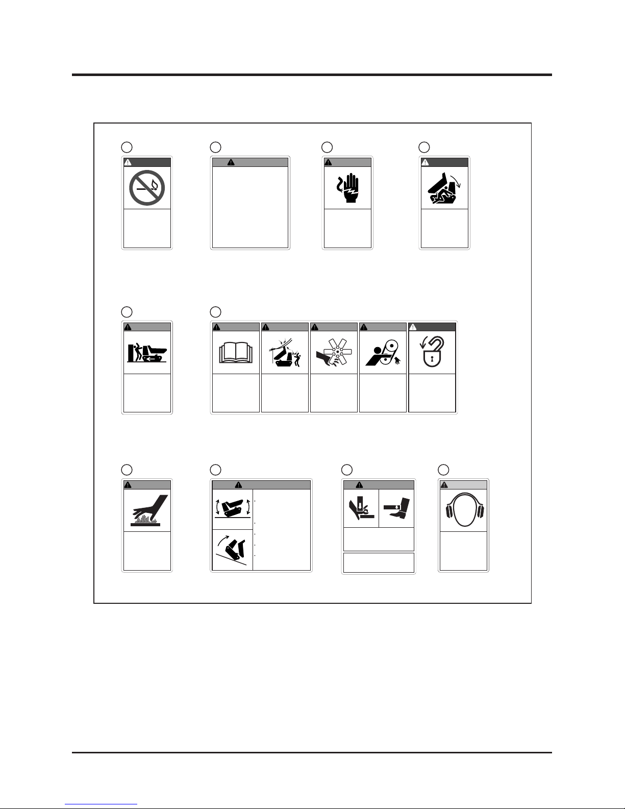
The safety labels shown on the next page are attached to the machine. See the illustration
below for the location and the illustration on the next page for the content of each label on
the machine.
• Loca te all the warning labels attached to this machine. Read and follow the
instructions and precautions in them. Failure to do so could result in serious injury
or death to the operator or bystanders.
• Keep the labels clean and legible. Do not use solvents or gasoline to clean the
labels.
• Replace these labels immediately if they have been removed, have fallen off or
become illegible. Use the part number, on the label or shown in this manual, to
order a replacement label from your CANYCOM representative.
3570M-0101-011E
4
6
7
3 (On the hood)
(On the hood)2
9
8
10
1 5
Page 11
Safety
-2-
1
Cr us h haz ar d.
Beware of obstacles
when reversing or
tu rn in g.
Alw ays
operate slowly and
keep two meter or
more clearance
.
3570 5037 001
WARNING!
Fla mmable liqu id
p re s en t . Ke e p
awa y a ll ig nit io n
sourc es
.
3677 5042 001
DANGER!
Do n ot r evers e th e p ol ar it y.
Re
ver se po lari ty m ay cause
fir e or ex plosi on. M ake sure
t h e j u m p e r c a b l e s a r e
connected correctly
.
Av oi d s ho r t- ci rc ui t.
S hor tc ir cu it m ay ca us e f ir e or
explosion.
Do no t tou ch t he ele ctr ica l
ter mina ls or wi res. S hock or
el ec troc utio n co uld o cc ur i f
accidental contact is made.
3570 5028 002
WARNING!
Hazardous voltage.
Use of unappro
ved
t es t p ro b es o r
conductive objects
i s s t r i c t l y
pr oh ib it ed. Se e
operation manual.
3677 5047 001
WARNING!
Cru sh ha zard. To
pr e
ven t d ea th o r
ser iou s i njury,
do
N OT pl a c e a n y
par t of
your body
under the loadi ng
deck.
3677 5046 001
DANGER!
E le c t ri c s h oc k
hazard. Keep away
from electric power
li ne s a nd ut il ity
poles
.
WARNING!
Rea d and FUL LY
u nd er st an d
t he
opera tor's m anual
b e f or e us e o r
maint enanc e
.
WARNING!
Po we r so urc es .
H yd r au l i c a n d
e le c t ri c p o
w er
sourc es are present . Loc kou t AL L
en er gy so ur ces
before ser vicin g.
DANGER!
Mov ing belt s ca n
entangle hand and
ar m. K eep h and s
a wa y
to av o id
injur y.
WARNING!
Moving fan blades
ca n se
ve r ha nd
and fingers.
Keep
h an d s a wa y
t o
avoid i njury.
WARNING!
3570 5036 001
Hot sur face s. Do
NOT tou ch.
3677 5043 001
WARNING!
Upset hazard.
Accelerate or decelera te slo wly. Sudd en
starts, stops, or turns
can cause tip-over.
Never ope
rate on slope
in excess
of 25 degrees.
Avoid running over
obstacles.
Hold onto guide rail at
all times
.
Ke ep fee t o n f oo t
plat form (step) at all
times
.
3570 5038 000
WARNING !
3570 5021 001
Cr us h ha za rd . H ol d th e
step firm ly when
rais ing or
lo wer in g.
D ro pp in g s tep
could caus e ser ious injur y.
WARNING!
STEP LOCK KNOB
Pull th e knob to rais e
or lower the st ep.
N oi s e H az ar d .
We ar a pp ro ve d
e ar p r ot e c ti o n
durin g operatio n.
3570 5039 000
CAUTION!
3570M-0101-021E
3677 5042 0011
3570 5028 002
2
3570 5037 0015
3570 5036 001
6
3677 5047 0013
3677 5043 0017
3570 5038 000
8 3570 5039 000103570 5021 0019
3677 5046 0014
Page 12

Safety 1
-3-
This section contains safety precautions to follow when operating and maintaining the
machine. Read and understand the precautions in this section as well as throughout this
manual and follow them when operating or maintaining the machine. Failure to follow safety
precautions could result in property damage, serious injury or death to the operator or
bystanders.
Safety Precautions
All operators and mechanics should receive practical instructions from their employer or
renter. Such instructions should cover the following issues:
• It is essential to familiarize yourself with the controls, safety labels and the proper
use of the machine.
• Never allow people unfamiliar with these instructions to operate or service the
machine. Local regulations may restrict the minimum age of the operator.
• The operator is responsible for the accidents or hazards caused to other people or
their property.
• Do not carry passengers other than the operator.
• Always keep in mind that care and concentration is required when working with
ride-on machines.
• Loss of control on a slope cannot be regained by the application of the brake. The
main reasons for loss of control are:
→ insufcient grip of tracks.
→ excessive speed.
→ misjudging of the ground conditions, especially slopes.
→ incorrect distribution of load.
Training
Preparation
• Always wear protective footwear, long trousers, hardhat, safety glasses and ear
protection when operating or servicing the machine. Proper clothing will minimize
the chance of injury. Do not operate the equipment if you have long hair, loose
clothing, or jewelry; all of which may get tangled in moving parts. Do not operate
the machine barefoot or with open sandals.
Page 13

Safety
-4-
1
Operation
• Fuel is highly ammable. See Checking and Filling Fuel, page 14, for important
safety information on handling fuel.
• Never handle fuel or grease, service the engine, or recharge the battery in the
presence of re or spark.
• Perform the daily pre-startup inspection (see Preparation, pages 14-15) before
starting the machine. Repair or replace damaged parts before starting the machine.
• Do not operate the engine in a conned space where dangerous carbon monoxide
fumes can accumulate.
• Do not touch the engine, mufer or exhaust pipe while the engine is running or
soon after it has stopped. These areas will be very hot and can cause burns.
• Do not operate the machine under the inuence of alcohol or drugs.
• Always check for obstacles before operating on new terrain.
• Before starting the engine and moving the machine, be sure all persons are a safe
distance away from the machine. Sound the horn to warn bystanders.
• Always hold the guide rail with one hand to keep your posture when the machine is
moving.
• On a slippery surface, travel slowly and exercise caution to reduce the chance of
skidding or sliding out of control. Never operate on ice.
The stability of the machine is affected by the speed, rate of steering, terrain and the load.
Always pay close attention to these factors or a loss of control or tip over could occur,
resulting in property damage, serious injury or death.
General Driving
Page 14

Safety 1
-5-
• Always make certain that there is no obstacle or a person behind the machine when
backing up. After conrming that it is safe to back up, move slowly and avoid sharp
turns.
• To reduce the risk of tip over,pay special attention when encountering an obstacle
or a slope, or when braking on a slope or during a turn. See Driving on a Slope on
the next page.
• Never attempt to drive over a large obstacle such as rock or fallen tree.
• Always travel slowly and use extra caution when operating on unfamiliar terrain. Be
alert when traveling on changing terrain.
• Never operate on terrain that you are not comfortable with. Avoid terrain that is so
rough, slippery or loose that you feel like you could tip over.
• Do not operate the machine near the edge of a cliff, an overhang or a slide area.
• Do not m ake sudden maneuvers. A sudden start, stop, or turn can make the
machine lose control and could cause a tip over. Be especially cautious when
traveling on soft or wet ground.
• Drive at a safe speed, taking into account the surface gradient, surface conditions
and load.
• Use an observer to help direct the machine when the visibility is poor, terrain is
rugged or hilly, or maneuvering room is limited. The observer should be able to see
the machine and its immediate surroundings, and should give pre-arranged signals
to direct the operator.
Page 15

Safety
-6-
1
Driving on a Slope
• Always follow proper procedures for driving on a slope as described in this manual.
• Driving on a slope in a wrong manner can cause a loss of control or a vehicle tip
over. Check the terrain carefully before attempting to drive on a slope.
• Never drive on a slope that you are not comfortable with. Avoid a slope that is so
rough, slippery, or loose that you feel like you could tip over.
• When driving up a slope, proceed at a steady rate of speed and throttle position.
• Never move the throttle lever or the control stick suddenly.
• Dri v e strai g h t up o r down a s lope. Av o id tur n i ng on a slope. I f turn i n g is
unavoidable, make only a short, gradual and steady turn.
• If the engine stalls or loses traction during a climb and cannot make it to the top
of the slope, do not try to turn the machine around. Carefully back down slowly,
straight down the slope.
• When going over the top of a slope, go slow; an obstacle, a sharp drop, or another
vehicle or person could be on the other side of the crest.
• Avoid driving the machine across a slope. If it is unavoidable, drive across a slope
slowly and carefully.
• Without a load, drive the machine backwards up a slope (operator's step uphill)
when climbing, and drive it forward when going down a slope.
• Driving on a slope can be dangerous. It can result in a tip over and cause
serious injury or death. Take the following precautions.
Page 16

Safety 1
-7-
• With a load, drive the machine forward up a slope (operator's step downhill) when
climbing, and drive it backwards when going down a slope. Be especially cautious
when operating on a slope with a load.
• When driving down a slope, use the control stick so that the machine travels down
at the minimum speed. Use the engine speed to help keep the machine speed low.
Loading and Driving with a Load
• The maximum payload for this machine is 1650lbs. (750 kg). Do not exceed this
maximum payload under any circumstance.
• Do not operate on a slope steeper than 20 degrees when carrying a load. Do not
carry more than 660lb (350 kg) when operating on a slope between 15 and 20
degrees. Keep in mind that liquid concrete will shift in the bucket and hence its
center of gravity also shifts, affecting the stability of the machine.
• Load cargo in the bucket so the weight is evenly distributed. Keep in mind that
liquid concrete will shift in the bucket and hence its center of gravity also shifts.
When carrying a solid cargo, strap the cargo to the load deck to prevent the cargo
from shifting. Ensure that cargo does not obstruct the operator's eld of view.
• When carrying a load, drive at a reduced speed. Allow a greater distance for
braking.
• Before crossing a bridge or an overpass, make certain that the total combined
weight of the machine, the load and the driver is within the stated weight limit for
the bridge or the overpass. Then, proceed carefully and at a constant speed.
Dumping
When dumping material from the bucket, take the following precautions.
• Always follow the proper procedures for dumping as described in this manual.
• Only operate the bucket with the engine running.
• Perform the dump operation on a at, level and stable surface whenever possible.
Raising or lowering the load deck on a slope or rough terrain could result in a tip
over.
Page 17

Safety
-8-
1
Parking
• Park the machine on a at, level and stable surface. If parking on a slope is
unavoidable, apply the parking brake and block the tracks at the lower end of the
machine.
→ Without a load, park the machine with the operator's step toward the uphill
→ With a load, park the machine with the operator's step toward the downhill
→ Do not park sideways on a slope.
• Observe all the previous precautions for driving, driving on a slope, loading and
driving with a load, and dumping.
• Whenever you park the machine, apply the parking brake and stop the engine.
Rem o ve t h e k e y w h ene v er y o u l e ave the mac h ine u nat t end e d t o pre v ent
unauthorized use or accidental starting.
• Gasoline is extremely ammable and can be explosive. When parking the machine
indoors, make certain that the building is well ventilated and that the machine is not
close to any source of ame or spark, including appliances with pilot lights.
Servicing
• Do not service the machine when the engine is running.
• Make certain that there is adequate ventilation when operating the engine indoors
to prevent poisoning by exhaust gas.
• Make sure all hydraulic line connectors are tight and all hydraulic hoses and lines
are in good condition before applying hydraulic pressure to the system.
• Make certain that all persons are at a safe distance away from the machine when
raising or lowering the bucket.
• Do not move the machine or leave it unattended with the bucket in the raised
position.
• Engage the bucket safety prop if you must place any part of your body under the
bucket in the raised position.
Page 18

Safety 1
-9-
• Keep your body and hands away from pinhole leaks or nozzles that eject hydraulic
uid under high pressure. Use paper or cardboard, not your hands, to search
for leaks. Hydraulic uid escaping under pressure can have sufcient force to
penetrate the skin and cause serious injury.
• Check all fuel lines on a regular basis for tightness and wear. Tighten or repair them
as needed.
• If the engine must be running to perform a service, keep hands, feet, clothing and
any part of the body away from any moving part, especially the cooling fan and the
belts at the side of the engine.
• Do not touch the engine, mufer, or exhaust pipe while the engine is running or
soon after it has stopped. These areas will be very hot and can cause burns.
• The engine must be shut off before checking or adding oil.
Page 19
Controls and Components
-10-
2
Name and Function of Controls
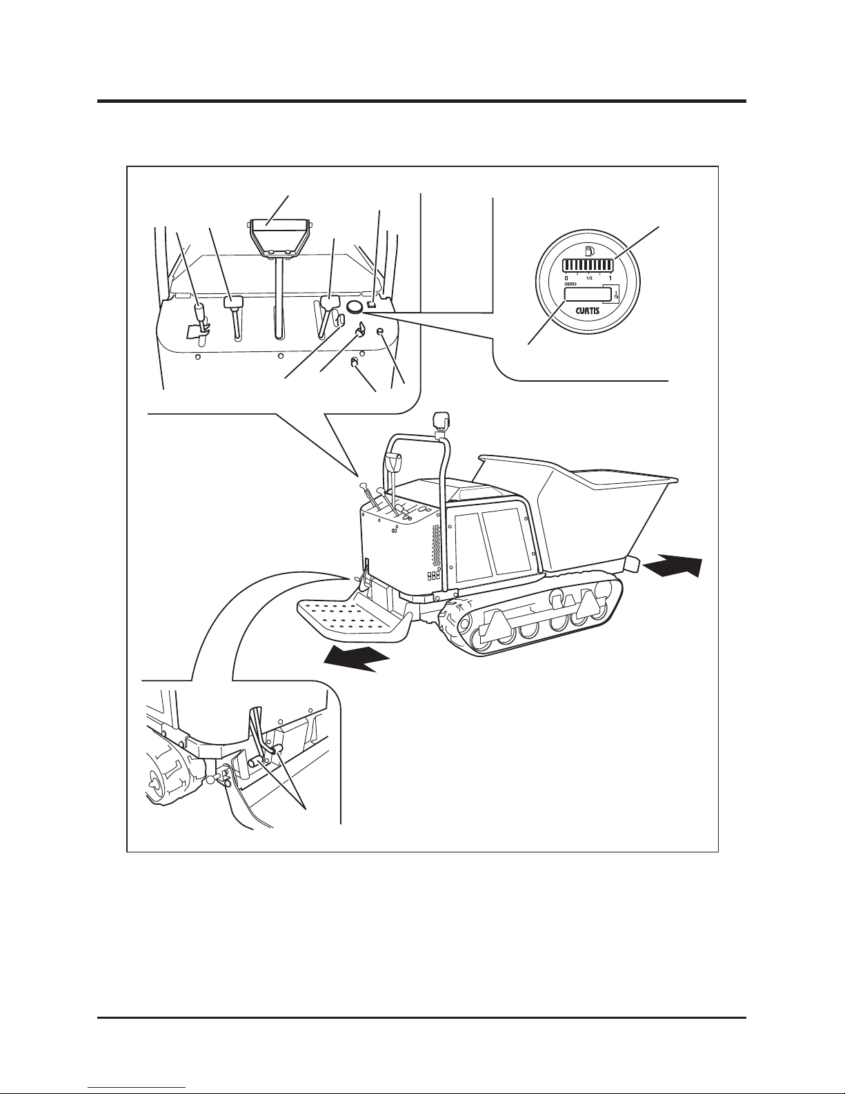
1 Dump Lever . . . . . . . . . . . . Raises or lowers the bucket.
2 Dump Pedals . . . . . . . . . . . Coupled to the dump lever and raises or lowers the
bucket.
3570M-0201-010E
Forward
Backward
1
3
4
5
7
6
8
9
10
12
2
11
Page 20

-11-
Controls and Components 2
3 Clutch Lever . . . . . . . . . . . . Disengages the clutch to help start the engine in the cold.
4 Control Stick. . . . . . . . . . . . Control stick is used to control the traveling direction
(forward or backward, as well as left or right) and speed of
the machine.
5 Parking Brake Lever
. . . . .
Parking brake lever is used to park the machine securely.
6 Throttle Lever . . . . . . . . . . . Throttle lever is used to control the engine speed.
7 Engine Oil Warning Lamp . Lig hts u p w he n the M ai n S wi t ch i s t ur ne d t o the
[ (run)] position. If there is no problem, it goes off when
the engine is started. If a problem is detected when the
engine is running, it lights up.
8 Main Switch . . . . . . . . . . . . Main switch is used to start or stop the engine.
9 Choke Knob . . . . . . . . . . . . Pulling the choke knob closes the choke valve to help start
the engine in the cold weather. Push the knob back to
open the valve once the engine starts.
10 Horn Button . . . . . . . . . . . . Pressing this button sounds the horn. Use this for warning
during traveling or signaling during operation.
11 Fuel Gauge . . . . . . . . . . . . . Displays the amount of fuel in the tank.
12 Hour Meter . . . . . . . . . . . . . Hour meter displays and records the total amount of time
the machine has been in use, in the unit of 0.1 hour.
Page 21

Specications
-12-
3
· Use this product properly after understanding its specications thoroughly.
Product Specications
Model and Type
SC75
One-Way Dump
Machine Mass kg(lbs) 640(1412.8)
Maximum Payload kN(lbs) 7.35(1653.5)
Dimensions
Overall Length mm(in.) 2695(106.1)
Overall Width mm(in.) 900(35.4)
Overall Height mm(in.) 1470(57.9)
Track Contact Length mm(in.) 965(38.0)
Track Gauge mm(in.) 700(27.6)
Ground Clearance mm(in.) 115(4.5)
Loading Deck Height mm(in.) 450(17.7)
Loading Deck
I n n e r
Dimensions
Length mm(in.) 1295(51.0)
Width mm(in.) 765(30.1)
Height mm(in.) 540(21.3)
Volume Struck
m3(cu. ft.) 0.41(14.5)
Engine
Model Robin EH65DS
Type Air-cooled 4-cycle V-twin Gasoline
Cylinder (Bore×Stroke) mm(in.) 80X65(3.15×2.56)
Displacement cm3(cu. In.) 653(39.8)
Maximum Output kw(PS)/rpm 16.1(22)/3,600
Maximum Torque N•m(lbf•ft)/rpm 45.6(33.6)/2,500
Starter System Electric
Fuel Automotive Unleaded Gasoline
Fuel Consumption
g/kW•h(oz/PS•h)
310(8.11)
Fuel Tank Capacity L(US gal.) 20(5.3)
Oil Capacity L(US qt.) 1.4(1.48)[1.55(1.64); including oil lter]
Ignition Electronic Ignition
Spark Plugg NGK BP6ES
Electrical
Battery Type 40B19R
Battery Capacity V/AH 12/28
Working Lamp V/W 12/18.4
Page 22
-13-
Specications 3
Model and Type
SC75
One-Way Dump
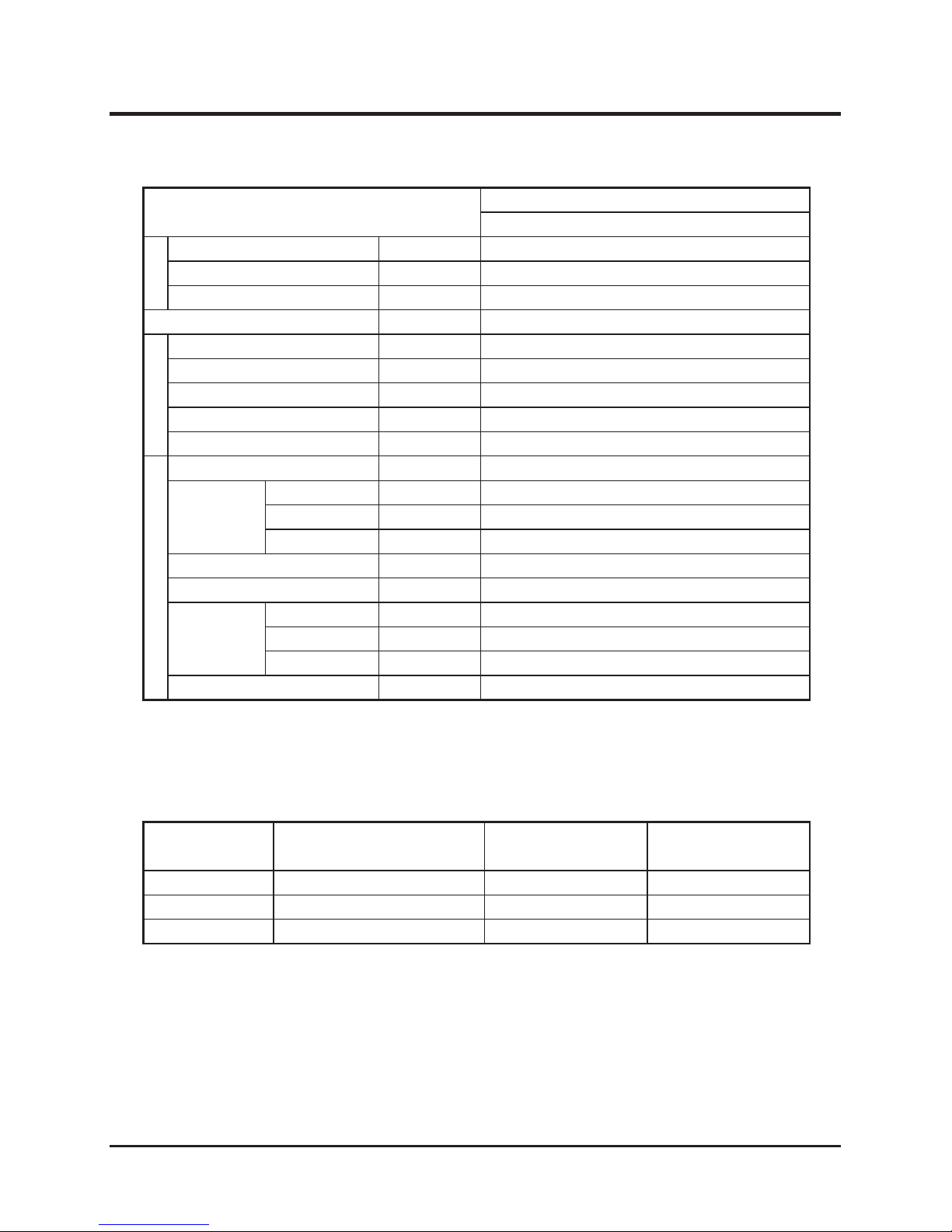
Speed km/h(mph) 0-8.0(0-5.0)
Minimum Turning Radius m(ft) 1.5(4.9)
Gradability Degrees 25(Empty)
HST Oil Capacity L(US qt.) 23(24.3)
Drive Train
Main Transmission Twin HST
Steering Twin HST, 1 Lever
Brakes Internally Expanding
Track Size 200×42×72
Tranamission Oil Capacity L(US qt.) 2.0(2.11)
Dumping System
Dumping System Front Dump
Hydraulic
Pump
Type Gear Pump
Max. Speed
rpm 2,300
Max. Discharge
L/min(US Gal./min)
17.6(4.65)
Relief Pressure MPa(psi) 9.8(1421)
Cylinder(Bore X Stroke) mm(in.) 60X400(2.36X15.75)
Performance
Max. Angle Degrees 90
Lifting Time Sec 4.0
Lowering Time
Sec 3.4
Hydraulic Fluid Capacity L Shared with HST System
*These specications are subject to change without notice.
P e r f or -
m a n c e
No. C o n t e n t Q u a n t i t i y N o t e
1 Operator's Manual 1 This Manual
2
Operator's Manual for the Engine
1
3 Engine Service Tool 1
for Servicing the Engine
Contents of the Tool Bag
Page 23
Operation
-14-
4
• Keep re and spark away when handling fuel.
• Always stop the engine before refueling.
• Do not ll beyond the limit (bottom of the ller lter) so that fuel will not
overow. In case fuel is spilt, wipe out immediately.
Start up Inspection
Preparation
Always perform an inspection before use.
Refer to the Maintenance Schedule (page 28) for the inspection schedule and procedure.
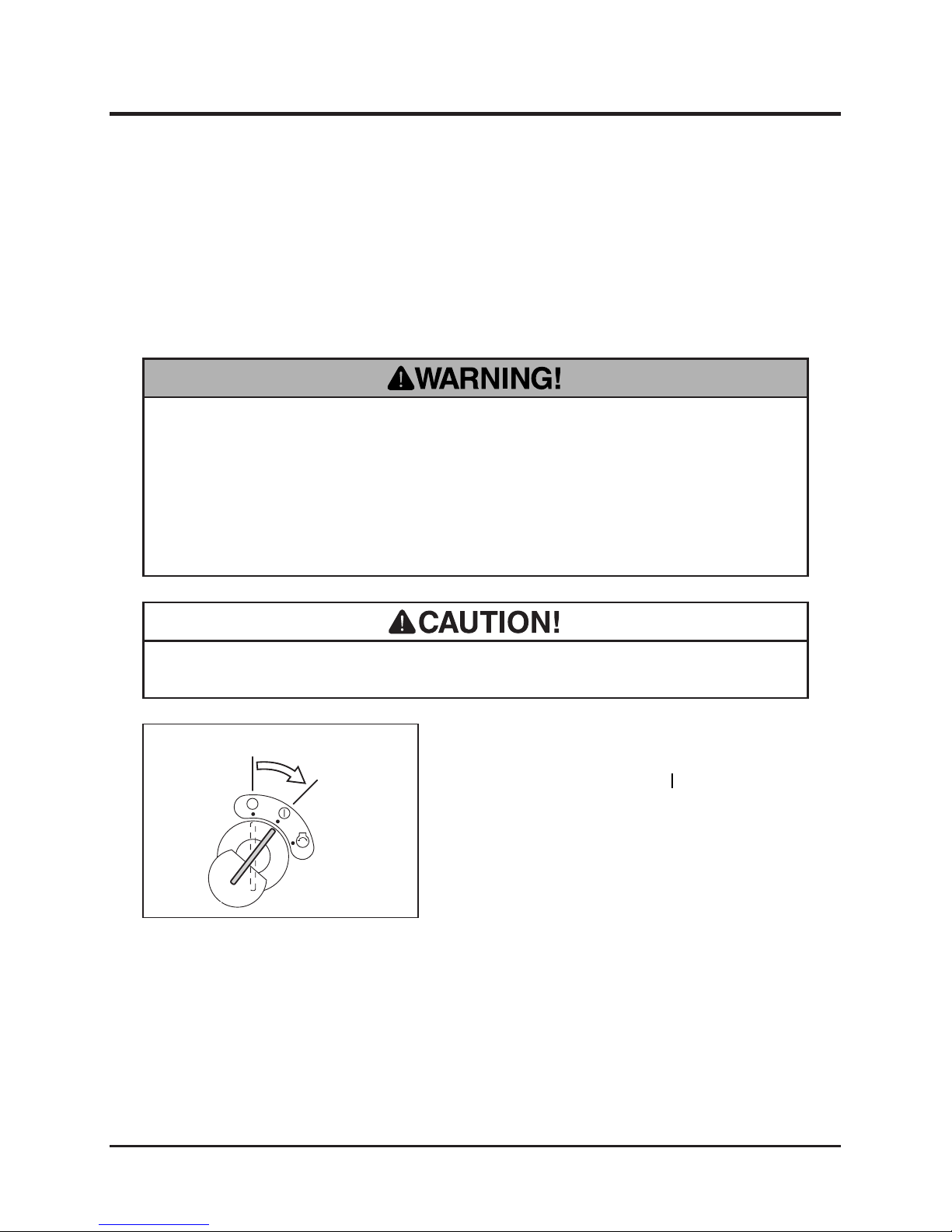
Checking and Filling Fuel
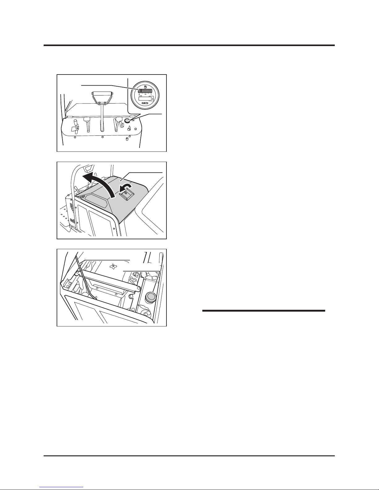
1. Insert the key into the main switch.
2. Turn the main switch to [ (run)] position.
3570M-0401-010E
Stop
Run
• Pinch point; watch your hands when shutting the engine hood.
Checking Fuel
Page 24
-15-
Operation 4
• Fuel : Automotive Unleaded Gasoline
• Fuel Tank Capacity : 20L(5.3US gal.)
NOTE
3570M-0401-020E
Fuel Gauge
3. Check the fuel gauge.
3570M-0401-030E
Engine Hood
1. Open the engine hood.
Filling Fuel
3570M-0401-040E
Engine Hood Stay
Fuel Filler Cap
2. Hold the engine hood open with the engine
hood stay. Open the fuel ller cap and ll
fuel. Put the fuel ller cap back in place and
tighten it securely. Undo the engine hood
stay and close the engine hood.
Page 25
Operation
-16-
4
Driving
• Always start and run the engine in a well ventilated place.
• Always make certain of the safety of your surroundings when starting the
engine.
• Do not turn the starter when the engine is running. The starter motor and/or the
engine may be damaged.
• Do not turn the starter for more than 15 seconds. If the engine does not start,
wait for 30 seconds or more before attempting to start again.
• In the winter or cold climate, warm up the engine thoroughly before driving the
machine. Driving with the cold engine may cause excessive wear.
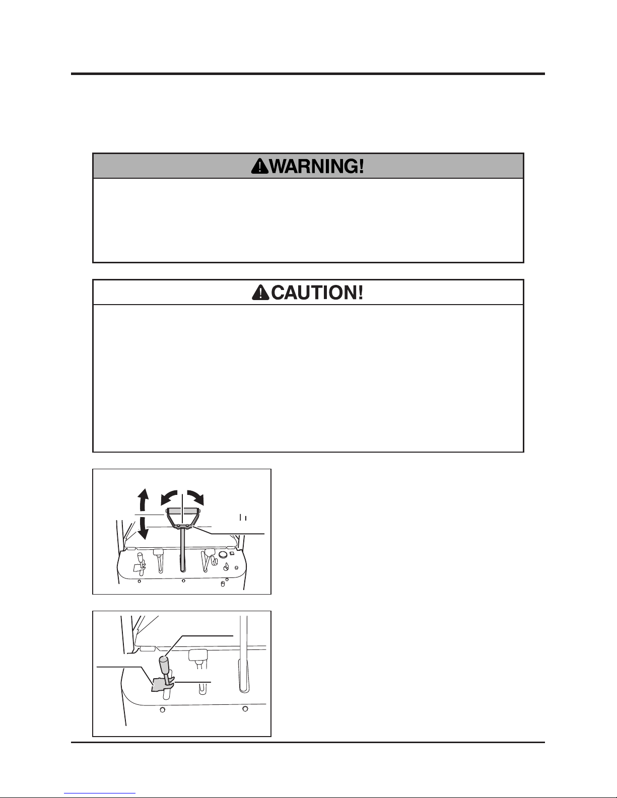
1. Make sure the control stick is in the neutral
position and on center (not twisted).
Starting
2. Make sure the dump lever is in the neutral
position and the lock plate is in the locked
position.
3570M-0402-010E
Control Stick
Neutral
Center
3570M-0402-020E
Dump Lever
Lock Plate
Neutral
Page 26
-17-
Operation 4
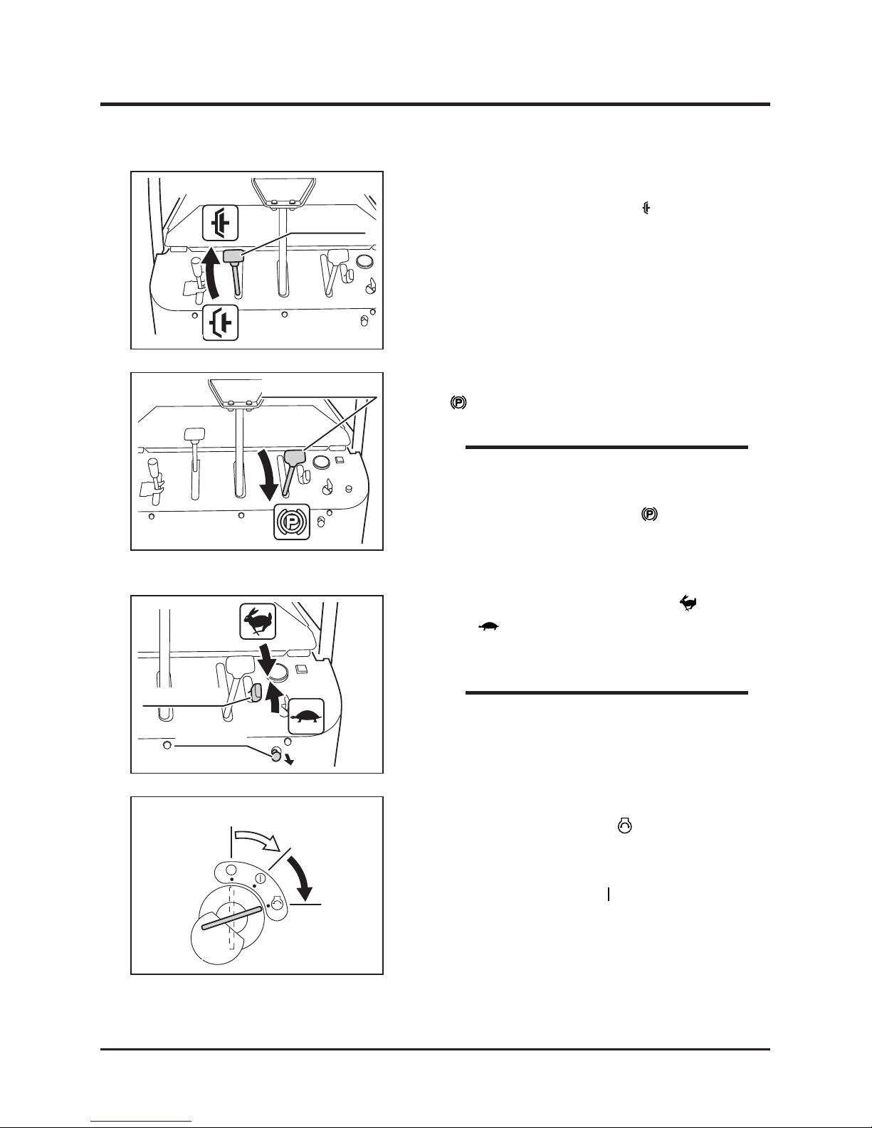
3. Move t he clutch l ever to [ (engaged)]
position.
5. Set the throttle lever in between [ (fast)]
and [ (slow)] positions.
6. Pull the choke knob.
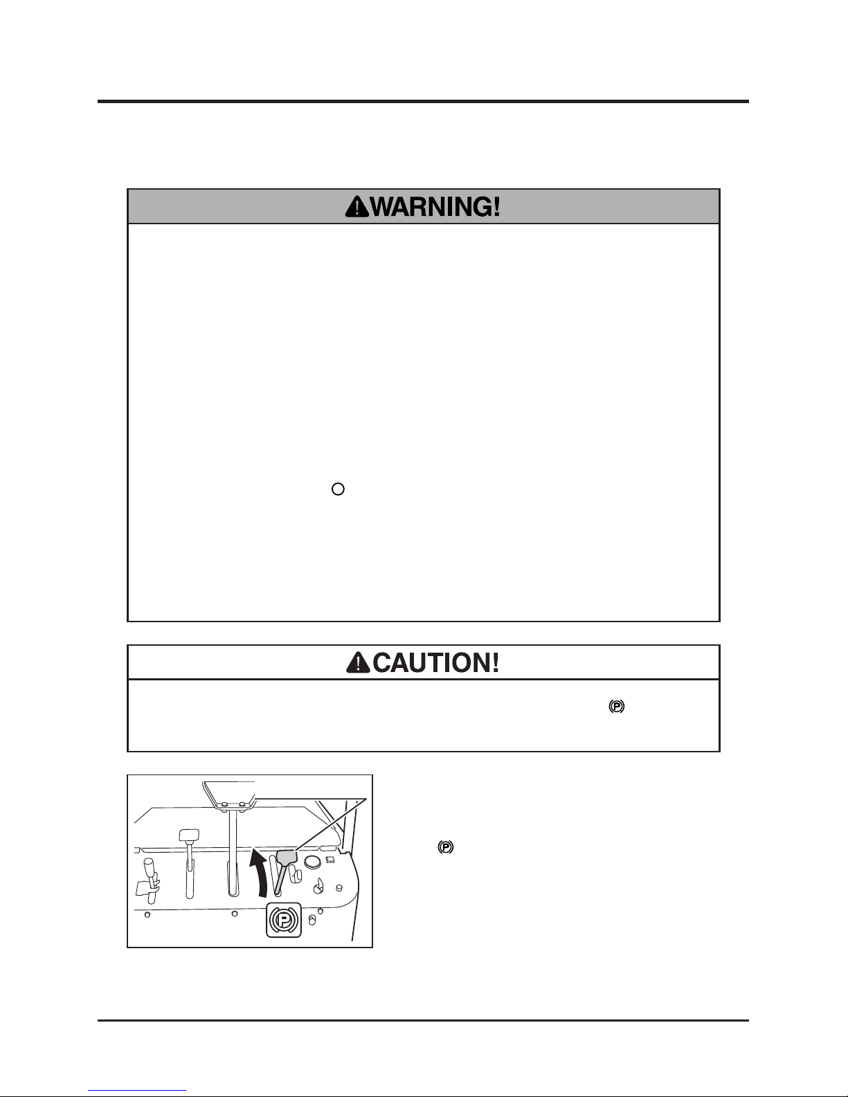
4. M o v e t h e p a r k i n g br a k e l e v er t o
[ (engaged)] position.
• The engine cannot be started unless the
control stick is in neutr al and centered,
and the parking brake is in [ (engaged)]
position. This is due to the safety feature on
this product.
7. Insert the key into the main switch.
8. Turn the main switch to [ (start)] position
to start the engine. Once the engine starts,
release the key immediately; the switch will
automatically return to [ (run)] position.
Normal Starting
3570M-0402-030E
Clutch Lever
3570M-0402-040E
Parking Brake Lever
3570M-0402-050E
Throttle Lever
Choke Knob
3570M-0402-060E
Stop
Start
Run
NOTE
• W h e n t h e e n g i n e i s w a r m , i t i s n o t
necessary to pull the choke knob.
NOTE
Page 27
Operation
-18-
4
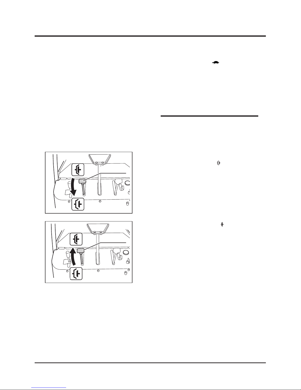
9. Move the throttle lever to [ (slow)] position.
10. Push the choke knob to the original position.
11. Allow the engine to warm up by running
it for 3-5 minutes without any load. (It is
not necessary when the engine is already
warm.)
3. Move the clutch lever to [ (disengaged)]
position.
4.Fo ll o w 4 t o 1 0 in th e n orm al st art in g
procedure above.
Starting in Cold Weather
3570M-0402-070E
Clutch Lever
3570M-0402-030E
Clutch Lever
• Drive the machine gently in the rst week or
so, (40-50 hours) of use after purchase for
breaking-in.
NOTE
5.Move the clutch lever to [ (engaged)]
position.
6. Allow the engine to warm up by running it for
3-5 minutes without any load.
Page 28
-19-
Operation 4
1. M a k e ce r t a i n o f t h e s a f e t y o f y o u r
surroundings.
2. Move the parking brake lever away from
[ (engaged)] position.
• Do not allow bystanders to come near the machine when driving.
• Always make certain of the safety of your surroundings before driving; start
slow.
• Always make certain of the safety of your surroundings before turning
• Do not make sudden start, acceralation, change of speed, change of direction,
or stop. Do not turn at speed. Avoid sudden maneuvers; this may cause the
operator to fall or the machine to tip over.
• Do not turn the key to [ (off)] position while traveling. Machine can lose
stability and tip over.
• Always move the control stick back to the neutral and centered position before
releasing. Letting it go from other operationg positions may result in sudden
deceleration and can cause the machine to tip or the operator to fall.
Driving
3570M-0402-080E
Parking Brake Lever
• Do not operate the control stick when the parking brake is in [ (engaged)]
position. It can wear out the brake.
Page 29
Operation
-20-
4
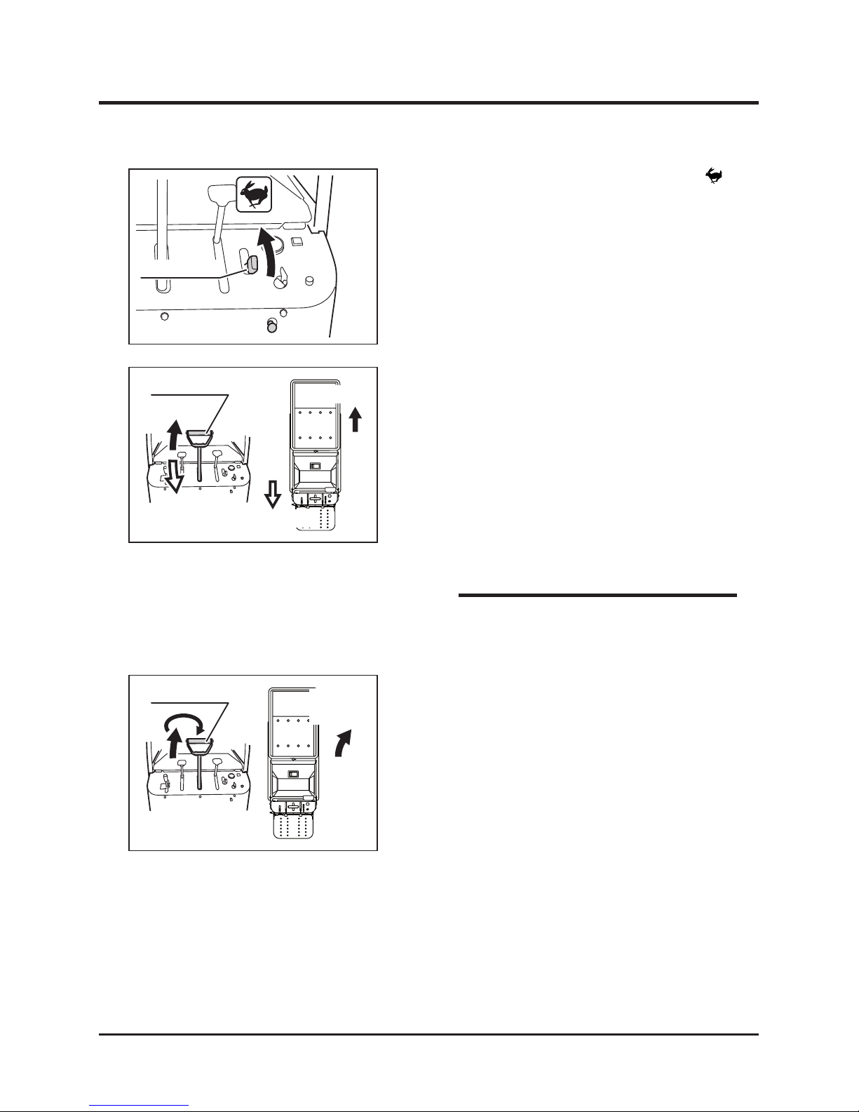
4. Move the control stick forward gradually to
move the machine forward. The angle of the
control stick controls the machine speed.
5. Move the control stick backward gradually to
move the machine backward. The angle of
the control stick controls the machine speed.
6. Move the control stick gradually forward and
twist it right (clockwise) to turn right.
3570M-0402-110E
Control Stick
Right Turn
Forward
• See Specications (page 13) for the speed
range.
3570M-0402-100E
Control Stick
Forward
Backward
Moving Forward
Moving Backward
NOTE
Turning while Traveling Forward
3. Mo v e t h e t h r ot t l e l e ve r to w a rd [
(fast)] position to increase the engine speed.
3570M-0402-090E
Throttle Lever
Page 30
-21-
Operation 4
3570M-0402-120E
Control Stick
Left Turn
Forward
Turning while Traveling Backward
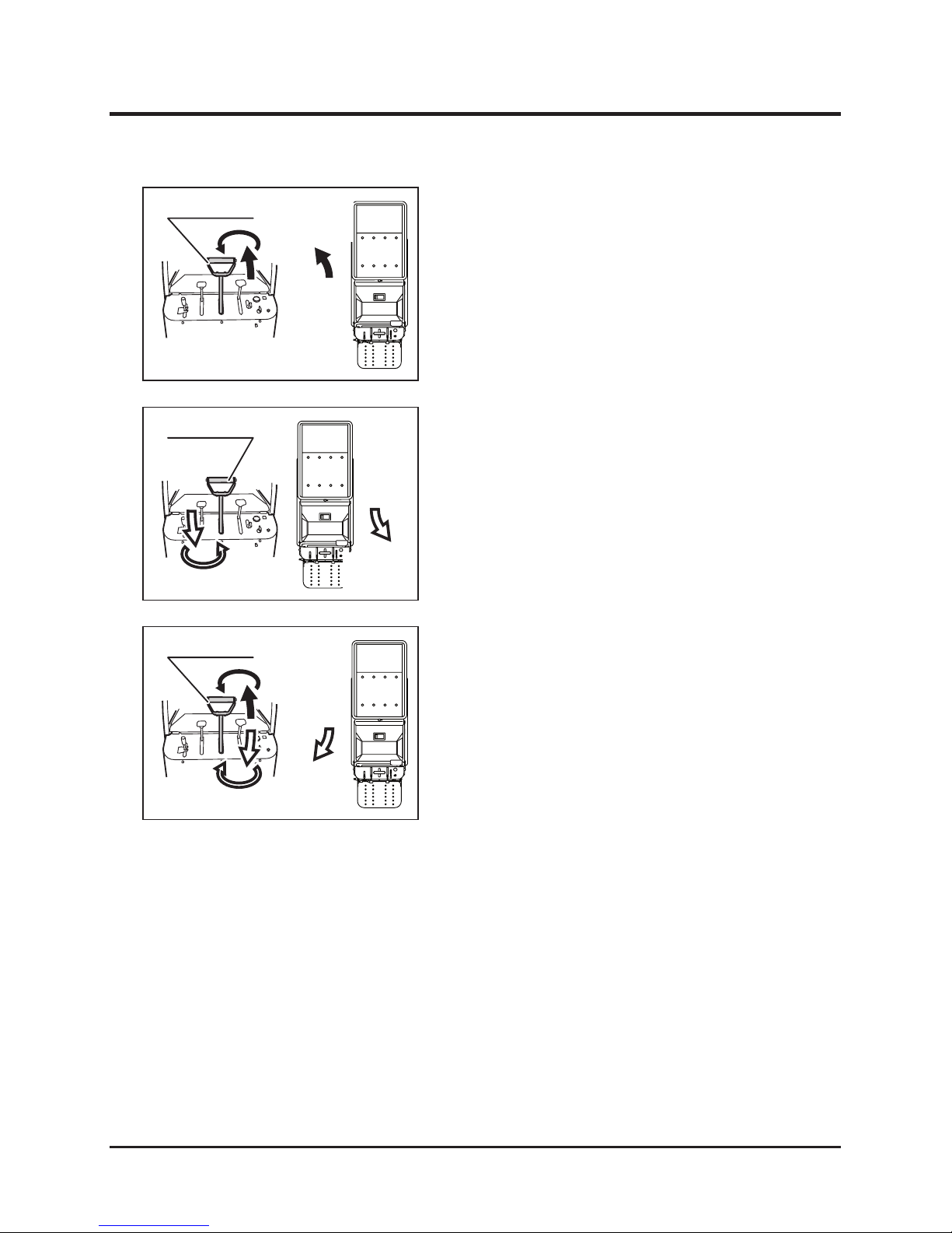
7. Move the control stick gradually forward and
twist it left (counter-clockwise) to turn left.
8. Move the control stick gradually backward
and twist it left (counter-clockwise) to turn
right.
3570M-0402-130E
Control Stick
Right Turn
Backward
3570M-0402-140E
Control Stick
Left Turn
Backward
9. Move the control stick gradually backward
and twist it right (clockwise) to turn left.
Page 31
Operation
-22-
4
1. Stop the machine.
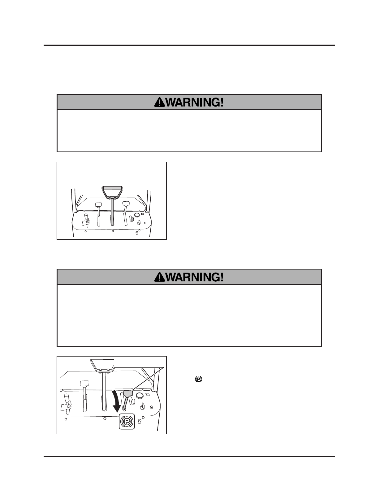
2. M o v e t h e p a r k i n g br a k e l e v er t o
[ (engaged)] position.
• Always park on a rm, level place. Never park on a potentially dangerous place.
• Do not park on a slope. If it is absolutely necessary to park the machine on
a slope, make certain to apply parking brake rmly and block the tracks with
chocks.
Parking
3570M-0402-040E
Parking Brake Lever
• Do not make a sudden stop. The machine may skid or tip over.
• Always park on a rm, level place. Never park on a potentially dangerous place.
Stopping
1. Move t he control stick gradu ally to the
neutral and centered (not twisted) position.
Page 32
-23-
Operation 4
3570M-040-160E
Throttle Lever
3570M-0402-170E
Stop
Start
Run
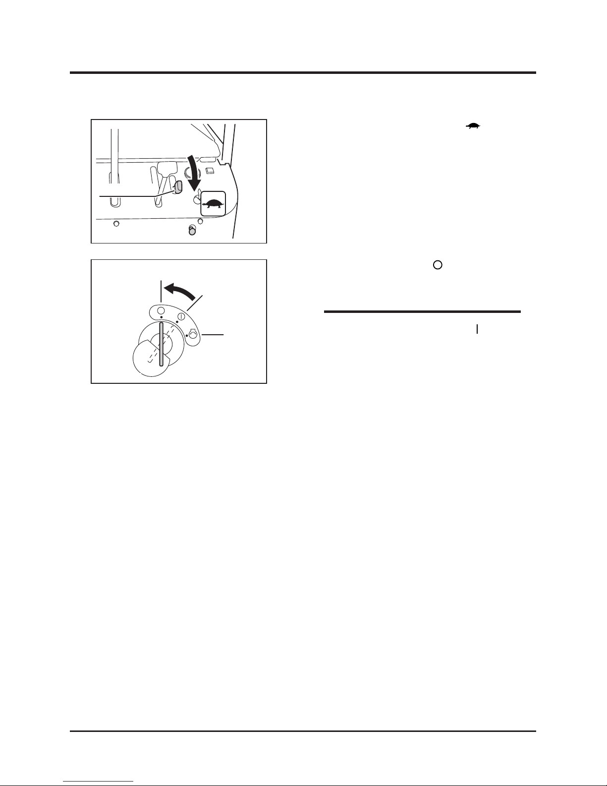
3. Move the throttle lever toward [ (slow)]
position to decrease the engine speed.
4. Turn the main switch to [ (off)] position.
Remove the key from the main switch.
• L e a v in g th e m a i n sw it ch i n [ ( on ) ]
position drains the battery and cause it to
discharge.
NOTE
Page 33
Operation
-24-
4
Working
• Always make certain of the safety of your surroundings when dumping.
• Avoid dumping on a slope. If it is absolutely necessary to dump on a slope,
arrange it so that the machine remains level, or the machine may tip over.
• Always run the engine when dumping.
• When lowering the loaded bucket, slow the engine speed and lower the bucket
gently.
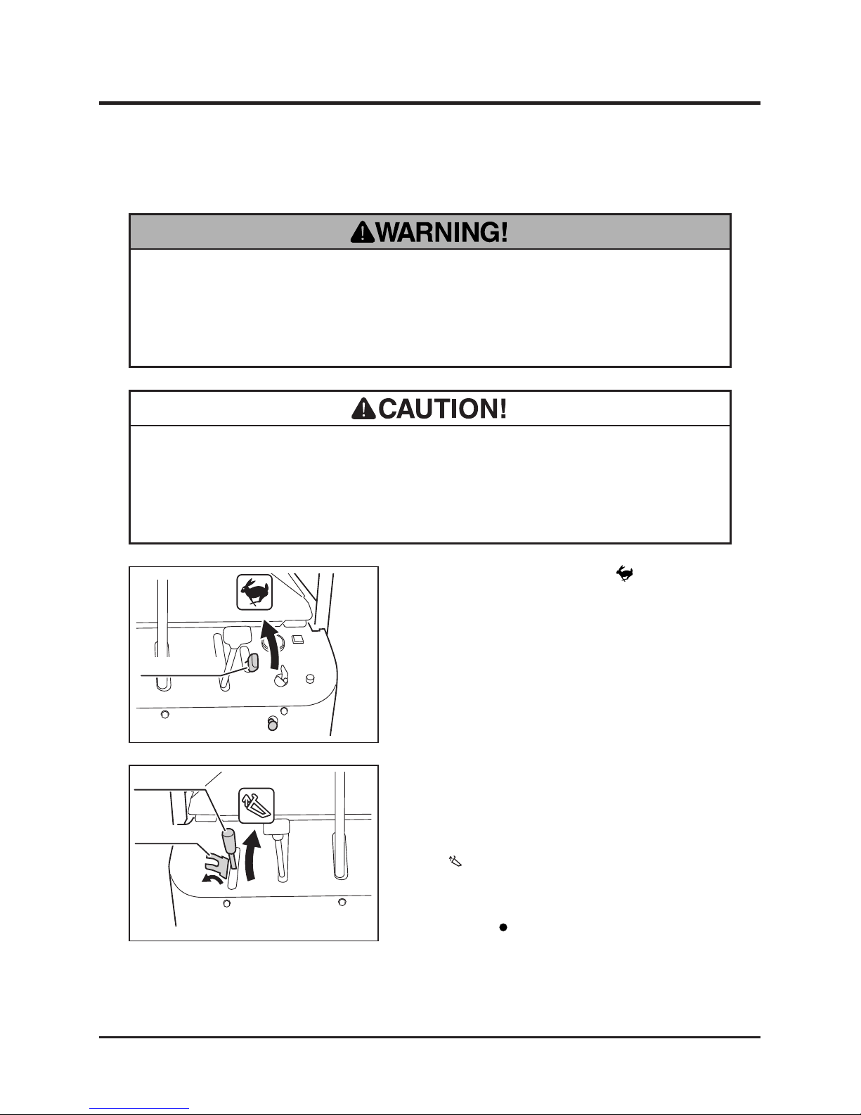
1. Move the throttle lever to [ (fast)] position
to increase the engine speed.
Dumping
2. Turn the lock plate to the side so that the
dump lever can be moved.
3. Move the dump lever graduall y to ward
[ (up)] to raise the bucket.
4. When the bucket reaches its upper limit, a
hissing noise is heard; move the dump lever
back to [ (neutral)] position.
Raising the Bucket with Dump Lever
3570M-0403-020E
Dump Lever
Lock Plate
3570M-0403-010E
Throttle Lever
Page 34
-25-
Operation 4
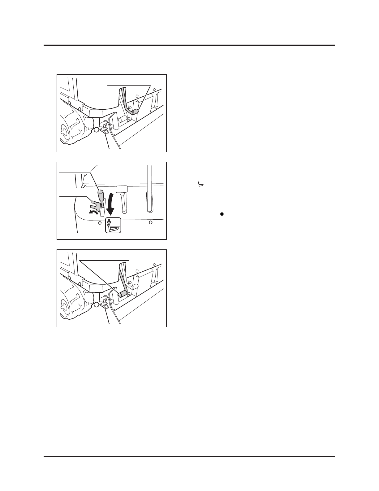
2. Turn the lock plate on the dump lever to the
side so that the dump lever can be moved.
Dump pedal is linked to the dump lever.
3. Step lightly on the dump pedal (up) to raise
the bucket.
4. When the bucket reaches its upper limit, a
hissing noise is heard; release the pedal.
Lowering the Bucket with Dump Lever
3570M-0403-030E
Dump Pedal (Up)
3570M-0403-040E
Dump Lever
Lock Plate
3570M-0403-050E
Dump Pedal (Down)
Raising the Bucket with Dump Pedal
5. Move the dump lever graduall y to ward
[ (down)] to lower the bucket.
6. When the bucket reaches its lower limit, a
hissing noise is heard; move the dump lever
back to [ (neutral)] position.
7. Turn the lock plate back in place to lock the
dump lever.
5. Step lightly on the dump pedal (down) to
lower the bucket.
6. When the bucket reaches its lower limit, a
hissing noise is heard; release the pedal.
7. Turn the lock plate back in place to lock the
dump lever.
Lowering the Bucket with Dump Pedal
Page 35
Operation
-26-
4
Using Safety Prop
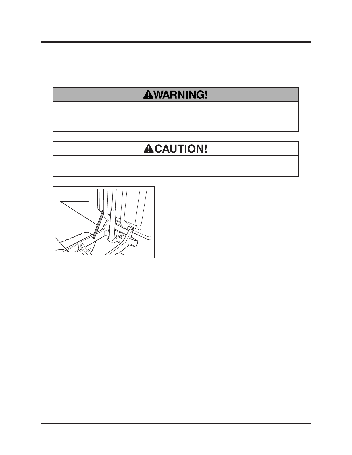
• Place the safety prop under the bucket when inspecting or working under the
bucket.
• Make certain to undo the safety prob before lowering the bucket.
1. Raise the bucket.
2. Hold the bucket with the safety prop.
3570M-0403-060E
Safety Prop
Page 36
-27-
Operation 4
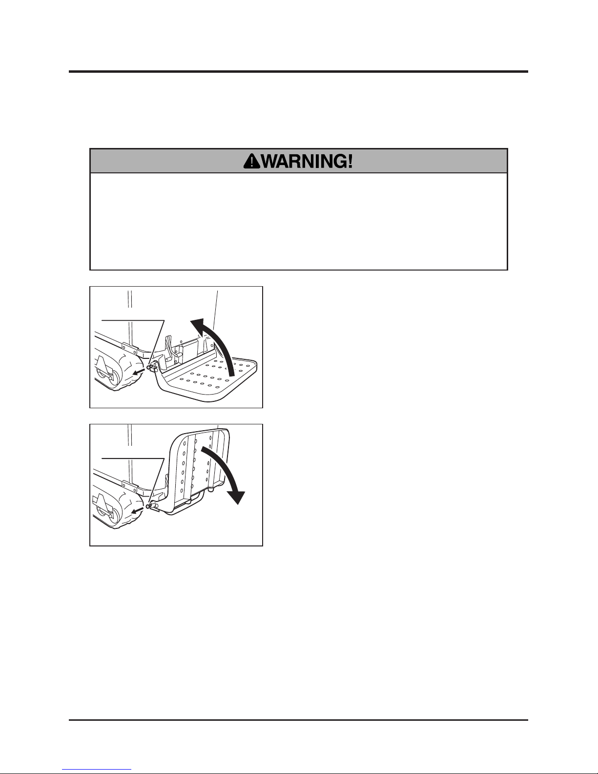
Folding/Unfolding Step
• Hold the step rmly when folding or unfolding the step. Make certain that hands
or ngers are not in the way to be caught by the step when folding or unfolding.
• Make certain that the step is securely locked with the step lock in either
position.
1. Pull the step lock knob.
2. Fold the step. Once the step is fully folded,
release the step lock knob so that the step
locks in this position.
3570M-0403-070E
Step Lock Knob
1. Hold the step rmly and pull the step lock
knob.
2. Unfo ld t he s tep. On ce t he s tep is full y
unfolded, release the step lock knob so that
the step locks in this position.
3570M-0403-080E
Step Lock Knob
Folding the Step
Unfolding the Step
Page 37
Maintenance
-28-
5
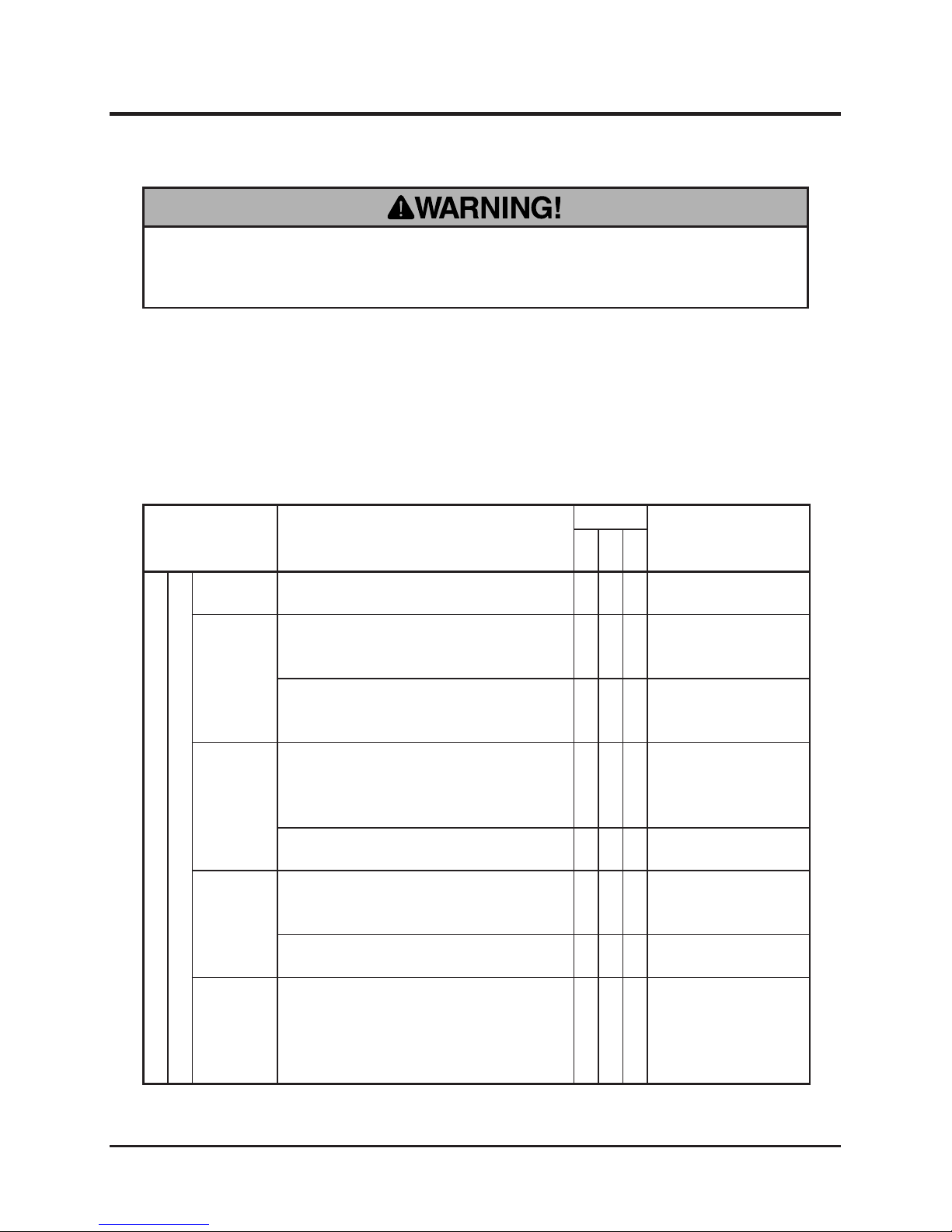
• Follow the scheduled maintenance as described below. Failure to do so may
result in mechanical or property damage, injury or death.
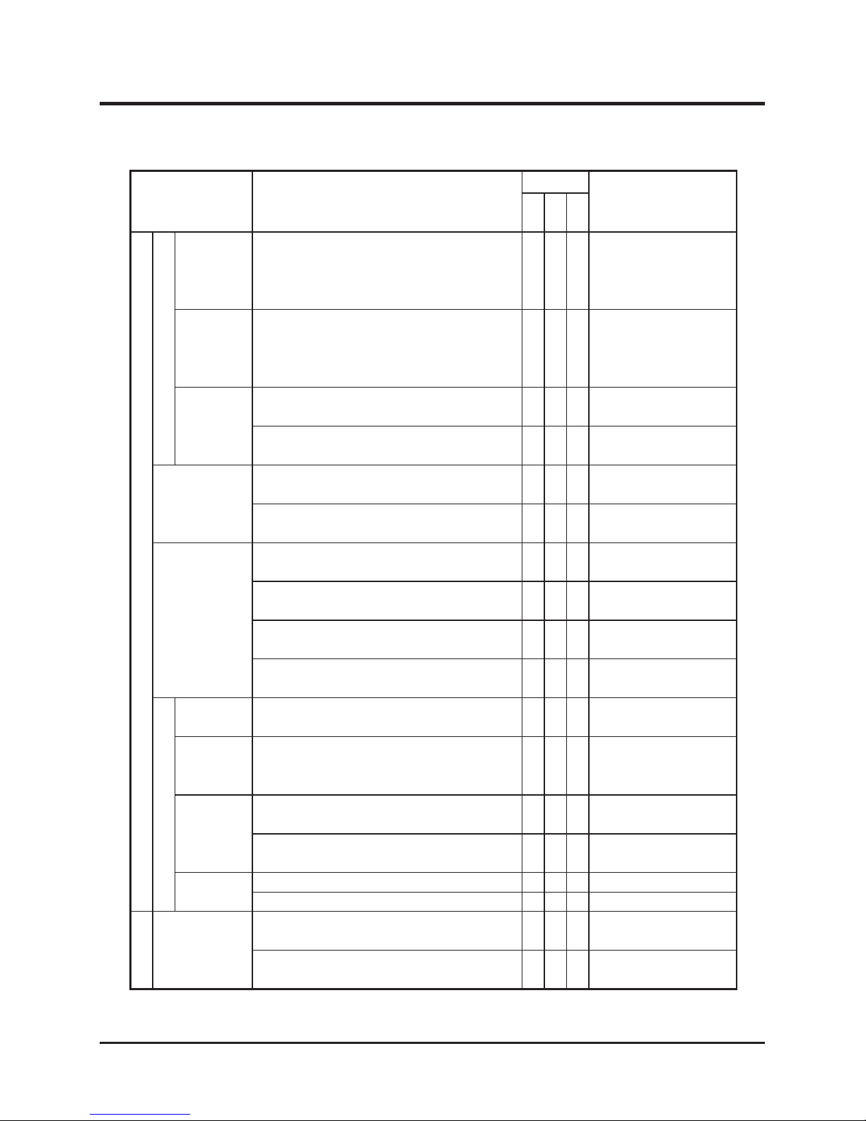
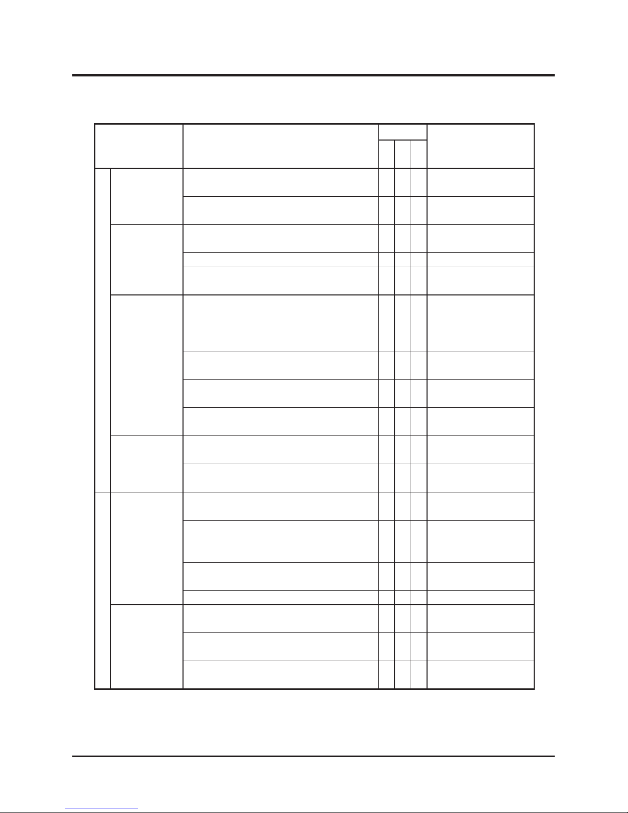
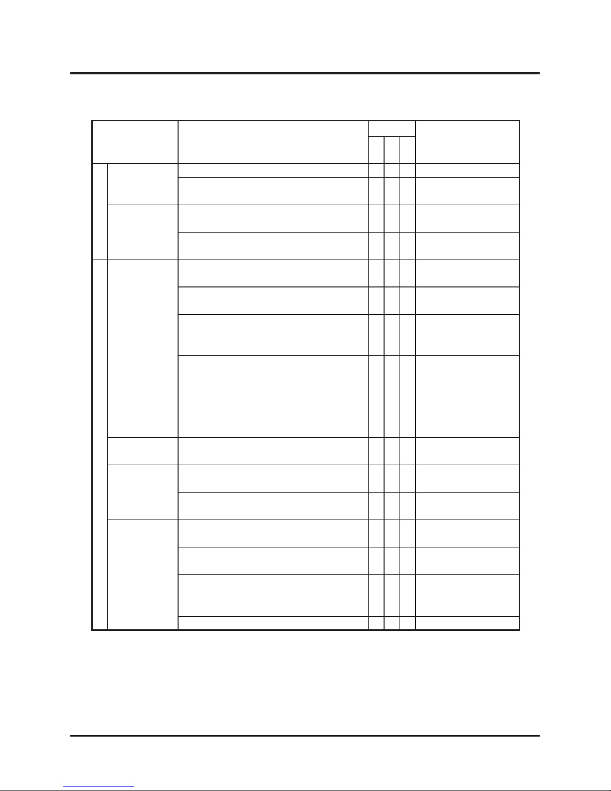
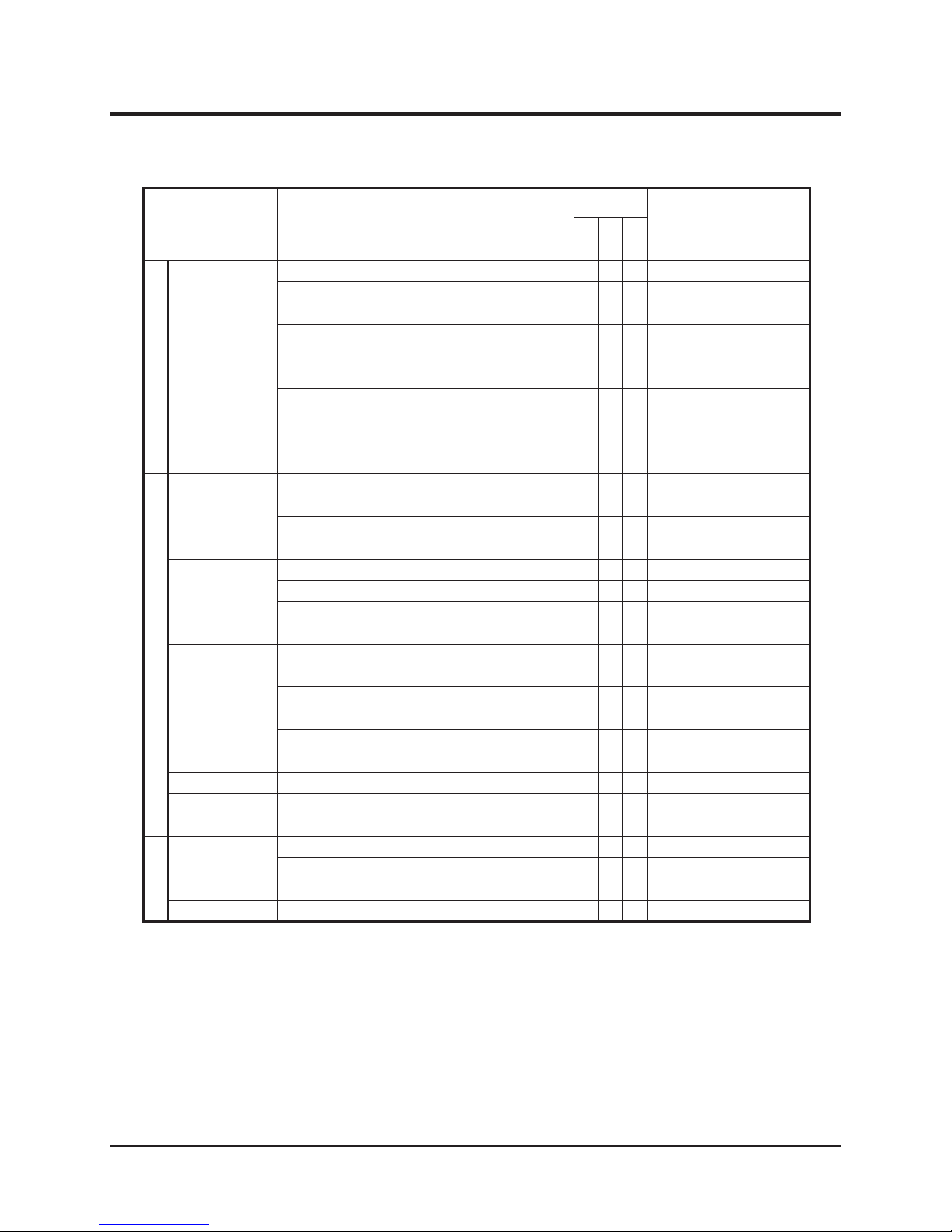
Maintenance Schedule
• Perform a pre-startup inspection (PSI) before each use, a monthly inspection once a
month, and a yearly inspection once a year.
• Some maintenance procedures described below may require special knowledge
or tools and instruments. Contact your Canycom representative to perform such
procedures.
Item Description
Schedule
Note
PSI
Mon
Year
Engine
General
Starting
Engine shall start easily without making any
irregular noise.
√ √ √
Running
Engine speed shall be set properly at idle
and at full without loading. Engine shall stay
running smoothly.
√ √
Contact your Canycom
r e pr es e n t a t iv e f o r
inspection.
When accelerating engine, throttle lever shall
move smoothly, and engine shall accelerate
smoothly without stopping or knocking.
√ √ √
Exhaust
Warm up engine thoroughly, and observe
exhaust sound and gas from idle to fast
speed; exhaust sound shall be normal and
no smoke shall be observed.
√ √ √
There shall be no leak in exhaust system or
mufer.
√ √
A i r
Cleaner
Air cleaner case shall not be deformed or
cracked. Case lid and connecting air hose
shall be rmly in place.
√ √
Cleaner element shall be in good shape
without damage or excessive dust.
√ √
Cleaning/Repl a c ing:
Page 39
Fasteners
Bo lts and nu ts fastening cylinder head,
intake and exhaust manifolds shall be tightly
fastened.
* this may be skipped if there is no gas or
water leak found in these areas.
√
Page 38
-29-
Maintenance 5
Item Description
Schedule
Note
PSI
Mon
Year
Engine
General
V a l v e
Clearance
Valve clearance shall be correct.
* this may be skipped if there is no noise due
to incorrect valve clearance, and engine
runs normally.
√
Contact your Canycom
r e pr es e n t a t iv e f o r
inspection.
Compression
Compression shall be normal
* this may be skipped if running and exhaust
condition i s n o r m a l at idle and under
acceleration.
√
Contact your Canycom
r e pr es e n t a t iv e f o r
inspection.
E n g i n e
Mount
Engine base s hall be fr e e of cracks o r
deformation.
√ √ √
Mounting bolts and nuts shall not be loose or
missing.
√ √ √
L u b r i c a t i o n
System
Oil shall be clean and at correct level.
√ √ √
Inspecting/Changing:
Page 37
No noticable oil leak shall be found in head
cover, oil pan, or pipes.
√ √ √
Fuel System
There shall not be any leak in fuel tank,
hoses, or pipes.
√ √ √
Fuel hose s shall be f r ee of dam a g e or
deterioration.
√ √ √
Fuel lter shall not be excessively dirty or
clogged.
√ √
There shall not be sediments or water in the
fuel tank.
√ √
Electrical System
S p a r k
Plugs
Electrodes shall not be worn, and there shall
not be excessive carbon deposit.
√
Cleanin g /Repla c i ng:
Page 40
C h a r g e
System
Battery shall be charged.
√
Contact your Canycom
r e pr es e n t a t iv e f o r
inspection.
Battery
Battery electrolyte level shall be correct.
√ √
I n s p e c t i n g / F i l l i n g :
Page 53
Terminals shall be free of marked corrosion
and are tightly secured.
√ √
Wiring
Connections shall be securely connected.
√ √
Wiring shall be free of damages.
√ √
Drivetrain
Clutch
Clutc h sha l l not make noise and s hall
disengage completely when operated at idle.
√ √
Clutch shall not slip and engage smoothly.
√ √
Page 39
Maintenance
-30-
5
Item Description
Schedule
Note
PSI
Mon
Year
Drive Train
Drive Belts
Belt tension shall be properly adjusted.
√ √
Inspecting/Adjusting:
Page 46
Belt shall be free of damages, excessive
wear, or dirt; shall be free of oil or grease.
√ √
Transmission
Irregular noise or overheating shall not be
observed.
√ √ √
Oil shall be clean and lled to a proper level.
√ √
Replacing: Page 44
The re shall not be oil leak in or a round
transmission.
√ √
HST Pump
Drive the machine forward and backward,
turn left and right in both directions; machine
shall move normally and free of irregular
noise or overheating.
√ √ √
Hydraulic uid shall be lled to a proper
level.
√ √
Inspecting/Changing:
Page 42
Hydraulic uid shall be clean and free of dirt
or contamination.
√ √
Inspecting/Changing:
Page 42
There shall be no uid leak in or around uid
tank.
√ √
Linkage
Rods, links, and wires in linkage shall be free
of deformation or damage.
√ √
Connections shall be free of looseness,
excessive play, or missing cotter pins.
√ √
Undercarriage
W h e e l s
S p r o c k e t s
Idlers
Sh all be free of cr acks, defromation, or
excessive wear.
√ √ √
There shall not be excessive play in axle.
Irregular noise or overheating shall not be
observed when traveling.
√ √ √
Mounting bolt or nut shall not be loose or
missing.
√ √ √
There shall be no oil leak in or around axle.
√ √
Tracks
There shall not be marked cut, deterioration,
or wear.
√ √ √
Track shall be properly tensioned; shall not
be too loose or too tight.
√ √ √
Adjusting: Page 41
Tension bolt shall be free of deformation or
corrosion.
√ √ √
Page 40
-31-
Maintenance 5
Item Description
Schedule
Note
PSI
Mon
Year
Brake System
Parking Brake
Parking brake shall work properly.
√ √ √
Adjusting: Page 47
Park i n g brake shall be able t o hold the
machine on a 20-degree slope.
√ √
Linkage
Rods, links, and wires in linkage shall be free
of deformation or damage.
√ √
Connections shall be free of looseness,
excessive play, or missing cotter pins.
√ √
Hydraulic System
H y d r a u l i c
Pump
There shall be no leak in or around hydraulic
pump.
√ √
Fastening bolts and nuts shall not be loose
or missing.
√ √
No irregular vibration, noise, or heat shall
be observed wh en hydrauli c pump is in
operation.
√ √
Amount and pressure of discharge under
loa d shall be wi thin the stan dard range
specied by the manufacturer.
*this may be skipped if irregular vibration,
nois e, o r he at d e scr i bed abo v e i s no t
observed.
√
H y d r a u l i c
Valve
There shall be no leak in or around hydraulic
valve.
√ √
H y d ra u li cs
Belt
Belt tension shall be properly adjusted.
√ √
Inspecting/Adjusting:
Page 52
Belt shall be free of damages, excessive
wear, or dirt; shall be free of oil or grease.
√ √
Plumbing
Plumbing shall be free of cracks, damages,
twists, or deterioration.
√ √
There shall be no leak in pipes, hoses, joints,
or seals.
√ √
Plumbing shall be mounted properly, and
fastening bolts and nuts shall not be loose or
missing.
√ √
Breather shall not be clogged.
√ √
Page 41
Maintenance
-32-
5
Item Description
Schedule
Note
PSI
Mon
Year
Hydraulic System
H y d r a u l i c
Cylinder
Shall work smoothly.
√ √
There shall be no leak when extending and
contracting cylinder.
√ √
Extend cylinder fully under load and hold.
Stroke shall be within the range specied by
manufacturer.
√
Cylinder tube and rod shall be free of dents,
cracks, bends, or scratchs.
√ √
Cyli n d er mounting pins shall b e free of
damages or excessive wear.
√ √
Body, Chassis, Loading Deck
C h a s s i s
Frame
Sh all be free of cr acks, deformation, or
corrosion.
√ √
Fastening bolts or nuts shall not be loose or
missing.
√ √
Body Panels
Shall be free of cracks or deformation.
√ √
Doors shall open, close, and lock properly.
√ √ √
Fastening bolts or nuts shall not be loose or
missing.
√ √
Loading Deck
Bucket
Loading deck shall be raised and lowered
smoothly.
√ √
Sh all be free of cr acks, deformation, or
corrosion.
√ √
Fastening bolts or nuts shall not be loose or
missing.
√ √
Safety Prop
Safety prop shall be free of any deformation.
√ √
Labels
Warning labels and instruction plates shall
be clean, legible, and free of damages.
√ √ √
Safety Devices
Work Lamp
Work lamp shall work.
√ √ √
Lamp lens shall be free of cracks or chipping
and water shall not be in the lamp.
√ √
Horn
Horn shall work.
√ √ √
Page 42

-33-
Maintenance 5
List of Fluids and Lubricants
Item Schedule Grade Cap. Ref.
Fuel As needed. Automotive Unleaded
Gasoline
20 L
(5.28 US Gal.)
Page 15
Engine Oil
Fill
Inspect daily. Fill as needed.
Change
Initially - After 8 hours of use.
Every 50 hours afterwards.
Engine Oil
API rating: SE or better.
SAE rating: 10W-30
1.4 [1.55]L
(1.48 [1.64]
US qt.)
Page 37
Transmission Oil
Change
Initially - After 50 hours of use.
Every 100 hours afterwards.
Gear Oil
API rating: GL-4 or 5
SAE rating: 80
2.0L
(2.11 US qt.)
Page 44
HST Fluid Change
Initially - After 50 hours.
Every 500 hours afterwards.
High viscosity index
hydraulic uid, ISO VG46
23L
(6.08US Gal.)
Page 42
Battery Electrolyte
Inspect daily. Distilled Water
- Page 53
* Numbers in the square brackets [ ] indicate the capacity including the oil lter cartridge.
Greasing and Lubrication Points
Point Schedule Grade Cap. Ref.
Greasing Points
6 months after the purchase.
Every 6 months afterwards.
Chassis Grease
- Page 51
Lubrication Points
6 months after the purchase.
Every 6 months afterwards.
Gear Oil
API rating: GL-4 or 5
SAE rating: 80
- Page 51
Page 43

Maintenance
-34-
5
List of Consumables and Spares
Item Part No. Schedule Qty. Ref.
Engine
Air Cleaner Element -
Inspect every 50 hours.
Replace if defective.
1 Page 39
Oil Filter -
Initially: 50 hours.
Every 150 hours afterwards.
1 Page 39
Spark Plug(NGK BP6ES) - Replace if defective. 2 Page 40
Drive Train
Drive Belt (SB48)
08521500048
Replace if defective. 2 Page 46
Track
35702021000
Replace if defective. 2 Page 41
Brake Lining
73014007000
Replace if defective.
(Replace in pairs)
2 Page 47
Suction Filter
36636029000
Every 500 hours. 1 Page 43
Line Filter
35706161000
Every 500 hours. 1 Page 43
Hydraulic Hose (HST)
-
Every 2 years
or if defective.
1
Electrical System
Battery (40B19R)
37053901000
Replace if defective. 1 Page 53
Fuse 5A - Replace if defective. 3 Page 55
Fuse 30A - Replace if defective. 1 Page 55
Hydraulic System
Hydraulics Belt (LA35)
08511600035
Replace if defective. 1 Page 52
Hydraulic Hose (Dump)
-
Every 2 years
or if defective.
1
Hydraulic Hose (Oil Cooler)
-
Every 2 years
or if defective.
1
• Rubber products such as the hydraulic hose deteriorate over time. Replace them
every 2 years.
NOTE
Page 44
-35-
Maintenance 5
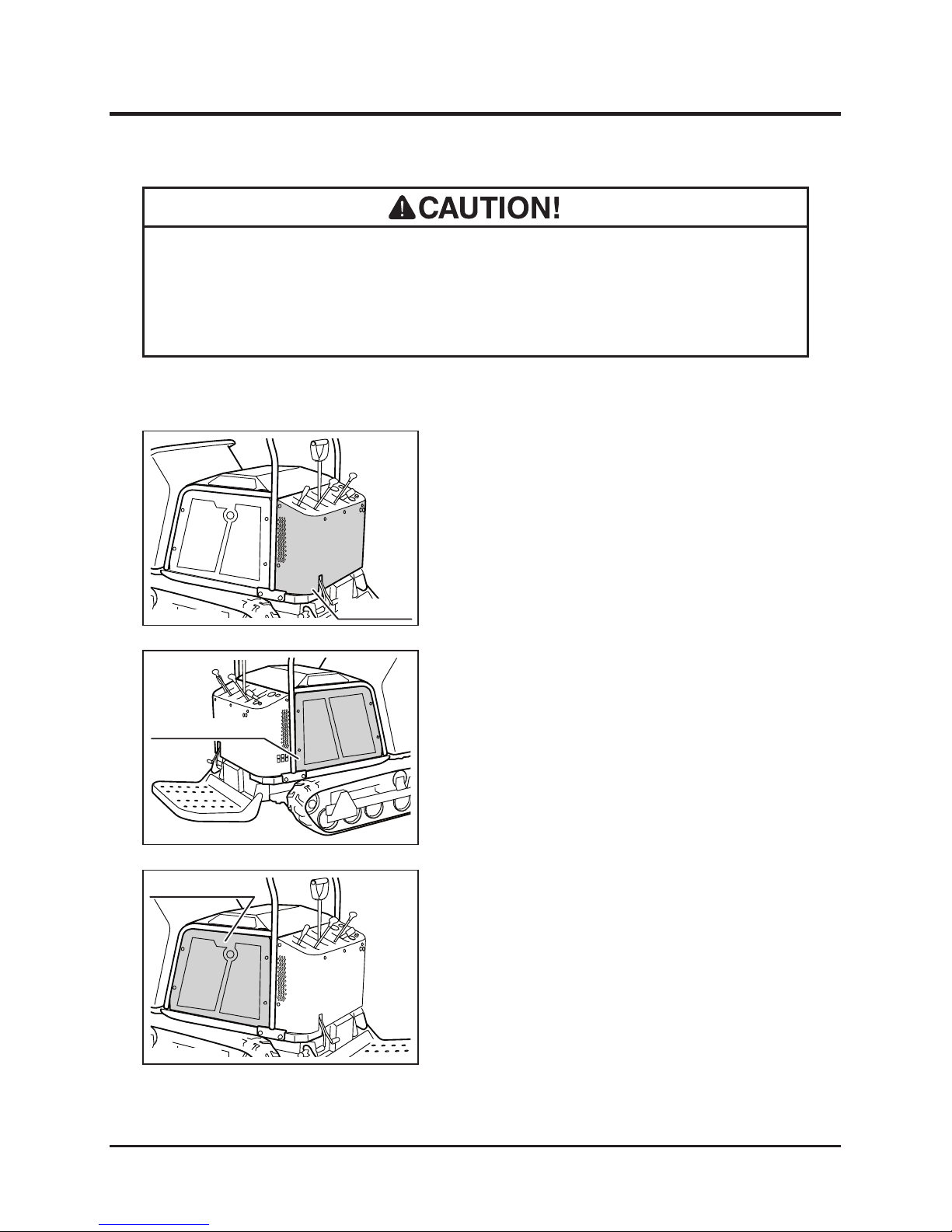
Removing the Back Panel
1. Unfasten (9) bolts to remove the back panel.
Engine Compartment
Removing and Installing Body Panels
• Cut or pinch hazard exists when removing or installing body panels; beware of
sharp edges and pinch points.
• Make certain to reinstall panels after removing for repairs or inspection.
Installing the Back Panel
1. Hold the back panel in place and fasten bolts
to install the back panel.
3570M-0505-010E
Back Panel
Removing the Side Panel (Right)
1. Unfasten (4) bolts to remove the right side
panel.
Installing the Side Panel (Right)
1. Hold the right side panel in place and fasten
bolts to install the right side panel.
3570M-0505-020E
Side Panel (Right)
Removing the Side Panel (Left)
1. Unfasten (4) bolts to remove the left side
panel.
Installing the Side Panel (Left)
1. Hold the left side panel in place and fasten
bolts to install the left side panel.
3570M-0505-030E
Side Panel (Left)
Page 45
Maintenance
-36-
5
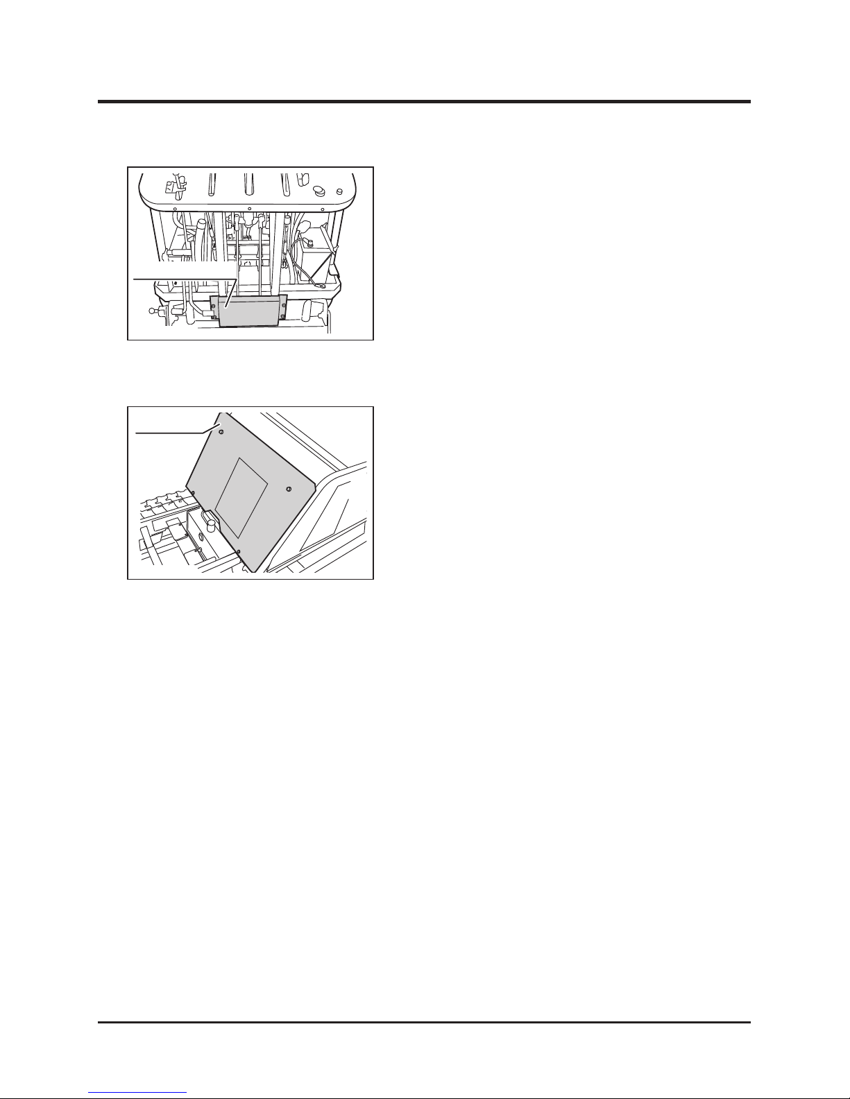
Removing the Control Rod Cover
1. Remove the back panel. (Page 35)
2. Unfasten (4) bolts to remove the control rod
cover.
Installing the Control Rod Cover
1. Hold the control rod cover in place and
fasten bolts to install the control rod cover.
2. Install the back panel. (Page 35)
3570M-0505-040E
Control Rod Cover
Removing the Front Panel
1. Raise the bucket.
2. Hold the bucket with the safety prop.
3. Unfasten (4) bolts to remove the front panel.
Installing the Front Panel
1. Hold the front panel in place and fasten bolts
to install the front panel.
2. Undo the safety prop and lower the bucket.
3570M-0505-050E
Front Panel
Page 46
-37-
Maintenance 5
Engine
Engine Oil
• Always stop the engine before servicing.
• An engine that has been running is very hot. Allow the engine to cool before
servicing, or severe burns may result.
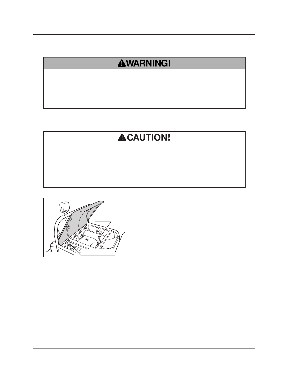
1. Park the machine on a level surface.
2. Open the engine hood and hold it in place
with the engine hood stay.
• Dispose of the drained oil properly.
• Make certain to ll the engine with correct grade of oil to the specied level.
Insufcient amount or wrong grade of oil reduces performance and may cause
permanent damage to the engine.
Inspecting
3570M-0506-010E
Engine Hood Stay
Dipstick
Page 47
Maintenance
-38-
5
1. Remove the oil ller cap.
2. Follow the instructions in the Operator's
Manual for the engine to ll oil.
3. Check oil level.
4. Put the oil ller cap back in place and tighten
it securely.
Filling
1. Have an appropriate oil drain pan.
2. Remove the drain plug to drain oil.
3. Put the drain plug back in place and tighten it
securely.
4. Fill oil.
Changing
3570M-0506-030E
Oil Filler Cap
• O i l C a paci t y: 1 .4L( 1 .48 U S qt s .) [ 1.55 L
(1.64 US qts.) when changing the oil lter
cartridge.
• Removing the oil filler cap helps drain oil
faster.
3570M-0506-020E
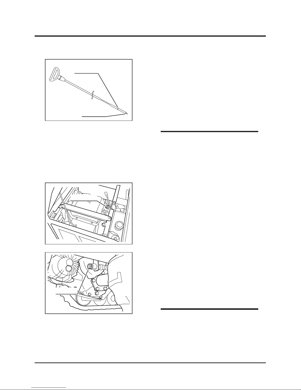
Upper Limit
Lower Limit
3570M-0506-040E
Drain Plug
• To obtain correct reading, check oil level
before starting, or wait about 10 minutes
after stopping the engine to al low oil to
drain back to the oil pan.
• Always check oil level on a level surface.
NOTE
3. Pull out the dip stick. Wipe oil off of the
dipstick with clean cloth.
4. Insert the dipstick and pull it out again.
5. Check oil level. Oil level should be between
the two dimples indicating the upper and
lower limits. If the level is low, ll oil.
6. Visually insp ect oil. If oil is dirty or its
viscosity is not normal, change it.
NOTE
Page 48
-39-
Maintenance 5
Oil Filter
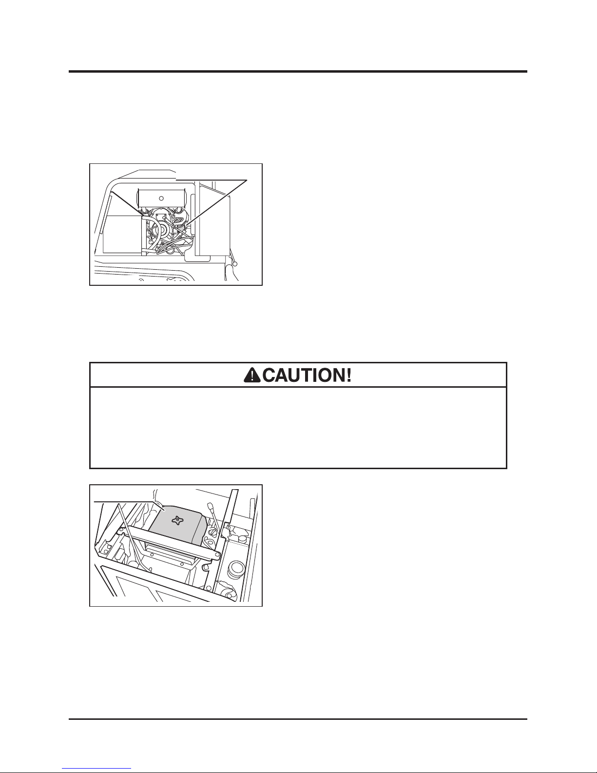
1. Remove the left side panel and back panel.
(Page35)
2. Drain oil. (Page 37)
3. Follow the instructions in the Operator's
Manual for the engine to change the oil
lter cartridge.
4. Fill oil. (Page 37)
5. Run the engine and make sure that there is
no leak at the lter mount.
6. Install panels back in place.
3570M-0506-060E
Oil Filter Cartridge
Air Cleaner
• Clean air cleaner element regularly. Dirty cleaner element reduces engine
performance and life.
• Replace the cleaner element if damaged.
1. Open the engine hood and hold it in place
with the engine hood stay.
2. Remove the air cleaner lid.
3570M-0506-070E
Air Cleaner Lid
Page 49
Maintenance
-40-
5
3570M-0506-080E
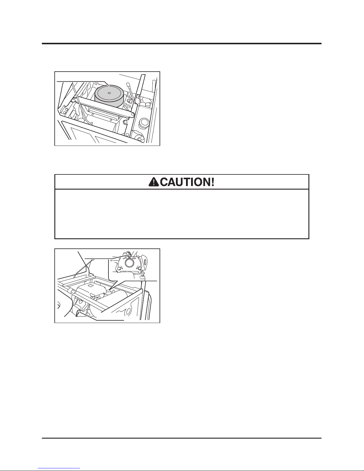
Air Cleaner Element
Spark Plugs
1. Open the engine hood and hold it in place
with the engine hood stay.
2. Remove the spark plug caps and the spark
plugs. Spark pulgs are located in the front
and rear of the engine.
3. Follow the instructions in the Operator's
Manual for the engine to inspect, clean, or
change the spark plugs.
4. Install the spark plugs and the spark plug
caps. Undo the engine hood stay and close
the engine hood.
• Never pull ignition cable when removing a spark plug cap. Conductor in the
cable may be severed or damaged.
• If a spark plug is damaged, replace it with a new one.
3570M-0506-090E
Spark Plug
Spark Plug
3. Remove the air cleaner element.
4. Follow the instructions in the Operator's
Manual for the engine to clean or change
the air cleaner element.
5. Put the air cleaner element and air cleaner
lid back in place.
6. Undo the engine hood stay and close the
engine hood.
Page 50
-41-
Maintenance 5
Drive Train
• Stop the engine when servicing the drive train.
• Allow the machine to cool off before servicing. The engine is very hot after
operation and may pose a burn hazard.
Tracks
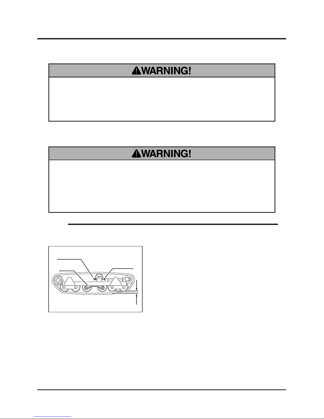
1. Hoist one side of the machine so that the
machine is laterally parallel to the ground.
(Page 63)
2. Inspect the clearance between the track and
the second wheel to be between 20 and
30mm (0.79" - 1.18"). Adjust the tracks if the
clearance is not within this range.
3. Lower the machine.
Inspecting
• Support the machine securely on a rm, level surface with jack stands when
servicing.
• Make certain to adjust the track tension properly. Inproperly tensioned tracks
may wear or come off, resulting in property damage, serious injury or death.
3570M-0507-010E
20 - 30mm (0.79" - 1.18")
Lock Nut
Adjust Bolt
Swing
• The track stretches during its use-life. Inspect and adjust regularly.
NOTE
Page 51
Maintenance
-42-
5
Adjusting
1. Jack up and support the machine parallel to
the ground.
2. Loosen the lock nut.
3. Adjust the track with adjust bolt so that the
clearance between the track and the wheels
at the furthest are between 20 and 30mm
(0.79" - 1.18").
4. Tighten the lock nut
5. Lower the machine.
HST (HydroStatic Transmission) Fluid
• Dispose of the drained uid properly, according to the national and local regula-
tions.
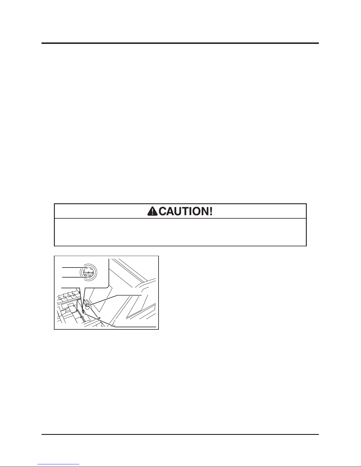
3570M-0507-020E
Filler Cap
Upper Limit
Lower Limit
Oil Level Window
1. Park the machine on a level ground.
2. Lift the bucket and hold the bucket with the
safety prop. (Page 26) Lock the dump lever
with lock plate.
3. Visually inspect the oil level window.
4. If the level is low, open the ller cap and ll
uid. Put the ller cap back in place.
5. Undo the safety prop. Lower the bucket.
Inspecting/Filling
Page 52
-43-
Maintenance 5
Line Filter and Suction Filter
• Burn hazard; pay special attention when handling the hydraulic uid. Hot uid
may cause burns.
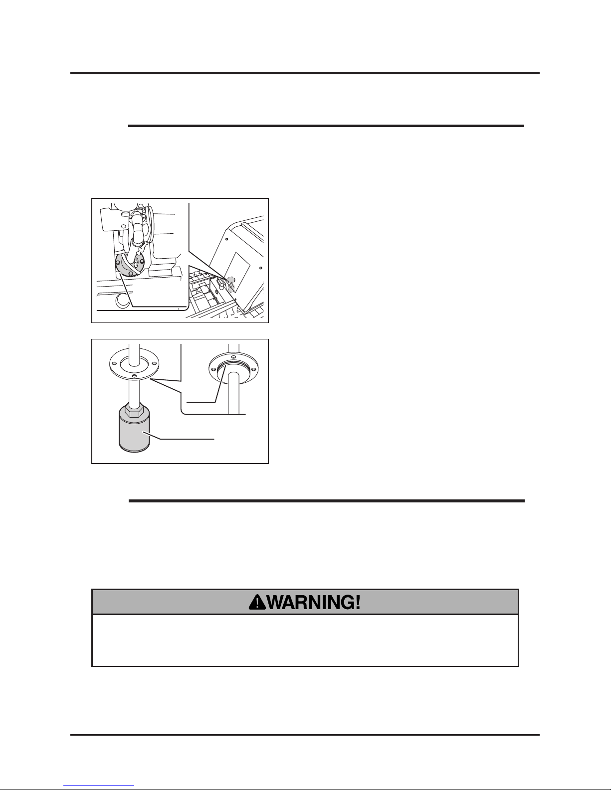
1. Remove the right side panel (Page 35).
2. Drain HST uid. (Above, "Changing")
3. Remove the line lter cartridge with an oil
lter wrench.
4. Have a new line lter cartridge. Apply clean
hydraulic uid (oil) on the cartridge oil seal
evenly.
5. Screw in the new line lter cartridge. Tighten
it by hand until the cartridge is rmly in place.
6. Fill HST uid.
7. Start the engine and engage the clutch to
circulate the uid. Watch for a leak.
8. Install the right side panel. (Page 35)
3570M-0507-040E
Line Filter Cartridge
3570M-0507-030E
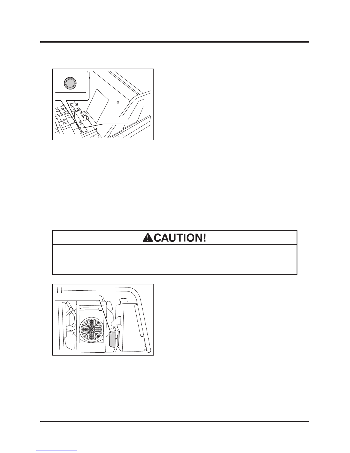
Drain Plug
1. Have an appropriate oil drain pan.
2. Lift the bucket and hold the bucket with the
safety prop. (Page 26) Lock the dump lever
with lock plate.
3. Remove the drain plug to drain uid.
4. Wipe the drain plug and drain hole clean.
Put the drain plug back in place. Tighten it
securely.
5. Open the ller cap to ll uid. Put the ller
cap back in place.
6. Undo the safety prop and lower the bucket.
7. Start the engine and engage the clutch to
circulate the uid.
8. Inspect the uid level.
Changing
Changing Line Filter
Page 53
Maintenance
-44-
5
1. Park the machine on a level ground.
2. Lift the bucket and hold the bucket with the
safety prop. (Page 26) Lock the dump lever
with lock plate.
3. Remove the front panel. (Page 36)
4. Undo the bolts and remove the suction lter
mount.
3570M-0507-050E
Suction Filter
Mount
• Replace both the line lter cartridge and the suction lter element when hydraulic
uid is changed.
NOTE
Changing Suction Filter
Transmission Oil
• Always park the machine on a level surface and block the tracks with chocks
when working under the machine.
• Replace both the line lter cartridge and the suction lter element when hydraulic
uid is changed.
• Do not use the lter wrench when tightening the lter cartridge. Tighten it by hand.
NOTE
5. Unfasten the suction lter with a wrench and
install a new lter. Tighten it securely.
6. Coat the O-ring with hydraulic uid evenly
and insert the suction lter mount inthe tank.
Make sure to insert it straight so that the
O-ring does not get out of the groove. Fasten
the suction lter mount with bolts.
7. Install the front panel. (Page36)
8. Undo the safety prop. Lower the bucket.
3570M-0507-180E
Suction Filter
O-ring
Page 54
-45-
Maintenance 5
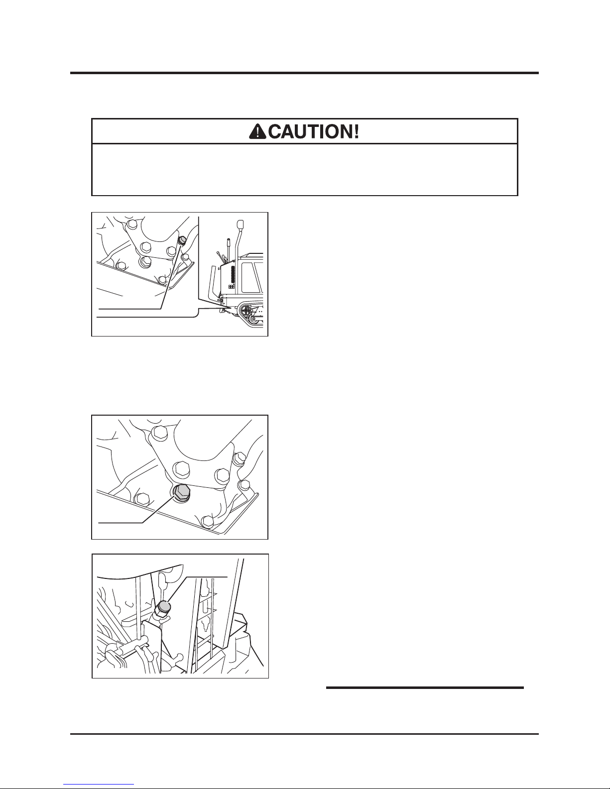
1. Have an appropriate oil drain pan.
2. Remove the back panel. (Page 35)
3. Remove the drain plug to drain the oil.
4. Put the drain plug back in place and tighten it
securely.
• Oil Capacity: 2.0L (2.11 US qts.)
1. Park the machine on a level ground.
2. Remove the inspection plug and inspect if
the oil level is at the inspection hole. Fill oil if
the level is low.
3. Visually inspect the condition of the oil. If
dirty, change it.
4. Visually inspect the seal washer on the
inspection plug.
5. Cl e a n t h e i n s p e c t i o n p l u g a n d s e a l
washer. Put the inspection plug back in the
inspection hole and tighten it securely.
3570M-0507-060E
Inspection Plug
1. Remove the back panel. (Page 35)
2. Remove the ller cap and ll a sufcient
amount of oil.
3. Inspect the oil level.
4. Put the ller cap back in place.
5. Install the back panel. (Page 35)
3570M-0507-070E
Drain Plug
Inspecting
Draining
3570M-0507-080E
Filler Cap
NOTE
• Dispose of the drained oil properly, according to the national and local regula-
tions.
Filling
Page 55
Maintenance
-46-
5
Drive Belts
1. Remove the left side panel (Page 35)
2. Move the clutch lever to [ (disengaged)]
position.
3. Visually inspect the belts. Replace the belt if
damaged.
4. Install the left side panel back in place.
(Page 35)
Inspecting
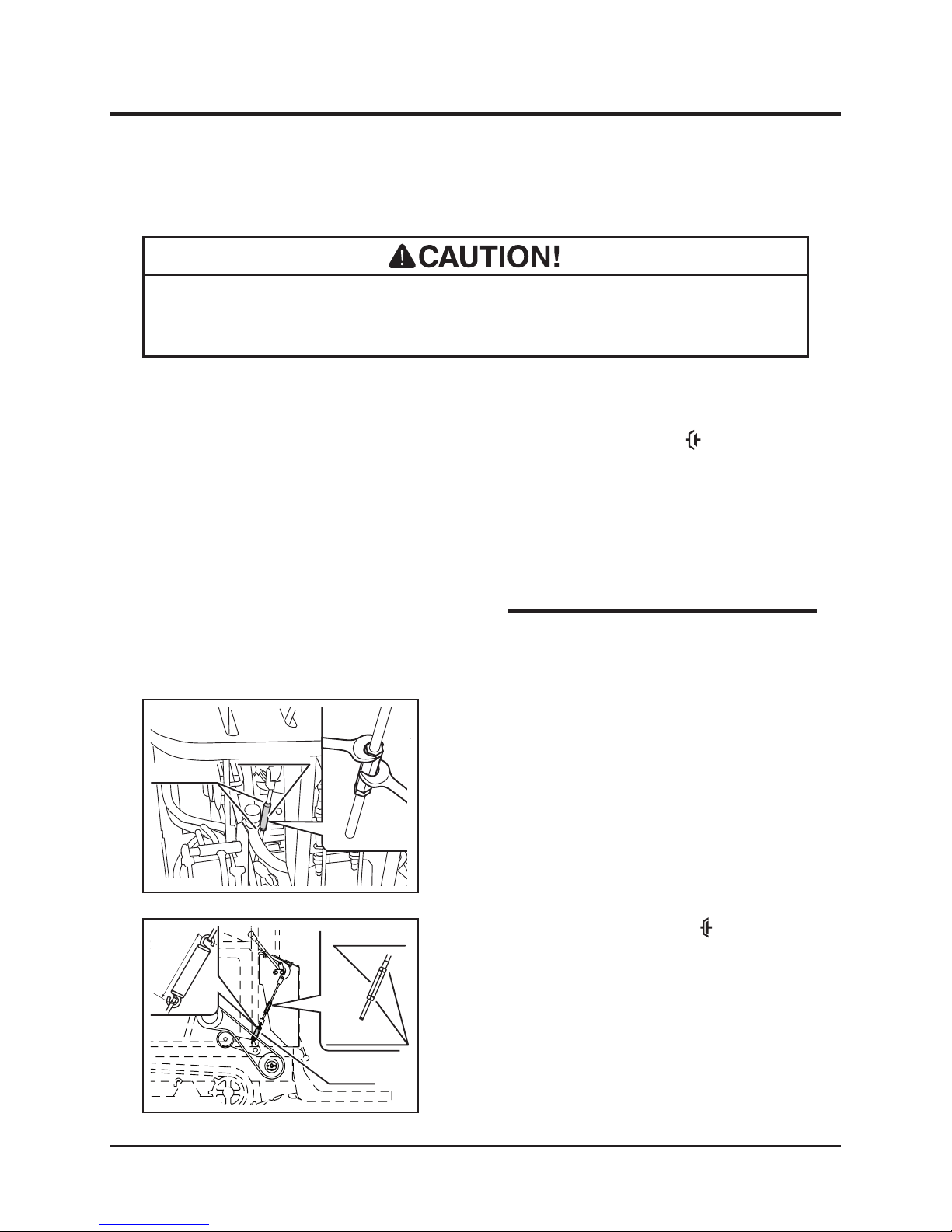
3570M-0507-100E
Spring
Lock Nuts
Turnbuckle
4.37" - 4.49"
• Adj u st b elt ten s ion p rop e rly. Inp r ope r ly t ens i one d bel t s m a y r e duc e
performance and its service life.
1. Remove the back and the left side panels.
(Page 35)
2. With two wrenches, loosen the lock nuts that
lock the turnbuckle on the clutch linkage.
Adjusting
3570M-0507-090E
Turnbuckle
Lock Nuts
• Contact your CANY COM repre sentativ e
when the belt needs to be replaced.
NOTE
3. Move the clutch lever to [ (engaged)]
position.
4. Adjust the turnbuckle so that the inside
dimention between t he spr ing ho oks is
between 111 and 114 mm (4.37" and 4.49").
5. Tighten the lock nuts with two wrenches.
6. Install the back and the left side panels back
in place. (Page 35)
Page 56
-47-
Maintenance 5
Belt Stoppers
1. Remove the left side panel. (Page 35)
2. Move the clutch lever to [ (engaged)]
position.
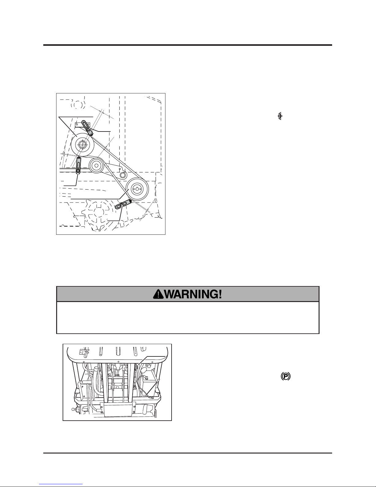
3. Lo os e n the b o lt s t ha t f as t en th e b el t
stoppers. Adjust the belt stoppers so that the
gap A, the distance between the belt stopper
pins and the belt, is 5-6mm (0.20"-0.24"),
and the gap B, the distance between the
center of the engine pulley and the line
connecting the belt stopper pins by the
engine pulley, is 10-20mm (0.39"-0.79").
Tighten the bolts securely.
4. Start the engine and observe if the belt runs
smoothly without rubbing the pins. Stop the
engine.
5. Install the left side panel in place. (Page 35)
Adjusting
3570M-0507-110E
Engine Pulley
B
A
A
A
Transmission Pulley
Bolt
Bolt
Bolt
3570M-0507-120E
Spring
• Always keep brake adjusted for maximum performance. Inproperly adjusted
brake may result in property damage, serious injury, or death.
Parking Brake
1. Make certai n the control stick is in the
neutral and centered position.
2. Move the brake lever to [ (engaged)]
position.
3. Remove the back panel. (Page 35)
Inspecting
Page 57
Maintenance
-48-
5
Adjusting
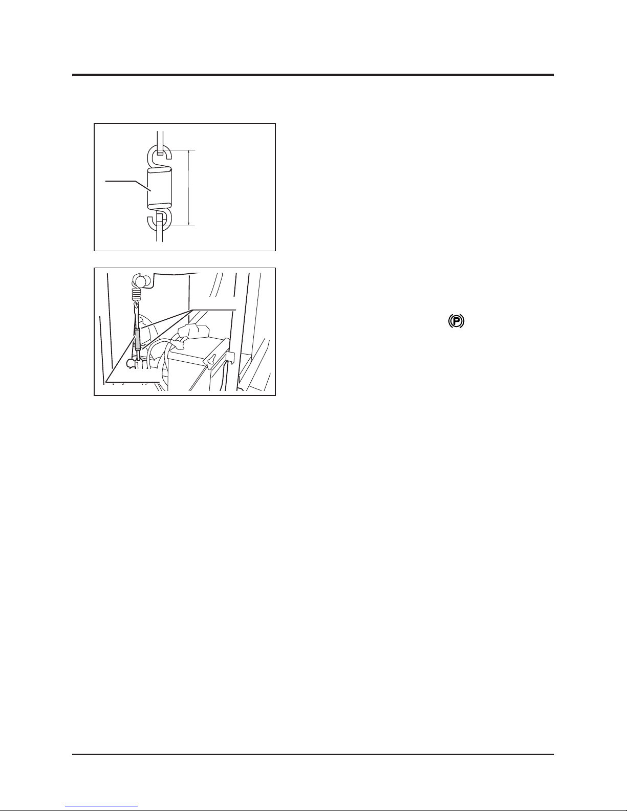
3. Locate the spring on the brake linkage.
Measure the distance between the spring
hooks; the distance shall be between 66 and
68mm (2.60" and 2.68" respectively).
4. In sta ll th e b a ck pa nel ba ck in pl a ce .
(Page35)
3570M-0507-130E
Spring
66 - 68mm
1. Make certain the control stick is in the
neutral and centered position.
2. Move the brake lever to [ (engaged)]
position.
3. Remove the back panel. (Page 35)
4. Loosen the lock nuts.
5. Adjust the turnbuckle so that the distance
be t we e n t h e s pr i ng h oo k s s h al l b e
between 66 and 68mm (2.60" and 2.68"
respectively)
6. Tighten the lock nuts securely.
7. Install the back panel back in place. (Page
35)
3570M-0507-140E
Lock Nuts
Turnbuckle
Page 58
-49-
Maintenance 5
Control Stick
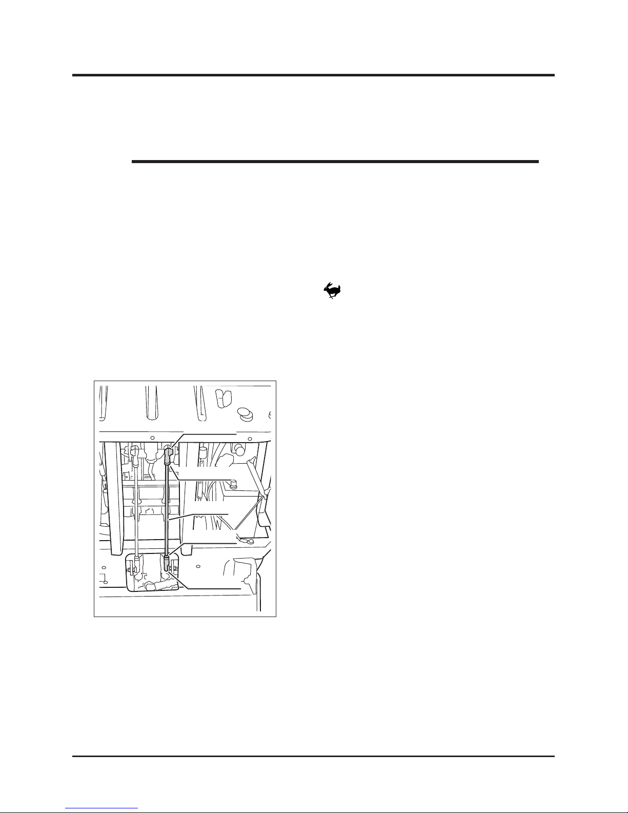
1. Start the engine and increase the engine
sp ee d by mo vi ng th e th ro t tl e le ver t o
[ (fast)] position.
2. Operate the machine on a level surface and
release the control stick; if the track moves
forward or backward, the control stick needs
to be adjusted.
3570M-0507-150E
Lock Nut (A)
Lock Nut (A)
Rod End (C)
Rod End (C)
Rod (B)
• Control stick is properly adjusted at the time of shipment. Adjustment is needed
only when the transmission, the control stick itself, or its linkage is replaced or
dismantled.
NOTE
Inspecting
3. Remove the back panel and the control rod
cover. (Page 35, 36)
4. Loosen the lock nuts (A).
5. Rotate the rod (B) until the right track does
not move.
- When the track moves forward, turn the rod
so that the distance between the rod ends
(C) becomes longer.
- When the track moves backward, turn the
rod so that the distance between the rod
ends (C) becomes shorter.
6. Tighten the lock nuts (A) securely.
Adjusting - When the Right Track Moves
Page 59
Maintenance
-50-
5
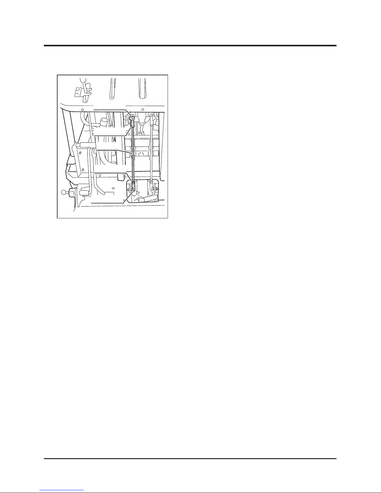
7. Loosen the lock nuts (D).
8. Rotate the rod (Е) until the left track does not
move.
- When the track moves forward, turn the rod
so that the distance between the rod ends
(F) becomes longer.
- When the track moves backward, turn the
rod so that the distance between the rod
ends (F) becomes shorter.
9. Tighten the lock nuts (D) securely.
10. Install control rod cover and back panel.
(Page 36, 35)
Adjusting - When the Left Track Moves
3570M-0507-160E
Lock Nut (D)
Lock Nut (D)
Rod End (F)
Rod End (F)
Rod (E)
Page 60
-51-
Maintenance 5
Greasing and Lubricating
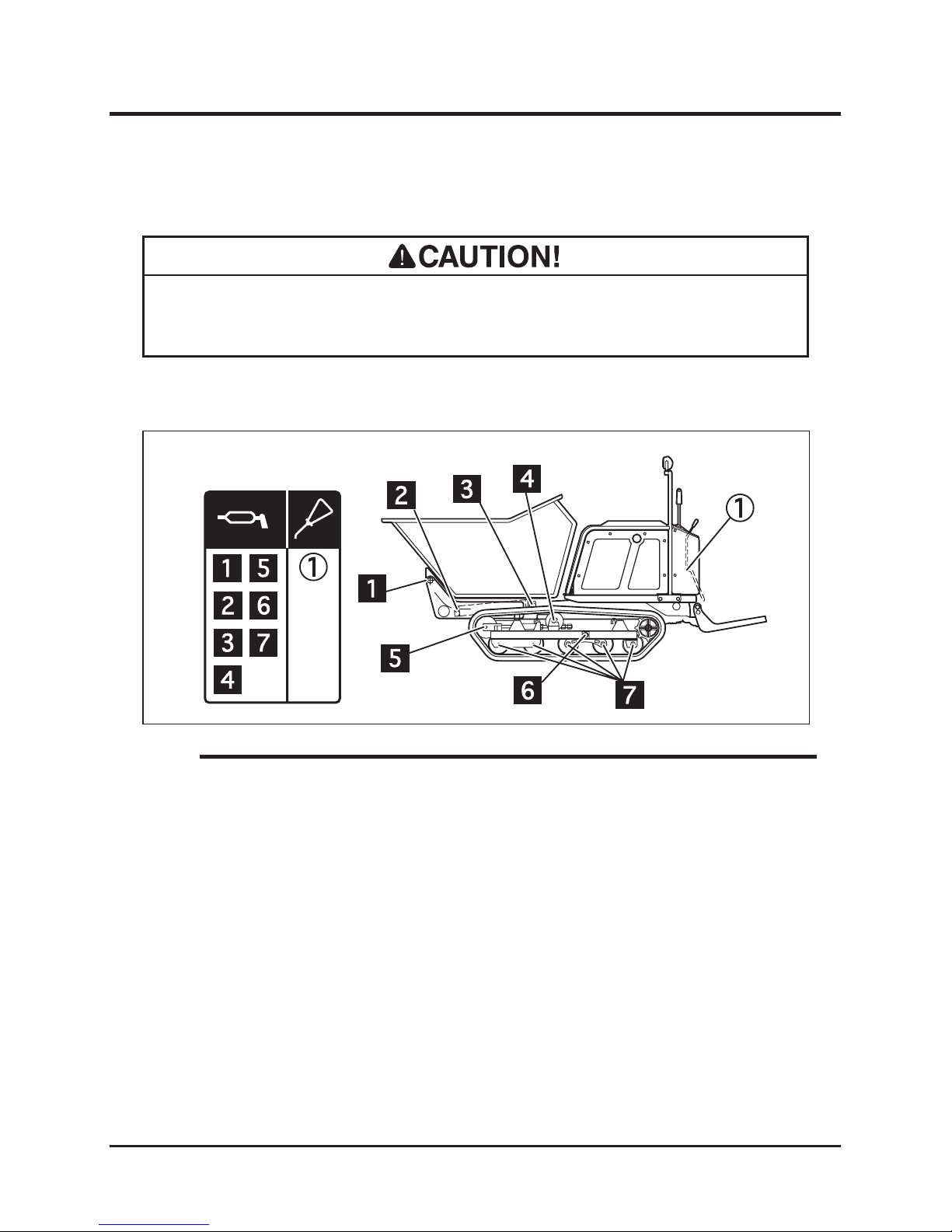
• Follow the maintenance schedule to grease and lubricate the machine. Lack of
grease or lubrication may result in rust, excessive wear or seizure.
3570M-0507-170E
Greasing
Points
Lubricating
Points
1. Grease and lubricate the greasing and lubricating points.
• Grease and lubricant to use: Page 33
• When using a manual grease gun, pump 5-6 times. When the handle of the gun
becomes heavy, stop pumping immediately.
• When using a pneumatic grease gun, pump it for a few seconds.
NOTE
Page 61
Maintenance
-52-
5
Hydraulic System
Hydraulics Belt
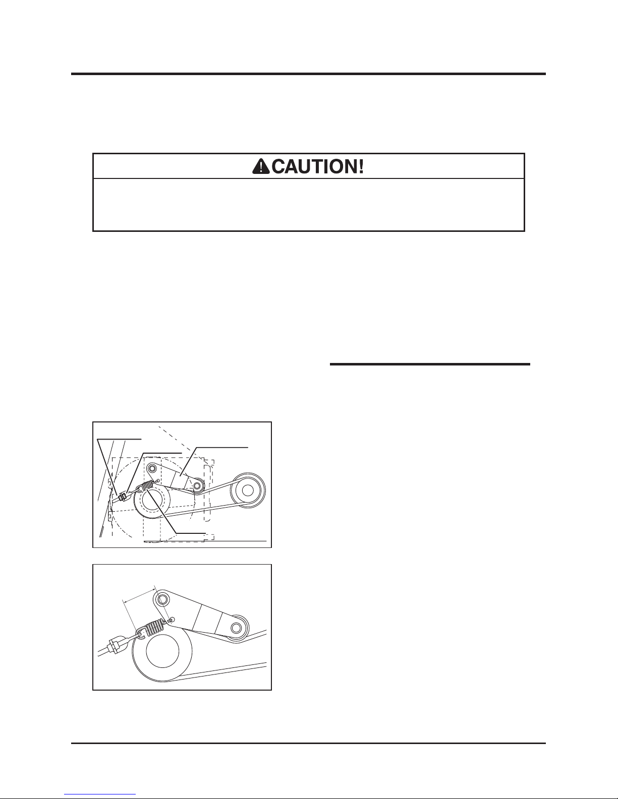
1. Remove the left side panel. (Page 35)
2. Visually inspect the belt. Replace the belt if
damaged.
3. Install the left side panel back in place.
(Page 35)
3570M-0508-010E
Tension Arm
Lock Nut
Adjust Nut
Spring
3570M-0508-020E
65 - 68mm
Inspecting
• Adj u st b elt ten s ion p rop e rly. Inp r ope r ly t ens i one d bel t s m a y r e duc e
performance and its service life.
Adjusting
• Contact your CANY COM repre sentativ e
when the belt needs to be replaced.
NOTE
1. Locate the tension arm spring. Loosen the
lock nut.
2. Adjust the adjust nut so that the inside
dimension between the spring hooks is
between 65 and 68 mm (2.56" and 2.68").
3. Tighten the lock nut.
4. Install the left side panels back in place.
(Page 35)
Page 62
-53-
Maintenance 5
Electrical System
Battery
• Explosion hazard. Keep open ame or spark away from battery. Hydrogen gas
generated during charging is extremely explosive.
• Battery uid (diluted sulc acid) is corrosive and causes severe burns. Be
extremeley cautious when handling battery uid. If battery uid is spilt on
clothes, immediately rinse with plenty of water. If spilt on skin or in an eye,
immediately rinse with plenty of water and promptly consult a physician.
• Never charge battery when the uid level is below the lower limit. Charging
battery with insufcient uid may shorten battery life or cause explosion.
• Never ll battery uid beyond the upper limit. Battery uid may spill and cause
damage to the machine or personal injury.
• Always disconnect the (-) terminal rst, and connect the (+) terminal rst.
Disconnecting or connecting in the opposite order may cause a short circuit.
• When installing the battery, make certain to connect the (+) and (-) terminals to
their original positions. Avoid contact between terminals and other surrounding
parts.
• Always stop the engine and turn the ignition switch to [ (OFF)] position, and
disconnect the negative (-) terminal of the battery when servicing the electrical
system.
Page 63
Maintenance
-54-
5
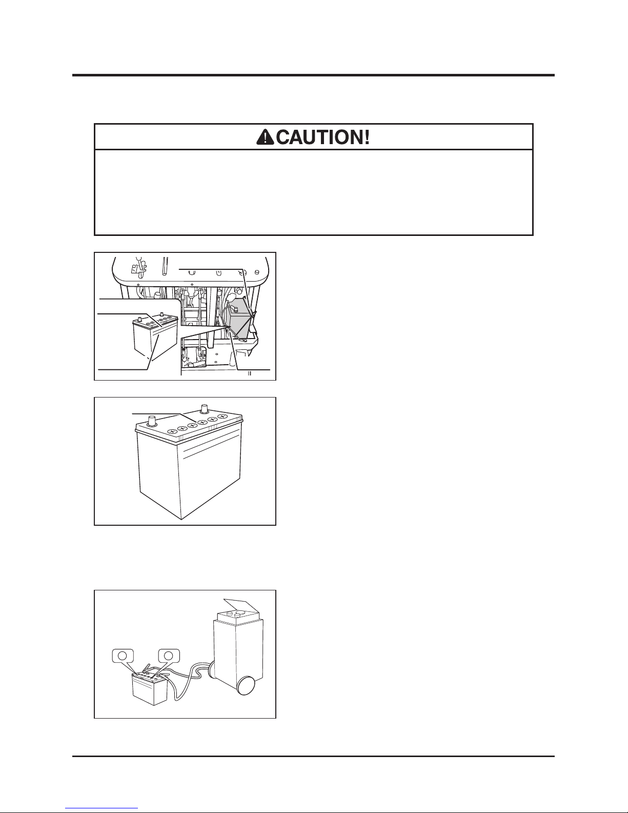
4. Remove the battery bracket and the battery
from the machine.
5. Open the ller plugs and ll distilled water
in the battery evenly until the uid level is
between the "Upper Level" and "Lower
Level" lines.
6. Put the ller plugs back in place.
7. Install the battery.
8. Install the right side and back panels. (Page
35)
UPPER LEVEL
LOWER LEVEL
Filler Plugs
3570M-0509-020E
1. Park the machine on a level ground.
2. Remove the right side and back panels.
(Page 35)
3. Visually inspect that the battery uid level
is between the "Upper Level" and "Lower
Level" lines. If the uid level is below the
"lower Level," ll.
Inspecting
1. Remove the right side and back panels.
(Page 35)
2. Disconnect the (-) cable from the terminal.
3. Disconnect the (+) cable from the terminal.
4. Remove the battery off the machine.
5. Remove all the ller plugs.
6. Follow the instructions in the battery charger
user's manual to charge the battery.
Charging
UPPER
LEVE
L
LOWER
LEVEL
3570M-0507-160E
Battery
Battery Bracket
Upper Limit
Lower Limit
UPPER LEVEL
LOWER LEVEL
-
+
+ -
3570M-0509-030E
• Always remove the battery from the machine before charging. Failure to do so
causes damage to the electrical components and wiring.
• Follow the battery charger user's manual when charging.
Filling
Page 64
-55-
Maintenance 5
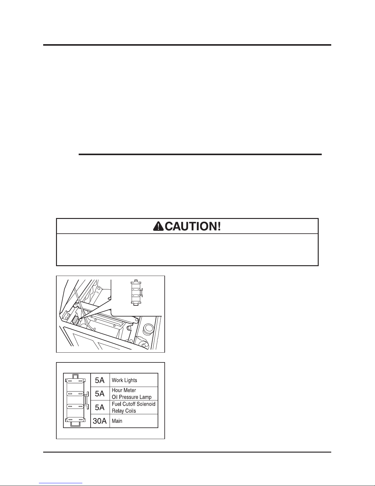
Fuses
1. Open the engine hood and hold it in place
with the engine hood stay.
2. Take the lid off the fuse housing.
3. Locate the blown fuse and replace it with a
new one of the correct rating.
4. Put the lid back in place.
5. Undo the engine hood stay and close the
engine cover.
• If a fuse blows, investigate the cause before replacing. Always replace a fuse
with the one of the correct rating.
3570M-0509-040E
Fuse Housing
7. When the battery is fully charged, put the
ller plugs back in place and install the
battery.
8. Connect the (+) cable from the terminal.
9. Connect the (-) cable from the terminal.
10. Install the right side and back panels. back in
place.
• Consider rapid charging as an emergency measure. This method uses a large
amount of current to compensate the lost charge in a short time. However, the
battery needs to be fully charged in the ordinary method for a longer service life.
NOTE
3570M-0509-050E
Page 65
Maintenance
-56-
5
After Normal Use
1. Clean the machine; take off of dirt, mud, and othe foreign matters after use.
2. If the machine is to be left outside, cover the machine with protective, water-proof
covering after the machine is cooled off.
• Do not wash the engine, control panel, electrical parts, or tank caps with air
breather with running water; water may enter inside and cause rust or damage.
• Clean the machine after use; leaving dirt or foreign objects may cause damage.
• Do not attempt to move the machine when it becomes inoperable due to
freezing.
1. Clean the machine; remove dirt, mud, and othe foreign matters after use.
2. Park the machine on a paved or rm, dry surface.
3. If the machine is to be left outside, cover the machine with protective, water-proof
covering after it is cooled off.
After Use Care
After Cold Weather Use
Page 66
-57-
Maintenance 5
Storage
1. Follow the instruction in Parking (page 22) to park the machine.
2. Clean dirt off of the machine.
3. Change engine oil (page 37).
4. Clean the air cleaner (page 37).
5. Drain the fuel tank.
6. Drain the carburator.
7. Remove the battery from the machine. Service the battery (page 53).
8. Cover the machine with protective, water-proof covering after the machine is cooled off.
• Do not wash the engine or control panel with running water; water may enter
inside and cause rust or damage.
• Clean the machine before storage; leaving dirt or foreign objects may cause
damage.
• Do not store the machine in a humid, dusty, or hot place.
• Fire hazard; do not store the machine where there is a possiblity of ignition.
• Battery dischages even when it is not in use. A battery may hold charge for a few
months, but it is a good practice to charge the battery before it goes at; it will
extend the battery life.
• Refer to the Operation Manual for the engine, for detailed instructions on preparing
the engine for storage.
NOTE
Page 67
Troubleshooting
-58-
6
Troubleshooting
• If any malfunction or abnormal condition is found, immediately stop using the
machine and take an appropriate measure according to the Troubleshooting chart
below. If the malfunction or abnormal condition is not listed in the chart, or the
suggested measure does not solve the problem, consult with your CANYCOM
representative.
• Some corrective measu r e s l i s t ed below require special k n o w l e d g e and/or
equipment. Please contact your CANYCOM representative in such a case.
Area M a l f u n c t i o n P o s s i bl e C a u se Corrective Measure R e f .
E n g i n e
Engine does not start,
or is difcult to start
Parking brake lever
is engaged (in
the position -
safety mechanism is
working).
→Disengage the
parking brake.
Battery is discharged. →Add battery uid.
→Charge the battery.
→Replace the battery.
Page 53
Battery cable is
disconnected.
→Connect the battery
cable.
Blown fuse. →Replace the fuse. Page 55
Bad connection or
breakage in the wiring.
→Please contact
your CANYCOM
representative.
Out of fuel. →Fill fuel. Page 14
Air is in fuel. →Please contact
your CANYCOM
representative.
Engine fouled. →Wait a while and try
starting again.
Insufcient or wrong
oil.
→Fill or change oil. Page 37
Dirty or damaged
spark plug.
→Clean or replace the
spark plug.
Page 40
Contamination in fuel
system.
→Please contact
your CANYCOM
representative.
Other (other than the
above).
→Please contact
your CANYCOM
representative.
Page 68
-59-
Troubleshooting
6
Area
M a l f u n c t i o n
P o s s i bl e C a u se Corrective Measure R e f .
E n g i n e
Engine stalls.
Out of fuel. →Fill fuel. Page 14
Cold engine. →Warm up the engine.
Other (other than the
above).
→Please contact
your CANYCOM
representative.
Engine stops abruptly.
Out of fuel →Fill fuel. Page 14
Piston seizure due to
insufcient or bad oil.
→Please contact
your CANYCOM
representative.
Other (other than the
above).
→Please contact
your CANYCOM
representative.
Engine does not stop
Electrical malfunction →Please contact
your CANYCOM
representative.
Other (other than the
above).
→Please contact
your CANYCOM
representative.
Idling is not stable.
Insufcient intake air
(clogged air cleaner).
→Clean or replace the
air cleaner.
Page 39
Other (other than the
above).
→Please contact
your CANYCOM
representative.
Poor power or
acceleration
Bad fuel →Change fuel.
Wrong oil (improper
viscosity)
→Change to suitable
oil.
Page 37
Accelerator (throttle) is
not properly adjusted.
→Please contact
your CANYCOM
representative.
Insufcient intake air
(clogged air cleaner).
→Clean or replace the
air cleaner.
Page 39
Excessive load →Reduce load.
Loose drive belt. →Adjust Page 46
Other (other than the
above).
→Please contact
your CANYCOM
representative.
Irregular noise or
vibration from or
around the engine
→Please contact
your CANYCOM
representative.
Page 69
Troubleshooting
-60-
6
Area M a l f u n c t i o n P o s s i bl e C a u se Corrective Measure R e f .
Excessive oil
consumption
→Please contact
your CANYCOM
representative.
Engine overheats
Insufcient amount of
engine oil.
→Fill oil. Page 37
Cooling fan is clogged
or blocked.
→Clean.
Other (other than the
above).
→Please contact
your CANYCOM
representative.
Excessive fuel
consumption
Clogged air cleaner. →Clean or replace the
air cleaner.
Page 39
Other (other than the
above).
→Please contact
your CANYCOM
representative.
Black smoke comes
out of exhaust
Bad fuel. →Change fuel.
Clogged air cleaner. →Clean or replace the
air cleaner.
Page 39
Choke is not fully
open.
→Open the choke fully.
Other (other than the
above).
→Please contact
your CANYCOM
representative.
White or blue smoke
comes out of exhaust
Engine oil level is too
high.
→Adjust the oil level.
Other (other than the
above).
→Please contact
your CANYCOM
representative.
D r i v e
T r a i n
Machine does not
move (forward,
backward, turning)
when the control stick
is in the corresponding
position.
Clutch is not engaged →Engage the clutch.
Parking brake is
applied
→Release the parking
brake.
Page 19
Excessive load →Reduce load.
Insufcient or
deteriorated HST uid.
→Add or change uid. Page 42
Other (other than the
above).
→Please contact
your CANYCOM
representative.
Irregular noise or
heat is observed at or
around the track.
→Please contact
your CANYCOM
representative.
Page 70

-61-
Troubleshooting
6
Area
M a l f u n c t i o n
P o s s i bl e C a u se Corrective Measure R e f .
B r a k e
Brake does not work
well.
Not properly adjusted. →Adjust. Page 47
Brake is wet with
water.
→Apply brake a few
times to dry.
Other (other than the
above).
→Please contact
your CANYCOM
representative.
T r a c k
Track does not move
smoothly.
Not properly adjusted. →Adjust. Page 41
Other (other than the
above).
→Please contact
your CANYCOM
representative.
S a f e t y
D e v i c e s
Lamp does not light.
Blown bulb. →Replace.
Blown fuse. →Replace. Page 55
Other (other than the
above).
→Please contact
your CANYCOM
representative.
Horn does not work.
Blown fuse. →Replace. Page 55
Other (other than the
above).
→Please contact
your CANYCOM
representative.
Hyd r a u lic
( D u m p )
s y s t e m
Dump does not work.
Insufcient or
deteriorated hydraulic
uid.
→Add or change uid. Page 42
Loose hydraulics belt. →Adjust. Page 52
Other (other than the
above).
→Please contact
your CANYCOM
representative.
Page 71

Transporting
-62-
7
• Park the transporter (truck) on a level ground. Always use chocks to secure the
wheels.
• Do not allow bystandars to come close to the machine or the transporter when
loading or unloading the machine.
• Use only the loading ramps with sufcient strength (to withstand the combined
weight of the machine and the operator), width (more than 1.2 times the width
of the track), and length (more than 3 times the height of the loading deck of the
transporter), and have anti-slip ramp surfaces.
• Secure the hooks of the loading ramps rmly and ush with the loading deck.
• Never ride the machine when loading to or unloading from the transporter. Fold
the step and drive in the walk-behind mode.
• Move slowly forward when loading onto, and move slowly backward when
unloading off of the transporter. Pay special care when going over the joint
between the loading deck and the ramps; the machine may tip.
• Do not turn on the loading ramps. The machine may fall.
• Tie down the machine securely. Make sure the machine does not move around.
Hauling
Page 72
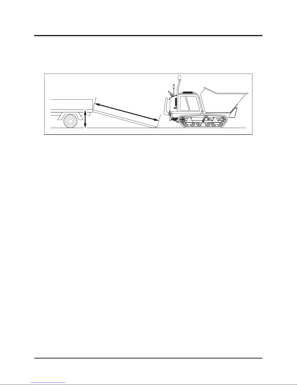
-63-
Transporting
7
3570M-0701-010E
More than 3 thimes
the height
Height
Loading and Unloading
Loading to the Transporter
1. Park the transporter. Secure the wheels with chocks.
2. Place the loading ramps. Secure the hooks of the ramps rmly and ush with the
loading deck.
3. Fold the step. (Page 27)
4. In the walk-behind mode, drive the machine slowly backward onto the loading deck.
5. Park the machine according to the instructions in "Parking" (Page 22).
6. Secure the machine onto the loading deck with rope or tie-down belts.
1. Park the transporter. Secure the wheels with chocks.
2. Undo rope or tie-downs that secure the machine.
3. Place the loading ramps. Secure the hooks of the amps rmly and ush with the loading
deck.
4. In the walk-behind mode, drive the machine slowly forward from the loading deck to the
ground.
Unloading from the Transporter
Page 73
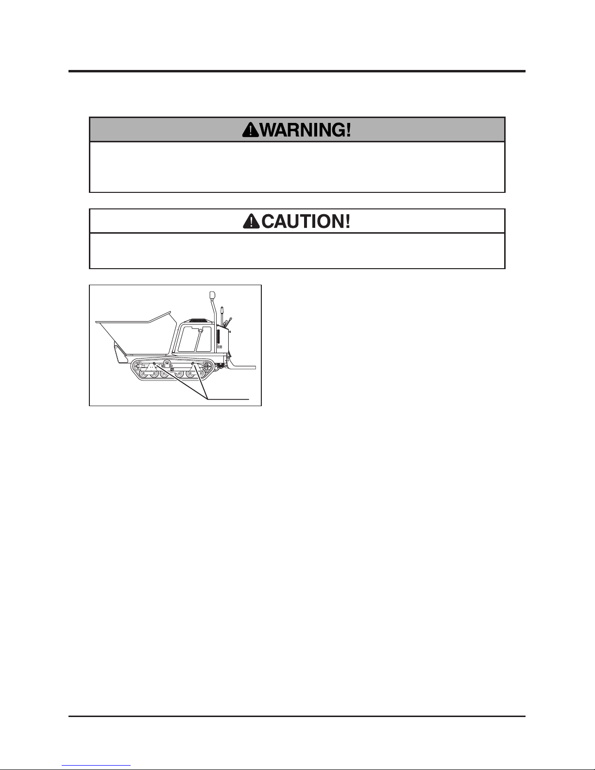
Transporting
-64-
7
• Always unload the machine before hoisting.
Hoisting
1. Attach hoisting wire ropes to the 4 lift hooks
located on the corners of the machine. Hoist
the center of the ropes.
3570M-0701-020E
Lift Hooks
• Use hoisting (slinging) attachments (wire ropes, chains, etc.) of sufcient
strength. Always use the ones of the same length when more than one is used.
 Loading...