


Off-road Rubber Track Dumper
S25A
Operator's Manual
Read this manual completely before operating or maintaining this machine.
Failure to follow safety precautions could result in serious injury or death.
Keep this manual for future reference by you and by all those who operate
and maintain this machine.
Original Instructions
3670 5601 004
(in English)

http://www.canycom.co.jp/
90-1 Fukumasu, Yoshii-machi,
Ukiha-shi, Fukuoka, Japan 839-1396
Sales Headquarters (International) TEL +81-(0)943-75-2195
FAX +81-(0)943-75-4396
Authorized Dealer
All rights reserved. Unauthorized use or reproduction of this material is prohibited.

Notice to Users and Maintenance Personnel
Thank you for purchasing this machine.
This manual provides information needed for safe and effective use of this machine to
those who operate or maintain the machine. Make sure to read and understand the manual
thoroughly before operating this product. Also make sure to read the separate operator's
manual for the engine.
• This machine can be very dangerous if the safety precautions in this manual
and on the l abels attach ed to this m achine are n ot fol lowed. Read and
understand this manual and the safety labels on the machine thoroughly before
using this machine. Always follow the instructions and safety precautions, or
serious injury or death could result.
• This machine should only be used for its intended purpose: hauling and
dumping. Any other use could be dangerous.
• This machine may not be operated on public road or what is considered to
be public road. It is the sole responsibility of the operator to consult the local
regulations.
• Do not modify this machine, or do not operate this machine with the safety
covers removed or open. A serious accident could result.
• Store this manual in a safe, accessible place for easy reference.
Notice to Owner
• Be sure that everyone who uses this machine, including those who rent or
lease this machine, receives a copy of this Operator's Manual and understands
the importance of reading and following the information in this manual.
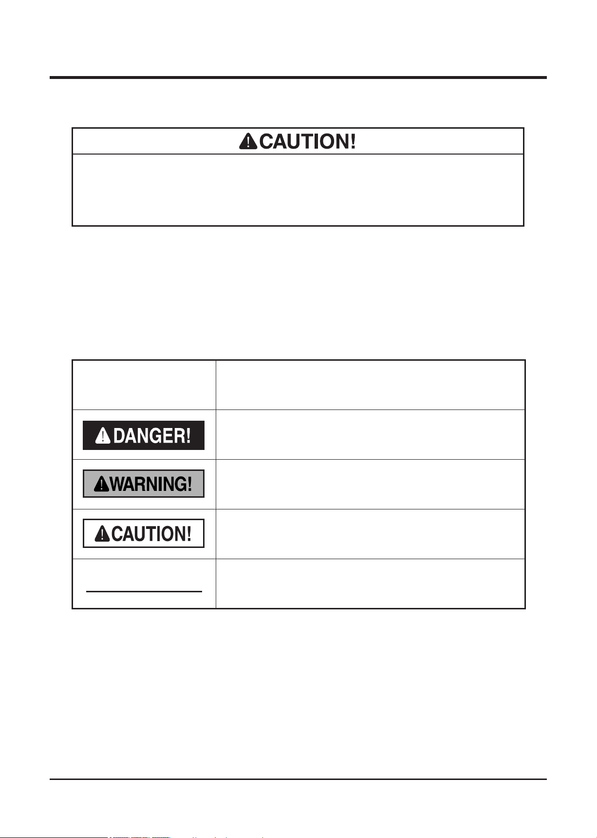
Warning Terms Used in this Manual
In this manual, the following four warning terms are used to signal the four levels of hazard
(or seriousness of possible accidents). Read and understand what they mean and always
follow the instructions in this manual.
Warning Term Definition
Indicates an imminently hazardous situation which will result
NOTE
in death or serious injury if the user does not follow the
procedures or the instructions.
Indicates a potentially hazardous situation which could result
in death or serious injury if the user does not follow the
procedures or the instructions.
Indicates a potentially hazardous situation which could result
in minor to moderate injury or damage to the machine if the
user does not follow the procedures or the instructions.
Indicates important information which needs particular
attention.

Warranty and After-Sales Service
3670M-0005-023E
3670M-0005-013E
Location of Model Label
Warranty
CHIKUSUI CANYCOM, INC. guarantees this product, based on the terms of warranty. A
copy of this warranty is reproduced in the back of this manual.
After-Sales Service
Consult your local CANYCOM dealer or our company’s sales department regarding service
orders or any questions or problems that may arise when using this machine. Please
make sure to have the product name, serial number, and the make and type of the engine
handy at the time of contact. The model and serial number can be found on the model
label as shown below, and the make and type of the engine can be found in Chapter3
"Specifications" of this manual (Page17).
Location of Model Label Model Label
Availability of Spare Parts
The replacement or repair parts for this product shall remain available for seven years after
the production of this type of machine is discontinued.

Contents
1. Safety
Safety Labels . . . . . . . . . . . . . . . . . . . . . . . . . . . . . . . . . . . 1
Safety Precautions. . . . . . . . . . . . . . . . . . . . . . . . . . . . . . . 7
Training . . . . . . . . . . . . . . . . . . . . . . . . . . . . . . . . . . . . . . . . . . . . . . . . . . . . . . . 7
Preparation . . . . . . . . . . . . . . . . . . . . . . . . . . . . . . . . . . . . . . . . . . . . . . . . . . . . 8
Operation. . . . . . . . . . . . . . . . . . . . . . . . . . . . . . . . . . . . . . . . . . . . . . . . . . . . . . 8
Servicing . . . . . . . . . . . . . . . . . . . . . . . . . . . . . . . . . . . . . . . . . . . . . . . . . . . . . 13
1
2. Controls and Components 14
Name and Function of Controls . . . . . . . . . . . . . . . . . . . 14
3. Specifications 17
Product Specifications . . . . . . . . . . . . . . . . . . . . . . . . . . 17
Contents of the Tool Bag . . . . . . . . . . . . . . . . . . . . . . . . 18
4. Operation 19
Preparation . . . . . . . . . . . . . . . . . . . . . . . . . . . . . . . . . . . . 19
Pre-start up Inspection . . . . . . . . . . . . . . . . . . . . . . . . . . . . . . . . . . . . . . . . . 19
Checking and Filling Fuel . . . . . . . . . . . . . . . . . . . . . . . . . . . . . . . . . . . . . . . 19
Adjusting Seat . . . . . . . . . . . . . . . . . . . . . . . . . . . . . . . . . . . . . . . . . . . . . . . . 20
Using Seat Belt . . . . . . . . . . . . . . . . . . . . . . . . . . . . . . . . . . . . . . . . . . . . . . . . 21

Driving. . . . . . . . . . . . . . . . . . . . . . . . . . . . . . . . . . . . . . . . 21
Starting . . . . . . . . . . . . . . . . . . . . . . . . . . . . . . . . . . . . . . . . . . . . . . . . . . . . . . 21
Driving . . . . . . . . . . . . . . . . . . . . . . . . . . . . . . . . . . . . . . . . . . . . . . . . . . . . . . . 24
Stopping . . . . . . . . . . . . . . . . . . . . . . . . . . . . . . . . . . . . . . . . . . . . . . . . . . . . . 28
Stopping with Fuel Cutoff Lever . . . . . . . . . . . . . . . . . . . . . . . . . . . . . . . . . . 28
Parking. . . . . . . . . . . . . . . . . . . . . . . . . . . . . . . . . . . . . . . . . . . . . . . . . . . . . . . 29
Working . . . . . . . . . . . . . . . . . . . . . . . . . . . . . . . . . . . . . . 30
Dumping . . . . . . . . . . . . . . . . . . . . . . . . . . . . . . . . . . . . . . . . . . . . . . . . . . . . . 31
Dumping and Turning Bucket . . . . . . . . . . . . . . . . . . . . . . . . . . . . . . . . . . . . 31
Using Safety Prop . . . . . . . . . . . . . . . . . . . . . . . . . . . . . . . . . . . . . . . . . . . . . 32
5. Maintenance 33
Maintenance Schedule . . . . . . . . . . . . . . . . . . . . . . . . . . 33
List of Fluids and Lubricants . . . . . . . . . . . . . . . . . . . . . 38
List of Consumables and Spares . . . . . . . . . . . . . . . . . . 39
Engine . . . . . . . . . . . . . . . . . . . . . . . . . . . . . . . . . . . . . . . . 42
Engine Oil . . . . . . . . . . . . . . . . . . . . . . . . . . . . . . . . . . . . . . . . . . . . . . . . . . . . 42
Oil Filter . . . . . . . . . . . . . . . . . . . . . . . . . . . . . . . . . . . . . . . . . . . . . . . . . . . . . . 43
Air Cleaner . . . . . . . . . . . . . . . . . . . . . . . . . . . . . . . . . . . . . . . . . . . . . . . . . . . 44
Coolant . . . . . . . . . . . . . . . . . . . . . . . . . . . . . . . . . . . . . . . . . . . . . . . . . . . . . . 45
Fan Belt . . . . . . . . . . . . . . . . . . . . . . . . . . . . . . . . . . . . . . . . . . . . . . . . . . . . . . 47
Fuel System. . . . . . . . . . . . . . . . . . . . . . . . . . . . . . . . . . . . . . . . . . . . . . . . . . . 48
Drive Train. . . . . . . . . . . . . . . . . . . . . . . . . . . . . . . . . . . . . 50
Tracks . . . . . . . . . . . . . . . . . . . . . . . . . . . . . . . . . . . . . . . . . . . . . . . . . . . . . . . 50
HST (Hydrostatic Transmission) Fluid . . . . . . . . . . . . . . . . . . . . . . . . . . . . . 52
Steering Lever. . . . . . . . . . . . . . . . . . . . . . . . . . . . . . . . . . . . . . . . . . . . . . . . . 55
Travel Motor. . . . . . . . . . . . . . . . . . . . . . . . . . . . . . . . . . . . . . . . . . . . . . . . . . . 56
Greasing . . . . . . . . . . . . . . . . . . . . . . . . . . . . . . . . . . . . . . . . . . . . . . . . . . . . . 57

Electrical System . . . . . . . . . . . . . . . . . . . . . . . . . . . . . . . 58
Battery . . . . . . . . . . . . . . . . . . . . . . . . . . . . . . . . . . . . . . . . . . . . . . . . . . . . . . . 58
Fuses . . . . . . . . . . . . . . . . . . . . . . . . . . . . . . . . . . . . . . . . . . . . . . . . . . . . . . . . 61
After Use Care . . . . . . . . . . . . . . . . . . . . . . . . . . . . . . . . . 62
After Normal Use . . . . . . . . . . . . . . . . . . . . . . . . . . . . . . . . . . . . . . . . . . . . . . 62
After Cold Weather Use . . . . . . . . . . . . . . . . . . . . . . . . . . . . . . . . . . . . . . . . . 62
Storage . . . . . . . . . . . . . . . . . . . . . . . . . . . . . . . . . . . . . . . 63
6. Troubleshooting 64
Troubleshooting . . . . . . . . . . . . . . . . . . . . . . . . . . . . . . . . 64
7. Transporting 68
Hauling . . . . . . . . . . . . . . . . . . . . . . . . . . . . . . . . . . . . . . . 68
Loading and Unloading . . . . . . . . . . . . . . . . . . . . . . . . . . . . . . . . . . . . . . . . . 68
Hoisting and Towing . . . . . . . . . . . . . . . . . . . . . . . . . . . . 70
Hoisting . . . . . . . . . . . . . . . . . . . . . . . . . . . . . . . . . . . . . . . . . . . . . . . . . . . . . . 70
Towing . . . . . . . . . . . . . . . . . . . . . . . . . . . . . . . . . . . . . . . . . . . . . . . . . . . . . . . 71

Warranty
Warranty Certificate is attached at the end of this manual.
* Have the warranty certificate signed and sealed after you have received and fully
understood the instructions for handling this machine and received the receipt.
Appendix
• Operator's Manual for the Engine
* Be sure to read and understand it together with this manual .

Safety 1
3670M-0101-013E
(Left and right)
<Both Models>
Safety Labels
The safety labels shown on the next page are attached to the machine. See the illustration
below for the location and the illustration on the next page for the content of each label on
the machine.
• Locate all the warning labels attached to this machine. Read and follow the
instructions and precautions in them. Failure to do so could result in serious injury
or death to the operator or bystanders.
• Keep the labels clean and legible. Do not use solvents or gasoline to clean the
labels.
• Replace these labels immediately if they have been removed, have fallen off or
become illegible. Use the part number, on the label or shown in this manual, to
order a replacement label from your CANYCOM representative.
-1-

Safety
-2-
1
(Back of load-deck)(Back of load-deck)
<One-side-dump>
<Turn & Dump>
3670M-0101-023E
3670M-0101-033E
1
52295124000 36675068000 36675065000
52295119000
2 3 4

Safety 1
-3-
11
8
5 6 7
36675063000
52295116000
52345067000
52295107000
36675064000
36675066000
52295104000
9
10
3670M-0101-043E

Safety
-4-
1
12 13
14
16
52295138000
52295111000
36705114000
52295112000
3670M-0101-053E
ATTENTION
Ne surchargez jamais la benne.
Ne dépassez pas la vitesse limite
décrite sur la graphe ci-dessous
lorsque vous vous déplacez sur
une pente raide
.
Si vous allez trop vite, vous risquez
de ne pas pouvoir freiner la machine
avec le frein.
Si vous decendez une pente avec une
charge, ralentissez si la pente
devient plus raide
.
La plage de sécurité
en charge maximum
est représentée avec
la coloration
Pente
Vitesse de déplacement
0
1 2 3 4 5 6 7 8 9 10
2
4
6
8
10
12
14
16
(Degrés)
17
36705111000

Safety 1
-5-
15
36775063000
3670M-0101-063E
AVERTISSEMENT
Ne faites pas d marrer
le moteur dans un local
clos. Les gaz d' chappement
peuvent provoquer un
empoisonnement gazeux.
La machine doit tre charg e et d charg e
lentement,sur un terrain fe
rme et bien horizontal.
Le v hicule doit tre vide, les op rations se
faire lentement et on doit utiliser des planches
de roulage. Le v hicule doit monter en marche Avant
et descendre en marche Arri re. Le chargement et le
d chargement de la machine doit se faire prudemment,
parce que le centre de gravit peut bouger brusquement.
Si vous changez brusquement la direction alors que
vous tes sur les planches de roulage, cela risque
de faire tomber la machine. Ceci est donc ˆ viter.
Si une charge est pos e sur la
machine avec un quilibre mal
r parti, ceci peut faire ren
verser
la machine. Assurez vous que la
charge est bien r partie
.
Barre de soutien
pour emp cher la
benne de descendre
Levier de
benne
Plaque de
blocage
du levier
Ne laissez pas la machine avec la benne relev e tel quel. En effet,si quelqu' un
venait ˆ toucher au levier de benne par erreur, celle-ci pourrait descendre et
causer un accident.
Lorsque des v rifications sont en cours avec la benne relev e, vous riquez de
vous laisser prendre par la benne. Il faut donc tendre le v rin au maximum
de sa course,arr ter le moteur, puis verrouiller le levier de benne et soutenir
celle-ci fe
rmement au moyen de la tige anti-chute de benne.
Les op rations avec le levier de benne doivent se faire autant que possible
sur des terrains plats et fe
rmes. Sur des zones en pente ou de plan in gal, le
centre de gravit se d place et la machine risque de se ren
verser.
Avant d' actionner le levier de benne, assurez vous qu' il n' y a personne autour.
Ne pas conduire la machine avec la benne relev e. Cesi rend non seulement la
visibilit mauvaise, mais le centre de gravit devient plus haut, ce qui peut
pro
voquer le renversement de la machine.
AVERTISSEMENT AVERTISSEMENT
AVERTISSEMENT
Avant d' actionner le levier de benne, retirez la tige anti-chute qui est sous la
benne. Si la benne est actionn e alors que la tige anti-chute n ' est pas enlev e,
le cadre ainsi que la tige anti-chute risquent d' tre ab”m s.
18
19
36705103000
36705105000
Safety
-6-
1
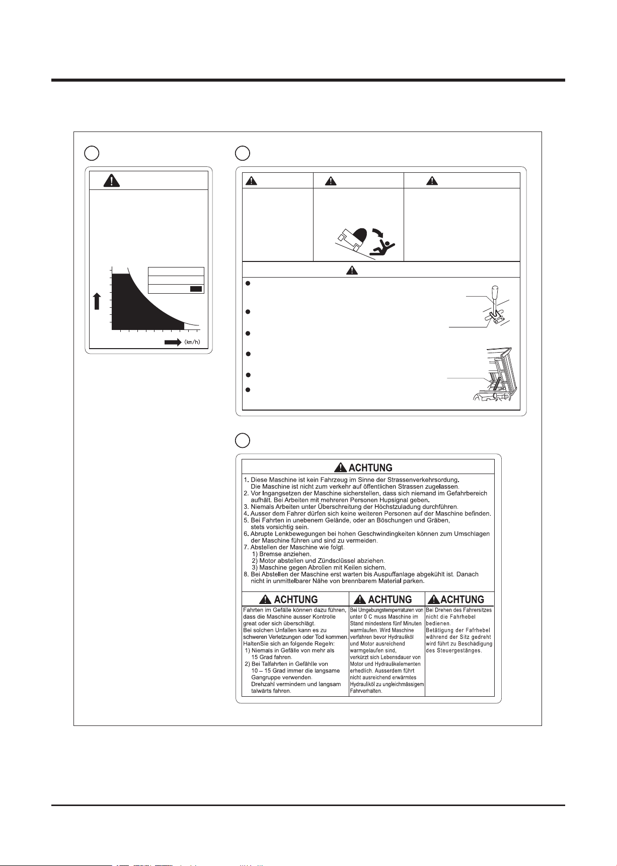
ACHTUNG
Kipper niemals überladen.
Bei Fahrten im Gefälle keinesfalls
die unten angegebene
Höchstgeschwindigkeit überschreiten.
Bei Überschreiten der
Höchstgeschwindigkeit besteht
Gefahr dass Bremsen das Fahrzeug
nicht zum Stehen bringen können.
Bei Gefällefahrten unter Last,
Fahrgeschwindigkeit zurücknehmen
wenn Gefälle zunimmt.
Zulässiger
Arbeitsbereich unter
Höchstzuladung
Gefälle
Fahrgeschwindigkeit
0
1 2 3 4 5 6 7 8 9 10
2
4
6
8
10
12
14
16
(Grad)
Motor nicht in
geschlossenen RŠumen
laufen lassen.
Vergiftungsgefahr durch
Motorabgase.
Be-und Entladen des Kippers nur auf ebenen,
festem Untergrund vornehmen.
Langsam beladen,und eine Rampe verwenden.
Wenn Rampe verwendet wird , auf
Schwerpunktverlagerung achten.
Rasche Ve
rlagerung des Schwerpunktes kann
zum Umschlagen der Maschine fŸhren.
BergwŠrts im
VorwŠrtsgang,
TalwŠrts im RŸckwŠrtsgang fahren.
Kipper nur gleichmŠssig beladen.
Bei einseitiger Beladung besteht
Gefahr dass Maschine sich
ŸberschlŠgt.
Sicherungsblock
Kipphebel
Kulissensicherung
Kippvorgang mšglichst nur auf ebenem, festem Grund durchfŸhren.
Im GefŠlle und auf unebenem Boden besteht Gefahr dass die Maschine
aufgrund der Schwer punktverlagerung umschlŠgt.
Niemals zwischen ungesicherten Kipper und Maschine aufhalten.
MŸssen Wa
rtungen durchgefŸhrt werden erst Hubzylinder bis zum Anschlag
ausfahren, dann Kipphebel mit Kulissensicherung blockieren.
Danach Kipper mit Sicher ungsblock abstŸtzen. Erst danach Wartung durchfŸhren.
Sicherungsblock vor Einfahren des Kippers abrŸsten. Einfahren des
Kippers gegen Sicherungsblock fŸhr t zu BeschŠdigung von
Kipper, Sicherungsblock und Hydraulikzylinder
.
Maschine nicht mit aufgestelltem Kipper fahren. Der erhobene Kipper engt das
Sichtfeld ein, und fŸhrt zu hoher Schwerpunktlage
.
Dies kann zum Umschlagen der Maschine fŸhren.
Vor Einfahren des Kippers sicherstellen dass sich niemand im
Gefahrenbereich des Kippers aufhŠlt.
WARNUNG
Maschine niemals mit erhobenem Kipper abstellen. Andere Personen kšnnten
irrtŸmlich den Kipphebel betŠtigen und zwischen Maschine und einfahrenden
Kipper geraten.
WARNUNG
WARNUNG
WARNUNG
20 21
22
36705112000
36705104000
36705106000
3670M-0101-073E

Safety 1
-7-
Safety Precautions
This section contains safety precautions to follow when operating and maintaining the
machine. Read and understand the precautions in this section as well as throughout this
manual and follow them when operating or maintaining the machine. Failure to follow safety
precautions could result in property damage, serious injury or death to the operator or
bystanders.
Training
All operators and mechanics should receive practical instructions from their employer or
renter. Such instructions should cover the following issues:
• It is essential to familiarize yourself with the controls, safety labels and the proper
use of the machine.
• Never allow people unfamiliar with these instructions to operate or service the
machine. Do not let anyone under 18 years of age to operate this machine. Local
regulations may restrict the minimum age for operating the machine. Consult your
local authority.
• The operator is responsible for the accidents or hazards caused to other people or
their property.
• This machine has a riding capacity for one person only. Do not carry passengers
other than the operator.
• Always keep in mind that care and concentration is required when working with
ride-on machines.
• Loss of control on a slope cannot be regained by the application of the brake. The
main reasons for loss of control are:
→ insufficient grip of tracks.
→ excessive speed.
→ misjudging of the ground conditions, especially slopes.
→ excessive load.
→ incorrect distribution of load.

Safety
-8-
1
Preparation
• Fuel is highly flammable. See Checking and Filling Fuel, page 19, for important
safety information on handling fuel.
• Always wear protective footwear, long trousers, hardhat, safety glasses and ear
protection when operating or servicing the machine. Proper clothing will minimize
the chance of injury. Do not operate the equipment if you have long hair, loose
clothing, or jewelry; all of which may get tangled in moving parts. Do not operate
the machine barefoot or with open sandals.
• Prepare beforehand the working rules and procedures such as signaling and trafic
control for the work place. Following such rules will reduce the risk of accidents.
• Never handle fuel or grease, service the engine, or recharge the battery in the
presence of fire or spark.
• Perform the daily pre-startup inspection (see Preparation, pages 19) before starting
the machine. Repair or replace damaged parts before starting the machine.
Operation
This machine is intended for carrying sand and dirt. Carrying other materials may damage
the machine. Avoid carrying liquid concrete. That will damage the machine.
The stability of the machine is affected by the speed, rate of steering, terrain and the load.
Always pay close attention to these factors or a loss of control or tip over could occur,
resulting in property damage, serious injury or death.
General Driving
• Do not operate the engine in a confined space where dangerous carbon monoxide
fumes can accumulate.
• Do not touch the engine, muffler or exhaust pipe while the engine is running or soon
after it has stopped. These areas will be very hot and can cause burns.

Safety 1
-9-
• Do not operate the machine under the influence of alcohol or drugs. Do not operate
the machine when you are tired, ill, or not feeling well.
• Always check for obstacles before operating on new terrain.
• Before starting the engine and moving the machine, scan around your surroundings
and make sure all persons and other vehicles are a safe distance away from the
machine. Sound the horn to warn bystanders.
• On the machine equipped with the ROPS, always wear the seat belt when in use.
• Always stay seated in the operator's seat when driving the machine. Never operate
the steering lever off of the machine.
• On a slippery surface, travel slowly and exercise caution to reduce the chance of
skidding or sliding out of control. Never operate on ice.
• Always make certain that there is no obstacle or a person behind the machine when
backing up. After confirming that it is safe to back up, move slowly and avoid sharp
turns.
• To reduce the risk of tip over, pay special attention when encountering an obstacle
or a slope, or when braking on a slope or during a turn. See Driving on a Slope on
the next page.
• Never attempt to drive over a large obstacle such as rock or fallen tree.
• Always travel slowly and use extra caution when operating on unfamiliar terrain. Be
alert when traveling on changing terrain.
• Never operate on terrain that you are not comfortable with. Avoid terrain that is so
rough, slippery or loose that you feel like you could tip over.
• Do not operate the machine near the edge of a cliff, an overhang or a slide area.
• Do not make sudden maneuvers. A sudden start, stop, or turn can make the machine
lose control and could cause a tip over. Be especially cautious when traveling on
soft or wet ground.

Safety
-10-
1
• Drive at a safe speed, taking into account the surface gradient, surface conditions
and load.
• Use an observer to help direct the machine when the visibility is poor, terrain is
rugged or hilly, or maneuvering room is limited. The observer should be able to see
the machine and its immediate surroundings, and should give pre-arranged signals
to direct the operator.
Driving on a Slope
• Never use on a slope steeper than 20 degrees.
• Driving on a slope can be dangerous. It can result in a tip over and cause
serious injury or death. Take the following precautions.
• Always follow proper procedures for driving on a slope as described in this manual.
• Driving on a slope in a wrong manner can cause a loss of control or a vehicle tip
over. Check the terrain carefully before attempting to drive on a slope.
• Never drive on a slope that you are not comfortable with. Avoid a slope that is so
rough, slippery, or loose that you feel like you could tip over.
• When driving up a slope, proceed at a steady rate of speed and throttle position.
• Never move the throttle lever or the control lever suddenly.
• If the engine stalls or loses traction during a climb and cannot make it to the top
of the slope, do not try to turn the machine around. Carefully back down slowly,
straight down the slope.
• Drive straight up or down slopes. Avoid turning on a slope.
• When going over the top of a slope, go slow; an obstacle, a sharp drop, or another
vehicle or person could be on the other side of the crest.

Safety 1
-11-
• Avoid driving the machine across a slope.
• Without a load, drive the machine backwards up a slope (operator's seat toward the
top) when climbing, and drive it forward when going down a slope.
• With a load, drive the machine forward up a slope (operator's seat away from the
top) when climbing, and drive it backwards when going down a slope. Be especially
cautious when operating on a slope with a load.
• When driving down a slope, use the steering levers so that the machine travels
down at the minimum speed. Use the engine speed to help keep the machine speed
low.
Loading and Driving with a Load
• The maximum payload for this machine is 24.5kN (2500kg). Do not exceed this
maximum payload under any circumstance.
• Do not operate on a slope steeper than 20 degrees when carrying a load. Do not
carry more than 1250 kg when operating on a slope between 15 and 20 degrees.
• Load cargo in the bucket so the weight is evenly distributed. When carrying a
cargo, strap the cargo to the load deck to prevent the cargo from shifting. Ensure
that cargo does not obstruct the operator's field of view.
• When carrying a load, drive at a reduced speed. Allow a greater distance for
braking.
• Before crossing a bridge or an overpass, make certain that the total combined
weight of the machine, the load and the driver is within the stated weight limit for
the bridge or the overpass. Then, proceed carefully and at a constant speed.

Safety
-12-
1
Dumping/Turning
When turning the bucket and dumping material from the bucket, take the following
precautions.
• Always follow the proper procedures for dumping or turining as described in this
manual.
• Only operate the bucket with the engine running.
• Always stay seated in the operator's seat when dumping or turning the bucket.
Never operate the dump or turn lever off of the machine.
• Perform the dump operation on a flat, level and stable surface whenever possible.
Raising or lowering the load deck on a slope or rough terrain could result in a tip
over.
• Pay special care when dumping with the bucket turned to a side. Be tentative when
raising the bucket which is turned to a side.
• Make certain that all persons are at a safe distance away from the machine when
raising, lowering, or turning the bucket.
• Do not move the machine or leave it unattended with the bucket in the raised
position.
• Engage the bucket safety prop if you must place any part of your body under the
bucket in the raised position.
Parking
• Park the machine on a flat, level and stable surface. Never park on a slope steeper
than 15 degrees. Avoid parking on a slope less than 15 degrees. If parking on
a slope less than 15 degrees is unavoidable, turn the bucket straight, apply the
parking brake and block the tracks at the lower end of the machine.
→ Without a load, park the machine with the operator's seat facing downhill
→ With a load, park the machine with the operator's seat facing uphill
→ Do not park sideways on a slope.
• Observe all the previous precautions for driving, driving on a slope, loading and
driving with a load, and dumping.

Safety 1
-13-
• Whenever you park the machine, apply the parking brake and stop the engine.
Rem ov e the k ey wh en ev er yo u le ave t he ma ch in e u na tt en d ed t o pre ve nt
unauthorized use or accidental starting.
• Diesel fuel is flammable and can be explosive. When parking the machine indoors,
make certain that the building is well ventilated and that the machine is not close to
any source of flame or spark, including appliances with pilot lights.
Servicing
• Do not service the machine when the engine is running. If it is absolutely necessary
to run the engine while servicing, pay attention to the moving parts; keep hands,
feet, clothing and any part of the body away from any moving part, especially the
cooling fan and the belts at the side of the engine.
• Do not operate the engine in a confined space where dangerous carbon monoxide
fumes can accumulate.
• Make sure all hydraulic line connectors are tight and all hydraulic hoses and lines
are in good condition and leak-free before applying hydraulic pressure to the
system.
• Keep your body and hands away from pinhole leaks or nozzles that eject hydraulic
fluid under high pressure. Use paper or cardboard, not your hands, to search
for leaks. Hydraulic fluid escaping under pressure can have sufficient force to
penetrate the skin and cause serious injury.
• Check all fuel lines on a regular basis for tightness and wear. Tighten or repair them
as needed.
• Do not touch the engine, muffler, or exhaust pipe while the engine is running or
soon after it has stopped. These areas will be very hot and can cause burns.
• The engine must be shut off before checking or adding oil.

Controls and Components
-14-
2
Head Lamp
Roller Bracket
Track
Sprocket
Roller
Upper Roller
Idler
Tailgate
Seat
Parking Brake Lamp
Hour Meter
Horn Button
Lock Plate
Lamp Switch
Dump Lever
Turn Lever
(Turn and Dump Model)
Oil Puressure Lamp
Coolant
Temperature Lamp
Parking Brake Switch
Steering Lever
Accelerator Lever
Ignition Switch
H/L Speed Selecter Switch
Fuel Gauge
Charge Lamp
3670M-0201-013E
Name and Function of Controls

-15-
Controls and Components 2
Accelerator Lever
Steering Lever
Dump Lever
Lock Plate
H/L Speed Selecter Switch
Parking Brake Switch
Lamp Switch
. . . . . . . . . . . . . . . This is used to raise or lower the dump body.
. . . . . . . . . . . . . . . . This is used to lock the dump lever.
. . . . . . . . . . This increases or decreases the engine speed.
. . . . . . . . . . . . T hi s is us ed when turnin g the m ac hine an d when
. . . . . . . This is used when parking the machine. (When the
. . . . . . . . . . . . . . Pressing this button lights up the head lamps.
changi n g t h e d i r ec t i o n o r tr a v e l ( F O R WARD o r
REVERSE).
. . . This is used to switch the travel speed between [HI] and
[LO].
parking brake switch is at the [P] position, the machine
does not move even when the steering lever is operated.)
Horn Button
Turn Lever
Dump Lever
Ignition Switch
Coolant Temperature Lamp
. . . . . . . . . . . . . . . Pressing this switch sounds the horn.
. . . . . . . . . . . . . . . . This lever is used when turning the load deck body (turn
. . . . . . . . . . . . . . . This lever is used when dumping the load deck body.
. . . . . . . . . . . . . This also acts as the main switch. When the key is turned
and dump model).
to the [ ] position, electric current passes through the
electrical circuits of the machine. If the key is turned
further to the [ ] position, the starting motor is cranked. If
the key is turned to the [ ] position, electricity flows to the
glow lamp.
. . This lights up when the engine cooling water temperature
rises abnormally (overheats).

2
Controls and Components
Oil Pressure Lamp
Parking Brake Lamp
Charge Lamp
Fuel Gauge
Hour Meter
. . . . . . . . . . . . . . . . This shows the remaining amount of fuel.
. . . . . . . . . . . . . . . . This displays the total number of hours that the machine
. . . . . . . . . . This shows if the engine oil pressure is normal. When the
. . . . . . . . . . . . . . This displays the condition of the battery charge. When
engine starting switch is turned to the [ ] position,it lights
up, and if the conditions are normal it will go out after the
engine starts.
. . . . . . . . This lights up when the parking brake switch is at the [P
(parking)] position.
the engine starting switch is turned to the [ ] position, it
lights up, and if the condition is normal, it will go out after
the engine starts.
has been working in units of 0.1 hour.
-16-

Specifications 3
Product Specifications
· Use this product properly after understanding its specifications thoroughly.
Model and Type
S25A
One-Side-Dump Turn & Dump
Machine Mass kg 2230 2430
Maximum Payload kN(kgf) 24.5(2500)
Overall Length mm 3295 3665
Overall Width mm 1775 1775
Overall Height mm 2370
Track Contact Length mm 1960
Track Tread mm 1230
Dimensions
Ground Clearance mm 295
Loading Deck Height mm 770 910
Inside
Dimensions
Loading Deck
Payload
Model Kubota V2203
Type 4-cycle, Water-cooled Diesel, in-line 4 cylinder
Length mm 1685 2155
Width mm 1420 1300
Height mm 370 495
Struck m
Heaped m
3
3
0.89 1.03
1.26 1.40
Cylinder (Bore×Stroke) mm 87 X 92.4
Displacement cm
Rated Output kw(PS) 34.1 (46.4)
Maximum Torque
Starter System Electric
Fuel Diesel Fuel
Engine
Fuel Consumption
Fuel Tank Capacity L 45
Oil Capacity L 9.7
Coolant Capacity L 7.2
Battery Type 100E41R
Battery Capacity V/AH 12/80
N•m(kgf•m)/rpm
g/kW•h(g/PS•h)
3
139.6/1600 to 1800 (14.2/1600 to 1800)(7.2)
251 (185)
-17-
2197

3
Specifications
Model and Type
S25A
One-side-Dump Turn & Dump
Travel
Speed
Minimum Turning Radius m 2.0
Gradability Degrees 30 (unloaded)
Performance and
Operating Range
HST Oil Capacity L 36
Main Transmission HST (2-Speed Motor)
Steering System 2-Pump/2-Motor System
Brakes Hydraulic
Drive Train
Dump System Hydraulic Dump
Load Deck Type One-side-Dump Turn & Dump
Hydraulic
Pump
Relief Pressure MPa(kgf/cm2) 15.7 (160) 11.8 (120)
Cylinder(Bore X Stroke) mm 80 X 407
Dumping System
Performance
High Speed km/h 0 to 11
Low Speed km/h 0 to 6
Type Gear Pump
Max. Speed
Max. Discharge
Max. Angle Degrees 60 85
Lifting Time Sec approx. 4.0 approx. 7.4
rpm 2,800
L/min 31
Lowering Time
Hydraulic Fluid Capacity L Shared with HST System
Swivel System - Hydraulic (Twin cylinder)
Swiveling Angle Degrees - 90(Right) - 90 (Left)
Swiveling Time Sec - approx. 6.0
Cylinder(Bore X Stroke) mm - 60 X 250
Swivel System
*These specifications are subject to change without notice.
Sec approx. 3.0 approx. 5.3
Contents of the Tool Bag
No. Content Quantitiy Note
1 Operator's Manual 1 This Manual
2
Operator's Manual for the Engine
1
-18-

Preparation
3670M-0401-010E
Main Switch
Fuel Gauge
3670M-0401-020E
Engine Hood
Handle
Pre-start up Inspection
Always perform an inspection before use.
Operation 4
Refer to
Maintenance Schedule
(page 33) for the inspection schedule and procedure.
Checking and Filling Fuel
• Keep fire and spark away when handling fuel.
• Always stop the engine before refueling.
• Do not overfill fuel so that fuel will not overflow. Check fuel gauge when filling.
In case fuel is spilt, wipe out immediately.
Checking Fuel
1. Insert key into main switch.
2. Turn main switch to [ | (on)] position and
wait a few seconds.
3. Check fuel gauge.
4. Turn main switch to [ (off)] position and
remove key.
Filling Fuel
1. Open engine hood.
-19-

Operation
-20-
4
3670M-0401-040E
Lock Lever
Slide Lever
Seat Back Adjuster
Firmness Adjuster
3670M-0401-050E
3670M-0401-030E
Fuel Filler Cap
2. Open fuel filler cap.
3. Insert key in main switch and turn it to
[ | (On)] position.
4. Fill fuel. Check fuel gauge when filling.
5. Turn main switch to [ (Off)] position and
remove key.
6. Put fuel filler cap back and tighten it securely.
7. Close engine hood.
NOTE
• Fuel : Diesel Fuel.
• Fuel Tank Capacity : 45L
Adjusting Seat
• When adjusting seat, make certain the seat is securely locked.
Turning seat
1. Pull up lock lever to turn seat.
NOTE
• When seat is turned, the direction that seat
is facing is FORWARD for the operation of
steering levers.
Adjusting seat
1. Pull slide lever to slide seat to a desired
position.
2. Pull seat back adjuster to adjust seat back to
the desired position.
3. Pull firmness adjuster lever to adjust the
seat firmness to suit operator's weight and
preference. Pull firmness adjuster lever fuilly
to undo it.

-21-
Operation 4
Seat Belt
3670M-0401-060E
Using Seat Belt
• On machine equipped with ROPS, Always wear seat belt.
1. Buckle up seat belt. Adjust seat belt so that it
fits snugly over the pelvis.
Driving
Starting
• Always start and run the engine in a well ventilated place.
• Always make certain of the safety of your surroundings when starting the
engine.
• An engine that has been running is very hot. Avoid touching the engine and its
ancillaries, or severe burns may result.
• Do not open engine hood while engine is running.

Operation
-22-
4
3670M-0402-010E
Parking Brake Switch
• Do not turn the starter when the engine is running. Starter motor and/or the
engine may be damaged.
• Do not turn the starter for more than 15 seconds. If the engine does not start,
wait for 30 seconds or more before attempting to start again.
• Do not use this machine in temperatures above 40ºC or below -15ºC. This
machine cannot perform adequately in these temperature ranges. Using this
machine under such conditions may result in an accident or cause damage to
the machine.
• In the winter or cold climate, warm up the engine thoroughly before driving
the machine. A cold engine delivers poor performance, which may result in an
accident. It also causes excessive wear.
• Do not use this product in dusty places such as desert. Dust may clog the air
cleaner or enter the engine, which may reslt in loss of performance and an
accident. It also causes excessive wear.
• Do not use this machine in the altitude above 1500m in its original configuration.
This machine cannot perform adequately above that altitude. Using this
machine under such conditions may result in an accident or cause damage to
the machine. If you need to use this machine above that altitude, contact your
CANYCOM representative.
1. Make sure parking brake switch is in [
(parking)] position.

-23-
Operation 4
3670M-0402-020E
Dump Lever
Lock Plate
3670M-0402-030E
Steering Levers
3670M-0402-040E
Main Switch
OFF
Preheat
3670M-0402-050E
Main Switch
OFF
ON
Start
2. Make sure dump and turn (Turn & Dump
model) levers are in the neutral position and
lock plate is in the locked position (around
the base of the levers).
3. Make sure steering levers are in the neutral
position.
4. Insert key into main switch.
5. Turn main switch to [ (preheat)] position.
NOTE
• Preheat engine for about 10 seconds when
star ting in n orma l te mper atur e and for
about 20 to 30 seconds when starting in
cold weather (ambient temperature below -5
°C).
• There is no need to preheat if the engine is
already warm.
7. Turn main switch to [ (start)] position to
start the engine. Once the engine starts,
rel e a s e k e y i m m e d i a t e l y ; s w i t c h w i l l
automatically return to [ | (on)] position.

Operation
-24-
4
3670M-0402-060E
Parking Brake Lamp
Coolant Temperature Lamp
Oil Pressure Lamp
Charge Lamp
8. Move throttle lever to [ (slow)] position.
9. Make certain the warning lamps are not lit.
10. Allow the engine to warm up by running
it for 3-5 minutes without any load. (It is
not necessary when the engine is already
warm.)
NOTE
• Drive the machine gently in the first 40 to 50
hours of use after purchase for breaking-in.
• I f an y of wa rnin g la mps is lit, sto p th e
engine immediately a n d investigate the
cause.
Driving
• Do not allow bystanders to come near the machine when driving.
• Always make certain of the safety of your surroundings before driving; start
slow.
• Always stay seated in the operator's seat when driving the machine. Never
operate the steering lever off of the machine. This may cause the machine to
run over or crush the operator.
• Always make certain of the safety of your surroundings before turning
• Do not make sudden starts, acceralation, change of speed, change of direction,
or stop. Do not turn at speed. Avoid sudden maneuvers; this may cause the
operator to fall or to be thrown, or the machine to tip over.
• Do not turn the key to [ (off)] position while traveling. Machine can lose
stability and tip over.

-25-
Operation 4
3670M-0402-070E
H/L Speed Selecter Switch
Parking Brake Switch
3670M-0402-080E
Steering Levers
• Always move the steering levers back to the neutral position before releasing.
Letting it go from other operating positions may result in sudden deceleration
and can cause the machine to tip over or the operator to fall or to be thrown.
• Do not operate steering levers when the parking brake is engaged (parking
brake pedal is pressed down). It can wear out the brake.
1. M a ke ce r ta i n o f t he sa f et y o f y o ur
surroundings.
2. Turn parking brake switch to [TRAVEL]
position.
3. Push H/L speed selecter switch to either
[ (LO)] or [ (HI)] position. For the
speed range in either position, see "Product
Specification (page 17-18)."
3. Move the throttle lev e r t o w a r d [
(fast)] position or depress throttle pedal to
increase the engine speed.
Moving Forward
4. Move left and right steering levers gradually
for ward together to move the ma chine
forward. The angle of steering levers controls
the machine speed.
NOTE
• When seat is turned, the direction that seat
is facing is FORWARD for the operation of
steering levers.

Operation
-26-
4
3670M-0402-090E
Steering Levers
3670M-0402-120E
Steering Lever (Right)
3670M-0402-110E
Steering Lever (Left)
3670M-0402-100E
H/L Speed Selecter Switch
Moving Backward
5. Move both steering levers gradually
backward together to move the machine
backward. The angle of steering levers
controls the machine speed.
Selecting Speed
6. Push H/L speed selecter switch to either
[ (LO)] or [ (HI)] position. This can
be done while machine is in travel.
Turning Forward
7. Move left steering lever gradually forward to
turn right.
8. Move right steering lever gradually forward
to turn left.

-27-
Operation 4
3670M-0402-130E
Steering Lever (Left)
3670M-0402-140E
Steering Lever (Right)
3670M-0402-150E
Steering Levers
Turning Backward
9. Move left steering lever gradually backward
to turn right backwards.
10. Move right steering lever gradually backward
to turn left backwards.
Pivot Turning
11. Move steering levers in opposite directions
to make a turn on spot (pivot turn).

Operation
-28-
4
3670M-0402-160E
Steering Levers
Neutral
3670M-0402-200E
Fuel Cutoff Lever
Stopping
• Do not make a sudden stop. The machine may skid or tip over.
• Do not release steering levers suddenly. The machine may stop suddenly and
skid or tip over.
• Always park on a firm, level place. Never park on a potentially dangerous place.
1. Move steering levers gradually to the neutral
position to stop machine.
Stopping with Fuel Cutoff Lever
• Do not open engine hood while engine iw running. If it is absolutely necessary
to open engine hood while engine is still running, keep away from moving or
hot parts.
1. Open engine hood.
2. Move fuel cutoff lever to stop engine.

-29-
Operation 4
3670M-0402-170E
Throttle Lever
3670M-0402-180E
Parking Brake Switch
3670M-0402-160E
Steering Levers
Neutral
Parking
• Always park on a firm, level place. Never park on a potentially dangerous place.
• Avoid parking on a slope. Never park on a slope with an incline of 15 degrees or
steeper. If it is absolutely necessary to park the machine on a slope less than
15 degrees, make certain to apply parking brake firmly and block the tracks
with chocks.
1. Move steering levers gradually to the neutral
position to stop machine.
2. Move throttle lever toward [ (slow)]
position to decrease the engine speed.
3. Turn parking brake switch to [P (parking)]
position.

Operation
-30-
4
3670M-0402-190E
Main Switch
OFF
ON
Working
4. Turn main switch to [ (off)] position.
Remove the key from main switch.
NOTE
• Le a vi n g t he ma i n s w it c h i n [ | ( o n ) ]
position drains the battery and cause it to
discharge.
• Always make certain of the safety of your surroundings when dumping or
turning bucket.
• Never operate the dumping or turning lever off of the machine. This may cause
the bucket to hit or cruch the operator or bystander.
• Avoid dumping or turning bucket on a slope. The machine may tip over.
• Always run the engine when dumping or turning bucket.
• When lowering the loaded bucket, slow the engine speed and lower the bucket
gently.

-31-
Operation 4
Dumping
3670M-0403-010E
Throttle Lever
3670M-0403-020E
Dump Lever
Lock Plate
UPDOWN
3670M-0403-030E
Dump Lever
Left Turn
Right Turn
Lock Plate
Turn Lever
1. Move the throttle lever to [ (fast)] position
to increase the engine speed.
2. Turn the lock plate to the side so that the
dump lever can be operated.
Dumping and Turning Bucket
3. M o ve d u m p l e v er gr a du a ll y t o wa r d
[ (up)] to raise bucket.
4. When bucket reaches its upper limit, a
hissing noise is heard; move dump lever
back to [ (neutral)] position.
5. M o ve d u m p l e v er gr a du a ll y t o wa r d
[ (down)] to lower bucket.
6. When bucket r eaches its lower limit, a
hissing noise is heard; move dump lever
back to [ (neutral)] position.
7. Turn lock plate back in place to lock dump
lever.
8. Turn lock plate to the side so that turn lever
can be operated.
9. M o ve t u r n l ev e r g ra du a l l y t o w a r d
[ (left)] to turn bucket left.
10. When bucket reaches its limit, a hissing
noise is heard; move turn lever back to
[ (neutral)] position.
11. M o v e tu r n l e v er g r a du a ll y t o wa rd
[ (right)] to turn bucket right.

4
3670M-0403-050E
Safety Prop
3670M-0403-040E
Clockwise Turn
Counterclockwise Turn
Using Safety Prop
Operation
12. When bucket reaches its limit, a hissing
noise is heard; move turn lever back to
[ (neutral)] position.
13. Turn lock plate back in place to lock turn
lever.
• Place safety prop under bucket when inspecting or working under bucket.
• Make certain to undo safety prop before lowering bucket.
1. Raise bucket.
2. Hold the bucket with safety prop.
-32-

Maintenance 5
Maintenance Schedule
• Follow the scheduled maintenance as described below. Failure to do so may
result in mechanical or property damage, injury or death.
• Perform a pre-startup inspection (PSI) before each use, a monthly inspection once a
month, and a yearly inspection once a year.
• Some maintenance procedures described below may require special knowledge
or tools and instruments. Contact your CANYCOM representative to perform such
procedures.
Item Description
Engine shall start easily without making any
irregular noise.
Glow plugs work correctly.
Engine speed shall be set properly at idle
and at full without loading. Engine shall stay
running smoothly.
When accelerating engine, throttle lever shall
move smoothly, and engine shall accelerate
smoothly without stopping or knocking.
Warm up engine thoroughly, and observe
exhaust sound and gas from idle to fast
speed; exhaust sound shall be normal and
smoke shall not be excessive.
There shall be no leak in exhaust system or
muffler.
Air cleaner case shall not be deformed or
cracked. Case lid and connecting air hose
shall be firmly in place.
Cleaner element shall be in good shape
without damage or excessive dust.
Bolts and nuts fastening cylinder head,
intake and exhaust manifolds shall be tightly
fastened.
* this may be skipped if there is no gas or
water leaks found in these areas.
Engine
General
Starting
Running
Exhaust
Air
Cleaner
Fasteners
Schedule
PSI
Mon
√ √ √
√ √ √
√ √
√ √ √
√ √ √
√ √
√ √
√ √
√
Note
Year
Contact your CANYCOM
representative for
inspection.
Cleaning/Replacing:
Page 44
-33-

Maintenance
-34-
5
Item Description
Valve clearance shall be correct.
Valve
Clearance
Compression
General
Engine
Mount
Lubrication
System
Engine
Fuel System
Cooling
System
* this may be skipped if there is no noise due
to incorrect valve clearance, and engine
runs normally.
Compression shall be normal
* this may be skipped if running and exhaust
conditi on is n ormal at idle and under
acceleration.
Engine base shal l be fre e of cra cks or
deformation.
Mounting bolts and nuts shall not be loose or
missing.
Oil shall be clean and at correct level.
No noticable oil leaks shall be found in head
cover, oil pan, or pipes.
There shall not be any leaks in fuel tank,
hoses, or pipes.
Fuel hos es s hall be fre e of da mage or
deterioration.
Fuel filter shall not be excessively dirty or
clogged.
There shall not be sediment or water in fuel
tank.
Injection puressure and injection condition
from the nozzle shall be normal.
* this may be skipped if running and exhaust
co nd it io n is no rm al a t i dl e an d und er
acceleration.
Coolant shall be clean and at the correct
level.
There shall not be any leaks from radiator,
engine, water pump, or hoses.
Radiator fins shall be free of clogging.
Radiator cap valve shall function properly.
Fan belt shall be free of wear and damage,
and shall be properly tensioned.
Cooling fan, duct, and cover shall be free of
cracks, damage, or deformation.
Mounting bolts and nuts on cooling fan, duct,
and covers shall not be loose or missing.
Schedule
PSI
Mon
√
√
√ √ √
√ √ √
√ √ √
√ √ √
√ √ √
√ √ √
√ √
√ √
√
√ √ √
√ √ √
√ √ √
√
√
√
√
Note
Year
Contact your CANYCOM
representative for
inspection.
Contact your CANYCOM
representative for
inspection.
Inspecting/Changing:
Page 42
Inspecting: Page 49
Inspecting/Removing
water: Page 49
Contact your CANYCOM
representative for
inspection.
Inspecting/Filling:
Page 45
Adjusting: Page 47

-35-
Maintenance 5
Item Description
Charge
System
Battery
Engine
Electrical System
Wiring
HST Pump
Drive Train
Linkage
Wheels
Sprockets
Idlers
Undercarriage
Tracks
Charge system is working correctly.
Battery electrolyte level shall be correct.
Terminals shall be free of marked corrosion
and are tightly secured.
Connections shall be securely connected.
Wiring shall be free of damages.
Drive the machine forward and backward,
turn left and right in both directions; machine
shall move normally and free of irregular
noise or overheating.
Hydraulic fluid shall be filled to a proper
level.
Hydraulic fluid shall be clean and free of dirt
or contamination.
There shall be no fluid leaks in or around
fluid tank.
Rods, links, and wires in linkage shall be free
of deformation or damage.
Connections shall be free of looseness,
excessive play, or missing cotter pins.
Shall be free of cracks, defromation, or
excessive wear.
There shall not be excessive play in axle.
Irregular noise or overheating shall not be
observed when traveling.
Mounting bolt or nut shall not be loose or
missing.
There shall be no oil leak in or around axle.
There shall not be marked cut, deterioration,
or wear.
Track shall be properly tensioned; shall not
be too loose or too tight.
Track core shall not be missing or damaged.
Tension bolt shall be free of deformation or
corrosion.
Schedule
PSI
Mon
√
√ √
√ √
√ √
√ √
√ √ √
√ √
√ √
√ √
√ √
√ √
√ √ √
√ √ √
√ √ √
√ √
√ √ √
√ √ √
√ √ √
√ √ √
Note
Year
Contact your CANYCOM
representative for
inspection.
Inspecting/Filling:
Page 58
Inspecting/Changing:
Page 52
Inspecting/Changing:
Page 52
Adjusting: Page 50

Maintenance
-36-
5
Parking Brake
Linkage
Brake System
Hydraulic
Pump
Hydraulic System
Hydraulic
Valve
Plumbing
Hydraulic System
Hydraulic
Cylinders
Item Description
Parking brake shall work properly.
Parking b rake sha ll be able to hol d the
machine on a 20-degree slope.
Rods, links, and wires in linkage shall be free
of deformation or damage.
Connections shall be free of looseness,
excessive play, or missing cotter pins.
There shall be no leak in or around hydraulic
pump.
Fastening bolts and nuts shall not be loose
or missing.
No irregular vibration, noise, or heat shall
be observed when hydraulic pump is in
operation.
Amount and pressure of discharge under
load shall be within the s tandard range
specified by the manufacturer.
*this may be skipped if irregular vibration,
noi se , or he at d escri be d above i s not
observed.
There shall be no leak in or around hydraulic
valve.
Plumbing shall be free of cracks, damage,
twists, or deterioration.
There shall be no leaks in pipes, hoses,
joints, or seals.
Plumbing shall be mounted properly, and
fastening bolts and nuts shall not be loose or
missing.
Breather shall not be clogged.
Shall work smoothly.
There shall be no leaks when extending and
contracting cylinder.
Exte nd dum p c ylinder fu lly un der loa d
and hold. Stroke shall be within the range
specified by manufacturer.
Cylinder tube and rod shall be free of dents,
cracks, bends, or scratches.
Cylinder mounting pins shall be free of
damage or excessive wear.
Schedule
PSI
Mon
√ √ √
√ √
√ √
√ √
√ √
√ √
√ √
√
√ √
√ √
√ √
√ √
√ √
√ √
√ √
√
√ √
√ √
Note
Year

-37-
Maintenance 5
Item Description
Shall be free of cracks, deformation, or
Chassis
Frame
Body Panels
Loading Deck
Body, Chassis, Loading Deck
Safety Prop
Labels
Work Lamp
Safety Devices
Horn
corrosion.
Fastening bolts or nuts shall not be loose or
missing.
Shall be free of cracks or deformation.
Doors shall open, close, and lock properly.
Fastening bolts or nuts shall not be loose or
missing.
Loading deck shall be raised,lowered and
turned smoothly.
Shall be free of cracks, deformation, or
corrosion.
Fastening bolts or nuts shall not be loose or
missing.
Safety prop shall be free of any deformation.
Warning labels and instruction plates shall
be clean, legible, and free of damage.
Work lamp shall work.
Lamp lens shall be free of cracks or chipping
and water shall not be in the lamp.
Horn shall work.
Schedule
PSI
Mon
√ √
√ √
√ √
√ √ √
√ √
√ √
√ √
√ √
√ √
√ √ √
√ √ √
√ √
√ √ √
Note
Year

Maintenance
-38-
5
List of Fluids and Lubricants
Item Schedule Grade Cap.
Fuel As needed. Diesel Fuel
Engine Oil
HST Fluid Change
Travel Motor Oil Change
C y li nd e r Pi n ,
Ro lle r S u pp o rt
Shaft
Engine Coolant
Battery Electrolyte
Fill
Inspect daily. Fill as needed.
Change
Init i a l l y - A f t e r 5 0 h o u r s o f u s e .
Every 200 hours afterwards.
Initially - After 500 hours.
Every 1000 hours afterwards.
Initially - After 200 hours.
Every 1000 hours afterwards.
Every 1000 hours.
Check Everyday
Add as needed
Change every 2 years
Inspect daily. Distilled Water
Diesel Engine Oil
API rating: CD or better.
SAE rating: 10W-30
High viscosity index hydraulic fluid,
ISO VG46
Engine Oil
API rating: CD or better.
SAE rating: 10W-30
*When using in cold areas
(below -15°C), use wear resistant
hydraulic fluid VG32
Gear Oil
API rating: GL-4
SAE rating: 90
Lithium all-round grease (NGL
No.2 or equivalent)
Long Life Coolant (LLC) and pure
water Mixture
45L
9.7L
or
36L
0.6L
-
7.2L
-

-39-
Maintenance 5
List of Consumables and Spares
• When replacing consumable or spare, always use CANYCOM genuine part.
Item Part No. Schedule Qty.
Engine
Air Cleaner Element (Outer)
Air Cleaner Element (Inner)
Oil Filter
Fuel Filter
Push-Pull Wire (Engine Control)
Wire
Drive Train
Track
Sprocket 15T
Track Roller A Assembly
Track Roller B Assembly
Carrier Roller Assembly
Idler Assembly
Electrical System
Battery (100E41R)
Hydraulic System
R1401-4227-0
R2401-4228-0
3661 0001 300
3664 0221 500
3707 3321 000
3655 0105 100
3663 2111 999
3663 2106 0X0
5232 2201 000
5232 2211 000
3640 2218 0X0
3640 2331 0X0
3661 0502 000
Replace every 1000 hours or if
defective.
Replace every 1000 hours or if
defective.
Initially: 50 hours.
Every 200 hours afterwards.
Replace every 450 hours or if
defective.
Replace if defective. 1
Replace if defective. 1
Replace if defective
or reaches the wear limit.
Replace if defective. 2
Replace if defective. 8
Replace if defective. 4
Replace if defective. 2
Replace if defective. 2
Replace if defective. 1
1
1
1
2
Contact your
Hydraulic Hoses (Dump, Turn,
Oil Cooler, HST)
Suction Filter
Line Filter
CANYCOM
representative for
parts information.
3663 6029 000
3661 6036 300
NOTE
• Track wear limit: 5mm of lug height
Every 2 years
or if defective.
Every 1000 hours. 1
Every 500 hours. 1
1

Maintenance
-40-
5
Item
Hydraulic Hoses
HST Pump Front Right A1 to
HST Motor Top Left P1
HST Pump Front Left B1 to
HST Motor Bottom Left P2
HST Pump Front Left B2 to
HST Motor Bottom Right P2
HST Pump Front Right A2 to
HST Motor Top Right P1
HST Motor Left Drain Bottom T1
to Oil Tank
HST Motor Right Drain Bottom T1
to Oil Tank
Pump Top Front Drain to
Oil Cooler Top
Oil Cooler Bottom to
Oil Tank (Pipe)
Solenoid Valve A2 to
T-Junction (PS)
T-Junction (Solenoid Valve A1)
to T-Junction (P3)
T-Junction (Solenoid Valve A1)
to T-Junction (Servo)
T-Junction (Motor Right PS)
to Motor Left PS
T-Junction (Motor Right P3)
to Motor Left P3
T-Junction (Motor Left PS)
to Motor Right PS
T-Junction (Motor Left PS)
to Motor Right P3
Solenoid Valve T to Oil Tank
Gear Pump Discharge Top Rear
to Control Valve P
Gear Pump Suction Bottom Rear
to Oil Tank (Flange)
Solenoid Valve P to
T-Junction (Line Filter OUT)
Control Valve T to Line Filter IN
Part No. Schedule Qty.
5229 6101 000
5229 6102 000
3664 6101 200
5229 6104 000
5229 6111 000
5229 6112 000
5229 6115 000
5229 6116 000
5229 6117 000
5229 6118 000
5229 6119 000
5229 6121 000
5229 6122 000
5229 6123 000
5229 6124 000
5229 6125 000
3664 6128 000
5229 6126 000
5229 6131 000
5229 6132 000
Replace every 2 years or if
defective.
1
1
1
1
1
1
1
1
1
1
1
1
1
1
1
1
1
1
1

-41-
Maintenance 5
Item Part No. Schedule Qty.
Hydraulic Hoses
HST Servo Front to
T-Junction (Servo)
HST Searvo Rear to
T-Junction (Servo)
Control Valve A to
Cylinder Bottom
Control Valve B to
Cylinder Top
NOTE
• Rubber products such as the hydraulic hose deteriorate over time. Replace them
3664 6141 000
5229 6119 000
3661 6163 000
5229 6142 000
Replace every 2 years or if
defective.
1
1
1
1
every 2 years.

Maintenance
-42-
5
3670M-0504-010E
Dip Stick
Engine
• Always stop the engine before servicing.
• An engine that has been running is very hot. Allow the engine to cool before
servicing, or severe burns may result.
• Keep fire and spark away when handling fuel.
Engine Oil
• Dispose of the drained oil properly. Check the national and local regulations for
discarding engine oil.
• Make certain to fill the engine with correct grade of oil to the specified level.
Insufficient amount or wrong grade of oil reduces performance and may cause
permanent damage to the engine.
Inspecting
1. Park the machine on a level surface.
2. Open engine hood.
3. Follow the instructions in the
Manual for the Engine
to inspect oil.
Operator's
NOTE
• To obtain correct reading, check oil level
before starting, or wait about 10 minutes
after stopping the engine to allow oil to
drain back to the oil pan.
• Always check oil level on a level surface.

-43-
Maintenance 5
3670M-0504-020E
Oil Filler Cap
3670M-0504-030E
Drain Plug
3670M-0504-040E
Oil Filter Cartridge
Filling
1. Remove oil filler cap.
2. Follow the instructions in the
Manual for the engine
to fill oil.
Operator's
3. Put oil filler cap back in place and tighten it
securely.
Changing
1. Have an appropriate oil drain pan.
2. Remove drain plug to drain oil.
3. Clean drain plug and put it back in place and
tighten it securely.
4. Fill oil.
5. Close engine hood.
NOTE
• Oil Capacity: 9.7L
• Oil to Use: Diesel Engine Oil, API rating CD
Oil Filter
or above, SAE index 10W-30.
• Removing oil filler cap helps drain oil faster.
1. Open engine hood.
2. Follow the instructions in the
Manual for the engine
to change oil filter
Operator's
cartridge.
3. Fill oil.
4. Close engine hood.

Maintenance
-44-
5
3670M-0504-050E
Grip Hole
Side Cover
3670M-0504-060E
Air Cleaner
Spring Hook
Air Cleaner
• Clean air cleaner element regularly. Dirty cleaner element reduces engine
performance and life.
• Replace cleaner element if damaged.
1. Open side cover.
2. Undo spring hooks to remove air cleaner lid.
3. Follow the instructions in the
Manual for the engine
change air cleaner element.
4. Close side cover.
to inspect, clean or
Operator's

-45-
Maintenance 5
3670M-0504-070E
Coolant Reservoir
LOW
FULL
Radiator Cap
3670M-0504-080E
Coolant
• Do not open radiator cap when engine or radiator is hot. Opening cap when
they are still hot may release boiling coolant and cause severe burns. Wait for
engine to cool after operation (about 10 minutes) before opening.
• Tak e ex tre me c are w he n h an dl i ng t he co ol ant ; an tif re ez e s ol ut ion i s
inflammable. Avoid exposure to open flame. It is also toxic. If coolant is caught
in the eye, wash the eye clean with running water and consult a physician
immediately.
• Di spose of t he dr ained coo l ant prope rly. C heck the n ation al an d loc al
regulations.
Inspecting/Filling
1. Open engine hood.
2. When the engine is cold, check engine
coolant level in reservoir tank. If the level is
below [FULL] mark, add water.
3. Open radiator cap.
4. Check engine coolant level. If the level is
low, add water.
5. Put radiator cap back in place.
6. Close engine hood.
NOTE
• When coolant temperature warning lamp
is lit, it may mean the coolant level is low.
Imm ed iat el y i ns pe ct an d a dd wa te r as
necessary.

Maintenance
-46-
5
Drain Cock
CLOSED
OPEN
3670M-0504-090E
Ambient
Temperature
-10 °C
-15 °C
-20 °C
-25 °C
-30 °C
-35 °C
-40 °C
* The value for the ambient temperature
is 5°C lower than the actual minimum
temperature.
Antifreeze
Mixture
30%
35%
40%
45%
50%
55%
60%
Antifreeze Mixture (Reference)
When this machine is shipped from the factory,
it is filled with a mixture of 50% antifreeze and
50% water. To prevent coolant from freezing, use
a mixture of water and antifreeze determined by
the minimum temperature in the operation area
using the table on the left.
NOTE
• Antifreeze to use: Long Life Coolant (LLC).
• Use pure water to make antifreeze mixture.
Changing
1. Prepare a suitable container for drained
coolant.
2. Remove radiator cap and reservoir lid.
3. Open drain cock at the bottom of radiator.
4. Drain coolant. Then clean inside radiator.
5. Clsoe drain cock.
6. Fill radiator and reservoir with antifreeze
mixture.
7. Put adiator cap and reservoir lid back in
place.
NOTE
• Coolant Capacity: 7.2L
•R emo vin g r adi ato r c ap hel ps dra in th e
coolant.

-47-
Maintenance 5
3670M-0504-140E
Fan Belt
10kgf
Approx.
7-9mm
Fan Belt
• Check belt tension regularly. Loose fan belt causes premature wear on belt or
insufficient cooling.
1. Open engine hood.
2. Press the middle of fan belt with a force of
10kgf to see belt deflects between 7 and 9
mm
3. If the deflection is not within this range,
loosen alternator mounting bolts and move
alternator to adjust belt tension.

Maintenance
-48-
5
3670M-0504-100E
Fuel Filter
3670M-0504-110E
Oil Seal
Fuel System
• Fuel is highly flammable. Keep fire and spark away when servicing fuel filter. If
fuel is spilt, wipe immediately.
• Dispose risidual fuel in fuel filter or drained fuel or water properly. Check the
national and local regulation for discarding such fluids.
Changing Fuel Filter
1. Open engine hood.
2. Using oil filter wrench, remove fuel filter
cartridge.
3. Apply thin coat of new fuel on oil seal.
4. Install fuel filter. Tighten fully by hand.
NOTE
• Do not use oil filter wrench when installing
fuel filter.
5. After installation, bleed air in the fuel system.
6. Close engine hood.

-49-
Maintenance 5
3670M-0504-120E
Fuel Filter
Air Bleed Plug
Injector Pump
3670M-0504-130E
Fuel Cock
Limit Line
Fuel Bowl
Close
Bleeding Air in the Fuel System
NOTE
Bleed air when air enters the fuel system
• After changing fuel filter or disconnecting fuel line.
• After running engine until fuel tank is completely dry.
1. Open engine hood.
2. Make sure th e components in t he fuel
system is securely installed.
3. Fill fuel in fuel tank.
NOTE
• Fill enough amount of fuel so that air is not
sucked into the fuel system.
4. Open side cover (page 44).
5. Loosen air bleed plug.
6. Turn main switch to [ | (ON)] position to
actuate fuel pump.
7. When fuel comes out of air bleed plug,
tighten plug.
8. Close side cover and engine hood.
Inspecting Water in Fuel
1. Open side cover.
2. Visually inspect water in fuel bowl. If it
reaches limit line or above, drain water.
3. Close side cover.
Removing Water in Fuel
1. Open side cover.
2. Close fuel cock.
3. Follow Operator's Manual for the Engine to
remove fuel bowl and discard its content.
4. REinstall fuel bowl.
5. Open fuel cock.
6. Close side cover.

Maintenance
-50-
5
Drive Train
• Stop engine when servicing the drive train.
• Allow machine to cool off before servicing. Engine is very hot after operation
and may pose a burn hazard.
Tracks
• J ac k u p ma ch i ne s ec u re ly w i th a c o m m er ci al gr ad e j ac k ca p ab le o f
supporting machine's weight when inspecting or adjusting track. Follow jack
manufacturer's instructions to raise one side of machine until track is a few
centimeters off the ground.
• Once jacked up, support machine securely with rigid racks.
• Make certain to adjust track tension properly. Inproperly tensioned tracks may
wear or come off, resulting in property damage, serious injury or death.
• Always unload machine before jacking up.
• When loosening track adjuster valve, loosen slowly and gradually so that it will
not come off. Track adjuster cylinder is under pressure, and if adjuster valve
comes off, it may be projected out, possibly causing injury or damage.
NOTE
• Track stretches during its use-life. Inspect and adjust regularly.
• During the first 100 hours of use, track tends to get broken in and stretch more than
usual. Inspect often and adjust as necessary.

-51-
Maintenance 5
3670M-0505-010E
Track
Valve Cover
Track Adjuster Valve
3670M-0505-020E
Track
Fork
Sprocket
Adjusting
1. Park machine on a horizontal ground.
2. Jack up the front and the rear of chassis to
raise track on one side. Make sure track is
parallel to the ground surface.
3. Remove track adjuster valve cover.
4. Inspect the gap between track and track
frame ( A )to be between 224 and 225mm.
5. Slowly loosen track adjuster valve to let
grease come out around valve and track to
loosen.
6. When track is loose enough, tighten valve.
Make sure not to have valve O-ring get
caught.
7. Attach grease pump to track adjuster valve
and pump grease into track adjuster cylinder
until the gap A is between 224 and 225mm.
8. Remove grease pump and install valve
cover.
Replacing/Installing
1. Park machine on a horizontal ground.
2. Jack up the front and the rear of chassis to
raise track on one side. Make sure track is
parallel to the ground surface.
3. Remove track adjuster valve cover.
4. Slowly loosen track adjuster valve to let
grease come out around valve to reduce
pressure inside track adjuster cylinder.
5. Remove valve.
6. Push idler wheel fork in, toward the front of
machine.
7. Remove track.
8. Fit new track, first on sprocket, then on idler.
9. Reinstall and tighten valve securely. Make
sure not to have valve O-ring get caught.

Maintenance
-52-
5
3670M-0401-020E
Engine Hood
Handle
10. Attach grease pump to track adjuster valve
and pump grease into track adjuster cylinder
until the gap A is between 224 and 225mm.
11. Remove grease pump and install valve
cover.
HST (Hydrostatic Transmission) Fluid
• Inspect and maintain fluid level regularly. If fluid level is low, air may be trapped
into the hydraulic system, causing loss of perwormance or premature wear..
• Dispose of the drained fluid properly, according to the national and local regula-
tions.
• Burn hazard; pay special attention when handling the hydraulic fluid. Hot fluid
may cause burns.
NOTE
• HST fluid is used for driving as well as for hydraulic apparatus .
Inspecting/Filling
1. Park machine on the level ground.
2. Open engine hood.

-53-
Maintenance 5
3670M-0505-050E
Drain Plug
3670M-0505-060E
Line Filter
3670M-0505-040E
HST Fluid Filler Caps
3670M-0505-030E
Fluid Level Window
3. Visually inspect oil level window.
4. If the level is low, open filler cap and fill fluid.
Put filler cap back in place.
5. Start and run engine for a while to circulate
the fluid. Then, stop engine.
6. Visually inspect fluid level to be within the
fluid level window.
7. Close engine hood.
Changing
1. Park machine on the level ground.
2. Have an appropriate oil drain pan.
3. Remove drain plug to drain fluid.
4. Install drain plug.
NOTE
• R ep la ce b ot h li ne fi lt er c ar tr id ge a n d
suction filter element when hydraulic fluid
is changed.
6. Open engine hood.
7. Remove line filter cartridge with the oil filter
wrench.
8. Have a new line filter cartridge ready. Apply
clean hydraulic fluid (oil) on the cartridge oil
seal evenly.

Maintenance
-54-
5
3670M-0505-070E
Suction Filter
9. Screw in the new line filter cartridge. Tighten
it by hand until the cartridge is firmly in place.
NOTE
• Do n ot d am a g e o il s ea l . I f oi l s e a l i s
damaged, use a new filter cartridge.
• D o N O T us e t h e f i l t e r w r e n ch w h e n
tightening the filter cartridge. Tighten it by
hand.
9. Remove flange cover, then remove suction
filter.
10. Remove suction filter element and replace it
with a new one.
11. Install suction filter, then flange cover.
12. Open filler cap and fill fluid until fluid level is
within fluid level window. Put filler cap back
in place.
13. Start engine to circulate the fluid. Watch for
leaks.
14. Stop engine and inspect fluid level. If it
is low, add fluid until it is within fluid level
window.
15. Close engine hood.

-55-
Maintenance 5
3670M-0505-170E
Steering Lever
Rod A
Link Ball
Link Ball
Intermediate Link
Lock Nuts
Arm
3670M-0505-180E
Hydraulic Pump
Arm A
Lock Nut
Lock Nut
Intermediate Link
Arm B
Arm D
Arm C
Steering Lever
NOTE
• Steering levers are properly adjusted when machine leaves the factory, and
normally they do not require adjustment. However, if any component in the steering
linkage is replaced, steering levers need to be re-adjusted.
1. Turn rod A and adjust so that the link portion
of steering lever is perpendicular.
(1) Loosen locknut.
(2) Turin rod A to adjust.
(3) After adjusting, tighten locknut securely.
2. Adjust with the bearing so that hydraulic
pump arm !, arm B, Intermediate Link, arm
C, and Arm D are perpendicular.
(1) Loosen locknut.
(2) Turn rods B and C to adjust.
(3) After adjusting, tighten locknut securely.
3. In the condition in Step 2, operate steering
lever fully to the front and rear, and check
that arms A and B both move the same angle
to the front and rear. If their angls differ, turn
rods B or C to adjust.
4. After carrying out of the adjustments in Steps
1 to 3, set steering lever to [N] position, push
parking brake switch to [(P) (parking)], and
start engine.
Operate parking brake switch to [Travel]
position, and if machine does not move, the
setting of [N] position is correct. If machine
moves, turn rods B and C again to carry out
fine adjustment of arms A and B and set
securely to the neutral position.
5. Aft er completing t he setting of n eutral
position in Step 4, operate steering levers
fully to the front and rear and check that
machine travels to the straight line.
6. Coar the sliding surfaces on arms A and B
with grease.

Maintenance
-56-
5
3670M-0505-080E
Filler/Drain Port
Check Port
Travel Motor Oil
• Always park machine on a level surface and block tracks with chocks when
working under machine.
• Dispose of the drained oil properly, according to the national and local regula-
tions.
Changing
1. Park the machine on a level ground.
2. Drive machine so that filler/drain port of
travel moror is at the bottom.
3. Remove drain plug to drain oil.
4. Reinstall drain plug.
5. Drive machine so that filler/drain port is at
the top of the travel motor.
6. Remove drain check plugs.
7. Fill lubricant into filler port until oil comes out
of check port.
8. Reinstall drain and check plugs.
NOTE
• Oil to Use: Gear Oil, API rating GL-4, SAE
index 90.

-57-
Maintenance 5
3670M-0505-090E
Roller Support Shafts
3670M-0505-100E
Hydraulic Cylinder Pin (Top)
Hydraulic Cylinder Pin (Bottom)
3670M-0505-110E
Gate Hook Lever Boss
Dump Body Fulcrum
3670M-0505-120E
Steering Lever Fulcrum
Seat Bracket Lock Pipe
Greasing
• Follow the maintenance schedule to grease the machine. Lack of greasing may
result in rust, excessive wear or seizure.
NOTE
• Grease to use: Chassis Grease
• When using a manual grease gun, pump 5-6 times. When the handle of the gun
becomes heavy, stop pumping immediately.
• When using a pneumatic grease gun, pump it for a few seconds.
1. Grease greasing points as shown below.

Maintenance
-58-
5
3670M-0505-130E
Turret Ring
Dump Body Fulcrum
Turn & Dump Model
3670M-0505-140E
Cylinder Pins
Turn & Dump Model
3670M-0505-150E
Cylinder Pins
Turn & Dump Model
3670M-0505-160E
Cylinder Pins
Turn & Dump Model
Electrical System
Battery
• Always stop the engine and turn the main switch to [ (OFF)] position, and
disconnect the negative (-) terminal of battery when servicing the electrical
system.
• Explosion hazard. Keep open flame or spark away from battery. Hydrogen gas
generated during charging is extremely explosive.

-59-
Maintenance 5
• Battery fluid (diluted sulfic acid) is corrosive and causes severe burns. Be
extremeley cautious when handling battery fluid. If battery fluid is spilt on
clothes, immediately rinse with plenty of water. If spilt on skin or in an eye,
immediately rinse with plenty of water and promptly consult a physician.
• Never use or charge battery when the fluid level is below the lower limit.
Charging battery with insufficient fluid may shorten battery life or cause an
explosion.
• Never fill battery fluid beyond the upper limit. Battery fluid may spill and cause
damage to the machine or personal injury.
• Always disconnect the negative (-) terminal first, and connect the positive (+)
terminal first. Disconnecting or connecting in the opposite order may cause a
short circuit.
• When installing the battery, make certain to connect the positive (+) and
negative (-) terminals to their respective original positions. Avoid contact
between terminals and other surrounding parts.
• Use wet cloth to clean battery. Dry cloth may generate static electricity, which
may cause explosion.
• Do not touch terminals. Electric shock may occur.
• Always remove battery from the machine before charging. Failure to do so may
cause damage to the electrical components and wiring.
• Follow the battery charger user's manual when charging.

Maintenance
-60-
5
3670M-0506-010E
Battery
3670M-0506-020E
Upper Level
Lower Level
Filler Caps
UPPER LEVEL
LOWER LEVEL
-
+
+ -
3570M-0509-030E
Inspecting/Filling
1. Park machine on a level ground. Open
engine hood.
2. Visually inspect that battery fluid level is
between the "Upper Level" and "Lower
Level" lines. If the fluid level is below the
"Lower Level," fill.
3. If battery fluid level is below "Lower Level
line, open battery filler plugs and add distilled
water up to "Upper Level" line.
4. Reinstall filler plugs.
5. Close engine hood.
Charging
1. Park machine on a level ground. Open
engine hood.
2. Remove battery from machine.
3. Remove all filler plugs.
4. Foll ow th e ins truct ions in
ch ar ge r us e r' s ma nu a l
battery.
4. When battery is fully charged, put filler plugs
back in place.
5. Reinstall battery. Close engine hood.
th e b at te r y
to char ge the
NOTE
• Rapid charging is only an emergency measure. This method uses a large amount of
current to compensate the lost charge in a short time. However, the battery needs
to be fully charged in the ordinary method for a longer service life.

-61-
Maintenance 5
Lights, Horns/
Phares, Klaxon/
Licht, Hupe/
Fa
ri, Clacson
Auxiliary Power/
Alimentation
Additionale/Ersatz/
Alimentazione Ausiliaria
Fuel Pump,
Indicators/
Pompe d'essence, Indicateurs/
Anzeige, Kraftstoffpumpe/
Pompa carburante,
Spia di controllo
5A
5A
10A
10A
10A
Space/Libre/Frei/Libero
Space/Libre/Frei/Libero
Space/Libre/Frei/Libero
Spare/
Rechange/
Ersatz/Ricambio
Spare/
Rechange/Ersatz/
Fusibili di Ricambio
Fuses/Fusibles/Sicherungen/Fusibili
3670 5109 001
3670M-0506-030E
3670M-0506-040E
Fuses
Fuses
• If a fuse blows, investigate the cause and repair it before replacing the fuse.
Always replace a fuse with the one of the correct rating.
NOTE
• Fuses are provided to protect electrical circuit from abnormal current caused by
sort circuit or a damage in an electrical component. If an electricity-related problem
occurs, inspect the related fuse.
Fuses
1. Open engine hood.
2. Open fuse housing lid.
3. Locate the blown fuse and replace it with a
new one of the correct rating.
4. Put the lid back in place.
5. Close engine hood.
NOTE
• Fuel Pump, Indicators: 5A
• Lights, Horn: 10A
• Auxiliary Power: 10A
• Spare: 5A
• Spare: 5A

Maintenance
-62-
5
3670M-0506-050E
Slow Blow Fuses
Slow Blow Fuses
1. Open engine hood.
2. Open the lid of fuse housing.
3. Locate the blown fuse and replace it with a
new one of the correct rating.
4. Put the lid back in place.
5. Close engine hood.
NOTE
• Main Glow: 50A
• Alternator: 30A
After Use Care
• Do not wash the engine, control panel, electrical parts, or tank caps with air
breather with running water; water may enter inside and cause rust or damage.
• Clean the machine after use; leaving dirt or foreign objects may cause damage.
• Do not attempt to move the machine when it becomes inoperable due to
freezing.
After Normal Use
1. Clean the machine; wash off dirt, mud, and other foreign matter after use.
2. If the machine is to be left outside, cover the machine with protective, water-proof
covering after the machine is cooled off.
After Cold Weather Use
1. Clean the machine; wash off dirt, mud, and other foreign matter after use.
2. Park the machine on a paved or firm, dry surface.
3. If the machine is to be left outside, cover the machine with protective, water-proof
covering after it is cooled off.

-63-
Maintenance 5
Storage
3670M-0504-130E
Fuel Cock
Limit Line
Fuel Bowl
Close
• Fire hazard; do not store the machine where there is a possiblity of ignition.
• Do not wash the engine or control panel with running water; water may enter
inside and cause rust or damage.
• Clean the machine before storage; leaving dirt or foreign objects may cause
rust or damage.
• Do not store the machine in a humid, dusty, or hot place.
1. Follow the instructions in
2. Clean dirt off of the machine.
3. Change engine oil (page 42).
Parking
(page 29) to park the machine.
4. Clean the air cleaner (page 44).
5. Open engine hood and turn fuel cock to
"OFF" position. Close engine hood.
6. Remove battery from the machine. Service
battery (page 58).
7. Cover the machine with protective, waterproof covering after the machine is cooled
off.
NOTE
• Battery dischages even when it is not in use. A battery may hold charge for a few
months, but it is a good practice to charge battery before it goes flat; it will extend
the battery life.
• Refer to the Operation Manual for the engine, for detailed instructions on preparing
the engine for storage.
• Do not forget to turn the fuel cock to "ON" position when starting the machine.

Troubleshooting
-64-
6
Troubleshooting
• If any malfunction or abnormal condition is found, immediately stop using the
machine and take an appropriate measure according to the Troubleshooting chart
below. If the malfunction or abnormal condition is not listed in the chart, or the
suggested measure does not solve the problem, consult with your CANYCOM
representative.
• So me co rrect ive m easur es li sted below requ ire s pecia l kno wledg e and /or
equipment. Please contact your CANYCOM representative in such a case.
Area Malfunction Possible Cause Corrective Measure Ref.
Out of fuel. →Fill fuel. Page 19
Air in fuel system. →Bleed air. Page 48
Water in fuel. →Drain water. Page 48
Battery is discharged. →Add battery fluid.
→Charge battery.
→Replace battery.
Engine
Engine does not start,
or is difficult to start
Engine stalls
Battery cable is
disconnected.
Bad connection or
breakage in the wiring.
Starter switch, relay or
motor is defective.
Insufficient or wrong
oil.
Other (other than the
above).
Out of fuel. →Fill fuel. Page 19
Air in fuel system. →Bleed air. Page 48
Cold engine. →Warm up engine.
Other (other than the
above).
→Connect battery
cable.
→Please contact
your CANYCOM
representative.
→Please contact
your CANYCOM
representative.
→Fill or change oil. Page 42
→Please contact
your CANYCOM
representative.
→Please contact
your CANYCOM
representative.
Page 58

-65-
Troubleshooting
6
Area Malfunction Possible Cause Corrective Measure Ref.
Out of fuel →Fill fuel. Page 19
Engine
Engine stops abruptly.
Engine does not stop
Idling is not stable.
Poor power or
acceleration
Irregular noise or
vibration from or
around the engine
Excessive oil
consumption
Piston seizure due to
insufficient or bad oil.
Other (other than the
above).
Electrical malfunction →Please contact
Other (other than the
above).
Insufficient intake air
(clogged air cleaner).
Other (other than the
above).
Bad fuel →Change fuel.
Wrong oil (improper
viscosity)
Accelerator (throttle) is
not properly adjusted.
Insufficient intake air
(clogged air cleaner).
Excessive load →Reduce load.
Other (other than the
above).
Loose engine mount. →Tighten.
→Please contact
your CANYCOM
representative.
→Please contact
your CANYCOM
representative.
your CANYCOM
representative.
→Please contact
your CANYCOM
representative.
→Clean or replace air
cleaner.
→Please contact
your CANYCOM
representative.
→Change to suitable
oil.
→Please contact
your CANYCOM
representative.
→Clean or replace air
cleaner.
→Please contact
your CANYCOM
representative.
→Please contact
your CANYCOM
representative.
→Please contact
your CANYCOM
representative.
Page 44
Page 42
Page 44

Troubleshooting
-66-
6
Area Malfunction Possible Cause Corrective Measure Ref.
Engine
Drive
Train
Engine overheats
Excessive fuel
consumption
Black smoke comes
out of exhaust
White or blue smoke
comes out of exhaust
Accelerator lever does
not move smoothly
Machine does not
move (forward,
backward, turning)
when the control stick
is in the corresponding
position.
Irregular noise or
heat is observed at or
around the track.
Insufficient amount of
engine oil.
Insufficient amount of
coolant.
Cooling fan is clogged
or blocked.
Other (other than the
above).
Clogged air cleaner. →Clean or replace air
Other (other than the
above).
Bad fuel. →Change fuel.
Clogged air cleaner. →Clean or replace air
Other (other than the
above).
Engine oil level is too
high.
Other (other than the
above).
Deformed or rusty
linkage or wire.
above).
Parking brake is
applied
Excessive load →Reduce load.
Insufficient or
deteriorated HST fluid.
Other (other than the
above).
→Fill oil. Page 42
→Fill coolant. Page 45
→Clean.
→Please contact
your CANYCOM
representative.
cleaner.
→Please contact
your CANYCOM
representative.
cleaner.
→Please contact
your CANYCOM
representative.
→Adjust the oil level.
→Please contact
your CANYCOM
representative.
→Please contact
your CANYCOM
representative.Other (other than the
→Release parking
brake.
→Add or change fluid. Page 52
→Please contact
your CANYCOM
representative.
→Please contact
your CANYCOM
representative.
Page 44
Page 44
Page 25

-67-
Troubleshooting
6
Area Malfunction Possible Cause Corrective Measure Ref.
Brake
Hydraulic
System
Chassis
Dump
Vessel
Related
Safety
Devices
Brake does not work
well.
Hydraulic components
(hydraulic motor,
cylinder) does not
work properly.
Track does not move
smoothly.
Machine does not
travel straight.
Tailgate does not open
or close properly.
Lamp does not light.
Lamp does not light.
Problem in hydraulic
system.
Other (other than the
above).
Insufficient or
deteriorated hydraulic
oil.
Hydraulic oil is
contaminated
Oil filter is clogged. →Change filter. Page 47
Oil leaks →Repair leak.
Other (other than the
above).
Not properly adjusted. →Adjust. Page 50
Other (other than the
above).
Roller, upper roller,
idler or sprocket is
broken.
Other (other than the
above).
Not properly adjusted. →Adjust.
Foreign object is stuck
in the gate.
Other (other than the
above).
Blown bulb. →Replace.
Blown fuse. →Replace.
Other (other than the
above).
Blown fuse. →Replace. Page 61
Other (other than the
above).
→See below
→Please contact
your CANYCOM
representative.
→Fill or change oil. Page 42
→Change oil. Page 42
→Please contact
your CANYCOM
representative.
→Please contact
your CANYCOM
representative.
→Repair or replace.
→Please contact
your CANYCOM
representative.
→Remove the foreign
object.
→Please contact
your CANYCOM
representative.
→Please contact
your CANYCOM
representative.
→Please contact
your CANYCOM
representative.

Transporting
-68-
7
3670M-0701-013E
More than 4 times
the height
Height
Ramp
Hauling
Loading and Unloading
• Park the transporter (truck) on a level ground and apply parking brake. Always
use chocks to secure wheels.
• Do not allow bystandars to come close to the machine or the transporter when
loading or unloading the machine.
• Use only the loading ramps with sufficient strength (to withstand the combined
weight of the machine and the operator), width (more than 1.2 times the width
of the track), and length (more than 4 times the height of the loading deck of the
transporter), and have anti-slip ramp surfaces.
• Secure the hooks of the loading ramps firmly and flush with the loading deck.
• Move slowly backward when loading onto, and move slowly forward when
unloading off of the transporter. Pay special care when going over the joint
between the loading deck and the ramps; the machine may tip.
• Do not turn on the loading ramps. The machine may fall.
• Tie down the machine securely. Make sure the machine does not move around
on the loading deck.
Loading to the Transporter
1. Park the transporter and apply parking brake. Secure the wheels with chocks.
2. Place the loading ramps. Secure the hooks of the ramps firmly and flush with the
loading deck.

-69-
Transporting
7
3. Set the H/L Speed Selecter switch to [ (LO)] mode and drive the machine slowly
forward onto the loading deck.
4. Park the machine according to the instructions in
5. Tie the machine at lift hooks with rope or tie-down belts and secure it onto the loading
deck of the transporter securely.
"Parking"
(Page 29).
Unloading from the Transporter
1. Park the transporter and apply parking brake. Secure the wheels with chocks.
2. Undo rope or tie-downs that secure the machine.
3. Place the loading ramps. Secure the hooks of the amps firmly and flush with the loading
deck.
4. Set the H/L Speed Selector switch to [ (LO)] mode and drive the machine slowly
backward from the loading deck to the ground.

Transporting
-70-
7
3670M-0702-013E
Lift Hooks
One-Side Dump Model
3670M-0702-023E
Lift Hooks
Turn and Dump Model
Hoisting and Towing
• Always unload the machine before hoisting.
Hoisting
• Hoisting requires qualifications. Check with your local authority for necessary
qualifications and licenses for hoisting.
• Use hoisting sling of sufficient strength. Always use the slings of the same
length when more than one is used.
1. Raise the load deck body and lock it with the
load deck body safety prop. (Page 32)
2. Hitch the wire rope to the lifting hooks (3
places) attached to the frame and lift the
machine. At this time, adjust the wire rope
length so that the machine will be horizontal.
3. Slinging work implements (wire rope, chain,
etc.) to be used should hav e suff icient
strength.

-71-
Transporting
7
3670M-0702-033E
Port A2
Port B2
Port A1
Port B1
Towing
3670M-0702-043E
Parking Brake Release Bolt
3670M-0702-053E
M10 X 1.5 X 70L
Plain Washer
Brake Piston Stroke 1mm
1. Disconnect the hoses from the ports A1 and
B1 on the HST pump, and bypass them with
a hose with appropriate fittings.
2. Disconnect the hoses from the ports A2 and
B2 on the HST pump, and bypass them with
a hose with appropriate fittings.
3. Cap the ports with plugs.
4. Remove the cover on the back of the HST
motor on both sides.
5. Remove PF1/4 plugs from the parking brake
release ports.
6. Sc rew in a n M 10X1. 5X7 0L b olt w ith a
nominal 10mm plain washer into each of
those ports and tighten it until the brake
becomes free.
7. Hitch the wire rope to the towing hook on the
back end of the machine. Tow slowly.
NOTE
• Towing Capacity: 2500kg

NOISE LEVEL
Model
Engine
Type Type Speed rpm Left Right
S25A Kubota V2203 2800 rpm 80.1 dB (A) 79.2 dB (A) 101 dB (A)
NOISE LEVEL evaluated based on factory standard.
VIBRATION
Model
S25A 2800 rpm 3.0 m/s
Rated Engine
Speed
Steering lever Seat
VIBRATION evaluated based on factory standard.
LpA
LwA
Vibration
2
3.0 m/s
2
 Loading...