

Page 1
Read this manual completely before operating or maintaining this machine.
Failure to follow safety precautions could result in serious injury or death.
Keep this manual for future reference by you and by all those who operate
and maintain this machine.
CHIKUSUI CANYCOM, INC.
90-1 Fukumasu, Yoshii-machi,
Ukiha-shi, Fukuoka, Japan 839-1396
Tel.+81-(0)943-75-2195 Fax.+81-(0)943-75-4396
Original Instructions
(in English)
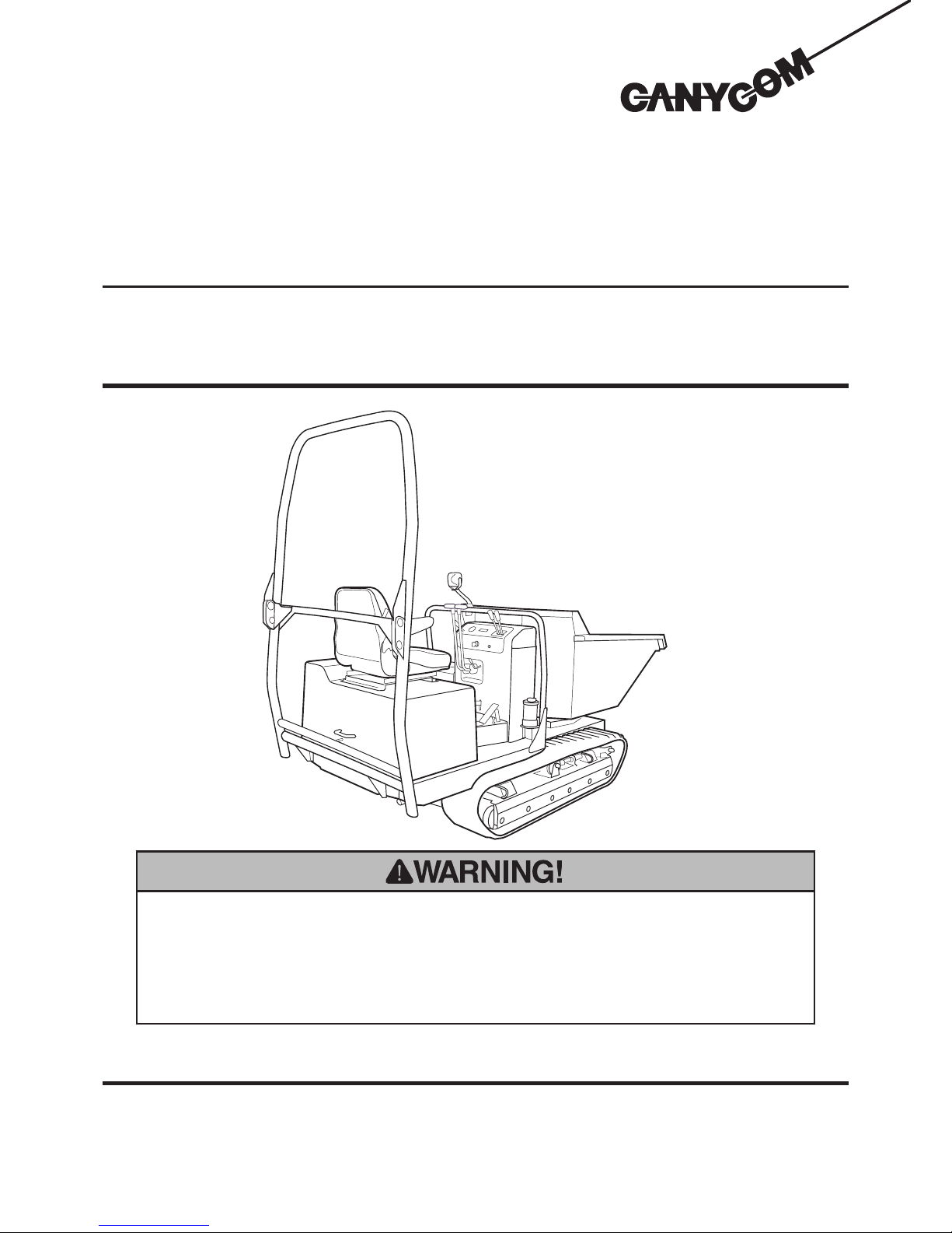
Off-road Rubber Track Dumper
S160
Operator's Manual
3683 5101 002
Page 2

http://www.canycom.co.jp/
■
Sales Headquarters TEL +81-(0)943-75-2195 FAX +81-(0)943-75-4396
■
Foreign Trade Center
TEL +81-(0)3-3552-6277 FAX +81-(0)3-3552-6288
All rights reserved. Unauthorized use or reproduction of this material is prohibited.
Authorized Dealer
CHIKUSUI CANYCOM, INC.
Page 3

Notice to Users and Maintenance Personnel
• This machine can be very dangerous if the safety precautions in this manual
and on the labels attached to this machine are not followed. Read and
understand this manual and the safety labels on the machine thoroughly before
using this machine. Always follow the instructions and safety precautions, or
serious injury or death could result.
• This machine should only be used for its intended purpose: hauling and
dumping. Any other use could be dangerous.
• This machine may not be operated on public road or what is considered to
be public road. It is the sole responsibility of the operator to consult the local
regulations.
• Do not modify this machine, or do not operate this machine with the safety
covers removed or open. A serious accident could result.
Thank you for purchasing this machine.
This manual provides information needed for safe and effective use of this machine to
those who operate or maintain the machine. Make sure to read and understand the manual
thoroughly before operating this product. Also make sure to read the separate operator's
manual for the engine.
• Store this manual in a safe, accessible place for easy reference.
Page 4
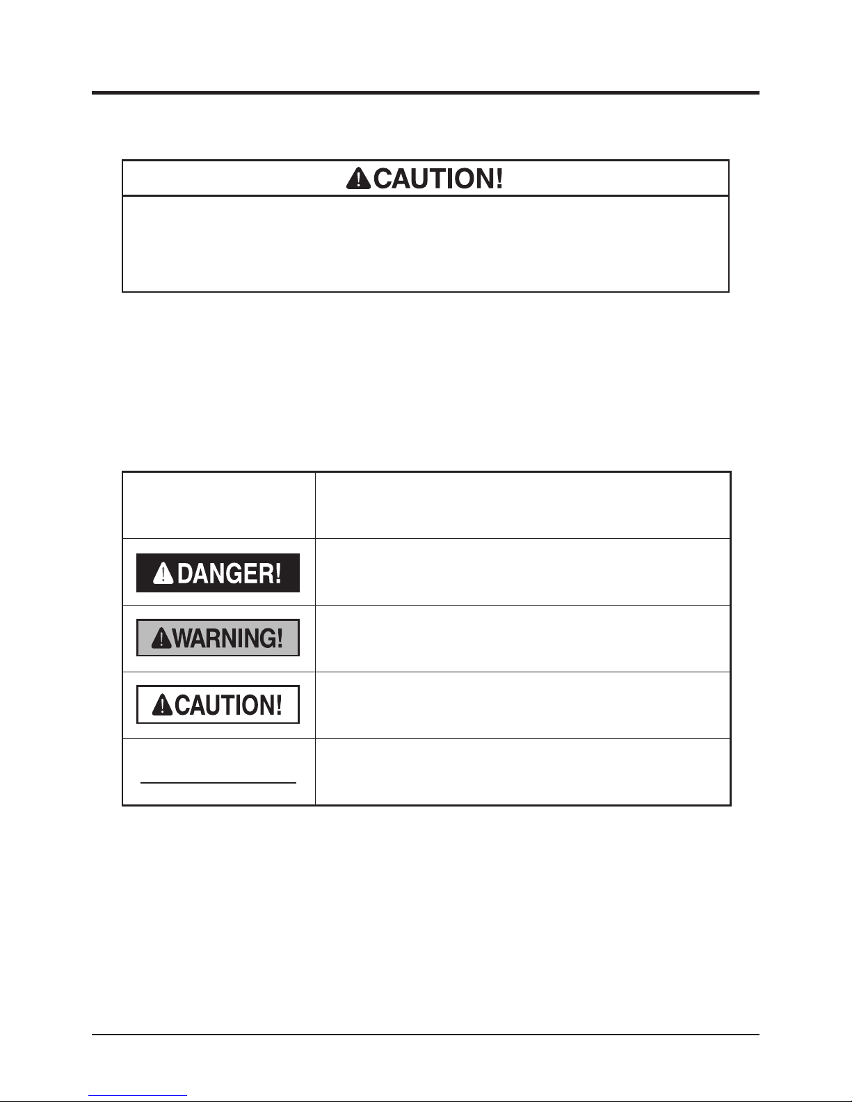
Warning Term Denition
Indicates an imminently hazardous situation which will result
in death or serious injury if the user does not follow the
procedures or the instructions.
Indicates a potentially hazardous situation which could result
in death or serious injury if the user does not follow the
procedures or the instructions.
Indicates a potentially hazardous situation which could result
in minor to moderate injury or damage to the machine if the
user does not follow the procedures or the instructions.
Indicates important information which needs particular
attention.
In this manual, the following four warning terms are used to signal the four levels of hazard
(or seriousness of possible accidents). Read and understand what they mean and always
follow the instructions in this manual.
Warning Terms Used in this Manual
NOTE
Notice to Owner
• Be sure that everyone who uses this machine, including those who rent or
lease this machine, receives a copy of this Operator's Manual and understands
the importance of reading and following the information in this manual.
Page 5

Warranty and After-Sales Service
Warranty
Consult your local CANYCOM dealer or our company’s sales department regarding service
orders or any questions or problems that may arise when using this machine. Please make
sure to have the product name, serial number, and the make and type of the engine handy at
the time of contact. The model and serial number can be found on the model label as shown
below, and the make and type of the engine can be found in Chapter5 "Specications" of this
manual (Page13).
After-Sales Service
Location of Model Label Model Label
The replacement or repair parts for this product shall remain available for seven years after
the production of this type of machine is discontinued.
Availability of Spare Parts
3683M-0005-020E
3683M-0005-010E
Location of Model Label
CHIKUSUI CANYCOM, INC. guarantees this product, based on the terms of warranty. A
copy of this warranty is reproduced in the back of this manual.
Page 6

Contents
1. Safety 1
Safety Labels . . . . . . . . . . . . . . . . . . . . . . . . . . . . . . . . . . . 1
Safety Precautions . . . . . . . . . . . . . . . . . . . . . . . . . . . . . . . 3
Training . . . . . . . . . . . . . . . . . . . . . . . . . . . . . . . . . . . . . . . . . . . . . . . . . . . . . . . 3
Preparation . . . . . . . . . . . . . . . . . . . . . . . . . . . . . . . . . . . . . . . . . . . . . . . . . . . . 4
Operation . . . . . . . . . . . . . . . . . . . . . . . . . . . . . . . . . . . . . . . . . . . . . . . . . . . . . . 4
Servicing . . . . . . . . . . . . . . . . . . . . . . . . . . . . . . . . . . . . . . . . . . . . . . . . . . . . . . 9
2. Controls and Components 10
Name and Function of Controls . . . . . . . . . . . . . . . . . . . 10
3. Specications 13
Product Specications . . . . . . . . . . . . . . . . . . . . . . . . . . 13
Contents of the Tool Bag . . . . . . . . . . . . . . . . . . . . . . . . 14
4. Operation 15
Preparation . . . . . . . . . . . . . . . . . . . . . . . . . . . . . . . . . . . . 15
Pre-start up Inspection . . . . . . . . . . . . . . . . . . . . . . . . . . . . . . . . . . . . . . . . . 15
Checking and Filling Fuel . . . . . . . . . . . . . . . . . . . . . . . . . . . . . . . . . . . . . . . 15
Using ROPS (on ROPS Model) . . . . . . . . . . . . . . . . . . . . . . . . . . . . . . . . . . . 16
Adjusting Seat . . . . . . . . . . . . . . . . . . . . . . . . . . . . . . . . . . . . . . . . . . . . . . . . 17
Using Seat Belt (on ROPS Model) . . . . . . . . . . . . . . . . . . . . . . . . . . . . . . . . 18
Page 7

Driving . . . . . . . . . . . . . . . . . . . . . . . . . . . . . . . . . . . . . . . . 19
Starting . . . . . . . . . . . . . . . . . . . . . . . . . . . . . . . . . . . . . . . . . . . . . . . . . . . . . . 19
Driving . . . . . . . . . . . . . . . . . . . . . . . . . . . . . . . . . . . . . . . . . . . . . . . . . . . . . . . 24
Stopping . . . . . . . . . . . . . . . . . . . . . . . . . . . . . . . . . . . . . . . . . . . . . . . . . . . . . 27
Parking . . . . . . . . . . . . . . . . . . . . . . . . . . . . . . . . . . . . . . . . . . . . . . . . . . . . . . . 28
Working . . . . . . . . . . . . . . . . . . . . . . . . . . . . . . . . . . . . . . 29
Dumping and Turning Bucket . . . . . . . . . . . . . . . . . . . . . . . . . . . . . . . . . . . . 29
Using Safety Prop . . . . . . . . . . . . . . . . . . . . . . . . . . . . . . . . . . . . . . . . . . . . . 31
5. Maintenance 32
Maintenance Schedule . . . . . . . . . . . . . . . . . . . . . . . . . . 32
List of Fluids and Lubricants . . . . . . . . . . . . . . . . . . . . . 37
Greasing Points . . . . . . . . . . . . . . . . . . . . . . . . . . . . . . . . 37
List of Consumables and Spares . . . . . . . . . . . . . . . . . . 38
Removing and Installing Body Panels . . . . . . . . . . . . . . 39
Engine Compartment . . . . . . . . . . . . . . . . . . . . . . . . . . . . . . . . . . . . . . . . . . . 39
Step and Control Box . . . . . . . . . . . . . . . . . . . . . . . . . . . . . . . . . . . . . . . . . . . 40
Engine . . . . . . . . . . . . . . . . . . . . . . . . . . . . . . . . . . . . . . . . 41
Engine Oil . . . . . . . . . . . . . . . . . . . . . . . . . . . . . . . . . . . . . . . . . . . . . . . . . . . . 41
Oil Filter . . . . . . . . . . . . . . . . . . . . . . . . . . . . . . . . . . . . . . . . . . . . . . . . . . . . . . 42
Air Cleaner . . . . . . . . . . . . . . . . . . . . . . . . . . . . . . . . . . . . . . . . . . . . . . . . . . . 43
Coolant . . . . . . . . . . . . . . . . . . . . . . . . . . . . . . . . . . . . . . . . . . . . . . . . . . . . . . 43
Fuel Filter . . . . . . . . . . . . . . . . . . . . . . . . . . . . . . . . . . . . . . . . . . . . . . . . . . . . 45
Page 8

Drive Train . . . . . . . . . . . . . . . . . . . . . . . . . . . . . . . . . . . . . 46
Tracks. . . . . . . . . . . . . . . . . . . . . . . . . . . . . . . . . . . . . . . . . . . . . . . . . . . . . . . . 46
HST (Hydrostatic Transmission) Fluid . . . . . . . . . . . . . . . . . . . . . . . . . . . . . 47
Transmission Oil . . . . . . . . . . . . . . . . . . . . . . . . . . . . . . . . . . . . . . . . . . . . . . . 49
Drive Belts . . . . . . . . . . . . . . . . . . . . . . . . . . . . . . . . . . . . . . . . . . . . . . . . . . . . 51
Parking Brake . . . . . . . . . . . . . . . . . . . . . . . . . . . . . . . . . . . . . . . . . . . . . . . . . 52
Greasing . . . . . . . . . . . . . . . . . . . . . . . . . . . . . . . . . . . . . . . . . . . . . . . . . . . . . 53
Electrical System . . . . . . . . . . . . . . . . . . . . . . . . . . . . . . . 54
Battery . . . . . . . . . . . . . . . . . . . . . . . . . . . . . . . . . . . . . . . . . . . . . . . . . . . . . . . 54
Fuses . . . . . . . . . . . . . . . . . . . . . . . . . . . . . . . . . . . . . . . . . . . . . . . . . . . . . . . . 56
After Use Care . . . . . . . . . . . . . . . . . . . . . . . . . . . . . . . . . 57
After Normal Use. . . . . . . . . . . . . . . . . . . . . . . . . . . . . . . . . . . . . . . . . . . . . . . 57
After Cold Weather Use . . . . . . . . . . . . . . . . . . . . . . . . . . . . . . . . . . . . . . . . . 57
Storage . . . . . . . . . . . . . . . . . . . . . . . . . . . . . . . . . . . . . . . 58
6. Troubleshooting 59
Troubleshooting . . . . . . . . . . . . . . . . . . . . . . . . . . . . . . . . 59
7. Transporting 63
Hauling . . . . . . . . . . . . . . . . . . . . . . . . . . . . . . . . . . . . . . . 63
Loading and Unloading . . . . . . . . . . . . . . . . . . . . . . . . . . . . . . . . . . . . . . . . . 63
Hoisting and Towing . . . . . . . . . . . . . . . . . . . . . . . . . . . . 65
Page 9

Warranty
Warranty Certicate is attached at the end of this manual.
* Have the warranty certicate signed and sealed after you have received and fully
understood the instructions for handling this machine and received the receipt.
Appendix
• Operator's Manual for the Engine
* Be sure to read and understand it together with this manual .
Page 10

Safety 1
-1-
Safety Labels
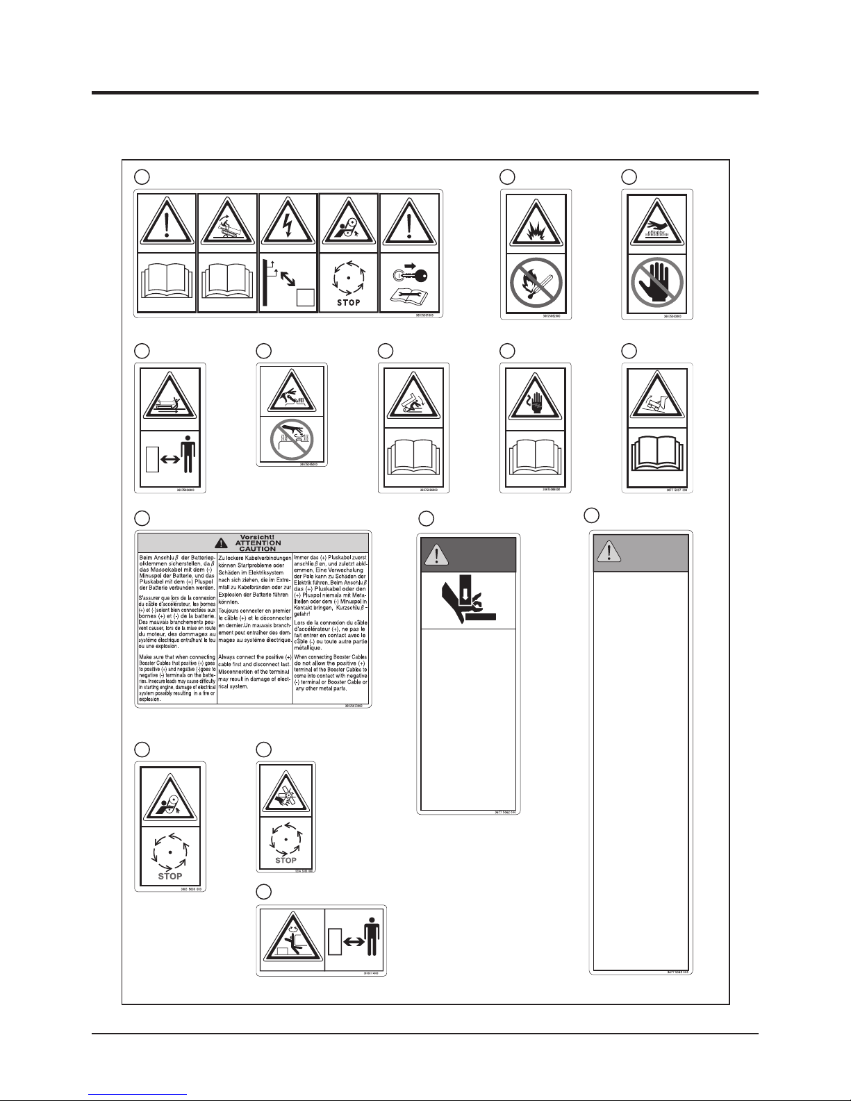
The safety labels shown on the next page are attached to the machine. See the illustration
below for the location and the illustration on the next page for the content of each label on
the machine.
• Locate all the warning labels attached to this machine. Read and follow the
instructions and precautions in them. Failure to do so could result in serious injury
or death to the operator or bystanders.
• Keep the labels clean and legible. Do not use solvents or gasoline to clean the
labels.
• Replace these labels immediately if they have been removed, have fallen off or
become illegible. Use the part number, on the label or shown in this manual, to
order a replacement label from your CANYCOM representative.
4
3683M-0101-010E
Back of Bucket
(Both Sides)
(Both Sides)
Page 11
Safety
-2-
1
CRUSH HAZARD
Keep hands away from ROPS
joint. Shearing action of ROPS
can cause serious injury or
death.
RISQUE D'ECRASEMENT
Tenir les main s éloignées du
ROPS. A ction d e cisai llement
du ROPS peut causer de
graves blessu res ou la mor t.
RISCHIO DI
SCHIACCIAMENTO
Non avvicinate le mani ai giunti
del ROLL-BAR. Pericolo di
morte o lesioni personali.
EINKLEMMGEFAHR
Ha lten Si e al le Kör per teil e
weg von Stel len, an welche n
beim Umk ippen
Einklemm gefahr besteht.
DANGER!
DANGER!
PERICOLO!
GEFAHR!
WARNING!
AVERTISSEMENT!
AVVERTENZA!
WARNUNG!
The pr otection of fered by th is
ROPS will be impair ed if it ha s
been altered, damaged , or has
been involved i n an ove rturn.
Inspect ROPS, seatbelts, and their
attachin g c omponents d aily for
cracks, d eformations or ot her
unsafe conditions. Seatbelts must
be worn whi le operating veh icle.
Failure to properly use and maintain
ROPS, se atbelts, and the ir
attaching components may result in
severe in jury or d eath to t he
operator or a bystander.
La protection offerte par ce ROPS
sera di minuée s 'il a été altéré,
endommagé ou a été impliqué lors
d'un renverseme nt. In specter le
ROPS, les ceintur es de sécurité,
leurs fixations ou autres conditions
d'inséc urité. I l faut por ter les
ceintur es de sécur ité lo rs de
l'utilisat ion du véhicule. Nég liger
l'utilisation correcte et l'entretien du
ROPS, des ceintures de sécurité et
de leurs fixations, peut entraîner de
graves ble ssures ou la mort de
l'opérateur ou du spectateur.
La p rotezione offer ta da q uesto
ROLL-BA R diminui sce qualor a
ess o ve nga mod ific ato,
danneggiato o la macchina si sia
ribaltata. Controllate giornalmente il
ROLL-BAR, le cintur e e le loro
componenti affinchè n on ci siano
rottur e, d eformazio ni o alt re
condizioni di pericolo. Le cinture di
sicurezza devono essere allacciate
durante l'utilizzo della macchina. Un
uso im proprio e la man cata
manutenzione del ROLL-BAR, delle
cinture e de lle lo ro comp onenti
possono causa re ser ie les ioni
corporee o la morte dell'operatore o
della persone circostanti.
Der Schutz des ROPS-Daches ist
nicht mehr g ewährleistet, we nn
dieses beschädigt oder verformt ist.
Überp rüfen Si e t äglich, den
Zustand d es ROPS-Dac hes, der
Sich erheits gurte und dere n
Befestig ung au f Bes chädigung,
Verschlei ss ode r Defe kt. Die
Sicherhe itsgurte m uss getragen
3683M-0101-020E
3667 5061 0001 3667 5062 0002
3667 5064 000
4 3667 5065 0005
3667 5063 000
3
3667 5073 000
9
3683 5008 000
10 5234 5063 00013
3670 5114 000
14
3677 5062 000
11
3677 5063 000
12
3677 5007 3003667 5066 000
6 3667 5068 0007
8
Page 12

Safety 1
-3-
This section contains safety precautions to follow when operating and maintaining the
machine. Read and understand the precautions in this section as well as throughout this
manual and follow them when operating or maintaining the machine. Failure to follow safety
precautions could result in property damage, serious injury or death to the operator or
bystanders.
Safety Precautions
All operators and mechanics should receive practical instructions from their employer or
renter. Such instructions should cover the following issues:
• It is essential to familiarize yourself with the controls, safety labels and the proper
use of the machine.
• Never allow people unfamiliar with these instructions to operate or service the
machine. Do not let anyone under 18 years of age to operate this machine. Local
regulations may restrict the minimum age for operating the machine. Consult your
local authority.
• The operator is responsible for the accidents or hazards caused to other people or
their property.
• This machine has a riding capacity for one person only. Do not carry passengers
other than the operator.
• Always keep in mind that care and concentration is required when working with
ride-on machines.
• Loss of control on a slope cannot be regained by the application of the brake. The
main reasons for loss of control are:
→ insufcient grip of tracks.
→ excessive speed.
→ misjudging of the ground conditions, especially slopes.
→ excessive load.
→ incorrect distribution of load.
Training
Page 13

Safety
-4-
1
Operation
• Fuel is highly ammable. See Checking and Filling Fuel, page 15, for important
safety information on handling fuel.
• Do not operate the engine in a conned space where dangerous carbon monoxide
fumes can accumulate.
• Do not touch the engine, mufer or exhaust pipe while the engine is running or soon
after it has stopped. These areas will be very hot and can cause burns.
This machine is intended for carrying sand and dirt. Carrying other materials may damage
the machine. Avoid carrying liquid concrete. That will damage the machine.
The stability of the machine is affected by the speed, rate of steering, terrain and the load.
Always pay close attention to these factors or a loss of control or tip over could occur,
resulting in property damage, serious injury or death.
General Driving
• Always wear protective footwear, long trousers, hardhat, safety glasses and ear
protection when operating or servicing the machine. Proper clothing will minimize
the chance of injury. Do not operate the equipment if you have long hair, loose
clothing, or jewelry; all of which may get tangled in moving parts. Do not operate
the machine barefoot or with open sandals.
• Prepare beforehand the working rules and procedures such as signaling and trac
control for the work place. Following such rules will reduce the risk of accidents.
• Never handle fuel or grease, service the engine, or recharge the battery in the
presence of re or spark.
• Perform the daily pre-startup inspection (see Preparation, pages 15-18) before
starting the machine. Repair or replace damaged parts before starting the machine.
Preparation
Page 14

Safety 1
-5-
• Do not operate the machine under the inuence of alcohol or drugs. Do not operate
the machine when you are tired, ill, or not feeling well.
• Always check for obstacles before operating on new terrain.
• Before starting the engine and moving the machine, scan around your surroundings
and make sure all persons and other vehicles are a safe distance away from the
machine. Sound the horn to warn bystanders.
• On the machine equipped with the optional ROPS, always keep the ROPS in the
extended position when in use. Fold the ROPS only when it is absolutely necessary
to do so when transporting the machine.
• On the machine equipped with the ROPS, always wear the seat belt when in use.
• Always stay seated in the operator's seat when driving the machine. Never operate
the steering lever off of the machine.
• On a slippery surface, travel slowly and exercise caution to reduce the chance of
skidding or sliding out of control. Never operate on ice.
• Always make certain that there is no obstacle or a person behind the machine when
backing up. After conrming that it is safe to back up, move slowly and avoid sharp
turns.
• To reduce the risk of tip over, pay special attention when encountering an obstacle
or a slope, or when braking on a slope or during a turn. See Driving on a Slope on
the next page.
• Never attempt to drive over a large obstacle such as rock or fallen tree.
• Always travel slowly and use extra caution when operating on unfamiliar terrain. Be
alert when traveling on changing terrain.
• Never operate on terrain that you are not comfortable with. Avoid terrain that is so
rough, slippery or loose that you feel like you could tip over.
Page 15

Safety
-6-
1
Driving on a Slope
• Always follow proper procedures for driving on a slope as described in this manual.
• Driving on a slope in a wrong manner can cause a loss of control or a vehicle tip
over. Check the terrain carefully before attempting to drive on a slope.
• Never drive on a slope that you are not comfortable with. Avoid a slope that is so
rough, slippery, or loose that you feel like you could tip over.
• When driving up a slope, proceed at a steady rate of speed and throttle position.
• Never move the throttle lever or the control lever suddenly.
• Never use on a slope steeper than 20 degrees.
• Driving on a slope can be dangerous. It can result in a tip over and cause
serious injury or death. Take the following precautions.
• Do not operate the machine near the edge of a cliff, an overhang or a slide area.
• Do not make sudden maneuvers. A sudden start, stop, or turn can make the machine
lose control and could cause a tip over. Be especially cautious when traveling on
soft or wet ground.
• Drive at a safe speed, taking into account the surface gradient, surface conditions
and load.
• Use an observer to help direct the machine when the visibility is poor, terrain is
rugged or hilly, or maneuvering room is limited. The observer should be able to see
the machine and its immediate surroundings, and should give pre-arranged signals
to direct the operator.
Page 16

Safety 1
-7-
• If the engine stalls or loses traction during a climb and cannot make it to the top
of the slope, do not try to turn the machine around. Carefully back down slowly,
straight down the slope.
• Drive straight up or down slopes. Avoid turning on a slope.
• When going over the top of a slope, go slow; an obstacle, a sharp drop, or another
vehicle or person could be on the other side of the crest.
• Avoid driving the machine across a slope.
• Without a load, drive the machine backwards up a slope (operator's seat toward the
top) when climbing, and drive it forward when going down a slope.
• With a load, drive the machine forward up a slope (operator's seat away from the
top) when climbing, and drive it backwards when going down a slope. Be especially
cautious when operating on a slope with a load.
• When driving down a slope, use the steering levers so that the machine travels
down at the minimum speed. Use the engine speed to help keep the machine speed
low.
Loading and Driving with a Load
• The maximum payload for this machine is 15.7kN (1600kg). Do not exceed this
maximum payload under any circumstance.
• Do not operate on a slope steeper than 20 degrees when carrying a load. Do not
carry more than 800 kg when operating on a slope between 15 and 20 degrees.
• Load cargo in the bucket so the weight is evenly distributed. When carrying a
cargo, strap the cargo to the load deck to prevent the cargo from shifting. Ensure
that cargo does not obstruct the operator's eld of view.
• When carrying a load, drive at a reduced speed. Allow a greater distance for
braking.
• Before crossing a bridge or an overpass, make certain that the total combined
weight of the machine, the load and the driver is within the stated weight limit for
the bridge or the overpass. Then, proceed carefully and at a constant speed.
Page 17

Safety
-8-
1
Parking
• Park the machine on a at, level and stable surface. Never park on a slope steeper
than 15 degrees. Avoid parking on a slope less than 15 degrees. If parking on
a slope less than 15 degrees is unavoidable, turn the bucket straight, apply the
parking brake and block the tracks at the lower end of the machine.
→ Without a load, park the machine with the operator's seat facing downhill
→ With a load, park the machine with the operator's seat facing uphill
→ Do not park sideways on a slope.
• Observe all the previous precautions for driving, driving on a slope, loading and
driving with a load, and dumping.
Dumping/Turning
When turning the bucket and dumping material from the bucket, take the following
precautions.
• Always follow the proper procedures for dumping or turining as described in this
manual.
• Only operate the bucket with the engine running.
• Always stay seated in the operator's seat when dumping or turning the bucket.
Never operate the dump or turn lever off of the machine.
• Perform the dump operation on a at, level and stable surface whenever possible.
Raising or lowering the load deck on a slope or rough terrain could result in a tip
over.
• Pay special care when dumping with the bucket turned to a side. Be tentative when
raising the bucket which is turned to a side.
• Make certain that all persons are at a safe distance away from the machine when
raising, lowering, or turning the bucket.
• Do not move the machine or leave it unattended with the bucket in the raised
position.
• Engage the bucket safety prop if you must place any part of your body under the
bucket in the raised position.
Page 18

Safety 1
-9-
Servicing
• Do not service the machine when the engine is running. If it is absolutely necessary
to run the engine while servicing, pay attention to the moving parts; keep hands,
feet, clothing and any part of the body away from any moving part, especially the
cooling fan and the belts at the side of the engine.
• Do not operate the engine in a conned space where dangerous carbon monoxide
fumes can accumulate.
• Make sure all hydraulic line connectors are tight and all hydraulic hoses and lines
are in good condition and leak-free before applying hydraulic pressure to the
system.
• Keep your body and hands away from pinhole leaks or nozzles that eject hydraulic
fluid under high pressure. Use paper or cardboard, not your hands, to search
for leaks. Hydraulic fluid escaping under pressure can have sufficient force to
penetrate the skin and cause serious injury.
• Check all fuel lines on a regular basis for tightness and wear. Tighten or repair them
as needed.
• Do not touch the engine, muffler, or exhaust pipe while the engine is running or
soon after it has stopped. These areas will be very hot and can cause burns.
• The engine must be shut off before checking or adding oil.
• Whenever you park the machine, apply the parking brake and stop the engine.
Remove the k e y whe n e ver y o u leav e the machine unattende d to p revent
unauthorized use or accidental starting.
• Diesel fuel is ammable and can be explosive. When parking the machine indoors,
make certain that the building is well ventilated and that the machine is not close to
any source of ame or spark, including appliances with pilot lights.
Page 19
Name and Function of Controls
3683M-0201-010US
Forward
Backward
1
3
4
5
7
6
8
9
14
15
16
17
11 12 13
2
10
Page 20

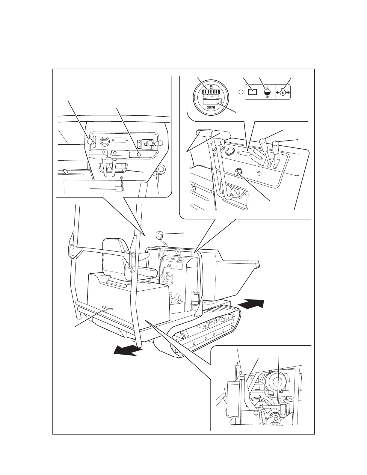
1 Dump Lever . . . . . . . . . . . . . Raises or lowers bucket.
2 Turn Lever . . . . . . . . . . . . . . Turns bucket.
3 Main Switch . . . . . . . . . . . . . Main Switch is used to start or stop the engine.
4 Steering Levers . . . . . . . . . . Steering Levers are used to control the traveling direction
(forward or backward) and speed of the tracks.
5 Parking Brake Pedal . . . . . . Parking Brake Pedal is used to park the machine securely.
6 Parking Brake Lock Lever . . Parking Brake Lock Lever is used to lock or release
Parking Brake.
7 Throttle Lever . . . . . . . . . . . . Throttle Lever is used to control the engine speed.
8 Horn Button . . . . . . . . . . . . . Pressing this button sounds the horn. Use this for warning
during traveling or signaling during operation.
9 Fuel Gauge . . . . . . . . . . . . . . Displays the amount of fuel in the tank.
10 Hour Meter . . . . . . . . . . . . . . Hour Meter displays and records the total amount of time
the machine has been in use, in the unit of 0.1 hour.
11 Battery Warning Lamp . . . . . Lights up when Main Switch is turned to the [ | (run)]
position. If there is no problem, it goes off when the engine
is started. If a problem with battery charge system is
detected when the engine is running, it lights up.
12 Coolant Temperature . . . . . . It lights up when the coolant temperature is beyond normal
operating range.
13 Oil Pressure Warning . . . . Lights up when Main Switch is turned to the [ | (run)]
position. If there is no problem, it goes off when the engine
is started. If a low oil pressure is detected when the engine
is running, it lights up.
Lamp
Warning Lamp
Page 21

Controls and Components
-12-
2
14 Work Light . . . . . . . . . . . . . . Work Light provides illumination for operation in the dark.
It is turned on or off by the switch on its back.
15 Engine Cover Latch Lever . Engine Cover Latch Lever releases engine cover .
16 Clutch Lever . . . . . . . . . . . . . Disengages the clutch.
17 Fuel Cock . . . . . . . . . . . . . . . Shuts off fuel ow.
Page 22
-13-
Specications 3
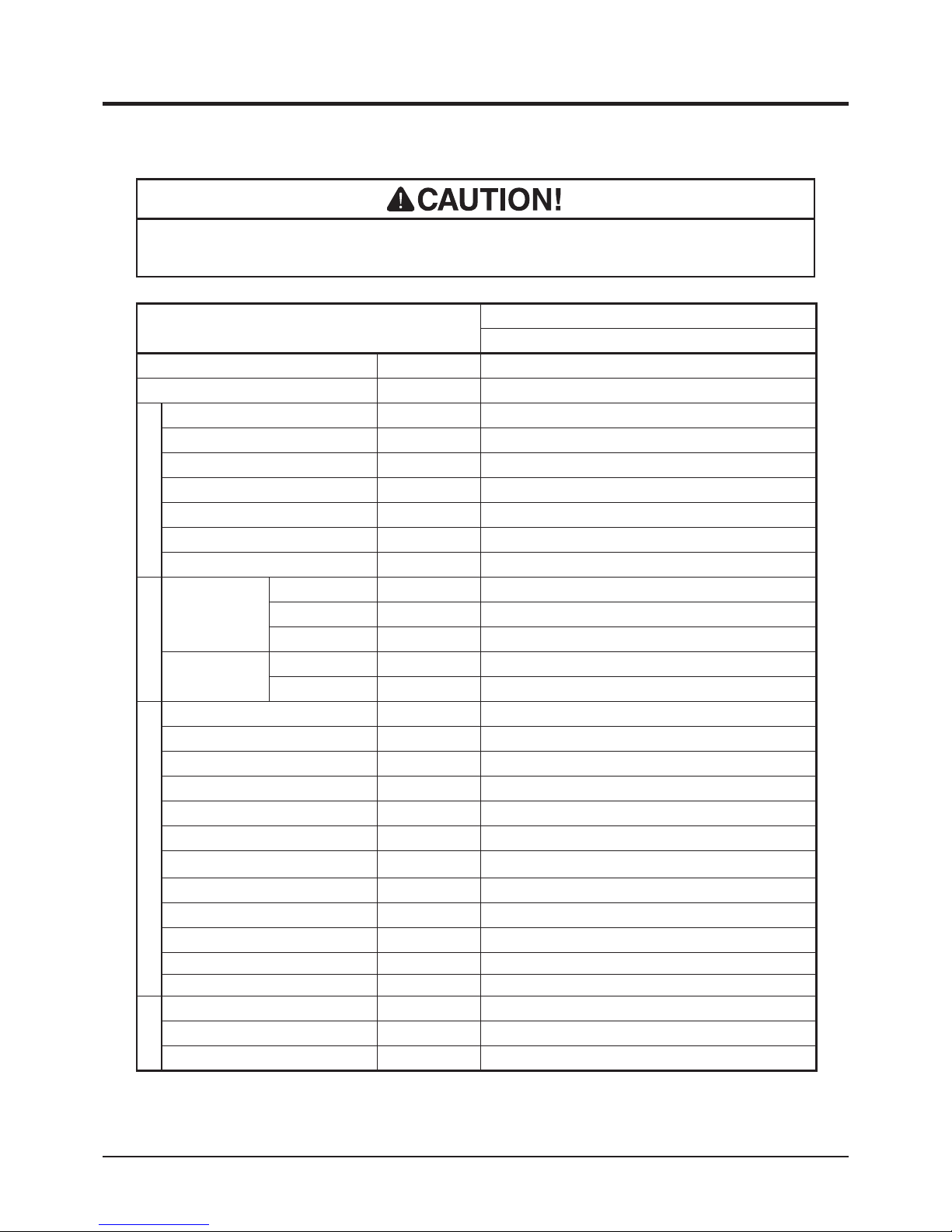
· Use this product properly after understanding its specications thoroughly.
Product Specications
Model and Type
S160
Swivel Dump
Machine Mass kg
1340 [1400]
Maximum Payload kN(kgf) 15.7(1600)
Dimensions
Overall Length mm
2850 [2940]
Overall Width
mm
1120 [1150]
Overall Height mm
1575 [2385]
Track Contact Length
mm
1195
Track Gauge
mm
840
Ground Clearance
mm
160
Loading Deck Height
mm
630
Loading Deck
Inside
Dimensions
Length
mm
1475
Width
mm
1010
Height
mm
550
Payload
Struck m
3
0.6
Heaped m
3
0.74
Engine
Model Kubota D1105-E3B
Type Water-cooled 4-cycle Diesel, in-line 3 cylinder
Cylinder (Bore×Stroke)
mm
78X78.4
Displacement cm
3
1123
Rated Output kw(PS) 15.1(20.5)
Maximum Torque N•m(kgf•m) 70.3(7.2)
Starter System Electric
Fuel Diesel No.2-D (ASTM D975)
Fuel Consumption
g/kW•h(g/PS•h)
255(190)
Fuel Tank Capacity L 22
Oil Capacity L 3.3
Coolant Capacity L 3.5 (excluding reservoir)
Electrical
Battery Type 95D31R
Battery Capacity V/AH 12/65
Working Lamp V/W 12/18.4
*[ ] The gure in the brackets indicates when ROPS is installed.
Page 23
Specications
-14-
3
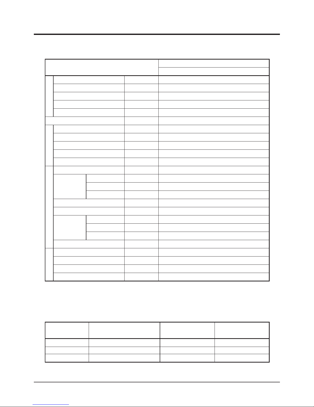
Model and Type
S160
Swivel Dump
Speed km/h 0-7.0
Minimum Turning Radius m 3.2
Gradability Degrees 25(Empty)
Operating Temperature °C -15~40
Altitude m 0~1,500
HST Oil Capacity L 32
Drive Train
Main Transmission
Twin HST
Steering
Twin HST, 2 Lever
Brakes Internally Expanding
Track Size 280×51×72
Tranamission Oil Capacity L 3.2
Dumping System
Dumping System Swivel Dump
Hydraulic
Pump
Type Gear Pump
Max. Speed
rpm 2,100
Max. Discharge
L/min 16.8
Relief Pressure MPa(kgf/cm
2
) 14.0(145)
Cylinder(Bore X Stroke) mm 465X625
Performance
Max. Angle Degrees 90
Lifting Time Sec approx. 7.4
Lowering Time
Sec approx. 5.0
Hydraulic Fluid Capacity L Shared with HST System
Swivel System
Swivel System Hydraulic (Twin cylinder)
Swiveling Angle Degrees 90(Right) - 90 (Left)
Swiveling Time Sec approx. 6.6/180°
Cylinder(Bore X Stroke) mm 50X160
*These specications are subject to change without notice.
Performance and
Operating Range
No. Content Quantitiy Note
1 Operator's Manual 1 This Manual
2
Operator's Manual for the Engine
1
3 Engine Service Tool 1
for Servicing the Engine
Contents of the Tool Bag
Page 24
-15-
Operation 4
• Keep re and spark away when handling fuel.
• Always stop the engine before refueling.
• Do not overll fuel so that fuel will not overow. Check fuel gauge when lling.
In case fuel is spilt, wipe out immediately.
Pre-start up Inspection
Preparation
Always perform an inspection before use.
Refer to Maintenance Schedule (page 32) for the inspection schedule and procedure.
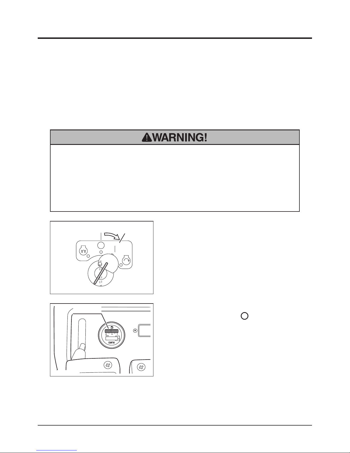
Checking and Filling Fuel
1. Insert key into main switch.
2. Turn main switch to [ | (on)] position and
wait a few seconds.
3683M-0401-010E
Off
On
Checking Fuel
3683M-0401-020E
Fuel Gauge
3. Check fuel gauge.
4. Turn main switch to [ (off)] position and
remove key.
Page 25
Operation
-16-
4
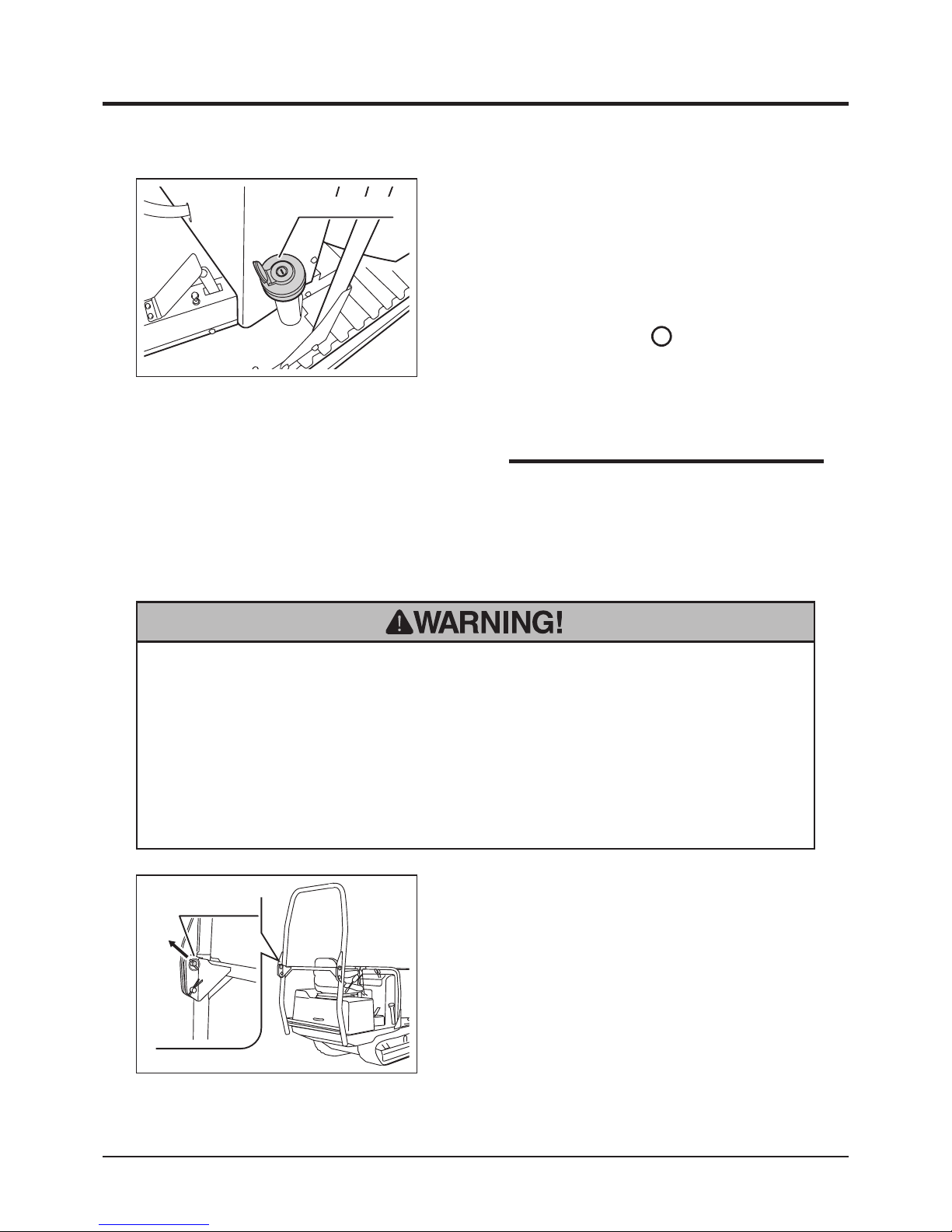
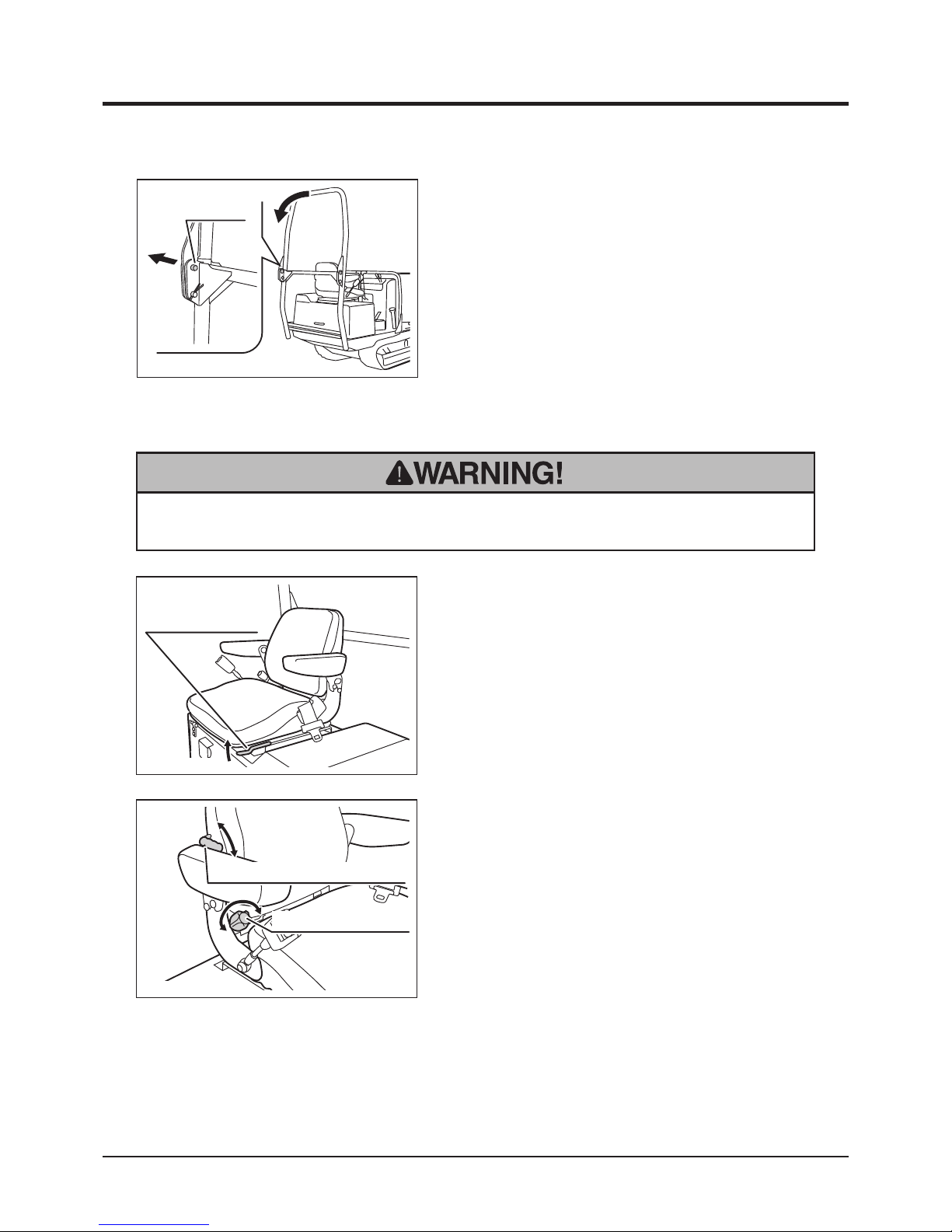
• On machine equipped with optional ROPS, always keep ROPS in the extended
(unfolded) position when riding the machine. Folding feature is provided for the
convenience of transporting the machine.
• Stay clear of ROPS when folding it. Upper portion of ROPS may fall.
• Beware of the pinch points when extending or folding ROPS.
Using ROPS (on ROPS Model)
1. Pull off security pin from ROPS lock pin.
3683M-0401-060E
Security Pin
Unfolding/folding ROPS
• Fuel : Diesel Fuel No.2-D (ASTM D975)
• Fuel Tank Capacity : 22L
NOTE
3683M-0401-030E
Fuel Filler Cap
1. Insert key in fuel ller cap and unlock it.
2. Open fuel ller cap and remove key.
3. Insert key in main switch and turn it to
[ | (On)] position.
4. Fill fuel. Check fuel gauge when lling.
5. Turn main switch to [ (Off)] position and
remove key.
6. Put fuel ller cap back and tighten it securely.
Insert key to lock it and remove key.
Filling Fuel
Page 26
-17-
Operation 4
2. Pull off lock pin from either side of ROPS.
3. Fold ROPS.
4. Extend and secure ROPS in the reverse
order.
3683M-0401-070E
Lock Pin
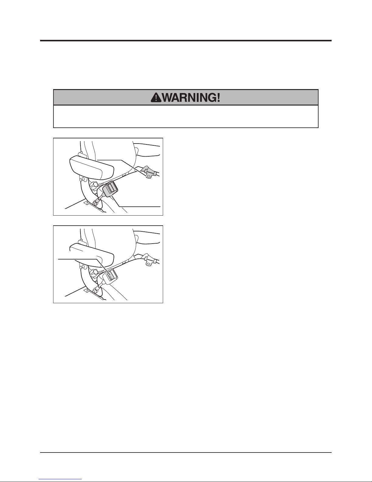
• When adjusting seat, make certain the seat is securely locked.
Adjusting Seat
1. Pull up seat adjust lever.
2. Slide seat to a comfortable position. Release
the lever.
3683M-0401-040E
Seat Adjust Lever
Sliding seat
1. Turn seatback adjust knob to adjust the
angle of seatback.
2. Turn seatback firmness adjust lever up or
down to adjust the rmness of seatback.
3683M-0401-050E
Seatback Firmness Adjust Lever
Seatback Adjust Knob
Adjusting seat back
Page 27
Operation
-18-
4
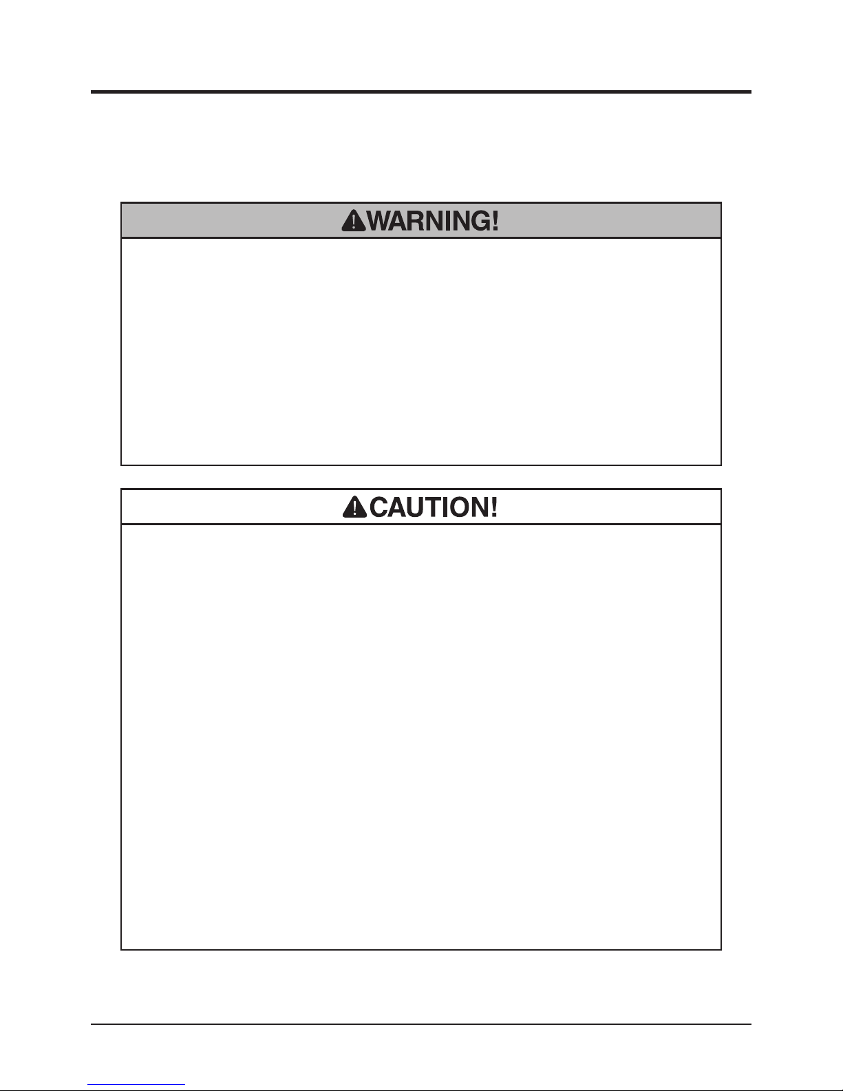
1. Adjust seat (Page 17).
2. Pull seat belt from reel and insert it into seat
belt buckle.
3683M-0401-080E
Seat Belt
Seat Belt Buckle
Fastening seat belt
1. Press release button to unfasten seat belt.
3683M-0401-100E
Release Button
Unfastening seat belt
Using Seat Belt (on ROPS Model)
• On machine equipped with optional ROPS, Always wear seat belt.
Page 28
-19-
Operation 4
Driving
• Always start and run the engine in a well ventilated place.
• Always make certain of the safety of your surroundings when starting the
engine.
• An engine that has been running is very hot. Avoid touching the engine and its
ancillaries, or severe burns may result.
• Do not open engine cover while engine is running.
• Do not turn the starter when the engine is running. Starter motor and/or the
engine may be damaged.
• Do not turn the starter for more than 15 seconds. If the engine does not start,
wait for 30 seconds or more before attempting to start again.
• Do not use this machine in temperatures above 40ºC or below -15ºC. This
machine cannot perform adequately in these temperature ranges. Using this
machine under such conditions may result in an accident or cause damage to
the machine.
• In the winter or cold climate, warm up the engine thoroughly before driving
the machine. A cold engine delivers poor performance, which may result in an
accident. It also causes excessive wear.
• Do not use this product in dusty places such as desert. Dust may clog the air
cleaner or enter the engine, which may reslt in loss of performance and an
accident. It also causes excessive wear.
Starting
Page 29
Operation
-20-
4
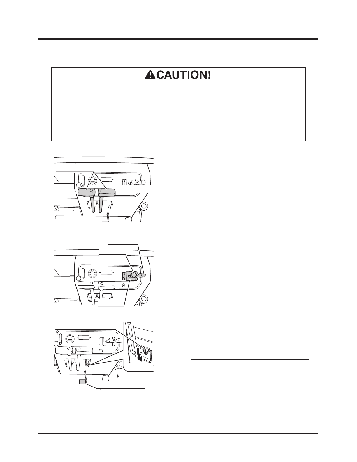
1. Make sure steering levers are in the neutral
position.
2. Make sure dump and turn (swivel) levers are
in the neutral position and lock plate is in
the locked position (around the base of the
levers).
3683M-0402-010E
Steering Levers
Neutral Position
3683M-0402-020E
Turn Lever
Dump Lever
Lock Plate
3. Depress parking brake pedal fully with
parking brake lock lever pushed down to
engage parking brake.
• The engine cannot be started unless the
steering levers are neutral and the parking
brake is engaged. This is due to a safety
feature on this product.
3683M-0402-030E
Parking Brake Lock Lever
Parking Brake Pedal
NOTE
Normal Starting
• Do not use this machine in the altitude above 1500m in its original conguration.
This machine cannot perform adequately above that altitude. Using this
machine under such conditions may result in an accident or cause damage to
the machine. If you need to use this machine above that altitude, contact your
CANYCOM representative.
Page 30
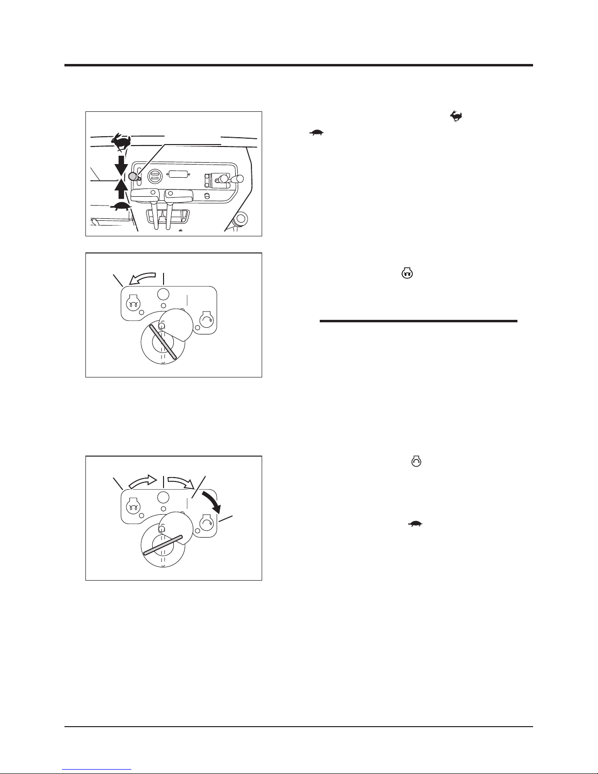
-21-
Operation 4
4. Set throttle lever in between [ (fast)] and
[ (slow)] positions.
3683M-0402-040E
Throttle Lever
7. Turn main switch to [ (start)] position to
start the engine. Once the engine starts,
re lea se key imm edi ate ly; sw i tc h wi l l
automatically return to [ | (on)] position.
8. Move throttle lever to [ (slow)] position.
3683M-0402-060E
Off
Start
On
Preheat
5. Insert key into main switch.
6. Turn main switch to [ (preheat)] position.
3683M-0402-050E
Preheat
Off
• Preheat engine for about 10 seconds when
sta r t ing in norm a l temp e r ature a n d for
about 20 to 30 seconds when starting in
cold weather (ambient temperature below -5
°C).
• There is no need to preheat if the engine is
already warm.
NOTE
Page 31
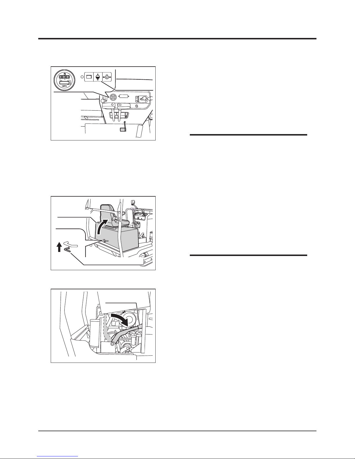
Operation
-22-
4
2. Move down clutch lever down to disengage
the clutch.
Starting in the cold
1. Move up engine cover latch lever to unlatch
and open engine cover. Raise engine cover
until it is held in place by stay.
3683M-0402-080US
Engine Cover
Engine Cover Latch Lever
3683M-0402-090E
Clutch Lever
• Drive the machine gently in the rst 40 to 50
hours of use after purchase for breaking-in.
• If any of warning lamps is lit, stop the
engine immediately and investigate the
cause.
NOTE
3683M-0402-070E
Warning Lamps
9. Make certain the warning lamps (L-R battery,
coolant temp., oil pressure) are not lit.
10. Allow the engine to warm up by running
it for 3-5 minutes without any load. (It is
not necessary when the engine is already
warm.)
• Slide the seat to the furtherst to the back
when opening engine cover.
NOTE
Page 32
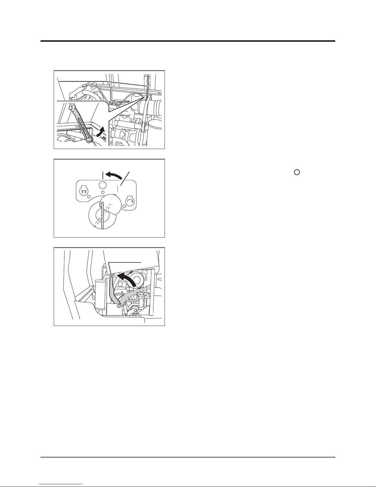
-23-
Operation 4
3683M-0402-100E
Engine Cover Stay
3. Pull the lower end of engine cover stay to
undo it. Close engine cover.
4. Start the engine by following the steps 1-10
of the normal starting procedure.
3683M-0402-110E
Off On
5. When the engine is fully warmed up, stop
the engine by turning main switch to [ (off)]
position.
3683M-0402-120E
Clutch Lever
6. Open the engine cover and raise clutch lever
to engage the clutch.
7. Close engine cover.
8. Start engine normally.
Page 33
Operation
-24-
4
• Do not allow bystanders to come near the machine when driving.
• Always make certain of the safety of your surroundings before driving; start
slow.
• Always stay seated in the operator's seat when driving the machine. Never
operate the steering lever off of the machine. This may cause the machine to
run over or crush the operator.
• Always make certain of the safety of your surroundings before turning
• Do not make sudden starts, acceralation, change of speed, change of direction,
or stop. Do not turn at speed. Avoid sudden maneuvers; this may cause the
operator to fall or to be thrown, or the machine to tip over.
• Do not turn the key to [ (off)] position while traveling. Machine can lose
stability and tip over.
• Always move the steering levers back to the neutral position before releasing.
Letting it go from other operating positions may result in sudden deceleration
and can cause the machine to tip over or the operator to fall or to be thrown.
Driving
• Do not operate steering levers when the parking brake is engaged (parking
brake pedal is pressed down). It can wear out the brake.
Page 34
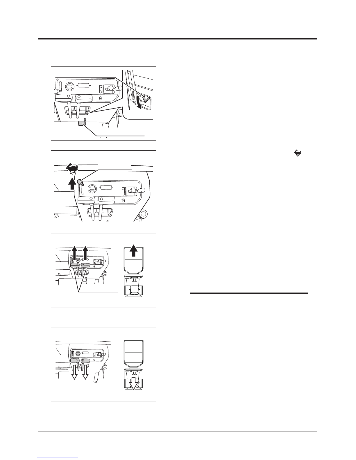
-25-
Operation 4
4. Move left and right steering levers gradually
forward together to move the machine
forward. The angle of steering levers controls
the machine speed.
5. Mo ve both ste eri ng leve rs grad ual ly
backward together to move the machine
backward. The angle of steering levers
controls the machine speed.
• See Specications (page 13) for the speed
range.
3683M-0402-150E
Steering Levers
Forward
Moving Forward
Moving Backward
NOTE
3. Move t he throttl e lever t ow ar d [
(fast)] position to increase the engine speed.
3683M-0402-140E
Throttle Lever
1. M a k e ce r ta i n of t h e sa fe t y of y o u r
surroundings.
2. Unlock parking brake by depressing parking
brake pedal and move parking brake lock
lever down.
3683M-0402-130E
Parking Brake Lock Lever
Parking Brake Pedal
3683M-0402-160E
Backward
Page 35
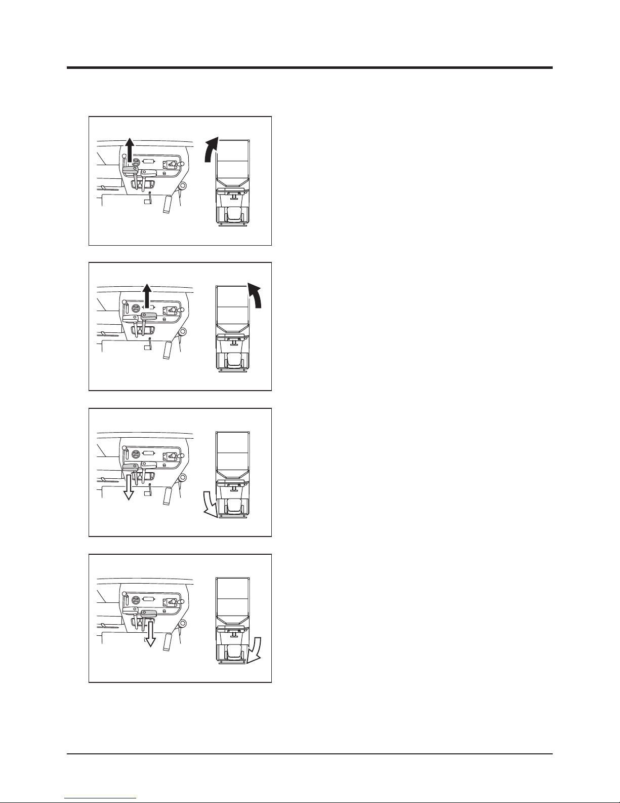
Operation
-26-
4
3683M-0402-180E
Left turn forward
Turning Backward
7. Move right steering lever gradually forward
to turn left.
8. Move left steering lever gradually backward
to turn right backwards.
3683M-0402-190E
Right turn backward
3683M-0402-200E
Left turn backward
9. Move right steering lever gradually backward
to turn left backwards.
6. Move left steering lever gradually forward to
turn right.
3683M-0402-170E
Right turn forward
Turning Forward
Page 36
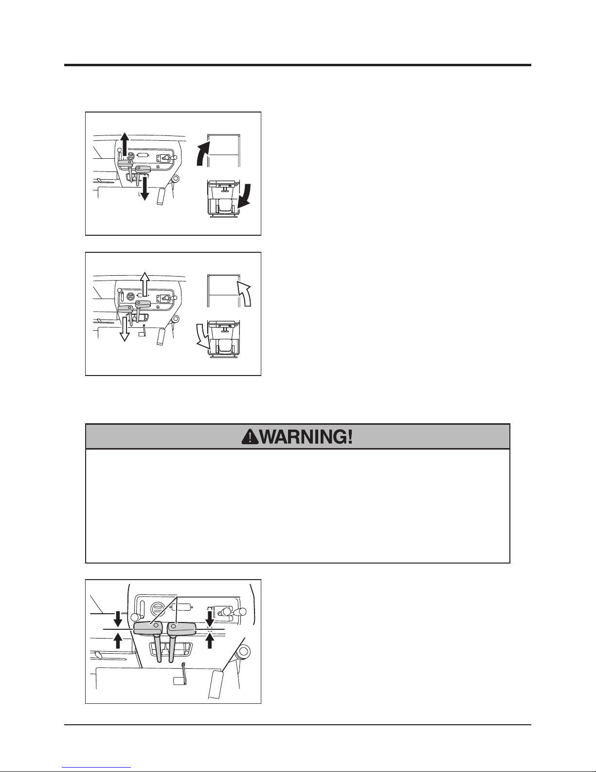
-27-
Operation 4
• Do not make a sudden stop. The machine may skid or tip over.
• Do not release steering levers suddenly. The machine may stop suddenly and
skid or tip over.
• Always park on a rm, level place. Never park on a potentially dangerous place.
Stopping
1. Move steering levers gradually to the neutral
position.
3683M-0402-230E
Steering Levers
Neutral
3683M-0402-210E
Spin-turn Right
10. Move steering levers in opposite directions
to make a turn on spot (spin-turn).
Spin-Turning
3683M-0402-220E
Spin-turn Left
Page 37
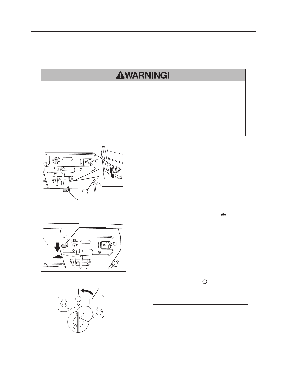
Operation
-28-
4
1. Stop the machine.
2. Depress parking brake pedal fully with
parking brake lock lever pushed down to
engage parking brake.
• Always park on a rm, level place. Never park on a potentially dangerous place.
• Avoid parking on a slope. Never park on a slope with an incline of 15 degrees or
steeper. If it is absolutely necessary to park the machine on a slope less than
15 degrees, make certain to apply parking brake firmly and block the tracks
with chocks.
Parking
3683M-0402-130E
Parking Brake Lock Lever
Parking Brake Pedal
3683M-0402-240E
Throttle Lever
3. Move throttle lever toward [ (slow)]
position to decrease the engine speed.
3683M-0402-110E
Off On
4. Turn main switch to [ (off)] position.
Remove the key from main switch.
• Leav i ng t he m ain switc h in [ | (on ) ]
position drains the battery and cause it to
discharge.
NOTE
Page 38
-29-
Operation 4
Working
• Always make certain of the safety of your surroundings when dumping or
turning bucket.
• Never operate the dumping or turning lever off of the machine. This may cause
the bucket to hit or cruch the operator or bystander.
• Avoid dumping or turning bucket on a slope. The machine may tip over.
• Always run the engine when dumping or turning bucket.
• When lowering the loaded bucket, slow the engine speed and lower the bucket
gently.
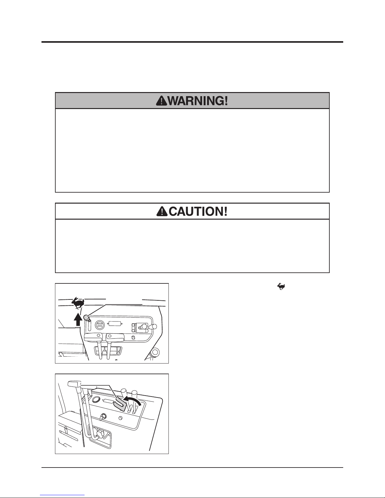
1. Move the throttle lever to [ (fast)] position
to increase the engine speed.
Dumping and Turning Bucket
2. Turn the lock plate to the side so that the
dump lever can be operated.
Raising Bucket
3683M-0403-010E
Lock Plate
3683M-0402-140E
Throttle Lever
Page 39
Operation
-30-
4
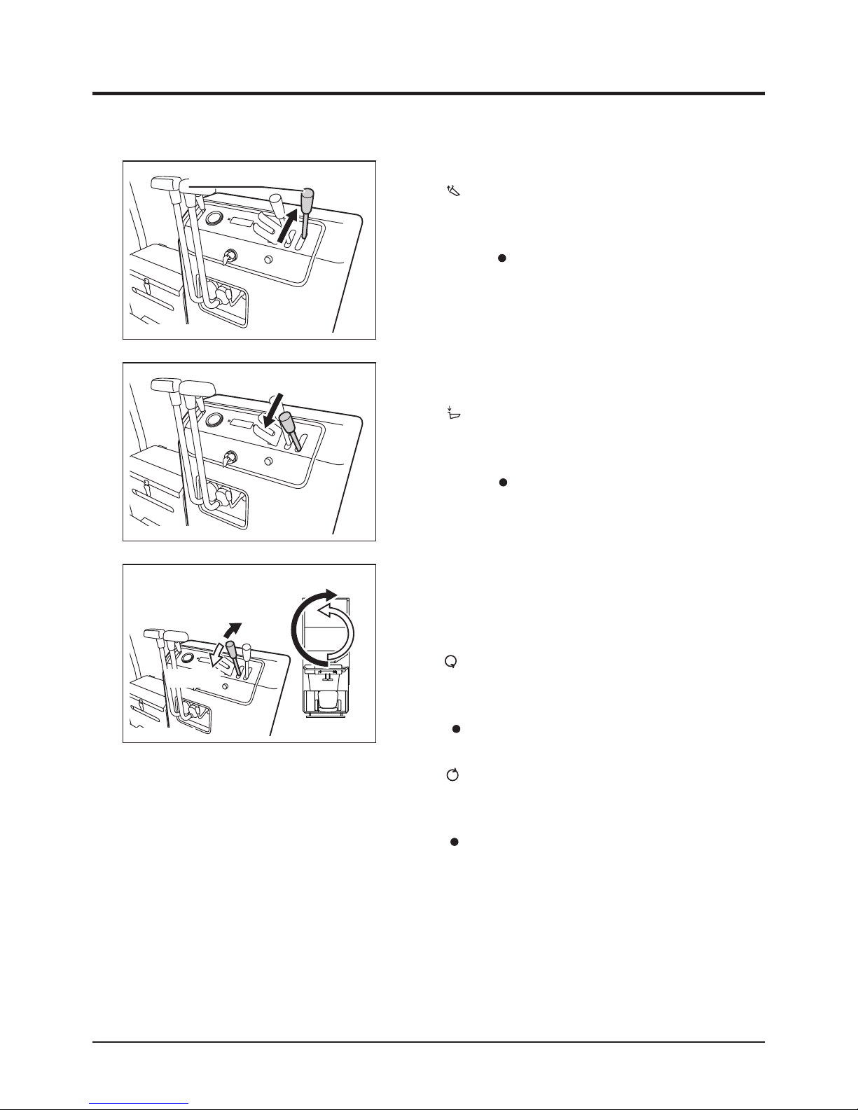
Lowering Bucket
3683M-0403-030E
5. M o v e du m p le v e r gra d u a l l y tow a r d
[ (down)] to lower bucket.
6. When bucket reaches its lower limit, a
hissing noise is heard; move dump lever
back to [ (neutral)] position.
7. Turn lock plate back in place to lock dump
lever.
8. Turn lock plate to the side so that turn lever
can be operated.
9. M o v e t u rn l e v e r g r a d ua l l y t o w ar d
[ (left)] to turn bucket left.
10. When bucket reaches its limit, a hissing
noise is heard; move turn lever back to
[ (neutral)] position.
11. M o v e tu r n l e v er g r a d u a l l y t o w a r d
[ (right)] to turn bucket right.
12. When bucket reaches its limit, a hissing
noise is heard; move turn lever back to
[ (neutral)] position.
13. Turn lock plate back in place to lock turn
lever.
Turning
3683M-0403-040E
Right Turn
Left Turn
3. M o v e du m p le v e r gra d u a l l y tow a r d
[ (up)] to raise bucket.
4. When bucket reaches its upper limit, a
hissing noise is heard; move dump lever
back to [ (neutral)] position.
3683M-0403-020E
Dump Lever
Page 40
-31-
Operation 4
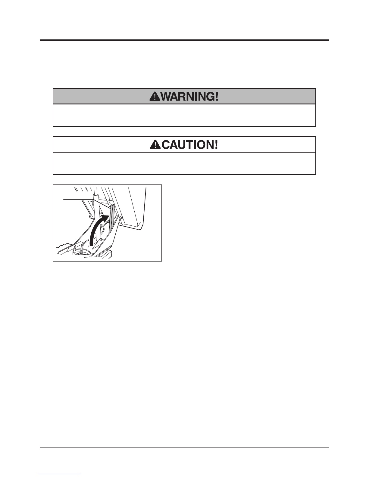
Using Safety Prop
• Place safety prop under bucket when inspecting or working under bucket.
• Make certain to undo safety prop before lowering bucket.
1. Raise bucket.
2. Hold the bucket with safety prop.
3683M-0403-050E
Safety Prop
Page 41
Maintenance
-32-
5
• Follow the scheduled maintenance as described below. Failure to do so may
result in mechanical or property damage, injury or death.
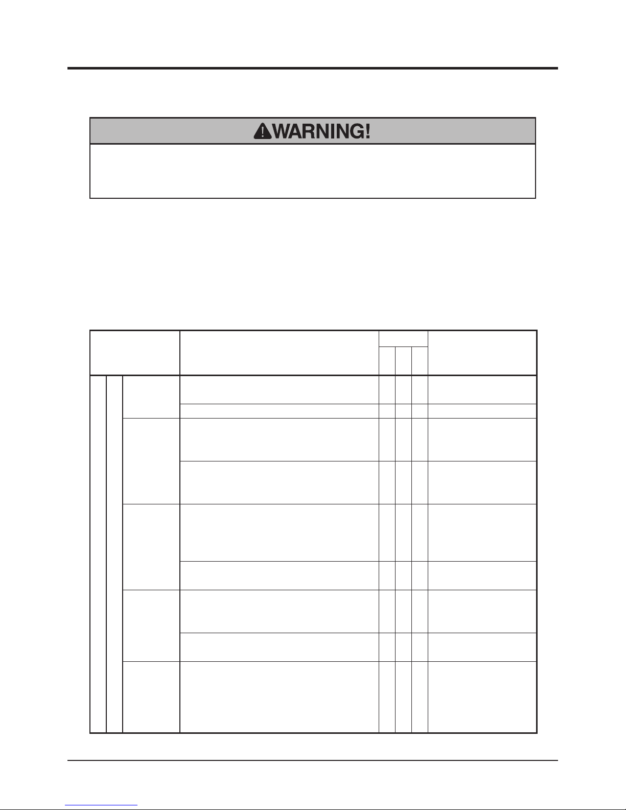
Maintenance Schedule
• Perform a pre-startup inspection (PSI) before each use, a monthly inspection once a
month, and a yearly inspection once a year.
• Some maintenance procedures described below may require special knowledge
or tools and instruments. Contact your CANYCOM representative to perform such
procedures.
Item Description
Schedule
Note
PSI
Mon
Year
Engine
General
Starting
Engine shall start easily without making any
irregular noise.
√ √ √
Glow plugs work correctly.
√ √ √
Running
Engine speed shall be set properly at idle
and at full without loading. Engine shall stay
running smoothly.
√ √
Contact your CANYCOM
representative for
inspection.
When accelerating engine, throttle lever shall
move smoothly, and engine shall accelerate
smoothly without stopping or knocking.
√ √ √
Exhaust
Warm up engine thoroughly, and observe
exhaust sound and gas from idle to fast
speed; exhaust sound shall be normal and
smoke shall not be excessive.
√ √ √
There shall be no leak in exhaust system or
mufer.
√ √
Air
Cleaner
Air cleaner case shall not be deformed or
cracked. Case lid and connecting air hose
shall be rmly in place.
√ √
Cleaner element shall be in good shape
without damage or excessive dust.
√ √
Cleaning/Replacing:
Page 43
Fasteners
Bolts and nuts fastening cylinder head,
intake and exhaust manifolds shall be tightly
fastened.
* this may be skipped if there is no gas or
water leaks found in these areas.
√
Page 42
-33-
Maintenance 5
Item Description
Schedule
Note
PSI
Mon
Year
Engine
General
Valve
Clearance
Valve clearance shall be correct.
* this may be skipped if there is no noise due
to incorrect valve clearance, and engine
runs normally.
√
Contact your CANYCOM
representative for
inspection.
Compression
Compression shall be normal
* this may be skipped if running and exhaust
condition is normal at idle and under
acceleration.
√
Contact your CANYCOM
representative for
inspection.
Engine
Mount
En gine base shall be free of cracks or
deformation.
√ √ √
Mounting bolts and nuts shall not be loose or
missing.
√ √ √
Lubrication
System
Oil shall be clean and at correct level.
√ √ √
Inspecting/Changing:
Page 41
No noticable oil leaks shall be found in head
cover, oil pan, or pipes.
√ √ √
Fuel System
There shall not be any leaks in fuel tank,
hoses, or pipes.
√ √ √
Fu el hoses shall be free of damage or
deterioration.
√ √ √
Fuel filter shall not be excessively dirty or
clogged.
√ √
There shall not be sediment or water in fuel
tank.
√ √
Injection puressure and injection condition
from the nozzle shall be normal.
* this may be skipped if running and exhaust
cond i tion is no rmal at id le and un d er
acceleration.
√
Contact your CANYCOM
representative for
inspection.
Cooling
System
Coolant shall be clean and at the correct
level.
√ √ √
Inspecting/Filling:
Page 43
There shall not be any leaks from radiator,
engine, water pump, or hoses.
√ √ √
Radiator ns shall be free of clogging.
√ √ √
Radiator cap valve shall function properly.
√
Fan belt shall be free of wear and damage,
and shall be properly tensioned.
√
Cooling fan, duct, and cover shall be free of
cracks, damage, or deformation.
√
Mounting bolts and nuts on cooling fan, duct,
and covers shall not be loose or missing.
√
Page 43
Maintenance
-34-
5
Item Description
Schedule
Note
PSI
Mon
Year
Engine
Electrical System
Charge
System
Charge system is working correctly.
√
Contact your CANYCOM
representative for
inspection.
Battery
Battery electrolyte level shall be correct.
√ √
Inspecting/Filling:
Page 55
Terminals shall be free of marked corrosion
and are tightly secured.
√ √
Wiring
Connections shall be securely connected.
√ √
Wiring shall be free of damages.
√ √
Drive Train
Clutch
Clutch sha l l not make nois e and sha l l
disengage completely when operated at idle.
√ √
Clutch shall not slip and shall engage
smoothly.
√ √
Drive Belts
Belt tension shall be properly adjusted.
√ √
Inspecting/Adjusting:
Page 51
Belt shall be free of damage, excessive
wear, or dirt; shall be free of oil or grease.
√ √
Transmission
Irregular noise or overheating shall not be
observed.
√ √ √
Oil shall be clean and filled to the proper
level.
√ √
Replacing: Page 49
There shall not be oil leaks in or around
transmission.
√ √
HST Pump
Drive the machine forward and backward,
turn left and right in both directions; machine
shall move normally and free of irregular
noise or overheating.
√ √ √
Hydraulic fluid shall be filled to a proper
level.
√ √
Inspecting/Changing:
Page 47
Hydraulic uid shall be clean and free of dirt
or contamination.
√ √
Inspecting/Changing:
Page 47
There shall be no fluid leaks in or around
uid tank.
√ √
Linkage
Rods, links, and wires in linkage shall be free
of deformation or damage.
√ √
Connections shall be free of looseness,
excessive play, or missing cotter pins.
√ √
Page 44
-35-
Maintenance 5
Item Description
Schedule
Note
PSI
Mon
Year
Undercarriage
Wheels
Sprockets
Idlers
Shall be free of cracks, defromation, or
excessive wear.
√ √ √
There shall not be excessive play in axle.
Irregular noise or overheating shall not be
observed when traveling.
√ √ √
Mounting bolt or nut shall not be loose or
missing.
√ √ √
There shall be no oil leak in or around axle.
√ √
Tracks
There shall not be marked cut, deterioration,
or wear.
√ √ √
Track shall be properly tensioned; shall not
be too loose or too tight.
√ √ √
Adjusting: Page 46
Track core shall not be missing or damaged.
√ √ √
Tension bolt shall be free of deformation or
corrosion.
√ √ √
Brake System
Parking Brake
Parking brake shall work properly.
√ √ √
Adjusting: Page 52
Parking brake shall be able to hold the
machine on a 20-degree slope.
√ √
Linkage
Rods, links, and wires in linkage shall be free
of deformation or damage.
√ √
Connections shall be free of looseness,
excessive play, or missing cotter pins.
√ √
Hydraulic System
Hydraulic
Pump
There shall be no leak in or around hydraulic
pump.
√ √
Fastening bolts and nuts shall not be loose
or missing.
√ √
No irregular vibration, noise, or heat shall
be observed when hydraulic pump is in
operation.
√ √
Amount and pressure of discharge under
load shall be within the standard range
specied by the manufacturer.
*this may be skipped if irregular vibration,
noise, or heat des c ribed abov e is not
observed.
√
Hydraulic
Valve
There shall be no leak in or around hydraulic
valve.
√ √
Page 45
Maintenance
-36-
5
Item Description
Schedule
Note
PSI
Mon
Year
Hydraulic System
Plumbing
Plumbing shall be free of cracks, damage,
twists, or deterioration.
√ √
There shall be no leaks in pipes, hoses,
joints, or seals.
√ √
Plumbing shall be mounted properly, and
fastening bolts and nuts shall not be loose or
missing.
√ √
Breather shall not be clogged.
√ √
Hydraulic
Cylinders
Shall work smoothly.
√ √
There shall be no leaks when extending and
contracting cylinder.
√ √
Extend dump cylinder fully under load
and hold. Stroke shall be within the range
specied by manufacturer.
√
Cylinder tube and rod shall be free of dents,
cracks, bends, or scratches.
√ √
Cylinder mounting pins shall be free of
damage or excessive wear.
√ √
Body, Chassis, Loading Deck
Chassis
Frame
Shall be free of cracks, deformation, or
corrosion.
√ √
Fastening bolts or nuts shall not be loose or
missing.
√ √
Body Panels
Shall be free of cracks or deformation.
√ √
Doors shall open, close, and lock properly.
√ √ √
Fastening bolts or nuts shall not be loose or
missing.
√ √
Loading Deck
Loading deck shall be raised,lowered and
turned smoothly.
√ √
Shall be free of cracks, deformation, or
corrosion.
√ √
Fastening bolts or nuts shall not be loose or
missing.
√ √
Safety Prop
Safety prop shall be free of any deformation.
√ √
Labels
Warning labels and instruction plates shall
be clean, legible, and free of damage.
√ √ √
Safety Devices
Work Lamp
Work lamp shall work.
√ √ √
Lamp lens shall be free of cracks or chipping
and water shall not be in the lamp.
√ √
Horn
Horn shall work.
√ √ √
Page 46
-37-
Maintenance 5
List of Fluids and Lubricants
Item Schedule Grade Cap. Ref.
Fuel As needed. Diesel Fuel (Diesel No2-D,
ASTM D975
22L Page 15
Engine Oil
Fill
Inspect daily. Fill as needed.
Change
Initially - After 50 hours of use.
Every 100 hours afterwards.
Diesel Engine Oil
API rating: CD or better.
SAE rating: 10W-30
3.3L Page 41
Transmission Oil
Change
Initially - After 50 hours of use.
Every 100 hours afterwards.
Gear Oil
API rating: GL-4 or 5
SAE rating: 80
3.2L Page 49
HST Fluid Change
Initially - After 50 hours.
Every 500 hours afterwards.
High viscosity index
hydraulic uid, ISO VG46
32L Page 47
Engine Coolant
Check Everyday
Add as needed
Change every 2 years
Long Life Coolant (LLC) and
pure water Mixture
3.5L
(Not including
reservor)
Page 43
Battery Electrolyte
Inspect daily. Distilled Water
- Page 54
Greasing Points
Point Schedule Grade Cap. Ref.
Greasing Points
6 months after the purchase.
Every 6 months afterwards.
Chassis Grease
- Page 53
Page 47
Maintenance
-38-
5
List of Consumables and Spares
Item Part No. Schedule Qty. Ref.
Engine
Air Cleaner Element
16271-32-93
Clean: Initially after 50 hours.
Afterwards every 100 hours.
Replace yearly or if defective.
1 Page 43
Oil Filter
T0270-16320
Initially: 50 hours.
Every 200 hours afterwards.
1 Page 42
Fuel Filter
37140051400
Replace every 450 hours or if
defective.
1 Page 45
Drive Train
Drive Belt (SC62)
08531500062
Replace if defective. 2 Page 51
Track
36732011000
Replace if defective
or reaches the wear limit.
2 Page 46
Brake Lining
73054005000
Replace if defective.
(Replace in pairs)
2 Page 52
Electrical System
Battery (40B19R)
36630651000
Replace if defective. 1 Page 54
Fuse 40A
09801004003
Replace if defective. 2 Page 56
Light Bulb
09808121844
Replace if defective. 1
Hydraulic System
Hydraulic Hoses (Dump, Turn,
Oil Cooler, HST)
Contact your
CANYCOM
representative
for parts
information.
Every 2 years
or if defective.
1
Suction Filter
36836031000
Every 500 hours. 1 Page 47
Line Filter
35706161000
Every 500 hours. 1 Page 47
• Rubber products such as the hydraulic hose deteriorate over time. Replace them
every 2 years.
• Track wear limit: 5mm of lug height
NOTE
• When replacing consumable or spare, always use CANYCOM genuine part.
Page 48
-39-
Maintenance 5
Opening Engine Cover
1. Move up engine cover latch lever to unlatch
and open engine cover. Raise engine cover
until it is held in place by stay.
Engine Compartment
Removing and Installing Body Panels
• Cut or pinch hazard exists when removing or installing body panels; beware of
sharp edges and pinch points.
• Make certain to reinstall panels and closing doors after removing or opening for
repairs or inspection.
3683M-0402-080US
Engine Cover
Engine Cover Latch Lever
Closing Engine Cover
1. Pull the lower end of engine cover stay to
undo it. Close engine cover.
3683M-0402-100E
Engine Cover Stay
• Do not open engine cover while engine is running.
• Slide the seat to the furtherst to the back
when opening engine cover.
NOTE
Page 49
Maintenance
-40-
5
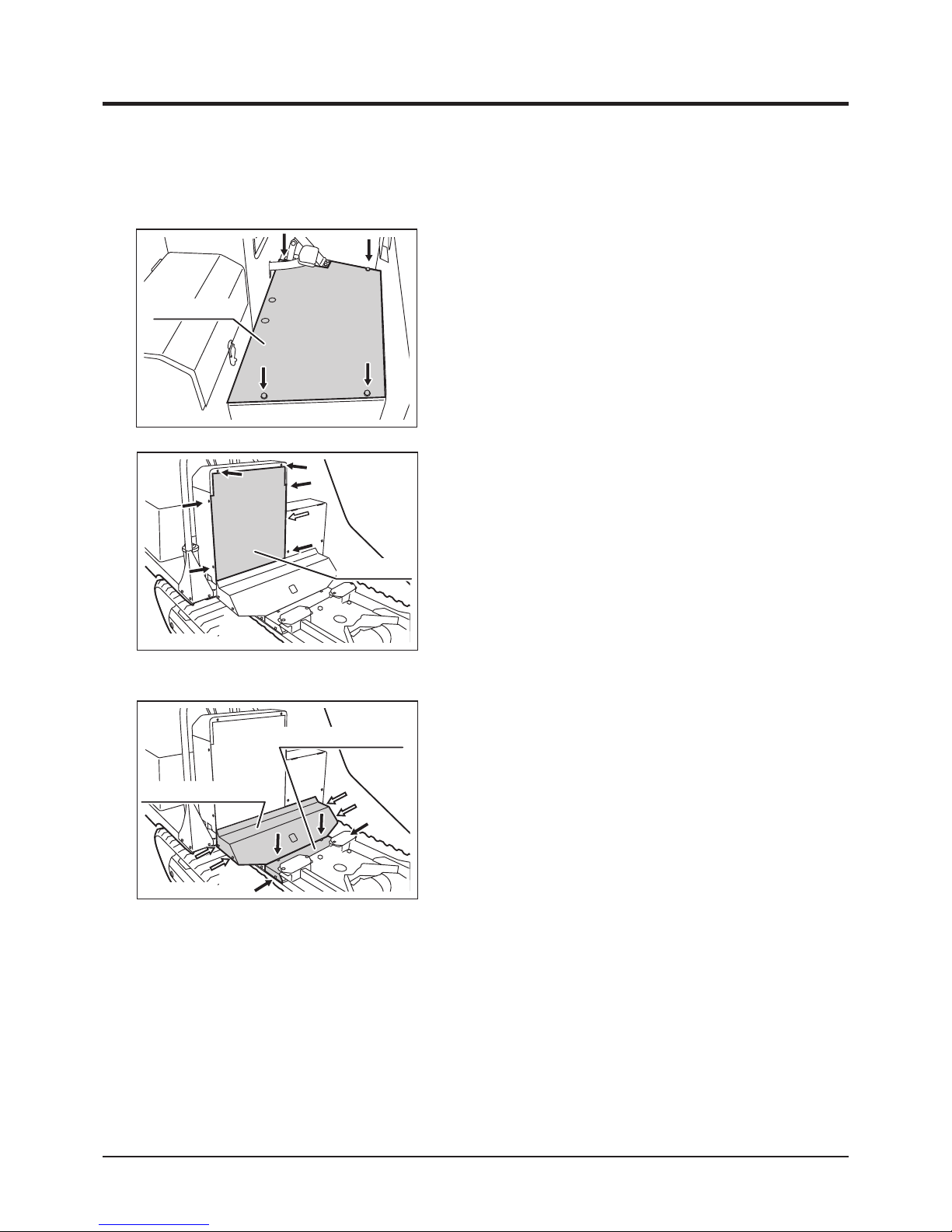
Removing Control Box Back Panel
1. Raise bucket.
2. Hold bucket with safety prop.
3. Unfasten (7) bolts (one is in the battery box)
to remove back panel.
Installing Control Box Back Panel
1. Place back panel and fasten bolts to install.
2. Undo the safety prop and lower bucket.
3683M-0505-020E
Back Panel
Removing Floor Panel
1. Unfasten (4) bolts to remove oor panel.
Installing Floor Panel
1. Place oor panel and fasten bolts to install.
3683M-0505-010E
Floor Panel
Step and Control Box
Removing Tank Cover Panels
1. Raise bucket.
2. Hold bucket with safety prop.
3. Unfasten (4) bolts that secure tank cover
panel 1 and remove the panel.
4. Unfasten (4) bolts that secure tank cover
panel 2 and remove the panel.
Installing Tank Cover Panels
1. Place tank cover panel 2 and fasten bolts to
install.
2. Place tank cover panel 1 and fasten bolts to
install.
3. Undo safety prop and lower bucket.
3683M-0505-030E
Tank Cover Panel 2
Tank Cover Panel 1
Page 50
-41-
Maintenance 5
Engine
Engine Oil
• Always stop the engine before servicing.
• An engine that has been running is very hot. Allow the engine to cool before
servicing, or severe burns may result.
• Keep re and spark away when handling fuel.
1. Park the machine on a level surface.
2. Open engine cover.
3. Follow the instructions in the Operator's
Manual for the Engine to inspect oil.
• Dispose of the drained oil properly.
• Make certain to fill the engine with correct grade of oil to the specified level.
Insufcient amount or wrong grade of oil reduces performance and may cause
permanent damage to the engine.
Inspecting
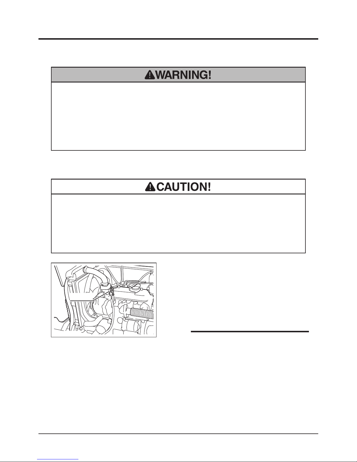
3683M-0506-010E
Dip Stick
• To obtain correct reading, check oil level
before starting, or wait about 10 minutes
after stopping the engine to allow oil to
drain back to the oil pan.
• Always check oil level on a level surface.
NOTE
Page 51
Maintenance
-42-
5
1. Remove oil ller cap.
2. Follow the instructions in the Operator's
Manual for the engine to ll oil.
3. Put oil ller cap back in place and tighten it
securely.
Filling
1. Have an appropriate oil drain pan.
2. Remove drain plug to drain oil.
3. Clean drain plug and put it back in place and
tighten it securely.
4. Fill oil.
5. Close engine cover.
Changing
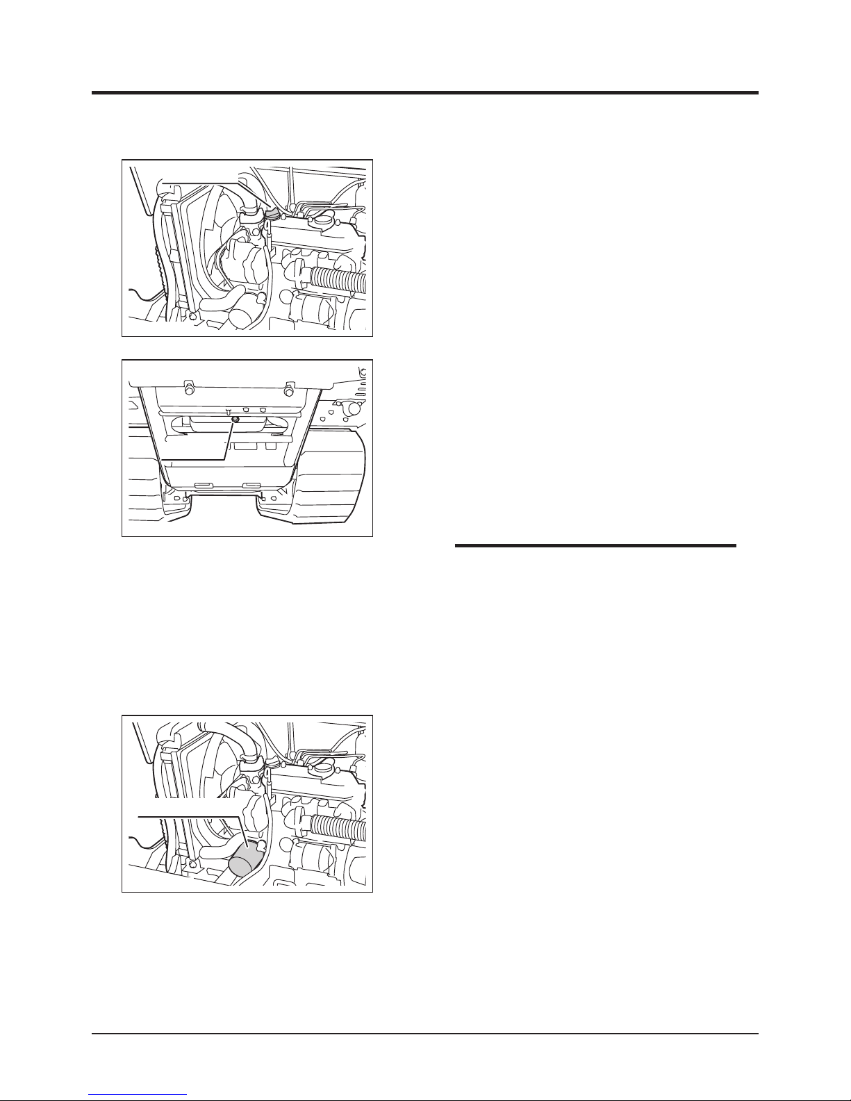
3683M-0506-020E
Oil Filler Cap
• Oil Capacity: 3.3L
• Oil to Use: Diesel Engine Oil, API rating
GL-4 or 5, SAE index 10W-30.
• Removing oil filler cap helps drain oil faster.
3683M-0506-030E
Drain Plug
NOTE
Oil Filter
1. Open engine cover.
2. Follow the instructions in the Operator's
Manual for the engine to change oil filter
cartridge.
3. Fill oil.
4. Close engine cover.
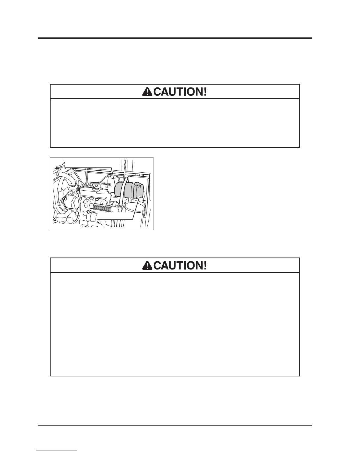
3683M-0506-040E
Oil Filter Cartridge
Page 52
-43-
Maintenance 5
Air Cleaner
• Clean air cleaner element regularly. Dirty cleaner element reduces engine
performance and life.
• Replace cleaner element if damaged.
1. Open engine cover.
2. Follow the instructions in the Operator's
Manual for the engine to inspect, clean or
change air cleaner element.
3. Close engine cover.
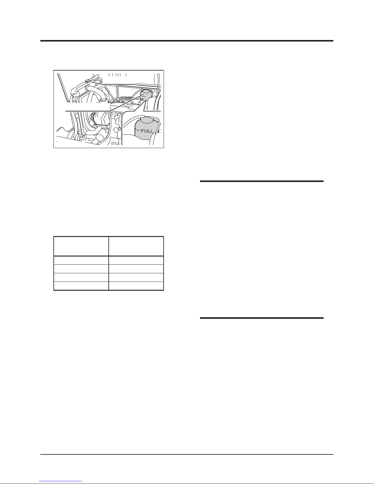
3683M-0506-050E
Air Cleaner Housing
Air Cleaner Lid
Coolant
• Do not open radiator cap when engine or radiator is hot. Opening cap when
they are still hot may release boiling coolant and cause severe burns. Wait for
engine to cool after operation (about 10 minutes) before opening.
• Tak e extr e m e care when h a ndling t h e cool a n t; anti f r eeze so l u tion i s
inammable. Avoid exposure to open ame. It is also toxic. If coolant is caught
in the eye, wash the eye clean with running water and consult a physician
immediately.
• Dispose of the drained coolant properly.
Page 53
Maintenance
-44-
5
1. Open engine cover.
2. When the engine is cold, check engine
coolant level in reservoir tank. If the level is
below [FULL] mark, add water.
3. Open radiator cap.
4. Check engine coolant level. If the level is
low, add water.
5. Put radiator cap back in place.
6. Close engine cover.
3683M-0506-060E
Radiator Cap
Coolant Reservoir
Inspecting/Filling
• When coolant temperature warning lamp
is lit, it may mean the coolant level is low.
Immediat e ly in s p ect a n d add water as
necessary.
NOTE
When this machine is shipped from the factory,
it is filled with a mixture of 40% antifreeze and
60% water. To prevent coolant from freezing, use
a mixture of water and antifreeze determined by
the minimum temperature in the operation area
using the table on the left.
Antifreeze Mixture (Reference)
Ambient
Temperature
Antifreeze
Mixture
-10 °C
30%
-15 °C
35%
-20 °C
40%
-25 °C
45%
* The value for the ambient temperature
is 5°C lower than the actual minimum
temperature.
• Antifreeze to use: Long Life Coolant (LLC).
• Use pure water to make antifreeze mixture.
NOTE
Page 54
-45-
Maintenance 5
1. Open engine cover.
2. Have an appropriate drain pan.
3. Remove coolant drain plug to drain coolant.
Wash inside radiator.
4. Put drain plug back in place and tighten it
securely.
5. Fill coolant.
6. Close engine cover.
3683M-0506-070E
Coolant Drain Plug
Changing
Fuel Filter
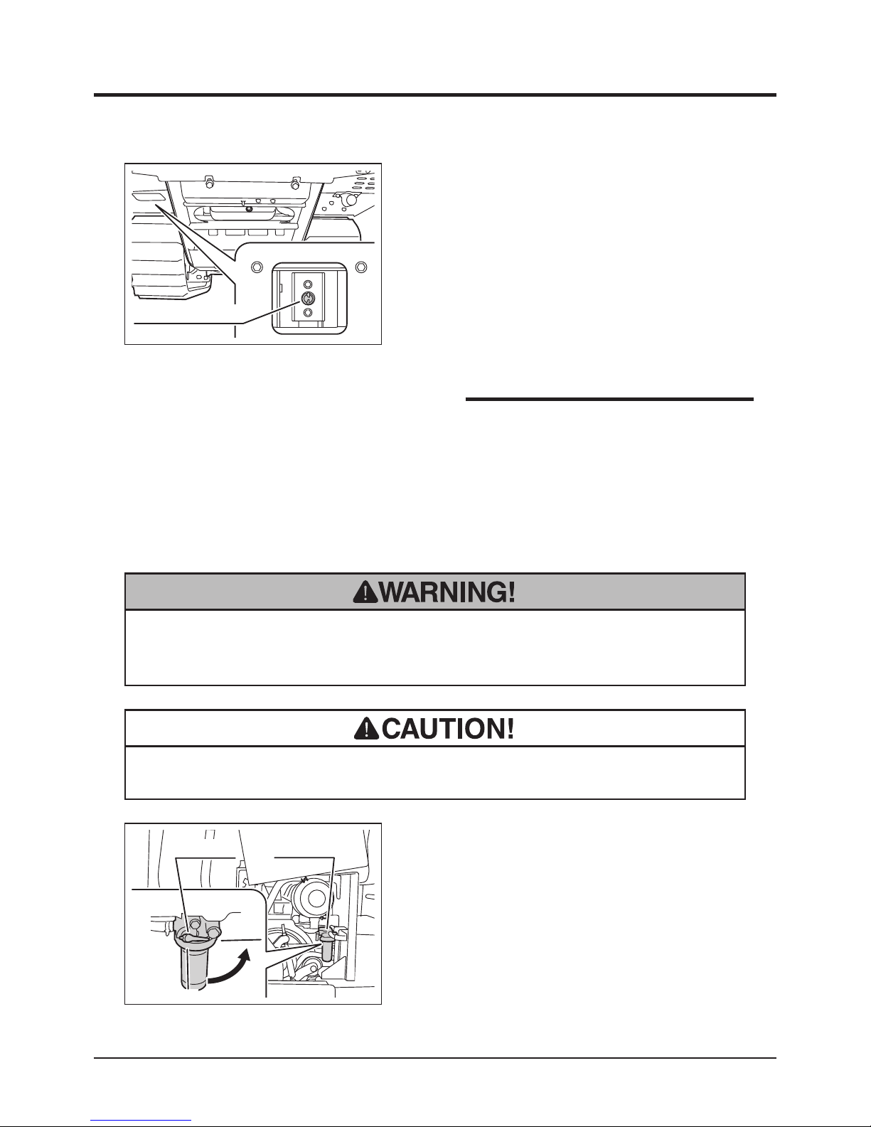
1. Open engine cover.
2. Turn fuel cock to [Off] position.
3. Follow the instructions in the Operator's
Manual for the engine to inspect, clean, or
change fuel lter.
4. Turn fuel cock to [On] position.
5. Close engine cover.
• Fuel is highly ammable. Keep re and spark away when servicing fuel lter. If
fuel is spilt, wipe immediately.
3683M-0506-080E
Fuel Filter
Off
On
Fuel Cock
Inspecting/Cleaning
• Coolant Capacity (excluding reservoir): 3.5L
• Reservoir Capacity: 0.7L
•Removing r a d i ator cap h e l p s drain the
coolant.
NOTE
• Dispose risidual fuel in fuel lter properly.
Page 55
Maintenance
-46-
5
Drive Train
• Stop the engine when servicing the drive train.
• Allow the machine to cool off before servicing. The engine is very hot after
operation and may pose a burn hazard.
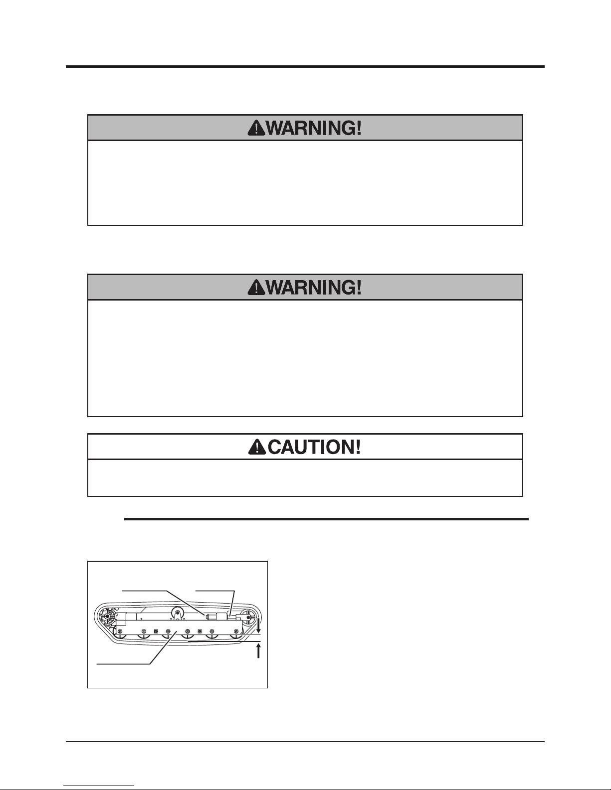
Tracks
1. Hoist the machine.
2. Inspect the clearance between track and the
track frame to be between 60 and 70mm.
Adjust tracks if the clearance is not within
this range.
Inspecting
• Hoist the machine securely when inspecting and adjusting the track. Use
hoisting slings of sufcient strength. Always use the slings of the same length
when more than one is used.
• Make certain to adjust track tension properly. Inproperly tensioned tracks may
wear or come off, resulting in property damage, serious injury or death.
3683M-0507-010E
Lock NutAdjust Nut
60 - 70mm
Track Frame
• Track stretches during its use-life. Inspect and adjust regularly.
NOTE
• Always unload the machine before hoisting.
Page 56
-47-
Maintenance 5
Adjusting
1. Loosen lock nut.
2. Adjust track with adjust bolt so that the
clearance between track and track frame at
the furthest are between 60 and 70mm.
3. Tighten lock nut
4. Lower the machine.
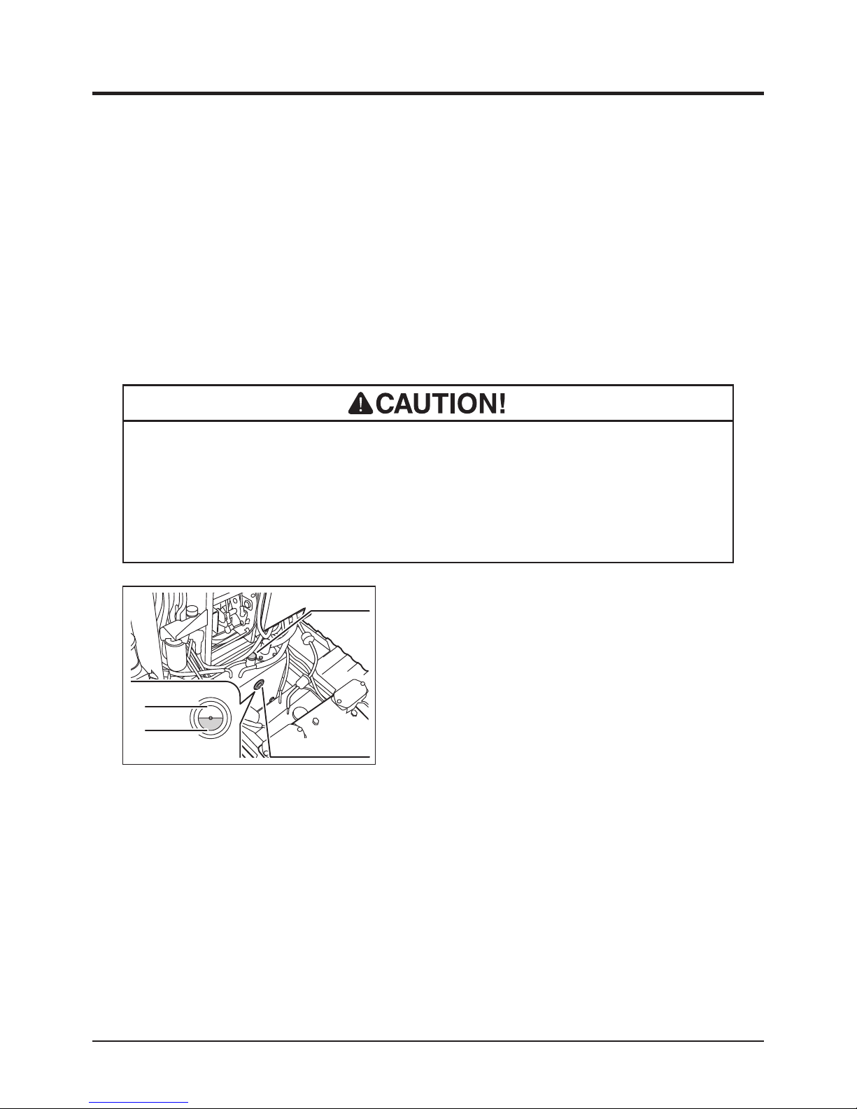
HST (Hydrostatic Transmission) Fluid
• Dispose of the drained uid properly, according to the national and local regula-
tions.
• Burn hazard; pay special attention when handling the hydraulic uid. Hot uid
may cause burns.
3683M-0507-020E
Filler Cap
Upper Limit
Lower Limit
Oil Level Window
1. Park the machine on level ground.
2. Lift the bucket and hold it with the safety
prop. (Page 31) Lock the dump lever with
lock plate.
3. Remove tank cover panels 1 and 2. (Page
40)
4. Visually inspect oil level window.
5. If the level is low, open ller cap and ll uid.
Put ller cap back in place.
6. Install tank cover panels.
7. Undo safety prop. Lower bucket.
Inspecting/Filling
Page 57
Maintenance
-48-
5
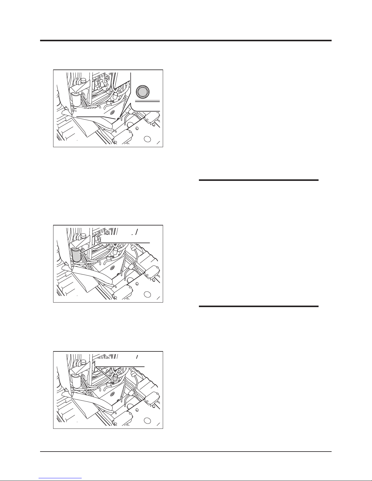
6. Remove line lter cartridge with the oil lter
wrench.
7. Have a new line lter cartridge ready. Apply
clean hydraulic uid (oil) on the cartridge oil
seal evenly.
8. Screw in the new line lter cartridge. Tighten
it by hand until the cartridge is rmly in place.
3683M-0507-040E
Line Filter Cartridge
9. Unfasten the bolts and remove suction lter
mount.
10. Unfasten suction filter with a wrench and
install a new lter. Tighten it securely.
3683M-0507-050E
Suction Filter Mount
• Repl a ce b o th l ine filte r ca r tridg e an d
suction filter element when hydraulic fluid
is changed.
NOTE
• Do NOT us e th e fi l t er wr e nc h wh e n
tightening the filter cartridge. Tighten it by
hand.
NOTE
3683M-0507-030E
Drain Plug
1. Lift the bucket and hold bucket with safety
prop. (Page 31) Lock dump lever with lock
plate.
2. Remove tank cover panels 1 and 2. (Page
40)
3. Have an appropriate oil drain pan.
4. Remove drain plug to drain uid.
5. Wipe drain plug and drain hole clean. Put
drain plug back in place. Tighten it securely.
Changing
Page 58
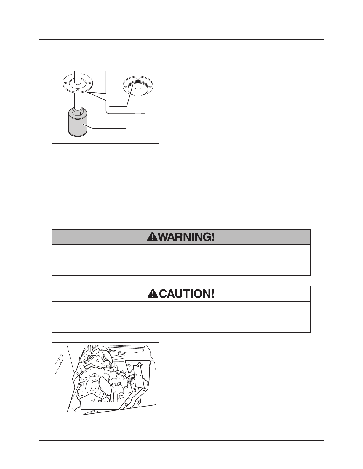
-49-
Maintenance 5
Transmission Oil
• Always park the machine on a level surface and block the tracks with chocks
when working under the machine.
11. Coat O-ring with hydraulic fluid evenly and
insert suction lter mount in tank. Make sure
to insert it straight so that O-ring does not
get out of the groove. Fasten the suction
lter mount with bolts.
12. Open filler cap and fill fluid. Put filler cap
back in place.
13. Undo safety prop. Lower bucket.
14. Start the engine and engage the clutch to
circulate the uid. Watch for leaks.
15. Lift bucket and hold bucket with safety prop.
Inspect uid level.
16. Install tank cover plates 1 and 2. (Page 40)
17. Undo safety prop. Lower bucket.
3570M-0507-180E
Suction Filter
O-ring
1. Park the machine on a level ground.
2. Remove oor panel.
3. Remove ller cap and inspection plug. Pour
oil into filler until oil flows out of inspection
plug.
4. Visually inspect the condition of oil. If dirty,
change it.
3683M-0507-060E
Inspection Plug
Filler Cap
Inspecting
• Dispose of the drained oil properly, according to the national and local regula-
tions.
Page 59
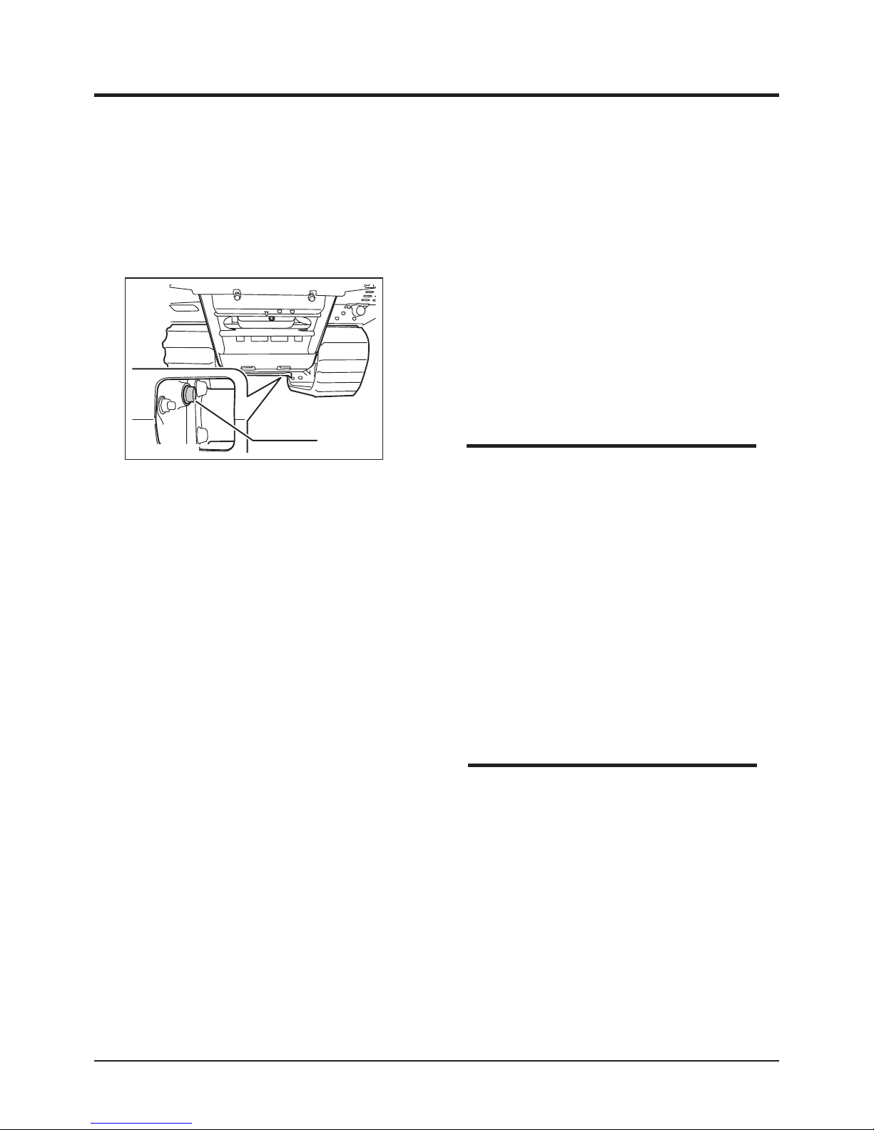
Maintenance
-50-
5
5. Wipe excess oil around inspection hole.
Clean inspection plug and filler cap. Put
inspection plug and filler cap back in place
and tighten them securely.
• Oil Capacity: 3.3L
• Oil to Use: Gear Oil, API rating GL-4 or 5,
SAE index #80.
1. Have an appropriate oil drain pan ready.
2. Remove drain plug to drain oil.
3. Clean drain plug and seal washer. Put drain
plug back in place and tighten it securely.
Watch for leaks.
3683M-0507-070E
Drain Plug
Draining
NOTE
Filling
1. Remove ller cap and inspection plug.
2. Fill oil slowly until oil flow out of inspection
hole.
3. Wipe around inspection hole.
4. Clean inspection plug and seal washer. Put
inspection plug back in place and tighten it
securely. Watch for leaks.
5. Put ller cap back in place.
6. Install oor panel.
• Removing ller cap helps drain oil.
NOTE
Page 60
-51-
Maintenance 5
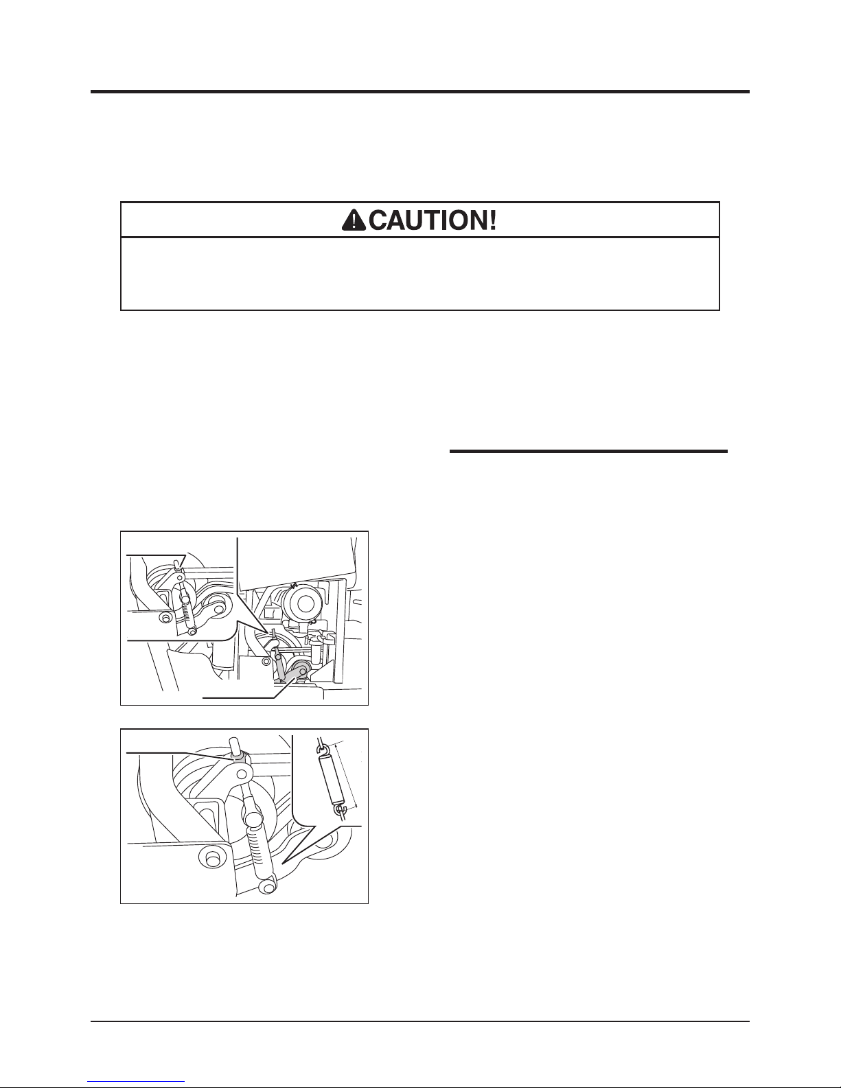
Drive Belts
1. Open engine cover.
2. Visually inspect belt s. Replace bel t if
damaged.
Inspecting
3683M-0507-090E
Lock Nuts
130-132mm
• Adj u s t be l t tens i on pr o p erly. I nproperl y tensi o n ed be l ts ma y reduc e
performance and its service life.
1. Open engine cover.
2. Loosen lock nut.
Adjusting
3683M-0507-080E
Tension Arm
Lock Nuts
• Contact your CANYCOM representative
when belt needs to be replaced.
NOTE
3. Adjust lock nut so that the inside dimension
between spring hooks is between 130 and
132 mm.
4. Close engine cover.
Page 61
Maintenance
-52-
5
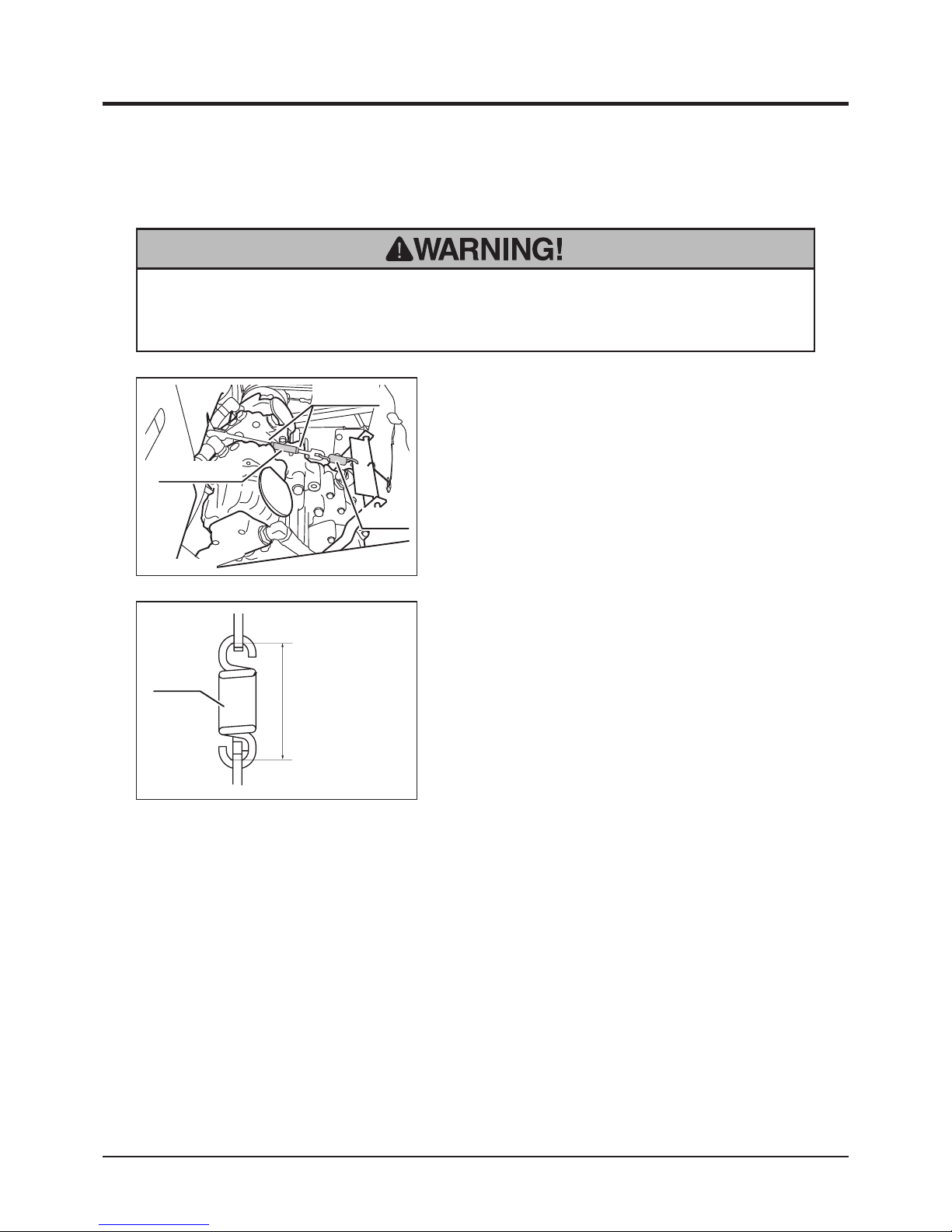
• Always keep brake adjusted for maximum performance. Improperly adjusted
brakes may result in property damage, serious injury, or death.
Parking Brake
3683M-0507-100E
Lock Nuts
Turnbuckle
Spring
1. Make certain steering levers are in the
neutral position.
2. Depress parking brake pedal and lock it.
3. Remove oor panel.
4. Loosen lock nuts on brake linkage.
Inspecting/Adjusting
5. Adjust turmbuckle so that the distance
between spring hooks is between 84 and
85mm.
6. Tighten lock nuts securely.
7. Install oor panel.
3683M-0507-110E
Spring
84 - 85mm
Page 62
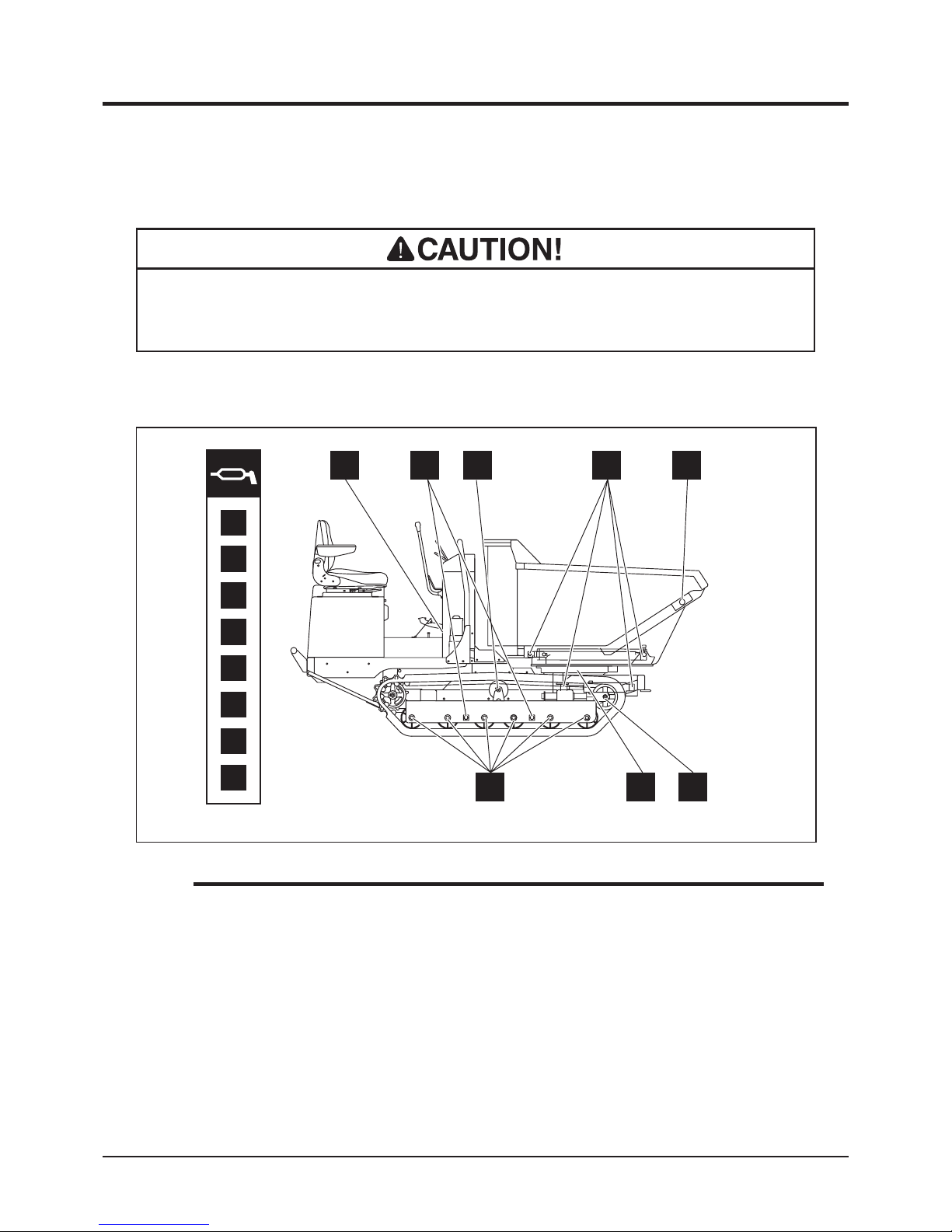
-53-
Maintenance 5
Greasing
• Follow the maintenance schedule to grease the machine. Lack of greasing may
result in rust, excessive wear or seizure.
1
2
3
4
5
6
7
8
3683M-0507-120E
Greasing
Points
5
4
7
6
321
8
1. Grease greasing points as shown below.
• Grease to use: Chassis Grease
• When using a manual grease gun, pump 5-6 times. When the handle of the gun
becomes heavy, stop pumping immediately.
• When using a pneumatic grease gun, pump it for a few seconds.
NOTE
Page 63
Maintenance
-54-
5
Electrical System
Battery
• Explosion hazard. Keep open ame or spark away from battery. Hydrogen gas
generated during charging is extremely explosive.
• Battery fluid (diluted sulfic acid) is corrosive and causes severe burns. Be
extremeley cautious when handling battery fluid. If battery fluid is spilt on
clothes, immediately rinse with plenty of water. If spilt on skin or in an eye,
immediately rinse with plenty of water and promptly consult a physician.
• Never charge battery when the fluid level is below the lower limit. Charging
battery with insufcient uid may shorten battery life or cause an explosion.
• Never ll battery uid beyond the upper limit. Battery uid may spill and cause
damage to the machine or personal injury.
• Always disconnect the negative (-) terminal rst, and connect the positive (+)
terminal rst. Disconnecting or connecting in the opposite order may cause a
short circuit.
• When installing the battery, make certain to connect the positive (+) and
negative (-) terminals to their respective original positions. Avoid contact
between terminals and other surrounding parts.
• Always stop the engine and turn the main switch to [ (OFF)] position, and
disconnect the negative (-) terminal of battery when servicing the electrical
system.
Page 64
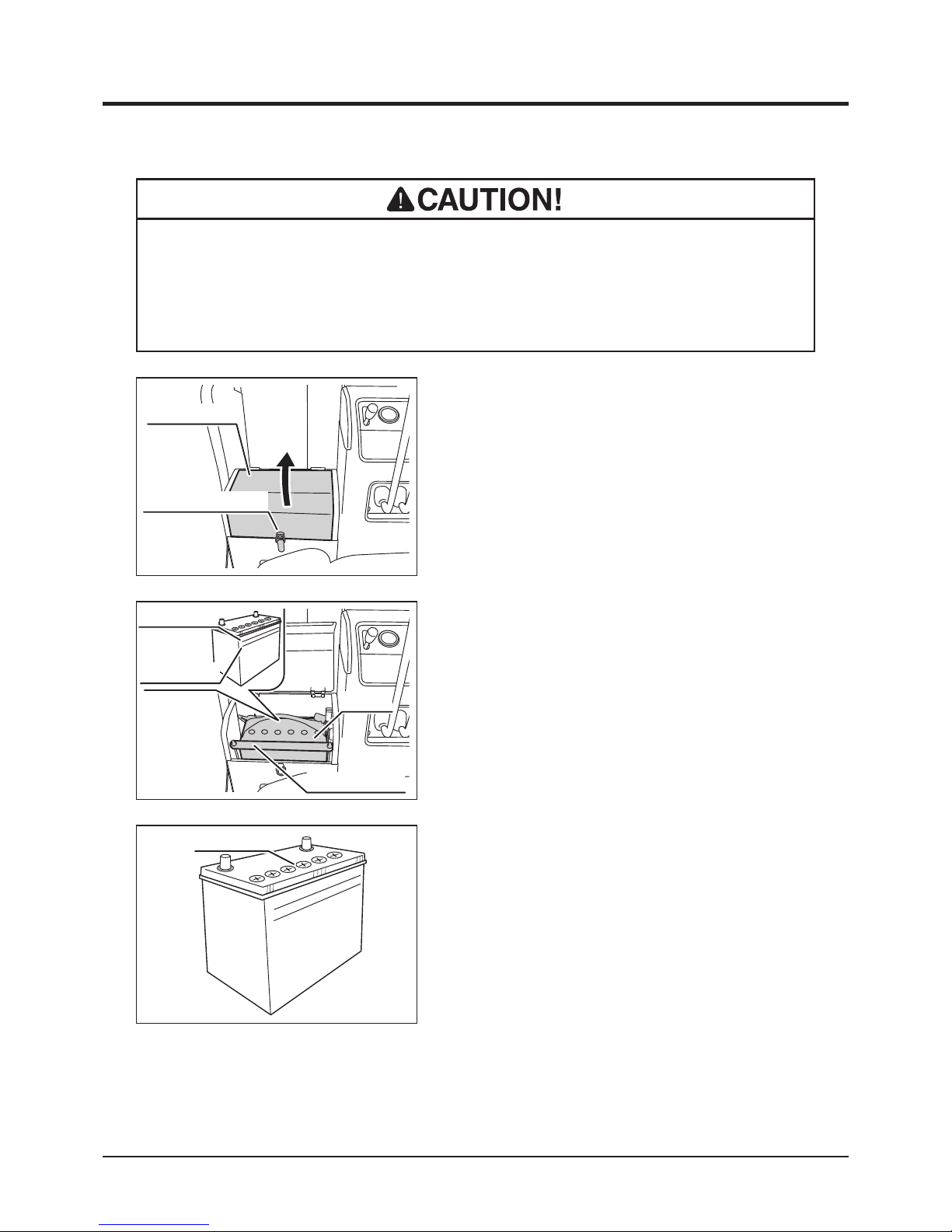
-55-
Maintenance 5
3. Visually inspect that battery fluid level is
between the "Upper Level" and "Lower
Level" lines. If the fluid level is below the
"Lower Level," ll.
UPPER LEVEL
LOWER LEVEL
Filler Plugs
3570M-0509-020E
1. Park the machine on level ground.
2. Unlatch battery cover latch and open battery
cover.
Inspecting
3683M-0508-010E
Battery Cover
Battery Cover Latch
• Always remove battery from the machine before charging. Failure to do so may
cause damage to the electrical components and wiring.
• Follow the battery charger user's manual when charging.
Filling
UPPER LEVEL
LOWER LEVEL
3683M-0508-020E
Battery
Battery Bracket
Upper Level
Lower Level
4. Remove battery bracket and battery from
the machine.
5. Open filler plugs and add distilled water to
battery evenly until uid level is between the
"Upper Level" and "Lower Level" lines.
6. Put ller plugs back in place.
7. Install battery.
8. Close battery cover and latch it.
Page 65
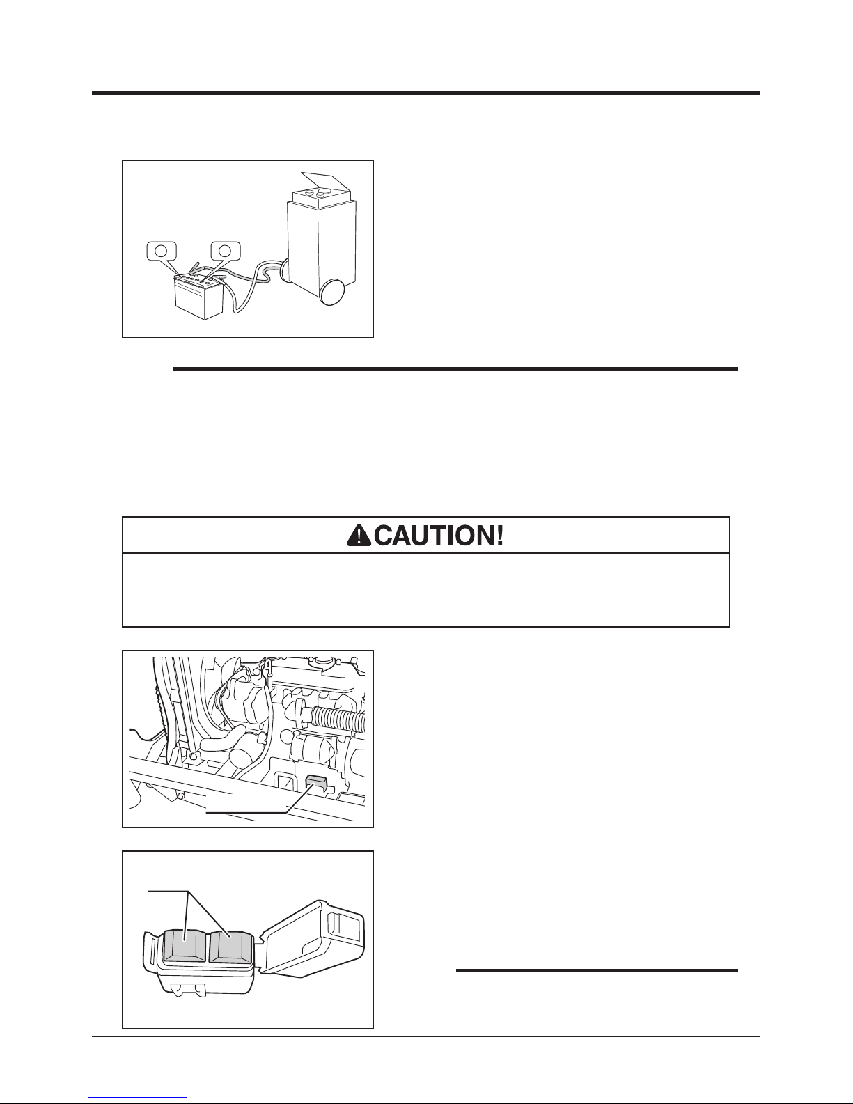
Maintenance
-56-
5
Fuses
1. Open engine cover.
2. Open the lid of fuse housing.
• If a fuse blows, investigate the cause before replacing. Always replace a fuse
with the one of the correct rating.
• Rapid charging is only an emergency measure. This method uses a large amount of
current to compensate the lost charge in a short time. However, the battery needs
to be fully charged in the ordinary method for a longer service life.
NOTE
3683M-0508-030E
Fuse Housing
1. Remove battery from the machine.
2. Remove all ller plugs.
3. Foll ow the i nstruct ions i n the ba tte r y
char g er user 's manu a l t o c harge the
battery.
4. When battery is fully charged, put ller plugs
back in place and install battery.
Charging
UPPER LEVEL
LOWER LEVEL
‑
+
+ ‑
3570M-0509-030E
3683M-0508-040E
Fuses
3. Locate the blown fuse and replace it with a
new one of the correct rating.
4. Put the lid back in place.
5. Close engine cover.
• Replacement Fuse: 40A (2pcs.)
NOTE
Page 66
-57-
Maintenance 5
After Normal Use
1. Clean the machine; wash off dirt, mud, and other foreign matter after use.
2. If the machine is to be left outside, cover the machine with protective, water-proof
covering after the machine is cooled off.
• Do not wash the engine, control panel, electrical parts, or tank caps with air
breather with running water; water may enter inside and cause rust or damage.
• Clean the machine after use; leaving dirt or foreign objects may cause damage.
• Do not attempt to move the machine when it becomes inoperable due to
freezing.
1. Clean the machine; wash off dirt, mud, and other foreign matter after use.
2. Park the machine on a paved or rm, dry surface.
3. If the machine is to be left outside, cover the machine with protective, water-proof
covering after it is cooled off.
After Use Care
After Cold Weather Use
Page 67
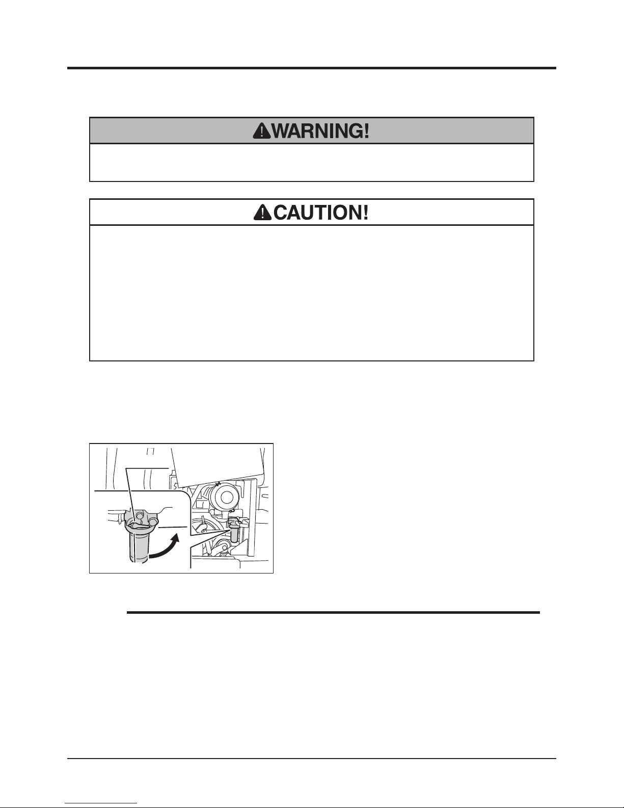
Maintenance
-58-
5
Storage
1. Follow the instructions in Parking (page 28) to park the machine.
2. Clean dirt off of the machine.
3. Change engine oil (page 41).
• Do not wash the engine or control panel with running water; water may enter
inside and cause rust or damage.
• Clean the machine before storage; leaving dirt or foreign objects may cause
rust or damage.
• Do not store the machine in a humid, dusty, or hot place.
• Fire hazard; do not store the machine where there is a possiblity of ignition.
• Battery dischages even when it is not in use. A battery may hold charge for a few
months, but it is a good practice to charge battery before it goes at; it will extend
the battery life.
• Refer to the Operation Manual for the engine, for detailed instructions on preparing
the engine for storage.
• Do not forget to turn the fuel cock to "ON" position when starting the machine.
NOTE
3683M-0509-010E
Off
On
Fuel Cock
4. Clean the air cleaner (page 43).
5. Open engine cover and turn fuel cock to
"OFF" position. Close engine cover.
6. Remove battery from the machine. Service
battery (page 54).
7. Cover the machine with protective, waterproof covering after the machine is cooled
off.
Page 68
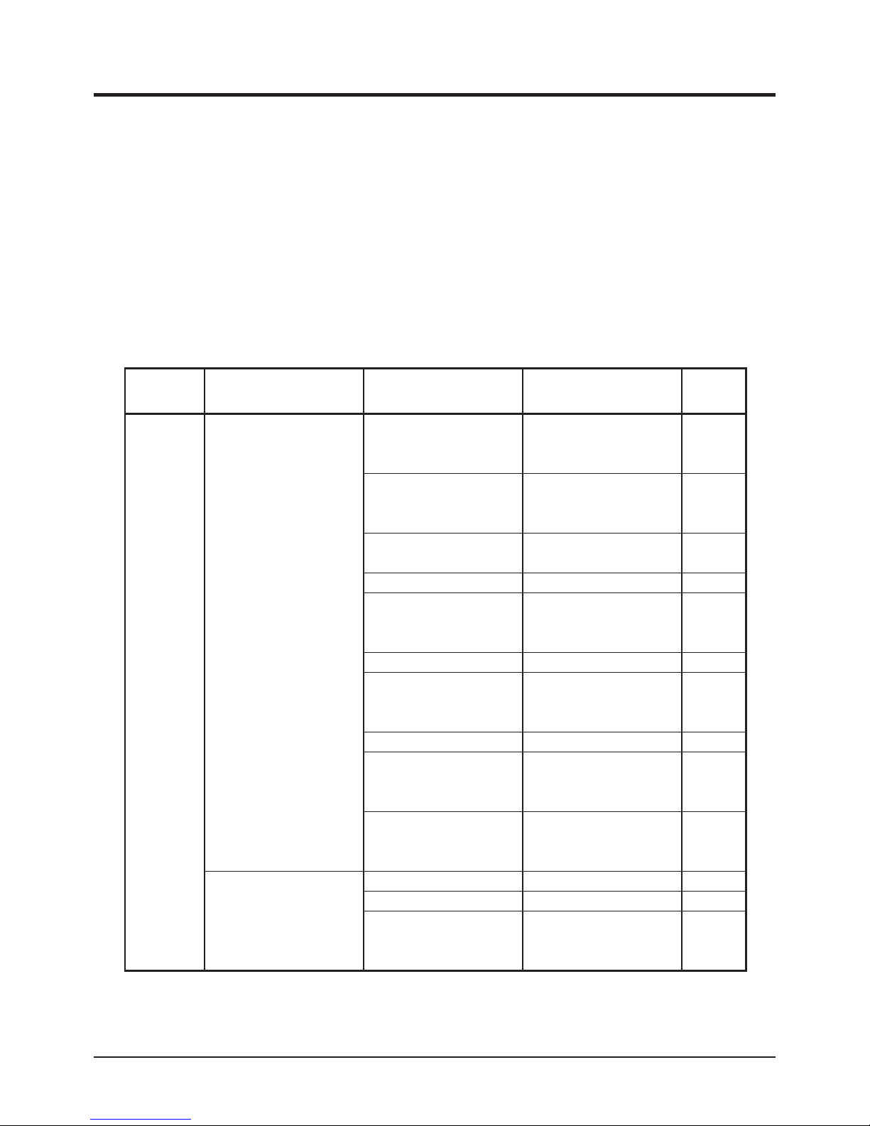
-59-
Troubleshooting
6
Troubleshooting
• If any malfunction or abnormal condition is found, immediately stop using the
machine and take an appropriate measure according to the Troubleshooting chart
below. If the malfunction or abnormal condition is not listed in the chart, or the
suggested measure does not solve the problem, consult with your CANYCOM
representative.
• Some corr ective measur es l isted below requ ire special knowledge and/or
equipment. Please contact your CANYCOM representative in such a case.
Area Malfunction Possible Cause Corrective Measure Ref.
Engine
Engine does not start, or
is difcult to start.
Parking brake lever
is angaged (safety
mechanism is on).
→Disengage parking
brake.
Page 20
Battery is discharged. →Add battery uid.
→Charge Battery.
→Replace battery.
Page 54
Battery cable is
disconnected.
→Connect battery cable.
Blown fuse. →Replace fuse. Page 56
Bad connection
orbreakage in the wiring.
→Please contact
your CANYCOM
representative.
Out of fuel. →Fill fuel. Page 15
Air is in fuel. →Please contact
your CANYCOM
representative.
Insufcient or wrong oil. →Fill or change oil Page 41
Contamination in fuel
system.
→Please contact
your CANYCOM
representative.
Other (other than the
above).
→Please contact
your CANYCOM
representative.
Engine stalls.
Out of fuel. →Fill fuel Page 15
Engine is cold. →Warm up engine.
Choke lever is in [Close]
position.
→Please contact
your CANYCOM
representative.
Page 69
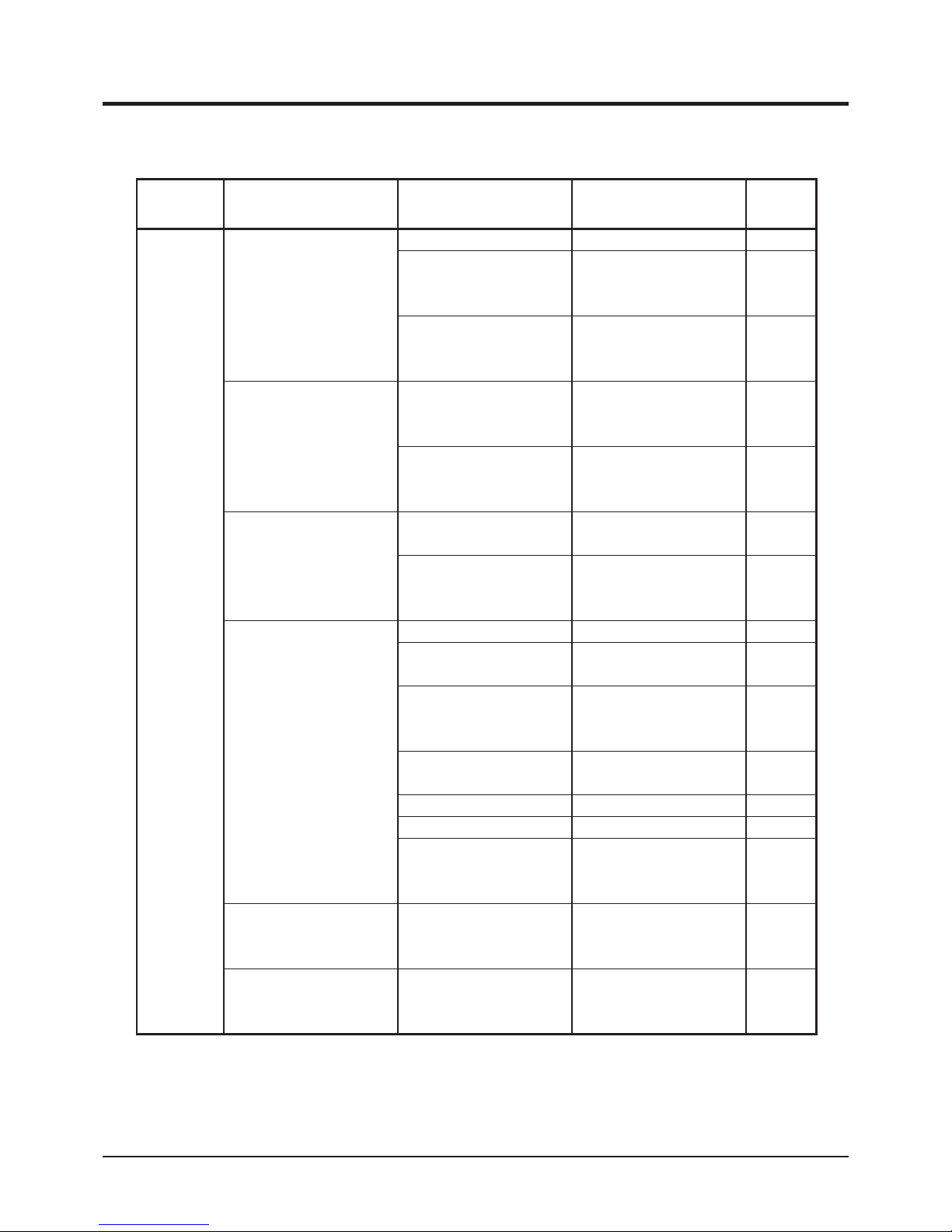
Troubleshooting
-60-
6
Area Malfunction Possible Cause Corrective Measure Ref.
Engine
Engine stops abruptly.
Out of fuel. →Fill fuel. Page 15
Piston seizure due to
insufcient or bad oil.
→Please contact
your CANYCOM
representative.
Other (other than the
above).
→Please contact
your CANYCOM
representative.
Engine does not stop.
Electrical malfunction. →Please contact
your CANYCOM
representative.
Other (other than the
above).
→Please contact
your CANYCOM
representative.
Idling is not stable
Insufcient intake air
(clogged air cleaner) .
→Clean or replace air
cleaner element.
Page 43
Other (other than the
above).
→Please contact
your CANYCOM
representative.
Poor power or
acceleration
Bad fuel. →Change fuel.
Wrong oil (improper
viscosity).
→Clean or replace air
cleaner element.
Page 41
Accelerator (throttle) is
not properly adjusted.
→Please contact
your CANYCOM
representative.
Insufcient intake air
(clogged air cleaner) .
→Clean or replace air
cleaner element.
Page 43
Excessive load. →Reduce load.
Loose drive belt. →Adjust. Page 51
Other (other than the
above).
→Please contact
your CANYCOM
representative.
Irregular noise or
vibration from or around
engine.
→Please contact
your CANYCOM
representative.
Excessive oil
consumption.
→Please contact
your CANYCOM
representative.
Page 70
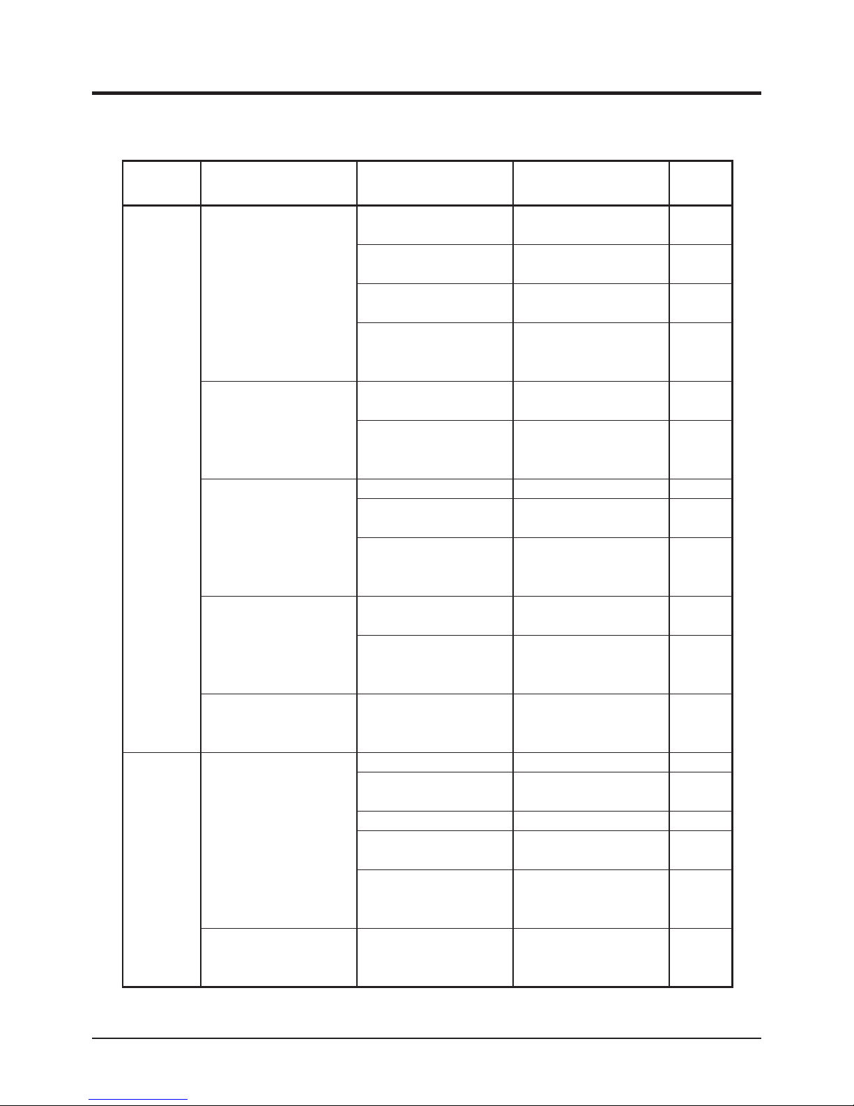
-61-
Troubleshooting
6
Area Malfunction Possible Cause Corrective Measure Ref.
Engine
Engine overheats.
Insufcient amount of
engine oil.
→Fill oil. Page 41
Insufcient amount of
engine coolant.
→Fill coolant. Page 41
Radiator or cooling fan is
clogged or blocked.
→Clean.
Other (other than the
above).
→Please contact
your CANYCOM
representative.
Excessive fuel
consumption.
Clogged air cleaner. →Clean or replace air
cleaner element.
Page 43
Other (other than the
above).
→Please contact
your CANYCOM
representative.
Black smoke comes out
of exhaust.
Bad fuel. →Change fuel.
Clogged air cleaner. →Clean or replace air
cleaner element.
Page 43
Other (other than the
above).
→Please contact
your CANYCOM
representative.
Black smoke comes out
of exhaust.
Engine oil level is too
high.
→Adjust oil level.
Other (other than the
above).
→Please contact
your CANYCOM
representative.
Accelerator lever is
catching.
Faulty wire, rod, or
linkage.
→Please contact
your CANYCOM
representative.
Drive Train
Machine does not move
(forward, backward,
turning) when steering
levers are in the
corresponding position.
Clutch is not engaged. →Engage clutch. Page 23
Parking brake is applied. →Release parking
brake.
Page 20
Excessive load. →Reduce load.
Insufcient or
deteriorated HST uid.
→Add or change uid. Page 47
Other (other than the
above).
→Please contact
your CANYCOM
representative.
Irregular noise or heat is
observed at or around
track.
→Please contact
your CANYCOM
representative.
Page 71

Troubleshooting
-62-
6
Area Malfunction Possible Cause Corrective Measure Ref.
Brake
Brake does not work
well.
Not properly adjusted. →Adjust. Page 52
Brake is wet with water. →Apply brake a few
times to dry.
Other (other than the
above).
→Please contact
your CANYCOM
representative.
Track
Track does not move
smoothly.
Not properly adjusted. →Adjust. Page 46
Other (other than the
above).
→Please contact
your CANYCOM
representative.
Safety
Devices
Lamp does not light.
Blown bulb. →Replace.
Blown fuse. →Replace. Page 56
Other (other than the
above).
→Please contact
your CANYCOM
representative.
Horn does not work.
Blown fuse. →Replace. Page 56
Other (other than the
above).
→Please contact
your CANYCOM
representative.
Hydraulic
(dump
and turn)
system
Dump or turn does not
work.
Insufcient or
deteriorated hydraulic
uid.
→Add or change uid. Page 47
Other (other than the
above).
→Please contact
your CANYCOM
representative.
Page 72

-63-
Transporting
7
• Park the transporter (truck) on a level ground. Always use chocks to secure
wheels.
• Do not allow bystandars to come close to the machine or the transporter when
loading or unloading the machine.
• Use only the loading ramps with sufcient strength (to withstand the combined
weight of the machine and the operator), width (more than 1.2 times the width
of the track), and length (more than 4 times the height of the loading deck of the
transporter), and have anti-slip ramp surfaces.
• Secure the hooks of the loading ramps rmly and ush with the loading deck.
• Move slowly backward when loading onto, and move slowly forward when
unloading off of the transporter. Pay special care when going over the joint
between the loading deck and the ramps; the machine may tip.
• Do not turn on the loading ramps. The machine may fall.
• Tie down the machine securely. Make sure the machine does not move around
on the loading deck.
Hauling
Loading and Unloading
Page 73
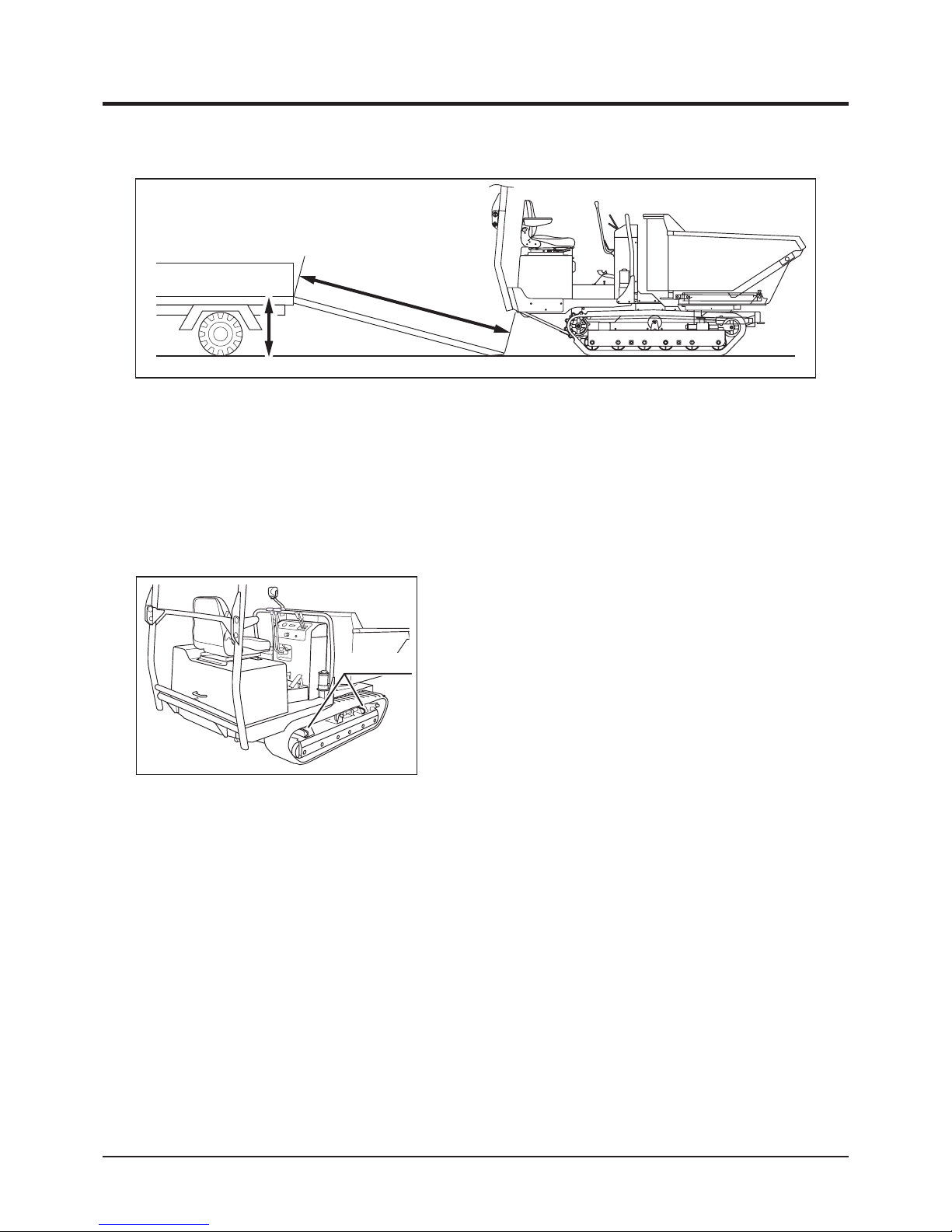
Transporting
-64-
7
3683M-0701-010US
More than 4 times
the height
Height
Loading to the Transporter
1. Park the transporter. Secure the wheels with chocks.
2. Place the loading ramps. Secure the hooks of the ramps firmly and flush with the
loading deck.
3. Drive the machine slowly backward onto the loading deck.
4. Park the machine according to the instructions in "Parking" (Page 28).
5. Tie the machine at lift hooks with rope or tiedown belts and secure it onto the loading
deck of the transporter securely.
Unloading from the Transporter
1. Park the transporter. Secure the wheels with chocks.
2. Undo rope or tie-downs that secure the machine.
3. Place the loading ramps. Secure the hooks of the amps rmly and ush with the loading
deck.
4. Drive the machine slowly forward from the loading deck to the ground.
3683M-0701-020US
Lift Hooks
Page 74
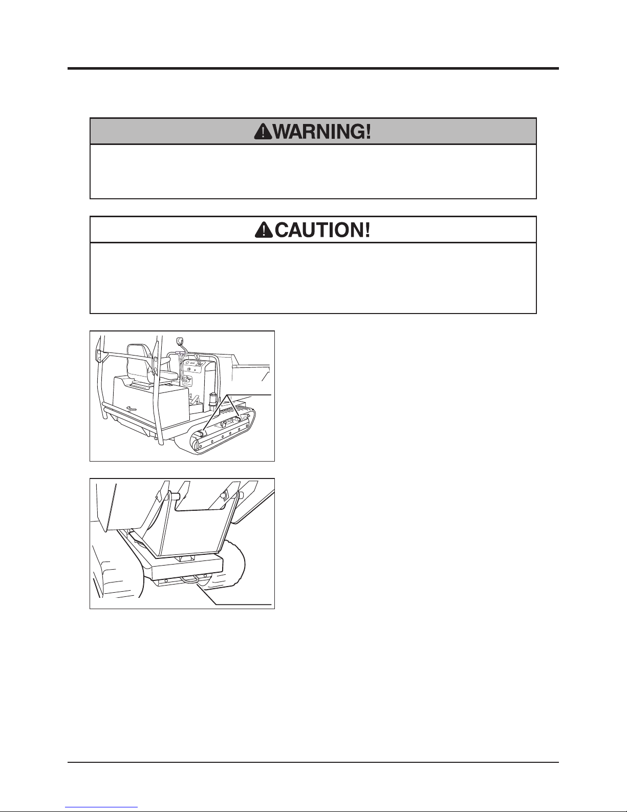
-65-
Transporting
7
• Always unload the machine before hoisting.
• Do not use the wire rope when hoisting. It will damage tracks.
Hoisting and Towing
1. Attach hoisting slings to 4 lift hooks located
on the corners of the machine. Hoist the
center of the slings.
3683M-0701-020US
Lift Hooks
• Use hoisting sling of sufficient strength. Always use the slings of the same
length when more than one is used.
Hoisting
1. Hook the towing belt to towing hook in the
front of the machine.
3683M-0701-030E
Towing Hook
Towing
Page 75
Model
Engine
LpA
LwA
Type Type Speed rpm Left Right
S160
Kubota
D1105-E3B
2400 rpm 84.6 dB (A) 84.5 dB (A) 101 dB (A)
NOISE LEVEL evaluated based on factory standard.
NOISE LEVEL
Model
Engine
Rated revolution
Vibration
Steering lever Seat
S160 2400 rpm 2.6 m/s
2
5.0 m/s
2
VIBRATION evaluated based on factory standard.
VIBRATION
 Loading...