

CanyCom CMX 227, CMX 186, CM185, CMX CM226 Operator's Manual

Ride-on Brushcutter
CMX 227/ CM226/ CMX186/ CM185
Operator's Manual
5321 5311 003
Read this manual completely before operating or maintaining this machine.
Failure to follow safety precautions could result in serious injury or death.
Keep this manual for future reference by you and by all those who operate
and maintain this machine.
Original Instructions
(in English)
5335 5311 003

http://www.canycom.co.jp/
90-1 Fukumasu, Yoshii-machi,
Ukiha-shi, Fukuoka, Japan 839-1396
Sales Headquarters (International) TEL +81-(0)943-75-2195
FAX +81-(0)943-75-4396
Authorized Dealer
All rights reserved. Unauthorized use or reproduction of this material is prohibited.
Notice to Users and Maintenance Personnel
Thank you for purchasing this machine.
This manual provides information needed for safe and effective use of this machine to those
who operate or maintain machine. Make sure to read and understand the manual thoroughly
before operating this product. Also make sure to read the separate operator's manual for
engine.
• This machine can be very dangerous if the safety precautions in this manual
and on the labels attached to this machine are not followed. Read and
understand this manual and safety labels on machine thoroughly before using
this machine. Always follow the instructions and safety precautions, or serious
injury or death could result.
• This machine should only be used for its intended purpose: cutting grass and
bushes. Any other use could be dangerous.
• This machine may not be operated on public road or what is considered to
be public road. It is the sole responsibility of the operator to consult the local
regulations.
• Do not modify this machine, or do not operate this machine with the safety
covers removed or open. A serious accident could result.
• Store this manual in a safe, accessible place for easy reference.

Notice to Owner
• Be sure that everyone who uses this machine, including those who rent or
lease this machine, receives a copy of this Operator's Manual and understands
the importance of reading and following the information in this manual.
Warning Terms Used in this Manual
In this manual, the following four warning terms are used to signal the four levels of hazard (or
seriousness of possible accidents). Read and understand what they mean and always follow
the instructions in this manual.
Warning Term Denition
Indicates an imminently hazardous situation which will result
NOTE
in death or serious injury if the user does not follow the
procedures or the instructions.
Indicates a potentially hazardous situation which could result
in death or serious injury if the user does not follow the
procedures or the instructions.
Indicates a potentially hazardous situation which could result
in minor to moderate injury or damage to the machine if the
user does not follow the procedures or the instructions.
Indicates important information which needs particular
attention.
Warranty and After-Sales Service
Warranty
CHIKUSUI CANYCOM, INC. guarantees this product, based on the terms of warranty.
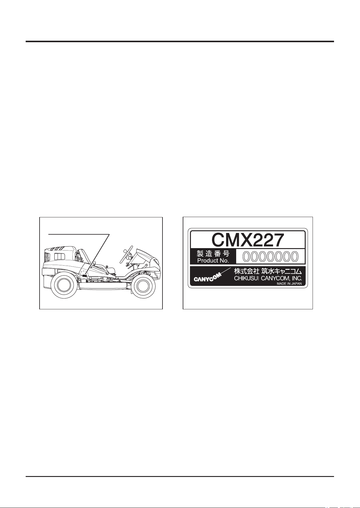
After-Sales Service
Consult your local CANYCOM dealer or our company’s sales department regarding service
orders or any questions or problems that may arise when using this machine. Please make
sure to have the product name, serial number, and the make and type of engine handy at
the time of contact. The model and serial number can be found on the model label as shown
below, and the make and type of the engine can be found in Chapter 3 "Specications" of
this manual (Page15).
Location of Model Label
Location of Model Label
5332M-0005-010E
Model Label
5335M‑0005‑020
Availability of Spare Parts
The replacement or repair parts for this product shall remain available for seven years after
the production of this type of machine is discontinued.

Contents
1. Safety 1
Safety Labels . . . . . . . . . . . . . . . . . . . . . . . . . . . . . . . . . . . 1
Safety Mechanisms . . . . . . . . . . . . . . . . . . . . . . . . . . . . . . 3
Safety Precautions . . . . . . . . . . . . . . . . . . . . . . . . . . . . . . . 4
Training . . . . . . . . . . . . . . . . . . . . . . . . . . . . . . . . . . . . . . . . . . . . . . . . . . . . . . . 4
Preparation . . . . . . . . . . . . . . . . . . . . . . . . . . . . . . . . . . . . . . . . . . . . . . . . . . . . 5
Operation . . . . . . . . . . . . . . . . . . . . . . . . . . . . . . . . . . . . . . . . . . . . . . . . . . . . . . 6
Servicing . . . . . . . . . . . . . . . . . . . . . . . . . . . . . . . . . . . . . . . . . . . . . . . . . . . . . 10
2. Controls and Components 11
Name and Function of Controls . . . . . . . . . . . . . . . . . . . 11
3. Specications 15
Product Specications . . . . . . . . . . . . . . . . . . . . . . . . . . 15
Contents of Tool Bag . . . . . . . . . . . . . . . . . . . . . . . . . . . 16
4. Operation 17
Preparation . . . . . . . . . . . . . . . . . . . . . . . . . . . . . . . . . . . . 17
Pre-start up Inspection . . . . . . . . . . . . . . . . . . . . . . . . . . . . . . . . . . . . . . . . . . 17
Checking and Filling Fuel . . . . . . . . . . . . . . . . . . . . . . . . . . . . . . . . . . . . . . . 17
Adjusting Steering Wheel . . . . . . . . . . . . . . . . . . . . . . . . . . . . . . . . . . . . . . . 18
Adjusting Seating Position . . . . . . . . . . . . . . . . . . . . . . . . . . . . . . . . . . . . . . 20
Adjusting Drive Pedal . . . . . . . . . . . . . . . . . . . . . . . . . . . . . . . . . . . . . . . . . . . 22

Driving . . . . . . . . . . . . . . . . . . . . . . . . . . . . . . . . . . . . . . . . 22
Starting . . . . . . . . . . . . . . . . . . . . . . . . . . . . . . . . . . . . . . . . . . . . . . . . . . . . . . 22
Driving . . . . . . . . . . . . . . . . . . . . . . . . . . . . . . . . . . . . . . . . . . . . . . . . . . . . . . . 26
Stopping . . . . . . . . . . . . . . . . . . . . . . . . . . . . . . . . . . . . . . . . . . . . . . . . . . . . . 28
Shifting . . . . . . . . . . . . . . . . . . . . . . . . . . . . . . . . . . . . . . . . . . . . . . . . . . . . . . . 30
Shifting Between 2WD and AWD (CMX227 / CMX186) . . . . . . . . . . . . . . . . . 30
Locking Differential . . . . . . . . . . . . . . . . . . . . . . . . . . . . . . . . . . . . . . . . . . . . 31
Parking . . . . . . . . . . . . . . . . . . . . . . . . . . . . . . . . . . . . . . . . . . . . . . . . . . . . . . . 32
Working . . . . . . . . . . . . . . . . . . . . . . . . . . . . . . . . . . . . . . . 34
Inspecting Cutting Blade . . . . . . . . . . . . . . . . . . . . . . . . . . . . . . . . . . . . . . . . 34
Adjusting Cutting Height . . . . . . . . . . . . . . . . . . . . . . . . . . . . . . . . . . . . . . . . 34
Cutting . . . . . . . . . . . . . . . . . . . . . . . . . . . . . . . . . . . . . . . . . . . . . . . . . . . . . . . 35
Adjusting Cutting Blade Shield . . . . . . . . . . . . . . . . . . . . . . . . . . . . . . . . . . . 40
5. Maintenance 41
Maintenance Schedule . . . . . . . . . . . . . . . . . . . . . . . . . . 41
Engine . . . . . . . . . . . . . . . . . . . . . . . . . . . . . . . . . . . . . . . . . . . . . . . . . . . . . . . 41
Chassis . . . . . . . . . . . . . . . . . . . . . . . . . . . . . . . . . . . . . . . . . . . . . . . . . . . . . . 42
List of Fluids and Lubricants . . . . . . . . . . . . . . . . . . . . . 45
Greasing Points . . . . . . . . . . . . . . . . . . . . . . . . . . . . . . . . 46
Greasing Points (CMX227 / CMX186) . . . . . . . . . . . . . . . . . . . . . . . . . . . . . . 46
Greasing Points (CM226 / CM185) . . . . . . . . . . . . . . . . . . . . . . . . . . . . . . . . . 47
List of Consumables and Spares . . . . . . . . . . . . . . . . . . 48
Removing and Installing Body Panels . . . . . . . . . . . . . . 50
Front Cover . . . . . . . . . . . . . . . . . . . . . . . . . . . . . . . . . . . . . . . . . . . . . . . . . . . 50
Head Lamp . . . . . . . . . . . . . . . . . . . . . . . . . . . . . . . . . . . . . . . . . . . . . . . . . . . . 51
Engine Hood . . . . . . . . . . . . . . . . . . . . . . . . . . . . . . . . . . . . . . . . . . . . . . . . . . 52
Lower Rear Cover . . . . . . . . . . . . . . . . . . . . . . . . . . . . . . . . . . . . . . . . . . . . . . 52
Step . . . . . . . . . . . . . . . . . . . . . . . . . . . . . . . . . . . . . . . . . . . . . . . . . . . . . . . . . 52
Seat Bracket . . . . . . . . . . . . . . . . . . . . . . . . . . . . . . . . . . . . . . . . . . . . . . . . . . 53
Cutting Blade Shield . . . . . . . . . . . . . . . . . . . . . . . . . . . . . . . . . . . . . . . . . . . . 53

Engine . . . . . . . . . . . . . . . . . . . . . . . . . . . . . . . . . . . . . . . . 55
Engine Oil . . . . . . . . . . . . . . . . . . . . . . . . . . . . . . . . . . . . . . . . . . . . . . . . . . . . 55
Oil Filter Cartridge . . . . . . . . . . . . . . . . . . . . . . . . . . . . . . . . . . . . . . . . . . . . . 57
Air Cleaner . . . . . . . . . . . . . . . . . . . . . . . . . . . . . . . . . . . . . . . . . . . . . . . . . . . . 57
Spark Plugs . . . . . . . . . . . . . . . . . . . . . . . . . . . . . . . . . . . . . . . . . . . . . . . . . . . 58
Drive Train . . . . . . . . . . . . . . . . . . . . . . . . . . . . . . . . . . . . . 59
Tires . . . . . . . . . . . . . . . . . . . . . . . . . . . . . . . . . . . . . . . . . . . . . . . . . . . . . . . . . 59
Transmission Oil . . . . . . . . . . . . . . . . . . . . . . . . . . . . . . . . . . . . . . . . . . . . . . . 60
Front Axle Oil (CMX227 / CMX186) . . . . . . . . . . . . . . . . . . . . . . . . . . . . . . . . 60
HST (Hydrostatic Transmission) Fluid . . . . . . . . . . . . . . . . . . . . . . . . . . . . . 61
Drive Belt . . . . . . . . . . . . . . . . . . . . . . . . . . . . . . . . . . . . . . . . . . . . . . . . . . . . . 63
Parking Brake . . . . . . . . . . . . . . . . . . . . . . . . . . . . . . . . . . . . . . . . . . . . . . . . . 64
Cutting System . . . . . . . . . . . . . . . . . . . . . . . . . . . . . . . . . 65
Cutting Blades . . . . . . . . . . . . . . . . . . . . . . . . . . . . . . . . . . . . . . . . . . . . . . . . . 65
Cutting Rotary Drive Belt and Cutting Rotary Brake . . . . . . . . . . . . . . . . . . 68
Electrical System . . . . . . . . . . . . . . . . . . . . . . . . . . . . . . . 71
Battery . . . . . . . . . . . . . . . . . . . . . . . . . . . . . . . . . . . . . . . . . . . . . . . . . . . . . . . 71
Fuses . . . . . . . . . . . . . . . . . . . . . . . . . . . . . . . . . . . . . . . . . . . . . . . . . . . . . . . . 73
Light Bulbs . . . . . . . . . . . . . . . . . . . . . . . . . . . . . . . . . . . . . . . . . . . . . . . . . . . 73
After Use Care . . . . . . . . . . . . . . . . . . . . . . . . . . . . . . . . . 75
Cutting System . . . . . . . . . . . . . . . . . . . . . . . . . . . . . . . . . . . . . . . . . . . . . . . . 75
After Normal Use. . . . . . . . . . . . . . . . . . . . . . . . . . . . . . . . . . . . . . . . . . . . . . . 76
After Cold Weather Use . . . . . . . . . . . . . . . . . . . . . . . . . . . . . . . . . . . . . . . . . 77
Storage . . . . . . . . . . . . . . . . . . . . . . . . . . . . . . . . . . . . . . . 78
6. Troubleshooting 79
Troubleshooting . . . . . . . . . . . . . . . . . . . . . . . . . . . . . . . . 79

7. Transporting 84
Hauling . . . . . . . . . . . . . . . . . . . . . . . . . . . . . . . . . . . . . . . 84
Loading and Unloading . . . . . . . . . . . . . . . . . . . . . . . . . . . . . . . . . . . . . . . . . 84
Hoisting . . . . . . . . . . . . . . . . . . . . . . . . . . . . . . . . . . . . . . . 85
Warranty
Warranty Certicate is attached at the end of this manual.
* Have the warranty certicate signed after you have received and fully understood
the instructions for handling this machine and received the receipt.
Appendix
• Operator's Manual for the Engine
* Be sure to read and understand it together with this manual .
Safety 1
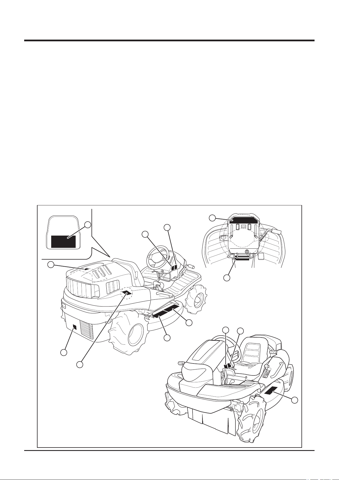
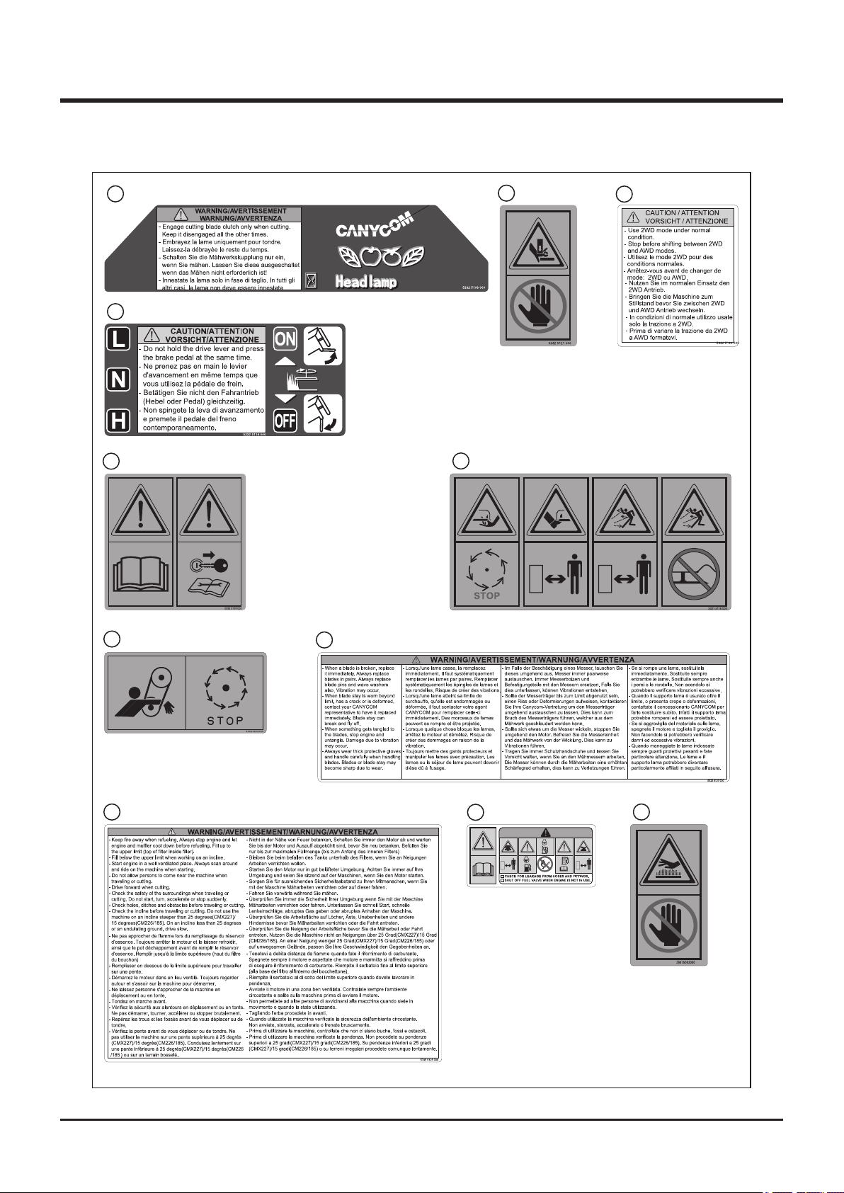
Safety Labels
The safety labels shown on the next page are attached to the machine. See the illustration
below for the location and the illustration on the next page for the content of each label on
the machine.
• Locate all the warning labels attached to this machine. Read and follow the instructions
and precautions in them. Failure to do so could result in serious injury or death to the
operator or bystanders.
• Keep the labels clean and legible. Do not use solvents or gasoline to clean the labels.
• Replace these labels immediately if they have been removed, have fallen off or become
illegible. Use the part number, on the label or shown in this manual, to order a replacement
label from your CANYCOM representative.
10
1
9
3
7
11
(Models with the
Charge-pump only)
CMX227 and
4
CMX186
8
2
6
5
3
5335M-0101-012E
6
-1-
1
1
5332 5109 000
2
5332 5114 000
5
5332 5128 000
Safety
3
5321 5116 000
6
5332 5121 000
4
5332 5122 000
5305 5326 0007
5335 5125 000
9
5332 5127 0008
5332 5127 000
10
11
3667 5063 000
5332M-0101-020
-2-

Safety 1
Safety Mechanisms
This product is equipped with the following safety mechanisms.
Start Interlock Mechanism
Engine can be started only when parking brake is in [ (engaged)] position and cutting
rotary clutch in [OFF] position. This is to prevent unintended movement of machine or cutting
blade when starting engine.
Automatic Blade Stopping Mechanism
Engine stops if operator is not seated while cutting blade is rotating. This is to reduce the
possibility of accident related to moving blade when machine is turned over.
-3-

1
Safety
Safety Precautions
This section contains safety precautions to follow when operating and maintaining the
machine. Read and understand the precautions in this section as well as throughout this
manual and follow them when operating or maintaining the machine. Failure to follow safety
precautions could result in property damage, serious injury or death to the operator or
bystanders.
Training
All operators and mechanics should receive practical instructions from their employer or
renter. Such instructions should cover the following issues:
• It is essential to familiarize yourself with the controls, safety labels and the proper use of
the machine.
• Never allow people unfamiliar with these instructions to operate or service the machine.
Do not let anyone under 18 years of age to operate this machine. Local regulations may
restrict the minimum age for operating the machine. Consult your local authority.
• The operator is responsible for the accidents or hazards caused to other people or their
property.
• This machine has a riding capacity for one person only. Do not carry passengers other
than the operator.
• Observe the weight limit of this machine: 120kg.
• Always keep in mind that care and concentration is required when working with ride-on
machines.
• Loss of control on a slope cannot be regained by the application of the brake. The main
reasons for loss of control are:
→ insufcient grip of tires.
→ excessive speed.
→ misjudging of the ground conditions, especially slopes.
-4-

Safety 1
Preparation
• Fuel is highly ammable. See Checking and Filling Fuel, page 17, for important safety
information on handling fuel.
• Always wear protective footwear, long trousers, hardhat, safety glasses and ear protection
when operating or servicing the machine. Proper clothing will minimize the chance of
injury. Do not operate the equipment if you have long hair, loose clothing, or jewelry; all of
which may get tangled in moving parts. Do not operate the machine barefoot or with open
sandals.
• Prepare beforehand the working rules and procedures such as signaling and trac control
for the work place. Following such rules will reduce the risk of accidents.
• Never handle fuel or grease, service the engine, or recharge the battery in the presence of
re or spark.
• Perform the daily pre-startup inspection (see Preparation, pages 17) before starting the
machine. Repair or replace damaged parts before starting the machine.
-5-

1
Safety
Operation
This machine is intended for cutting grass and bushes. Any other use may pose hazard or
cause damage to the machine.
The stability of the machine is affected by the speed, rate of steering, terrain and the
operator's weight. Always pay close attention to these factors or a loss of control or tip over
could occur, resulting in property damage, serious injury or death.
General Driving
• Do not operate the engine in a conned space where dangerous carbon monoxide fumes
can accumulate.
• Do not touch the engine, mufer or exhaust pipe while the engine is running or soon after
it has stopped. These areas will be very hot and can cause burns.
• Do not operate the machine under the inuence of alcohol or drugs. Do not operate the
machine when you are tired, ill, or not feeling well.
• Always check for obstacles before operating on new terrain. This includes overhead
obstacles such as the branches of a tree.
• Before starting the engine and moving the machine, scan around your surroundings and
make sure all persons and other vehicles are a safe distance away from the machine.
• On a slippery surface, travel slowly and exercise caution to reduce the chance of skidding
or sliding out of control. Never operate on ice.
• Always make certain that there is no obstacle or a person behind the machine when
backing up. After conrming that it is safe to back up, move slowly and avoid sharp turns.
• To reduce the risk of tip over, pay special attention when encountering an obstacle or a
slope, or when braking on a slope or during a turn. See Driving on a Slope on page 8.
• Never attempt to drive over a large obstacle such as rock or fallen tree.
-6-

Safety 1
• Always travel slowly and use extra caution when operating on unfamiliar terrain. Be alert
when traveling on changing terrain.
• Never operate on terrain that you are not comfortable with. Avoid terrain that is so rough,
slippery or loose that you feel like you could tip over.
• Do not operate the machine near the edge of a cliff, an overhang or a slide area. Pay
special attention after heavy rain or earthquake.
• Do not make sudden maneuvers. A sudden start, stop, or turn can make the machine lose
control and could cause a tip over. Be especially cautious when traveling on soft or wet
ground.
• Drive at a safe speed, taking into account the surface gradient, surface conditions and
load.
-7-

1
Safety
Driving on a Slope
• Never use on a slope steeper than 25 degrees for the CMX227 and the CMX186, and
15 degrees for the CM226 and CM185.
• Driving on a slope can be dangerous. It can result in a tip over and cause serious
injury or death. Take the following precautions.
• Always follow proper procedures for driving on a slope as described in this manual.
• Driving on a slope in a wrong manner can cause a loss of control or a vehicle tip over.
Check the terrain carefully before attempting to drive on a slope.
• Never drive on a slope that you are not comfortable with. Avoid a slope that is so rough,
slippery, or loose that you feel like you could tip over.
• When driving up a slope, proceed at a steady rate of speed and throttle position.
• Never move the throttle lever, the drive lever, the drive pedal or the steering wheel
suddenly.
• If the engine stalls or loses traction during a climb and cannot make it to the top of the
slope, do not try to turn the machine around. Carefully back down slowly, straight down the
slope.
• Drive straight up or down slopes. Avoid turning on a slope.
• When going over the top of a slope, go slow; an obstacle, a sharp drop, or another vehicle
or person could be on the other side of the crest.
• Avoid driving the machine across a slope.
• Before driving down a slope, stop and shift auxiliary transmission to [L (low)] position. Drive
slowly. Use the engine speed to help keep the machine speed low.
-8-

Safety 1
Cutting
When conducting cutting operation, take the following precautions.
• Always follow the proper procedures for cutting as described in this manual.
• Shutt off the work site. Post signs to inform of the cutting operation. Close off the site with
rope if necessary to keep people, especially children, off the work site.
• Pay attention to the surrounding area. Rotating cutting blade throws stones, rocks and
debris. This may cause property damage, injury, or death.
• Drive forward when cutting. This best prevents the cutting blades from throwing stones,
rocks, or debris.
• Pay attention to obstacles. This includes overhead obstacles such as the branches of a
tree.
Parking
• Park the machine on a at, level and stable surface. Never park on a slope steeper than
10 degrees. Avoid parking on a slope less than 10 degrees. If parking on a slope less than
10 degrees is absolutely unavoidable, apply the parking brake and block the wheels at the
lower end of the machine.
→ Park the machine facing uphill
→ Do not park sideways on a slope.
• Never park on an instable surface. Do not park near the edge of a cliff.
• Observe all the previous precautions for driving, driving on a slope, loading .
• Whenever you park the machine, apply the parking brake and stop the engine. Remove
the key whenever you leave the machine unattended to prevent unauthorized use or
accidental starting.
• Gasoline is extremely flammable and can be explosive. When parking the machine
indoors, make certain that the building is well ventilated and that the machine is not close
to any source of ame or spark, including appliances with pilot lights.
-9-

1
Safety
Servicing
• Do not service the machine when the engine is running. If it is absolutely necessary to run
the engine while servicing, pay attention to the moving parts.
• Do not operate the engine in a conned space where dangerous carbon monoxide fumes
can accumulate.
• Make sure all hydraulic line connectors are tight and all hydraulic hoses and lines are in
good condition and leak-free.
• Keep your body and hands away from pinhole leaks or nozzles that eject hydraulic
uid under high pressure. Use paper or cardboard, not your hands, to search for leaks.
Hydraulic uid escaping under pressure can have sufcient force to penetrate the skin and
cause serious injury.
• Check all fuel lines on a regular basis for tightness and wear. Tighten or repair them as
needed.
• If the engine must be running to perform a service, keep hands, feet, clothing and any
part of the body away from any moving part, especially the cooling fan and the belts at the
back of the engine.
• Do not touch the engine, mufer, or exhaust pipe while the engine is running or soon after
it has stopped. These areas will be very hot and can cause burns.
• The engine must be shut off before checking or adding oil.
-10-
Controls and Components 2
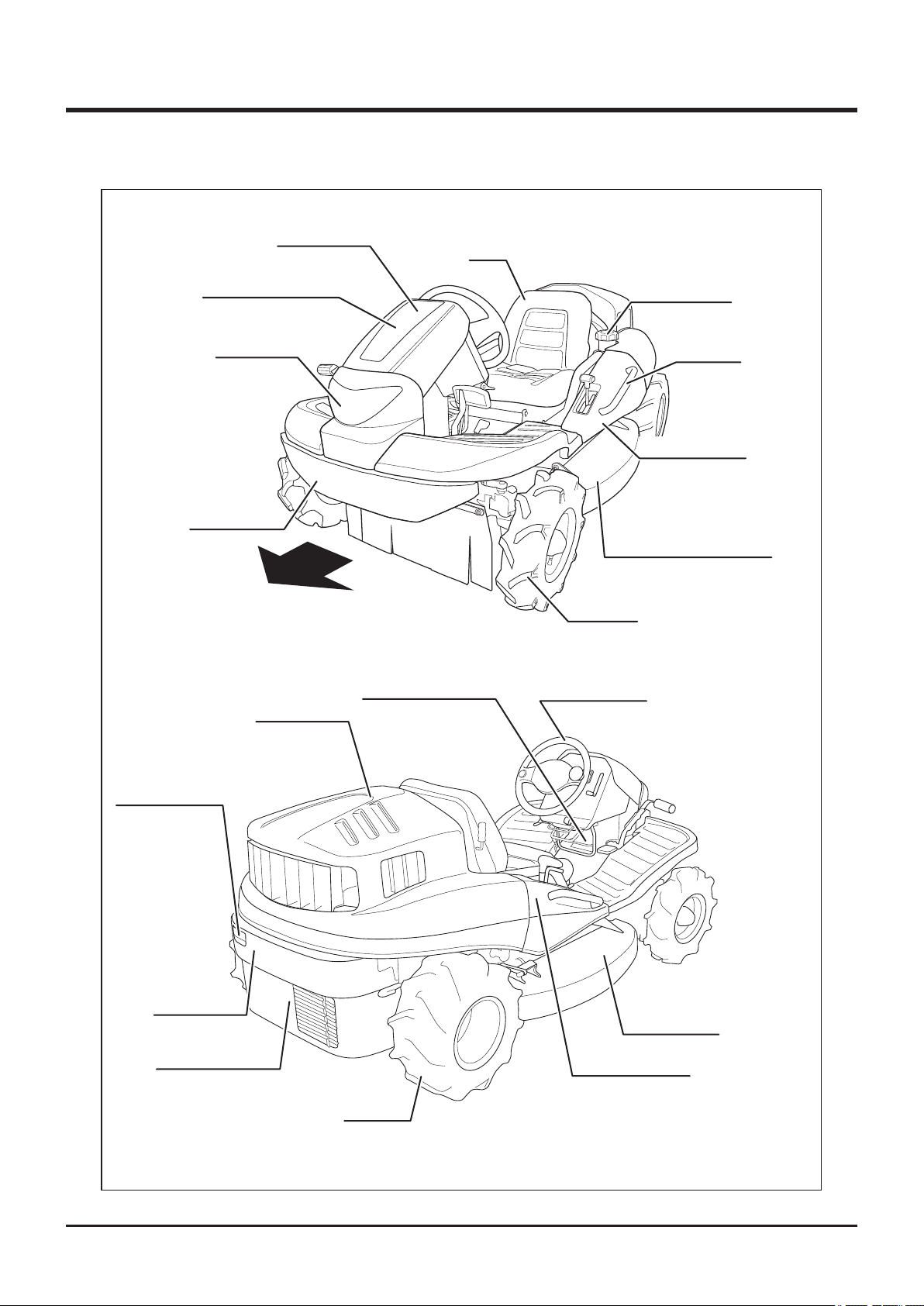
Name and Function of Controls
Front Cover
Tool Box
(Under Front Cover)
Head Lamp
Front Bumper
Forward
Seat
Fuel Filler Cap
Handrail
Side Cover, Left
Cutting Blade Shield, Left
Front Tire
Rear Lamp
(CMX227 Only)
Rear Bumper
Lower Rear Cover
Engine Hood
Plastic Bottle Holder
Rear Tire
Steering Wheel
Cutting Blade
Shield, Right
Side Cover, Right
5335M-0201-010E
-11-
2
Controls and Components
17
15
9
7
6
5
2
13
12
1
14
8
3
5335M-0201-020E
4
16
10
11
-12-

Controls and Components 2
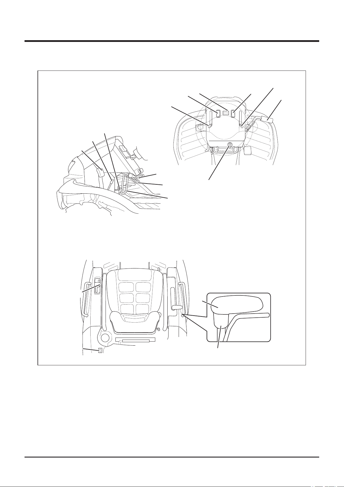
1 Main Switch . . . . . . . . . . . . . Main switch is used to start or stop engine.
2 Throttle Lever . . . . . . . . . . . Throttle lever is used to control engine speed.
3 Drive Pedal . . . . . . . . . . . . . . Drive pedal is used to control the traveling direction and
speed of the machine. Machine moves forward when the
front of drive pedal is depressed and backward when
the rear of drive pedal is depressed. Angle of drive pedal
determines the speed.
4 Drive Lever . . . . . . . . . . . . . . Drive lever is used to control the traveling direction and
speed of machine. Machine moves forward when lever is
tilted forward and backward when lever is tilted backward.
Angle of drive lever determines the speed. (On the right
lever model, this lever is on the right -hand side. See
illustration.)
5 Brake Pedal. . . . . . . . . . . . . . Brake pedal is used to stop machine. When brake pedal
is depressed, drive lever returns to neutral position and
brake is engaged. (On the right lever model, this lever is
on the right -hand side. See illustration.)
6 Parking Brake Lock . . . . . . . Parking brake lock lever is used when parking machine
Lever
7 Auxiliary Transmission . . . . Auxiliary transmission shift lever is used to shift auxiliary
Shift Lever
8 2WD/AWD Shift Lever . . . . . 2WD/AWD shift lever is used to switch between 2WD
securely. Pulling parking lock lever while brake pedal is
depressed locks brake pedal. (On the right lever model,
this lever is on the right -hand side. See illustration.)
transmission to change the speed of the machine.
(on CMX227and CMX186)
9 Differential Lock Lever . . . . Differential lock lever is used to lock differential when rear
(rear-wheel drive) and AWD (all-wheel drive) modes.
wheels slip. Tilting differential lock lever to [ON] position
locks differential.
-13-

2
10 Cutting Height Adjust . . . . . Cutting height adjust lever is used to adjust the cutting
Controls and Components
Lever
11 Cutting Height Adjust
Lock
12 Cutting Rotary Clutch . . . . . Cutting rotary clutch lever is used to start or stop rotating
Lever
13 Tilt Lever . . . . . . . . . . . . . . . . Tilt lever is used to adjust the angle of steering wheel.
14 Head Lamp Switch . . . . . . . . Head lamp switch is used to turn on or off head lamp.
15 Tail Lamp Switch . . . . . . . . . Tail lamp switch is used to turn on or off tail lamp. When
(CMX227 Only)
16 Fuel Gauge . . . . . . . . . . . . . . Fuel gauge indicates the amount of fuel in fuel tank.
height. Grab and hold cutting height adjust lock and move
cutting height adjust lever back or forth to adjust cutting
height.
cutting rotary.
When umain switch is on, head lamp switch illuminates.
umain switch is on, head lamp switch illuminates.
17 Hour Meter . . . . . . . . . . . . . . Hour meter indicates the cumulative total operating time of
the machine in 0.1 hour increments.
-14-

Specications 3
Product Specications
· Use this product properly after understanding its specications thoroughly.
Model and Type
Machine Mass kg
Mowing Rate m
Overall Length mm
Overall Width
Overall Height mm
Wheelbase
Dimensions
Tread
Front
Rear
Ground Clearance
mm
mm
mm
mm
mm
2
/h 7300
CMX227 CM226 CXM186 CM185
345 325 325 320
*1
1947 [1997]
*2
1020
860 [905]
*3
1300
860
800
130 110
7000
1947
840
Model Robin EH65DS Robin EH63DS
Type Air-cooled 4-cycle V-twin Gasoline
Cylinder (Bore×Stroke)
mm
Displacement cm
3
80X65
653
Maximum Output kw(PS)/rpm 16.4(22)/3600 13.4(18.3)/3600
Maximum Torque
Starter System Electric
Engine
N•m(kgf•m)/rpm
45.6(4.65) 43.3(4.42)
Fuel Automotive Unleaded Gasoline
Fuel Consumption
g/kW•h(g/PS•h)
310(230)
*1
Fuel Tank Capacity L 20
Ignition Contactless Magneto
Spark Plug NGK BPR5ES
Battery Type 38B19R
Electrical
Battery Capacity V/Ah 12/28
High
km/h
0 to 13.8 0 to 12.8
Speed
Low
km/h
0 to 7.7 0 to 7.2
Minimum Turning Radius m 1.8
Gradeability Degrees 25 15 25 15
Performance
Stability
Angle
*1 Estimated at the maximum speed with the auxiliary transmission in Low position (7.5km/h)
*2 [ ] indicates the Step Bumper model
*3 [ ] indicates the Extra Seat model
Left Degrees 30
Right Degrees 30
-15-

3
Specications
Model and Type
Main Transmission
Auxiliary Transmission
Tires
Drive Train
Steering
Brakes Internally Expanding
Cutting Width
Cutting Height
Blade Type Free Knife & Stepped Stay
Number of Blades 2
Cutting System
Blade Drive Train Shaft Drive
*These specications are subject to change without notice.
Left AGR 4.00-7 (2PR) AGR 3.50-7 (2PR)
Right 17X8.00-8 (4PR) 16X7.00-8 (4PR)
mm
mm
mm
CMX227 CM226 CMX186 CM185
HST (Continuously
Constant Mesh
Rack and Pinion
Round Steering Wheel
975
0~150 (21 Steps) 0~130 (21 Steps)
Variable)
Contents of Tool Bag
No. Content Quantity Note
1 Operator's Manual 1 This Manual
2
4 Engine Service Tool 1
Operator's Manual for the Engine
1
for Servicing Engine
-16-
Operation 4
Preparation
Pre-start up Inspection
Always perform an inspection before use.
Refer to the Maintenance Schedule (page 40) for the inspection schedule and procedure.
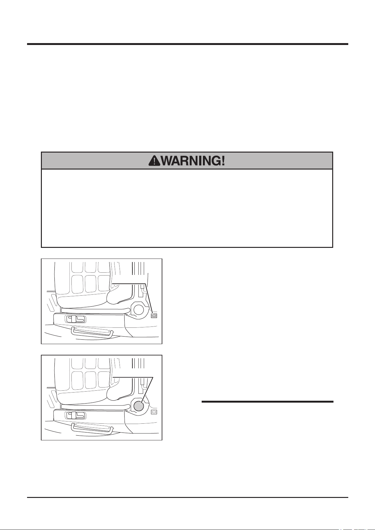
Checking and Filling Fuel
• Keep re and spark away when handling fuel.
• Always stop engine before refueling.
• Do not fill beyond the limit (bottom of the filler filter) so that fuel will not
overow. In case fuel is spilt, wipe out immediately.
1. Check fuel gauge. If fuel level is low, ll fuel.
Fuel Gauge
5332M-0401-010E
2. Open fuel ller cap and ll fuel.
Fuel Filelr Cap
3. Put fuel filler cap back in place and close it
securely.
NOTE
• Fuel : Automotive Unleaded Gasoline
5332M-0401-020E
• Fuel Tank Capacity : 20L
-17-
4
Operation
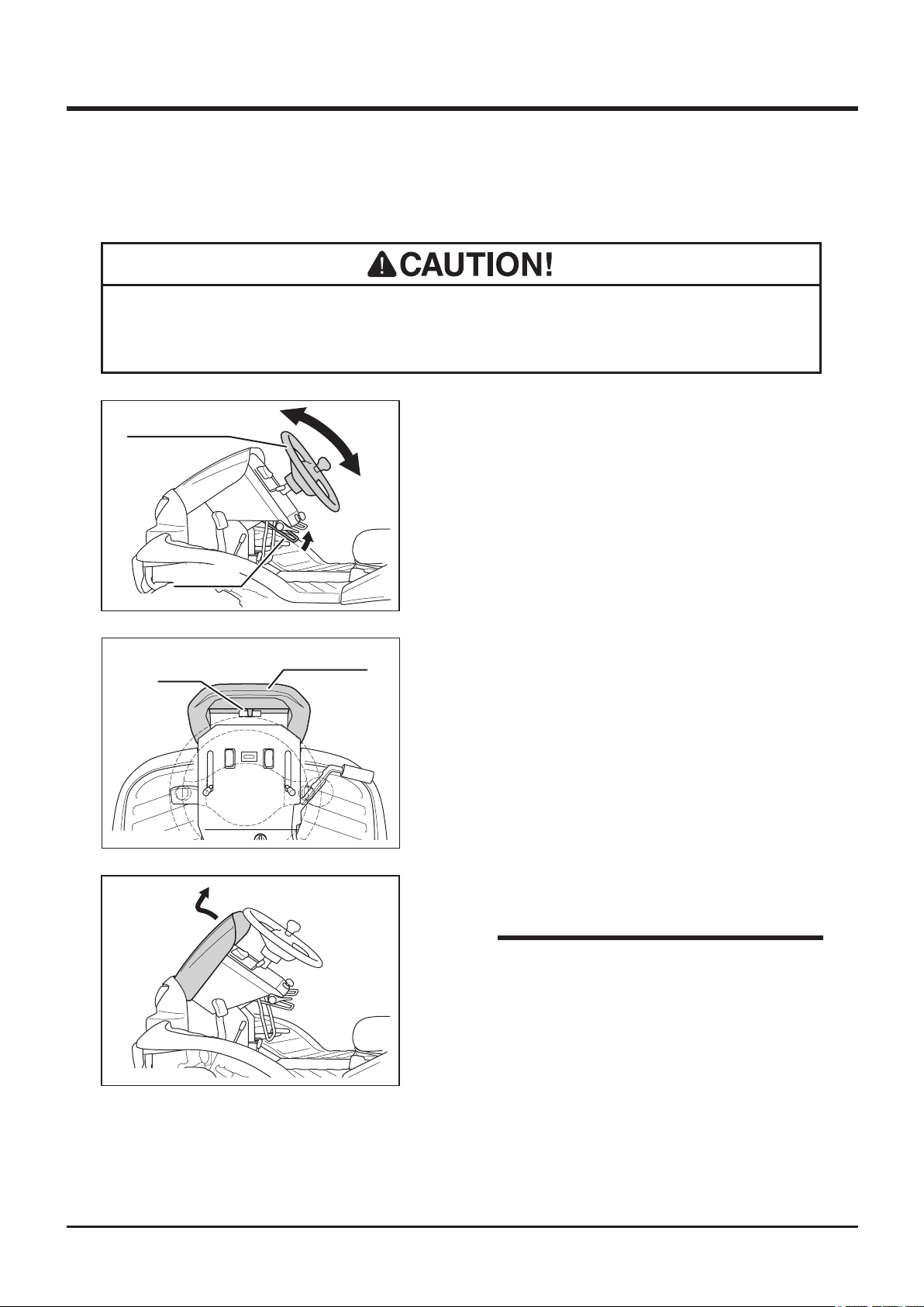
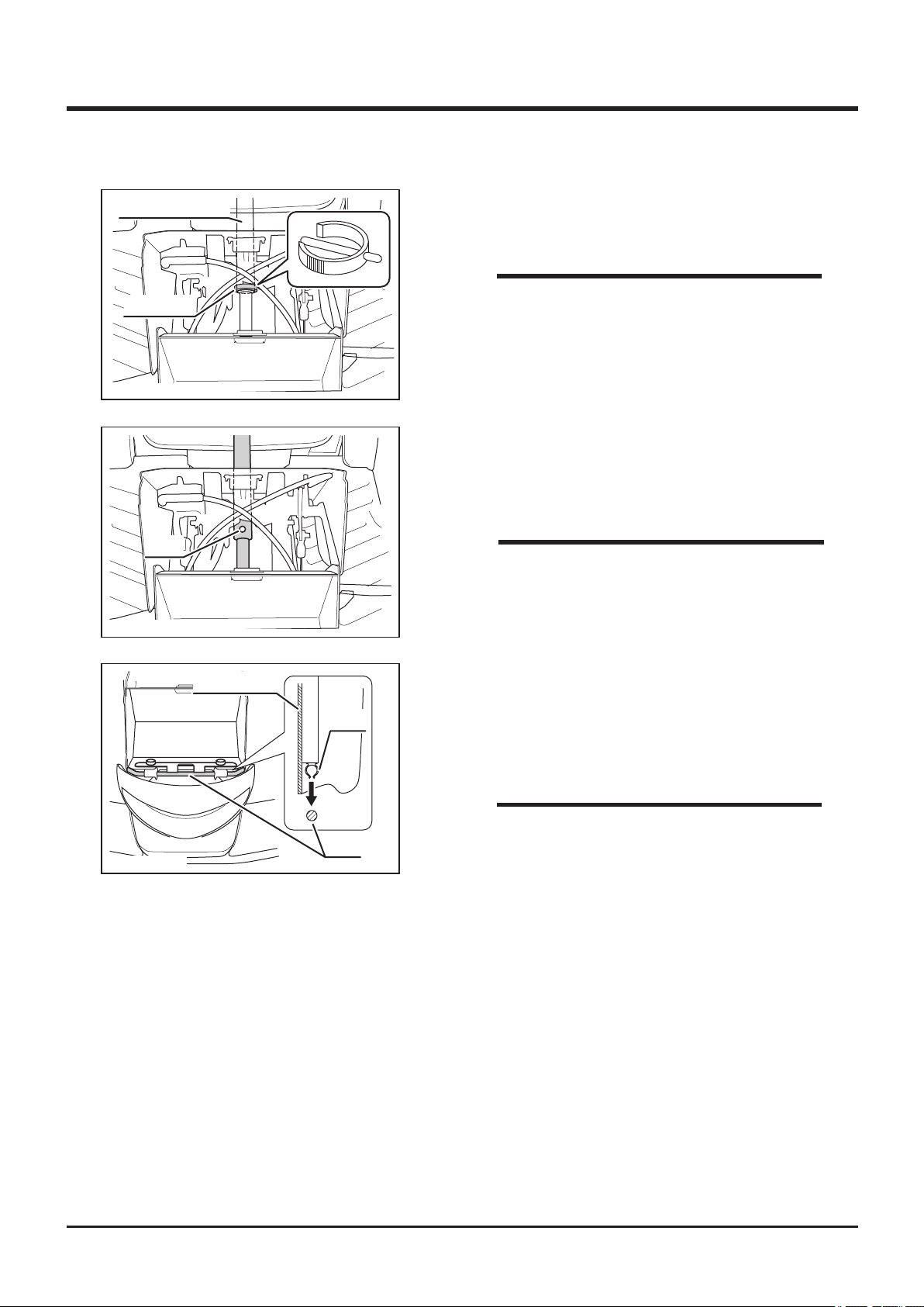
Adjusting Steering Wheel
• After adjusting steering wheel, try moving steering wheel back and forth and up
and down to make sure it is securely locked in its position.
Steering Wheel
5332M-0401-030E
Latch
5332M-0401-040E
Tilt Lever
Front Cover
Adjusting Angle (Tilting)
1. Pull up tilt lever to adjust steering wheel
angle.
2. There are five positions for steering wheel
angle.
3. After adjusting angle, return tilt lever to lock
steering wheel securely.
Adjusting Height
1. Pull top edge of front cover to unlock latch.
5332M-0401-110E
2. Pull out front cover.
NOTE
• Inside of the front cover is made as tool
box. Use this box to store items such as
tools or substitute cutting blades.
-18-
Operation 4
Steering Column
Fixing Pin
5332M-0401-120E
Hole
5332M-0401-130E
3. Remove fixing pin from steering column in
the front of machine.
NOTE
• If fixing ping is in the difficult direction to
remove, steer the steering wheel to change
direction of the pin so that the pin can be
easily removed.
4. Adjust steering wheel height in prefered
position. Line up holes on steering shafts and
insert pin.
NOTE
• Move steering wheel up and down to check
if the steering wheel is xed securely.
5332M-0401-140E
Front Cover
Clip
Rod
5. Raise steering wheel angle.
6. Fit clip on back side of front cover into the
rod.
7. Latch top edge of the front cover.
NOTE
• Pay attention not to catch the front cover by
the plate on both sides when installing front
cover.
-19-
4
Operation
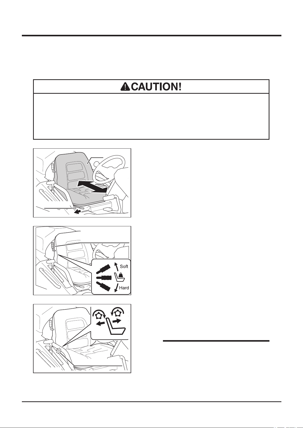
Adjusting Seating Position
• Beware of pinch points when adjusting seating position.
• After adjusting seat, try moving seat back and forth and up and down to make
sure it is securely locked in its position.
Slide Lever
5332M-0401-050E
5332M-0401-060E
Seat
Seat Suspension
Stiffness Adjust Lever
Sliding seat
1. Pull slide lever to the right to slide seat
forward or backward.
2. When seat is in a desired position, release
slide lever and lock seat securely.
Adjusting Stiffness
1. Move seat suspension stiffness adjust lever
to adjust desired seat stiffness.
5332M-0401-071E
Reclining Adjust Knob
Adjusting Reclining Angle
1. Rotate reclining adjust knob on the right of
seat to adjust reclining angle of the seat.
NOTE
• Do not ajust seat posision to the end and
recline the seat. The seat may contact with
rear cover. This may activate seat switch
and stop engine. Adjust seat in the range of
not contacting with rear cover.
-20-
 Loading...