

Page 1
CHIKUSUI CANYCOM, INC.
90-1 Fukumasu, Yoshii-machi,
Ukiha city, Fukuoka, Japan 839-1396
Tel. 81-(0)943-75-2195 Fax. 81-(0)943-75-4396
Ride-on Brushcutter
CM 230
OPERATOR'S MANUAL
October 2005, 5317 5201 000 01
* Read this manual completely before operating or maintaining this machine.
Failure to follow safety precautions could result in serious injury or death.
* Keep this manual for future reference for you and for all those who operate
and maintain this machine.
Page 2

Memo of address and telephone number
(Name of dealer)
■
Sales Headquarters
0943(75)2195 FAX (75)4396
■
Foreign Trade Center
03(3552)6277 FAX (3552)6288
■
Tok y o Cente r
03(3552)6255 FAX (3552)6288
■
Sendai Center
022(281)1255 FAX (281)3141
■
Saitama Center
0495(77)4511 FAX (77)1561
■
Osaka Ce nter
0790(42)6031 FAX (42)6035
■
Hiroshima Center
0824(34)5996 FAX (34)5997
■
Matsuyama Center
089(983)2701 FAX(983)5749
■
Fukuoka Center
0943(76)2583 FAX (75)5126
■Kagoshima Center 0995(58)3011 FAX (58)2344
CHIKUSUI CANYCOM, INC.
We prohibit unauthorized reprinting and reproduction of this document.
Page 3

Contents
Introduction 1
Introduction …………………………………………………… 1
Safety Rules 2
Safety Declaration
……………………………………………
2
Safety Operation (B71.4) …………………………………… 2
Training ……………………………………………………………………………… 2
Preparation …………………………………………………………………………… 2
Operation……………………………………………………………………………… 3
Maintenance and Storage …………………………………………………………… 4
Rules for Safe Operation and Work ………………………… 5
Safety Precautions Before Operation ……………………………………………… 5
Do Not Start, Accelerate, Turn, or Brake Quickly ………………………………… 6
Safety Precautions When Operating
………………………………………………
7
Precautions When Parking ………………………………………………………… 8
Precautions When Performing Maintenance ……………………………………… 9
Inclination measuring Gage …………………………………10
Warning Words Used in This Manual ……………………… 11
Explanation of Warning Labels on the Machine…………… 12
Specications 15
Specications
…………………………………………………
15
Gasoline and Oil 17
Explanation of Gasoline ……………………………………… 17
Recommended Gasoline ………………………………………………………… 17
Refueling fuel tank ………………………………………………………………… 18
Explanation of Oil
……………………………………………
19
Page 4

Recommended Oil ………………………………………………………………… 19
Inspecting Engine Oil ……………………………………………………………… 19
Preparation 20
Details of Attachments ………………………………………20
Preparation for Starting ………………………………………20
Adding Grease and Oil …………………………………………………………… 20
Inspecting Engine Oil ……………………………………………………………… 21
Inspecting HST Oil
…………………………………………………………………
22
Checking Tire Pressure ………………………………………………………… 23
Checking Rotary Height ………………………………………………………… 23
Checking Grass Chute Cover …………………………………………………… 24
Operation 25
Observance of Safety First …………………………………25
For Use of ROPS ……………………………………………25
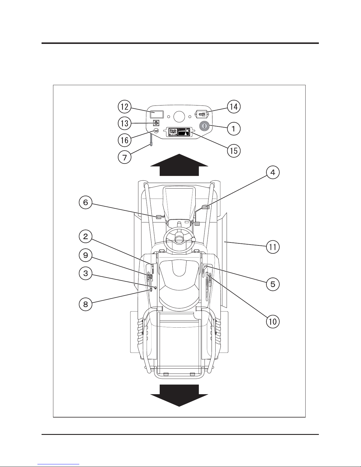
Component Names and Functions …………………………26
Location
……………………………………………………………………………
26
Component Names Functions and Operations ………………………………… 27
How to Drive ………………………………………………… 28
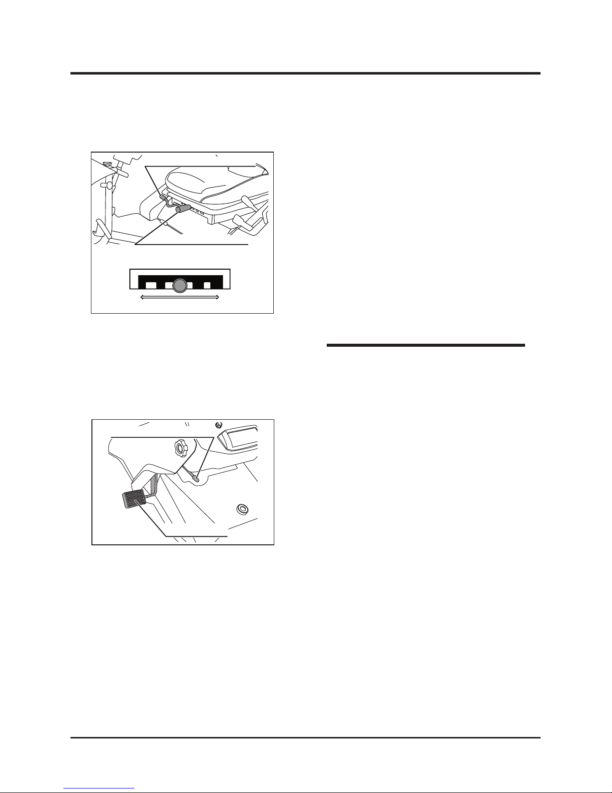
How to Adjust Seat………………………………………………………………… 28
How to Apply Parking Brake……………………………………………………… 28
Explanation of Safety Interlock…………………………………………………… 28
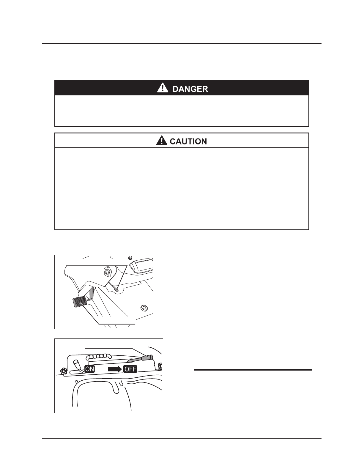
Starting……………………………………………………………………………… 29
Operating…………………………………………………………………………… 33
Stopping …………………………………………………………………………… 35
How to Perform Work…………………………………………37
Checking Cutting Blades ………………………………………………………… 37
Adjusting Blade Height …………………………………………………………… 37
Working Procedure
………………………………………………………………
38
Transportation …………………………………………………41
Loading …………………………………………………………………………… 41
Lifting by Crane …………………………………………………………………… 42
Emergency Transferring ………………………………………………………… 43
Page 5

Maintenance 44
Periodic Check Sheet ………………………………………44
Fuel / Grease / Lubricant / Fluid Chart ……………………47
Consumable (Replacement Parts) Chart …………………48
Engine …………………………………………………………49
Inspecting, Adding and Replacing Engine Oil
…………………………………
49
Replacing Engine Oil Filter ……………………………………………………… 51
Cleaning and Replacing Air Cleaner …………………………………………… 52
Cleaning Cooling System ………………………………………………………… 53
Inspecting, Cleaning, and Replacing Ignition Plug …………………………… 53
Fuel System
……………………………………………………
55
Draining Fuel ……………………………………………………………………… 55
Inspecting Fuel Filter ……………………………………………………………… 56
Hydraulic System ……………………………………………57
Inspecting, Adding and Replacing HST Oil
……………………………………
57
Replacing HST Oil Filter ………………………………………………………… 59
Running System ………………………………………………60
Inspecting, Adding and Replacing Transmission Oil…………………………… 60
Replacing Differential Oil and Knuckle Oil ……………………………………… 61
Inspecting and Adjusting Driving V-Belt ………………………………………… 62
Adjusting Brake Pedal …………………………………………………………… 62
Checking Tire Pressure ………………………………………………………… 63
Checking Wheel Bolts …………………………………………………………… 63
Electrical Equipment …………………………………………64
Inspecting Battery Electrolyte and Adding Water ……………………………… 64
Charging Battery
………………………………………………
65
Electric Circuit Diagram ………………………………………67
Cutting Unit ……………………………………………………68
Opening Grass Chute Cover …………………………………………………… 68
Inspecting and Replacing Cutting Blades
………………………………………
69
Page 6

Inspecting and Adjusting Rotary Driving V-Belt………………………………… 71
Inspecting and Adjusting Rotary Cutter Brake ………………………………… 71
Lubrication and Greasing ……………………………………73
Disposal of Waste ……………………………………………73
Storage 74
Maintenance After Use ……………………………………… 74
Maintenance After Use in Normal Conditions ………………………………… 74
Maintenance After Use in Cold Season ………………………………………… 74
Long-Term Storage…………………………………………… 75
Troubleshooting 76
Troubleshooting ……………………………………………… 76
Guarantee and After-Sales Service 79
Guarantee and After-Sales Service …………………………79
Guarantee
…………………………………………………………………………
79
After-Sales Service ……………………………………………………………… 79
Availability of Replacement Parts ……………………………………………… 79
Page 7

-1-
Introduction 1
Location of model label
5317M-0101-010-E
Please read this manual to completely understand the machine operation and maintenance
procedures before using the machine. Following this manual’s instructions may help avoid
human injury and mechanical damage. This machine has been designed and manufactured
with due regard to safety. Operators and service staff however, should also take safety
precautions when working with this machine. For service, genuine parts, or questions about
the machine, consult the dealer from whom you purchased the machine. Tell the dealer the
machine model and product numbers indicated on the model label, as shown below.
Write the model and product numbers in the table below for easy future reference.
Introduction
Location of Model Label Model Label
Machine identification table
Model
Product No.
5317M-0101-020
Introduction
Page 8

Safety Rules
-2-
2
This machine meets the requirements of ANSI B71.4 2004, which was being valid at the time
it was manufactured. The ROPS installed in the machine meets the requirements of SAE
J2194 Standard, and the ROPS conforms to the requirements of OSHA1928.52.
Safety Declaration
* Operating this machine equipped with one or more attachments produced by
any other manufacturer will not meet the requirements of the ANSI standard.
Improper use and insufficient maintenance may cause damage to the owner
or operators of the machine. In order to avoid accidents, observe safety
operations, especially descriptions with the warning symbol "!". Not complying
with these warnings may result in serious injury or death.
Safety Operation (B71.4)
1. Read and understand the manuals and other educational material. The owner of the
machine is responsible for explaining the contents of these documents to his operators
and maintenance staff who do not understand English.
2. Read and understand the safety operation and warning labels pasted on the machine.
3. All operators and maintenance persons must be trained. The owner of the machine is
responsible for training people all staff who will work with this machine.
4. Children or untrained people should never operate or maintain this machine. Local
ordinances regulating the operator’s age limits should be observed.
5. The owner and operators of the machine are responsible for protecting people and
property from any accidents and injuries during operation.
Training
1. Check the operating area before deciding the accessories and attachments required
for safe operation. Only use accessories and attachments approved by CHIKUSUI
CANYCOM, INC. (hereafter called “Manufacturer”).
2. The operators of the machine must wear proper protective clothing including safety
helmets, protective glasses, ear plugs, etc. Long hair, loose clothes, jewelry or other
accessories which could be caught in rotating parts should be removed or secured.
3. Before using the machine remove all obstacles from the operating area (stones, toys,
wires, etc.) which could be thrown by the machine or cause damage to the machine.
4. Handle gasoline or other fuels with extreme care to avoid flame and explosion risks.
a. Only use certified containers for storing and transporting fuel.
b. Never start the engine when the fuel tank cap is removed or during refueling. Do not
Preparation
Safety Rules
Page 9

-3-
Safety Rules 2
1. Do not start the engine in a closed space.
2. Operate the machine in an area that is free from holes and dangerous material and where
operator can maintain good visibility.
3. Put the driving system into neutral and apply the parking brake before starting the engine.
Start the engine with operator sitting in the operator’s seat. Fasten the seat belt after
starting engine.
4. Reduce speed when operating the machine on inclined areas. Move the machine in
recommended directions on inclined areas. The grass condition affects the stability of the
machine. Use special care when operating the machine on areas where there is a risk of
turnover.
5. When changing driving direction on inclined areas. Reduce speed and use extreme care.
6. Never open the rotary cutter cover when the rotary cutter is rotating.
7. Always attach and close cutter cover before driving and grass cutting.
8. Do not change the adjusted position of the engine governor and do not increase the
rotation speed of the engine.
9. When parking the machine, park on level ground, disconnect the rotary cutter from the
driving system, and apply the parking brake. Leave the operator’s seat after stopping the
engine, and remove grass choking the rotary cutter.
10. When a sudden impact or irregular vibration occurs in the rotary cutter during cutting,
stop the machine to check the cause operation. Confirm rotary cutter and machine are
not damaged before restarting the work.
11. Keep hands and feet off the rotary cutter unit.
12. Periodically check the machine rear and under carriage areas for potential problems.
13. Do not carry passengers on the machine and do not let people or pets stand close to the
machine during operation.
14. When driving the machine across a road or pedestrian crossing, reduce its speed and
use care. Stop the rotary cutter after ending cutting operations.
15. Do not direct the grass outlet toward people.
16. Do not drive and operate machine when under the influence of alcohol or drugs, or when
fatigued.
17. Use caution when loading or unloading the machine into or out of a truck or trailer.
18. Use caution when approaching corners, bushes, trees, and other obstacles where
visibility is poor.
Operation
smoke near machine during refueling.
c. Do not add or remove fuel indoors.
5. Confirm that the seat-adjusting device for the operator, safety switches, and shields are
installed and function properly before using machine. If they do not function properly, do
not operate the machine.
Page 10

Safety Rules
-4-
2
1. Before maintaining or storing the machine, disconnect the running and cutting systems
from their driving units, apply the parking brake, and pull the ignition plug cord out. Before
storing the machine, adjust, clean, and repair the movable parts.
2. Remove remaining grass and foreign matter from the cutter blades and under carriage to
prevent fires.
3. Cool the engine completely and do not place any flammable material near the machine.
4. Park the machine on level ground. Any person not trained to handle the machine should
not maintain the machine.
5. Use jacks if necessary to raise machine.
6. Carefully relieve pressure from the pressurized parts.
7. Always remove the battery cords and ignition plug cords before repairing any part.
Remove the minus side first, and then the plus side. Install the plus side first, and then
the minus side.
8. Check the cutting blades with caution by covering the blades with proper material or
wearing protective gloves. When replacing the cutting blade, do not straighten or weld it.
9. Keep hands and feet off the moving parts. Do not make adjustments when the engine is
operating.
10. Charge the battery in a well ventilated area without sparks or flammable material nearby.
Pull the charger power plug out before connecting or disconnecting the charger to or from
the battery. Wear protective clothing and use insulated tools.
11. Keep all parts in clean, dry storage and ensure that they are correctly installed. Replace
all deteriorated labels with new ones.
Maintenance and Storage
Page 11

-5-
Safety Rules 2
Rules for Safe Operation and Work
Perform the daily pre-operation check before
starting the machine.
Repair or replace damaged parts before starting
the machine.
Pre-work Check
This chapter shows the general safety precautions to be observed during driving or
operation. Try to carry out driving or operation safely by being sure to follow the safety
instructions in other chapters as well.
Do not handle fuel or grease, service the engine,
or recharge the battery while smoking or when
near an open flame.
Fuel Handling
Wear clothes suitable for driving and operating
the machine. Casual wear and sandals should not
be use for driving and operating. Wear protective
accessories such as protective helmets, shoes,
glasses, and gloves.
Wear proper clothes and protective
accessories
CM-01-030
CG-01-010
CM-01-020
Safety Precautions Before
Operation
Page 12

Safety Rules
-6-
2
This machine has one seat only: the operator’
s seat. It is extremely dangerous to drive this
machine with passengers. Never allow a person
or persons other than the operator to ride on the
machine.
Do Not Carry Passengers on This Machine
Do not operate this machine when under the
influence of alcohol or drugs or when fatigued.
No one under age 18 should operate this vehicle.
Do Not Drive Recklessly
Before starting the machine, always confirm the
conditions of the operating area, and drive it at
a safe speed according to the inclination and
surface conditions of the operation area.
Observe Safety Speed
Drive safely and avoid sudden changes of speed
or direction. Make sure the area around the
machine is safe for driving. Do not make sudden
maneuvers or turn sharply when driving on soft or
wet ground; this can cause the machine to lose
traction or turn over.
CM-02-010
CM-02-020
CM-01-040
CM-01-050
Avoid Quick Starting, Accelerating,
Turning and Braking
Do Not Start, Accelerate, Turn,
or Brake Quickly
Page 13

-7-
Safety Rules 2
Stop before driving downhill, shift the auxiliary
speed change lever to the “LOW” speed position,
and drive downhill at reduced speed.
Reduce Driving Speed going Downhill
Post notice boards before that operation to show
that job site is under operation. If necessary,
apply guard ropes to enclose and restrict access
so that people (especially children) may not enter
the work area and safety may be ensured.
Secure Area (No Admittance) During
Operation
Use care during operation to avoid throwing
stones and small objects that may be
dangerously toward nearby persons, animals,
crops, cars or other objects.
Beware of Flying Objects
Before performing cutting work, always check
holes and other obstacles in the operation area.
Use caution to avoid these obstacles.
Safety Precautions When
Operating
CM-03-010-E
Of
f Limit
CM-02-030
CM-03-020
CM-03-030
Caution for Holes and Obstacles
Page 14

Safety Rules
-8-
2
Always travel straight up or down a slopes.
Never travel across slopes or along contour lines.
Driving across steep slopes or along contour lines
is dangerous and may cause the machine to tip
over, causing serious injury or death.
Beware of driving in trenches and on banks.
There is a danger of the ground crumbling due
to the machine weight. When travelling on soft
ground, drive slowly and safely.
Precautions on Crumbling Ground
When parking always apply brake and stop
engine. Always remove key.
Safety Actions When Parking
Park the machine on stable, level, flat surfaces.
Do not park on unstable or inclined surfaces.
Do Not Park on Unstable or Inclined
Surfaces
CM-03-040
CM-03-050
CM-04-010
CM-04-020
Precautions When Parking
Avoid Driving Across Slopes
Page 15

-9-
Safety Rules 2
Avoid parking the machine on slopes. If there
are no other options, apply the parking brake
securely and block the wheels at the lower end .
Do not carry out maintenance with the engine
running. Always stop the engine before starting
maintenance.
When operating engine indoors, always ensure
that there is adequate ventilation to prevent
poisoning by exhaust gas.
Ventilate Properly When Operating
Indoors
Avoid Parking on Slopes
CM-04-030
CM-05-010
CM-05-020
Precautions When Performing
Maintenance
Never Carry Out Maintenance with Engine
Running
Page 16

Safety Rules
-10-
2
Inclination measuring Gage
EXAMPLE:COMPARE
SLOPE WITH FOLDED EDGE
ALIGN THIS EDGE WITH A VWRTICAL SURFACE
(TREE,BUILDING,FENCEPOST,POLE ETC.)
THIS IS
A
5°SLOP
E
THIS IS A
10°SLOP
E
THIS IS A
15°SLOP
E
THIS IS A 20°SLOP
E
FOLD ALONG APPROPRIATE LINE
5317M-0204-010
Copy this page. Do not remove from this manual.
Page 17

-11-
Safety Rules 2
Warning Words Used in This Manual
Signal word Meaning
In dicate s an i mmine ntly h a z ardous situ ation w hich, if not
avoided by following these instructions and precautions, could
result in serious injury or death.
Indicates a potentially hazardous situation which, if not avoided
by following these instructions and precautions, could result in
serious injury or death.
Indicates a potentially hazadous situation which, if not avoided
by following these instructions and precautions, may result in
minor or moderate injury.
This word is used for precautions that are recommended or to
emphasize the importance of information.
To indicate the level of danger (or the degree of the failure), the following four signal words
are used to identify the safety messages in this manual. Their meanings are as follows:
NOTE
* The machine can be very dangerous if the safety precautions in this manual
and on the labels attached to this machine are not followed. Always follow the
instructions and safety precautions or serious injury or death could result.
* This machine is a work vehicle for mowing. Do not use it for other purposes.
Any other use could be dangerous.
* Driving this machine on a public road or a road regarded as a public road may
be illegal, depending on local regulations.
* Do not modify this machine. Also do not remove the safety cover of the body
before running. A serious accident could result.
Page 18

Safety Rules
-12-
2
Explanation of Warning Labels on the Machine
NOTE
*Replace these labels immediately if they have been removed, have fallen off, or have become
illegible. Use the part numbers on the label to order replacement labels from dealer.
5317M-0206-010
Page 19

-13-
Safety Rules 2
1
2
3
4
5
6
7
5317M-0206-020-E
1211
Page 20

Safety Rules
-14-
2
5317M-0206-030-E
5316 5003 000 5316 5004 000
Page 21

-15-
Specications 3
* Read and understand specifications before using this product.
Specifications
Model CM230
Machine weight kg 490
Machine dimensions
Overall length mm 2170
Overall width mm 1110
Overall height mm 1840
Wheel base mm 1460
Tread
Front mm 810
Rear 900
Minimum freeboard mm 115
Engine
Model - Air-cooled 4-cycle gasoline
Type - KAWASAKI FH680V
Cylinder (Bore X Stroke) mm 75.2 × 76.0
Total displacement cm3(cc) 675 (675)
Maximum output
㎾
[ps] / rpm
17.2 [23] / 3600
Starting system Self-starter type
Fuel used Gasoline
Fuel tank capacity Liter 30
Ignition plug no. - NGK BPR4ES
Electrical
device
Battery type - 40B19R
Battery capacity V / AH 12 / 28
Travelling performance
Travelling speed
Low
km / h
0 - 6.0
High
km / h
0 - 9.0
Minimum turning radius m
1.9
Gradeability degree
25
Stability inclination
angle
Left degree
30
Right degree
30
test result
(standstill)
Left degree
42
Right degree
41
Specications
Page 22

Specications
-16-
3
Model CM230
Power transmission
device
Main speed shift HST (Hydrostatic) drive
Steering device - Rack and pinion type round steering wheel
Brake type - Internal expanding type brake
Tire
Front wheel
- 4.00-7
Rear wheel
- 17 × 8.00-8
Cutter blade
Blade type mm Free knife & stepped stay
Cutter blade width mm 900
Cutter blade height mm
30 ~ 11 0 (free stage)
Noise level
dB 92
* These specifications are subject to change without notice, for product improvement.
Page 23

-17-
Gasoline and Oil 4
Explanation of Gasoline
Recommended Gasoline
* Use fresh lead-free gasoline. In order to prevent knocking, use gasoline with a
octane number higher than 87. If knocking still occurs, replace the gasoline brand
or with an even higher octane number composition.
* Do not use fuel containing alcohol.
Gasoline and Oil
Page 24

Gasoline and Oil
-18-
4
1. Open the fuel tank cap.
2. Add fuel.
* Gasoline may cause res or explosions leading to serious injuries or death.
Always refuel the fuel tank outdoors in open air.
* When adding fuel, keep open flames (lighted cigarettes, etc.) away from fuel and
engine. Flames will cause the fuel to ignite.
* Always stop the engine before adding fuel.
* Do not overfill so that fuel spills out of filler cap. Wipe up any spilled fuel before
starting engine.
Refueling fuel tank
* Refuel the fuel tank so that the fuel surface does not exceed the upper limit
(equal to the bottom level of the filter installed in the fuel inlet port) to reduce
the risk of fire.
* Perform refueling slowly, or the fuel may spill over the fuel inlet port.
Filter
Upper limit of oil level
(Base of filter)
Fuel tank cap
5310M-0601-010-E
* Refueling should be done slowly. The fuel
tank is divided into right and left sections. It
takes 2 to 3 minutes until the fuel levels of
both sections become even.
NOTE
3. Close the fuel tank cap firmly.
Page 25

-19-
Gasoline and Oil 4
Inspecting Engine Oil
1. Park machine on level ground.
2. Open the engine cover.
3. Pull out the oil gauge. Clean the gauge with
clean cloth. Reinsert to measure oil level.
Inspection
NOTE
4. When the oil level is lower than the range
indicated by "A" on the oil level gage, add fresh
specified engine oil.
5. When the oil is dirty or has deteriorated into
lower viscosity, replace it with fresh oil.
6. After adding oil, securely attach the cap of the
oil inlet port.
Filler cap
Oil level gauge
* Always stop the engine before checking the engine oil.
Explanation of Oil
Recommended Oil
Use the oil specified by the manufacturer as show in the list of specifications for oil, grease,
fuel, and water. (See Page 47)
5310M-0601-040-E
5310M-0601-050-E
* Check the amount of oil before the engine is
started or at least 10 minutes or more after
the engine has stopped. Immediately after
the engine is stopped, oil still remains in parts
of the engine, so oil checks are not accurate.
Page 26

Preparation
-20-
5
Details of Attachments
Before using the machine the first time after purchasing it, perform the following inspections
and checks.
Preparation for Starting
Adding Grease and Oil
When using a manual grease pump, push its handle five to six times. When resistance
becomes heavy, immediately stop pushing. When using a pneumatic grease pump,
pumping for two to three seconds is enough.
* Periodically perform greasing and oiling. Neglected grease and oil may
result in parts seizing and rusting, which may hinder the smooth rotation and
operation of the machine.
Grease point
Oil point
5317M-0502-010-E
Before using the machine the first time after purchasing it, check that all the attachments
shown below are available.
Part name Quantity Remarks
1
Operator's manual
1
This manual
2
Instruction manual for engine
1
3
Plug wrench
1
4
Closed wrench
1
Preparation
Page 27

-21-
Preparation 5
Inspecting Engine Oil
1. Park machine on level ground.
2. Open the engine cover.
3. Pull out the oil gauge. Clean the gauge with
clean cloth. Reinsert to measure oil level.
Inspection
4. Check the oil level visually and confirm that the
oil level is within the range indicated by "A" on
the oil level gage.
5. After adding oil, securely attach the cap of the
oil inlet port.
Filler cap
Oil level gauge
5310M-0601-050-E
* Check the amount of oil before the engine is
started or at least 10 minutes or more after
the engine has stopped. Immediately after
the engine is stopped, oil still remains in parts
of the engine, so oil checks are not accurate.
NOTE
* Always stop the engine before checking the engine oil.
5310M-0601-040-E
Page 28
Preparation
-22-
5
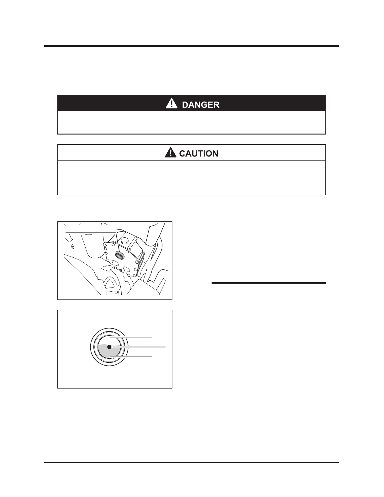
Inspecting HST Oil
Oil level guage
* Always stop the engine before checking the engine oil.
1. Park machine on horizontal surface.
2. Open the engine cover.
3. Check the HST oil level in the oil level gauge.
Inspection
Oil level guage
Proper amount
HIGH
LOW
* Maintain proper oil level to prevent air from entering system and disrupting
smooth operation.
* Check the amount of the hydraulic oil before
starting the engine. The amount of the HST
oil cannot precisely be measured just after
the engine is stopped.
NOTICE
5317M-0502-030-E
5116M-0507-020-E
Page 29
-23-
Preparation 5
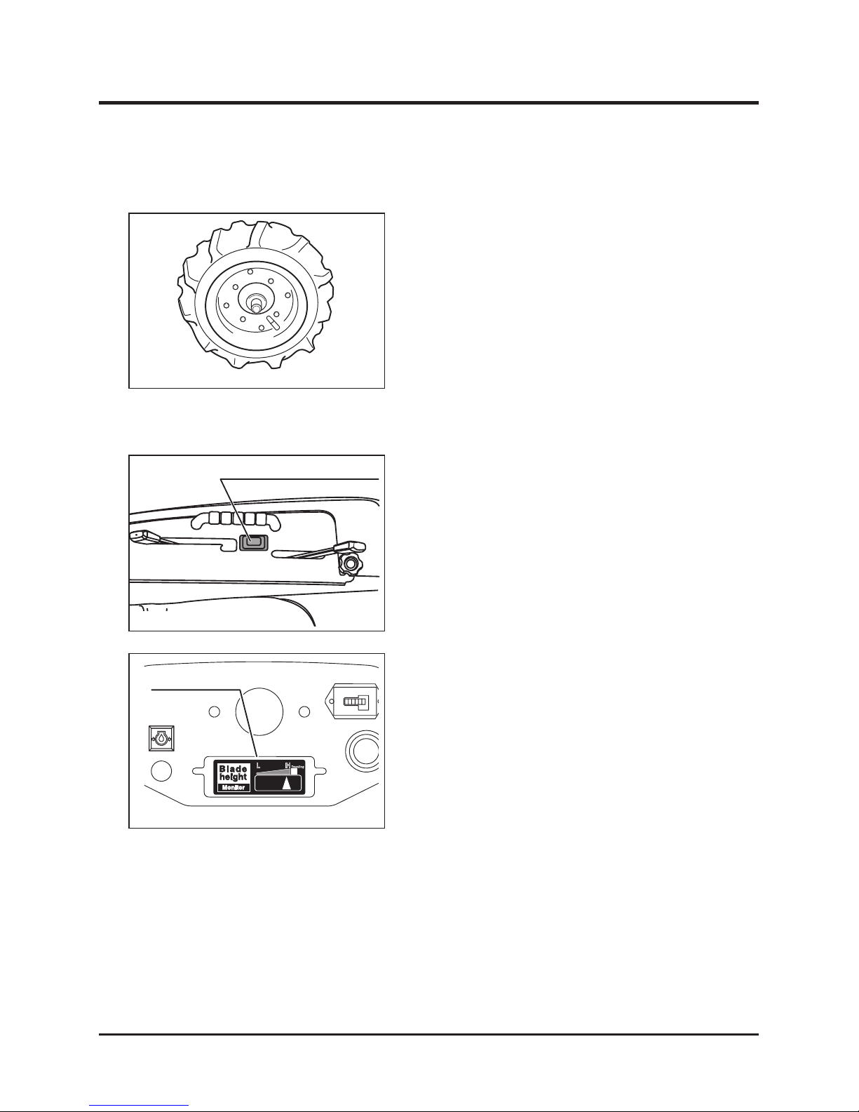
Checking Rotary Height
Checking Tire Pressure
1. Check the pressures of the front and rear
wheel tires. If they do not meet the standard
value, adjust them.
In order to prevent flat tires, the boundary
zones between the tires and hubs outside
and inside the wheels are filled with a tire
protective agent (Ultraseal).
5317M-0502-020
1. When adjusting cutting height by pushing the
rotary blade height adjusting switch, confirm
that the monitor is connected to indicate the
adjusted cutting height.
Rotary height adjusting switch
5314M-0602-030-E
Blade height monitor
5317M-0502-040-E
Page 30
Preparation
-24-
5
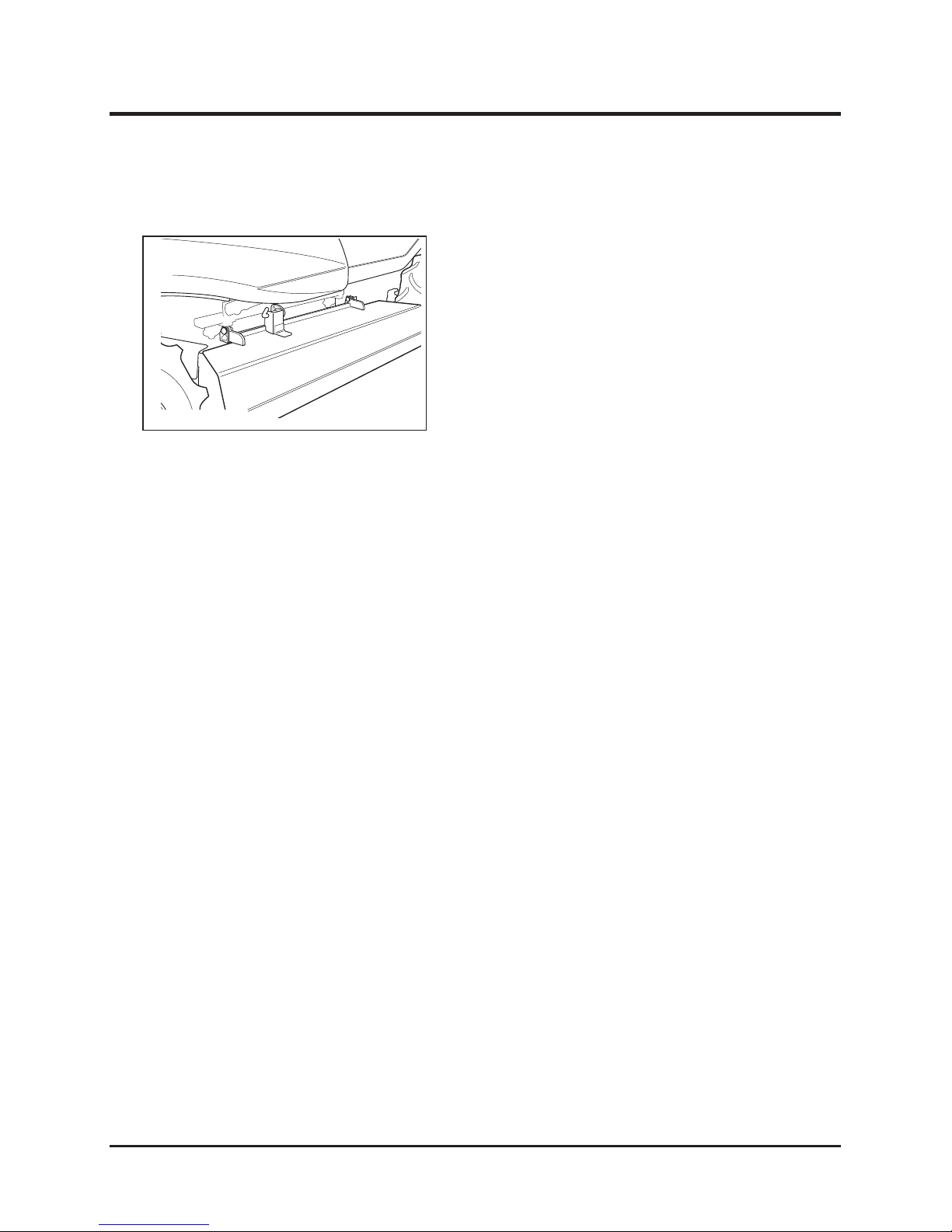
Checking Grass Chute Cover
1. Confirm that the safety pins for stopping the
opening/closing movement of the grass chute
cover are securely inserted.
5317M-0502-050-E
Page 31
-25-
Operation 6
When using the machine, observe the "Safety Rules".
Observance of Safety First
For Use of ROPS
* Never perform cutting work when the ROPS has been removed.
A turnover during cutting work in an inclined area is extremely dangerous.
A machine without the ROPS installed does not meet the requirements of
OSHA1928.52.
Operation
Page 32
Operation
-26-
6
Location
FORWARD
REVERSE
5317M-0603-010-E
Component Names and Locations
Page 33

-27-
Operation 6
Component Names, Functions and Operations
1 Main switch
…………………………
Start or stop engine with this switch.
* When the machine is not used remove and keep the key.
2 Accelerator lever … … … … … …… Increases and decreases engine speed.
3 Choke lever ………………………… When the lever is pulled out, the choke valve closes. When
lever is pushed in, the choke valve opens. Pull the lever when
starting the engine and push in after the engine is started.
4 HST pedal ………………………… When the pedal is depressed forward from the neutral
position, the machine moves forward. When the pedal is
depressed backward, the machine moves backward. The
running speed can be innitely adjusted by changing the
depressed angle of the pedal.
5 Speed change lever
……………… Use this lever when shifting speed to high / low levels.
WARNING: Do not change gears while driving.
6 Brake pedal ………………………… Press to stop the machine when driving.
7 Parking brake lock lever ………… When the lock lever is lowered with the brake pedal pressed
down, the brake pedal is locked.
8 Differential lock lever ……………… Use this lever when one of the rear wheels slips. When the
lever is moved to “ON”, the differential lock is engaged. When
the lever is moved to “OFF”, the differential lock is disengaged
(normal driving position).
*During normal driving, always put the lever to “OFF” position.
9 Blade height adjusting switch …… Adjusts the cutter blade height.
10 Blade clutch lever ………………… Turns the blade power on and off.
When pushing this lever to "OFF", the cutter brake pulley is
engaged and the brake is applied.
11 Cutter blade cover
………………
This cover prevents pebbles and foreign matter from shooting
out during operation. When replacing the cutter blade, open
this cover to facilitate the cutter blade replacement operation.
12 Head lamp ………………………… This light automatically lights up when the main switch is set to
"ON".
13 Engine oil warning lamp ………… When the main switch is turned to "ON", this lamp
lights up, and when the engine is started, it goes out.
It also lights up when engine oil becomes too hot while the
engine is running.
14 Hour meter
…………………………
This meter indicates the cumulative total operating time of this
machine in 0.1 hour increments.
15 Cutting height monitor …………… The position (height) of the cutter blade is indicated by the
monitor.
16 Horn switch………………………… Press this switch to sound the horn.
Page 34
Operation
-28-
6
How to Apply Parking Brake
How to Drive
How to Adjust Seat
1. Pull the seat hardness-adjusting lever up and
to right or left to obtain proper hardness.
2. After obtaining the proper hardness, return the
lever to the original position and fix it securely.
5316M-0601-040-E
Seat longitudinal position-adjusting lever
Seat hardness-adjusting lever
* Seat hardness-adjusting lever (front view)
Soft
Hard
Adjustment of seat hardness
1. Pull up the seat longitudinal position-adjusting
lever and slide the seat forward and backward
to obtain proper seat position.
2. After obtaining the proper seat position, return
the lever to the original position and fix it
securely.
Adjustment of seat longitudinal position
* Perform seat adjustments while not sitting in
seat.
NOTE
Parking brake lock lever
Brake pedal
5310M-0602-010-E
1. Fully stop the machine.
2. Depress the foot brake pedal and lock the
pedal, using the parking brake lock lever.
Explanation of Safety Interlock
The engine can be started only under the following conditions, because the machine is
equipped with a safety interlock.
* Cutting blade clutch ........ ”OFF”
* Accelerator lever .............. ”NEUTRAL”
* Brake pedal ...................... Depressed state
* Seat ................................... Operator seated
Under the following condition, the engine stops automatically.
* Seat ................................... Operator leaves seat
Page 35
-29-
Operation 6
Starting
Parking brake lock lever
Brake pedal
* Start engine only in well ventilated area to avoid inhaling poisonous exhaust
gases.
1. Confirm that the brake pedal is locked.
* Never turn the main switch to the "START" position when the engine is running.
This may damage the engine and starter motor.
* Do not rotate the starter motor longer than 15 seconds. If the engine does not
start within 15 seconds, return the main switch to the "OFF" position. Wait at
least one minute, then try the starter motor again.
* Warm up engine before starting in winter or cold regions. Starting the engine
cold may reduce engine and hydraulic equipment life.
Blade clutch lever
5317M-0604-030-E
2. Confirm that the blade clutch lever is at the
“OFF” position.
NOTE
* When the blade clutch lever is “ON”, the
engine cannot start, because the safety
switch is actuated.
5310M-0602-010-E
Page 36
Operation
-30-
6
Speed change lever
L
H
N
5317M-0604-040-E
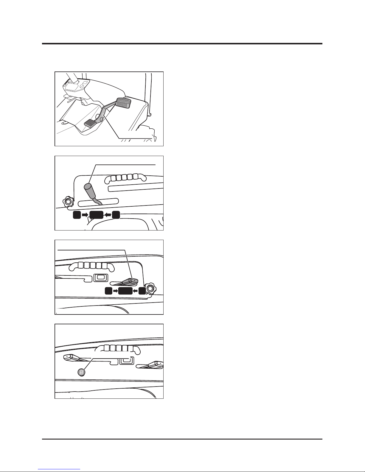
3. Release your foot from the HST pedal.
4. Confirm that the speed change lever is in the
"NEUTRAL" position.
5. Shift the accelerator lever to the intermediate
position between the “LOW” and “HIGH”
positions.
H
INTER.
L
Accelerator lever
Choke lever
6. When the engine is hard to start due to its
cooled state, pull the choke lever.
HST pedal
5317M-0604-010-E
5314M-0602-070-E
5314M-0602-060-E
Page 37
-31-
Operation 6
Parking brake lock lever
Brake pedal
OFF
ON
START
Main switch
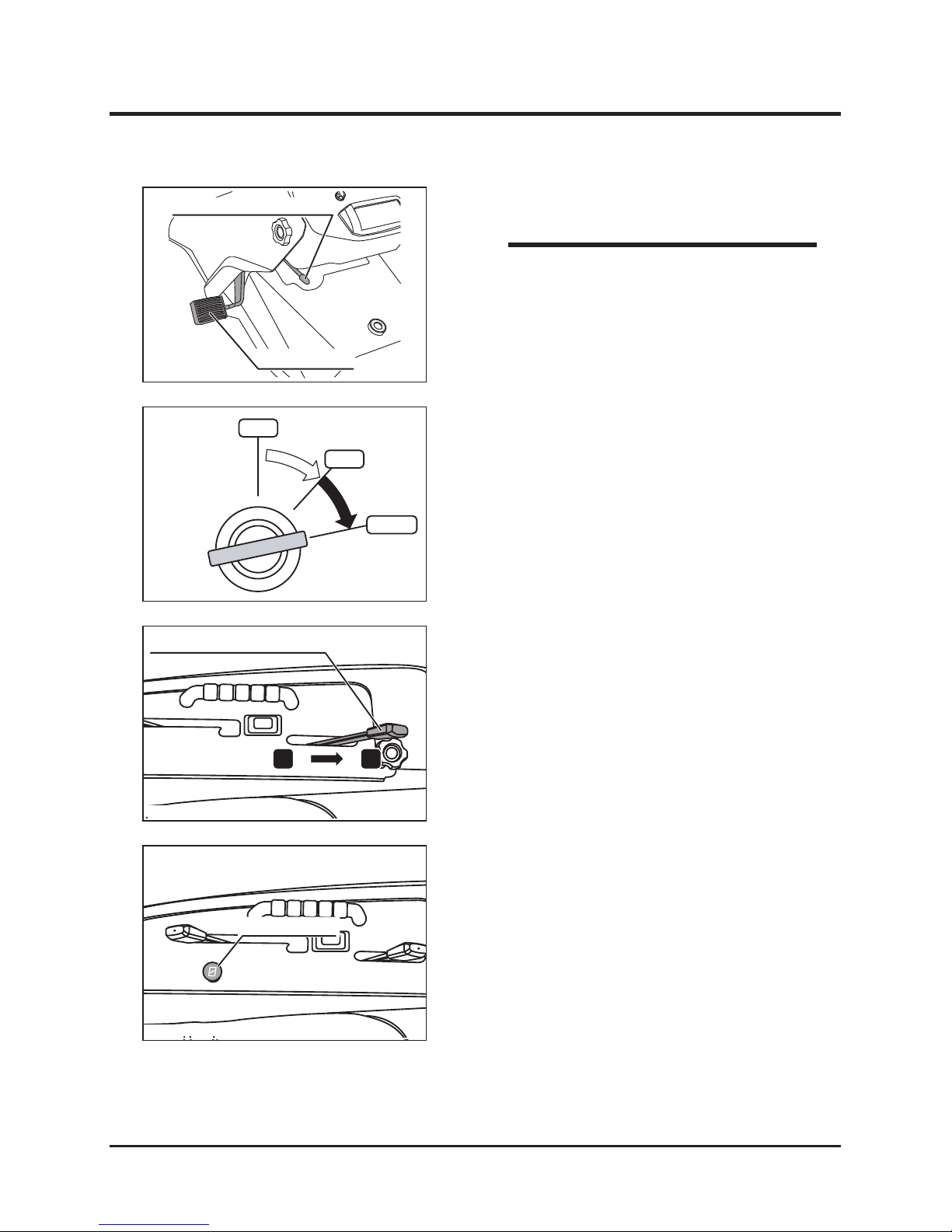
7. Depress the foot brake pedal.
8. Insert the key into the main switch.
9. Turn the main switch to the "START" position to
start the engine.
Accelerator lever
H L
10. Shift the accelerator lever to the “LOW” side.
Choke lever
11. Push the choke lever to the left if necessary to
use.
NOTE
* The engine will start only when the operator
is sitting on the seat and the brake pedal
is depressed. Under these conditions, the
safety switch is disengaged.
5314M-0602-060-E
5314M-0602-010-E
5313M-0602-070-E
5314M-0602-080-E
Page 38
Operation
-32-
6
Parking brake lock lever
Brake pedal
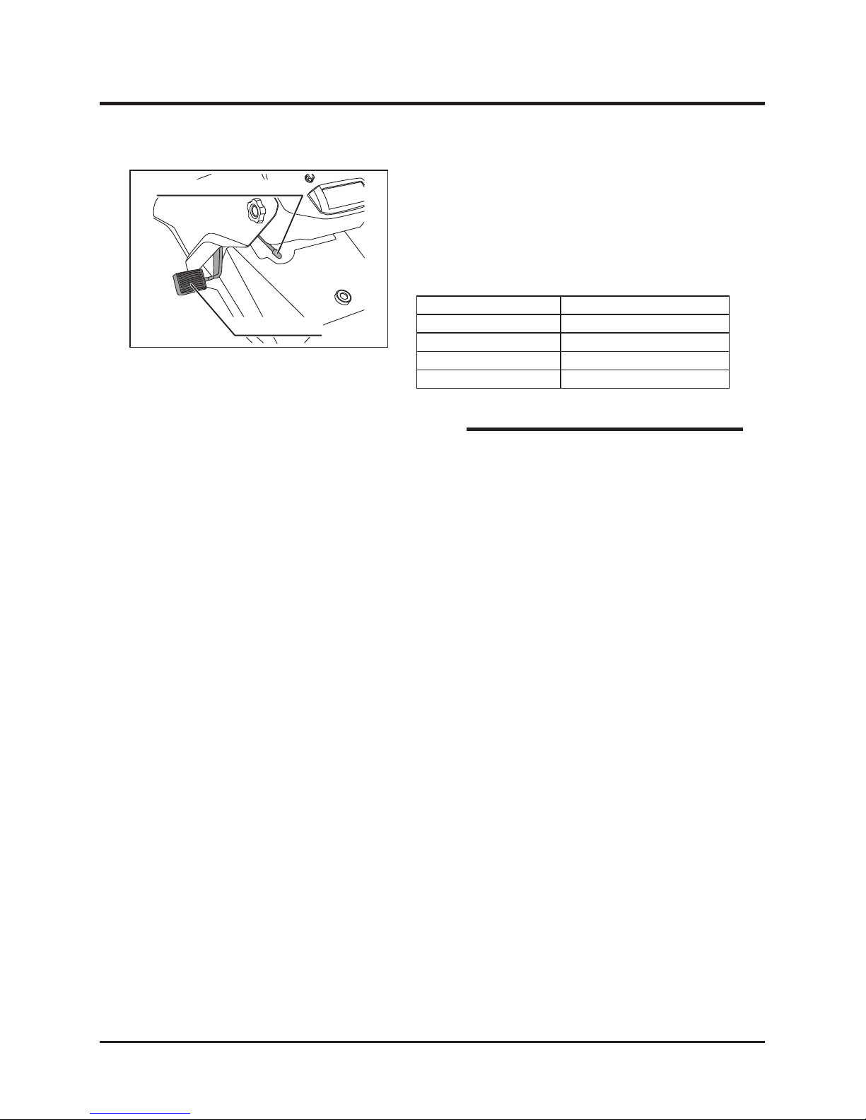
12. Fix the brake pedal in its depress position
using the parking brake lock lever.
13. Warm up engine without loads, referring to the
following table.
* Operate the engine in a moderate mode,
without applying loads for the break-in period
of one week (about 40 to 50 hours) after
purchasing the machine.
NOTE
5314M-0602-010-E
Air temperature
Recommended warming-up time
Over 0°C About 10 minutes
0°C to -10°C 10 to 20 minutes
-10°C to -20°C 20 to 30 minutes
Under -20°C More than 30 minutes
Page 39
-33-
Operation 6
Parking brake lock lever
Brake pedal
H L
Accelerator lever
Operating
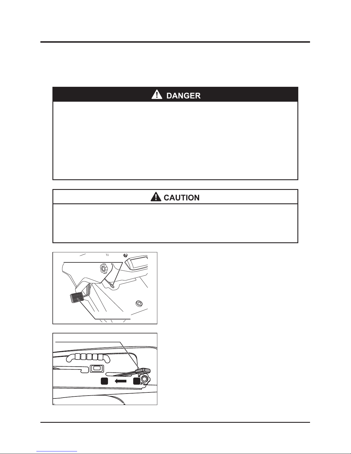
1. Check all directions for safety.
2. Release the parking brake lock lever.
* Do not operate the auxiliary speed change lever when driving the machine.
* Do not turn the main switch to the "OFF" position when driving the machine.
3. Push accelerator lever toward the "HIGH" side
and increase the rotation speed of the engine.
* Keep people away from machine during operation.
* Always check the operation area around machine before starting machine, and
start it machine slowly.
* Always check the operation area around machine before turning machine.
* Avoid sudden starts, accelerations, and turns, to prevent the operator from
being thrown off machine or machine slipping and turning over.
5314M-0602-010-E
5314M-0603-010-E
Page 40
Operation
-34-
6
L
H
N
Speed change lever
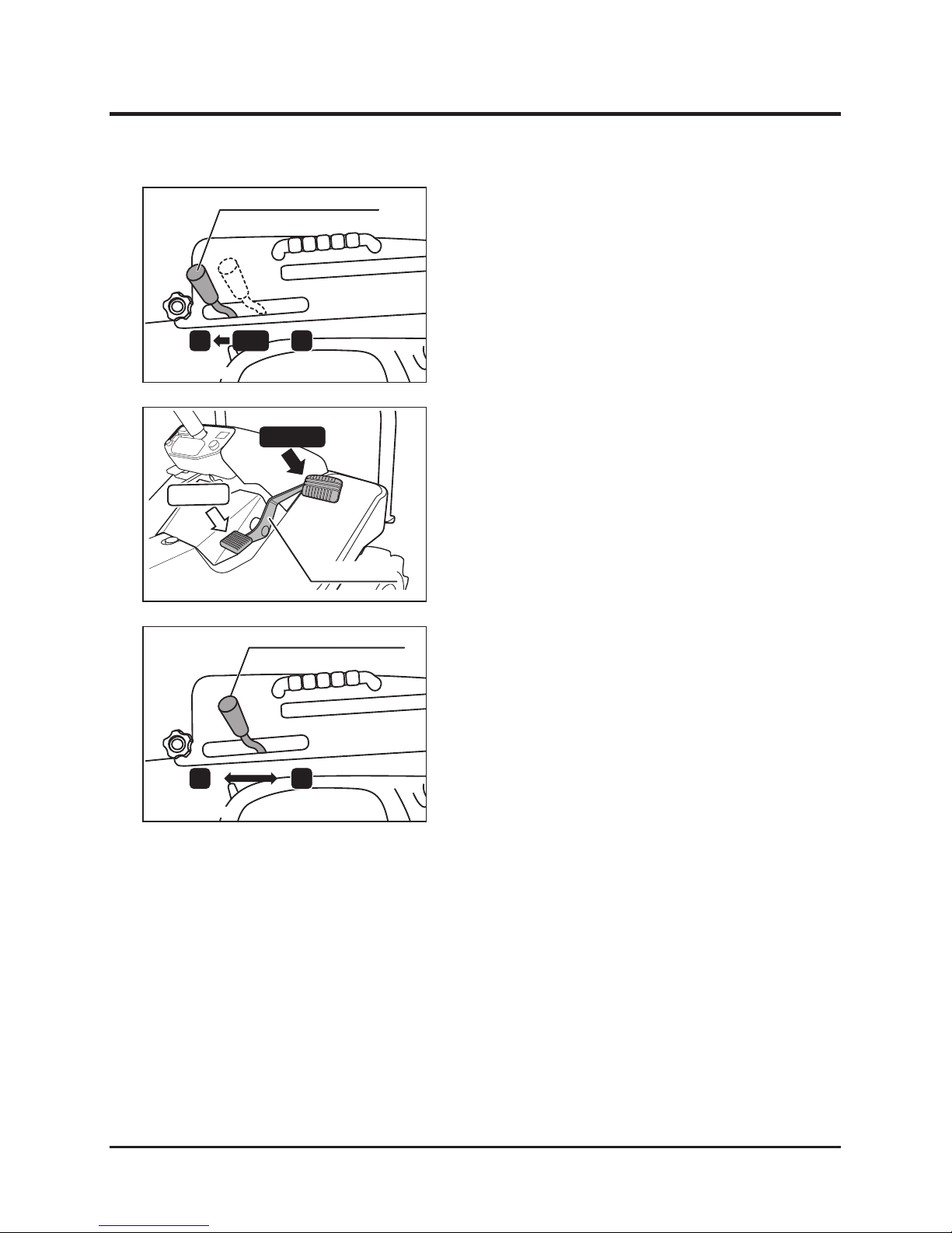
4. Firmly shift the speed change lever to the
“LOW” side.
5. Depress the HST pedal slowly to start the
machine. When driving the machine forward,
depress the front side pedal. When driving
backward, depress the rear side pedal.
Speed change lever
L H
6. Shift the speed change lever to the “LOW”
or “HIGH” sides, according to the working
conditions.
FORWARD
REVERSE
HST pedal
5317M-0604-050-E
5317M-0604-020-E
5317M-0604-060-E
Page 41
-35-
Operation 6
Stopping
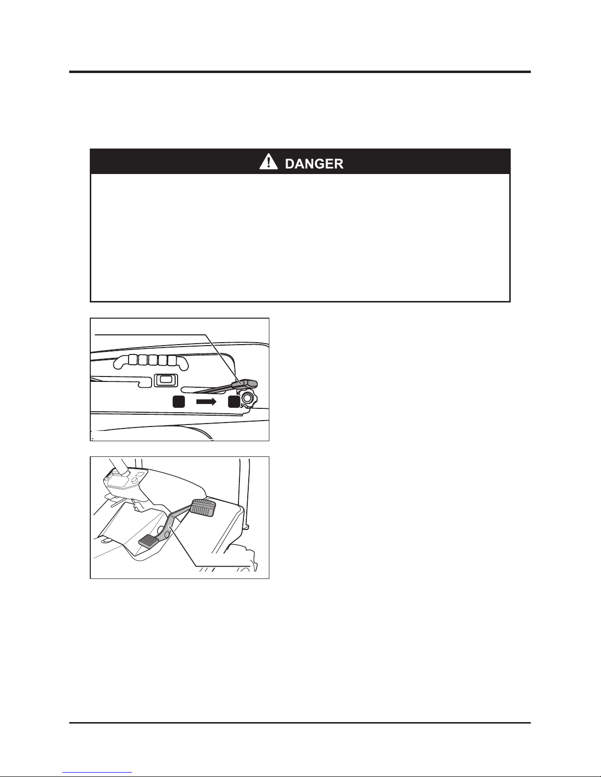
Accelerator lever
H L
1. Shift the accelerator lever to the “LOW” side to
reduce the rotation speed of the engine.
2. Release your foot from the HST pedal.
HST pedal
* Avoid sudden stops to prevent operator from being thrown off the machine and
the machine slipping and turning over.
* Select hard and level ground for stopping or parking the machine. Do not stop
or park the machine in dangerous areas.
* Avoid parking machine on inclined ground. When parking on inclined ground is
necessary, apply the securely parking brake and block the wheels.
5314M-0602-080-E
5317M-0604-010-E
Page 42
Operation
-36-
6
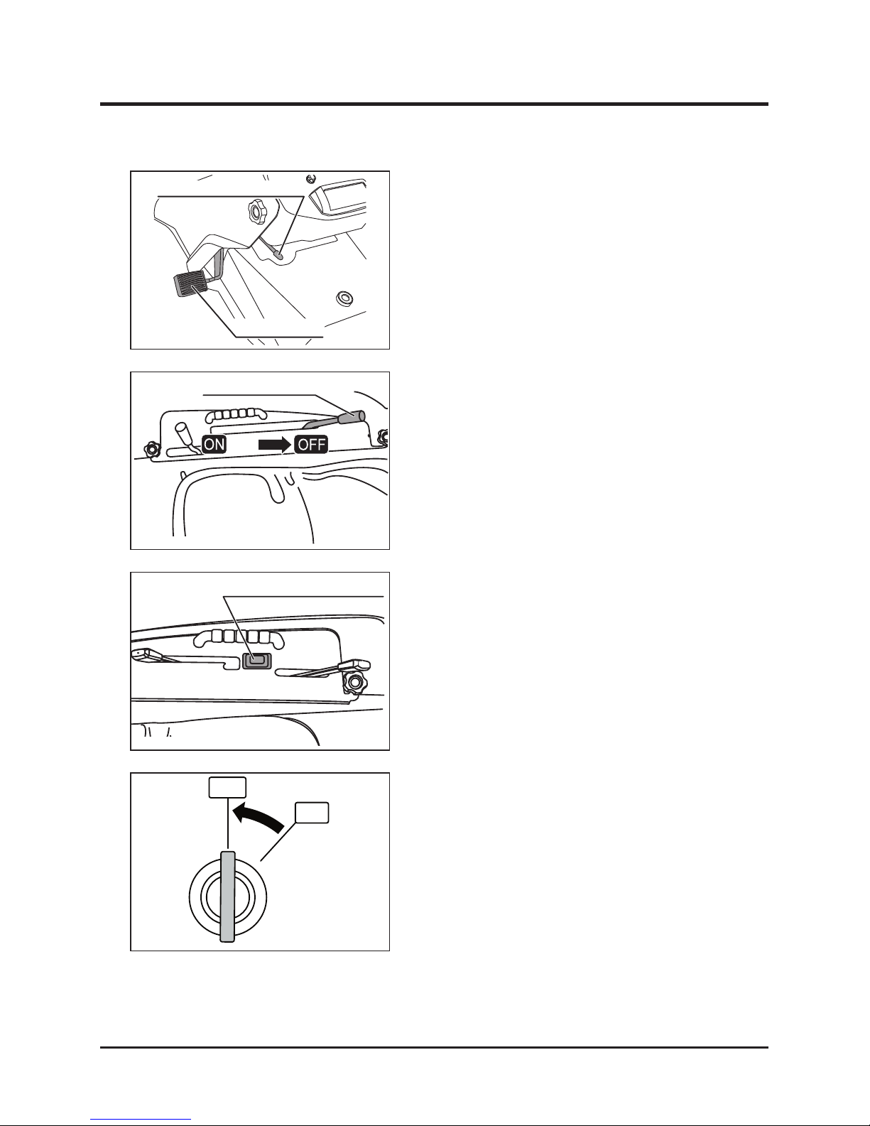
ON
Main switch
OFF
Parking brake lock lever
Brake pedal
3. Depress the brake pedal to firmly stop the
machine.
4. Lock the brake pedal, using the parking brake
lock lever.
5. Confirm that the blade clutch lever is
positioned at “OFF”.
Rotary height adjusting switch
6. Push the "HIGH" side of the rotary height
adjusting switch to raise the blades to the
highest position. (Check the position of the
rotary cutter through the blade height monitor.)
Blade clutch lever
7. Turn the main switch to “OFF” to stop the
engine.
8. Pull out the key from the main switch.
5314M-0602-010-E
5317M-0604-030-E
5314M-0602-030-E
5313M-0604-020-E
Page 43
-37-
Operation 6
How to Perform Work
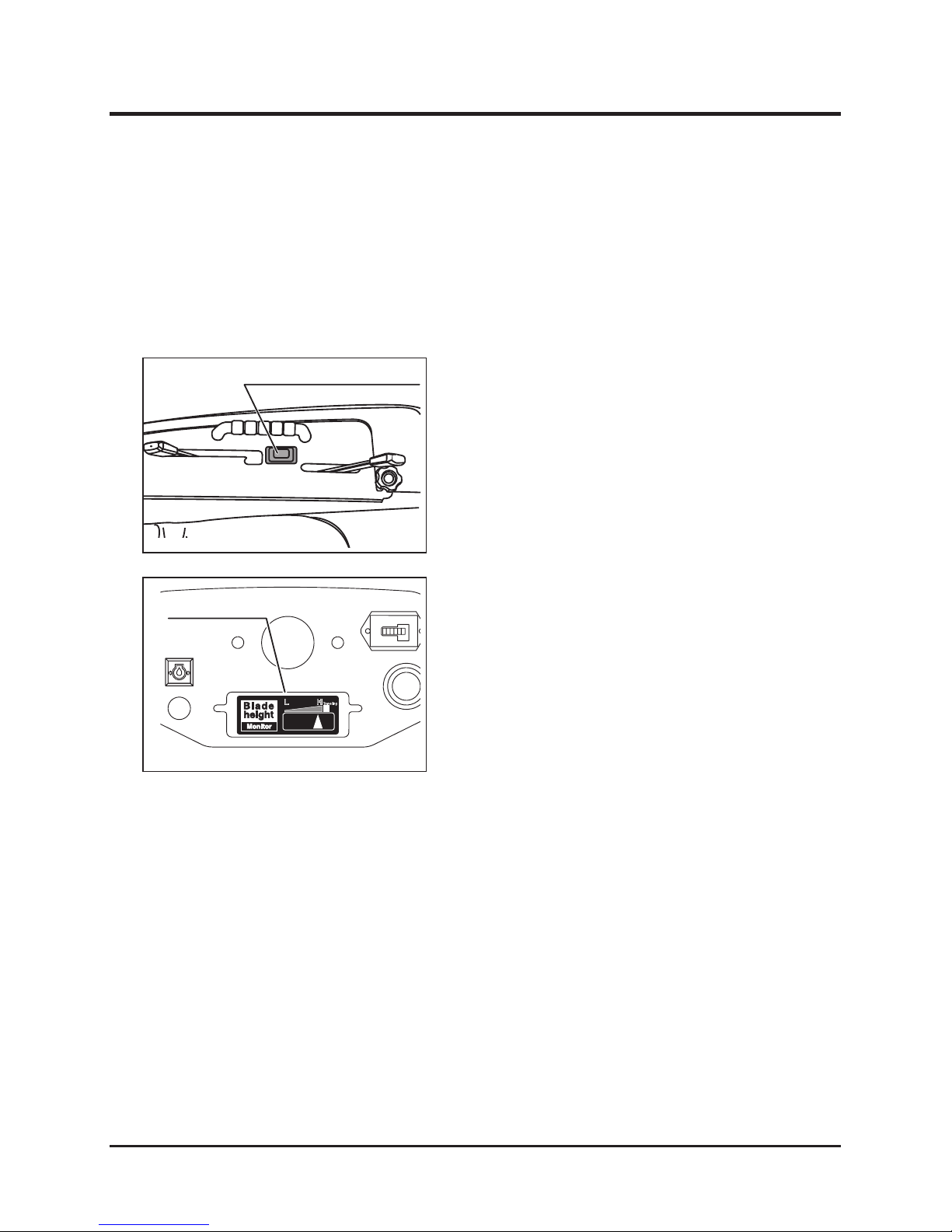
Adjusting Blade Height
1. Adjust cutting height with the blade height
adjusting switch.
2. Confirm the cutting height through the blade
height monitor.
Rotary height adjusting switch
Blade height monitor
Checking Cutting Blades
Before starting work, check the cutting blades. Refer to the procedure in "Check and
replacement of cutting blade" shown on page 69.
5314M-0602-030-E
5317M-0502-040-E
Page 44
Operation
-38-
6
Working Procedure
* Do not insert hands or feet under the cover of the rotating cutting blades.
* Keep people away from machine during cutting work.
* Perform cutting work with caution to avoid to hurting people and animals and
damaging crops, buildings, automobiles, and other objects or structures with
stones or other object thrown by the machine.
* Perform cutting work only while travelling forward. Cutting while travelling
backward may cause damage to surrounding area due to thrown stones or
other objects.
* Drive the machine around obstacles on the left side of the machine to avoid
thrown material rebanding off objects and striking machine.
* Perform cutting work with cutter cover closed to prevent thrown material
from damaging the surrounding area. Apply the cutting blade clutch just
before starting cutting work. Always keep clutch in "STOP" position unless
performing cutting work.
* Avoid perform cutting work close to sides of ditches or banks, to prevent
machine turning over due to collapsing shoulders. Use extra care when
operating on ground affected by recent rainfall or earthquakes.
* Always check holes and obstacles in the working area before performing
cutting work. Use care when performing work near holes and obstacles.
* Avoid performing cutting work at an inclined area steeper than 25°.
* Avoid turning the machine on inclined areas to prevent operator imbalance.
* Avoid performing cutting work in slippery areas.
* Immediately replace broken cutting blades. Broken blades may unbalance the
rotary blade and cause vibrations and failure.
Page 45
-39-
Operation 6
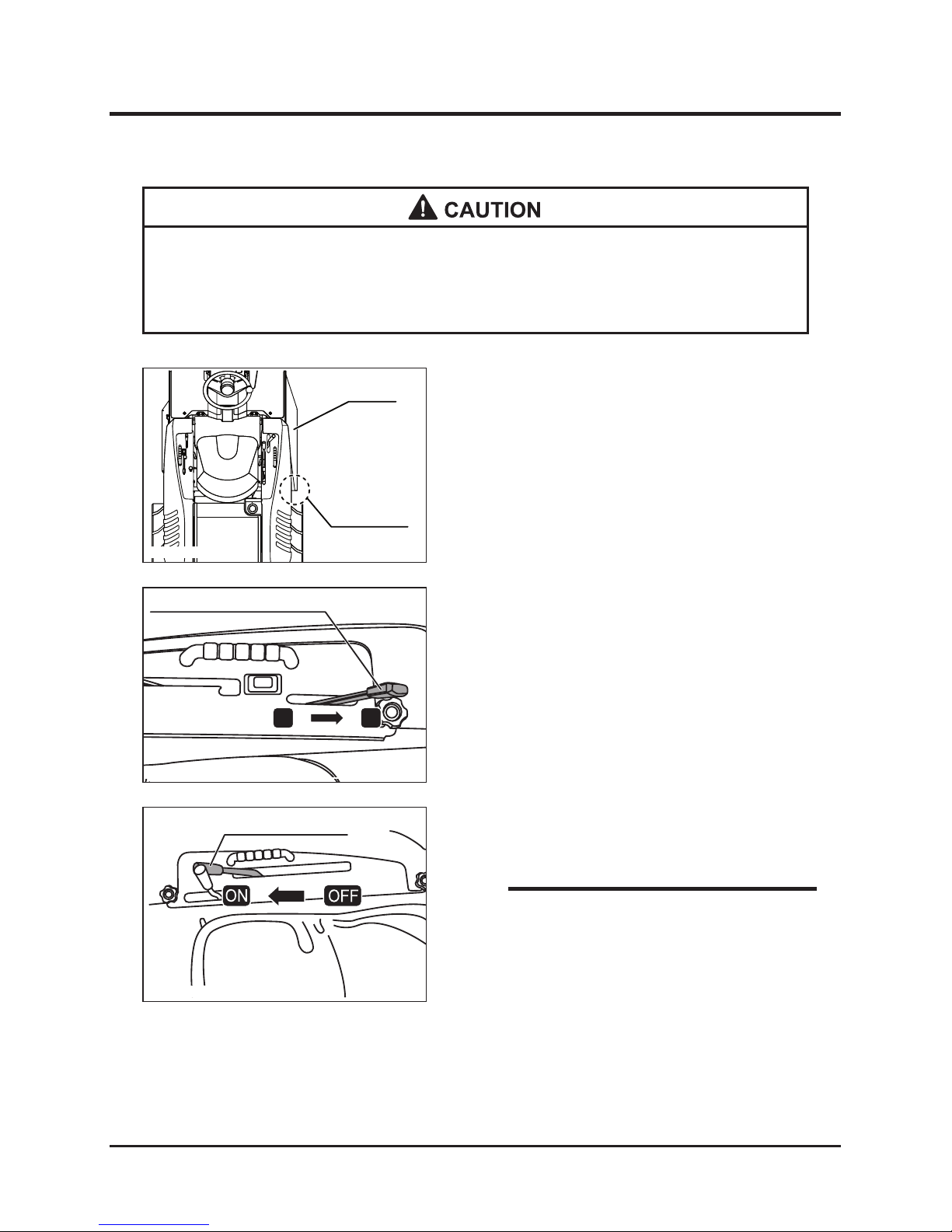
Cover
Grass chute
1. Confirm that the grass chute cover is closed.
Accelerator lever
H L
Blade clutch lever
2. Start the engine and shift the engine control
lever to the intermediate position between
"HIGH" and "LOW".
3. Shift the blade clutch lever slowly to “ON”.
NOTE
* When the rotary blade is at the highest
position, the cutting blade clutch cannot be
shifted to “ON”. Shift the blade clutch after
slightly lowering the rotary cutter.
5314M-0608-020-E
5314M-0602-080-E
5317M-0605-010-E
* Immediately stop the engine to remove any foreign matter caught in the cutting
blades. Foreign matter may unbalance the rotary blade and cause vibrations
and failure.
Page 46
Operation
-40-
6
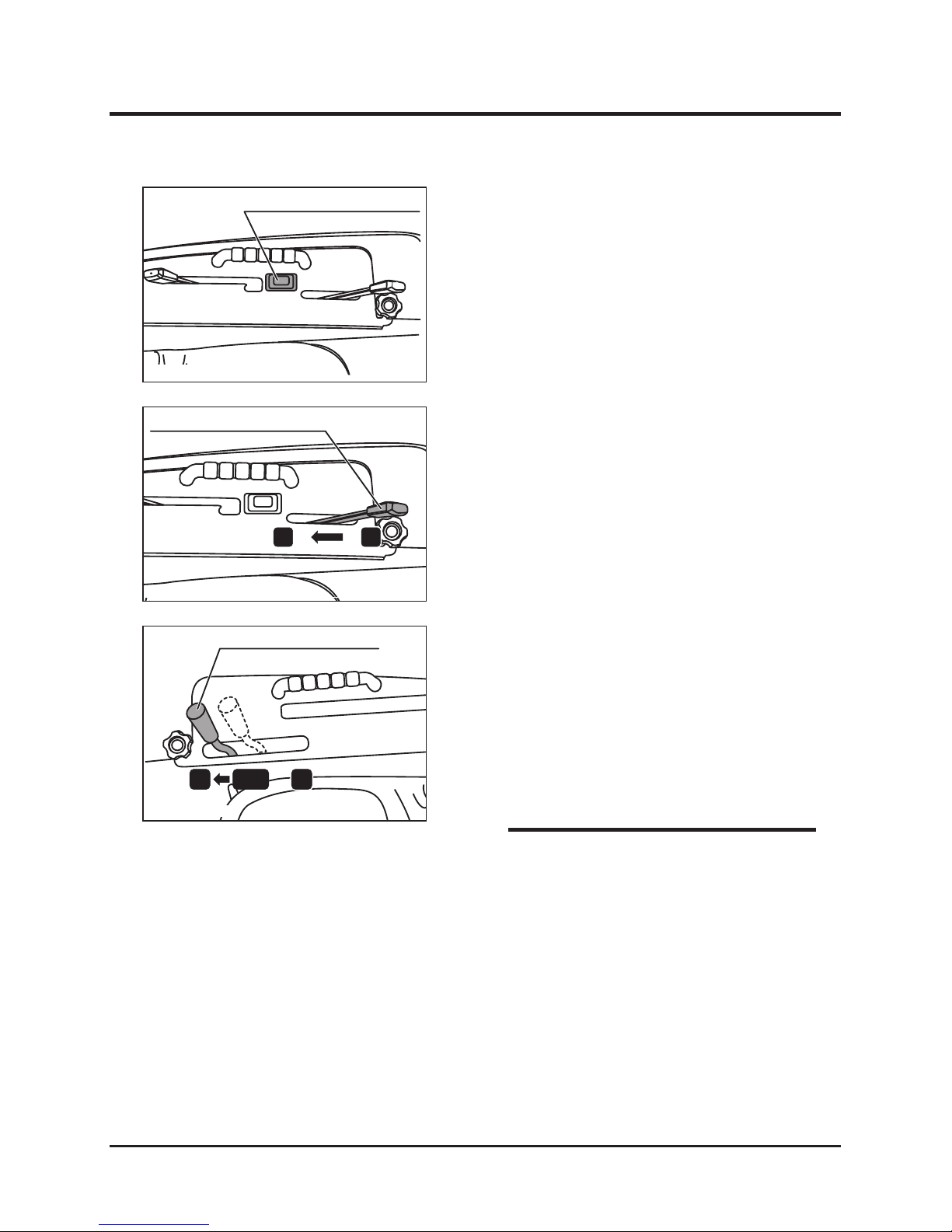
Rotary height adjusting switch
NOTE
* When first using machine after purchasing,
use on level area and slowly perform cutting
work in straight, slightly overlapping lines.
4. If necessary, change the blade height by
adjusting the rotary height adjusting switch.
H L
Accelerator lever
5. Shift the accelerator lever to “HIGH” and
increase the rotation speed of the engine.
L
H
N
Speed change lever
6. Shift the auxiliary speed change lever to
"LOW", and start the cutting work at low
running speed. (Adjust the running speed
according to work conditions.)
7. When the working load is heavy (due to cutting
a large amount of material), reduce running
speed or raise cutting height and cut two
times.
5314M-0603-010-E
5317M-0604-050-E
5314M-0602-030-E
Page 47
-41-
Operation 6
* When loading and unloading the machine onto or off a truck, follow these
procedures:
* Keep people away from the machine, truck, and running boards while loading
or unloading the machine.
* Do not turn on the running boards. The machine may drop off the running
boards.
* Drive slowly up or down the running boards.
* Beware of tipping when machine crosses from running boards into truck bed.
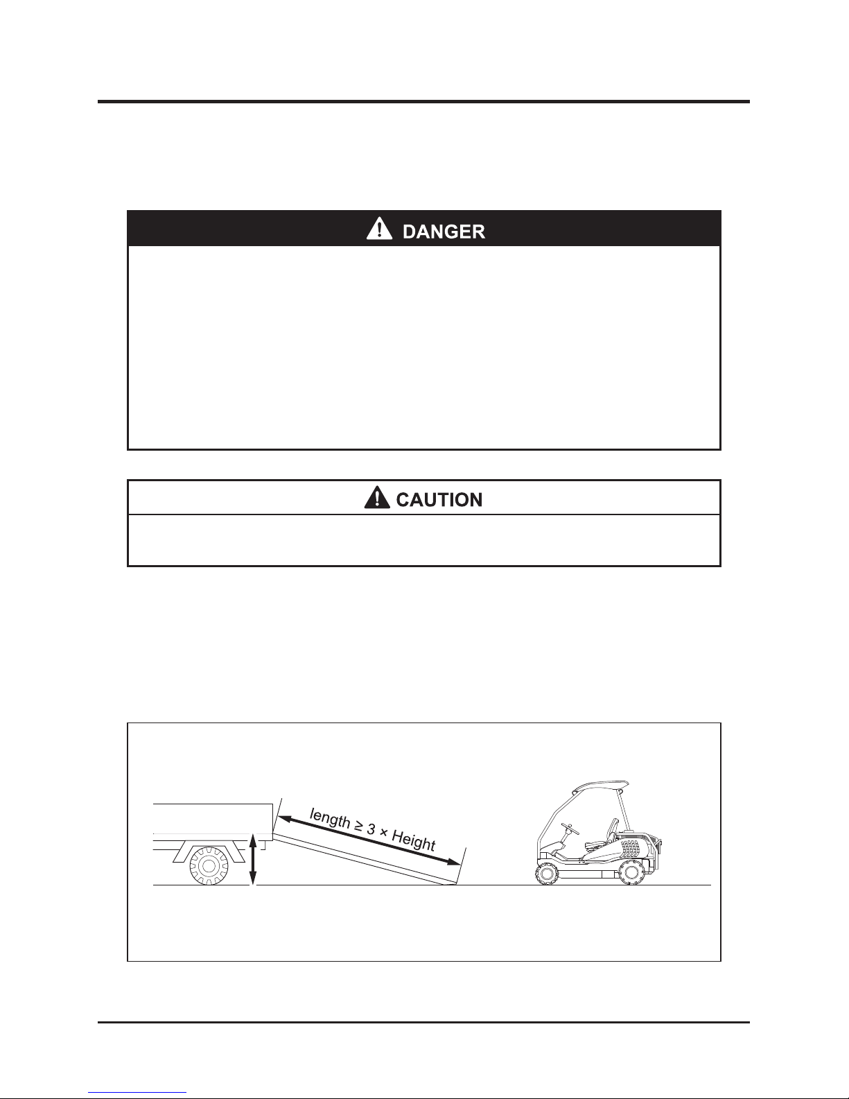
1. Use running boards with enough strength to hold both machine and driver's weight, each
board’s width at least twice the width of machine’s tire width, length more than three times
longer than truck loading body height, and abrasive surface for traction. Place the boards
as shown below so that the boards will not shift positions when the machine rides on
them.
2. Securely hook the running boards to truck so boards are flush with truck's loading bed.
Transportation
Loading
Height
5317M-0606-010-E
Page 48
Operation
-42-
6
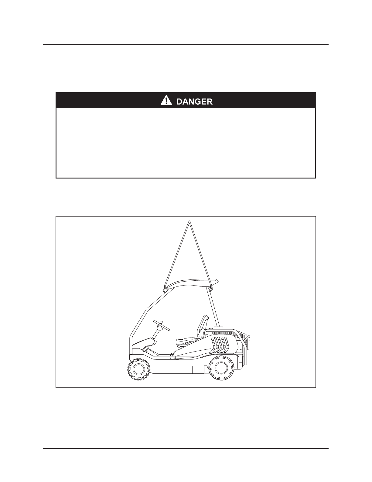
* Crane operations and slinging work should be performed by qualified
operators.
* Use lifting wire ropes and shackles with sufficient strength to hold the weight of
the machine.
* Carefully consider the machine’s center of gravity and balance while lifting.
Lifting by Crane
Use installed four hoisting lugs to securely sling the machine and maintain horizontal balance
when lifting.
5317M-0606-020
machine weight : 490kg
Page 49
-43-
Operation 6
Emergency Transferring
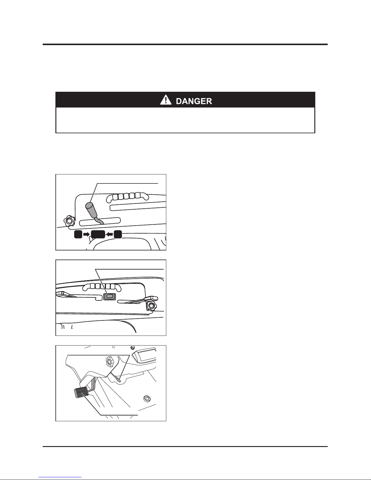
When the machine cannot be moved by normal means due to engine trouble or other factors,
transfer it using this procedure.
Speed change lever
L
H
N
1. Shift the speed change lever to “NEUTRAL”.
* Do not use this method to transfer the machine from an inclined area.
Rotary height adjusting switch
2. Push the “HIGH” side of the rotary height
adjusting switch to raise the rotary cutter to the
highest position.
Parking brake lock lever
Brake pedal
3. Release the parking brake lock lever, and then
transfer the machine.
5314M-0604-040-E
5314M-0602-010-E
5314M-0602-030-E
Page 50
Maintenance
-44-
7
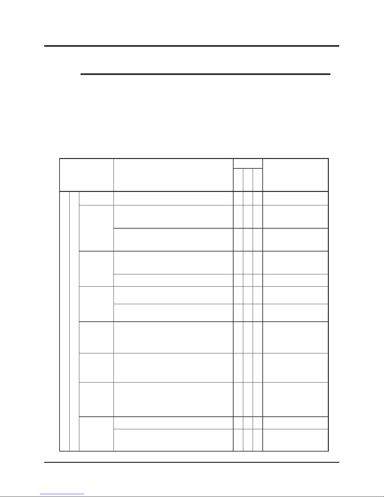
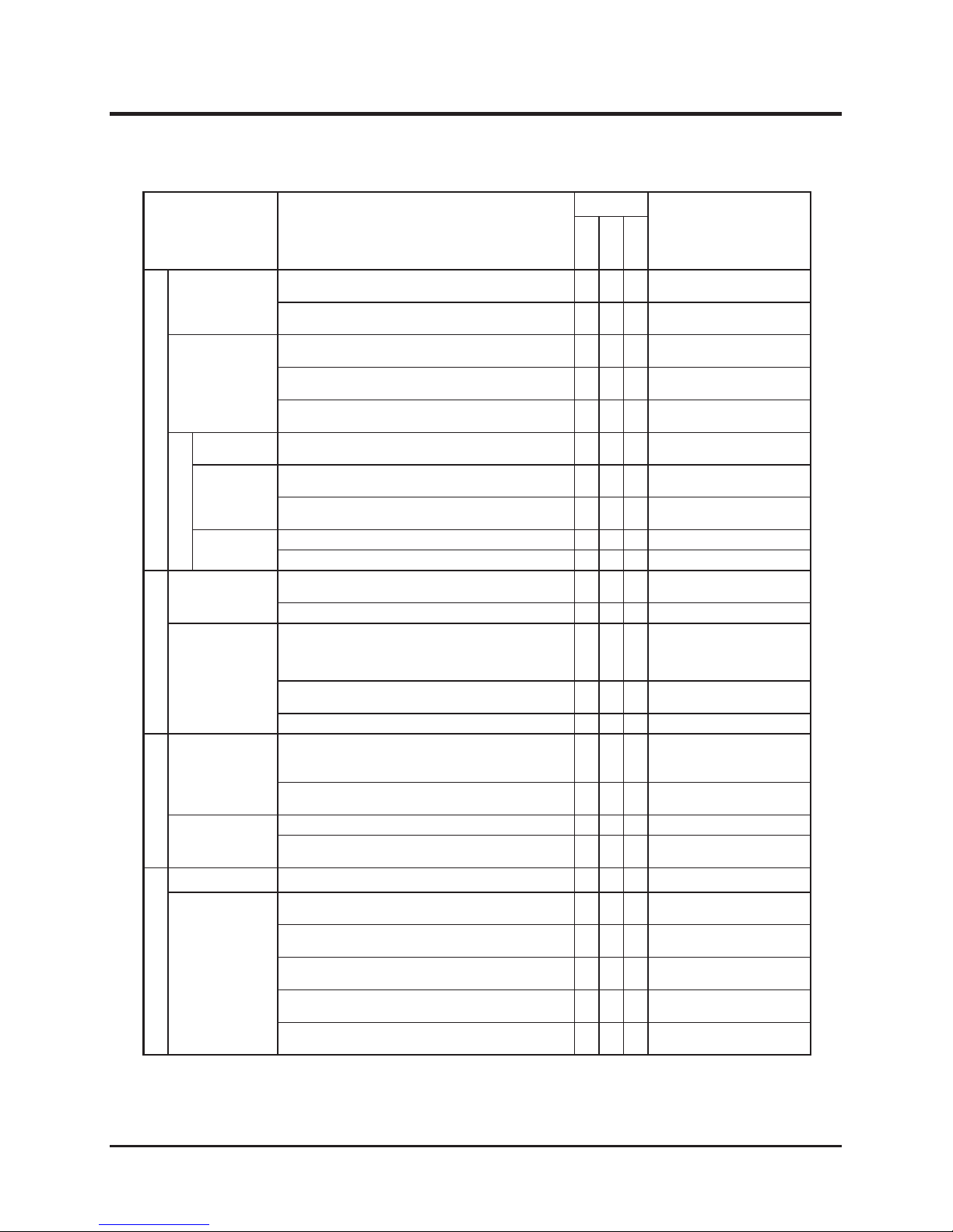
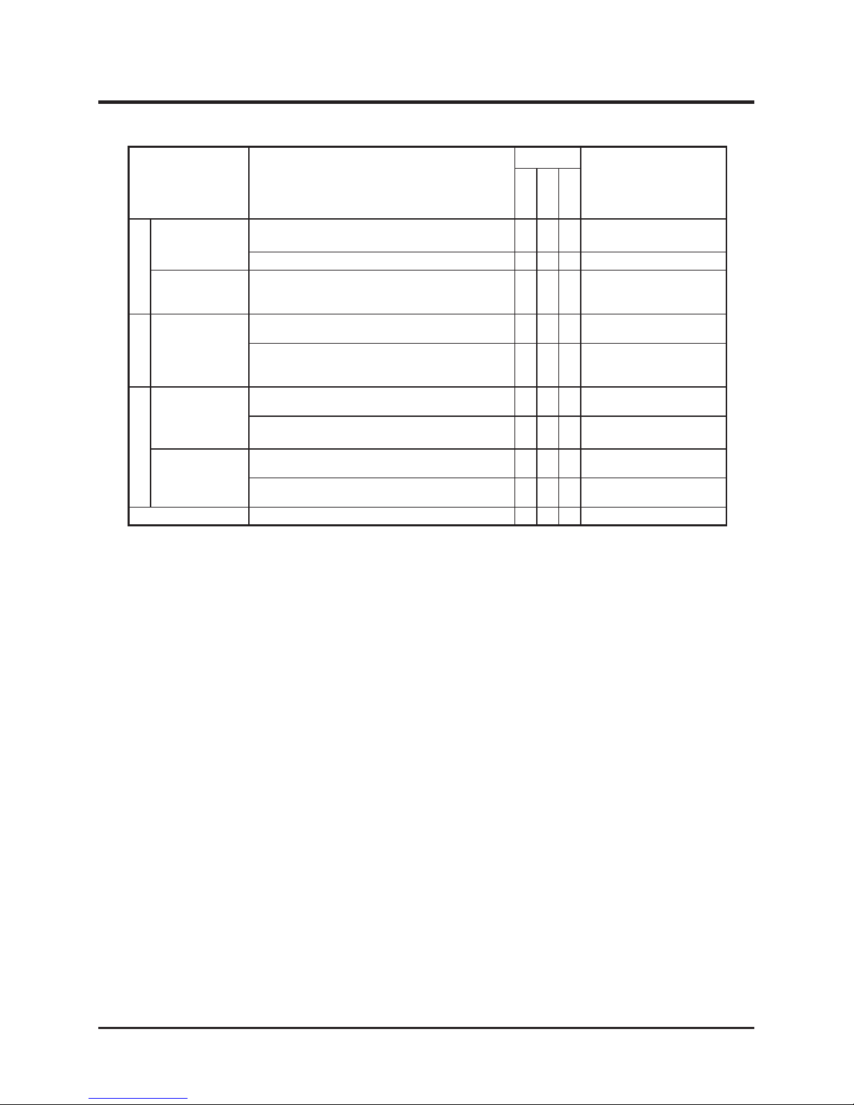
Periodic Check Sheet
* Neglecting inspections and maintenance may cause accidents. To keep the machine
safely functioning, periodically perform inspection and maintenance according to the
following table.
* Maintenance schedule as per following table.
* Checking items in the following table may requiring special knowledge, tools, or
instruments. When you cannot independently perform checks yourself, contact the
dealer from whom you purchased the machine.
NOTE
Item Action
Timing
Remarks
Per-operation
Monthly
Yearly
Engine
Body
Starting
The engine should start easily without irregular
noise.
○ ○ ○
Engine speed
The rotation speeds at the idling and maximum
rotation at no-load should meet the specified
values, respectively, and both rotation speeds
should be constant.
○ ○
Please contact your
Canycom distributor
When accelerating the engine, the movement
of the accelerating lever should be smooth, the
engine should not stop, and knocking should not
occur.
○ ○ ○
Exhaust
When the engine is sufficiently warmed up, the
colors and discharging sound of exhaust gas
should be normal from idling through maximum
rotation speeds.
○ ○ ○
There should be no leakage in the exhaust pipe
and muffler.
○ ○
Air cleaner
There should be neither cracks nor deformations
in the air cleaner casing and no looseness in the
connection pipe.
○ ○
There should be neither excess dirt nor damage
in both urethane form and paper filter elements. ○
Cleaning / Replacement
(see page 52)
Tightening
There should be no looseness in the bolts and
nuts of the tightening parts of the cylinder head
and manifold.
○
* This check can be omitted if neither gas nor
water leaks are found in those parts.
Valve
clearance
The clearance of the valve should be normal.
○
Please contact your
Canycom distributor
* This check can be omitted when there is no
irregular noise due to the abnormal clearance
of the valve and the engine runs smoothly.
Compressing
pressure
The pressure should be normal.
○
Please contact your
Canycom distributor
* This check can be omitted when there is no
irregularity in both the rotating states and
in exhaust gas conditions during idling and
accelerating.
Engine
mount
There should be neither cracks nor deformations
in the engine base.
○
There should be neither looseness in nor missing
mounting bolts and nuts.
○
Maintenance
Page 51
-45-
Maintenance 7
Item Action
Timing
Remarks
Per-operation
Monthly
Yearly
Engine
Lubricating
system
The amount of oil should be proper and no
noticeable dirt should be found in oil.
○ ○ ○
Action / Replacement
(see page 52)
There should be no noticeable oil leak in the
head cover, oil pan, and oil tubes.
○ ○ ○
Fuel system
There should be no noticeable fuel leak in the
fuel tank, injection pump, and fuel tubing.
○ ○ ○
There should be neither damage nor
deterioration in the fuel hose.
○ ○ ○
There should be neither noticeable dirt nor
clogging in the fuel filter.
○ ○
Cleaning (see page 56)
Electrical
Ignition plug
There should be neither wear nor carbon
deposits on the electrodes.
○ ○ Cleaning (see page 53)
Battery
The amount of electrolyte should be kept in the
specified range.
○ ○
There should be neither looseness nor noticeable
corrosion on the terminals.
○ ○
Wiring
harness
There should be no looseness in the connections.
○ ○
There should be no damage in the wiring.
○ ○
Power train
V-belts
There should be neither visual damage nor
adhesion of grease to belts.
○ ○
The tension of V-belts should be proper.
○ ○
Transmission
The transmission should operate normally in
turning and forward and backward driving of the
machine, and there should be neither irregular
noise nor overheating.
○ ○ ○
The amount of oil in the casing should be proper
and no noticeable dirt should be found in oil.
○ ○
There should be no oil leak around the casing.
○ ○
Speed adjustment
Speed change
lever
The lever should reliably shift to every speed
changing position and the machine should
properly responce.
○ ○ ○
There should be neither looseness nor rattle in
the lever-mounting portion.
○ ○ ○
HSTpedal
The pedal should reliably operate.
○ ○ ○
There should be neither looseness nor rattle in
the pedal-mounting portion.
○ ○ ○
Drive system
Steering wheel
The steering wheel should reliably be turned.
○ ○ ○
Tire, wheel
The tire pressures should match specified values.
○ ○
The tires and wheels should not have any crack,
damage, nor unbalances.
○ ○ ○
Metal pieces, stones or foreign matter should not
be caught in tire grooves.
○ ○ ○
There should be neither looseness of nor missing
wheel bolts and hub nuts.
○ ○ ○
There should not be any rattles, irregular noises,
or overheating in the wheel bearings.
○ ○
Page 52
Maintenance
-46-
7
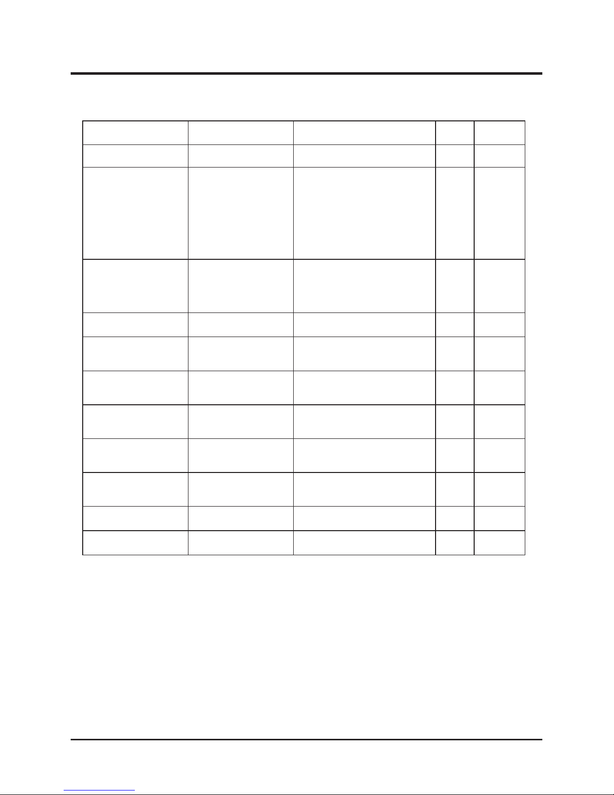
Item Action
Timing
Remarks
Per-operation
Monthly
Yearly
Brake
Brake
Brake action should stop the machine under
normal driving conditions.
○ ○
The play of the pedal should be proper.
○ ○
Rod, link, and
wires
There should be no damage in the rods, links,
or wires, and no looseness in their mounting
portions.
○ ○ ○
Lamp system
Head lamp
Lighting should be normal.
○ ○ ○
There should be no damage in the lenses, and no
water inside lenses.
○ ○
Rotary
Cutter blade
Blades should have cracks, damage, or
noticeable wear.
○ ○ ○
Blade-mounting bolts should not have cracks,
damage, or noticeable wear.
○ ○ ○
Cutter blade
cover
There should not be cracks nor damage in the
blade cover.
○ ○ ○
Rubber curtain should not be damaged or
missing.
○ ○ ○
Horn
The operation should be normal.
○
Page 53
-47-
Maintenance 7
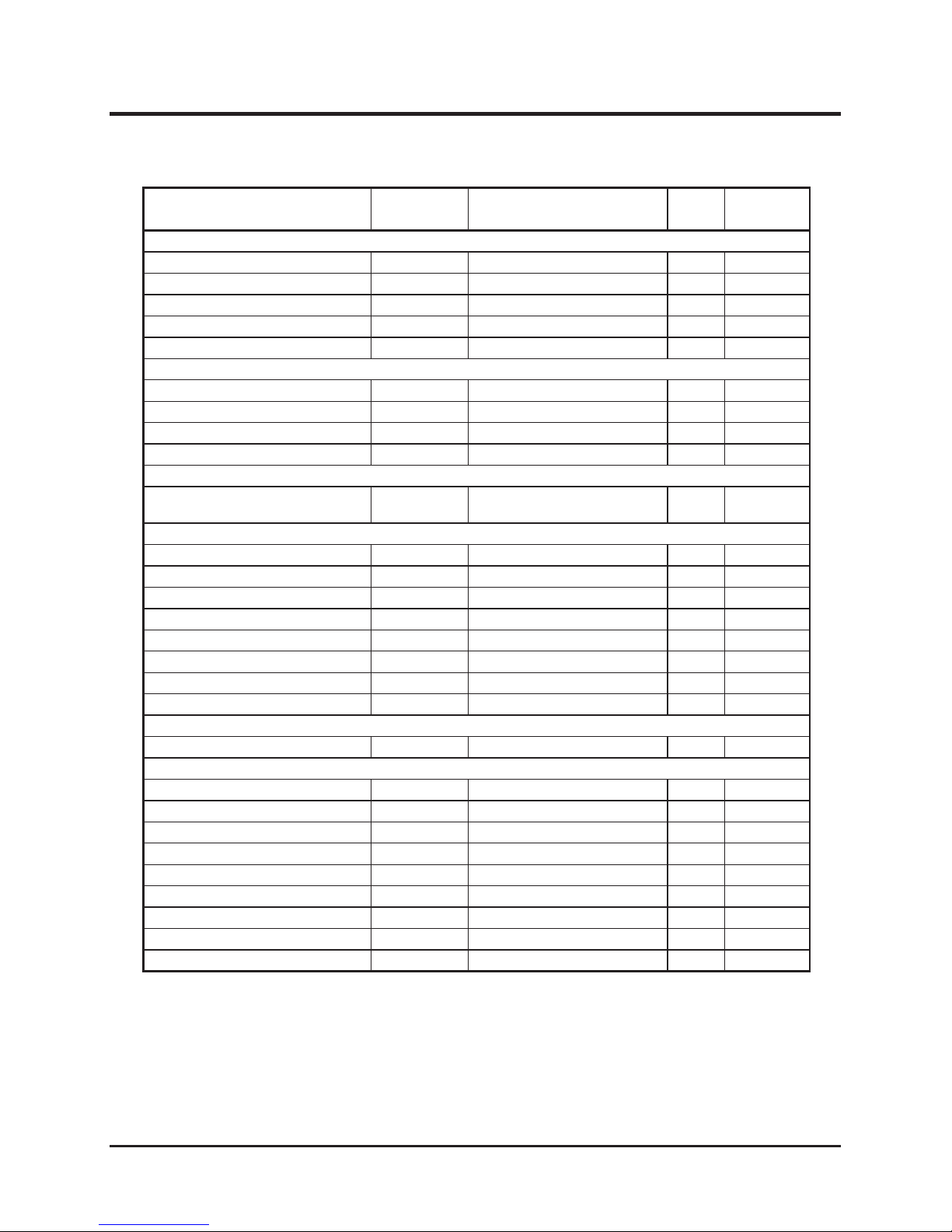
Fuel / Grease / Lubricant / Fluid Chart
Item Timing Recommendation
Amount
Reference
page
Fuel
As necessary. Gasoline
30.0 liter
See page
17
Engine oil
Add : Check daily and
add as necessary.
Replace :
1st time after 8
operating hours
2nd time and later :
every 50 operating
hours (about every
week)
Engine oil
API class : SE higher #20~#30
SAE class: 10W-30
1.5 liter
See page
19
Transmission oil
1st time after 50
operating hours
2nd time and later :
every 500 operating
hours
Gear oil
API class GL4 or 5
SAE class #80
2.0 liter
See page
60
HST oil
Engine oil
SAE class: 20W-50
3.0 liter
See page
57
Oil for the cutter blade
counter case
-
Gear oil
API class GL4 or 5
SAE class #80
0.39 liter
Oil for the cutter blade
upper case
-
Gear oil
API class GL4 or 5
SAE class #80
0.83 liter
Front differential gear oil
(center)
-
Gear oil
API class GL4 or 5
SAE class #80
0.36 liter
See page
61
Front knuckle gear oil
(both sides)
-
Gear oil
API class GL4 or 5
SAE class #80
Each
0.05 liter
See page
61
Lubrication
Every six months. Gear oil
API class GL4 or 5
SAE class #80
-
See pages
20, 73
Grease
Every six months.
Chassis grease
-
See pages
20, 73
Battery fluid
Check every month and
add as necessary.
Distilled water
-
See page
64
Page 54
Maintenance
-48-
7
Consumable (Replacement Parts) Chart
Item Part No. Replacement Quantity Reference
Engine
Engine oil filter cartridge - Replace if defective 1 See page 51
Paper element - Replace if defective 1 See page 52
Foam element - Replace if defective 1 See page 52
Throttle wire 53100102000 Replace if defective 1
Choke wire 53100105000 Replace if defective 1
Fuel system
Fuel filter - Replace if defective 1 See page 56
Hose (fuel tank to adapter) 53170324000 Every 2 years 1
Hose (fuel tank to adapter) 53170326000 Every 2 years 2
Hose (fuel tank connection) 53170321000 Every 2 years 1
Hydraulic system
Element Assembly 53102053100 Replace replacing HST oil. 1
Driving system
Driving V-belt 08521300040 Replace if defective 1 See page 62
Brake lining 72072157100 Replace if defective 1 set
Brake wire 53103315000 Replace if defective 1
Differential lock wire 53104085000 Replace if defective 1
Tire assembly Front wheel(R) 53142201000 Replace if defective 1 See page 63
Tire assembly Front wheel(L) 53142205000 Replace if defective 1 See page 63
Tire assembly Rear wheel(R) 53142301000 Replace if defective 1 See page 63
Tire assembly Rear wheel(L) 53142302000 Replace if defective 1 See page 63
Electrical equipment
Battery 37053901000 Replace if defective 1
Cutting unit
Cutter blade set 53096201000 Replace if defective 2 See page 70
Blade tool 53139004000 Cutter Blade replacement tool 1
Bilt set 53109906000 Replace if defective 2 See page 70
Brake lever 53104301000 Replace if defective 1 See page 70
Cutter blade stay 53044201000 Replace if defective 1 See page 70
Rotary V-belt 08521600037 Replace if defective 2
Cutter blade clutch wire 53102406000 Replace if defective 1
Cutter brake wire 53104306000 Replace if defective 1
Wire(for the blade height monitor) 53104085000 Replace if defective 1
Rubber parts such as hydraulic hoses will deteriorate even when not used. Replace them
every 2 years, or whenever damaged.
Page 55
-49-
Maintenance 7
Engine
* Always stop engine before performing maintenance.
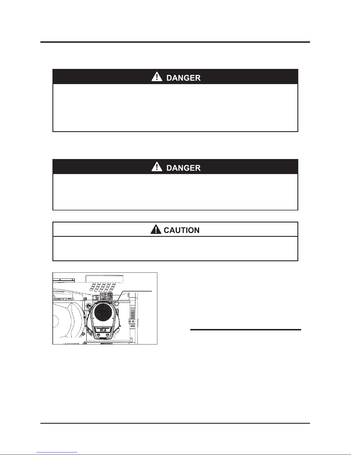
* Perform maintenance after engine has cooled to reduce risk of burns from high
engine temperatures.
Inspecting, Adding, and Replacing Engine Oil
* Carefully add engine oil to reduce risk of causing engine failure.
* Allow oil to cool before inspecting, adding or replacing to reduce risk of burns.
* Properly dispose of waste oil after removing from engine.
1. Park the machine on level ground.
2. Open the engine cover.
3. Pull out the oil filler cap (with oil level gage).
Inspection
NOTE
Filler cap
5310M-0601-040-E
* Check the amount of oil before the engine is
started or at least 10 minutes or more after
the engine has stopped. Immediately after
the engine is stopped, oil still remains in parts
of the engine, so oil checks are not accurate.
Page 56
Maintenance
-50-
7
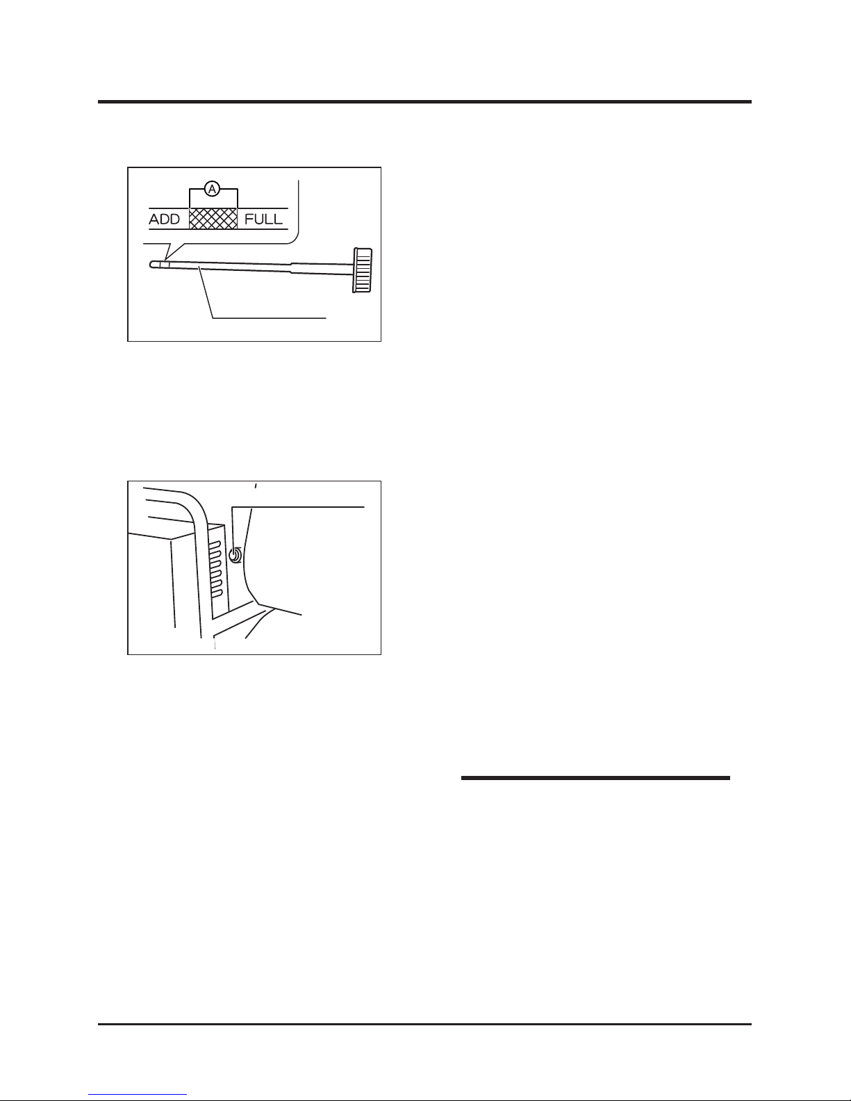
4. Add the specified engine oil when the oil level
is lower than range indicated by "A" on the oil
level gage.
5. Replace the present engine oil with new
oil if present oil is noticeably dirty or has
deteriorated into poor viscosity.
Oil level gauge
5310M-0601-050-E
Oil drain plug
1. Position a vessel suitable for receiving the
engine oil under the oil drain plug.
2. Remove the drain plug and drain the engine oil
into the vessel.
3. Securely replace oil drain plug.
4. Remove the cap from the oil filler port.
5. Add fresh specified engine oil to the oil filler
port.
6. Confirm that the new oil level is within range
indicated by “A” on the oil level gage.
7. Securely attach the cap to the oil filler port.
Replacing Oil
Adding Oil
1. Add the specified engine oil to the oil filler port.
2. Confirm that the oil level is within range
indicated by “A” on the oil level gage.
3. Securely attach the cap to the oil filler port.
* Specified engine oil: See page 47
* Amount of engine oil: See page 47
NOTE
5310M-0701-010-E
Page 57
-51-
Maintenance 7
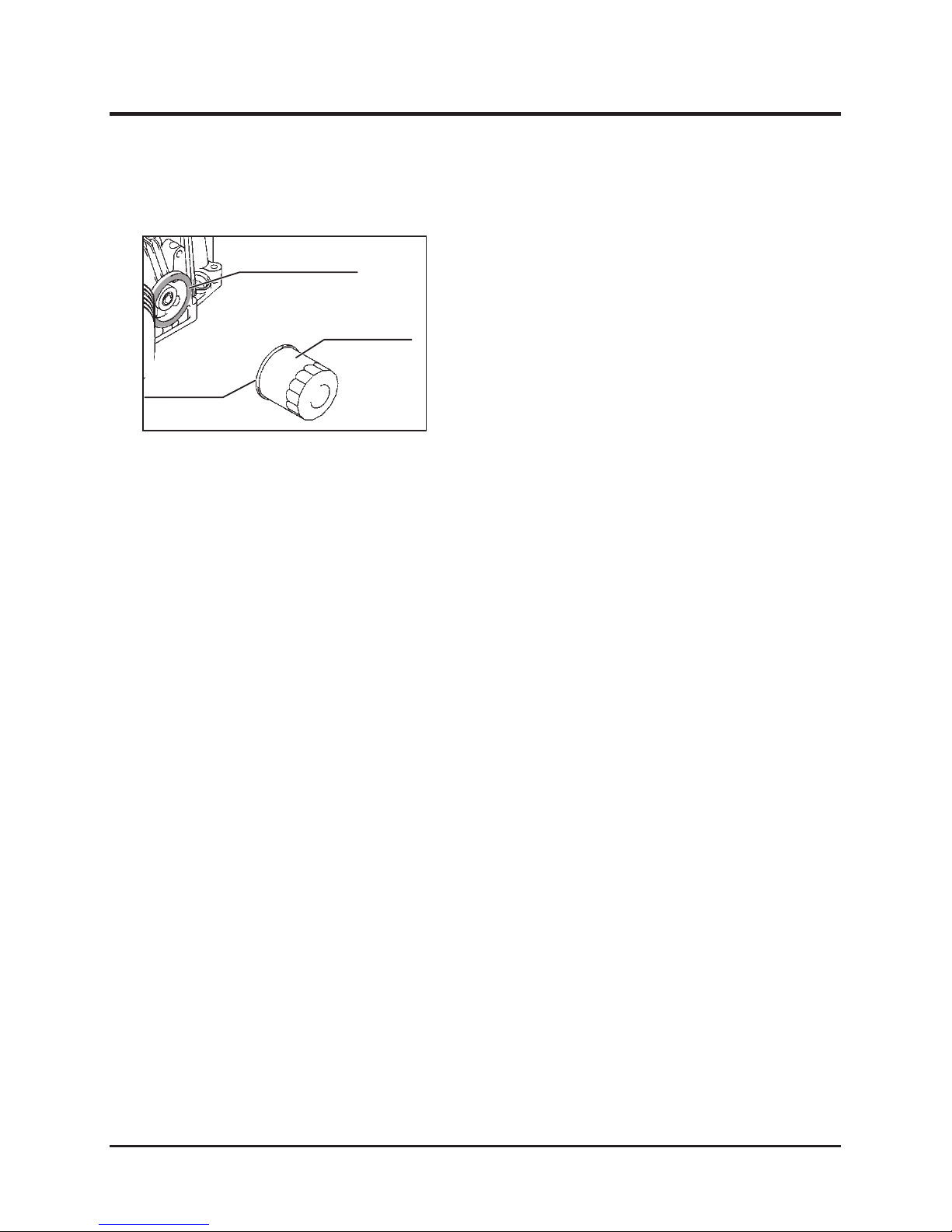
Mating surface “B”
Sealing
surface “A”
Filter cartrige
1. Drain the engine oil.
2. Remove the oil filter cartridge, using an oil filter
wrench.
3. Clean the mating surface “B” for mounting the
filter cartridge to the engine.
4. Apply a film of new oil to the sealing surface
“A” of the filter cartridge before mounting it.
5. Tighten the new filter cartridge manually, until
the sealing surface “A” touches the mating
surface “B”, then further tighten the cartridge
by a 3/4 turn with the oil filter wrench.
6. Add the specified engine oil. (See Page 47.)
7. After starting the engine, check that the oil
does not leak from the mounting part of the
filter cartridge.
Replacing Engine Oil Filter
5314M-0709-010-E
Page 58
Maintenance
-52-
7
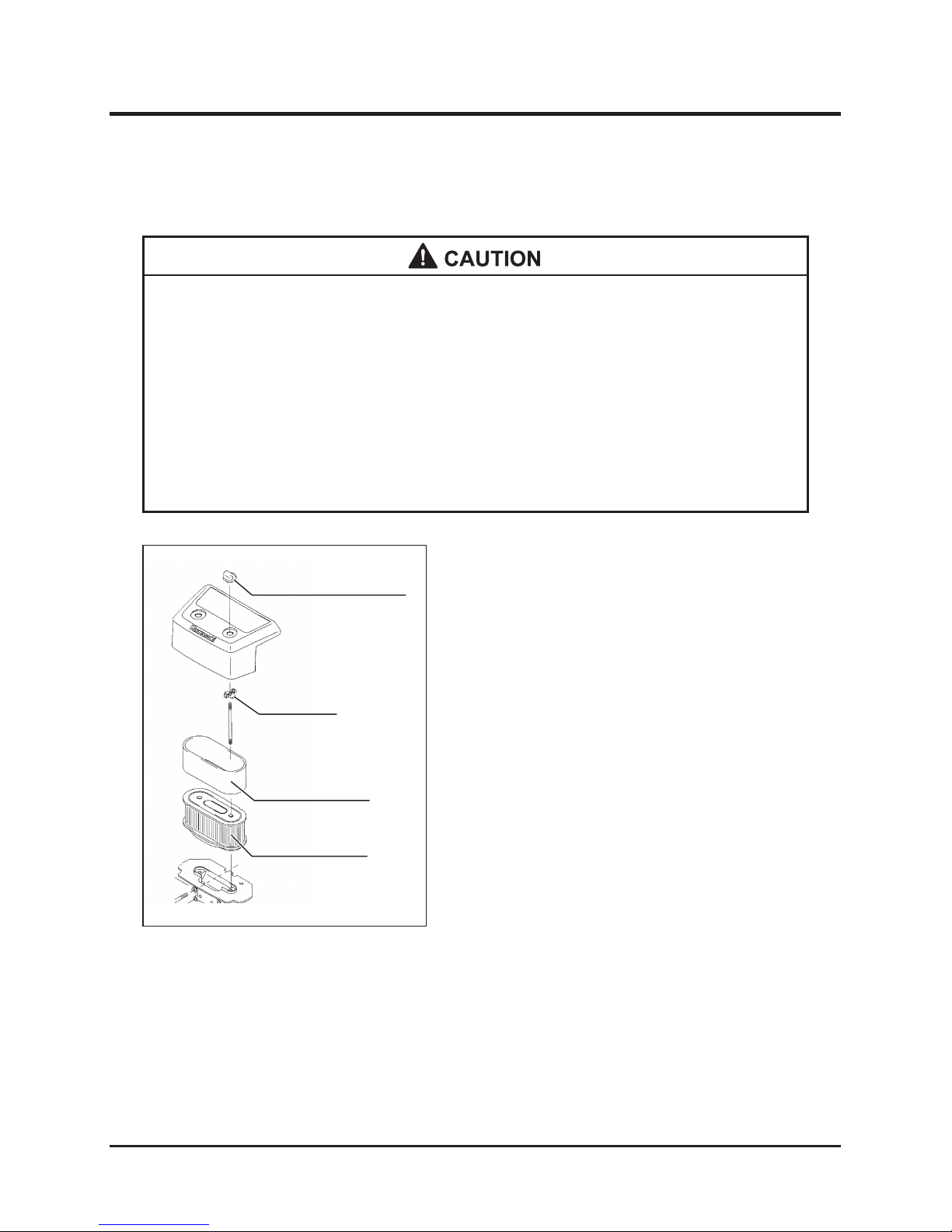
Air cleaner case nut
Wing bolt
Foam element
Paper element
* Check and clean the air cleaner periodically (every 25 hours for the foam
element and every 50 hours for the paper element). Severely dirty elements
may cause poor starting, insufficient output, and reduce engine life. If there are
any defects in the elements, replace them with new ones.
* Do not use oil for cleaning the dry type paper element. Remove dust from the
paper element by beating it lightly against a flat floor. Do not use compressed
air to clean paper element.
* Handle the elements carefully to avoid breaking or deforming them.
1. Remove the air cleaner case nut and detach
the case.
2. Remove the wing bolts and detach the
elements. Wash the foam element in a vessel
filled with detergent and water, and blow
compressed air against it or shake it to dry.
Then, soak the element with clean engine oil,
and squeeze it to remove excess oil, drying it
as much as possible. Remove dust from the
paper element by beating it slightly against a
flat floor. In both cases, replace any severely
dirty or broken elements with new ones.
3. Cover the paper element with the foam
element, then attach them to the bottom plate
with the wing bolts.
4. Attach the air cleaner case to the element
assembly.
Cleaning and Replacing Air Cleaner
5310M-0707-010-E
Page 59
-53-
Maintenance 7
Cleaning Cooling System
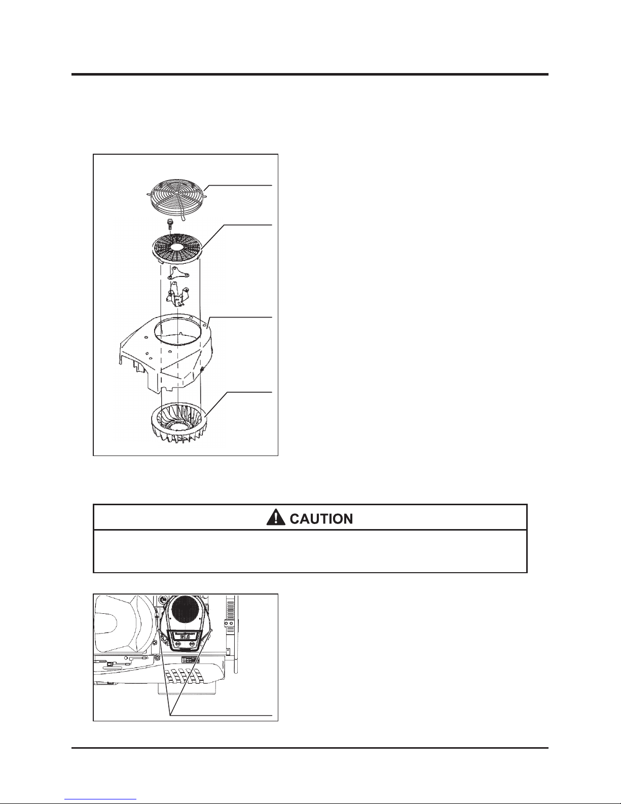
1. Remove the air cleaner cover, fan cover guard,
and fan cover.
2. Clean the fan housing and cooling fan using
compressed air.
5317M-0704-010-E
Cooling fan
Fan housing
Fan cover
Fan cover guard
Inspecting, Cleaning, and Replacing Ignition Plug
Ignition plug cap
1. Remove the ignition plug cap.
Inspecting Ignition Plug
* Avoid pulling the cord when removing the ignition plug cap.
5317M-0704-010-E
5310M-0707-020-E
Page 60
Maintenance
-54-
7
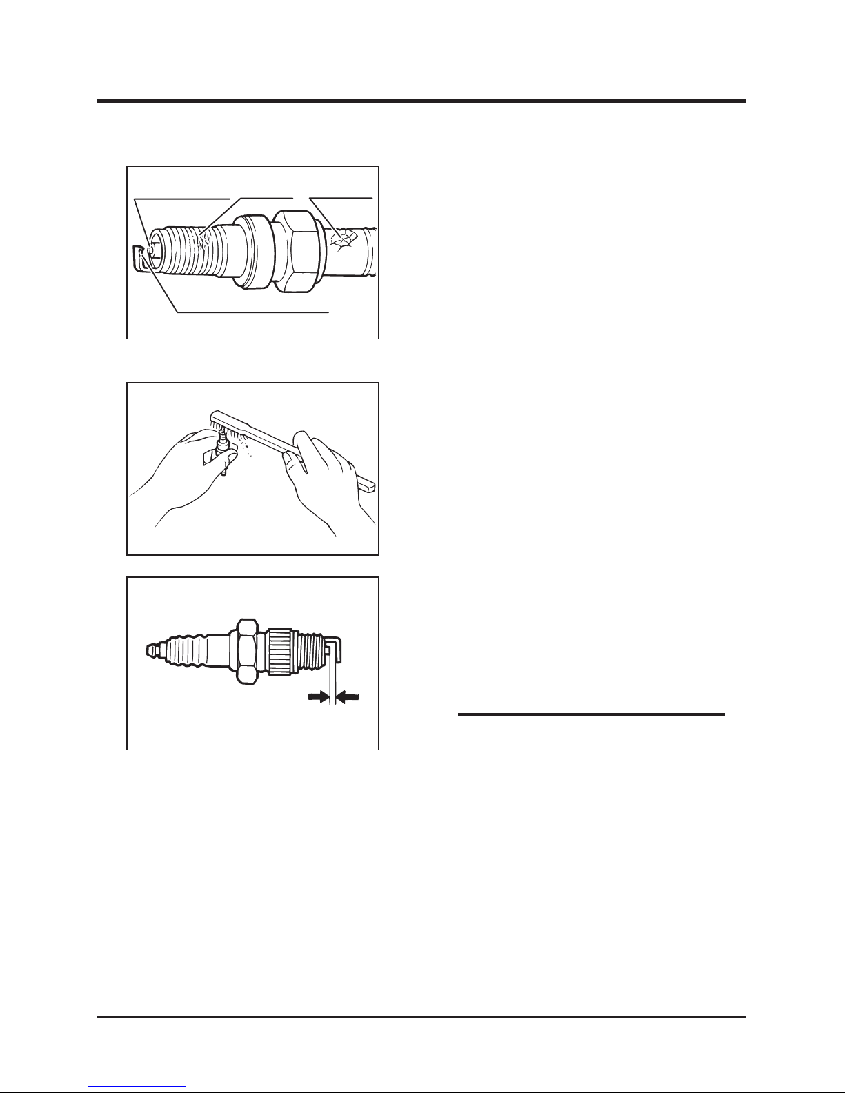
Degree of burning
Damage
Breakage
Wear, carbon deposit
5310M-0707-030E
5310M-0707-040-E
2. Remove the ignition plug with a plug wrench.
3. Check for the following defects, or damage.
Replace plug if damaged or cannot be
cleaned.
* Damage to insulator
* Worn electrodes
* Carbon deposits on electrodes
* Damage or breakage of gasket
* Burned insulator
Cleaning Ignition Plug
1. Clean the ignition plugs with a wire brush and
plug cleaner.
2. Adjust the electrode (spark) clearance with
sandpaper, to keep the following clearance:
3. Install the ignition plug.
4. Attach the ignition plug cap.
Standard clearance: 0.75 mm
5310M-0707-050-E
* Plug model number: See page 15
NOTE
Page 61
-55-
Maintenance 7
Draining Fuel
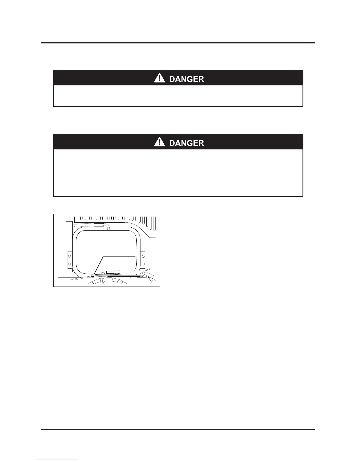
1. Remove the drain plug and drain fuel together
with any water and sediment from fuel system.
2. Securely attach the drain plug.
Fuel System
* Always stop the engine before performing maintenance.
5317M-0705-010
Drain bolt
* Keep flames and flammable away from fuel.
* Avoid spilling fuel. Immediately wipe up spilled fuel.
* Properly dispose of waste fuel after removing from machine.
5317M-0705-010-E
Page 62
Maintenance
-56-
7
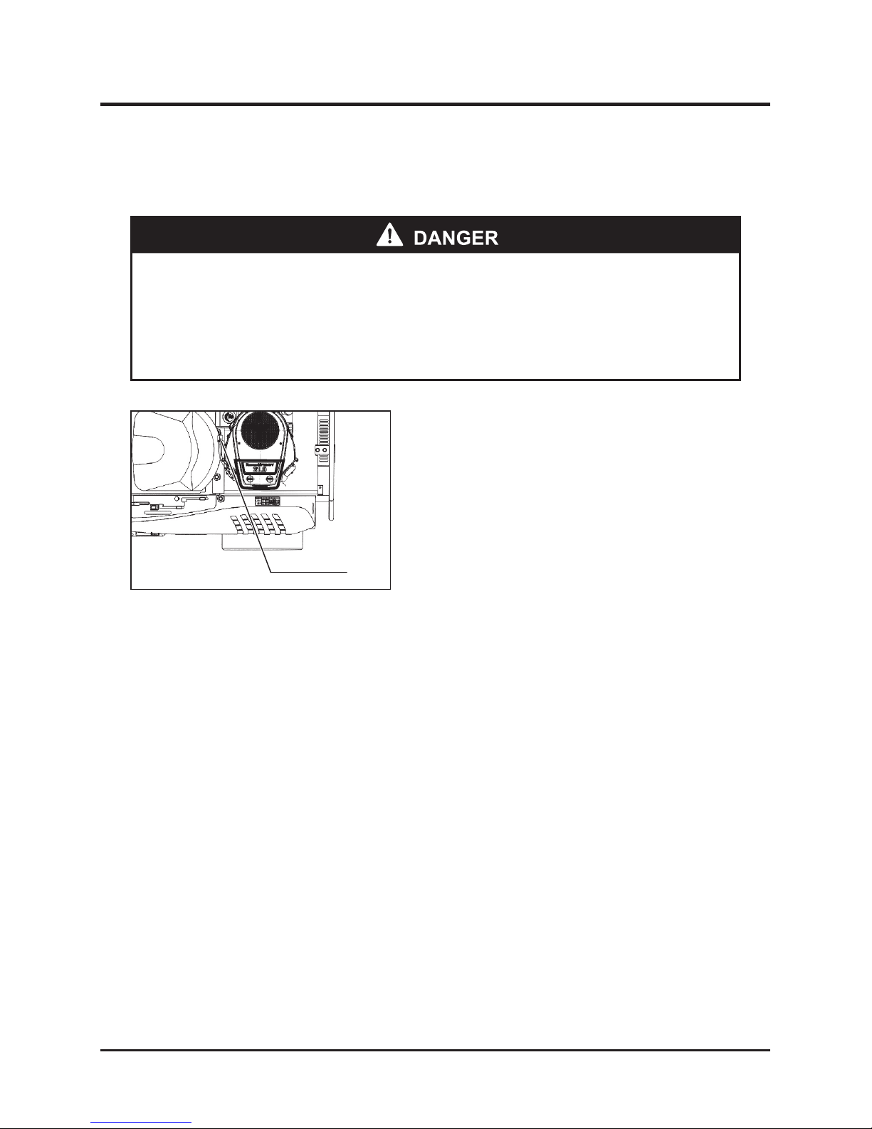
Fuel filter
Inspection
1. Check the fuel filter color. The normal color of
the filter is light brown.
2. When the fuel filter is severely dirt (black
color), ask a CHIKUSUI CYANYCOM dealer to
replace the filter.
Inspecting Fuel Filter
* A black fuel filter is clogged and may prevent fuel from reaching the engine,
causing the engine to stop.
* A CHIKUSUI CANYCOM authorized dealer should replace the fuel filter to
reduce the risk of fire at the fuel filter-fuel hose joint.
5310M-0707-060-E
Page 63
-57-
Maintenance 7
Hydraulic System
* Always stop the engine before performing maintenance.
* Allow oil and system parts to cool before performing maintenance to reduce
risk of burns.
* Properly dispose of waste hydraulic oil after reaming from machine.
Inspecting, Adding, and Replacing HST Oil
* Maintain proper oil level to prevent air from entering system and disrupting
operation.
Inspection
1. Park the machine on level ground.
2. Open the engine cover.
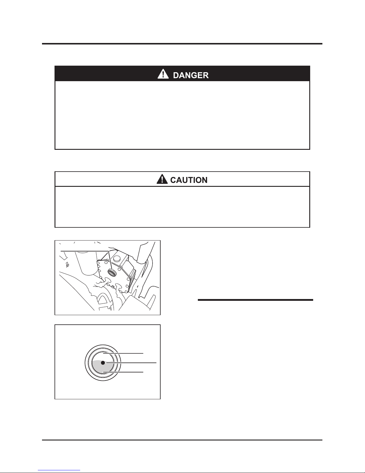
3. Check the oil level gage visually to confirm the
hydraulic oil level.
* Check the hydraulic oil level before starting
the engine. The hydraulic oil level cannot
be precisely measured just after the engine
stops.
NOTE
4. When the oil level is low, add the specified
hydraulic oil.
5. When the hydraulic oil is severely dirty, replace
it with fresh oil.
Oil level guage
Oil level guage
Proper amount
HIGH
LOW
5116M-0507-020-E
5310M-0502-030-E
Page 64
Maintenance
-58-
7
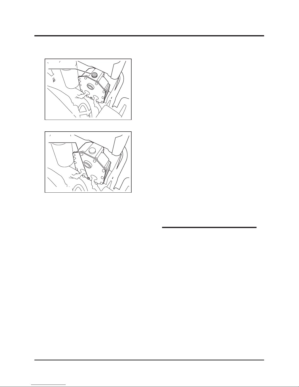
1. Remove the cap from the hydraulic oil filler
port.
2. Add the specified hydraulic oil to the oil filler
port.
3. Check the oil level gage and confirm that the
system is filled with the specified amount of
the hydraulic oil.
4. Securely attach the cap to the oil filler port.
Adding Oil
1. Position a vessel suitable for receiving the
drained oil under drain plug.
2. Remove the drain plug and drain the present
oil from the hydraulic system.
3. Attach the drain plug.
4. Add the fresh specified hydraulic oil. (Check
the amount of the supplied oil.)
5. Start the engine to expel air from the hydraulic
system.
6. Confirm that the system is filled with the
specified amount of the hydraulic oil.
Replacing Oil
* Replace the HST oil filter when replacing the
hydraulic oil. (See page 59.)
* Specified hydraulic oil: See Page 47.
* Amount of hydraulic oil: See Page 47.
NOTE
Filler cap
Drain plug
5317M-0706-020-E
5317M-0706-010-E
Page 65
-59-
Maintenance 7
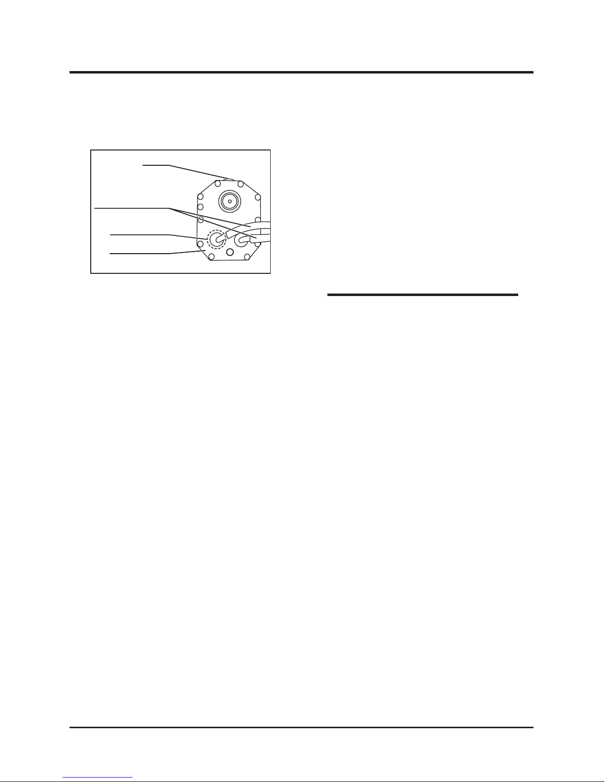
Replacing HST Oil Filter
1. Drain the oil from the oil tank.
2. Remove the oil hose connecting to the oil tank.
3. Remove the tank cover and replace the oil filter
inside the tank with a new one.
4. Attach the oil tank cover and oil tank
connecting hose.
5. Add oil to the oil tank.
Cap
Oil tank connection hose
Oil filter position
Oil tank cover
5314M-0709-020-E
* Confirm that there is no oil leak from the
filter-mounting part, hose connecting ports,
and joints.
NOTE
Page 66
Maintenance
-60-
7
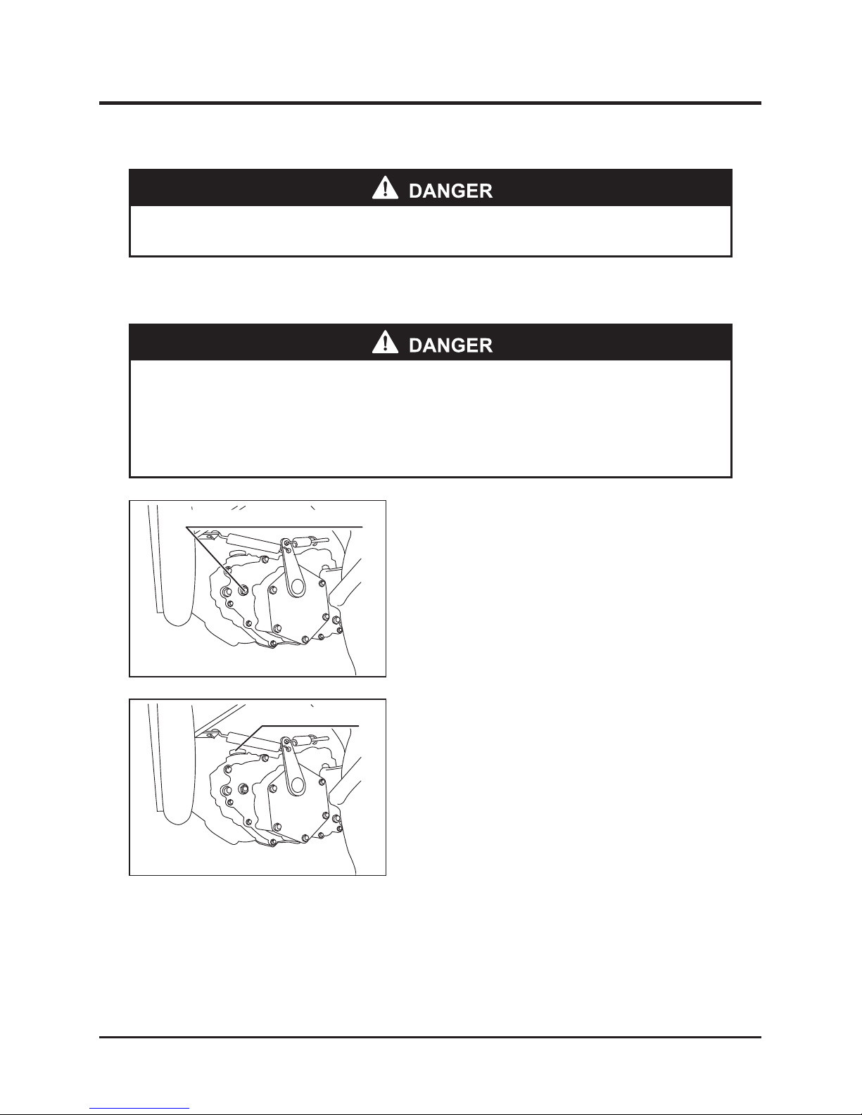
Oil level check bolt
5314M-0704-020E
Lubricating plug
5314M-0704-030E
Inspecting, Adding, and Replacing Transmission Oil
1. Park the machine on level ground.
2. Remove the oil level check bolt from the
oil-checking port. Oil level is sufficient if drains
from the port.
Inspecting Oil
Adding Oil
1. Remove the plug from the oil filler port.
2. Add the specified transmission oil to the oil
filler port.
3. Securely attach the plug to the oil filler port.
Running System
* Always stop the engine before performing maintenance.
* Allow oil and parts to cool before performing maintenance to reduce risk of
burns.
` Properly dispose of waste oil after removing from machine.
Page 67
-61-
Maintenance 7
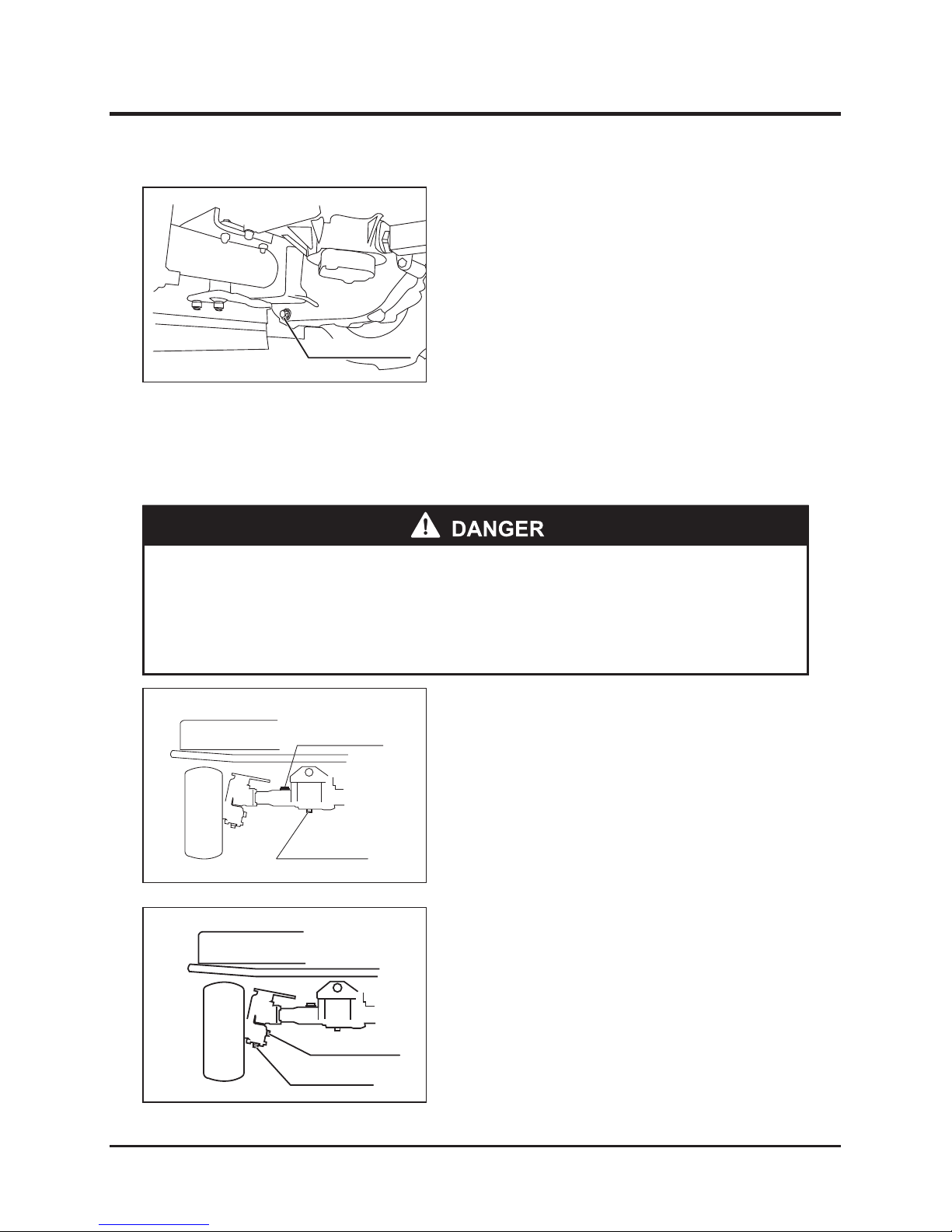
Drain plug
5314M-0704-040E
1. Position a vessel suitable for receiving the
drained oil under the drain plug.
2. Remove the drain plug and drain the present
oil from the draining port.
3. Attach the drain plug to the draining port.
4. Remove the plug from the oil filler port.
5. Add the specified transmission oil to the oil
filler port.
6. Securely attach the plug to the oil filler port.
Replacing Oil
Lubricating plug
Drain plug
5310M-0704-050E
Differential oil
Drain plug
Knuckle oil
Lubricating plug
5310M-0704-060E
Replacing Differential Oil and Knuckle Oil
1. Position a vessel suitable for receiving the
drained oil under drain plug.
2. Remove the drain plug and drain the oil from
the drain port.
3. Attach the plug to the drain port.
4. Remove the lubricating plug.
5. Add the specified oil to the lubricating port.
6. Securely attach the plug to the lubricating port.
Replacing Oil
* Allow oil and parts to cool before performing maintenance to reduce risk of
burns.
* Properly dispose of waste oil after removing from machine.
Page 68
Maintenance
-62-
7
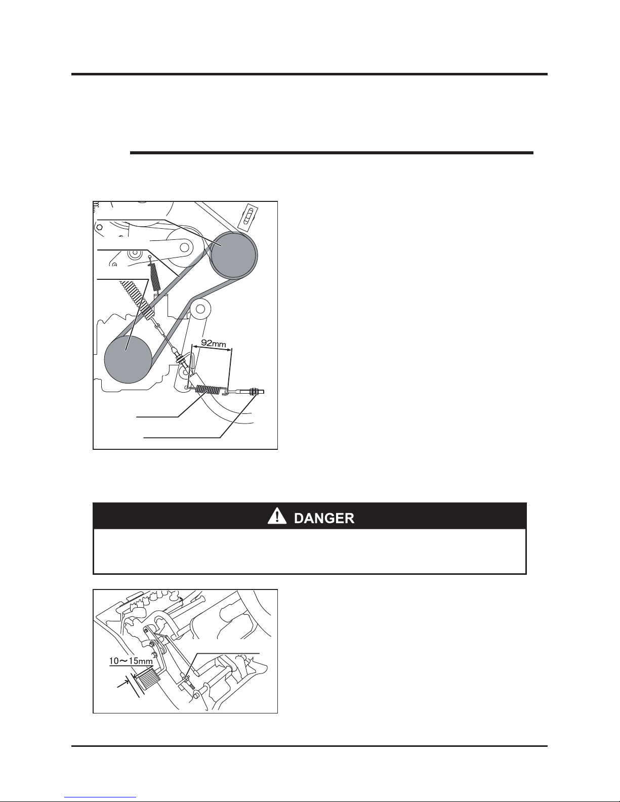
Inspecting and Adjusting Driving V-Belt
Spring
Adjustment nut
HST pulley
Driving
V-belt
Engine pulley
5314M-0708-010E
* Perform maintenance without changing V-belt tension. Adjust V-belt tension only after it
slips.
NOTE
Visually check each V-belt for damage. Replace
any damaged V-belt.
Inspecting V-belt
Adjust the adjusting nut to make the spring length
92 mm.
Adjusting V-belt
Adjusting Brake Pedal
Adjustment nut
5314M-0708-040E
* Immediately adjust brake pedal play when it becomes large to prevent
accidents.
Turn adjusting nut to make play 10 to 15 mm at
the pedal back when depressing the brake pedal
slightly.
Adjusting Brake Pedal
Page 69
-63-
Maintenance 7
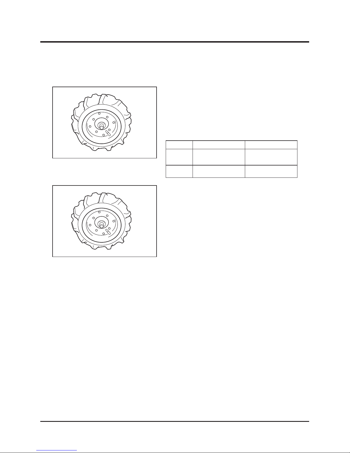
Checking Tire Pressure
5317M-0502-020
Checking Wheel Bolts
Tighten the wheel bolts to the following specified
torque.
5317M-0502-020
Tire size
Air pressure kPa (kgf/cm2)
Front wheel 4.00 - 7 240 (2.4)
Rear wheel
17 x 8.00 - 8 240 (2.4)
* Specified torque: 39.2 to 44.1 N•m (4.0 to
4.5 kgf•m)
Check the pressures of the front and rear wheel
tires. If they do not meet the standard values,
adjust them.
To prevent flat tires, the boundaries between the
tires and hubs outside and inside of the wheels
are filled with a tire protective agent (Ultraseal).
Page 70
Maintenance
-64-
7
Battery
Upper
Lower
Cover
5314M-0706-010E
1. Park the machine on level ground.
2. Check the battery electrolyte level visually. If
the electrolyte is low, add water to the battery.
* Proper battery electrolyte level: between
upper and lower reference lines
* Add only distilled water to battery
Electrical Equipment
Inspecting Battery Electrolyte and Adding Water
* Keep flames and flammable material away from battery.
* Stop using battery when the electrolyte level is below the lower limit to avoid
shortening battery life and reduce risk of explosion.
* Clean battery with wet cloth. Avoid using dry cloth, to prevent static electricity
from causing an explosion.
* Immediately wash away any battery electrolyte (diluted sulfuric acid) contacting
clothing or skin with plentiful water. Immediately wash eyes with water if
electrolyte enters eyes and call a doctor.
* When adding water to the battery, avoid exceeding upper limit level when
adding water to battery to prevent spilling and overflow which may damage
painted surfaces and corrode parts.
* Always stop the engine and turn the main switch to "OFF" before performing
maintenance.
Page 71
-65-
Maintenance 7
Charging Battery
* Remove the battery from machine before charging.
* Keep flames and flammable material away from battery to avoid fire caused by
hydrogen gas.
* Do not charge the battery when the battery electrolyte level is lower than the
"LOWER LEVEL" line to reduce risk of explosion.
* Clean the battery with wet cloth. Avoid using dry cloth to prevent static
electricity from causing an explosion.
* Immediately wash away any battery electrolyte (diluted sulfuric acid) contacting
clothing or skin with plentiful water. Immediately wash eyes with water if
electrolyte enters eyes and call a doctor.
* Follow instructions in the manual of the battery to be used.
* When disconnecting the battery terminals, always disconnect the negative (-)
battery terminal first. When connecting the battery terminals, always connect
the positive (+) terminal first. Avoid placing metallic tools between the machine
and the positive terminal to prevent short circuits.
* Correctly identify terminals when connecting the terminals to the battery.
Connect terminals so battery cables do not contact machine parts.
* Charge battery if necessary with normal charging method after finishing
operations. Use quick charging (with heavy inrush current) only for emergency
charging to avoid shortening battery life.
Page 72
Maintenance
-66-
7
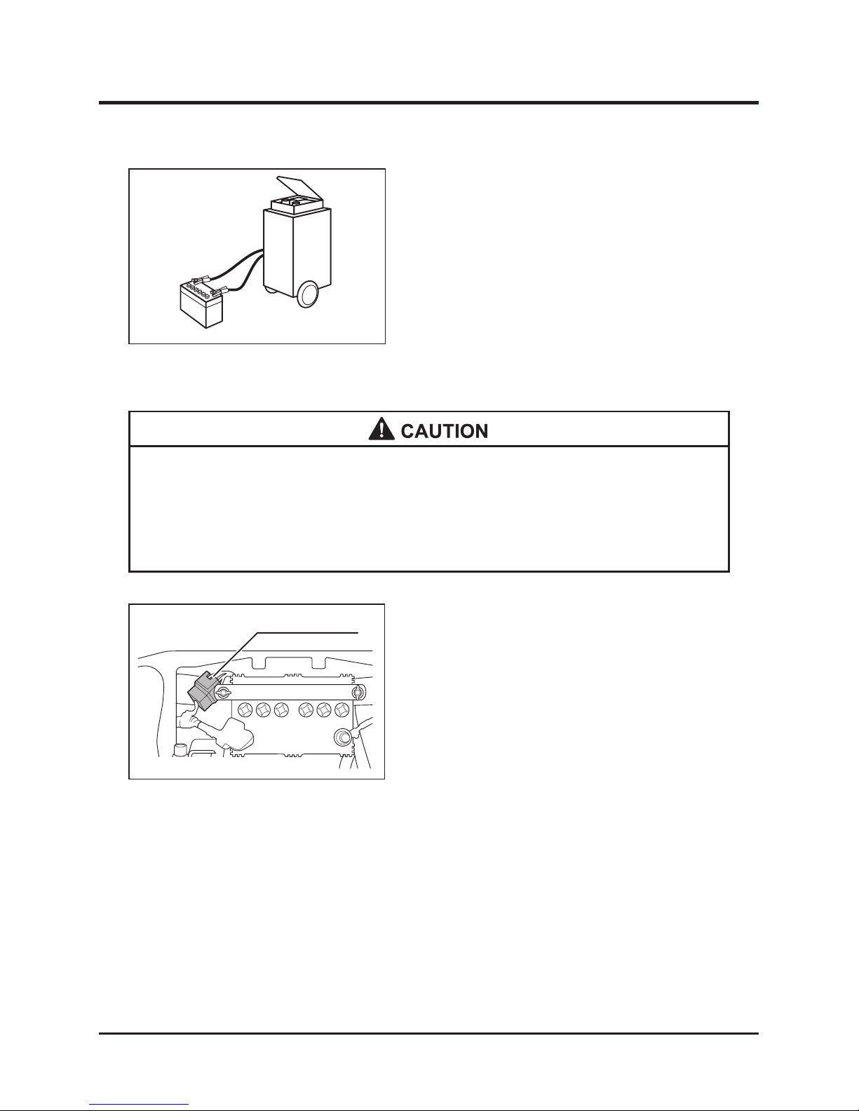
1. Remove the battery from the machine.
2. Charge the battery according to the
instructions in the manual of the battery to be
used.
5116M-0509-040
Inspecting and Replacing Fuses
Fuse box
5317M-0708-010-E
* When a fuse has blown, examine the cause first. Do not replace the fuse before
correcting the cause.
* Replace the blown fuse with a new one with the same specified capacity to
avoid electrical equipment failure.
1. Remove the front cover of the fuse box and
check the fuse inside the fuse box.
2. When the fuse has blown, replace it with a new
one having the same specified capacity.
Page 73
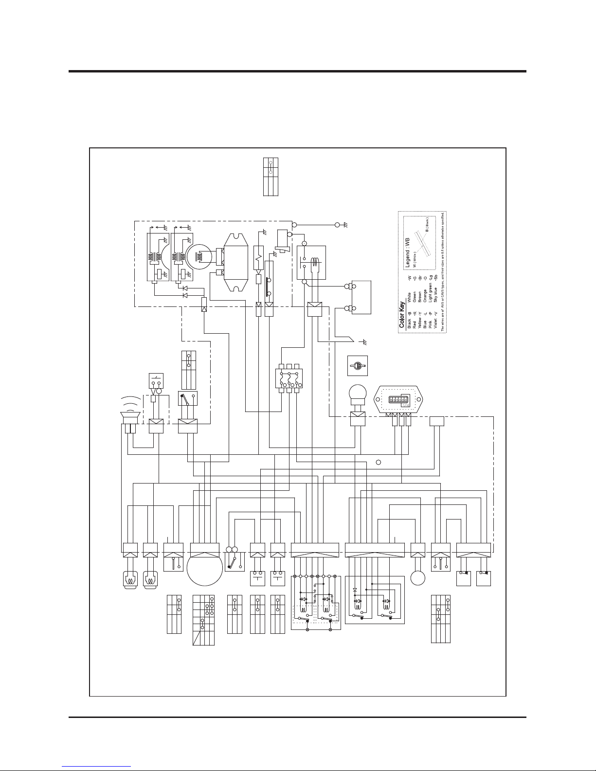
-67-
Maintenance 7
Electric Circuit Diagram
Neutral
5317M-0708-020E
LB
0.85RL
2GW
L
2R
2B
2G
12
20c
17
7
Oa
11
18
P
2G
2B
ORW2Y
2WR
NC
LG
BW
BBLBR
0.85BY
BR
2G
2W
B
BY
2L
3
8Oe6165
LR RW
BGLR
LR
LR
20b
4
BG
0.85BR
4
9
2
0
15
20
3
0.85RW
0.85Br2B0.85R
BL
NC
COM
NO
8
0.85BY
0.85BR
9
BAT
E(GND)
B'IGST
2
1
20a
RW32RL
NC
B
BB
R
B
R
Oc
Od
32
32a
RL
RL
State
1 2
ON
OFF
E B' BAT IG ST
Terminal
Position
OFF
ON
ST
Key switch
Lamp Switch
Head lamp
(L)
(R)
12V-23W×2
Brake switch
Blade clutch
switch
Relay Assembly
Safety switch
(HST)
(Start)
Depressed
Released
State of pedal
ON
OFF
Outter blade clutch
JP2 JP1
JP3
(UP)
(Down)
Relay Assembly
Blade height motor
(UP)
(DOWN)
Blade height
switch
(DOWN)
(UP)
2G
2YGBBLGBPL
O
1314Of
131814
17
11
12
M
2B
2W
213
RBR
B
RW
B
Og
RW
20e
20f
BG
BR
5
4a
B
GRW
20d
62
0.85YL
4 123
HOURS
Hour meter
Hydraulic lamp
2B
6
Ob
BW
EB 15BY
B
3R
0.85YL
62
20
G0.85RW
0.85Br
15
B
10
Seated
Unseated
State
Seat switch
Horn switch
COM
NO
NC
15a
16
Br
LG
R
B
W
GBr
B
60
Oh
イロハ
0.85R
2W
3R
111
b
a
2WR
20A
15A
20A
10
2
7
(Stop)
1 2 3
Blade height moter
Battery
Magnet switch
HEB 15BR
HEB 15BR
1
EB 15BY
After fire stop solenoid
Hydraulic
pressure
switch
Starter motor
State of pedal
Not pressurized
Pressurized
Regulator
(13A)
Charge coil
Ignition plug
Ignition plug
Unit
Unit
W
W
2W
GBr
RW
20g
60
Horn
(12V1.5A以下
)
0
- +
Rotary blade height adjusting switch
HSTlever
Other than neutral
Contraction
Stop
Elongation
Page 74
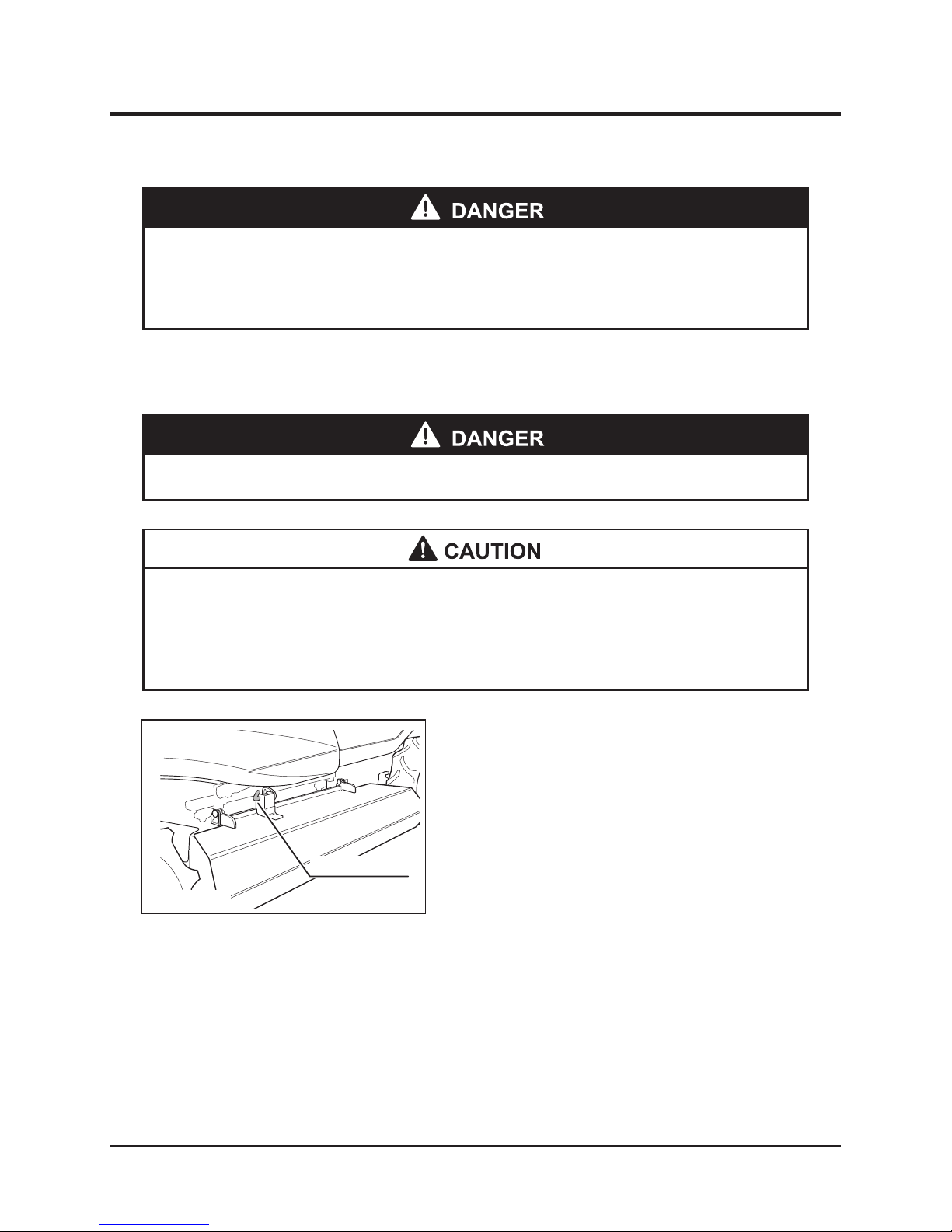
Maintenance
-68-
7
Cutting Unit
* Always stop the engine before performing maintenance.
* Allow parts to cool before performing maintenance to reduce risk of burns.
Opening Grass Chute Cover
Cover lock pin
5317M-0709-010-E
1. Remove both the safety pins.
2. Pull the cover lock pin off and open the grass
chute cover.
3. Securely insert the pin to lock the cover.
4. Replace any worn or damaged safety pin with
a new one.
* Avoid catching hands and fingers in grass chute cover when opening.
* Close grass chute cover after inspecting and return the opening/closing lock
pins to their original positions.
* Open grass chute cover only for inspection.
Page 75
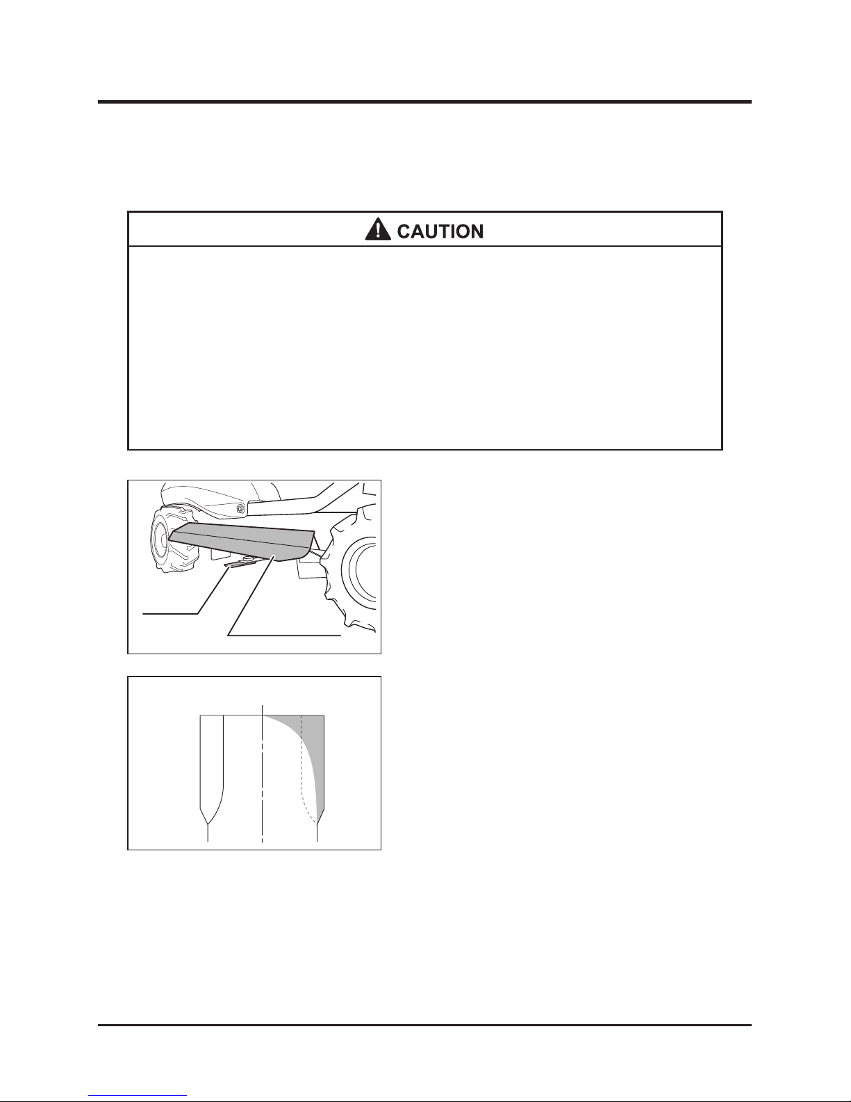
-69-
Maintenance 7
1. Open the grass chute cover.
2. Check for wear, breakage, and missing cutting
blades.
Inspection
5317M-0709-020-E
Cutting blade
Grass chute cover
(open state)
5317M-0709-030-E
3. Replace worn, deformed or broken blades or
bolts. Blade should be replaced when wear
exceeds cross hatched area as shown in
illustration to left. Observe above CAUTION
when replacing blades.
4. Replace missing cutting blades and bolts.
Inspecting and Replacing Cutting Blades
* Immediately replace broken cutting blades to avoid unbalanced rotation in the
rotary cutter causing irregular vibrations and failure.
* Always replace blades in pairs to avoid unbalanced rotation causing irregular
vibrations and failure.
* Always check the cup square neck bolt wear and replace if heavily worn.
* Wear thick gloves when handling the cutter blades and handle them carefully,
wrapping their tips with thick cloth.
Page 76
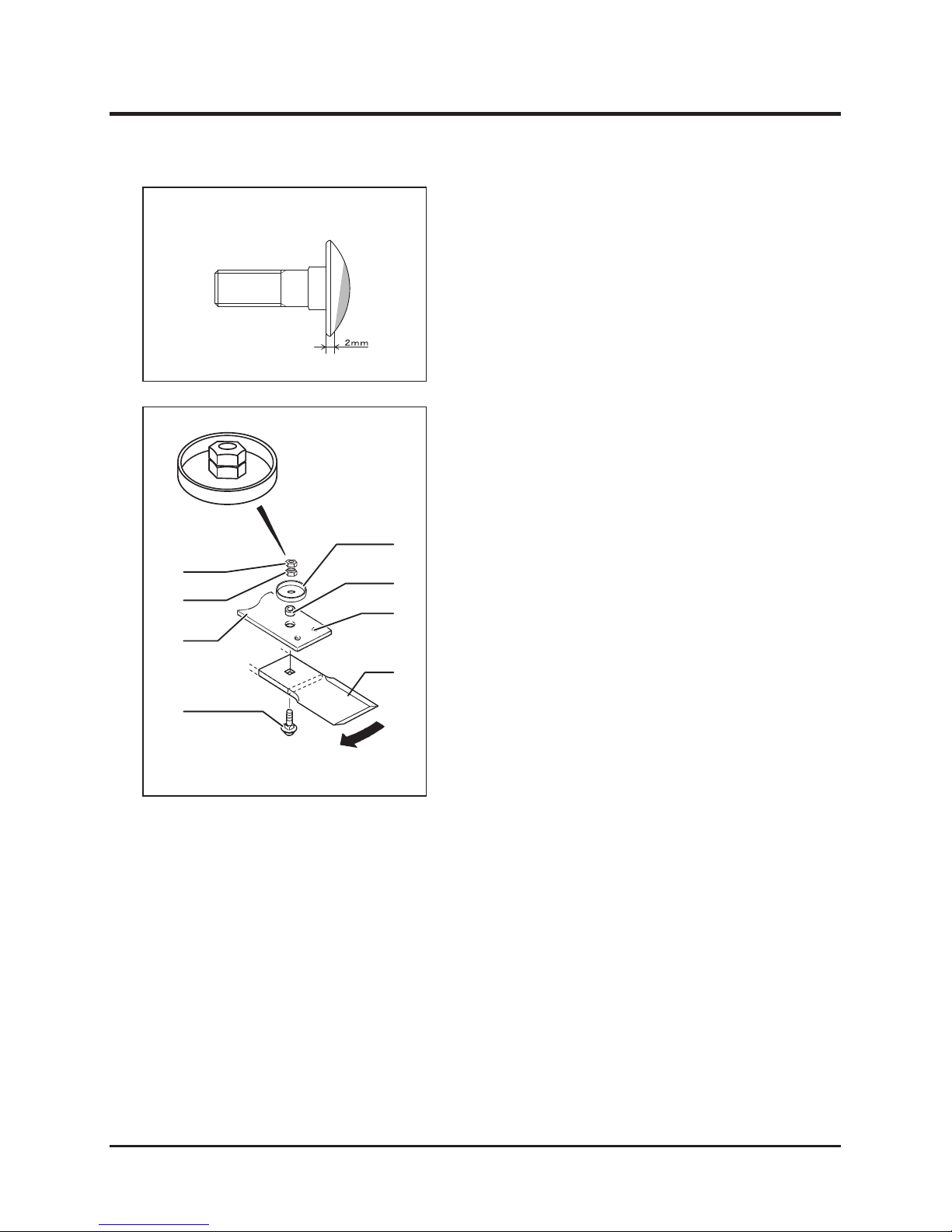
Maintenance
-70-
7
1. Open the grass chute cover.
2. To prevent the rotation of the rotary cutter,
insert a high strength bar, such as a
screwdriver, into the hole “I” of the blade stay.
First, shift the failed blade, turning it around the
cup square neck bolt “J”, then insert the bar (as
shown by broken lines in the left illustration).
3. Remove the nut “K” and nut “L”, in order, with
a closed wrench or socket wrench, and then
remove blade.
4. Place a new blade under the blade stay and
insert the cup square neck bolt from the
bottom side.
5. Place the collar “M” and cap “N” to the cup
square neck bolt.
6. In order to prevent the rotation of the rotary
cutter, insert a high strength bar such as a
screwdriver, into the hole “I” of the blade stay.
First, shift the new blade, turning it around the
cup square neck bolt “J”, then insert the bar (as
shown by broken lines in the left illustration).
7. Tighten the nut “L” to the specified torque.
8. Tighten the nut “K” to the specified torque.
Replacement
* Specified torque: 44.1 to 53.9 N•m (4.5 to
5.5 kgf•m)
5317M-0709-040-E
Cup square neck bolt
Stay
Cup square
neck bolt “J”
Collar “M”
Hole “I”
Cap “N”
Blade
Direction of rotation
5317M-0709-050-E
Nut “K”
Nut “L”
Page 77
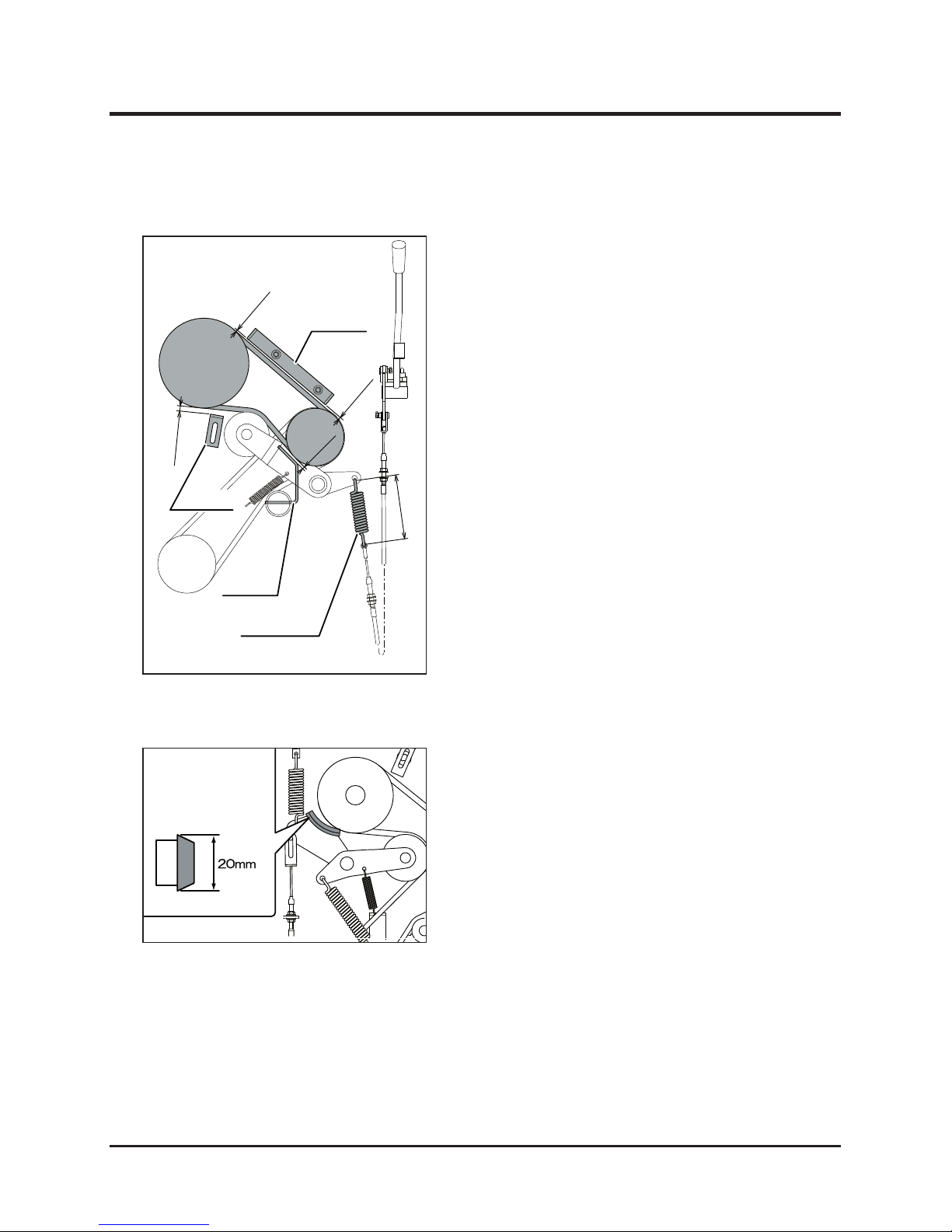
-71-
Maintenance 7
Inspecting and Adjusting Rotary Driving V-Belt
Check each V-belt visually for damage. Replace
the damaged belts with new ones.
Inspecting V-Belt
After the V-belt is replaced adjust the new V-belt,
according to the following procedure.
Adjusting V-Belt
1. When the cutting blade clutch is “ON”, set the
clearance between the guide “A” and V-belt
at 2 to 4 mm, that between the guide “B” and
V-belt at about 10 mm, and that between the
guide “C” and pulley at about 5 mm.
2. Adjust the length of the spring “D” to 122 mm
with the adjusting nut when shifting the cutting
blade clutch lever to "ON".
Inspecting and Adjusting Rotary Cutter Brake
Brake lining
5314M-0708-030-E
Confirm that the rotary cutter stops within about
4 seconds when shifting the cutting blade clutch
lever to "OFF". When it does not stop, check
the wear of the brake lining. If the worn lining is
less than 20 mm in thickness, ask a CHIKUSUI
CANYCOM dealer to replace the brake lining.
Inspecting Rotary Cutter Brake
5317M-0709-060-E
122 mm
2
~4 mm
2
~
4 mm
About 10 mm
About 5 mm
Guide “B”
Guide “C”
Guide “A”
Spring “D”
Page 78
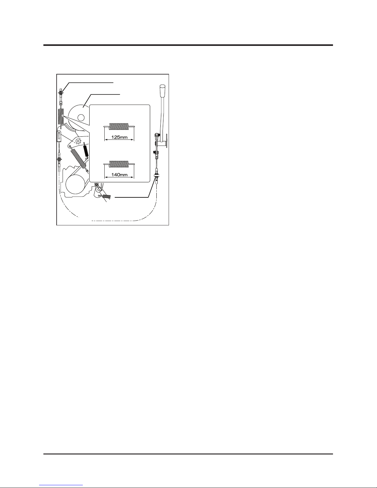
Maintenance
-72-
7
Adjustment nut “G”
Blade pulley
Spring “F”
When shifting the blade clutch lever to
the “OFF” position
When shifting the blade clutch lever to
the “ON” position
Adjustment nut “E”
5314M-0708-050-E
When the rotary cutter does not stop within about
4 seconds after shifting the cutting blade clutch
lever to "OFF", and when the rotary stopper is
replaced, adjust the rotary cutter brake according
to the following procedure.
Adjusting Rotary Cutter Brake
1. Confirm that the engine stops.
2. Adjust the length of the spring “F” to 125 mm
with adjusting nut “G” when shifting the blade
clutch lever to “OFF”.
3. Adjust the length of the spring "F" to 140 mm
with adjusting nut "E" when shifting the blade
clutch lever to "ON".
Page 79
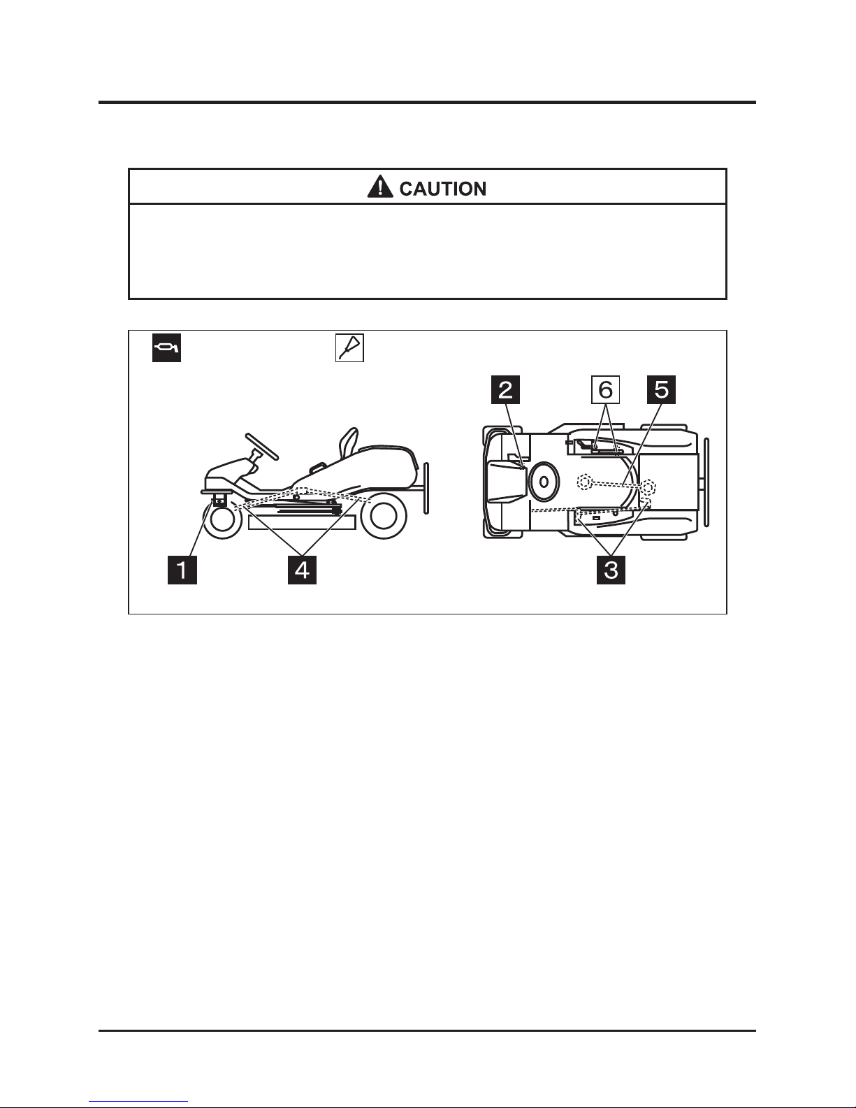
-73-
Maintenance 7
* When using a manual type grease pump, push its handle five to six times.
When resistance becomes heavy, immediately stop pushing. When using a
pneumatic type grease pump, pumping for two to three seconds is enough.
Grease point
Oil point
5317M-0502-010-E
Lubrication and Greasing
Disposal of Waste
Dispose waste, according to states and local regulations.
Page 80

Storage
-74-
8
Maintenance After Use in Normal Conditions
1. Eliminate any foreign matter such as grass and soil, especially from the engine and
rotating parts, after using the machine.
2. Cover machine with a waterrepellent sheet after the engine has completely cooled down
when leaving the machine outdoors.
* Do not use a high pressure washer to avoid causing machine failures.
* Do not wash the engine and control panels with water to avoid causing failures
and rust due to soaking.
* Do not splash water on the electrical equipment.
* Completely remove surface moisture to prevent failures caused by freezing.
* Do not try to move machine if freezing makes operation impossible.
1. Remove all dirt, water and foreign objects from the body to prevent material from freezing
and causing malfunctions.
2. Place the vehicle on a concrete floor, dry firm ground or wooden blocks.
3. Cover the vehicle with a water-proof sheet when placing it outdoors.
Maintenance After Use
Maintenance After Use in Cold Season
Storage
Page 81
-75-
Storage 8
Long-Term Storage
1. Park machine according to “Stopping” described on Page 35.
2. Completely check machine and repair or replace defective parts according to “Periodical
Check Sheet” shown on Page 44.
3. Remove all foreign matter such as grass and soil from the machine.
4. Wipe clean the outside of the machine with oil-soaked cloth then grease or lubricate the
portions where greasing or lubrication is required. (See Pages 20 and 73.)
5. Increase tire pressure to slightly higher than the standard value and block the wheels.
6. Replace the engine oil. (See Page 49.)
7. Clean the air cleaner elements. (See Page 52.)
8. Drain the fuel remaining in the tank. (See Page 55.)
9. Remove the battery from the machine, check the battery electrolyte, and add water if low.
(See Page 64.)
10. Cover machine with a water repellent sheet for storage after the engine has completely
cooled down.
* Do not wash the engine and control panels with water to prevent failure and rust
due to soaking.
* Completely remove surface moisture to prevent failures caused by freezing.
* Store machine in a dry, clean environment.
* Avoid storing machine near open flames or flammable material to reduce risk of
fire.
* A battery will usually naturally discharge when not used. A battery can be kept in storage
for about six months without needing charging. To maintain battery life stored batteries
should be charged every six months.
* Refer to the instruction manual attached to the engine for details about long-term storage
of the engine.
NOTE
Page 82
Troubleshooting
-76-
9
Troubleshooting
Area Malfunction Possible cause Corrective action
Engine
Engine does not start * Blade clutch lever is not
in "OFF". (Safety device is
actuated.)
→ Put the lever to "OFF".
* Brake pedal is not depressed.
(Safety device is working.)
→ Depress brake pedal.
* Battery is over-discharged. → Charge battery.
(See page 65)
→ Replace battery.
(See page 66)
* Battery cable is disconnected. → Connect cable.
* Fuse is blown. → Replace.
* Open circuit or contact failure
of wiring
→ Repair. (Consult dealer.)
Difficulty starting * Lack of fuel → Add. (See page 18)
* Air or water in fuel → Check pipe and tightening
band. Repair or replace.
* Excessive intake of fuel → Start after interval.
* Engine oil too low or poor
quality (High oil viscosity)
→ Add or replace.
(See page 49)
* Poor ignition due to dirt on
spark plug or poor sparking
→
Clean or replace. (See page 53)
* Insufficient capacity of battery
(Poor electric starting)
→ Replenish battery fluid.
→ Charge battery.
(See page 65)
* Impurities in fuel circuit → Replace the fuel filter.
(Consult dealer.)
Engine stalls soon
* Lack of fuel → Add. (See page 18)
Engine stops abruptly
* No fuel → Add. (See page 18)
* Burn due to insufficient or dete-
riorated engine oil
→ Check and add oil.
(See page 49)
Improper idling
(lrregular engine speed)
-
→ Ask dealer for service.
Poor power or acceleration
* V-belt loosened → Adjust.
* Improper accelerator adjustment → Ask dealer for service.
* Clogging of air cleaner → Clean or replace.
(See pages 52)
* Stop using machine immediately after any malfunction or abnormal operation occurs. Use
troubleshooting chart (below) to identify problems and corrective actions. Please contact
dealer or CHIKUSUI CANYCOM service center for problems not listed in chart.
* Contact dealer or CHIKUSUI CANYCOM service center for service requiring special tools
or knowledge.
Troubleshooting
Page 83
-77-
Troubleshooting 9
Area Malfunction Possible cause Corrective action
Engine
Abnormal noises or vibrations
from in or around the engine
* Looseness of engine mounting
bolts
→ Check and carry out additional
tightening.
* Others → Consult dealer
Excessive engine oil * Engine oil leak → Check and repair.
Engine overheating * Insufficient engine oil → Add. (See page 49)
* Blower housing and cooling fin
clogging
→ Clean. (See page 53)
Excessive fuel consumption * Fuel leak from fuel system → Check and repair.
(Consult dealer.)
* Clogged air cleaner → Clean or replace.
(See pages 52)
Excessive black smoke
(Abnormal exhaust)
* Choke not opened completely → Put choke to FULL position.
* Poor compression → Check and repair.
(Consult dealer.)
* Clogged air cleaner → Clean or replace.
(See pages 52)
* Excessive oil intake → After checking adjust oil
volume. (See page 49)
* Poor fuel → Replace fuel.
White smoke or blue smoke
comes out. (Abnormal
exhaust)
* An excessive amount of engine
oil added.
→ After checking adjust oil
volume. (See page 49)
* Improper fuel → Replace fuel.
* Worn cylinder or piston ring → Check and repair.
(Consult dealer.)
Power
transmission
system
Unit does not move with HST
lever in forward or reverse.
* Insufficient HST oil → Add. (See page 57)
* Parking brake is applied. → Release parking brake lock
lever.
Unit moves even when HST
lever is in neutral position.
* HST speed shift neutral position
adjustment not correct.
→ Adjust. (Consult dealer.)
Brake system
Not effective * Worn out brake lining → Replace lining.
(Consult dealer.)
* Oil penetrates within brake
drum.
→ Replace oil seal.
(Consult dealer.)
* Water penetrates inside of
drum.
→ Engine brake to dry water
inside of drum.
* Worn out tire → Replace tire.
Excessive play of brake pedal. * Incorrect adjustment → Adjust. (See page 62)
Steering
system
Heavy steering * Incorrect tire air pressure → Adjust. (See page 63)
* Malfunction inside of steering
gear
→ Repair.
(Consult dealer.)
Cannot drive straight * Incorrect tie-rod adjustment → Adjust.
Chassis
Abnormal vibration of the
chassis
* Incorrect tire air pressure
adjustment
→ Adjust tire air pressure.
(See page 63)
* Loose tire fixing bolt → Retighten.
* Breakage of wheel bearing → Replace.
(Consult dealer.)
* Crack of tire → Replace.
Page 84
Troubleshooting
-78-
9
Area Malfunction Possible cause Corrective action
Lighting
system
Head lamp failure * Improper wiring → Connect properly.
* Bulb is disconnected. → Replace.
* Blown fuse → Replace.
Grass cutter
devices
Mown grass not discharged
well
* Wet grass → Perform the operation after
grass becomes dry.
* Grass too long →
Mow twice with a higher mowing
height
* Mowing height too low → Set the mower to a higher
mowing height.
* Low engine speed → Set the mower to the
maximum motor speed.
* High work speed → Work more slowly.
Some grass is left unmown. * High work speed → Work more slowly.
* Low engine speed →
Set the mower to the maximum
motor speed. (Check engine
speed.)
* Grass too long → Mow twice.
* Wear and breakage of cutter → Replace the blade with a new
one. (See page 69)
* Accumulation of grass on the
internal surface of the rotary
cover
→ Clean the internal surface of
the rotary cover.
The mower cuts into the soil. * Mowing height too low → Set the mower to a higher
mowing height. (See page 23)
* High swing speed → Reduce swing speed.
* Ground contours → Change the mowing pattern.
(mowing direction, etc.)
* Too many bumps and dips in
the ground
→ Set the mower to a higher
mowing height.
* Bent mowing blade → Replace the blade with a new
one. (See page 69)
Rotary cutter blade does not
rotate.
* Broken driving pin for cutter
blade driving propeller shaft
→ Replace the driving pin.
* Slip in the rotary cutter V-belt → Adjust the tension of the V-belt.
Extreme shaking * Grass accumulated in the rotary
cover and pulley
→ Clean the rotary cover and
pulley.
* Damaged belt → Replace the belt with a new
one.
* Damaged pulley → Replace the pulley with a new
one.
* Damaged blade → Replace the blade with a new
one. (See page 69)
Cutter overloaded * Poor blade balance → Replace the blade with a new
one or balance the blade
properly. (See page 69)
* Low engine speed → Increase engine speed
to maximum value.
(Check engine speed.)
* Operating speed too high → Slow down operating speed.
* Grass accumulating or coiling
around blade
→ Clean blade.
Page 85

-79-
10Gurantee and After-Sales Service
The company guarantees this product (or the machine), according to the contents of the
warranty. For details, refer to the warranty attached to the back of this manual.
Guarantee and After-Sales Service
For malfunctions, questions, and after-sales services regarding to this product, contact
the dealer from whom you purchased this product. Tell the dealer the model and product
numbers indicated on the model label (See Page 1), and the name of the manufacturer of the
engine and engine model number (See Page 12).
Guarantee
After-Sales Service
Availability of Replacement Parts
CHIKUSUI CANYCOM will make replacement parts for this machine available for seven
years after the end of this machine model’s production.
Page 86
Accountable receipt of guarantee certificate
Based on the instruction manual for the following product I have purchased, I have been given guidance and explanations as to
the safe operation as well as handling and control and I have received this guarantee certificate.
Dealer (Duplicate)
Customer
(signature)
Address
Name
Product
purchased
Model name
Production
number
Dealer
Delivery
inspection
(Person in charge)
Explainer
Date of explanation
Person who recived
explanations
Dealer name
Remarks
Page 87
Accountable receipt of guarantee certificate
Based on the instruction manual for the following product I have purchased, I have been given guidance and explanations as to
the safe operation as well as handling and control and I have received this guarantee certificate.
Customer (Duplicate)
Customer
(signature)
Address
Name
Product
purchased
Model name
Production
number
Dealer
Delivery
inspection
(Person in charge)
Explainer
Date of explanation
Person who recived
explanations
Dealer name
Remarks
Page 88
Guarantee certificate
Thank you very much for purchasing CHIKUSUI CANYCOM products.
We offer you this guarantee:
1. Period of guarantee: Shall be one year from the date of delivery.
2. Extent of guarantee: If a defect in design and/or manufacturing
is found in the product parts or materials during the period of
guarantee and our company acknowledges this defect, we
will replace or repair the part in question, free of charge,at
our company's authorized dealer, agricultural cooperative
association, or its designated service factory.
3. This guarantee does not cover:
(1) Cases where failure results from carelessness in use and
handling, negligence, or improper inspection or maintenance.
(2) Cases where failure results from the use beyond the limits,
specified by our company in product documentation.
(3) Cases where modifications or alterations not approved by
our company causes failure.
(4) Cases where failure results from non-approved parts.
Our warranty does not cover Product failures resulting
from the use of non-CANYCOM replacement parts, or from
installation and use of add-on, modied, or unapproved
accessories.
(5) Cases where failure results from repairs not done by
company’s authorized dealer, agricultural cooperative
association, or its designated service factory.
(6) Cases where failure determination materials are insufficient
and the damaged part is lost.
(7) Consumable (replacement) parts
(8) Cases when guarantee and purchase receipt are not
available to verify product history.
(9) Product failures resulting from operating the Product beyond
the limits specified in our operators instruction manual.
(10) Product failures due to unapproved oil/lubricants, additives,
chemicals or other materials used in product.
(11) Product failures due to Force Majeure such as earthquakes,
unusual weather, accidents, res, or other natural disasters.
(12) Cost for transporting claimed parts or any claims for other
loss or damages from failure of the Product to operate
during any period of time, including indirect or consequential
damage.
(13) Sensitive phenomena such as sound and vibration which do
not affect product function or performance.
(14) Normal “wear and tear” includes, but is not limited to,
damage due to wearor abrasion, worn painted surfaces,
scratched decals or windows and other minor effects.
4. Lost guarantee certicate will not be reissued.
CHIKUSUI CANYCOM, INC.
90-1 Fukumasu, Yoshii-machi,
Ukiha gun, Fukuoka, Japan 839-1396
TEL. 81-(0)943-75-2195
FAX. 81-(0)943-75-4396
 Loading...