

Page 1

Ride-on Brushcutter
CMX 227/ CM226/ CMX186/ CM185
Operator's Manual
5321 5311 003
Read this manual completely before operating or maintaining this machine.
Failure to follow safety precautions could result in serious injury or death.
Keep this manual for future reference by you and by all those who operate
and maintain this machine.
Original Instructions
(in English)
5335 5311 003
Page 2

http://www.canycom.co.jp/
90-1 Fukumasu, Yoshii-machi,
Ukiha-shi, Fukuoka, Japan 839-1396
Sales Headquarters (International) TEL +81-(0)943-75-2195
FAX +81-(0)943-75-4396
Authorized Dealer
All rights reserved. Unauthorized use or reproduction of this material is prohibited.
Page 3
Notice to Users and Maintenance Personnel
Thank you for purchasing this machine.
This manual provides information needed for safe and effective use of this machine to those
who operate or maintain machine. Make sure to read and understand the manual thoroughly
before operating this product. Also make sure to read the separate operator's manual for
engine.
• This machine can be very dangerous if the safety precautions in this manual
and on the labels attached to this machine are not followed. Read and
understand this manual and safety labels on machine thoroughly before using
this machine. Always follow the instructions and safety precautions, or serious
injury or death could result.
• This machine should only be used for its intended purpose: cutting grass and
bushes. Any other use could be dangerous.
• This machine may not be operated on public road or what is considered to
be public road. It is the sole responsibility of the operator to consult the local
regulations.
• Do not modify this machine, or do not operate this machine with the safety
covers removed or open. A serious accident could result.
• Store this manual in a safe, accessible place for easy reference.
Page 4
Notice to Owner
• Be sure that everyone who uses this machine, including those who rent or
lease this machine, receives a copy of this Operator's Manual and understands
the importance of reading and following the information in this manual.
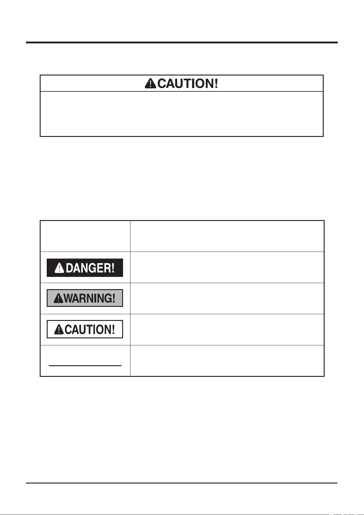
Warning Terms Used in this Manual
In this manual, the following four warning terms are used to signal the four levels of hazard (or
seriousness of possible accidents). Read and understand what they mean and always follow
the instructions in this manual.
Warning Term Denition
Indicates an imminently hazardous situation which will result
NOTE
in death or serious injury if the user does not follow the
procedures or the instructions.
Indicates a potentially hazardous situation which could result
in death or serious injury if the user does not follow the
procedures or the instructions.
Indicates a potentially hazardous situation which could result
in minor to moderate injury or damage to the machine if the
user does not follow the procedures or the instructions.
Indicates important information which needs particular
attention.
Page 5
Warranty and After-Sales Service
Warranty
CHIKUSUI CANYCOM, INC. guarantees this product, based on the terms of warranty.
After-Sales Service
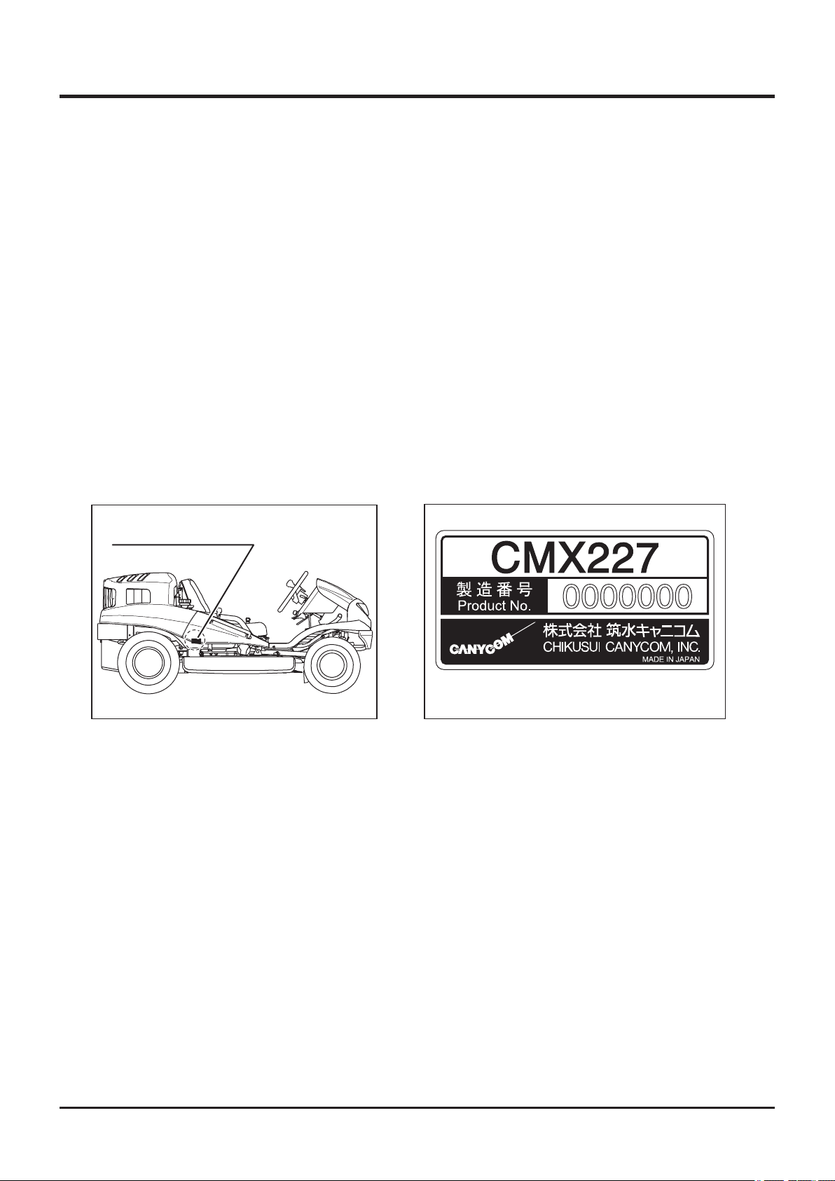
Consult your local CANYCOM dealer or our company’s sales department regarding service
orders or any questions or problems that may arise when using this machine. Please make
sure to have the product name, serial number, and the make and type of engine handy at
the time of contact. The model and serial number can be found on the model label as shown
below, and the make and type of the engine can be found in Chapter 3 "Specications" of
this manual (Page15).
Location of Model Label
Location of Model Label
5332M-0005-010E
Model Label
5335M‑0005‑020
Availability of Spare Parts
The replacement or repair parts for this product shall remain available for seven years after
the production of this type of machine is discontinued.
Page 6

Contents
1. Safety 1
Safety Labels . . . . . . . . . . . . . . . . . . . . . . . . . . . . . . . . . . . 1
Safety Mechanisms . . . . . . . . . . . . . . . . . . . . . . . . . . . . . . 3
Safety Precautions . . . . . . . . . . . . . . . . . . . . . . . . . . . . . . . 4
Training . . . . . . . . . . . . . . . . . . . . . . . . . . . . . . . . . . . . . . . . . . . . . . . . . . . . . . . 4
Preparation . . . . . . . . . . . . . . . . . . . . . . . . . . . . . . . . . . . . . . . . . . . . . . . . . . . . 5
Operation . . . . . . . . . . . . . . . . . . . . . . . . . . . . . . . . . . . . . . . . . . . . . . . . . . . . . . 6
Servicing . . . . . . . . . . . . . . . . . . . . . . . . . . . . . . . . . . . . . . . . . . . . . . . . . . . . . 10
2. Controls and Components 11
Name and Function of Controls . . . . . . . . . . . . . . . . . . . 11
3. Specications 15
Product Specications . . . . . . . . . . . . . . . . . . . . . . . . . . 15
Contents of Tool Bag . . . . . . . . . . . . . . . . . . . . . . . . . . . 16
4. Operation 17
Preparation . . . . . . . . . . . . . . . . . . . . . . . . . . . . . . . . . . . . 17
Pre-start up Inspection . . . . . . . . . . . . . . . . . . . . . . . . . . . . . . . . . . . . . . . . . . 17
Checking and Filling Fuel . . . . . . . . . . . . . . . . . . . . . . . . . . . . . . . . . . . . . . . 17
Adjusting Steering Wheel . . . . . . . . . . . . . . . . . . . . . . . . . . . . . . . . . . . . . . . 18
Adjusting Seating Position . . . . . . . . . . . . . . . . . . . . . . . . . . . . . . . . . . . . . . 20
Adjusting Drive Pedal . . . . . . . . . . . . . . . . . . . . . . . . . . . . . . . . . . . . . . . . . . . 22
Page 7

Driving . . . . . . . . . . . . . . . . . . . . . . . . . . . . . . . . . . . . . . . . 22
Starting . . . . . . . . . . . . . . . . . . . . . . . . . . . . . . . . . . . . . . . . . . . . . . . . . . . . . . 22
Driving . . . . . . . . . . . . . . . . . . . . . . . . . . . . . . . . . . . . . . . . . . . . . . . . . . . . . . . 26
Stopping . . . . . . . . . . . . . . . . . . . . . . . . . . . . . . . . . . . . . . . . . . . . . . . . . . . . . 28
Shifting . . . . . . . . . . . . . . . . . . . . . . . . . . . . . . . . . . . . . . . . . . . . . . . . . . . . . . . 30
Shifting Between 2WD and AWD (CMX227 / CMX186) . . . . . . . . . . . . . . . . . 30
Locking Differential . . . . . . . . . . . . . . . . . . . . . . . . . . . . . . . . . . . . . . . . . . . . 31
Parking . . . . . . . . . . . . . . . . . . . . . . . . . . . . . . . . . . . . . . . . . . . . . . . . . . . . . . . 32
Working . . . . . . . . . . . . . . . . . . . . . . . . . . . . . . . . . . . . . . . 34
Inspecting Cutting Blade . . . . . . . . . . . . . . . . . . . . . . . . . . . . . . . . . . . . . . . . 34
Adjusting Cutting Height . . . . . . . . . . . . . . . . . . . . . . . . . . . . . . . . . . . . . . . . 34
Cutting . . . . . . . . . . . . . . . . . . . . . . . . . . . . . . . . . . . . . . . . . . . . . . . . . . . . . . . 35
Adjusting Cutting Blade Shield . . . . . . . . . . . . . . . . . . . . . . . . . . . . . . . . . . . 40
5. Maintenance 41
Maintenance Schedule . . . . . . . . . . . . . . . . . . . . . . . . . . 41
Engine . . . . . . . . . . . . . . . . . . . . . . . . . . . . . . . . . . . . . . . . . . . . . . . . . . . . . . . 41
Chassis . . . . . . . . . . . . . . . . . . . . . . . . . . . . . . . . . . . . . . . . . . . . . . . . . . . . . . 42
List of Fluids and Lubricants . . . . . . . . . . . . . . . . . . . . . 45
Greasing Points . . . . . . . . . . . . . . . . . . . . . . . . . . . . . . . . 46
Greasing Points (CMX227 / CMX186) . . . . . . . . . . . . . . . . . . . . . . . . . . . . . . 46
Greasing Points (CM226 / CM185) . . . . . . . . . . . . . . . . . . . . . . . . . . . . . . . . . 47
List of Consumables and Spares . . . . . . . . . . . . . . . . . . 48
Removing and Installing Body Panels . . . . . . . . . . . . . . 50
Front Cover . . . . . . . . . . . . . . . . . . . . . . . . . . . . . . . . . . . . . . . . . . . . . . . . . . . 50
Head Lamp . . . . . . . . . . . . . . . . . . . . . . . . . . . . . . . . . . . . . . . . . . . . . . . . . . . . 51
Engine Hood . . . . . . . . . . . . . . . . . . . . . . . . . . . . . . . . . . . . . . . . . . . . . . . . . . 52
Lower Rear Cover . . . . . . . . . . . . . . . . . . . . . . . . . . . . . . . . . . . . . . . . . . . . . . 52
Step . . . . . . . . . . . . . . . . . . . . . . . . . . . . . . . . . . . . . . . . . . . . . . . . . . . . . . . . . 52
Seat Bracket . . . . . . . . . . . . . . . . . . . . . . . . . . . . . . . . . . . . . . . . . . . . . . . . . . 53
Cutting Blade Shield . . . . . . . . . . . . . . . . . . . . . . . . . . . . . . . . . . . . . . . . . . . . 53
Page 8

Engine . . . . . . . . . . . . . . . . . . . . . . . . . . . . . . . . . . . . . . . . 55
Engine Oil . . . . . . . . . . . . . . . . . . . . . . . . . . . . . . . . . . . . . . . . . . . . . . . . . . . . 55
Oil Filter Cartridge . . . . . . . . . . . . . . . . . . . . . . . . . . . . . . . . . . . . . . . . . . . . . 57
Air Cleaner . . . . . . . . . . . . . . . . . . . . . . . . . . . . . . . . . . . . . . . . . . . . . . . . . . . . 57
Spark Plugs . . . . . . . . . . . . . . . . . . . . . . . . . . . . . . . . . . . . . . . . . . . . . . . . . . . 58
Drive Train . . . . . . . . . . . . . . . . . . . . . . . . . . . . . . . . . . . . . 59
Tires . . . . . . . . . . . . . . . . . . . . . . . . . . . . . . . . . . . . . . . . . . . . . . . . . . . . . . . . . 59
Transmission Oil . . . . . . . . . . . . . . . . . . . . . . . . . . . . . . . . . . . . . . . . . . . . . . . 60
Front Axle Oil (CMX227 / CMX186) . . . . . . . . . . . . . . . . . . . . . . . . . . . . . . . . 60
HST (Hydrostatic Transmission) Fluid . . . . . . . . . . . . . . . . . . . . . . . . . . . . . 61
Drive Belt . . . . . . . . . . . . . . . . . . . . . . . . . . . . . . . . . . . . . . . . . . . . . . . . . . . . . 63
Parking Brake . . . . . . . . . . . . . . . . . . . . . . . . . . . . . . . . . . . . . . . . . . . . . . . . . 64
Cutting System . . . . . . . . . . . . . . . . . . . . . . . . . . . . . . . . . 65
Cutting Blades . . . . . . . . . . . . . . . . . . . . . . . . . . . . . . . . . . . . . . . . . . . . . . . . . 65
Cutting Rotary Drive Belt and Cutting Rotary Brake . . . . . . . . . . . . . . . . . . 68
Electrical System . . . . . . . . . . . . . . . . . . . . . . . . . . . . . . . 71
Battery . . . . . . . . . . . . . . . . . . . . . . . . . . . . . . . . . . . . . . . . . . . . . . . . . . . . . . . 71
Fuses . . . . . . . . . . . . . . . . . . . . . . . . . . . . . . . . . . . . . . . . . . . . . . . . . . . . . . . . 73
Light Bulbs . . . . . . . . . . . . . . . . . . . . . . . . . . . . . . . . . . . . . . . . . . . . . . . . . . . 73
After Use Care . . . . . . . . . . . . . . . . . . . . . . . . . . . . . . . . . 75
Cutting System . . . . . . . . . . . . . . . . . . . . . . . . . . . . . . . . . . . . . . . . . . . . . . . . 75
After Normal Use. . . . . . . . . . . . . . . . . . . . . . . . . . . . . . . . . . . . . . . . . . . . . . . 76
After Cold Weather Use . . . . . . . . . . . . . . . . . . . . . . . . . . . . . . . . . . . . . . . . . 77
Storage . . . . . . . . . . . . . . . . . . . . . . . . . . . . . . . . . . . . . . . 78
6. Troubleshooting 79
Troubleshooting . . . . . . . . . . . . . . . . . . . . . . . . . . . . . . . . 79
Page 9

7. Transporting 84
Hauling . . . . . . . . . . . . . . . . . . . . . . . . . . . . . . . . . . . . . . . 84
Loading and Unloading . . . . . . . . . . . . . . . . . . . . . . . . . . . . . . . . . . . . . . . . . 84
Hoisting . . . . . . . . . . . . . . . . . . . . . . . . . . . . . . . . . . . . . . . 85
Warranty
Warranty Certicate is attached at the end of this manual.
* Have the warranty certicate signed after you have received and fully understood
the instructions for handling this machine and received the receipt.
Appendix
• Operator's Manual for the Engine
* Be sure to read and understand it together with this manual .
Page 10
Safety 1
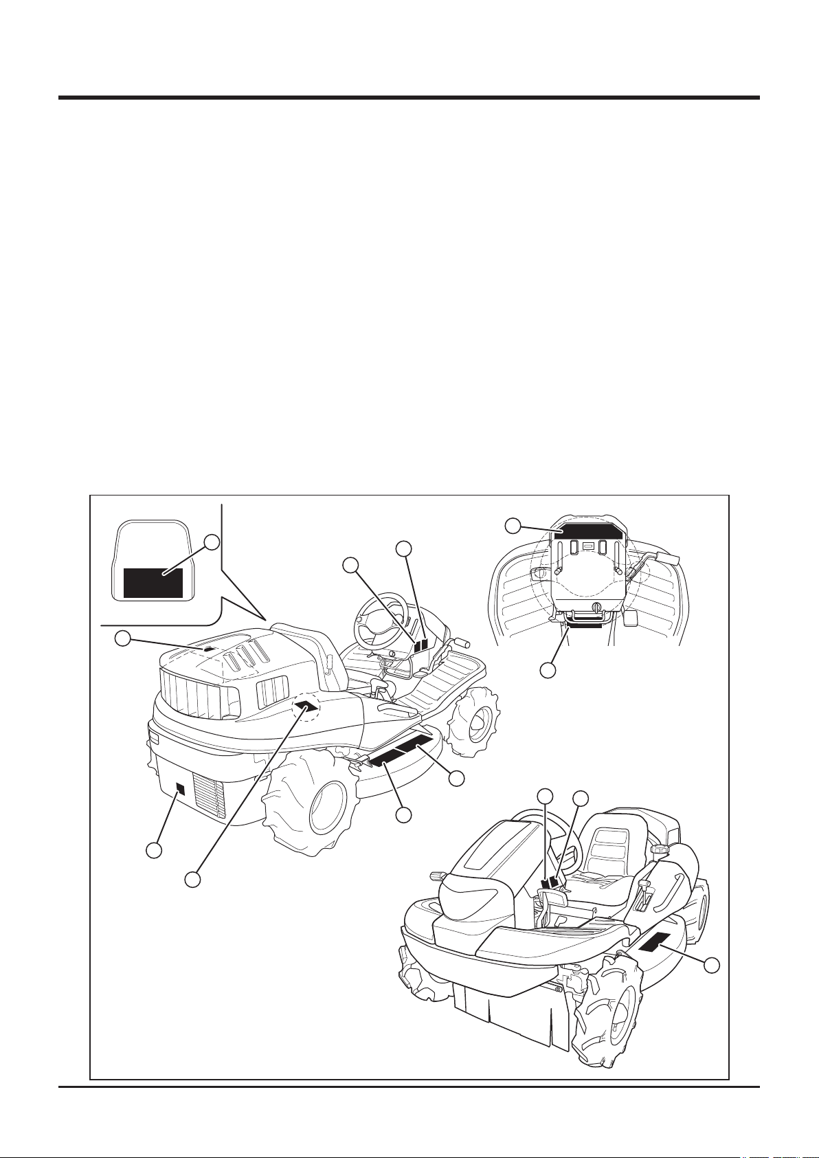
Safety Labels
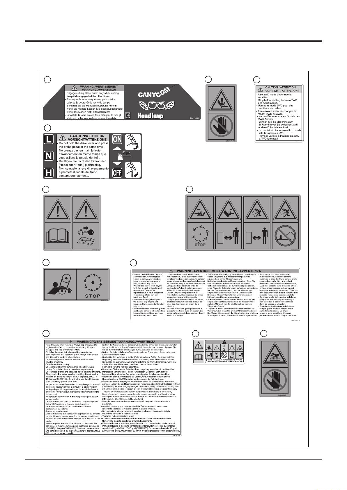
The safety labels shown on the next page are attached to the machine. See the illustration
below for the location and the illustration on the next page for the content of each label on
the machine.
• Locate all the warning labels attached to this machine. Read and follow the instructions
and precautions in them. Failure to do so could result in serious injury or death to the
operator or bystanders.
• Keep the labels clean and legible. Do not use solvents or gasoline to clean the labels.
• Replace these labels immediately if they have been removed, have fallen off or become
illegible. Use the part number, on the label or shown in this manual, to order a replacement
label from your CANYCOM representative.
10
1
9
3
7
11
(Models with the
Charge-pump only)
CMX227 and
4
CMX186
8
2
6
5
3
5335M-0101-012E
6
-1-
Page 11
1
1
5332 5109 000
2
5332 5114 000
5
5332 5128 000
Safety
3
5321 5116 000
6
5332 5121 000
4
5332 5122 000
5305 5326 0007
5335 5125 000
9
5332 5127 0008
5332 5127 000
10
11
3667 5063 000
5332M-0101-020
-2-
Page 12

Safety 1
Safety Mechanisms
This product is equipped with the following safety mechanisms.
Start Interlock Mechanism
Engine can be started only when parking brake is in [ (engaged)] position and cutting
rotary clutch in [OFF] position. This is to prevent unintended movement of machine or cutting
blade when starting engine.
Automatic Blade Stopping Mechanism
Engine stops if operator is not seated while cutting blade is rotating. This is to reduce the
possibility of accident related to moving blade when machine is turned over.
-3-
Page 13

1
Safety
Safety Precautions
This section contains safety precautions to follow when operating and maintaining the
machine. Read and understand the precautions in this section as well as throughout this
manual and follow them when operating or maintaining the machine. Failure to follow safety
precautions could result in property damage, serious injury or death to the operator or
bystanders.
Training
All operators and mechanics should receive practical instructions from their employer or
renter. Such instructions should cover the following issues:
• It is essential to familiarize yourself with the controls, safety labels and the proper use of
the machine.
• Never allow people unfamiliar with these instructions to operate or service the machine.
Do not let anyone under 18 years of age to operate this machine. Local regulations may
restrict the minimum age for operating the machine. Consult your local authority.
• The operator is responsible for the accidents or hazards caused to other people or their
property.
• This machine has a riding capacity for one person only. Do not carry passengers other
than the operator.
• Observe the weight limit of this machine: 120kg.
• Always keep in mind that care and concentration is required when working with ride-on
machines.
• Loss of control on a slope cannot be regained by the application of the brake. The main
reasons for loss of control are:
→ insufcient grip of tires.
→ excessive speed.
→ misjudging of the ground conditions, especially slopes.
-4-
Page 14

Safety 1
Preparation
• Fuel is highly ammable. See Checking and Filling Fuel, page 17, for important safety
information on handling fuel.
• Always wear protective footwear, long trousers, hardhat, safety glasses and ear protection
when operating or servicing the machine. Proper clothing will minimize the chance of
injury. Do not operate the equipment if you have long hair, loose clothing, or jewelry; all of
which may get tangled in moving parts. Do not operate the machine barefoot or with open
sandals.
• Prepare beforehand the working rules and procedures such as signaling and trac control
for the work place. Following such rules will reduce the risk of accidents.
• Never handle fuel or grease, service the engine, or recharge the battery in the presence of
re or spark.
• Perform the daily pre-startup inspection (see Preparation, pages 17) before starting the
machine. Repair or replace damaged parts before starting the machine.
-5-
Page 15

1
Safety
Operation
This machine is intended for cutting grass and bushes. Any other use may pose hazard or
cause damage to the machine.
The stability of the machine is affected by the speed, rate of steering, terrain and the
operator's weight. Always pay close attention to these factors or a loss of control or tip over
could occur, resulting in property damage, serious injury or death.
General Driving
• Do not operate the engine in a conned space where dangerous carbon monoxide fumes
can accumulate.
• Do not touch the engine, mufer or exhaust pipe while the engine is running or soon after
it has stopped. These areas will be very hot and can cause burns.
• Do not operate the machine under the inuence of alcohol or drugs. Do not operate the
machine when you are tired, ill, or not feeling well.
• Always check for obstacles before operating on new terrain. This includes overhead
obstacles such as the branches of a tree.
• Before starting the engine and moving the machine, scan around your surroundings and
make sure all persons and other vehicles are a safe distance away from the machine.
• On a slippery surface, travel slowly and exercise caution to reduce the chance of skidding
or sliding out of control. Never operate on ice.
• Always make certain that there is no obstacle or a person behind the machine when
backing up. After conrming that it is safe to back up, move slowly and avoid sharp turns.
• To reduce the risk of tip over, pay special attention when encountering an obstacle or a
slope, or when braking on a slope or during a turn. See Driving on a Slope on page 8.
• Never attempt to drive over a large obstacle such as rock or fallen tree.
-6-
Page 16

Safety 1
• Always travel slowly and use extra caution when operating on unfamiliar terrain. Be alert
when traveling on changing terrain.
• Never operate on terrain that you are not comfortable with. Avoid terrain that is so rough,
slippery or loose that you feel like you could tip over.
• Do not operate the machine near the edge of a cliff, an overhang or a slide area. Pay
special attention after heavy rain or earthquake.
• Do not make sudden maneuvers. A sudden start, stop, or turn can make the machine lose
control and could cause a tip over. Be especially cautious when traveling on soft or wet
ground.
• Drive at a safe speed, taking into account the surface gradient, surface conditions and
load.
-7-
Page 17

1
Safety
Driving on a Slope
• Never use on a slope steeper than 25 degrees for the CMX227 and the CMX186, and
15 degrees for the CM226 and CM185.
• Driving on a slope can be dangerous. It can result in a tip over and cause serious
injury or death. Take the following precautions.
• Always follow proper procedures for driving on a slope as described in this manual.
• Driving on a slope in a wrong manner can cause a loss of control or a vehicle tip over.
Check the terrain carefully before attempting to drive on a slope.
• Never drive on a slope that you are not comfortable with. Avoid a slope that is so rough,
slippery, or loose that you feel like you could tip over.
• When driving up a slope, proceed at a steady rate of speed and throttle position.
• Never move the throttle lever, the drive lever, the drive pedal or the steering wheel
suddenly.
• If the engine stalls or loses traction during a climb and cannot make it to the top of the
slope, do not try to turn the machine around. Carefully back down slowly, straight down the
slope.
• Drive straight up or down slopes. Avoid turning on a slope.
• When going over the top of a slope, go slow; an obstacle, a sharp drop, or another vehicle
or person could be on the other side of the crest.
• Avoid driving the machine across a slope.
• Before driving down a slope, stop and shift auxiliary transmission to [L (low)] position. Drive
slowly. Use the engine speed to help keep the machine speed low.
-8-
Page 18

Safety 1
Cutting
When conducting cutting operation, take the following precautions.
• Always follow the proper procedures for cutting as described in this manual.
• Shutt off the work site. Post signs to inform of the cutting operation. Close off the site with
rope if necessary to keep people, especially children, off the work site.
• Pay attention to the surrounding area. Rotating cutting blade throws stones, rocks and
debris. This may cause property damage, injury, or death.
• Drive forward when cutting. This best prevents the cutting blades from throwing stones,
rocks, or debris.
• Pay attention to obstacles. This includes overhead obstacles such as the branches of a
tree.
Parking
• Park the machine on a at, level and stable surface. Never park on a slope steeper than
10 degrees. Avoid parking on a slope less than 10 degrees. If parking on a slope less than
10 degrees is absolutely unavoidable, apply the parking brake and block the wheels at the
lower end of the machine.
→ Park the machine facing uphill
→ Do not park sideways on a slope.
• Never park on an instable surface. Do not park near the edge of a cliff.
• Observe all the previous precautions for driving, driving on a slope, loading .
• Whenever you park the machine, apply the parking brake and stop the engine. Remove
the key whenever you leave the machine unattended to prevent unauthorized use or
accidental starting.
• Gasoline is extremely flammable and can be explosive. When parking the machine
indoors, make certain that the building is well ventilated and that the machine is not close
to any source of ame or spark, including appliances with pilot lights.
-9-
Page 19

1
Safety
Servicing
• Do not service the machine when the engine is running. If it is absolutely necessary to run
the engine while servicing, pay attention to the moving parts.
• Do not operate the engine in a conned space where dangerous carbon monoxide fumes
can accumulate.
• Make sure all hydraulic line connectors are tight and all hydraulic hoses and lines are in
good condition and leak-free.
• Keep your body and hands away from pinhole leaks or nozzles that eject hydraulic
uid under high pressure. Use paper or cardboard, not your hands, to search for leaks.
Hydraulic uid escaping under pressure can have sufcient force to penetrate the skin and
cause serious injury.
• Check all fuel lines on a regular basis for tightness and wear. Tighten or repair them as
needed.
• If the engine must be running to perform a service, keep hands, feet, clothing and any
part of the body away from any moving part, especially the cooling fan and the belts at the
back of the engine.
• Do not touch the engine, mufer, or exhaust pipe while the engine is running or soon after
it has stopped. These areas will be very hot and can cause burns.
• The engine must be shut off before checking or adding oil.
-10-
Page 20
Controls and Components 2
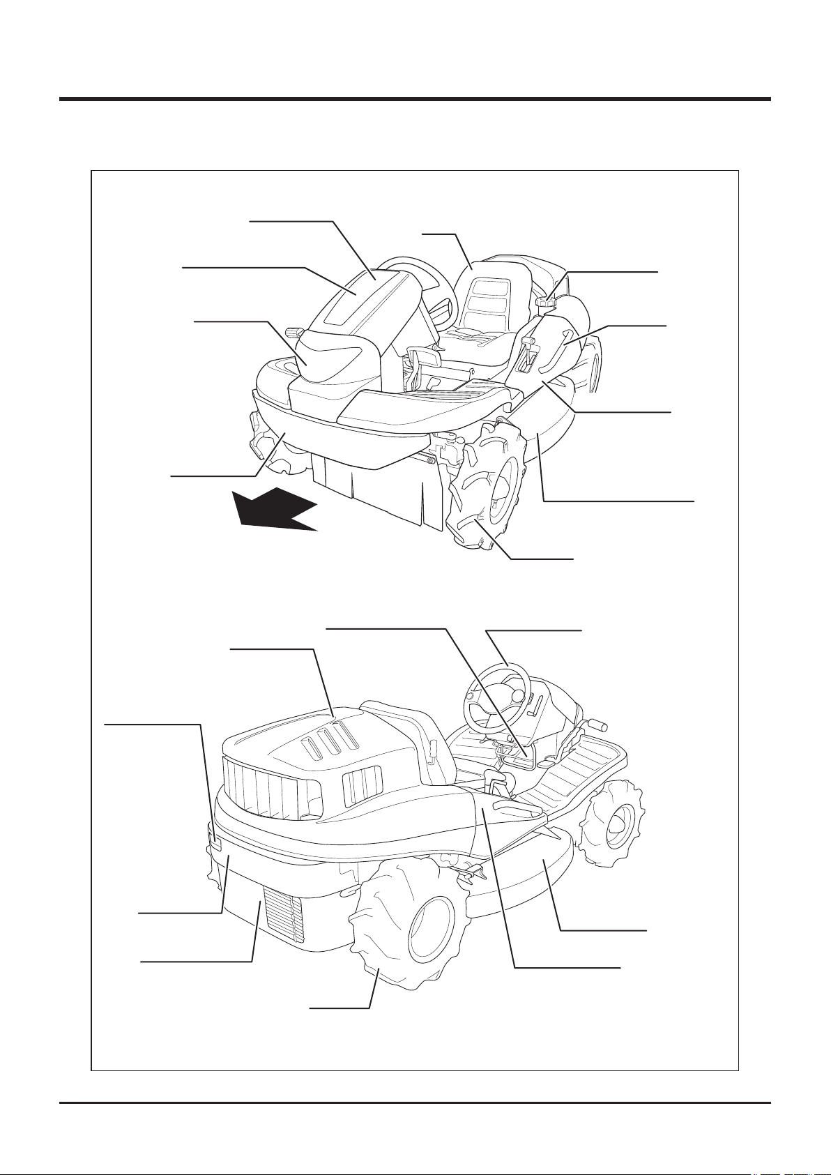
Name and Function of Controls
Front Cover
Tool Box
(Under Front Cover)
Head Lamp
Front Bumper
Forward
Seat
Fuel Filler Cap
Handrail
Side Cover, Left
Cutting Blade Shield, Left
Front Tire
Rear Lamp
(CMX227 Only)
Rear Bumper
Lower Rear Cover
Engine Hood
Plastic Bottle Holder
Rear Tire
Steering Wheel
Cutting Blade
Shield, Right
Side Cover, Right
5335M-0201-010E
-11-
Page 21
2
Controls and Components
17
15
9
7
6
5
2
13
12
1
14
8
3
5335M-0201-020E
4
16
10
11
-12-
Page 22

Controls and Components 2
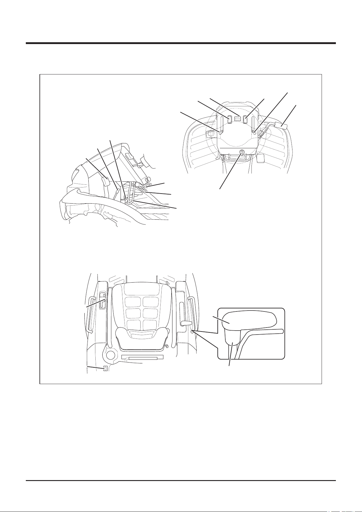
1 Main Switch . . . . . . . . . . . . . Main switch is used to start or stop engine.
2 Throttle Lever . . . . . . . . . . . Throttle lever is used to control engine speed.
3 Drive Pedal . . . . . . . . . . . . . . Drive pedal is used to control the traveling direction and
speed of the machine. Machine moves forward when the
front of drive pedal is depressed and backward when
the rear of drive pedal is depressed. Angle of drive pedal
determines the speed.
4 Drive Lever . . . . . . . . . . . . . . Drive lever is used to control the traveling direction and
speed of machine. Machine moves forward when lever is
tilted forward and backward when lever is tilted backward.
Angle of drive lever determines the speed. (On the right
lever model, this lever is on the right -hand side. See
illustration.)
5 Brake Pedal. . . . . . . . . . . . . . Brake pedal is used to stop machine. When brake pedal
is depressed, drive lever returns to neutral position and
brake is engaged. (On the right lever model, this lever is
on the right -hand side. See illustration.)
6 Parking Brake Lock . . . . . . . Parking brake lock lever is used when parking machine
Lever
7 Auxiliary Transmission . . . . Auxiliary transmission shift lever is used to shift auxiliary
Shift Lever
8 2WD/AWD Shift Lever . . . . . 2WD/AWD shift lever is used to switch between 2WD
securely. Pulling parking lock lever while brake pedal is
depressed locks brake pedal. (On the right lever model,
this lever is on the right -hand side. See illustration.)
transmission to change the speed of the machine.
(on CMX227and CMX186)
9 Differential Lock Lever . . . . Differential lock lever is used to lock differential when rear
(rear-wheel drive) and AWD (all-wheel drive) modes.
wheels slip. Tilting differential lock lever to [ON] position
locks differential.
-13-
Page 23

2
10 Cutting Height Adjust . . . . . Cutting height adjust lever is used to adjust the cutting
Controls and Components
Lever
11 Cutting Height Adjust
Lock
12 Cutting Rotary Clutch . . . . . Cutting rotary clutch lever is used to start or stop rotating
Lever
13 Tilt Lever . . . . . . . . . . . . . . . . Tilt lever is used to adjust the angle of steering wheel.
14 Head Lamp Switch . . . . . . . . Head lamp switch is used to turn on or off head lamp.
15 Tail Lamp Switch . . . . . . . . . Tail lamp switch is used to turn on or off tail lamp. When
(CMX227 Only)
16 Fuel Gauge . . . . . . . . . . . . . . Fuel gauge indicates the amount of fuel in fuel tank.
height. Grab and hold cutting height adjust lock and move
cutting height adjust lever back or forth to adjust cutting
height.
cutting rotary.
When umain switch is on, head lamp switch illuminates.
umain switch is on, head lamp switch illuminates.
17 Hour Meter . . . . . . . . . . . . . . Hour meter indicates the cumulative total operating time of
the machine in 0.1 hour increments.
-14-
Page 24
Specications 3
Product Specications
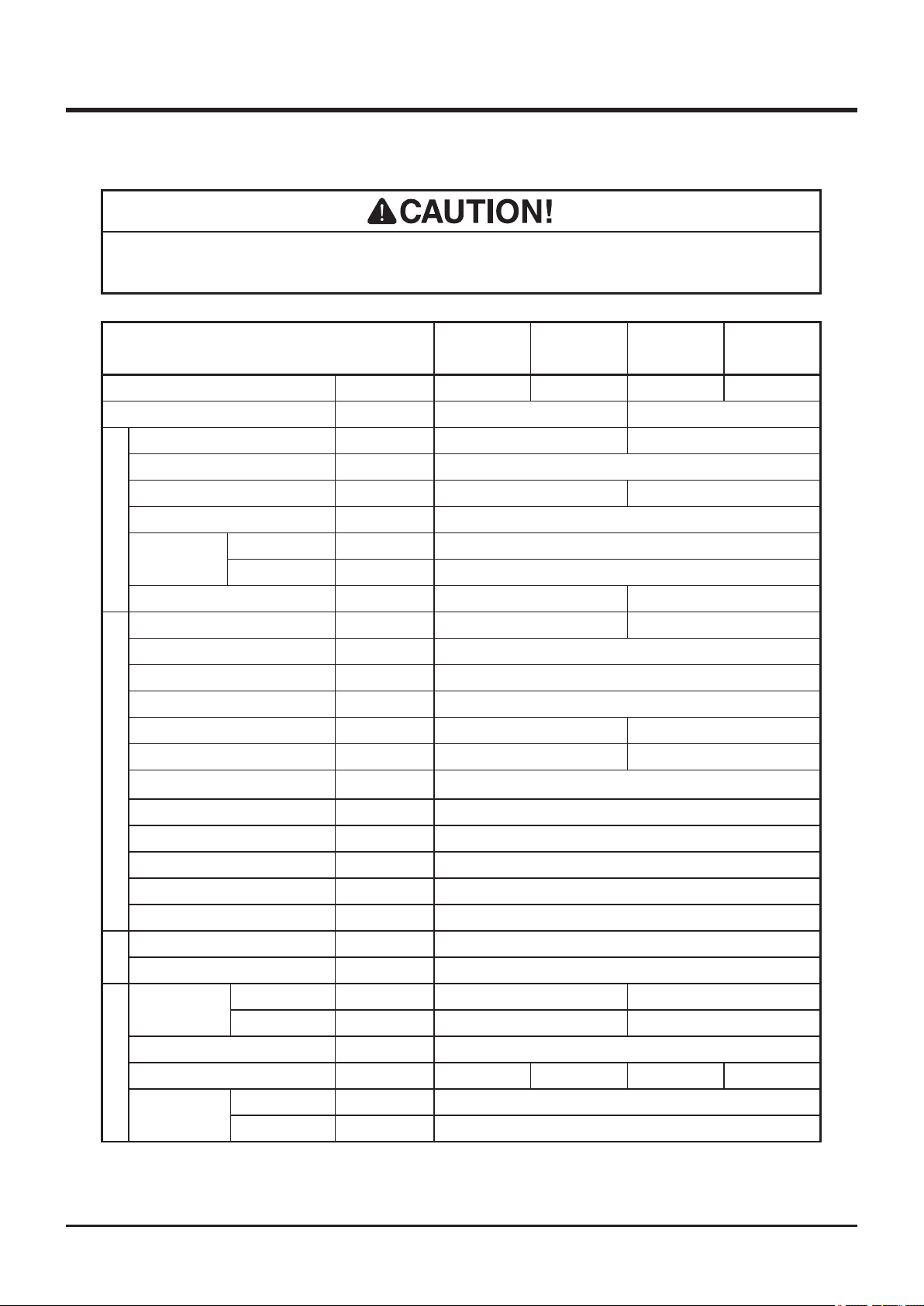
· Use this product properly after understanding its specications thoroughly.
Model and Type
Machine Mass kg
Mowing Rate m
Overall Length mm
Overall Width
Overall Height mm
Wheelbase
Dimensions
Tread
Front
Rear
Ground Clearance
mm
mm
mm
mm
mm
2
/h 7300
CMX227 CM226 CXM186 CM185
345 325 325 320
*1
1947 [1997]
*2
1020
860 [905]
*3
1300
860
800
130 110
7000
1947
840
Model Robin EH65DS Robin EH63DS
Type Air-cooled 4-cycle V-twin Gasoline
Cylinder (Bore×Stroke)
mm
Displacement cm
3
80X65
653
Maximum Output kw(PS)/rpm 16.4(22)/3600 13.4(18.3)/3600
Maximum Torque
Starter System Electric
Engine
N•m(kgf•m)/rpm
45.6(4.65) 43.3(4.42)
Fuel Automotive Unleaded Gasoline
Fuel Consumption
g/kW•h(g/PS•h)
310(230)
*1
Fuel Tank Capacity L 20
Ignition Contactless Magneto
Spark Plug NGK BPR5ES
Battery Type 38B19R
Electrical
Battery Capacity V/Ah 12/28
High
km/h
0 to 13.8 0 to 12.8
Speed
Low
km/h
0 to 7.7 0 to 7.2
Minimum Turning Radius m 1.8
Gradeability Degrees 25 15 25 15
Performance
Stability
Angle
*1 Estimated at the maximum speed with the auxiliary transmission in Low position (7.5km/h)
*2 [ ] indicates the Step Bumper model
*3 [ ] indicates the Extra Seat model
Left Degrees 30
Right Degrees 30
-15-
Page 25

3
Specications
Model and Type
Main Transmission
Auxiliary Transmission
Tires
Drive Train
Steering
Brakes Internally Expanding
Cutting Width
Cutting Height
Blade Type Free Knife & Stepped Stay
Number of Blades 2
Cutting System
Blade Drive Train Shaft Drive
*These specications are subject to change without notice.
Left AGR 4.00-7 (2PR) AGR 3.50-7 (2PR)
Right 17X8.00-8 (4PR) 16X7.00-8 (4PR)
mm
mm
mm
CMX227 CM226 CMX186 CM185
HST (Continuously
Constant Mesh
Rack and Pinion
Round Steering Wheel
975
0~150 (21 Steps) 0~130 (21 Steps)
Variable)
Contents of Tool Bag
No. Content Quantity Note
1 Operator's Manual 1 This Manual
2
4 Engine Service Tool 1
Operator's Manual for the Engine
1
for Servicing Engine
-16-
Page 26
Operation 4
Preparation
Pre-start up Inspection
Always perform an inspection before use.
Refer to the Maintenance Schedule (page 40) for the inspection schedule and procedure.
Checking and Filling Fuel
• Keep re and spark away when handling fuel.
• Always stop engine before refueling.
• Do not fill beyond the limit (bottom of the filler filter) so that fuel will not
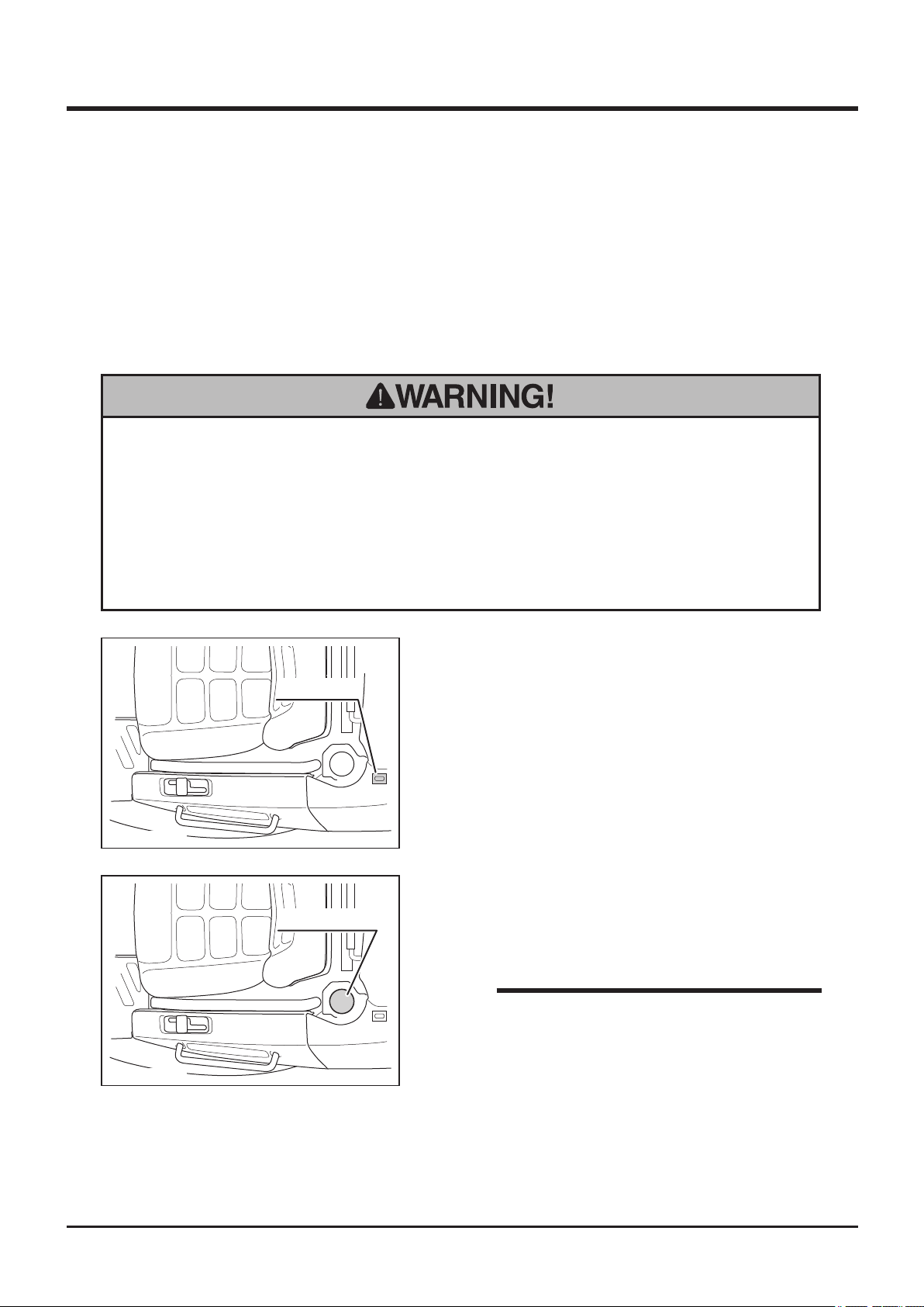
overow. In case fuel is spilt, wipe out immediately.
1. Check fuel gauge. If fuel level is low, ll fuel.
Fuel Gauge
5332M-0401-010E
2. Open fuel ller cap and ll fuel.
Fuel Filelr Cap
3. Put fuel filler cap back in place and close it
securely.
NOTE
• Fuel : Automotive Unleaded Gasoline
5332M-0401-020E
• Fuel Tank Capacity : 20L
-17-
Page 27
4
Operation
Adjusting Steering Wheel
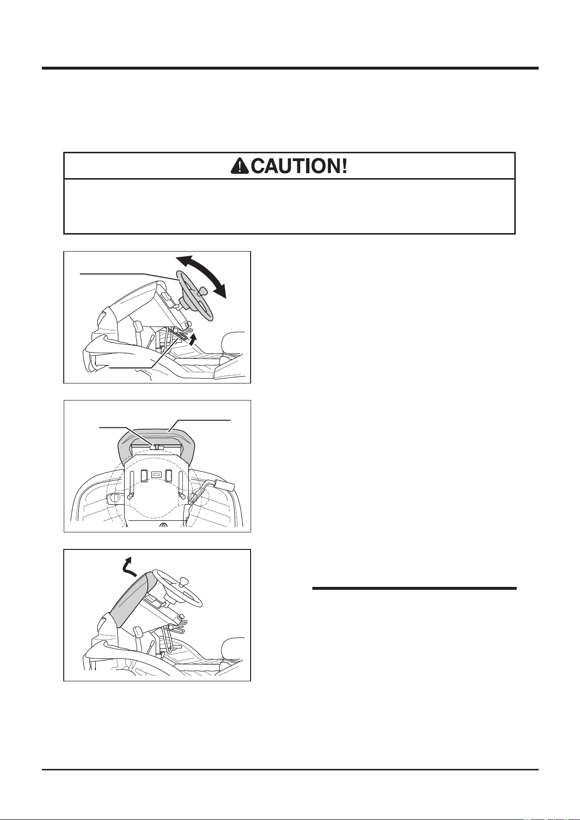
• After adjusting steering wheel, try moving steering wheel back and forth and up
and down to make sure it is securely locked in its position.
Steering Wheel
5332M-0401-030E
Latch
5332M-0401-040E
Tilt Lever
Front Cover
Adjusting Angle (Tilting)
1. Pull up tilt lever to adjust steering wheel
angle.
2. There are five positions for steering wheel
angle.
3. After adjusting angle, return tilt lever to lock
steering wheel securely.
Adjusting Height
1. Pull top edge of front cover to unlock latch.
5332M-0401-110E
2. Pull out front cover.
NOTE
• Inside of the front cover is made as tool
box. Use this box to store items such as
tools or substitute cutting blades.
-18-
Page 28
Operation 4
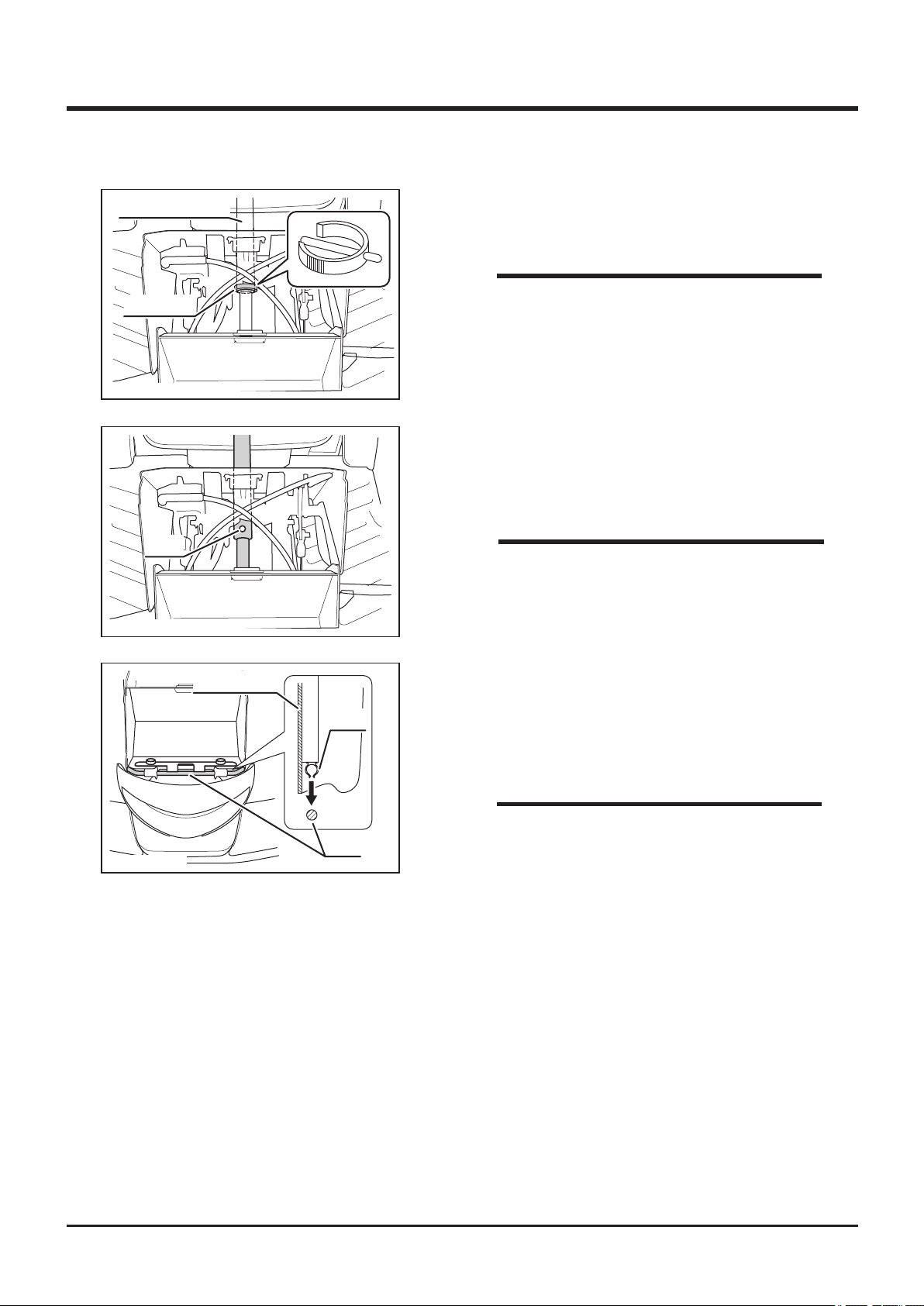
Steering Column
Fixing Pin
5332M-0401-120E
Hole
5332M-0401-130E
3. Remove fixing pin from steering column in
the front of machine.
NOTE
• If fixing ping is in the difficult direction to
remove, steer the steering wheel to change
direction of the pin so that the pin can be
easily removed.
4. Adjust steering wheel height in prefered
position. Line up holes on steering shafts and
insert pin.
NOTE
• Move steering wheel up and down to check
if the steering wheel is xed securely.
5332M-0401-140E
Front Cover
Clip
Rod
5. Raise steering wheel angle.
6. Fit clip on back side of front cover into the
rod.
7. Latch top edge of the front cover.
NOTE
• Pay attention not to catch the front cover by
the plate on both sides when installing front
cover.
-19-
Page 29
4
Operation
Adjusting Seating Position
• Beware of pinch points when adjusting seating position.
• After adjusting seat, try moving seat back and forth and up and down to make
sure it is securely locked in its position.
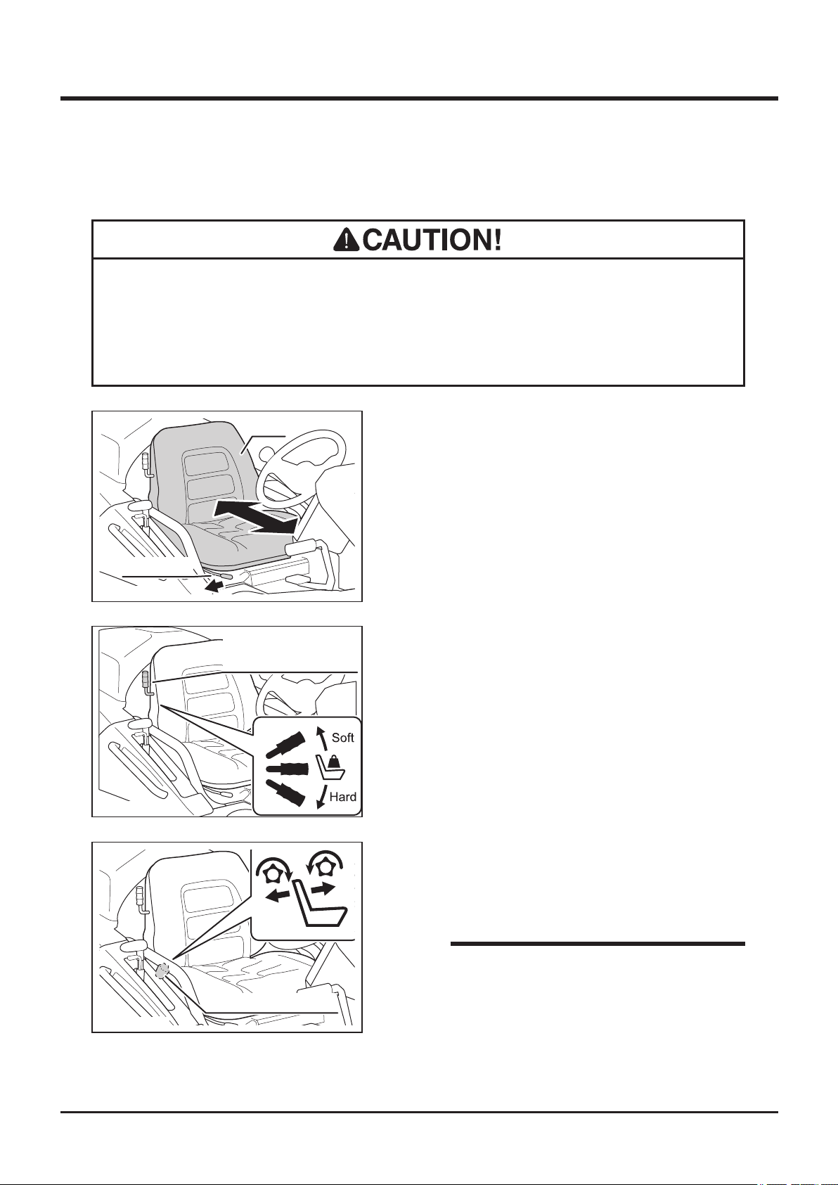
Slide Lever
5332M-0401-050E
5332M-0401-060E
Seat
Seat Suspension
Stiffness Adjust Lever
Sliding seat
1. Pull slide lever to the right to slide seat
forward or backward.
2. When seat is in a desired position, release
slide lever and lock seat securely.
Adjusting Stiffness
1. Move seat suspension stiffness adjust lever
to adjust desired seat stiffness.
5332M-0401-071E
Reclining Adjust Knob
Adjusting Reclining Angle
1. Rotate reclining adjust knob on the right of
seat to adjust reclining angle of the seat.
NOTE
• Do not ajust seat posision to the end and
recline the seat. The seat may contact with
rear cover. This may activate seat switch
and stop engine. Adjust seat in the range of
not contacting with rear cover.
-20-
Page 30
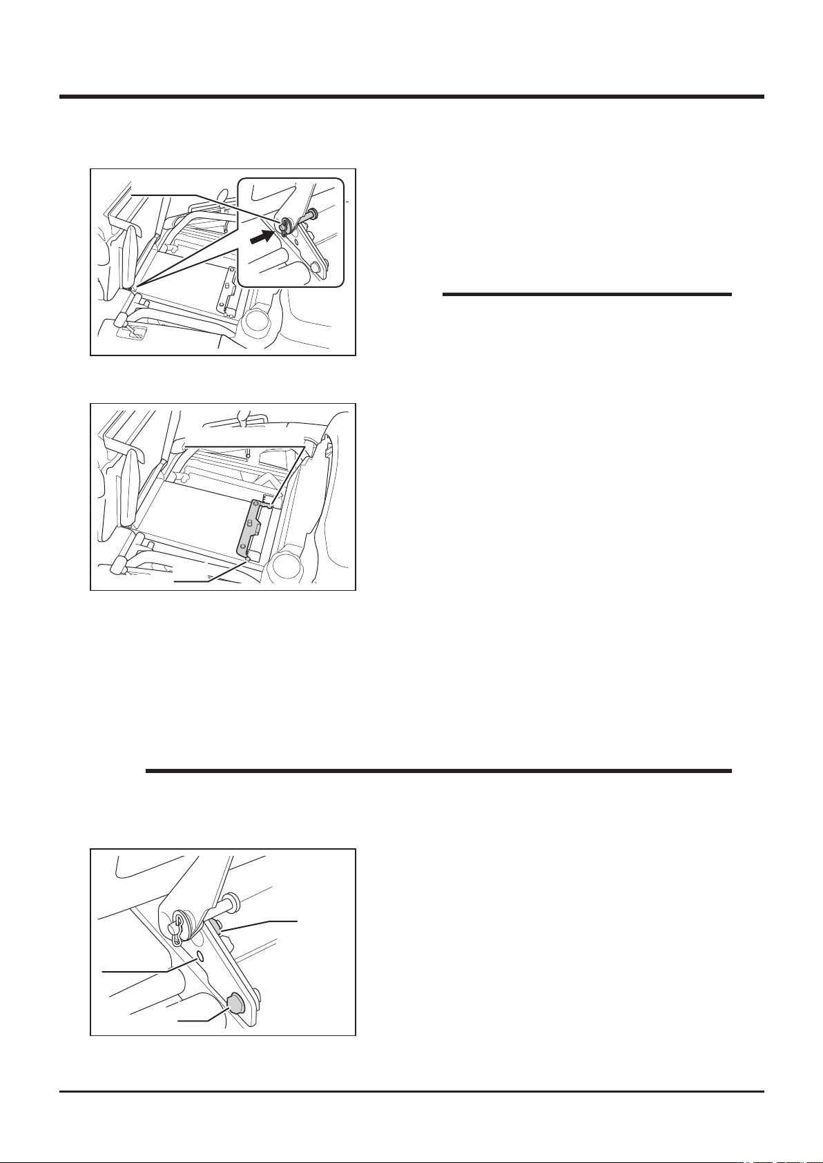
Operation 4
Safety Pin
5332M-0401-080E
5335M-0401-010E
Seat Switch Bracket
Bolts
Adjusting Height (Rear Part)
1. Slide seat to the rear-most position.
2. Pull up seat and push safety pin toward
inside to hold seat lifted.
NOTE
• Move seat and to check if the seat is locked
securely.
• Height can be adjusted in 4 levels.
3. Remove 2 bolts xing seat switch bracket.
4. Move seat switch bracket into desired
position and x with bolts rmly.
5. Pull safety pin back and lower the seat.
Adjusting Height (Front Part)
If the seat height is not high enought with the rear part of seat in the highest position, adjust
height of front the part of seat.
1. Pull up seat and push safety pin toward inside to hold seat lift up.
2. Adjust seat switch bracket in the highest position.
NOTE
• Seat switch bracket need to be in the highest position when addjusting height of
front part of seat.
3. Loosen nut (left and right) fixting hinge of
seat.
Nut
Front Hole
Bolt
5332M-0401-150E
4. Remove bolts on both sides.
5. Move seat so that front hole lines up with bolt
hole and x with bolt on both sides.
6. Tighten nuts.
7. Pull safety pin back and lower the seat.
-21-
Page 31
4
Operation
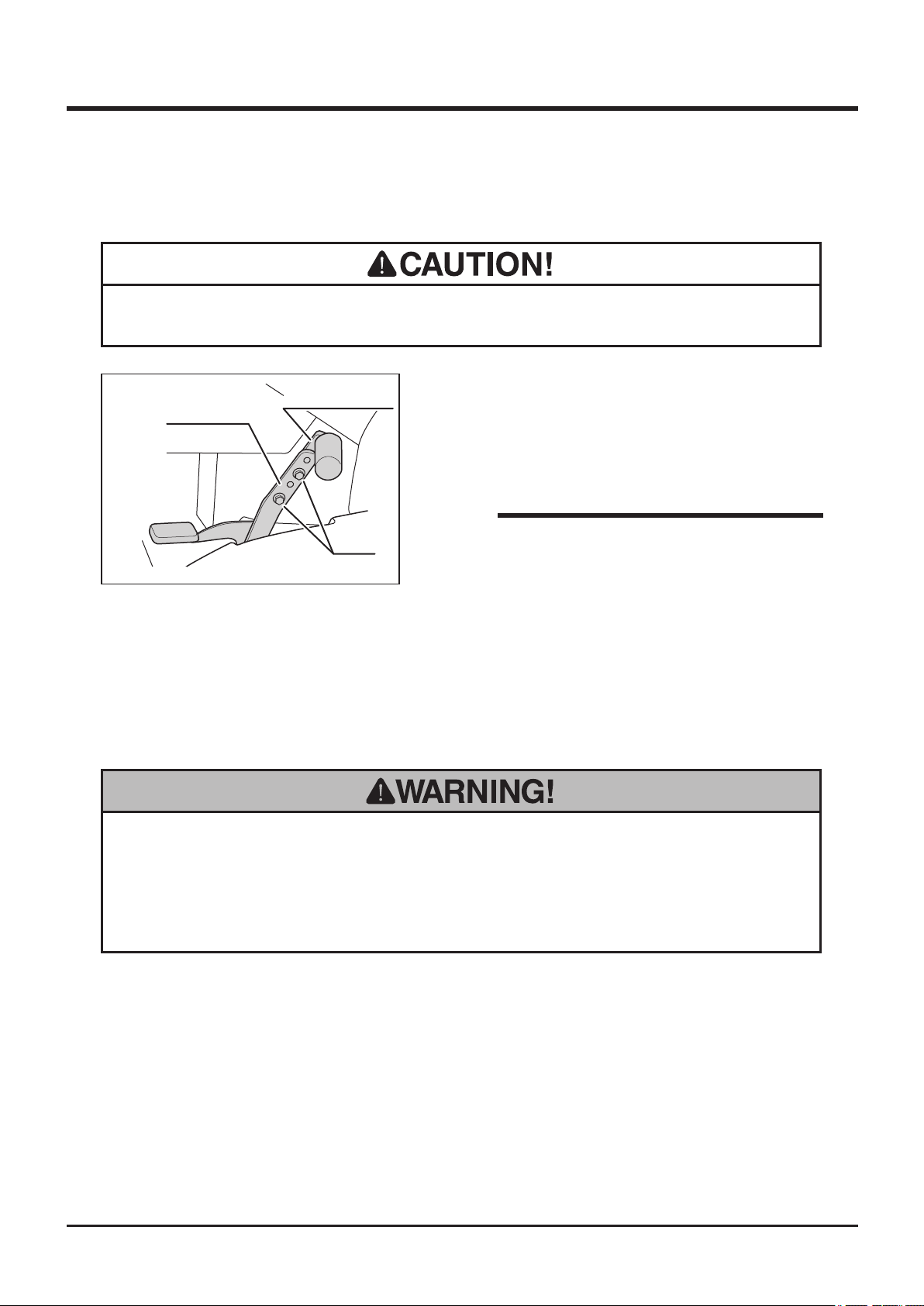
Adjusting Drive Pedal
• Always check if the drive pedal is xed rmly after adjusting.
5332M-0401-100E
Driving
Starting
Drive Pedal
Pedal (Forward)
Bolts
1. Remove two bolts fixing forward pedal with
drive pedal.
2. Adjust the pedal (forward) into the desired
position and x with bolts.
NOTE
• Drive pedal can be adjusted in 3 positions
and angle.
• Always start and run engine in a well ventilated place.
• Always stay on seat when starting engine. Never attempt to start engine away
from machine. Run over accident may result.
-22-
Page 32
Operation 4
• Do not turn main switch to [ (start)] position when engine is running. Starter
motor and/or engine may be damaged.
• Position throttle lever to [ (slow)] when starting.
• Do not turn the starter for more than 5 seconds. If the engine does not start,
turn main switch back to [ (off)] position and wait for 10 seconds or more
before attempting to start again.
• If engine does not start after starting procedure is performed several times, turn
off main switch and wait for 5 to 10 minutes and try again.
• Do not use this machine in temperatures above 40ºC or below -15ºC. This
machine cannot perform adequately in these temperature ranges. Using this
machine under such conditions may result in an accident or cause damage to
machine.
• In the winter or cold climate, warm up engine thoroughly before driving
machine. A cold engine delivers poor performance, which may result in an
accident. It also causes excessive wear.
• Do not use this machine in dusty places such as desert. Dust may clog air
cleaner or enter engine, which may reslt in loss of performance and an accident.
It also causes excessive wear.
• Do not use this machine in the altitude above 1500m (4920ft.) in its original
configuration. This machine cannot perform adequately above that altitude.
Using this machine under such conditions may result in an accident or cause
damage to machine. If you need to use this machine above that altitude, contact
your CANYCOM representative.
-23-
Page 33
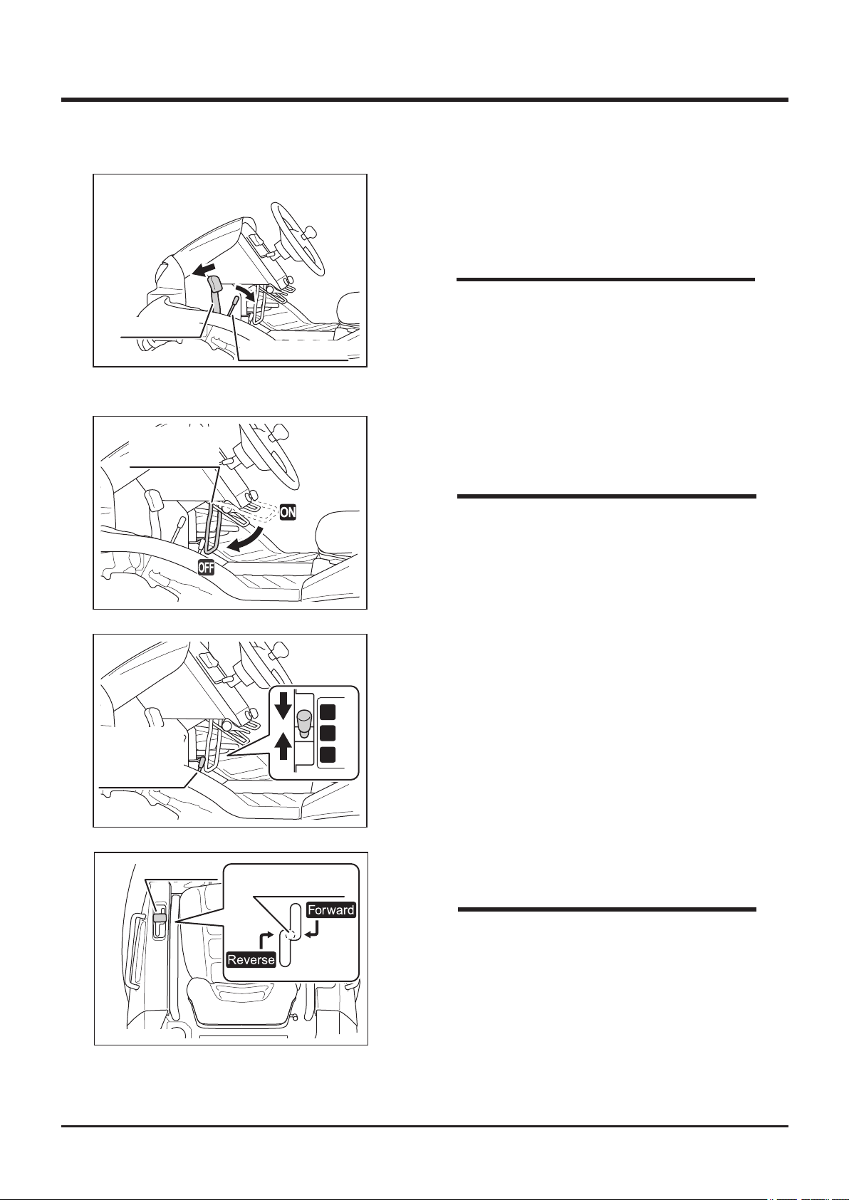
4
5332M-0402-010E
Brake Pedal
Operation
1. Make certain brake pedal is depressed and
locked. If it is not, depress brake pedal and
pull lock lever to lock it.
NOTE
• Safety feature: engine cannot be started
unless brake pedal is depressed.
Brake Lock Lever
Cutting Rotery
Clutch Lever
5332M-0402-020E
Auxiliary
Transmission
Shift Lever
5332M-0402-030E
2. Make sure cutting rotary clutch lever is in
[OFF] position.
NOTE
• Safety feature: engine cannot be started
unless cutting rotary clutch lever is in [OFF]
position.
3. Make certain auxiliary transmission shift
lever is in [N (neutral)] position.
L
N
H
Drive Lever
5332M-0402-040E
4. Make certain drive lever is in nutral position.
Nutral Position
NOTE
• Drive lever returns to neutral position when
brake pedal is fully depressed.
-24-
Page 34
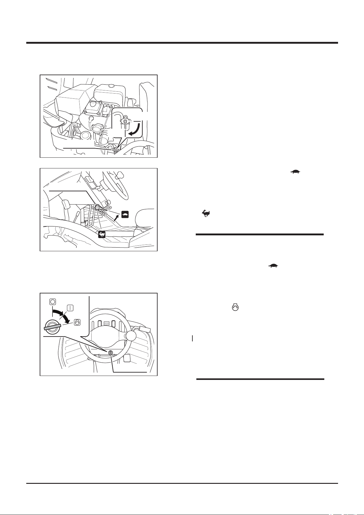
Fuel Cock
5332M-0402-060E
Operation 4
5. Open engine hood (see page 51). Open fuel
cock.
Close
Open
6. Make sure throttle lever is in the [ (slow)]
Throttle Lever
5332M-0402-080E
5332M-0402-070E
position. In the cold weather below 10
degrees celsius when engine revolution is
not stable, position throttle lever 1/3 toward
the [ (fast)] position.
NOTE
• This machine is equipped with the auto-
choke system and may start more easily
with throttle lever in the [ (slow)] posi-
tion.
7. Insert ignition key into main switch.
8. Turn key to [ (start)] position to start
engine. Release key immediately after
engine starts. Key automatically returns to
[ (ON)] position.
9. Run engine without load for about 5 minutes
to warm up.
Main Switch
NOTE
• Avoid frequent starting. Once engine starts,
run it for a while to charge battery.
• Drive machine gently in the first week (40
to 50 hours) of operation after purchase for
breaking-in.
-25-
Page 35
4
Operation
Driving
• Always wear protective footwear, long trousers, hardhat, safety glasses and
ear protection when operating or servicing the machine. Proper clothing will
minimize the chance of injury. Do not operate the equipment if you have long
hair, loose clothing, or jewelry; all of which may get tangled in moving parts. Do
not operate the machine barefoot or with open sandals.
• Do not allow bystanders to come near machine when driving.
• Always make certain of the safety of your surroundings before driving; start
slow.
• Always make certain of the safety of your surroundings before turning
• Do not make sudden starts, acceralation, change of speed, change of direction,
or stop. Do not turn at speed. Avoid sudden maneuvers; this may cause the
operator to fall or to be thrown, or machine to tip over.
• Do not operate drive pedal and drive lever simultaneously.
• Do not turn the key to [ (off)] position while traveling.
• Do not operate drive pedal or drive lever when brake is locked with parking
brake lock lever. It can wear out brake.
-26-
Page 36
Auxiliary
Transmission
Shift Lever
5332M-0402-100E
Throttle Lever
Operation 4
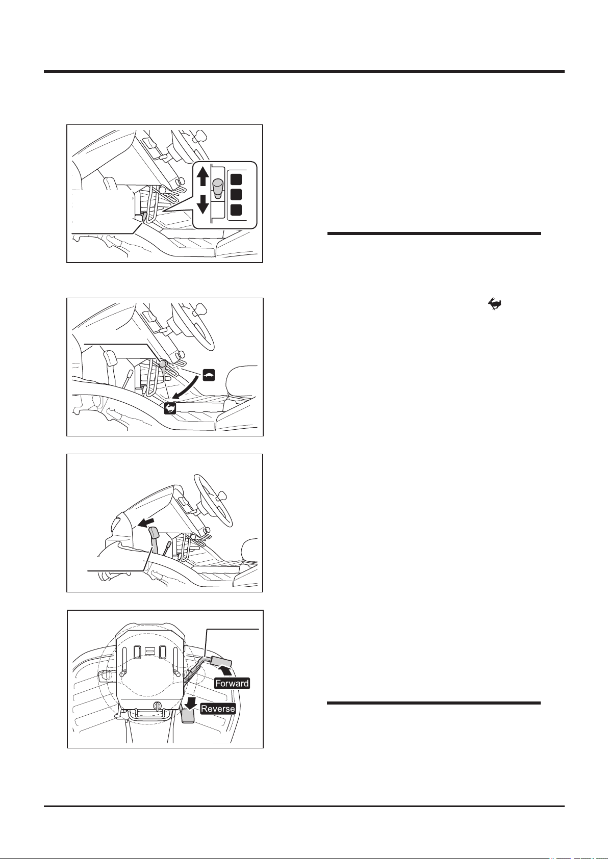
1. M ake cer t a i n of th e sa f e ty o f yo u r
surroundings.
2. Move auxiliary transmission shift lever to
L
N
H
either [H (high speed)] or [L (low speed)]
position.
NOTE
• See Specications (page 15) for the speed
range in either gear position.
3. Move the throttle lever toward [ (fast)]
position to increase engine speed.
5332M-0402-110E
Brake Pedal
5332M-0402-120E
Drive Pedal
4. Depress brake pedal to release brake pedal
lock.
Driving with Drive Pedal
5. Depress gradually the forward or reverse side
of drive pedal to move in the corresponding
direction.
NOTE
• Speed can be adjusted continunously by the
5332M-0402-130E
position of drive pedal.
-27-
Page 37
4
Operation
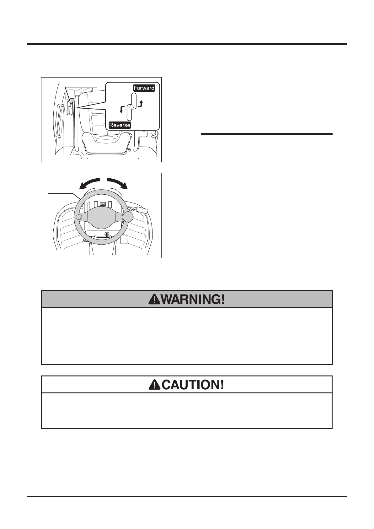
Drive Lever
5332M-0402-140E
Steering
Wheel
5332M-0402-150E
Driving with Drive Lever
5. Move drive lever gra dually fo rward or
backward to move in the corresponding
direction.
NOTE
• Speed can be adjusted continunously by the
position of drive lever.
6. Turn steering wheel to turn.
Stopping
• Do not make a sudden stop. Operator may be thrown off, or machine may skid
or tip over.
• Always park on a rm, level place. Never park on a potentially dangerous place.
• Do not hold drive lever and depress brake pedal at the same time. Or, do not
depress drive and brake pedals at the same time. HST may be damage.
-28-
Page 38
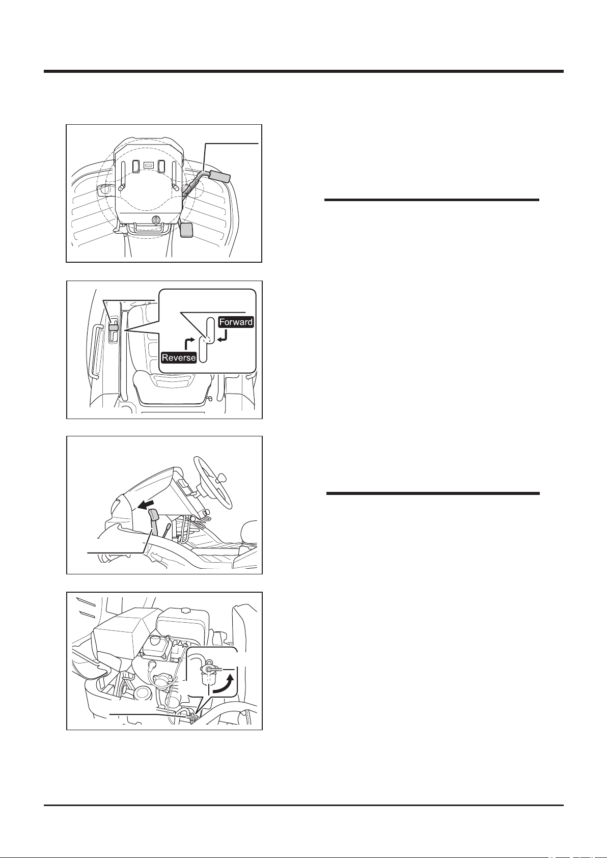
Operation 4
5332M-0402-160E
Drive Lever
5332M-0402-040E
Drive Pedal
Nutral Position
When Driving with Drive Pedal
1. Gradually return drive pedal to slow down.
2. Take foot off drive pedal.
NOTE
• Drive pedal automatically returns to neutral
when released.
When Driving with Drive Lever
1. Gradually return drive lever to nutral position
to slow down.
2. Release hand off drive lever.
Brake Pedal
5332M-0402-120E
5332M-0402-090E
3. Depress brake pedal to stop machine
completely.
NOTE
• When brake pedal is depressed, drive lever
returns to neutral position.
4. Open engine hood and close fuel cock. Close
engine hood.
Close
Open
Fuel Cock
-29-
Page 39
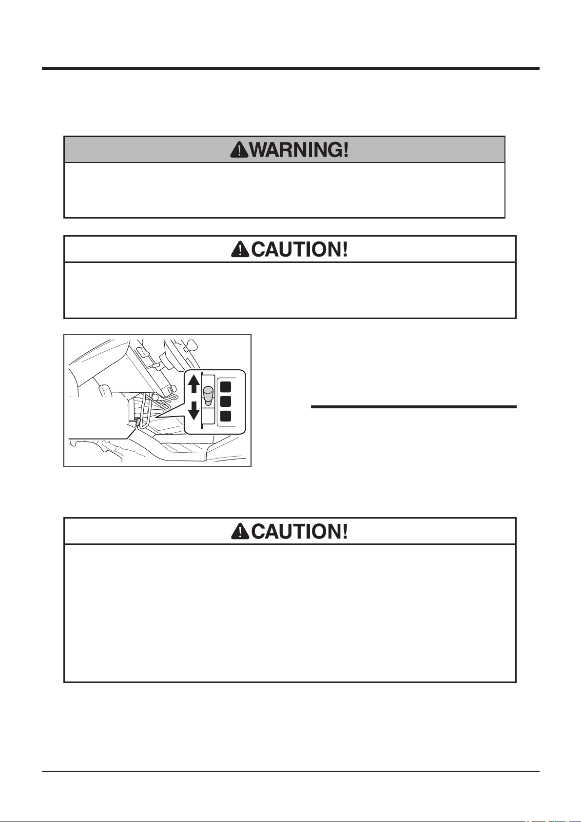
4
Operation
Shifting
• Always shift gears rmly. When transmission is not rmly shifted, it may jump
out of gear, resulting in loss of control of machine.
• Always stop machine to shift gears. Shifting gears while machine is in motion
can damage transmission.
1. Stop machine.
2. Move auxiliary transmission shift lever to [H
(high speed)] or [L (low speed)] position rmly.
L
Auxiliary
Transmission
Shift Lever
5332M-0402-100E
Shifting Between 2WD and AWD
• Always stop machine to shift between 2WD or AWD (all-wheel-drive) modes.
Shifting gears while machine is in motion can damage transmission.
• Use 2WD mode under normal condition.
N
H
NOTE
• See Specications (page 15) for the speed
range in either gear position.
(CMX227 and CMX186)
• Pay attention to the minimum turning radius in AWD mode. In AWD mode,
minimum turning radius is greater than that in 2WD mode.
-30-
Page 40
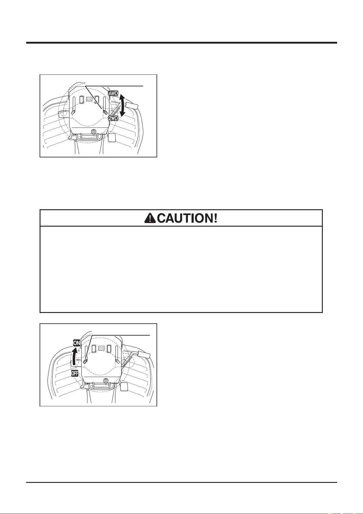
Operation 4
2WD/AWD Shift Lever
1. Stop machine.
2. Move 2WD/AWD shift lever to [2WD] or
[AWD] position rmly.
5332M-0402-170E
Locking Differential
Differential can be locked to minimize slipping o slippery surface.
• Always stop machine to operate differential lock lever. Operating differential
lock lever while machine is in motion can damage differential.
• Keep differential lock in [OFF] position under normal running condition.
Differential may be damaged.
• Do not turn machine when differential lock is in [ON] position.
Differential Lock Lever
1. Move differential lock lever to [ON] position.
2. Move auxiliary transmission shift lever to [L
(low speed)] position.
3. Drive slowly out of the slippery area.
5332M-0402-180E
-31-
Page 41
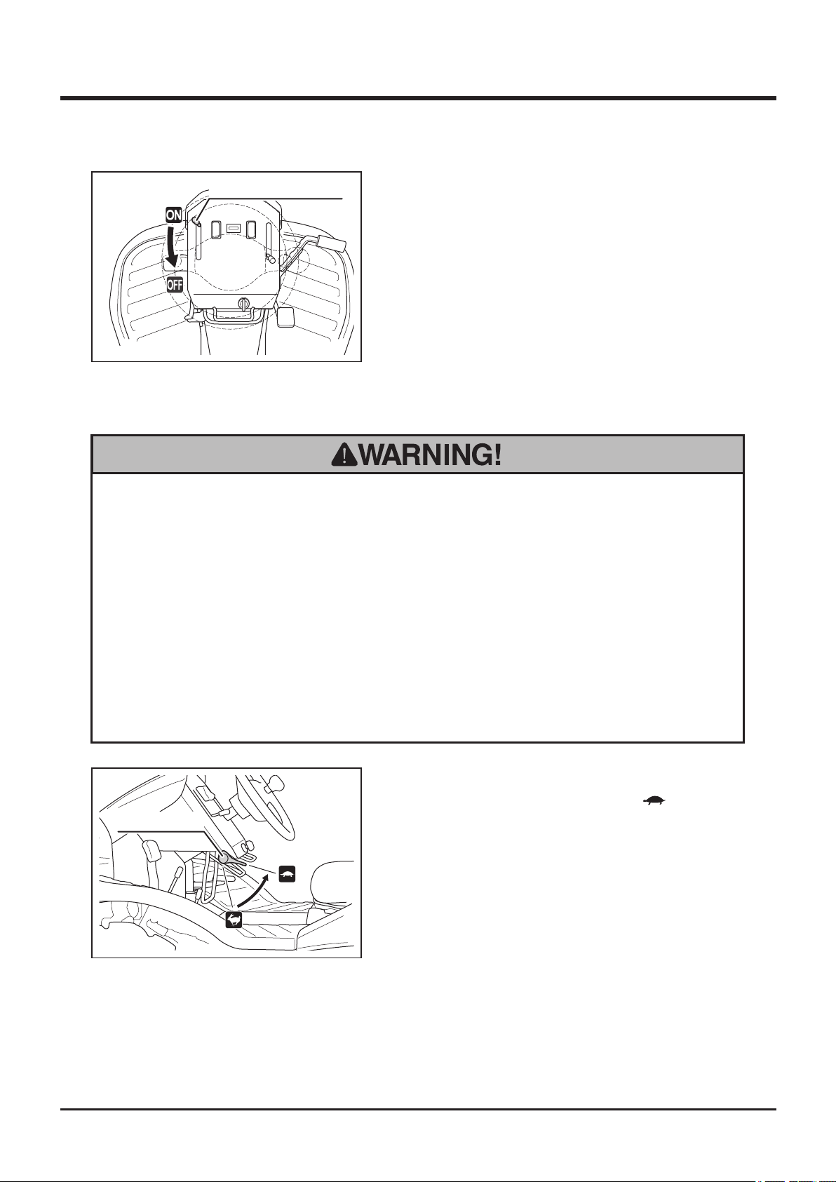
4
Operation
Differential Lock Lever
5332M-0402-190E
4. Once machine is out of the slippery area,
stop and move differential lock lever to [OFF]
position.
Parking
• Always park on a rm, level place. Never park on a potentially dangerous place.
• Avoid parking on a slope. Never park on a slope with an incline of 10 degrees
or steeper. If it is absolutely necessary to park machine on a slope less than
10 degrees, make certain to apply parking brake rmly and block wheels with
chocks.
• Apply brake and remove key when parking.
• Do not park near combustibles.
1. Stop machine.
2. Move throttle lever toward [ (slow)] to slow
Throttle Lever
5332M-0402-200E
engine speed.
-32-
Page 42
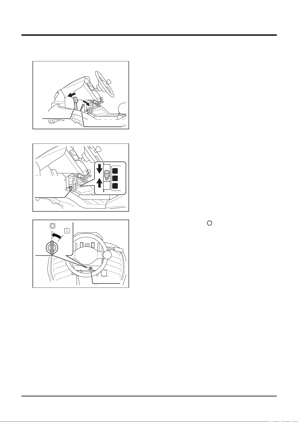
Brake Pedal
5332M-0402-010E
Auxiliary
Transmission
Shift Lever
Operation 4
3. Depress brake pedal and pull brake lock
lever to lock brake pedal in depressed
position.
Brake Lock Lever
4. Move auxiliary transmission shift lever to [N
(neutral)] position.
L
N
H
5332M-0402-030E
5332M-0402-210E
5. Turn main switch to [ (off)] to stop engine.
Remove ignition key.
Main Switch
-33-
Page 43
4
Operation
Working
Inspecting Cutting Blade
Inspect cutting blade before work. Refer to Cutting Blades (page 65) for inspection
procedure.
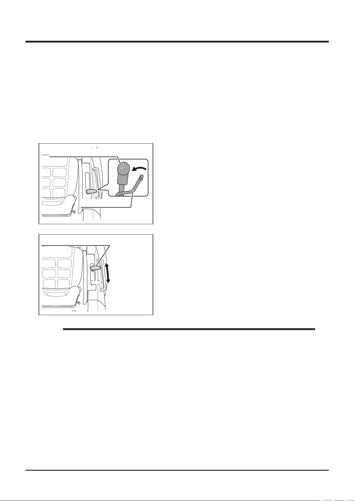
Adjusting Cutting Height
Cutting Height Adjust Lever
Cutting Height Lock
5335M-0403-010E
Cutting Height Adjust Lever
5332M-0403-020E
1. Grab cutting height lock to unlock cutting height
adjust lever.
2. With lock button pulled up, move cutting
height adjust lever to a desired position.
3. Release lock to lock cutting height adjust
lever.
NOTE
• Cutting Height Range: 0mm - 150mm (CMX227, CM226)
0mm - 130mm (CMX186, CM185)
• Cutting Height indicated on the side of the adjust lever is for reference purpose
only; actual cutting height may vary due to the condition of ground or brush, and
other factors.
-34-
Page 44
Operation 4
Cutting
• Never place any part of body under cutting blade shield.
• Always wear protective footwear, long trousers, hardhat, safety glasses and
ear protection when operating or servicing the machine. Proper clothing will
minimize the chance of injury. Do not operate the equipment if you have long
hair, loose clothing, or jewelry; all of which may get tangled in moving parts. Do
not operate the machine barefoot or with open sandals.
• Do not allow bystanders to come near machine when cutting.
• Rotating cutting blades can throw stones or debris and cause injuries and
damages to nearby people, animals, crops, buildings, automobiles, etc. Pay
attention to the safety of surroundings and plan ahead when cutting.
• Never attempt to cut with cutting blade shield open.
• When cutting, drive forward. Machine is intended to cut brush while moving
forward, and this best prevents stones and debris from being thrown.
• Turn cutting rotary clutch to [ON] only when cutting. Keep it in [OFF] position all
the other times.
• Never attempt to cut brush on the edge of a ditch or bank. Shoulder of the ditch
or bank may collapse. Pay special attention after heavy rain or earthquake.
-35-
Page 45
4
• Inspect the work site beforehand; inspect terrain and locate holes, drops, or
obstacles. Also inspect overhead obstacles such as the branches of a tree. Pay
special attention when working near these areas.
• Do not use this machine on an incline steeper than 25 degres for the CMX 227/
CMX186 or 15 degrees for the CM226/CM185.
• Always stay on machine when working.
• Make sure air intake for cooling is not clogged or blocked. If it is clogged or
blocked, it causes overheating, resulting in damages to machine.
Operation
• When working in a dusty area, clean air cleaner element twice a day. Dirty air
cleaner element results in poor starting, poor performance, or short life.
• When a cutting blade is broken, replace it and the other blade with a new pair. A
broken blade causes excessive vibration, which damages machine.
• When something is tangled to cutting blade, stop engine immediately and
remove the tangled object. Such object causes excessive vibration, which
damages machine.
• Always clean cutting blades and cutting blade stay after every use ( see page
75). Remained foreign object may solidied or corrode and make cutting blades
hard to remove.
-36-
Page 46
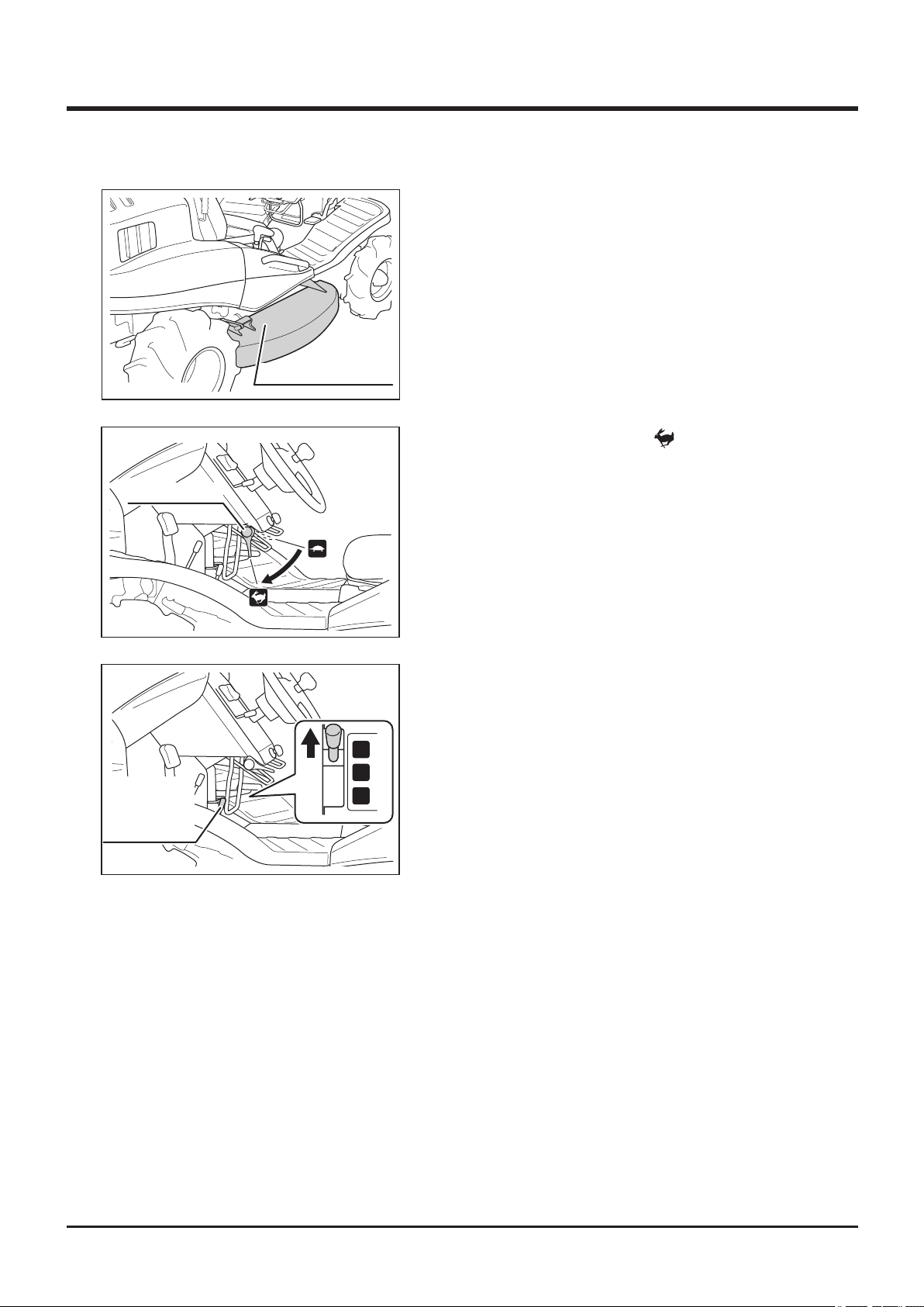
Operation 4
5332M-0402-110E
Throttle Lever
1. Make sure cutting blade shield is closed.
5332M-0403-060E
Auxiliary
Transmission
Shift Lever
Cutting Blade Shield
2. Turn throttle lever to [ (fast)] position to
raise engine speed.
3. Move auxiliary transmission shift lever to
[L (low speed)].
L
N
H
5332M-0403-070E
-37-
Page 47
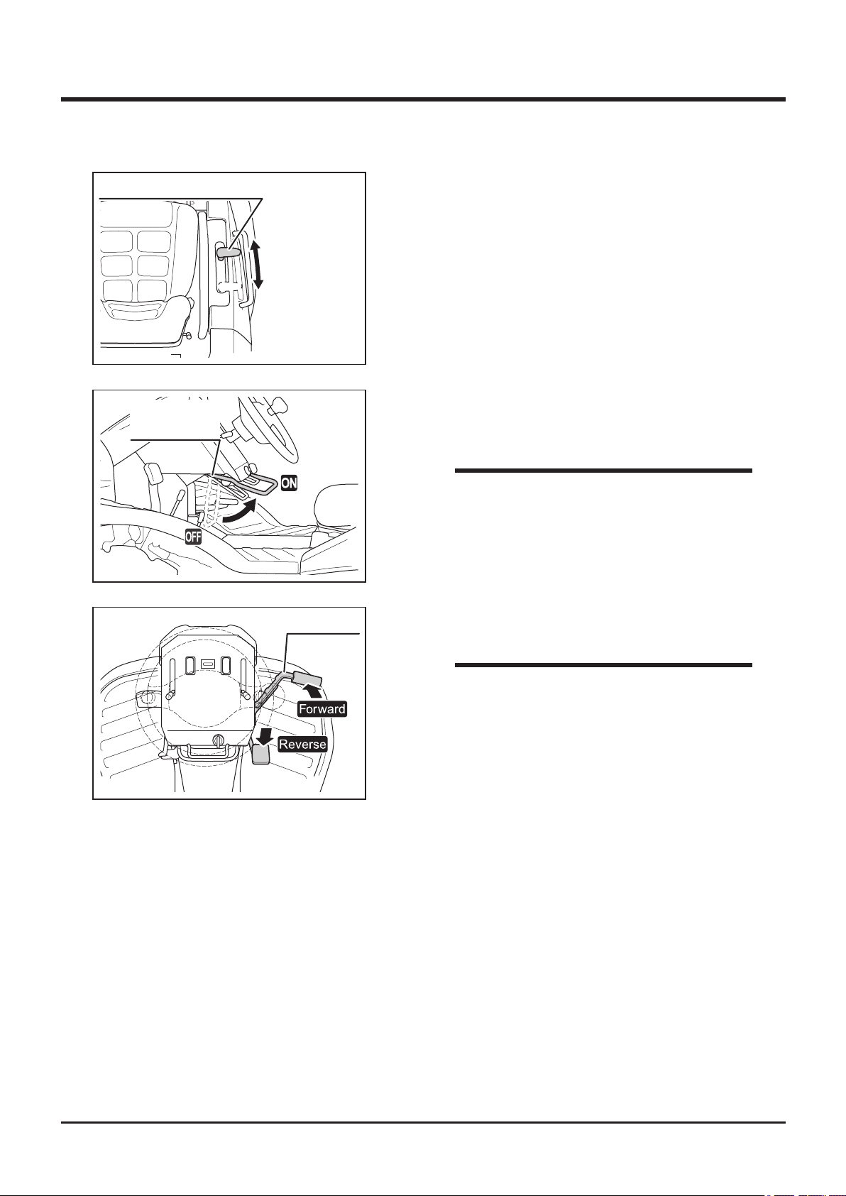
4
Operation
Cutting Height Adjust Lever
5332M-0403-020E
Cutting Rotary
Clutch Lever
5332M-0403-080E
4. Move cutting height adjust lever to a desired
height.
5. Move rotary clutch lever to [ON] to start
cutting blade.
NOTE
• Safety feature: engine stops automatically if
operator leaves seat while cutting blade is
rotating.
5332M-0402-130E
Drive Pedal
6. Drive machine forward to cut.
NOTE
• When cutting with this machine for the rst
time, start on a flat surface. Drive slowly
and in an overlapping pattern.
• If load to cutting blade is high, drive slowly,
or cut twice.
-38-
Page 48
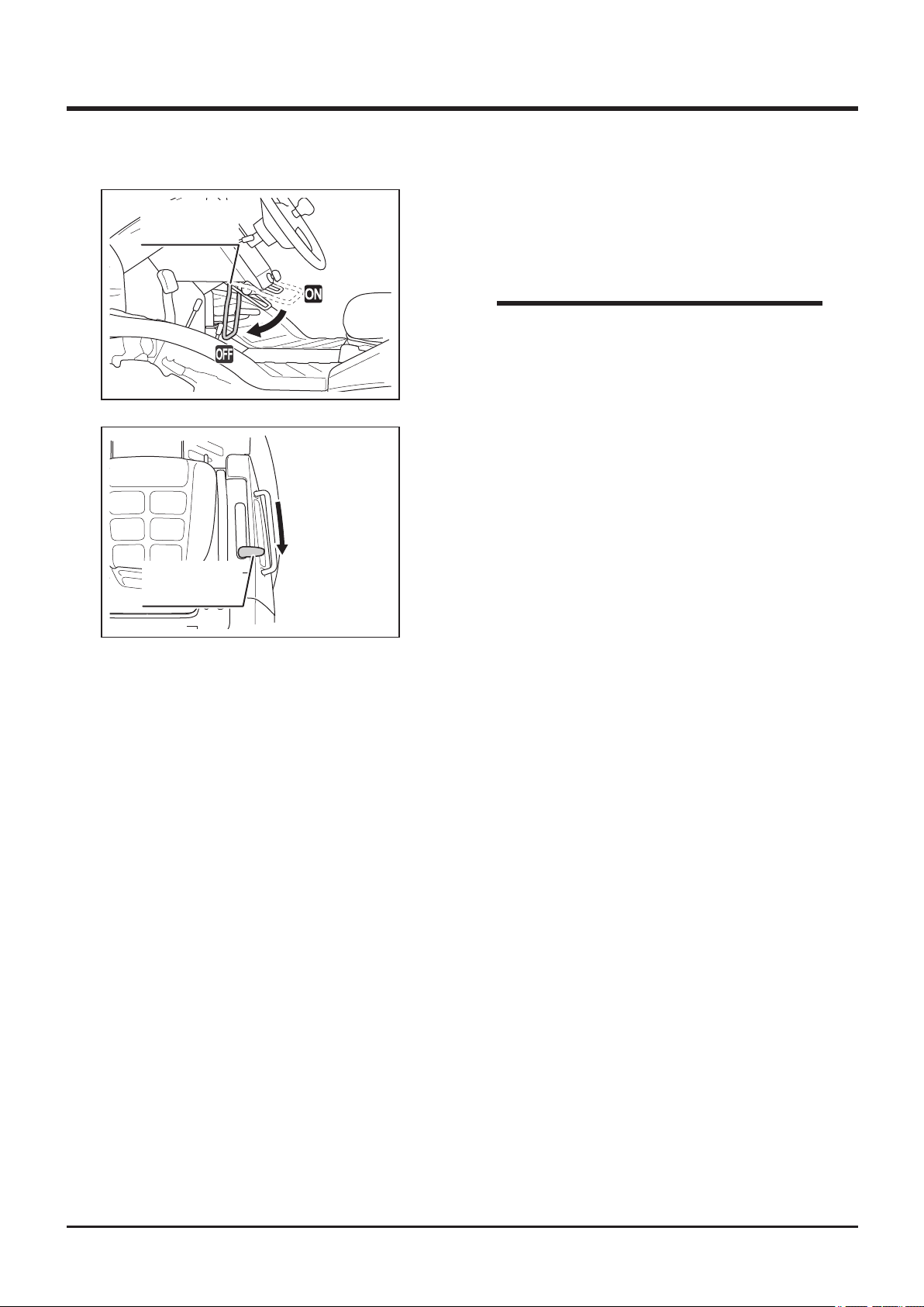
Operation 4
Cutting Rotery
Clutch Lever
5332M-0402-020E
Cutting Height
Adjust Lever
5332M-0403-090E
7. Move cutting rotary clutch lever to [OFF] to
stop cutting blade.
NOTE
• Moving cutting rotary clutch lever to [OFF]
applies brake on cutting blade to stop.
8. Move cutting height adjust lever to the
highest position.
-39-
Page 49
4
Operation
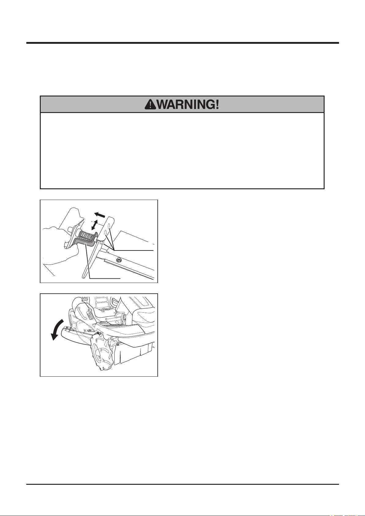
Adjusting Cutting Blade Shield
• Always stop engine when adjusting cutting blade shield. It may cause serious
injury if you open cutting blade shield when blades are rotating.
• Never attempt to work if cutting blade is unlocked. Also never attempt to work
if cutting blade shield is open upward.Thrown stones or debris may cause
injuries to nearby people.
Opening shield to the side
A
B
1. Squeeze lock lever as shown (A).
2. Keep lock lever squeezed and move shield
5335M-0505-090E
5335M-0505-080E
Lock Lever
Lock Positions
(B) to one of three lock positions.
3. Release lock lever at the selected lock
pos ition so that the pi n o n l ock lever
positively ts into the hole at lock position.
-40-
Page 50
Maintenance 5
Clean Oil pan
Maintenance Schedule
• Follow the scheduled maintenance as described below. Failure to do so may
result in mechanical or property damage, injury or death.
Engine
Daily Inspection
• Engine Oil - to be clean and at the correct level.
• Air Cleaner Element - to be clean and free of damage.
• Leaks - No fuel or oil leaks to be found.
• Bolts, Nuts, Fasteners - not to be loose or missing.
• Sound, Vibration - No abnormal noise or excessive vibration.
Scheduled Maintenance
Items
Clean and check fastenrs
Check and fill oil
Clean air cleaner element
Change oil First time:20 hours. Every 50 afterward
Clean spark plugs Every 100 hours
Replace fuel strainer Every 200 hours
Replace air cleaner element
Check and adjust spark plug gap
Replace oil filter
Check and adjust tappets Every 300 hours (do more frequently in dusty place)
Remove carbon deposit from cylinder head Every 500 hours (do more frequently in dusty place)
Every 500 hours (clean more frequently in dusty place)
Clean carburator Every 500 hours (clean more frequently in dusty place)
Perform valve lapping Every 500 hours (clean more frequently in dusty place)
Replace fuel hose Every two years
Overhaul 1000 hours (contact Canycom representative for overhaul)
(clean more frequently in dusty place)
(clean more frequently in dusty place)
(clean more frequently in dusty place)
(contact Canycom representative for placement)
(contact Canycom representative for placement)
First time:50 hours. Every 200 afterward
(contact Canycom representative for
Frequency
Every 8 hours (daily)
Every 8 hours (daily)
Every 8 hours (daily)
Every 200 hours
Every 200 hours
placement)
-41-
Page 51
5
Maintenance
Chassis
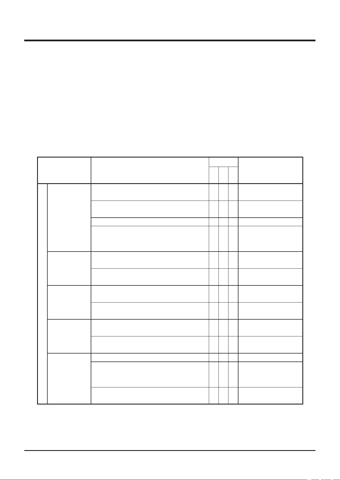
• Perform a pre-startup inspection (PSI) before each use, a monthly inspection once a
month, and a yearly inspection once a year.
• Some maintenance procedures described below may require special knowledge
or tools and instruments. Contact your CANYCOM representative to perform such
procedures.
Schedule
Item Description
Tires shall be inflated to the specified
pressure.
Tires and wheels shall be free of crack,
Tires
Transmission
Auxiliary
Drive Train
Transmission
Front Axle
HST
damage, or uneven wear.
Wheel bolts shall not be loose or missing.
Wheel bearings do not exhibit excessive play
and no irregular noise or overheating shall
be observed.
Irregular noise or overheating shall not be
observed when moving forward or backward.
There shall not be oil leaks in or around
transmission.
Transmission can be shifted to either position
positively and performs normally.
Lever shall not be loose or have excessive
play.
Irregular noise or overheating shall not be
observed when traveling.
There shall not be oil leaks in or around front
differential case or knuckles.
HST shall perform normally.
Hydraulic fluid shall be filled to a proper
level and shall be clean and free of dirt or
contamination.
Lever or pedal shall not be loose or have
excessive play.
PSI
Mon
√ √ √
√ √
√ √ √
√ √
√ √
√ √
√ √
√ √
√ √
√ √
√ √ √
√ √
√ √
Year
Page 59
Page 61
Note
-42-
Page 52
Maintenance 5
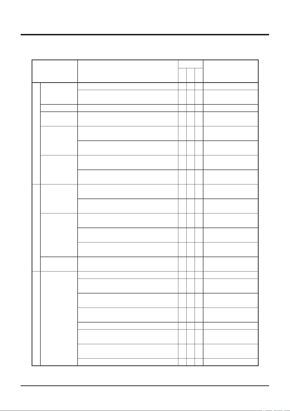
Item Description
Belt tension shall be properly adjusted.
V-belt
Brake Brake shall work properly.
Parking Brake
Steering
Drive Train
Rods, Links,
and Wires
Chassis,
Frame
Body Panels
Body, Chassis, Safety Devices
Labels
Cutting
System
Cutting System
Belt shall be free of damage or excessive
wear.
Parking brake shall be able to hold the
machine on a 20-degree slope.
Turn steering wheel right and left; front
wheels shall turn accordingly.
Steering can be adjusted in 5 positions and
locked securely.
Rods, links, and wires in linkage shall be free
of deformation or damage.
Connections shall be free of looseness,
excessive play, or missing cotter pins.
Shall be free of cracks, deformation, or
corrosion.
Fastening bolts or nuts shall not be loose or
missing.
Shall be free of cracks, deformation, or
corrosion.
Doors and lids shall open, close, and lock
properly.
Fastening bolts or nuts shall not be loose or
missing.
Warning labels and instruction plates shall be
clean, legible, and free of damage.
Blades shall be free of cracks or damage.
Blade mounting pins and wave washers shall
be free of cracks or damage.
Cutting blade shield shall be free of cracks or
damage.
Skirts on cutting blade shield shall be free of
cracks or damage, and shall not be missing.
Belt tension shall be properly adjusted.
Belt shall be free of damage or excessive
wear.
When activated, cutting blade brake shall
stop cutting rotary.
Greasing points shall be properly greased.
Schedule
PSI
Mon
Year
√ √
√ √
√ √ √
√ √
√ √
√ √
√ √
√ √
√ √
√ √ √
√ √
√ √
√ √ √
√ √ √
√ √ √
√ √ √
√ √ √
√ √ √
√ √ √
√ √ √
√ √ √
√ √
Note
Page 64
Page 65
Page 65
Page 68
Page 68
Page 68
Page 46, 47
-43-
Page 53
5
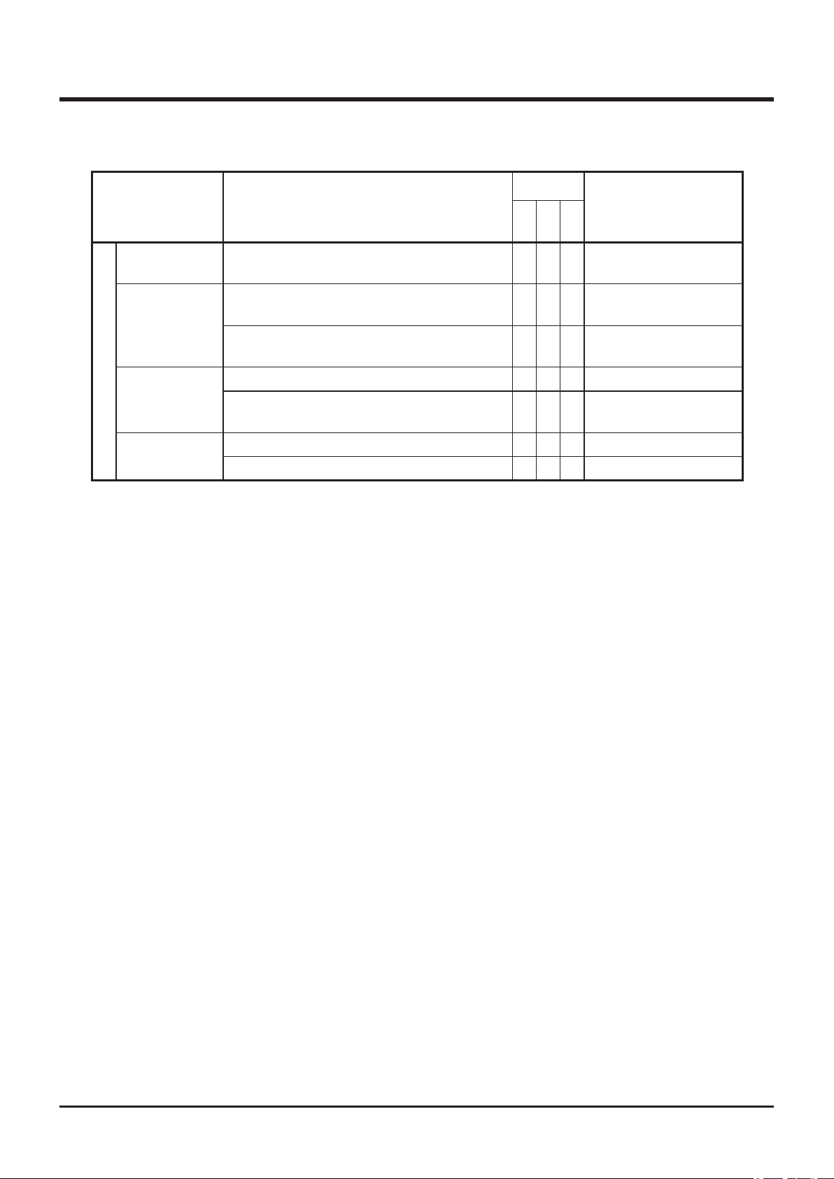
Charging
System
Battery
Head Lamp
Tail Lamp *
Electrical System
Wiring
Maintenance
Item Description
Charging system shall charge battery.
Battery fluid (electrolyte) shall be of proper
level.
Terminals shall be free of looseness or
excessive corrosion.
Head and tail lamps shall work.
Lamp lens shall be free of cracks or chipping
1
and water shall not be in the lamp.
Connections shall not be loose.
Wiring shall be free of damages.
Schedule
PSI
Mon
Year
√
√ √
√ √
√ √ √
√ √
√ √
√ √
Note
Page 71
*1 CMX227 only.
-44-
Page 54

Maintenance 5
List of Fluids and Lubricants
Item Schedule Grade Cap.
Fuel As needed. Automotive Unleaded Gasoline 20 L
Engine Oil Fill
Inspect daily. Fill as needed.
Change
Initially - After 20 hours of use.
Every 50 hours afterwards.
Transmission Oil Change
Initially - After 50 hours of use.
Every 500 hours afterwards.
Front Axle Oil*1 As needed. Gear Oil
HST Fluid As needed. Gasoline Engine Oil
Cutting Rotary
Grearbox Oil
Battery Electrolyte Fill
*1 CMX227 and CMX186 only, *2 Models with Charge-Pump, *3 Models without Charge-Pump
As needed. Gear Oil
Inspect every 50 hours and fill
when necessary.
Gasoline Engine Oil
API rating: SE or better.
SAE rating: 10W-30 1.4L
Gear Oil
API rating: GL-4 or 5
SAE rating: 80
API rating: GL-4 or 5
SAE rating: 80
API rating: SE or better.
SAE rating: 20W-50
API rating: GL-4 or 5
SAE rating: 80
Distilled Water
0.9L
0.7L
4.0L*2
1.1L*3
0.15L
-
-45-
Page 55
5
Maintenance
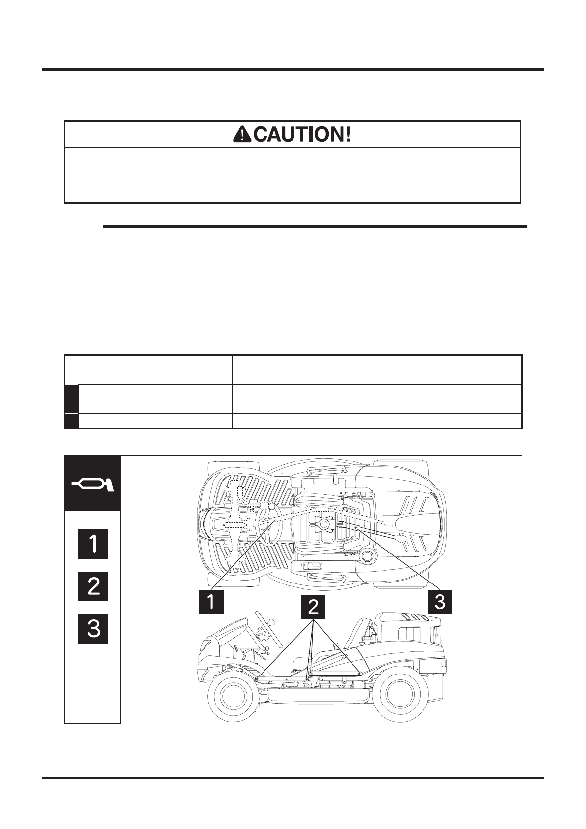
Greasing Points
• Grease regularly. Insufcient greasing may result in seizure or rusting, affecting
smooth operation of machine.
NOTE
• When using a manual grease pump, push handle five to six times. When handle
becomes heavy, stop pushing.
• When using a pneumatic grease pump, charge for two to three seconds.
• Set cutting rotary height to the lowest to grease link pivots.
Greasing Points (CMX 227 / CMX 186)
Location Schedule Grade
1 Propeller shaft Every 6 Months Chassis Grease
2 Cutting rotary link pivots Every 6 Months Chassis Grease
3 Cutting rotary drive shaft Every 6 Months Chassis Grease
5332M-0503-010E
-46-
Page 56
Maintenance 5
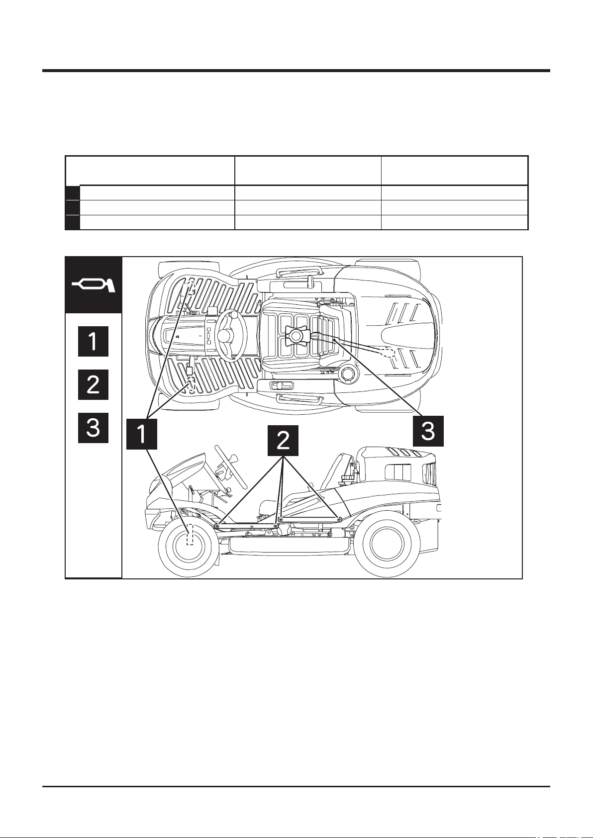
Greasing Points (CM 226 / CM 185)
Location Schedule Grade
1 Front knuckles Every 6 Months Chassis Grease
2 Cutting rotary link pivots Every 6 Months Chassis Grease
3 Cutting rotary drive shaft Every 6 Months Chassis Grease
5335M-0503-010E
-47-
Page 57
5
Maintenance
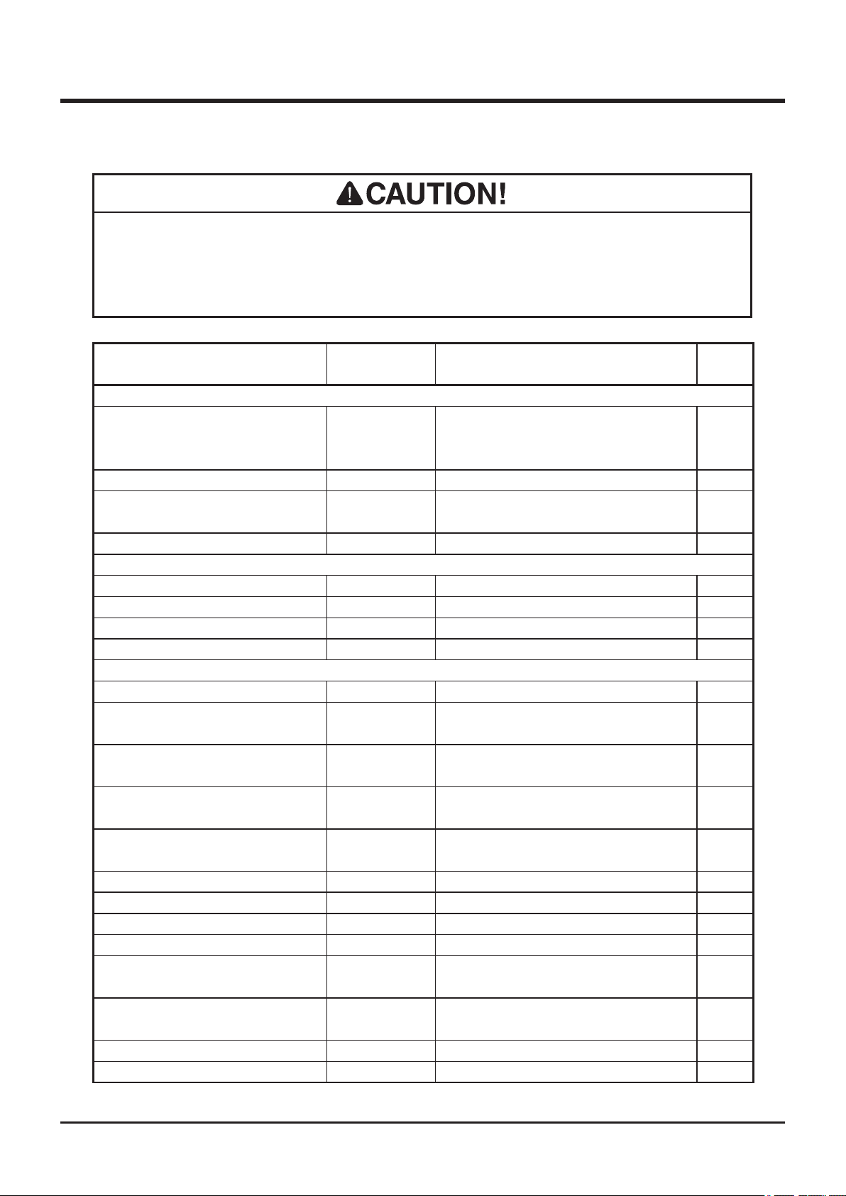
List of Consumables and Spares
• When replacing consumable or spare, always use CANYCOM genuine parts.
Using non-CANYCOM parts may reduce machine's performance or service life.
Note that it may also void warranty and certication for relevant standards.
Item Part No. Schedule Qty.
Engine
Initially 50 hrs.
Oil Filter Cartridge 248-65801-00
Air Cleaner Element 263-32610-A1
Spark Plug (NGK BPR5ES)
Wire (Throttle)
Fuel System
Hose (Carburator - Fuel Pump)
Hose (Fuel Pump - Fuel Filter)
Hose (Fuel Filter - Fuel Cock) 53320316000 Every 2 years. 1
Hose(Fuel Cock - Fuel Tank) 53320315000 Every 2 years. 1
Drive Train
V-belt (HST) 08521300036 Replace if defective. 1
Tire (Front)*1, *2 53322202000
Tire (Front)*3 53042204000
Tire (Rear)*1, *2 53322302000
Tire (Rear)*3 53042301100
Tire Tube (Front)*1, *2 53042205000 Replace if defective. 2
Tire Tube (Front)*3 53042205000 Replace if defective. 2
Tire Tube (Rear)*1, *2 53322303000 Replace if defective. 2
Tire Tube (Rear)*3 42012543000 Replace if defective. 2
Brake Lining (Rear) 73019901000
Brake Lining (Front) 73069901000
Wire (Rear Brake) 53323305000 Replace if defective. 1
Wire (Front Brake) 53323306000 Replace if defective. 1
065-01402-80
53320101100 Replace if defective. 1
263-68006-B3 Every 2 years. 1
263-68007-B3 Every 2 years. 1
After - Every 200 hrs.
Replace if defective.
Every 200 hrs or seasonally.
Clean: every 50 hrs.
Replace if defective.
Replace if defective
or reaches the wear limit.
Replace if defective
or reaches the wear limit.
Replace if defective
or reaches the wear limit.
Replace if defective
or reaches the wear limit.
Replace if defective.
(Replace in pairs)
Replace if defective.
(Replace in pairs)
1
1
2
2
2
2
2
2
2
*1: CMX227, *2: CM 226, *3: CMX186, CM185
-48-
Page 58
Maintenance 5
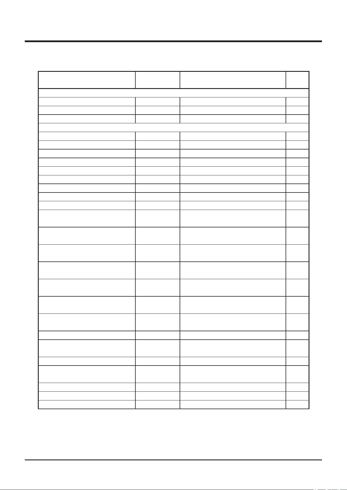
Item Part No. Schedule Qty.
Drive Train
Wire (Differential Lock) 53323402000 Replace if defective. 1
Wire (AWD)*1 53323452000 Replace if defective. 1
Cooling Fan 53352023000 Replace if defective. 1
Cutting System
Blade Set (Iai) Z3324202010 Replace if defective. 1
Rubber Plate (Front Skirt, Center)*1 53322114000 Replace if defective. 1
Rubber Plate (Front Skirt, Center)*2 53332109000 Replace if defective. 1
Rubber Plate (Front Skirt, Center)*3 53382114000 Replace if defective. 1
Rubber Plate (Front Skirt, Center)*4 53342109000 Replace if defective. 1
Rubber Plate (Front Skirt, Sides)*1 53322113000 Replace if defective. 2
Rubber Plate (Front Skirt, Sides)*2 53332108000 Replace if defective. 2
Rubber Plate (Front Skirt, Sides)*3 53382113000 Replace if defective. 2
Rubber Plate (Front Skirt, Sides)*4 53342108000 Replace if defective. 2
Rubber Plate (Front Diff.-Blade
Shield)*1,*3
Rubber Plate (Front Diff.-Blade
Shield)*2, *4
Rubber Plate (Front Axle, Rear
Right)*1
Rubber Plate (Front Axle, Rear
Right)
*2, *4
Rubber Plate (Front Wheel,
Inside)*1, *3
Rubber Plate (Front Wheel, Inside)
*4
Rubber Plate (Front Wheel, Rear
Inside)
*2,
*4
Rubber Plate (Blade Shield, Rear) 53324113000 Replace if defective. 1
Rubber Plate (Blade Shield, Rear
Left)
V-Belt (Cutting Rotary)
53352111000 Replace if defective. 1
53362114000 Replace if defective. 1
53212118000 Replace if defective. 1
53332112000 Replace if defective. 1
53322116000 Replace if defective. 1
*2,
53062121000 Replace if defective. 1
53232132000 Replace if defective. 1
53324114000 Replace if defective. 1
08521600037 Replace if defective. 2
Brake Lining (Cutting Rotary)
Wire (Cutting Rotary Clutch)
Free Lock (Cutting Height Adjuster)
Cutting Blade Stay 53324201000 Replace if defective. 1
*1: CMX227, *2: CM 226, *3: CMX186, *4: CM185
53104301000 Replace if defective. 2
53322408000 Replace if defective. 1
53324068000 Replace if defective. 1
-49-
Page 59
5
Maintenance
Item Part No. Schedule Qty.
Electrical System
Battery 37053901000
Fuse, 30A (Green, Main)
Fuse 10A (Red, Lights) 09801001002
Light Bulb (Head Lamp) 53320203100
Light Bulb (Tail Lamp)
*1
09801003002
09808121502
Replace if defective.
Replace if defective.
Replace if defective.
Replace if defective.
Replace if defective.
Removing and Installing Body Panels
1
1
1
1
1
• Cut or pinch hazard exists when removing or installing body panels; beware of
sharp edges and pinch points.
• Make certain to reinstall panels after removing for repairs or inspection.
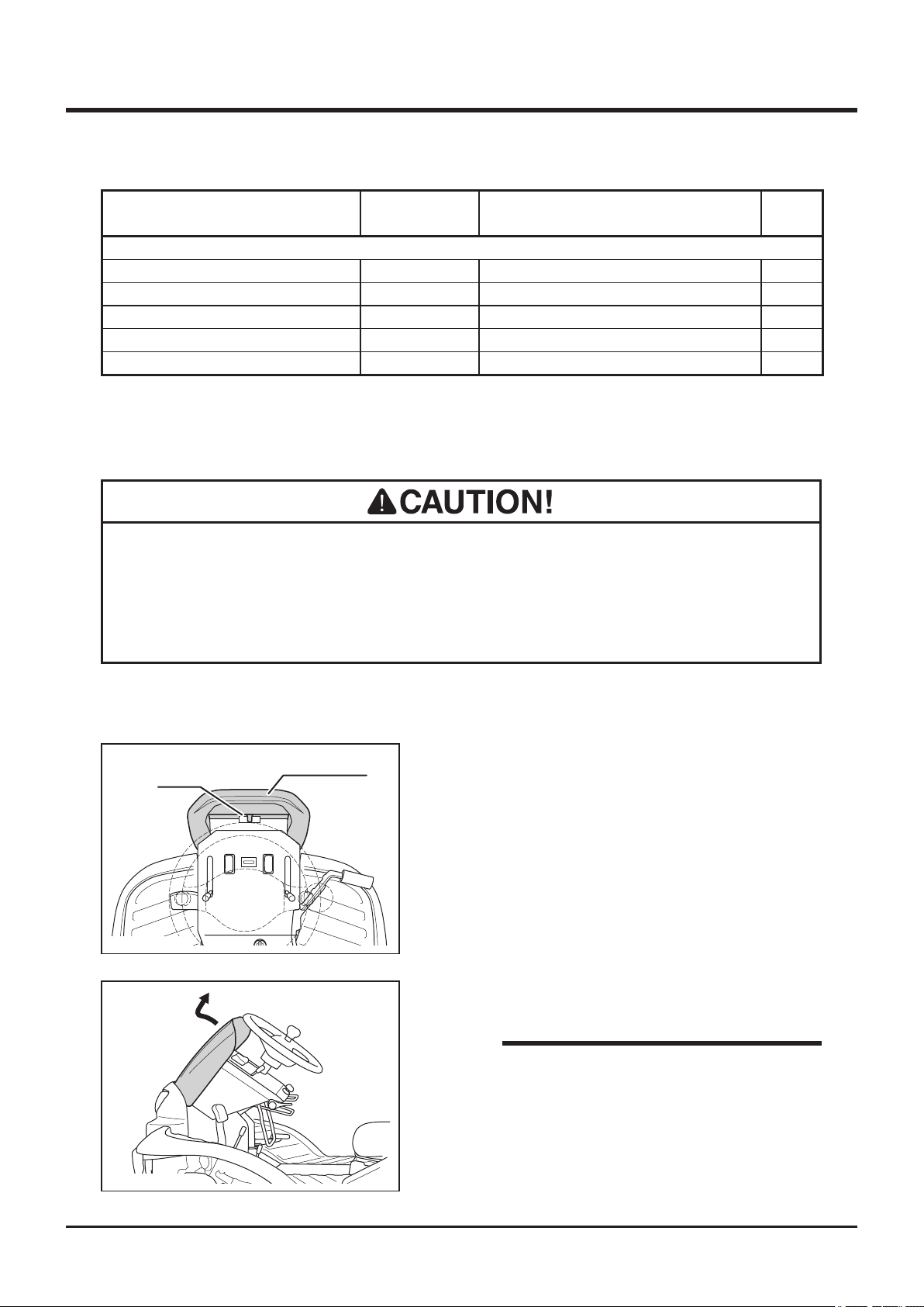
Front Cover
Latch
Front Cover
5332M-0401-040E
1. Pull top side of front cover to unlock latch.
2. Pull up front cover.
5332M-0401-110E
NOTE
• Tool box is provided under the front cover.
Use this tool box to store tools or substitute
cutting blades.
-50-
Page 60
Maintenance 5
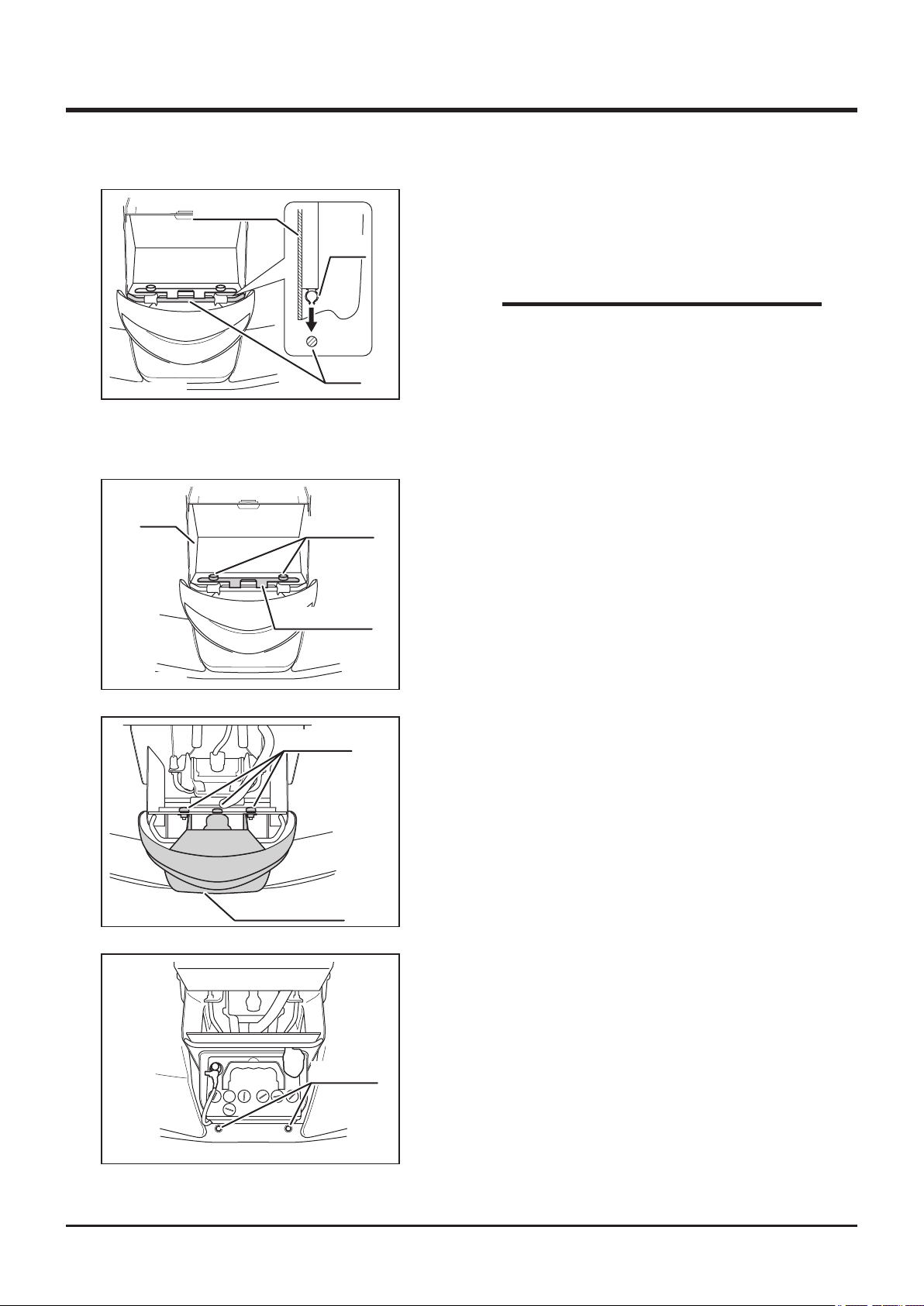
Front Cover
5332M-0401-140E
Head Lamp
Tray
Clip
Rod
Knob Bolt
Fixing Bracket
3. Raise steering wheel to the maximum angle
and t clip on the back of front cover to rods.
4. Fit upper part of front cover.
NOTE
• Beware not to catch front cover by the
plates on both sides when you installing
front cover.
1. Remove front cover.
2. Remove 2 knob bolts xing the tray.
3. Remove xing bracket and lift tray.
5332M-0509-030E
5332M-0509-040E
Knob Bolt
4. Remove 3 knob bolts xing head lamp unit to
remove head lamp unit.
Head Lamp Unit
5. Insert projections at the bottom of head lamp
unit into holes of grommet on bumper and
install adversely.
Grommet
5332M-0509-060E
-51-
Page 61
5
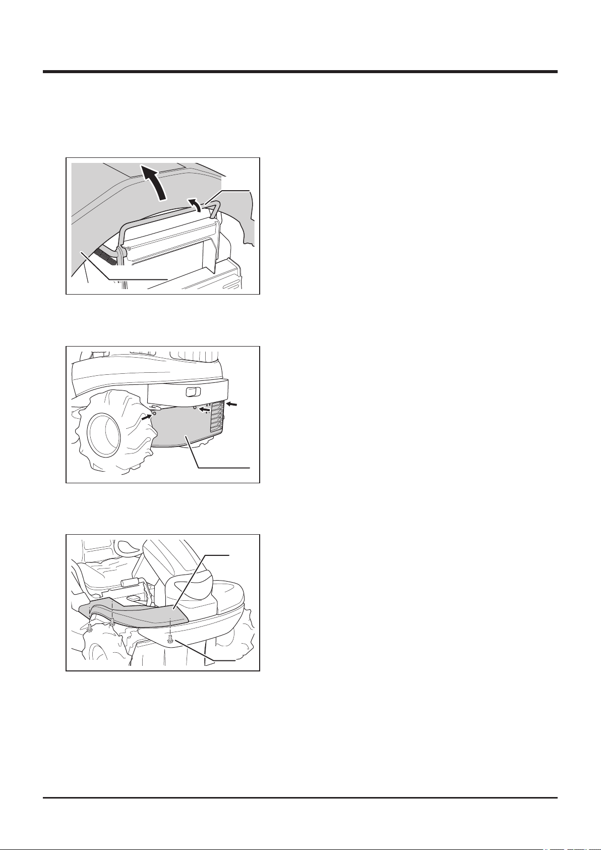
Engine Hood
Engine Hood
5332M-0505-030E
Lower Rear Cover
Maintenance
1. Pull lever and open engine hood.
Lever
5332M-0505-040E
Step
Rear Cover
Step
1. Remove 4 bolts.
2. Remove lower rear cover.
1. Remove 3 bolts xing step.
2. Remove step.
3. Remove step on the other side in the same
way.
5332M-0505-080E
Bolt
-52-
Page 62
Maintenance 5
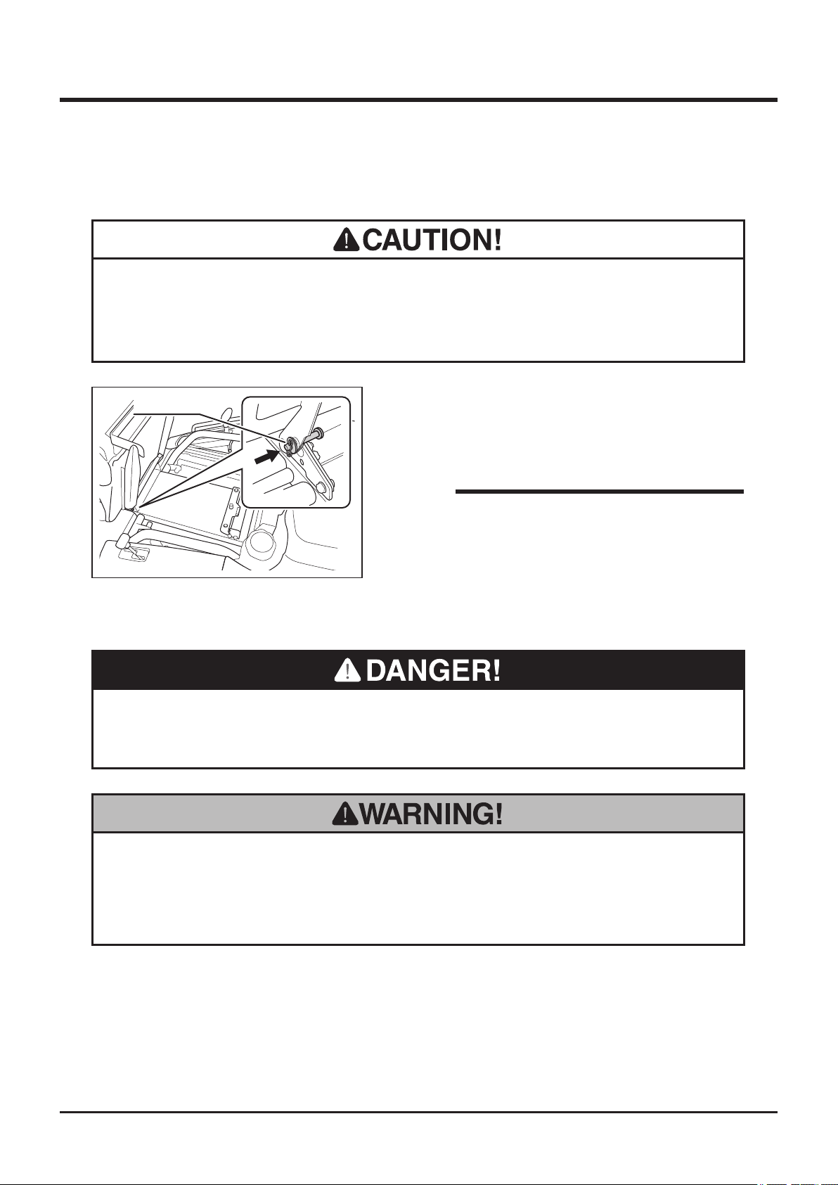
Seat Bracket
• Always slide seat to the rear-most position when lifting seat. If seat is not in the
rear-most position, slide lever may interfere with step, preventing seat to be
lifted to the holding position.
Safety Pin
1. Slide seat to the rear-most position.
2. Lift seat and push safety pin toward inside to
hold seat.
NOTE
• Move seat and check if the seat is held in
place rmly.
5332M-0401-080E
Cutting Blade Shield
• Stop engine before opening cutting blade shield. Opening shield when cutting
blade is moving may result in injury or death.
• Make sure cutting blade shield is securely locked in the lowest position and
does not open to the side. Loose shield may allow objects to be thrown,
resulting in injury to the operator or by-standers or in property damage.
-53-
Page 63
5
Maintenance
Lock Lever
Cutting Blade Shield
5335M-0505-070E
5335M-0505-090E
A
B
Lock Lever
Lock Pin
Lock Positions
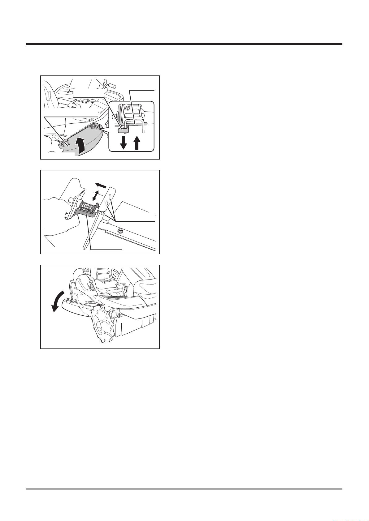
Flipping up shield
1. Push lock pin to unlock shield.
2. Pull up lock lever and move shield up or
down to one of three positions.
3. Press down lock lever to lock shield. Lock pin
will also return to lock position automatically.
Opening shield to the side
1. Squeeze lock lever as shown (A).
2. Keep lock lever squeezed and move shield
to one of three lock positions (B).
3. Release lock lever at the selected lock
pos ition so that the pi n o n l ock lever
positively ts into the hole at lock position.
5335M-0505-080E
-54-
Page 64
Engine
• Always stop engine and remove ignition key before servicing.
• An engine that has been running is very hot. Allow engine to cool before
servicing, or severe burns may result.
• Keep re and spark away when servicing.
Engine Oil
Maintenance 5
• Make certain to fill engine with correct grade of oil to the specified level.
Insufcient amount or wrong grade of oil reduces performance and may cause
permanent damage to engine.
• Dispose of the drained oil properly.
NOTE
• To obtain correct reading, check oil level before starting, or wait about 10 minutes
after stopping engine to allow oil to drain back to oil pan.
• Always check oil level on a level surface.
• Oil to use and capacity: Page 45.
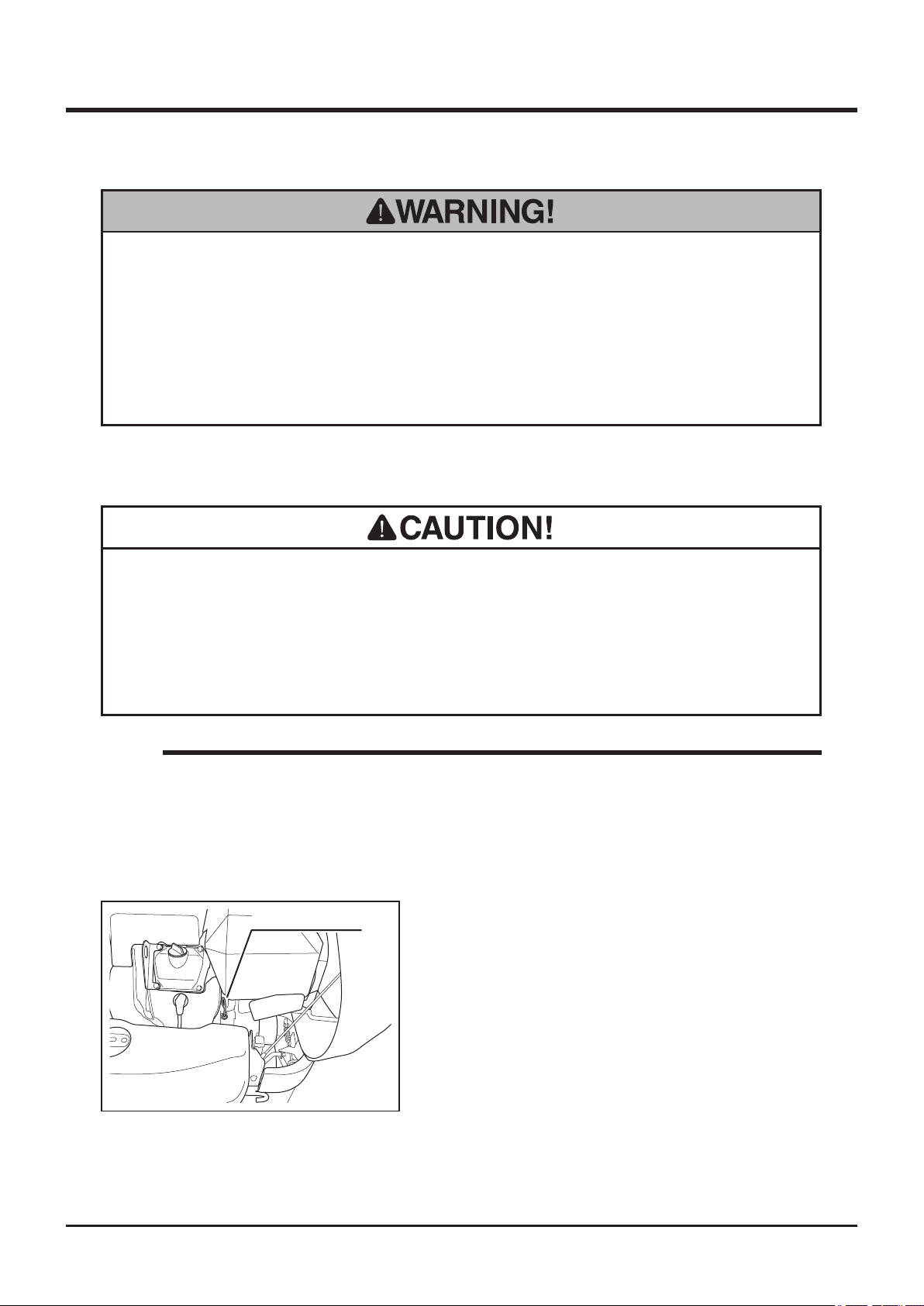
Oil Level Gauge
Inspecting
1. Park machine on a level surface.
2. Open engine hood.
3. Pull out dipstick and wipe it clean.
4. Insert dipstick fully and pull it out.
5332M-0506-010E
-55-
Page 65
5
Maintenance
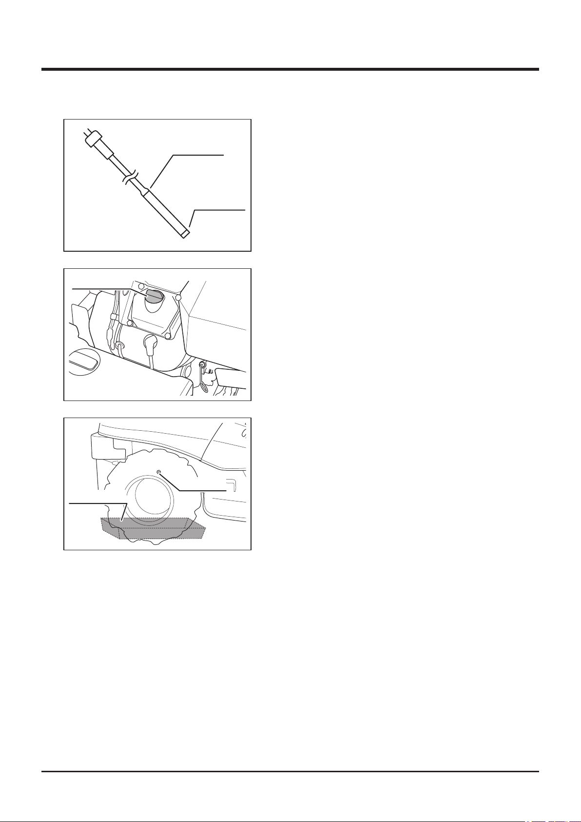
5. Visually inspect oil level. Make sure oil level
5321M-0506-020E
Oil Filler Cap
5332M-0506-030E
Upper Limit
Lower Limit
is between upper and lower limits. If it is
below lower limit, add oil.
6. Visually inspect condition of oil. If it is too
dirty or viscosity is not normal, change oil.
7. Put dipstick back in place.
8. Close engine hood.
Filling
1. Open engine hood.
2. Remove oil ller cap.
3. Fill specied amount of correct oil into ller.
4. Check oil level. Make sure oil level is
between upper and lower limits.
5. Put oil ller cap back in place.
6. Close engine hood.
Oil Drain Pan
5335M-0506-010E
Drain Plug
Changing
1. Have an appropriate oil drain pan.
2. Open engine hood.
3. Remove oil ller cap.
4. Remove drain plug to drain oil.
5. Put drain plug back in place.
6. Fill oil.
7. Check oil level and to make sure oil level is
appropriate.
8. Put oil ller cap back in place.
9. Close engine hood.
-56-
Page 66
Oil Filter Cartridge
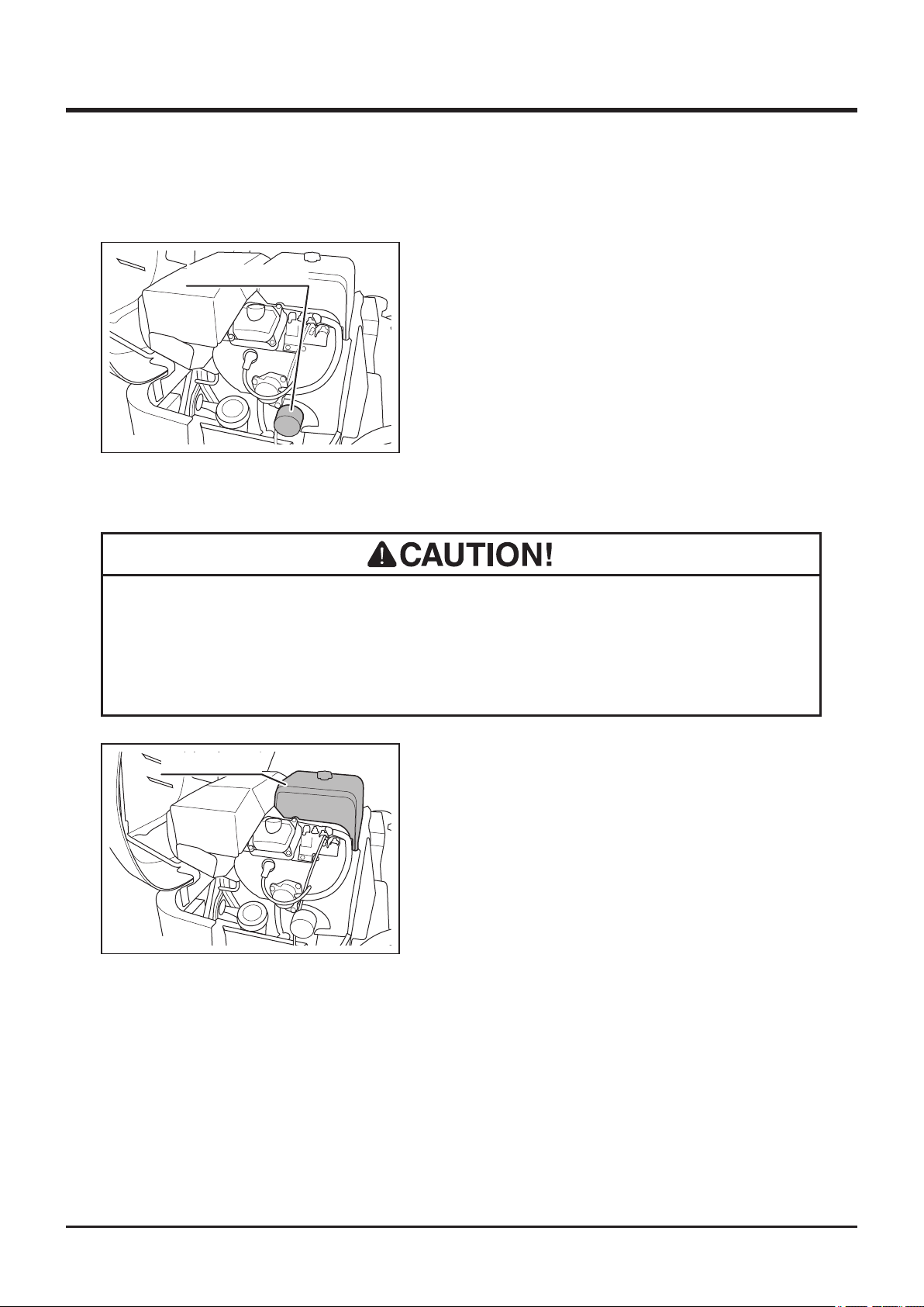
Oil Filter Cartridge
5332M-0506-050E
Air Cleaner
Maintenance 5
1. Open engine hood.
2. Follow the instructions in Operator's Manual
for the engine to change oil lter cartridge.
3. Close engine hood.
• Clean air cleaner element daily. Dirty air cleaner element causes poor starting,
reduces engine performance and shortens engine life.
• Replace air cleaner element if damaged.
Air Cleaner Lid
5332M-0506-060E
1. Open engine hood.
2. Follow the instructions in Operator's Manual
for the engine to inspect, clean or change
air cleaner element.
3. Close engine hood.
-57-
Page 67
5
Maintenance
Spark Plugs
• Never pull ignition cable when removing a spark plug cap. Conductor in the
cable may be severed or damaged.
• If a spark plug is damaged, replace it with a new one.
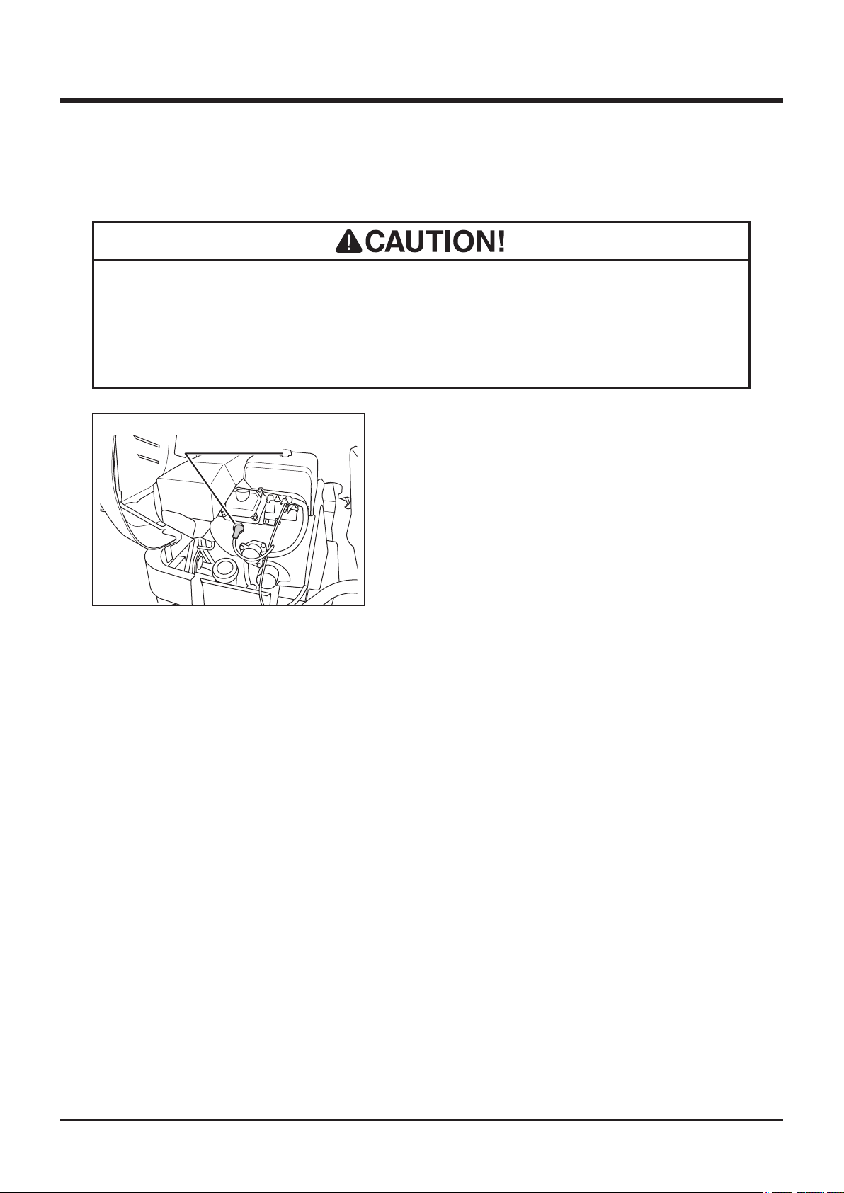
Spark Plug Cap
(On both sides)
1. Open engine hood.
2. Follow the instructions in Operator's Manual
for the engine to inspect, clean, or change
spark plugs.
3. Close engine hood.
-58-
Page 68
Drive Train
• Stop engine and remove ignition key when servicing drive train.
• Allow machine to cool off before servicing. Engine and its ancillaries are very
hot after operation and may pose a burn hazard.
• Dispose of drained oil properly.
Maintenance 5
Tires
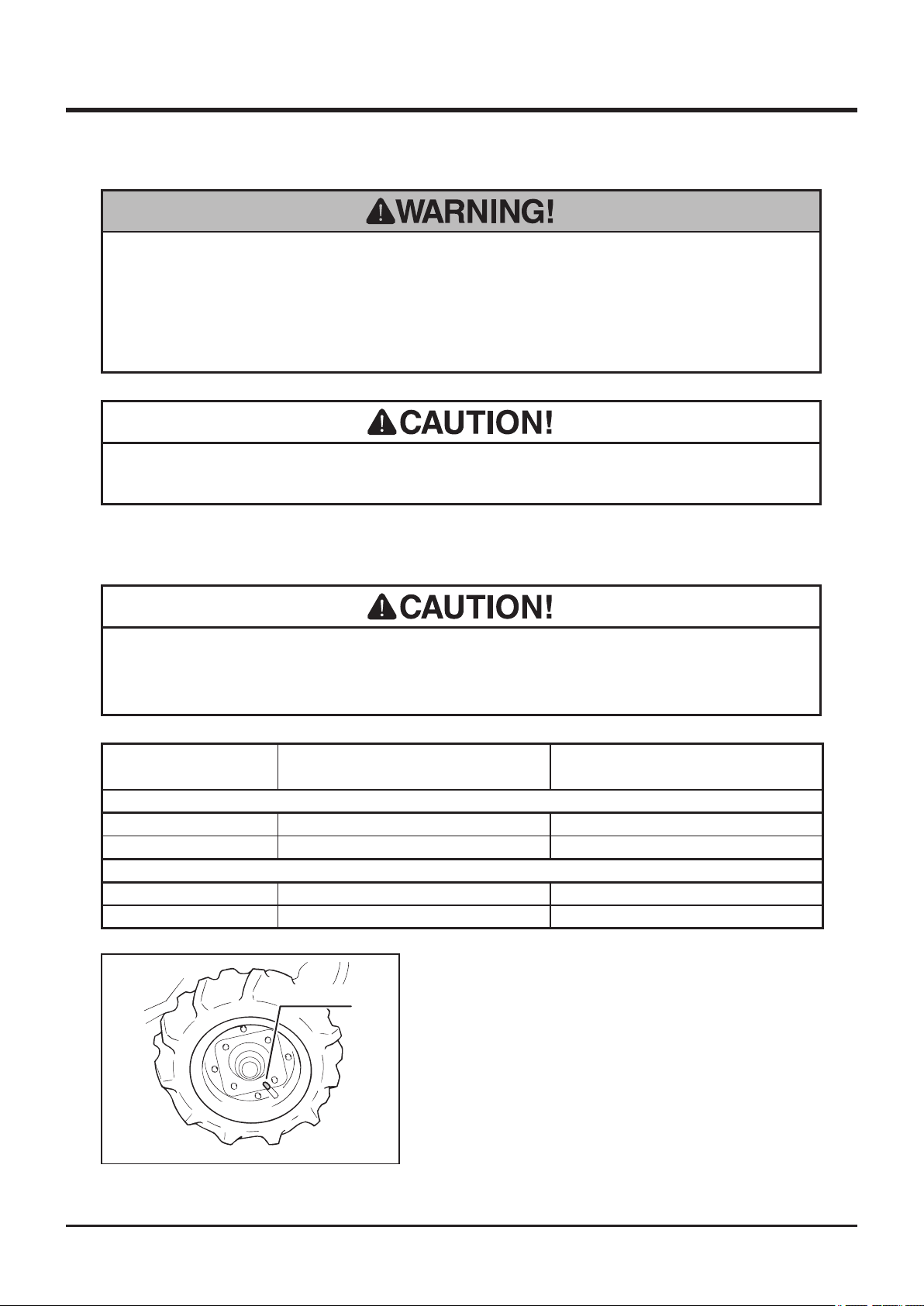
• Inate tires to the specied pressure. Under- or over-ination causes uneven
wear or other damages to tires.
Tire Size Pressure KPa(kgf/cm2)
CMX227 / CM226
Front Wheel AGR 4.00-7 (2PR) 120 (1.2)
Rear Wheel 17×8.00-8 (4PR) 240 (2.4)
CMX186 / CM185
Front Wheel AGR 3.50-7 (2PR) 110 (1.1)
Rear Wheel 16×7.00-8 (2PR) 110 (1.1)
1. Park machine on a level ground.
Valve Cap
2. Remove valve cap.
3. Check tire air pressure. If different from the
5332M-0507-010E
specied values, adjust pressure.
4. Put valve cap back in place.
-59-
Page 69
5
Transmission Oil
NOTE
• Oil to use and capacity: Page 45.
Maintenance
1. Park machine on a level ground.
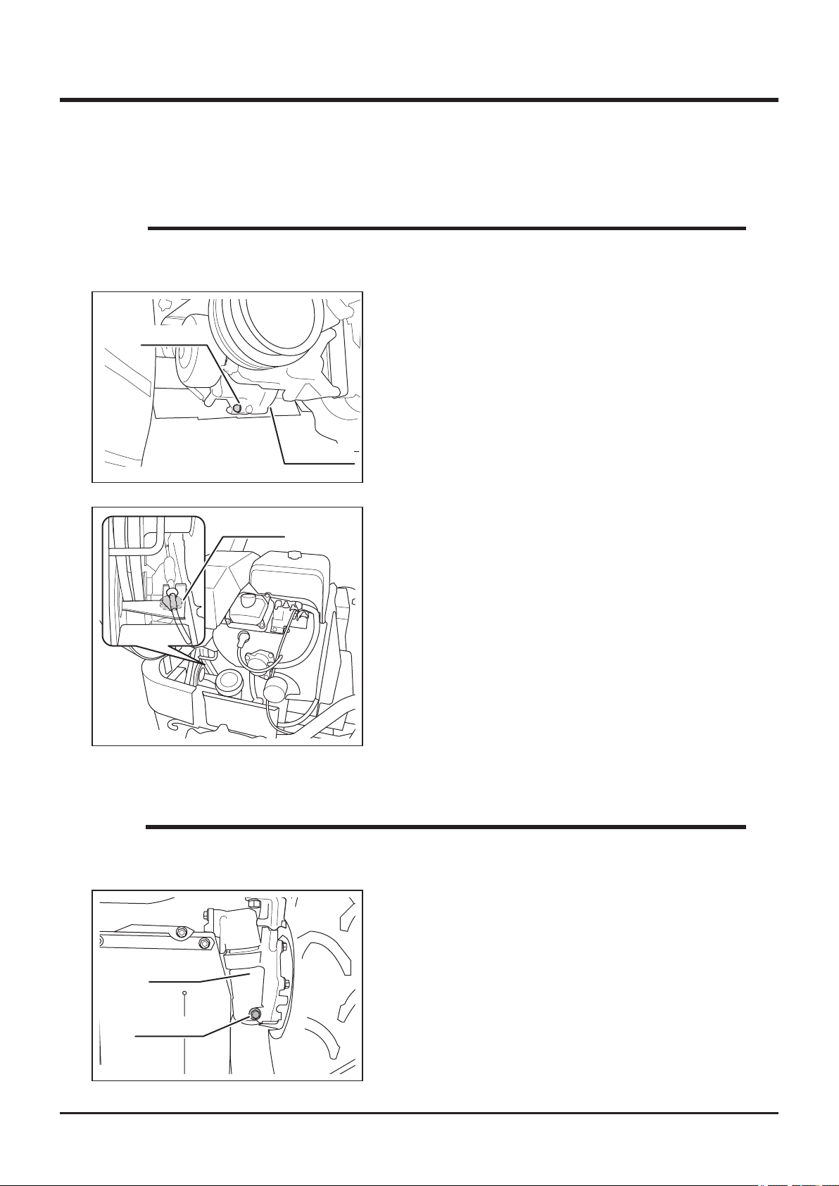
Drain Plug
5332M-0507-040E
Filler Cap
2. Have an appropriate oil drain pan.
3. Remove transmission oil drain plug to drain
oil.
4. Install drain plug back in place.
Check Bolt
5. Open engine hood.
6. Remove transmission oil ller cap.
7. Remove check bolt.
8. Fill specied amount of correct oil into ller,
up to check bolt hole.
9. Put check bolt back in place.
10. Put ller plug back in place.
11. Close engine hood.
5332M-0507-020E
Front Axle Oil (CMX227 / CMX186)
NOTE
• Oil to use and capacity: Page 45.
1. Park machine on a level ground.
2. Have an appropriate oil drain pan.
3. Remove drain plug on the left front knuckle
Knuckle
4. Remove drain plug on the right front knucle
Drain Plug
5332M-0507-100E
-60-
to drain oil.
to drain oil as well.
Page 70
Maintenance 5
NOTE
• Drain plug for the right front knucle is on
the back side of the front axle.
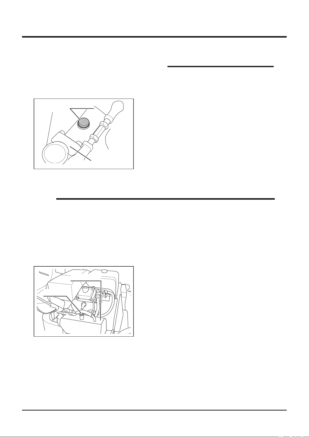
Filler Plug
5. Install both drain plugs back in place.
6. Remove right front step.
7. Remove oil ller cap.
8. Fill specied amount of oil into ller.
9. Install ller plug back in place.
10. Install right front step.
Front Wheel
Axle (Right)
5332M-0507-090E
HST (Hydrostatic Transmission) Fluid
NOTE
• To obtain correct reading, check HST uid level before starting, or wait until HST
uid cools off sufciently. Hot HST uid expands in volume and does not provide
correct reading.
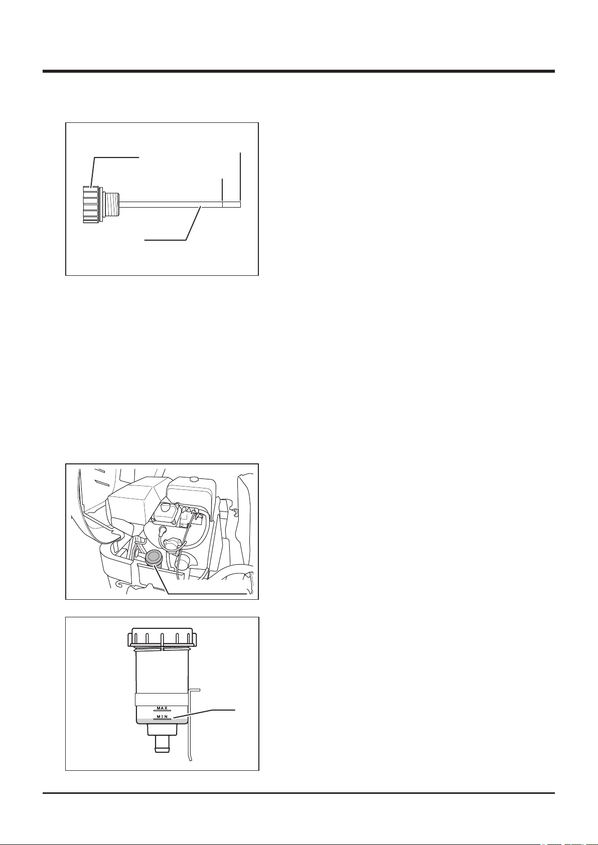
• When oil is sufficiently cooled and is at the [MIN] level, its amount is sufficient.
• Do not exceed beyond [MAX] level. HST fluid may espand and overflow.
• Oil to use and capacity: Page 45.
Filler Cap
5335M-0507-010E
HST Oil Tank
Inspecting - Models with charge-pump
1. Park machine on the level ground.
2. Open engine hood.
3. Unscrew and remove ller cap.
-61-
Page 71
5
Filler Cap
Lower Limit
Upper Limit
Maintenance
4. Wipe dip stick with clean cloth. Reinstall ller
cap and screw it fully.
5. Unscrew and remove ller cap again. Visually
inspect that oil level is between the upper
and lower limits on dip stick. If it is below the
lower limit, ll oil.
5335M-0507-020E
Dip Stick
6. Reinstall ller cap and screw it fully.
7. Close engine hood.
Filling - Models with charge-pump
1. Open engine hood.
2. Remove ller cap.
3. Fill specified HST fluid into filler so that oil
level is between upper and lower limits on
dipstick.
4. Reinstall ller cap back in place and screw it
securely.
5. Close engine hood.
Inspecting - Models without charge-pump
1. Park machine on the level ground.
2. Open engine hood.
3. Visually inspect that oil level is between [MIN]
5335M-0507-030E
5335M-0507-050E
HST Oil Reservoir
MIN
and [MAX] lines on oil reservoir. If it is below
[MIN], ll oil.
4. Close engine hood.
Filling - Models without charge-pump
1. Open engine hood.
2. Remove cap on HST oil reservoir.
3. Fill specied HST uid into reservoir so that
oil level is above [MIN] line on reservoir.
4. Reinstall cap back in place and screw it
securely.
5. Close engine hood.
-62-
Page 72
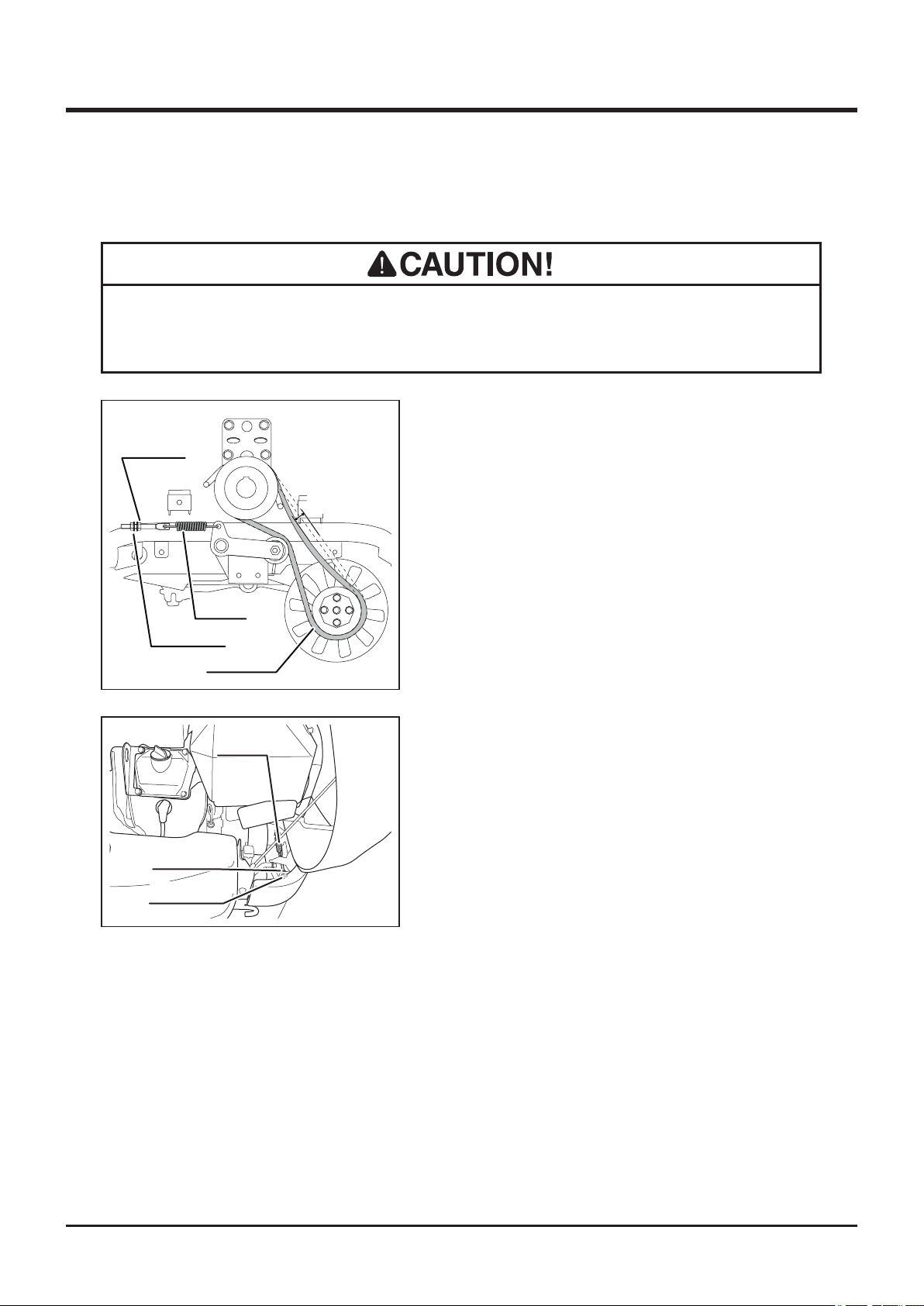
Maintenance 5
Drive Belt
• Adjust belt tension properly. Inproperly tensioned belt may reduce performance
and its service life.
1. Open engine hood.
Lock Nut
Adjust Nut
5332M-0507-080E
Lock Nut
2. Check V-belt tension. Push V- belt by nger
and check that deection at center point A is
in the range of 10 to 20 mm. If it is out of this
A
range, adjust with adjust nut.
3. Visually inspect belt. Replace belt if it is
damaged. For replacement, contact your
CANYCOM representative.
Spring
4. Close engine hood.
Drive Belt
Spring
Adjust Nut
5332M-0507-110E
-63-
Page 73
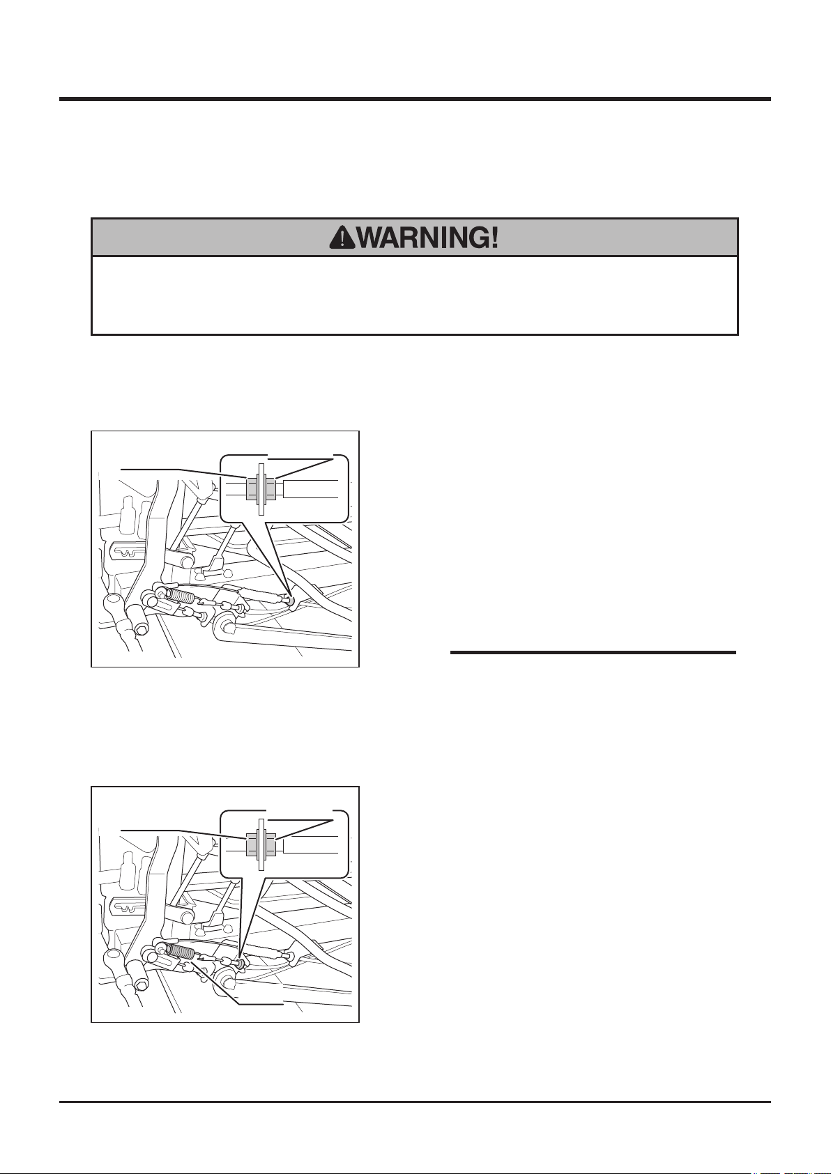
5
Maintenance
Parking Brake
• Always keep brake adjusted for maximum performance. Improperly adjusted
brakes may result in property damage, serious injury, or death.
1. Park machine on level ground.
2. Remove left step.
Lock Nut
5332M-0507-070E
Lock Nut
Adjust Nut
Adjust Nut
Rear Brake
3. Loosen lock nut
4. Adjust with adjust nut when brak peddal is
free so that the brake does not drag.
5. Adjust brake so that the brake works and the
brake pedal locks securely when brake pedal
is locked
6. Tighten lock nut.
NOTE
• If brake does not work even the brake pedal
is locked, the brake shoe is worn out. Please
contact your CANYCOM representative for
replacement.
Front Brake (CMX227/CMX186)
7. Lock brake pedal and Inspect that the strech
of spring is between 5mm and 8mm. If it is
5332M-0507-060E
not within this range, adjust it with adjust nut.
8. Tighten lock nut after adjustment
9. Install left step back in place.
Spring
-64-
Page 74
Cutting System
• Stop engine and remove ignition key when servicing.
• Allow machine to cool off before servicing. Engine and its ancillaries are very
hot after operation and may pose a burn hazard.
Cutting Blades
• When a blade is damaged, replace it and the other blade immediately. Always
Maintenance 5
replace blades in pair. Damage due to vibration may occur.
• When replacing blades, always replace both blades. Replace blade pins and
wave washers also.
• When a foreign object is tangled with the blade, immediately stop the engine
and remove the foreign object. Damage due to vibration may occur.
• When replacing blades, inspect blade stay. If stay is worn beyond wear
limit, damaged or deformed, replace it immediately. Contact your CANYCOM
representative.
• Blades and blade stay can become sharp due to wear. When handling blade or
blade stay, always wear thick gloves and handle carefully. Injury may occur.
• When replacing a blade, do not force it to remove. Blade can move suddenly,
causing injury. When it is difcult to remove, clean blade and remove foreign
object. Turn blade back and forth to remove.
-65-
Page 75
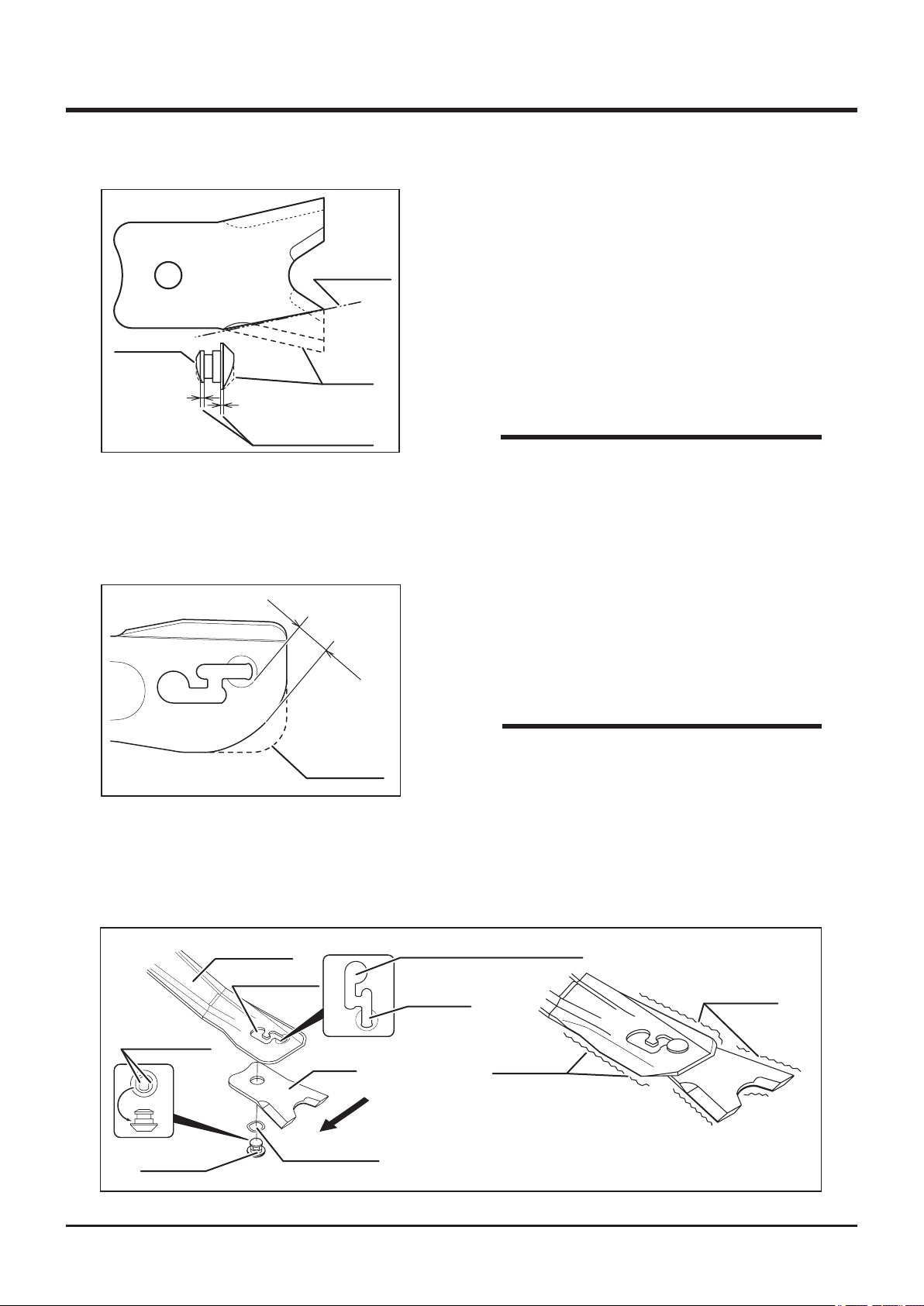
5
Maintenance
Inspecting
1. Open cutting blade shield.
2. Visually inspect blades and pin for wear
Wear Limit
and damage. If blades are worn normaly,
turn them over and use. Replace if both
Blade Pin
5331M-0508-010E
5332M-0508-040E
New
Replace when either
of the part wears out
15mm
When New
edges are worn. If blades or pin are worn
excessively, deformed, damged, or missing,
replace them with new components.
NOTE
• Wear Limit
Blade: Up to line connecting outer edge and
inner edge.
Blade Pin: Up to either of the shoulder.
3. Inspect cutting rotor stay. If stay is worn
excessively, deformed or damged, replace
with a new component.
4. Close blade sheild.
NOTE
• Wear Limit: U p to the solid lin e in the
left figure (should have more than 15mm
clearance between edge of rotor stay and
Flat Surfaces
Blade Pin
5332M-0508-020E
Rotor Stay
Mounting Slot
Blade
Rotating Direction
Wave Washer
mounting slot.)
• Contact your CANYCOM representative for
replacement of rotor stay.
Mounting, Dismounting Hole
Lug Hole
Wear Area
Handle with care.
These parts may become sharp
Wear Area
-66-
Page 76
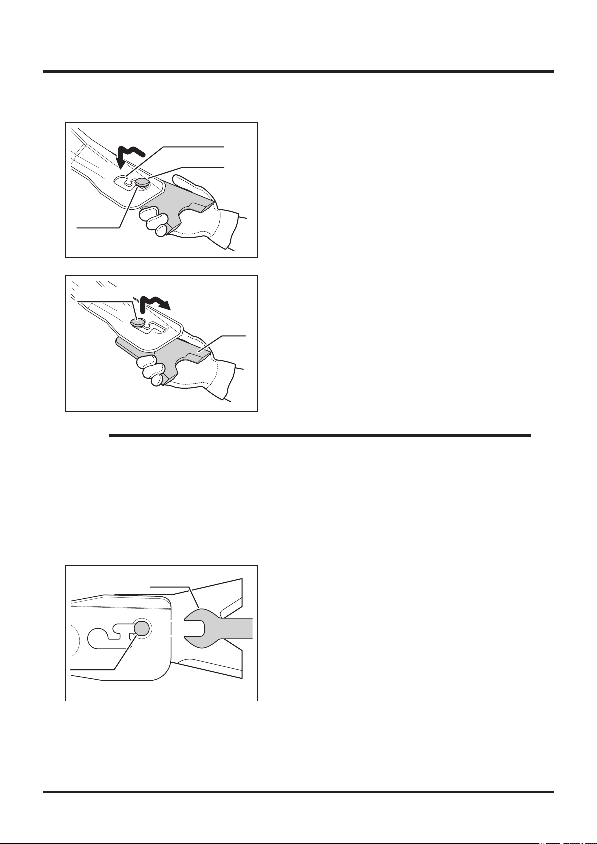
Flat Face
5332M-0508-050E
Mounting Pin
Mounting Slot
Flat Face
Maintenance 5
Replacing
1. Open cutting blade shield.
2. Noting the direction of the flat faces on
mounting pin, shift blade along mounting slot
to remove blade.
3. Install new mounting pin and wave washer
to blade and shift blade along mounting slot,
noting the direction of the at faces.
Blade
5332M-0508-060E
NOTE
• Always put thick gloves on and be cautious when handling blade because both
edges of rotor stay can get sharp by wear.
• Wear Limit: See page 66
• If dirt or grass enters into mounting slot, making removal of blade difcult, remove
dirt or grass with a screw driver before removing blade.
• If it is difcult to remove blade, use 24mm spanner to remove
Spanner
24
Blade Pin
5332M-0508-070E
-67-
Page 77
5
Maintenance
Cutting Rotary Drive Belt and Cutting Rotary Brake
• Never place any part of body under cutting blade shield when cutting blade is
rotating.
• Do not allow bystanders to come near machine when inspecting cutting rotary
brake.
• Ride on machine when testing cutting rotary brake.
• Never attempt to check the performance of cutting rotary brake with cutting
blade shield open. Stones or rocks can be thrown and cause damage to
surrounding properties or persons.
• Inspect cutting rotary brake whenever the performance of it seems inadequate.
• Adjust belt tension properly. Inproperly tensioned belt may reduce performance
and its service life.
• Always adjust cutting rotary brake after adjusting cutting rotary drive belt.
NOTE
• The V-belt stretches (breaks in) when it is new. Inspect and adjust the V-belt after
the rst day's (4 hours') use.
• For a longer service life, inspect and adjust (as necessary) the V-belt as the daily
pre-start up checks.
-68-
Page 78
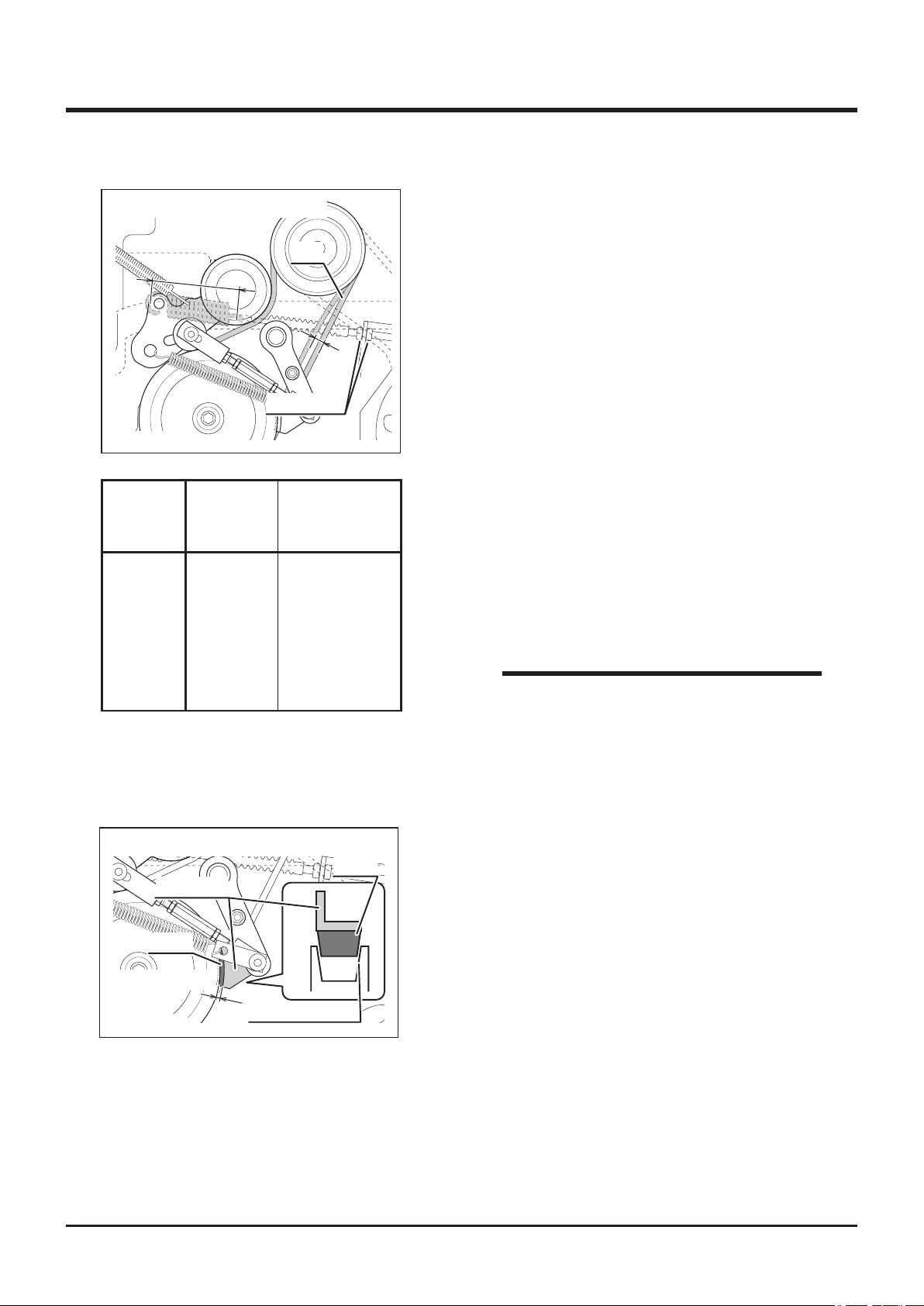
Maintenance 5
Cutting Rotary Clutch Lever: [ON]
B
Adjust Nuts
5335M-0508-010E
Deection
A
(insidehooks)
CMX227
CM226
10-15mm 112-113mm
CMX186
Belt
A
SpringLength
B
Inspecting and Adjusting
1. Removeenginehood,lowerrearcoverand
rearbumper.
2. Turncuttingrotaryclutchleverto[ON].
3. Inspect thecondition of V-belttobefree
ofdamages or wear.Replace if damaged
o r w o r n . C o n t a c t y o u r C A N Y C O M
representativeforreplacement.
4. InspecttheV-belttension.Pushthemiddle
of V-belttosee if the amountofdeflection
(slack)Atobewithintherangespecifiedin
thetableontheleft.
5. Ifthetensionisnotcorrect(deectionisnot
withintherange),adjustitwithadjustnuts.
CM185
Cutting Rotary Clutch Lever: [ON]
Back Plate
Lining
Less than 5mm
5335M-0508-020E
Groove for Lining
Lining
NOTE
• If the V-belt's deection cannot be adjusted
within the specified r a n ge, i t needs to
be re pla c ed. Con tac t yo ur CAN YCO M
representative for replacement.
6. Makesurebrakeliningisnottouchinggroove
onpulleyforlining.Alsomakesurethegap
betweentheedgeofpulleyandlining back
platetobelessthan5mm.
-69-
Page 79
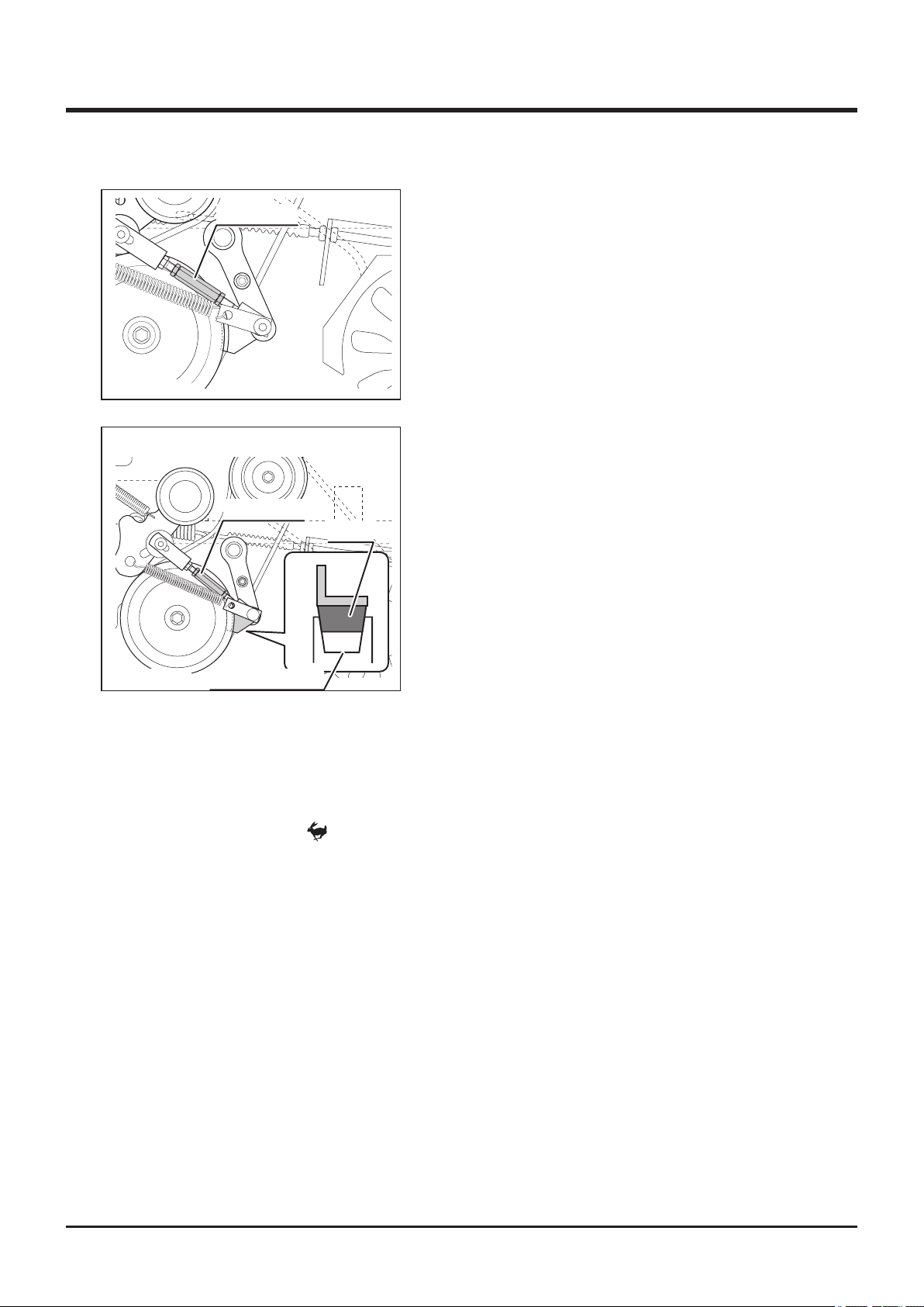
5
Maintenance
Turn Buckle
5335M-0508-030E
Cutting Rotary Clutch Lever: [OFF]
Turn Buckle
Lining
7. Adjust turn buckle if lining is touching groove
or back plate and the edge of pulley is more
than 5mm.
8. Turn cutting rotary clutch lever to [OFF].
9. Make sure lining is firmly in contact with
groove on pulley.
10. Jiggle turn buckle to make sure it has a little
play.
11. If lining is not rmly in contact with pulley or
turn buckle is too tight ti jiggle, re-adjust.
12. Turn cutting rotary clutch lever to [ON] and
[OFF] about 5 times and repeat the checks 4
5335M-0508-010E
Groove for Lining
and the following. Re-adjust if necessary.
13. Install engine hood, rear bumper, and lower
rear cover.
Inspecting the Blade Brake
1. Start engine.
2. Turn throttle lever to [ (fast)] to raise engine speed.
3.
Move cutting height adjust lever to [150] for CMX227 and CM226, or to [130] for CMX186
and CM185.
4. Move cutting rotary clutch lever to [ON] to rotate cutting blade.
5. Move cutting rotary clutch lever to [OFF] to observe if cutting blade stops. If it does not
stop (if it keeps turning by inertia), adjust cutting rotary brake. To see if cutting rotary
is running or not, observe the rotating sound of cutting blade, or open engine hood to
observe the rotation of cutting blade V-belt. Avoid observing cutting blade directly.
-70-
Page 80
Electrical System
• Always stop engine and remove ignition key when servicing electrical system.
• Shock hazard. Do not handle electrical components with wet hands.
Battery
• Never charge battery when the uid level is below "lower level" line. Charging
battery with insufcient uid may shorten battery life or cause an explosion.
Maintenance 5
• Battery fluid (diluted sulfic acid) is corrosive and causes severe burns. Be
extremeley cautious when handling battery fluid. If battery fluid is spilt on
clothes, immediately rinse with plenty of water. If spilt on skin or in an eye,
immediately rinse with plenty of water and promptly consult a physician.
• Explosion hazard. Keep open flame or spark away from battery. Hydrogen
gas generated during charging is extremely explosive.• Never ll battery uid
beyond "upper level" line. Battery uid may spill and cause damage to machine
or injury to person.
• Always disconnect (-) terminal rst, and connect (+) terminal rst. Disconnecting
or connecting in the opposite order may cause a short circuit.
• When installing battery, make certain to connect (+) and (-) terminals to their
original positions. Avoid contact between terminals and other surrounding
parts.
• Use wet cloth to clean battery. Dry cloth may generate static electricity, which
may cause explosion.
• Do not touch terminals. Electric shock may occur.
-71-
Page 81
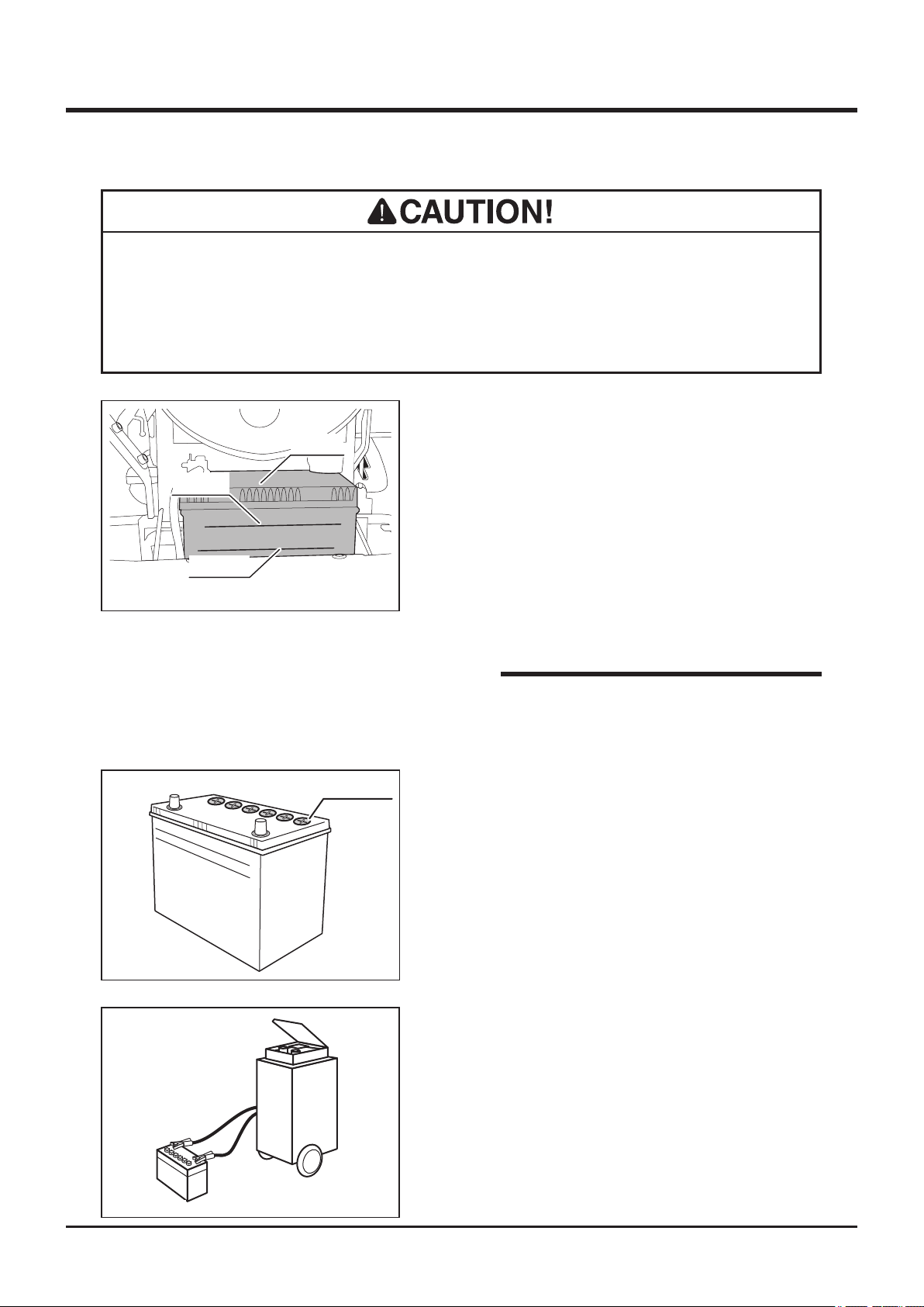
5
Maintenance
• Always remove battery from machine before charging. Failure to do so causes
damage to electrical components and wiring.
• Follow battery charger user's manual when charging.
Inspecting
Battery
UPPER
1. Park machine on level ground.
2. Remove front cover.
3. Visually inspect that battery fluid level is
between "UPPER" level and "LOWER" level
5332M-0509-010E
UPPER LEVEL
LOWER LEVEL
5321M-0510-020E
LOWER
Filler Cap
lines.
4. If uid level is near or below "LOWER" level
line, ll.
5. Install front cover back in place.
NOTE
• Instruction of removing head lamp and
battery is indicated back of the front cover.
Filling
1. Remove front cover.
2. Remove battery.
3. Remove ller cap.
4. Fill distilled water to "UPPER LEVEL" line.
5. Install ller cap.
6. Install battery.
7. Install front cover.
5116M-0509-040E
Charging
1. Remove front cover.
2. Remove battery from machine.
3. Follow instructions in battery charger user's
manual to charge battery.
4. When battery is fully charged, install battery
back in place.
5. Install front cover back in palce.
-72-
Page 82
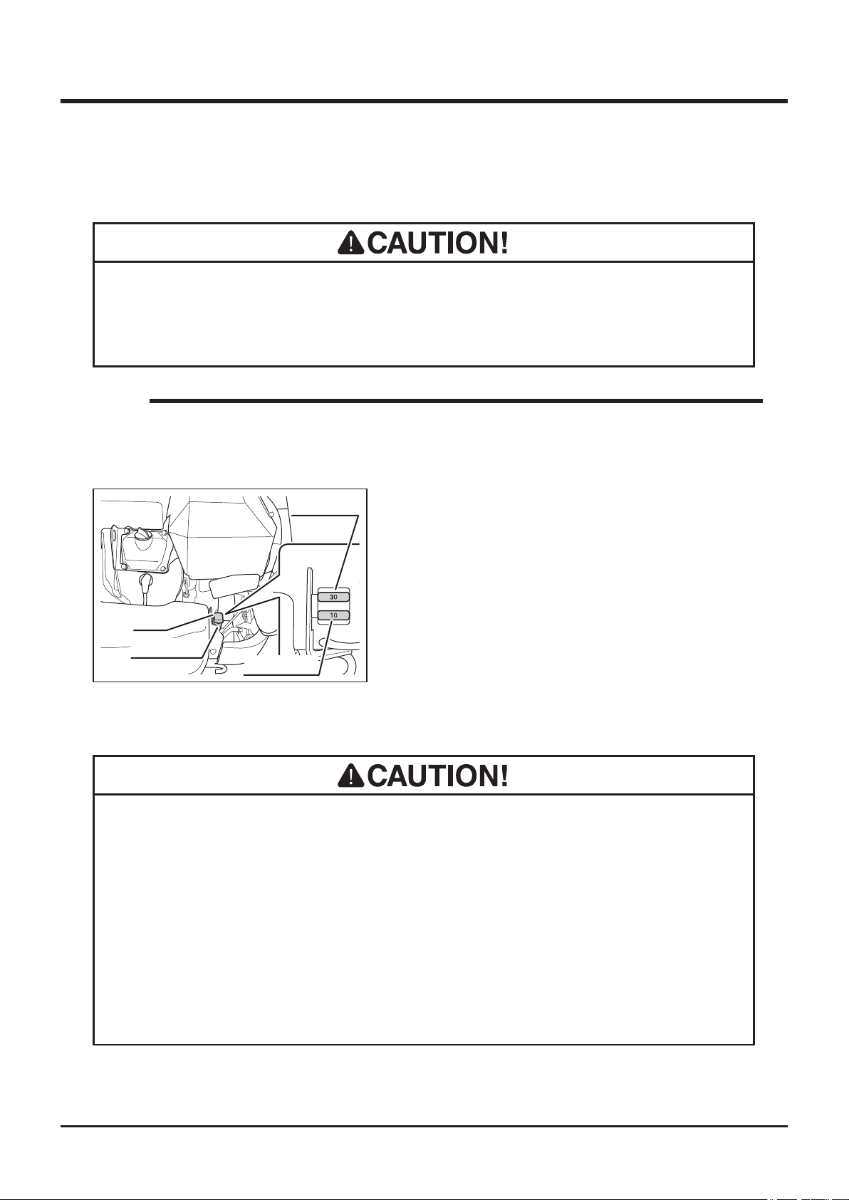
Maintenance 5
Fuses
• If a fuse blows, investigate the cause before replacing.
• Always replace a fuse with one of the correct rating.
NOTE
• Main Fuse: 30A. Lights Fuse: 10A
• Replacement Fuse: Page 49.
1. Open engine hood.
2. Open fuse case cap. Remove fuse and
visually inspect. If it is blown, replace it with
new one of the same rating.
3. Install fuse.
4. Install fuse case cap.
5. Close engine hood.
Cap
Fuse Case
5332M-0509-020E
Main Fuse
Lights Fuse
Light Bulbs
• When light bulb is burnt out, replace it with a new bulb.
• When replacing, always use a bulb of the correct rating. Wrong bulb may cause
malfunction or damge in electrical system.
• Do not touch bulb when it is hot. It may cause burns.
• Do not touch the glass part of light bulb directly with fingers. It may reduce
service life.
-73-
Page 83
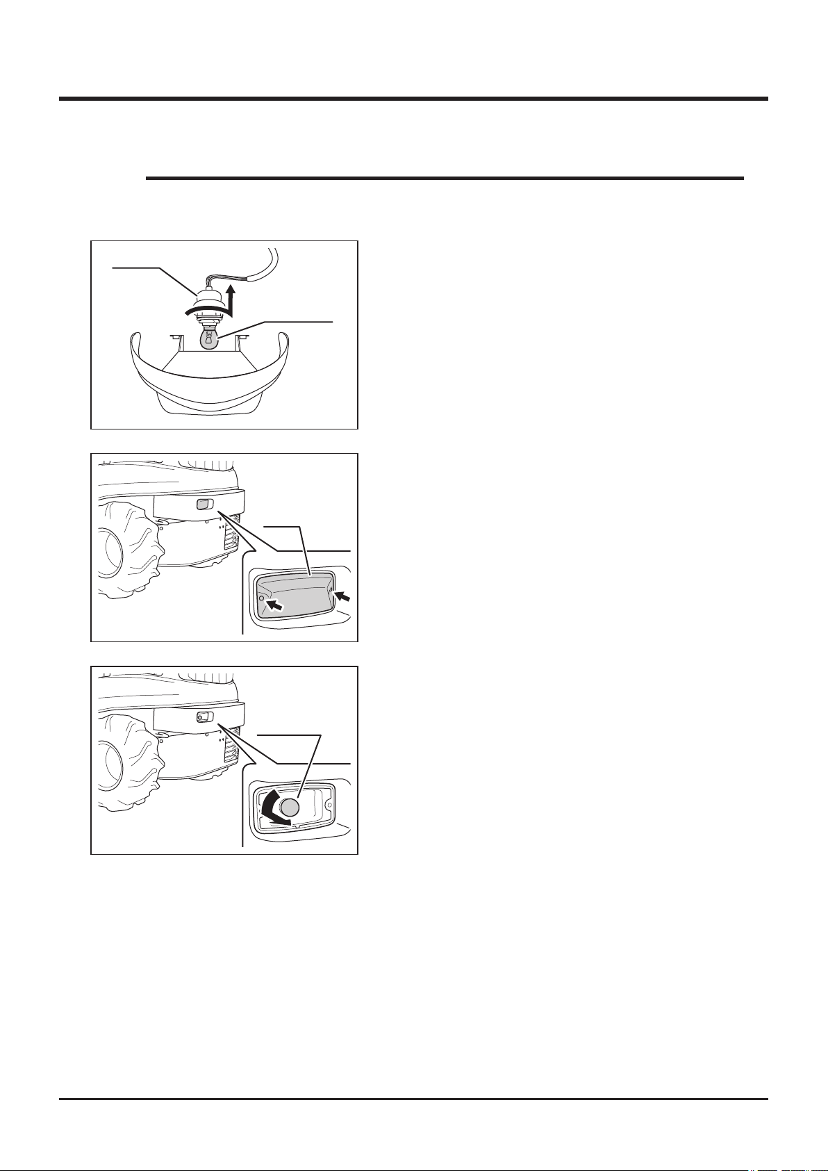
5
NOTE
• Light Bulbs to use: Page 48.
Maintenance
Socket
5332M-0508-050E
5332M-0509-070E
Light Bulb
Lens
Head Lamp
1. Remove front cover and head lamp unit.
2. Turn socket to remove.
3. Replace with new light bulb.
4. Install socket.
5. Install head lamp and front cover.
Rear Lamp (CMX227)
1. Remove 2 screws and remove lens.
5332M-0509-080E
2. Replace with a new light bulb.
3. Install lens back in place.
Light Bulb
-74-
Page 84
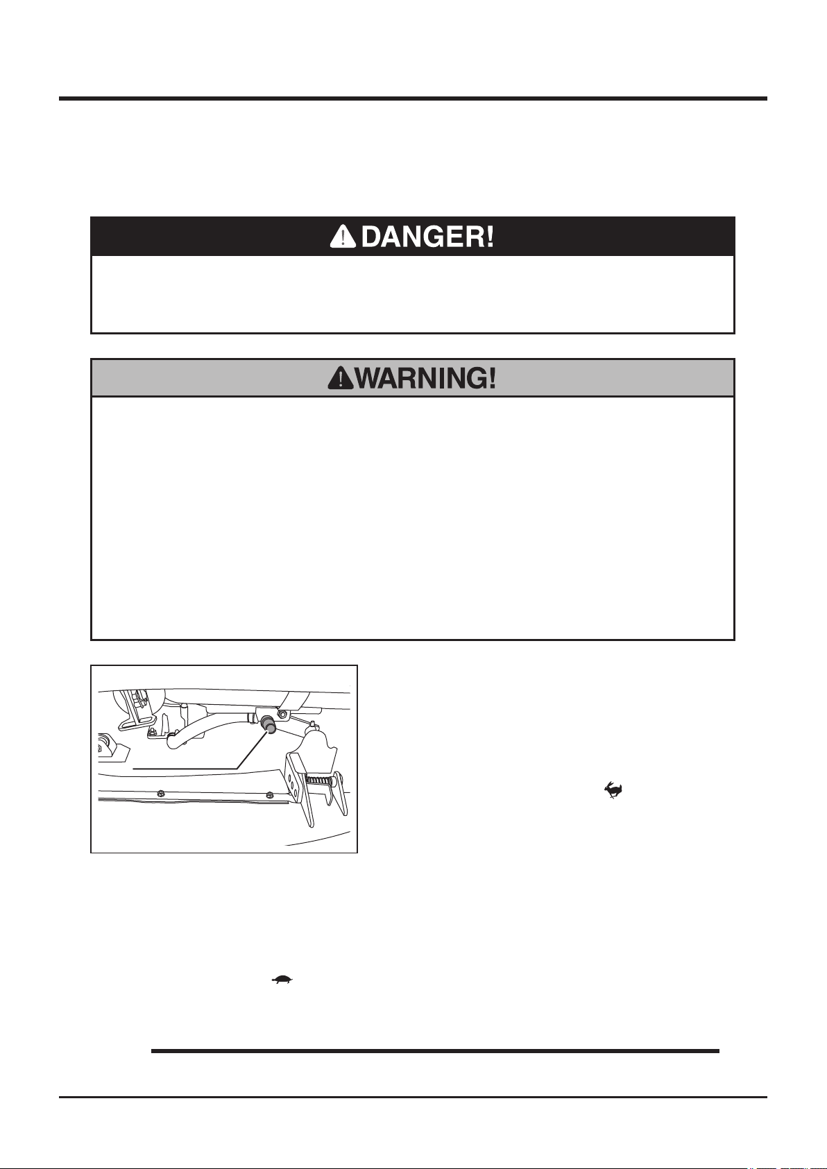
After Use Care
Cutting System
• Never place any part of body under cutting blade shield when cutting blade is
rotating.
• Do not allow bystanders to come near machine when cutting blade is rotating.
• Always stay on machine when performing this opeartion
Maintenance 5
• Never attempt to clean cutting system with cutting blade shield open. Stones or
rocks can be thrown and cause damage to surrounding properties or persons.
• Turn cutting rotary clutch to [ON] only when cleaning. Keep it in [OFF] position
all the other times.
1. Park machine.
2. Set cutting height to about 50mm.
3. Connect hose to hose connection. Run
water through hose.
Hose Connection
5335M-0510-010E
6. Move cutting rotary clutch lever to [ON] to rotate cutting blade to clean.
7. When cleaning is done, move cutting rotary clutch lever to [OFF] to stop cutting blade.
4. Start engine.
5. Turn throttle lever to [ (fast)] to raise
engine speed.
8. Move cutting height adjust lever to [150] for CMX227 and CM226, [130] for CMX186 and
CM 185.
9. Turn throttle lever to [ (slow)] to lower engine speed.
10. Stop machine and remove hose.
NOTE
• Do not set cutting height too low. It may hit ground.
-75-
Page 85
5
Maintenance
After Normal Use
• Fire hazard; clean machine of cut grass and similar material after use. Cut grass
that is accumulated on the machine can catch re.
• Clean cooling air intake in front of the engine. If cooling air intake is clogged or
blocked, it causes overheating, resulting in damages to the machine.
solidify or
• Do not wash engine or control panel with running water; water may enter inside
and cause rust or damage.
• Always clean cutting blades and blade pins after use. Dirt or foreign matters
may solidify or corrode blades and make it difcult to remove them.
1. Clean machine; wash off dirt, mud, and remove grass and other foreign materials after
use.
2. Clean cutting system. (See page 75)
3. Check if cutting blades can be rotate after removing foreign objects such as mud.
4. If machine is to be left outside, cover machine with protective, water-proof covering after
it is cooled off.
-76-
Page 86
Maintenance 5
After Cold Weather Use
• Fire hazard; clean machine of cut grass and similar material after use. Cut grass
that is accumulated on the machine can catch re.
• Do not wash engine or control panel with running water; water may enter inside
and cause rust or damage.
• Clean machine after use; dirt or foreign objects may freeze and cause damage.
• Do not attempt to move machine when it becomes inoperable due to freezing
1. Clean machine; wash off dirt, mud, and remove grass and other foreign materials after
use.
2. Park machine on a paved or rm, dry surface, or on a bed of lumber.
3. If machine is to be left outside, cover machine with protective, water-proof covering after
it is cooled off.
-77-
Page 87
5
Storage
• Fire hazard; do not store machine where there is a possiblity of ignition.
• Do not wash engine or control panel with running water; water may enter inside
and cause rust or damage.
• Clean machine before storage; dirt or foreign objects may freeze and cause
damage.
Maintenance
• Do not store machine in a humid, dusty, or hot place.
1. Park machine.
2. Clean machine; wash off dirt, mud, and remove grass and other foreign materials after
use.
3. Check machine according to Maintenance Schedule (Page 41). If a problem is found,
repair.
4. Wipe clean steel parts with oiled cloth and grease specied grease points.
5. Change engine oil.
6. Clean air cleaner element.
7. Drain fuel from carburator and fuel tank.
8. Inate tires to a pressure slightly higher than the specied value. Chock front and back
of front wheels.
9. Remove battery from machine. Inspect, ll, and charge battery.
10. Cover machine with protective, water-proof covering after machine is cooled off.
NOTE
• Battery dischages even when it is not in use. A battery may hold charge for a few
months, but it is a good practice to charge battery before it goes at; it will extend
battery life.
• Refer to Operation Manual for the engine, for detailed instructions on preparing
engine for storage.
-78-
Page 88
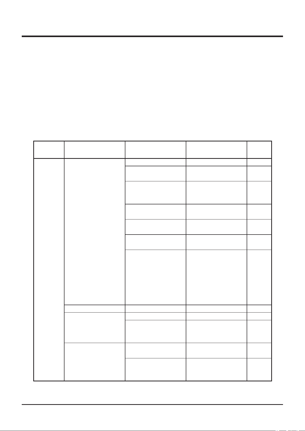
Troubleshooting
Troubleshooting
• If any malfunction or abnormal condition is found, immediately stop using the
machine and take an appropriate measure according to the Troubleshooting chart
below. If the malfunction or abnormal condition is not listed in the chart, or the
suggested measure does not solve the problem, consult with your CANYCOM
representative.
• Some correc tive measures listed below require special knowledge and/or
equipment. Please contact your CANYCOM representative in such a case.
Area Malfunction Possible Cause Corrective Measure Ref.
Out of fuel. →Fill fuel. Page 17
Engine
Excessive fuel in the
engine.
Battery capacity is
insufcient.
Battery cable is
disconnected.
Engine does not start,
or is difcult to start
Engine stalls. Out of fuel. →Fill fuel. Page 17
Engine stops abruptly.
Idling is not stable.
Insufcient or wrong
oil.
Dirty or damaged spark
plug.
Other (other than the
above).
Out of fuel →Fill fuel. Page 17
Other (other than the
above).
Insufcient intake air
(clogged air cleaner).
Other (other than the
above).
→Wait a while and try
starting again.
→Add battery uid.
→Charge battery.
→Replace battery.
→Connect the battery
cable.
→Fill or change oil. Page 55
→Clean or replace the
spark plug.
→Follow the
instructions in
"Starting" to restart.
If problem persists,
please contact
your CANYCOM
representative.
→Please contact
your CANYCOM
representative.
→Clean or replace the
air cleaner.
→Please contact
your CANYCOM
representative.
6
Page 71
Page 71
Page 58
Page 22
Page 57
-79-
Page 89
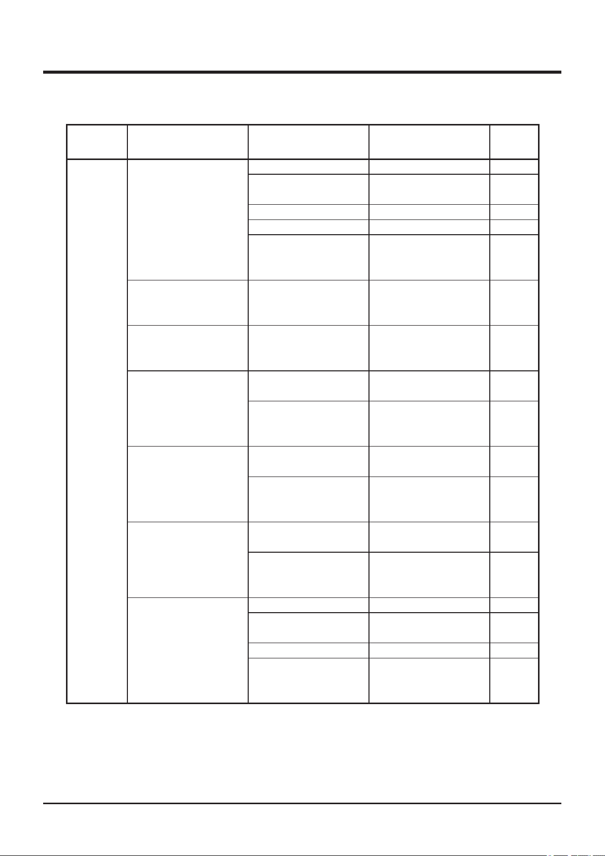
6
Troubleshooting
Area Malfunction Possible Cause Corrective Measure Ref.
Bad fuel →Change fuel.
Engine
Poor power or
acceleration
Irregular noise or
vibration from or
around the engine
Excessive oil
consumption
Engine overheats
Excessive fuel
consumption
Black smoke comes
out of exhaust
White or blue smoke
comes out of exhaust
Insufcient intake air
(clogged air cleaner).
Loose drive belt. →Adjust Page 63
Excessive load →Reduce load.
Other (other than the
above).
Insufcient amount of
engine oil.
Rotating screen
or cooling ns are
clogged or blocked.
Clogged air cleaner. →Clean or replace the
Other (other than the
above).
Clogged air cleaner. →Clean or replace the
Other (other than the
above).
Bad fuel. →Change fuel.
Engine oil level is too
high.
Wrong engine oil. →Change oil. Page 55
Other (other than the
above).
→Clean or replace the
air cleaner.
→Please contact
your CANYCOM
representative.
→Please contact
your CANYCOM
representative.
→Please contact
your CANYCOM
representative.
→Fill oil. Page 55
→Clean.
air cleaner.
→Please contact
your CANYCOM
representative.
air cleaner.
→Please contact
your CANYCOM
representative.
→Adjust the oil level. Page 55
→Please contact
your CANYCOM
representative.
Page 57
Page 57
Page 57
-80-
Page 90
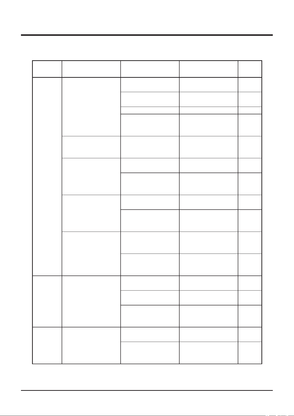
Troubleshooting
Area Malfunction Possible Cause Corrective Measure Ref.
6
Drive Train
Brake
Chassis
Machine does not
move when drive lever
or pedal is operated.
Machine moves when
drive lever or pedal is
in neutral position.
Transmission jumps
out of gear.
Machine does not turn
smoothly.
Machine does not run
straight.
Brake or parking brake
does not work well, or
machine pulls to one
side when braked.
Machine vibrates
abnormally.
Insufcient or
deteriorated HST uid.
Parking brake is
applied
V-belt is loose. →Adjust V-belt. Page 63
Other (other than the
above).
HST is out of neutral. →Please contact
Transmission is not
positively shifted.
Other (other than the
above).
Tires are not properly
inated.
Other (other than the
above).
Tie-rod is not properly
adjusted.
Other (other than the
above).
Brake is not proerly
adjusted.
Brake is wet with water. →Apply brake a few
Other (other than the
above).
Improperly inated
tires.
Other (other than the
above).
→Add or change uid. Page 61
→Release the parking
brake.
→Please contact
your CANYCOM
representative.
your CANYCOM
representative.
→Shift rmly.
→Please contact
your CANYCOM
representative.
→Adjust tire pressure. Page 59
→Please contact
your CANYCOM
representative.
→Please contact
your CANYCOM
representative.
→Please contact
your CANYCOM
representative.
→Adjust. Page 64
times to dry.
→Please contact
your CANYCOM
representative.
→Adjust tire pressure. Page 59
→Please contact
your CANYCOM
representative.
-81-
Page 91
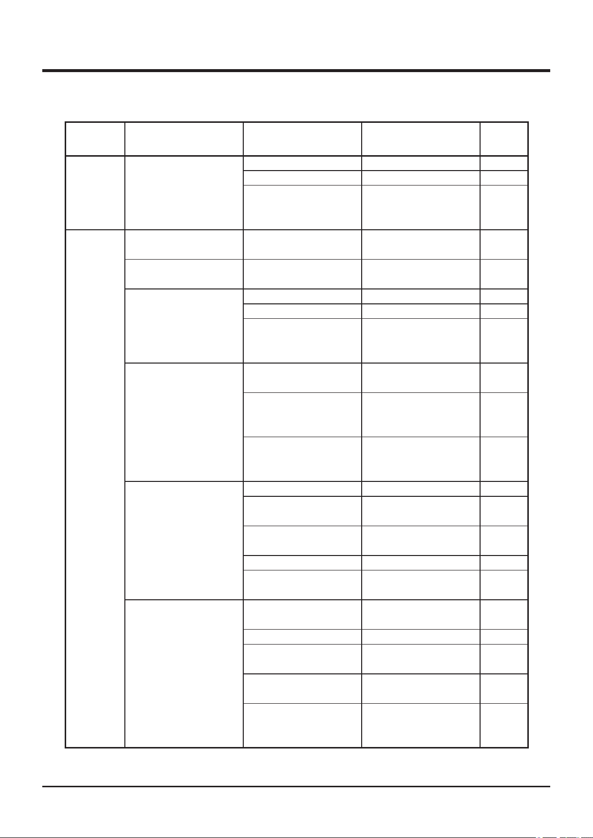
6
Troubleshooting
Area Malfunction Possible Cause Corrective Measure Ref.
Blown bulb. →Replace bulb. Page 73
Electrical
System
Cutting
System
Head lamp does not
illuminate properly.
Cutting blade does not
rotate
Cutting blade does not
stop
Cutting rotary drive
belt slips.
Abnormal vibration
occurs when cutting
blade is rotated..
Cut grass is not
discharged properly.
Some grass is left
uncut.
Blown fuse. →Replace fuse. Page 73
Other (other than the
above).
Cutting rotary drive
belt is severed.
Brake lining is worn. →Replace.
Belt is loose. →Adjust belt tension. Page 68
Belt is worn. →Replace. Page 68
Cut grass or vines
accumulate in the
cutting blade shield.
Cutting blade is
damaged or lost.
Foreign object is
caught by cutting
blade.
Other (other than the
above).
Grass is wet. →
Grass is too long. →Cut in several steps
Cutting height is too
low.
Engine speed is too low.
Driving speed is too
high.
Grass is too long. →Cut in several steps
Engine speed is too low.
Driving speed is too
high.
Cutting blade is
damaged or worn.
Cut grass or vines
accumulate in the
cutting blade shield.
→Please contact
your CANYCOM
representative.
→Replace.
→Clean. Page 75
→Replace cutting
blades.
→Remove or clean
foreign object.
→Please contact
your CANYCOM
representative.
Cut when grass is dry.
at different heights.
→Raise cutting height.
→Raise engine speed.
→Drive slow.
at different heights.
→Raise engine speed.
→Drive slow.
→Replace.
→Clean. Page 75
Page 65
-82-
Page 92
Troubleshooting
Area Malfunction Possible Cause Corrective Measure Ref.
6
Cutting
System
Cutting blade cuts into
ground.
Cutter load is too high.
Cutting height is too
low.
Machine turns too fast. →Turn slowly.
Work site has
undulations.
Cutting blade (knives
or stay) is bent.
Engine speed is too low.
Driving speed is too
high.
Cut grass or vines
are tangled to cutting
blade axle.
→Raise cutting height.
→Raise cutting height.
→Replace.
→Raise engine speed.
→Drive slow.
→Untangle.
-83-
Page 93
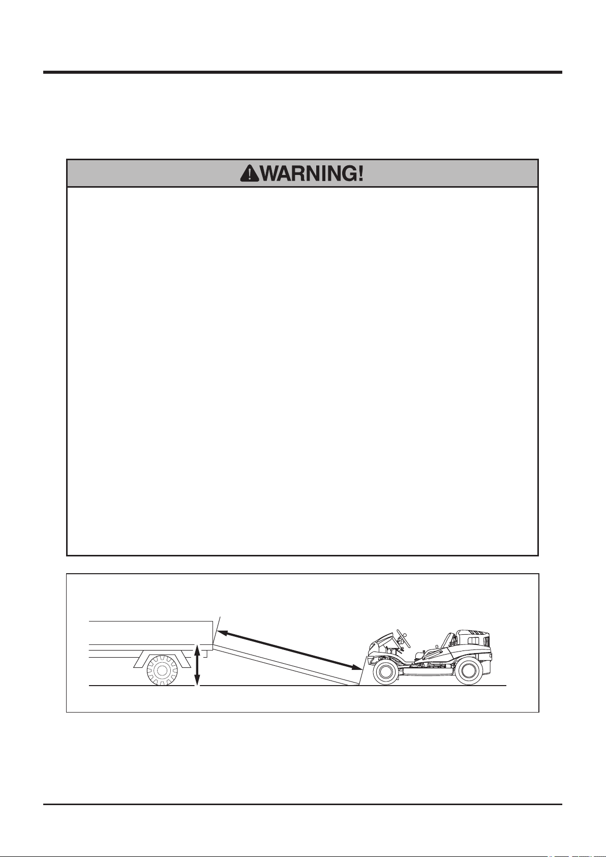
7
Hauling
Loading and Unloading
• Park transporter (truck) on a level ground. Always apply parking brake and use
chocks to secure wheels.
• Do not allow bystandars to come close to machine or transporter when loading
or unloading machine.
• Use only loading ramps with sufficient strength (to withstand the combined
weight of machine and operator), width (more than twice the width of tire.), and
length (more than 4 times the height of loading deck of transporter), and have
Transporting
anti-slip ramp surfaces.
• Secure the hooks of loading ramps rmly and ush with loading deck.
• Move slowly forward when loading onto, and move slowly backward when
unloading off of transporter. Pay special care when going over the joint between
loading deck and ramps; machine may tip.
• Do not turn on loading ramps. Machine may fall.
• Tie down machine securely. Make sure machine does not move around.
More than 4 times
the height
Height
5332M-0701-010E
1. Park the transporter on a level ground. Apply parking brake and secure wheels with
chocks.
-84-
Page 94
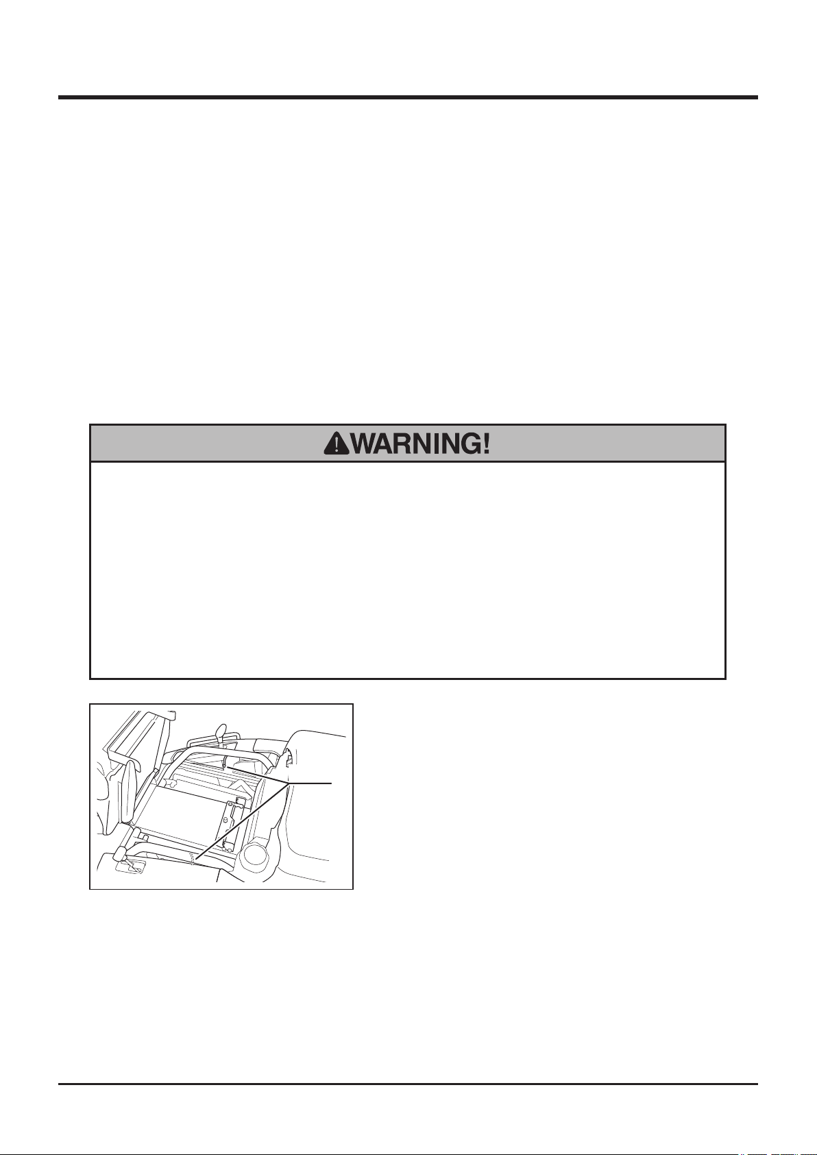
Transporting
2. Place loading ramps. Secure hooks oframps rmly and ush with loading deck.
3. Shift auxiliary transmission shift lever to [Low] and drive machine slowly forward onto
loading deck. Set cutting height adjust lever to [150] for CMX227, CM226, and [130] for
CMX186, CM185. Pay attention not to hit loading lamp or loading deck when loading on
a transporter.
4. Park machine according to the instructions in "Parking" (Page 32). Tie machine with
rope or tie-down belts and secure it onto loading deck of transporter securely.
Hoisting
7
• Licence or certification is required to operate a crane. Check your local
regulations.
• Use hoisting sling of sufficient strength. Always use the slings of the same
length when more than one is used.
• Pay special attention to the center of gravitiy and the balance of machine when
hoisting.
1. Lift seat.
2. Attach hoisting slings to 2 lift hooks and hoist
machine.
Hooks
5332M-0702-010E
-85-
Page 95
NOISE LEVEL
Model
Engine
Type Type Speed rpm
CMX227 / CM226 Robin EH65DS 3300 rpm 100 dB (A)
CMX186 / CM185 Robin EH63DS 3300 rpm 100 dB (A)
NOISE LEVEL evaluated based on factory standard.
VIBRATION
Vibration
Model
Engine
Rated revolution
CMX227 / CM226 3000 rpm
CMX186 / CM185 3000 rpm
Mower Blade
Clutch
ON 22 m/s
OFF 13m/s
ON 19m/s
OFF 11m/s
Steering
wheel (top)
2
2
2
2
Steering
wheel
(bottom)
20 m/s
18 m/s
16m/s
16m/s
2
2
2
2
LwA
Seat
2.5 m/s
2.3 m/s
3.0m/s
2.6m/s
2
2
2
2
VIBRATION evaluated based on factory standard.
 Loading...