

CanyCom CM1801, CM1305 Operator's Manual

CHIKUSUI CANYCOM, INC.
90-1 Fukumasu, Yoshii-machi,
Ukiha-shi, Fukuoka, Japan 839-1396
Tel. (0943)75-2195 Fax.(0943)75-4396
Read and understand this manual completely before attempting
to operate, maintain, and inspect this machine.
Keep this manual with care so that it may be consulted in oper-
ating, maintaining, or inspecting this machine.
WARNING
Ride on Mower
CM1801/CM1305
OPERATOR'S MANUAL
5309 5201 000

NOTICE TO THE USER
Thank you for purchasing our product.
Please read and understand the comments of this manual for proper operation before
using this machine.
The user must know that this machine can be potentially dan-
gerous. Always follow the instructions in this manual when oper-
ating, maintaining, or inspecting the machine.
WARNING
This machine is a work vehicle for mowing. Do not use it for
other purposes. Driving this machine on a public road (or its
equivalent) may be illegal. CHIKUSUI CANYCOM, INC. does
not bear responsibility for accidents or violations of local regulations.
WARNING
Do not remodel the machine. Do not remove the safety cover
when operating, or they may cause serious accidents.
WARNING

CONTENTS
1. INTRODUCTION 1
1.1 PURPOSE OF THIS MANUAL ...................................... 1
1.2 CONTENTS .......................................................... 1
1.3 SAFETY INSTRUCTION IN THIS MANUAL ....................... 2
1.4 WARNING LABELS ATTACHED TO THIS MACHINE ............. 3
2. WARRANTY AND AFTER-SALES SERVICE 4
3. RULES FOR SAFE OPERATION AND WORK 5
4. NAME AND FUNCTION OF COMPONENTS 9
5. SPECIFICATIONS 11
5.1 SPECIFICATIONS FOR THIS MACHINE ......................... 11
5.2 DETAILS ABOUT TOOL BAG ...................................... 12
6. OPERATION 13
6.1 PREPARATIONS FOR OPERATION .............................. 13
6.1.1 Fuel Handling ........................................................ 13
6.1.2 Inspection & Refilling Engine Oil ........................................ 14
6.1.3 Inspection & Refilling HST Oil
.......................................... 14
6.2 STARTING ........................................................... 15
6.3 OPERATION PROCEDURE ....................................... 19
6.4 STOPPING PROCEDURE ......................................... 20

7. MAINTENANCE 25
7.1 REGULAR INSPECTION CHART ................................. 25
7.2 OIL/GREASE/LUBRICANT/FLUID LIST .......................... 28
7.3 CONSUMABLES (SERVICE PARTS) LIST ....................... 29
7.4 LUBRICATION ...................................................... 30
7.4.1 Engine Oil ........................................................... 30
7.4.2 Transmission Oil ...................................................... 31
7.4.3 HST Oil .............................................................. 32
7.5 LUBRICATION AND GREASING .................................. 33
7.5.1 Lubrication ........................................................... 33
7.5.2 Greasing ............................................................ 34
7.6 POURING BATTERY FLUID ....................................... 35
7.6.1 Battery Fluid
......................................................... 35
7.7 CLEANING .......................................................... 37
7.7.1 Air Cleaner Element ................................................... 37
7.7.2 Spark Plug ........................................................... 38
7.7.3 Fuel Cock (Fuel Filter) ................................................. 39
7.7.4 Blower Housing and Cooling Fan ....................................... 40
7.8 ADJUSTMENT ...................................................... 41
7.8.1 V Belt for Driving ..................................................... 41
7.8.2 Blade Rotary V Belt ................................................... 41
7.8.3 Rotary Stopper ....................................................... 41
7.8.4 Brake Pedal .......................................................... 42
7.8.5 HST Lever ........................................................... 42
7.8.6 Tire Pressure ........................................................ 42
6.5 HOW TO PARK ..................................................... 21
6.6 HOW TO TRANSPORT THE MACHINE IN CASE OF
EMERGENCY ....................................................... 21
6.7 HOW TO AVOID REAR WHEEL SLIPPAGE ...................... 22
6.8 ADJUSTMENT OF STEERING WHEEL HEIGHT ................ 22
6.9 HOW TO OPERATE BLADE ....................................... 23

9. TROUBLESHOOTING 48
9.1 TROUBLESHOOTING CHART .....................................48
10.
TRANSPORTATION OF/WITH THIS VEHICLE 53
<Guarantee certificate>
Attached to the end of this manual.
* Receive the guarantee certificate together with a receipt after you have received
instructions for handling of this machine.
<Appendix>
"Instruction manual for engine" (Included in the tool bag)
* Be sure to read it together with this manual.
8. STORAGE (LONG-TERM) 45
8.1 VEHICLE BODY .................................................... 45
8.2 BATTERY ............................................................ 46
8.3 ENGINE ............................................................. 46
8.3.1 Fuel Cock ............................................................ 46
8.3.2 Cleaning Air Cleaner Element
......................................... 47
8.3.3 Replacing Engine Oil .................................................. 47
7.9 REPLACEMENT .................................................... 43
7.9.1 Oil filter (CM1801) ..................................................... 43
7.9.2 Fuel Pipe, Engine Oil Drain Pipe, and HST Oil Tank Connection Hose ....... 43
7.9.3 HST Oil filter (CM1801) ................................................ 43
7.9.4 Blade ............................................................... 43
7.10 AFTER-USE MAINTENANCE ..................................... 44

1
INTRODUCTION
– 1 –
1. INTRODUCTION
1.1 PURPOSE OF THIS MANUAL
The purpose of this manual is to provide the user with appropriate information in detail about how to operate,
maintain, and inspect this machine.
This manual has been prepared for people who use this machine for the first time.
1.2 CONTENTS
This manual gives information by dividing it into the following chapters.
1. INTRODUCTION
This chapter explains the purpose and contents of this manual and warning terms used in this manual.
It also includes the description of warning labels attached to this machine.
2. WARRANTY AND AFTER-SALES SERVICE
This chapter describes the warranty and after-sales service for this machine.
3. RULES FOR SAFE OPERATION AND WORK
This chapter describes the general safety rules which the user must observe when operating and working.
4. NAME AND FUNCTION OF COMPONENTS
This chapter explains the names and functions of the component parts.
5. SPECIFICATIONS
This chapter describes the specifications of this machine. It also describes the details about the tool
bag.
6. OPERATION
This chapter explains the preparations before operation, operating procedure, and how to use the control devices.
7. MAINTENANCE
This chapter gives information about maintenance such as regular inspection, supplying oil, grease,
lubricant, and fluids, cleaning, adjustments, and after-use maintenance.
8. STORAGE (LONG-TERM)
This chapter gives information about the storage (long-term storage) of this machine.
9. TROUBLESHOOTING
This chapter describes the troubleshooting on this machine.
10. TRANSPORTATION OF/WITH THIS VEHICLE
This chapter explains the procedures and precautions for transporting this machine.

1
INTRODUCTION
– 2 –
1.3 SAFETY INSTRUCTION IN THIS MANUAL
In this manual, safety information is classified into the following four categories according to the degree of
hazard (seriousness of possible accidents). Read and understand the contents below and always observe the
safety instructions in this manual.
Category Meaning
Indicates an extremely hazardous situation which will result in death or serious
injury if the user does not follow appropriate instructions.
Indicates a potentially hazardous situation which could result in death or serious
injury if the user does not follow appropriate instructions.
Indicates a potentially hazardous situation which could result in injury to the user
or damage to the machine if the user does not follow appropriate instructions.
Used to emphasize information which needs particular attention.
CAUTION
WARNING
DANGER
NOTE

1
INTRODUCTION
– 3 –
1.4 WARNING LABELS ATTACHED TO THIS MACHINE
The warning labels shown below are attached to this machine. When warning labels have come off or become
difficult to see, order new ones from a dealer by the part numbers shown below labels and attach them.

2
2. WARRANTY AND AFTER-SALES SERVICE
CONCERNING WARRANTY
Our company guarantees this product based on the contents of the written warranty. For more information, refer to
the written warranty attached to the end of this manual.
CONCERNING AFTER-SALES SERVICE
Please feel free to consult with the store of purchase or with our company's sales department in regard to service
orders or in case trouble or questions arise during the course of using the unit. At such times, please be prepared to
report the product model and product's serial number shown in the model label, as well as the names of the manufacturer and model of the engine installed. (For the names of the manufacturer and model of the engine installed,
refer to Chapter 5 "SPECIFICATIONS" in this manual. Page 11 )
<Location of model label> <Model label>
CM1801
Product model
product's se Serial number
CM1305
Product model
Serial number
CONCERNING THE TERM (PERIOD) OF SUPPLY OF REPAIR PARTS
The term (period) of supply of repair parts for this product shall be seven years after manufacturing is discontinued.
– 4 –
WARRANTY AND AFTER-SALES SERVICE
Location of model label
CM1801
CHIKUSUI CANYCOM. INC
Product No.
CM1305
CHIKUSUI CANYCOM. INC
Product No.
SAFETY PRECAUTIONS BEFORE OPERATION
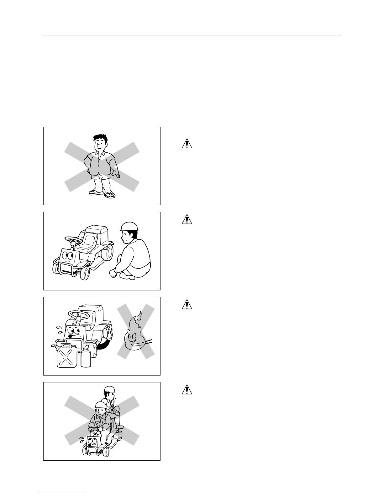
PROTECTIVE CLOTHING
Make it a rule to wear clothes suitable for driving and operation. Do not be lightly dressed or do not wear sandals, etc. in
carrying out driving and operation.
PRE-WORK CHECK
Carry out the daily pre-check before starting the machine.
Repair or replace defective parts before use.
FUEL HANDLING
When handling fuel or grease, never bring fire (cigarette fire,
etc.) to it. Also, be very careful of fire when charging the battery or servicing the engine.
NEVER CARRY PASSENGERS
The seating capacity of this machine is only one for the operator. It is extremely dangerous to drive this machine with a
fellow passenger or passengers on it, because movements of
the center of gravity, etc. occur. Never allow a person or persons other than the operator to ride on the machine.
– 5 –
3
RULES FOR SAFE OPERATION AND WORK
3. RULES FOR SAFE OPERATION AND WORK
This chapter shows the general safety precautions to be observed during driving or operation. Try to carry out
driving or operation safely by being sure to follow the safety instructions in other chapters as well.
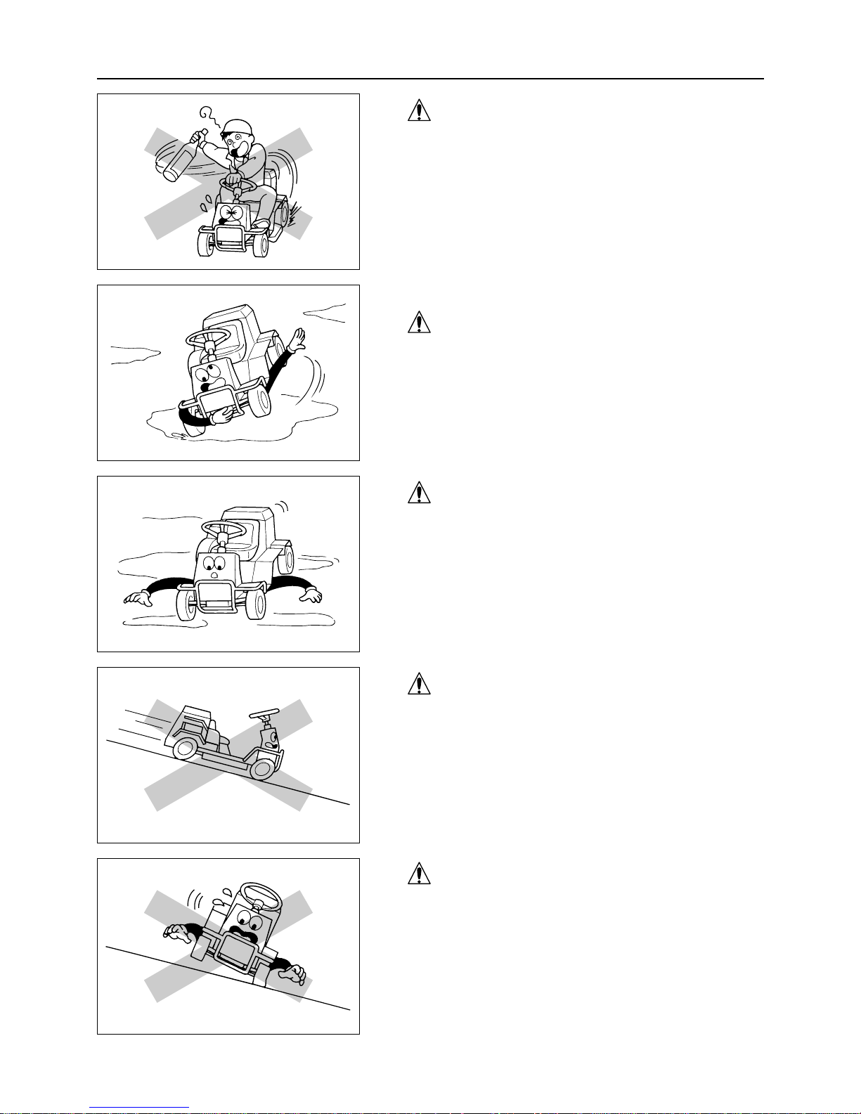
PRECAUTIONS WHEN DRIVING THE MOWER
PROHIBIT QUICK STARTING, ACCELERATING,
TURNING AND BRAKING
Avoid quick starting, sudden accelerating, sharp turns and
braking. Always drive safely. Before driving ensure the area
around the machine is safe. On soft and wet ground never try
sudden or sharp turning or stops, as this may cause the
machine to slip or turnover.
OBSERVE SAFE SPEED
Drive at safe speeds on a slope in accordance with the conditions.
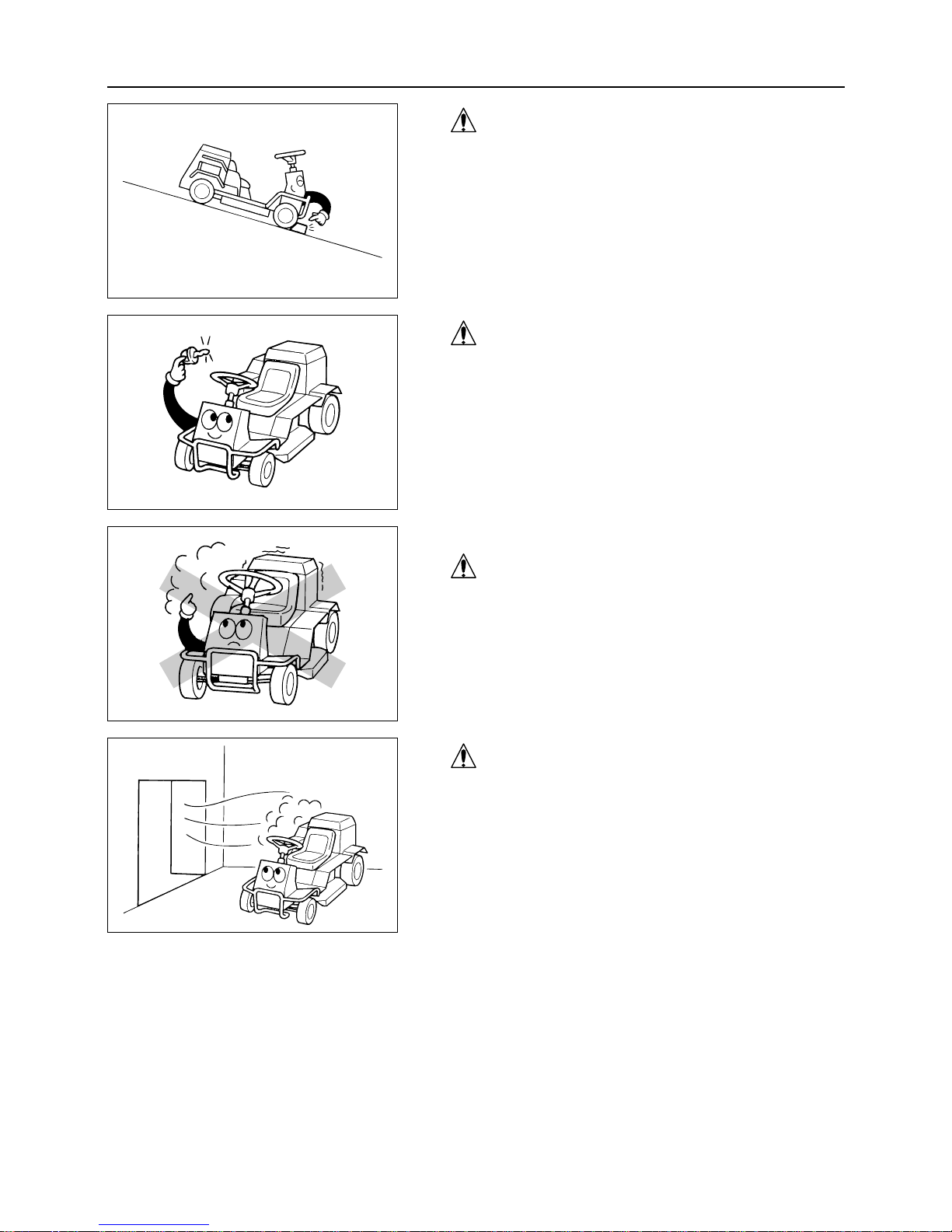
ENGINE BRAKE ON DOWN HILL
When driving down a slope, stop once before going down
and set the aux. speed change lever to the "Low" position.
Use engine brake.
DO NOT DRIVE ACROSS SLOPES
On slopes go straight up or down within the limits of
machine gradeability. Driving across slopes is dangerous.
– 6 –
3
RULES FOR SAFE OPERATION AND WORK
PROHIBIT RECKLESS DRIVING
Do not drive when drinking alcoholic drinks or when your
physical conditions are bad.
Also, do not let unauthorized young people drive the
machine.

SAFETY PRECAUTIONS WHEN OPERATING
DO NOT OPERATE IN DANGEROUS PLACES
Remove all obstacles. Do not operate on steep slopes or soft
and rough ground and avoid dangerous places.
SECURE AREA (NO ADMlTTANCE) DURING
OPERATION
Post notice boards before that operating that job site is under
operation. If necessary, apply guard ropes to enclose and
restrict access so that people (especially children) may not
enter the work area and safety may be ensured.
BEWARE OF FLYING OBJECTS
During operation make sure that stones and small objects are
not discharged to nearby persons, animals, crops, cars or
other objects.
PRECAUTIONS WHEN PARKING
DO NOT PARK IN DANGEROUS PLACES
Park the machine on stable, flat ground. Avoid parking in
dangerous places.
– 7 –
3
RULES FOR SAFE OPERATION AND WORK
PRECAUTIONS OF CRUMBLING GROUND
Beware of driving trenches and banks. There is a danger of
the ground crumbling due to the machine weight. If travelling
on soft ground, drive slowly and safely.
3
SAFETY CONFIRMATION WHEN PARKING
When parking always apply brake and stop engine.
Always remove key.
PRECAUTIONS WHEN SERVICING
DO NOT SERVICE WHEN THE ENGINE IS RUNNING
Do not service the mower while the engjne is running.
Always do service work after stopping engine.
PRECAUTIONS FOR VENTILATION
When operating the engine indoors make sure that there is
enough ventilation to prevent poisoning due to exhaust gas.
– 8 –
RULES FOR SAFE OPERATION AND WORK
ALWAYS APPLY BRAKES ON SLOPES
Avoid parking on slopes. If parking on a slope is unavoidable, apply brakes and wheel blocks.

4. NAME AND FUNCTION OF COMPONENTS
NAMES OF COMPONENTS
4
NAME AND FUNCTION OF COMPONENTS
– 9 –
Differential lock lever
HST lever
Accelerator lever
Blade height adjusting lever
(Blade height adjustment)
Blade clutch lever
Parking brake lock lever
Brake pedal
AUX. speed change lever
Cover
Forward
Reverse
Grass outlet
Headlamp switch
Main switch

4
NAME AND FUNCTION OF COMPONENTS
– 10 –
FUNCTIONS OF COMPONENTS
Main switch ............................Start the engine or stall the engine with this switch by means of
remote control.
When the machine is not used remove and keep the key.
Accelerator lever .......................Increases and decreases engine speed.
Choke lever ............................When the lever is pulled, the choke valve closes, and when it is
returned, the choke valve opens. Pull the lever when starting the
engine and return it after the engine is started.
(In the case of CM1305, the choke lever is connected with the accelerator lever.)
HST lever ..............................The HST lever changes the discharge of the hydraulic pump in the
HST and changes the advancing direction and travelling speed in a
stepless way.
When pushing the lever forward from neutral position the machine
starts to move forward. Pulling the lever in reverse makes machine
drive backward. Speed increases as lever is depressed in either direction.
AUX. speed change lever ...............Use this lever when shifting speed to high/low levels.
Speed shift can be used while driving.
Brake pedal ............................Use to stop the machine.
When depressing brake pedal HST lever returns to neutral and stops
the machine.
Differential lock lever ..................Use this lever when slipping one side of the rear wheels.
When lever is pushed to "ON", the differential lock is engaged.
When lever is "OFF", the differential lock is released (normal driving
position).
During normal driving always put the lever to "OFF" position.
Light switch ............................Headlamp is turned on when switch is pulled.
Parking brake lock lever ................After stopping the machine, pull the lock lever downward to lock
brake pedal.
Blade height adjusting lever ..............Adjusts the height of blade (5 steps)
Blade clutch lever ......................Turns on and off the power of blade.
When putting this lever to "OFF" position, the cutter brake pulley is
engaged and the brake is applied.
Grass outlet ............................Secure area around machine before opening. Opening outlet allows
cut grass to be easily removed. Open outlet when changing cutter
blade.
Outlet should be closed during normal use to prevent stones and
other objects from being thrown from machine.

5
SPECIFICATIONS
– 11 –
5. SPECIFICATIONS
5.1 SPECIFICATIONS FOR THIS MACHINE
Use this product properly after understanding the specifications
for this product.
NOTE
MODEL CM1305 CM1801
MACHINE WEIGHT kg 255 260
APPLICABLE JOB AREA m2/h 4500 9000
O VERALL LENGTH mm 1840 1870
O VERALL WIDTH mm 995
O VERALL HEIGHT mm 885
WHEEL BASE mm 1200
TREAD mm Front 800, Rear 735
MINIMUM FREEBOARD mm 105
MODEL GH400V/GM400PV FH531V
T Y P E
Air-cooled 4-cycle gasoline
Air-cooled 4-cycle gasoline
V twin
CYLINDER mm
84
70 68 68
(BORE X STROKE)
TOTAL DISPLACEMENT cm3(cc) 389 (389) 494 (494)
MAXIMUM OUTPUT 9.56/4000 (13.0/4000) 13.3/3600 (18.0/3600)
STARTING SYSTEM Self-starting system
FUEL USED Gasoline
FUEL TANK CAPACITY 11
LUBRICATING OIL
1.4 1.5
CAPACITY
BATTERY TYPE V/AH 28A19R 38B19R
BATTERY CAPACITY 12/21 12/28
IGNITION SYSTEM Electronic ignition
IGNITION PLUG NO. BP4HS-10 RCJ8Y
MACHINE DIMENSIONS
kW/min
-1
(PS/rpm)
ENGINE

5
SPECIFICATIONS
– 12 –
*We reserve the right to change the specifications without prior notice.
5.2 DETAILS ABOUT TOOL BAG
MODEL CM1305 CM1801
F
(FORWARD)
HST(Variable speed)
R
(REVERSE)
HST(Variable speed)
HIGH SPEED km/h 0 10.7
LOW SPEED km/h 0 5.9
LEFT degree 45
RIGHT degree 45
MINIMUM TURN RADIUS
m 1.9
GRADEABILITY degree 15
AMOUNT OF TRANSMISSION OIL
1.2
MAIN SPEED CHANGE
HST
TYPE
STEERING DEVICE Rack and pinion type round steering wheel
BRAKE TYPE Internal expanding type brake
T I R EFront AGR3.50–7, Rear 16 7.00–8
CUTTER BLADE WIDTH mm 90 0
CUTTER BLADE HEIGHT
mm 0 to 75 (5 steps)
CUTTER BLADE TYPE
Knife to be used both as a free one and a fixed one, and
stay with steps
NUMBER OF
STAGES
No. Part name Quantity Remarks
1 Operator's manual (This document) 1
2 Instruction manual for engine 1
3 Engine tools 1 set For engine servicing
TRAVELLING PERFORMANCE
TRAVELLING SPEED
POWER TRANSMIS-
SION DEVICE
STABILITY
INCLINATION
ANGLE
CUTTER BLADE
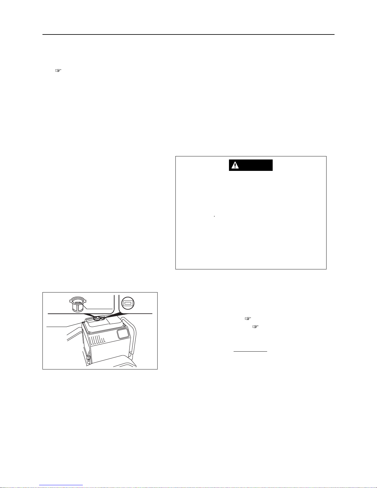
6.1 PREPARATIONS FOR OPERATION
6.1.1 Fuel Handling
•Petrol (gasoline) fuel is flammable. Never
refuel or service the fuel system while smoking or when near open flames or sparks.
•Never refuel the machine when the engine is
running
• After stopping engine, the engine becomes
hotter. Therefore fuel must be handled with
great care when refueling. Do not spill fuel
out of filler cap.
DANGER
1. Check the fuel gauge visually. If fuel is not reserved
enough, open the filler cap and pour fuel.
Fuel to be used : page 28
Fuel tank capacity : page 28
• When fuel gauge needle approaches empty
"E", refuel as soon as possible.
• When using the unit on slopes, refuel less
than the upper fuel limit for the fuel filter in
the lubrication port.
2. Close the filler cap firmly after refueling
NOTE
– 13 –
6
OPERATION
6. OPERATION
• Before reading this chapter, be sure to read "RULES FOR SAFE OPERATION AND WORK" in Chapter 3
(pages 5 to 8).
• Concerning the operation and control, be sure to follow the instructions given in this chapter. If you do not
have a complete understanding of the operating and control system or safety devices, never operate the
machine based on your own judgment.
Fuel
filter
Fuel
gauge
Upper limit
of oil level
Filler cap
 Loading...