

Page 1

CHIKUSUI CANYCOM, INC.
90-1 Fukumasu, Yoshii-machi,
Ukiha-shi, Fukuoka, Japan 839-1396
Tel. (0943)75-2195 Fax.(0943)75-4396
Read and understand this manual completely before attempting
to operate, maintain, and inspect this machine.
Keep this manual with care so that it may be consulted in oper-
ating, maintaining, or inspecting this machine.
WARNING
Ride on Mower
CM1801/CM1305
OPERATOR'S MANUAL
5309 5201 000
Page 2

NOTICE TO THE USER
Thank you for purchasing our product.
Please read and understand the comments of this manual for proper operation before
using this machine.
The user must know that this machine can be potentially dan-
gerous. Always follow the instructions in this manual when oper-
ating, maintaining, or inspecting the machine.
WARNING
This machine is a work vehicle for mowing. Do not use it for
other purposes. Driving this machine on a public road (or its
equivalent) may be illegal. CHIKUSUI CANYCOM, INC. does
not bear responsibility for accidents or violations of local regulations.
WARNING
Do not remodel the machine. Do not remove the safety cover
when operating, or they may cause serious accidents.
WARNING
Page 3

CONTENTS
1. INTRODUCTION 1
1.1 PURPOSE OF THIS MANUAL ...................................... 1
1.2 CONTENTS .......................................................... 1
1.3 SAFETY INSTRUCTION IN THIS MANUAL ....................... 2
1.4 WARNING LABELS ATTACHED TO THIS MACHINE ............. 3
2. WARRANTY AND AFTER-SALES SERVICE 4
3. RULES FOR SAFE OPERATION AND WORK 5
4. NAME AND FUNCTION OF COMPONENTS 9
5. SPECIFICATIONS 11
5.1 SPECIFICATIONS FOR THIS MACHINE ......................... 11
5.2 DETAILS ABOUT TOOL BAG ...................................... 12
6. OPERATION 13
6.1 PREPARATIONS FOR OPERATION .............................. 13
6.1.1 Fuel Handling ........................................................ 13
6.1.2 Inspection & Refilling Engine Oil ........................................ 14
6.1.3 Inspection & Refilling HST Oil
.......................................... 14
6.2 STARTING ........................................................... 15
6.3 OPERATION PROCEDURE ....................................... 19
6.4 STOPPING PROCEDURE ......................................... 20
Page 4

7. MAINTENANCE 25
7.1 REGULAR INSPECTION CHART ................................. 25
7.2 OIL/GREASE/LUBRICANT/FLUID LIST .......................... 28
7.3 CONSUMABLES (SERVICE PARTS) LIST ....................... 29
7.4 LUBRICATION ...................................................... 30
7.4.1 Engine Oil ........................................................... 30
7.4.2 Transmission Oil ...................................................... 31
7.4.3 HST Oil .............................................................. 32
7.5 LUBRICATION AND GREASING .................................. 33
7.5.1 Lubrication ........................................................... 33
7.5.2 Greasing ............................................................ 34
7.6 POURING BATTERY FLUID ....................................... 35
7.6.1 Battery Fluid
......................................................... 35
7.7 CLEANING .......................................................... 37
7.7.1 Air Cleaner Element ................................................... 37
7.7.2 Spark Plug ........................................................... 38
7.7.3 Fuel Cock (Fuel Filter) ................................................. 39
7.7.4 Blower Housing and Cooling Fan ....................................... 40
7.8 ADJUSTMENT ...................................................... 41
7.8.1 V Belt for Driving ..................................................... 41
7.8.2 Blade Rotary V Belt ................................................... 41
7.8.3 Rotary Stopper ....................................................... 41
7.8.4 Brake Pedal .......................................................... 42
7.8.5 HST Lever ........................................................... 42
7.8.6 Tire Pressure ........................................................ 42
6.5 HOW TO PARK ..................................................... 21
6.6 HOW TO TRANSPORT THE MACHINE IN CASE OF
EMERGENCY ....................................................... 21
6.7 HOW TO AVOID REAR WHEEL SLIPPAGE ...................... 22
6.8 ADJUSTMENT OF STEERING WHEEL HEIGHT ................ 22
6.9 HOW TO OPERATE BLADE ....................................... 23
Page 5

9. TROUBLESHOOTING 48
9.1 TROUBLESHOOTING CHART .....................................48
10.
TRANSPORTATION OF/WITH THIS VEHICLE 53
<Guarantee certificate>
Attached to the end of this manual.
* Receive the guarantee certificate together with a receipt after you have received
instructions for handling of this machine.
<Appendix>
"Instruction manual for engine" (Included in the tool bag)
* Be sure to read it together with this manual.
8. STORAGE (LONG-TERM) 45
8.1 VEHICLE BODY .................................................... 45
8.2 BATTERY ............................................................ 46
8.3 ENGINE ............................................................. 46
8.3.1 Fuel Cock ............................................................ 46
8.3.2 Cleaning Air Cleaner Element
......................................... 47
8.3.3 Replacing Engine Oil .................................................. 47
7.9 REPLACEMENT .................................................... 43
7.9.1 Oil filter (CM1801) ..................................................... 43
7.9.2 Fuel Pipe, Engine Oil Drain Pipe, and HST Oil Tank Connection Hose ....... 43
7.9.3 HST Oil filter (CM1801) ................................................ 43
7.9.4 Blade ............................................................... 43
7.10 AFTER-USE MAINTENANCE ..................................... 44
Page 6

1
INTRODUCTION
– 1 –
1. INTRODUCTION
1.1 PURPOSE OF THIS MANUAL
The purpose of this manual is to provide the user with appropriate information in detail about how to operate,
maintain, and inspect this machine.
This manual has been prepared for people who use this machine for the first time.
1.2 CONTENTS
This manual gives information by dividing it into the following chapters.
1. INTRODUCTION
This chapter explains the purpose and contents of this manual and warning terms used in this manual.
It also includes the description of warning labels attached to this machine.
2. WARRANTY AND AFTER-SALES SERVICE
This chapter describes the warranty and after-sales service for this machine.
3. RULES FOR SAFE OPERATION AND WORK
This chapter describes the general safety rules which the user must observe when operating and working.
4. NAME AND FUNCTION OF COMPONENTS
This chapter explains the names and functions of the component parts.
5. SPECIFICATIONS
This chapter describes the specifications of this machine. It also describes the details about the tool
bag.
6. OPERATION
This chapter explains the preparations before operation, operating procedure, and how to use the control devices.
7. MAINTENANCE
This chapter gives information about maintenance such as regular inspection, supplying oil, grease,
lubricant, and fluids, cleaning, adjustments, and after-use maintenance.
8. STORAGE (LONG-TERM)
This chapter gives information about the storage (long-term storage) of this machine.
9. TROUBLESHOOTING
This chapter describes the troubleshooting on this machine.
10. TRANSPORTATION OF/WITH THIS VEHICLE
This chapter explains the procedures and precautions for transporting this machine.
Page 7

1
INTRODUCTION
– 2 –
1.3 SAFETY INSTRUCTION IN THIS MANUAL
In this manual, safety information is classified into the following four categories according to the degree of
hazard (seriousness of possible accidents). Read and understand the contents below and always observe the
safety instructions in this manual.
Category Meaning
Indicates an extremely hazardous situation which will result in death or serious
injury if the user does not follow appropriate instructions.
Indicates a potentially hazardous situation which could result in death or serious
injury if the user does not follow appropriate instructions.
Indicates a potentially hazardous situation which could result in injury to the user
or damage to the machine if the user does not follow appropriate instructions.
Used to emphasize information which needs particular attention.
CAUTION
WARNING
DANGER
NOTE
Page 8

1
INTRODUCTION
– 3 –
1.4 WARNING LABELS ATTACHED TO THIS MACHINE
The warning labels shown below are attached to this machine. When warning labels have come off or become
difficult to see, order new ones from a dealer by the part numbers shown below labels and attach them.
Page 9

2
2. WARRANTY AND AFTER-SALES SERVICE
CONCERNING WARRANTY
Our company guarantees this product based on the contents of the written warranty. For more information, refer to
the written warranty attached to the end of this manual.
CONCERNING AFTER-SALES SERVICE
Please feel free to consult with the store of purchase or with our company's sales department in regard to service
orders or in case trouble or questions arise during the course of using the unit. At such times, please be prepared to
report the product model and product's serial number shown in the model label, as well as the names of the manufacturer and model of the engine installed. (For the names of the manufacturer and model of the engine installed,
refer to Chapter 5 "SPECIFICATIONS" in this manual. Page 11 )
<Location of model label> <Model label>
CM1801
Product model
product's se Serial number
CM1305
Product model
Serial number
CONCERNING THE TERM (PERIOD) OF SUPPLY OF REPAIR PARTS
The term (period) of supply of repair parts for this product shall be seven years after manufacturing is discontinued.
– 4 –
WARRANTY AND AFTER-SALES SERVICE
Location of model label
CM1801
CHIKUSUI CANYCOM. INC
Product No.
CM1305
CHIKUSUI CANYCOM. INC
Product No.
Page 10
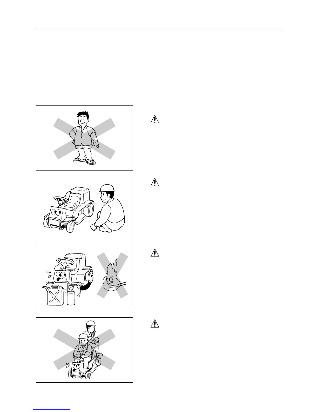
SAFETY PRECAUTIONS BEFORE OPERATION
PROTECTIVE CLOTHING
Make it a rule to wear clothes suitable for driving and operation. Do not be lightly dressed or do not wear sandals, etc. in
carrying out driving and operation.
PRE-WORK CHECK
Carry out the daily pre-check before starting the machine.
Repair or replace defective parts before use.
FUEL HANDLING
When handling fuel or grease, never bring fire (cigarette fire,
etc.) to it. Also, be very careful of fire when charging the battery or servicing the engine.
NEVER CARRY PASSENGERS
The seating capacity of this machine is only one for the operator. It is extremely dangerous to drive this machine with a
fellow passenger or passengers on it, because movements of
the center of gravity, etc. occur. Never allow a person or persons other than the operator to ride on the machine.
– 5 –
3
RULES FOR SAFE OPERATION AND WORK
3. RULES FOR SAFE OPERATION AND WORK
This chapter shows the general safety precautions to be observed during driving or operation. Try to carry out
driving or operation safely by being sure to follow the safety instructions in other chapters as well.
Page 11
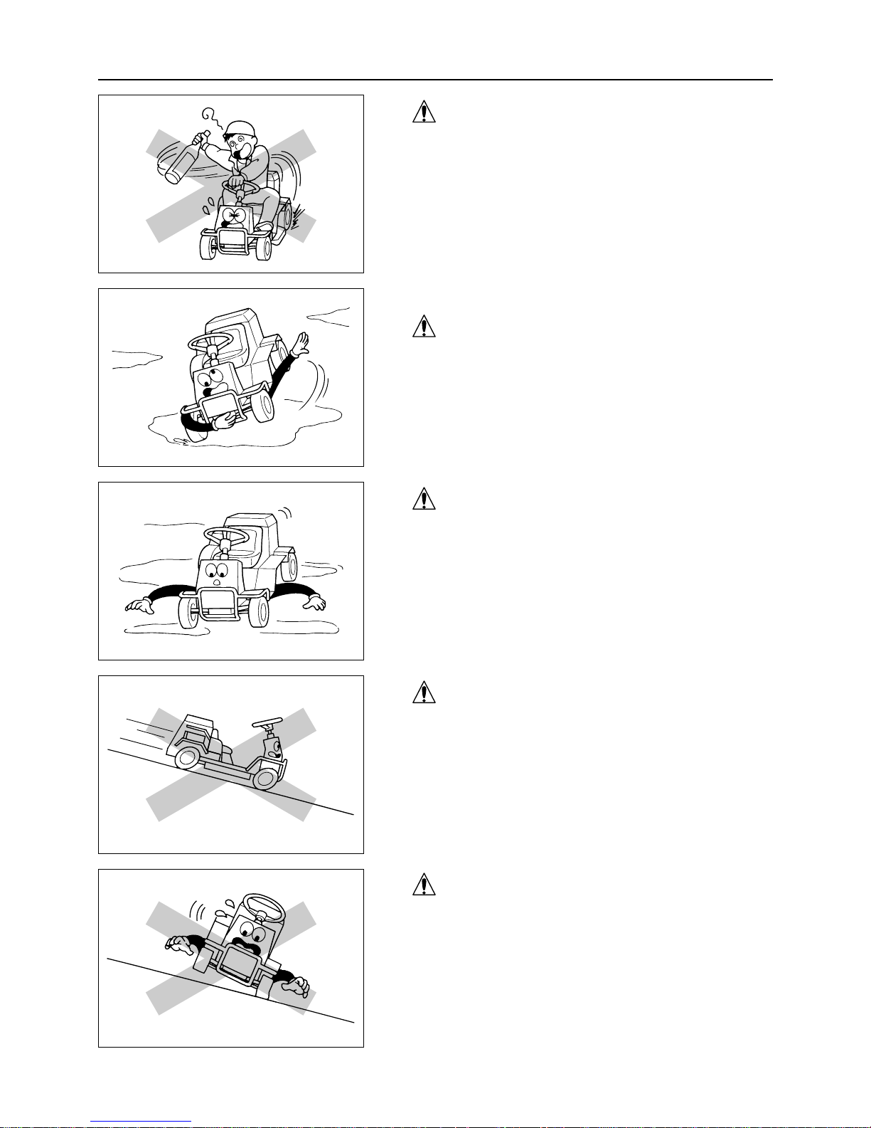
PRECAUTIONS WHEN DRIVING THE MOWER
PROHIBIT QUICK STARTING, ACCELERATING,
TURNING AND BRAKING
Avoid quick starting, sudden accelerating, sharp turns and
braking. Always drive safely. Before driving ensure the area
around the machine is safe. On soft and wet ground never try
sudden or sharp turning or stops, as this may cause the
machine to slip or turnover.
OBSERVE SAFE SPEED
Drive at safe speeds on a slope in accordance with the conditions.
ENGINE BRAKE ON DOWN HILL
When driving down a slope, stop once before going down
and set the aux. speed change lever to the "Low" position.
Use engine brake.
DO NOT DRIVE ACROSS SLOPES
On slopes go straight up or down within the limits of
machine gradeability. Driving across slopes is dangerous.
– 6 –
3
RULES FOR SAFE OPERATION AND WORK
PROHIBIT RECKLESS DRIVING
Do not drive when drinking alcoholic drinks or when your
physical conditions are bad.
Also, do not let unauthorized young people drive the
machine.
Page 12

SAFETY PRECAUTIONS WHEN OPERATING
DO NOT OPERATE IN DANGEROUS PLACES
Remove all obstacles. Do not operate on steep slopes or soft
and rough ground and avoid dangerous places.
SECURE AREA (NO ADMlTTANCE) DURING
OPERATION
Post notice boards before that operating that job site is under
operation. If necessary, apply guard ropes to enclose and
restrict access so that people (especially children) may not
enter the work area and safety may be ensured.
BEWARE OF FLYING OBJECTS
During operation make sure that stones and small objects are
not discharged to nearby persons, animals, crops, cars or
other objects.
PRECAUTIONS WHEN PARKING
DO NOT PARK IN DANGEROUS PLACES
Park the machine on stable, flat ground. Avoid parking in
dangerous places.
– 7 –
3
RULES FOR SAFE OPERATION AND WORK
PRECAUTIONS OF CRUMBLING GROUND
Beware of driving trenches and banks. There is a danger of
the ground crumbling due to the machine weight. If travelling
on soft ground, drive slowly and safely.
Page 13
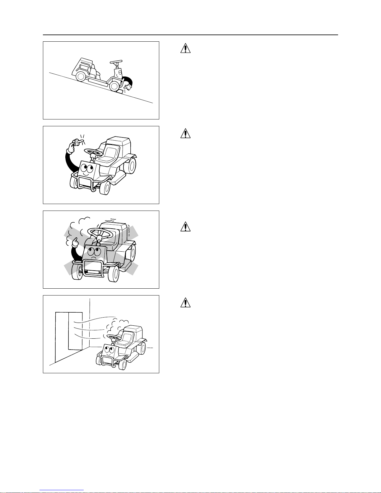
3
SAFETY CONFIRMATION WHEN PARKING
When parking always apply brake and stop engine.
Always remove key.
PRECAUTIONS WHEN SERVICING
DO NOT SERVICE WHEN THE ENGINE IS RUNNING
Do not service the mower while the engjne is running.
Always do service work after stopping engine.
PRECAUTIONS FOR VENTILATION
When operating the engine indoors make sure that there is
enough ventilation to prevent poisoning due to exhaust gas.
– 8 –
RULES FOR SAFE OPERATION AND WORK
ALWAYS APPLY BRAKES ON SLOPES
Avoid parking on slopes. If parking on a slope is unavoidable, apply brakes and wheel blocks.
Page 14

4. NAME AND FUNCTION OF COMPONENTS
NAMES OF COMPONENTS
4
NAME AND FUNCTION OF COMPONENTS
– 9 –
Differential lock lever
HST lever
Accelerator lever
Blade height adjusting lever
(Blade height adjustment)
Blade clutch lever
Parking brake lock lever
Brake pedal
AUX. speed change lever
Cover
Forward
Reverse
Grass outlet
Headlamp switch
Main switch
Page 15

4
NAME AND FUNCTION OF COMPONENTS
– 10 –
FUNCTIONS OF COMPONENTS
Main switch ............................Start the engine or stall the engine with this switch by means of
remote control.
When the machine is not used remove and keep the key.
Accelerator lever .......................Increases and decreases engine speed.
Choke lever ............................When the lever is pulled, the choke valve closes, and when it is
returned, the choke valve opens. Pull the lever when starting the
engine and return it after the engine is started.
(In the case of CM1305, the choke lever is connected with the accelerator lever.)
HST lever ..............................The HST lever changes the discharge of the hydraulic pump in the
HST and changes the advancing direction and travelling speed in a
stepless way.
When pushing the lever forward from neutral position the machine
starts to move forward. Pulling the lever in reverse makes machine
drive backward. Speed increases as lever is depressed in either direction.
AUX. speed change lever ...............Use this lever when shifting speed to high/low levels.
Speed shift can be used while driving.
Brake pedal ............................Use to stop the machine.
When depressing brake pedal HST lever returns to neutral and stops
the machine.
Differential lock lever ..................Use this lever when slipping one side of the rear wheels.
When lever is pushed to "ON", the differential lock is engaged.
When lever is "OFF", the differential lock is released (normal driving
position).
During normal driving always put the lever to "OFF" position.
Light switch ............................Headlamp is turned on when switch is pulled.
Parking brake lock lever ................After stopping the machine, pull the lock lever downward to lock
brake pedal.
Blade height adjusting lever ..............Adjusts the height of blade (5 steps)
Blade clutch lever ......................Turns on and off the power of blade.
When putting this lever to "OFF" position, the cutter brake pulley is
engaged and the brake is applied.
Grass outlet ............................Secure area around machine before opening. Opening outlet allows
cut grass to be easily removed. Open outlet when changing cutter
blade.
Outlet should be closed during normal use to prevent stones and
other objects from being thrown from machine.
Page 16

5
SPECIFICATIONS
– 11 –
5. SPECIFICATIONS
5.1 SPECIFICATIONS FOR THIS MACHINE
Use this product properly after understanding the specifications
for this product.
NOTE
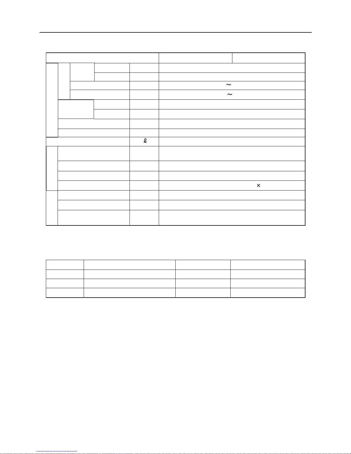
MODEL CM1305 CM1801
MACHINE WEIGHT kg 255 260
APPLICABLE JOB AREA m2/h 4500 9000
O VERALL LENGTH mm 1840 1870
O VERALL WIDTH mm 995
O VERALL HEIGHT mm 885
WHEEL BASE mm 1200
TREAD mm Front 800, Rear 735
MINIMUM FREEBOARD mm 105
MODEL GH400V/GM400PV FH531V
T Y P E
Air-cooled 4-cycle gasoline
Air-cooled 4-cycle gasoline
V twin
CYLINDER mm
84
70 68 68
(BORE X STROKE)
TOTAL DISPLACEMENT cm3(cc) 389 (389) 494 (494)
MAXIMUM OUTPUT 9.56/4000 (13.0/4000) 13.3/3600 (18.0/3600)
STARTING SYSTEM Self-starting system
FUEL USED Gasoline
FUEL TANK CAPACITY 11
LUBRICATING OIL
1.4 1.5
CAPACITY
BATTERY TYPE V/AH 28A19R 38B19R
BATTERY CAPACITY 12/21 12/28
IGNITION SYSTEM Electronic ignition
IGNITION PLUG NO. BP4HS-10 RCJ8Y
MACHINE DIMENSIONS
kW/min
-1
(PS/rpm)
ENGINE
Page 17
5
SPECIFICATIONS
– 12 –
*We reserve the right to change the specifications without prior notice.
5.2 DETAILS ABOUT TOOL BAG
MODEL CM1305 CM1801
F
(FORWARD)
HST(Variable speed)
R
(REVERSE)
HST(Variable speed)
HIGH SPEED km/h 0 10.7
LOW SPEED km/h 0 5.9
LEFT degree 45
RIGHT degree 45
MINIMUM TURN RADIUS
m 1.9
GRADEABILITY degree 15
AMOUNT OF TRANSMISSION OIL
1.2
MAIN SPEED CHANGE
HST
TYPE
STEERING DEVICE Rack and pinion type round steering wheel
BRAKE TYPE Internal expanding type brake
T I R EFront AGR3.50–7, Rear 16 7.00–8
CUTTER BLADE WIDTH mm 90 0
CUTTER BLADE HEIGHT
mm 0 to 75 (5 steps)
CUTTER BLADE TYPE
Knife to be used both as a free one and a fixed one, and
stay with steps
NUMBER OF
STAGES
No. Part name Quantity Remarks
1 Operator's manual (This document) 1
2 Instruction manual for engine 1
3 Engine tools 1 set For engine servicing
TRAVELLING PERFORMANCE
TRAVELLING SPEED
POWER TRANSMIS-
SION DEVICE
STABILITY
INCLINATION
ANGLE
CUTTER BLADE
Page 18
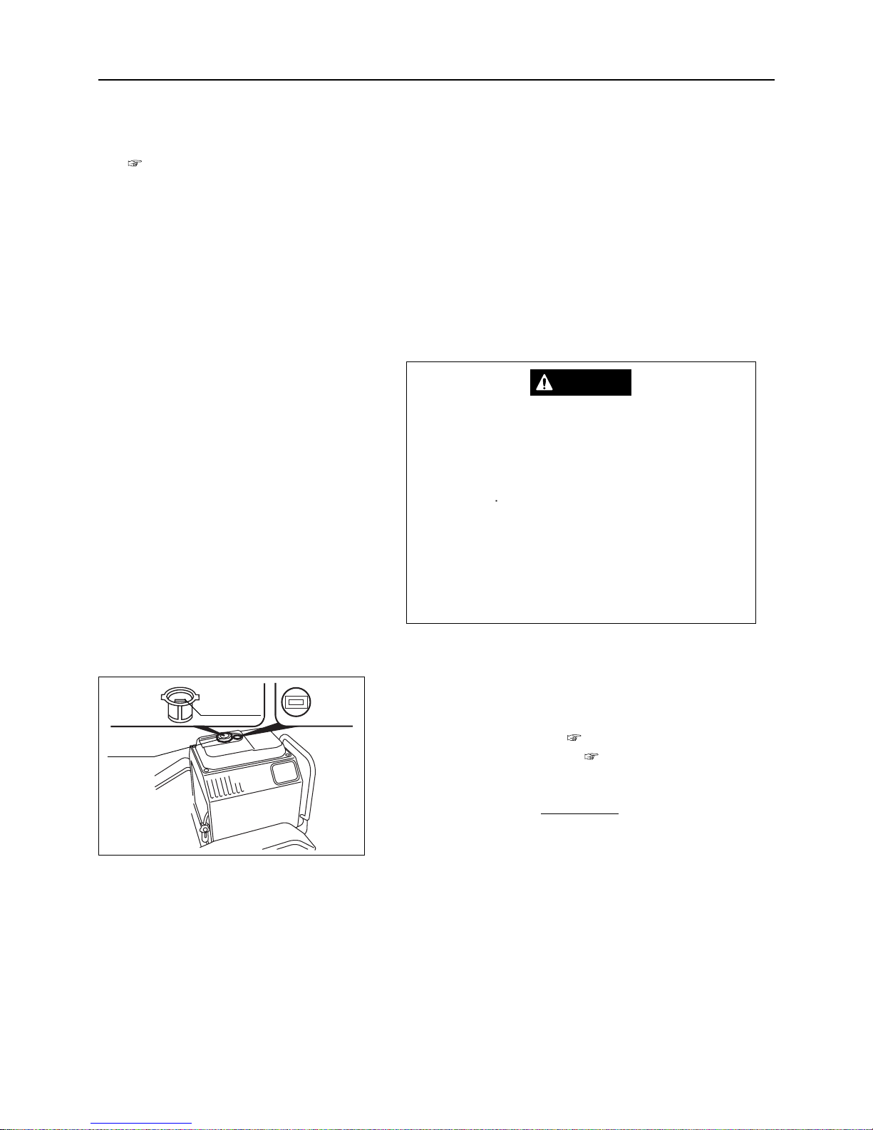
6.1 PREPARATIONS FOR OPERATION
6.1.1 Fuel Handling
•Petrol (gasoline) fuel is flammable. Never
refuel or service the fuel system while smoking or when near open flames or sparks.
•Never refuel the machine when the engine is
running
• After stopping engine, the engine becomes
hotter. Therefore fuel must be handled with
great care when refueling. Do not spill fuel
out of filler cap.
DANGER
1. Check the fuel gauge visually. If fuel is not reserved
enough, open the filler cap and pour fuel.
Fuel to be used : page 28
Fuel tank capacity : page 28
• When fuel gauge needle approaches empty
"E", refuel as soon as possible.
• When using the unit on slopes, refuel less
than the upper fuel limit for the fuel filter in
the lubrication port.
2. Close the filler cap firmly after refueling
NOTE
– 13 –
6
OPERATION
6. OPERATION
• Before reading this chapter, be sure to read "RULES FOR SAFE OPERATION AND WORK" in Chapter 3
(pages 5 to 8).
• Concerning the operation and control, be sure to follow the instructions given in this chapter. If you do not
have a complete understanding of the operating and control system or safety devices, never operate the
machine based on your own judgment.
Fuel
filter
Fuel
gauge
Upper limit
of oil level
Filler cap
Page 19
6
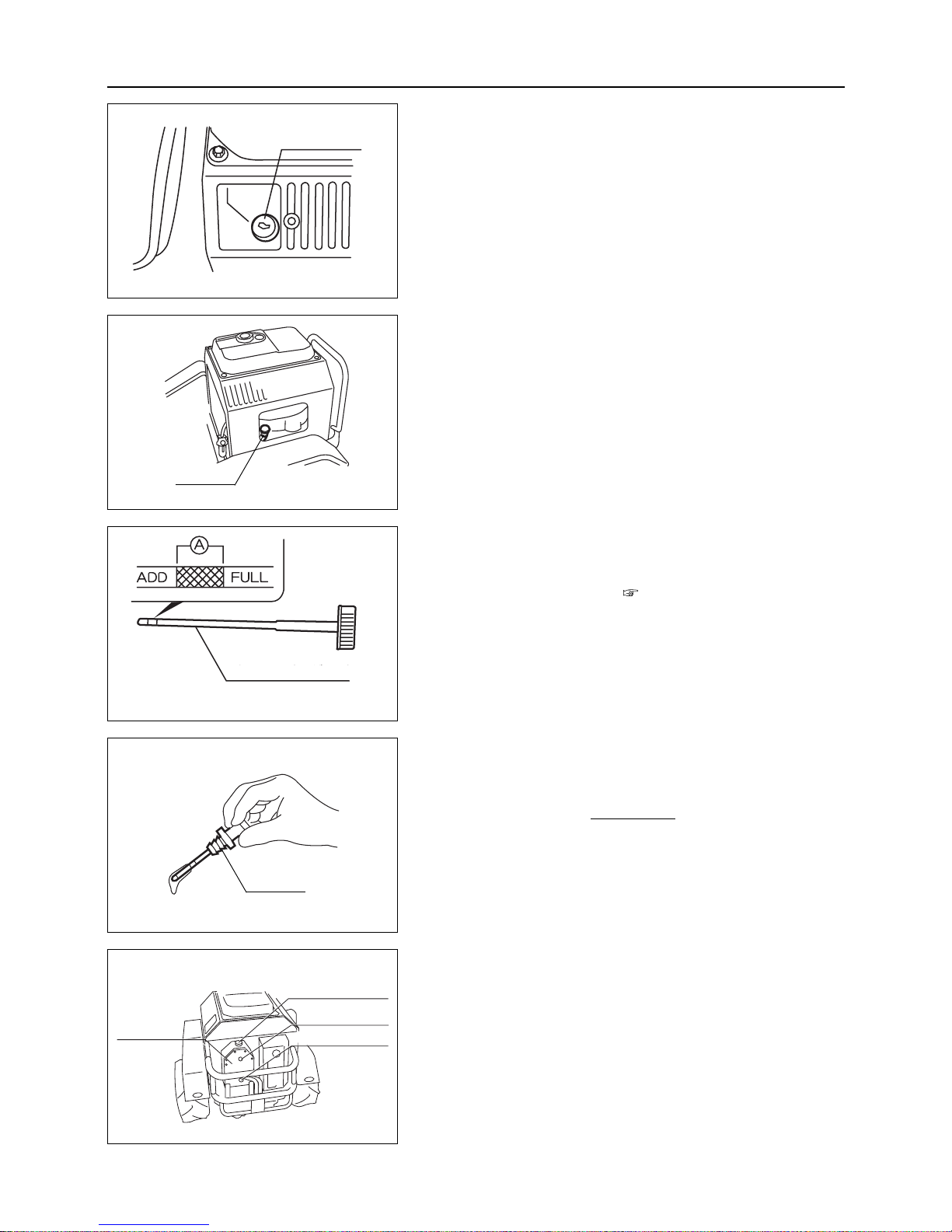
2. Check the amount of engine oil. If it is not in the range
A, supply engine oil from the refueling port.
Fuel to be used : page 28
Amount of engine oil :
In the case of CM 1801 :
Within the range A with the oil gauge tightened
In the case of CM1305 :
Between the upper and lower limits of the oil
gauge
(Do not exceed the upper limit.)
After checking and refueling are completed,
completely tighten the oil gauge with reliability.
NOTE
6.1.3 Inspection of the amount of HST oil and
replenishment
1. Remove the screw for the oil checking port of the HST
oil tank and check if oil comes out of the oil checking
port. (Check if oil has reached the oil checking port.)
Refueling cap
HST oil tank
Oil checking port
Drain bolt
– 14 –
OPERATION
6.1.2 Inspection & Refilling Engine Oil
1. Draw out the oil gauge. Clean the gauge with clean cloth.
Reinsert to measure oil level.
Oil gauge
<CM1305>
<CM1801>
Oil gauge
Oil gauge
Oil level gauge
<CM1305>
<CM1801>
Page 20
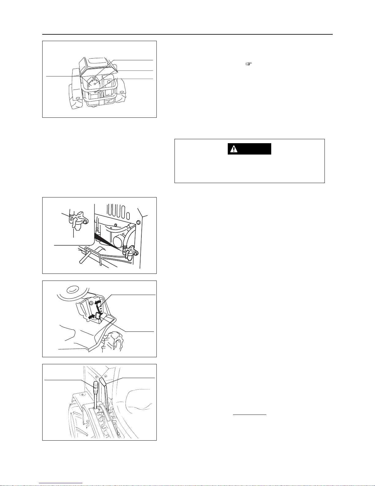
6.2 STARTING
When starting engine make sure that there is
enough ventilation to prevent poisoning from
the exhaust gas.
DANGER
1. Open the fuel cock.
2. Brake pedal should be locked.
(If not locked, depress the brake pedal and apply the parking
brake lock lever.)
3. Blade clutch lever should be in "OFF" position.
4. Blade height adjusting lever should be in "TRAVEL" position.
When the clutch of blade clutch lever is in "ON"
position, a safety switch is engaged and engine
will not start.
NOTE
– 15 –
6
OPERATION
2. When the amount of oil is insufficient, open the
refueling cap of the oil tank and supply HST oil.
Oil to be used: page 28
Amount of HST oil: 4.1 lit.
Brake pedal
Parking brake lock
lever
Blade height
adjusting lever
Blade clutch lever
Refueling cap
HST oil tank
Oil checking port
Drain bolt
Close
Open
Page 21
6
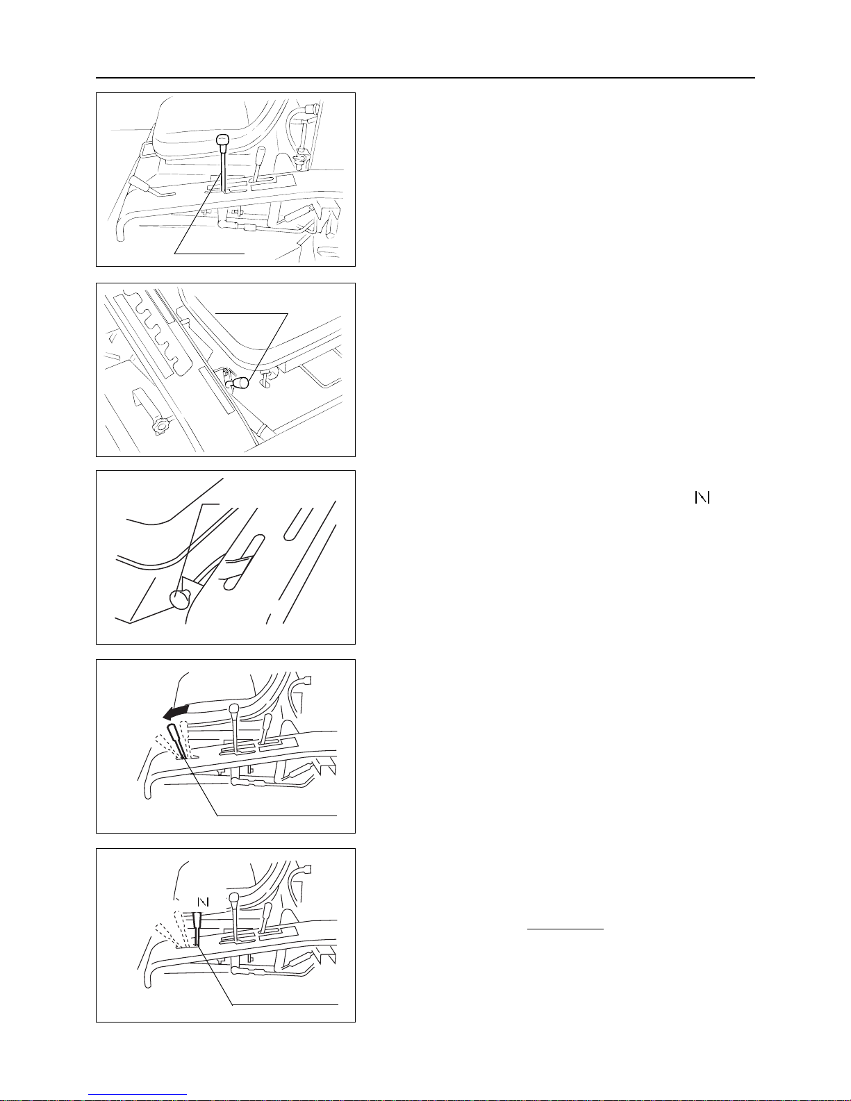
6. Aux. speed change lever should be in "Neutral" position.
In the case of CM 1801
7. Pull the choke lever and set it at the "Fully Close ( )" position.
– 16 –
OPERATION
5. HST lever should be in "Neutral" position.
Intermediate
speed
Low speed
Engine control lever
Engine control lever
8. Adjust the accelerator lever in the neutral position between
"High speed" and "Low speed."
In the case of CM 1305
7. Move the accelerator lever to the "High speed" position.
Even when the engine is warm, be sure to set
the accelerator lever at the "High speed" position when starting the engine.
NOTE
<CM1801>
<CM1305>
High speed
Fully Close
( )
HST lever
Aux. speed
change lever
Choke lever
Page 22
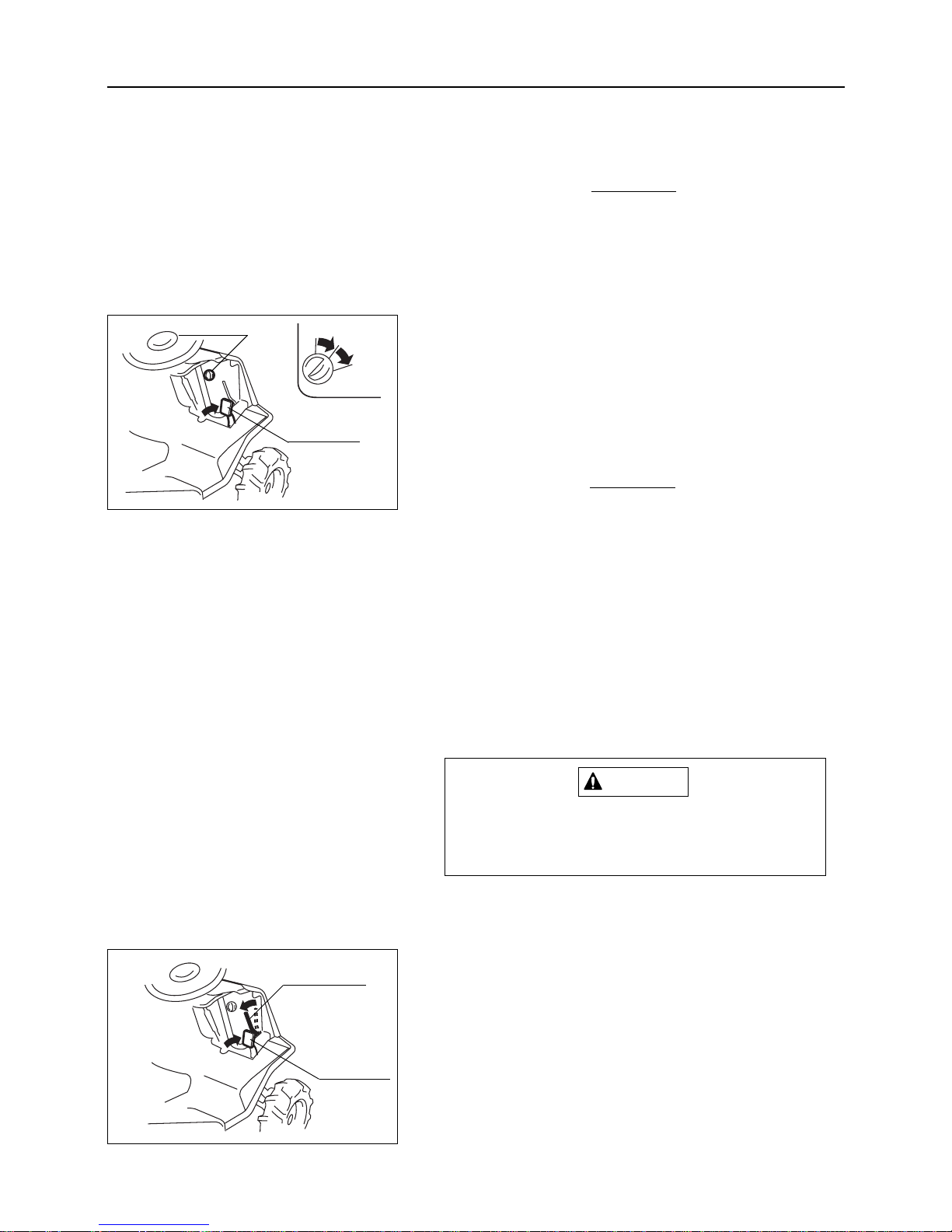
10. Remove main switch cap and put the engine key into main
switch.
11. Turn the key to the "START" position.
12. When the engine starts, release the key and it will spring
back to "ON" position.
• Do not run the start motor for a long time for
its long life. If the engine fails to start after
15-second try, wait about I minute for another try.
• When the engine fails to start, set the key
switch at "OFF" and then restart the engine.
Quick restarting may damage the starter
gear.
• When the operator does not sit on the seat,
a safety switch is engaged and engine will
not start .
During engine operation, never turn the key to
"START" position. Otherwise, the starter may
be damaged.
CAUTION
NOTE
13. Engage parking brake lock lever and push the brake pedal
into the full depressed position.
– 17 –
6
OPERATION
9. Release the parking brake lock lever and depress the brake
pedal fully.
When the brake pedal is not fully depressed, a
safety switch is engaged and engine will not
start.
NOTE
OFF
Main switch
START
ON
Brake pedal
Brake pedal
Parking brake
lock lever
Page 23
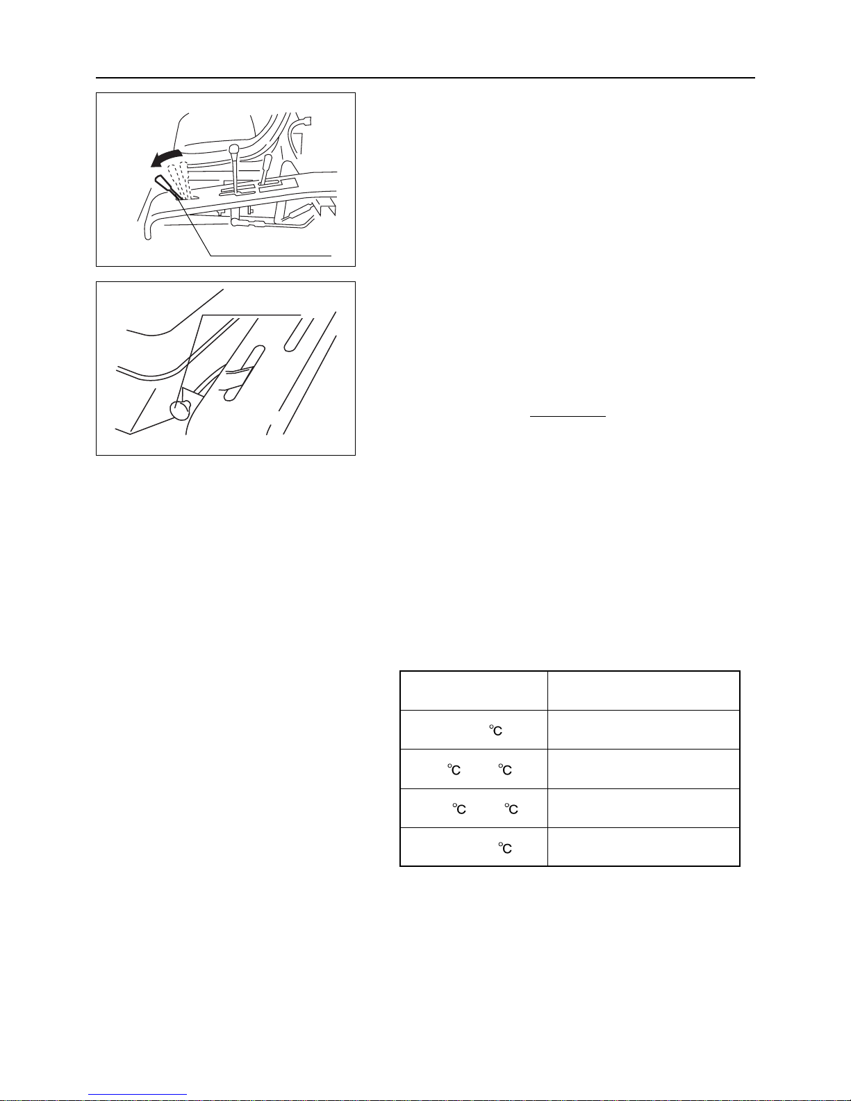
6
15. Return the choke lever to the "Fully Open" position.
(CM 1801)
16. Carry out warming-up without applying a load for three to
five minutes.
• Lack of warming-up engine may cause
seizure of engine.
• During the first 40 to 50 hours of new
machine use, do not use with excessive load
and avoid severe operations.
• In some areas where temperature is very
low, oil viscosity increases and normal operation may not be possible. Continue warming-up engine as indicated in the following
chart :
NOTE
– 18 –
OPERATION
14. Put the accelerator lever in the "Low speed" position.
Air temperature
Recommended warming-up time
Over 0 about 10 minutes
0 to -10 10 to 20 minutes
-10 to -20 20 to 30 minutes
Under -20
more than 30 minutes
Accelerator lever
Low
speed
Choke lever
Page 24
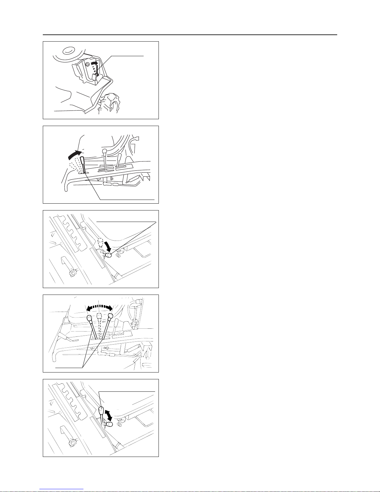
3. Put the accelerator lever to "High speed" position to increase
the engine speed.
4. Put the aux. speed change lever to "Low speed" position.
5. To accelerate, move the HST lever slowly.
Moving forward : Push the lever to the front.
Moving backward : Push the lever to the rear.
(WHEN CHANGING SPEEDS)
6. When conditions require speed changes, put the aux. speed
change lever to "High" or "Low" position.
(Speed shift is available when travelling)
– 19 –
6
OPERATION
6.3 OPERATION PROCEDURE
1. Check the area around the machine for safety.
2. Release the parking brake lock lever.
Parking brake
lock lever
Accelerator lever
High
speed
Low speed
Aux. speed change lever
HST lever
Forward
Reverse
Aux. speed change lever
Low speed
High speed
Page 25
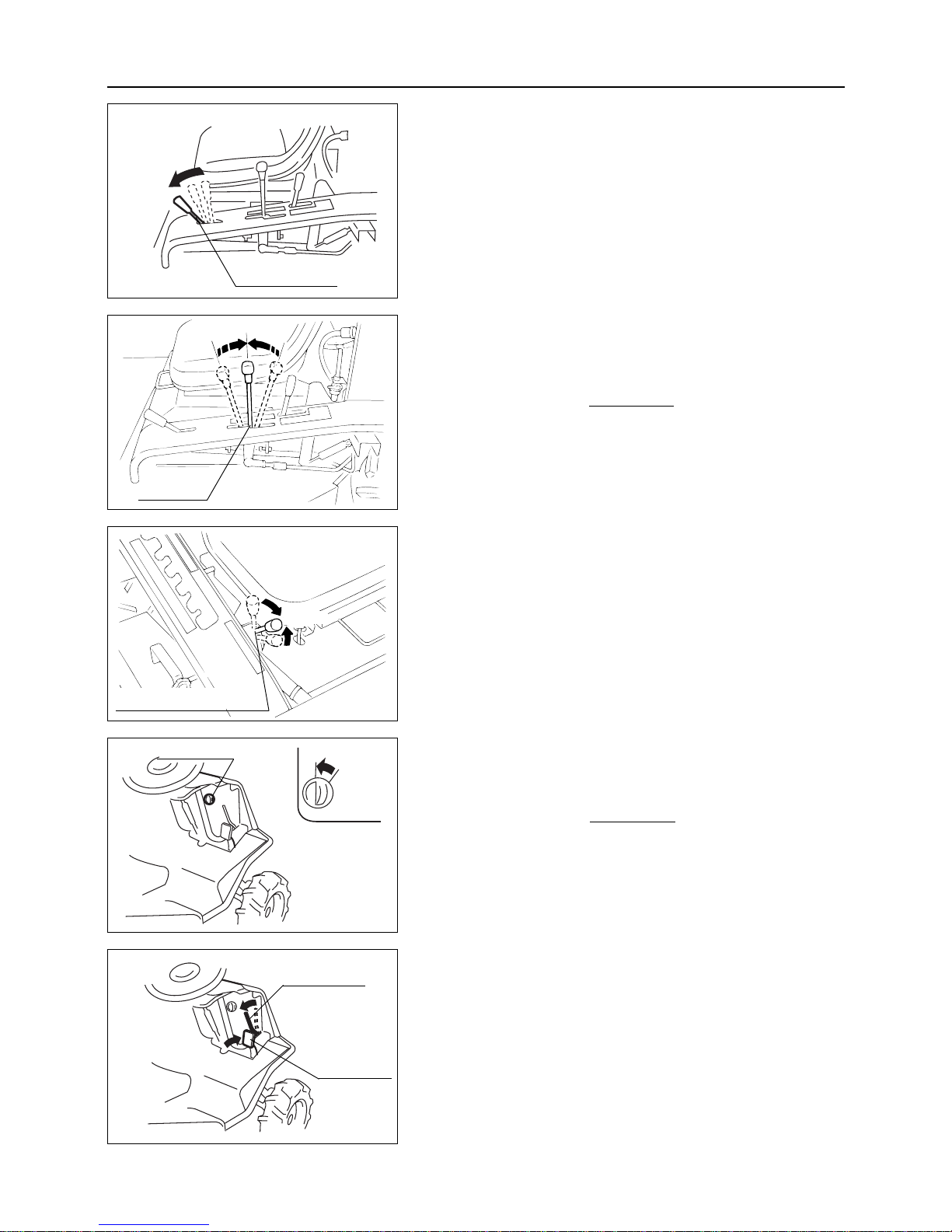
2. Return the HST lever to "Neutral" position and stop the
machine.
In case of emergency depress the brake pedal.
The HST lever automatically returns to
"Neutral" position and stops the machine.
NOTE
3. Return the aux. speed change lever to "Neutral" position from
High or Low position.
4. Turn the starter switch to the "OFF" position.
5. Remove the key.
Never leave the key in the "ON" position with
the engine. This may cause discharging of the
battery, because a current from the battery continues to flow to each circuit.
NOTE
6. Depress the brake pedal fully and apply the parking brake
lock lever to lock the brake pedal.
– 20 –
6
OPERATION
6.4 STOPPING PROCEDURE
1. Put the accelerator lever to "Low speed" position to decrease
engine revolution speed.
Neutral
OFF
Main switch
Brake pedal
Parking brake
lock lever
Accelerator lever
Low speed
Aux. speed change lever
HST lever
Neutral
Page 26
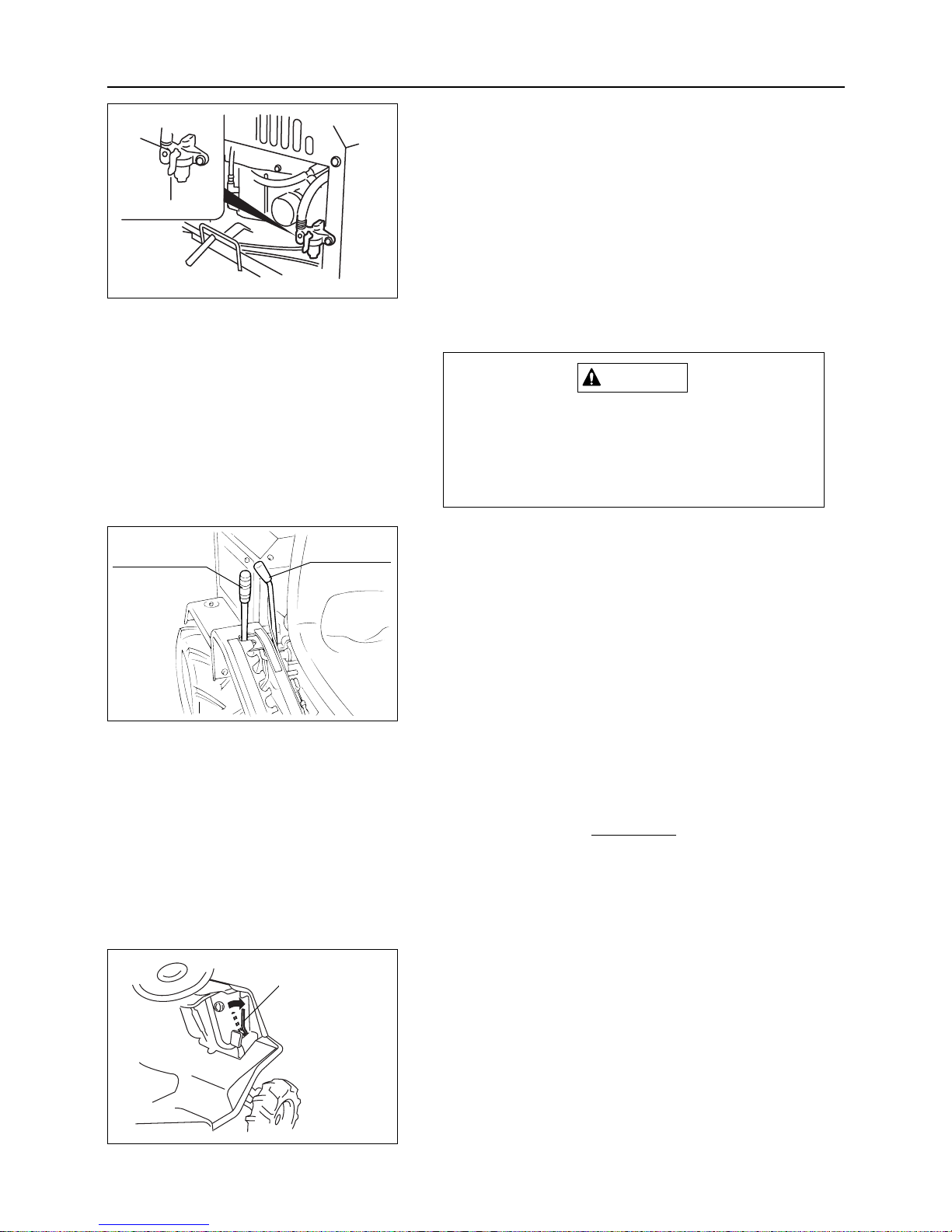
6.5 HOW TO PARK
Even when blade brake is in "OFF" position, the
blade may still be turning due to inertia. Do not
get off until the blade is completely stopped,
and always confirm that blade has stopped
turning before dismounting machine.
WARNING
1. Stop the machine under the procedures shown in item 6.4
STOPPING PROCEDURE.
2. Turn off engine and remove key.
3. Move the clutch of the blade clutch lever to the "OFF" position.
4.
Move the blade height adjusting lever to the "Transport" position.
6.6 HOW TO TRANSPORT THE MACHINE
IN CASE OF EMERGENCY
If the base unit does not operate with normal
control due to engine failure, etc., do not force
the machine to move. Transport the machine
with the following procedures.
NOTE
1. Move HST lever and aux. speed change lever to "Neutral"
position.
2. Move blade helght adjusting lever into "Transport" position.
3. Release the parking brake lock lever and then move base
machine.
– 21 –
6
OPERATION
7. Close the fuel cock.
Blade height
adjusting lever
Blade clutch
lever
Parking brake
lock lever
Open
Close
Page 27
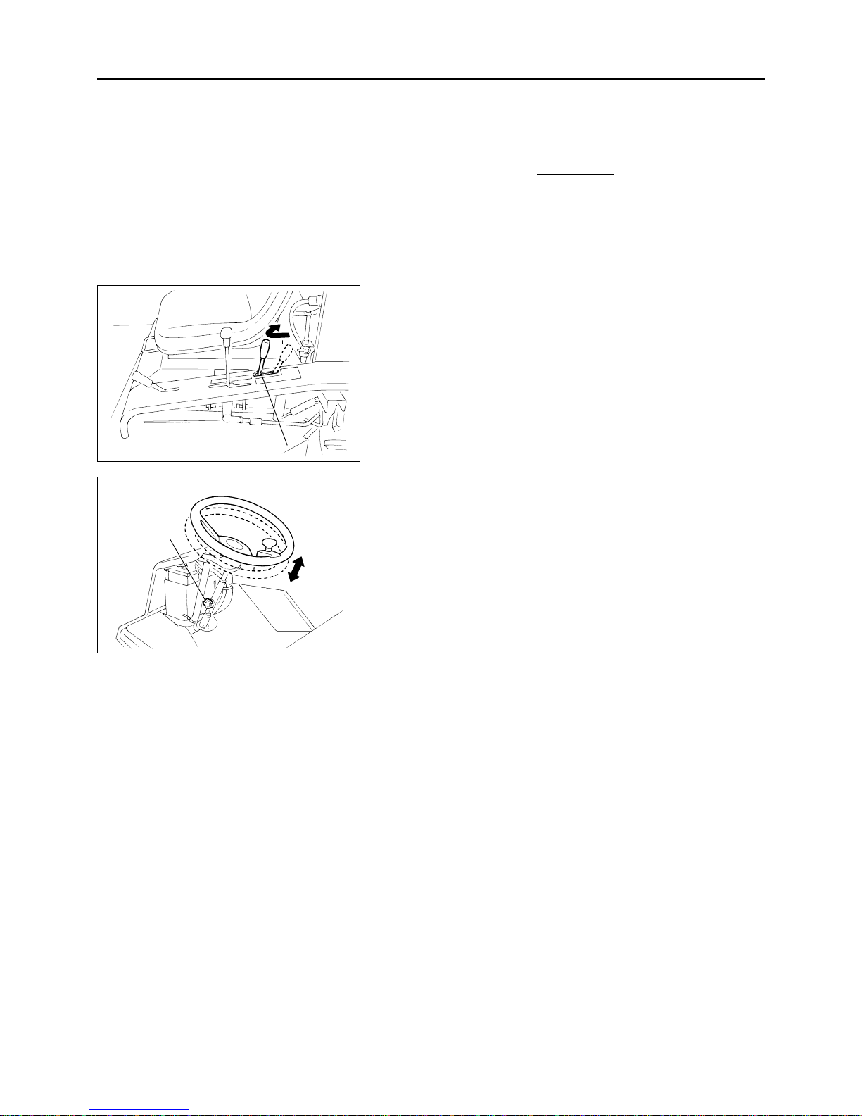
6
1. Move differential lock lever into "ON" position.
2. Move aux. speed change lever to "SLOW" speed side and
start to drive slowly.
3. After leaving steep slopes or soft ground areas, return differential lock lever to "OFF" position.
6.8 ADJUSTMENT OF STEERING WHEEL
HEIGHT
1. Release the adjusting knob and adjust the height of steering
handle by moving up or down.
2. Tighten the knob after adjusting height.
– 22 –
OPERATION
6.7 HOW TO AVOID REAR WHEEL
SLIPPAGE
Rear wheels slippage on steep slopes or soft
ground can be avoided by using differential lock
lever. During normal driving operation always
keep the differential lock lever in the "OFF"
position.
NOTE
Differential lock lever
Adjusting
knob
ON
Page 28
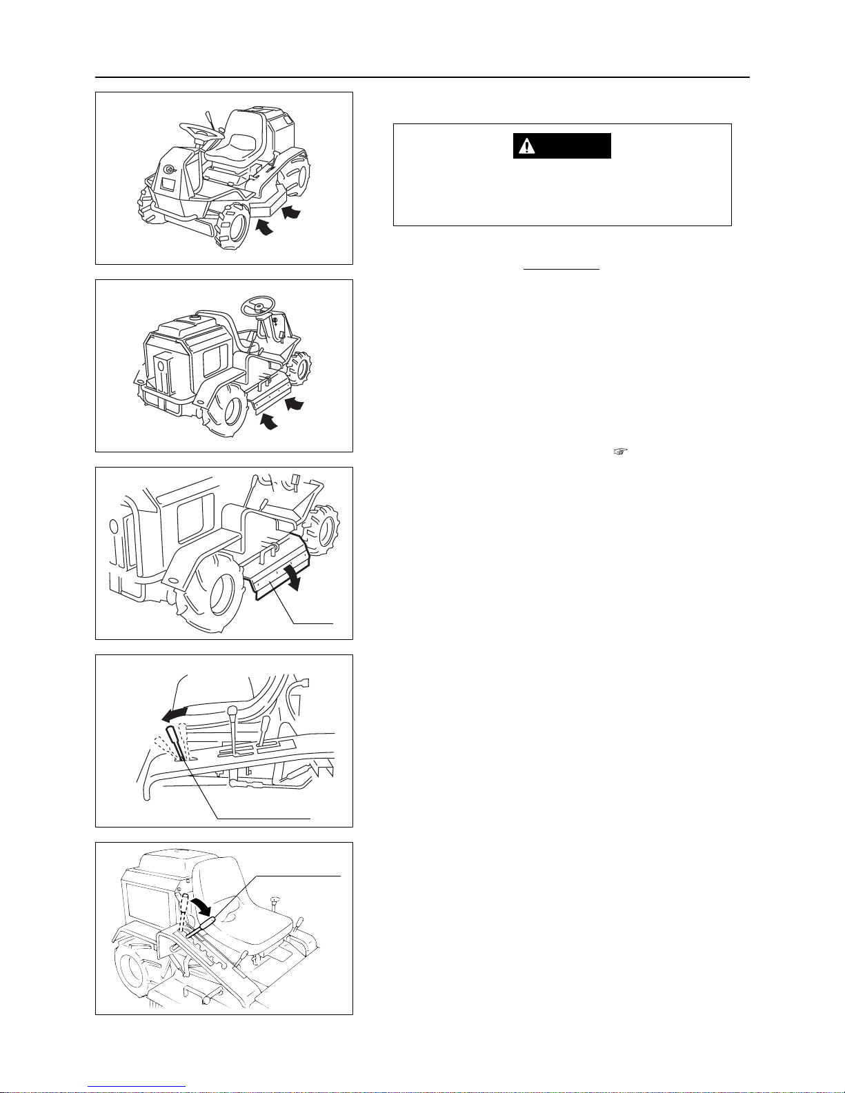
1. Confirm that the grass outlet cover is closed.
2. Stop the machine and move the accelerator lever to a position
between "High speed" and "Low speed".
3. Move blade height adjusting lever to the position ''5''.
– 23 –
6
OPERATION
6.9 HOW TO OPERATE BLADE
Never put legs beneath cutter blade covers.
The cutter blade rotates close to each cover
during operation.
• When using machine for the first time, select
flat ground and operate slowly so that each
cutting paths overlaps.
•
When cutting around obstacles, always position
trees, posts, and other obstacles on the left
side of the machine. (Make leftward turning.)
• Before carrying out work, be sure to read
"SAFETY PRECAUTIONS WHEN OPERATING" in Chapter 3 "RULES FOR SAFE
OPERATION AND WORK". ( Page 7)
NOTE
DANGER
Cover
Intermediate
speed
Accelerator lever
A
B
C
D
E
F
Blade height
adjusting lever
Page 29
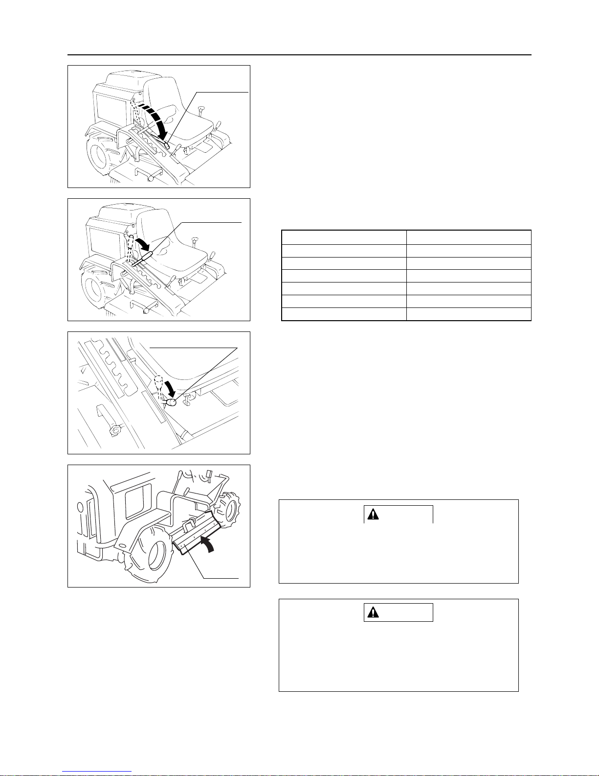
6
5. In accordance with your requirement adjust the height of the
cutter blade by controlling the blade height adjusting lever.
6. Move accelerator lever into High position to increase engine
speed.
7. Move aux. speed change lever into Low speed mode and start
driving with lower speed. (Adjust speed in accordance with
operating conditions.)
8.
When the work load is large (i.e. the amount of weeds is large),
carry out work by decreasing the speed or cut grass twice.
9. If grass outflow is not smooth, slightly open the right side of
the grass outlet cover.
Beware of stones or other objects which may
come of cutter blade area when opening the
grass outlet cover. Therefore, ensure the safety
completely.
Carry out the mowing operation in the forward
direction. Do not perform the operation in the
backward direction, because it makes grass
discharge poor and causes stones or other
objects to scatter.
CAUTION
CAUTION
– 24 –
OPERATION
4. Push blade clutch lever down slowly and push clutch into
"ON" position.
Blade height adjusting lever position
Blade height
Transportation for transportation
5 75 mm
4 60 mm
3 45 mm
2 30 mm
1 15 mm
Blade clutch
lever
Grass outlet cover
Low speed
Aux. speed change lever
A
B
C
D
E
F
Blade height
adjusting lever
Page 30
7
MAINTENANCE
– 25 –
7. MAINTENANCE
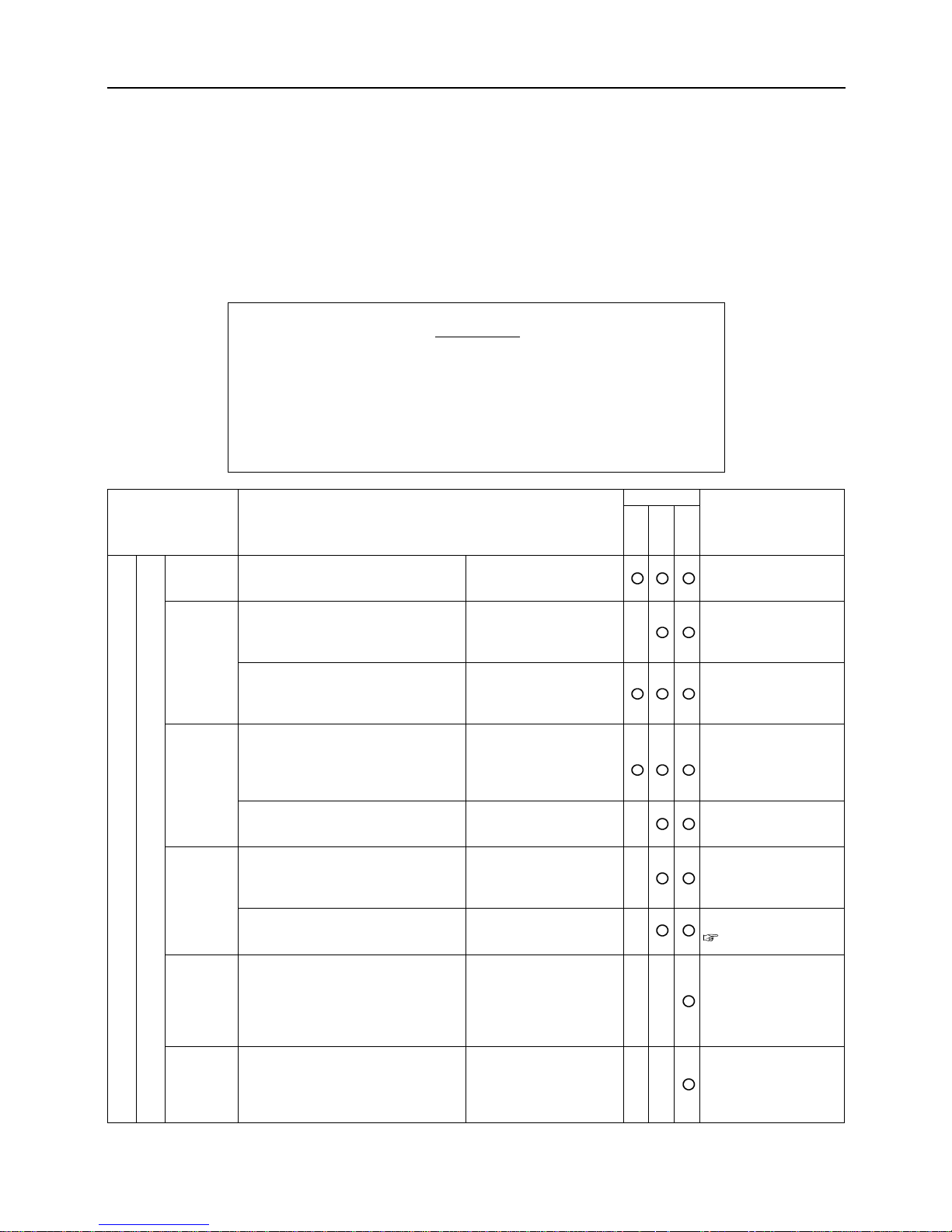
7.1 REGULAR INSPECTION CHART
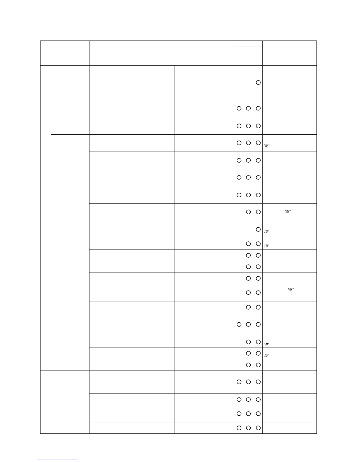
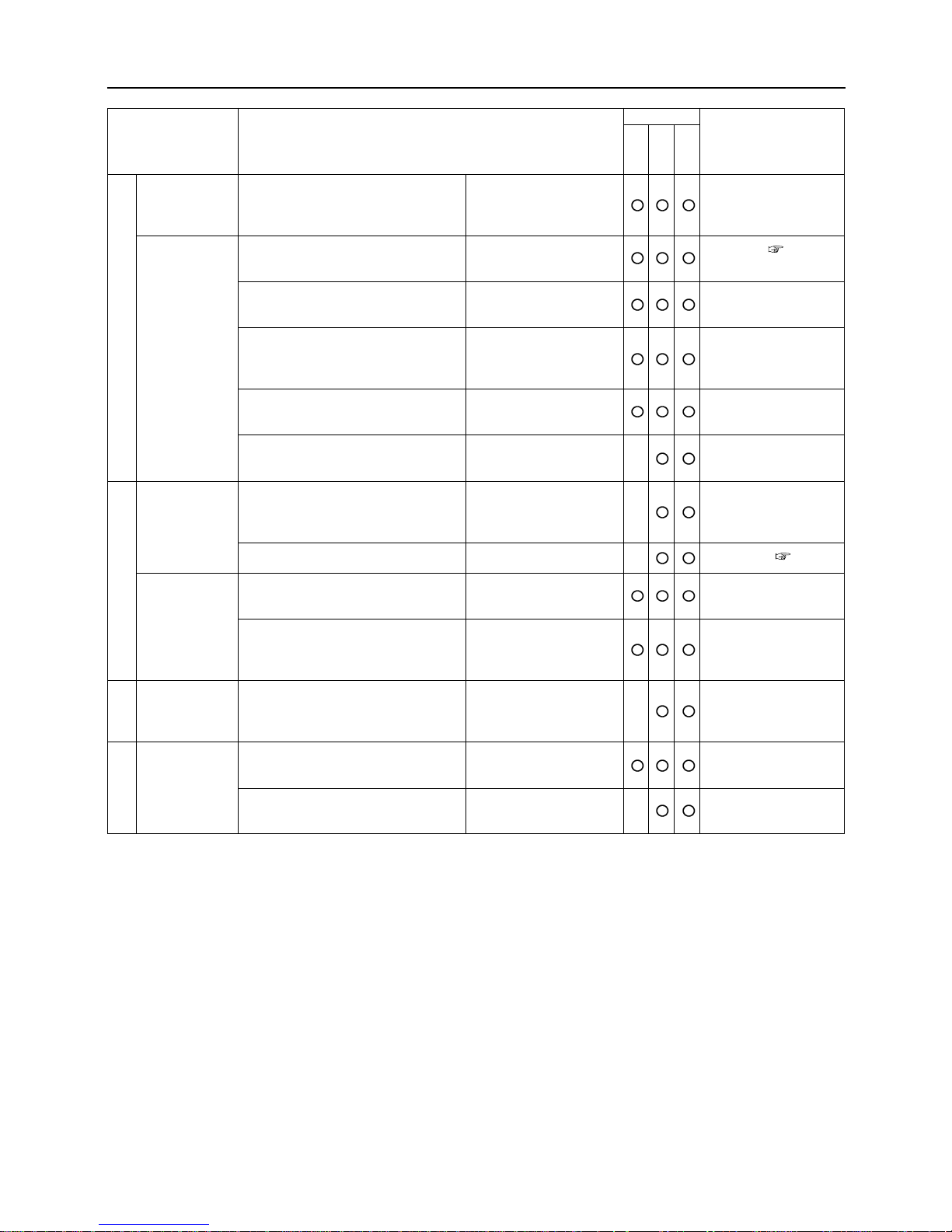
Proper inspection/maintenance will prevent accidents and breakdowns. To maintain the machine's normal
function and ensure daily safe operation, carry out the regular inspection according to the chart below.
The regular inspection consists of the yearly, monthly and daily pre-operation checks.
The chart below includes inspections which require technical
knowledge or specified tools and measuring instruments. As to
difficult inspections for the user, consult the dealer or one of our
service centers.
NOTE
Starting
Eng.speed
Exhaust
Air cleaner
Tightening
Valve
clearance
•
Check if engine starts smoothly and
makes abnormal noise.
• Check if engine speed is proper at
idling and unloaded max. speed.
Check for smooth operation.
• Accelerate engine and check for
axle lever drag, engine stall, and
knocking.
• After warming up engine, run
engine from idling to high speed
and check exhaust gas color and
noise.
• Check for gas leak from muffler,
exhaust pipe, etc.
• Check case for crack and
deformation, looseness at lid or
connecting pipe.
• Check element for dirt and
damage.
• Check cylinder head and manifold
retaining bolts/nuts for looseness.
*This check is not necessary if no gas
or water leak is found at these
areas.
• Check valve clearance.
*This check is not necessary if no valve-
derived abnormal noise is heard and
the engine operates smoothly.
Smooth start.
No abnormal noise.
Proper engine speed.
Smooth and continuous
engine operation.
No drag, engine stall, or
knocking.
Normal exhaust gas
color/noise.
No gas leak.
No crack or deformation
in case. No looseness at
lid and pipe.
No severe dirt.
No damage.
No looseness.
Proper clearance.
Request dealer for
inspection.
Cleaning/Replacement:
Page 37
Request dealer for
inspection.
Timing
Pre-op
Yearly
Monthly
Content RemarksItem
Body
Engine
Page 31
7
MAINTENANCE
– 26 –
Compressing
pressure
Engine
mount
Lubricating
system
Fuel system
V belt
Transmission
Speed change
lever
HST lever
Spark plug
Battery
Wiring
harness
• Check compression pressure.
*This check is dispensable if no
abnormality is found in engine
operation and exhaust condition at
idling and acceleration.
• Check engine base for crack and
deformation.
• Check bolts and nuts for looseness
or missing parts.
• Check oil amount and
contamination.
• Check head cover, oil pan, and
pipes for oil leak.
• Check fuel tank, injection pump,
hose, and pipes for fuel leak.
• Check fuel hose for damage and
deterioration.
• Check fuel filter element for dirt
and clogging.
• Check electrode for wear and
carbon deposit.
• Check electrolyte amount.
•
Check terminal for looseness and corrosion.
• Check connection for looseness.
• Check wiring harness for damage.
• Check appearance for crack,
damage, and dirt.
• Check belt tension.
•
Drive vehicle forward or rearward position, and check operating condition and
check for abnormal noise and overheat.
• Check oil amount in case.
• Check oil for contamination.
• Check case for oil leak.
• Check if the lever fits into each
speed position and moves smoothly
when driving.
•
Check connection for looseness or rattle.
• Check the movement of HST lever
when driving.
•
Check connection for looseness or rattle.
Proper pressure.
No crack or
deformation.
No looseness or
missing parts.
Proper amount.
No severe dirt.
No severe oil leak.
No fuel leak.
No damage or
deterioration.
No severe dirt.
No clogging.
No wear or carbon
deposit.
Proper amount.
No looseness or severe corrosion.
No looseness.
No damage.
No crack, damage, or
grease deposit.
Proper tension.
Normal operation.
No abnormal noise or
overheat.
Proper amount.
No severe contamination.
No oil leak.
Proper fitness to each
position and proper
movement of the lever.
No looseness or rattle.
Proper and smooth
movement.
No looseness or rattle.
Request dealer for
inspection.
Inspection/Replacement:
Pages 30 and 31
Cleaning: Page 39
Inspection/Cleaning:
Pages 38 and 39
Inspection/Refilling:
Page 35
Inspection: Page 41
Inspection/Replacement:
Pages 31 and 32
Inspection/Replacement:
Pages 31 and 32
Timing
Pre-op
Yearly
Monthly
Content RemarksItem
BodyElectrical
EnginePower trainSpeed adjustment
Page 32
7
MAINTENANCE
– 27 –
Steering wheel
Tire, wheel
Brake
Rod, link, and
wires
Body, cover
Headlamp
•
Drive vehicle and turn steering
wheel right and left for firm
steering operation.
• Check tire pressure and groove
depth.
• Check tire/wheel for crack,
damage, and partial wear.
• Check tire groove for foreign
objects such as metal fragments
and gravel.
• Check wheel bolt/hub nut for
looseness or missing parts.
• Check wheel bearing for looseness,
abnormal noise and overheat.
• Drive vehicle and operate brake
pedal and parking brake. Check the
operation.
• Check brake pedal free play.
• Check rod/link/wires for damage
and looseness at connection.
• Repeatedly operate brake and
check connection for looseness and
missing split pins.
• Check body and cover for crack,
deformation, and loose/missing
bolt/nut.
• Operate light switch and check
headlamp operation.
• Check lamp for lens damage or
water intrusion.
Proper steering.
Within criterion.
No crack, damage, or
partial wear.
No foreign object.
No looseness or missing
parts.
No looseness, abnormal
noise or overheating.
Proper brake etfect.
Proper amount.
No damage or looseness.
No looseness at
connection or missing
split pins.
No crack, deformation, or
loose/missing bolt/nut.
Normal operation.
No damage or water
intrusion.
Inspection: Page 42
Adjustment: Page 42
Timing
Pre-op
Yearly
Monthly
Content RemarksItem
Driving systemBrakeBodyLamp system
Page 33

7
MAINTENANCE
– 28 –
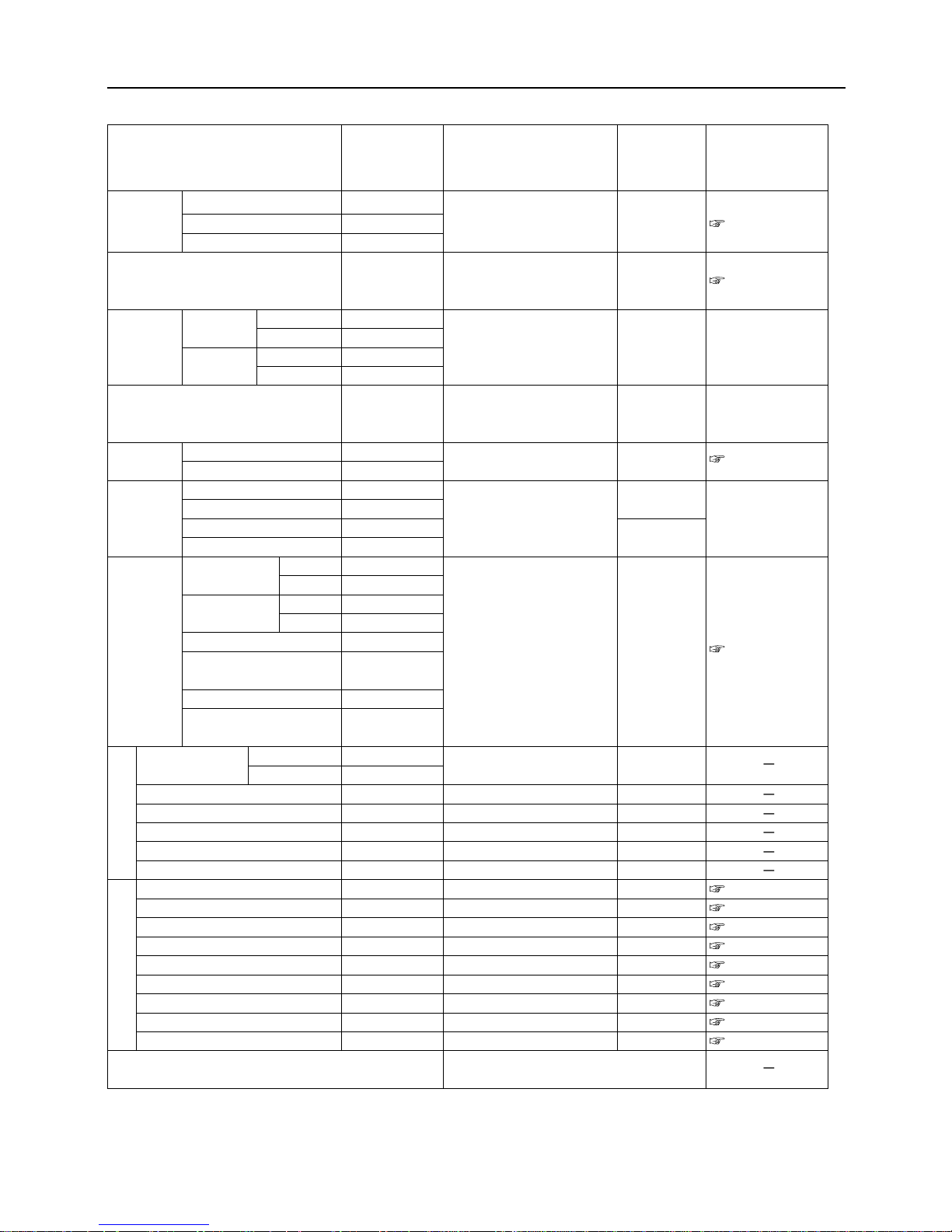
7.2 OIL/GREASE/LUBRICANT/FLUID LIST
Fuel
Engine oil
Transmission oil
HST oil
Each area to be lubricated
Each area to be greased
Battery fluid
*1) 1.5 lit. at the time of oil filter replacement (CM1801)
As necessary.
Add : Check daily and add as
necessary.
Replace :
1st : 8 operating hours
2nd or later : every 50
operating hours (Every
week)
Replace :
1st : 50 operating hours
2nd or later : every 500
operating hours
Every six months.
* No need for lubrication for
the first 6 months after
purchase
Every six months.
* No need for greasing for
the first 6 months after
purchase
Check every month and add
as necessary.
Gasoline
API class : SD or higher, or
SAE class: 10W-30
Gear oil
API class GL4 or 5
SAE class #80
(SAE class 20W-50 engine oil MOBIL SHC629)
Gear oil
API class GL4 or 5
SAE class #80
Chassis grease
Distilled water
11.0
1.4
1.2
4.1
Page 13
Page 30
Page 31
Page 32
Page 34
Page 33
Page 35
Timing Recommendation
Amount
Reference
page
Item
Page 34
7
MAINTENANCE
– 29 –
7.3 CONSUMABLES (SERVICE PARTS) LIST
Air cleaner
Fuel cock
V-belt
Brake lining
Battery
Tire
Fuel pipe
Wire
Throttle wire
Choke wire (CM1801)
Blade clutch wire
Brake wire
Differential lock wire
Blade brake wire
Stay
Blade
Cup square neck bolt
Collar
Cap
SW
Castle nut
Split pin
Brake lever
Parts, other than the above, which seem to require
replacement as a result of inspection
Consult the dealer (or one of our service
centers).
CM1801
CM1305
Rotaries
Form element (CM1801)
Paper element (CM1801)
Element (CM1305)
Running
CM1801
CM1305
Rotary
CM1801
CM1305
CM1801
CM1305
Front (R)
Front (L)
Rear (R)
Rear (L)
From the front CM1801
of tank to joint CM1305
From the rear CM1801
of tank to joint CM1305
From joint to cock (CM1801)
From cock to filter
(CM1801)
From joint to cock (
CM1305
)
From cock to filter
(CM1305)
11013-7001
11013-7002
53040001300
53060329000
08521300033
08521300036
08521500069
08521500066
73014007000
37053901000
34070501000
53042201000
53042206000
53042301000
53042302000
53060332000
53060333000
53060331000
53080323000
53060333000
53050325100
53050331000
53080325000
53090105000
53040209000
53090106000
53062431000
36103014000
36083229000
53064311000
53044205000
53044202000
53044203000
53044204000
53044204100
A3600101202
A3110101203
05200132025
53064301000
Check every 50 operating
hours (every week) and
replace if malfunctioning.
Check every 200 operating
hours (every month) and
replace if malfunctionin .
Replace if malfunctioning.
Replace if malfunctioning.
Replace if malfunctioning.
Replace if malfunctioning.
Every three years or when a
malfunction is found.
Replace if malfunctioning.
Replace if malfunctioning.
Replace if malfunctioning.
Replace if malfunctioning.
Replace if malfunctioning.
Replace if malfunctioning.
Replace if malfunctioning.
Replace if malfunctioning.
Replace if malfunctioning.
Replace if malfunctioning.
Replace if malfunctioning.
Replace if malfunctioning.
Replace if malfunctioning.
Replace if malfunctioning.
Replace if malfunctioning.
1
1
1
1 set (The
entire set is
replaced.
1
2 for the front
2 for the rear
2
1
1
1
1
1
1
1
2
2
2
2
2
2
2
1
Pages 37 and 38
Page 39
Request dealer for
replacement.
Request dealer for
replacement.
Page 36
Request dealer for
replacement.
Page 43
Page 43
Page 43
Page 43
Page 43
Page 43
Page 43
Page 43
Page 43
Page 43
Part No. Replacement timing Quantity Reference pageItem
Page 35
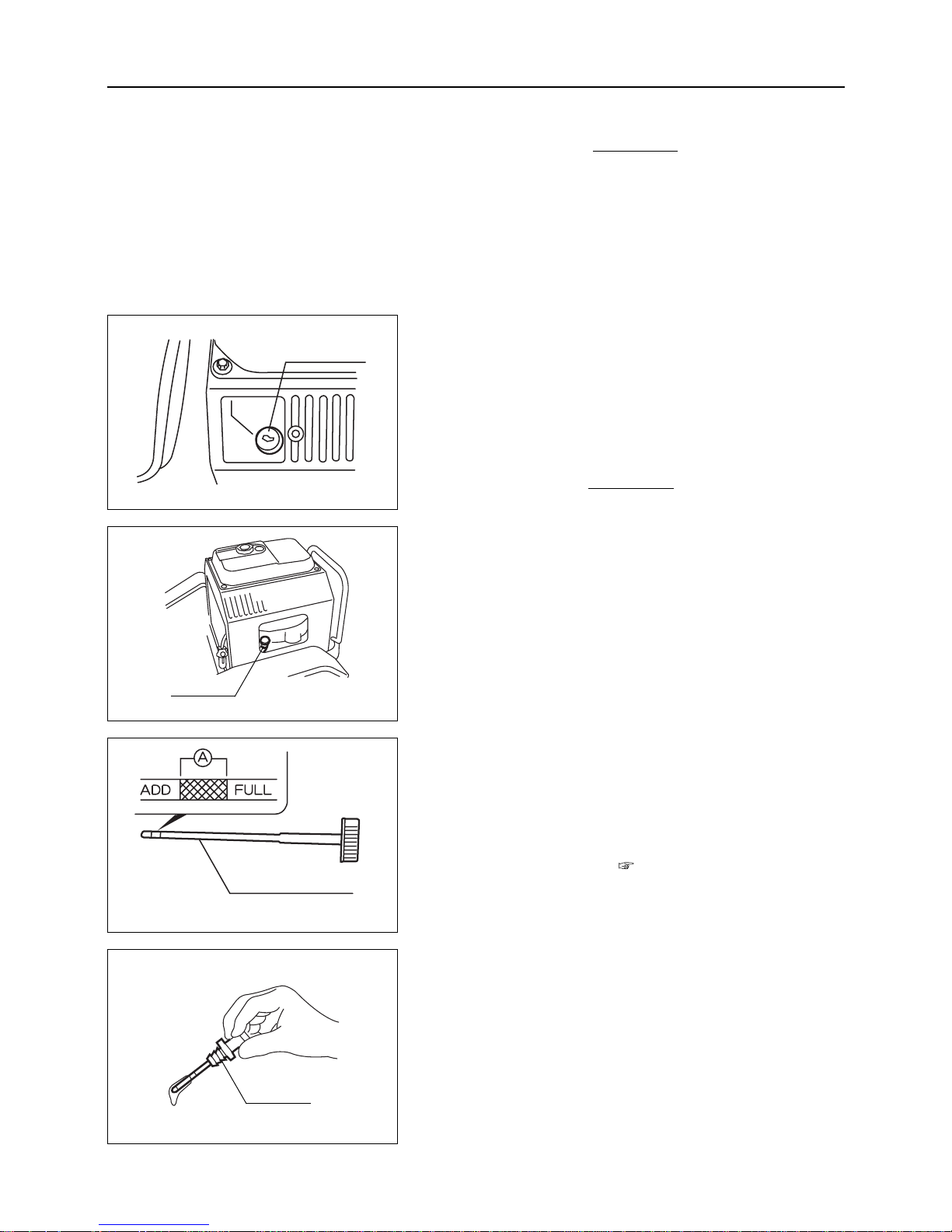
7.4.1 Engine Oil
Inspection/Refilling
1. Park machine on a horizontal surface.
2. Remove oil gauge.
Inspect engine oil quantity either before starting
engine or more than 5 minutes after stopping
engine. Immediately after stopping engine, oil
still remains in engine parts and correct oil
quantity inspection is impossible.
NOTE
3. Check the amount of engine oil visually. If it is not in the
range A, supply engine oil.
4. Visually check the engine oil for dirt. When the engine
oil is very dirty, replace it.
Fuel to be used : page 28
Amount of engine oil :
In the case of CM1801
Within the range A with the oil gauge tightened
In the case of CM1305 :
Between the upper and lower limits of the oil
gauge
(Do not exceed the upper limit.)
5. Reinsert oll gauge.
– 30 –
7
MAINTENANCE
7.4 LUBRICATION
• Insufficient or improper lubrication not only
causes the machine to fail to achieve
smooth turning but also causes it to break
down, shortening the life of the machine.
Therefore, fill the machine with the right
amount of designated good quality oil on a
regular basis.
• Always shut off the engine before inspection
or servicing.
NOTE
< CM1305 >
< CM1305 >
< CM1801 >
< CM1801 >
Oil gauge
Oil gauge
Oil level gauge
Oil gauge
Page 36
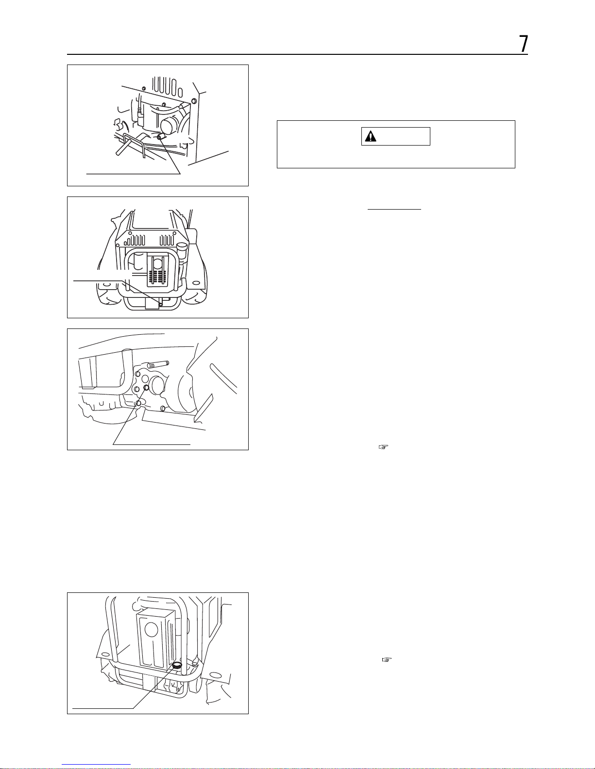
3. Replace oil drain plug.
4. Remove oil gauge and pour the designated oil from the
lubrication port.
7.4.2 Transmission Oil
Inspection
1. Park machine on horizontal surface.
2. Remove the oil level check bolt and check if oil comes
out from the bolthole. (Check if oil has reached the check
bolthole.)
Amount of oil : page 28
(Up to a point where oil reaches the oil level
check bolthole)
To add oil
1. Remove lubricating plug.
2. Pour the designated oil from the lubrication port.
Oil to be used : page 28
– 31 –
MAINTENANCE
Replacement
1. Prepare a suitable container to collect drained oil.
2. Remove oil drain plug and drain oil from crankcase.
Hot oil can cause burns.
Properly dispose of drained oil.
NOTE
CAUTION
Oil level check bolt
Lubricating plug
Oil drain plug
Oil discharge port
Page 37
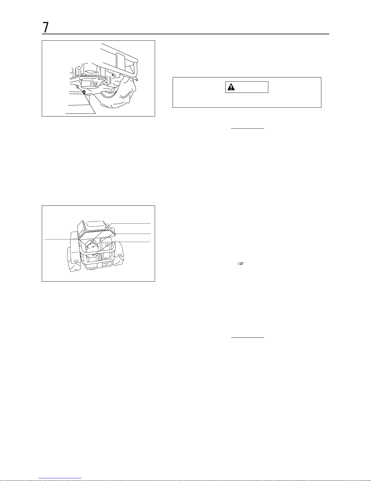
7.4.3 HST Oil
Inspection/Refilling
1. Park the machine in a horizontal place.
2.
Check the amount of oil. When it is insufficient, supply oil (Page 14)
Oil to be used : page 28
Amount of HST oil: 4.1 lit.
Replacement
1. Prepare a suitable container to collect drained oil.
2. Remove the drain plug and drain oil.
Properly dispose of drained oil.
3. Replace the drain plug.
4. Open the refueling cap and put in a proper amount
of designated oil.
NOTE
– 32 –
MAINTENANCE
Replacement
1. Prepare an appropriate container to collect oil.
2. Remove drain plug and drain oil into container.
Hot oil can cause burns.
CAUTION
Properly dispose of drained oil.
3. Replace drain plug.
4. Open the oil plug and pour the designated oil.
NOTE
Drain plug
Refueling cap
HST oil tank
Oil checking port
Drain plug
Page 38
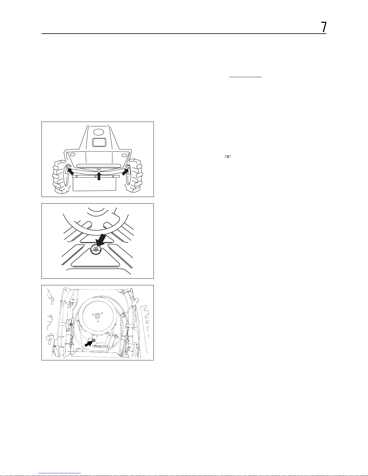
7.5.1 Lubrication
Lubricate the points as shown in the figure.
Oil to be used : page 28
1. King pin. Pin for front axle shaft
2. Brake link section
3. Fulcrum of rotary stopper
– 33 –
MAINTENANCE
7.5 LUBRICATION AND GREASING
Insufficient or improper greasing can cause
seizure or rust, making it difficult to achieve
smooth turning and operation.
NOTE
1.
2.
3.
Page 39
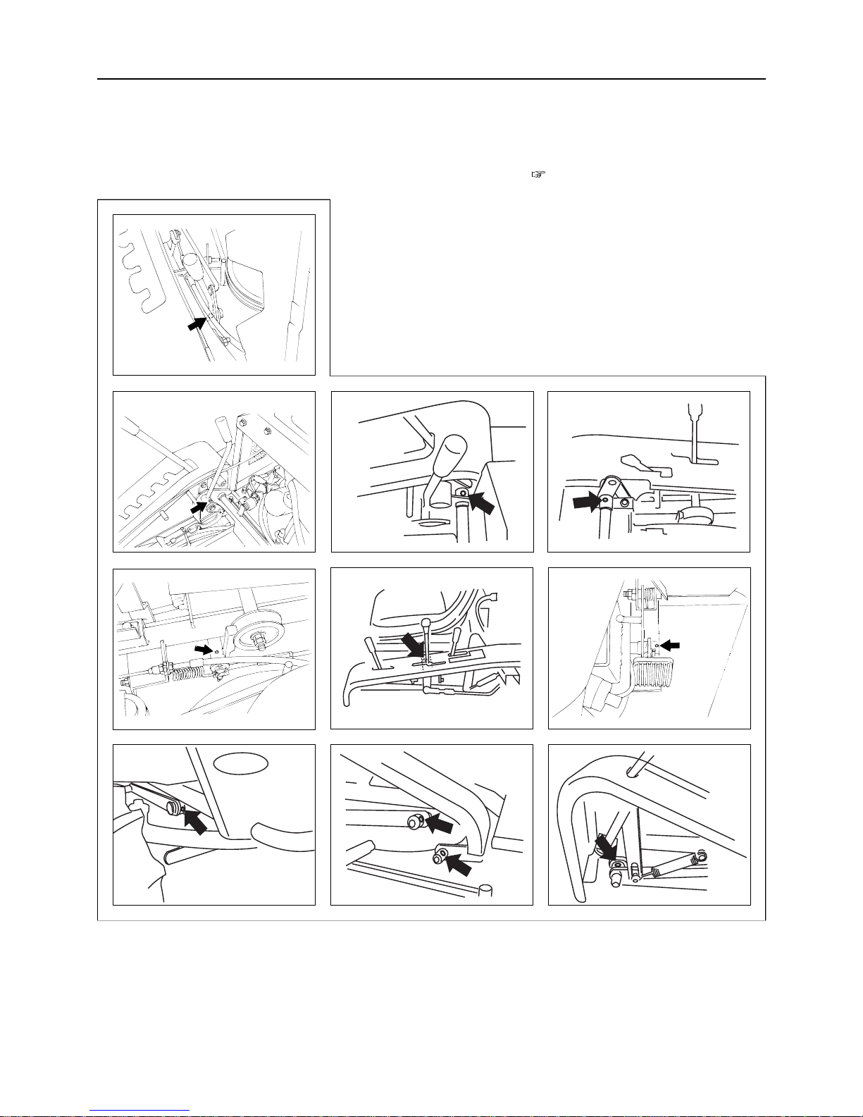
7.5.2 Greasing
Grease the points as shown in the figure.
Oil to be used : page 28
4. Fulcrum of aux. speed change lever
5. Blade clutch lever fulcrum
6.&7. Fulcrum of cutter height adjusting lever link
8. Brake arm fulcrum
9. HST lever fulcrum
10. Brake pedal fulcrum
11.12.13.&14. Blade stay fulcrum
(11.12.13.&14.are also provided on the other side.)
7
– 34 –
MAINTENANCE
4.
10.
14.
5.
11.
6.
9.
13.
7.
8
12
Page 40
• Battery fluid sulfuric contains acid which
may cause burns. Avoid fluid contact with
skin or clothes, immediately remove affected
clothes and clean the affected skin.
• Before checking or removing the battery,
always stop engine and turn "OFF" the main
switch.
CAUTION
– 35 –
7
MAINTENANCE
7.6 POURING BATTERY FLUID
7.6.1 Battery Fluid
The gas generafed from the battery is flammable.
Keep open flames away from battery. Open
flames may cause battery explosion.
DANGER
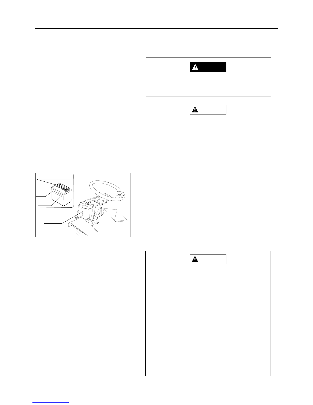
Inspection/Replenishment
1. Park machine on horizontal surface.
2. Visually check the battery fluid quantity and add fluid if
necessary by removing front cover and battery cap.
Proper battery fluid level
: Between (upper and
lower) reference lines
Battery fluid : Distilled water
Charging
• Always remove the battery from the vehicle
before charging. Charging the battery on
vehicle may cause damage to electrical
parts or wiring harnesses.
• Connect cables to correct terminals of the
battery. Connecting to wrong terminal will
immediately blow the fuse and render the
battery not rechargeable.
•
When disconnecting cables from the battery,
disconnect plus terminal first. If you reverse
the order, the battery may be shorted if a tool
touches any conductive part of the battery.
• When reinstalling the removed battery, correctly connect the plus and minus cables
and properly route and secure the cables
with the tightening bolt so that they will not
cause a short circuit with the other parts of
the vehicle body.
CAUTION
Battery cap
Battery
Upper
limit
Lower
limit
Page 41
– 36 –
7
MAINTENANCE
Quick charging is a method to partially
recharge a battery in a short time with a large
amount of current. This method should be used
only in emergencies. After quick charging,
always fully recharge the battery according to
the proper procedure as soon as possible.
Quick charging will extremely shorten battery
life.
NOTE
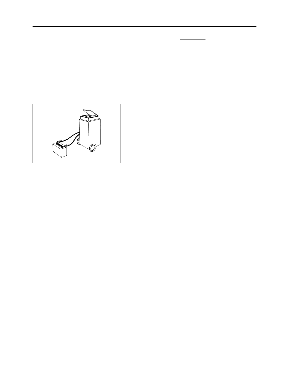
1. Remove the battery.
2. Connect a battery charger with the battery matching the
polarities. (Follow the instructions in the battery charger
operation manual.)
Page 42
Cleaning
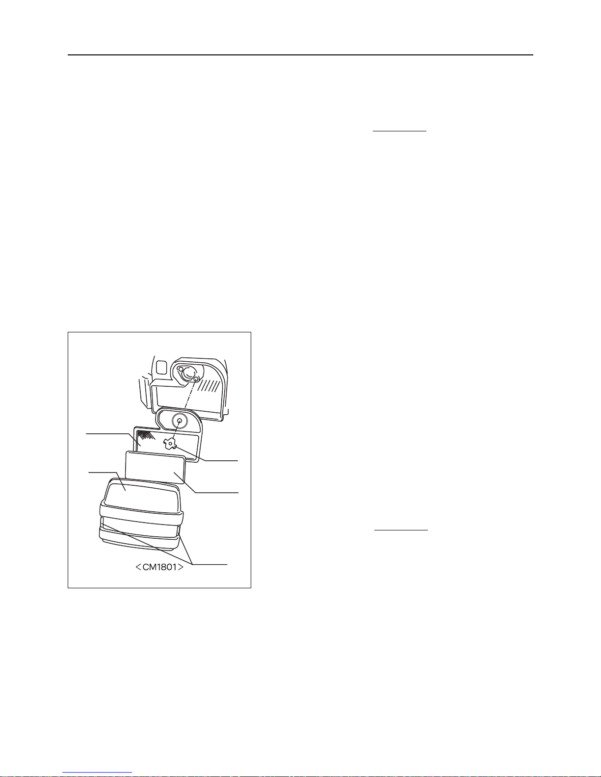
In the case of CM1801:
1. Remove the hooks on both sides of the air cleaner cover
and remove the cover.
2. Remove the wing bolt and remove the form element and
paper element. Clean the form element in a tank containing a detergent and water. Then, dry the form element by
applying compressed air to it or shaking it. After cleaning, allow clean engine oil to soak into the form element
and squeeze excess oil. Then, wrap the form element in a
clean cloth and dry it as much as possible by squeezing.
3. Install the form element and paper element. Then, install
them on the main body with the wing bolt.
If the air cleaner is noticeably dirty or damaged,
replace it.
4. Install the cover on the main body.
NOTE
Replacing
Inspect air cleaner every 50 hours (every week) and replace if
necessary.
– 37 –
7
MAINTENANCE
7.7 CLEANING
7.7.1 Air Cleaner Element
• Make sure to clean the air cleaner element
on a regular basis (every 50 hour operation).
A severely contaminated air cleaner element
will badly affect engine startability, power
and life.
• Since air cleaner is dry type, do not use oil.
Also never use compressed air for cleaning
and drying.
• Handle with care for not breaking cleaner or
deform it.
NOTE
Paper
element
Cover
Form
element
Wing bolt
Hook
< CM1801 >
Page 43
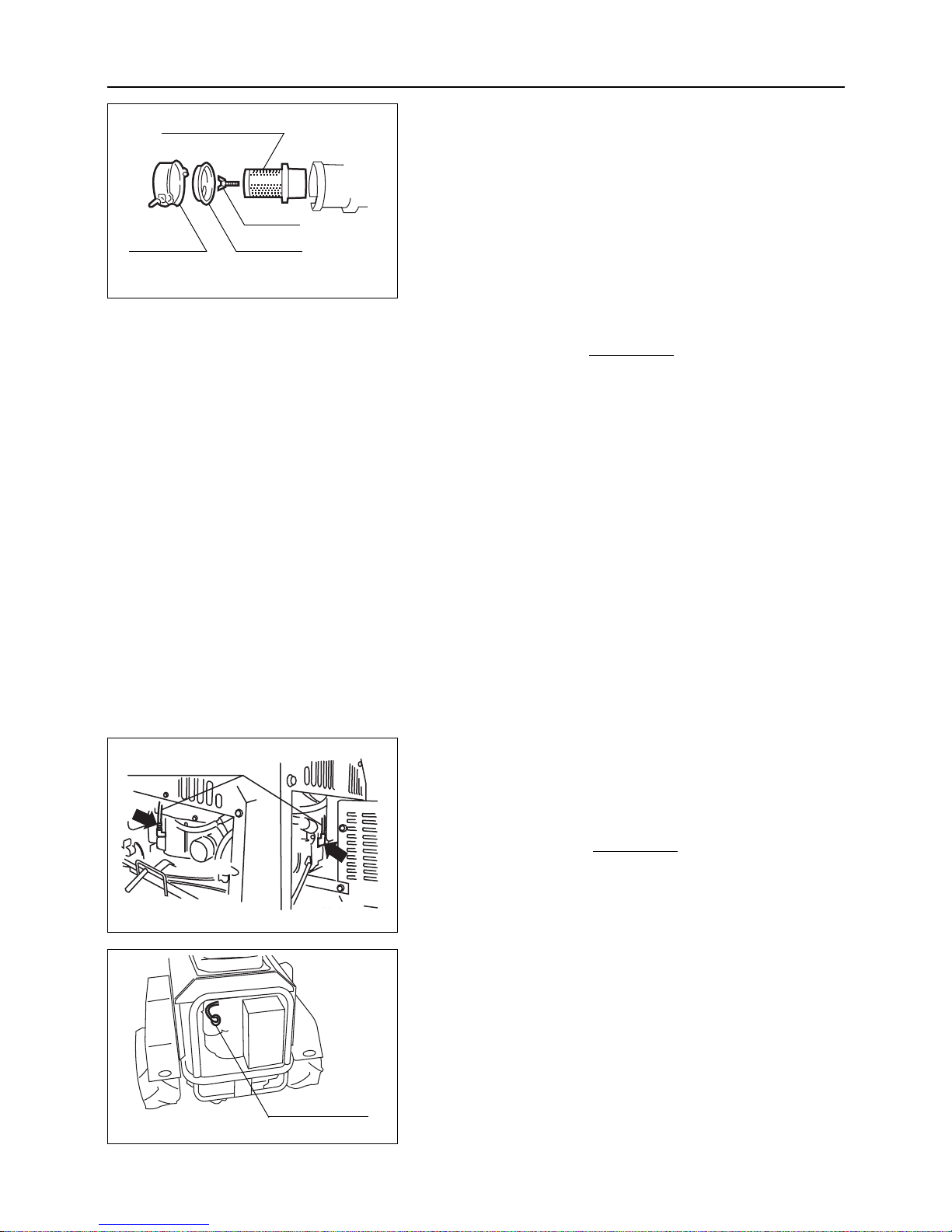
7.7.2 Spark Plug
Inspection
1. Remove the spark plug cap.
Do not pull on the cable when removing the
spark plug cap. Always hold the cap body.
NOTE
– 38 –
7
MAINTENANCE
In the case of CM1305:
1.
Remove the air cleaner cover.
2. Remove the wing bolt.
3. Remove the dust cover and air cleaner element.
4. Remove dirt by allowing air (airpressure : 2.1 kg/cm
2
or less) to blow from the inside of the element or
shaking the element slightly by hand.
Never allow the air cleaner to contain oil. When
the air cleaner is very dirty or damaged,
replace it.
5.
Install the air cleaner element and dust cover.
6. Install the wing bolt.
7. Install the air cleaner cover.
Replacing
Inspect air cleaner every 50 hours (every week) and replace if
necessary.
NOTE
Air cleaner element
< CM1305 >
Air cleaner
Wing bolt
Dust cover
< CM1305 >
Spark plug cap
< CM1801 >
Spark plug cap
<Front>
<Rear>
Page 44
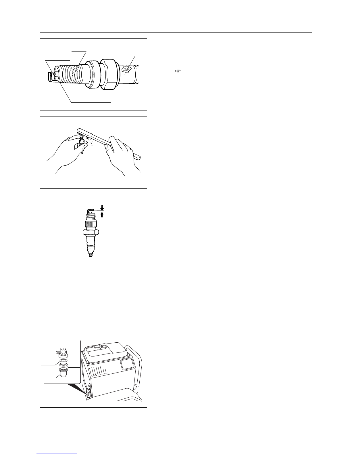
Cleaning
1. Clean the spark plug using a wire brush or plug cleaner.
2. Grind the electrode with sandpaper to adjust the gap as
specified.
Standard clearance : 0.9 to 1.0 mm
3. Replace the spark plug.
7.7.3 Fuel Cock (Fuel Filter)
• Clean fuel filter every 100 hours of operation.
• Clean filter in a neat non-dusty place.
Cleaning
1. Check and confirm that fuel cock is closed.
NOTE
2. Remove filter pot, oil seal and fuel filter.
3. Remove deposits (dust or water etc.) inside of filter pot.
– 39 –
7
MAINTENANCE
2. Remove the spark plug using a plug wrench.
3. Check the plug for the following points and clean or
replace it as necessary. (Specifications for spark plug :
Page 11)
•Presence or absence of breakage of the insulator
•Worn electrode
• Carbon deposit
• Damage to and breakage of gasket
•Degree of burning of insulator in spark section
Degree of burning
Damage
Breakage
Wear, carbon deposit
Fuel
filter
Oil
seal
Filter
pot
Page 45
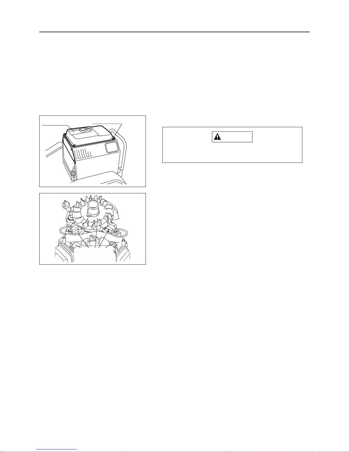
7.7.4 Blower Housing and Cooling Fan
Remove the blower housing after engine
becomes cool.
1. Remove all the fuel completely from fuel tank.
2. Remove cover in front part of fuel tank.
3. Remove attaching bolts (4 pcs.) for fuel tank.
4. Move fuel tank to forward position and fix it.
5. Remove blower housing fixing bolts and detach the
shroud.
6. Inspect cooling fins for dirt or dust. Clean with compressed air.
CAUTION
– 40 –
7
MAINTENANCE
4. Clean inside of filter pot, oil seal,fuel filter in clean
kerosene.
5. Attach filter pot, oil seal and fuel filter.
Fuel tank
Attaching bolt
Remove dirt
or dust around
these areas
Page 46
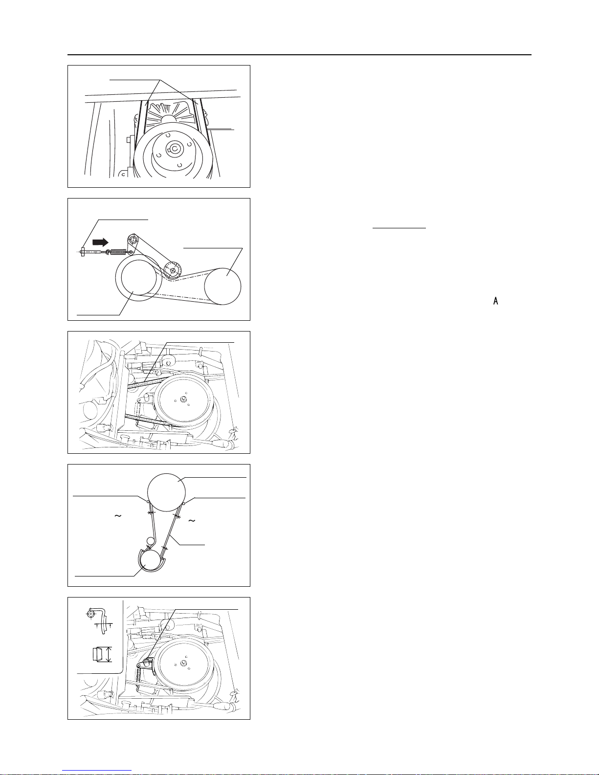
Adjustment
Adjust V belt only when V belt slips during driving. V belt should be always in tension during
operation.
1. To adjust V belt, turn adjusting nut in direction
.
NOTE
7.8.2 Blade Rotary V Belt
Inspection
1. Visually check for damage on V belt. If any damage is
found, replace the V belt.
Adjustment
After replacing V belt, make adjustment as follows :
1. Set the engine side clearance at belt stopper A 2 to 4 mm
and B 10 mm.
2. Set the clearance between rotary belt holder and V belt
with 3 to 5 mm (when belt slips out of rotary, check the
clearance on belt holder at rotary side).
– 41 –
7
MAINTENANCE
7.8 ADJUSTMENT
7.8.1 V Belt for Driving
Inspection
1. Visually check for damage on V belt. If any damage is
found, replace the V belt.
7.8.3 Rotary Stopper
Inspection
1. Inspect and check whether blade stops within 4 seconds
after putting blade clutch lever to OFF. If cutter does not
stop within 4 seconds, check wearing of lining. If lining
is 20 mm or less, ask the dealer to replace it.
Driving V belt
A
Engine pulley
Adjusting nut
HST pulley
Rotary V belt
Rotary belt holder
Engine pulley
V belt
3
5mm
A
B
3
5mm
20
Rotary belt holder
Cutting blade pulley
Rotary stopper
Page 47
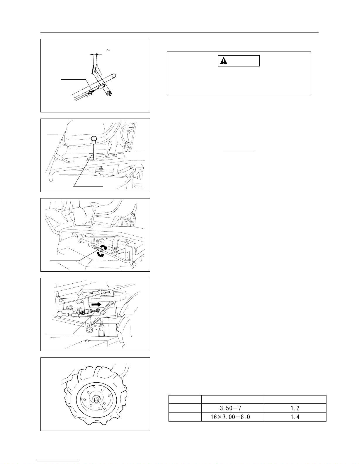
7.8.5 HST Lever
Adjustment is not needed unless the machine
is overhauled. When "Neutral" position of HST
lever is not correctly adjusted, the machine will
slightly move forward or backward.
1. Move HST lever to "Neutral" position.
2. Adjust by turning the turnbuckle of HST lever.
If machine moves forward slightly :
Tu rn the turnbuckle in A direction.
If machine moves backward slightly :
Tu rn the turnbuckle in B direction.
NOTE
When HST lever returns to "Neutral" while driving :
Remove seat, move tension bolt at the foot of
HST lever in direction of arrow and adjust the
lever movement.
– 42 –
7
MAINTENANCE
7.8.4 Brake Pedal
If brake pedal play increases, immediately
make the following adjustment. Poor brake
adjustment may cause accidents.
Adjust the brake pedal play with the wire adjust nut in such a
way that when the brake pedal is depressed slightly, the play
is 15 to 20 mm at the end.
CAUTION
7.8.6 Tire Pressure
1. Check the air pressure of the front and rear tires. Adjust if
required.
Tire size
Air pressure (kg/cm
2
)
Front wheel
Rear wheel
Turnbuckle
B
Adjust nut
15
20mm
Tension bolt
HST lever
A
Page 48
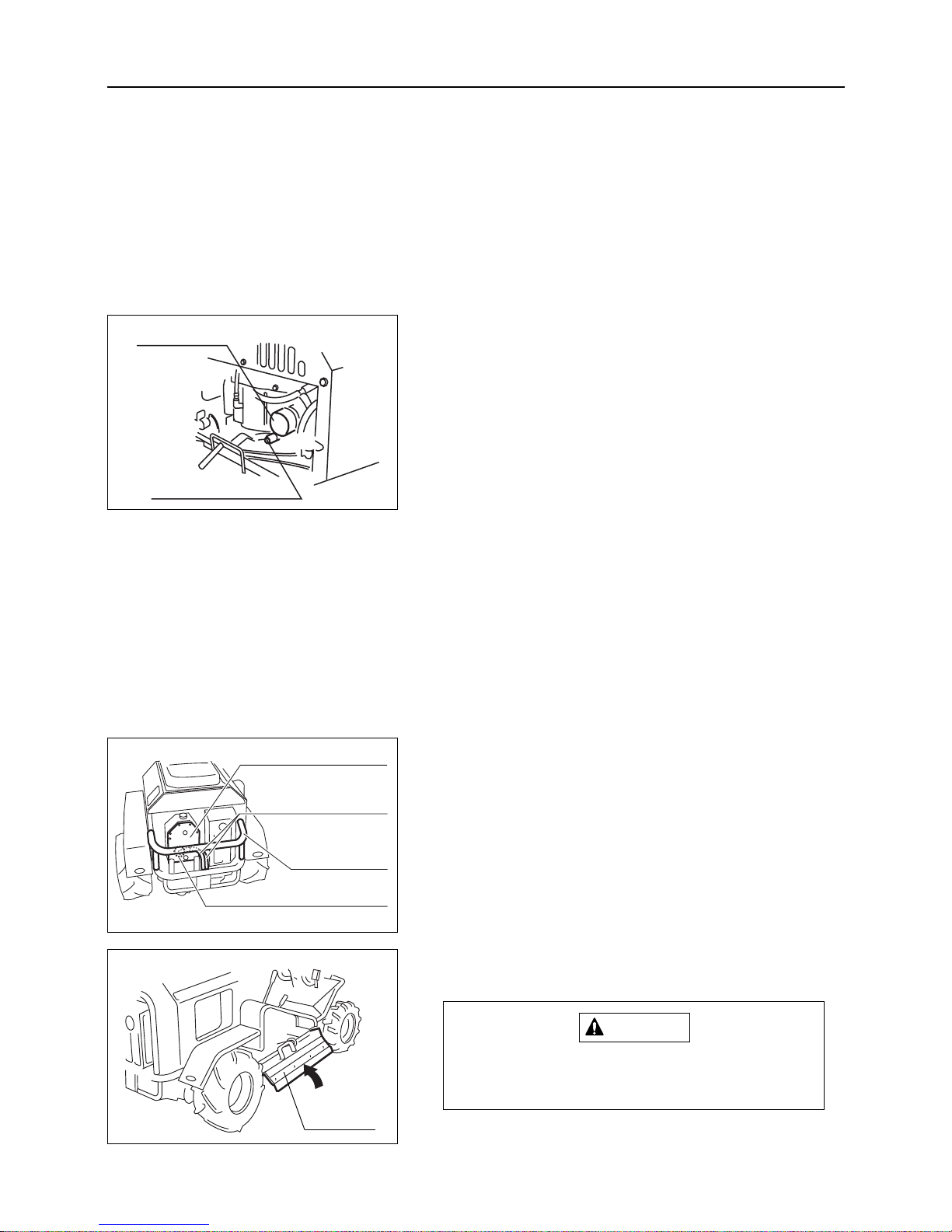
7.9.2 Fuel Pipe, Engine Oil Drain Pipe, and
HST Oil Tank Connection Hose
Rubber products, such as fuel pipe, deteriorate even if they
are not used.
Replace them, together with the tightening handle, with new
ones every three years.
(When they are damaged, replace them at once.)
– 43 –
7
MAINTENANCE
7.9 REPLACEMENT
7.9.1 Oil filter (CM1801)
Replace oil filter every 100 hours of operation.
1. Before installing new filter wipe new oil on filter gasket.
2. Turn the filter by hand until it comes into contact with filter adapter gasket, then use tool to further tighten turning
1/2 to 3/4 turns.
3. Remove oil gauge and pour slowly new oil with appropriate grade and viscosity.
4. When checking oil level, insert the oil gauge completely
before removing again and confirming the level.
5. Start engine and check for oil leakage.
7.9.3 HST Oil filter (CM1801)
Replace the HST oil filter every 500 operating hours.
1. Remove the bumper.
2. Drain oil in the tank. ( Page 32)
2. Take off the oil tank connection hose.
3. Take off the oil tank cover and replace the inside oil filter
with a new oil filter.
4. Install the oil tank cover and oil tank connection hose.
5. Put in HST oil. ( Page 32)
6. Install the bumper.
7.9.4 Blade
When handling cutter blade use thick gloves or
wrap the blade with cloth and handle with care
in order to prevent injuries.
1. Open the right hand side grass outlet cover.
CAUTION
Oil tank cover
Oil tank connection hose
Bumper
Oil filter position
Oil filter
Oil drain plug
Grass outlet cover
Page 49
7
7.10 AFTER-USE MAINTENANCE
(Normal use)
Remove all dirt, water and foreign objects from the
body. Do not use water to wash the engine, the operation panel, or the filling plugs/caps. Water will damage parts and cause rust built up.
Cover the vehicle with a water-proof sheet when placing it outdoors.
(In cold season)
Remove all dirt, water and foreign objects from the
body. Any remaining dirt will freeze and cause malfunctions. Place the vehicle on a concrete floor, dry
firm ground or wooden blocks.
Cover the vehicle with a water-proof sheet when placing it outdoors.
If the vehicle freezes do not operate, do not
force movement. Melt ice with (hot) water or
wait until the vehicle is not frozen. Please take
special note that our company will not take the
responsibility for any failures caused by forced
movements.
NOTE
– 44 –
MAINTENANCE
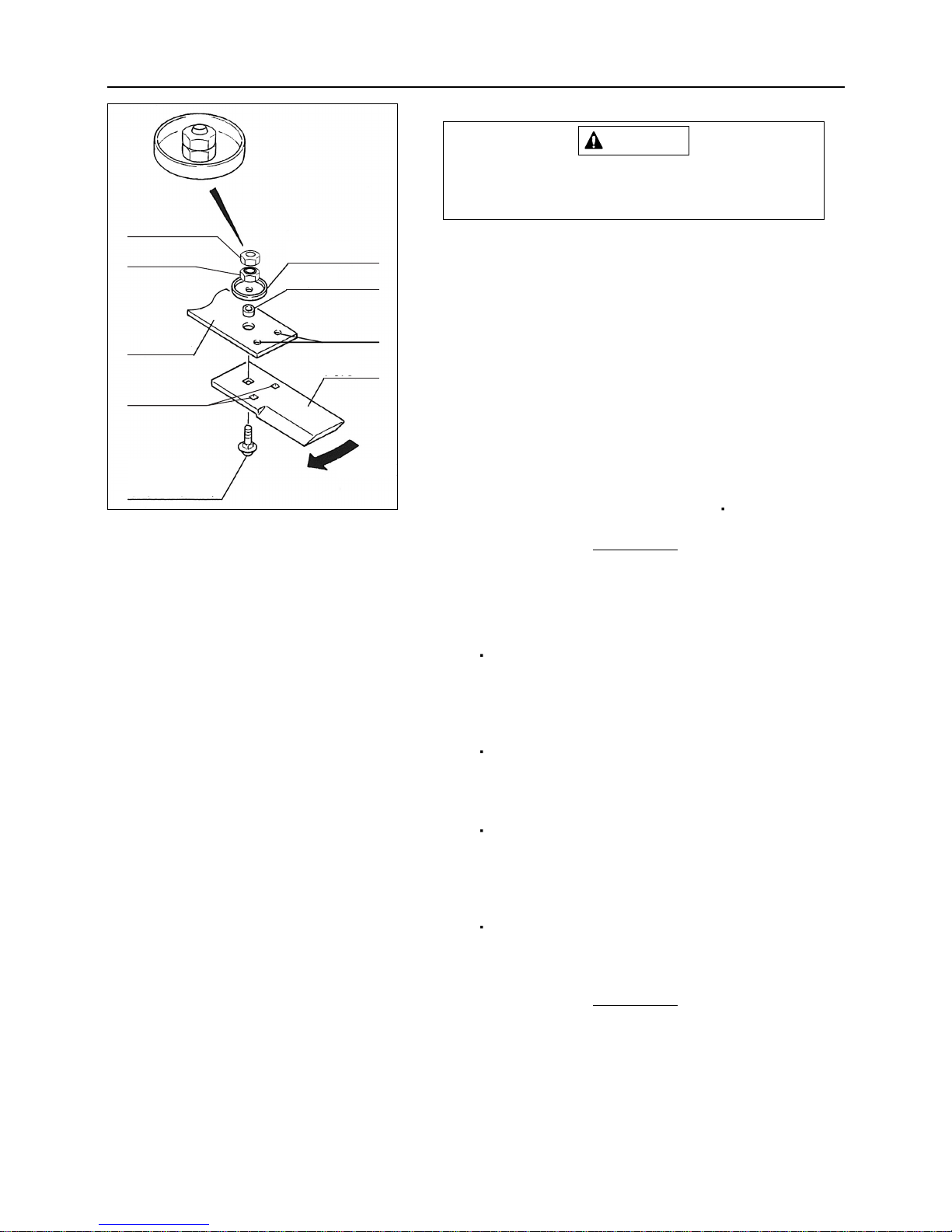
2. Align the stay hole (C) with the cutter blade hole (D).
Because the cup square neck bolt wears out,
be sure to check it for wear.When it is badly
worn away, replace it.
3. Insert a high-strength rod-like thing (such as a screwdriver) into the hole (C or D) (one is acceptable) and lock the
cutter blade.
4. Using a ring spanner or socket wrench, remove the upper
nut (A) and the lower nut (B) in that order and take off
the cutter blade.
5. Place a new cutter blade below the stay and let the cup
square neck bolt pass through from below.
6.
Let the cup square neck bolt pass through the collar and cap
.
7. Align the stay hole (C) with the cutter blade hole (D).
8.
Insert a high-strength rod-like thing (such as a screwdriver) into
the hole (C or D) (one is acceptable) and lock the cutter blade.
9. Tighten the lower nut (B) with specified torque.
10. Tighten the upper nut (A) with specified torque.
Specified torque: M12 = 450 to 550 kgf
cm
Always split the cotter pin vertically.
NOTE
CAUTION
Nut(A)
Nut(B)
Stay
Hole(D)
Cop square neck bolt
Cap
Collar
Hole(C)
Cutter blade
Direction of rotation
Page 50
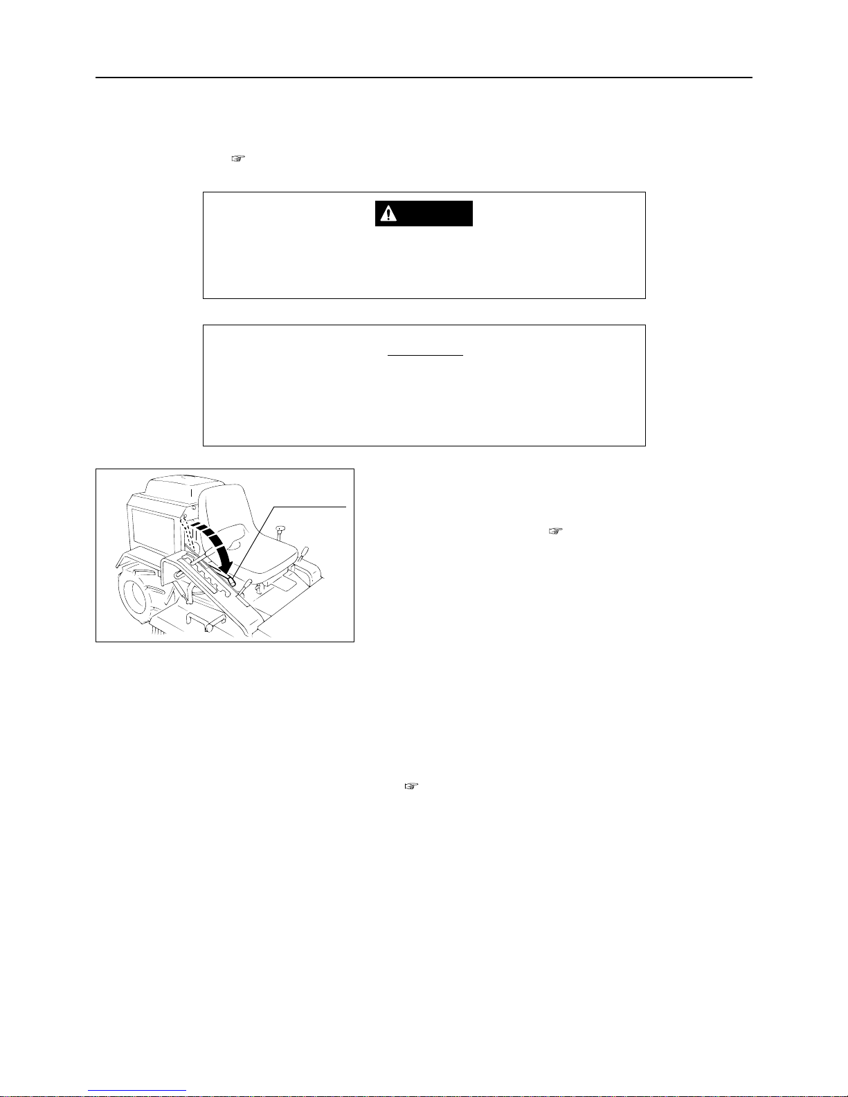
8.1 VEHICLE BODY
1. Inspect each area in accordance with the "REGULAR
INSPECTION CHART" ( Page 25).
Carry out servicing if a defective condition is found.
2. Clean the external surface with a cloth moistened with oil.
Lubricate areas which are apt to get rusty.
3. Set the air pressure of the tires at a value slightly higher than
the standard value.
4. Apply blocking in front of and behind the front wheels.
5. Move blade clutch lever to "ON" position.
6. Lubricate and grease areas to be lubricated and greased.
(Pages 33 and 34)
7. Remove key from the main switch.
– 45 –
8
STORAGE (LONG TERM)
8. STORAGE (LONG TERM)
When storing the vehicle for a long time, appropriate maintenance is required for future use. After performing the
after-use maintenance ( page 44), follow the instructions below.
Do not store the vehicles, battery, or fuel near open flames or in
a high temperature area. Doing so may cause accidental fires.
DANGER
Do not store the vehicle in a dusty or damp place. Be sure to
put a cover (vinyl sheet, etc,) on the vehicle after the engine has
become cool.
NOTE
Blade clutch
lever
Page 51
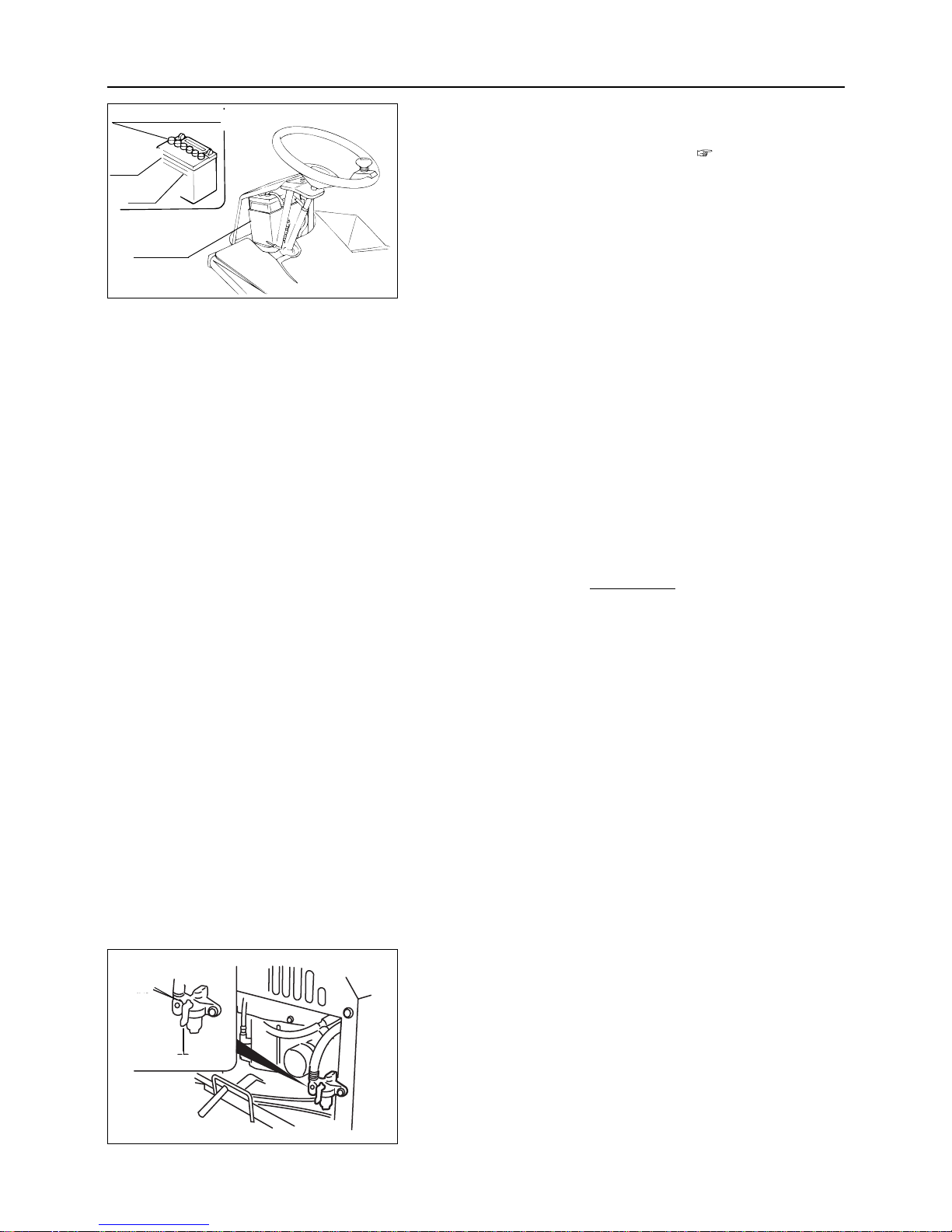
8.3 ENGINE
• Remove all fuel from the carburetor and
fuel tank before storing the vehicle for a
long time. Fuel in the carburetor will
deteriorate if left unused for a long time,
causing poor starting, or unstable operation of the engine. Do not use fuel which
has been left unused for a long time.
• Refer to the engine operation manual for
more details about long term storage of
the engine.
NOTE
– 46 –
8
STORAGE (LONG TERM)
8.2 BATTERY
1. Remove the battery from the vehicle. ( Page 35)
(When storing with battery in machine, disconnect minus
battery cable.)
2. Check the battery fluid level and add fluid as necessary.
3. Store the battery in a dry area with low temperature.
Notice:
Although the battery could be used without any recharges for
approximately 6 months, it would be recommended to
recharge before discharge for the battery's longer life.
8.3.1 Fuel Cock
1. Turn the fuel cock to "CLOSE" to stop fuel supply.
Battery cap
Battery
Upper
limit
Lower
limit
Close
Open
Page 52
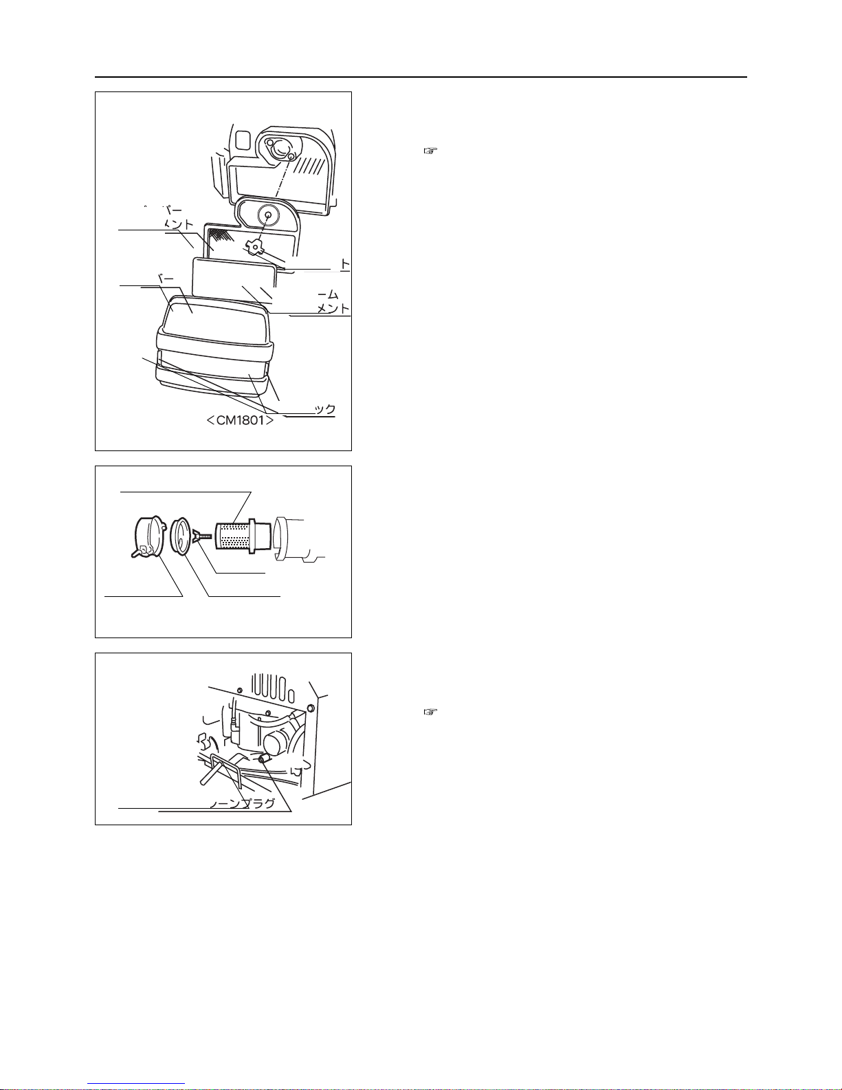
8.3.3 Replacing Engine Oil
1. Drain all engine oil and refill engine with new engine oil.
(Pages 30)
– 47 –
8
STORAGE (LONG TERM)
8.3.2 Cleaning Air Cleaner Element
1. Remove the air cleaner element and thoroughly clean it.
(Pages 37 and 38)
Air cleaner element
< CM1305 >
< CM1801 >
Air cleaner
Wing bolt
Dust cover
Oil drain plug
Paper
element
Cover
Wing bolt
Form
element
Hook
Page 53
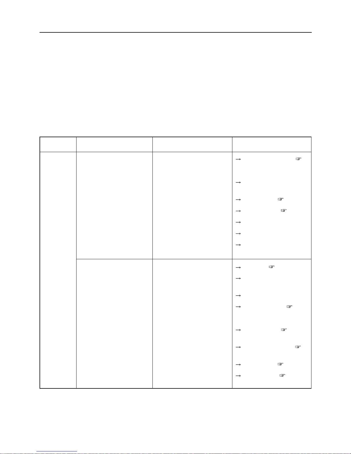
9
TROUBLESHOOTING
– 48 –
9. TROUBLESHOOTING
• If any malfunction or abnormal operation is found, immediately stop using the machine and make an
appropriate repair referring to the troubleshooting chart shown below. If the malfunction is not listed in
the chart or the suggested repair does not solve the problem, consult your dealer or one of our service
centers.
• Some repair contents require specialized service knowledge. Request your dealer or one of our service
centers for such repairs.
9.1 TROUBLESHOOTING CHART
Area
Engine
Malfunction
Engine does not start
Hard to start (Difficult in starting)
Possible cause
• Blade clutch lever is not in the
"OFF" position. (Safety device
is actuated.)
• Brake pedal is not depressed.
(Safety device is working.)
• Battery is over-discharged.
• Battery cable is disconnected.
• Fuse is blow.
• Open circuit or contact failure
of wiring
• Lack of fuel
• Air or water in fuel
• Excessive intake of fuel
• Engine oil insufficiency or
poor quality (High oil viscosity)
• Poor ignition due to dirt on
spark plug or poor sparking
• Insufficient capacity of battery
(Poor electric starting)
• Impurities in fuel circuit
Corrective action
Put the lever to "OFF". (
Page 15)
Depress brake pedal.
Charge battery.( Page 35)
Replace battery. ( Page 36)
Connect cable.
Replace.
Repair. (Consult dealer.)
Replenish. ( Page 13)
Check pipe and tightening
band. Repair or replace.
Start after interval.
Replenish or replace. ( Page
30)
Clean or replace.( Page 38)
Replenish battery fluid.(
Page 35)
Charge battery.( Page 35)
Clean fuel cock.( Page 39)
Page 54
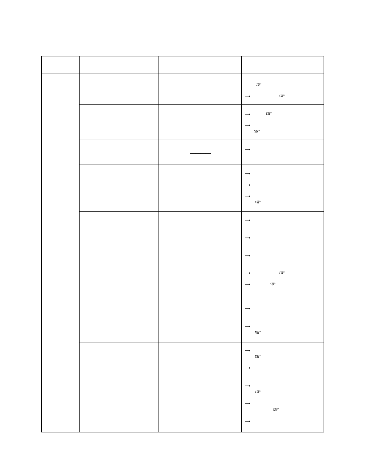
9
TROUBLESHOOTING
– 49 –
Area
Engine
Malfunction
Engine stalls soon
Engine stops abruptly
Improper idling
(lrregular engine speed)
Poor power or acceleration
Abnormal noises or vibrations
are made in or around the engine
Excessive engine oil
Engine overheating
Excessive fuel consumption
Excessive black smoke
(Abnormal exhaust)
Possible cause
• Fuel cock is not opened
• Insufficient fuel
• No fuel
• Burn due to insufficient or
deteriorated engine oil
•V belt loosened
• Improper accelerator adjustment
• Clogging of air cleaner
• Looseness of engine mounting
bolts
•Others
• Engine oil leak
• Insufficient engine oil
• Blower housing and cooling
fin clogging
• Fuel leak from fuel system
• Clogged air cleaner
• Choke not opened completely
• Poor compression
• Clogged air cleaner
• Excessive oil intake
• Poor fuel
Corrective action
Open fuel cock.
( Page 15)
Replenish. ( Page 13)
Add. ( Page 13)
Check and add oil.
( Page 30)
Consult dealer.
Adjust.
Consult dealer.
Clean or replace.
( Pages 37 and 38)
Check and carry out additional
tightening.
Consult dealer.
Check and repair.
Replenish. ( Page 30)
Clean. ( Page 40)
Check and repair.
(Consult dealer.)
Clean or replace.
( Pages 37 and 38)
Put choke to FULL position.
( Page 18)
Check and repair.
(Consult dealer.)
Clean or replace.
( Pages 37 and 38)
After checking adjust oil
volume. ( Page 30)
Replace fuel.
Page 55
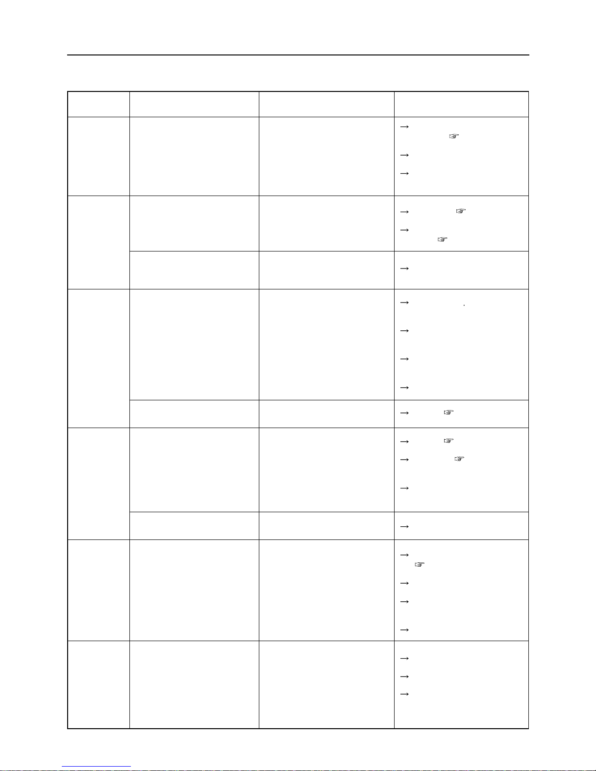
9
TROUBLESHOOTING
– 50 –
Area
Power
transmission
system
Engine
Brake system
Steering
system
Chassis
Lighting
system
Malfunction
White smoke or blue smoke
comes out. (Abnormal exhaust)
Never move unit with HST
lever forward or reverse.
The unit moves even when HST
lever is in neutral position.
Not effective
Excessive play of brake pedal.
Heavy steering
Cannot drive straight.
Abnormal vibration of the
chassis
Head lamp failure
Possible cause
• An excessive amount of
engine oil is put in.
• Improper fuel
• Worn cylinder or piston ring
• Insufficient HST oil
• Parking brake is applied.
•
Adjustment of neutral position
of HST speed shift is not correct.
• Worn out brake lining
• Oil penetrates within brake
drum.
• Water penetrates inside of
drum.
• Worn out tire
• Incorrect adjustment
• Incorrect tire air pressure
• Insufficient greasing for king
pin
• Maifunction inside of steering
gear
• Incorrect tie-rod adjustment
• Incorrect tire air pressure
adjustment
• Loose tire fixing bolt
• Breakage of wheel bearing
• Crack of tire
• Improper wiring
• Bulb is disconnected.
• Blow fuse
Corrective action
After checking adjust oil
volume. ( Page 30)
Replace fuel.
Check and repair.
(Consult dealer.)
Replenish. ( Page 32)
Release parking brake lock
lever. ( Page 19)
Adjust. (Consult dealer.)
Replace lining
(Ask dealer to do the job.)
Replace oil seal.
(Ask dealer to do the job.)
Engine brake some times to
dry water inside of drum.
Replace tire.
Adjust. ( Page 42)
Adjust. ( Page 42)
Lubricate. (
Page 33)
Repair.
(Ask dealer to do the job.)
Adjust.
Adjust tire air pressure.
( Page 42)
Retighten.
Replace.
(Ask dealer to do the job.)
Replace.
Connect properly.
Replace.
Replace.
Page 56
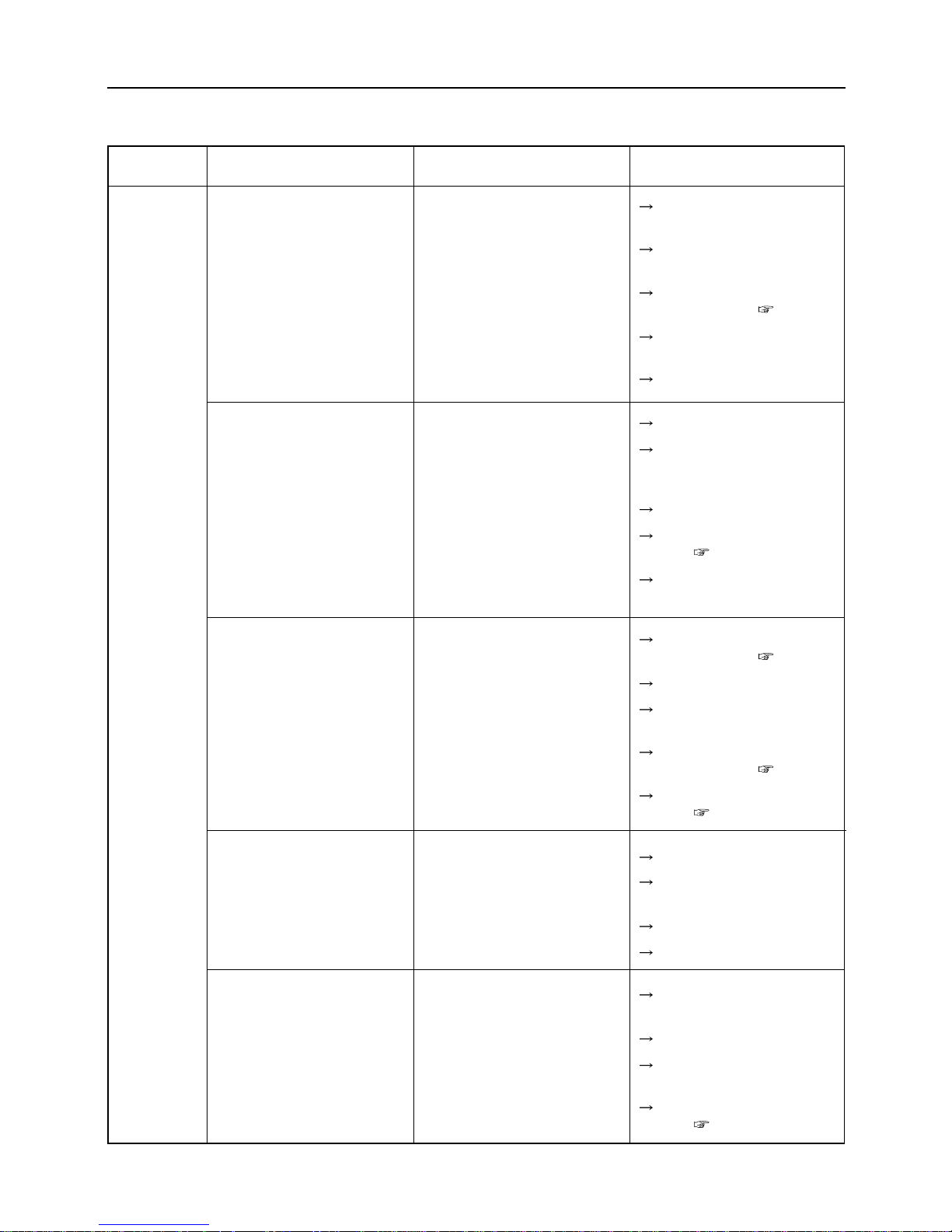
9
TROUBLESHOOTING
– 51 –
Area
Grass cutter
devices
Mulfunction
Mown grass not discharged
well
Some grass is left unmown.
The mower cuts into the soil.
The belt slips
Extreme shaking
Possible cause
• Wet grass
• Grass too long
•Mowing height too low
• Low engine speed
• High work speed
• High work speed
• Low engine speed
• Grass too long
• Wear and breakage of cutter
•
Accumulation of grass on the
internal surface of the rotary cover
•Mowing height too low
• High swing speed
• Ground contours
•Too many bumps and dips in
the ground
• Bent mowing blade
• Low belt tension
• Rotary cover clogged with
grass
•
Grass accumulated in the pulley
• Worn belt
• Grass accumulated in the
rotary cover and pulley
• Damaged belt
• Damaged pulley
• Damaged blade
Corrective action
Perform the operation after
grass becomes dry.
Mow twice with a higher
mowing height.
Set the mower to a higher
mowing height. ( Page 24)
Set the mower to the
maximum motor speed.
Work more slowly.
Work more slowly.
Set the mower to the maximum motor speed. (Check
engine speed.)
Mow twice.
Replace the blade with a new
one. ( Pages 43 and 44)
Clean the internal surface of
the rotary cover.
Set the mower to a higher
mowing height. ( Page 24)
Reduce swing speed.
Change the moving pattern.
(mowing direction, etc.)
Set the mower to a higher
mowing height. ( Page 24)
Replace the blade with a new
one. ( Pages 43 and 44)
Adjust the belt tension.
Take out the jammed grass and
clean the inside of rotary cover.
Clean the pulley.
Replace the belt with a new one.
Clean the rotary cover and
pulley.
Replace the belt with a new one.
Replace the pulley with a new
one.
Replace the blade with a new
one. ( Pages 43 and 44)
Page 57
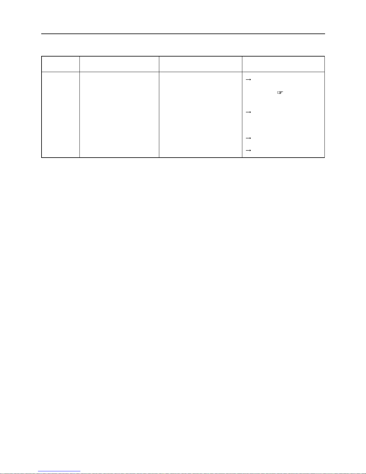
9
TROUBLESHOOTING
– 52 –
Area
Grass cutter
devices
Malfunction
Cutter overloaded
Possible cause
• Poor balance of blade
• Low engine speed
• Operating speed too high
• Grass accumulating or coiling
around blade or around shaft
Corrective action
Replace the blade with a new
one or balance the blade
properly. ( Pages 43 and
44)
Increase engine speed to a
maximum value.
(Check engine speed.)
Slow down operating speed.
Clean up blade.
Page 58
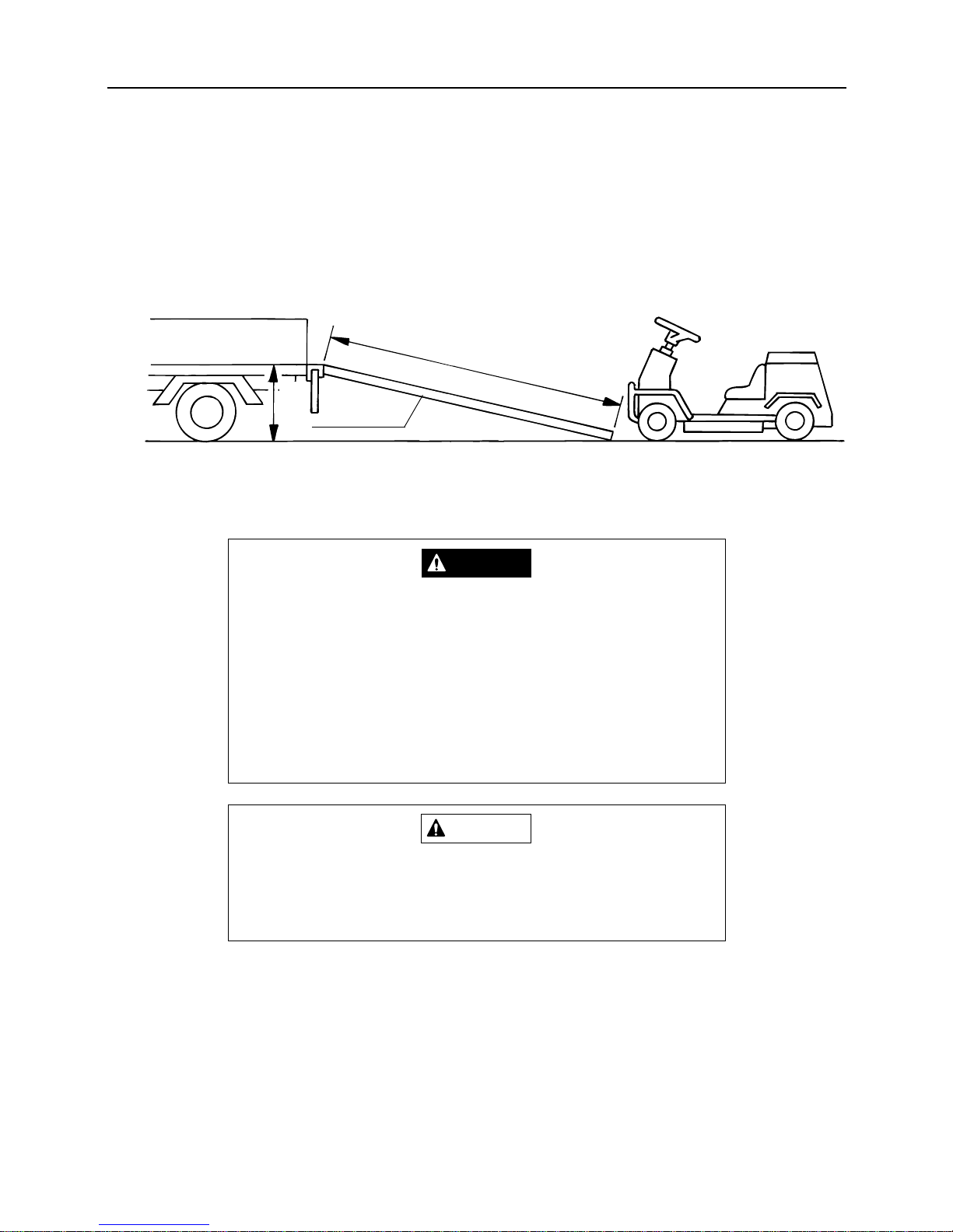
10. TRANSPORTATION OF/WITH THIS VEHICLE
When loading and unloading the machine onto or from truck, follow the procedures below.
1. Prepare running boards with enough strength (durable to hold both machine and driver's weight), width (twice
width of tire width), length (more than three times as long as the truck loading body height), and abrasive surface. Place the boards as shown below so that the boards firmly keep their positions even when the machine
rides on them.
2. Securely hook the running boards to truck so that there is no difference in height between the boards and the
truck's loading bed.
10
TRANSPORTATION OF/WITH THIS VEHICLE
– 53 –
• Do not allow any one to come near the machine, truck, and
running board while loading or unloading the machine.
• Do not turn on the running boards. The machine may drop
off the running boards.
• When moving up or down the running boards, drive the vehi-
cle slowly at low speed.
DANGER
When the machine is loading on the place between the truck
and the running board, beware of the machine's center of gravi-
ty because it may move suddenly.
CAUTION
More than 3 times as long as height
Height
Running boards
Page 59
Memo of address and telephone number
(Name of dealer)
Sales Headquarters
09437(5)2195 FAX (5)4396
Tokyo Headquarters
03(3552)6255 FAX (3552)6288
Foreign Trade Center
03(3552)6277 FAX (3552)6288
Tokyo Center
03(3552)6255 FAX (3552)6288
Sendai Center
022(281)1255 FAX (281)3141
Saitama Center
0495(77)4511 FAX (77)2949
Osaka Center
0790(42)6031 FAX (42)6035
Hiroshima Center
0824(34)5996 FAX (34)5997
Fukuoka Center
0943(76)2583 FAX (75)5126
CHIKUSUI CANYCOM, INC.
We prohibit unauthorized reprinting and reproduction of this document.
 Loading...