

Page 1

Read this manual completely before operating or maintaining this machine.
Failure to follow safety precautions could result in serious injury or death.
Keep this manual for future reference by you and by all those who operate
and maintain this machine.
CHIKUSUI CANYCOM, INC.
90-1 Fukumasu, Yoshii-machi,
Ukiha-shi, Fukuoka, Japan 839-1396
Tel.+81-(0)943-75-2195 Fax.+81-(0)943-75-4396
Front Flail Brushcutter
CG431 Tractor
Operator's Manual
5116 5106 000
Page 2

http://www.canycom.co.jp/
■
Sales Headquarters TEL +81-(0)943-75-2195 FAX +81-(0)943-75-4396
All rights reserved. Unauthorized use or reproduction of this material is prohibited.
Authorized Dealer
CHIKUSUI CANYCOM, INC.
Page 3

Notice to Users and Maintenance Personnel
• This machine can kill you if the safety precautions in this manual and on the
labels attached to this machine are not followed. Read and understand this
manual and the safety labels on the machine thoroughly before using or
servicing the machine. Always follow the instructions and safety precautions,
or serious injury or death could result.
• This machine should only be used with the implements that are specically
designed for this machine, or expressly certied for the use with this machine,
for the intended purpose of this machine: brushcutting and haymaking. Any
use other than these, i.e. towing, pushing other vehicle or material, carrying
peo p le other than the operator o r material, o r any other us e other than
brushcutting or haymaking, or any use with implements other than the ones
mentioned above could be dangerous.
• This machine may not be operated on public road or what is considered to
be public road. It is the sole responsibility of the operator to consult the local
regulations.
• Do not modify this machine, or do not operate this machine with safety covers
removed or open. A serious accident could result.
Thank you for purchasing this machine.
This manual provides information needed for safe and effective use and maintenace of this
machine to those who operate or maintain the machine. Make sure to read and understand
the manual thoroughly before operating or servicing the machine. Also make sure to read
the separate operator's manual for engine.
• Store this manual in a safe, accessible place for easy reference.
Page 4

Warning Term Denition
Indicates an imminently hazardous situation which will result
in death or serious injury if the user does not follow the
procedures or the instructions.
Indicates a potentially hazardous situation which could result
in death or serious injury if the user does not follow the
procedures or the instructions.
Indicates a potentially hazardous situation which could result
in minor to moderate injury or damage to the machine if the
user does not follow the procedures or the instructions.
Indicates important information which needs particular
attention.
In this manual, the following four warning terms are used to signal the four levels of hazard
(or seriousness of possible accidents). Read and understand what they mean and always
follow the instructions in this manual.
Warning Terms Used in this Manual
NOTE
Notice to Owner
• Be sure that everyone who uses this machine, including those who rent or
lease this machine, receives a copy of this Operator's Manual and understands
the importance of reading and following the information in this manual.
Page 5

Warranty and After-Sales Service
Warranty
Consult your local CANYCOM dealer or our company’s sales department regarding service
orders or any questions or problems that may arise when using this machine. Please
make sure to have the product name, serial number, and the make and type of engine
handy at the time of contact. The model and serial numbers can be found on the model
label as shown below, and the make and type of the engine can be found in Chapter 3
"Specications" of this manual (Page14).
After-Sales Service
Location of Model Label Model Label
The replacement or repair parts for this product shall remain available for seven years after
the production of this type of machine is discontinued.
Availability of Spare Parts
5116M-0004-030US
2011 1590
CG431
5116M-0004-010E
Location of Model Label
CHIKUSUI CANYCOM, INC. provides you a warranty through Canycom U.S.A. A copy of
this warranty is reproduced in the back of the manual.
Page 6

Contents
1. Safety 1
Safety Labels . . . . . . . . . . . . . . . . . . . . . . . . . . . . . . . . . . . 1
Safety Precautions. . . . . . . . . . . . . . . . . . . . . . . . . . . . . . . 3
Training
. . . . . . . . . . . . . . . . . . . . . . . . . . . . . . . . . . . . . . . . . . . . . . . . . . . . . . .
3
Preparation . . . . . . . . . . . . . . . . . . . . . . . . . . . . . . . . . . . . . . . . . . . . . . . . . . . . 4
Operation. . . . . . . . . . . . . . . . . . . . . . . . . . . . . . . . . . . . . . . . . . . . . . . . . . . . . . 4
Servicing
. . . . . . . . . . . . . . . . . . . . . . . . . . . . . . . . . . . . . . . . . . . . . . . . . . . . . .
8
2. Controls and Components 10
Name and Function of Controls . . . . . . . . . . . . . . . . . . . 10
3. Specications 14
Product Specications . . . . . . . . . . . . . . . . . . . . . . . . . . 14
Contents of Tool Bag
. . . . . . . . . . . . . . . . . . . . . . . . . . .
15
4. Operation 16
Preparation
. . . . . . . . . . . . . . . . . . . . . . . . . . . . . . . . . . . .
16
Pre-start up Inspection . . . . . . . . . . . . . . . . . . . . . . . . . . . . . . . . . . . . . . . . . 16
Checking and Filling Fuel . . . . . . . . . . . . . . . . . . . . . . . . . . . . . . . . . . . . . . . 16
Unfolding/Folding Step . . . . . . . . . . . . . . . . . . . . . . . . . . . . . . . . . . . . . . . . . 17
Page 7

Driving. . . . . . . . . . . . . . . . . . . . . . . . . . . . . . . . . . . . . . . . 18
Starting . . . . . . . . . . . . . . . . . . . . . . . . . . . . . . . . . . . . . . . . . . . . . . . . . . . . . . 18
Driving . . . . . . . . . . . . . . . . . . . . . . . . . . . . . . . . . . . . . . . . . . . . . . . . . . . . . . . 22
Stopping . . . . . . . . . . . . . . . . . . . . . . . . . . . . . . . . . . . . . . . . . . . . . . . . . . . . . 24
Working . . . . . . . . . . . . . . . . . . . . . . . . . . . . . . . . . . . . . . 26
Operating Implement . . . . . . . . . . . . . . . . . . . . . . . . . . . . . . . . . . . . . . . . . . . 27
Changing PTO Speed (Variable PTO Speed Model Only) . . . . . . . . . . . . . . 29
Translating Implement
. . . . . . . . . . . . . . . . . . . . . . . . . . . . . . . . . . . . . . . . . .
30
Levelling Step . . . . . . . . . . . . . . . . . . . . . . . . . . . . . . . . . . . . . . . . . . . . . . . . . 31
Hydraulic Cooling Fan
. . . . . . . . . . . . . . . . . . . . . . . . . . . . . . . . . . . . . . . . . .
32
Fire Extinguisher . . . . . . . . . . . . . . . . . . . . . . . . . . . . . . . 33
Fire Extinguisher Location. . . . . . . . . . . . . . . . . . . . . . . . . . . . . . . . . . . . . . . 33
Using Fire Extinguisher . . . . . . . . . . . . . . . . . . . . . . . . . . . . . . . . . . . . . . . . . 33
5. Maintenance 34
Maintenance Schedule . . . . . . . . . . . . . . . . . . . . . . . . . . 34
List of Fluids and Lubricants
. . . . . . . . . . . . . . . . . . . . .
39
Grease Points . . . . . . . . . . . . . . . . . . . . . . . . . . . . . . . . . . 40
List of Consumables and Spares . . . . . . . . . . . . . . . . . . 40
Body Panels
. . . . . . . . . . . . . . . . . . . . . . . . . . . . . . . . . . .
43
Opening Top Cover. . . . . . . . . . . . . . . . . . . . . . . . . . . . . . . . . . . . . . . . . . . . . 43
Removing Side Covers. . . . . . . . . . . . . . . . . . . . . . . . . . . . . . . . . . . . . . . . . . 44
Removing Front Cover . . . . . . . . . . . . . . . . . . . . . . . . . . . . . . . . . . . . . . . . . . 44
Removing Controls Cover . . . . . . . . . . . . . . . . . . . . . . . . . . . . . . . . . . . . . . . 44
Page 8

Engine . . . . . . . . . . . . . . . . . . . . . . . . . . . . . . . . . . . . . . . . 45
Engine Oil . . . . . . . . . . . . . . . . . . . . . . . . . . . . . . . . . . . . . . . . . . . . . . . . . . . . 45
Oil Filter . . . . . . . . . . . . . . . . . . . . . . . . . . . . . . . . . . . . . . . . . . . . . . . . . . . . . . 47
Coolant. . . . . . . . . . . . . . . . . . . . . . . . . . . . . . . . . . . . . . . . . . . . . . . . . . . . . . . 47
Air Cleaner . . . . . . . . . . . . . . . . . . . . . . . . . . . . . . . . . . . . . . . . . . . . . . . . . . . 50
Fan Belt
. . . . . . . . . . . . . . . . . . . . . . . . . . . . . . . . . . . . . . . . . . . . . . . . . . . . . .
51
Fuel System . . . . . . . . . . . . . . . . . . . . . . . . . . . . . . . . . . . 52
Bleeding
. . . . . . . . . . . . . . . . . . . . . . . . . . . . . . . . . . . . . . . . . . . . . . . . . . . . . .
52
Draining Water . . . . . . . . . . . . . . . . . . . . . . . . . . . . . . . . . . . . . . . . . . . . . . . . 52
Fuel Filter Cartridge
. . . . . . . . . . . . . . . . . . . . . . . . . . . . . . . . . . . . . . . . . . . .
53
Hydraulic System . . . . . . . . . . . . . . . . . . . . . . . . . . . . . . . 54
Hydraulic Fluid . . . . . . . . . . . . . . . . . . . . . . . . . . . . . . . . . . . . . . . . . . . . . . . . 54
Suction Filter. . . . . . . . . . . . . . . . . . . . . . . . . . . . . . . . . . . . . . . . . . . . . . . . . . 56
Return Filter Element . . . . . . . . . . . . . . . . . . . . . . . . . . . . . . . . . . . . . . . . . . . 57
Drive Train. . . . . . . . . . . . . . . . . . . . . . . . . . . . . . . . . . . . . 58
Track . . . . . . . . . . . . . . . . . . . . . . . . . . . . . . . . . . . . . . . . . . . . . . . . . . . . . . . . 58
Drive Motor Lubricant. . . . . . . . . . . . . . . . . . . . . . . . . . . . . . . . . . . . . . . . . . . 59
Greasing . . . . . . . . . . . . . . . . . . . . . . . . . . . . . . . . . . . . . . . . . . . . . . . . . . . . . 60
Control Stick . . . . . . . . . . . . . . . . . . . . . . . . . . . . . . . . . . . . . . . . . . . . . . . . . . 61
Electrical System
. . . . . . . . . . . . . . . . . . . . . . . . . . . . . . .
62
Battery Fluid . . . . . . . . . . . . . . . . . . . . . . . . . . . . . . . . . . . . . . . . . . . . . . . . . . 62
Charging Battery. . . . . . . . . . . . . . . . . . . . . . . . . . . . . . . . . . . . . . . . . . . . . . . 64
Fuses . . . . . . . . . . . . . . . . . . . . . . . . . . . . . . . . . . . . . . . . . . . . . . . . . . . . . . . . 65
Slow-Blow Fuses . . . . . . . . . . . . . . . . . . . . . . . . . . . . . . . . . . . . . . . . . . . . . . 66
Imprement. . . . . . . . . . . . . . . . . . . . . . . . . . . . . . . . . . . . . 67
Attaching/Detaching Implement . . . . . . . . . . . . . . . . . . . . . . . . . . . . . . . . . . 67
Page 9

Appendix
• Operator's Manual for Engine
* Be sure to read and understand it together with this manual .
After Use Care . . . . . . . . . . . . . . . . . . . . . . . . . . . . . . . . . 69
After Normal Use . . . . . . . . . . . . . . . . . . . . . . . . . . . . . . . . . . . . . . . . . . . . . . 69
After Cold Weather Use . . . . . . . . . . . . . . . . . . . . . . . . . . . . . . . . . . . . . . . . . 69
Storage . . . . . . . . . . . . . . . . . . . . . . . . . . . . . . . . . . . . . . . 70
6. Troubleshooting 71
Troubleshooting . . . . . . . . . . . . . . . . . . . . . . . . . . . . . . . . 71
7. Transporting 76
Hauling . . . . . . . . . . . . . . . . . . . . . . . . . . . . . . . . . . . . . . . 76
Loading and Unloading . . . . . . . . . . . . . . . . . . . . . . . . . . . . . . . . . . . . . . . . . 76
Hoisting and Towing . . . . . . . . . . . . . . . . . . . . . . . . . . . . 78
Page 10
Safety 1
-1-
Safety Labels
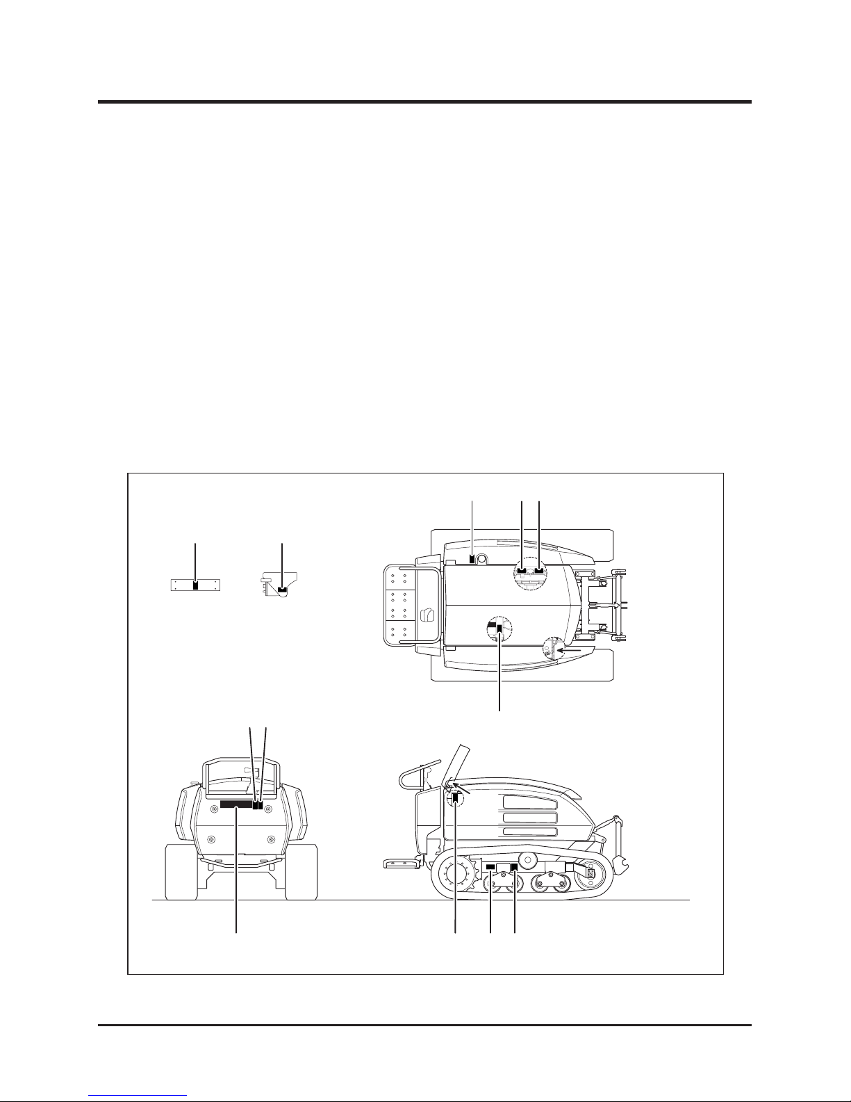
Safety labels shown on the next page are attached to the machine. See the illustration below
for the location and the illustration on the next page for the content of each label on the
machine.
• Locate all warning labels attached to this machine. Read and follow the instructions
and precautions in them. Failure to do so could result in serious injury or death to
the operator or bystanders.
• Keep labels clean and legible. Do not use solvents or gasoline to clean labels.
• Replace these labels immediately if they have been removed, have fallen off or
become illegible. Use part number written on the label or shown in this manual to
order a replacement label from your CANYCOM representative.
View BView A
View B
5116M-0101-010US
View A
5
1 2 3
7 8
42
9 10 116
Page 11

Safety
-2-
1
Explo sion ha zard.
Fla mmable liqu id
p re s en t . Ke e p
awa y a ll ig nit io n
s o u rc es . N e
ve r
drill , cut with gas,
hit or disassemble
.
3670 5138 001
DANGER!
Moving fan blades
ca n se
ve r ha nd
and fingers. Keep
h an d s a wa y
t o
avoid injury.
3683 5026 001
WARNING!
Hot liq uids . B urn
ha zar d. D o N OT
ope n t he
radi ator
cap after operating
this machi ne
.
3677 5045 001
WARNING!
Hot sur face s. Do
NOT tou ch.
3677 5043 001
WARNING!
Tur n the mow er swi tch onl y wh en mowi ng.
Keep it off all the ot her times.
Rep lac e the flai ls wh en da maged or b roken.
Using dama ged o r bro ken fl ails cause damg es
or ac ciden ts du e to imbal ance.
If a vi ne-like object gets tangl ed to the mo
wer
rotor, immed iatel y sto p the engi ne an d rem ove
it.
Such objec t can cause damg es or accid ents
due t o imb alanc e or overlo ading .
D o n ot o pe ra t e o n an
in cli ne st eep er th an 30
degre es.
Do no t tur n on an i nclin e
.
D o n o t o p er a te o n a
slipp ery surfac e
.
L o c a te o bs ta cl es a n d
holes befor e ope ratio n.
I f th e e n g i n e
ap pe ars to st op
due to overheating,
r e a d t h e
Operator's Manual.
Th is m ach in e is
e qu ip ed
w it h a
safegu ard system
to halt the en gine
bef ore it actu ally
overheat s
.
CAU T IO N! CAUTION! CAU T IO N!
D o n o t u s e t h e
mowe r in reverse
m od e wh en th e
m o
w e r d e ck i s
tr an sl at ed t o
th e
side .
Ob jects can
be thrown, causing
i n j u r i e s a n d
property damages
.
WARNING!
5116 5318 000
Read the
Operator's Manual
before operating
or servicing the
machine
.
5116 5323 000
WARNING!
St op the e ng ine
before servicing.
5116 5327 000
WARNING!
Explosion hazard.
Do not use drill,
torch or hammer.
Do not disassemble. Keep
fire away
.
5116 5361 000
WARNING!
Do not undo the
grease nipple at
once. Greas is
under pressure
and can eject the
nipple. Read the
Operator's Manual
when servicing.
5116 5341 000
WARNING!
Always remove the valve
when loosening the
crawler. When installing
the valve, make sure the
O-ing is free of damages.
Install carefully not to jam
the O-ring.
5116 5358 000
CAUTION!
5116M-0101-020US
1. 3670 5138 001 2. 3683 5026 001
7. 5116 5323 000
3. 3677 5045 001 4. 5116 5362 000 5. 3677 5043 001
6. 5116 5318 000
8. 5116 5327 000 9. 5116 5361 000 10. 5116 5341 000
11. 5116 5358 000
E le ct ri c sh oc k
haza rd. Read the
O p e p a t o r ' s
M a n u a l w h e n
servicing.
5116 5362 000
WARNING!
Page 12

Safety 1
-3-
This section contains safety precautions to follow when operating and maintaining the
machine. Read and understand the precautions in this section as well as throughout this
manual and follow them when operating or maintaining machine. Failure to follow safety
precautions could result in property damage, serious injury or death to the operator
or bystanders.
Safety Precautions
All operators and mechanics should receive practical instructions from their employer or
renter. Such instructions should cover the following issues:
• It is essential to familiarize yourself with the controls, safety labels and proper use
of the machine.
• Never allow people unfamiliar with these instructions to operate or service the
machine. Do not let anyone under 18 years of age to operate this machine. Local
regulations may restrict the minimum age for operating this type of machine.
Consult your local authority.
• Operator is responsible for the accidents or hazards caused to other people or to
their property.
• This machine has a riding capacity for one person only. Do not carry any passenger
other than the operator.
• Always keep in mind that attention and concentration is required when working with
ride-on machines.
• Loss of control on a slope cannot be regained by the application of the brake. Main
reasons for the loss of control are:
→ insufcient grip of tracks.
→ excessive speed.
→ misjudging of ground conditions, especially slopes.
→ excessive load.
→ incorrect distribution of load.
Training
Page 13

Safety
-4-
1
Operation
• Fuel is highly ammable. See Checking and Filling Fuel, page 16, for important
safety information on handling fuel.
• Do not operate the engine in a conned space where dangerous carbon monoxide
fumes can accumulate.
This machine is intended for brushcutting. By using other implements made or certied
for this machine, it can perform other tasks. Use only the implements designed or certied
specicly for this machine. Use of other implements may adversely affect the performance or
stability of the machine and can cause damage or accident.
The stability of the machine is affected by the speed, rate of steering, terrain and load.
Always pay close attention to these factors or a loss of control or overturn could occur,
resulting in property damage, serious injury or death.
General Driving
• Always wear protective footwear, long trousers, hardhat, safety glasses and ear
protection when operating or servicing the machine. Proper clothing will minimize
the chance of injury. Do not operate the machine if you have long hair, loose
clothing, or jewelry; all of which may get tangled in the moving parts. Do not
operate the machine barefoot or with open sandals.
• Prepare beforehand the working rules and procedures such as signaling and trac
control for the work place. Following such rules will reduce the risk of accidents.
• Never handle fuel, lubricants or other ammable materials, service engine, or
recharge battery in the presence of re or spark.
• Perform daily pre-startup inspection (see Preparation, page 16) before starting the
machine. Repair or replace damaged parts before starting the machine. Clean the
machine of cut grass or such refuse to avoid re.
Preparation
Page 14

Safety 1
-5-
• Do not touch the engine, mufer or exhaust pipe while the engine is running or
soon after it has stopped. These areas will be very hot and can cause burns.
• Do not operate the machine under the inuence of alcohol or drugs. Do not operate
the machine when you are tired, ill, or not feeling well.
• Always check for obstacles before operating on new terrain.
• Before starting the engine and the moving machine, scan around your surroundings
and make sure all persons and other vehicles are a safe distance away from the
machine. Sound the horn to warn bystanders.
• Stand rmly on the step. Always hold the guide rail with one hand to keep your
posture when the machine is moving.
• On a slippery surface, travel slowly and exercise caution to reduce the chance of
skidding or sliding out of control. Never operate on the ice.
• Always make certain that there is no obstacle or a person behind machine when
backing up. After conrming that it is safe to back up, move slowly and avoid sharp
turns.
• To reduce the risk of overturning, pay special attention when encountering an
obstacle or a slope, or when braking on a slope or during a turn. See Driving on a
Slope on the next page.
• Never attempt to drive over large obstacles such as rocks or fallen trees.
• Always travel slowly and use extra caution when operating on unfamiliar terrain. Be
alert when traveling on changing terrain.
• Never operate on terrain that you are not comfortable with. Avoid terrain that is so
rough, slippery or loose that you feel like you could overturn.
• Do not operate the machine near the edge of a cliff or a ditch, an overhang or a slide
area. Pay special caution after rain or earthquake.
Page 15

Safety
-6-
1
Driving on a Slope
• Always follow the proper procedures for driving on a slope as described in this
manual.
• Driving on a slope in a wrong manner can cause a loss of control or a vehicle
overturn. Check terrain carefully before attempting to drive on a slope.
• Never drive on a slope that you are not comfortable with. Avoid a slope that is so
rough, slippery, or loose that you feel like you could overturn.
• When driving up a slope, proceed at a steady rate of speed and throttle position.
• Never move the throttle lever or control stick suddenly.
• If the engine stalls or loses traction during a climb and cannot make it to the top of
a slope, do not try to turn the machine around. Carefully back down slowly, straight
down the slope.
• Never use on a slope steeper than 20 degrees.
• Driving on a slope can be dangerous. It can cause an overturn, resulting in
serious injury or death. Take the following precautions.
• Do not m ake sudden maneuvers. A sudden start, stop, or turn can make the
machine lose control and could cause an overturn. Be especially cautious when
traveling on soft or wet ground.
• Drive at a safe speed, taking into account the surface gradient, surface conditions
and load.
• Use an observer to help direct the machine when the visibility is poor, terrain is
rugged or hilly, or maneuvering room is limited. The observer should be able to see
the machine and its immediate surroundings, and should give pre-arranged signals
to direct the operator.
Page 16

Safety 1
-7-
• Drive straight up or down a slope. Avoid turning on a slope.
• Avoid driving machine across a slope.
• When going over the top of a slope, go slow; an obstacle, a sharp drop, or another
vehicle or person could be on the other side of the crest.
• Before driving down a slope, stop and turn auxiliary transmission switch to [LOW]
position. Drive slowly. Use engine speed to help keep machine speed low.
• When driving down a slope, use the control stick so that the machine travels down
at the minimum speed. Use engine speed to help keep machine speed low.
Cutting
When conducting cutting operation, take the following precautions.
• Always follow the proper procedures for cutting as described in this manual.
• Shutt off the work site. Post signs to inform that cutting operation is underway.
Close off the site with rope if necessary to keep people, especially children, off the
work site.
• Pay attention to the surrounding area. Running cutting rotor or implement throws
stones, rocks and debris. This can cause property damage, injury, or death.
• Drive forward when cutting. This best prevents the cutting rotor or implement from
throwing stones, rocks, or debris.
• Pay attention to obstacles. This includes overhead obstacles such as branches of a
tree.
Page 17

Safety
-8-
1
Parking
• Park the machine on a at, level and stable surface. Never park on a slope steeper
than 15 degrees. Avoid parking on a slope less than 15 degrees. If parking on a
slope less than 15 degrees is unavoidable, apply parking brake and block the tracks
at the lower end of the machine.
→ Park the machine with operator's step uphill
→ Do not park sideways on a slope.
• Observe all the previous precautions for driving, driving on a slope and cutting.
• Whenever you park the machine, apply parking brake and stop the engine. Remove
the key whenever you leave the machine unattended to prevent unauthorized use or
accidental starting.
• Clean the machine of cut grass or such refuse after each use to avoid re.
• Diesel fuel is ammable and can be explosive. When parking the machine indoors,
make certain that building is well ventilated and that the machine is not close to any
source of ame or spark, including appliances with pilot lights.
Servicing
• Do not service the machine when the engine is running. If it is absolutely necessary
to run the engine while servicing, pay attention to the moving parts; keep hands,
feet, clothing and any part of your body away from any moving part, especially
cooling fan and belts at the side of the engine.
• Do not operate the engine in a conned space where dangerous carbon monoxide
fumes can accumulate.
• Make sure all hydraulic line connectors are tight and all hydraulic hoses and lines
are in good condition and leak-free before applying hydraulic pressure to the
system.
• Keep your body and hands away from pinhole leaks or nozzles that eject hydraulic
uid under high pressure. Use paper or cardboard, not your hands, to search
for leaks. Hydraulic uid escaping under pressure can have sufcient force to
penetrate the skin and cause serious injury.
Page 18

Safety 1
-9-
• Check all fuel lines on a regular basis for tightness and wear. Tighten or repair them
as needed.
• Do not touch the engine, mufer, or exhaust pipe while the engine is running or
soon after it has stopped. These areas will be very hot and can cause burns.
• Engine must be shut off before checking or adding oil.
Page 19

Controls and Components
-10-
2
Name and Function of Controls
Step
Track
Idler Wheel
Guide Rail
Controls Cover
Return Roller
Sprocket
Top Cover
Right Side Cover
Left Side Cover
Fire Extinguisher
Roller
5116M-0201-010E
Front Cover
Hydraulics Connectors
Upper Hitch
Lower Hitch
Lower Hitch
Page 20

-11-
Controls and Components 2
9
4
Variable Speed PTO Model
Normal Model
4 5 6 7
14
15
8
10
11
12
13
1
3
5116M-0201-021E
1
2 5 6 7
14
15
8
9
10
11
12
13
Page 21

Controls and Components
-12-
2
1 Throttle Lever . . . . . . . . . . Throttle Lever is used to control engine speed.
2 Implement Direction . . . . . Implement direction switch changes the rotating direction
of implement.
3 Implement Direction. . . . . . Implement direction switch changes the rotating direction
of implement and adjust revolution speed.
4 Auxiliary Transmission . . . Au xiliary transmission sw itch i s used to select the
auxiliary transmission speed.
5 Parking Brake Switch . . . . Parking brake switch is used to engage parking brake.
6 Main Switch . . . . . . . . . . . . Main Switch is used to start or stop engine.
7 Implement Translation . . . . Implement translation switch is used to move implement
sideways.
8 Horn Button . . . . . . . . . . . . Pressing this button sounds horn. Use this for warning
during traveling or signaling during operation.
9 Control Stick. . . . . . . . . . . . Control Stick is used to control the traveling direction
(forward or backward) and speed of machine.
10 Implement Lift Switch . . . . Implement lift switch is used to lift or lower implement.
11 Implement Switch
. . . . . . . .
Implement switch is used to start or stop implement.
Switch
Switch
Switch
Lever
16 17 18 19 20 21
22 23 24
5116M-0201-030E
Page 22

-13-
Controls and Components 2
12 Automatic Step Levelling . Automatic step levelling switch turns on or off automatic
leveling function of step.
13 Manual Step Levelling . . . . Manual step levelling switch is used to level step manually.
14 Implement Height . . . . . . . Implement height lever is used to set the minimum height
of implement.
15 Safety Switch . . . . . . . . . . . Machine stops if safety plug is detached.
16 Parking Brake Indicator. . . Parking brake indicator lights when parking brake is
engaged.
17 Coolant Temperature . . . . . Coo la nt t ep er at ur e wa rning l am p li gh ts u p wh en
coolant temperature is beyond normal operating range
(overheating).
18 Oil Pressure Warning . . . Oil pressure warning lamp indicates if oil pressure is
normal. Under normal condition, it goes off when engine
starts.
19 Charge Lamp . . . . . . . . . . . Charge lamp indicates the condition of battery charge
system. Under normal condition, it goes off when engine
starts.
20 Implement Indicator . . . . . . Implement indicator lamp lights up when implement is
rotating. It also indicates the rotating direction.
21 Auxiliary Transmission . . Auxiliary transmission indicator lights up when auxiliary
tramsmission is in [ (fast)] mode.
22 Fuel Gauge . . . . . . . . . . . . . Fuel gauge indicates the fuel level.
23 Hour Meter . . . . . . . . . . . . . Hour Meter displays and records the total amount of time
machine has been in use, in the unit of 0.1 hour.
24 Coolant Temperature . . . . . Coo la nt te mp era tu re me te r dis pl ay s t he c oo l an t
temperature.
Switch
Switch
Lever
Warning Lamp
Lamp
Lamp
Meter
Page 23

Specications
-14-
3
· Understand the specifications of this product thoroughly before use.
Product Specications
Model and Type CG431
Machine Mass kg (lbs) 1590 (3510)
Dimensions
Overall Length mm (in) 3465 (136.4)
Overall Width mm (in) 1700 (66.9)
Overall Height mm (in) 1405 (55.3)
Track Contact Length mm (in) 1345 (52.9)
Track Gauge mm (in) 1170 (46.1)
Track Width
mm (in) 320 (12.6)
Ground Clearance mm (in) 280 (11.0)
Average Ground Pressure kgf/cm2 (PSI) 0.24 (0.082)
Engine
Model Kubota V2203
Type Water-cooled 4-cycle Diesel, in-line 4 cylinder
Cylinder (Bore×Stroke) mm (in) 87X92.4 (3.43X3.64)
Displacement cm3 (cu. in) 2197 (134.1)
Rated Output kw(PS)/rpm 33.0(44.8)/2600
Maximum Torque
N•m(lbf•ft)/rpm
145.1(107.2)/1500
Starter System Electric
Fuel Diesel Fuel
Fuel Consumption
g/kW•h(oz/PS•h)
255(6.67)
Fuel Tank Capacity L (US gal) 52 (13.7)
Oil Capacity L (US qt) 9.7 (10.2)
Coolant Capacity L (US gal) 8.5 (2.2)
Electr.
Battery Type 100E41R
Battery Capacity V/AH 12/80
Performance
Speed
FWD HI
km/h (mph) 0 - 9 (0 - 5.6)
FWD LO km/h (mph) 0 - 6 (3.7)
REV HI km/h (mph) 0 - 7 (4.4)
REV LO km/h (mph) 0 - 4.5 (2.8)
Minimum Turning Radius m (ft) 2.0 (6.6)
Gradeability Degrees 35
Stability
Angle
Left Degrees 40
Right Degrees 40
Page 24

-15-
Specications 3
Model and Type CG431
Drive Train
Main Transmission HST (2 Speed Motor)
Steering Twin HST
Tranamission Oil Capacity L (US gal) 42 (11.1)
Brakes Hydraulic
*These specications are subject to change without notice.
No. Content Quantitiy Note
1 Operator's Manual 1 This Manual
2
Operator's Manual for Engine
1
3
Fire Extinguisher
1
4
Operator's Manual for Extinguisher
1
Contents of Tool Bag
Page 25

Operation
-16-
4
• Keep re and spark away when handling fuel.
• Always stop engine before refueling.
• Do not ll beyond the limit (bottom of ller lter) so that fuel will not overow. In
case fuel is spilt, wipe out immediately.
Pre-start up Inspection
Preparation
Always perform an inspection before use.
Refer to Maintenance Schedule (page 34) for the inspection schedule and procedure.
Checking and Filling Fuel
1. Check fuel gauge. If fuel level is low, ll fuel.
Fuel Gauge
5116M-0401-010E
Fuel Filler Cap
5116M-0401-020E
2. Open fuel ller cap to ll fuel.
3. Replace ller cap back in place and close it
securely.
• Fuel to use and capacity: Page 39
NOTE
Page 26
-17-
Operation 4
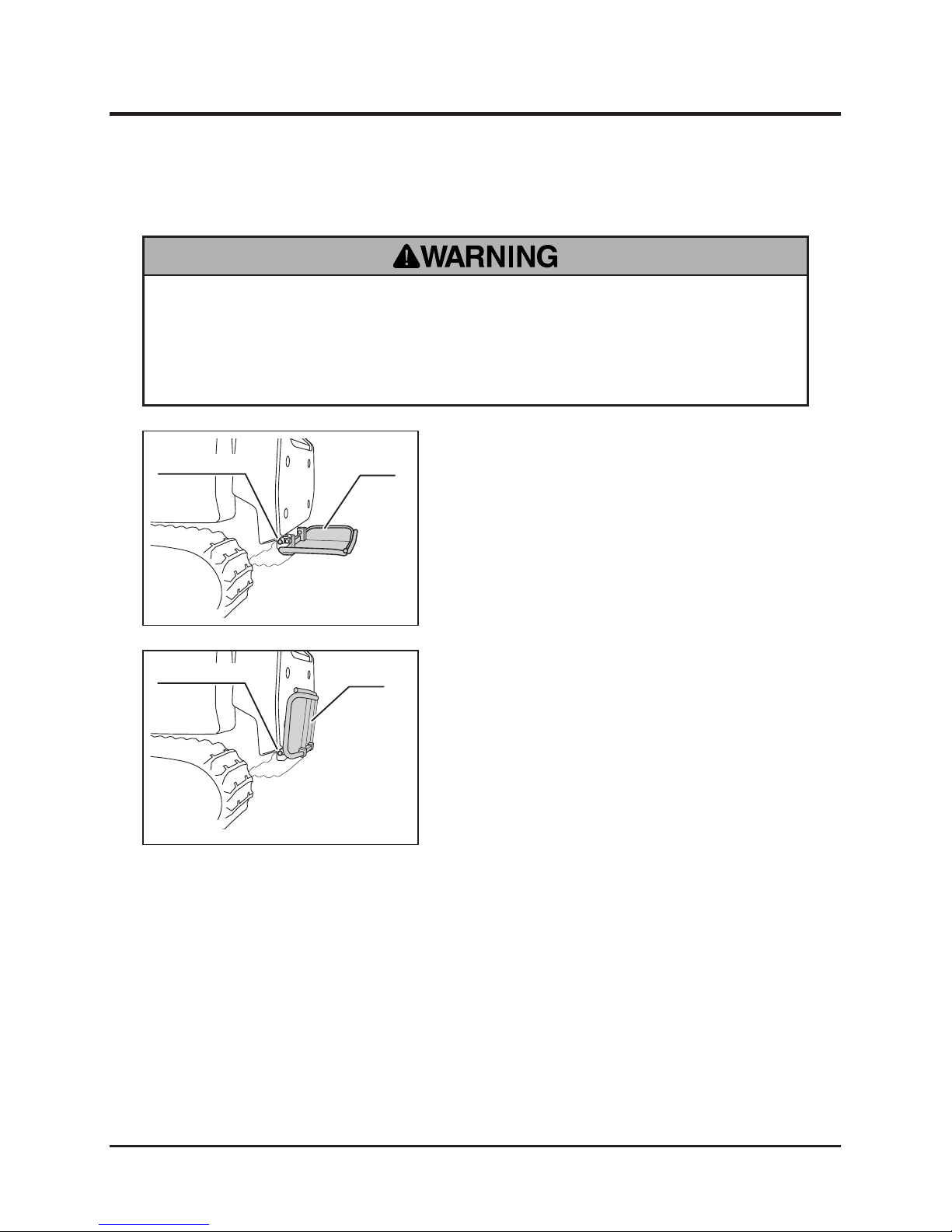
• Hold step rmly when folding or unfolding step. Make certain that hands or
ngers are not in the way to be caught by step when folding or unfolding.
• Make certain that step is securely locked with stopper in either position.
Unfolding/Folding Step
1. Pull stopper knob and fold step.
2. Once step is fully folded, release stopper
knob so that step locks in this position.
Step
Stopper Knob
5116M-0401-040E
1. Hold step rmly and pull stopper knob.
2. Unfold step. Once step is fully unfolded,
release stopper knob so that step locks in
this position.
Step
Stopper Knob
5116M-0401-030E
Folding Step
Unfolding Step
Page 27

Operation
-18-
4
Driving
• Always start and run engine in a well ventilated place.
• Always make certain of the safety of your surroundings when starting engine.
Always unfold step and stand on step when starting engine to avoid accident.
• Do not open engine cover while engine is running. An engine that has been
running is very hot. Avoid touching engine and its ancillaries, or severe burns
may result.
• Always attach string on safety switch to your body so machine stop if you fall
off machine.
• Do not turn main switch to [ (start)] when engine is running. Starter motor
and/or engine may be damaged.
• Do not turn starter for more than 15 seconds. If engine does not start, turn main
switch back to [ (off)] and wait for 30 seconds or more before attempting to
start again.
• Do not use this machine in temperatures above 40ºC (104ºF) or below -15ºC (5
ºF). This machine cannot perform adequately in these temperature ranges.
Using this machine under such conditions may result in an accident or cause
damage to the machine.
• In t he winter o r cold clim ate, warm up engine thoroughly before driving
machine. A cold engine delivers poor performance, which may result in an
accident. It also causes excessive wear.
Starting
Page 28
-19-
Operation 4
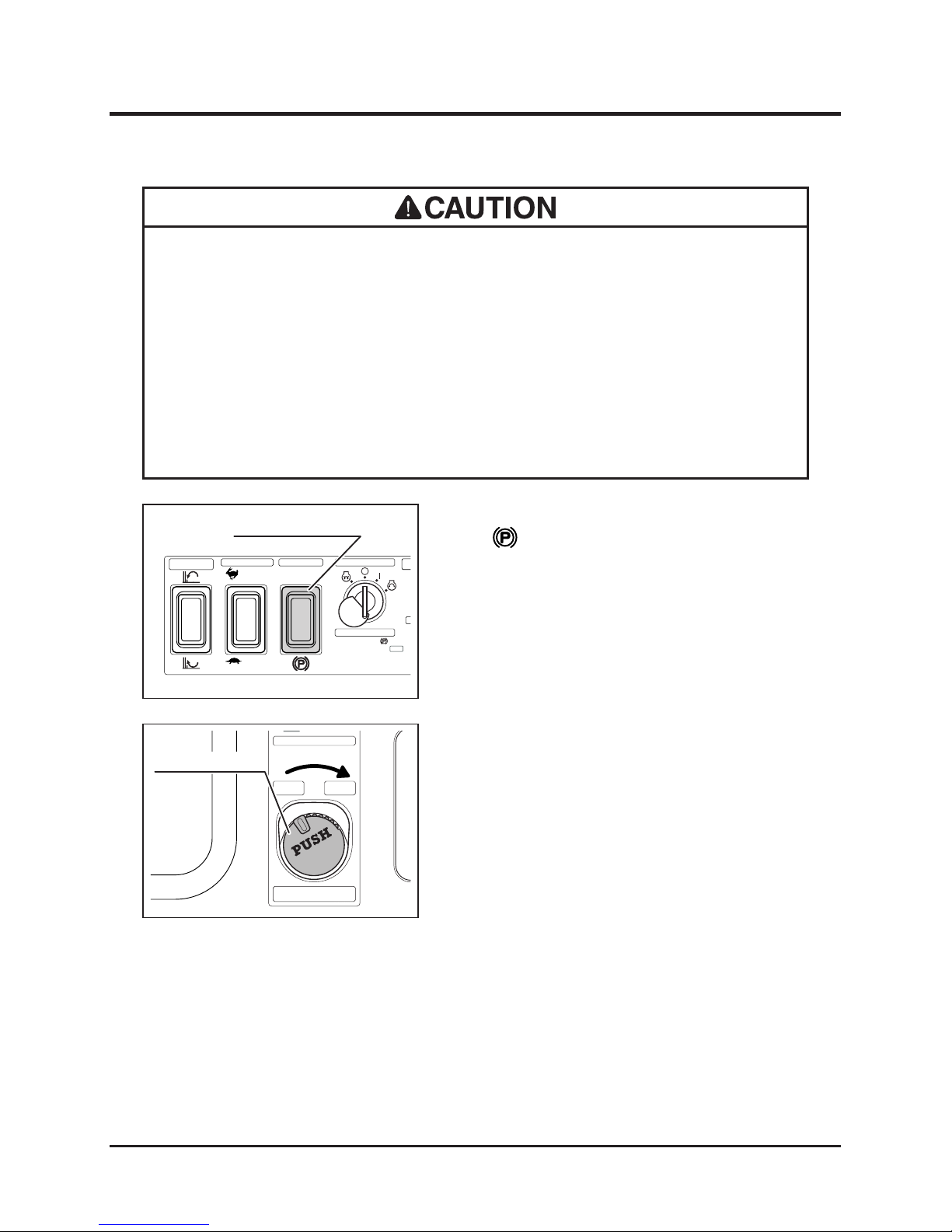
1. Make sure parking brake switch is in
[ (Parking)] position.
2. Make sure implement switc h is i n Stop
position.
Main Switch
Start
Implement
Direction Switch
Im
p
Tr
a
Ce
n
Aux. Transmission
STOP
Reverse
Normal
Parking Brake Switch
5116M-0402-010E
Parking Brake
Drive
1. Parking Brake
2. Imprement Switch
3. Safety Switch "ON"
4. Start Engine
HI
LO
Stop
On
Press and turn
Push to stop
Automatic
Implement Switch
Implement Switch
5116M-0402-021E
• Do not use this product in dusty places such as desert. Dust may clog air
cl e aner or e n ter engin e , which m a y reslt i n loss of p erformanc e and an
accident. It also causes excessive wear.
• Do not use this machine in the altitude above 1500m (4921ft) in its original
conguration. This machine cannot perform adequately above that altitude.
Using this machine under such conditions may result in an accident or cause
damage to the machine. If you need to use this machine above that altitude,
contact your CANYCOM representative.
Page 29
Operation
-20-
4
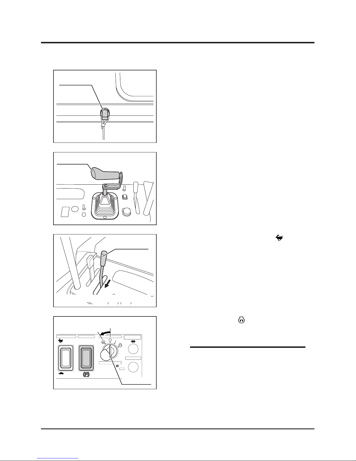
3. Make certain safety switch plug is attached.
Tie its string to your body.
4. Make sure control stick is in neutral position.
Safety Switch
5116M-0402-030E
6. Turn main switch to [ (preheat)] position.
5. Move throttle lever slightly toward [ (fast)].
Control Stick
5116M-0402-040E
• Preheat engine for about 10 seconds when
starting in n o r mal tempera t u r e and for
about 20 to 30 seconds when starting in
cold weather (ambient temperature below
23°F).
• There is no need t o preheat if engine is
already warm.
NOTE
Main Switch
Start
Implement
Translation Switch
Right
Horn
Center
Aux. Transmission
STOP
Preheat
OFF
5116M-0402-060E
Parking Brake
Drive
1. Parking Brake
2. Imprement Switch
3. Safety Switch "ON"
4. Start Engine
HI
LO
Main Switch
(Irrust indicates Hay Collector Model)
Throttle Lever
5116M-0402-051E
Page 30
-21-
Operation 4
• Drive machine gently in the rst 40 to 50
hours of use after purchase for breaking-in.
NOTE
Main Switch
Start
Implement
Translation Switch
Right
Horn
Center
Aux. Transmission
STOP
5116M-0402-070E
Parking Brake
Drive
1. Parking Brake
2. Imprement Switch
3. Safety Switch "ON"
4. Start Engine
HI
LO
Main Switch
ON
Start
OFF
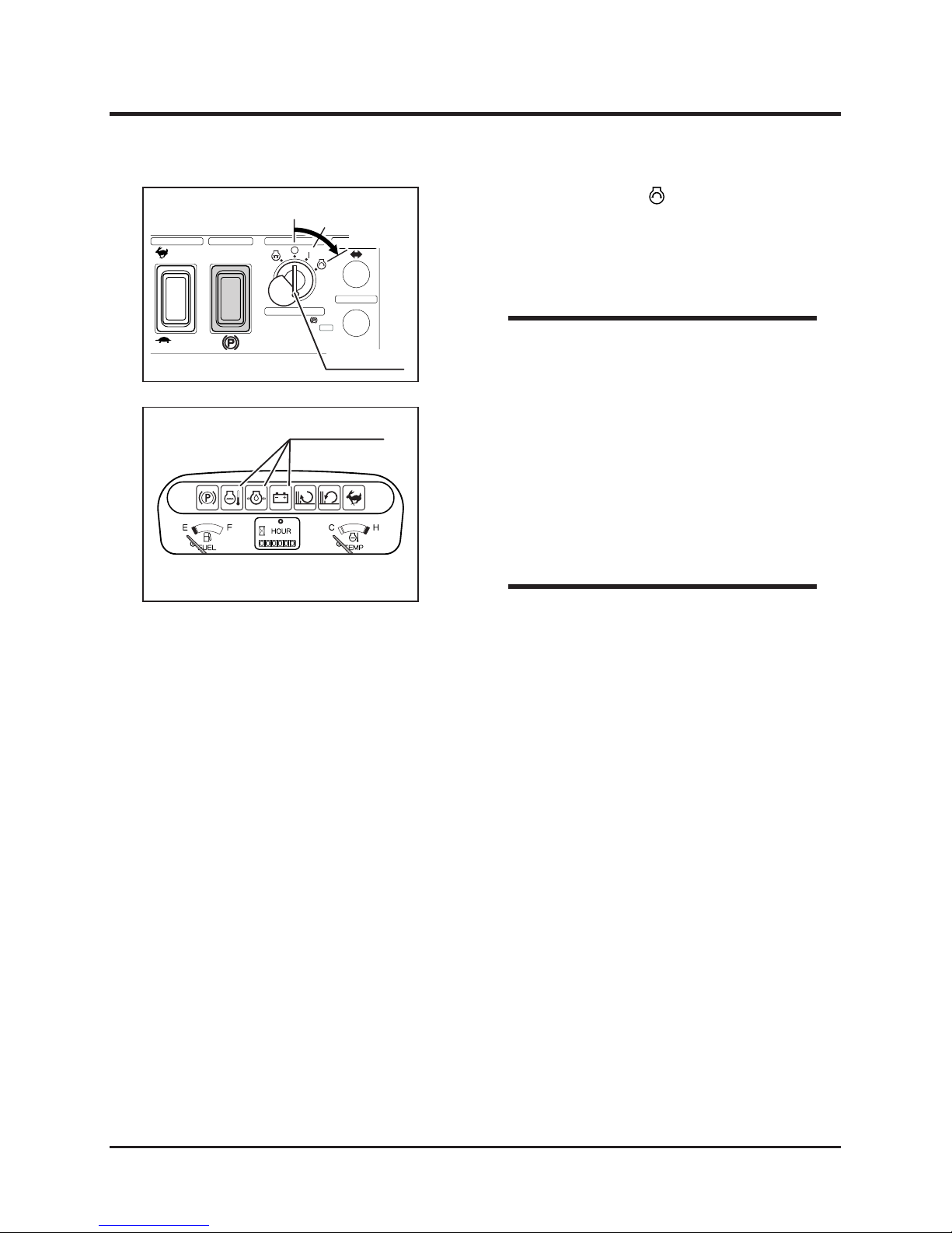
7. Turn main switch to [ (start)] position to
start engine. Once engine starts, release key
immediately; switch will automatically return
to [ | (on)] position.
8. Make certain warning lamps (coolant temp.,
oil pressure, charge lamp) are not lit. If any
of them remain lit, refer to Troubleshooting
(page 71) and take an appropriate measure.
9. Allow engine to warm up by running it for
about 5 minutes without any load.
• Avoid frequent starting. Once engine starts,
run it for a while to charge battery.
NOTE
Warning Lights
5116M-0402-080E
Page 31
Operation
-22-
4
• Do not allow bystanders to come near machine when driving.
• Always make certain of the safety of your surroundings before driving; start
slow.
• Always make certain of the safety of your surroundings before turning.
• Do not make sudden starts, acceralation, change of speed, change of direction,
or stop. Do not t urn a t speed. Avoid sudden maneuvers; this may cause
operator to fall or to be thrown, or machine to tip over.
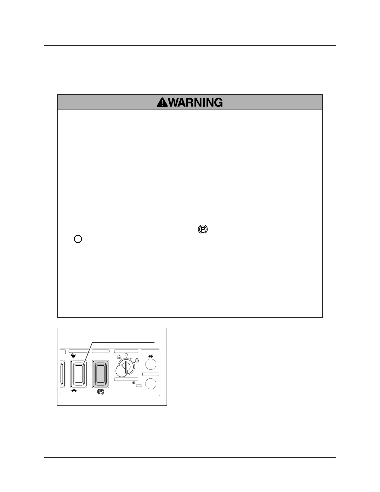
• Do not turn turn parking brake switch to [ (parking)] or turn main switch to
[ (off)] position while traveling. Machine can lose stability and tip over.
• Always stand on step when traveling on machine. Never operate control stick
off of machine. This may cause machine to run over or crush operator.
• Always move the steering levers back to the neutral position before releasing.
Letting it go from other operating positions may result in sudden deceleration
and can cause machine to tip over or operator to fall or to be thrown.
Driving
1. M a k e ce r t a i n o f t h e s a f e t y o f y o u r
surroundings.
2. Set auxiliary transmission switch to a desired
position.
Main Switch
Start
itch
Implement
Translation Switch
Right
Horn
Center
Aux. Transmission
STOP
erse
r
mal
Aux. Transmission Switch
5116M-0402-090E
Parking Brake
Drive
1. Parking Brake
2. Imprement Switch
3. Safety Switch "ON"
4. Start Engine
HI
LO
Page 32
-23-
Operation 4
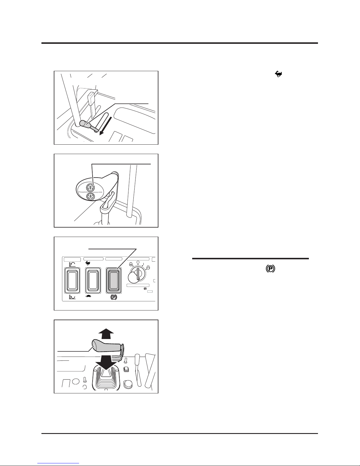
4. Pres s i mplemen t lift swi tch [UP ] t o lift
implement off the ground.
5. Turn parking brake switch to [RUN].
Implement Lift Switch(Up)
5116M-0402-110E
Moving Forward/Backward
3. Move th rot tle lev er tow ard [ (fast) ]
position to increase engine speed.
Main Switch
Start
Implement
Direction Switch
Im
p
Tr
a
Ce
n
Aux. Transmission
STOP
Reverse
Normal
Parking Brake Switch
5116M-0402-010E
Parking Brake
Drive
1. Parking Brake
2. Imprement Switch
3. Safety Switch "ON"
4. Start Engine
HI
LO
6. Move control stick gradually forward to move
machine forward, or move it backward to
travel backward. The angle of control stick
controls the machine speed.
Forward
Backward
Control Stick
5116M-0402-120E
• If parking brake switch is in [ (parking)]
position, machine does n o t m o ve even
when control stick is operated.
NOTE
(Irrust indicates Hay Collector Model)
Throttle Lever
5116M-0402-101E
Page 33
Operation
-24-
4
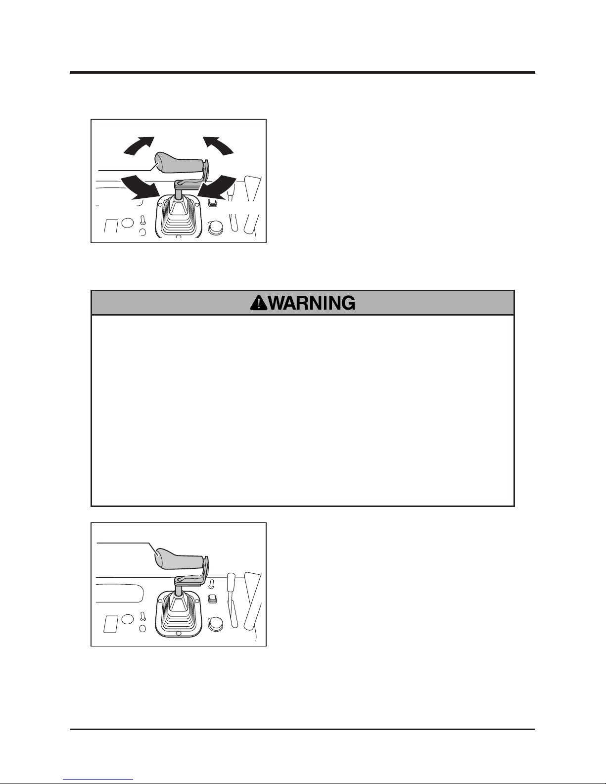
7. Twist control stick gradually to a desired
direction. Machine turns to the corresponding
direction. Turning radius can be controled by
the amount of twisting. Twisting control stick
in the neutral position makes machine spinturn on the spot.
Turning
Right Turn
Left Turn
Left Turn
Right Turn
Control Stick
5116M-0402-130E
• Do not make a sudden stop. Machine may skid or tip over.
• Do not release steering levers suddenly. Machine may stop suddenly and skid
or tip over.
• Always park on a rm, level place. Never park on a potentially dangerous place.
• Avoid parking on a slope. Never park on a slope with an incline of 15 degrees
or steeper. If it is absolutely necessary to park machine on a slope less than 15
degrees, make certain to apply parking brake rmly and block the tracks with
chocks.
Stopping
1. Move control stick gradually to the neutral
position.
Control Stick
5116M-0402-040E
Page 34
-25-
Operation 4
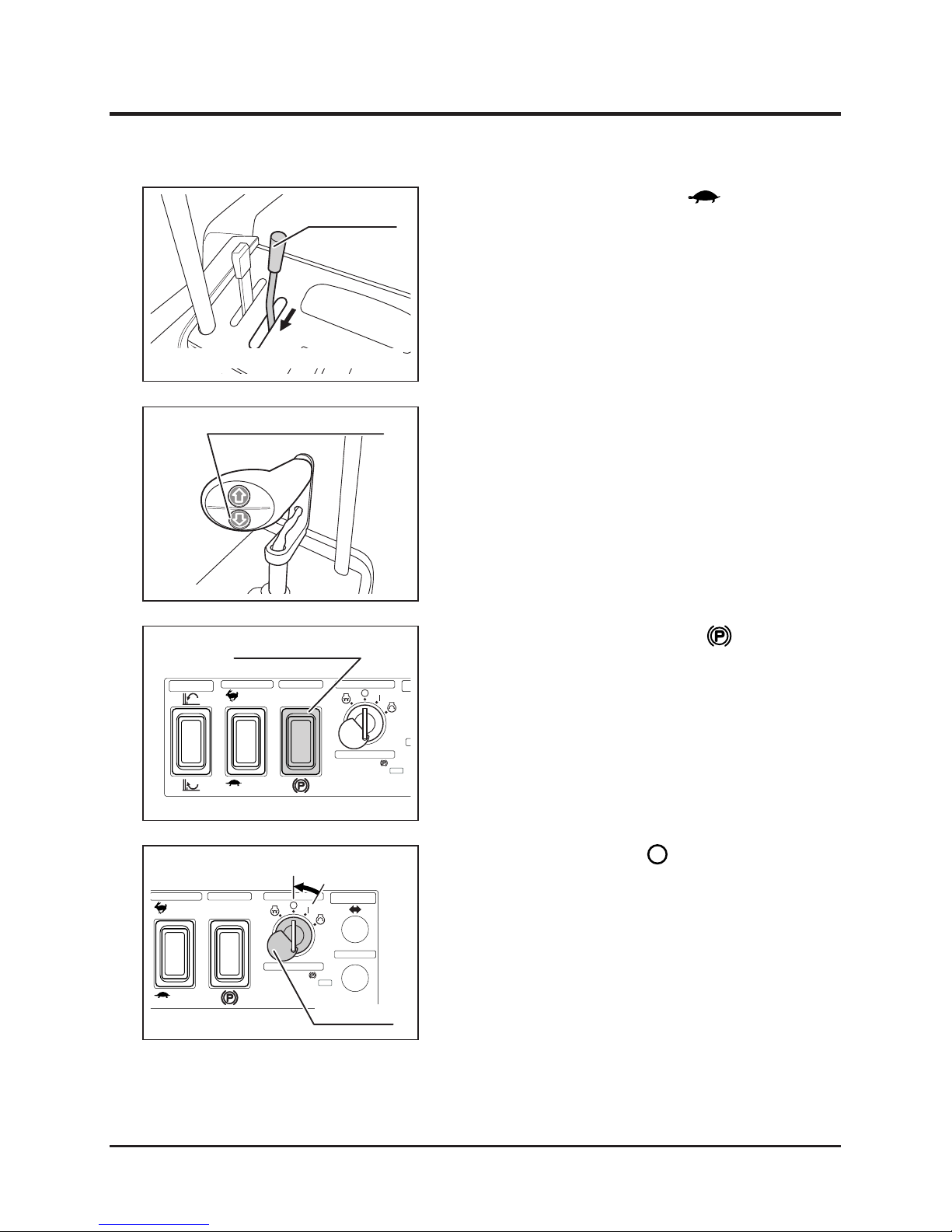
2. Mo ve th ro tt l e le ver t o [ ( sl ow ) ] to
decrease engine speed.
Implement Lift Switch (Down)
5116M-0402-150E
3. Press implement lift switch [DOWN] to lower
implement until it touches the ground.
Main Switch
Start
Implement
Direction Switch
Im
p
Tr
a
Ce
n
Aux. Transmission
STOP
Reverse
Normal
Parking Brake Switch
5116M-0402-010E
Parking Brake
Drive
1. Parking Brake
2. Imprement Switch
3. Safety Switch "ON"
4. Start Engine
HI
LO
4. Turn parking brake switch to [ (parking)]
position.
Main Switch
Start
Implement
Translation Switch
Right
Horn
Center
Aux. Transmission
STOP
1. Parking Brake
2. Imprement Switch
3. Safety Switch "ON"
4. Start Engine
ON
OFF
Main Switch
5116M-0402-160DE
5. Turn main switch to [ (OFF)] position to
stop engine.
6. Remove key.
(Irrust indicates Hay Collector Model)
Throttle Lever
5116M-0402-051E
Page 35
Operation
-26-
4
Working
• Never place any part of body under implement when implement is running. See
implement's manual for safe use.
• Always tie string on safety switch to operator's body so that machine stops
when operator falls off machine.
• Do not allow bystanders to come near machine when working.
• Running implement can throw stones or debris and cause injuries and damages
to nearby people, animals, crops, buildings, automobiles, etc. Pay attention to
the safety of surroundings and plan ahead when working.
• Never attempt to work with implement's shield open (if applicable).
• When working, drive forward. Machine is intended to perform the intended job
while moving forward, and this best prevents stones and debris from being
thrown.
• Turn implement switch to [ON] only when working. Keep it in [OFF] position all
the other times.
• Never attempt to work brush on or near the edge of a ditch or bank. Shoulder of
a ditch or bank may collapse. Pay extra care after heavy rain or earthquake.
• Inspect the work site beforehand; inspect terrain and locate holes, drops, or
obstacles. Also inspect overhead obstacles such as branches of a tree. Pay
special attention when working near these areas.
• On l y sk i ll e d op e ra to r i s a ll o we d t o u se t h is m a ch i n e u n de r d if c u lt
circumstances.
Page 36
-27-
Operation 4
• Do not use this machine on an incline steeper than 30 degres.
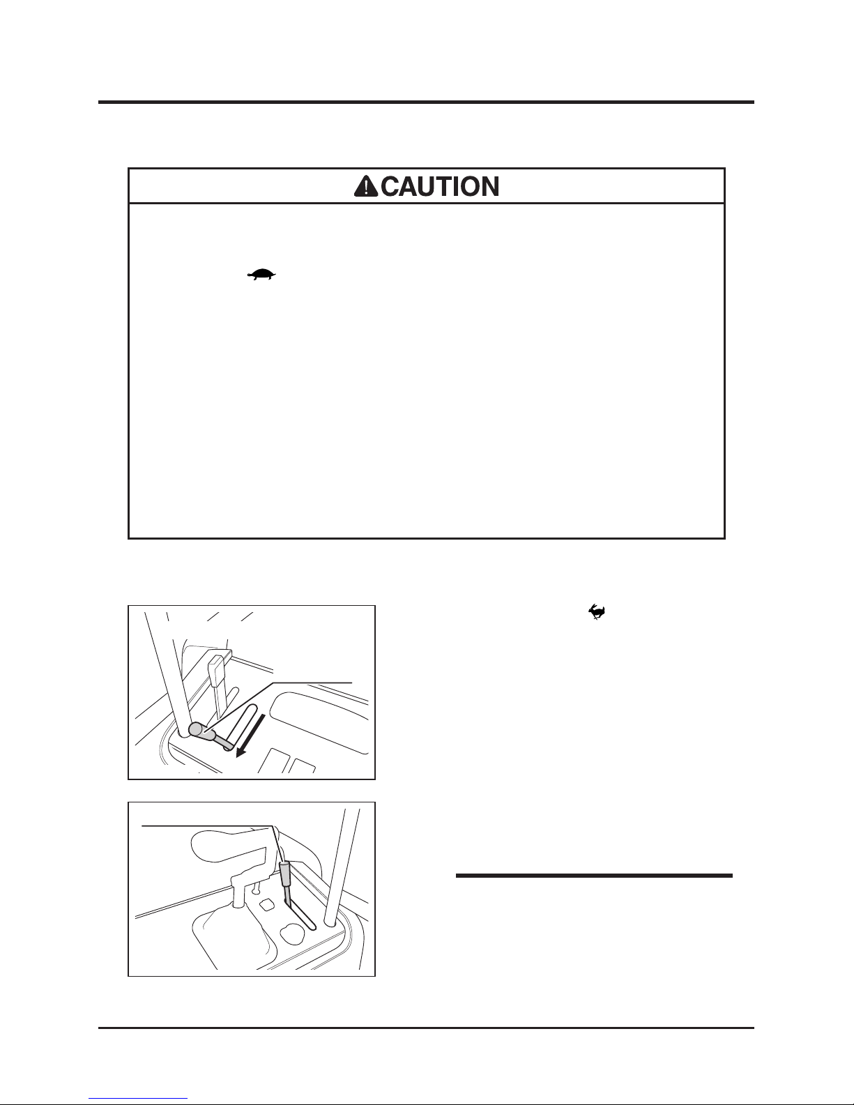
• Always use [ (Slow)] mode when working.
• Do not turn on an incline, or machine can tip over.
• Do not work on a slippery surface.
• When working in a dusty area, clean air cleaner element twice a day. Dirty air
cleaner element results in poor starting, poor performance, or short life.
• When something is tangled to implement, stop engine immediately and remove
the tangled object. Such object causes excessive vibration or load, which
damages machine.
1. Move throttle lever to [ (fast)] position to
increase engine speed.
Operating Implement
(Irrust indicates Hay Collector Model)
Throttle Lever
5116M-0402-101E
2. Use implement height lever to set the desired
cutting height.
Implement Height Lever
5116M-0403-010E
• Implement height lever sets the height to
which implement can be lowered.
NOTE
Page 37
Operation
-28-
4
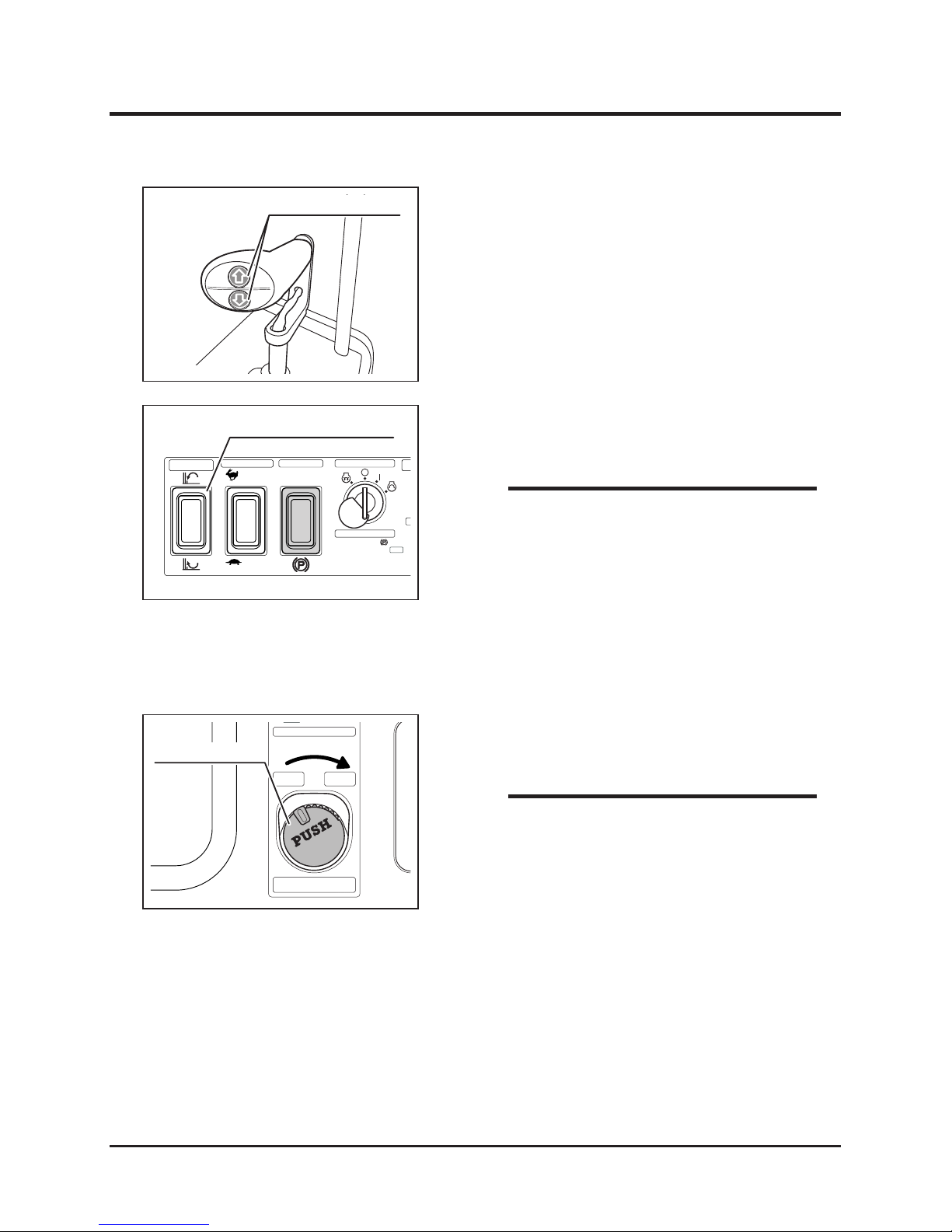
3. Use implem ent l ift s witch to adjus t the
implement height.
Implement Lift Switch
5116M-0403-020E
Main Switch
Start
Implement
Direction Switch
Im
p
Tr
a
Ce
n
Aux. Transmission
STOP
Reverse
Normal
Implement Direction Switch
5116M-0403-030E
Parking Brake
Drive
1. Parking Brake
2. Imprement Switch
3. Safety Switch "ON"
4. Start Engine
HI
LO
• Reverse rotation can be used only when
im plement is not t ranslated to th e side.
If implement i s translated an d r o tation
direction switch is in reverse, implement
stops.
• When something gets tangled to implement,
changing the rotating direction back and
forth may help untangle.
NOTE
4. Use rotation direction switch to choose the
direction of implement rotation.
Stop
On
Press and turn
Push to stop
Automatic
Implement Switch
Implement Switch
5116M-0402-021E
5. Push and turn implement switch to [RUN].
6. Drive machine forward to cut.
• If load is high, reduce traveling speed or
work in stages at different cutting heights.
NOTE
7. To stop implement, press implement switch;
it automatically returns to [stop].
Page 38
-29-
Operation 4
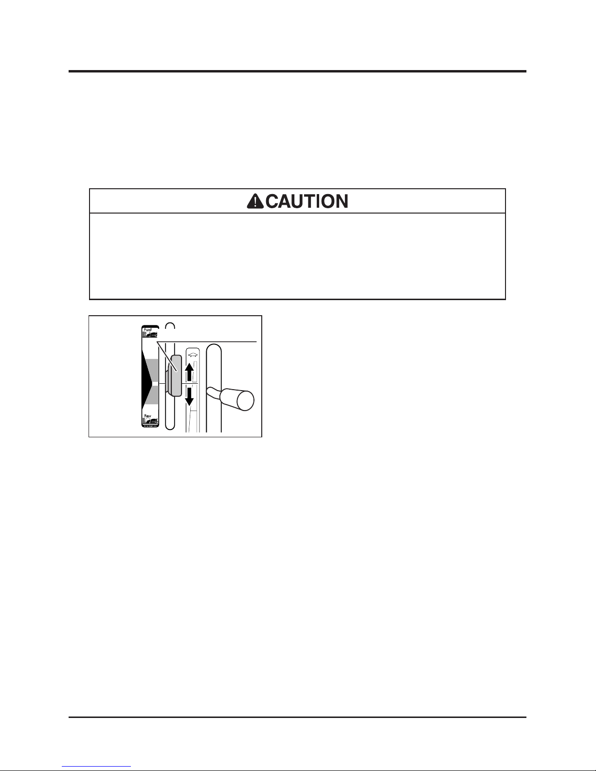
Changing PTO Speed (Variable PTO Speed Model Only)
On Variable Speed PTO model, the PTO speed can be varied to meet requirements for
different implements.
• Use only the implements that are specically designed and certied for this
machine.
• Refer to the instructions for the specic implement.
1. Move throttle lever to adjust engine speed.
2. Move implement direction lever to adjust the
speed and direction of implement.
Reverse
Rotation
Normal
Rotation
Implement Direction Lever
5116M-0403-120E
Page 39
Operation
-30-
4
Main Switch
Start
Implement
Translation Switch
Right
Horn
Center
mission
STOP
O
Left Right
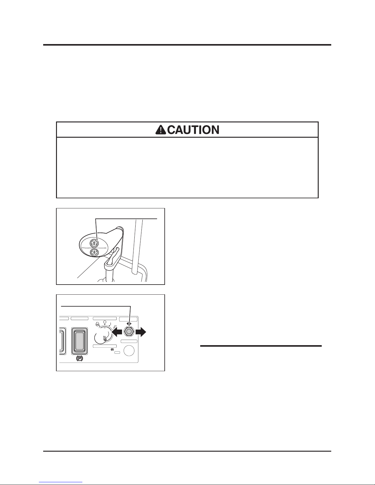
Implement Translation Switch
5116M-0403-040E
Parking Brake
Drive
1. Parking Brake
2. Imprement Switch
3. Safety Switch "ON"
4. Start Engine
2. Tilt implement translation switch to [Right] to
move implement to the right.
3. Tilt translation switch to [Center] to move it
back to the original position.
• Implement does not translate when it is
running.
• When rotating direction is set in reverse,
implement can only translate to about 4 in.
to the right.
• When imp lement is translat ed and t hen
direction switch is set in reverse, implement
does not run.
NOTE
Translating Implement
• Always make certain of the safety of your surroundings before translating
implement.
• Always lift up implement when translating. Translating implement while it is
resting on the ground may cause damage.
With this translation function, the entire implement can be translated to the right by 500mm
at the maximum, allowing working on the edge of ditch or bank.
Implement Lift Switch(Up)
5116M-0402-110E
1. Pres s i mplemen t lift swi tch [UP ] t o lift
implement off the ground.
Page 40
-31-
Operation 4
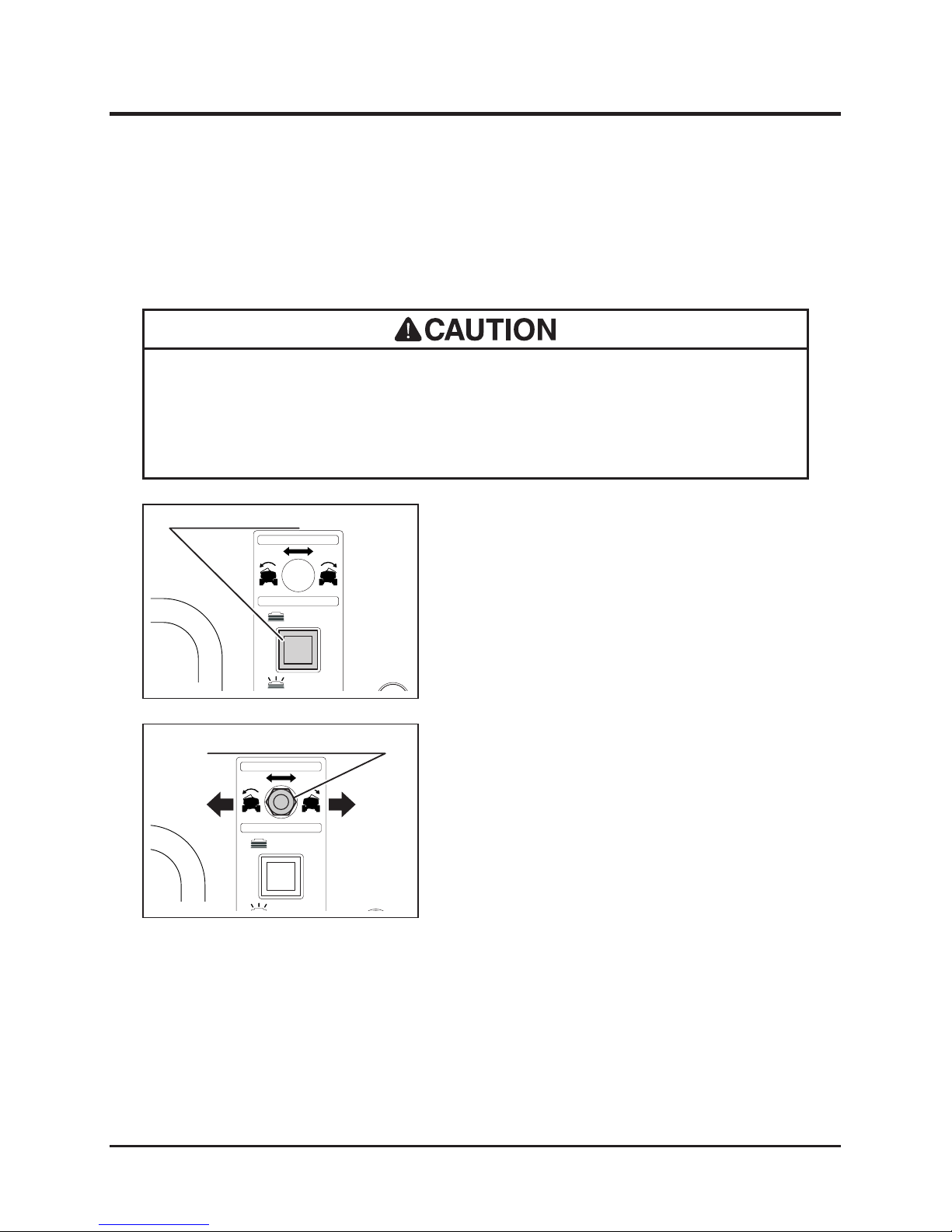
Levelling Step
• Under normal condition, keep step levelling to [AUTO].
• Pinch hazard: beware of pinch spots when levelling step manually. Keep ngers
or hands away of pinch spots.
Step levelling turns step relative to machine to keep it horizontal and provide stable work
platform for the operator.
Left Right
Step Leveling Switch
Black out
Manual
Light on
Automatic
Manual Step Leveling Switch
5116M-0403-050E
Step Leveling Switch
1. Automatic step levelling switch activates or
deactivates automatic step levelling function.
When activated, switch illuminates.
Manual Levelling
2. When automatic levelling is deactivated,
tilting manual leveling switch to the right
turns step to the right (clockwise, as seen
from behind), and tilting it to the left turns
step to the left (counter-clockwise).
Left Right
Step Leveling Switch
Black out
Manual
Light on
Manual Step Leveling Switch
5116M-0403-060E
Manual Step Leveling Switch
Left Right
Page 41
Operation
-32-
4
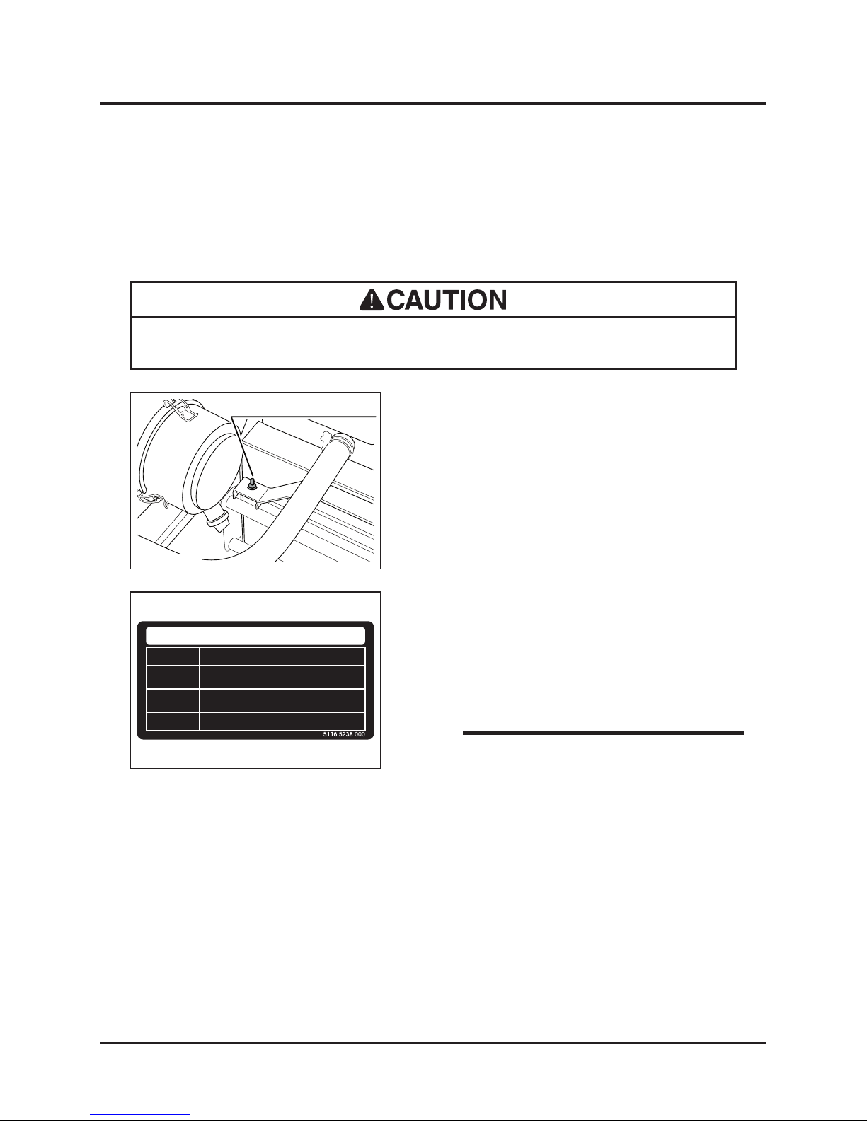
Hydraulic Cooling Fan
• Do not set mode to [1] when working. It may cause overheating.
Hydraulic cooling fan automatically reverses at a certain interval to prevent clogging of
radiator. It has three operation modes to suite different conditions.
Fan Mode Selector Switch
5116M-0403-070E
1. Open top cover and hold it securely with
prop (Page 43).
2. Set fan mode selector switch to select an
appropriate mode for the desired operation.
Cleaning
(Do not use when working)
Normal Use
Working in dusty area
Mode
1
2
3
Usage
5116M-0403-080E
Hydraulic Fan Control Mode Switching
3. Select mode [2] for normal operation.
4. Select mode [3] for working in a dusty area.
5. Select mode [1] when cleaning radiator. Set
switch back to [2] or [3] when cleaning is
done.
• Mode [1] is for blowing off relatively large
debris on site. For small debris in radiator
ns, clean with compressed air regularly.
NOTE
Page 42
-33-
Operation 4
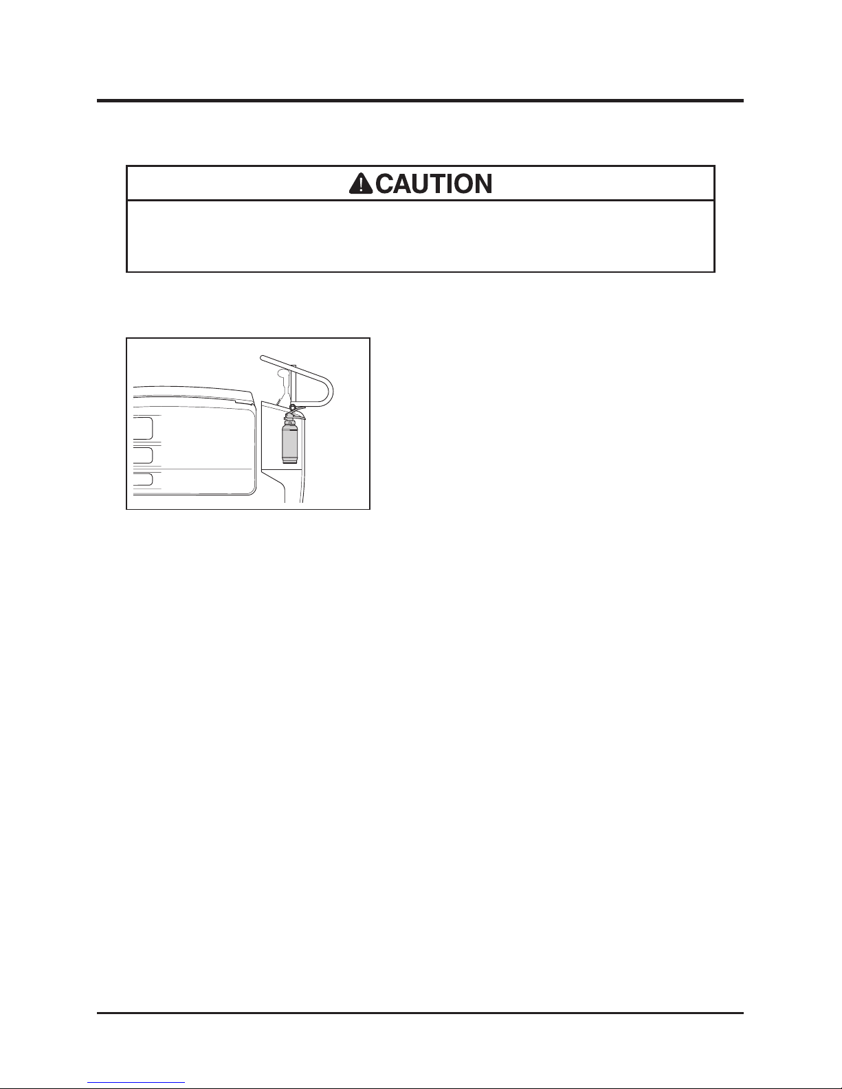
Fire Extinguisher Location
• Read a nd understand the at tached Fire Extinguisher Op erator' s Manual
thoroughly before use.
Refer to the re extinguisher operator's manual for its use.
5116M-0404-010E
1. Fire extinguisher is attached on the left side
of controls cover.
Fire Extinguisher
Using Fire Extinguisher
Page 43
Maintenance
-34-
5
• Follow the scheduled maintenance as described below. Failure to do so may
result in mechanical or property damage, injury or death.
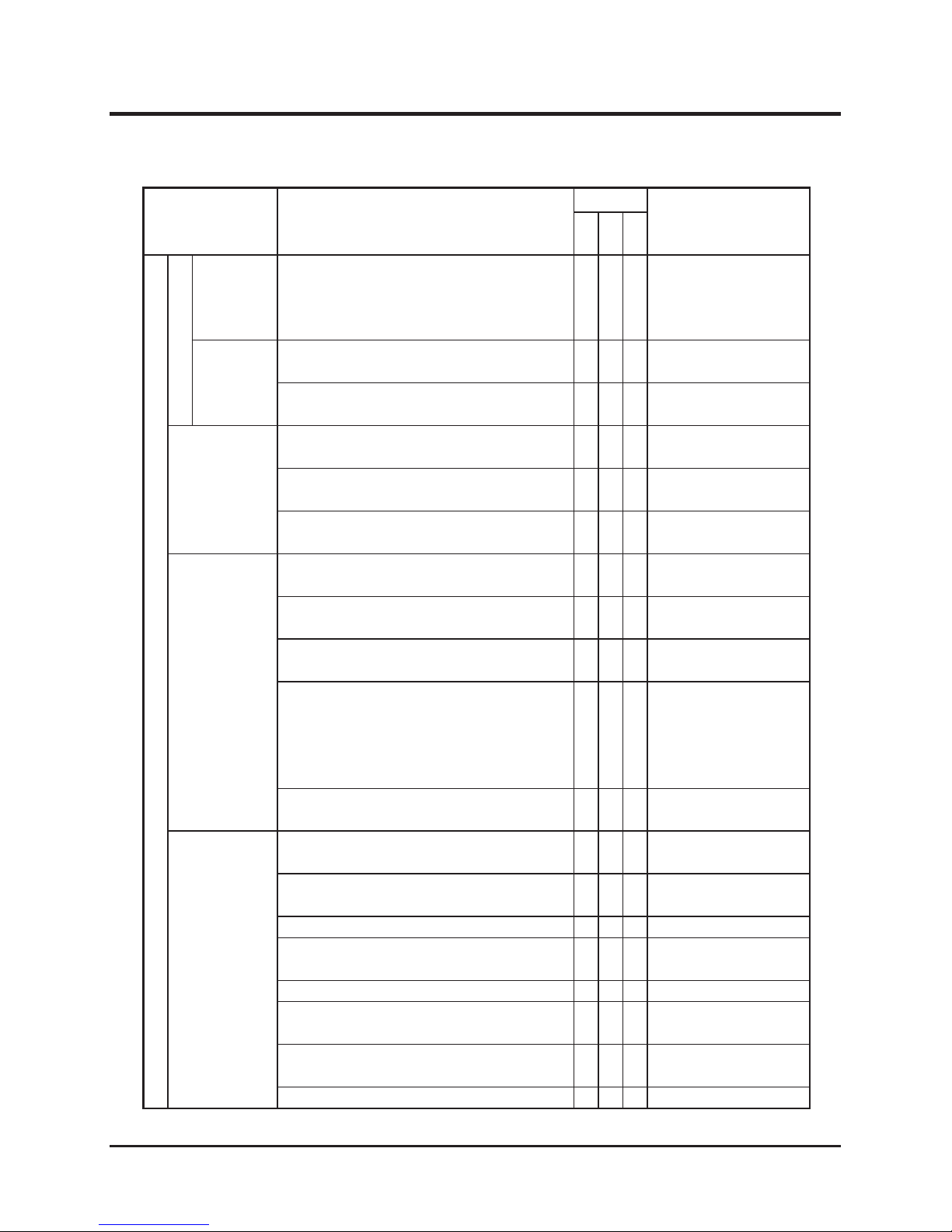
Maintenance Schedule
• Perform a pre-startup inspection (PSI) before each use, a monthly inspection once a
month, and a yearly inspection once a year.
• Some maintenance procedures described below may require special knowledge
or tools and instruments. Contact your CANYCOM representative to perform such
procedures.
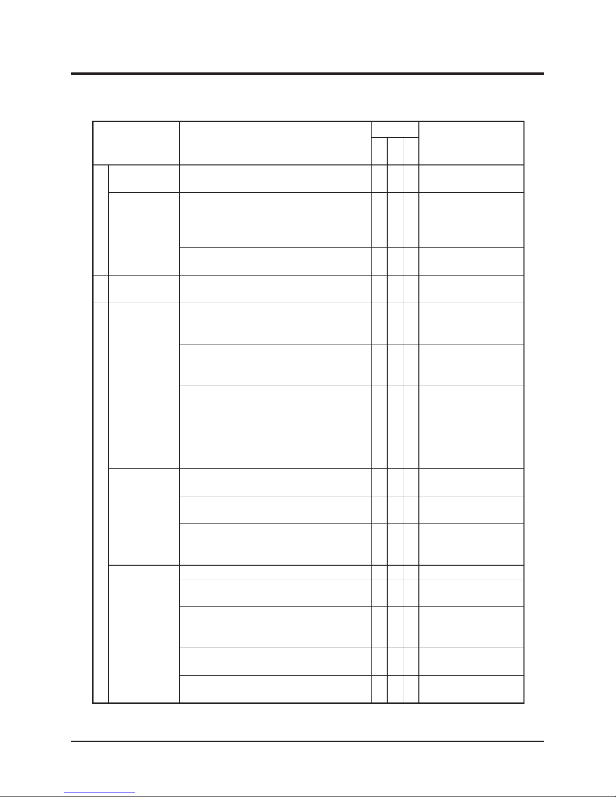
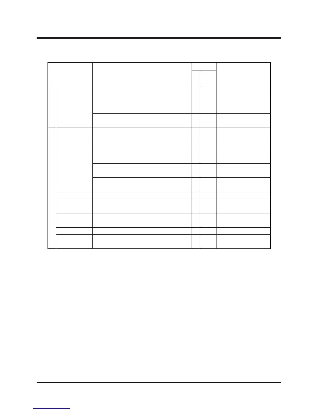
Item Description
Schedule
Note
PSI
Mon
Year
Engine
General
Starting
Engine shall start easily without making any
irregular noise.
√ √ √
Glow plugs work correctly.
√ √ √
Running
Engine speed shall be set properly at idle
and at full without load. Engine shall stay
running smoothly.
√ √
Contact your CANYCOM
representative for
inspection.
When accelerating engine, throttle lever shall
move smoothly, and engine shall accelerate
smoothly without stopping or knocking.
√ √ √
Exhaust
Warm up engine thoroughly, and observe
exhaust sound and gas from idle to fast
speed; exhaust sound shall be normal and
smoke shall not be excessive.
√ √ √
There shall be no leak in exhaust system or
mufer.
√ √
Air
Cleaner
Air cleaner case shall not be deformed or
cracked. Case lid and connecting air hose
shall be rmly in place.
√ √
Cleaner elements shall be in good shape
without damage or excessive dust.
√ √ √
Cleaning/Replacing:
Page 50
Fasteners
Bo lts and nu ts fastening cylinder head,
intake and exhaust manifolds shall be tightly
fastened.
* this may be skipped if there is no gas or
water leaks found in these areas.
√
Page 44
-35-
Maintenance 5
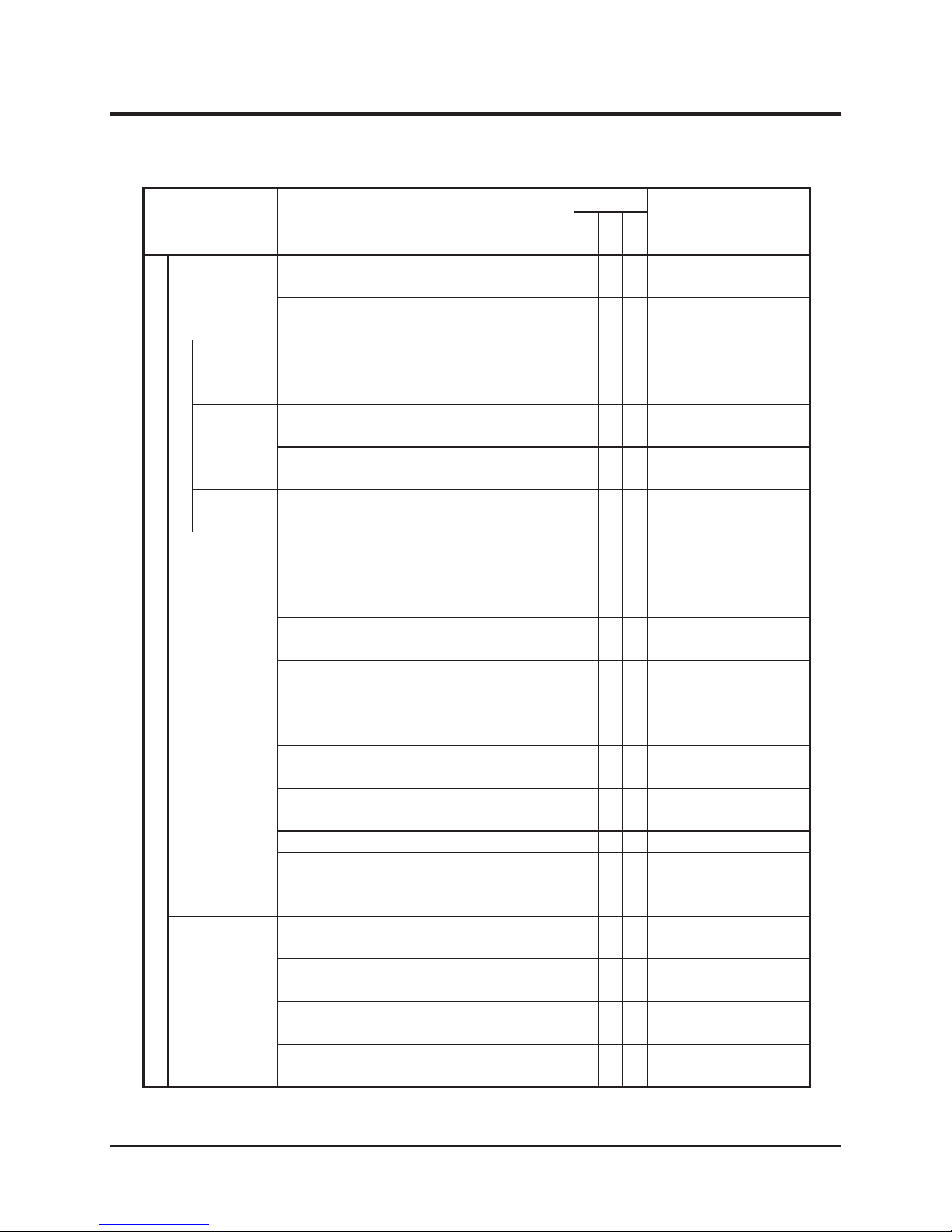
Item Description
Schedule
Note
PSI
Mon
Year
Engine
General
Compression
Compression shall be normal
* this may be skipped if running and exhaust
condition i s n o r m a l at idle and under
acceleration.
√
Contact your CANYCOM
representative for
inspection.
Engine
Mount
Engine base s hall be fr e e of cracks o r
deformation.
√
Mounting bolts and nuts shall not be loose or
missing.
√
Lubrication
System
Oil shall be clean and at correct level.
√ √ √
Inspecting/Changing:
Page 45
No noticable oil leaks shall be found in head
cover, oil pan, or pipes.
√ √ √
Oil lter shall not be excessively dirty or
damaged
√
Changing: Page 45
Fuel System
There shall not be any leaks in fuel tank,
injection pump, hoses, or pipes.
√ √ √
Fuel hose s shall be f r ee of dam a g e or
deterioration.
√ √ √
Fuel lter shall not be excessively dirty or
clogged.
√ √
Cleaning: Page 53
Injection puressure and injection condition
from the nozzle shall be normal.
* this may be skipped if running and exhaust
con dit ion is no rma l a t i dle an d u nd e r
acceleration.
√
Contact your CANYCOM
representative for
inspection.
There shall not be sediment or water in fuel
tank.
√ √
Cleaning: Page 52
Cooling
System
Coolant shall be clean and at the correct
level.
√ √ √
Inspecting/Filling:
Page 47
There shall not be any leaks from radiator,
engine, water pump, or hoses.
√ √ √
Radiator ns shall be free of clogging.
√ √ √
H o s e s s ha l l be f r e e o f d am a g e or
deterioration.
√ √ √
Radiator cap valve shall function properly.
√
Valve seat of radiator cap shall be free of
damage.
√
Fan belt shall be properly tensioned.
√
Inspecting/Adjusting:
Page 51
Fan belt shall be free of wear and damage.
√
Page 45
Maintenance
-36-
5
Item Description
Schedule
Note
PSI
Mon
Year
Engine
Cooling
System
Cooling fan, duct, and cover shall be free of
cracks, damage, or deformation.
√
Mounting bolts and nuts on cooling fan, duct,
and covers shall not be loose or missing.
√
Electrical System
Charge
System
Charge system is working correctly.
√
Contact your CANYCOM
representative for
inspection.
Battery
Battery electrolyte level shall be correct.
√ √
Inspecting/Filling:
Page 62
Terminals shall be free of marked corrosion
and are tightly secured.
√ √
Wiring
Connections shall be securely connected.
√ √
Wiring shall be free of damages.
√ √
Drive Train
HST Pump
Drive the machine forward and backward,
turn left and right in both directions; machine
shall move normally and free of irregular
noise or overheating.
√ √ √
Hydraulic uid shall be lled to a proper
level, clean and free of dirt or contamination.
√ √ √
Inspecting/Changing:
Page 54
There shall be no uid leaks in or around
uid tank.
√
Undercarriage
Wheels
Sprockets
Idlers
Sh all be free of cr acks, defromation, or
excessive wear.
√ √ √
Irregular noise or overheating shall not be
observed from axles when traveling.
√ √ √
Mounting bolt or nut shall not be loose or
missing.
√ √ √
There shall be no oil leak in or around axle.
√ √ √
Roller swings shall follow terrain smoothly
when running.
√
Shall be sufciently lubricated.
√ √
Lubricating: Page 60
Tracks
Stee l cord shall not be cut o r markedly
damaged.
√ √ √
R u b be r s h a l l n o t be m a r k e d l y c u t,
deteriorated, or worn.
√ √ √
Track core shall not be missing or damaged.
√ √ √
Track shall be properly tensioned; shall not
be too loose or too tight.
√
Adjusting: Page 58
Page 46
-37-
Maintenance 5
Item Description
Schedule
Note
PSI
Mon
Year
Undercarriage
Track
Adjuster
Track adjuster shall work normally when
lled with a proper amount of grease.
√ √
Track Frame
There shall not be cracks , deformation,
damage, or excessive wear on wear parts. In
case of a possible crack, use aw detector to
check.
√ √
Mounting bolts and nuts shall not be loose or
missing.
√ √ √
Brake
Parking Brake
Park i n g brake shall be able t o hold the
machine on a 20-degree slope.
√ √ √
Hydraulic System
Hydraulic
Pump
There shall be no leak in or around joints or
seals between hydraulic pump and pipes or
hoses.
√ √
No irregular vibration, noise, or heat shall
be observed wh en hydrauli c pump is in
operation.
√ √
Amount and pressure of discharge under
loa d shall be wi thin the stan dard range
specied by the manufacturer.
*this may be skipped if irregular vibration,
nois e, o r he at d e scr i bed abo v e i s no t
observed.
√
Plumbing
Plumbing shall be free of cracks, damage,
twists, or deterioration.
√ √ √
There shall be no leaks in pipes, hoses,
joints, or seals.
√ √ √
Plumbing shall be mounted properly, and
fastening bolts and nuts shall not be loose or
missing.
√ √ √
Hydraulic
Cylinders
Shall work smoothly.
√ √ √
There shall be no leaks when extending or
contracting cylinder.
√ √
Extend hydraulic cylinder fully under load
and hold. Stroke shall be within the range
specied by manufacturer.
√
Cylinder tube and rod shall be free of dents,
cracks, bends, or scratches.
√ √
Cyli n d er mounting pins shall b e free of
damage or excessive wear.
√ √ √
Page 47
Maintenance
-38-
5
Item Description
Schedule
Note
PSI
Mon
Year
Hydraulic System
Control Valve
Shall be rmly and properly mounted.
√ √
When a valve is operated, its corresponding
cylinder shall move accordingly. when
√ √
There shall be no leaks in pipes, hoses,
joints, or seals.
√ √
Body, Chassis, Safety Devices
Chassis
Frame
Sh all be free of cr acks, deformation, or
corrosion.
√ √
Fastening bolts or nuts shall not be loose or
missing.
√ √ √
Body Panels
Shall be free of cracks or deformation.
√ √
Doors or lids shall open and close, and lock
shall lock properly.
√ √
Fastening bolts or nuts shall not be loose or
missing.
√ √ √
Step
Shall fold, unfold, and lock properly.
√ √ √
Labels
Warning labels and instruction plates shall
be clean, legible, and free of damage.
√ √ √
Instruments
Instruments shall work properly while engine
is running.
√ √ √
Horn
Horn shall work.
√ √ √
Rotor
Indicator
Rotor indicator shall illuminate when rotor is
running.
√ √ √
Page 48

-39-
Maintenance 5
List of Fluids and Lubricants
Item Schedule Grade Cap.
Fuel As needed. Diesel Fuel
52L
(13.74 US gal)
Engine Oil
Fill
Inspect daily. Fill as needed.
Change
In it ia ll y - Af te r 50 h ou rs o f us e.
Every 200 hours afterwards.
Diesel Engine Oil
API rating: CD or better.
SAE rating: 10W-30
9.7L
(10.25US qt)
HST Fluid (doubles
as hydraulic uid)
Change
Init iall y - Aft er 5 00 h ours of u se.
Every 1000 hours afterwards.
High viscosity index hydraulic
uid, ISO VG46
or Diesel engine Oil
API rating: CD or better.
SAE rating: 10W-30
*When using in cold climate
(below -15°C), use ISO VG32
anti-wear hydraulic uid.
42L
(44.38 US qt)
Drive Motor Lubricant
Change
Initially - After 200 hours.
Every 1000 hours afterwards.
Gear Oil
API rating: GL-4
SAE rating: #90
0.6L
(0.63 US qt)
Grease
Every 100 hours.
Lithium all-purpose grease (NLG
No.2 or equivalent)
-
Engine Coolant
Fill as needed
Change every 300 hours.
Long Life Coolant (LLC) and pure
water Mixture
8.5L
(2.25 US gal,
Not including
reservor)
Battery Electrolyte
Check every 50 hours.
Fill as needed.
Distilled Water
-
Page 49
Maintenance
-40-
5
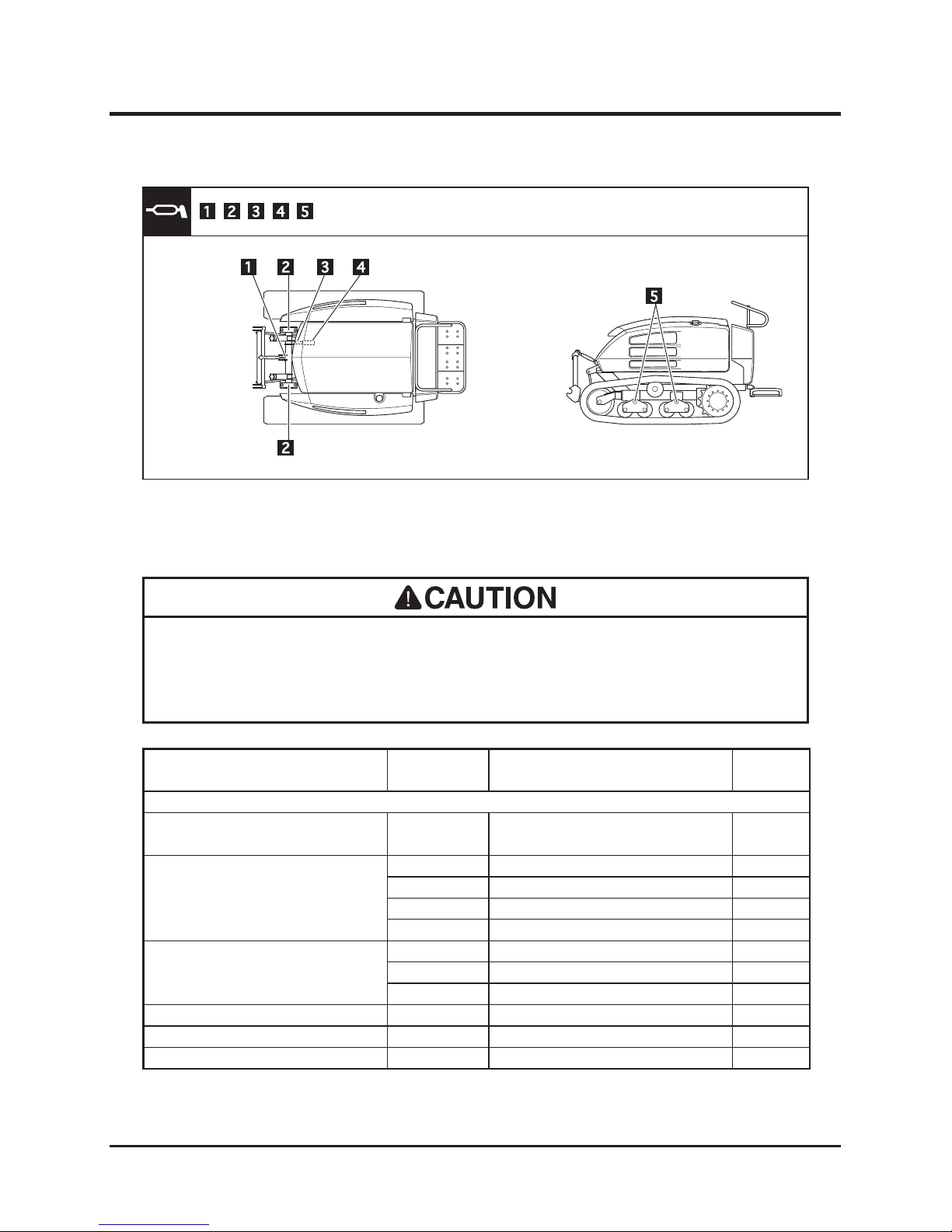
Grease Points
5116M-0502-010E
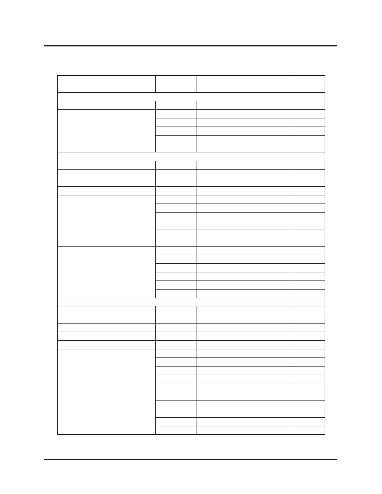
List of Consumables and Spares
• Use only CANYCOM genuine parts when replacement or repair is required.
CANYCOM assumes no liability whatsoever if any problem occurs as a result of
using any part that is not a genuine CANYCOM part.
Item Part No. Schedule Qty.
Engine
Engine Oil Filter Cartridge
36610001300
Every 400 hours (Initially: after 50
hours)
1
Hoses (Raddiator)
51160321001
Every 2 years or if defective. 1
51160325000
Every 2 years or if defective. 1
51160327001
Every 2 years or if defective. 1
51160357000
Every 2 years or if defective. 1
Hoses (Hydraulic Fan)
51166041000
Every 2 years or if defective. 1
51166042000
Every 2 years or if defective. 1
51166043000
Every 2 years or if defective. 1
Air Cleaner Element (Outer)
R1404-42271
Every 1000 hours or if defective. 1
Air Cleaner Element (Inner)
R2401-42281
Every 1000 hours or if defective. 1
V-Belt (Fan)
IG780-97011
If defective.
1
Page 50
-41-
Maintenance 5
Item Part No. Schedule Qty.
Fuel System
Fuel Filter Cartridge
36640221500
Every 500 hours. 1
Hoses (Fuel)
51160531000
Every 2 years or if defective. 1
51160532000
Every 2 years or if defective. 1
51160533000
Every 2 years or if defective. 1
51160534000
Every 2 years or if defective. 1
51160538000
Every 2 years or if defective. 1
Hydraulic System
Suction Filter (Cutting Rotor)
51166453000
Every 1000 hours or if defective. 1
Suction Filter (Gear Pump)
51166454000
Every 1000 hours or if defective. 1
Return Filter Element
51166452100
Every 500 hours or if defective. 1
Hose (Oil Tank)
51166462000
Every 2 years or if defective. 1
Hoses (Lift)
51166223000
Every 2 years or if defective. 1
51166231000
Every 2 years or if defective. 1
51166251000
Every 2 years or if defective. 1
51166252000
Every 2 years or if defective. 1
51166253000
Every 2 years or if defective. 1
51166254000
Every 2 years or if defective. 1
Hoses (Rotor)
51166343000
Every 2 years or if defective. 2
51166344000
Every 2 years or if defective. 1
51166345000
Every 2 years or if defective. 2
51166346000
Every 2 years or if defective. 1
51166347000
Every 2 years or if defective. 1
51166348000
Every 2 years or if defective. 1
Drive Train
Track
51162106000
If defective. 2
Sprocket 15T
36632106000
If defective. 2
Roller
52292201000
If defective. 8
Return Roller Assy
36402218000
If defective. 2
Idler Assy
36402331000
If defective. 2
Hoses (Drive)
51166131000
Every 2 years or if defective. 2
51166132000
Every 2 years or if defective. 2
51166133000
Every 2 years or if defective. 1
51166134000
Every 2 years or if defective. 1
51166135000
Every 2 years or if defective. 1
51166136000
Every 2 years or if defective. 1
51166137000
Every 2 years or if defective. 1
51166138000
Every 2 years or if defective. 1
51166139000
Every 2 years or if defective. 1
51166141000
Every 2 years or if defective. 1
Page 51
Maintenance
-42-
5
• Rubber products such as the hydraulic hose deteriorate over time. Replace them
every 2 years.
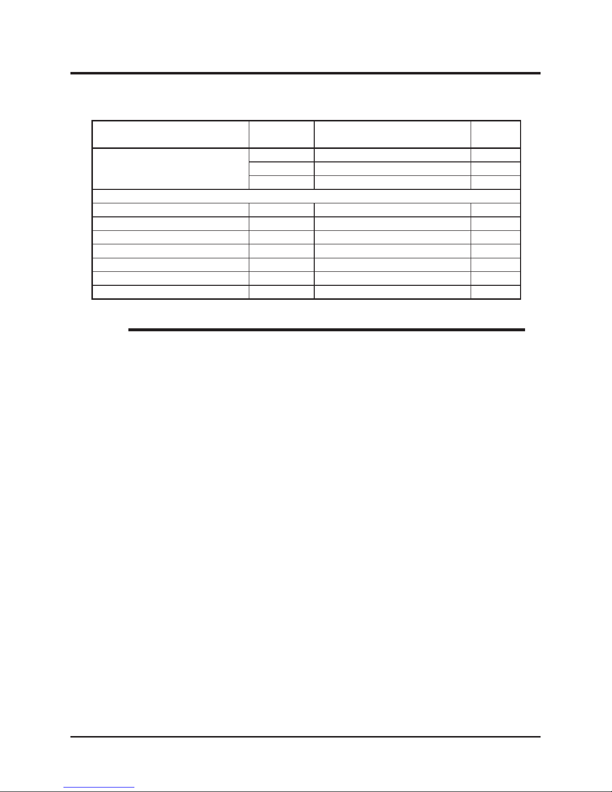
• Track wear limit: 5mm (0.2 in) of lug height
NOTE
Item Part No. Schedule Qty.
Hoses (Drive)
51166142000
Every 2 years or if defective. 1
51166143000
Every 2 years or if defective. 1
51166144000
Every 2 years or if defective. 1
Electric System
Battery 100E41R
36610502000
If defective. 1
Fuse 10A (Red)
09801001004
If defective. 5
Fuse 15A (Blue)
09801001504
If defective. 3
Fuse 20A (Yellow)
09801002003
If defective. 1
Fuse 30A (Green)
09801003003
If defective. 1
Fuse 40A (Green)
09801004003
If defective. 1
Fuse 60A (Yellow)
09801006005
If defective. 2
Page 52
-43-
Maintenance 5
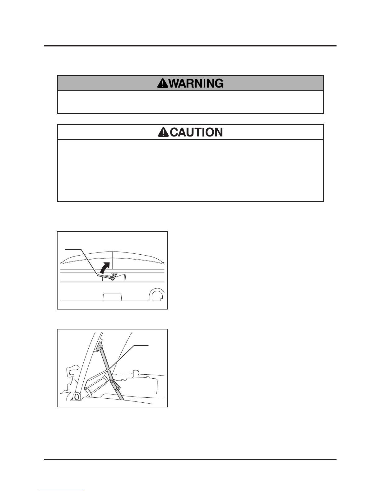
1. Pull up lever to open top cover.
Opening Top Cover
Body Panels
• Cut or pinch hazard exists when removing or installing body panels; beware of
sharp edges and pinch points.
• Make certain to reinstall panels and closing doors after removing or opening for
repairs or inspection.
Lever
5116M-0504-010E
2. Open top cover fully until it stays rmly in
that position with prop.
Prop
5116M-0504-020E
• Do not open engine cover while engine is running.
Page 53
Maintenance
-44-
5
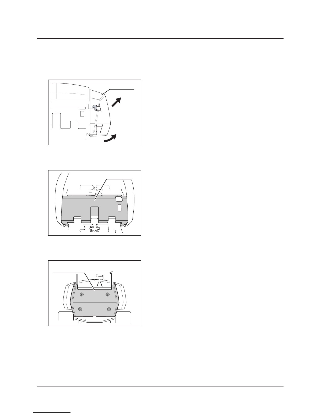
1. Pull lower side of side cover to undo lower
catch.
2. Pull side cover up and away from machine to
undo upper catch.
5116M-0504-030E
Side Cover
Removing Side Covers
Front Cover
5116M-0504-040E
Removing Front Cover
Controls Cover
5116M-0504-050E
Removing Controls Cover
1. Remove side covers on both sides.
2. Undo 6 bolts to remove front cover.
1. Undo 4 bolts
2. Pull controls cover away from machine to
remove.
Page 54
-45-
Maintenance 5
Engine
Engine Oil
• Always stop engine and remove key before servicing.
• An engine that has been running is very hot. Allow engine to cool before
servicing, or severe burns may result.
• Keep re and spark away when handling fuel.
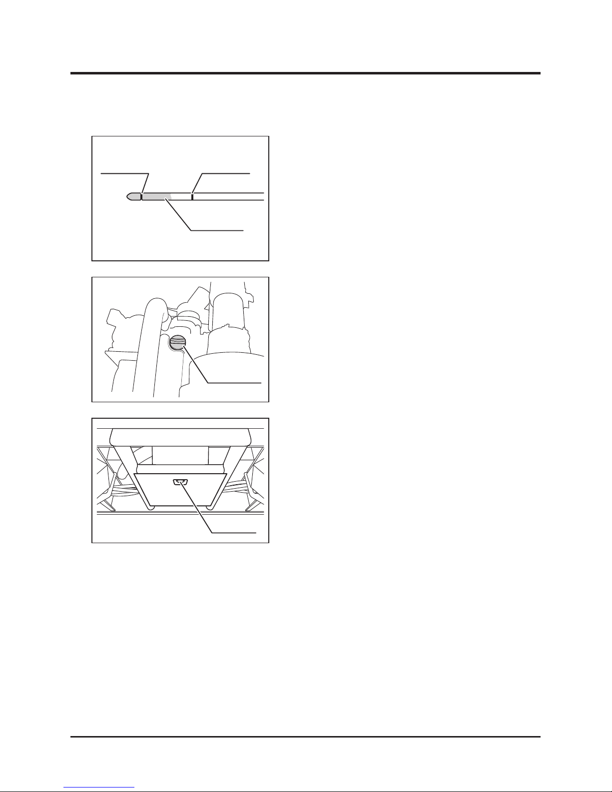
1. Park machine on a level surface.
2. Open top cover and hold it securely in place
with prop.
3. Pull out oil level gauge and wipe off oil. Insert
gauge fully and pull it out again.
• Dispose of drained oil properly.
• Make certain to ll engine with correct grade of oil to the specied level.
Insufcient amount or wrong grade of oil reduces performance and may cause
permanent damage to engine.
Inspecting
Oil Level Gauge
5116M-0505-010E
• To obtain correct reading, check oil level before starting, or wait about 10 minutes
after stopping engine to allow oil to drain back to oil pan.
• Refer also to the Operator's Manual for the Engine when servicing engine.
• Always check oil level on a level surface.
• Oil capacity and grade: Page 39.
NOTE
Page 55
Maintenance
-46-
5
1. Open top cover and hold it securely in place
with prop.
2. Undo and remove oil ller cap.
3. Fill specied oil into ller.
4. Check oil lever.
5. Replace oil ller cap.
6. Close top cover.
Filling
1. Have an appropriate oil drain pan.
2. Open top cover and hold it securely in place
with prop.
3. Remove ller cap.
4. Remove drain plug to drain oil.
5. Clean drain plug and put it back in place and
tighten it securely.
6. Fill oil.
7. Check oil level.
8. Replace ller cap.
9. Close top cover.
Changing
4. Visually check oil level. If it is below lower
limit, ll.
5. Visually inspect the condition of oil. If it is
dirty or its viscousity is not right, change oil.
6. Install oil level gauge.
7. Close top cover.
Level Gauge
Upper LimitLower Limit
5116M-0505-020E
Oil Filler Cap
5116M-0505-030E
Drain Plug
5116M-0505-040E
Page 56
-47-
Maintenance 5
Oil Filter
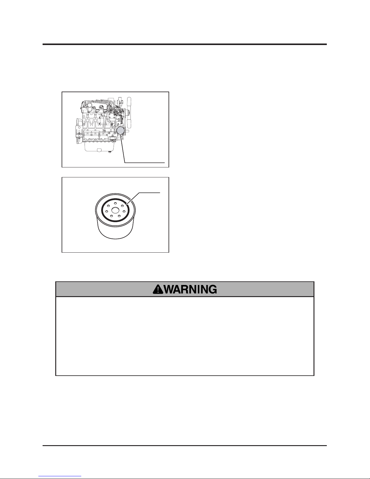
1. Drain oil.
2. Remove oil lter cartridge with lter wrench.
3. Clean lter base on engine.
Oil Filter Cartridge
5116M-0505-050E
Oil Seal
5116M-0505-060E
4. Prepare new lter cartridge. Coat its oil seal
with fresh engine oil.
5. Install cartridge and tighten it fully with hand.
6. Fill oil.
7. Start engine and make sure there is no leak
from lter.
Coolant
• Do not open radiator cap when engine or radiator is hot. Opening cap when
they are still hot may release boiling coolant and cause severe burns. Wait for
engine to cool after operation (about 10 minutes) before opening.
• Take extreme care when handling coolant; antifreeze solution is inammable.
Avoid exposure to open ame. It is also toxic. If coolant is caught in the eye,
wash the eye clean with running water and consult a physician immediately.
Page 57
Maintenance
-48-
5
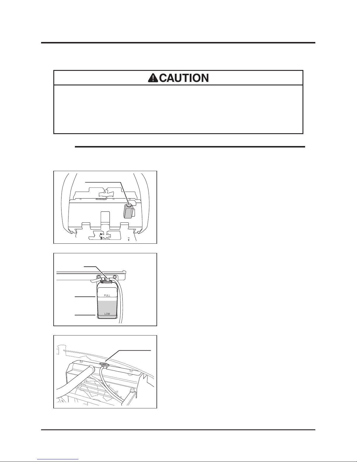
1. Park machine o n a l evel surf ace.Open
engine cover.
2. Visually check en gin e c ool ant le vel in
reservoir tank. Make sure coolant level is
between [LOW] and [FULL] lines.
3. If level is below [LOW] mark, ll water.
Reservoir Tank
5116M-0505-070E
Inspecting
1. Have an appropriate drain pan.
2. Open top cover and hold it securely in place
with prop.
3. Remove radiator cap.
Changing
• Coolant capacity and grade: Page 39.
NOTE
Cap
FULL
LOW
5116M-0505-080E
1. Open top cover and hold it securely in place
with prop.
2. Remove cap and ll coolant to [FULL] line.
3. Replace cap.
4. Close top cover.
Filling
Radiator Cap
5116M-0505-090E
• Maintain sufcient amount of coolant. Insufcient amount of coolant may cause
overheating.
• Dispose of drained coolant properly.
Page 58
-49-
Maintenance 5
When this machine is shipped from the factory,
it is lled with a mixture of 40% antifreeze and
60% water. To prevent coolant from freezing, use
a mixture of water and antifreeze determined by
the minimum temperature in the operation area
using the table on the left.
Antifreeze Mixture (Reference)
Ambient
Temperature
Antifreeze
Mixture
-10 °C (14 °F)
30%
-15 °C (5 °F)
35%
-20 °C (-4 °F)
40%
-25 °C (-13 °F)
45%
* The value for the ambient temperature
is 5°C lower than the actual minimum
temperature.
• Antifreeze to use: Long Life Coolant (LLC).
• Use pure water to make antifreeze mixture.
NOTE
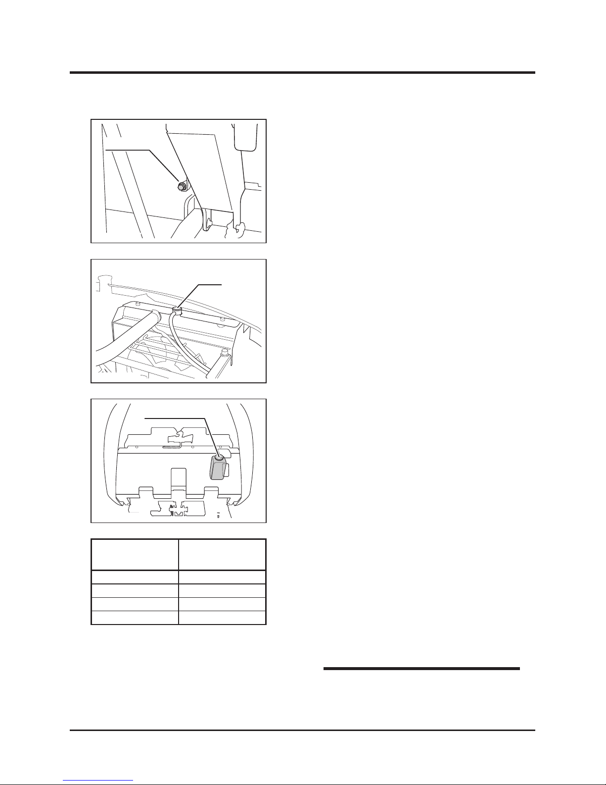
4. Remove drain plug to drain coolant.
5. Wash inside radiator with running water.
6. Replace drain plug.
Drain Plug
5116M-0505-100E
Filler
5116M-0505-110E
Reservoir Tank
5116M-0505-070E
7. Fill coolant into radiator up to ller.
8. Change coolant in reservoir tank.
9. Run engine for 5 minutes to bleed air.
10. Allow engine to cool and open radiator ller
cap and top up with coolant.
11. Replace radiator cap.
12. Close top cover.
Page 59
Maintenance
-50-
5
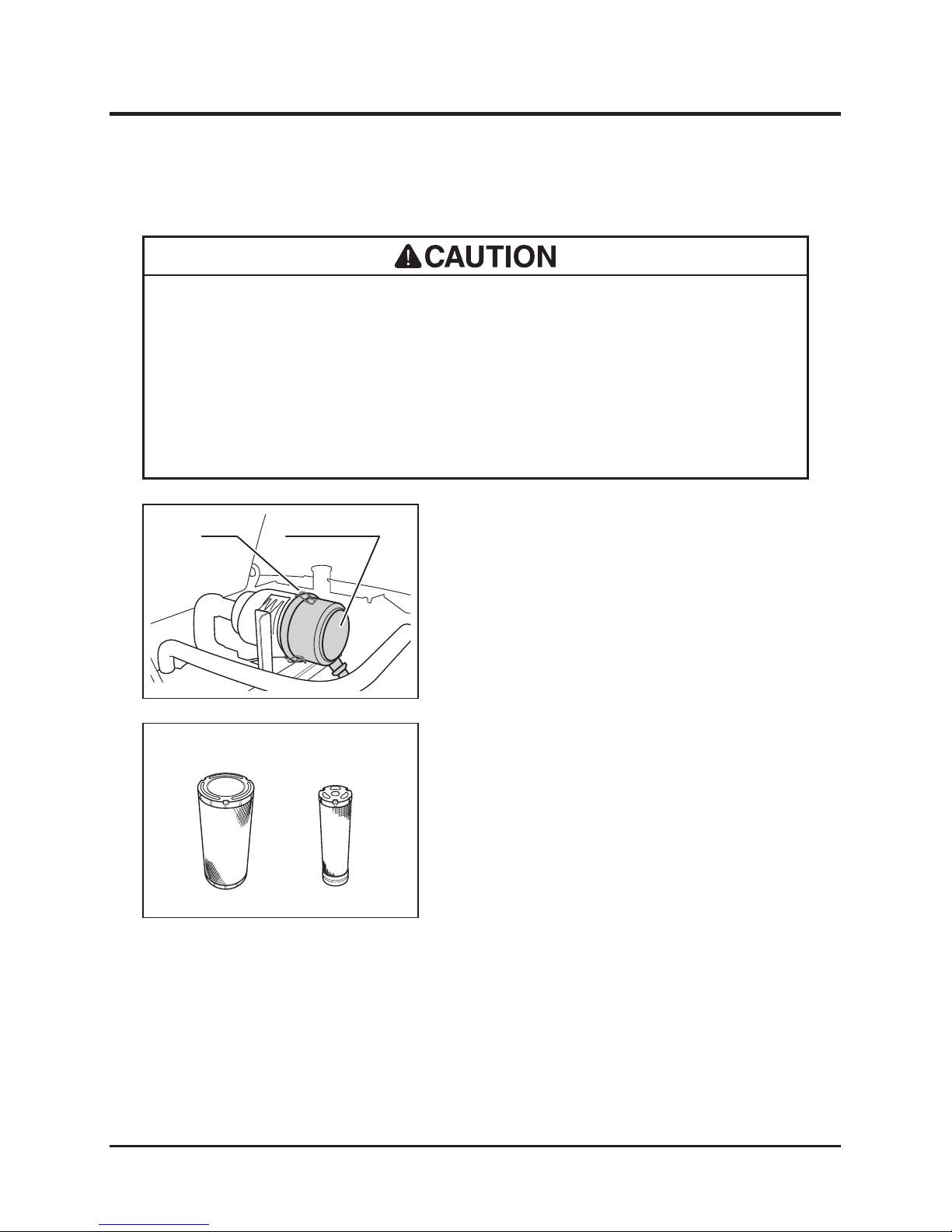
Air Cleaner
• Clean air cleaner element everyday. Dirty cleaner element causes difcult
starting, reduces engine performance and shortens engine life.
• Clean a ir clean er element twic e a day when wor king in extreme ly dusty
environment.
• Replace cleaner element if damaged.
1. Open top cover and hold it securely in place
with prop.
2. Undo locks to remove air cleaner lid.
3. Remove air cleaner elements.
Lock
Air Cleaner Lid
5116M-0505-120E
4. Tap element lightly to dust out. If necessary,
blow compressed air from inside of element
to bloww off dust. If element is extremely
dirty or damaged, replace with a new one.
5. Install air cleaner elements and replace air
cleaner lid. Secure lid with locks.
6. Close top cover.
Outer Element Inner Element
5116M-0505-130E
Page 60
-51-
Maintenance 5
Fan Belt
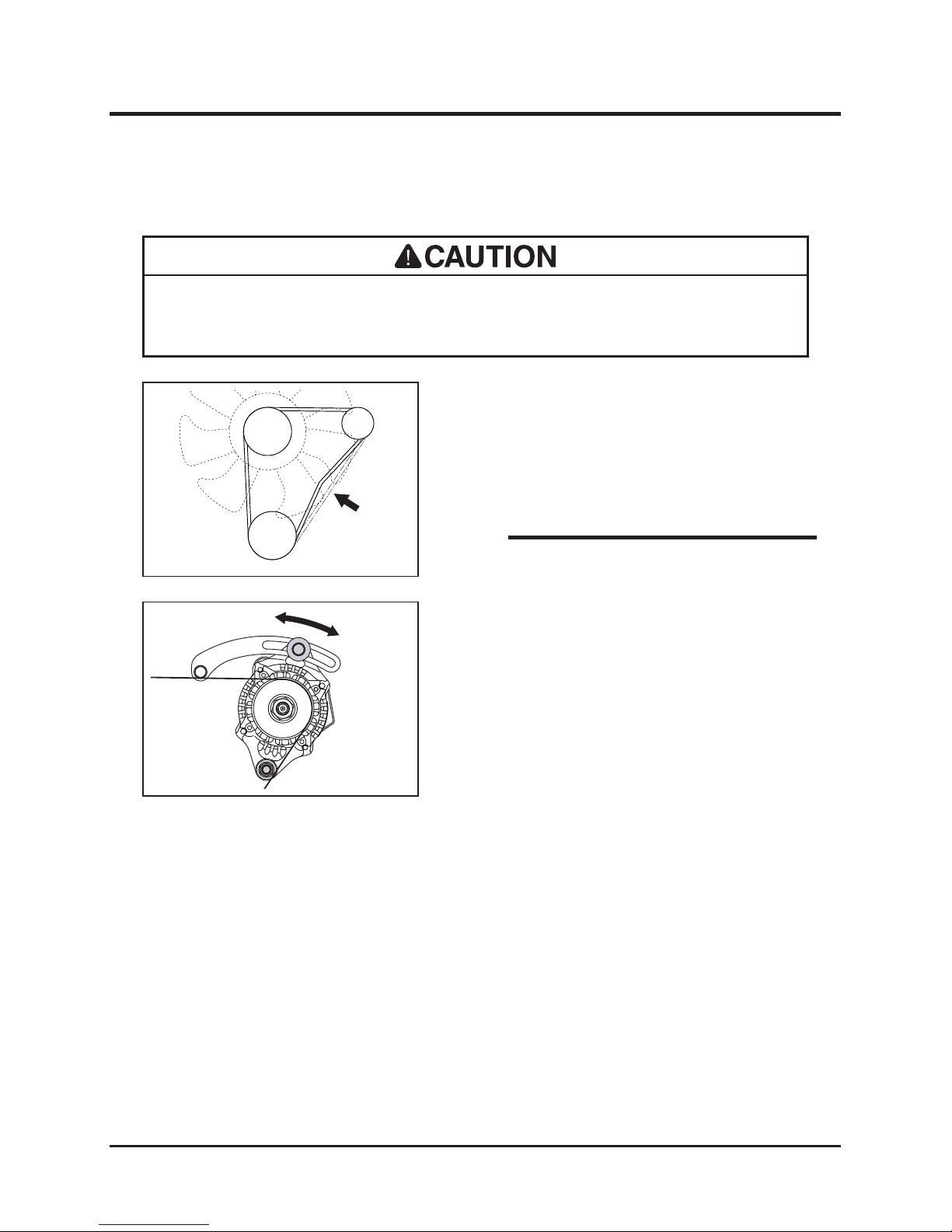
• Adjust fan belt properly. Loose belt slips and reduces cooling airow and
electricity generated by altornator. Slippage also reduces belt life.
1. Open top cover and hold it securely in place
with prop.
2. Push in the middle of belt to check amount of
bending. If it is not correct, adjust.
5116M-0505-140E
1. Loosen bolt that xes alternator.
2. Move altornator to adjust belt tension.
5116M-0505-150E
• Amount of bending: 7mm (0.28in) with 5kgf
(11.0lbf).
NOTE
Inspecting
Adjusting
Page 61
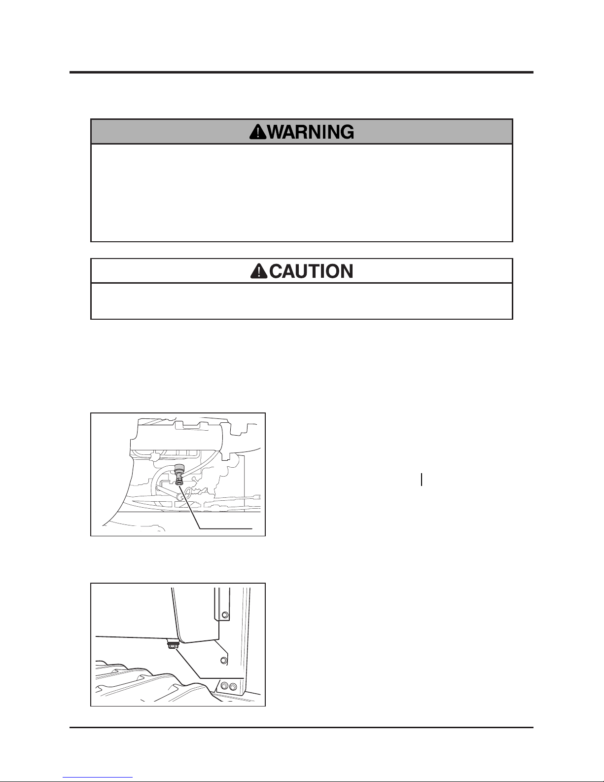
Maintenance
-52-
5
Fuel System
• Stop engine when servicing fuel system.
• Keep re and spark away when handling fuel.
• Do not spill fuel. If case fuel is spilt, wipe out immediately.
Bleeding
1. Fill fuel.
2. Open top cover and hold it securely in place
with prop.
3. Loosen bleeded plug.
4. Turn main switch to [ (ON)] to run fuel
pump for 5 seconds.
5. Tighten bleeder plug.
6. Close top cover.
Bleeder Plug
5116M-0506-010E
When air enters into fuel system after it is completely run dry or fuel lter is replaced, it
becomes impossible to start engine. If that happens, bleed fuel system as follows:
Draining Water
1. Remove left side cover.
2. Remove dra in plu g t o d rai n w ate r a nd
sediment along with remaining fuel.
3. Replace drain plug.
4. Install left side cover.
5. Fill fuel and bleed fuel system.
Drain Plug
5116M-0506-020E
• Dispose of drained uid properly.
Page 62
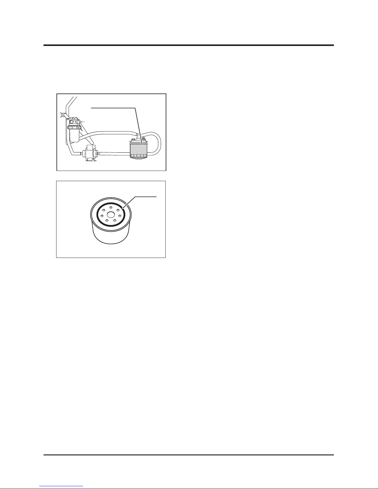
-53-
Maintenance 5
Fuel Filter Cartridge
1. Remove controls cover.
2. Remove fuel lter cartridge with oil lter
wrench.
Fuel Filter Cartridge
5116M-0506-030E
Oil Seal
5116M-0505-060E
3. Prepare new lter cartridge. Coat its oil seal
with fresh fuel.
4. Install cartridge and tighten it fully with hand.
5. Fill fuel and bleed fuel system.
6. Start engine and make sure there is no leak
from lter.
7. Install controls cover.
Page 63
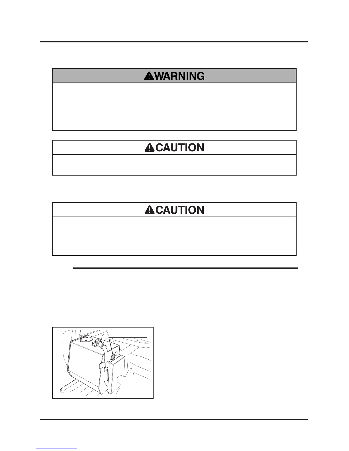
Maintenance
-54-
5
Hydraulic System
• Stop engine when servicing hydraulic system.
• Allow machine to cool off before servicing. Engine is very hot after operation
and may pose a burn hazard.
Hydraulic Fluid
1. Park machine on a level surface.
2. Remove right side cover.
3. Visually inspect uid level and condition in
uid level sight on uid tank.
4. If level is low, ll.
5. If uid is dirty, change.
6. Install right side cover.
Inspecting
Fluid Level Sight
5116M-0507-010E
• Dispose of drained uid properly.
• Maintain sufcient amount of hydraulic uid in hydraulic system. If there is not
sufcient amount of uid, air can enter into circuit, affecting its operation and
reducing efciency.
• To obtain correct reading, check uid level before running engine. Fluid gets hot
and expands after runnining engine.
• Replace suction lters when hydraulic uid is changed.
• Always check oil level on a level surface.
• Fluid capacity and grade: Page 39.
NOTE
Page 64
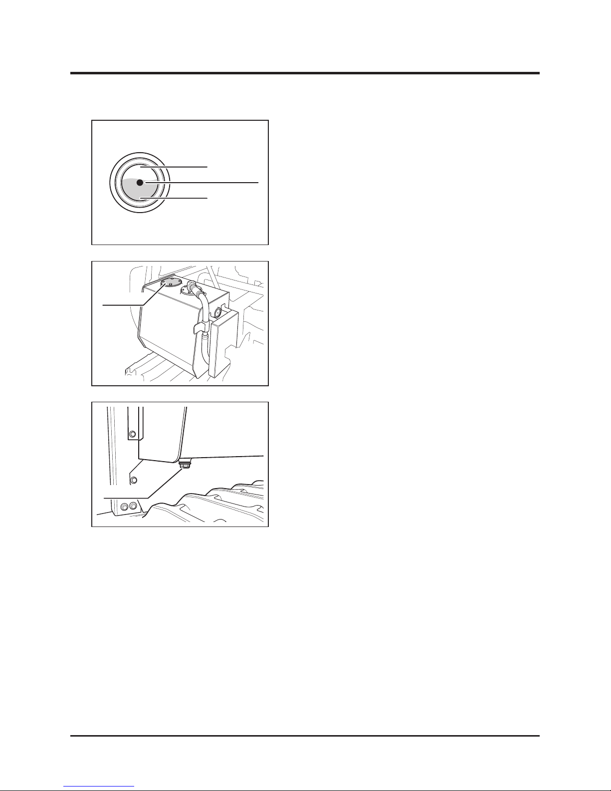
-55-
Maintenance 5
Oil Level Sight Glass
LOW
Recommended Level
HIGH
5116M-0507-020E
1. Remove ller cap.
2. Fill specied uid into ller.
3. Check uid level.
4. Replace ller cap.
Filling
Filler Cap
5116M-0507-030E
1. Have an appropriate drain pan.
2. Remove right side cover.
3. Remove drain plug to drain uid.
4. Replace drain plug.
5. Fill uid.
6. Run engine to bleed air in hydraulic circuit.
7. Check uid level.
8. Install right side cover.
Changing
Drain Plug
5116M-0507-040E
Page 65
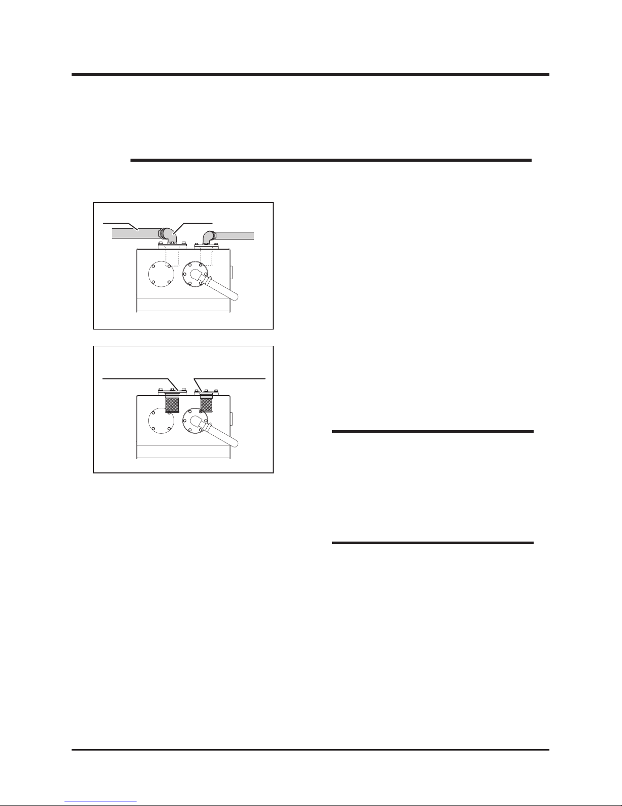
Maintenance
-56-
5
Suction Filter
1. Drain uid.
2. Loosen hose clamp to remove hose from
elbow.
3. Remove elbow.
5116M-0507-050E
ElbowHose
• Replace suction lters when hydraulic uid is changed.
NOTE
Suction Filter
(Cutting Rotor side)
Suction Filter
(Gear Pump side)
5116M-0507-060E
4. Undo mount bolts to remove suction lter
from tank.
5. Install new suction lter.
6. Install elbow.
7. Install hose with hose clamp.
8. Fill uid.
• Wra p seal tap e around t h readed pa r t of
elbow.
NOTE
• Visually check that there is no leak from
hose joints or elbows.
NOTE
Page 66
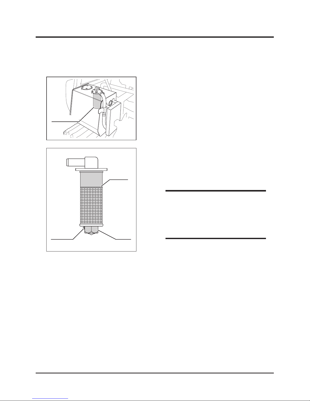
-57-
Maintenance 5
Return Filter Element
1. Loosen hose clamp to remove hose.
2. Undo mount bolts to remove return lter from
tank.
5116M-0507-070E
Return Filter
Element
Set Screw Holder
5116M-0507-080E
3. Loosen set screw and turn holder to remove.
4. Replace element with new one.
5. Replace holder.
6. Tighten set sctew.
7. Install return lter onto tank.
8. Install hoses.
• Tightening Torque: 14.5kgf•cm (1.05ft-lbs).
NOTE
• Make sure there is no leak from hose joints
or elbows.
NOTE
Page 67
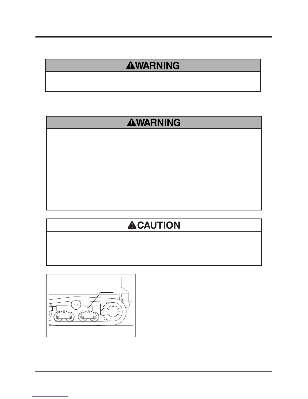
Maintenance
-58-
5
Track
• When jacking up machine, hold machine with jack stands securely. Use jack
stands with sufcient load rating.
• Projection ha z a r d : t r a c k adjuster cylinder is highly pressurized. When
loose n ing v a lve, l o osen g radu a l ly, o r valv e can s h oot o f f. Also a void
positioning your body directly against valve or put your head near it.
• Make certain to adjust track tension properly. Inproperly tensioned tracks may
wear or come off, resulting in property damage, serious injury or death.
1. Park machine on a level surface.
2. Lift one side of track by jacking up or hoisting
machine. Make sure track is parallel to the
ground from the side.
3. Undo 2 bolts to remove adjuster valve cover.
4. Attach grease gun to adjuster valve. Inject
grease to tighten track.
Valve
5116M-0508-010E
Adjusting
• Track stretches during its use-life. Inspect and adjust regularly.
• Track is heavy. Handle with care.
Drive Train
• Stop engine when servicing drive train.
Page 68
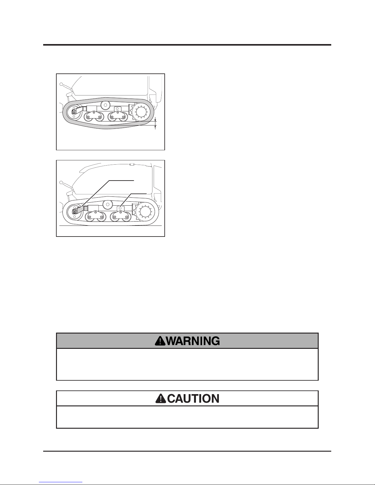
-59-
Maintenance 5
5. Ad ju st t ra ck s o t ha t th e ga p bet we en
track and roller (A) is between 30mm and
40mm (1.18 and 1.57 in) with roller swing
horizontal.
A
5116M-0508-020E
Changing Track
Install track when it derails.
1. Park machine on a level surface.
2. Lift one side of track by jacking up or hoisting
machine.
3. Loosen adjuster valve a little to reduce
pressure inside adjuster cylinder.
4. When sufciently depressurized, remove
valve.
5. Push idler fork in.
6. First put track on the sprocket-side, then put
it around idler.
7. Install valve. Make sure not to jam o-ring.
Tighten it securely.
8. Adjust track tension.
Valve
Idler Fork
5116M-0508-030E
• Allow machine to cool off before servicing. Drive components are very hot after
operation and may pose a burn hazard.
Drive Motor Lubricant
• Dispose of drained uid properly.
Page 69
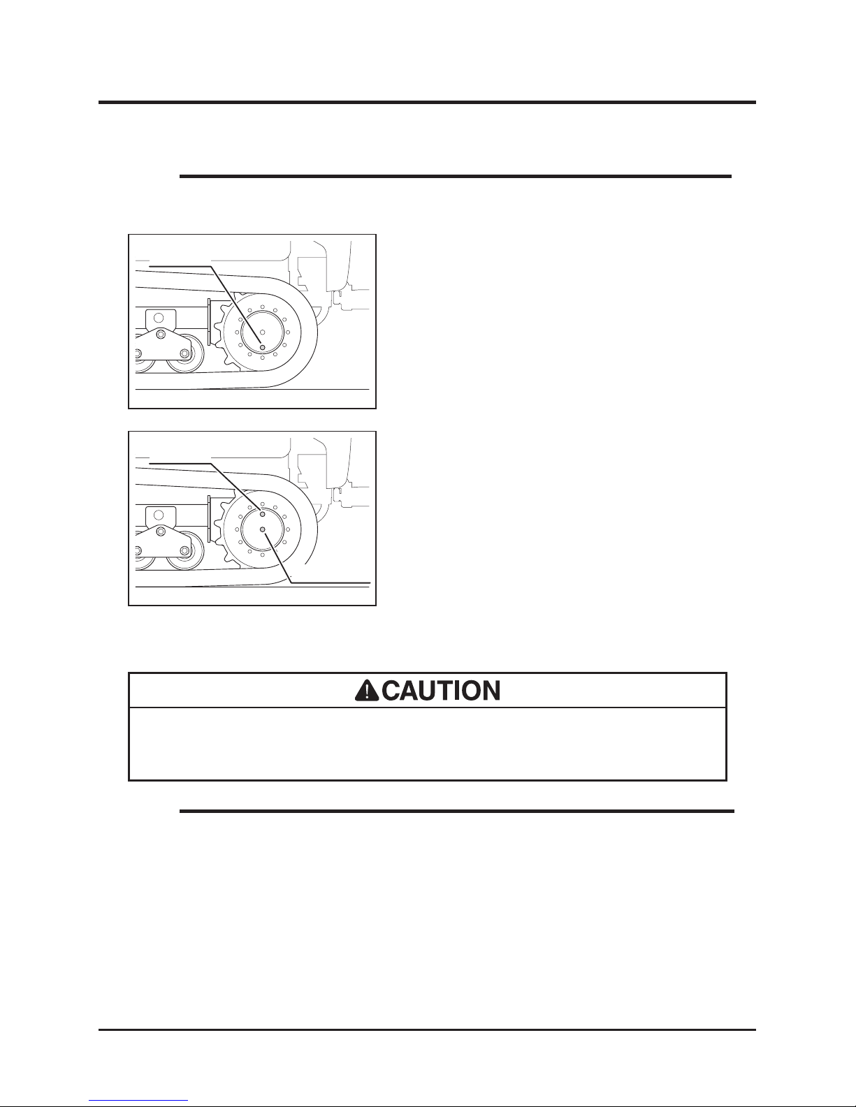
Maintenance
-60-
5
• Fluid capacity and grade: Page 39.
NOTE
1. Park machine so that drain plug on drive
motor is in the lowest position.
2. Have an appropriate drain pan.
3. Remove drain plug to drain lubricant.
Drain Plug
5116M-0508-040E
Drain Plug
5116M-0508-050E
Oil Level Plug
4. Move machine so that drain hole is placed
avobe check plug.
5. Remove check plug.
6. Fill sprcied lubricant into drain hole until it
ows out of check hole.
7. Replace drain and check plugs.
Greasing
• Follow the maintenance schedule to grease up machine. Lack of greasing may
result in rust, excessive wear or seizure.
• When using a manual grease gun, pump 5-6 times. When the handle of the gun
becomes heavy, stop pumping immediately.
• When using a pneumatic grease gun, pump it for a few seconds.
• Grease to use: Page 39
NOTE
Page 70
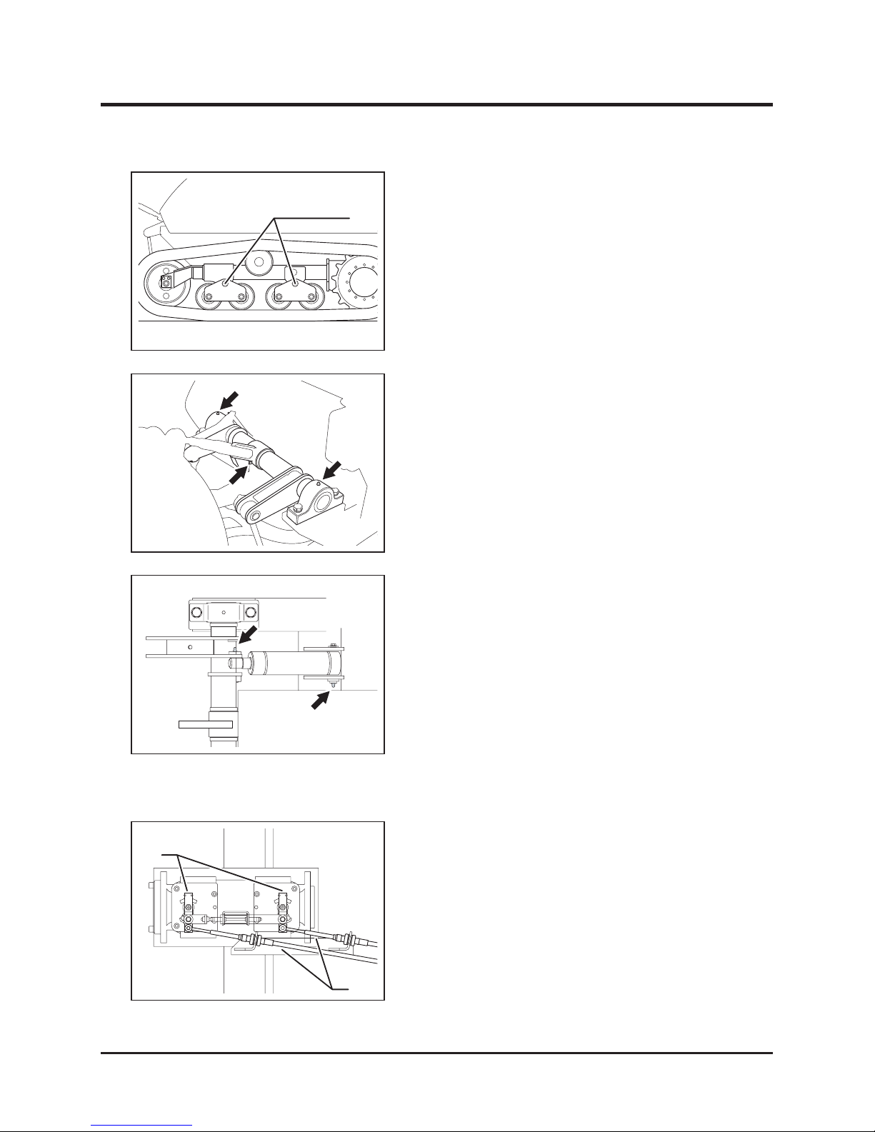
-61-
Maintenance 5
Swing Pivots
5116M-0508-060E
1. Grease roller swing pivots (4 places).
5116M-0510-070E
1. Grease bearings and links on three-point
hitch.
Three-Point Hitch Links and Bearings
5116M-0510-080E
1. Grease pi ns o n th e en ds o f hy dr au li c
cylinder.
Cylinder Pins
Control Stick
A
5116M-0508-070E
C
1. Adjust push-pull wires (C) so that links (B)
is perpendicular when control levers (A) on
HST pumps are in neutral.
Page 71
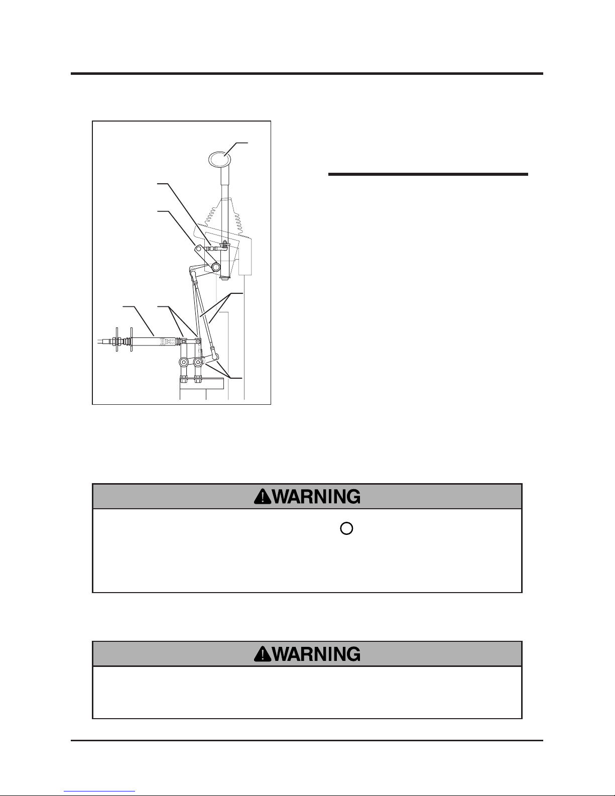
Maintenance
-62-
5
Electrical System
Battery Fluid
• Never use machine when battery uid level is below [Lower Level]. It severely
shortens battery life and can cause battery explosion.
• Always stop engine, turn main switch to [ (OFF)] and remove key when
inspecting or servicing electrical system.
• Shock hazard: never work on electrical system with wet hand.
2. Adjust rods (F) so that links (E) on both ides
are parallel when control stick (D) is vertical.
D
B
G
H
C
E
F
5116M-0508-080E
3. Adjust rods (G) so that links (B) start to move
at the same time when control stick (D) is
tilted forward and backward.
4. Start engine and turn parking brake switch
to [RUN] and observe if machine moves. If
it does, stop engine and adjust again until it
does ot move.
5. Dr i v e m a c h i ne s t r a i g h t for w a r d a n d
backward and observe if machine travels
straight. If it does not, move the location of
link balls in slots (H). Fine-tune with gods
(G).
• Make sure there is no leak from hose joints
or elbows.
NOTE
Page 72
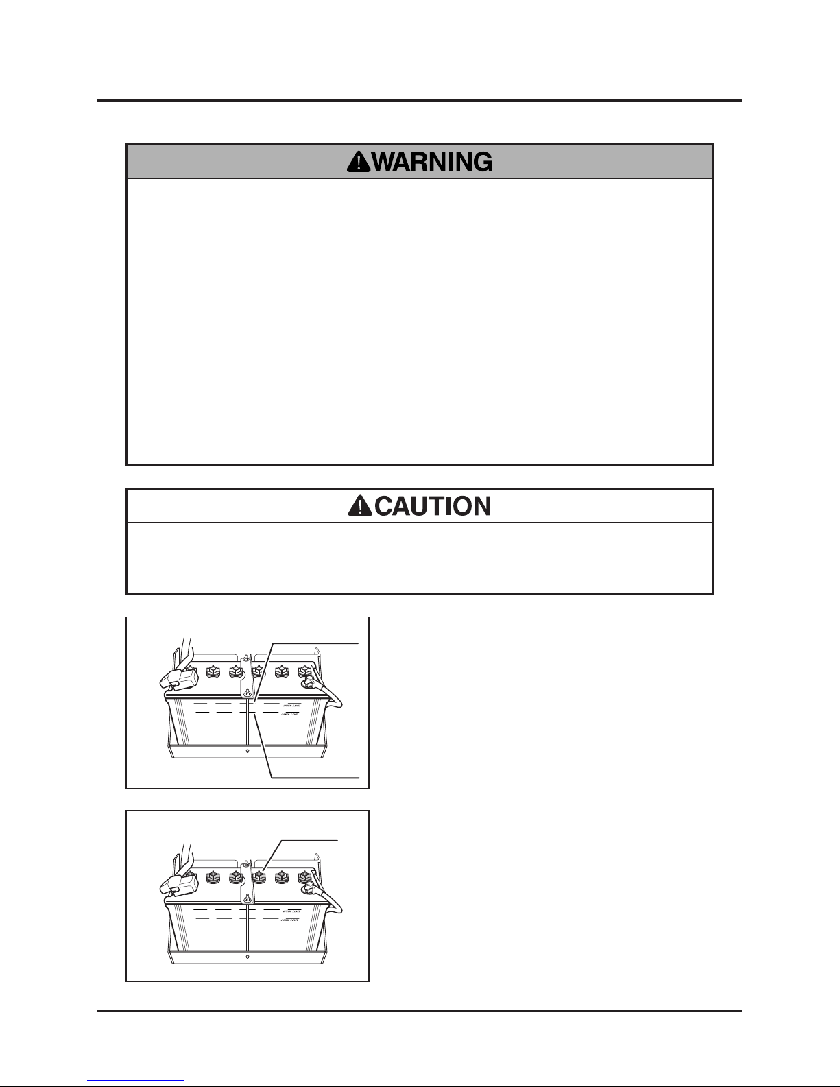
-63-
Maintenance 5
• Never ll battery uid beyond [Upper Level]. Battery uid may spill and cause
damage to machine or injury to person.
1. Park the machine on a level surface.
2. Visually inspect that battery uid level is
between "Upper Level" and "Lower Level"
lines.
3. If the uid level is below "Lower Level," ll.
Inspecting
UPPER LEVEL
LOWER LEVEL
5116M-0509-010E
Filling
1. Remove right side cover. (Page 44).
2. Remove ller caps.
3. Fill distilled water up to "Upper Limit."
4. Put ller plugs back in place.
Filler Cap
5116M-0509-020E
• Battery uid (diluted sulc acid) is corrosive and causes severe burns. Be
extremeley cautious when handling battery uid. If battery uid is spilt on
clothes, immediately rinse with plenty of water. If spilt on skin or in an eye,
immediately rinse with plenty of water and promptly consult a physician.
• Explosion hazard. Keep open ame or spark away from battery. Hydrogen gas
generated during charging is extremely explosive.
• Shock hazard: never touch battery terminal. Electrocution may result.
• Use wet cloth to clean battery. Dry cloth may generate static electricity, which
may cause explosion.
Page 73
Maintenance
-64-
5
Charging Battery
• Never charge battery when the uid level is below [Lower Level]. Charging
battery with insufcient uid may shorten battery life or cause an explosion.
• Battery uid (diluted sulc acid) is corrosive and causes severe burns. Be
extremeley cautious when handling battery uid. If battery uid is spilt on
clothes, immediately rinse with plenty of water. If spilt on skin or in an eye,
immediately rinse with plenty of water and promptly consult a physician.
• Explosion hazard. Keep open ame or spark away from battery. Hydrogen gas
generated during charging is extremely explosive.
• Shock hazard: never touch battery terminal. Electrocution may result.
• Always disconnect the negative (-) terminal rst, and connect the positive (+)
terminal rst. Disconnecting or connecting in the opposite order may cause a
short circuit.
• When installing the battery, make certain to connect the positive (+) and
negative (-) terminals to their respective original positions. Avoid contact
between terminals and other surrounding parts.
• Always remove battery from machine before charging. Failure to do so causes
damage to electrical components and wiring.
• When using battery charger, follow instructions in its operator's manual.
Page 74
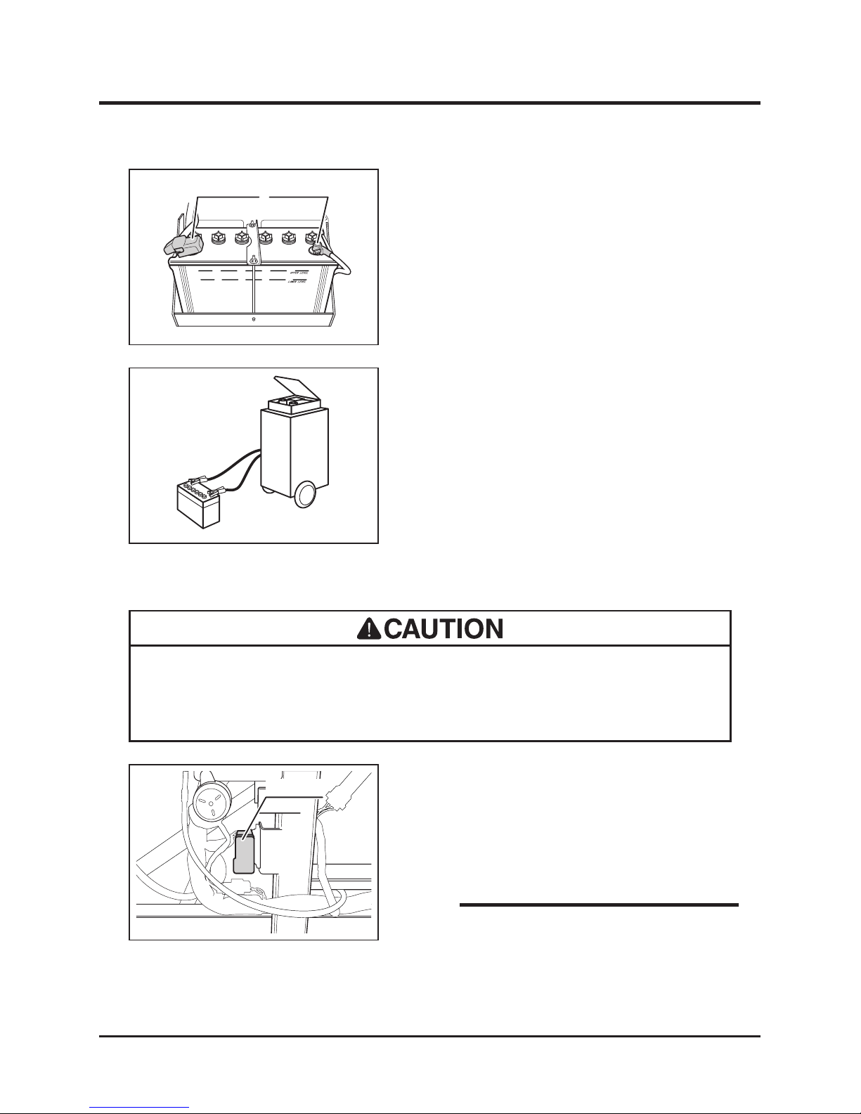
-65-
Maintenance 5
Fuses
1. Remove controls cover.
2. Open fuse box and inspect fuses.
3. If fuse is blown, replace it with a new one of
the correct amperage.
4. Close fuse box. Install controls cover.
• If a fuse blows, investigate the cause and repair it before replacing.
• Always replace a fuse with the one of the correct amperage.
1. Park machine on a level surface.
2. Remove right side cover.
3. Remove negative (-) cable from terminal.
4. Remove positive (+) cable from terminal.
5. Remove battery from machine.
+ Terminal - Terminal
5116M-0509-030E
Fuse Box
5116M-0509-050E
• Spare fuses (10A, 15A) are provided in fuse
box.
NOTE
5116M-0509-040E
6. Fol lo w i ns truct io ns in batt ery c ha rge r
operator's manual to charge battery.
7. When charge is complete, install battery to
machine.
8. Install right side cover.
Page 75
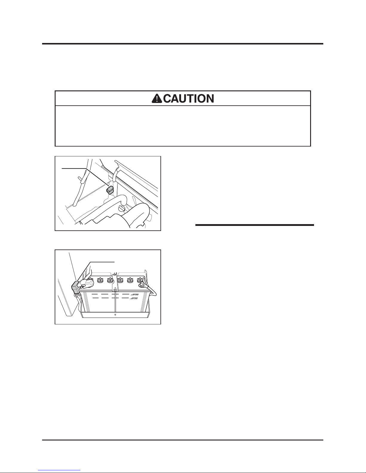
Maintenance
-66-
5
Slow-Blow Fuses
1. Open top cover and hold it securely in place
with prop.
2. Open fuse box and inspect fuses.
3. If fuse is blown, replace it with a new one of
the correct amperage.
4. Close top cover.
• If a slow-blow fuse blows, investigate the cause and repair it before replacing.
• Always replace a slow^blow fuse with the one of the correct amperage.
5116M-0509-060E
Fuse Box
• A spare fuse is provided in fuse box.
NOTE
Fuse Box
5116M-0509-070E
5. Remove right side cover.
6. Open fuse box and inspect fuses.
7. If fuse is blown, replace it with a new one of
the correct amperage.
8. Install right side cover.
Page 76
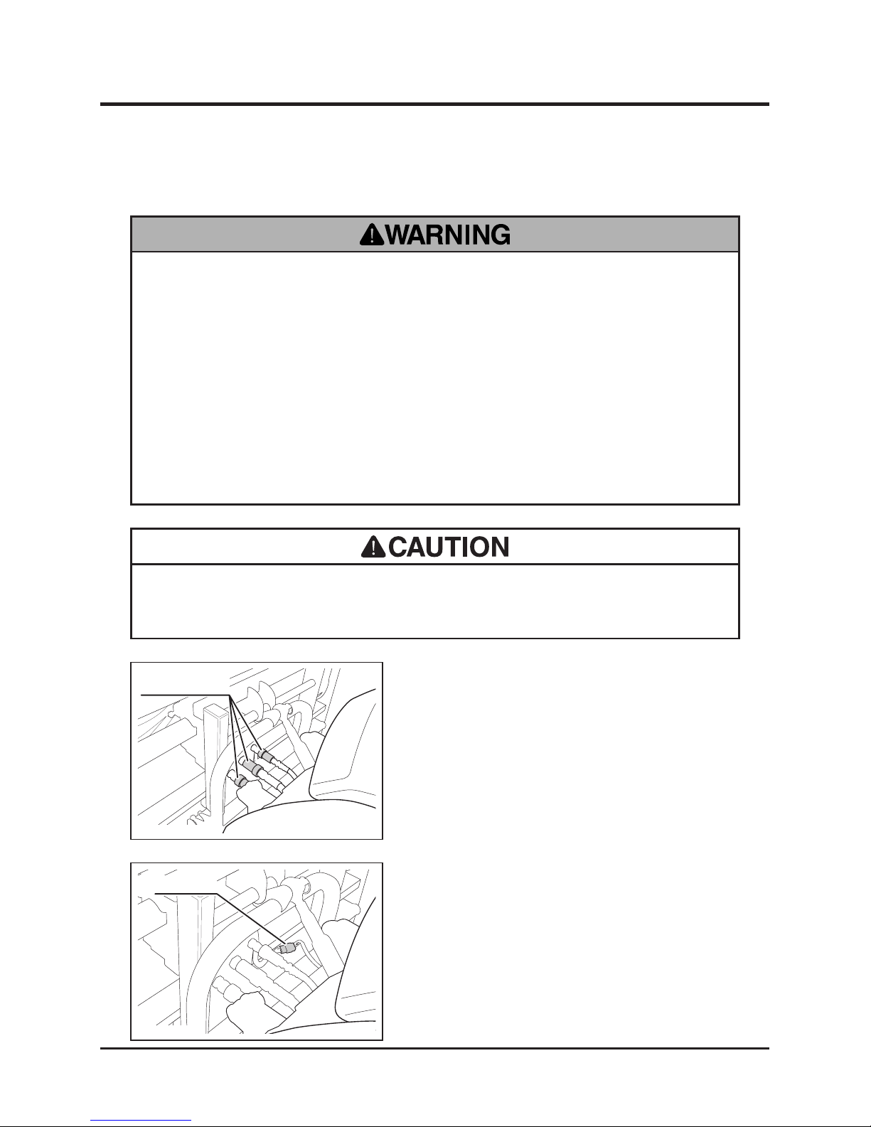
-67-
Maintenance 5
Attaching/Detaching Implement
Quick Couplers
5116M-0510-090E
1. Park machine on a level surface.
2. Lower implement until it rests on the ground.
3. Detach quick couplers on hydraulic hoses.
Connector
5116M-0510-120E
4. Detach connector on wiring harness.
• Never turn cutting on rotor switch when quick couplers are detached. Hydraulic
components or plumbing can be damaged.
Implement
• Park machine on a level surface when attaching or detaching implement.
• Do not go under implement.
• Always release residual pressure of hydraulic components when detaching
implement, or oil under high pressure may leak and penetrate through skin and
cause injury upon contact.
• Hydraulic uid is very hot right after use. Allow hydraulic uid to cool before
detaching implement, or severe burns may result.
Page 77
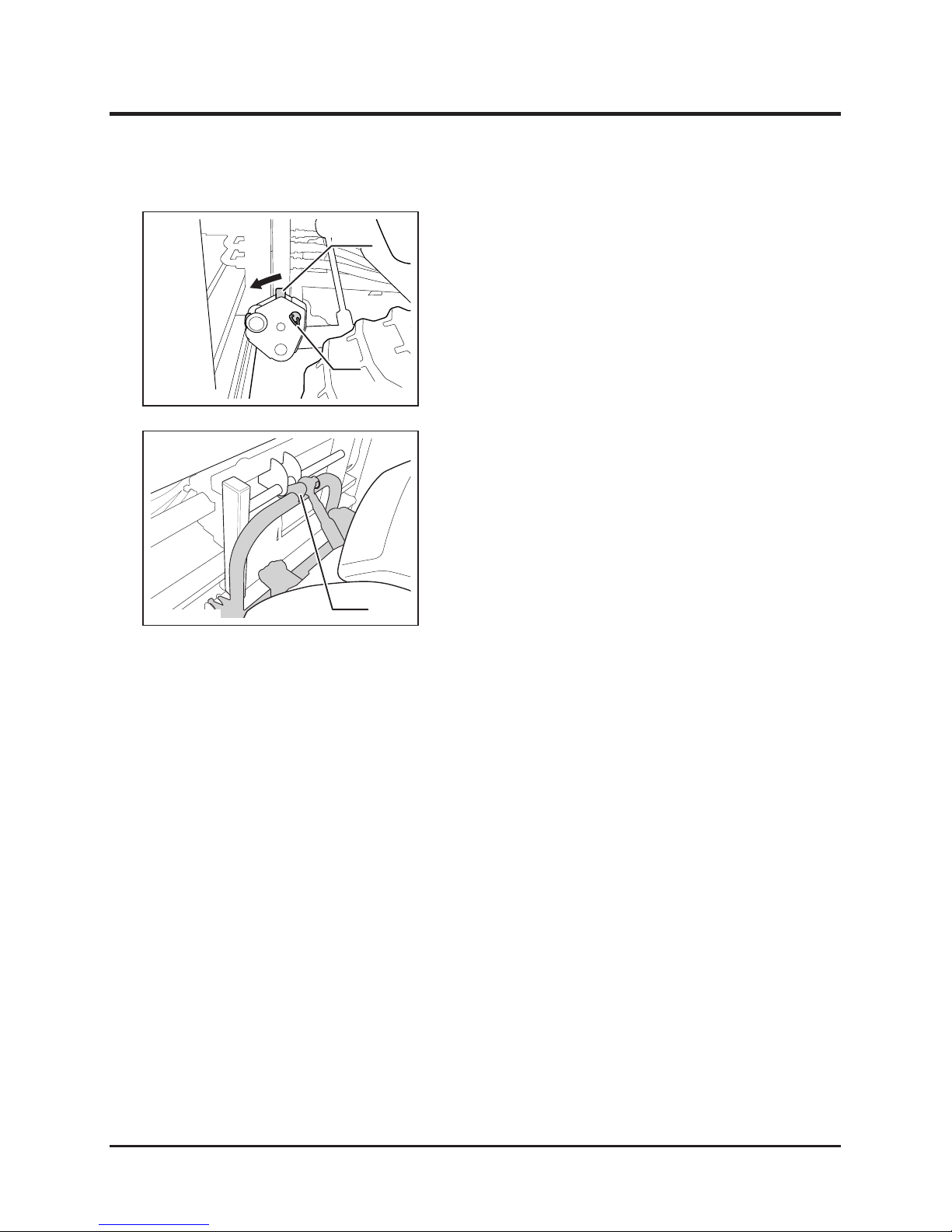
Maintenance
-68-
5
Lever
5116M-0510-100E
Pin
5. Remove link pins and pins. (2 places on both
sides.)
6. Fold down lever to unlock.
5116M-0510-110E
Joint
7. Lower link to unhook.
8. Drive backwards to remove implement.
Page 78
-69-
Maintenance 5
After Normal Use
1. Clean machine; wash off dirt, mud, and other foreign matter after use.
2. If machine is to be left outside, cover machine with protective, water-proof covering after
machine is cooled off.
• Do not wash engine, control panel, electrical parts, or tank caps with air
breather with running water; water may enter inside and cause rust or damage.
• Clean machine after use; leaving dirt or foreign objects may cause damage.
• Do not attempt to move machine when it becomes inoperable due to freezing.
1. Clean machine; wash off dirt, mud, and other foreign matter after use.
2. Park machine on a paved or rm, dry surface.
3. If machine is to be left outside, cover machine with protective, water-proof covering after
it is cooled off.
After Use Care
After Cold Weather Use
Page 79
Maintenance
-70-
5
Storage
1. Park machine.
2. Clean dirt off of machine.
3. Check machine according to Maintenance Schedule chart (Page 34) and service as
necessary.
4. Clean steel parts of machine with oil-soaked rag. Grease greasing points.
5. Change engine oil.
6. Completely drain coolant from engine cooling system.
7. Clean air cleaner.
8. Drain fuel from fuel tank.
9. Remove battery from machine. Service battery.
10. Cover machine with protective, water-proof covering after machine is cooled off.
• Do not wash engine or control panel with running water; water may enter inside
and cause rust or damage.
• Clean machine before storage; leaving dirt or foreign objects may cause rust or
damage.
• Do not store machine in a humid, dusty, or hot place.
• Fire hazard; do not store machine where there is a possiblity of ignition.
• Battery dischages even when it is not in use. A battery may hold charge for a few
months, but it is a good practice to charge battery before it goes at; it will extend
the battery life.
• Refer to the Operation Manual for the engine, for detailed instructions on preparing
engine for storage.
NOTE
Page 80
-71-
Troubleshooting
6
Troubleshooting
• If any malfunction or abnormal condition is found, immediately stop using the
machine and take an appropriate measure according to the Troubleshooting chart
below. If the malfunction or abnormal condition is not listed in the chart, or the
suggested measure does not solve the problem, consult with your CANYCOM
representative.
• Some corrective measu r e s l i s t ed below require special k n o w l e d g e and/or
equipment. Please contact your CANYCOM representative in such a case.
Area Malfunction Possible Cause Corrective Measure Ref.
Engine
Engine does not start,
or is difcult to start
Out of fuel. →Fill fuel. Page 16
Air in fuel line. →Bleed fuel line. Page 52
Water in fuel system →Drain water. Page 52
Insufcient battery
capacity
→Add battery uid.
→Charge battery.
→Replace battery.
Page 62
Insufcient or wrong
oil.
→Fill or change oil. Page 45
Other (other than the
above).
→Follow the
instructions in
"Starting" to restart.
If problem persists,
please contact
your CANYCOM
representative.
Page 18
Engine stalls.
Out of fuel. →Fill fuel. Page 16
Air in fuel line. →Bleed fuel line. Page 52
Cold engine. →Warm up engine.
Other (other than the
above).
→Please contact
your CANYCOM
representative.
Engine stops abruptly.
Out of fuel →Fill fuel. Page 16
Other (other than the
above).
→Please contact
your CANYCOM
representative.
Idling is not stable.
Insufcient intake air
(clogged air cleaner).
→Clean or replace the
air cleaner.
Page 50
Other (other than the
above).
→Please contact
your CANYCOM
representative.
Page 81
Troubleshooting
-72-
6
Area Malfunction Possible Cause Corrective Measure Ref.
Engine
Engine does not stop
Electrical malfunction →Please contact
your CANYCOM
representative.
Other (other than the
above).
→Please contact
your CANYCOM
representative.
Poor power or
acceleration
Bad fuel →Change fuel.
Wrong oil (wrong
viscosity)
→Change for correct
oil.
Page 45
Insufcient intake air
(clogged air cleaner).
→Clean or replace the
air cleaner.
Page 50
Other (other than the
above).
→Please contact
your CANYCOM
representative.
Irregular noise or
vibration from or
around the engine
Loose engine mount
bolt(s).
→Tighten.
Other (other than the
above).
→Please contact
your CANYCOM
representative.
Excessive oil
consumption
→Please contact
your CANYCOM
representative.
Engine overheats
Radiator or cooling fan
is clogged or blocked.
→Clean.
Hydraulic cooling fan
is in a wrong mode.
→Follow the
instructions in
"Hydraulic Cooling
Fan" to select an
appropriate mode for
the condition.
Page 32
Hydraulic cooling fan
is faulty.
→Please contact
your CANYCOM
representative.
Insufcient amount of
engine oil.
→Fill oil. Page 45
Insufcient amount of
coolant.
→Fill coolant. Page 47
Other (other than the
above).
→Please contact
your CANYCOM
representative.
Page 82

-73-
Troubleshooting
6
Area Malfunction Possible Cause Corrective Measure Ref.
Engine
Excessive fuel
consumption
Clogged air cleaner. →Clean or replace the
air cleaner.
Page 50
Other (other than the
above).
→Please contact
your CANYCOM
representative.
Black smoke comes
out of exhaust
Clogged air cleaner. →Clean or replace the
air cleaner.
Page 50
Other (other than the
above).
→Please contact
your CANYCOM
representative.
White or blue smoke
comes out of exhaust
Engine oil level is too
high.
→Adjust oil level. Page 45
Wrong oil (wrong
viscosity)
→Change for correct
oil.
Page 45
Other (other than the
above).
→Please contact
your CANYCOM
representative.
Accelerator lever is
catching
Faulty wire, rod or
linkage.
→Please contact
your CANYCOM
representative.
Other (other than the
above).
→Please contact
your CANYCOM
representative.
Drive
Train
Machine does not
move when control
stick is operated.
Faulty hydraulic
system.
→Refer to "Hydraulic
Systems."
Page 54
Other (other than the
above).
→Follow the
instructions in
"Driving" to drive
the machine. If
problem persists,
please contact
your CANYCOM
representative.
Page 22
Machine does not turn
properly.
Faulty hydraulic
system.
→Refer to "Hydraulic
Systems."
Page 54
Other (other than the
above).
→Please contact
your CANYCOM
representative.
Page 83

Troubleshooting
-74-
6
Area Malfunction Possible Cause Corrective Measure Ref.
Drive
Train
Machine does not run
straight
Tracks are not properly
adjusted.
→Adjust. Page 58
Control stick is not
properly adjusted.
→Adjust. Page 61
Other (other than the
above).
→Please contact
your CANYCOM
representative.
Machine vibrates
abnormally, or is not
stable.
Track is derailed. →Reinstall and adjust
track.
Page 58
Roller, sprocket, or
idler is loose.
→Tighten the loose
fastener.
Other (other than the
above).
→Please contact
your CANYCOM
representative.
Brake
Parking brake does not
work well.
Faulty hydraulic
system.
→Refer to "Hydraulic
Systems."
Page 54
Other (other than the
above).
→Please contact
your CANYCOM
representative.
Hydraulic
System
Hydraulic equipment
(hydraulic motor,
cylinder) does not
work properly or does
not work at all.
Insufcient hydraulic
uid.
→Fill or change. Page 54
Clogged hydraulic oil
lter
→Change. Page 57
Other (other than the
above).
→Please contact
your CANYCOM
representative.
Cylinder contracts.
Foreign object caught
in pilot check valve.
→Please contact
your CANYCOM
representative.
Faulty electromagnetic
valve.
→Please contact
your CANYCOM
representative.
Other (other than the
above).
→Please contact
your CANYCOM
representative.
Page 84
-75-
Troubleshooting
6
Area Malfunction Possible Cause Corrective Measure Ref.
Implement
Drive
Implement does not
run.
Faulty hydraulic
system.
→Refer to "Hydraulic
Systems."
Page 54
Other (other than the
above).
→Follow the
instructions in
"Working" to operate
the machine. If
problem persists,
please contact
your CANYCOM
representative.
Page 26
Implement vibrates
excessively when it is
run.
Foreign object is
tangled.
→Untangle.
Other (other than the
above).
→Please contact
your CANYCOM
representative.
Safety
Devices
Warning lamp does not
light.
Blown fuse. →Replace.
Blown bulb. →Replace.
Other (other than the
above).
→Please contact
your CANYCOM
representative.
Oil lamp stays on after
engine starts.
Insufcient engine oil. →Fill. Page 45
Other (other than the
above).
→Please contact
your CANYCOM
representative.
Coolant Temperature
lamp stays on after
engine starts.
Engine overheats. →Refer to "Engine." Page 45
Other (other than the
above).
→Please contact
your CANYCOM
representative.
Charge lamp stays on
after engine starts.
Blown fuse. →Replace.
Other (other than the
above).
→Please contact
your CANYCOM
representative.
Horn does not work.
Blown fuse. →Replace.
Other (other than the
above).
→Please contact
your CANYCOM
representative.
Page 85

Transporting
-76-
7
• Park transporter (truck) on a level ground. Always use chocks to secure wheels.
• Do not allow bystandars to come close to machine or transporter when loading
or unloading machine.
• Use only the loading ramps with sufcient strength (to withstand the combined
weight of machine and operator), width (more than 1.2 times the width of track),
and length (more than 4 times the height of loading deck of transporter), and
have anti-slip ramp surfaces.
• Secure hooks of loading ramps rmly and ush with loading deck.
• Move slowly forward when loading onto, and move slowly backward when
unloading off of transpor ter. Pa y spec ial care when going over the joint
between loading deck and ramps; machine may tip.
• Do not turn on loading ramps. Machine may fall.
• Tie down machine securely. Make sure machine does not move around on
loading deck.
Hauling
Loading and Unloading
Page 86
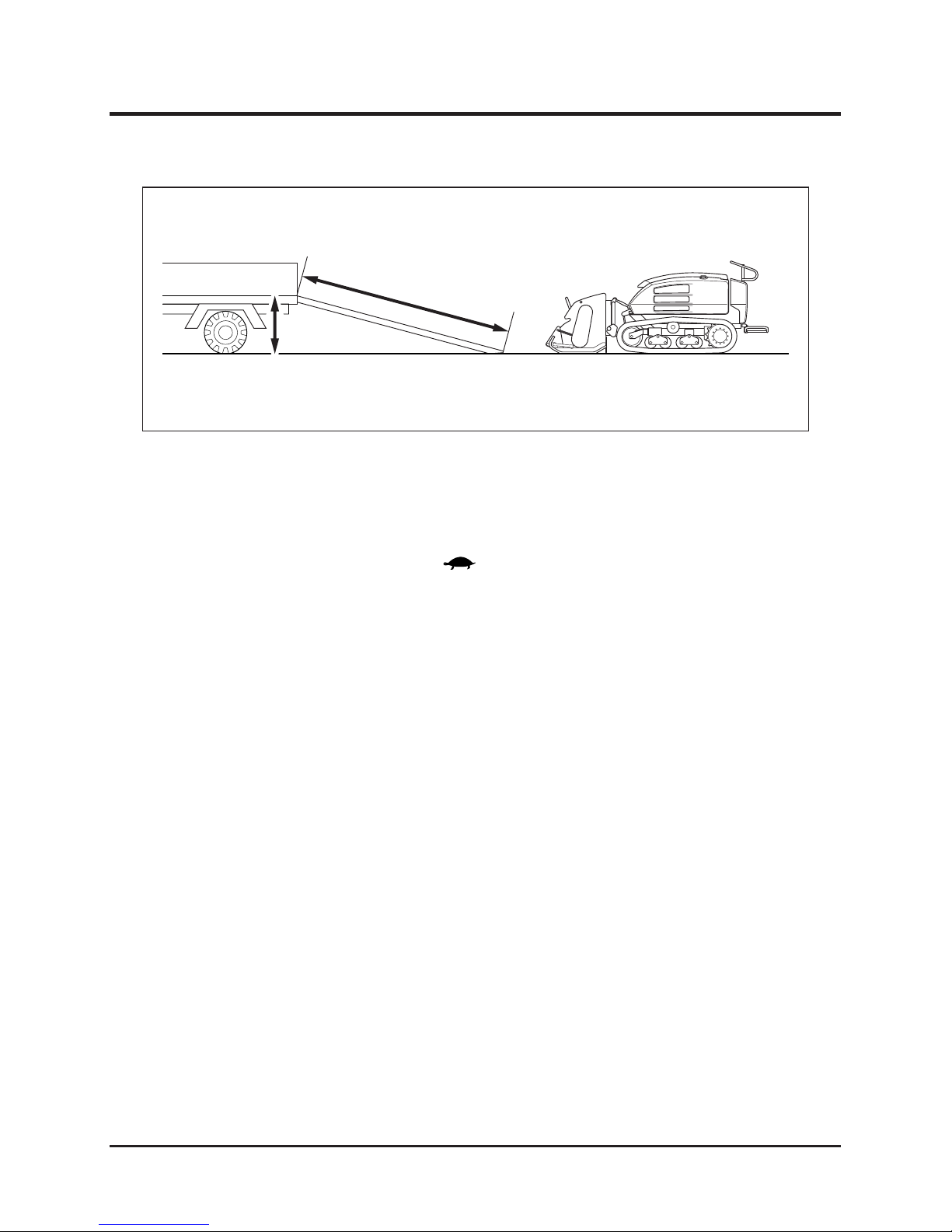
-77-
Transporting
7
5116M-0701-010E
More than 4 times
the height
Height
Note: Typical configuration with mower implement (CG431 Mower) shown.
Loading to Transporter
1. Park transporter. Secure wheels with chocks.
2. Place loading ramps. Secure hooks of ramps rmly and ush with loading deck.
3. Lift up implement.
4. Set auxiliary transmission switch to [ (slow)]. Raise cutting rotor so that it does not
hit ramp or loading deck of transporter. Drive machine slowly forward onto loading deck.
5. Park machine according to the instructions in "Stopping" (Page 24). Tie machine down
with rope or tie-down belts and secure it onto loading deck of transporter securely.
Page 87
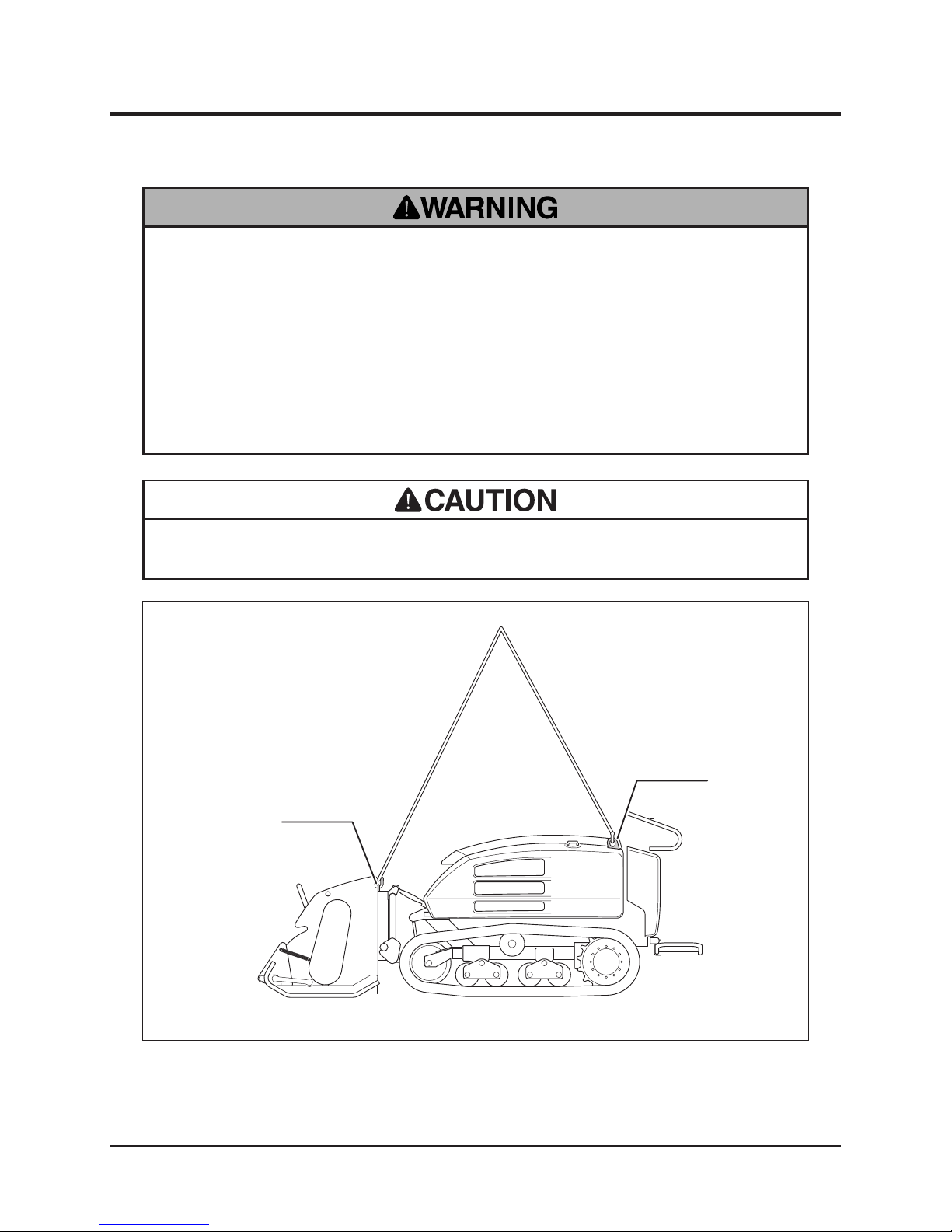
Transporting
-78-
7
• Do not use wire rope when hoisting. It will damage tracks.
Hoisting
1. Attach hoisting slings to hitch points of machine. Hoist the center of slings.
5116M-0702-010E
Hitch Point
Hitch Point
• Hoisting may require appropriate training or licence. Consult with your local
authority.
• Use hoisting sling of sufcient strength. Always use slings of the same length
when more than one is used.
• Pay at tention to the balanc e and the location of the cen ter of gravity of
machine.
Page 88
Model
Engine
LwA
Type Type Speed rpm
CG431 Kubota V2203 2,800 rpm 98 dB (A)
NOISE LEVEL evaluated based on factory standard.
NOISE LEVEL
Model
Engine
Rated revolution
Steering lever Seat
CG431 2,800 rpm 3.0 m/s
2
3.0 m/s
2
VIBRATION evaluated based on factory standard.
VIBRATION
 Loading...