

Page 1

OPERATOR'S MANUAL
July2003,35587002000
Read this manual completely before operating or maintaining this machine.
Failure to follow safety precautions could result in serious injury or death.
Keep this manual for future reference for you and for all those who operate and
maintain this machine.
WARNING
CHIKUSUI CANYCOM, INC.
90-1 Fukumasu, Yoshiimachi,
Ukihagun,Fukuoka,Japan839-1396
Te l.(09437)5-2195 Fax.(09437)5-4396
Off-Road Rubber Track Carrier
BP416/BP416D
BP415/BP415D
Page 2
The machine can be very dangerous if the safety precautions in this
manual and on the labels attached to this machine are not followed.
Always follow the instructions and safety precautions, or serious injury
or death could result.
This machine should only be used for its intended purpose: hauling and
dumping.
Any other use could be dangerous.
Also driving this machine on a public road or a road regarded as a public road may be illegal.
WARNING
Do not modify this machine. Also do not remove the safety cover of the
body before running. A serious accident could result.
WARNING
Notice to Users and Maintenance Personnel
Thank you for purchasing this machine.
Always be sure to read and understand this manual thoroughly before using
your machine. This will enable you to use it correctly.
Warning Words Used in this Manual
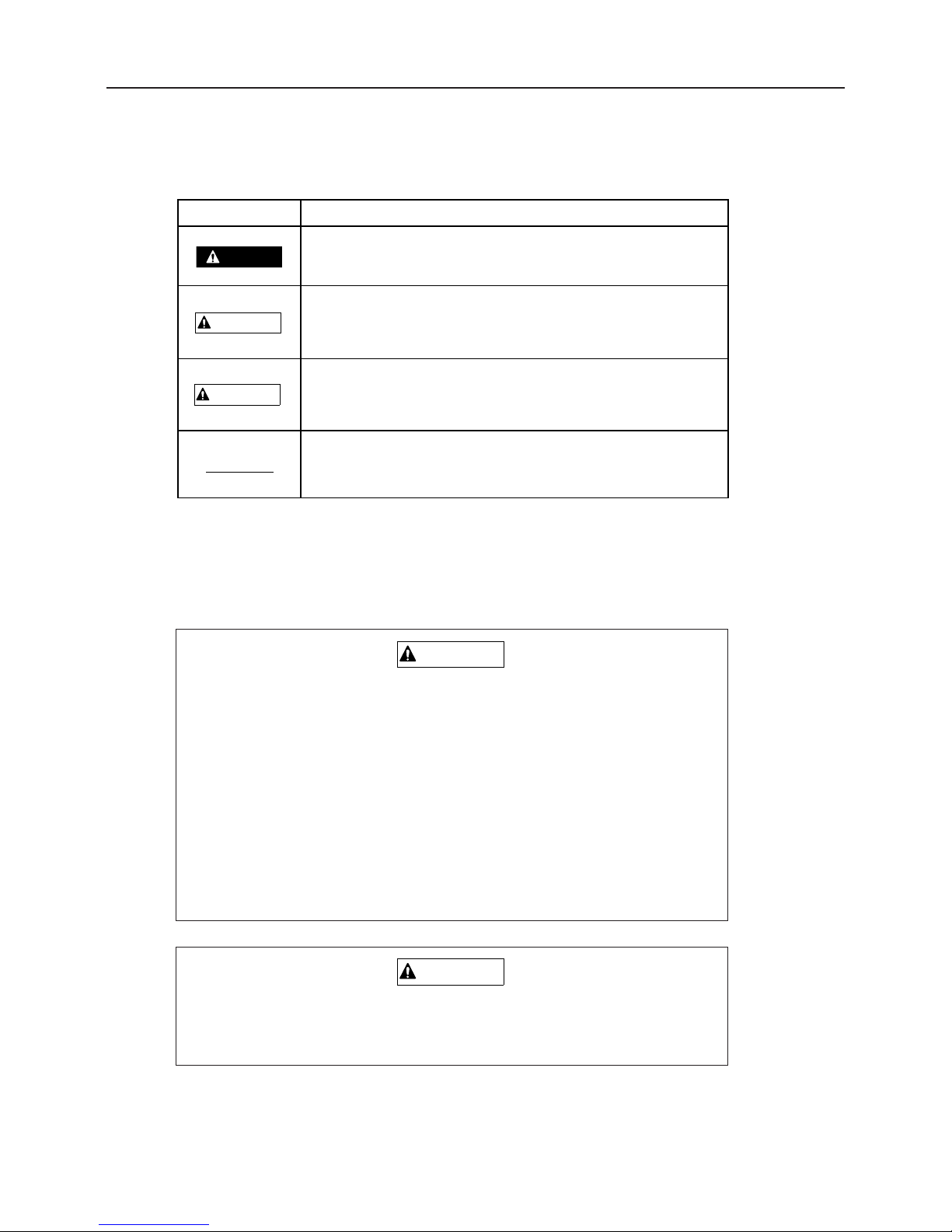
To indicate the level of danger (or the degree of the failure), the following four signal words
are used to identify the safety messages in this manual. Their meanings are as follows.
Signal word Meaning
Indicates an imminently hazardous situation which, if not avoided
by following these instructions and precautions, will result in death
or serious injury.
Indicates a potentially hazardous situation which, if not avoided by
following these instructions and precautions,
could result in death or serious injury.
This word is used for precautions that are recommended or to
emphasize the importance of information.
Indicates a potentially hazardous situation which, if not avoided by
following these instructions and precautions, may result in minor or
moderate injury.
WARNING
CAUTION
DANGER
NOTICE
Page 3

Contents
1. Introduction 1
1.1 Purpose of this Manual ............................................. 1
1.2 Structure of this Manual ............................................ 1
1.3 Warning Labels Attached to this Machine ......................... 2
2. Warranty and After-sales Service 3
3. Rules for Safe Operation and Maintenance 4
4. Component Names and Functions 9
5. Product Specifications 10
5.1 Specifications of this Product ..................................... 10
5.2 Details of Tool Bag ................................................. 11
6. Operation 12
6.1 Preparation Before Operation .................................... 12
6.1.1 Checking Fuel and Adding Fuel ...................................... 12
6.1.2 Checking Engine Oil Level and Adding Oil ............................. 12
6.2 Method of Starting ................................................. 13
6.3 Method of Operating .............................................. 15
6.4 Stopping ............................................................ 17
6.5 Operating Dump ..................................................... 18
6.5.1 Operating Dump (Manual Dump) ..................................... 18
6.5.2 Operating Dump (Hydraulic Dump) ................................... 19
Page 4

7. Maintenance 20
7.1 Periodic Inspection Table ......................................... 20
7.2 Fuel, Lubricant, and Coolant Chart .............................. 24
7.3 Replacement Parts Chart ......................................... 24
7.4 Adding Oil .......................................................... 25
7.4.1 Engine Oil ......................................................... 25
7.4.2 Transmission Fluid ................................................. 26
7.4.3 Power Package Fluid (Fluid for Hydraulic Dump) ....................... 27
7.5 Lubricating ......................................................... 28
7.6 Cleaning ........................................................... 29
7.6.1 Air Cleaner Element ................................................ 29
7.6.2 Ignition Plug ....................................................... 29
7.6.3 Fuel Cock (Fuel Filter) .............................................. 30
7.7 Adjustments ........................................................ 31
7.7.1 V-belt ............................................................. 31
7.7.2 Clutch ............................................................ 31
7.7.3 Brake ............................................................. 32
7.7.4 Side Clutch ........................................................ 33
7.7.5 Track Tension ...................................................... 34
7.7.6 Belt Stopper ....................................................... 35
7.8 Maintenance After Use ............................................ 35
8. Storage (Long-term Storage) 36
8.1 Machine ...............................................................36
8.2 Engine .............................................................. 37
8.2.1 Fuel Cock ......................................................... 37
8.2.2 Cleaning Air Cleaner Element ....................................... 37
8.2.3 Replacing Engine Oil ............................................... 37
Page 5

9. Troubleshooting 38
10. Transporting Machine 42
< Guarantee Certificate >
Attached to end of this manual.
* Receive the guarantee certificate together with a receipt after you have
received instructions for handing this machine.
< Appendix >
"Instruction manual for engine"
* Be sure to read it together with this manual.
Page 6

Introduction
– 1–
1. Introduction
1.1 Purpose of this Manual
The purpose of this manual is to provide detailed information needed for the safe and
effective use of this machine to those who operate or maintain the machine.
1.2 Structure of this Manual
This manual contains the following chapters.
1. Introduction
This section explains the purpose and structure of the manual and the warnings used in the
manual. It also describes the warning labels attached to the machine.
2. Warranty and After-service
This section covers items related to the warranty and after- service for this machine.
3. Points to Remember for Safe Operation
This section covers general safety items that must be followed when operating or using
this machine.
4. Explanation of Components
This section explains the names and functions of the parts of the machine.
5. Product Specification
This section gives the specifications of this machine. It also gives details about the tool bag.
6. Operation
This section explains the preparations before operating the machine, the order of operation,
and the method of operation.
7. Maintenance
This section gives information about periodic inspection, use of coolant, lubricants. and
grease, and cleaning, replacing, adjusting, and maintenance of the machine after use.
8. Storage (Long-term Storage)
This section gives information about storage (long-term storage) of the machine.
9. Troubleshooting
This section describes the action to take if any problem occurs.
10. Transporting Machine
This section explains the methods and precautions when transporting the machine.
Page 7

Introduction
– 2–
3558M-0103-030
1.3 Warning Words Used in this Manual
To indicate the level of danger (or the degree of the failure), the following four signal words are
used to identify the safety messages in this manual. Their meanings are as follows.
Replace these labels immediately if they have been removed, fallen off, or have become illegible.
Use the part numbers on the label to order replacement labels from dealer.
NOTICE
Page 8

– 3–
Warranty and After-sales Service
2. Warranty and After-sales Service
Warranty
Chikusui Canycom, Inc. provides a warranty to you through their local dealers. Consult your local dealer
regarding the details of warranty.
After-sales Service
Please contact your Canycom distributor from whom you purchased your machine or our Service
Center regarding service orders or any questions or problems that may arise when using the Off-road
Rubber Track Carrier.
Please inform us of the product model that you own or use and the product serial number specified on
the model label (See illustration below for location of the label).
Please refer to the "Specifications" in Chapter 5 for the name of the manufacturer of the engine
installed in your machine, as well as the engine model.
Location of
model label
3559M-0103-020
BP415
Product model
Serial number
< Location of Model Label >
< Model Label >
Availability of Repair Parts
Repair parts for this product will be available for seven years after manufacturing of this machine is discontinued.
Page 9

Protective Clothing
Wear clothes suitable for the operation of heavy equipment. Protective footwear, long pants, and longsleeved shirts are recommended.
Pre-work Check
Perform the daily pre-operation check before starting
the machine.
Repair or replace damaged parts before starting the
machine.
Fuel Handling
Do not handle fuel or grease, service the engine, or
recharge the battery while smoking or when near an
open flame.
– 4–
Rules for Safe Operation and Maintenance
3. Rules for Safe Operation and Maintenance
This chapter describes general safety precautions that must be followed during operation and maintenance.
Be sure that all users and maintenance personnel are familiar with these rules and that they follow them.
Safety Precautions before Operation
B1-001
A1-001
B1-002
B1-003
Do Not Carry Passengers on this Machine
Driving the Off-Road Rubber Track Carrier with a passenger or passengers can change the center of gravity
and make the machine difficult to handle.
This product was designed to be operated carrying only
one person-the driver. Driving with passengers are
extremely dangerous.
Page 10

– 5–
Rules for Safe Operation and Maintenance
B1-004
Do Not Start, Accelerate, Turn, or Brake Quickly
B2-003
B2-002
B2-001
Do Not Drive Recklessly
Do not operate this machine when under the influence
of alcohol or when fatigued.
No one under age18 should operate this vehicle.
Maintain Safe Speed
When driving the machine, always drive at a safe speed
suitable for the load in the dump body and the conditions of the road surface and grade of the road.
Work with an Observer in Dangerous
Situations
When operating the machine where there is poor visibility, rugged terrain, hills, or limited maneuvering room,
use an observer to help direct the machine 's movement. The observer should be able to see the machine
and its immediate surroundings, and should use prearranged signals to direct the driver's actions.
No Quick Starting Acceleration, Turning or
Braking
Drive safely and avoid sudden changes of speed or
direction. Make sure the area around the machine is
safe for driving. Do not make sudden maneuvers or turn
sharply when driving on soft or wet ground; this can
cause the machine to lose traction or turn over.
Page 11

– 6–
Rules for Safe Operation and Maintenance
Engine Brake on Downhill
Before a downhill, temporarily stop and move the
gearshift lever to the low speed position. Ensure to
apply the engine brake for deceleration. If the vehicle is
stopped without decelerating sufficiently, the vehicle
body may be lifted.
Precautions When Carrying a Load
150
kg
15°〜20°
B2-004
B2-005
B3-001
B3-002
Observe Weight Limit of a Bridge or
Overpass
Before crossing a bridge or overpass, be sure that the
total combined weight of the machine and the load does
not exceed the stated weight limit for the bridge or overpass.
Then cross the bridge or overpass carefully at a constant speed.
Observe the Machine's Load Limit on a
Slope
Driving on slopes can be dangerous. This is particularly
true when you are driving with a load. Do not exceed
150kg, when traveling on slopes of 15゜to 20 ゜.
If you must drive on slopes of more than 20 ゜, the
machine must not carry a load.
Do Not Drive Across a Slope to Drive on
the Slope
Always travel straight up and down a slope. Never travel
across a slope or along a contour line. Driving across a
steep slope or along a contour line is dangerous and
may cause the machine to tip over causing serious injury
or death. Do not operate the side clutch lever when the
vehicle is positioned on sharply sloping ground. If use of
the lever cannot be avoid, do so quickly and carefully,
taking care not to cause a reverse turn.
Page 12

– 7–
Rules for Safe Operation and Maintenance
Precautions when parking
B3-003
B3-004
B4-001
B4-002
Never Overload
Do not load the machine in excess of the working
capacity of 150kg.
Load Vehicle Properly
Load cargo on the load deck so it is evenly distributed
and strap the cargo to the load deck to avoid cargo
weight imbalance and shifting.
Do not load cargo on the load deck to a height that
obstructs the operator's field of view.
Do Not Park on Unstable or Inclined
Surfaces
Check for Safety at Parking and Enforcement of Chock
on Slope When parking, move the running clutch lever
to the "STOP" position (Brake ON), and stop the
engine. Avoid parking on a slope. If the vehicle must
be parked unavoidably, ensure to chock up the wheels.
Do Not Park on Unstable or Inclined
Surfaces
Park the machine on a stable, level, flat surface.
If parking on a slope is unavoidable, apply the parking
brake and block the rubber tracks at the lower end of
the machine.
Observe all precautions for driving and operating the
machine and transporting a load on a slope.
Page 13

– 8–
Rules for Safe Operation and Maintenance
Precautions When Performing Maintenance
B5-001
B5-002
Ventilate Properly when Operating Indoors
When operating engine indoors, always ensure that
there is adequate ventilation to prevent poisoning by
exhaust gas.
Never carry out maintenance with engine
running
Do not carry out maintenance with the engine running.
Always stop the engine before starting maintenance.
Page 14

4.
Component Names and Locations
Locations
Component Names
① Throttle lever .......................This is used to increase or decrease the speed of the engine.
② Side clutch lever ...................This is used when changing the running direction. The vehicle
is turned to the side on which the clutch lever is grasped by
hand. When the right and left levers are grasped at the same
time, the vehicle is stopped immediately.
③ Clutch lever ........................This is used to interrupt the transmission of power from the
engine to the transmission. When the lever is lowered, the
operation mode becomes "RUN" (travel). When the lever is
raised, the operation mode becomes "STOP" (stop). The lever
is interlocked with the brake. When the lever is at the "STOP"
position, the brake is applied.
④ Gear shift lever .....................This is used to select the running speed. Before operating this
lever, move the clutch lever to the " STOP" position (upper
side) to stop the vehicle.
⑤ Hydrauliclever .....................This is used to raise or lower the deck.
Component Names and Locations
– 9–
3558M-0400-010E
Page 15

Product Specifications
– 10 –
5. Product Specifications
5.1 Specifications of this Product
Manual dump Hydraulic dump
Flat-bed type Sliding panel Bucket type Flat-bed type Bucket type
Overall length 1790 1650(1810) 1750 1775 1750
Overall width 830 620(975) 620 830 620
Overall height 980
Length 1050 950(1110) 1080 1050 1080
Width 745 520(900) 550 745 550
Height 200 420 260 200 260
Grand contact length 700
Shoe width 180
Tread 440
Engine Continuous rated output 2.1kW/1800min
-1
Machine weight (kg) 160 150 155 180 165
Maximum payload capacity kN(kg) BP415: 2.45(250),BP416: 2.94(300)
Minimum turning radius (mm) 1200
Minimum ground clearance (mm) 90
Height of bed floor (mm) 370 380 370
Without load 25°
With Max. load 15°
Bucket capacity (m3)- -0.066 - 0.066
Left 41°
Right 39°
Left 25°
Right 25°
F1 2.0
F2 4.5
R1 1.5
R2 3.5
Clutch Belt tension system
Brake lnner expansion system
Dump angle5 0° 55° 63° 57° 63°
BP415 / BP416
Model
Measurement
(mm)
Bedinnersize
(mm)
Crawler
(mm)
Gradeability
Stability
Withoutload
WithMax.load
Speed
Reverse (kw/h)
Forward(kw/h)
* These specifications are subject to change without notice, for product improvement.
Read and understand the specifications of this machine to use
and maintain the machine properly.
NOTICE
Page 16

Product Specifications
– 11 –
No. Part Name Q'ty Remarks
1
Operation and Maintenance Manual (this manual)
1
2Instruction manual for engine 1
3 Engine tools 1
For engine maintenance and repair
5.2 Details of Tool Bag
Page 17
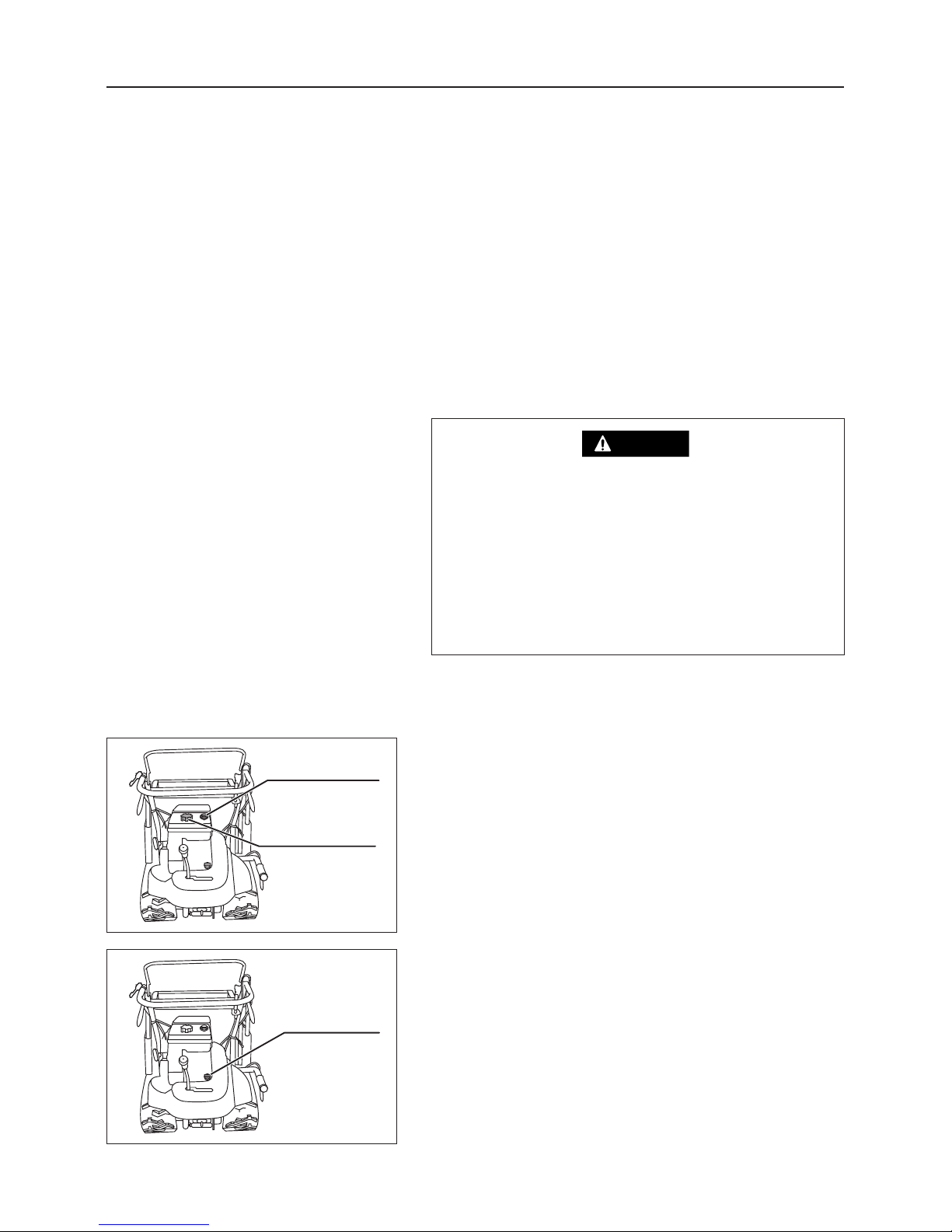
6.1 Preparation Before Operation
6.1.1 Adding Fuel
1. Visually check the oil level gauge. If fuel is low, open
the fuel tank cap, and add fuel.
Fuel to use: Lead free gasoline for cars
Fuel tank capacity: 2.2 liters
6.1.2 Checking Engine Oil Level and Adding Oil
1. Remove the engine oil filler plug (this plug has a
dipstick).
Oil level gauge
Fuel tank cap
Oil filler plug
– 12 –
Operation
3558M-0601-010
3558M-0601-020
6. Operation
• Before reading this section, be sure to read Section 3 "Rules for Safe Operation and
Maintenance"(see pages 4-8).
• When operating the machine, always follow the instructions in this section. Do not operate the
machine unless you are familiar with the operation of all controls and safety devices.
• When adding fuel, keep open flames (lighted
cigarettes, etc.) away from fuel and engine.
Flames will cause the fuel to ignite.
• Always stop the engine before adding fuel.
• Do not overfill so that fuel spills out of filler cap.
Wipe up any spilt before starting engine.
DANGER
Page 18
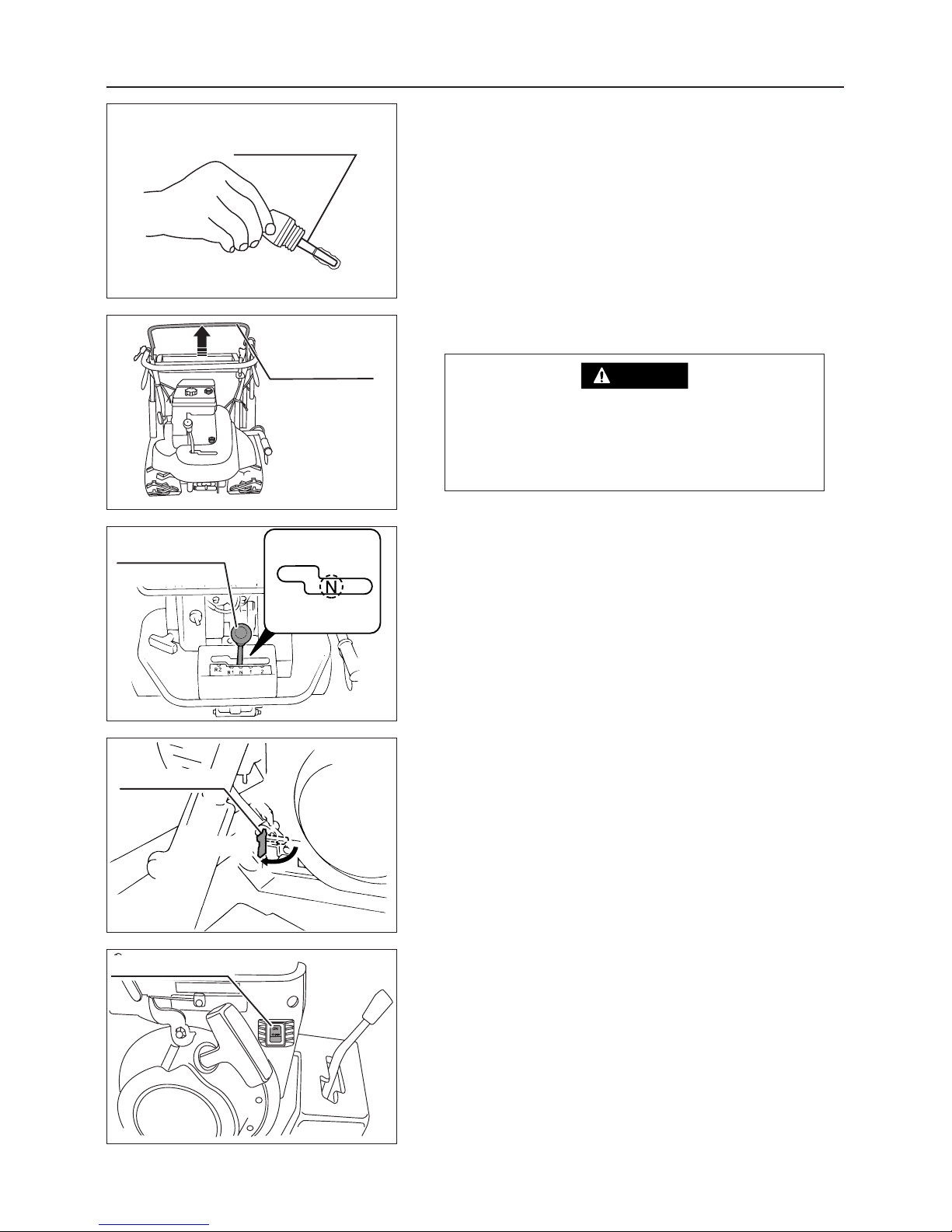
Gear shift lever
Engine switch
Fuel cock
OPEN
Drive clutch lever
Dipstick
– 13 –
Operation
2. Visually check the engine oil level. If it is not within
the specified levels, add engine oil.
Oil to use: See page 23
Engine oil quantity : Between "F" and "L" on the
dipstick.
3560M-0602-040
3560M-0601-030
3558M-0602-010
3560M-0602-020
3560M-0602-030
6.2. Method of Starting
Before starting the engine, remove any
flammable material from around the engine.
Area around the engine should be well ventilated.
DANGER
1. Move the drive clutch lever to the "STOP" position.
2. Move the gear shift lever to the "NEUTRAL (N)" position.
3. Turn the fuel cock to "OPEN".
4. Move the engine switch to the "ON" position.
Page 19
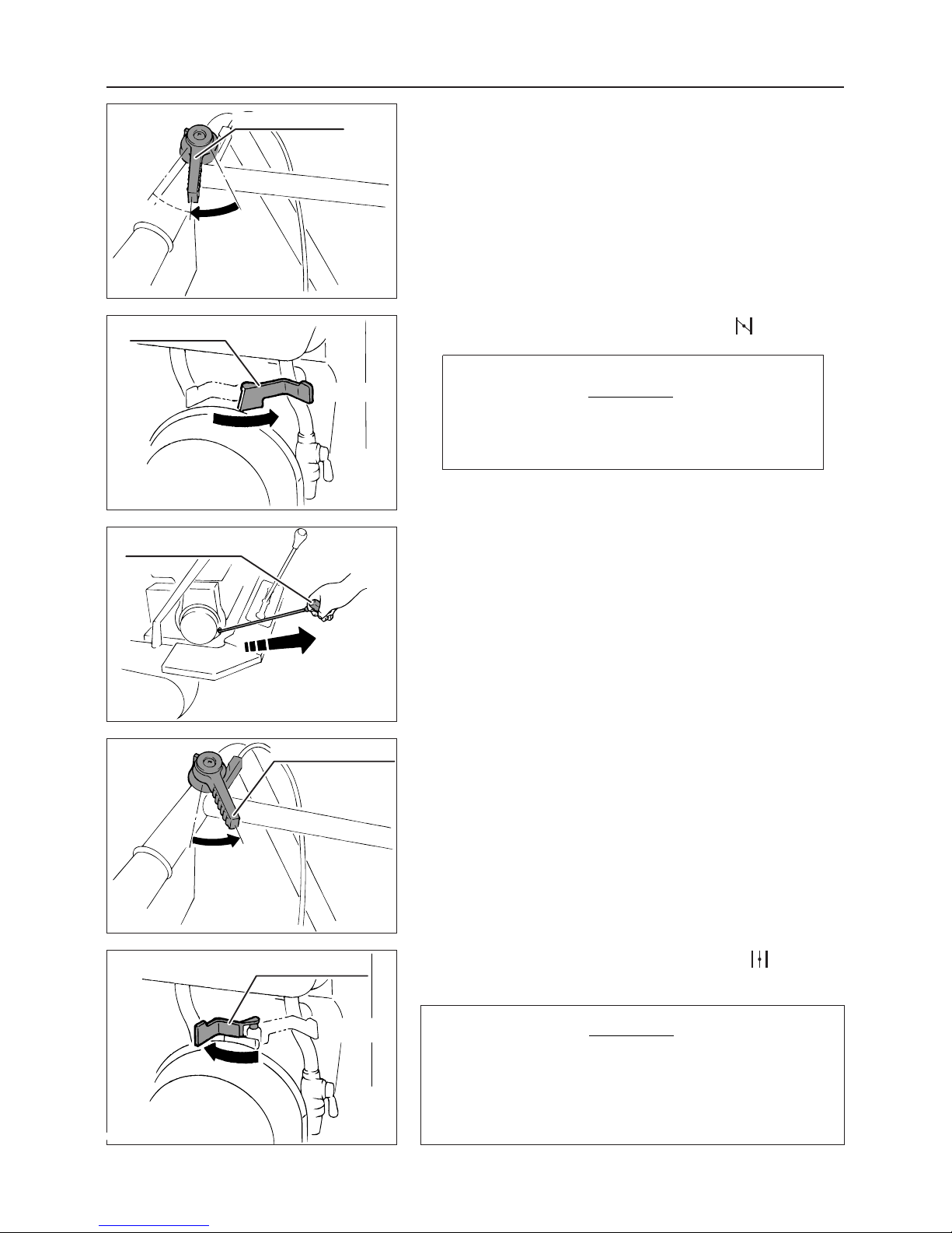
Choke lever
OPEN
CLOSE
Throttle lever
LOW
Starter knob
Choke lever
OPEN
CLOSE
Throttle lever
LOW
– 14 –
Operation
3560M-0602-050
3560M-0602-060
3560M-0602-080
3560M-0602-090
3560M-0602-070
4. Move the throttle lever to the halfway point between
"LOW" and "HI".
Reference:
The throttle lever of the vehicle is connected to the
throttle lever of the engine via a throttle cable.
5.
Move the choke lever to "FULL CLOSE( )" position.
The choke lever should not be operated after the
engine is warmed up.
NOTICE
6. Pull out the starter knob.
7. After the engine is started, move the throttle lever to the
"LOW" position.
8.
Return the choke lever to the "FULL OPEN ( )" position,
and perform the warm-up operation for 3 to 5 minutes.
・ The first week (about 40 to 50 hours use time) after
starting machine operation is the breaking-in period.
・ Do not apply excessive loads to the machine when
operating during this period.
NOTICE
Page 20
Drive clutch lever
Throttle lever
HI
LOW
Gear shift lever
– 15 –
Operation
When moving the vehicle backward, start the
vehicle slowly after sufficiently checking for safety.
WARNING
Drive clutch lever
3558M-0602-010
3558M-0603-020
3558M-0603-010
3560M-0603-030
6.3 Method of Operating
1. Check that all areas around the machine are safe.
2. Check that the drive clutch lever is in the "STOP" position.
3. Firmly move the gear shift lever to any forward or
reverse gear shift position.
Partially engaged gears may cause failures or
accidents. When the shift gears cannot be
fully engaged, do not force gears into positions. Move the drive clutch lever slightly to
the "RUN" position, then slowly repeat gear
shifting.
DANGER
4. Move the drive clutch lever slowly to the "RUN" position
to start the vehicle.
Do not move the drive clutch lever abruptly.
The engine may stall.
NOTICE
5. Adjust the speed by moving the throttle lever slowly
from "LOW" toward "HI" position.
Page 21
Side clutch lever (Right)
Side clutch lever (Left)
– 16 –
Operation
Gear shift lever
3558M-0603-010
3558M-0603-030
3558M-0603-040
5. After the vehicle is stopped, follow the steps 1 to 3 on
page 15. (For stopping the vehicle, refer to Section 6.4
"Stopping". p.17)
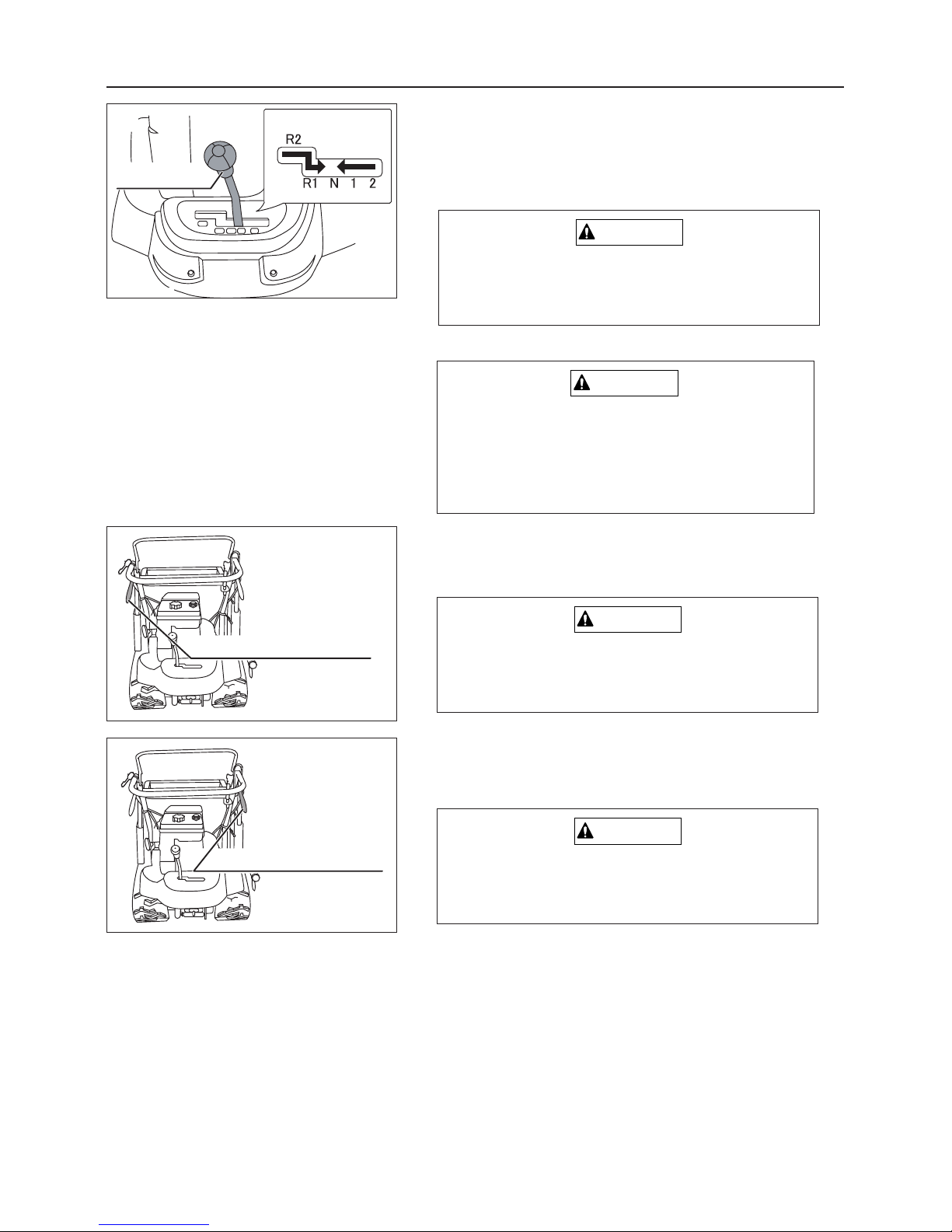
When Changing Speeds
Turning
Do not shift gears during traveling. Always stop
the vehicle before shifting gears.
CAUTION
If the side clutch levers on both right and left
sides are operated simultaneously, the vehicle will abruptly stop. Operate the right and
left side clutch levers at the same time only
in emergencies.
CAUTION
Right Turning
6. Grasp the right side clutch lever.
Avoid turning abruptly except for an emergency.
CAUTION
Left Turning
6. Grasp the left side clutch lever.
Avoid turning abruptly except for an emergency.
CAUTION
Page 22
Fuel cock
OPEN
CLOSE
Engine switch
Drive clutch lever
– 17 –
Operation
Throttle lever
LOW
3560M-0602-080
3558M-0602-010
3560M-0604-010
3560M-0604-020
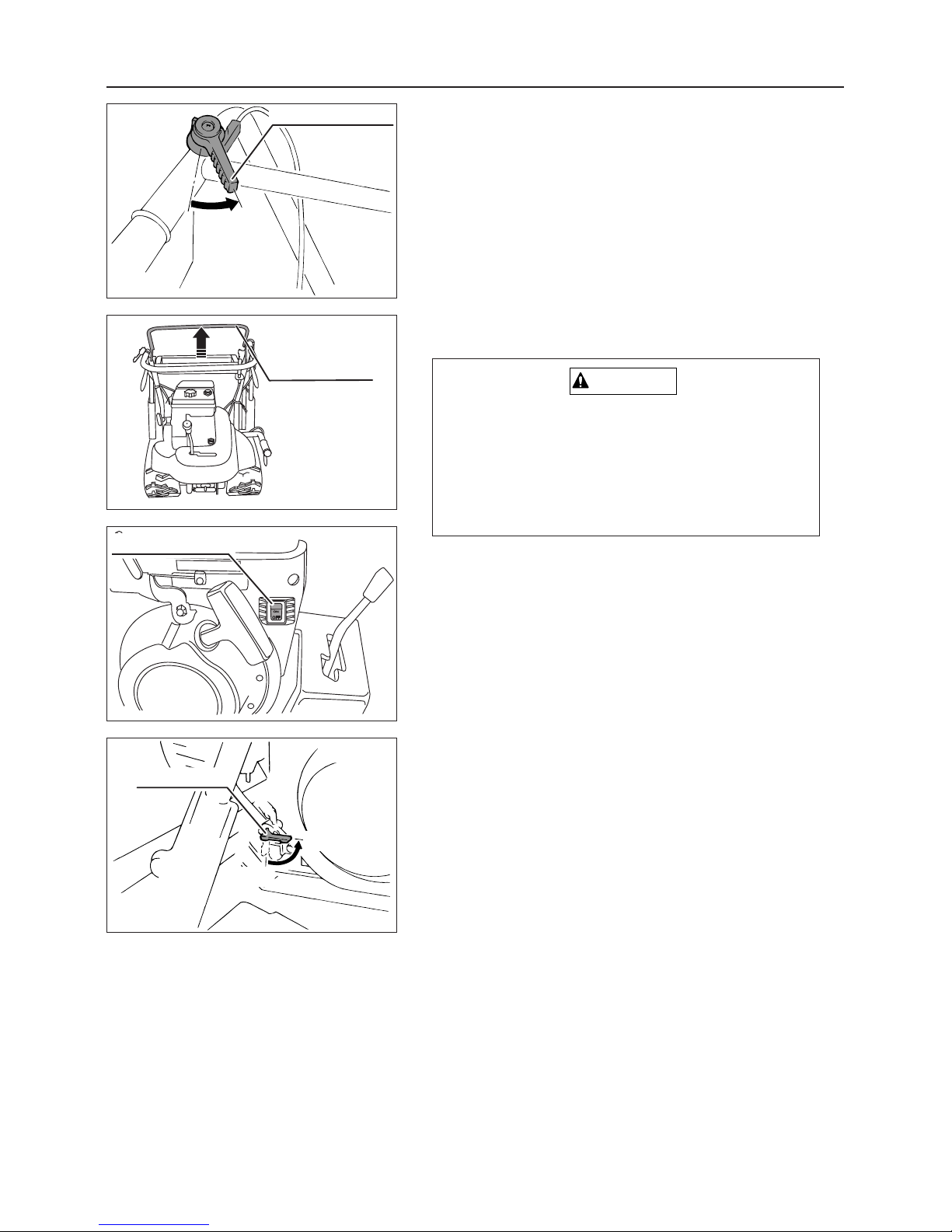
6.4 Stopping
1. Move the throttle lever to the "LOW" position .
2. Release the drive clutch lever to return it to the "STOP"
position.
In an emergency, grasp both right and left side
clutch levers simultaneously. The vehicle stops
urgently. On sloped ground, perform these operations carefully since the vehicle may rise from
the ground.
CAUTION
3. Move the engines switch to "OFF".
4. Turn the fuel cock to "CLOSE".
Page 23
Load deck support bar
– 18 –
Operation
3560M-0605-010
Dump lever
3558M-0605-010
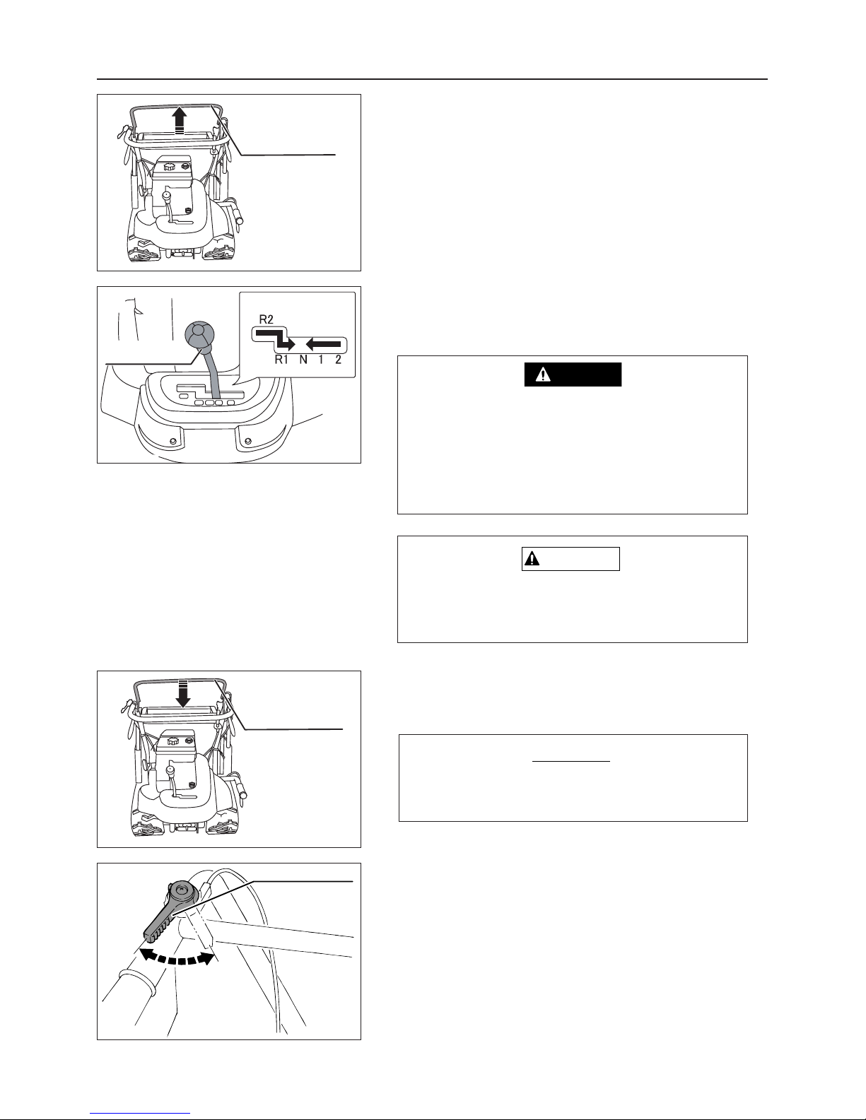
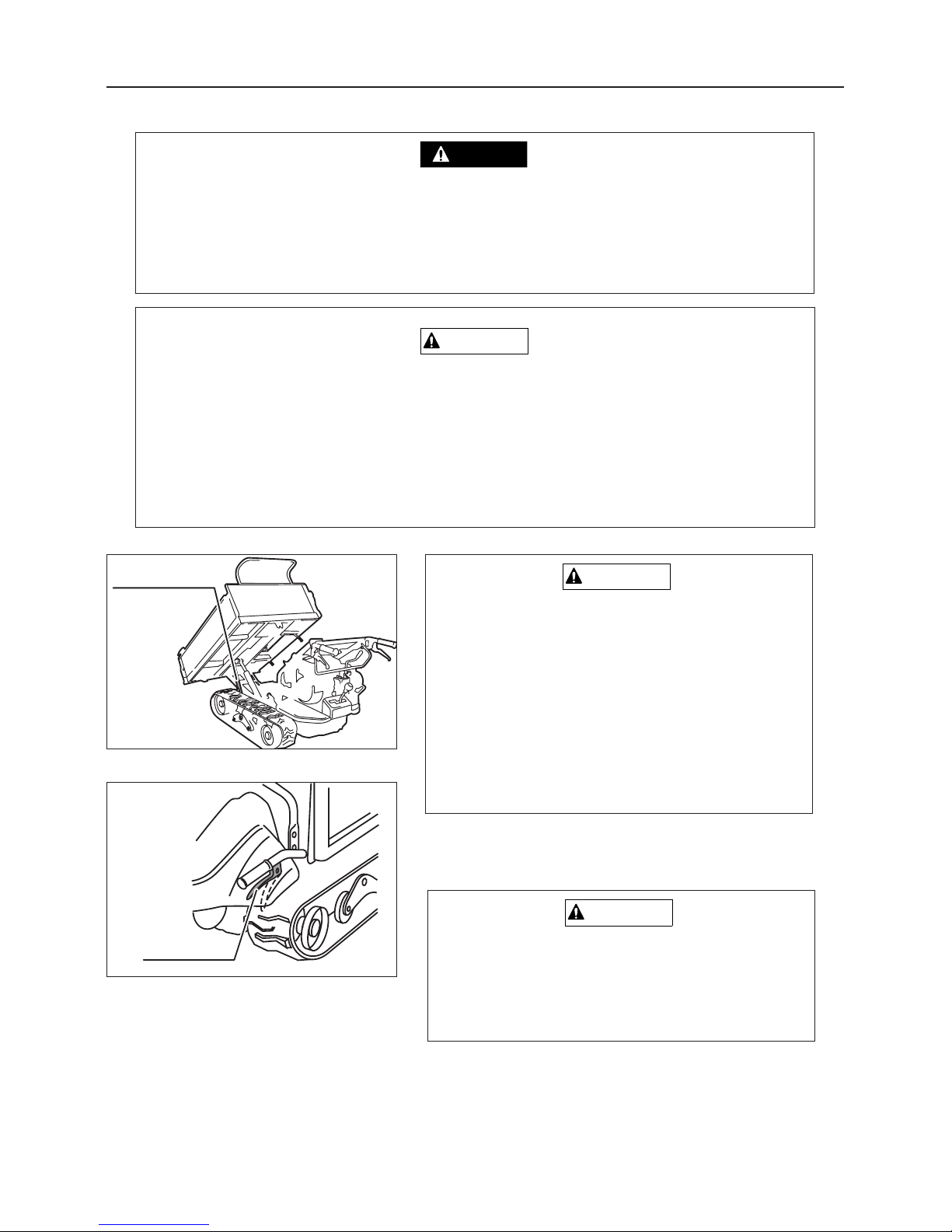
6.5 Operating Dump
• Falling load deck can cause injury or death
• Always fix load deck support bar before doing any work under the load deck
• Do not raise or lower load deck or dump load when anybody is standing near load
deck.
DANGER
•Avoid dumping on steep slopes.
• Raising or lowering the load deck on a steep slope can make the machine unstable,
causing it to shift suddenly or turn over, causing damage to the machine, injury or
death.
• If dumping on a slope is necessary, make the machine as level as possible by positioning on a large, immobile object such as a rock or fallen tree.
WARNING
•When performing the inspection operation under the deck, ensure to stop the
engine.
• Lowering the load deck suddenly with a
load can damage the machine chassis.
Always lower the load deck slowly to prevent damage to the machine chassis.
CAUTION
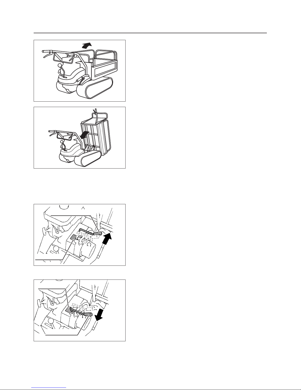
6.5.1 Operating Dump (Manual Dump)
Raising Dump Body
When the vehicle is positioned on a slope or
cargo is not placed uniformly but placed forward
in the deck, dumping may occur suddenly immediately after the deck is unlocked.
CAUTION
1. Grasp the dump lever to unlock the deck.
Page 24
– 19 –
Operation
Dump lever
Lock plate
RAISE
Dump lever
Lock plate
LOWER
3560M-0605-020
3560M-0605-030
3558M-0605-030
3558M-0605-020
2. Raise the deck in upper forward direction.
Lowering Dump Body
1. Manually tilt the deck backward until the deck is locked.
2. Raise the deck without operating the dump lever to
check that the deck is locked firmly.
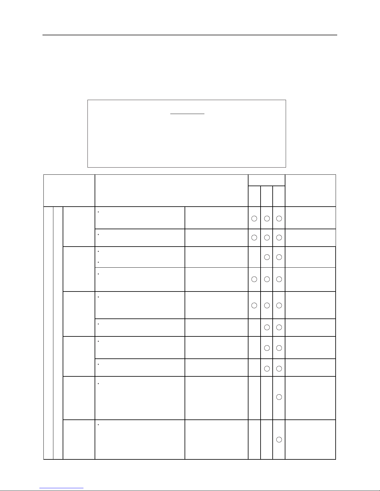
6.5.1 Operating Dump (Hydraulic Dump)
Raising Dump Body
1. Start the engine, move the throttle lever to the "HI"
position, and increase the engine speed.
2. Release the lock plate for the hydraulic dump lever.
3. Tilt the hydraulic dump lever to "RAISE" position.
4. When the dump body is raised to the upper limit,
a"hiss" sound is heard.
Quickly return the dump lever to the "NEUTRAL"
position.
Lowering Dump Body
1. Move the dump lever slowly to the "LOWER" posi-
tion.
2. When the dump body is raised to the lower limit,
a"hiss" sound is heard.
Quickly return the dump lever to the "NEUTRAL"
position.
Page 25
Maintenance
– 20 –
7. Maintenance
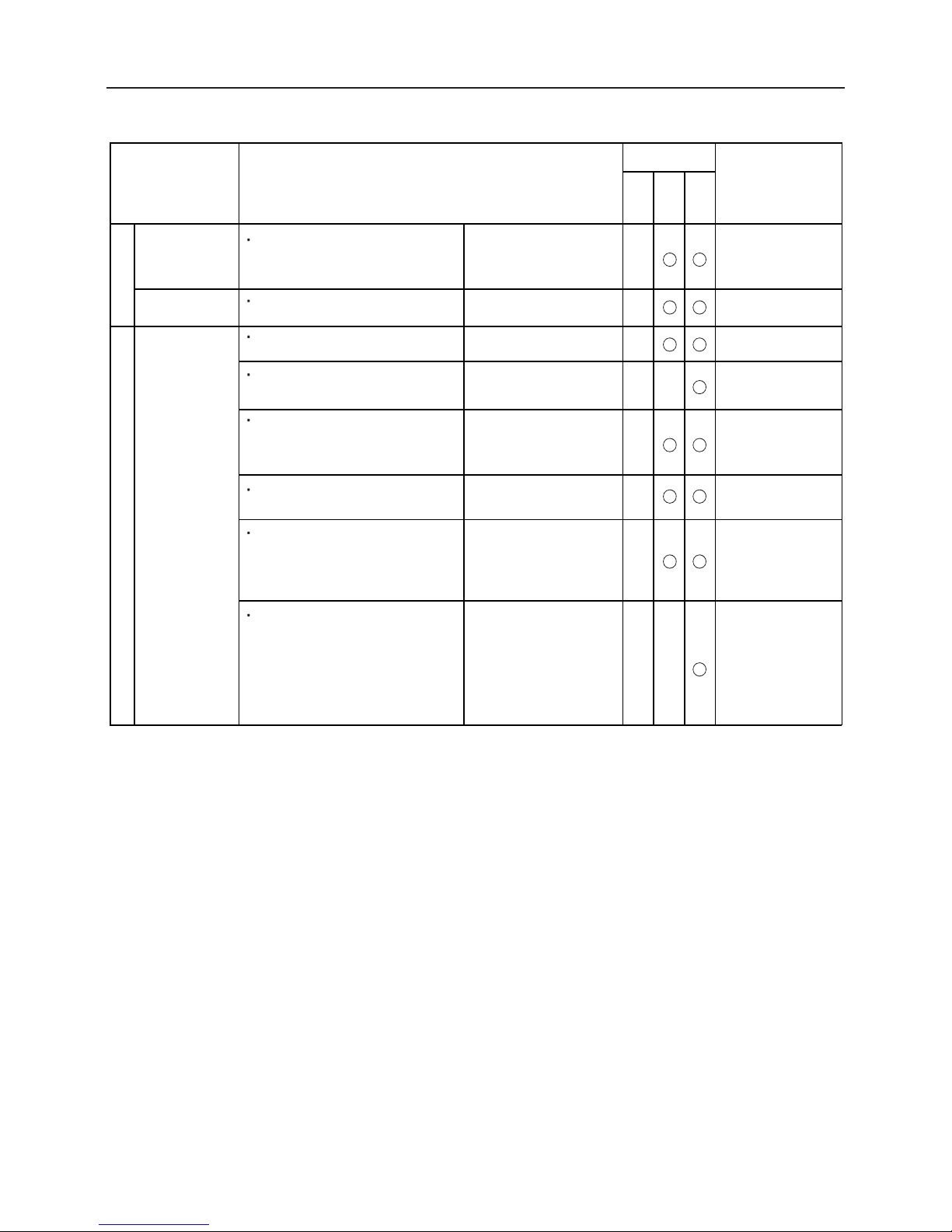
7.1 Periodic Inspection Table
Failure to carry out inspection and maintenance properly will cause machine failure.
Refer to the following table for inspection procedures and frequency.
Some inspection and maintenance procedures in the table
below require technical knowledge or specific tools and measuring instruments. If you have difficulty performing these procedures, or do not have the correct tools or instruments,
contact your dealer or a Canycom service center.
NOTICE
Item Content of inspection Remarks
Investigate starting condition of
engine and check for abnormal
noise.
There must be no catching,
stalling of engine,
or knocking.
Exhaust gas color and
exhaust sound must be
normal.
There must be no cracks,
deformation of case,
looseness of cover or
connecting piping.
There must be no gas
leakage.
The valve clearance must be
normal.
There must be no noticeable
dirt or damage.
Must work properly.
Must be at specified speed.
Must rotate smoothly.
Check for catching of accelerator
lever when accelerating engine,
engine stall, or knocking.
Check speed at low idling and at
high idling.
Check that rotation is smooth.
Warm up engine thoroughly, then
check for abnormal exhaust gas
color or exhaust sound, low idling to
high idling.
Check if glow plug works propery.
Check for cracks, deformation of
case, looseness of cover or
connecting piping.
Check for looseness of nuts and
bolts at tightening portion of
cylinder head and manifold
*If no leakage of gas or water is
found from these portions, this
check can be omitted.
Check for dirty or damaged element.
Check for gas leakage from exhaust
pipe or muffler.
Check the valve clearance
* When noise due to abnormal valve
clearance is absent and the engine is
running smoothly, this inspection may
be omitted.
Ease of
starting
Condition
of rotation
Exhaust
gas
condition
Air cleaner
Tightening
Valve
clearance
Engine
Engine proper
Inspection
interval
Inspection
interval
Monthly
Annually
Checks
before
starting
Please contact your
Canycom distributor
for inspection
Please contact your
Canycom distributor
for inspection
Cleaning/replacement:
See page 29 & 37
If gas or water leaks have
been found, check cylinder
head and manifold retaining nuts and bolts for
looseness.
Check that engine starts
smoothly and makes no
abnormal noises.
Page 26
Maintenance
– 21 –
Check for damaged or deteriorated
fuel hoses.
Check for dirty or clogged fuel
filter cartridge.
Cleaning: See page 30
There must be no dirt or
clogging.
There must be no wear or
carbon accumulation.
There must be no
dam
age
Fuel system
Drive clutch
V-belt
Transmission
Engine Power train
Item Content of inspection Remarks
Check for oil leakage from head
cover, oil pan, pipes, etc.
Check for loose or missing
mounting bolts or nuts.
Check oil level and dirt in oil
Please contact your
Canycom distributor
for inspection
Inspection/replacement:
See page 25
There must be no
marked oil leakage.
There must be no fuel
leakage.
There must be no loose
or missing mounting
bolts or nuts.
Oil level must be correct.
There must be no marked
Check the electrode for wear and
carbon accumulation.
Disengage the clutch while idling, and
check for abnormal noise.
Engage the clutch gradually to check
starting condition.
There must be no abnormal noise, and
the clutch must be disengaged.
Move the gear shift lever to the forward or
reverse gear shift position, and drive.
Check the transmission under operating
conditions for disengagement of gears,
abnormal noise, and abnormal heating.
Check the oil level in the case.
Check for fuel leakage from fuel
tank, injection pump, hoses, pipes.
Engine
compression
Engine
mount
Lubrication
system
Inspection
interval
Inspection
interval
Monthly
Annually
Checks
before
starting
Engine proper
If the engine is operating abnormally,
or if the exhaust condition at idle
or at high RPM is abnormal, check
the engine compression.
If you hear valve noise or
the engine is not running
smoothly, check valve clearance.
No cracks or deformities.Check engine base for cracks or
deformities.
Shift the gears, and check
the clutch for ease of
disengagement.
There must be no slippage,
and the disengagement must
be smooth.
Check the belt for cracking,
damage, and contamination.
The transmission must operate
normally, and no
disengagement of gears,
abnormal noise, or must occur
abnormal heating
The oil level must be normal.
Inspection/replacement:
See page 26
Inspection/replacement:
See page 26
Inspection:
See page 31
Adjustment:
See page 31
Adjustment:
See page 31
Inspection/cleaning:
See page 29
Ignition plug
Electrical
system
Check for oil leakage from the periphery
of the case.
Check oil for contamination.
There must be no excessive
contamination.
There must be no oil
leakage.
Page 27
Maintenance
– 22 –
Check for cracks, deformities,
wear.
Run the machine, and check the brake
for effectiveness.
Check that the brake can hold the unloaded
machine at a standstill on a sloped floor.
Move the lever back and forth repeatedly
to check pulling and returning states.
Check for oil leakage from around
axle.
Check for cut, deteriorated,
or worn rubber.
Check track tension.
Check for loose or missing
mounting
Drive machine and check for abnormal
noise or abnormal generation of
heat from shaft area.
Check for cuts or damage in steel
cord.
There must no loose or
missing mounting bolts
and nuts.
No abnormal noise or
heat.
There must be no oil
leakage.
Tension must not be too
loose or too tight.
There must be no cuts or
marked damage.
There must be no marked
cutting, deterioration, or
wear.
There must be no looseness
or rattling of connection
parts, or missing split pins.
No cracks, deformities, or
noticeable wear.
Sprocket,
idler,
roller,
upper roller
Crawler
Brake
Check for deformation and corrosion.
There must be no
deformation or corrosion.
The effectiveness must be
appropriate.
The effectiveness must be
appropriate.
The pulling and returning
states must be normal.
Track tension bolt
There must be no damage
or looseness.
Check the rods, links, and wires for
damage and the mounting parts for
looseness.
Operate the brake repeatedly to check for
looseness and rattling of connection parts
and missing split pins.
Rods, links,
and wires
There must be no rattling
or rusting.
Traction system Brake system
Item Content of inspection Remarks
Operate the lever to check for play
and pulling tolerance.
Operate the lever to check clearance
in rods, links, bearing sections, and
connection parts, and for rusting of
pins.
The play and pulling
tolerance must be
appropriate.
Inspection
interval
Inspection
interval
Monthly
Annually
Checks
before
starting
The side clutch must operate
correctly without generating
any abnormal noise.
Adjustment:
See page 34
Adjustment:
See page 32
Adjustment:
See page 32
Adjustment:
See page 33
Side clutch
Power train
There must be no cracks,
deformation, or wear.
Must operate smoothly.
Check that the deck can be moved vertically and
the gate can be opened and closed smoothly.
Check each part for cracks,
deformation, and wear.
Body / Loading
system
Deck and Gate
(Door, Sliding panel)
There must be no loose or
missing bolts.
There must be no excessive
play in the pin sections.
Check for loose or missing mounting
bolts.
Check the clearance of the frame to
truck bed mounting pins and dump
cylinder mounting pins by moving the
truck bed vertically.
Check that the side clutch functions correctly
without generating any abnormal noise
when the side clutch lever is operated
during traveling.
Page 28
Maintenance
– 23 –
Item Content of inspection Remarks
Inspection
interval
Inspection
interval
Monthly
Annually
Checks
before
starting
There must be no cracking or
deformation on the vehicle body
and cover, and no loose or
missing nuts and bolts.
Check the vehicle body and cover for cracking and
deformation. Also check bolts and nuts for looseness
and falling.
Body/
Loading system
Body
Safety stopper
Check for curvature or deformities.
No noticeable curvature or
deformities.
The bracket must be
installed properly, and there
must be no loose or missing
nuts and bolts.
Must be within reference
values.
There must be no
abnormal vibration,
abnormal noise, or
abnormal heating.
There must be no excessive
contamination of oil.
There must be no oil
leakage.
Check hose joints and seals for oil
leakage.
Operate the pump to check for
abnormal vibration, abnormal
noise, and abnormal heating in
unloaded and loaded conditions.
With the pump loaded, check for
delivery amount and delivery
pressure under loading.
* If any abnormality is not found in
the inspection of the previous item,
this inspection may be omitted.
Check the bracket for proper
installation, and bolts for loose or
missing nuts.
Check oil for contamination.
There must be no clog.
Check breather for clogging.
Hydraulic system
Hydraulic Pump
Power package
Please contact your
Canycom distributor
for inspection
Inspection/replacement:
See page 27
Page 29
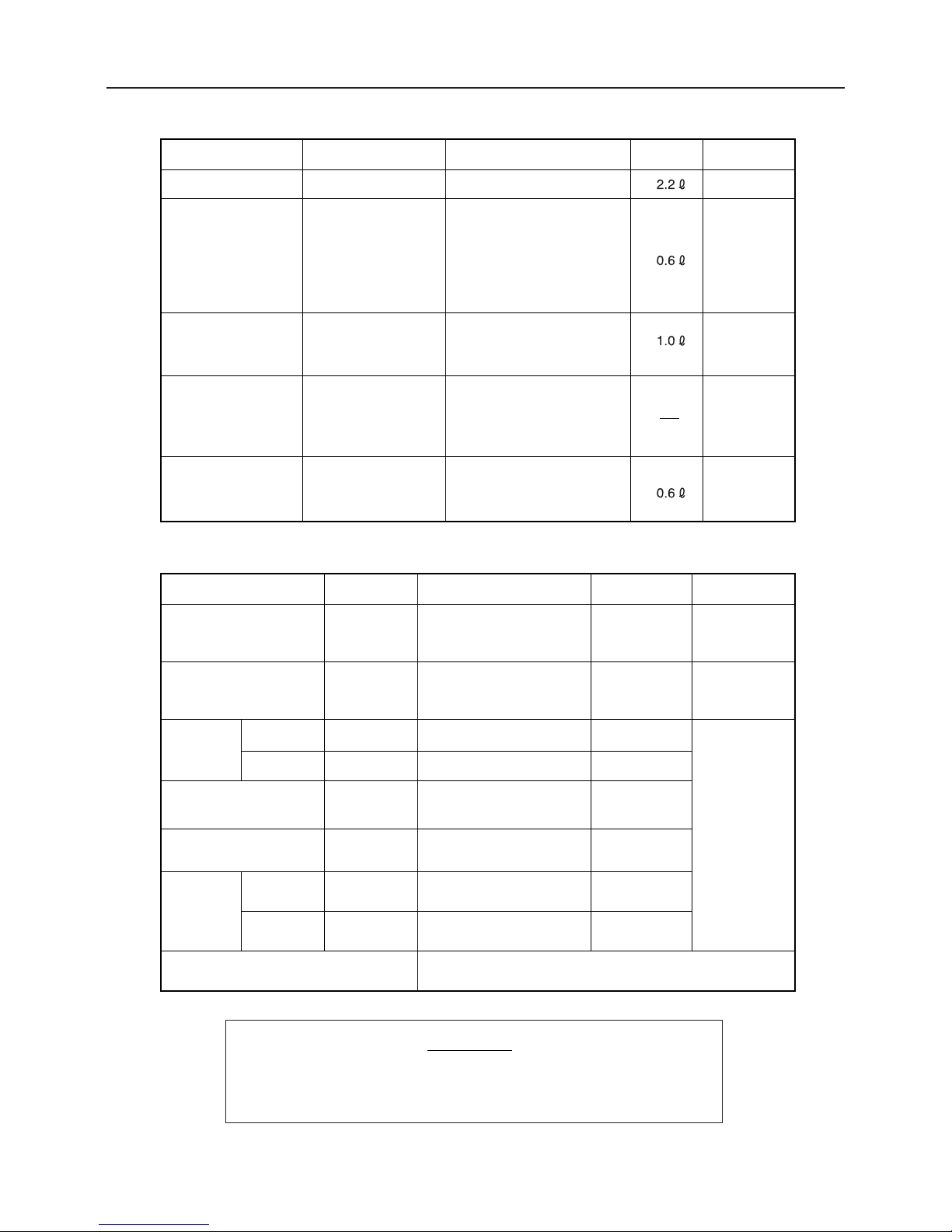
7.2 Fuel, Lubricant, and Coolant Chart
Maintenance
– 24 –
Filling: Check every
day, add when level
is low.
1st time: 50 hours
2nd time on: every
500 hours
Change:
1st time: 20 hours
2nd time on: every
100 hours
API category: SD class or
above
SAE category: 10W-30
Gear oil
(API category: GL4 or 5
SAE category: #80)
Item
Interval Recommended product Capacity
Page
Fuel Whenever needed Lead-free gasoline for cars
See page 12
See page 25
See page 26
Engine oil
Check every 100
hours, add when
level is low.
Turbine oil
(ISO: VG32)
(JIS: #90)
See page 28
See page 31
Transmission oil
Swing
Power package oil
(for hydraulic dump)
Chassis grease
Every six months
*No need for greasing
for the first 6 months
after purchase
Special replacement parts
Please contact your Canycom distributor (or our Service
Center).
Inspect every 50 hours
(weekly), and replace if
defective.
Inspect every 200 hours
(monthly), and replace if
defective.
Item
Replacement intervalQ'ty
Page
Parts number
Air cleaner element
Fuel filtter
08521300031
79531213100
35442021000
35496008000
35176021000
08520000019
See page 30
See page 30
1
1
2
1
1set
(The entire set is
replaced)
1
1
V-belt
Replace if defective.
Replace if defective.
Replace if defective.
One each on right and left sides
Every 2 years.
(Replace if defective)
Every 2 years.
(Replace if defective)
Replace if defective.
Brake lining
Travelling
Hydraulic
Upper side
of cylinder
Lower side
of cylinder
Please contact
your Canycom
distributor,
replacements.
Crawler
Hydraulic
hose
7.3 Replacement Parts Chart
Rubber parts such as hydraulic hoses will deteriorate even when
not used. Replace them every 2 years, or whenever damaged.
NOTICE
Page 30
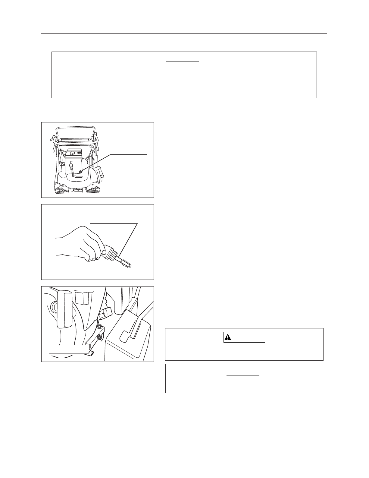
Drain plug
– 25 –
Maintenance
Dipstick
Oil filler plug
3558M-0601-020
3560M-0601-030
3560M-0704-010
Oil level must be maintained and proper oil must be used, for smooth rotation.
Improper maintenance and oil will cause failures and reduce the service of the
machine. Always use the specified high quality oil and maintain oil at proper levels.
NOTICE
7.4 Adding Oil
7.4.1 Engine Oil
Inspection/Adding
3. Replace the oil drain plug.
4. Open the oil filler cap, and pour in the specified oil.
(See item "Inspection/Adding" above.)
1. Remove the oil filler plug .
2. Visually check the engine oil level and the condition
of dirt in the oil. Add or remove oil until oil level is
between [F] and [L] lines on the dipstick. If the oil is
extremely dirty, change the oil.
Oil to use: See page 24.
Oil amount:
Between "F" and "L" on the dipstick.
3. Replace the fluid filler plug.
Dispose of the drained oil properly.
NOTICE
Changing
1. Prepare a suitable container to catch the drained oil.
2. Remove the oil drain plug to drain the oil from
the crankcase.
Avoid contact with high temperature oil to avoid burns.
CAUTION
Page 31
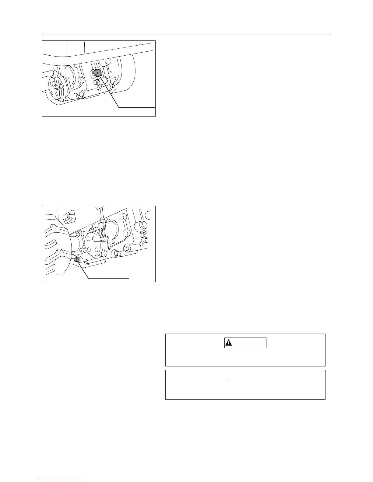
Drain plug
Fluid filler plug
– 26 –
Maintenance
3560M-0704-020
3560M-0704-030
3. Replace the drain plug.
4. Open the fluid filler plug, and add the specified fluid.
(See items "Inspection" and "Adding" above.)
Inspection/Adding
1. Remove the fluid filler plug.
2. Visually check the transmission fluid level and the
condition of dirt in the fluid. If the level is low, add
transmission fluid. If the fluid is extremely dirty,
change the fluid.
Oil to use: See page 24.
3. Replace the fluid filler plug.
Changing
1. Prepare a suitable container to catch the drained fluid.
2. Remove the drain plug to drain the fluid.
Note:
Fluid will drain faster with fluid filler plug removed.
Dispose of the drained oil properly.
NOTICE
Avoid contact with high temperature oil to avoid burns.
CAUTION
7.4.2 Transmission Fluid
Page 32
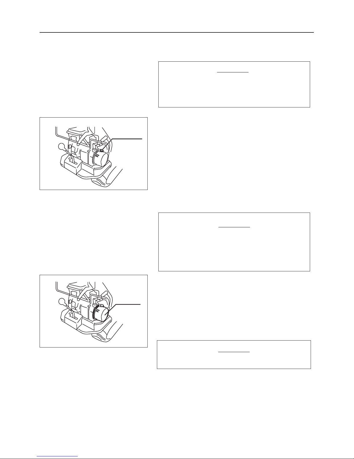
Oil tank
Fluid filler cap
– 27 –
Maintenance
3560M-0704-040
3560M-0704-050
Inspection/Adding
1. Remove the fluid filler cap.
2. Visually inspect the oil level. If oil is short, remove
the oil filler cap and replenish oil.
Fluid to use: See page 24.
3. Replace the fluid filler cap.
4. Start the engine to circulate the fluid
7.4.3 Hydraulic Pump Power Package Fluid
Low fluid levels may decrease dump performance. Check the fluid level every 100
hours.
NOTICE
When the engine is first started and the bed
of the truck is raised after adding fluid, knocking may occur due to entrapped air. To eliminate knocking, repeat above steps 2 to 3
times.
NOTICE
3. Replace the oil tank.
4. Open the fluid filler cap, and pour in the fluid.
(See item "Inspection/Adding Fluid" above.)
Dispose of the drained fluid properly.
NOTICE
1. Prepare a suitable container to catch the drained fluid.
2. Remove the oil tank mounting bolts, dismount the oil
tank, and drain oil.
Changing
Page 33
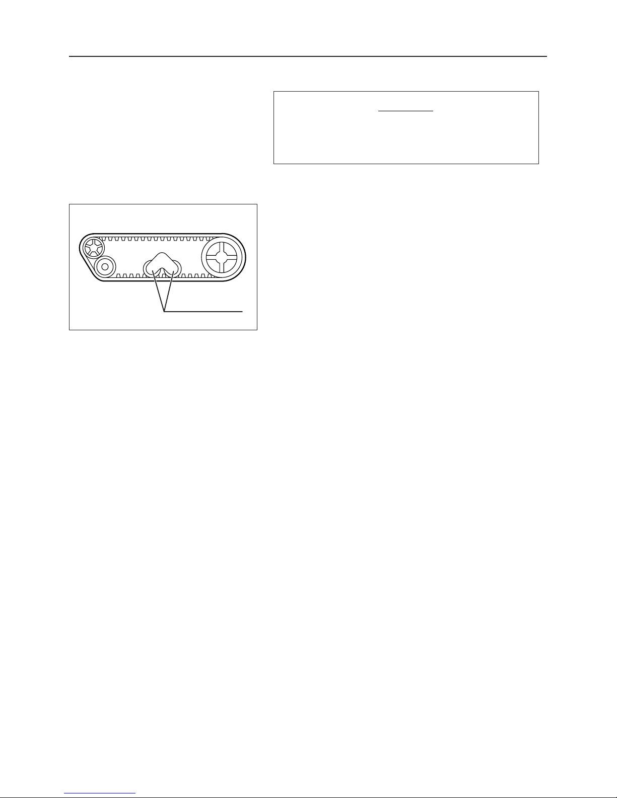
Roller(Swing)
– 28 –
Maintenance
3560M-0705-010
7.5 Lubricating
Proper Iubrication will prevent seizures and
rust, and ensure smooth operation.
Lubricate every 6 months.
NOTICE
1. Using a commercially available manual grease
pump or pneumatic grease pump, grease the areas
as shown in the figure.
Grease to use: See page 24.
Reference:
When a manual grease pump is used, strike it five to six
times. When the pump handle becomes heavy halfway,
stop greasing at once. When a pneumatic grease pump
is used, a few seconds are enough.
To lubricate swing, remove the outside nut, tighten the furnished grease fitting with a spanner, and apply grease to
the rollers through the grease fitting. After greasing,
remove the grease fitting, and tighten the nut firmly to the
shaft.
Page 34
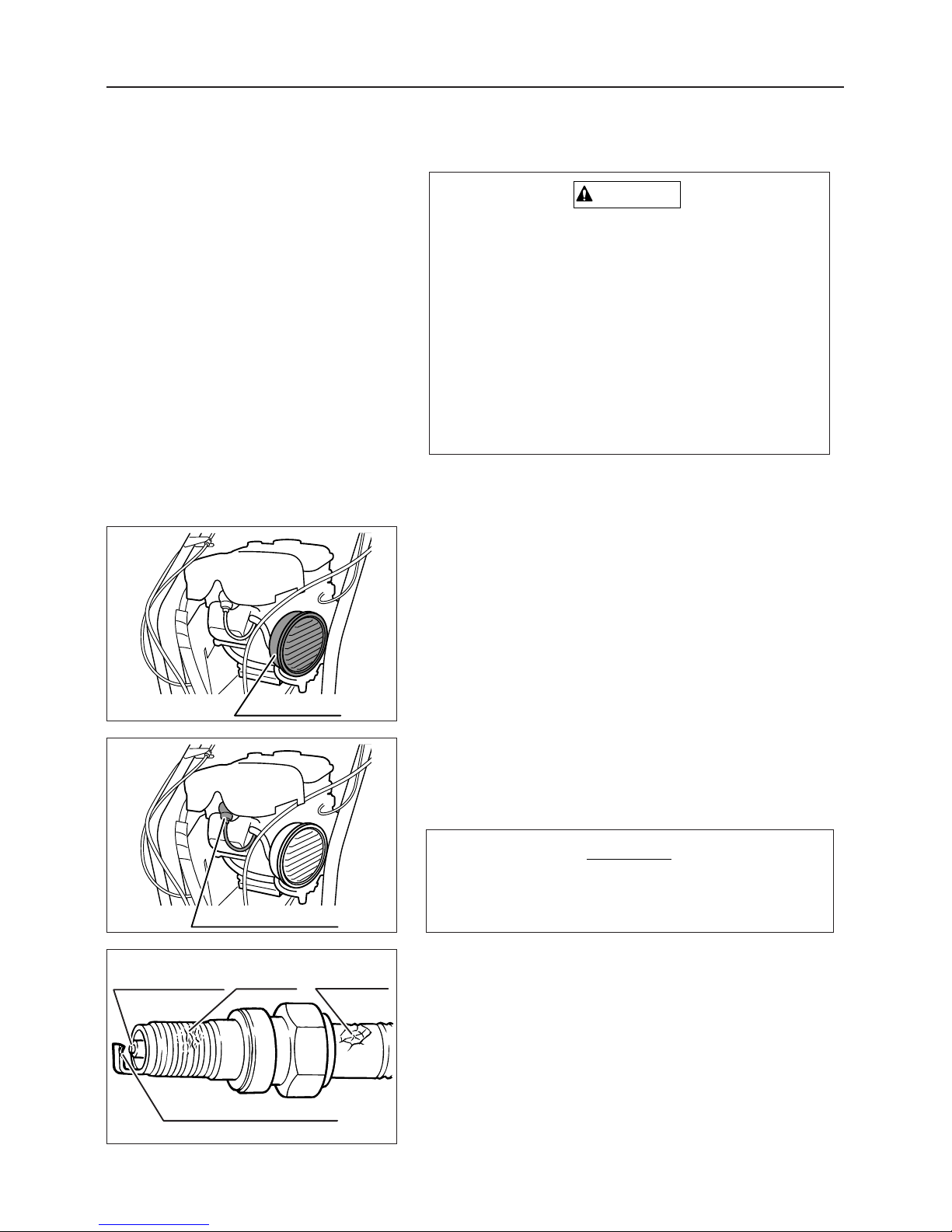
Ignition plug cap
Air cleaner
– 29 –
Maintenance
Degree of burning
Damage
Breakage
Wear, carbon deposit
3560M-0706-010
3560M-0706-020
3560M-0706-030
7.6 Cleaning
7.6.1 Air Cleaner Element
1. Remove the air cleaner cover.
2. Remove the air cleaner element.
3. Inspect and clean or replace the ignition plug by
referring to the "Engine Operation Manual" provided.
Changing / Replacing
7.6.2 Ignition Plug
Inspection
1. Remove the ignition plug cap.
2. Remove the ignition plug using a plug wrench.
3. Check the plug for the following points and clean or
replace it as necessary.
• Presence or absence of breakage of the insulator
•Worn electrode
• Carbon deposit
• Damage to and breakage of gasket
• Degree of burning of insulator in spark section
Do not pull on the cable when removing the ignition plug cap. Always hold the cap body.
NOTICE
•A dirty air cleaner element will reduce
engine performance and life. Clean every
50 hours of operation.
• Depending on the types of engines, air
cleaner elements of dry type, semi-wet
type, and oil bath type are available. The
cleaning method for air cleaner elements
varies from type to type. Consult the furnished "Engine Operation Manual" for correctly cleaning the elements.
CAUTION
Page 35
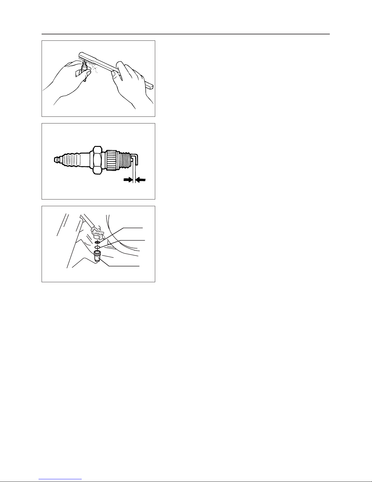
Filter
Packing
Filter pot
– 30 –
Maintenance
3560M-0706-040
3560M-0706-050
3560M-0706-060
Cleaning
1. Clean the ignition plug using a wire brush or plug
cleaner.
1. Grind the electrode with sandpaper to adjust the
gap as specified.
Standard clearance: 0.7 mm
3. Replace the ignition plug.
7.6.3 Fuel Cock (Fuel Filter)
Cleaning
1. Check that the fuel cock is positioned at "CLOSE".
2. Remove the fuel filter pot, and wash clean the inside
of the pot and the filter with kerosene.
Page 36
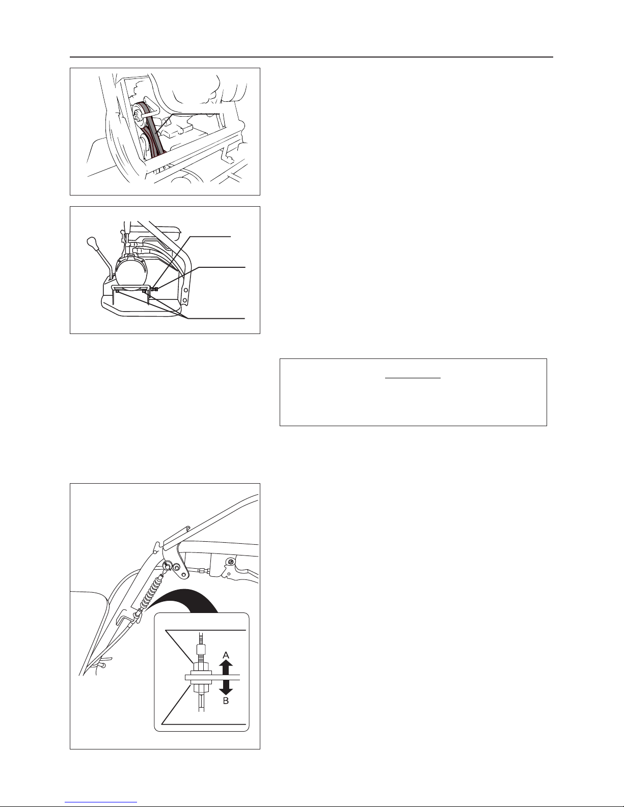
Lock nut
Adjustment nut
Lock nut
V-belt tension
adjustment bolt
Power package
mounting bolts
V-belt
– 31 –
Maintenance
3560M-0707-010
3560M-0707-020
3558M-0707-010
7.7 Adjustments
7.7.1 V-belt
Inspection (Engine V-belt)
1. Visually check the traveling V-belt for damage. If it
is damaged, replace.
Changing:
Contact your Canycom distributor.
Inspection (Power Package V-belt)
1.
Loosen the power package mounting bolts (4 pcs).
2. Loosen the lock nut for the V-belt tension adjustment bolt.
3. Turn the V-belt tension adjustment bolt to adjust the
V-belt tension so that the belt is deflected about 10
mm when the V-belt (between the pulleys) is
pressed at the center position by the finger.
Adjust the tension taking care so that the V-belt is
not slipped.
NOTICE
7.7.2 Clutch
1. Move the drive clutch lever to the "STOP" (lower
side) position to free the clutch wire.
2. Loosen the lock nuts of the turnbuckles.
3. Turn the adjustment nut to adjust the clutch wire.
・ If the clutch cannot be disengaged easily, turn
the adjust nut in direction (A).
・ If the V-belt slips, turn the adjustment nut in
direction (B).
4. After the adjustment, tighten the lock nut firmly.
(BP415)
Page 37
– 32 –
Maintenance
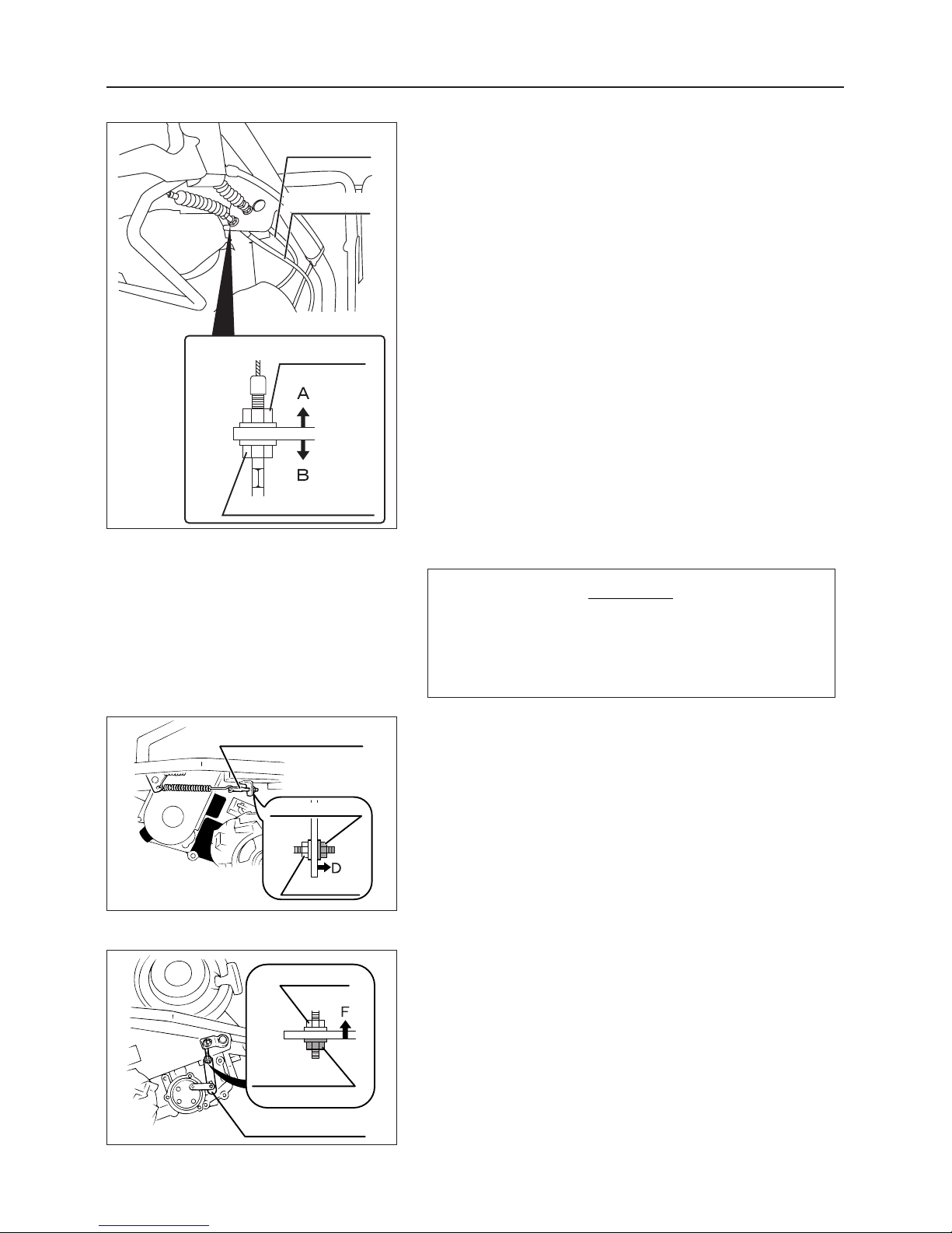
Brake wire
Locknut
Adjustment nut
Clutch wire
7.7.2 Clutch
1. Move the drive clutch lever to the "STOP" (lower
side) position to release the clutch wire.
2. Loosen the clutch wire lock nut.
3. Turn the adjustment nut to adjust the clutch wire.
・ If the disengagement of the running clutch is dif-
ficult, turn the adjustment nut in direction (B).
・ If the V-belt slips, turn the adjustment nut in
direction (A).
4. After the adjustment, tighten the lock nut firmly.
(BP416)
Brake adjuster E
Lock nut
Adjustment nut
Brake adjuster C
Lock nut
Adjustment nut
3560M-0707-040
3560M-0707-050
7.7.3 Brake
Proper brake performance is critical for safety.
Always keep brakes adjusted for maximum
performance.
NOTICE
1. Move the drive clutch lever to the "RUN" position to
disengage the brake.
2. Loosen the lock nut for the brake adjuster C.
3. Turn the adjustment nut to adjust the brake adjuster.
・ When the effectiveness of the brake is poor.
Turn the adjustment nut in D direction.
4. After the adjustment, tighten the lock nut firmly.
When the effectiveness of the brake is not sufficient
even after the adjustment above.
5. Loosen the lock nut for the brake adjuster E.
6. Turn the adjustment nut in F direction for adjustment.
7. After the adjustment, tighten the lock nut firmly.
(BP415)
3561M-0707-010
Page 38
– 33 –
Maintenance
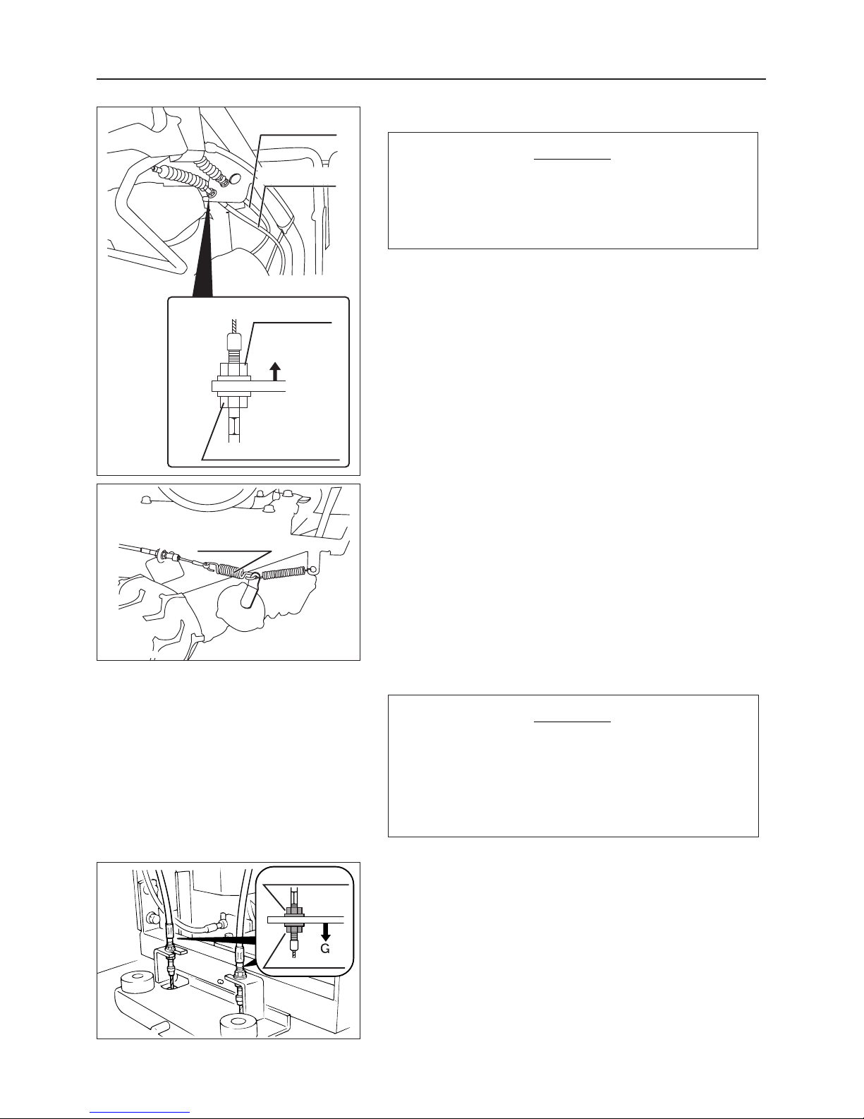
Lock nut
Adjustment nut
3560M-0707-060
7.7.3 Brake
If the effectiveness of the brake is lowered,
adjust it immediately even if it is very small so
that safety can be assured at all times.
NOTICE
1.
Move the drive clutch lever to the "RUN" position to
release the brake.
2.
Loosen the brake wire lock nut.
3. Turn the adjustment nut to adjust the brake wire.
・ When the effectiveness of the brake is low:
Turn the adjustment nut in the arrow direction so
that the spring connecting the transmission to
the brake wire is extended by about 5 mm with
the running clutch lever set to "STOP (lower
side)".
4. After the adjustment, tighten the lock nut firmly.
7.7.4 Side Clutch
When the amount of play of the side clutch lever
becomes large or when turning cannot be done
smoothly, adjust the amount of play by means
of the adjustment screw for the side clutch
cable.
NOTICE
1. Loosen the lock nut for the side clutch cable.
2. Turn the adjustment screw in G direction to adjust
the play of the side clutch lever.
Play of side clutch lever:
1 to 5 mm (at lever holder)
3 After the adjustment, tighten the lock nut firmly.
(BP416)
Brake wire
Lock nut
Adjustment nut
Clutch wire
Spring
3561M-0707-030
3561M-0707-020
Page 39
– 34 –
Maintenance
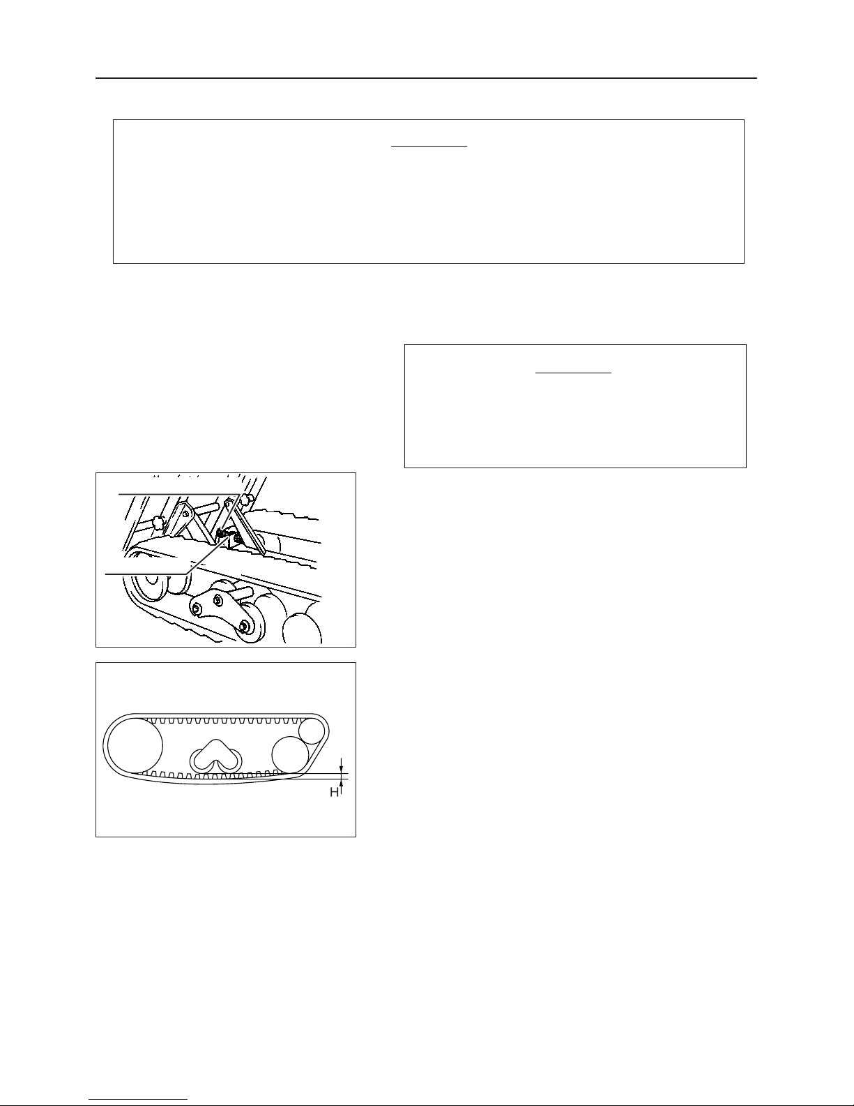
Crawler tension bolt
Lock nut
3560M-0707-070
3560M-0707-080
Loose track tension can cause the tracks to come off the machine, causing damage to the
machine and possibly serious injury or death to the operator or bystanders.
During the first 100 hours of use, the tracks stretch and the track tension loosens.
Check track tension during the preoperation inspection and as part of monthly inspections,
as specified in the Regular Inspection Chart.
NOTICE
1. Jack up the front and rear of the chassis to raise the
crawler on one side and make it horizontal to the
ground surface.
Perform this step with extra care so that the jack
does not move from the specified positions.
NOTICE
7.7.5 Track Tension
2. Raise the deck (See page 19).
3. Loosen the lock nut of the crawler tension bolt.
4. Rotate the crawler tension bolt to adjust the clearance
(H in the figure) between the crawler and the lowest
part of the rollers to 10 to 15 mm.
5. Lower the deck (See page 19).
Page 40
– 35 –
Maintenance
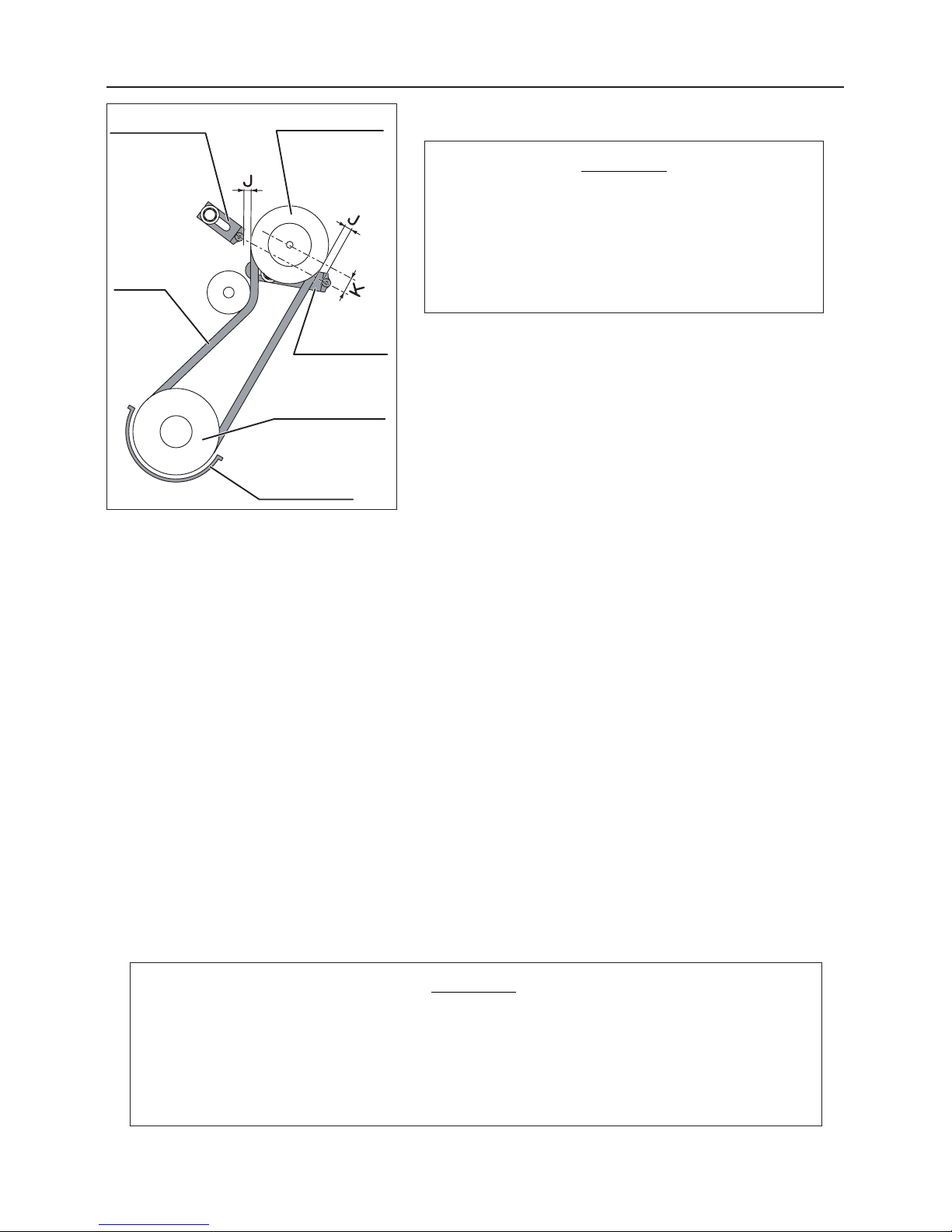
Belt stopper
Belt stopper
Belt stopper
V-belt
Engine pulley
Transmission pulley
3560M-0707-090
・ If the drive clutch is not disengaged completely,
the belt stopper may be maladjusted. When the
belt stopper is removed for the replacement of
the belt, adjust it as follows.
・
Stop the engine during the adjustment.
NOTICE
7.7.6 Belt stopper
1. Remove the safety cover .
2. With the drive clutch lever positioned at "RUN", set
the clearance (J) between the traveling V-belt and
the belt stopper to about 5 to 6 mm, and the clear
ance (K) to about 10 to 20 mm. (With the drive
clutch lever positioned in "RUN", assure a clearance
of 5 mm or more between the belt stopper and the
other belt. )
3. Set the belt stopper on the transmission pulley side
so that the clearance of it from the belt is uniformized all around the periphery of it.
7.8 Maintenance After Use
Maintenance After Use in Normal Conditions
・ After using the machine, remove any mud, water, or other foreign matter stuck to the machine.
Do not wash the engine or control panel with water. This will allow water to enter and lead to rust.
・ When leaving the machine outdoors, cover it with a waterproof cover.
Maintenance After Use in Cold Weather
・ After using the machine, remove any mud, water, or other foreign matter stuck to the machine.
Then park the machine on concrete or firm dry ground, or set it on blocks. If water or mud stuck
to the machine freezes, it may cause failure.(In extremely cold areas, put wooden blocks under
the crawlers at right angles to the machine.)
・ When leaving the machine outdoors, cover it with a waterproof cover.
If the machine freezes and it is impossible to operate, do not try to move it by force.
Use warm or hot water to melt the frozen parts or wait for the ice to melt.
Be careful when moving the machine.
If the machine is moved by force, Canycom does not take responsibility for damage
or failure.
NOTICE
Page 41
– 36 –
Storage (Long-term Storage)
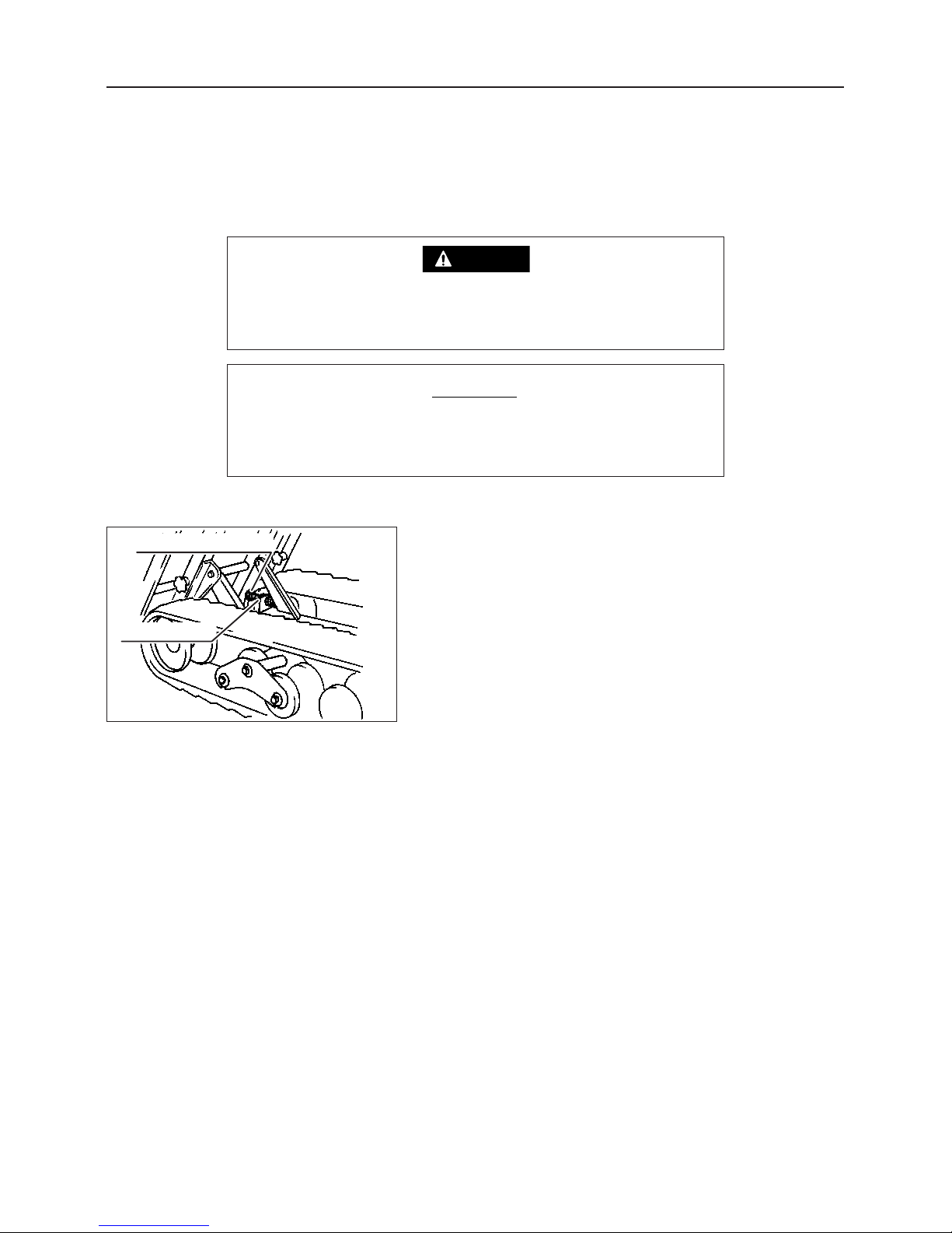
Crawler tension bolt
Lock nut
3560M-0707-070
8. Storage (Long-term Storage)
Do not store this machine, the battery, or fuel in a place where
there is a flame or where the temperature is high. There is a
danger of fire.
DANGER
Avoid storing the machine in a place where there is high
humidity or excessive dust. When storing, wait for the engine
to cool down, then cover the machine with a waterproof sheet.
NOTICE
When storing for a long time,it is necessary to take suitable action to prepare for the next time that
the machine is used. When preparing for long-term storage, carry out "Maintenance after use" (see
page 35), then do as follows.
8.1 Machine
1. Loosen the crawler tension bolts (See Page 34).
2. Clean the outside surface of the machine with an oily
cloth, then lubricate the rotating and sliding parts.
3. Place a board under the crawler.
4. Position the clutch lever at "STOP", and chock the
crawler.
Page 42
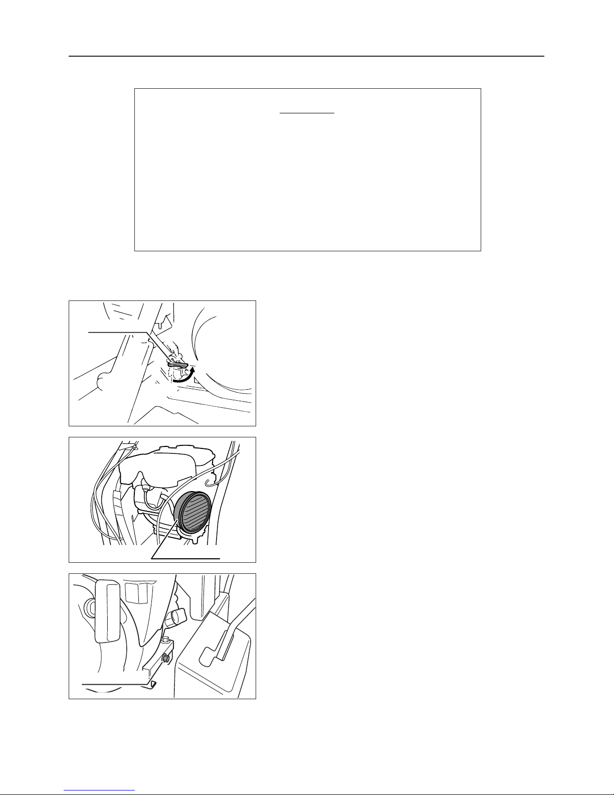
Fuel cock
OPEN
CLOSE
– 37 –
Storage (Long-term Storage)
Air cleaner
Drain plug
3560M-0604-020
3560M-0606-010
3560M-0704-010
• If fuel is left in the carburetor for a long period, it will deteriorate, and problems with starting and rotational fluctuation may
occur. To prevent these problems, when storing the engine for
a long period, drain the fuel in the carburettor and the fuel tank.
Do not use fuel which has been left for a long period.
• For details about engine storage, refer to the furnished "Engine
Operation Manual" provided.
NOTICE
8.2 Engine
1. Remove the air cleaner element and clean it.
(See page 28)
8.2.3 Replacing Engine Oil
8.2.1 Fuel Cock
1. Turn the fuel cock to the "CLOSE" position to cut off the
fuel supply.
8.2.2 Cleaning Air Cleaner Element
1. Drain the engine oil, then fill with fresh engine oil. (See
page 25)
Page 43
Troubleshooting
– 38 –
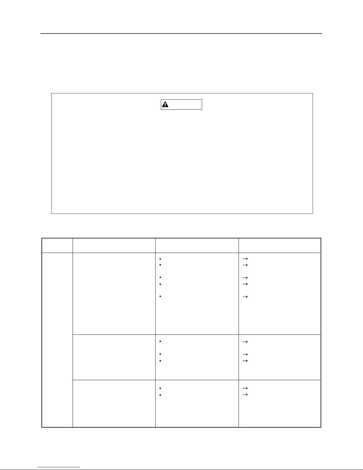
9. Troubleshooting
Some repairs require specialized service knowledge or equipment, as indicated in the
Troubleshooting Chart. In these cases, contact your dealer for repair, adjustment, or part
replacement.
Troubleshooting Chart
If a machine malfunctions or has abnormal operation, stop using the machine immediately.
Using the machine when it is malfunctioning or operating abnormally could injure or kill
the operator or bystanders, or damage the machine.
Use the information in the Troubleshooting Chart to fix the problem. When troubleshooting
procedures involve fuel, oil or other mechanical fluids, or the battery, take all appropriate
safety precautions. Follow all safety precautions for using and inspecting the machine, as
appropriate for a given troubleshooting procedure.
If you can not resolve the problem or do not have the correct tools or knowledge,
take the machine to your dealer or Canycom service center for repair, adjustment, or
part replacement.
WARNING
Location
Engine
related
Problem Main causes Remedy
Engine does not start or is
difficult to start
Add fuel (See page 12)
Wait for a while before
starting
Add fuel (See page 25)
Clean or replace (See page
29)
Follow procedure in 6.2
"Method of starting" and
try to start again. If the
engine still cannot be
started, please contact your
Canycom distributor
Open the fuel cock (See
page 13)
Add fuel (See page 12)
Return the choke (See
page 14)
Fuel cock not open
No fuel
Failure to return choke
Engine stops immediately
No fuel
Excessive fuel flow
Engine oil is low
Defective ignition of ignition
plug due to contamination or
insufficient sparking
Other
Add fuel (See page 12)
Inspect and add oil (See
page 25)
Out of fuel
Seizure caused by lack of
engine oil or by deterioration
of oil
Engine suddenly stopped
Page 44
Troubleshooting
– 39 –
Please contact your
Canycom distributor
Defective idling
(variation in engine speed)
Location
Engine
related
Problem Main causes Remedy
Lack of output or
acceleration
Abnormal noise or vibration
from engine or around
engine
Looseness of V-belt
Defective adjustment of
accelerator
Overload
Looseness of screw Inspect and further
tighten.
Adjust
Please contact your
Canycom
distributor
Reduce load
After inspecting, adjust
oil level (See page 25)
Change fuel
Check and repair ( please
contact your Canycom
distributor )
Defective compression
Clogged air cleaner
Failure to return choke
Engine oil level is too
high
Improper fuel
Worn cylinder, piston ring
Large amounts of black
smoke are emitted (defective
exhaust condition)
White smoke or blue
smoke is emitted
(defective exhaust
condition)
Excessive consumption of
engine oil
Leakage of engine oil Check and repair
Add oil (see page 25)
Engine overheats Lack of engine oil
Check and repair ( please
contact your Canycom
distributor )
Clean or replace (See page
29)
Check and repair ( please
contact your Canycom
distributor )
Clean or replace (See page
29)
Return the choke
Excessive consumption of
fuel
Leakage of fuel from fuel
system
Clogged air cleaner
Replace
(please
contact your
Canycom distributor)
Replace
(please
contact your
Canycom distributor)
Throttle lever is catching
Throttle cable broken or
rusted
Throttle lever deformed or
malfunctioning
Page 45
Troubleshooting
– 40 –
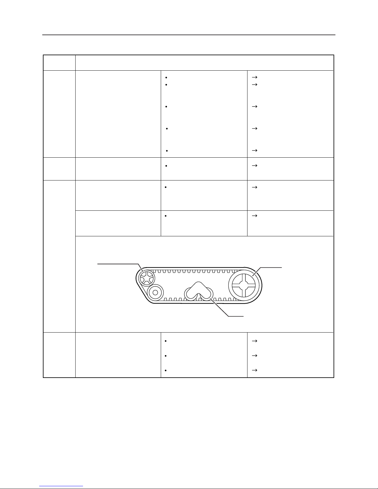
Location
Power
transmission
system
Problem Main causes Remedy
Clutch disengagement is
bad
Improper adjustment
Adjust (See page 31)
The V-belt slips when the
clutch is let in
Improper adjustment
Adjust (See page 31)
Abnormal noise is made
near the transmission
Damaged gear or worn
bearing
Please contact your
Canycom distributor
Gears cannot be shifted
Improper adjustment of
clutch
Damaged gear or worn
bearing
Adjust (See page 31)
Please contact your
Canycom distributor
Gears disengage
Gears not smoothly
shifting
Worn gear
Excessive loading
Firmly shift gears
Please contact your
Canycom distributor
Reduce loading
The side clutch is loose
Improper adjustment
Adjust (See page 33)
Turning cannot be done
smoothly
Improper adjustment
Adjust (See page 33)
Shift the gears completely
The brake is applied.
Adjust the brake (See page 32)
Engage the V-belt, or adjust
(
please contact your
Canycom distributor
)
Please contact your
Canycom
distributor
Vehicle will not move even
when the clutch is engaged
Gears are not shifted
completely
The vehicle does not move even
when the clutch is engaged.
V-belt disengaged or
excessively loosened
Failure of transmission
Page 46
Troubleshooting
– 41 –
Brake
Crawler
Poor braking
Adjust nut loosened
Brake lining worn
Oil in brake drum
Water in brake drum
Overload
Adjust (See page 31)
Replace the lining
(Please contact your
Canycom distributor)
Replace the oil seal
(Please contact your
Canycom distributor)
Apply the brake several
times to eliminate water
in the brake drum
Reduce the oveload
Crawler does not turn
smoothly
Improper adjustment
Adjust (See page 34)
Location
Roller,
upper
roller,
and
idler
Lift and
dump
system
Problem Main causes Remedy
Replace the defective
part (Please contact your
Canycom distributor)
Replace the defective
part (Please contact your
Canycom distributor)
Add or replace (See page
27)
Inspect and repair
Adjust
(See page 35)
The dump or lift
equipment does not
operate, or mal-functions.
Oil in the power package is
short or deteriorated.
Oil leakage from hydraulic
system
Belt tension not sufficient
Defective bearings
Defective bearings
Discontinuous noise
Abnormal heating
Idler
Sprocket
Roller
Page 47
Transporting Machine
– 42 –
10. Transporting Machine
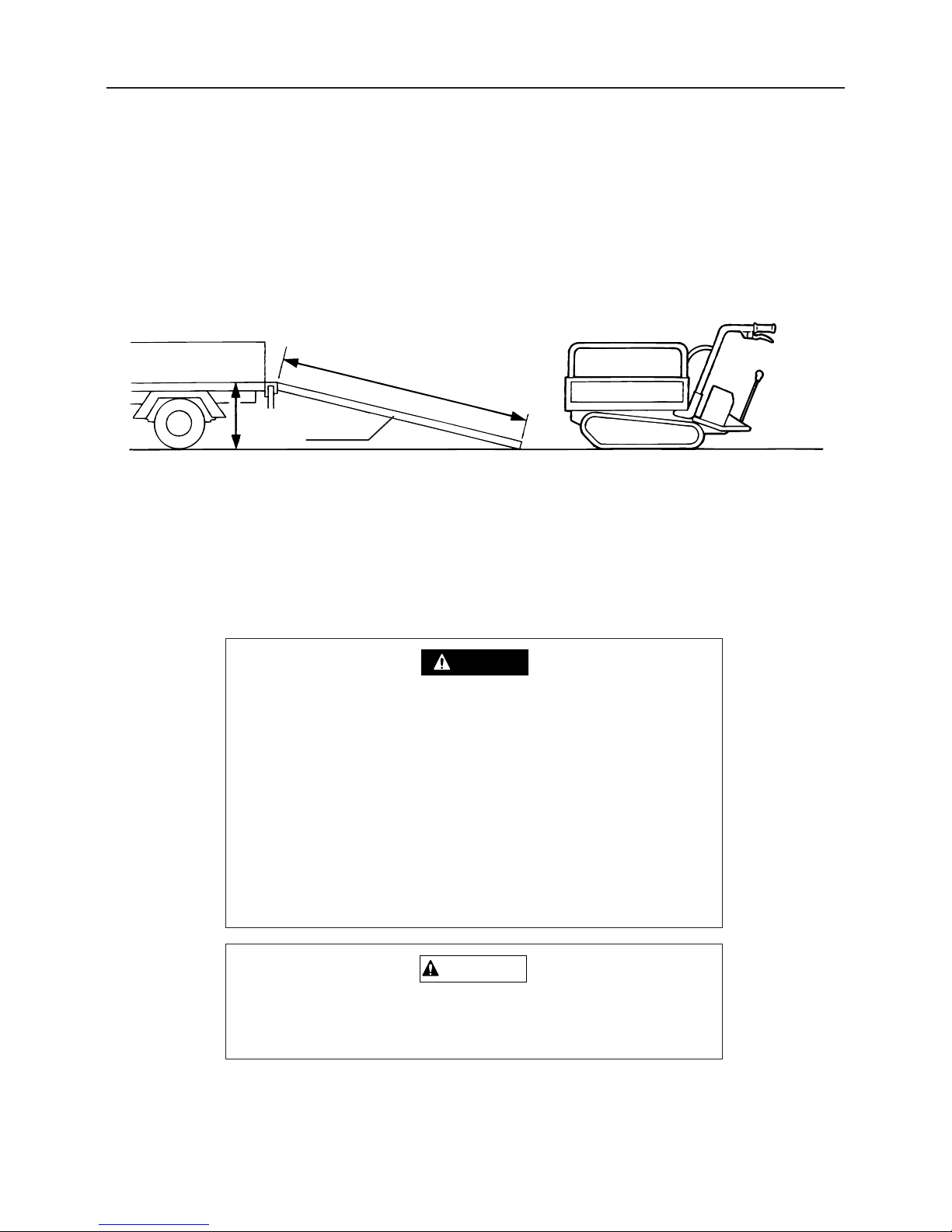
When loading and unloading this machine onto a truck for transportation, follow these safety
precautions.
1. Use ramps that have ample strength (that can hold the total weight of the machine and operator),
width (at least 1.2 times the width of the crawler), and length (at least 3 times the height of the bed
of the truck), and are fitted with no-slip pads. Choose a place where the ramps will not bend under
the weight of the machine.
2. Fit the hooks of the ramps to the bed of the truck so that they do not slip and so that there is no
height difference from the bed of the truck.
Height
Ramp
Length of 3 tim
es height or longer
3560M-1000-010
• When loading and unloading the machine, do not allow any-
one to come near the machine or the ramps.
• Do not change direction on the ramps. There is a danger
that the machine will fall off.
• When driving up the ramps, shift the gear shift lever to the
forward 1st position, and when driving down, shift it to the
reverse 1st position, then travel slowly.
DANGER
The gravity center of the machine may suddenly shift, when
crossing from the ramps into the bed of the truck.
CAUTION
Page 48
Accountable receipt of guarantee certificate
Based on the instruction manual for the following product I have purchased, I have been given
guidance and explanations as to the safe operation as well as handling and control and I have
received this guarantee certificate.
Address
Customer
(Signature)
Name
Model
Product
name
purchased
Production
number
Remarks
Dealer (Duplicate)
Delivery
(Person in charge)
inspection
Dealer
Explainer
Date of explanation
Person who
received
explanations
Dealer name
Page 49
※ The back is the guarantee certificate.
Customer (Duplicate)
Accountable receipt of guarantee certificate
Based on the instruction manual for the following product I have purchased, I have been given
guidance and explanations as to the safe operation as well as handling and control and I have
received this guarantee certificate.
Address
Customer
(Signature)
Name
Model
Product
name
purchased
Production
number
Remarks
Delivery
(Person in charge)
inspection
Dealer
Explainer
Date of explanation
Person who
received
explanations
Dealer name
Page 50
Guarantee certificate
Thank you very much for purchasing our company's product this time.
We guarantee the product you have purchased as shown below.
1. Period of guarantee: Shall be one year counting from the
date of delivery.
2. Details of guarantee: Only if a defect in design and
manufacturing is found in the parts, materials, etc. which
constitute this machine during the period of guarantee and
our company acknowledges this defect, we will replace or
repair the part in question, free of charge,at our company's
authorized dealer, agricultural cooperative association, or its
designated service factory.
3. Exclusion of application: Even during the period of guarantee,
we will not provide guarantee in the following cases.
(1) A case where a failure results from carelessness in use
and handling, negligence, or imperfection checking
(2)A case where a failure results from the use in which the
limit of the specifications specified by our company is
exceeded
(3) A case where a modification or alteration which is not
approved by our company causes a failure
(4) A case where a failure results from the use of parts other
than our company's genuine parts
(5) A case where a failure results from repair which is done
somewhere other than our company's authorized dealer,
agricultural cooperative association, or its designated
service factory
(6) A case where failure determination materials are
insufficient and the damaged part is lost.
(7) Consumable parts
(8) When the guarantee certificate is not presented, you may
have to pay the cost.
(9) Even if the guarantee certificate is lost, we will not reissue
it.
CHIKUSUI CANYCOM, INC.
90-1 Fukumasu, Yoshii-machi,
Ukiha gun, Fukuoka, Japan
Page 51
Memo of address and telephone number
(Name of dealer)
■
Sales Headquarters
09437(5)2195 FAX (5)4396
■
Tokyo Headquarters
03(3552)6255 FAX (3552)6288
■
Foreign Trade Center
03(3552)6255 FAX (3552)6288
■
Sendai Center
022(281)1255 FAX (281)3141
■
Saitama Center
0495(77)4511 FAX (77)4511
■
Osaka Center
0790(42)6031 FAX (42)6035
■
Hiroshima Center
0824(34)5996 FAX (34)5997
■
Matsuyama Center
0899(83)2701 FAX (83)5749
■
Fukuoka Center
09437(6)2583 FAX (5)5126
■Kagoshima Center 0995(58)3011 FAX (58)2344
CHIKUSUI CANYCOM, INC.
We prohibit unauthorized reprinting and reproduction of this document.
 Loading...