


MODEL NO. 068-7827-2
ASSEMBLY INSTRUCTIONS
Toll-free 1-888-670-6684
IMPORTANT: Please read this manual carefully before beginning assembly of this product.
Keep this manual for future reference.
ANDERSON CREDENZA

2
MODEL NO. 068-7827-2
Important Safety Instructions 2
Parts List 3-6
Assembly 7-31
Warranty 32
IMPORTANT SAFETY INSTRUCTIONS TABLE OF CONTENTS
Warning! To reduce the risk of serious injury, read the following safety
instructions before assembling and using the dining table.
• This product is intended for domestic indoor use only.
• The product should be placed on a flat horizontal surface.
• Arrange necessary manpower when assembling or moving the product.
• Do not push furniture, especially on a carpeted fl oor. Have someone help you lift heavy items and set it
in place.
• Check all screws periodically for tightness. When required, tighten them again.
Needed for Assembly
Hammer
2 people
No. 2 Phillips Screwdriver
Tip Shown Actual Size

3
PARTS LIST
Right End - 1
A
Left End
- 1
B
Upright - 1
C
Top - 1
D
Bottom - 1
E
Back Rail
- 1
F
Skirt - 4
H
Shelf
- 1
J
Left Front/Right Rear Foot - 2
L
Brace - 2
G
Back - 1
I
Right Front/Left Rear Foot - 2
K

MODEL NO. 068-7827-2
4
Center Foot - 2
M
Door
- 2
N
Top Drawer Front - 1
O
Drawer Front - 2
P
Top Right Drawer Side - 1
Q
Top Left Drawer Side - 1
R
Top Drawer Back - 1
T
Left Drawer Side - 2
V
Drawer Back - 2
X
Drawer Brace - 2
Y
Top Drawer Bottom - 1
S
Right Drawer Side - 2
U
Drawer Bottom - 2
W
PARTS LIST

5
Extension Rail - 6
1
Extension Slide - 6
2
Extension Set shown separated
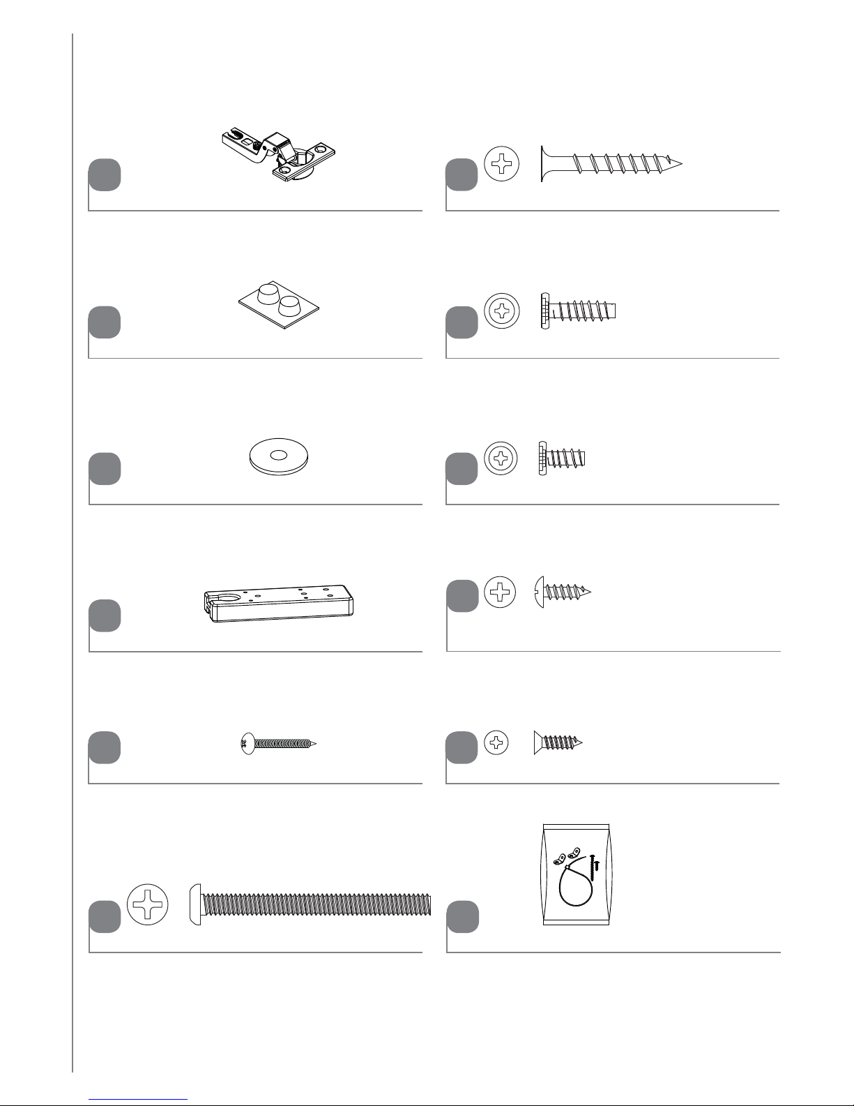
Large Hidden Cam- 38
3
Small Hidden Cam - 12
4
Angled Head Cam Screw - 38
5
Straight Head Cam Screw - 12
6
Short Wood Dowel - 4
8
Metal Pin/Rubber Sleeve Set - 4
10
Angled head
Straight head
Hinge Bracket - 4
12
Long Wood Dowel - 40
7
Cover Card - 1
9
Drawer Bracket Set - 2
11
PARTS LIST

MODEL NO. 068-7827-2
6
Bumper - 2
Ballast - 1
16
14
13
15
Washer
- 4
Hinge - 4
Nail - 48
Black 1-1/2" Flat Head Screw - 30
19
17
18
Black 2-9/16" Bolt - 4
Black 1/2" Wafer Head Screw - 4
Silver 1/2" Flat Head Screw - 8
23
21
20
22
Black 1/2" Pan Head Screw - 36
Black 13/16" Wafer Head Screw - 6
99
Furniture Tipping Restraint Kit - 2
PARTS LIST

ASSEMBLY
D
Step 1
Requires D, 5, 7
NOTE: Two people are needed to build this unit.
Turn two ANGLED CAM SCREWS (5) into the TOP (D).
Insert four LONG WOOD DOWELS (7) into the short edges of the TOP (D).
7
Rounded edge
7
7
Surface with more holes
5
Angled head
Angled head
5 7

8
MODEL NO. 068-7827-2
Step 2
Requires D, F, 7, 19
Insert three LONG WOOD DOWELS (7) into the BACK RAIL (F).
Fasten the TOP (D) to the BACK RAIL (F). Use four BLACK 1-1/2" FLAT HEAD SCREWS (19).
NOTE: Be sure the LONG WOOD DOWELS in the BACK RAIL insert into the TOP.
7
D
F
7 19
19
Surface with larage holes
Surface with CAM SCREWS
ASSEMBLY

9
Step 3
Requires E, 5, 7
Turn fourteen ANGLED CAM SCREWS (5) into the exact holes shown in the BOTTOM (E).
Insert six LONG WOOD DOWELS (7) into the short edges of the BOTTOM (E).
E
Angled head
5 7
Surface with more holes
Finished edge
5
7
7
Angled head
ASSEMBLY

10
MODEL NO. 068-7827-2
Step 4
Requires H, K, L, M, 3, 5, 7
Turn four ANGLED CAM SCREWS (5) into the exact holes shown in the FEET (K, L, and M).
Insert four LONG WOOD DOWELS (7) into the FEET (K, L, and M).
Insert two LONG WOOD DOWELS (7) into the SKIRTS (H).
Insert four LARGE HIDDEN CAMS (3) into the SKIRTS (H).
Fasten two SKIRTS (H) to the FEET (K, L, and M). Tighten four LARGE HIDDEN CAMS.
NOTE: Be sure the LONG WOOD DOWELS in the FEET insert into the SKIRTS.
Repeat this step for the remaining SKIRTS (H) and FEET (K, L, and M).
H
H
Angled head
5 73
321
The arrow must
point toward the
edge of the board.
3
3
K
M
L
7
5
5
Angled head
ASSEMBLY

11
Step 5
Requires E, H, K, L, M, 3, 7
Insert six LONG WOOD DOWELS (7) into the FEET (K, L, and M).
Insert fourteen LARGE HIDDEN CAMS (3) into the SKIRTS (H) and FEET (K, L, and M).
Fasten the SKIRTS (H) and FEET (K, L, and M) to the BOTTOM (E). Tighten fourteen
LARGE HIDDEN CAMS.
NOTE: Be sure the LONG WOOD DOWELS in the FEET and SKIRTS insert into the BOTTOM.
73
321
The arrow must
point toward the
edge of the board.
3
E
Finished edge
H
H
K
L
K
M
L
H
H
M
3
7
ASSEMBLY

12
MODEL NO. 068-7827-2
Step 6
Requires A, B, 1, 5, 12, 22
Turn twelve ANGLED CAM SCREWS (5) into the exact holes in the ENDS (A and B).
Fasten two HINGE BRACKETS (12) to the RIGHT END (A). Use the four SCREWS in the
HINGE BRACKETS.
Separate the EXTENSION SLIDES (2) from the EXTENSION RAILS (1) as shown in the
diagram. Be prepared, the parts are greasy.
Fasten three EXTENSION RAILS (1) to the LEFT END (B). Use nine BLACK 1/2" PAN
HEAD SCREWS (22).
NOTE: For each EXTENSION RAIL, turn a SCREW into the holes shown in the diagram.
Then, slide the inner cartridge of the EXTENSION RAIL in to fi nd the other two holes that
line up with the holes in the LEFT END. Turn the SCREWS into those holes.
NOTE: The EXTENSION SLIDES will be used later for the DRAWERS.
B
A
Angled head
51
12
22
Push the black lever up and pull the SLIDE from the RAIL.
12
Use these holes.
Open end
1
1
1
5
12
Curved edge
Open end
Curved edge
22
ASSEMBLY

13
7
Step 7
Requires C, 1, 5, 7, 12, 22
First, fasten two HINGE BRACKETS (12) to the UPRIGHT (C). Use the four SCREWS in
the HINGE BRACKETS.
Then, fl ip the UPRIGHT over.
Turn two ANGLED CAM SCREWS (5) into the exact holes in the UPRIGHT (C).
Insert fi ve LONG WOOD DOWELS (7) into the short edges of the UPRIGHT (C).
Fasten three EXTENSION RAILS (1) to the UPRIGHT (C). Use nine BLACK 1/2" PAN
HEAD SCREWS (22).
NOTE: For each EXTENSION RAIL, turn a SCREW into the holes shown in the diagram.
Then, slide the inner cartridge of the EXTENSION RAIL in to fi nd the other two holes that
line up with the holes in the LEFT END. Turn the SCREWS into those holes.
Angled head
51
12
22
5
12
C
C
7
Open end
22
7
F
L
I
P
O
V
E
R
Finished edge
ASSEMBLY

14
MODEL NO. 068-7827-2
Step 8
Requires C, D, 3
Insert two LARGE HIDDEN CAMS (3) into the UPRIGHT (C).
Fasten the UPRIGHT (C) to the TOP (D). Tighten two LARGE HIDDEN CAMS.
NOTE: Be sure the LONG WOOD DOWELS in the UPRIGHT insert into the TOP.
3
321
The arrow must
point toward the
edge of the board.
3
C
D
F
3
Unfi nished edge
Surface with CAM SCREWS
Surface with HINGE BRACKETS
ASSEMBLY

15
Step 9
Requires E, 19
Fasten the BOTTOM (E) to the UPRIGHT (C). Use two BLACK 1-1/2" FLAT
HEAD SCREWS (19).
NOTE: Be sure the LONG WOOD DOWELS in the UPRIGHT insert into
the BOTTOM.
C
E
Unfi nished edge
19
19
Do not stand the unit upright
without the BACK fastened.
The unit may collapse.
Caution
ASSEMBLY

16
MODEL NO. 068-7827-2
Step 10
Requires A, 3, 8
Insert two SHORT WOOD DOWELS (8) into the FEET (K and L).
Insert fi ve LARGE HIDDEN CAMS (3) into the TOP (D), BOTTOM (E), and BACK RAIL (F).
Fasten the RIGHT END (A) to the TOP (D), BOTTOM (E), and BACK RAIL (F). Tighten
fi ve LARGE HIDDEN CAMS.
NOTE: Be sure the SHORT WOOD DOWELS in the FEET insert into the RIGHT END.
D
F
8
E
A
3
321
The arrow must
point toward the
edge of the board.
3
8
L
K
8
3
Curved edge
ASSEMBLY

17
C
Step 11
Requires G, 3, 7
Insert four LONG WOOD DOWELS (7) into the ends of the BRACES (G).
Insert two LARGE HIDDEN CAMS (3) into the BRACES (G).
Fasten the BRACES (G) to the UPRIGHT (C). Tighten two LARGE HIDDEN CAMS.
NOTE: Be sure the LONG WOOD DOWELS in the BRACES insert into the UPRIGHT.
73
321
The arrow must
point toward the
edge of the board.
3
7
Unfi nished edge
G
G
3
Surface with holes
ASSEMBLY

18
MODEL NO. 068-7827-2
Step 12
Requires B, 3, 8
Insert two SHORT WOOD DOWELS (8) into the FEET (K and L).
Insert seven LARGE HIDDEN CAMS (3) into the TOP (D), BOTTOM (E), BACK RAIL (F),
and BRACES (G).
Fasten the LEFT END (B) to the TOP (D), BOTTOM (E), BACK RAIL (F), and BRACES (G).
Tighten seven LARGE HIDDEN CAMS.
NOTE: Be sure the WOOD DOWELS in the BRACES and FEET insert into the LEFT END.
83
321
The arrow must
point toward the
edge of the board.
3
D
F
E
B
8
K
L
8
3
Curved edge
G
G
ASSEMBLY

19
17
Step 13
Requires I, 15, 16, 17, 18
Unfold the BACK (I) and lay it over your unit.
Make equal margins along all four edges of the BACK (I). Push on opposite corners of
your unit if needed to make it "square".
Fasten the BACK (I) to your unit using the NAILS (17).
NOTE: Do not tap NAILS into the BACK RAIL (F).
NOTE: Be sure to tap NAILS into the holes that line up over the UPRIGHT (C).
NOTE: Perforations have been provided for access through the BACK. Carefully cut out
the holes needed.
Fasten the BALLAST (16) to the BOTTOM (E) exactly as shown. Use four WASHERS (15)
and four BLACK 2-9/16" BOLTS (18).
1615
18
Do not stand the unit upright
without the BACK fastened.
The unit may collapse.
Caution
Unfi nished surface
These holes must line up
over the UPRIGHT (C).
Do not use this
hole in this step.
Do not use this
hole in this step.
16
15
18
F
I
These two holes
should be here.
E
17
ASSEMBLY

20
MODEL NO. 068-7827-2
Step 14
Requires Q, R, 2, 22
Fasten two EXTENSION SLIDES (2) to the TOP DRAWER SIDES (Q and R). Use six
BLACK 1/2" PAN HEAD SCREWS (22).
R Q
2
22
2
Use these holes.
Open end
22
Open endOpen end
Angled edge
22 22
ASSEMBLY

21
Step 15
Requires Q, R, S, T, 19
Fasten the TOP DRAWER BOTTOM (S) to the TOP DRAWER BACK (T). Use four BLACK
1-1/2" FLAT HEAD SCREWS (19).
Fasten the TOP DRAWER SIDES (Q and R) to the TOP DRAWER BOTTOM (S) and TOP
DRAWER BACK (T). Use eight BLACK 1-1/2" FLAT HEAD SCREWS (19).
T
Unfi nished edge
19
S
Unfi nished surface
T
S
R
Q
Angled edge
19
ASSEMBLY

22
MODEL NO. 068-7827-2
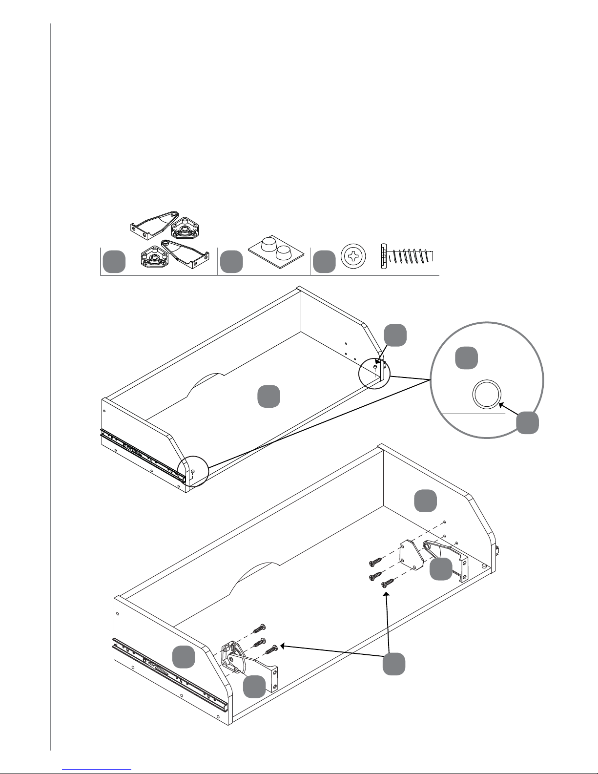
Step 16
Requires 11, 14, 20
Peel the BUMPERS (14) from the card and place one in each front corner of the TOP
DRAWER BOTTOM (S).
Fasten the DRAWER BRACKET SETS (11) to the TOP DRAWER SIDES (Q and R) exactly
as shown. Use six BLACK 13/16" WAFER HEAD SCREWS (20).
11
S
R
Q
S
14
14
20
11
11
20
14
ASSEMBLY

23
Step 17
Requires O, 21
Fasten the TOP DRAWER FRONT (O) to the DRAWER BRACKET SETS (11). Use four
BLACK 1/2" WAFER HEAD SCREWS (21).
O
21
Curved edge
11
21
ASSEMBLY

24
MODEL NO. 068-7827-2
Step 18
Requires U, V, 2, 22
Fasten two EXTENSION SLIDES (2) to the DRAWER SIDES (U and V). Use six BLACK
1/2" PAN HEAD SCREWS (22).
2
22
2
Use these holes.
Open end
V U
22
Open endOpen end
22 22
ASSEMBLY

25
Step 19
Requires P, U, V, Y, 4, 6
Turn six STRAIGHT HEAD CAM SCREWS (6) into the DRAWER FRONT (P).
Insert six SMALL HIDDEN CAMS (4) into the DRAWER SIDES (U and V) and
DRAWER BRACE (Y).
Fasten the DRAWER FRONT (P) to the DRAWER SIDES (U and V) and DRAWER
BRACE (Y). Tighten six SMALL HIDDEN CAMS.
Y
U
Straight head
64
321
The arrow must
point toward the
edge of the board.
4
V
P
Straight head
Groove
ASSEMBLY

26
MODEL NO. 068-7827-2
Step 20
Requires W, X, 19
Slide the DRAWER BOTTOM (W) into the grooves in the DRAWER SIDES (U and V)
and DRAWER FRONT (P).
Fasten the DRAWER BACK (X) to the DRAWER SIDES (U and V) and DRAWER
BRACE (Y). Use six BLACK 1-1/2" FLAT HEAD SCREWS (19).
Repeat Steps 18-20 for the remaining drawer.
W
X
Unfi nished surface
Y
U
V
P
U
V
Be sure the DRAWER
BOTTOM inserts into the
DRAWER BACK groove.
19
19
ASSEMBLY

27
Step 21
Requires N, 13, 23
Fasten the HINGES (13) to the DOORS (N). Use eight SILVER 1/2" FLAT
HEAD SCREWS (23).
N
13
13
23
23
N
13
23
ASSEMBLY

28
MODEL NO. 068-7827-2
Step 22
Requires O, P
Carefully stand your unit upright and place in its fi nal location.
To insert a drawer into your unit, line up the EXTENSION SLIDES on the drawer with
the EXTENSION RAILS on the unit and push the drawer into the unit until the drawer is
fully inserted. The drawer will push in hard until it is all the way in, then it will slide in and
out easier.
O
P
P
ASSEMBLY

29
ASSEMBLY
Step 23
Requires J, 10
Push the RUBBER SLEEVES (10) over the METAL PINS (10). Insert the METAL PINS
into the hole locations of your choice in the RIGHT END (A) and UPRIGHT (C). Set the
ADJUSTABLE SHELF (J) onto the METAL PINS.
A
J
10
10
C
ASSEMBLY

30
MODEL NO. 068-7827-2
Step 24
Requires N
Fasten the HINGES on the DOORS (N) to the HINGE BRACKETS on the RIGHT END (A)
and UPRIGHT (C). Refer to the diagrams.
A
N
N
C
4 5 6
21 3
15 lbs.
30 lbs.
25 lbs.
50 lbs.
25 lbs.
25 lbs.
ASSEMBLY

31
Step 25
Requires 9, 99
Peel a sticker from the COVER CARD (9) and place onto each visible HIDDEN CAM.
We recommend using the FURNITURE TIPPING RESTRAINT KITS (99) for added stability.
Fasten two brackets to the back edge of the TOP (D) using the 5/8" screws as shown.
NOTE: You will use the two nail holes in the BACK that were not used in Step 13.
Place your unit in its fi nal location against a wall.
Follow the instructions included in the KIT to fasten your unit to the wall.
This completes assembly. Clean with your favourite furniture polish or a damp cloth.
Wipe dry.
D
99
9
Use the 5/8" screw through the
small hole in a bracket and into
the back edge of the TOP (D).
Small hole
99
ASSEMBLY

32
MODEL NO. 068-7827-2
WARRANTY
This CANVAS™ product carries a one (1) year warranty against defects in workmanship and
materials. Trileaf Distribution agrees to replace the defective product free of charge within the
stated warranty period, when returned by the original purchaser with proof of purchase. This
product is not guaranteed against wear or breakage due to misuse and/or abuse.
Made in China
Imported by
Trileaf Distribution Trifeuil Toronto, Canada M4S 2B8
1-YEAR LIMITED WARRANTY

N° DE MODÈLE : 068-7827-2
CONSIGNES D’ASSEMBLAGE
Numéro sans frais : 1 888 670-6684
IMPORTANT : Veuillez lire attentivement ce guide avant de procéder à l’assemblage de ce
produit. Conservez ce guide aux fi ns de consultation ultérieure.
BUFFET ANDERSON

34
N° DE MODÈLE : 068-7827-2
Consignes de sécurité importantes 34
Liste des pièces 35-38
Assemblage 39-63
Garantie 64
Avertissement! Pour réduire le risque de blessures graves, lisez les
consignes de sécurité suivantes avant d’assembler et d’utiliser la table.
• Ce produit est uniquement destiné à un usage domestique et doit être utilisé à l’intérieur.
• Le produit doit être placé sur une surface plane et horizontale.
• Au besoin, demandez à d’autres personnes de vous aider à assembler ou déplacer le produit.
• Ne poussez pas le meuble, particulièrement sur un plancher en tapis. Demandez à quelqu’un de vous aider
à soulever les articles lourds et à les mettre en place.
• Vérifi ez périodiquement que les vis sont bien serrées. Au besoin, resserrez-les.
CONSIGNES DE SÉCURITÉ IMPORTANTES TABLE DES MATIÈRES
Pièces requises pour l'assemblage
Marteau
2 personnes
Tournevis à tête en forme d'étoile no 2
Taille réelle de la pointe illustrée

35
LISTE DES PIÈCES
Côté droit - 1
A
Côté gauche - 1
B
Partie verticale - 1
C
Dessus - 1
D
Fond - 1
E
Traverse arrière - 1
F
Jupe - 4
H
Tablette - 1
J
Pied avant gauche/arrière droit - 2
L
Entretoise - 2
G
Arrière - 1
I
Pied avant droit/arrière gauche - 2
K

36
N° DE MODÈLE : 068-7827-2
Pied central - 2
M
Porte - 2
N
Avant du tiroir supérieur - 1
O
Avant du tiroir - 2
P
Côté du tiroir supérieur droit - 1
Q
Côté du tiroir supérieur gauche - 1
R
Arrière du tiroir supérieur - 1
T
Côté du tiroir gauche - 2
V
Arrière du tiroir - 2
X
Entretoise du tiroir - 2
Y
Fond du tiroir supérieur - 1
S
Côté du tiroir droit - 2
U
Fond du tiroir - 2
W
LISTE DES PIÈCES

37
Traverse pour les rallonges - 6
1
Coulisse des rallonges - 6
2
Ensemble de rallonges montré séparément
Grande came dissimulée- 38
3
Petite came dissimulée - 12
4
Vis de la came avec tête à angle - 38
5
Vis de la came avec tête droite - 12
6
Goujon court en bois - 4
8
Ensemble de tiges de métal/gaines en
caoutchouc - 4
10
Tête à angle
Tête droite
Support de charnière - 4
12
Long goujon en bois - 40
7
Carte d’autocollants - 1
9
Ensemble de supports de tiroir - 2
11
LISTE DES PIÈCES
38
N° DE MODÈLE : 068-7827-2
Tampon - 2
Ballast - 1
16
14
13
15
Rondelle - 4
Charnière - 4
Clou - 48
Vis à tête plate noire de 1 ½ po - 30
19
17
18
Pêne noir de 2 9/16 po - 4
Vis à tête mince noire de 1/2 po - 4
Vis à tête plate argent de ½ po - 8
23
21
20
22
Vis à tête cylindrique bombée noire
de 1/2 po - 36
Vis à tête mince noire de 13/16 po - 6
99
Trousse antibasculement pour mobilier - 2
LISTE DES PIÈCES

39
ASSEMBLAGE
Étape 1
Pièces requises : D, 5, 7
REMARQUE : Deux personnes sont nécessaires pour monter cette unité.
Tourner deux VIS DE CAME À ANGLE (5) dans la PARTIE SUPÉRIEURE (D).
Insérer quatre LONGS GOUJONS EN BOIS (7) dans les bords courts de la PARTIE
SUPÉRIEURE (D).
D
Bord arrondi
7
7
Surface avec un plus
grand nombre de trous
5
Tête à angle
Tête à angle
5 7

40
Étape 2
Pièces requises : D, F, 7, 19
Insérer trois LONGS GOUJONS EN BOIS (7) dans la TRAVERSE ARRIÈRE (F).
Attacher la PARTIE SUPÉRIEURE (D) à la TRAVERSE ARRIÈRE (F). Utiliser quatre VIS À
TÊTE PLATE NOIRES de 1 ½ po (19).
REMARQUE : Veiller à ce que les LONGS GOUJONS EN BOIS dans la TRAVERSE
ARRIÈRE s’insèrent dans la PARTIE SUPÉRIEURE.
N° DE MODÈLE : 068-7827-2
7
D
F
7 19
19
Surface avec grands trous
Surface avec VIS DE CAME
ASSEMBLAGE

41
Étape 3
Pièces requises : E, 5, 7
Tourner 14 VIS DE CAME À ANGLE (5) dans les trous montrés dans la PARTIE
INFÉRIEURE (E).
Insérer six LONGS GOUJONS EN BOIS (7) dans les bords courts de la PARTIE
INFÉRIEURE (E).
E
Tête à angle
5 7
Surface avec un plus
grand nombre de trous
Bord fi ni
5
7
7
Tête à angle
ASSEMBLAGE

42
Étape 4
Pièces requises : H, K, L, M, 3, 5, 7
Tourner quatre VIS DE CAME À ANGLE (5) dans les trous montrés dans le PIED (K, L et M).
Insérer quatre LONGS GOUJONS EN BOIS (7) dans le PIED (K, L et M).
Insérer deux LONGS GOUJONS EN BOIS (7) dans les JUPES (H).
Insérer quatre GRANDES CAMES DISSIMULÉES (3) dans les JUPES (H).
Attacher deux JUPES (H) au PIED (K, L et M). Serrer quatre GRANDES CAMES DISSIMULÉES
REMARQUE : Veiller à ce que les LONGS GOUJONS EN BOIS dans le PIED s’insèrent
dans les JUPES.
Répéter cette étape pour les autres JUPES (H) et les PIEDS (K, L et M).
N° DE MODÈLE : 068-7827-2
H
H
Tête à angle
5 73
321
La fl èche doit
pointer vers le
bord du panneau.
3
3
K
M
L
7
5
5
Tête à angle
ASSEMBLAGE

43
Étape 5
Pièces requises : E, H, K, L, M, 3, 7
Insérer six LONGS GOUJONS EN BOIS (7) dans les PIEDS (K, L et M).
Insérer 14 GRANDES CAMES DISSIMULÉES (3) dans les JUPES (H) et les PIEDS (K, L et M).
Attacher les JUPES (H) et les PIEDS (K, L et M) à la PARTIE INFÉRIEURE (E). Serrer 14
GRANDES CAMES DISSIMULÉES.
REMARQUE : Veiller à ce que les LONGS GOUJONS EN BOIS dans les PIEDS et les
JUPES s’insèrent dans la PARTIE INFÉRIEURE.
73
321
La fl èche doit
pointer vers le
bord du panneau.
3
E
Bord fi ni
H
H
K
L
K
M
L
H
H
M
3
7
ASSEMBLAGE

44
Étape 6
Pièces requises : A, B, 1, 5, 12, 22
Tourner 12 VIS DE CAME À ANGLE (5) dans les trous montrés dans les EXTRÉMITÉS (A et B)
Attacher deux SUPPORTS DE CHARNIÈRE (12) à l’EXTRÉMITÉ DROITE (A). Utiliser
quatre VIS dans les SUPPORTS DE CHARNIÈRE
Séparer les COULISSES DE RALLONGE (2) des TRAVERSES POUR RALLONGES (1)
comme montré dans le diagramme. Prendre garde, les pièces sont graisseuses.
Attacher trois TRAVERSES DE RALLONGE (1) dans l’EXTRÉMITÉ GAUCHE (B). Utiliser
neuf VIS À TÊTE CYLINDRIQUE BOMBÉE NOIRES de ½ po (22).
REMARQUE : Pour chaque TRAVERSE DE RALLONGE, tourner une vis dans les trous
montrés dans le diagramme.
Faire ensuite glisser la cartouche intérieure de la TRAVERSE DE RALLONGE à l'intérieur
pour trouver les deux autres trous qui s'alignent avec les trous dans l'EXTRÉMITÉ
GAUCHE. Tourner les VIS dans ces trous.
REMARQUE : Les COULISSES POUR RALLONGE seront utilisées plus tard pour les TIROIRS.
N° DE MODÈLE : 068-7827-2
B
A
Tête à angle
51
12
22
Pousser le levier noir vers le haut et tirer la COULISSE de la TRAVERSE.
12
Utiliser ces trous.
Extrémité ouverte
1
1
1
5
12
Bord courbé
Extrémité
ouverte
Bord courbé
22
ASSEMBLAGE

45
Étape 7
Pièces requises : C, 1, 5, 7, 12, 22
Premièrement, attacher deux SUPPORTS DE CHARNIÈRE (12) à la PARTIE VERTICALE (C)
Utiliser les quatre VIS dans
les SUPPORTS DE CHARNIÈRE.
Tourner ensuite la PARTIE VERTICALE par-dessus.
Tourner deux VIS DE CAME À ANGLE (5) dans les trous montrés dans la PARTIE
VERTICALE (C).
Insérer cinq LONGS GOUJONS EN BOIS (7) dans les bords courts de la PARTIE
VERTICALE (C).
Attacher trois COULISSES DE RALLONGE (1) à la PARTIE VERTICALE (C). Utiliser neuf
VIS À TÊTE CYLINDRIQUE BOMBÉE NOIRES de ½ po (22).
REMARQUE : Pour chaque TRAVERSE DE RALLONGE, tourner une VIS dans les
trous montrés dans le diagramme. Faire ensuite glisser la cartouche intérieure de la
TRAVERSE DE RALLONGE à l'intérieur pour trouver les deux autres trous qui s'alignent
avec les trous dans l'EXTRÉMITÉ GAUCHE. Tourner les VIS dans ces trous.
7
Tête à angle
51
12
22
5
12
C
C
7
Extrémité
ouverte
22
7
R
e
t
o
u
r
n
e
r
Bord fi ni
ASSEMBLAGE

46
Étape 8
Pièces requises : C, D, 3
Insérer deux GRANDES CAMES DISSIMULÉES (3) dans la PARTIE VERTICALE (C).
Attacher la PARTIE VERTICALE (C) à la PARTIE SUPÉRIEURE (D). Serrer deux
GRANDES CAMES DISSIMULÉES.
REMARQUE : Veiller à ce que les LONGS GOUJONS EN BOIS dans la PARTIE
VERTICALE s’insèrent dans la PARTIE SUPÉRIEURE.
N° DE MODÈLE : 068-7827-2
3
321
La fl èche doit
pointer vers le
bord du panneau.
3
C
D
F
3
Bord non fi ni
Surface avec VIS DE CAME
Surface avec SUPPORTS DE CHARNIÈRE
ASSEMBLAGE

47
Étape 9
Pièces requises : E, 19
Attacher la PARTIE INFÉRIEURE (E) à la PARTIE VERTICALE (C). Utiliser deux VIS À
TÊTE PLATE NOIRES de 1 ½ po (19).
REMARQUE : Veiller à ce que les LONGS GOUJONS EN BOIS dans la PARTIE
VERTICALE s’insèrent dans la PARTIE INFÉRIEURE.
C
E
Bord non fi ni
19
19
Ne pas mettre l’unité debout
sans que l’ARRIÈRE y soit
attaché. L’unité pourrait
s’e ondrer.
Attention
ASSEMBLAGE

48
Étape 10
Pièces requises : A, 3, 8
Insérer deux COURTS GOUJONS EN BOIS (8) dans les PIEDS (K et L).
Insérer cinq GRANDS GOUJONS EN BOIS (3) dans la PARTIE SUPÉRIEURE (D), la
PARTIE INFÉRIEURE (E) et la TRAVERSE ARRIÈRE (F).
Attacher l’EXTRÉMITÉ DROITE (A) à la PARTIE SUPÉRIEURE (D), la PARTIE INFÉRIEURE (E)
et la TRAVERSE ARRIÈRE (F). Serrer cinq GRANDES CAMES DISSIMULÉES.
REMARQUE : Veiller à ce que les COURTS GOUJONS EN BOIS dans les PIEDS s’insèrent
dans l’EXTRÉMITÉ DROITE.
N° DE MODÈLE : 068-7827-2
D
F
8
E
A
3
321
La fl èche doit
pointer vers le
bord du panneau.
3
8
L
K
8
3
Bord courbé
ASSEMBLAGE

49
Étape 11
Pièces requises : G, 3, 7
Insérer quatre LONGS GOUJONS EN BOIS (7) dans les extrémités des entretoises (G).
Insérer deux GRANDES CAMES DISSIMULÉES (3) dans les ENTRETOISES (G).
Attacher les ENTRETOISES (G) à la PARTIE VERTICALE (C). Serrer deux GRANDES
CAMES DISSIMULÉES.
REMARQUE : Veiller à ce que les LONGS GOUJONS EN BOIS dans les ENTRETOISES
s’insèrent dans la PARTIE VERTICALE.
C
73
321
La fl èche doit
pointer vers le
bord du panneau.
3
7
Bord non fi ni
G
G
3
Surface avec trous
ASSEMBLAGE

50
Étape 12
Pièces requises : B, 3, 8
Insérer deux COURTS GOUJONS EN BOIS (8) dans les PIEDS (K et L).
Insérer sept GRANDS GOUJONS EN BOIS (3) dans la PARTIE SUPÉRIEURE (D), la
PARTIE INFÉRIEURE (E), la TRAVERSE ARRIÈRE (F) et les CHARNIÈRES (G).
Attacher l’EXTRÉMITÉ GAUCHE (B) à la PARTIE SUPÉRIEURE (D), la PARTIE
INFÉRIEURE (E), à la TRAVERSE ARRIÈRE (F) et les CHARNIÈRES.
Serrer sept GRANDES CAMES DISSIMULÉES.
REMARQUE : Veiller à ce que les GOUJONS EN BOIS dans les CHARNIÈRES et les PIEDS
s’insèrent dans l’EXTRÉMITÉ GAUCHE.
N° DE MODÈLE : 068-7827-2
83
321
La fl èche doit
pointer vers le
bord du panneau.
3
D
F
E
B
8
K
L
8
3
Bord courbé
G
G
ASSEMBLAGE

51
Étape 13
Pièces requises : I, 15, 16, 17, 18
Déplier l’ARRIÈRE (I) et l’étendre sur l’unité.
Faire des marges égales le long des quatre bords de l’ARRIÈRE (I). Pousser sur les coins
opposés de l’unité au besoin pour qu’elle soit « carrée ».
Attacher l’ARRIÈRE (I) à l’unité au moyen des CLOUS (17).
REMARQUE : Ne pas marteler les CLOUS dans la TRAVERSE ARRIÈRE (F).
REMARQUE : Veiller à marteler les CLOUS dans les trous qui sont alignés sur la PARTIE
VERTICALE (C).
REMARQUE : Des perforations ont été faites aux fi ns d’accès par l’ARRIÈRE. Découper
prudemment les trous requis.
Attacher le BALLAST (16) à la PARTIE INFÉRIEURE (E) exactement comme montré.
Utiliser quatre RONDELLES (15) et quatre PÊNES (18) NOIRS de 2 9/16 po.
171615
18
Surface non fi nie
Ces trous doivent être alignés
sur la PARTIE VERTICALE (C).
Ne pas utiliser ce
trou à cette étape.
Ne pas utiliser ce
trou à cette étape.
16
15
18
F
I
Ces deux trous
doivent être ici.
E
17
Ne pas mettre l’unité debout
sans que l’ARRIÈRE y soit
attaché. L’unité pourrait
s’e ondrer.
Attention
ASSEMBLAGE

52
Étape 14
Pièces requises : Q, R, 2, 22
Attacher deux COULISSES DE RALLONGE (2) aux CÔTÉS DU TIROIR SUPÉRIEUR (Q et R).
Utiliser six VIS À TÊTE CYLINDRIQUE BOMBÉE NOIRES de ½ po (22).
N° DE MODÈLE : 068-7827-2
R Q
2
22
2
Utiliser ces trous.
Extrémité
ouverte
22
Extrémité
ouverte
Extrémité
ouverte
Bord à angle
22 22
ASSEMBLAGE

53
Étape 15
Pièces requises : Q, R, S, T, 19
Attacher le BAS DU TIROIR SUPÉRIEUR (S) à l’ARRIÈRE DU TIROIR SUPÉRIEUR (T).
Utiliser quatre VIS À TÊTE PLATE NOIRES de 1 ½ po (19).
Attacher les CÔTÉS DU TIROIR SUPÉRIEUR (Q et R) au BAS DU TIROIR SUPÉRIEUR (S)
et à l’ARRIÈRE DU TIROIR SUPÉRIEUR (T). Utiliser huit VIS À TÊTE PLATE NOIRES de 1
½ po (19).
T
Bord non fi ni
19
S
Surface non fi nie
T
S
R
Q
Bord à angle
19
ASSEMBLAGE
54
Étape 16
Pièces requises : 11, 14, 20
Décoller les TAMPONS (14) de la carte et en placer un à chaque coin avant du BAS DU
TIROIR SUPÉRIEUR (S).
Attacher les ENSEMBLES DE CHARNIÈRES DE TIROIR (11) aux CÔTÉS DU TIROIR
SUPÉRIEUR (Q et R) exactement comme il est montré. Utiliser six VIS À TÊTE MINCE
NOIRES de 13/16 po (20).
N° DE MODÈLE : 068-7827-2
11
S
R
Q
S
14
14
20
11
11
20
14
ASSEMBLAGE

55
Étape 17
Pièces requises : O, 21
Attacher l’AVANT DU TIROIR SUPÉRIEUR (O) aux ENSEMBLES DE CHARNIÈRES DE
TIROIR (11). Utiliser quatre VIS À TÊTE MINCE NOIRES de ½ po (21).
O
21
Bord courbé
11
21
ASSEMBLAGE

56
Étape 18
Pièces requises : U, V, 2, 22
Attacher deux COULISSES DE RALLONGE (2) aux CÔTÉS DU TIROIR (U et V). Utiliser
six VIS À TÊTE CYLINDRIQUE BOMBÉE NOIRES de ½ po (22).
N° DE MODÈLE : 068-7827-2
2
22
2
Utiliser ces trous.
Extrémité
ouverte
V U
22
Extrémité
ouverte
Extrémité
ouverte
22 22
ASSEMBLAGE

57
Étape 19
Pièces requises : P, U, V, Y, 4, 6
Tourner six VIS DE CAME À TÊTE DROITE (6) dans l’AVANT DU TIROIR (P).
Insérer six PETITES CAMES DISSIMULÉES (4) dans les CÔTÉS DU TIROIR (U et V) et
dans l’ENTRETOISE DU TIROIR (Y).
Attacher l’AVANT DU TIROIR (P) aux CÔTÉS DU TIROIR (U et V) et à l’ENTRETOISE DU
TIROIR (Y). Serrer six PETITES CAMES DISSIMULÉES.
Y
U
Tête droite
64
321
La fl èche doit
pointer vers le
bord du panneau.
4
V
P
Tête droite
Rainure
ASSEMBLAGE

58
Étape 20
Pièces requises : W, X, 19
Faire glisser le BAS DU TIROIR (W) dans les rainures sur les CÔTÉS DU TIROIR (U et V)
et à l’AVANT DU TIROIR (P).
Attacher l’ARRIÈRE DU TIROIR (P) aux CÔTÉS DU TIROIR (U et V) et à l’ENTRETOISE
DU TIROIR (Y). Utiliser six VIS À TÊTE PLATE NOIRES de 1 ½ po (19).
Répéter les étapes de 18 à 20 pour les autres tiroirs.
N° DE MODÈLE : 068-7827-2
W
X
Surface non fi nie
Y
U
V
P
U
V
S’assurer que le BAS
DU TIROIR s’insère
dans la rainure de
l’ARRIÈRE DU TIROIR.
19
19
ASSEMBLAGE

59
Étape 21
Pièces requises : N, 13, 23
Attacher les CHARNIÈRES (13) aux PORTES (N). Utiliser huit VIS À TÊTE PLATE
ARGENTÉES de ½ po (23).
N
13
13
23
23
N
13
23
ASSEMBLAGE

60
Étape 22
Pièces requises : O, P
Relever prudemment l’unité et la placer à l’endroit prévu.
Pour insérer un tiroir dans l’unité, aligner les COULISSES DE RALLONGE sur le tiroir avec
les TRAVERSES DE RALLONGE sur l’unité et pousser le tiroir dans l’unité jusqu’à ce que
le tiroir soit entièrement inséré. Le tiroir sera dur à pousser jusqu’à ce qu’il soit tout au
fond; il glissera ensuite facilement.
N° DE MODÈLE : 068-7827-2
O
P
P
ASSEMBLAGE

61
Étape 23
Pièces requises : J, 10
Pousser les GAINES DE CAOUTCHOUC (10) sur les TIGES DE MÉTAL (10). Insérer les
TIGES DE MÉTAL dans les trous souhaités à l’EXTRÉMITÉ DROITE (A) et dans la PARTIE
VERTICALE (C). Placer la TABLETTE AJUSTABLE (J) sur les TIGES DE MÉTAL.
A
J
10
10
C
ASSEMBLAGE

62
Étape 24
Pièces requises : N
Attacher les CHARNIÈRES sur les PORTES (N) aux SUPPORTS DE CHARNIÈRE à
l’EXTRÉMITÉ DROITE (A) et sur la PARTIE VERTICALE (C). Consulter les diagrammes.
N° DE MODÈLE : 068-7827-2
A
N
N
C
4 5 6
21 3
6,8 kg
(15 lb)
13,6 kg
(30 lb)
11,3 kg
(25 lb)
22,6 kg
(50 lb)
11,3 kg
(25 lb)
11,3 kg
(25 lb)
ASSEMBLAGE

63
Étape 25
Pièces requises : 9, 99
Décoller un autocollant de la CARTE D’AUTOCOLLANTS (9) et le placer sur chaque
CAME DISSIMULÉE visible.
Nous recommandons d’utiliser les TROUSSES ANTIBASCULEMENT (99) pour une
meilleure stabilité. Attacher deux supports au bord arrière de la PARTIE SUPÉRIEURE (D)
au moyen des vis de 5/8 po comme il est montré.
REMARQUE : Vous utiliserez les deux trous de clou à l'ARRIÈRE qui n’ont pas été utilisés
à l’étape 13.
Placer l’unité à l’endroit prévu contre un mur.
Suivre les instructions incluses dans la TROUSSE pour fi xer l’unité au mur.
L’assemblage est terminé. Nettoyer avec votre poli à meuble préféré ou un linge humide.
Essuyer.
D
99
9
Utiliser la vis de 5/8 po dans le petit
trou d’un support et dans le bord
arrière de la PARTIE SUPÉRIEURE (D).
Petit trou
99
ASSEMBLAGE

64
GARANTIE
Cet article CANVAS comporte une garantie de un (1) an contre les défauts de fabrication et de
matériau(x). Distribution Trifeuil consent à remplacer l’article défectueux sans frais lorsqu’il est
retourné, accompagné de la preuve d’achat, par l’acquéreur initial au cours de la période de
garantie convenue. Exclusion : usure ou bris causés par un usage abusif ou inapproprié.
Fabriqué en Chine
Importé par
Trileaf Distribution Trifeuil Toronto, Canada M4S 2B8
GARANTIE LIMITÉE DE 1 AN
N° DE MODÈLE : 068-7827-2
 Loading...