


MODEL NO. 068-7826-4
ASSEMBLY INSTRUCTIONS
Toll-free 1-888-670-6684
IMPORTANT: Please read this manual carefully before beginning assembly of this product.
Keep this manual for future reference.
ANDERSON CABINET

2
IMPORTANT SAFETY INSTRUCTIONS TABLE OF CONTENTS
Warning! To reduce the risk of serious injury, read the following safety
instructions before assembling and using the dining table.
• This product is intended for domestic indoor use only.
• The product should be placed on a flat horizontal surface.
• Arrange necessary manpower when assembling or moving the product.
• Do not push furniture, especially on a carpeted fl oor. Have someone help you lift heavy items and set it
in place.
• Check all screws periodically for tightness. When required, tighten them again.
Important Safety Instructions 2
Parts List 3-6
Assembly 7-25
Warranty 26
Needed for Assembly
MODEL NO. 068-7826-4
Hammer
No. 2 Phillips Screwdriver
Tip Shown Actual Size

3
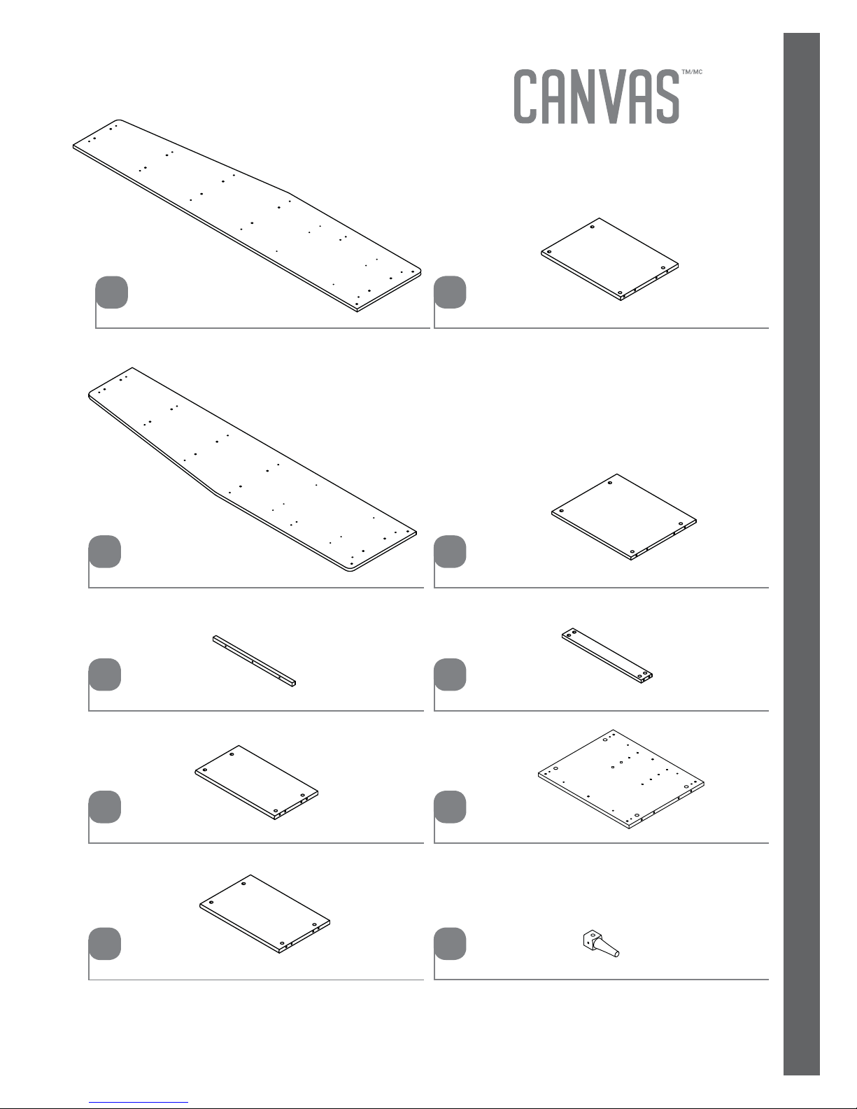
PARTS LIST
A
Right End - 1
Left End
- 1
B
Top Molding - 1
C
Top - 1
D
Small Shelf - 1
E
Shelf - 1
F
Large Shelf - 1
G
Brace - 1
H
Right Front/Left Rear Foot - 2
J
Bottom - 1
I

4
MODEL NO. 068-7826-4
K
Left Front/Right Rear Foot - 2
Bottom Brace - 2
L
Left Drawer Side - 2
M
Drawer Back - 2
N
Right Drawer Side - 2
O
Drawer Bottom - 2
P
Drawer Brace - 2
Q
Back - 1
S
PARTS LIST
Drawer Front - 2
R

5
PARTS LIST
Large Hidden Cam- 36
3
Small Hidden Cam - 12
4
Long Wood Dowel - 30
7
Short Wood Dowel - 4
8
Cover Card - 1
9
Knob - 2
10
Long File Glide - 2
11
Short File Glide - 4
12
Angled Head Cam Screw - 36
5
Angled head
Straight Head Cam Screw - 12
6
Straight head
Extension Rail - 4
1
Extension Slide - 4
2
Extension Set
shown separated

6
MODEL NO. 068-7826-4
Front File Glide - 2
13
Black 2-9/16" Bolt - 8
18
Black 1-1/8" Flat Head Screw - 3
20
Black 1-1/2" Flat Head Screw - 12
19
Black 7/8" Machine Screw - 2
21
Black 1/2" Pan Head Screw - 32
22
Furniture Tipping Restraint Kit - 1
99
Flat Washer - 8
15
File Hanger - 4
14
Ballast - 2
16
Nail - 50
17
PARTS LIST

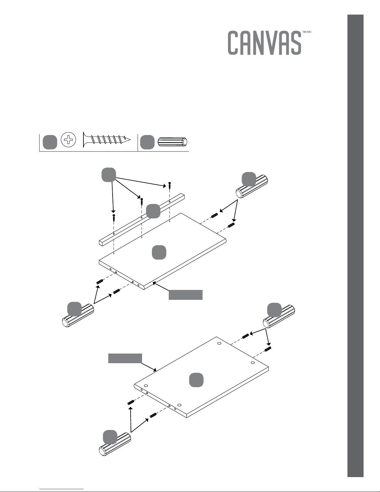
7
ASSEMBLY
D
E
Step 1
Requires C, D, E, 7, 20
Fasten the TOP MOLDING (C) to the TOP (D). Use three BLACK 1-1/8" FLAT HEAD
SCREWS (20).
Insert eight LONG WOOD DOWELS (7) into the exact holes shown in the short edges of
the TOP (D) and SMALL SHELF (E).
Rounded edge
Rounded edge
7
7
7
7
C
7
20
ASSEMBLY
20

8
ASSEMBLY
MODEL NO. 068-7826-4
G
F
Step 2
Requires F, G, 7
Insert eight LONG WOOD DOWELS (7) into the into the exact holes shown in the short
edges of the SHELVES (F and G).
7
7
7
7
Rounded edge
Rounded edge
7

9
ASSEMBLY
Step 3
Requires I, 5, 7
Turn eight ANGLED CAM SCREWS (5) into the small holes in the BOTTOM (I).
Insert four LONG WOOD DOWELS (7) into the edges of the BOTTOM (I).
I
Angled head
7
7
Angled head
5 7
Finished
Edge
5

10
ASSEMBLY
MODEL NO. 086-7826-4
Step 4
Requires J, K, L, 3, 5, 7
Turn two ANGLED HEAD CAM SCREWS (5) into the FEET (J and K).
Insert two LONG WOOD DOWELS (7) into the FEET (J and K) and one into the long
edge of the BOTTOM BRACE (L).
Insert two LARGE HIDDEN CAMS (3) into the holes in the BOTTOM BRACE (L) as shown.
Fasten the FEET (J and K) to the BOTTOM BRACE (L). Tighten two LARGE HIDDEN CAMS.
Repeat this step for the other FEET (J and K) and BOTTOM BRACE (L).
321
The arrow must
point toward the
edge of the board.
3
Angled head
5 73
7
7
7
5
5
3
J
K
L
Angled head

11
ASSEMBLY
Step 5
Requires J, K, L, 3, 7
Insert four LONG WOOD DOWELS (7) into the BOTTOM (I).
Insert eight LARGE HIDDEN CAMS (3) into the holes in the BOTTOM BRACE (L) and
FEET (J and K) as shown.
Fasten the FEET (J and K) and BOTTOM BRACES (L) to the BOTTOM (I). Tighten eight
LARGE HIDDEN CAMS.
321
The arrow must
point toward the
edge of the board.
3
73
7
7
7
7
3
3
3
I
J
J
K
K
L
L
Angled head

12
ASSEMBLY
MODEL NO. 068-7826-4
Step 6
Requires I, 15, 16, 18
Flip the BOTTOM (I) over onto the FEET.
Fasten a BALLAST (16) to the BOTTOM (I) exactly as shown. Use four BLACK 2-9/16"
BOLTS (18) and four FLAT WASHERS (15).
18
1615
I
18
18
15
15
16

13
ASSEMBLY
Step 7
Requires B, 1, 5, 22
Separate the EXTENSION SLIDES (2) from the EXTENSION RAILS (1) as shown in the
diagram. Be prepared; the parts are greasy.
Fasten two EXTENSION RAILS (1) to the LEFT END (B). Use six BLACK 1/2" PAN HEAD
SCREWS (22).
NOTE: For each EXTENSION RAIL, turn a SCREW into the holes shown in the diagram.
Then, slide the inner cartridge of the EXTENSION RAIL in to fi nd the other two holes that
line up with the holes in the LEFT END. Turn the SCREWS into those holes.
NOTE: The EXTENSION SLIDES will be used later for the DRAWERS.
Turn twelve ANGLED HEAD CAM SCREWS (5) into the LEFT END (B).
Use these holes.
Push the black lever down and
pull the SLIDE from the RAIL.
Angled edge
Angled head
Angled head
51
22
5
1
1
1
2
22
22
B
Open end
Open end

14
ASSEMBLY
MODEL NO. 068-7826-4
Step 8
Requires A, 1, 5, 22
Fasten two EXTENSION RAILS (1) to the RIGHT END (A). Use six BLACK 1/2" PAN HEAD
SCREWS (22).
NOTE: For each EXTENSION RAIL, turn a SCREW into the holes shown in the diagram.
Then, slide the inner cartridge of the EXTENSION RAIL in to fi nd the other two holes that
line up with the holes in the RIGHT END. Turn the SCREWS into those holes.
Turn twelve ANGLED HEAD CAM SCREWS (5) into the RIGHT END (A).
Angled edge
Angled head
Angled head
51
22
5
22
22
A
1
1
Open end
Open end

15
ASSEMBLY
Step 9
Requires B, D, E, F, G, H, I, 3, 8
Insert two SHORT WOOD DOWELS (8) into the FEET (J and K).
Insert twelve LARGE HIDDEN CAMS (3) into the TOP (D), SHELVES (E , F and G),
BRACE (H) and BOTTOM (I).
Fasten the LEFT END (B) to the TOP (D), SHELVES (E , F and G), BRACE (H) and
BOTTOM (I). Tighten twelve LARGE HIDDEN CAMS.
NOTE: Be sure the WOOD DOWELS in the TOP, SHELVES, BOTTOM and FEET insert into
the LEFT END.
K
B
321
The arrow must
point toward the
edge of the board.
3
Angled edge
83
J
3
3
3
8
8
Surface with holes
Surface with holes
D
E
F
G
H
I
3

16
ASSEMBLY
MODEL NO. 068-7826-4
Step 10
Requires A, 3, 8
Insert two SHORT WOOD DOWELS (8) into the FEET (J and K).
Insert twelve LARGE HIDDEN CAMS (3) into the TOP (D), SHELVES (E , F and G),
BRACE (H) and BOTTOM (I).
Fasten the RIGHT END (A) to the TOP (D),
SHELVES (E , F and G), BRACE (H)
, BRACE (H)
and BOTTOM (I). Tighten twelve LARGE HIDDEN CAMS.
NOTE: Be sure the WOOD DOWELS in the TOP, SHELVES, BOTTOM and FEET insert into
the RIGHT END.
321
The arrow must
point toward the
edge of the board.
3
83
J
A
3
3
K
3
8
8
D
E
F
G
H
I
Angled edge
3

17
ASSEMBLY
Step 11
Requires S, 15, 16, 17, 18
Carefully turn your unit over onto its front edges. Unfold the BACK (S) and lay it over
your unit.
Place packing material under the angled ends to stabilize the unit.
Make equal margins along all four edges of the BACK (S). Push on opposite corners of
your unit if needed to make it "square".
Fasten the BACK (S) to your unit using fi fty NAILS (17).
NOTE: Perforations have been provided for access through the BACK. Carefully cut out
the holes needed.
Fasten the remaining BALLAST (16) to the BOTTOM (I) exactly as shown. Use four
BLACK 2-9/16" BOLTS (18) and four FLAT WASHERS (15).
18
18
1716
16
15
15
Unfi nished surface
Do not use this
hole in this step.
S
These holes must line up
over the SHELVES.
These perforations
must be here.
Place packing
material here to
stabilize the unit.
17
I

18
ASSEMBLY
MODEL NO. 068-7826-4
Step 12
Requires M, O, 2, 22
Fasten two EXTENSION SLIDES (2) to the DRAWER SIDES (M and O). Use six BLACK
1/2" PAN HEAD SCREWS (22) through holes 3, 6, and 9 from the open end.
NOTE: Complete steps 11-17 for assembly of one drawer. Then, repeat these steps to
complete the assembly of the other drawer.
O
M
Open end
Open end
Groove is down.
2
2
22
2
Use these holes.
Open end
22
22
Groove is down.

19
ASSEMBLY
Step 13
Requires R, 6, 10, 13, 21, 22
Turn six STRAIGHT HEAD CAM SCREWS (6) into the DRAWER FRONT (R).
Fasten a KNOB (10) to the DRAWER FRONT (R). Use a BLACK 7/8" MACHINE SCREW (21)
.
Fasten a FRONT FILE GLIDE (13) to the DRAWER FRONT (R) as shown below. Use four
BLACK 1/2" PAN HEAD SCREWS (22).
R
R
13 6
Straight head
22
13
6
The fl ange is facing
toward this edge of
the DRAWER FRONT.
22
2110
10
21

20
ASSEMBLY
MODEL NO. 068-7826-4
M
O
4
4
4
Step 14
Requires M, O, Q, R, 4
Insert six SMALL HIDDEN CAMS (4) into one DRAWER SIDE (M and O) and a DRAWER
BRACE (Q).
Fasten the DRAWER SIDES (M and O) and DRAWER BRACE (Q) to the DRAWER FRONT (R).
Tighten six SMALL HIDDEN CAMS.
321
The arrow must
point toward the
edge of the board.
4
4
Q
R
Groove

21
ASSEMBLY
N
P
Step 15
Requires P, N, 19
Slide a DRAWER BOTTOM (P) into the grooves in the DRAWER SIDES (M and O) and
DRAWER FRONT (R).
Fasten a DRAWER BACK (N) to the DRAWER SIDES (M and O) and DRAWER BRACE (Q).
Use six BLACK 1-1/2" FLAT HEAD SCREWS (19).
19
Unfi nished surface
Unfi nished surface
Be sure the DRAWER
BOTTOM inserts into the
DRAWER BACK groove.
19
19
M
M
O
O
Q
R

22
ASSEMBLY
MODEL NO. 068-7826-4
Step 16
Requires 11, 12
Push two SHORT FILE GLIDES (12) onto the DRAWER SIDES (M and O) as shown.
Push a LONG FILE GLIDE (11) onto the DRAWER BACK (N) as shown.
N
M
O
12
12
11
1211

23
ASSEMBLY
Step 17
Requires 14
Push two FILE HANGERS (14) onto the FRONT FILE GLIDE (13) and LONG FILE GLIDE (11)
.
Repeat steps 11-17.
14
14
11
13
14

24
ASSEMBLY
MODEL NO. 068-7826-4
Step 18
Requires 9
Before inserting the drawers, move your unit close to its fi nal position.
To insert the drawers into your unit, line up the EXTENSION SLIDES on the drawers with
the EXTENSION RAILS on the unit and push the drawers into the unit until they are fully
inserted. The drawers will push in hard until they are all the way in, then they will slide in
and out easier.
Peel a CAM COVER from CAM COVER CARD (9) and stick it onto each HIDDEN CAM.
9
35 lbs.
35 lbs.
25 lbs.
25 lbs.
15 lbs.
No load

25
ASSEMBLY
Step 19
Requires 99
We recommend using the FURNITURE TIPPING RESTRAINT KIT (99) for added stability.
Fasten a bracket to the back edge of the TOP (D) using the 5/8" screws as shown.
NOTE: You will use the hole in the BACK that were not used in Step 10.
Place your unit in its fi nal location against a wall.
Follow the instructions included in the KIT to fasten your unit to the wall.
This completes assembly. Clean with your favorite furniture polish or a damp cloth.
Wipe dry.
99
Use the 5/8" screw through the
small hole in a bracket and into
the back edge of the TOP (D).
Small hole
99
D

26
WARRANTY
This CANVAS™ product carries a one (1) year warranty against defects in workmanship and
materials. Trileaf Distribution agrees to replace the defective product free of charge within the
stated warranty period, when returned by the original purchaser with proof of purchase. This
product is not guaranteed against wear or breakage due to misuse and/or abuse.
Made in China
Imported by
Trileaf Distribution Trifeuil Toronto, Canada M4S 2B8
1-YEAR LIMITED WARRANTY
MODEL NO. 068-7826-4

CONSIGNES D’ASSEMBLAGE
Numéro sans frais : 1 888 670-6684
IMPORTANT : Veuillez lire attentivement ce guide avant de procéder à l’assemblage de ce
produit. Conservez ce guide aux fi ns de consultation ultérieure.
CLASSEUR ANDERSON
N° DE MODÈLE : 068-7826-4

28
CONSIGNES DE SÉCURITÉ IMPORTANTES TABLE DES MATIÈRES
Consignes de sécurité importantes 2
Liste des pièces 3-6
Assemblage 7-25
Garantie 26
N° DE MODÈLE : 068-7826-4
Avertissement! Pour réduire le risque de blessures graves, lisez les
consignes de sécurité suivantes avant d’assembler et d’utiliser la table.
• Ce produit est uniquement destiné à un usage domestique et doit être utilisé à l’intérieur.
• Le produit doit être placé sur une surface plane et horizontale.
• Au besoin, demandez à d’autres personnes de vous aider à assembler ou déplacer le produit.
• Ne poussez pas le meuble, particulièrement sur un plancher en tapis. Demandez à quelqu’un de vous aider
à soulever les articles lourds et à les mettre en place.
• Vérifi ez périodiquement que les vis sont bien serrées. Au besoin, resserrez-les.
Pièces requises pour l’assemblage
Marteau
Tournevis à tête en forme d'étoile no 2
Taille réelle de la pointe illustrée
29
LISTE DES PIÈCES
A
Côté droit - 1
Côté gauche - 1
B
Moulure supérieure - 1
C
Dessus - 1
D
Petite tablette - 1
E
Tablette - 1
F
Grande tablette - 1
G
Entretoise - 1
H
Pied avant droit/arrière gauche - 2
J
Fond - 1
I

3030
N° DE MODÈLE : 068-7826-4
LISTE DES PIÈCES
K
Pied avant gauche/arrière droit - 2
Entretoise inférieure - 2
L
Côté gauche du tiroir - 2
M
Arrière du tiroir - 2
N
Côté droit du tiroir - 2
O
Fond du tiroir - 2
P
Entretoise du tiroir - 2
Q
Arrière - 1
S
Devant du tiroir - 2
R

31
LISTE DES PIÈCES
Grande came dissimulée - 36
3
Petite came dissimulée - 12
4
Long goujon en bois - 30
7
Goujon court en bois - 4
8
Carte de cache-cames - 1
9
Bouton - 2
10
Longue tige de glissement pour pochettes - 2
11
Courte tige de glissement pour pochettes - 4
12
Vis de came à tête à angle - 36
5
Tête à angle
Vis de came avec tête droite - 12
6
Tête droite
Rail d’allongement - 4
1
Coulisse d’allongement - 4
2
Ensemble d’allongement illustré séparément

3232
N° DE MODÈLE : 068-7826-4
LISTE DES PIÈCES
Tige de glissement avant pour pochettes - 2
13
Boulon noir de 2 9/16 po - 8
18
Vis à tête plate noire de 1 1/8 po - 3
20
Vis à tête plate noire de 1 ½ po - 12
19
Vis à métal noire de 7/8 po - 2
21
Vis noire à tête cylindrique bombée de 1/2 po - 32
22
Trousse d’antibasculement pour meuble - 1
99
Rondelle plate - 8
15
Support à dossiers - 4
14
Ballast - 2
16
Clou - 50
17
33
ASSEMBLAGE
Étape 1
Pièces requises : C, D, E, 7, 20
Visser la MOULURE SUPÉRIEURE (C) sur le DESSUS (D). Utiliser trois VIS À TÊTE PLATE
NOIRE DE 1 1/8 PO (20).
Insérer huit LONGS GOUJONS EN BOIS (7) dans les trous précis illustrés dans les bords
courts du DESSUS (D) et dans la PETITE TABLETTE (E).
D
E
Bord arrondi
Bord arrondi
7
7
7
7
C
7
20
20

34
ASSEMBLAGE
N° DE MODÈLE : 068-7826-4
Étape 2
Pièces requises : F, G, 7
Insérer huit LONGS GOUJONS EN BOIS (7) dans les trous précis illustrés dans les bords
courts des TABLETTES (F et G).
G
F
7
7
7
7
Bord arrondi
Bord arrondi
7

35
Étape 3
Pièces requises : I, 5, 7
Visser huit VIS DE CAME À ANGLE (5) dans les petits trous du FOND (I). Insérer quatre
LONGS GOUJONS EN BOIS (7) dans le FOND (I).
I
Tête à angle
7
7
Tête à angle
5 7
Bord avec
fi n i t i o n
5
ASSEMBLAGE

36
ASSEMBLAGE
N° DE MODÈLE : 068-7826-4
Étape 4
Pièces requises : J, K, L, 3, 5, 7
Visser deux VIS DE CAME À TÊTE À ANGLE (5) dans les PIEDS (J et K).
Insérer deux LONGS GOUJONS EN BOIS (7) dans les PIEDS (J et K) et un dans le bord
long de l'ENTRETOISE INFÉRIEURE (L).
Insérer deux GRANDES CAMES DISSIMULÉES (3) dans les trous de l'ENTRETOISE
INFÉRIEURE (L) comme illustré.
Fixer les PIEDS (J et K) à l’ENTRETOISE INFÉRIEURE (L). Serrer deux GRANDES
CAMES DISSIMULÉES.
Répéter cette étape pour les autres PIEDS (J et K) et l’ENTRETOISE INFÉRIEURE (L).
321
La fl èche doit
pointer vers le
bord du panneau.
3
Tête à angle
5 73
7
7
7
5
5
3
J
K
L
Tête à angle

37
ASSEMBLAGE
Étape 5
Pièces requises : J, K, L, 3, 7
Insérer quatre LONGS GOUJONS EN BOIS (7) dans le FOND (I).
Insérer huit GRANDES CAMES DISSIMULÉES (3) dans les trous de l'ENTRETOISE
INFÉRIEURE (L) et des PIEDS (J et K) comme illustré.
Fixer les PIEDS (J et K) et l’ENTRETOISE INFÉRIEURE (L) sur le FOND (I). Serrer huit
GRANDES CAMES DISSIMULÉES.
321
La fl èche doit
pointer vers le
bord du panneau.
3
73
7
7
7
7
3
3
3
I
J
J
K
K
L
L
Tête à angle

38
ASSEMBLAGE
N° DE MODÈLE : 068-7826-4
Étape 6
Pièces requises : I, 15, 16, 18
Retourner le FOND (I) pour le mettre sur ses pattes.
Attacher un BALLAST (16) sur le FOND (I) exactement comme illustré. Utiliser quatre
BOULONS NOIRS de 2 9/16 po (18) et quatre RONDELLES PLATES (15).
18
1615
I
18
18
15
15
16

39
ASSEMBLAGE
Étape 7
Pièces requises : B, 1, 5, 22
Séparer les COULISSES D’ALLONGEMENT (2) des RAILS D’ALLONGEMENT (1) comme
illustré dans le diagramme. Prendre garde; les pièces sont graisseuses.
Fixer deux RAILS D’ALLONGEMENT (1) au CÔTÉ GAUCHE (B). Utiliser six VIS NOIRES À
TÊTE CYLINDRIQUE BOMBÉE DE ½ PO (22).
REMARQUE : Pour chaque RAIL D'ALLONGEMENT, visser une VIS dans les trous illustrés
sur le diagramme. Ensuite, faire glisser la cartouche intérieure du RAIL D’ALLONGEMENT
vers l’intérieur pour trouver les deux autres trous alignés avec les trous dans le CÔTÉ
GAUCHE. Visser les VIS dans ces trous.
REMARQUE : Les COULISSES D’ALLONGEMENT seront utilisées plus tard pour les
TIROIRS. Visser douze VIS DE CAME À TÊTE À ANGLE (5) dans le CÔTÉ GAUCHE (B).
Utiliser ces trous.
Pousser le levier noir vers le bas et tirer sur
la COULISSE afi n de la sortir de la RAIL.
Bord à angle
Tête à angle
Tête à angle
51
22
5
1
1
1
2
22
22
B
Extrémité ouverte
Extrémité ouverte

40
ASSEMBLAGE
N° DE MODÈLE : 068-7826-4
Étape 8
Pièces requises : A, 1, 5, 22
Fixer deux RAILS D’ALLONGEMENT (1) au CÔTÉ DROIT (A). Utiliser six VIS NOIRES À
TÊTE CYLINDRIQUE BOMBÉE DE ½ PO (22).
REMARQUE : Pour chaque RAIL D'ALLONGEMENT, visser une VIS dans les trous illustrés
sur le diagramme. Ensuite, faire glisser la cartouche intérieure du RAIL D’ALLONGEMENT
vers l’intérieur pour trouver les deux autres trous alignés avec les trous dans le CÔTÉ
DROIT. Visser les VIS dans ces trous.
Visser douze VIS DE CAME À TÊTE À ANGLE (5) dans le CÔTÉ DROIT (A).
Bord à angle
Tête à angle
Tête à angle
51
22
5
22
22
A
1
1
Extrémité ouverte
Extrémité ouverte

41
ASSEMBLAGE
Étape 9
Pièces requises : B, D, E, F, G, H, I, 3, 8
Insérer deux GOUJONS COURTS EN BOIS (8) dans les PIEDS (J et K).
Insérer douze GRANDES CAMES DISSIMULÉES (3) dans le DESSUS (D), les TABLETTES (E, F
et G), l'ENTRETOISE (H) et le FOND (I).
Fixer le CÔTÉ GAUCHE (B) au DESSUS (D), aux TABLETTES (E, F et G), à l’ENTRETOISE (H)
et au FOND (I). Serrer douze GRANDES CAMES DISSIMULÉES.
REMARQUE : Veiller à insérer les GOUJONS EN BOIS du le DESSUS, des TABLETTES, du
FOND et des PIEDS dans le CÔTÉ GAUCHE.
K
B
321
La fl èche doit
pointer vers le
bord du panneau.
3
Bord à angle
83
J
3
3
3
8
8
Surface trouée
Surface trouée
D
E
F
G
H
I
3

42
ASSEMBLAGE
N° DE MODÈLE : 068-7826-4
Étape 10
Pièces requises : A, 3, 8
Insérer deux GOUJONS COURTS EN BOIS (8) dans les PIEDS (J et K).
Insérer douze GRANDES CAMES DISSIMULÉES (3) dans le DESSUS (D), les TABLETTES (E, F
et G), l'ENTRETOISE (H) et le FOND (I).
Fixer le CÔTÉ DROIT (A) au DESSUS (D), aux TABLETTES (E, F et G), à l’ENTRETOISE (H)
et au FOND (I). Serrer douze GRANDES CAMES DISSIMULÉES.
REMARQUE : Veiller à insérer les GOUJONS EN BOIS du le DESSUS, des TABLETTES, du
FOND et des PIEDS dans le CÔTÉ DROIT.
321
La fl èche doit
pointer vers le
bord du panneau.
3
83
J
A
3
3
K
3
8
8
D
E
F
G
H
I
Bord à angle
3

43
ASSEMBLAGE
Étape 11
Pièces requises : S, 15, 16, 17, 18
Retourner délicatement l’unité sur ses bords avant. Déplier le(s) FOND(S) et les déposer
sur l’unité.
Placer du matériau d’emballage sous les bords à angle pour stabiliser l’unité.
Égaliser les marges entre les quatre bords du(des) FOND(S). Pousser les coins opposés
de l’unité au besoin pour la rendre carrée.
Fixer le(s) FOND(S) sur l'unité avec cinquante CLOUS (17).
REMARQUE : Des perforations sont fournies pour donner l'accès par le FOND. Découper
délicatement les trous nécessaires.
Fixer l'autre BALLAST (16) sur le FOND (I), exactement comme illustré. Utiliser quatre
BOULONS NOIRS DE 2 9/16 PO (18) et quatre RONDELLES PLATES (15).
18
171615
18
16
15
Surface sans fi nition
Ne pas utiliser ce
trou à cette étape.
S
Ces trous doivent être
alignés avec les TABLETTES.
Ces perforations
doivent être ici.
Placer du matériau
d’emballage ici pour
stabiliser l’unité.
17
I

44
ASSEMBLAGE
N° DE MODÈLE : 068-7826-4
Étape 12
Pièces requises : M, O, 2, 22
Fixer deux COULISSES D’ALLONGEMENT (2) aux CÔTÉS DE TIROIR (M et O). Utiliser
six VIS NOIRES À TÊTE CYLINDRIQUE BOMBÉE DE ½ PO (22) dans les trous 3, 6 et 9 à
partir de l'extrémité ouverte.
REMARQUE : E ectuer les étapes 11 à 17 pour l’assemblage d’un tiroir. Répéter ensuite
ces étapes pour e ectuer l’assemblage de l’autre tiroir.
O
M
Extrémité ouverte
Extrémité ouverte
Rainure vers le bas.
2
2
22
2
Utiliser ces trous.
Extrémité ouverte
22
22
Rainure vers le bas.

45
ASSEMBLAGE
Étape 13
Pièces requises : R, 6, 10, 13, 21, 22
Tourner six VIS DE CAME À TÊTE DROITE (6) dans le DEVANT DE TIROIR (R).
Fixer un BOUTON (10) au DEVANT DU TIROIR (R). Utiliser une VIS NOIRE À MÉTAL DE 7/8 PO (21).
Fixer une TIGE DE GLISSEMENT AVANT (13) sur un DEVANT DE TIROIR (R), comme
illustré. Utiliser quatre VIS NOIRES À TÊTE CYLINDRIQUE BOMBÉE DE ½ PO (22).
R
R
13 6
Tête droite
22
13
6
L’embase fait face à
ce bord du DEVANT
DU TIROIR.
22
2110
10
21

46
ASSEMBLAGE
N° DE MODÈLE : 068-7826-4
Étape 14
Pièces requises : M, O, Q, R, 4
Insérer six PETITES CAMES DISSIMULÉES (4) dans un CÔTÉ DE TIROIR (M et O) et une
ENTRETOISE DE TIROIR (Q).
Fixer les CÔTÉS DE TIROIR (M et O) et l’ENTRETOISE DE TIROIR (Q) au DEVANT DU
TIROIR (R). Visser six PETITES CAMES DISSIMULÉES.
M
O
4
4
4
321
La fl èche doit
pointer vers le
bord du panneau.
4
4
Q
R
Rainure

47
ASSEMBLAGE
Étape 15
Pièces requises : P, N, 19
Glisser un FOND DE TIROIR (P) dans les rainures des CÔTÉS DE TIROIR (M et O) et du
DEVANT DE TIROIR (R).
Fixer un FOND DE TIROIR (N) aux CÔTÉS DE TIROIR (M et O) et à l’ENTRETOISE DE
TIROIR (Q). Utiliser six VIS NOIRES À TÊTE PLATE DE 1 ½ PO (19).
N
P
19
Surface sans fi nition
Surface sans fi nition
Insérer le FOND DE
TIROIR dans la rainure
de l’ARRIÈRE DU TIROIR.
19
19
M
M
O
O
Q
R

48
ASSEMBLAGE
N° DE MODÈLE : 068-7826-4
Étape 16
Pièces requises : 11, 12
Enfoncer deux COURTES TIGES DE GLISSEMENT POUR POCHETTES (12) sur les CÔTÉS
DE TIROIR (M et O), comme illustré.
Enfoncer une LONGUE TIGE DE GLISSEMENT POUR POCHETTES (11) sur l’ARRIÈRE DU
TIROIR (N), comme illustré.
N
M
O
12
12
11
1211

49
ASSEMBLAGE
Étape 17
Pièces requises : 14
Enfoncer deux SUPPORTS À DOSSIERS (14) sur la TIGE DE GLISSEMENT AVANT POUR
POCHETTES (13) et la LONGUE TIGE DE GLISSEMENT POUR POCHETTES (11).
Répéter les étapes 11 à 17.
14
14
11
13
14

50
ASSEMBLAGE
N° DE MODÈLE : 068-7826-4
Étape 18
Pièces requises : 9
Avant d’insérer les tiroirs, déplacer l’unité près de son emplacement fi nal.
Pour insérer les tiroirs dans l'unité, aligner les COULISSES D’ALLONGEMENT des tiroirs
avec les RAILS D’ALLONGEMENT de l’unité et pousser les tiroirs dans l’unité jusqu’à
ce qu’ils soient entièrement insérés. Il est di cile de pousser les tiroirs jusqu’à ce qu'ils
soient complètement entrés; ils s'ouvriront et se fermeront ensuite plus facilement.
Décoller les CACHE-CAMES de la CARTE DE CACHE-CAMES (9) et les coller sur chaque
CAME DISSIMULÉE.
9
15,8 kg (35 lb)
11,3 kg (25 lb)
6,8 kg (15 lb)
Aucune charge
11,3 kg (25 lb)
15,8 kg (35 lb)

51
ASSEMBLAGE
Étape 19
Pièces requises : 99
Il est recommandé d’utiliser la TROUSSE ANTIBASCULEMENT POUR MEUBLE (99) pour
une stabilité accrue.
Fixer une ferrure au bord arrière du DESSUS (D) à l’aide des vis de 5/8 po, comme illustré.
REMARQUE : Utiliser le trou dans l’ARRIÈRE qui n’a pas été utilisé à l’étape 10.
Placer l’unité à son emplacement fi nal, appuyée sur un mur.
Suivre les instructions incluses dans la TROUSSE pour fi xer l’unité au mur.
L’assemblage est terminé. Nettoyer à l’aide d’une cire pour meubles ou d’un linge
humide. Essuyer.
99
Petit trou
99
D
Utiliser une vis de 5/8 po dans le
petit trou d’une ferrure et dans le
bord arrière du DESSUS (D).

52
GARANTIE
Cet article CANVAS comporte une garantie de un (1) an contre les défauts de fabrication et de
matériau(x). Distribution Trifeuil consent à remplacer l’article défectueux sans frais lorsqu’il est
retourné, accompagné de la preuve d’achat, par l’acquéreur initial au cours de la période de
garantie convenue. Exclusion : usure ou bris causés par un usage abusif ou inapproprié.
Fabriqué en Chine
Importé par
Trileaf Distribution Trifeuil Toronto, Canada M4S 2B8
GARANTIE LIMITÉE DE 1 AN
N° DE MODÈLE : 068-7826-4
 Loading...