

Page 1

Follow Spotlight
575, 700, 1200 Watt Metal Halide
1000, 2000 Watt Tungsten-Halogen
Rev. Feb 20 12
CantoUSA
1092 West Atlanta Street
Marietta, Georgia 30060 USA
Tel 888/252-5912 • Fax 866 /260-3549
www.cantousa.com
Page 2

Carefully read user’s instructions before using this lighting unit.
The instructions given here insure safe and correct usage of this product.
User’s failure to comply with the installation, operating, maintenance
and safety procedures outlined in this manual, as well as those generally
applicable to this lighting equipment, may cause the spotlight to perform
in an unsatisfactory manner. Strong Entertainment Lighting accepts no
liability for direct, indirect, incidental, special, or consequential damages
resulting from the customer’s failure to follow the installation, operating,
maintenance and safety procedures in this manual or those generally
applicable to lighting equipment.
The above limitation extends to damages for personal injury, property
damage, loss of operations, loss of profits, loss of product or loss of
time, whether incurred by the customer, the customer’s employees, or a
third party. Apart from the instructions given on this manual, the user
must comply with all relevant safety and health standards of the
appropriate UL Directives, and all local codes.
Page 3

PREFACE
THE CANTO FOLLOW SPOTLIGHT is manufactured in Italy by Luci della Ribalta and
imported and marketed in the United States by Strong Entertainment Lighting. The metal halide Canto
models are available in 575, 700, and 1200 watt models, and require use of a separate power supply unit of
the correct wattage. Each power supply operates from a 120 volt, 15 ampere AC line. Tungsten-halogen
models, using either a 1000 watt FEL or 2000 watt GAE bulb, operate from a 120 volt AC line (20 ampere
service required for 2000 watt model). Each unit is supplied complete with a lamphouse, optical system,
yoke, and 1-1/8" (28mm) spigot/truss pin. The metal halide power supply is included as required. A tripod
floor stand and a five-color boomerang are available as optional accessories.
BULBS and color gels are available from theatrical supply distributors. Rated hours or
warranted life of the bulb will vary by type and wattage, and should be noted at installation. It is
generally recommended to keep a spare replacement bulb on hand. Bulbs from manufacturers other
than those listed on Page 5 must be certified by their manufacturer as being 100% interchangeable.
IMPORTANT SAFETY PRECAUTIONS
• This product operates at high temperatures. Avoid any direct contact with its metallic parts.
• WARNING: high voltage ignition cycle.
• UV Rays: the lamps used on the metal halide models (Canto 575, 700 and 1200) emit UV rays. Protect
your eyes and never look directly at the source of light without appropriate eye protection.
• This product requires forced-air ventilation. Make sure you do not cover the fan or obstruct the air
flow at any time.
• Make sure the fan is working correctly. Should you detect even the slightest malfunctioning, switch
the spotlight off and carry out the necessary servicing. Replace the fan if necessary.
• This product is designed for indoor use only. For details on maximum ambient temperature, minimum
distance from flammable objects, and tilt angle, please refer to the data plate.
• Replace the bulb, the mirror and the lenses if damaged or deformed by heat. Make sure the lamp is
cold before attempting to remove it. To correctly install the lamp, please refer to the lamp manufacturer’s
instructions included in the lamp box and to the relevant section in this manual.
• Repair and replacement of any component of this product must be carried out exclusively by trained
personnel in compliance with the relevant safety and health standards, and using only original factory
components.
• Replacement of any part of the wiring system must be carried out exclusively by trained personnel in
compliance with the original wiring diagram and using components identical to or compatible with
those originally fitted.
• Installation of this product must be performed exclusively by trained personnel in compliance with the
codes and safety standards in force in the region where the product is used.
1
Page 4
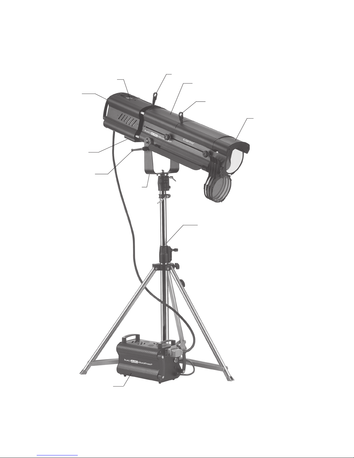
CANTO SPOTLIGHT
Cooling Fan
Lamphouse
Lampholder
Tilt Friction Brake
Control Lever
Iris Control Lever
Optical System
Fade-Out/Douser
Control Lever
Color Boomerang
(optional)
Yoke
Tripod Floor Stand
(optional)
Power Supply Unit
(Metal Halide models only)
2
Page 5

1. RECEIVING
Upon opening the packaging, locate and identify the following:
Spotlight
a. Followspot
b. Iris (blackout iris diaphragm if specifically ordered; not available for Canto 2000)
c. Truss pin/spigot (1.11" diameter) with 12mm self-locking nut and plain washer
d. Instruction manual
Power Supply (only for Canto 575, Canto 700 and Canto 1200 metal halide)
a. 110/120 Volt, 50/60 Hz. ballast
2. MOUNTING THE SPIGOT/TRUSS PIN
a. Make sure the tripod you are going to use features a 1.1" (28mm) diameter top aperture.
b. Remove the nut and the washer from the spigot.
c. Insert the spigot in the central hole of the yoke of the followspot from beneath the yoke.
d. Add the plain washer and the self-locking nut and tighten the nut with a suitable wrench.
e. Mount the followspot on the tripod or truss. Make sure the structure to which you are fixing the
spotlight to is rated for the product load:
Canto 575, 700, & 1200: 37 lb. (16.4 kg)
Canto 1000, 2000: 34 lb. (15.1 kg)
3. MOUNTING THE COLOR BOOMERANG (optional accessory, Part No. 20105006)
a. Remove the color frame from the front of the followspot optical system.
b. At the front of the followspot, remove the (2) cross-head self-tapping screws from one of the two
front color runners. Reposition the two screws in their original holes and tighten them.
c. Repeat with the second color runner.
d. Take the (3) supplied 4mm socket head screws and position each one of them, only halfway through,
in each one of the 4mm-threaded Avdel brass inserts on the front plate of the followspot optical
system housing.
e. Mount color filters on the boomerang arms. See relevant instructions supplied with the boomerang.
f. Position the boomerang unit on the front plate of the followspot, making sure that the color levers are
positioned on the right-hand side of the followspot (when viewed from behind). Hang it using the
keyhole openings in the boomerang frame onto the previously positioned socket head screws.
g. Release the color filters of the boomerang to allow access to the (3) screws and tighten them.
h. Ensure the boomerang unit is secure, and all three screws are tight.
NOTE: Do not discard the removed color runners and color frame, as they will be needed if the follow
spot is returned to its original, standard configuration.
3
Page 6

4. MOUNTING THE IRIS
The iris supplied with the followspot uses 20 leaves to size the beam from a maximum aperture of 2.68"
(68mm) to a minimum of 0.20" (5mm). A blackout iris is available on special order. The iris is preassembled
in Strong Entertainment Lighting units, and replacements are installed as follows:
a. Using a phillips screwdriver, remove the two cross-head screws from the sides of the iris bracket
located in the gap between the lamphouse and optical system. Lift the old iris out of the bracket.
b. Slide the new iris down into the bracket, flat surface toward the lamphouse.
c. Replace the screws.
Important Notice: while the lamp is on. . .
Do not leave the iris closed for longer than:
• 10 minutes on Canto 575, Canto 700, Canto 1000 and Canto 1200
• 2 minutes on Canto 2000
Use the douser (front lever) to cut off the light should you require to have the lamp “on” with no beam
projecting to the stage.
FAILURE TO COMPLY WITH ABOVE NOTICE MAY CAUSE THE IRIS AND THE FOLLOWSPOT
TO SUFFER MAJOR HEAT DAMAGES AND WILL INVALIDATE THE PRODUCT WARRANTY
5. SHUTTER BLADES
Shutter blades are not supplied with the unit but are available as separate accessory. They are sold as
single items and relevant part number is 80852039.
6. ADJUSTING THE YOKE
This followspot is provided with a yoke balancing adjustment. The balancing point is factory-set for
standard usage of the product; however, should you need to adjust the balancing, proceed as follows:
a. The followspot must be tripod mounted.
b. Using a phillips screwdriver, loosen the (2) 5mm screws on each side of the yoke.
c. Gently slide the followspot backwards or forwards to the required position.
d. Make sure the yoke is correctly aligned horizontally.
e. Tighten the (4) 5mm screws.
7. WIRING
Before being connected to the AC source, this unit needs to be wired with a suitable plug. Make sure the
plug you are using meets the lamp’s current load. Ensure the plug conforms to the relevant UL electrical
standards and local codes.
To insure correct wiring, refer a licensed electrician to the instructions given on the label attached to the
loose end of the power cable.
4
Page 7

8. VOLTAGE
Before operating this unit, please refer to the data plate mounted at the back of the spotlight to insure
you are connected to the correct voltage.
9. FREQUENCY (Metal Halide units only)
Frequency on all units distributed in the U.S. by Strong Entertainment Lighting is factory-set to 60 Hz.
10. FUSE (Metal Halide units only)
Please refer to the data plate to check on the fuse required for the unit you have purchased.
11. INSTALLING or REPLACING THE BULB
Although this unit is supplied with a double-pole interlock microswitch, we strongly recommend you
disconnect the followspot from the power source before mounting the bulb.
a. Choose a suitable lamp type from the following list:
Metal Halide
OSRAM Philips
6000° K 7200° K 6000° K 7200° K
Canto 575 HSR 575/60 HSR 575/72 MSD 575 MSR 575
Canto 700 HSR 700/60 n/a MSD 700 MSR 700
Canto 1200 HSR 1200/60 n/a MSD 1200/2 MSR 1200/2
Tungsten-Halogen (ANSI)
Canto 1000 EGT (G22 Base)
Canto 2000 CP79 (GY16 Base)
b. Tilt the spotlight downward and locate the lampholder block in the bottom of the lamphouse. Open
the lampholder block by turning (counterclockwise) the two quarter-turn fasteners.
c. Pull the lampholder block down and insert the correct bulb in the lamp holder.
MAKE SURE THE LAMP IS CORRECTLY POSITIONED AND PERFECTLY VERTICAL
d. Carefully raise the lamp block and secure by turning (clockwise) the two quarter-turn fasteners.
Strong declines any responsibility for poor performance of the unit or
damages to the inner components if a non-compatible lamp is used.
5
Page 8
12. IGNITING THE FOLLOW SPOT
Tungsten-Halogen models:
a. Connect the followspot to the AC receptacle (fan will start running).
b. Press the main power switch at the back of the spotlight (lamp is on).
Metal Halide models:
a. Connect the follow spot to the power supply unit. Please note that each followspot has been factory-
tested with relevant PSU. Both units are recognized by a serial number (on the outer box and on the
unit). Make sure you match each followspot to the relevant PSU.
b. Connect the PSU to the AC receptacle.
c. Push the main switch on the PSU (fan will start running).
d. Push the main switch positioned at the back of the spotlight (lamp is on).
CAUTION: DO NOT OPEN THE FIXTURE UNTIL THE LAMP
HAS BEEN SWITCHED “OFF” FOR AT LEAST 30 MINUTES
13. SPOTLIGHT SETUP
If you have purchased a metal halide unit (Canto 575, Canto 700, Canto 1200) we strongly recommend
you check the lamp alignment of your followspot as follows:
a. Switch on the unit and project the beam on a flat surface (a wall, for example) at a short distance
(three to six feet/one to two meters).
b. Completely de-focus the zoom lenses so that you can see the lamp projected on the surface.
c. Close the douser (front lever) to a slightly bigger size than the height of the lamp. You should obtain
a circle of light including the projection of the lamp.
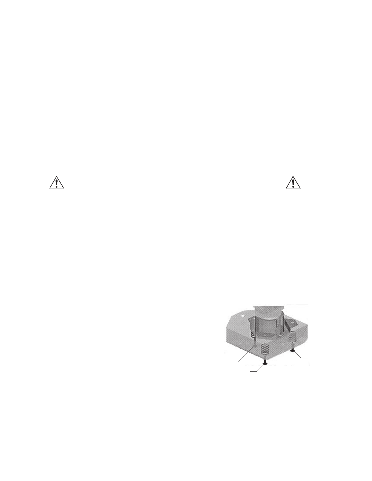
d. If the lamp is not exactly centered in the circle, using a phillips screwdriver, set the alignment by
alternately loosening or tightening each of the three adjusting screws located at the bottom of the
holder block (see illustration) until the bulb is perfectly aligned.
NOTE: There are (6) screw heads visible
on the bottom of the bulb holder block.
The screws with lockwashers are mount-
ing screws; the screws with flatwashers are
the three adjusting screws.
Adjusting
Screws
1
3
2
CAUTION: adjust each screw very slowly in order to prevent the bulb from touching
the optical system, as direct contact could cause both the bulb and the lenses to explode.
Once the alignment is correct you can start using your followspot.
6
Page 9

14. FOCUSING
This fixtures features a variable beam angle from 8° to 22°. The variable beam is altered by adjusting the
front and rear zoom lenses in relation to each other. The front lens defines the beam spread (spot size),
the rear lens the focus degree of “softness” or “hardness” of the beam edge or shutters.
15. FADE-OUT MECHANICAL DIMMER (DOUSER)
The followspot is fitted with an adjustable mechanical dimmer to dim and finally douse the beam. The
fade-out/douser mechanical control lever is located between the two zoom lenses.
16. CLEANING AND MAINTENANCE
To insure maximum performance of the product, regular maintenance service should be carried out.
Please make sure the spotlight has cooled and is disconnected from its power source when doing this.
General Maintenance
• Clean all reflective parts such as reflectors, mirrors and lenses. Open the housing if necessary.
• Check the bulb and the lenses and replace any visibly damaged component.
• Clean air ducts and fans in order to allow proper ventilation.
• Check internal and external wiring and replace any cable which appears to be damaged by heat or
mechanical agents.
Cleaning of Optical Components
• Lamphouse lenses:
a. Remove the bulb.
b. Open the lamphouse compartment access panel by removing the two 4mm cross-head screws on the
top of the lamphouse tube.
c. Dismount the lens/mirror assembled block by removing the two 5mm cross-head screws.
d. Clean the lens/mirror assembly with a soft cloth through the top opening. To remove the lens/mirror
assembly from the lamphouse, see “Replacement of Cooling Fan” below.
• Zoom lenses:
Access the lenses through the sliding doors located on the bottom of the lens tube and clean with a
soft cloth.
Replacement of Cooling Fan
a. Remove the bulb.
b. Open the lamphouse compartment access panel by removing the two 4mm cross-head screws on the
top of the lamphouse tube.
c. Remove the (8) tap screws from the outer perimeter of the lamphouse back cover plate. Pull the back
cover rearward, and the lamphouse base will slide from the housing, allowing access to the fan.
7
Page 10
16. CLEANING AND MAINTENANCE (continued)
Replacement of Zoom Lenses & Fade-Out/Douser
Access the mounting screws through the sliding doors located on the bottom of the lens tube.
17. SPARE PARTS
All components are available as spare parts. We strongly recommend you always use original factory
components as replacement parts. Please refer to your Strong Entertainment Lighting dealer should you
need to order and/or replace any part of the unit.
18. WARRANTY
Our warranty covers all structural and manufacturing defects for one (1) year from the date of purchase.
If a unit proves defective, contact the Strong Entertainment Lighting dealer who supplied the product
and report the serial number of the unit.
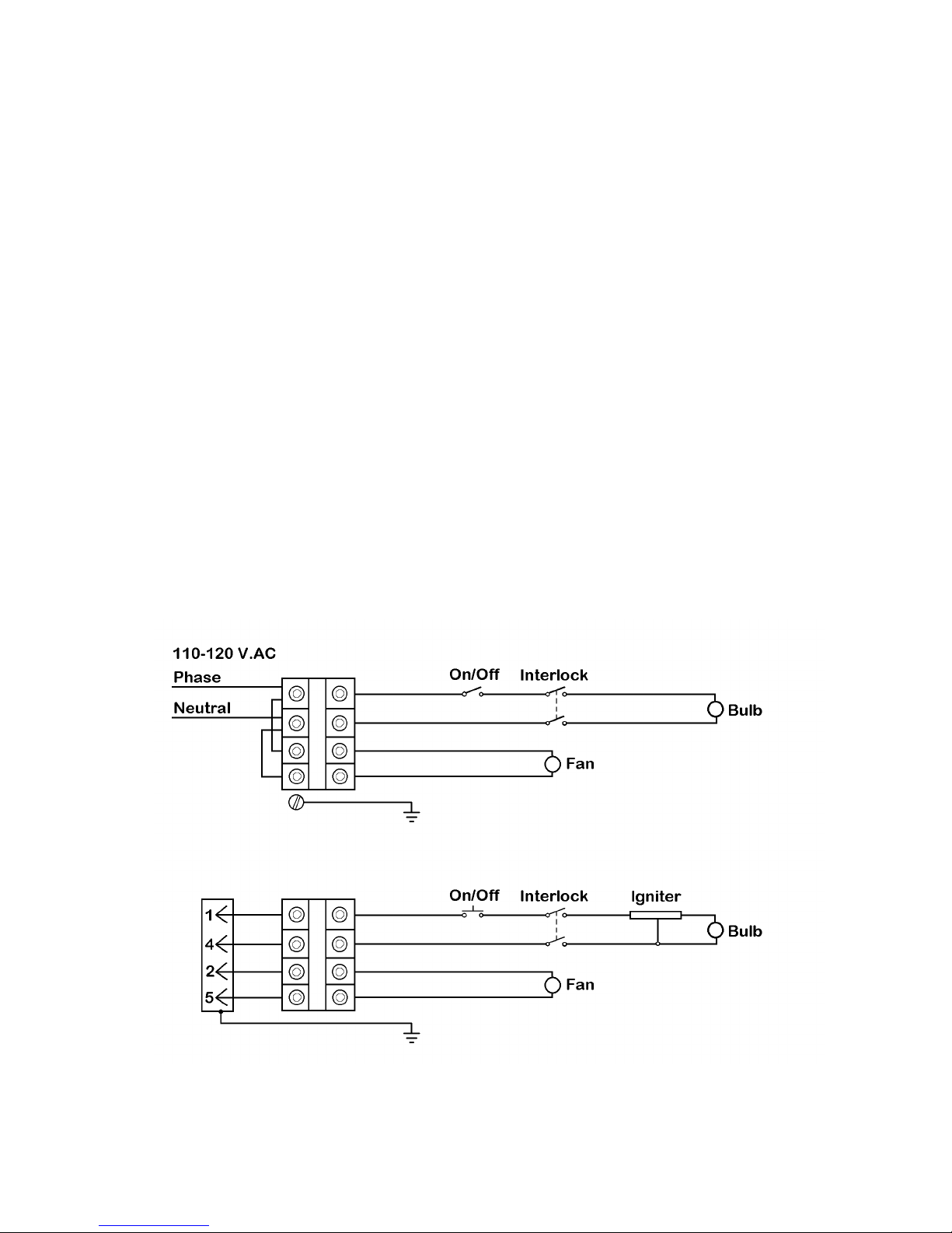
19. WIRING DIAGRAMS
Canto 1000, 2000 (Tungsten-Halogen)
Canto 575, 700, 1200 (Metal Halide)
8
Page 11
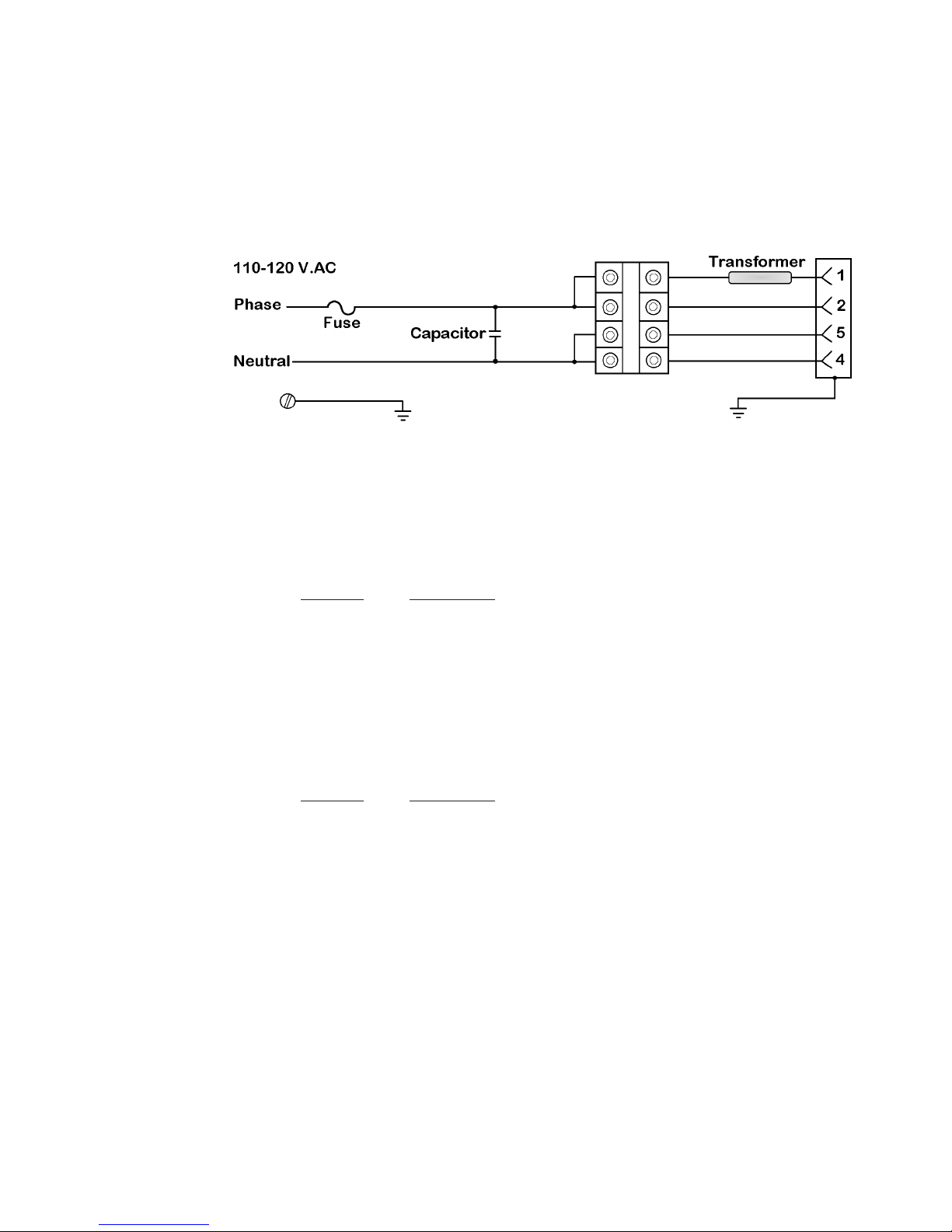
19. WIRING DIAGRAMS (continued)
Metal Halide Power Supply Unit
20. PARTS LIST
Canto Accessories
Part No. Description
20102401 Tripod Floor Stand
20102200 Spare Spigot/Truss Pin, for 28mm
20105006 Color Boomerang
20100106 Spare Color Frame
20100807 Gobo Holder, A/B Size
Canto Replacement Parts
Part No. Description
20015781 Power Supply Unit, 575 Watt Metal Halide
20017081 Power Supply Unit, 700 Watt Metal Halide
20018581 Power Supply Unit, 1200 Watt Metal Halide
20100707 Iris
80FO5029 Fade-Out/Douser
80LE4127 Rear Zoom Lens
80LE1450 Front Zoom Lens
Lamphouse Reflector & Lens Assembly
80SP0068 Reflector
80LE6068 Condenser Lens
80LE3100 Convex Lens
9
 Loading...