

Page 1
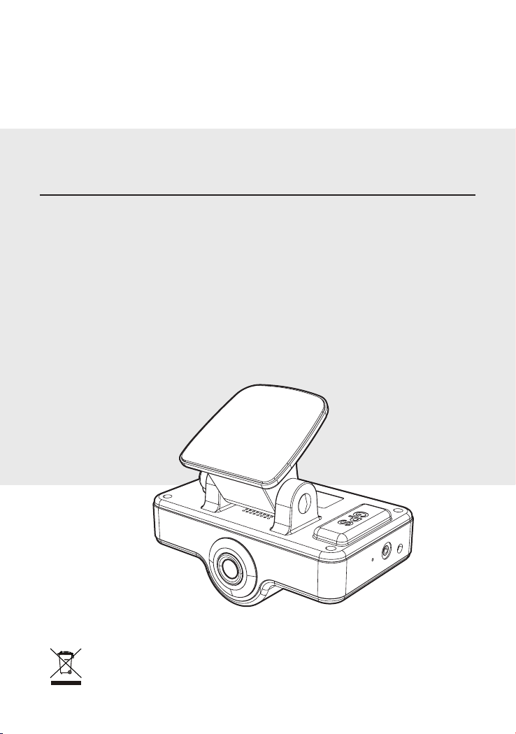
2 CH DRIVING VIDEO RECORDER
Instruction Manual
DR-200
Thank you for purchasing this product.
For proper usages and application,
Please read this instruction manual thoroughly.
PRINTED IN KOREA ver. 1.0
* Design and Specifications are subject to change without notice.
Page 2
2
3
Contents
2 Channel DRIVING VIDEO RECORDER
Please read the “Safety Rules” carefully before using this product. Following the safety rules pre-
Safeguard Instructions
1. Feature
................................................................................................................................... 5
2. Box Contents
3. Installing the recorder in your vehicle
Recommended Installation Location for DVR
Recommended Installation Location for the External Button
Wiring diagram for DVR
Detailed procedure of installation for DVR
How to Install the External Button
4. Components and their functions
5. Preparations for Operation
Inserting the SD card
Removing the SD card
6. Operation
........................................................................................................................... 13
Power ON/OFF
System reset(restart)
Video recording
Operation of the External button
7. PC VIEWER Manager
How to install PC VIEWER Manager
How to execute PC VIEWER Manager
About user interface
File list
Movie control
..................................................................................................................................... 19
...................................................................................................................... 21
Mode Change / Screen capture
G-SENSOR / Checking the route / checking GPS info.
Configuration
...................................................................................................................... 24
8. Specifications
...................................................................................................... 3
...................................................................................................................... 5
................................................................. 6
........................................................ 7
......................... 7
..................................................................................................... 8
.............................................................. 8
.............................................................................10
......................................................................... 11
..................................................................................... 12
....................................................................................................... 12
.................................................................................................... 12
..................................................................................................................... 13
........................................................................................................ 13
.................................................................................................................. 14
.............................................................................. 15
.................................................................................................... 16
........................................................................... 16
...................................................................... 17
........................................................................................................ 18
................................................................................. 22
..................................... 23
................................................................................................................... 27
vents users from damages related with the misuse of the product. It is very important to follow
these safety rules. We state “Caution” and “Warning” to clarify any potential risk for a damage
associated with the misuse of the product.
Safeguard Instructions
2 Channel DRIVING VIDEO RECORDER
NOTICE
CAUTION
WARNING
CAUTION
Do not place near magnet.
- It may cause malfunction and trouble.
Do not shock to the product.
- It may cause damage or malfunction for product.
GPS function needs loading time when it power on.
- It needs from few seconds to minutes depending on signal receipt environment.
Before pull SD Card out, please check the power o status.
- If you pull SC Card out during power on status, it may cause malfunction or data loss.
Do not put a foreign substance in to SD card slot.
- It may cause a malfunction or SD card inserting problem.
Please use only authenticity SD card
- Manufacturer do not have a responsibility for not in usage of adulterated card.
Do not touch SD card with wet or oily hand.
- It may cause malfunction due to card damage.
When install GPS antenna, be careful not to be surrounded by obstacle.
- It may cause problem on GPS signal receipt rate.
Push the SD card fully.
- It may cause a malfunction.
Attach the product recommended place.
- If it is installed other place, the image may be swerved.
In case of metallic tinting on front window may cause telecommunication problem or
poor recording quality.
- In metallic tinting car may cause GPS signal receipt problem.
This information is for user’s reference for better usability.
This information is for preventing damage or shorten the life time
of the products.
This information is for preventing bodily harm or even death and
use should follow this safety rules.
Page 3
4
5
Feature
1
2 Channel DRIVING VIDEO RECORDER
· All car accident records
WARNING
Should install while power o. (After install products, connect DC jack)
- It may cause to electronic shock or malfunction.
Unplug product when do not use for a long time.
- It may case re by short circuit due to heating.
Do not place near of air bag eective range.
- It may cause malfunction of air bag or accident, injury due to hitting monitor by air bag.
Keep clean dust on power socket.
- It may cause electronic shock and re by bad connection.
Do not place where vibration and shock.
- It may cause throw down and then malfunction and accident.
Do not use in problem condition as like smoking, smell something burn.
- It may cause re. Stop to use and make inquiries to agency.
Do not pull cord with a jerk, should catch a plug and pull. Do not use damaged cord.
- It may cause cord malfunction, electronic shock and re.
Do not clean exterior with volatility or oily solvent. Neither keep touching rubber and
plastic for long time. - It may cause change of surface, fall of paint, malfunction and re.
When clean exterior, power o and wipe with dry cloth.
- Wet cloth may cause a electronic shock.
When the power cable cord touches a metal case, cover it with a friction tape.
- Short circuit or disconnection of wire may cause a re or accident.
Before installation, always turn o the engine.
- It may cause an electronic shock or defect.
Do not operate the product while driving.
- It may cause an accident. Stop in a safe place and operate.
Do not disassemble, repair and remodeling.
- It may cause malfunction and injury, can not get warranty.
- Make inquiries to agent for repair and checkup.
Do not put a pin or needle on the hole or crack in the body.
- In case of inserting them, stop to operate, it may cause electronic shock, re and malfunction.
Do not put the product in place where sudden temperature increasing and should use
on optimum voltage, temperature and humidity.
- It may cause to electronic shock or malfunction.
Attach the product on the front window rmly.
- Clean the front window and x it rmly, otherwise it may be detached due to temperature/humidity/dust/shock.
· Dual mode recording (indoor / outdoor)
· Wide angle of view supported (Inside : 140° / Outside : 130°)
· Emergency button / Internal IR-LED / Ambient light sensor built-in
· Voice recording supported during indoor video recording
· Speaker Alert
· Built-in GPS module
· Built-in 3G-Sensor (Front/Rear, Left/Right, Up/Down shock sensing and recording)
· SD CARD use (Max. 16GB)
- If the recording image exceeds SD Card capacity, it deletes images from the oldest file
and records continuously.
· Emergency battery equipped
· Free Voltage (DC 12V~24V)
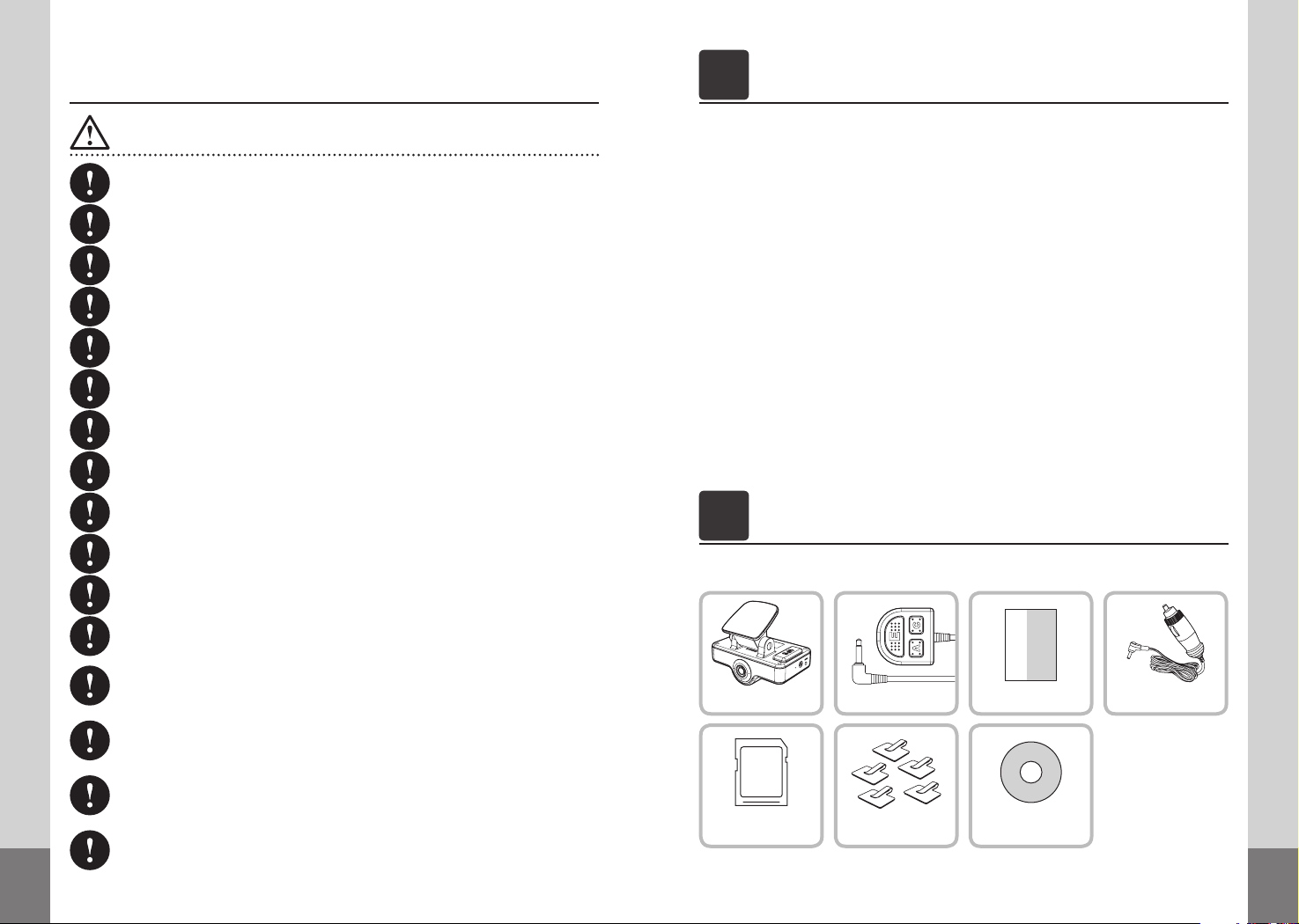
Box Contents
2
2 Channel DRIVING VIDEO RECORDER
* Before use this products, please check below contents. If there is something missing parts,
please contact sales agent.
External ButtonDVR Cigar CableInstruction Manual
SD CARD
Accessories
PC VIEWER
Manager Install CD
Page 4
6
7
Installing the recorder in your Vehicle
3
2 Channel DRIVING VIDEO RECORDER
Prior to installation, check the followings :
- To ensure safe installation, always perform installation procedures in a bright place
with no vehicle traffic.
- Before installation, always turn off the engine and pull out your car key.
- DO NOT use any other cables than the power cigarette cable included.
- The glass to be equipped with the camera should be kept clean.
- For vehicles with excessive window tinting, the recorded images may appear dark.
- Do not place near radio wave obstacle and leave a space with high-pass, navigation
and so on.
- If use navigation and vehicle monitor, the image could be reflected on the front glass
and it might effect on the recording quality. To prevent this problem, please set the
direction not to be reflected the image.
- If the IR-LED of indoor camera is adjacent to a room mirror (rear view mirror), the IR-LED
will be affected by light reflecting from the back of the room mirror during video recording at night, deteriorating the quality of recording. Thus, please install this device
with an appropriate distance between your room mirror and the IR-LED.
Front Glass
Tinting section
Room mirror
Keep horizontal
Outdoor
Double-sided
Adhesive tape
Front Glass
Room Mirror
Outdoor
Tinting section
Double sided
Adhesive tape
DVR Body
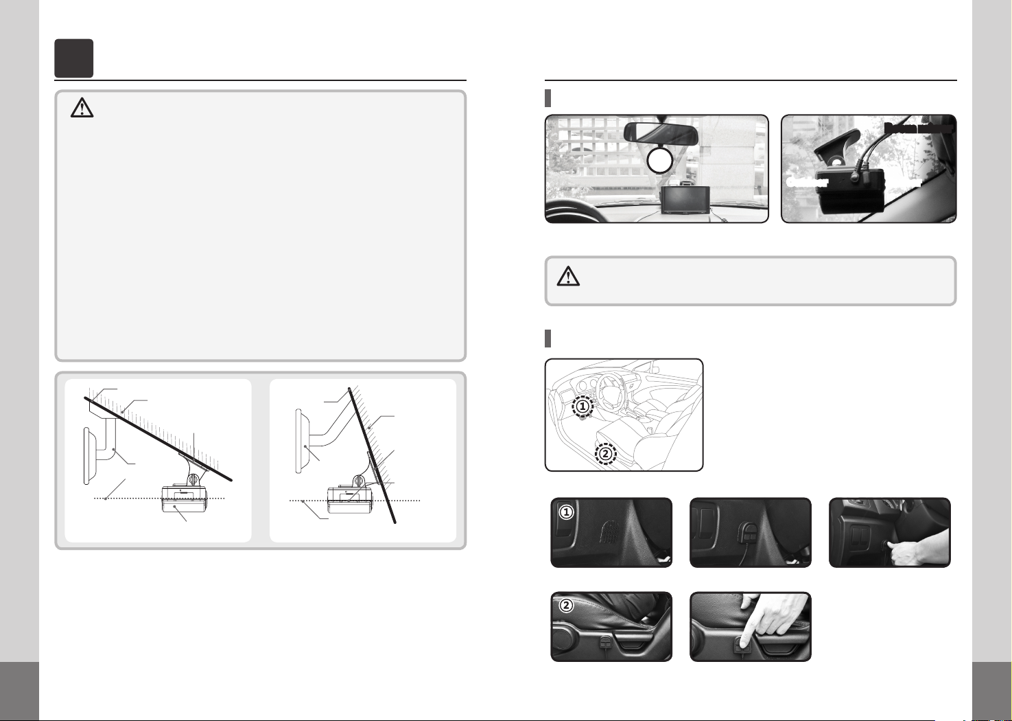
Recommended Installation Location for DVR
Room mirror
Outdoor Indoor
If installed at the center of the glass window in the front of the room mirror, optimal recorded
images can be obtained.
If installed slantingly (towards the right or left), the optimal quality of image
cannot be guaranteed. Pay special attention to the recommended installation
location as possible.
Recommended Installation Location for the External Button
* Emergency Button must be placed in a highly ac-
cessible location where the driver can push the button readily and quickly when he or she encounters
an unexpected situation, and the following figures
show the recommended locations in consideration
for such the situations.
* The installation location and wiring of the button
may vary with the preferences of user.
<If installed at the left bottom of steering wheel>
Indoor
1. As shown in the figure above, place this device so that there is no obstacle to the front view
and that the viewing angles of indoor/outdoor lens do not overlap with tinting sections.
2. Thoroughly remove impurities and dust from the desired area to be attached by the adhesive
side of double side adhesive tape, before attaching it. If any impurities or dust remain, it may
cause this device to come off. This event while driving may lead to a traffic accident.
3. When fixing the double side adhesive tape provided, do not fix it on heat rays of the windshield. Otherwise, heat rays may be damaged when removing it. Be careful.
4. Always install this device so that it is level as shown in the figure above. Otherwise, you cannot
obtain normally recorded images.
DVR Body
Car Bus or Truck
Indoor
Keep Horizontal
<If installed at the left bottom of driver’s seat>
Page 5
8
9
Wiring Diagram for DVR
* The above wiring diagram may vary with the kind of vehicle.
Once wiring and installation have been completed, check the followings:
- After installation, get the engine started. Then, the LED on the POWER will light up, which indicates normally completed installation.
- If the LED on the POWER fails to light up, check the cable connections and subsequently, remove dust or impurities from the cigarette socket.
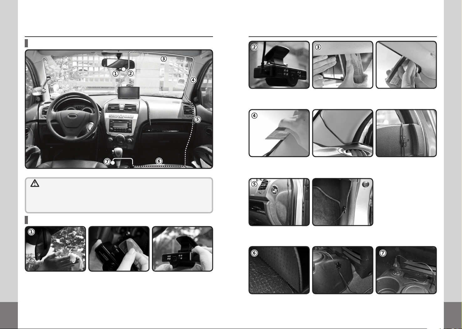
Detailed procedure of Installation for DVR
Once it has been at a level with the ground after angle adjustment, connect the product to the cigarette jack.
Push in the cigarette cable in the slit between the front glass and the roof. At this time, use a thin and hard
object for convenient handling.
Continue to arrange the cable up to the joint between the front glass and the side frame. If required, use the
clips for cable arrangement supplied with the product. After cable arrangement around the front glass, open
the front seat door.
Draw the cable out between the front seat door and the side of dash board, and with the enclosed clips for
cable arrangement, fix it down as far as the front seat door frame and beneath the footing. At this time, too
loosely arranged cable may be damaged when opening/closing the door or getting into/out of the vehicle.
Prior to installing the product, remove thoroughly any impurities and dust from the place of front window for
adhesive tape. Peel off the protective film of double-sided adhesive tape on the stand, and firmly attach to the
glass window in the front of the room mirror. Following attachment, release the stand fixing lever to adjust it
so that it is at a level with the ground, and tighten firmly again.
* Regarding the attachment position of the stand, avoid the heating wire and coating (tinting) areas on
the top of the front glass. If installed in the tinting area, the quality of recording may be deteriorated and
heating wires may be damaged when removing the stand.
Slightly lift up the mat under the front seat, and then arrange the cable across the seat. After arrangement, put
the mat in place again, pull out the cable to the side of the console box, fix with the clips for cable fixation, and
put the cigarette plug into the cigarette socket.
Page 6

10
11
Components and their functions
4
2 Channel DRIVING VIDEO RECORDER
How to Install the External Button
First connect the cable for Emergency Button to this device, check the installation location of the button, and
arrange the cable in the same manner as for cigarette cable - inserting it into the groove joint between the
windshield and the roof.
Continue to arrange the cable as far as where the windshield meets with the side frame. If necessary, use
cable-arranging clips provided with this device. Once cable arrangement for the windshield has been completed, open the front seat door.
Draw out the cable through the
gap between the front seat door
and the side of dash board, and
use the cable-arranging clips supplied with this device to fix it down
to the rim of front seat door and
the footing.
At this moment, too loosely arranged cable may cause the cable to be caught and damaged when opening/
closing the door or getting into/out of your car.
Bring out the Velcro tape provided with this device, detach each sticker from its back, and attach one side to
the button and the other side to the recommended installation location.
14. Emergency recording button
15. Voice recording button
16. Indoor camera ON/OFF
External button
5. Microphone
3. IR-LED / Ambient light sensor
2. Indoor camera lens
4. Status indicator LED
1. Outdoor camera lens
2. Indoor camera lens
3. IR-LED, Ambient light sensor
4. Status indicator LED
5. Microphone
6. SD-card slot
7. Reset
8. External button port
9. DC IN
10. Speaker
11. Stand
12. Standing xing lever
13. Internal GPS
14. Emergency recording button
15. Voice recording button
16. Indoor camera ON/OFF button
11. Stand
13. Internal GPS
12. Standing xing lever
7. Reset
1. Outdoor camera lens
6. SD card slot
8. External button
port
10. Speaker
9. DC IN
Lens intended for outdoor imaging(130°)
Lens intended for indoor imaging(140°)
IR-LED(x7) and ambient light sensor for night
Power / In-CAM / Audio LED
Built-in Microphone
A slot intended to insert the SD card
System reset button
A port intended to connect the External button
A port intended to connect the power cigar cable(DC 12~24V)
Output speaker of all kinds of auditory warning signals(MONO)
Stand for xation on glass window(double-sided adhesive tape)
Stand / Product-xing lever(enabling to adjust its angle)
Internal GPS
For emergency recording and screen capture
Voice recording ON/OFF
Indoor camera ON/OFF
Page 7

12
13
Preparations for Operation
5 6
2 Channel DRIVING VIDEO RECORDER 2 Channel DRIVING VIDEO RECORDER
Operation
Before using the SD card, check the followings:
- Always use the original SD card only. If not, data loss may happen.
- The SD card can be inserted regardless of the power On/Off status of the product. As soon
as it is inserted, it will reset the internal software and then operate.
- To remove the SD card, first turn off the vehicle engine, and check that the GPS(POWER)
LED lights out (not more than 20 sec. required). Then, remove the SD card. If remove SC
card on power on status, it sounds beef and can not complete recording. And it may cause
recording image delete or not be able to use SD card anymore.
Inserting the SD card
Open the lid of card slot, and
insert as shown in the figure.
Push fully in the card until it seems
to be caught by something inside.
Once the card has been com-
pletely inserted, close the slot lid.
Removing the SD card
the SD card. Then, it will come out.
Pull fully out the SD card. Open the slot lid, and press gently
As the incorrectly inserted card may cause malfunctions, always push fully
in the card to the utmost with your fingertip. Be careful not to allow your
hands or any impurities to touch the card terminals. Otherwise, data loss
may occur.
After removing the SD card,
close the slot lid.
Before operating this product, please take case below point.
- Do not operate on driving.
- Recording is possible when SD card is inserted.
- If remove SD card while recording, some part of image might be deleted.
Power ON/OFF
This product has no power on/off button. To power on, start up the engine while the power cigarette
cable has been connected to the body. Then the power on with beep sound.
If the engine is turned off, the POWER LED will remain lighted up for at most 20 seconds (powered by
batteries), and will light automatically out, and will light automatically out with beep sound.
* While recording function finishes, it is powered by the batteries built in. After recording function
finishes, the file is securely saved followed by power off.
* This product is a model integrated with GPS antenna. If powered on, GPS signals will be first de-
tected with signal sounds. Then, GPS functions will enable to expect or calculate user’s driving
route, speed, duration and distance.
After inserting the SD card, start up the vehicle engine. Then, the product
will power on. At the same time, while auditory signals are heard, it will
detect GPS signals. It will detect GPS signal with beep sound.
• Within the GPS coverage : Green Power LED lamp will light up.
• Out of the GPS coverage : Red Power LED lamp will light up.
A video file name is composed of YYMMDD (year-month-day [date]) and Hour/
Minute/Second. If any GPS signals have been normally detected, time settings
are automatically made. However, in the event of poor GPS signal reception, the
actual time will be different from the recording time. In this case, it is impossible
to check the accurate time in an emergency. For the reason, always make time
settings in manual mode through Configuration window of PC VIEWER Manager prior to use. (Refer to P.25)
System reset (restart)
System reset function is used in the event of any fault(s) during operation or when it stops
suddenly.
Using a thin object(e.g., pin), press down the RESET button at the
side of the product. Then, it will be reset and restarted.
Page 8

14
15
Video recording
Once installation and wiring procedures have been completed, start up the engine with the SD
card inserted. Then, it will power on without any other additional operation, and recording will
start simultaneously.
* Factory Default: Dual Recording Mode (User can change recording mode on Recording set-
ting / refer to p.25)
Recording mode & time
* Normal Recording : Independent of events, it continues recording at intervals of 1 min.
1 min. Continued...
* Event Recording : It performs recording just for 10 seconds before and 5 seconds after an event
Event recording starts with beep sound.
* Dual Recording : Both normal recording and event recording are used. If any event (impact) is de-
Ex) If an event happens 1 minute and 40 seconds after starting recording:
Save as a Nor-
mal recording
file(1 min.)
When the recording image is over SD card capacity, it deletes image orderly from the oldest one. And
normal and event recording rate is allocated 6:4 from SD card capacity.
ex) In case of 2GB SD card
Recording mode
Normal recording
Event recording
* The words, ‘an event happens’ mean to detect any impact when it is given. The higher is the sensi-
tivity, finer shocks or impacts are detected. On the other hand, the lower is the sensitivity, simply
strong shocks or impacts only are detected. It is possible to adjust the intensity of detection (sensing) in the PC VIEWER Manager.(refer to p.25)
1 min. 1 min. 1 min. 1 min. 1 min.
(accident) happens. (15 seconds in total)
10 sec. before
an event
tected during normal recording, normal recording will stop and instead, event
recording will start. After event recording, normal recording will resume.
Event recording Normal recording
10 sec. 5 sec.
The portion other than images before 10 seconds from 1 minute and 40 seconds
after an event happens will be saved as a file of normal recording (30 seconds).
Saving folder
Normal
Event
Event
Event
1min. and 40 sec.
About 1.2GB (If it is over 1.2GB, it deletes image orderly from oldest
About 0.8GB (If it is over 0.8GB, it deletes image orderly from oldest
5 sec. after
an event
1 min. 1 min. 1 min.1 min. 30 sec.
Maximum storage
one and record new one.)
one and record new one.)
Normal recording section
Event recording section
Depending on the mode of recording, REC LED turns green and blinks.
• Normal Recording: The LED blinks at very short intervals once per second (Green).
• Event Recording: The LED blinks five times per second (Red).
• Indoor Recording: IN CAM LED lights up.
• Voice Recording: AUDIO LED lights up.
Operation of the External button
• Emergency recording
Emergency recording function is intended to activate manually recording in an unexpected event
or when it is necessary to save images at discretion. Such images will be saved in [EVENT] folder of
the SD card.
Emergency
Recording
Briefly press down
(within 1 sec.)
* If Emergency Button (E) is pressed while indoor recording turns on, both outdoor and indoor
recordings will be simultaneously enabled (activated); while indoor recording turns off, outdoor
recording only will be enabled.
• Instant Capture
Instant capture function is intended to photograph and save the front view in an unexpected event
or when it is necessary to save the taken photographs at discretion. Such photographs will be saved
in [CAPTURE] folder of the SD card.
Instant
Capture
Press and hold down
(for 1 sec. or longer)
• Indoor Recording ON/OFF
Indoor
Recording
ON/OFF
* If the mode changes in the course of recording, it will take about ten seconds to operate in the
changed mode. Note that recording function will be disabled during this time.
• Voice Recording
Although this product has “OFF” setting for voice recording as factory default, voice recording will
start by pressing shortly the Voice Recording Button [A] during operation. (It is also possible to set
this function in the PC VIEWER Manager Configuration window.)
Briefly press
down
(within 1 sec.)
- Simply (briefly) press down Emergency Recording Button [E]
during operation. Then, manual video recording will be enabled
with beep sound.
- Recording procedures are same as those for event recording.
(10 seconds before / 5 seconds after pushing the button)
- This function will be disabled during event recording.
- Press and hold down Emergency Recording Button [E] during
operation. Then, manual photographing will be enabled.
- It sounds click, saved as JPEG file format.(*.jpg)
- If your vehicle runs fast or at night, the quality of photos taken
may be poor.
Press the [C] Button during operation to light
up IN CAM LED and at the same time, to activate indoor recording. Press it once again to
turn IN CAM LED off and at the same time, to
make indoor recording disabled.
Shortly press the Voice Recording Button [A]
during operation to light up AUDIO LED with
indoor recording activated. If pressed once
again, AUDIO LED will turn off with indoor
recording inactivated.
Page 9

16
17
PC VIEWER Manager
7
2 Channel DRIVING VIDEO RECORDER
* Recommended PC specifications for PC VIEWER Manager
CPU : Pentium 1GHz or more
OS : WINDOW 98/ME/2000/XP/VISTA
Memory : 512MB RAM or more
HDD : 500MB or more supported
What is PC VIEWER Manager?
It is an exclusive software application for DVR only, designed to enable its user to check the video
contents recorded during driving as well as to check driving route/GPS data/shock graphs.
How to install PC VIEWER Manager
It needs to install for PC VIEWER Manager.
Insert enclosed CD to PC and install the program as below after double click “setup.exe” file.
In case of changing install
route, please click it.
How to Execute PC VIEWER Manager
Double click Camos DVR icon then below screen is appeared and PC Viewer Manager is executed.
Loading Screen
Once the SD card has been normally connected to your PC and the PC VIEWER Manager is running, video data saved in the card
is displayed in the file list.
When it is executed above image is appeared.
After loading is completed, the program is executed automatically.
Input password
Play a file
First select a desired video file to be played in
the file list, and click PLAY Button. Then, the
selected video file will be played.
When installation is finished,
directly to the icon is created.
Double click the icon and
execute the program.
When you set the password on setting menu
this screen is appeared. Input a password,
then program is executed. (Refer to P.26)
If the password is not correct, above message
is appeared.
* If any recorded video file does not appear
in the file list, please check again that the
SD card has been correctly connected to
your PC.
Page 10

18
19
About User Interface
Execute camosDVR.exe file, and PC VIEWER Manager will be run as shown below.
1. Play Screen
2. 3G-sensor / Play Position
3. Volume Control
4. Image Control
5. Play Speed Control
6. Exit
7. Minimize
8. File List
9. Extend File List
10. Map Info.
11. GPS Info.
12. Screen Capture
13. Mode change
14. Conguration
15. Program Info.
A eld where recorded images are viewed
Indicates 3G-sensor information display and play position.
Controls the volume. (Mute / Volume +,-)
Stop/Previous File/Backward/Play(Pause)/Forward/Next File
Controls play speed. (1/4 x speed ~ 4 x speed)
Exits the program.
Minimizes the program window. (into the Task Bar)
Displays a list of the playable les saved in the SD card.
Shows additional le lists.
Displays the driving route on the map.
Displays the current GPS info. received during driving.
Captures the screen being played as JPEG le.
The mode can be changed to either 1CH or 2CH.
Displays conguration window where the user can make detailed settings.
Displays the version and information on the software program.
File list
1. File List
2. Select
3. Extend List
4. Sort
5. Import
6. Export
7. Delete
Displays the files saved in the
SD card.
Selects and deselects a file.
Extends the file list into an additional window.
Sorts All/Normal/Event Files.
Imports a desired video file.
Save a selected file in the hard
disc.
Deletes a selected file in the SD
card.
1. Select file
1. There are Select buttons (tick boxes) in the front of each file name. (No. 2 in the above figure)
2. Click a Select button, and the file will be selected. (Multiple files can be selected)
3. Click the top Select button, and all the files will be selected; click again, and all the files will be
deselected.
2. Export (Save in the hard disc)
1. Select a single file or several files desired to be saved in the hard disc, in the file list.
2. Next, click [Export] button. Then, save it in “My documents\DVR backup\”.
When the file is saved, left message is appeared. (it
disappears after 1 second)
Unless choice a file and press [export] button, left
message is appeared. (it disappears after 1 second)
3. Import file
1. Click [Import] button in the file list.
2. Once Explorer window appears, select a video file(s) and then, click OK button.
4. Delete file
1. Select and tick a single or multiple file(s) desired to be deleted in the file list.
2. Next, click [Delete] button, and the file(s) will be permanently removed from the SD card.
* Note that it is impossible to recover any deleted files which have not been saved in the hard disc.
When file is deleted, left message is appeared. (it disappears after 1 second)
Unless choice a file and press [delete] button, left
message is appeared. (it disappears after 1 second)
Page 11

20
21
5. Sort file
1. Enables the user to sort All/Event/Normal files in the file list.
2. Click [ALL], and all the files in the SD card will be displayed in the list.
3. Click [EVENT], and EVENT files in the SD card will be displayed in the list.
4. Click [NORMAL], and NORMAL files in the SD card will be displayed in the list.
6. Extend file list
Movie control
Normal file list screen
1. Click [Extend List] button to view more
files at a time.
2. Click [Extend List] button to extend
the list, and a separate window of file
list will appear on the right side. Click
it again, and normal file list screen will
be returned.
Extended file list screen
Every video file name consists of [YYMMDD_Hr/Min/Sec_INDEX_RECORDING MODE_OUTDOOR/INDOOR]. Index plays the role of grouping indoor/outdoor files saved at the same
point of time. I represents normal files; E event files; 1 outdoor; and 2 indoor.
Ex) 090312_180426_002_I_1.mp4: indicates a normal file (outdoor) saved at 18:04:26 on March 12, 2009.
090312_180427_002_I_2.mp4: indicates a normal file (indoor) saved at 18:04:27 on March 12, 2009.
* The two files above are outdoor/indoor files saved at the same point of time.
1. Play / Pause
2. Backward / Forward
3. Previous/Next File
4. Stop
5. Set Play Speed
6. Volume Control
7. Play Location
8. Play Duration
Plays and pauses the selected file in the file list (toggle button)
Plays the screen several seconds after(before) the current image being played.
Plays the previous (next) file in the file list.
Stops the file being played.
Sets the play speed of video being played. (1/4 X speed ~ 4 X speed)
Controls the volume and sets mute function.
Displays the current play location in the image being played.
Displays play duration/ total running time.
1. Play options
- Normal Play: Select a desired file to be played in the file list, and click Play button.
- Skip: Click Backward/Forward button, and playing will be skipped at regular intervals.
- Play Previous/Next File: Click Previous/Next File button, and the previous/next file in the file list
will be played.
- Control Play Speed: Control play speed to view slowly and carefully important scenes or to skip
unnecessary scenes. (1/4 x speed ~ 4 x speed)
- Volume Control: Drag Volume Control button to control the volume (for higher volume, drag it
to the right). Click Speaker button, and Mute function will be activated; click again, and it will be
returned to the normal status.
Page 12

22
23
Mode Change
- The mode can be changed to either 1CH or 2CH.
- For 1CH, either outdoor or indoor screen will play in full screen mode.
G-SENSOR
If any shock is detected during video recording, timeframe-specific graphs will be generated
as shown below. On the following graphs, severely vibrating points (marked with dotted lines)
indicate the time when shocks are given.
- G-SENSOR graphs indicate vehicle vibration based on X/Y/Z axis.
(X axis: front/rear shocks / Y axis: left/right shocks / Z axis: up/down shocks)
- 3G-SENSOR sensitivity can be adjusted in Configuration menu. (Refer to P.25)
Outdoor screen Indoor screen
- For 2CH, both outdoor screen and indoor screen will play simultaneously in the following
form.
Screen capture
- Click Screen Capture button during playing, and the screen being played will be saved as an
image file.
- File format and Save path : JPEG / Same path as Export File List. [My documents\DVR backup\]
* Capture image can be display on other program of WINDOWS.
(ex. ALsee, windows image viewer, sketch board, etc.)
Checking the Route
It is possible to check driving routes on the
map.
1. You can move the map by arrow button.
2. You can zoom in/out by +/- button.
Checking GPS information
It is possible to check the current driving speed, time, direction and location information at the
time of driving.
Date and time at the time of driving
Driving speed at the time of driving
(Graphics)
Direction at the time of driving
Location at the time of driving
Driving speed at the time of driving
(Numerical value)
Page 13

24
25
Conguration
Click Configuration button to open the Configuration Window.
Recording settings Time / Unit settings Input User info.
Recoording Settings
· Setting recording quality
· Setting recording mode
· Setting the sensitivity of 3G sensor
* The optimal sensitivity of shock sensor varies with the kind of vehicle. Accordingly, first perform driving test with
the three levels of sensitivity, and then set the appropriate sensitivity.
· Setting recording option(s)
- High Quality : high-definition recording (heavy capacity)
- Normal Quality: medium-definition recording (mediate
capacity)
- Low Quality : low-definition recording(low capacity)
- Regular Mode: Regular recording at intervals of 1 min
- Event Mode: Recording activated only in an event
- Dual Mode: Event recording activated in an event during
normal recording / After event recording, it returns to normal recording.
- High Sensitivity:
- Normal Sensitivity: usual shocks are detected.
- Low Sensitivity: only significant shocks can be detected.
- Include Audio: Audio recording activated during video
recording.
even insignificant shocks can be detected.
(15 sec.)
1. Menu
2. Recording Quality
3. Recording Mode
4. Sensitivity of Shock Sensor
5. Recording Option
6. Speedometer Unit
7. Date/Time
8. World Standard Time
9. Time Option
10. User password setting
11. Apply to user password
12. Car Number setting
13. Default Setup
14. OK
15. Cancel
Selects recording setting menu and time/unit setting menu.
Sets the quality of recording.
Selects the mode of recording.
Sets the sensitivity of 3G-SENSOR.
Selects whether audio recording is included
Selects the indication units for GPS information speedometer.
Sets the current date/time.
Selects the world standard time.
Selects whether the set time will be applied to the product / summer time.
Set the password for PC viewer manager.
Apply the password for PC viewer manager.
When set the car number, it will be appeared on play screen.
Set up all the settings to factory default. (factory-default setting)
Saves the setting(s).
Cancels the setting(s).(Close)
Time / Unit Settings
· Setting speed unit
- Set the speed unit indicated in the PC VIEWER Manager.
· Setting data/time
- Set the current date and time. In the absence of GPS antenna (option), these settings will not be made automatically. Thus, always make the settings manually.
· Setting world standard time
- Set the local standard time
· Time option
- Apply to RTC: If this box is ticked, the date and time set
above will be applied to the product. (the time saved in
the product will be cleared.)
- Daylight saving(Summer time): selects whether summer time will be applied.
* It may be different from real time because the time information from checking “Apply to
RTC” is applied after SD card inserting.
* Though you adjust the time on setting mode, if it receives GPS signal, the time will be set
as GPS time.
Page 14

26
27
Input User Informations
· Input user password
- Input Password : Input password
- Confirm Password : Input password again for confirmation.
* Password is available maximum 8 digits. (special character, number and character are available)
The left message will be appeared unless input password
is correct.
· Apply to user password
- Apply to user password : This applies password to program, then it is available to use this program after input
password.
· Input car number
- Input Car Number : Input car number for user. The number will be appeared on play screen.
Specications
8
2 Channel DRIVING VIDEO RECORDER
Main Chips
Memory
Dual Camera
G-Sensor
Interface
Power
Recording
Dimension
Weight
Internal
External
GPS
Backup
Still cut
CLM6500
Serial and 512MB SDRAM
SD Card (1/2/4/8/16GB)
IN
30M pixel CMOS sensor (viewing angle : 140˚)
OUT
30M pixel WDR(Wide dynamic Range) CMOS sensor (viewing angle : 130˚)
Internal 3G-sensor
Internal GPS module
Power(DC 12~24V) / SD card slot /
External function button (Emergency, In Camera on/o, Audio on/o)
Main
Car Battery (Cigar jack) 12~30V
Li-Ion Polymer Battery
Video
640x480 (Dual 15fps, Single 30fps@max)
1024x768 (1 cut / 1 second)
105(W)x22(H)x67(D) / Lens(38.5) mm
156g (with Bracket)
* It needs to back up and format for SD card periodically.
Otherwise an error might be occurred when recording.
Page 15

INSTRUCTION MANUAL
 Loading...