

Page 1

CanTech
1
Ethernet card
Ether 4.1
Instruction manual
CanTech s.r.o.
Potoční ul. č.p. 2173/40
787 01 Šumperk
Tel.: +420 583 250 991
E-mail: [email protected]
Web: www.cantech.cz
IČ:64608557
DIČ: CZ64608557
zapsáno v OR KS Ostrava, oddíl C, vložka č 14112
ISO 9001:2008 a OHSAS 18001:2007
TAYLLOR & COX s.r.o.
Page 2

CanTech
2
CONTENT
1. Basic information.........................................................................................................................3
1.1 Description.............................................................................................................................3
1.2 Properties ...............................................................................................................................3
1.3 Expandability.........................................................................................................................3
2. WEB interface - internal WEB site..............................................................................................4
2.1 Status display .........................................................................................................................4
2.2 Network settings ....................................................................................................................5
2.3 Measurement settings.............................................................................................................6
2.4 Calibration..............................................................................................................................7
2.5 Alarm settings........................................................................................................................7
2.6 Email settings.........................................................................................................................8
2.7 Other settings .........................................................................................................................9
2.8 Output.....................................................................................................................................9
2.9 XML.....................................................................................................................................10
2.10 Reset the device .................................................................................................................10
3. SNMP protocol ..........................................................................................................................11
4. Modbus TCP..............................................................................................................................11
5. Program for setting – Eth4_setting.exe......................................................................................12
5.1 Introduction window and description of menu ....................................................................12
5.2 HTML – setting texts...........................................................................................................13
5.3 Config. – measurement setup...............................................................................................14
5.4 Mail – mail settings..............................................................................................................18
5.5 Output – output settings.......................................................................................................18
5.6 Custom alarms – set custom alarms.....................................................................................19
5.7 Discoverer – search device in network ................................................................................21
6. Program Ether4.exe....................................................................................................................22
6.1 Panel of Device list..............................................................................................................23
6.2 Alarms panel........................................................................................................................24
6.3 Values panel.........................................................................................................................24
6.4 Outputs panel .......................................................................................................................24
7. Upgrade firmware......................................................................................................................25
8. Connection.................................................................................................................................26
Page 3

CanTech
3
1. Basic information
1.1 Description
Ethernet card Ether4 allows you to monitor status of the four potential free inputs, measure the
temperature and supply voltage and control two relay outputs. Measured values and input status are
transmitted in digital form to master system via ethernet interface.
1.2 Properties
• Four potential free inputs for alarm transmission
• Possibility connection of measuring device with SO output (max 2)
• One input for digital temp. sensors (max. 16 sensors)
• Measurement of supply voltage
• Wide supply voltage range (9-60 V DC)
• Communication via Ethernet
• Communication protocols TCP(client, server), UDP, SNMP, HTTP, XML, SMTP, Modbus
TCP, SNTP
• Updating the firmware via ethernet
• Internal website to view current status and settings
• Possibility of entering custom alarms
1.3 Expandability
According to user requirements Ether4 card can be complemented with other hardware. The only
limitation is the number of terminals (24).
• 8 inputs for alarm transmission
• Measurement of 8 analog values using AD converters
• Calculating of consumption DC (max. two consumptions)
• Measurement of the temperature up to 16 sensors (16 – number of AD)
• Output options (operated manually or exceeding the limits)
- 2 relays (relay Fujitsu FTR-B3, max.60V DC,AC)
- 1 relay + 3 transistor outputs (transistor max. 60V DC, 50mA)
- 6 transistor outputs
Page 4
CanTech
4
2. WEB interface - internal WEB site
Using internal WEB site you can track inputs and measured values. It also allows you to view and
configure. To save the settings, you need to log username and password.
Default settings:
Name: cantech
Password: cantech
IP address : 192.168.1.103
Mask : 255.255.255.0
Gateway : 192.168.1.1
How to set dafault : pressing button Reset permanently lights green LED, to go out (about 7
seconds) will be reset to factory settings.
Note: the name is not change, only the password and Ethernet settings.
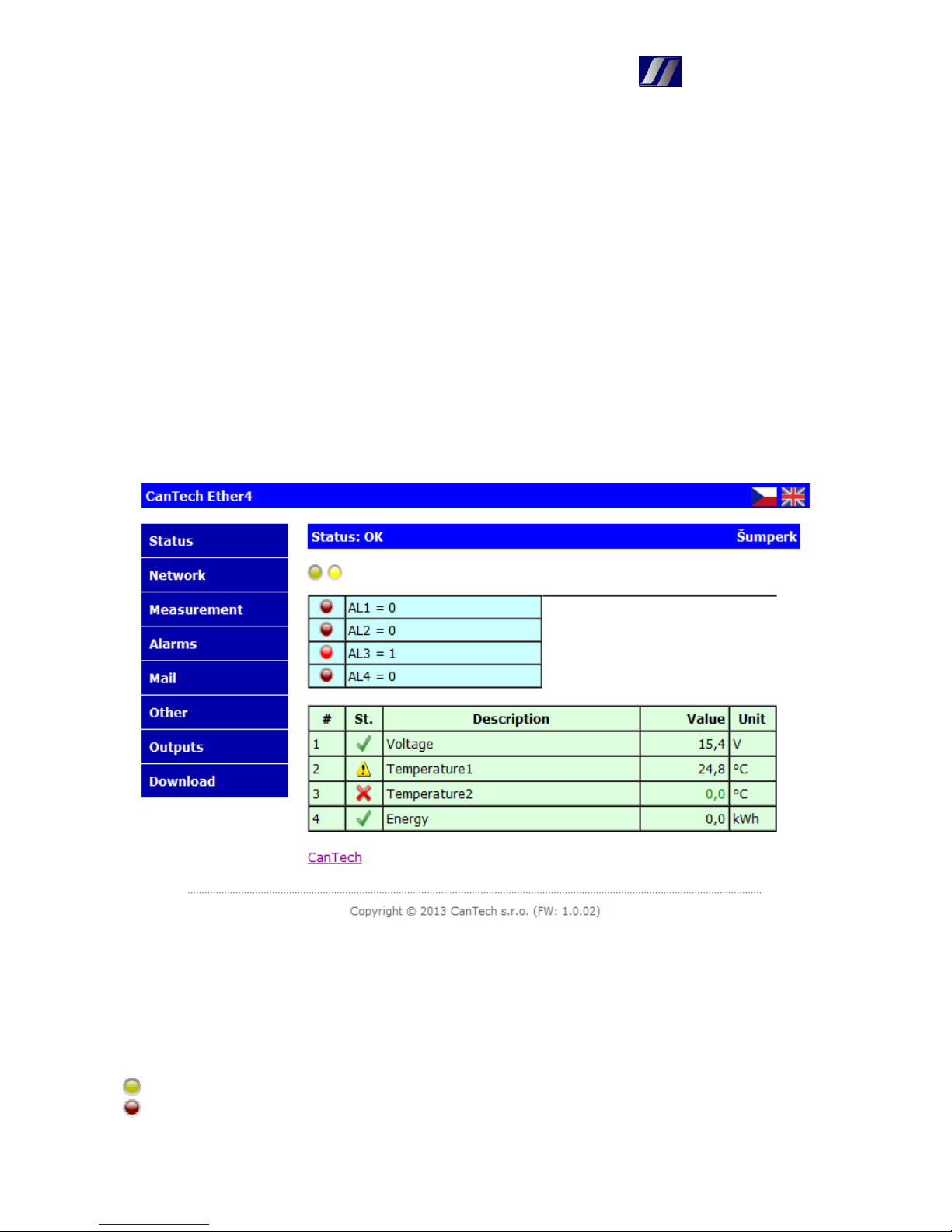
2.1 Status display
The status is periodically updated. The period is set on page “Other”.
Status … period is 0 and site updates are done manually <F5>
Status: OK … periodic data reading is fine
Status: Connection lost ... Ethernet card is unavailable
... custom alarm conditions. After you place your cursor on icon displays the name of alarm
... status of the digital inputs with description
Page 5
CanTech
5
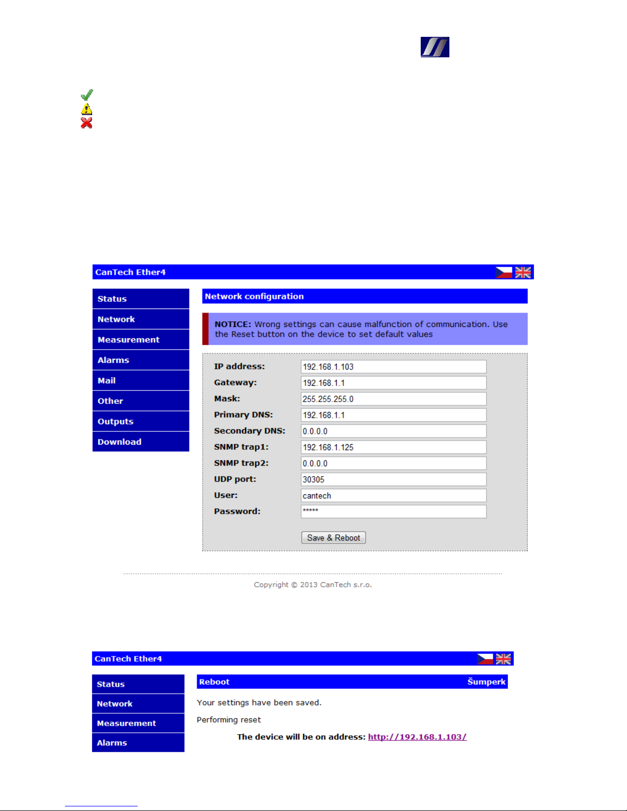
Table of values:
… measurement is fine and if watching limits, is within
… measurement is fine and the value is out of limits
… measurement error
Note: User alarms can not be set using the HTML. It is only possible using program
Eth4_nastavení.exe
As the temperature is measured with a longer period (800ms by default), the current
measured temperature is displayed in a lighter color.
2.2 Network settings
After changing values and storing the card decides, if it is necessary to perform a reboot. If the card
does it, the following screen appears.
Page 6
CanTech
6
After completing the reset, change text “Performing Reset“ to “Reset done”
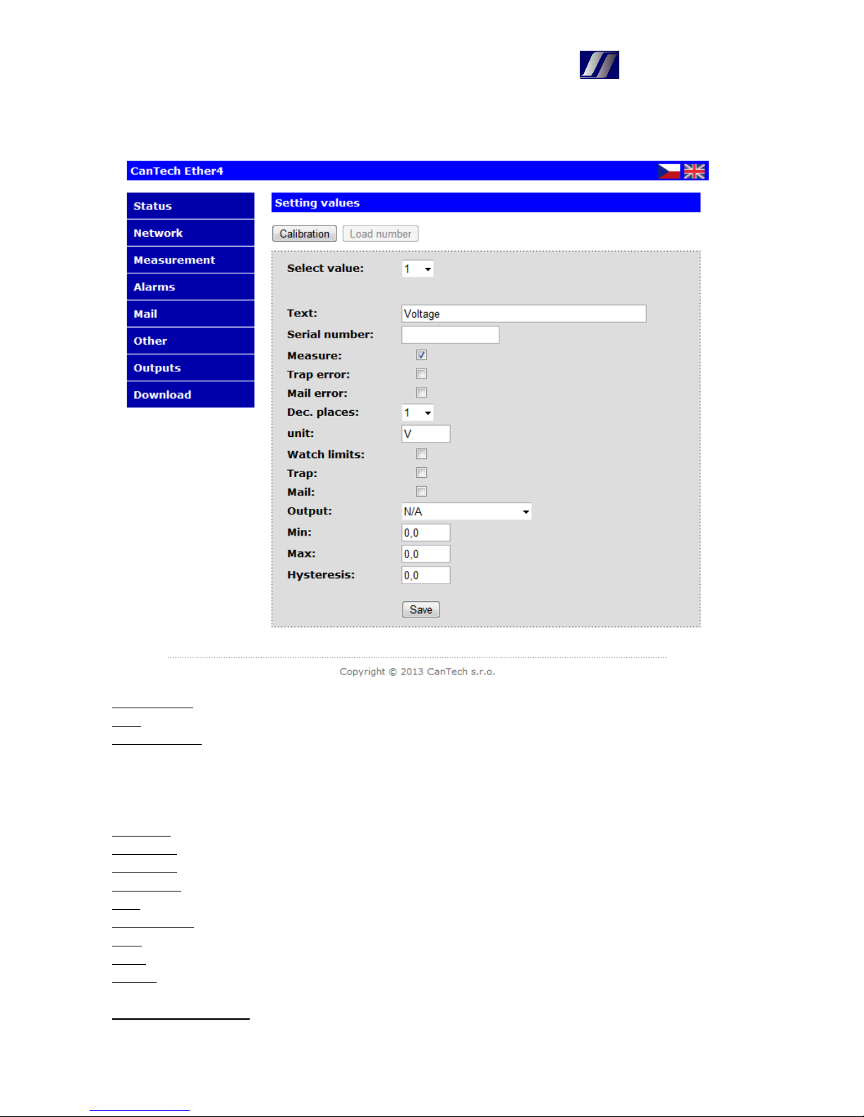
2.3 Measurement settings
Select value : select the value with which to work
Text : description of value – maximum 24 symbols
Serial number : number of the thermometer
- if it is used only one thermometer, a value is empty
- when using multiple thermometers, each must have its own address. The number can be entered
manually or provided that, they are connected gradually (only one), number can be loaded using
the button „Load number“
Measure : determines if a value is in a given position measure
Trap error : fail measurement trap is sent
Mail error : fail measurements are sending mail
Dec.places : how many decimal places the value is displayed
Unit : unit of display values
Watch limits : it determines whether to watch, if the value in the specified limits
Trap : sends the trap when limits are exceeded
Mail : mail will be sent when limits are exceeded
Output : determines the output, that is activated when limits are exceeded, INV behind the name
indicates that the output will be negated
Min, Max, Hysteresis
: settings of watched limits
Page 7
CanTech
7
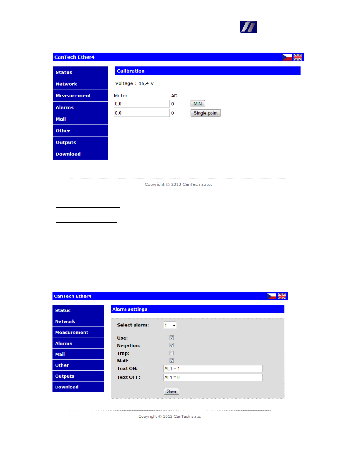
2.4 Calibration
Calibration can be performed either single-point or two-point:
- Single-point calibration – value at MIN remains 0,0 and at button single-point to enter the
current value and presses the button Single-point.
- Two-point calibration – sets the minimum value and this is entered at MIN and presses MIN.
Then set the maximum value and this is entered at Two-point and presses Two-point.
At the top left you can see the measured value
Note: The calibration constants are not stored after calibration to EEPROM memory – when you
turn off or change value on the card Measurement are read original. For save the constants is
necessary to return on card Measurement and press Save.
2.5 Alarm settings
Page 8
CanTech
8
Select alarm : select the alarm, with which to work
Use : if the alarm is to be used
Negation : checked – alarm is, when the contact is closed
unchecked – alarm is, when the contact is open
Trap : sends the trap
Mail : sends the mail
Text ON : text of presence of alarm
Text OFF : text of cancel the alarm
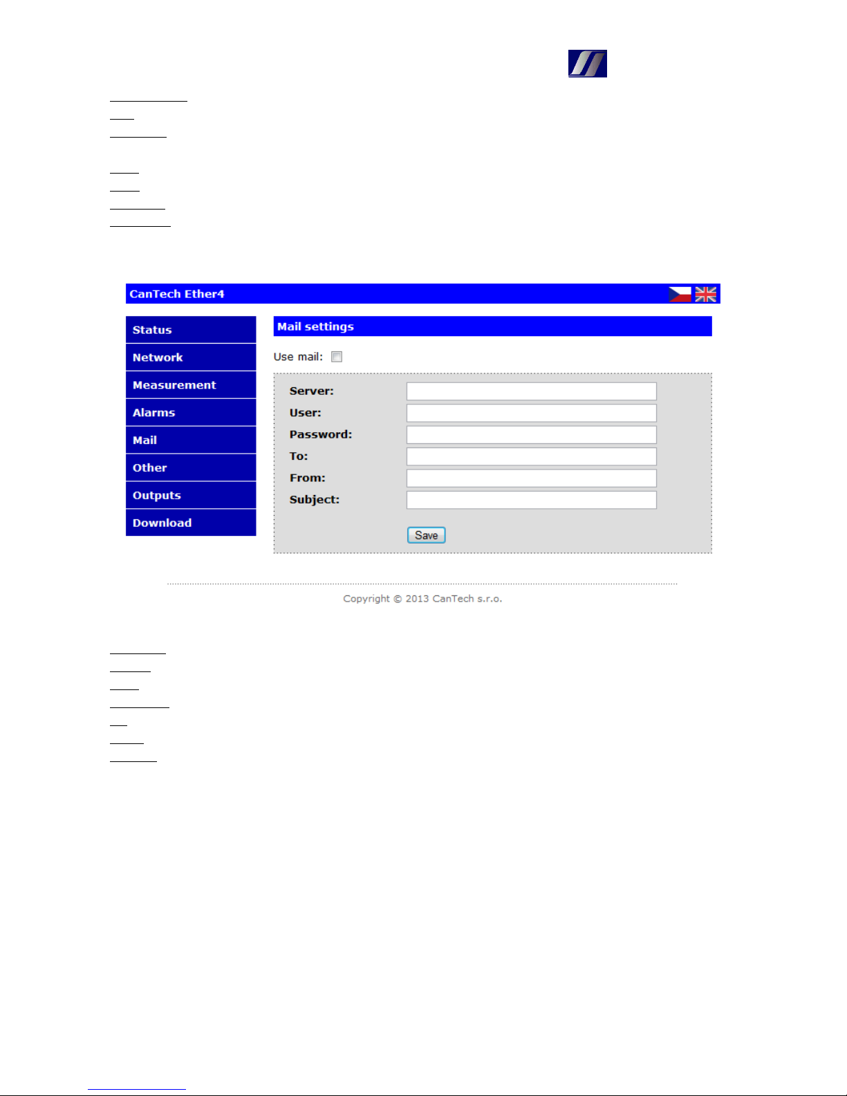
2.6 Email settings
Use mail : if they are to be sent emails – global ON or OFF
Server : SMTP server (max. 29 characters)
User : login for secure servers (max. 29 characters)
Password : login for secure servers (max. 14 characters)
To : to whom should be sent email, multiple recipients are separated by “,“ (max. 59 characters)
From : from whom (max. 19 characters)
Subject : subject of the report (max. 29 characters)
Page 9
CanTech
9
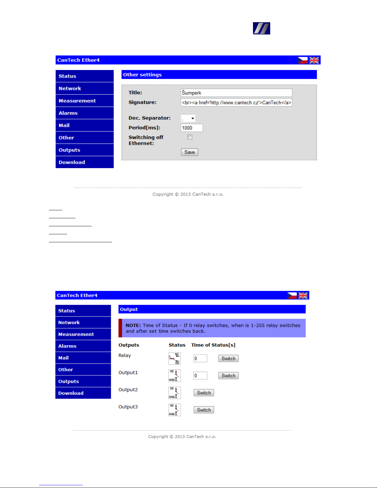
2.7 Other settings
Title : text displayed in the page header
Signature : text at the end of the window Status
Dec. Separator. : decimal separator
Period : period for refresh site Status in milliseconds. If 0, then the refresh does not
Switching off Ethernet : if checked and fulfilled condition, that the first output is controlled by
exceeding the limits, then, when it exceeds the minimum and the output switch, disconnect the
Ethernet, thereby substantially reduced consumption of device. It has using in applications backed
from batteries
2.8 Output
Page 10

CanTech
10
Time of status : determines the lenght of the switching relay (if I need to restart the switch, on
which hangs Ether4). If 0, the relay switches permanently.
- mark for the internal relay – displays the status of auxiliary relay contacts
- mark for the transistor output– displays the status of signal to the transistor base
2.9 XML
Analog values and alarm states are provided through status.xml
Value<0 – 15> – analog values
alarm – status of the inputs
salarm – which alarms are used
error – measurement fault
valarm – alarm of limits exceeding
measure – which values are measured
calarm – status of the user alarms
cmeze – limits of user alarms
cmod – mode for user alarms
tidx – index of the measured thermometer
Output states are in rele.xml
period<0 - 1> - if the relay was switched with set time of switching, this value determines the time
to switch back
status<0 - 5> - output status
type<0 - 5> - determines the type of output
- 0 … output is not connected
- 1,2 … relay is on output
- 3-8 … transistor is on output
Status of the inputs in the form of text are in texta.xml
talr<0 - 7> - input status
2.10 Reset the device
Using the site /config/tinit.htm can reset the device or putting in default settings
Page 11
CanTech
11
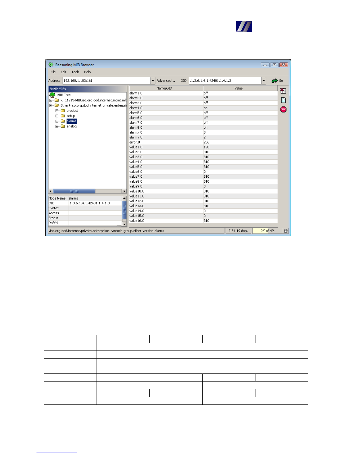
3. SNMP protocol
MIB file (Ether4.mib) is stored in the Ethernet card and is available in Download section.
Note: The analog values are converted to an integer value, by multiple according to number of
decimal places.
4. Modbus TCP
Card communicates with Modbus protocol on port 502. The measured values are converted to an
integer value according to the number of decimal places and stored in registers starting at address
30001 in 32bit form.
Register Byte3 Byte2 Byte1 Byte0
(1) Value0
(2) Value1
…
(16) Value15
(17) Alarms of values Used alarms Alarms
(18) Failures of measurement Measured values
(19) Period1 Period0 Used outputs Output states
(20) State of user alarms Used user alarms
Page 12
CanTech
12
5. Program for setting – Eth4_setting.exe
5.1 Introduction window and description of menu
Menu:
File
Open – load the settings file
Save – saves the settings to a file
Save as – saves the settings to a new file
Setting
Load – loads the entire setting of Ethernet card
Save – saves entire setting to the Ethernet card
Note: <Load> <Save> in individual windows works only with partial settings
Display – opens the windows for setting
Page 13
CanTech
13
Login(Logout) – used to log on to enable the save settings
IP address – IP address of card you want to set
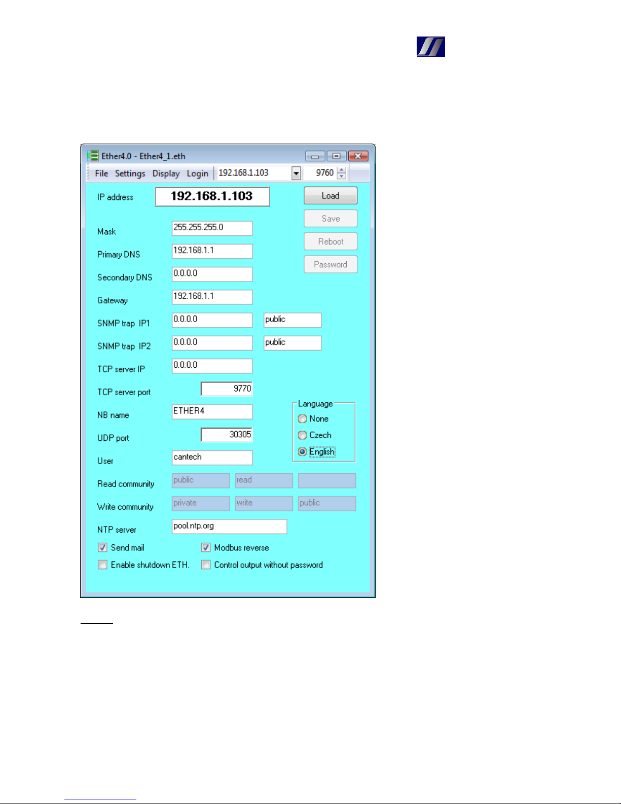
In this window you can set the parameters of network. In addition you can enter:
SNMP trap IP(1,2) – target server for a trap and community
NB name – name card
UDP port – port for communication over UDP
User – username for administrator access
(Read, Write) community – community of SNMP protocol
NTP server - time server
Send mail – globally enable of sending mails
Enable shutdown ETH. – see. network settings using the HTTP
Modbus reverse – values are stored in registers in the reverse order of bytes
Reboot – resets the card to update the network parameters
Pasword - save the new password
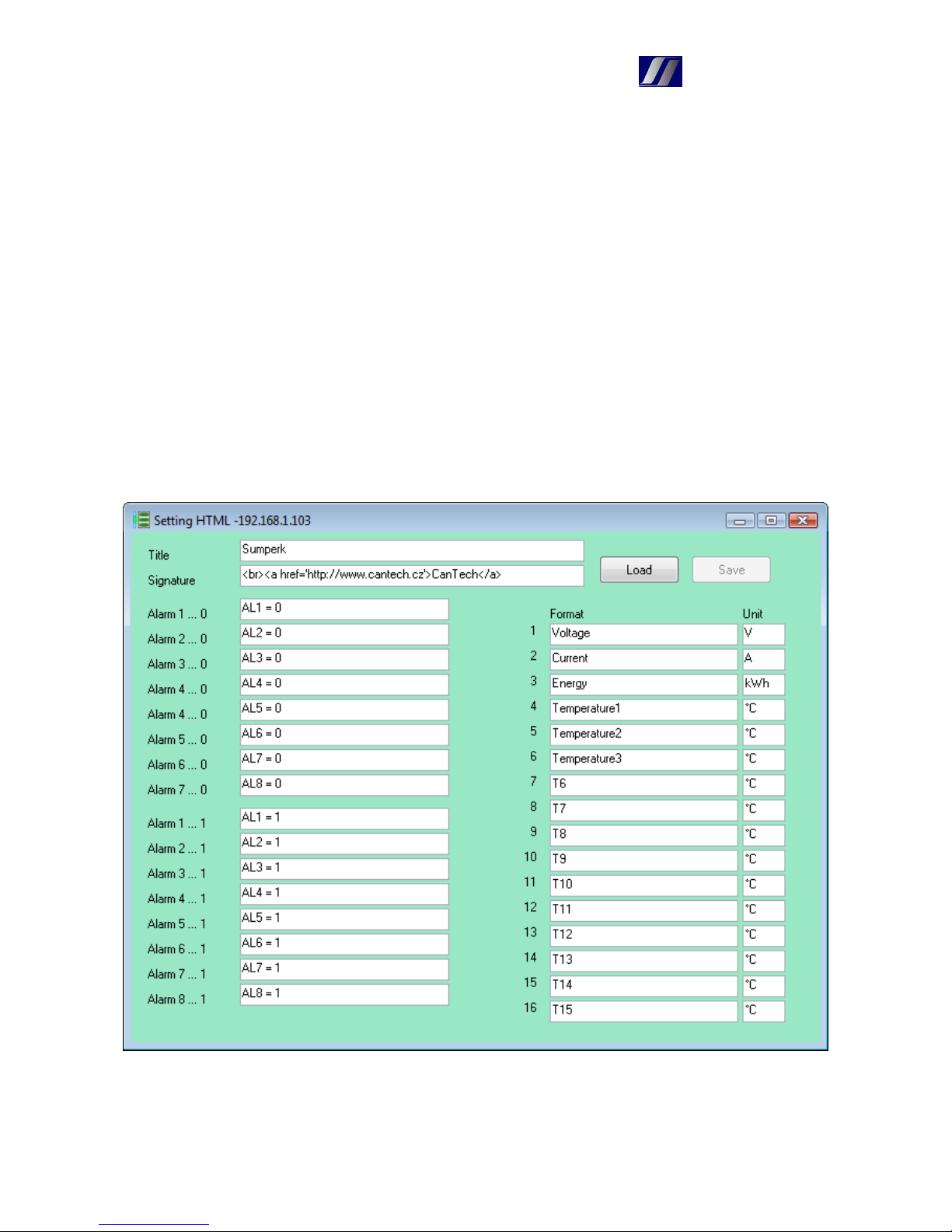
5.2 HTML – setting texts
Using this window you can set texts of headers, alarms and values as through HTML.
Page 14
CanTech
14
5.3 Config. – measurement setup
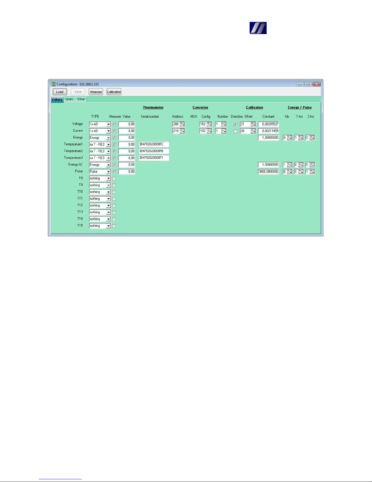
Sets the AD converters and their calibration, setings thermometers, power consumption and alarm
inputs. AD converters can be used only for the first eight values (default is fitted only measuring
voltage converter).
Type - 1xAD – simple AD converter
2xAD 1. – double converter 1. input
2xAD 2. - double converter 2. input
1xT - RE3 – one thermometer on port RE3 (no need to enter the seriál number)
1xT - RC2 – one thermometer on port RC2 (at this version is not used)
nxT - RE3 – multiple thermometers on port RE3 (must enter the seriál number)
Energy – calculates the energy
Pulse – work with a delay between pulses on the inputs 1,2
Nothing – value is not used
Measure – if the value should be measured
Value – display of the measurement result after the tap of a button Measure
Serial number – number of thermometer – right mouse button to load number (at this point must
be connected just one thermometer)
Address – I2C converter address
MUX – port of I2C multiplexer
Config – configuration constant of AD converter
Number – number of measurements for averaging values
Direction – indicates, that the measured variable takes only positive values – to the measurement
around zero does not appear –0,0
Offset – displacement of converter in zero (in LSB)
Constant – conversion constant of value
Idx – index of energy or pulse (0,1)
1.hrs – if the type Energy
0..7 – 1. value of multiple
8 – energy is calculated based on arrival pulse on input
- if the type Pulse
Page 15
CanTech
15
0..1 – number of binary input which generates a pulse
2.hrs – if the type Energy
0..7 – 2.value of multiple
if the type Pulse
0 – measure time between pulses
1 – measure performance
Description of the calculation of energy:
DC energy(consumption)
Assigned Type=Energy, 1.hr=(0..7), 2.hrs=(0..7)
Because Ether4 has no clock circuit, it is based on crystal frequency of processor (its accuracy
indicates the accuracy of the calculation of energy). About every 1,6s (exactly 3*2^26/(125*10^6) )
timer overflow occurs and at this time is calculated energy.
< Energy > = <Energy> + <1.hr> * <2.hr> / 2235.174
This value is roughly every minute saved in EEPROM (set minute, because memory has a limited
number of entries).
To view the energy is used calculation
<Value> = <Energy> * <Constant>
This allows display energy in Wh (Constant = 1.0), or in kWh (Constant = 0.001)
Consumption of connected meter with SO output
Assigned: Type=Energy, 1.hr=8, 2.hr=(0..1)
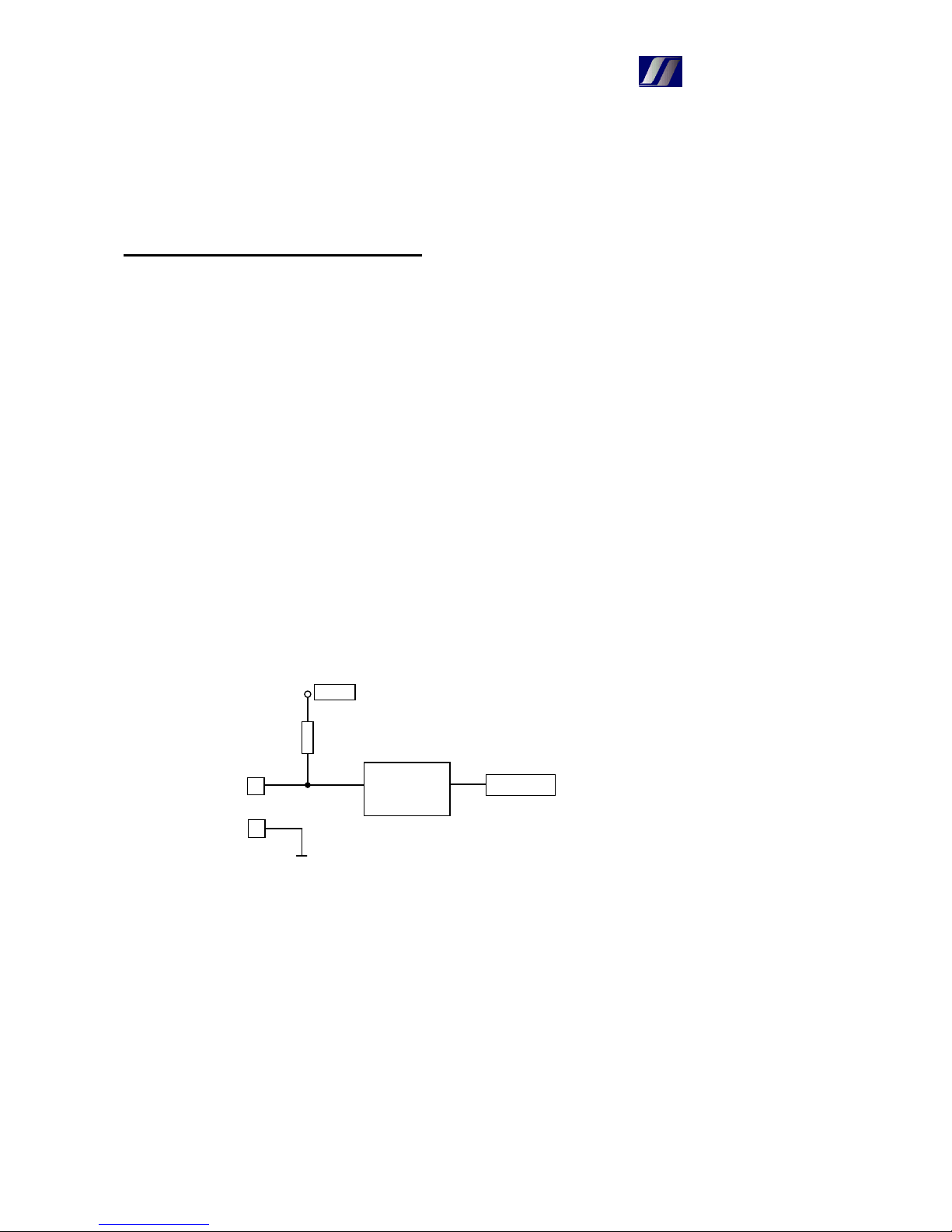
Note: because the binary inputs are connected as follows
Connected meter must “master“ level voltage 3,3V. We tested measurement the consumption with
electricity meter Maneler 9901.
Consumption is calculated every 1,6s as follows
< Consumption> = < Consumption > + <Number of pulses>
and the displayed value is
< Consumption > = < Consumption > * <Constant>
where the constant is determined by the type of meter.
IN+
Protection
IN-
Processor
+3,3V
Page 16
CanTech
16
Work with pulses:
The time between pulses
Assigned Type=Pulse, 1.hr=(0..1), 2.hrs=0
Pulse lenght is calculated as follows
<Value> = <n> / <Constant>
where <n> is the number of CPU ticks ( 1s = 125*10^6/(3*2^8) ticks )
Constant = 40690,104 specifies delay in seconds
Measurement of immediate consumption
Assigned Type=Pulse, 1.hr=(0..1), 2.hrs=1
Immediate consumption is calculated as follows
<Value> = <Constant> * 40690,104 / <n>
Note: <n> may take up maximum 2^32, which corresponding about 29 hours
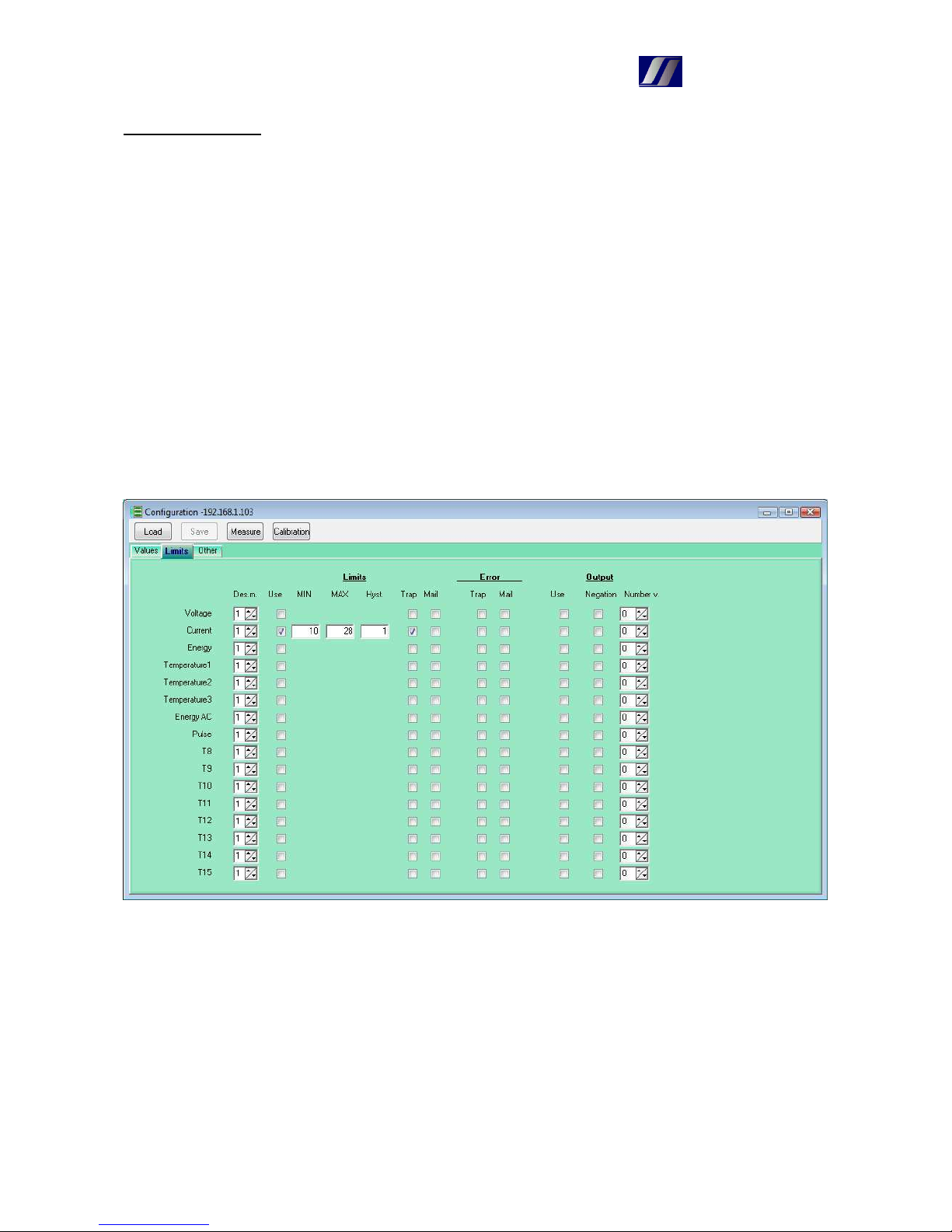
Des.m. – number of decimal places
Use – use the control limits
MIN, MAX, Hyst – parameters of limits
Trap, Mail – when exceeding the limits is sent trap, mail
Error – Trap, Mail - when fail is sent trap, mail
Output – Use – when exceeding the limits the output is activated
Negation – output operates in reverse
Number v. – which output is activated
Page 17
CanTech
17
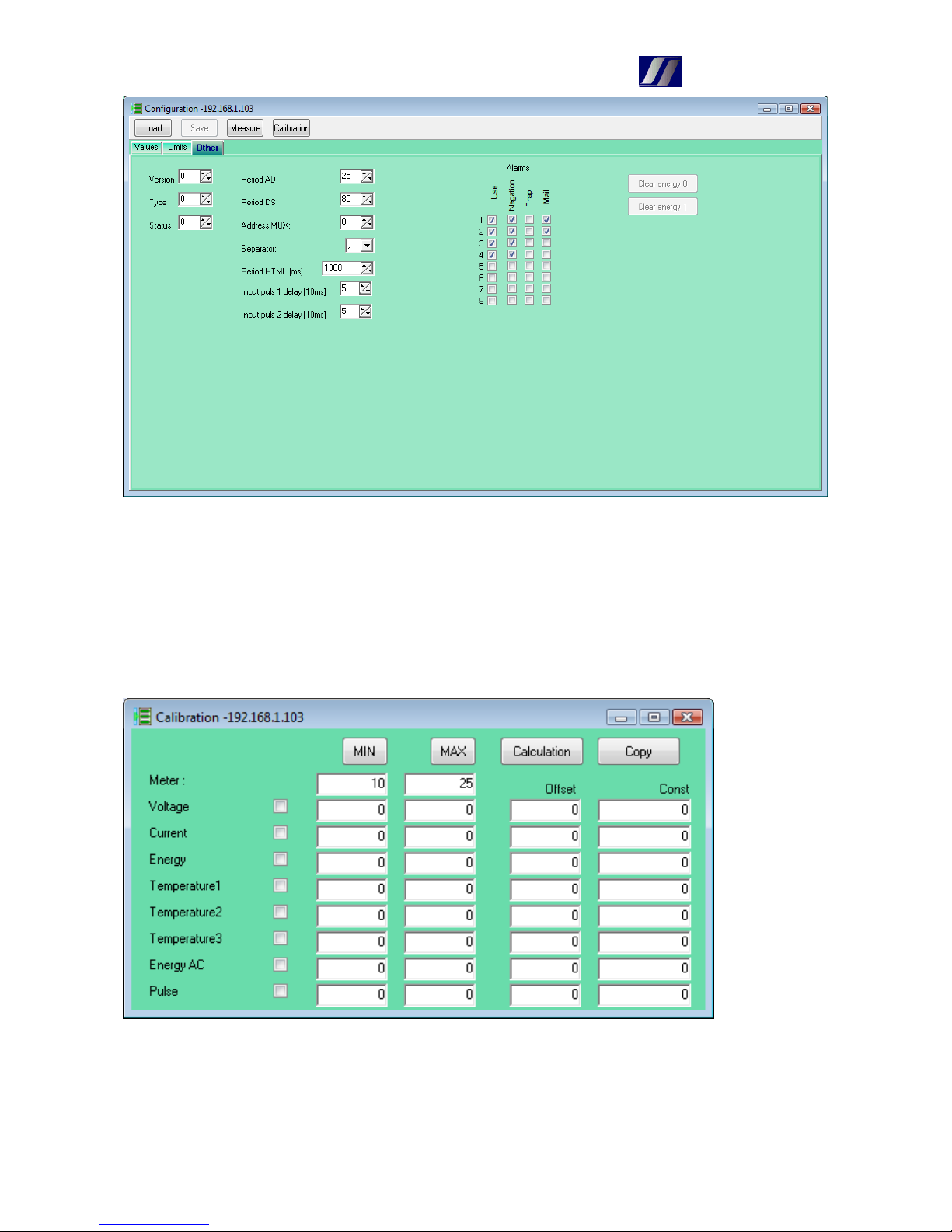
Version, Type, Status – not used yet
Period AD – time in 10ms between reading AD converters
Period DS – time in 10ms between reading thermometers
Address MUX – address I2C multiplexer
Separator – character of separator of decimal places
Period HTML – period of update HTML page Status
Input pulse 1(2) delay – minimum length SO pulse at 10ms
Calibration procedure:
- selection of value, with which I want to work
- set the minimum value
- enter it on line Meter
- tap on MIN
Page 18
CanTech
18
- perform the same with the maximum value
- Calculation – calculate the value of offset and constant
- Copy – calculated values are copied into the corresponding fields on the card Values
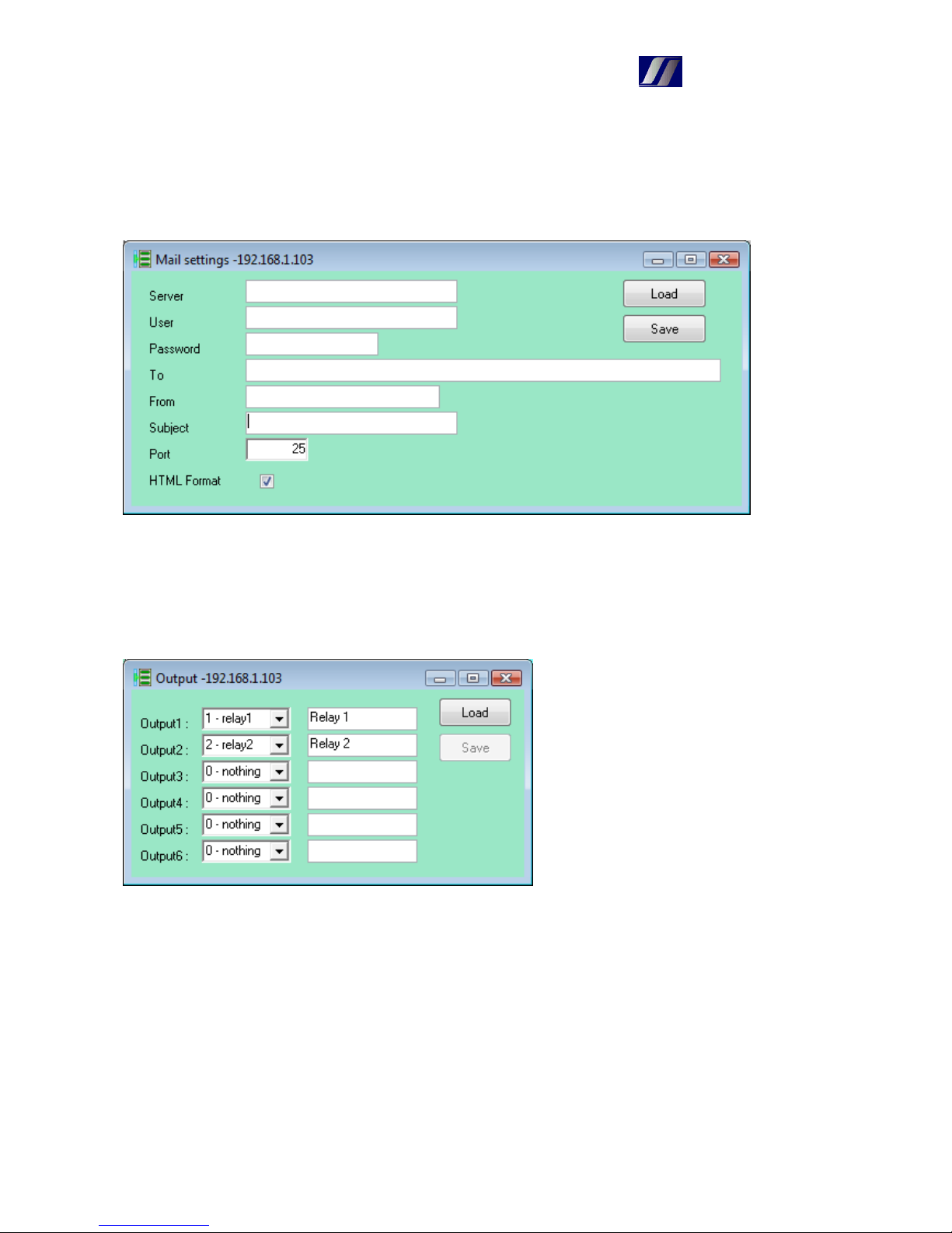
5.4 Mail – mail settings
Same as in HTML.
Format HTML : in the mail are used HTML Tags
5.5 Output – output settings
Used to assign physical outputs to logic. It is factory set and user should only change the
description of the output.
Page 19
CanTech
19
5.6 Custom alarms – set custom alarms
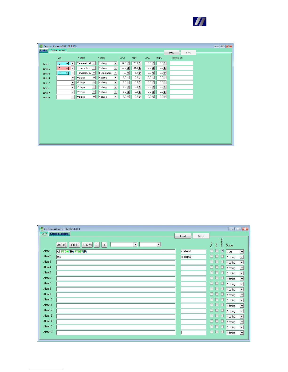
Limits are used to monitor values like limits on measurement. Use for setting thermostat, that enter
into user alarms.
Type : select the type of thermostat
Value1 : input value to the thermostat
Value2 : if selected, the difference of Value1-Value2 enters to the thermostat
Low1, High1 : limits of the thermostat for mod=0
Low2, High2 : limits of the thermostat for mod=1
Ether4 operates in mode 0. Over TCP can be changed mod to 1, so without having to reconfigure
the limits of thermostats, You can change the level of monitoring limits only with single
command.
Page 20
CanTech
20
Each user alarm consists of logical operations between individual operands. Using the timer
function, signals can be delayed (it used max. 8 timers). Based on the evaluation of the user alarm
sends a trap, mail or switches associated output. Alarm is evaluated from left to right and
parentheses indicate priority.
As an operand can be used:
- Alarm … status of the binary input
- Value alarm … limits of measured values
- Error … measurement error
- Limits … custom alarm limits
- Custom alarm … another user alarm
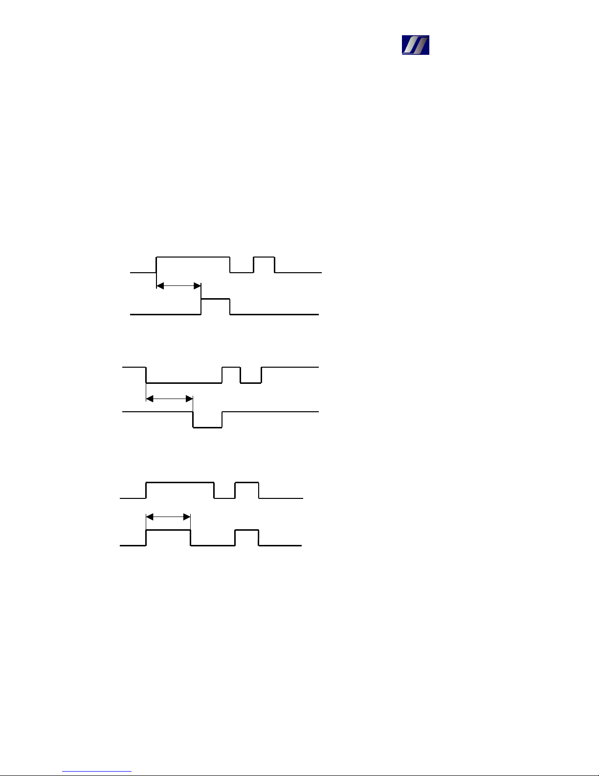
Timer function are (dT – duration in seconds):
- FTON(dT) … delay of rising edge
- FTOFF(dT) … delay of falling edge
- FPULS(dT) … pulse after rising edge
dT
input
output
dT
input
output
dT
input
output
Page 21

CanTech
21
5.7 Discoverer – search device in network
Finds all Ether4 in network and displays their IP address , NB name and MAC address.
Page 22
CanTech
22
6. Program Ether4.exe
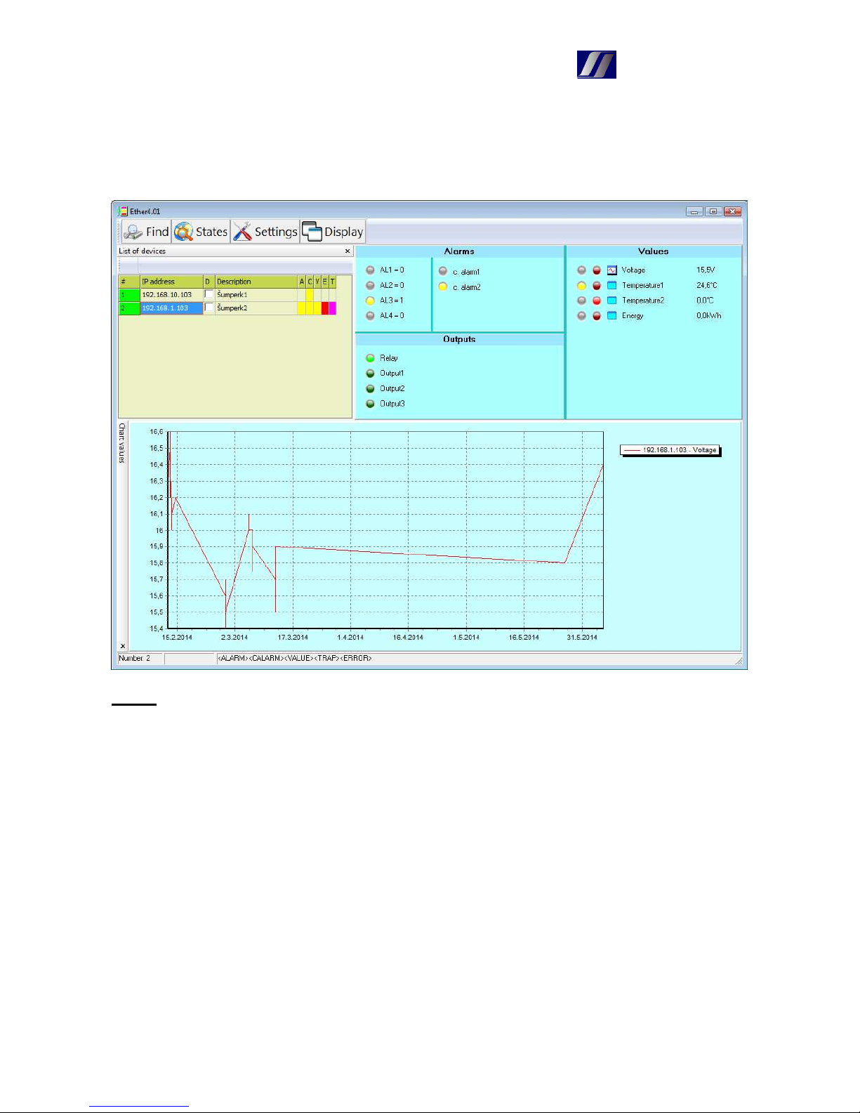
Program used to monitor one or more devices Ether4 in the network. Displays the status of inputs,
outputs, user alarms and measured values. Status changes can be saved to a log file. Measured
values can be saved to files and plot their graph.
Menu:
Find – find the device in the network and add it to the list
States – reads the status of all devices from the list
Settings:
Delay of query – delay in seconds when repeated detecting state
Capture traps – if they are to capture incoming traps
Read status in trap – if the update status of the device when receiving a trap
Write Log – events stored in the file Ether4.log
Show window in trap – when receiving a trap window opens
View the message at a trap – if the program runs minimized, bubble appears
at a icon of program
Start normally – program starts as the normal application
Start minimized – when you start the program adds an icon to SystemTray
Display – here can show and hide individual toolbars and change their
arrangement
Appearance of menu can be changed by clicking the right mouse button.
Page 23
CanTech
23
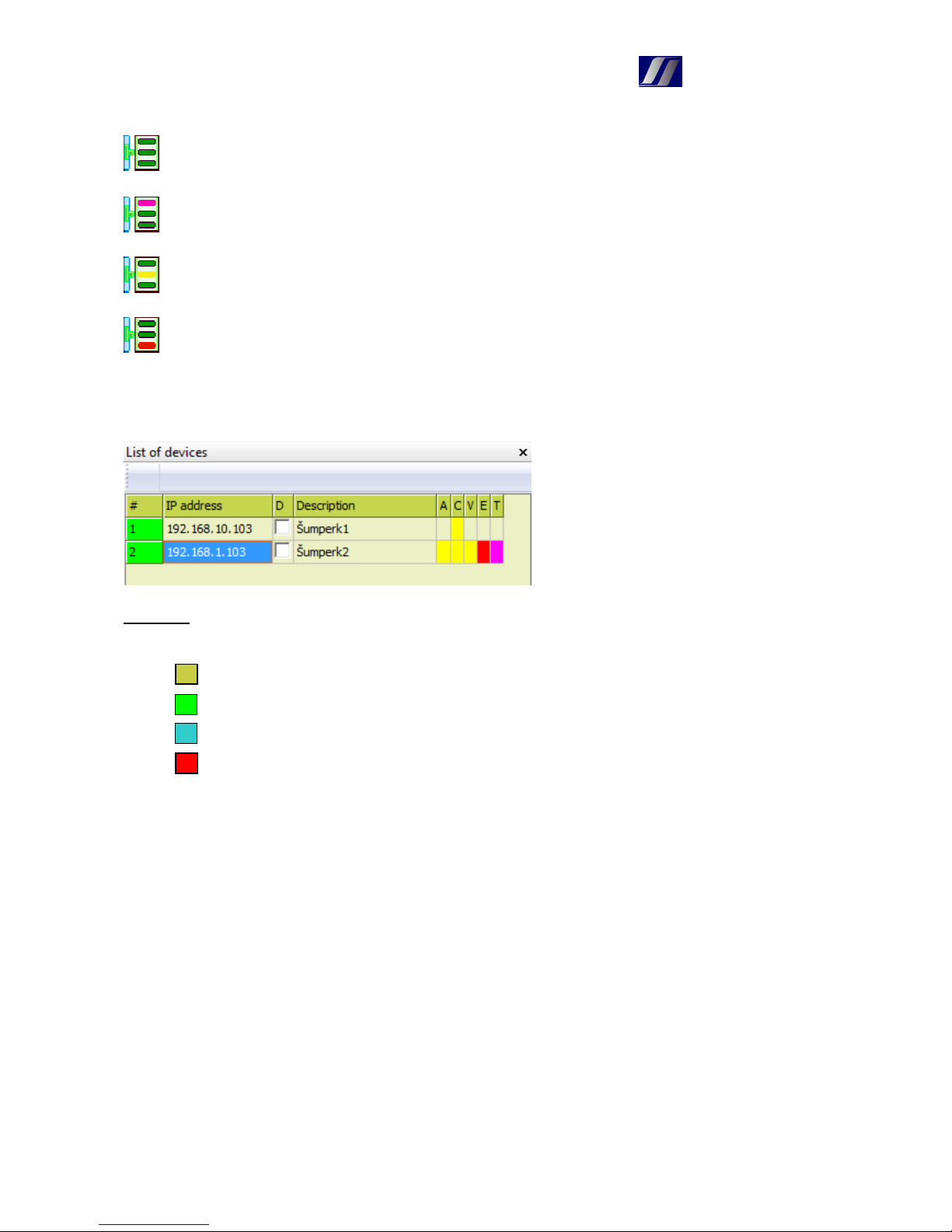
Device states are also displayed in the icon of the program:
All devices are within normal
Was captured the trap
Somewhere there is alarm
Appeared measurement fault or communication
6.1 Panel of Device list
Column:
# - serial number, color of field specifies the communication status
still did not communicate
communication was successful
just communicate
communication error
IP address – device address
D – if is set the delay of query in menu, this field to select the devices, that we want to
monitor
Description – description of the device
A – alarm
C – user alarm
V – exceeding the limits of the measured values
E – measurement fault
T – came trap – after click on the line this indication will disappear
Right-clicking on a line of list appears menu:
Status – updates the status of the selected device
Texts – updating descriptions
Up – line moves up one position
Down – line moves down one position
Insert – inserts the line
Delete – deletes the line
Page 24
CanTech
24
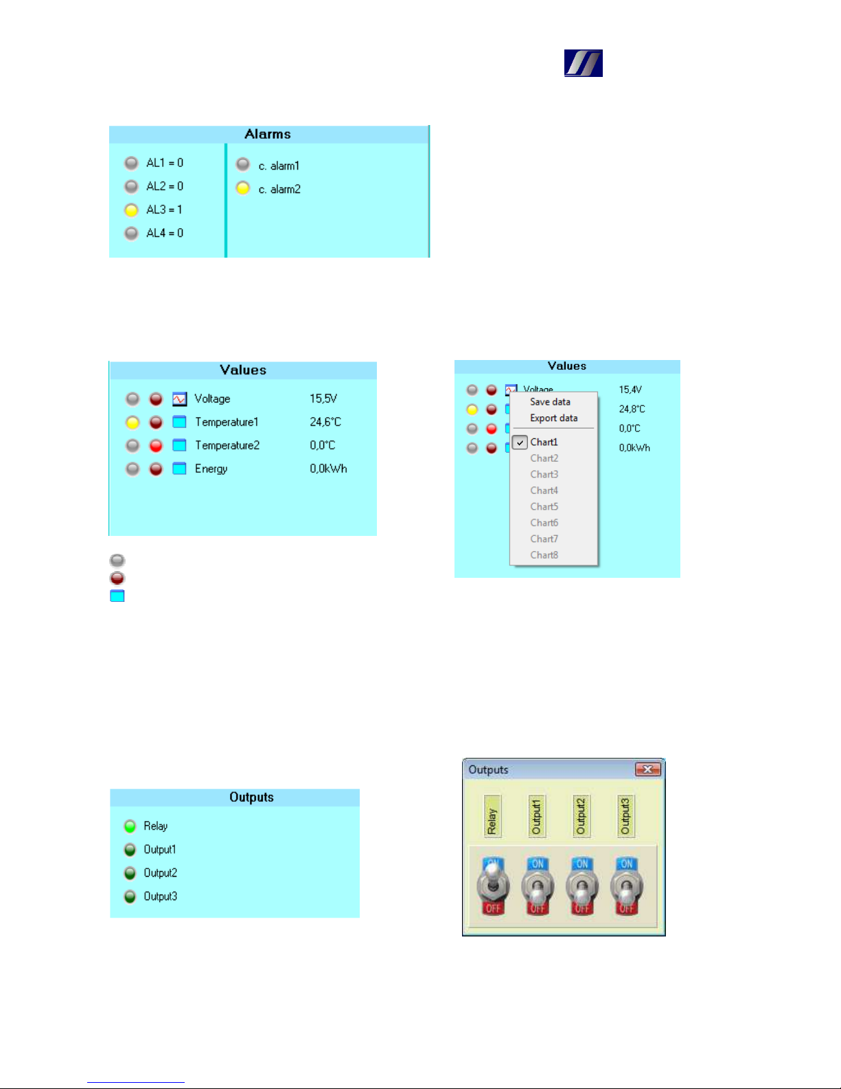
6.2 Alarms panel
In left column are shown the status of digital
inputs, the right displays the users alarm. If
there is no defined user alarm, so does not
appear
The green LED in left upper corner appears
when List of devices is hidden and displays
the communication status. Double click on it
to updates the status.
6.3 Values panel
- State of limit value
- Measurement fault
- For working with data – right click menu appears
Save data – at each reading of state the values are saved into file
Export data – data is exported to Excel
Chart <1-8> - values are displayed in the chart (only when saving to a file)
Note: File with data is in Application directory and its name consist of IP address and number of
value (from zero). If you want to start a new measurement, this file must be deleted or renamed.
6.4 Outputs panel
Displays the status of the outputs. After clicking the left mouse button on the green LED can change
this situation.
Page 25
CanTech
25
After clicking on the switch, the output switches. Before switching will ask for a name and
password. Login data are stored and the second time to them without asking.
7. Upgrade firmware
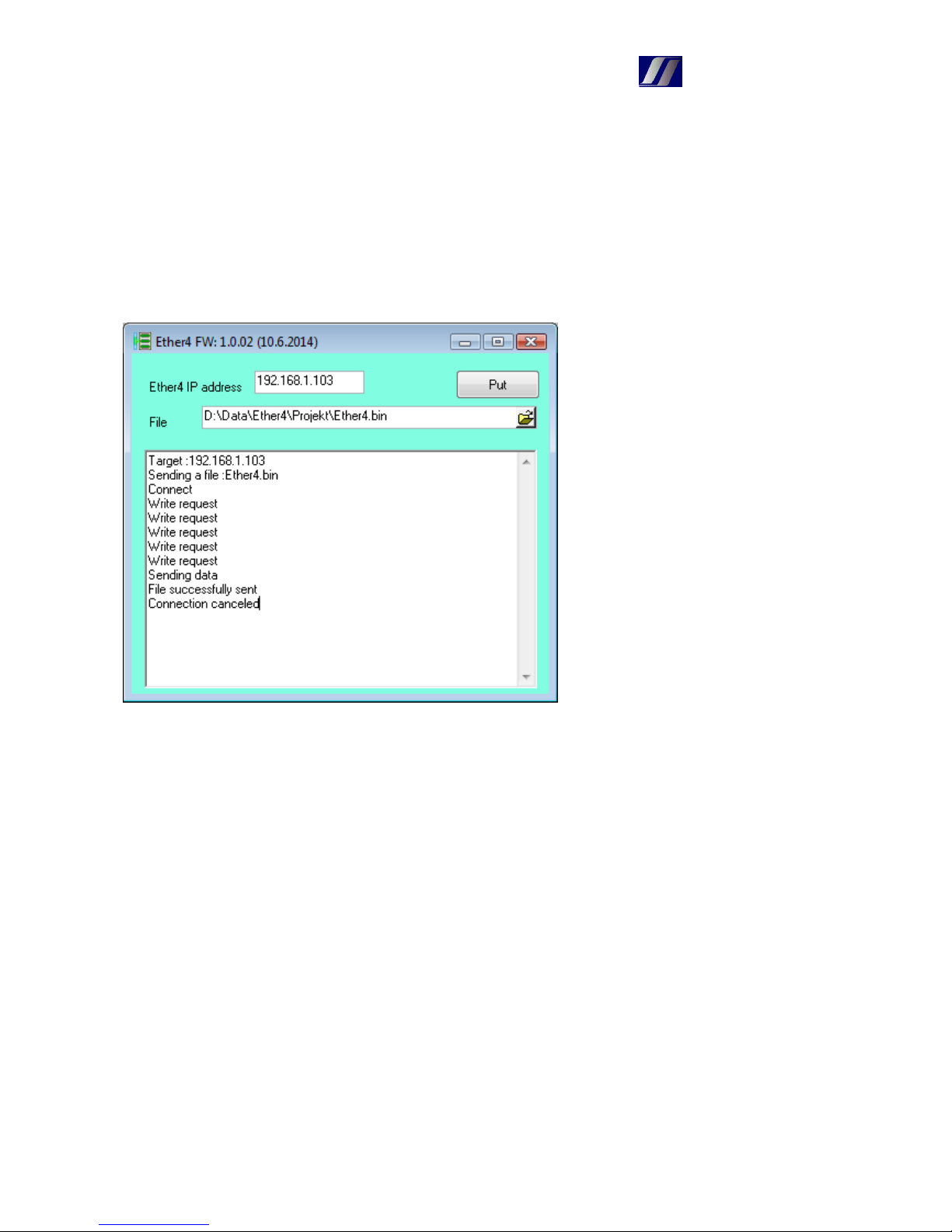
Program Ether4_FW.exe used to store the new firmware to Ether4.
IP adresa Ether4 – IP address of card
File – to select the file with the new FW
Send – upgrades the new FW – communication status is printed in window
After the Send command performs the following:
- Card restarts
- Introduce a bootloader with the current IP address and MAC address
- Introduce the new FW
- The card will reboot and after about 4 seconds starts new program
In carrying out the upgrade should not be broken the connection or power card. If this happens, the
card is broken – it only runs bootloader. When communication is interrupted, procedure may be
performed again. If power is interrupted, bootloader does not use set IP address, but the deafult
(192.168.1.103) and the upgrade must be performed with this IP address.
Page 26
CanTech
26
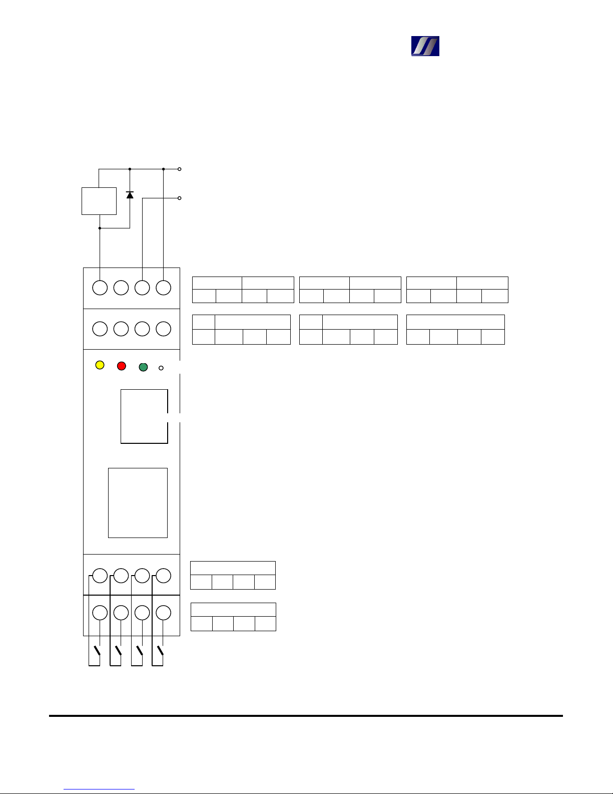
8. Connection
OD DC(9-60V)
3 2
- +
OD DC(9-60V)
6 5
- +
Relay2 DC(9-60V)
NC C
- +
R2 Relay1
NO NO NC C
OD Relay1
1 NO NC C
OD
4 3 2 1
Alarms+
IN4 IN3 IN2 IN1
Alarms-
IN4 IN3 IN2 IN1
CanTech s.r.o.
Potoční ul. č.p. 2173/40
787 01 Šumperk
Tel.
: +420 583 250 991, +420 583 250 995
Web : www.cantech.cz
E-mail : [email protected]
Example of connecting of external
relay via OD output
Error
Alarm
Reset
Operation
Ethernet
External
relay coil
Thermometers
OD
DC+
DC-
Firma CanTech si vyhrazuje právo pro případné změny. Prosím, kontaktujte obchodního zástupce firmy CanTech pro další informace.
 Loading...