

Cansec SMARTLOCK Series, SmartLock Pro Plus Series, SmartLock Pro series Installation Manual
Page 1

SmartLock® Controller
INSTALLATION MANUAL
November 2018
Page 2

Table of Contents
INTRODUCTION ....................................................................................................................... 3
Diodes ............................................................................................................................ 4
Terminal Strips and Cable .............................................................................................. 5
SPECIFICATIONS ..................................................................................................................... 6
SMARTLOCK CONTROLLER LAYOUT ................................................................................... 8
LED Indicators ................................................................................................................ 9
Mounting ........................................................................................................................ 9
RS-485 COMMUNICATIONS WIRING .....................................................................................10
CLAUSB Communications Device .................................................................................10
CANLAN Network Communications Device ...................................................................10
AIR-485 Communications Device ..................................................................................12
READER WIRING ....................................................................................................................13
Wiegand Reader ...........................................................................................................13
iButton® Reader .............................................................................................................14
LOCK OUTPUT RELAY WIRING .............................................................................................15
DC Electric Strikes.........................................................................................................15
DC MagLocks ................................................................................................................16
AC MagLocks and AC Electric Strikes ...........................................................................17
INPUT WIRING .........................................................................................................................18
Exit Button, Handicap Button, Door Contact ................................................................ ..18
OUTPUT WIRING .....................................................................................................................19
Door Operator, Forced Entry, Door-Held-Open .............................................................19
DIP SWITCH .............................................................................................................................20
Function ........................................................................................................................20
Location .........................................................................................................................20
Erase Controller Memory, Diagnostics...........................................................................21
Door Contact Bypass Switch Setting .............................................................................22
CONTROLLER ADDRESS TABLE ..........................................................................................23
APPENDIX ...............................................................................................................................25
CLA50 Communications Wiring .....................................................................................25
CLAUSB2 Communications Wiring ................................................................................25
SmartLock® Controller Page 2 of 26
Installation Manual Nov 2018 • Rev. 3.2
Page 3

CAUTION: EMERGENCY LOCKDOWN
Emergency lockdown functions must operate totally independent of the access
control system and must not rely on operation of card readers, access control panels,
communications networks, communications devices or host software. Cansec
accepts no responsibility for direct or consequential damages resulting from the
failure of emergency lockdown functions which are dependant in any way on the
operation of card readers, access control panels, communications networks,
communications devices or host software.
CA-PS123A Specifications Notice:
When using a pluggable 16 VAC standard 40 VA transformer:
Maximum Continuous Current (no battery attached): 2 amps for 12 VDC on
the Output.
Maximum Continuous Current (battery attached): 1.5 amps for 12 VDC on
the Output (battery will be charging when needed).
Using a wire in 16 VAC standard 75 VA transformer:
Maximum Continuous Current (no battery attached): 2.5 amps for 12 VDC
on the Output.
Maximum Continuous Current (battery attached): 2.0 amps for 12 VDC on
the Output (battery will be charging when needed).
Surge currents need to be taken into account. High current devices like
electric strikes and magnetic locks have surge currents which are usually
double the running current.
The CA-PS123A’s DC output is fused at 2.5 amps.
An electrician is not required for installation of this supply.
SmartLock® Controller Page 3 of 26
Installation Manual Nov 2018 • Rev. 3.2
Page 4

Introduction
IMPORTANT: In some jurisdictions, the use of a UL approved
power supply and connection to the fire alarm system for
emergency release may be required. Installers should contact the
local authority having jurisdiction to verify the specific
requirements. Also, a building permit may be required in some
jurisdictions for the installation of maglocks.
The SmartLock® access control panel is a single door controller with inputs
for both entry and exit readers. Readers and card formats supported include
Cansec 37, 26 and 35-bit Corporate 1000 Wiegand formats, and Cansec
iButton® credentials. Other card formats can be accommodated with the use
of Cansec Protocol Converters (contact Cansec for further information).
SmartLock controllers with Pro Plus firmware (SLPPx.x) only work with
SmartLock Pro Plus software.
SmartLock controllers with Pro firmware (SLPTx.x) only work with
SmartLock Pro, SmartLock Managed Access and SmartLock Surf software.
The SmartLock control panel stores all cardholder data in non-volatile
memory to ensure continued operation and security in the event that
communications are lost to the host PC. Up to two control panels are easily
mounted in a SmartLock enclosure along with a Cansec 12 VDC power
supply and a back-up battery.
DIODES
Diodes are required for inductive loads such as electric strikes/locks. Failure
to use appropriate diodes will void the control panel warranty.
SmartLock® Controller Page 4 of 26
Installation Manual Nov 2018 • Rev. 3.2
Page 5
TERMINAL STRIPS AND CABLE
Use Appropriate Cable Thickness
For optimal performance and communication, the terminal strips on the
SmartLock control panel are designed to be used with 26 – 18 American
Wire Gauge (AWG) stranded, overall-shielded, twisted-pair cable. This is
equivalent to Belden 88761 or similar cable.
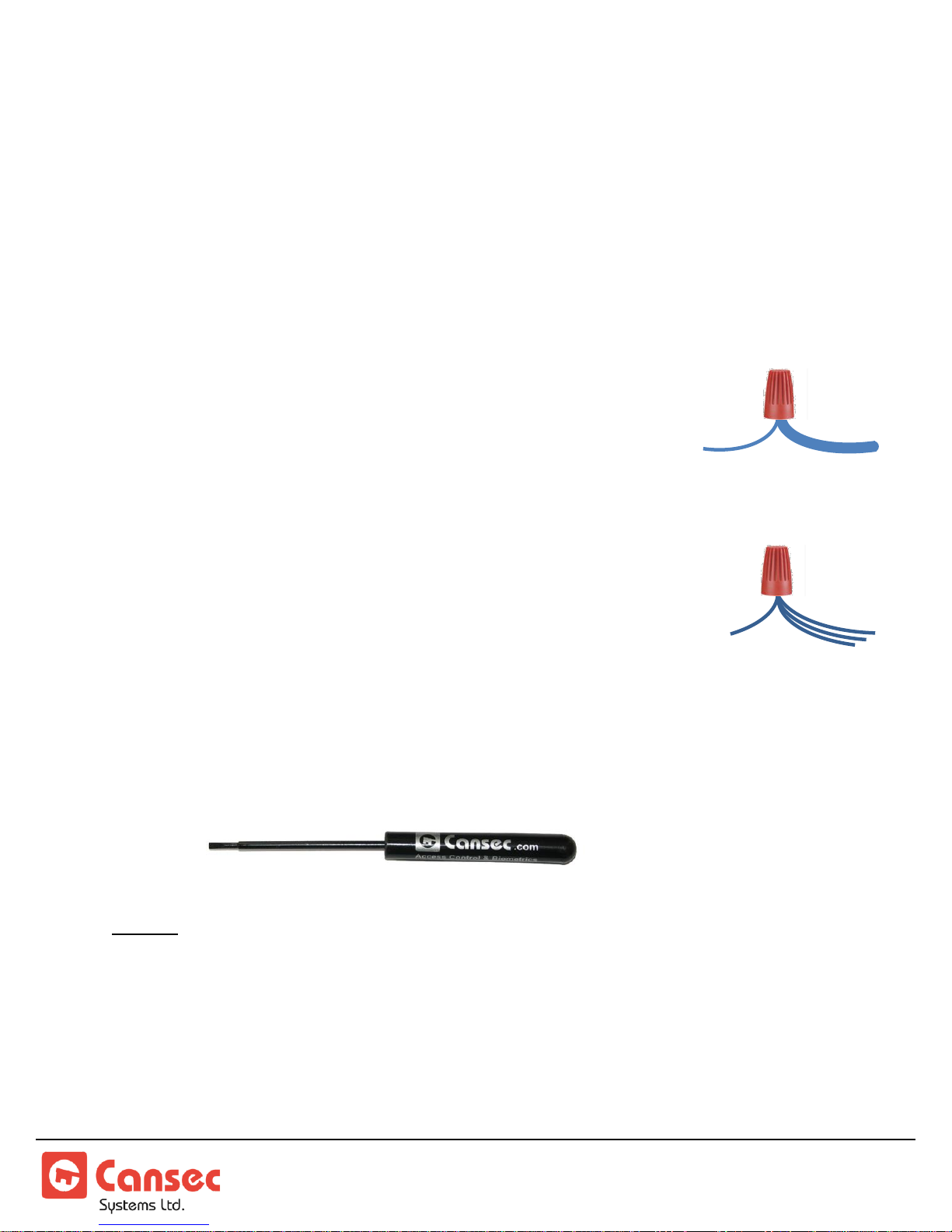
Use MARR Connectors
If you are bringing in cable that is too large for the terminal
strip, use a MARR connector (wire nut, marrette, thimble
connector, cone connector). Splice the thicker cable to a cable
that is the appropriate thickness, and then run the thinner
cable to the terminal strip on the control panel.
Use Splices for Parallel Wiring
The terminal strips are designed to allow one cable per hole.
If you need to connect multiple cables in a single hole, use a
MARR connector (wire nut, marrette, thimble connector,
cone connector). Splice multiple cables to a single cable, and
then run the single cable to the terminal strip on the control
panel.
Complimentary Screwdriver
A standard Cansec screwdriver is included with every control
panel for use with terminal strips.
NOTE: Tech Support will only be provided where product installation guidelines
have been followed.
SmartLock® Controller Page 5 of 26
Installation Manual Nov 2018 • Rev. 3.2
Page 6

Specifications
IMPORTANT: In some jurisdictions, the use of a UL approved power supply
and connection to the fire alarm system for emergency release may be required.
Installers should contact the local authority having jurisdiction to verify the
specific requirements. Also, a building permit may be required in some
jurisdictions for the installation of magnetic locks.
Power Requirements
SmartLock
NOTE: When determining power supply current requirements, you must consider lock
and reader current draw if using the same supply for these devices.
NOTE: If a gate operator is being used in place of a lock then an external relay is
recommended between the controller and the gate operator. The relay must have a
diode installed to prevent “back EMF” from damaging the controller.
Communications Cable (multi-drop configuration)
®
Controller: .............................................. 12 VDC, 50 mA
RS-485 Cable: ................... 22 AWG, Stranded/Shielded, Twisted Pair
............................................................. 609 m (2000 ft) max total length
..................................................................... Belden 88761 or equivalent
On-Board Outputs
Lock Control: ................................... Form “C”, Rated @ 30 VDC, 1A
Door Operator: ................................. Form “C”, Rated @ 30 VDC, 1A
Forced/DHO Relays: ....................... Form “C”, Rated @ 30 VDC, 1A
On-Board Inputs
Exit Button: .................................................................... Normally Open
Door Contact: ............................................................... Normally Closed
Door Operator: ............................................................... Normally Open
...........................................................................................................................
SmartLock® Controller Page 6 of 26
Installation Manual Nov 2018 • Rev. 3.2
Page 7

Reader Cable
Wiegand Readers: .................... 6 conductor (twisted pair not required)
............................................................................ 22 AWG, overall shield
............................................................... 152 m (500 ft) max total length
iButton
®
Readers: ............................................................... 6 conductors
............................................................ 22 AWG, shielded or unshielded
................................................................... 15 m (50 ft) max total length
Dimensions & Weight
Controller Board: ............................................... 84 mm (l) x 65 mm (w)
....................................................................... [ 3 5/16” (l) x 2 9/16” (w) ]
SmartLock Cabinet:.................. 260 mm (l) x 216 mm (w) x 80 mm (h)
....................................................... [ 10 1/4” (l) x 8 1/2” (w) x 3 1/8” (h) ]
Weight: ...............................................................................2 kg (4.5 lbs)
Specifications subject to change without notice.
SmartLock® Controller Page 7 of 26
Installation Manual Nov 2018 • Rev. 3.2
Page 8
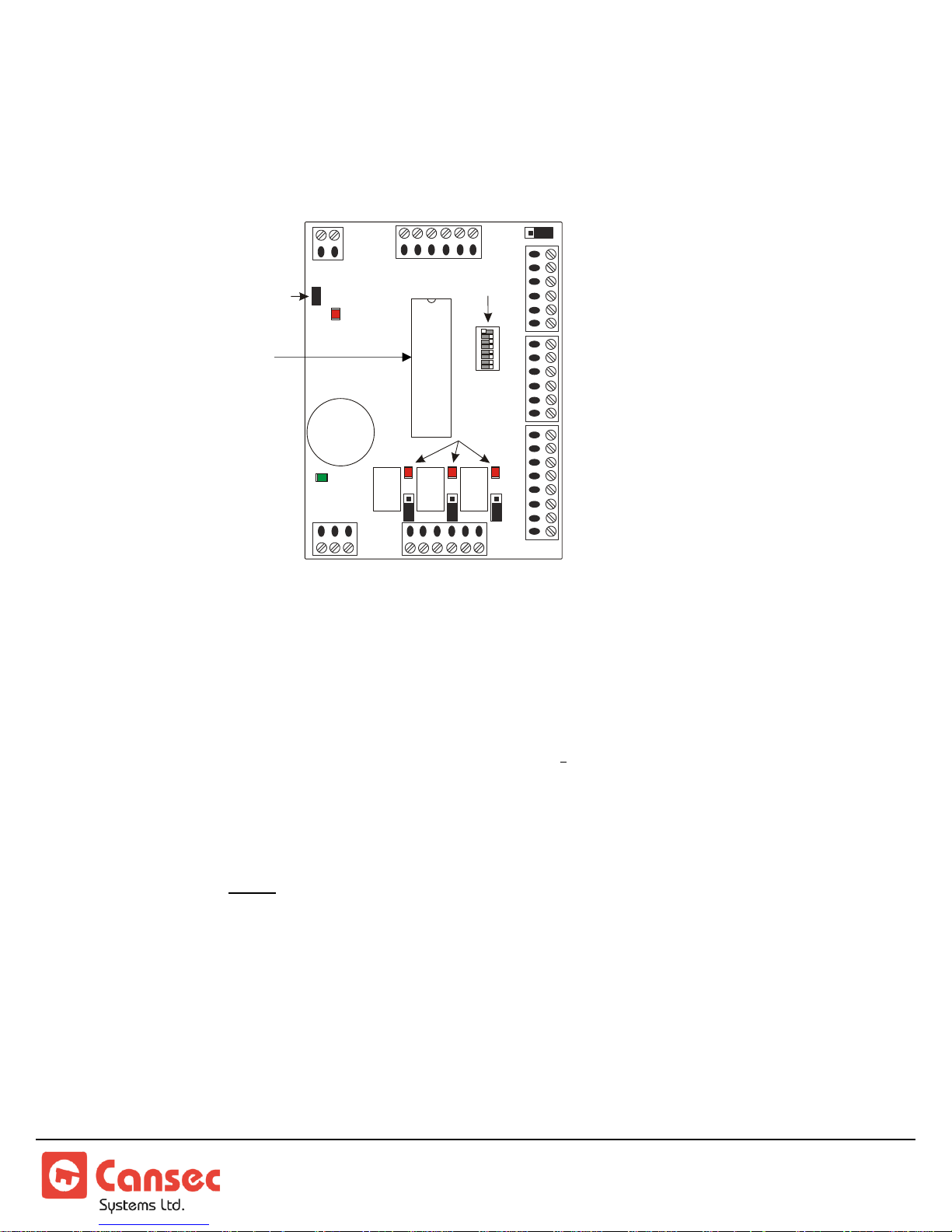
SmartLock Controller Layout
1 2 3 4 5 6 7 8
ON
WIEGAND
DATA LED
COMMS
LED
OFF
ON
8
1
+5V
+12V
N/O
N/C
N/O N/O
N/C N/C
+12 VDC
INPUT
EXIT READER
(WIEGAND)
ENTRY READER
(WIEGAND)
ENTRY READER
or
PROGRAMMING MODULE
(iBUTTON)
DOOR CONTACT
EXIT BUTTON
DOOR OPERATOR
(INPUTS)
LOCK CONTROL
DOOR OPERATOR
FORCED/HELD OPEN
(OUTPUTS)
RS-485
COMMUNICATIONS
RELAY LEDS
ADDRESS
SWITCH
READER VOLTAGE
SELECTOR
DEFAULT
(DO NOT CHANGE)
LOCK
FORCED
/ DHO
DOOR
OPER.
FIRMWARE CHIP
Important Notes:
1. Each controller must have a unique address.
Refer to the Controller Address Table.
2. Exit reader must be Wiegand only. Native iButton
for exit.
3. Before connecting readers with power ON, make sure Reader Voltage
Selection Jumper is set to proper voltage for reader, otherwise the reader
may be damaged.
4. Do NOT connect power to any inputs on the controller.
5. The Door Contact Input should be bypassed, if not used, by using a
jumper wire across the input or setting the switch to ignore the input. Refer
to the Door Contact Bypass Switch Setting.
6. This controller utilizes “self-resetting” fuses. There are no field-serviceable
parts.
®
reader not supported
SmartLock® Controller Page 8 of 26
Installation Manual Nov 2018 • Rev. 3.2
Page 9

LED INDICATORS
1. Relay LEDs turn RED when the corresponding relay is ON or
ACTIVATED.
2. The Wiegand data LED is normally ON and briefly flickers when valid
Wiegand data is received from the reader. If Wiegand data is not valid
or not supported, this LED will stay OFF until the next valid card is
read.
3. The communication LED will flicker GREEN while communicating
with SmartLock software.
MOUNTING
Up to two SmartLock controllers can be mounted in the SmartLock
enclosure along with a Cansec 12 VDC power supply and a backup battery.
SmartLock® Controller Page 9 of 26
Installation Manual Nov 2018 • Rev. 3.2
Page 10
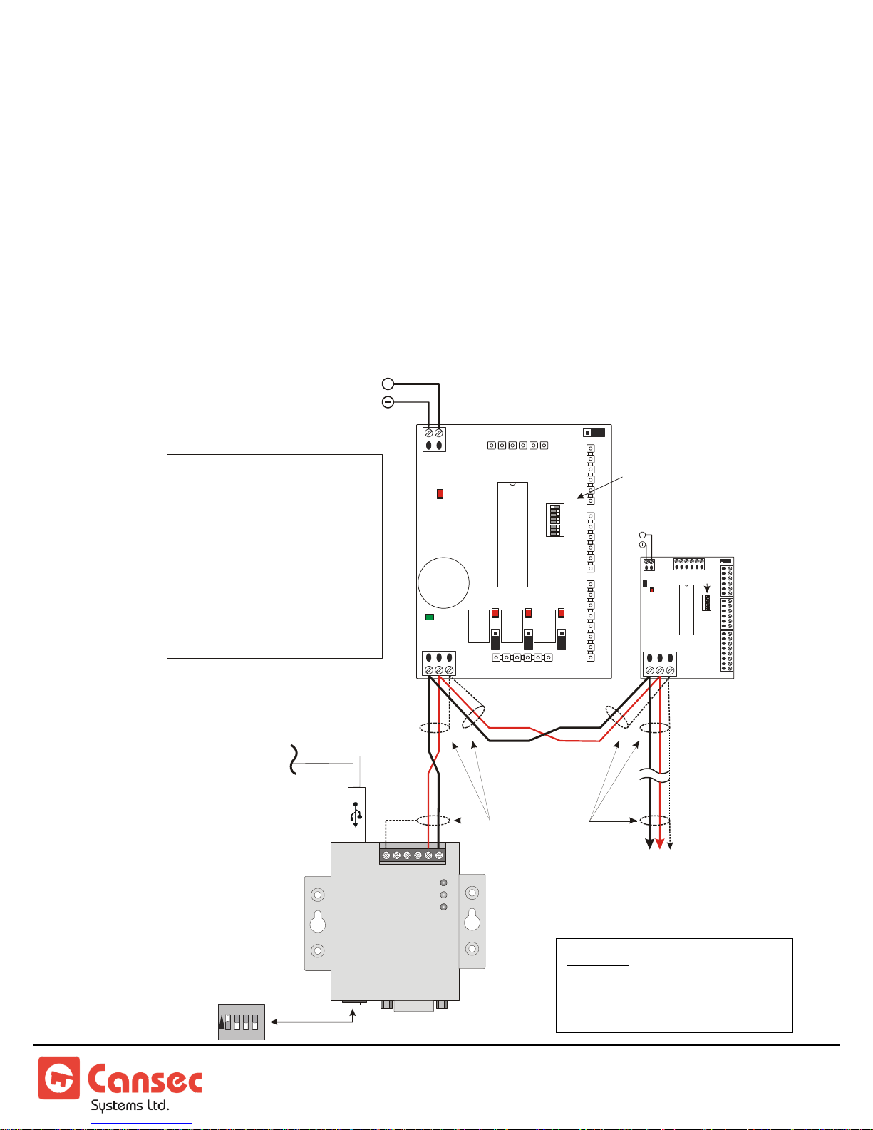
RS-485 Communications Wiring
NOTE: The EIA RS-485
standard does not permit
T-Tap or Star connections.
1 2 3 4 5 6 7 8
ON
COMMS
LED
SMARTLOCK
CONTROLLER
#1
6 5 4 3 2 1
Serial
SW
USB
PWR
RxD
TxD
1 2 3 4
ON
RS-485
DIPSWITCH
SETTINGS
TO USB PORT
(CABLE SUPPLIED)
SHIELD
B A GND
GND
+12 VDC
SMARTLOCK
CONTROLLER
#2
ON
8
1
+5V
+12V
N/O
N/C
OFF
N/C N/C
N/O N/O
- Each Smartlock controller must
have a unique address
- For communication wiring, use 22
AWG, twisted pair, stranded,
shielded cable, 2000 ft ( ) MAX
total length.
609 m
- Use the CLAUSB factory default
jumper settings for communications
with Smartlock controllers.
open the CLAUSB and change the
jumper settings.
DO NOT
NOTES:
CLAUSB
ADDRESS “1” SHOWN
(Dipswitch 1 is OFF)
ON
OFF
ON
8 1
+5V
+12V
ADDRESS
SWITCH
B A GND
B A GND
TO OTHER
SMARTLOCK
CONTROLLERS
- 30 CONTROLLERS MAXIMUM
- 609 m (2000 ft.) MAXIMUM LENGTH
SHIELD
GND
+12 VDC
Up to 30 SmartLock access control panels may be connected on an RS-485
bus.
NOTE:
For legacy CLA50 and CLAUSB2 communications device wiring please see
Appendix section.
CLAUSB COMMUNICATIONS DEVICE
SmartLock® Controller Page 10 of 26
Installation Manual Nov 2018 • Rev. 3.2
Page 11
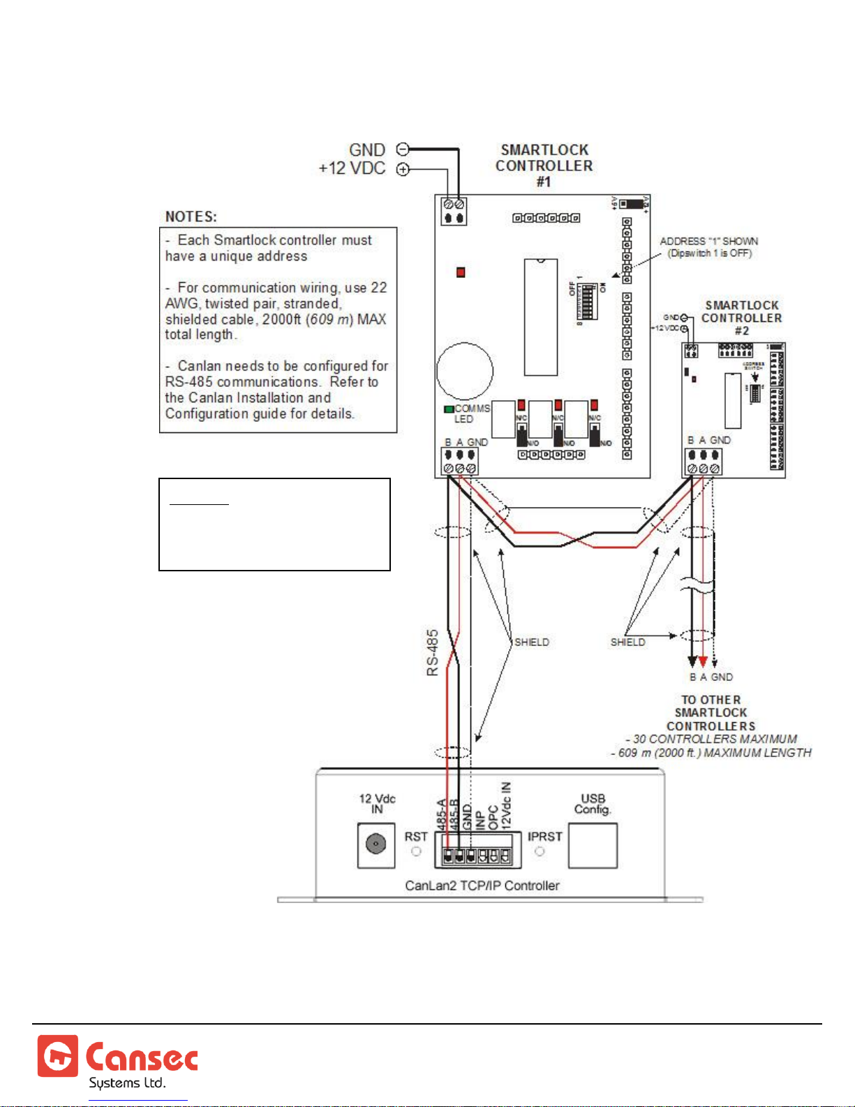
CANLAN NETWORK COMMUNICATIONS DEVICE
NOTE: The EIA RS-485
standard does not permit
T-Tap or Star connections.
SmartLock® Controller Page 11 of 26
Installation Manual Nov 2018 • Rev. 3.2
Page 12
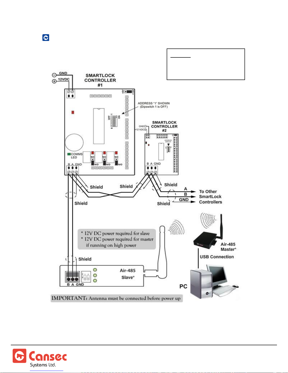
AIR-485 COMMUNICATIONS DEVICE
NOTE: The EIA RS-485
standard does not permit
T-Tap or Star connections.
SmartLock® Controller Page 12 of 26
Installation Manual Nov 2018 • Rev. 3.2
Page 13
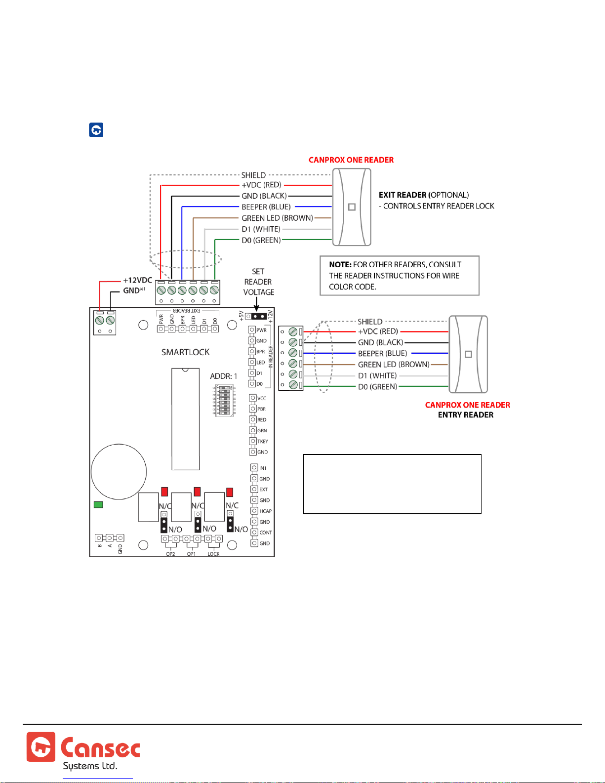
Reader Wiring
CABLE: 22 AWG, 6 CONDUCTORS,
NON-TWISTED PAIR, OVERALL
SHIELDED, MAX. DISTANCE IS
500ft (152 m)
WIEGAND READER
IMPORTANT: Before applying power to the controller, verify that the
reader voltage jumper is set correctly for the reader being connected.
Connecting a 5 V reader to a 12 V power supply will damage the reader.
NOTE: The SmartLock® controller supports Cansec’s 37-bit format as well as
standard 26-bit format.
SmartLock® Controller Page 13 of 26
Installation Manual Nov 2018 • Rev. 3.2
Page 14
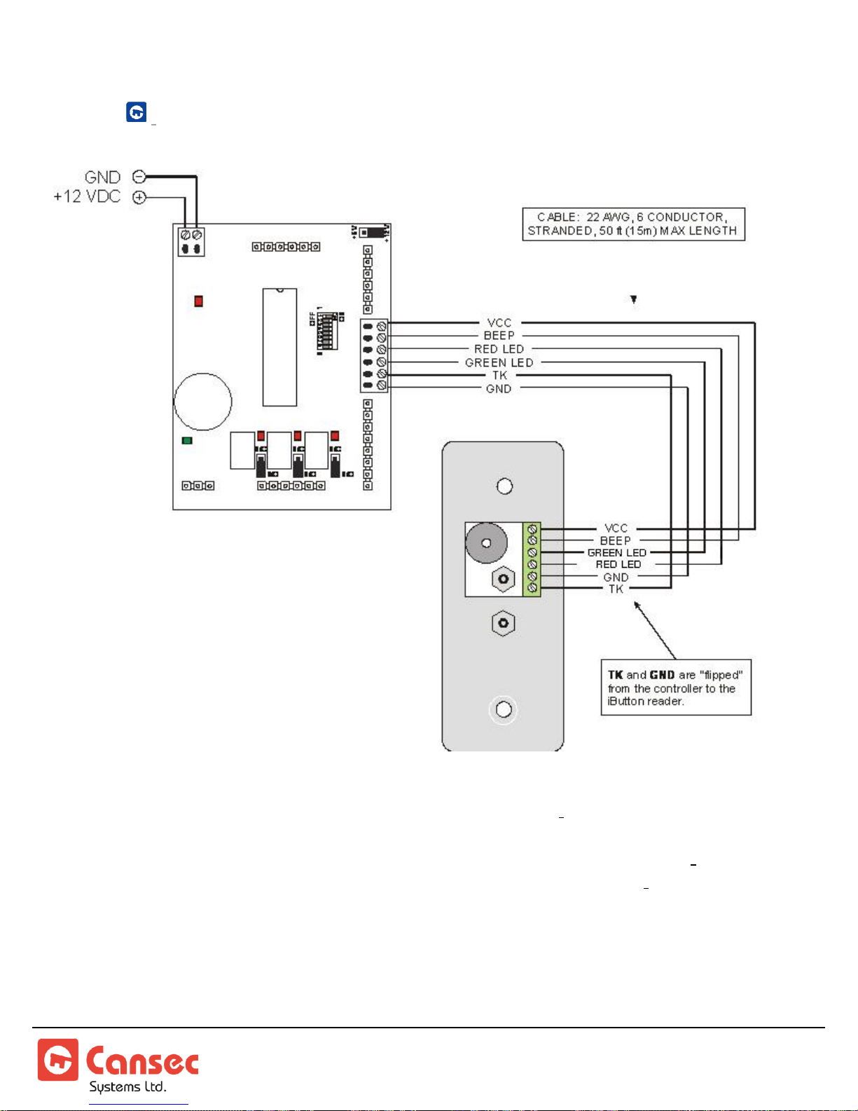
iBUTTON
®
READER
NOTE: Exit reader not supported with SmartLock iButton readers.
NOTE: If using the SmartLock Connect Programming Module with iButton
readers, connect the programming module in parallel with the iButton
reader.
SmartLock® Controller Page 14 of 26
Installation Manual Nov 2018 • Rev. 3.2
Page 15
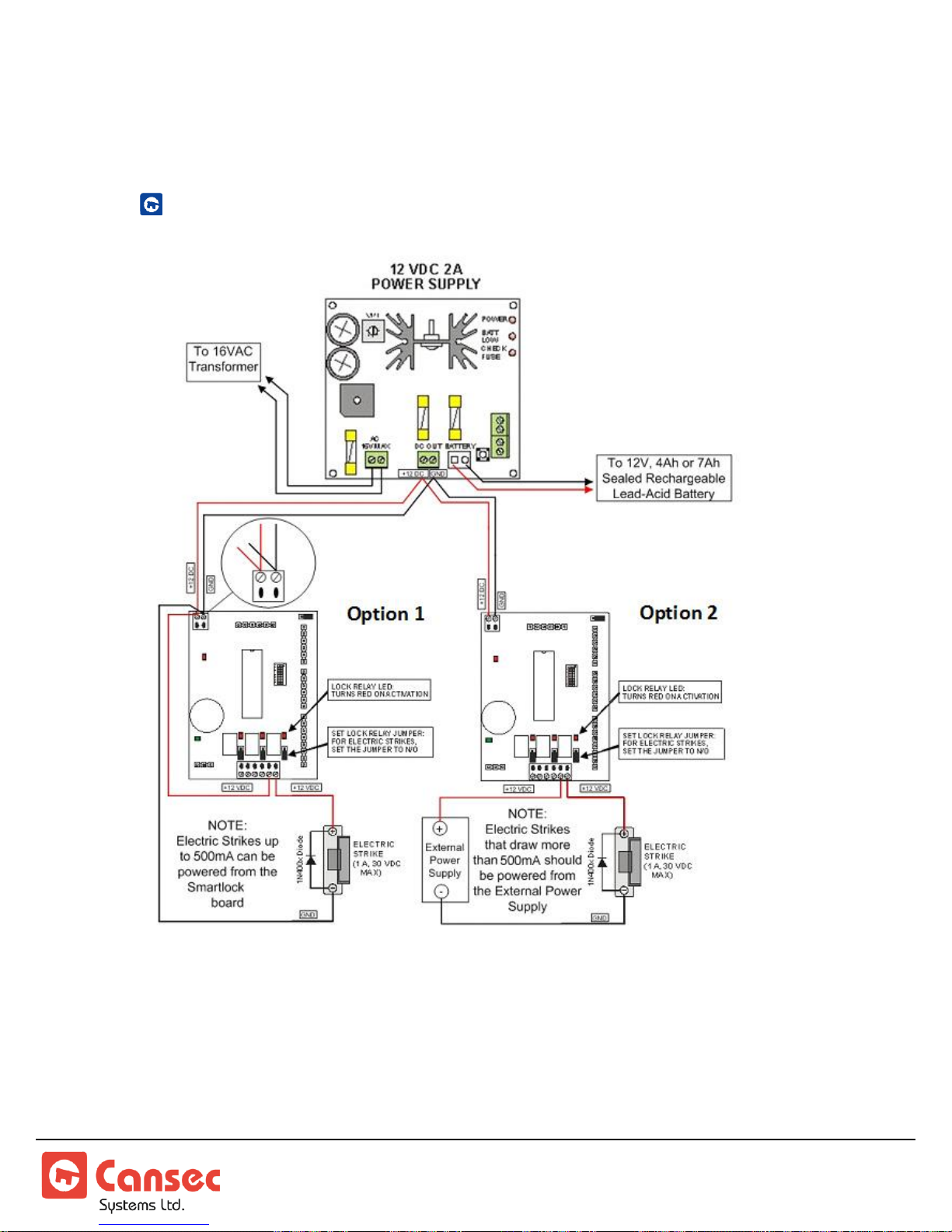
Lock Output Relay Wiring
≤ 500 mA
> 500 mA
DC ELECTRIC STRIKES
NOTE: Use 1N400x series diode as shown, to prevent “back EMF” from
damaging the controller.
SmartLock® Controller Page 15 of 26
Installation Manual Nov 2018 • Rev. 3.2
Page 16
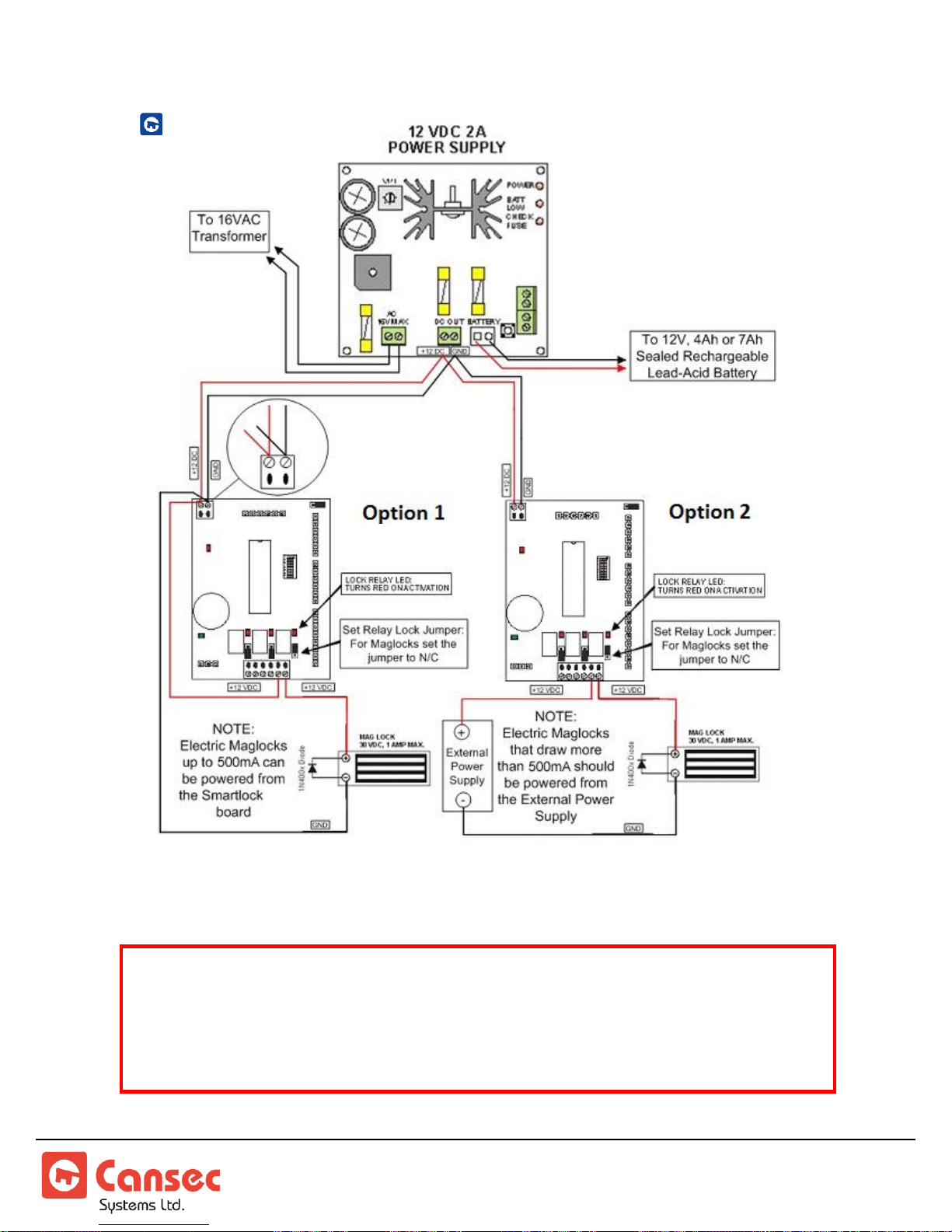
DC MAGLOCKS
> 500 mA
≤ 500 mA
IMPORTANT: In some jurisdictions, the use of a UL approved power
supply and connection to the fire alarm system for emergency release
may be required. Installers should contact the local authority having
jurisdiction to verify the specific requirements. Also, a building permit
may be required in some jurisdictions for the installation of maglocks.
NOTE: Use 1N400x series diode as shown to prevent “back EMF” from damaging
the controller if the maglock is not equipped with sufficient spike and surge
protection. Check the maglock specifications for details.
SmartLock® Controller Page 16 of 26
Installation Manual Nov 2018 • Rev. 3.2
Page 17
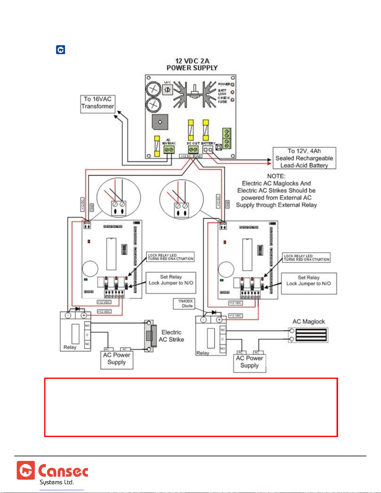
AC MAGLOCKS AND AC ELECTRIC STRIKES
IMPORTANT: In some jurisdictions, the use of a UL approved power
supply and connection to the fire alarm system for emergency release may
be required. Installers should contact the local authority having
jurisdiction to verify the specific requirements. Also, a building permit
may be required in some jurisdictions for the installation of maglocks.
SmartLock® Controller Page 17 of 26
Installation Manual Nov 2018 • Rev. 3.2
Page 18
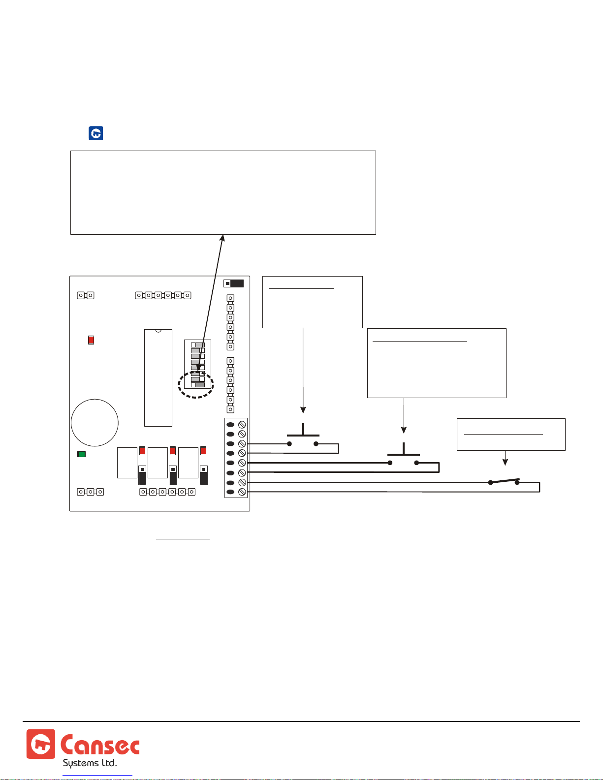
Input Wiring
1 2 3 4 5 6 7 8
ON
EXIT BUTTON
- NORMALLY OPEN
- MOMENTARY TO
ACTIVATE
HANDICAP BUTTON
- NORMALLY OPEN
- MOMENTARY TO ACTIVATE
- ENABLED ONLY AFTER
VALID CARD OR
EXIT BUTTON
DOOR CONTACT
- NORMALLY CLOSE
EXIT
HC
DC
IF YOU ARE CONNECTING A DOOR CONTACT
SET DIP SWITCH 8 TO OFF (LEFT)
IF YOU ARE CONNECTING A DOOR CONTACT
SET DIP SWITCH 8 ON (RIGHT)
NOT
OFF
EXIT BUTTON, HANDICAP BUTTON, DOOR CONTACT
NOTE: DO NOT apply power or attempt to switch any current through
these inputs as this will result in damage to the controller.
NOTE: If not connecting a door contact, make sure you set switch position 8
to ON (right in orientation shown) to bypass/disable the door contact input.
Otherwise, the door will be in alarm condition.
NOTE: Exit Button requires momentary closure to activate relay. Door
Contact is used for forced-entry and door-held-open annunciation, and also
deactivates the lock relay when the door closes.
SmartLock® Controller Page 18 of 26
Installation Manual Nov 2018 • Rev. 3.2
Page 19
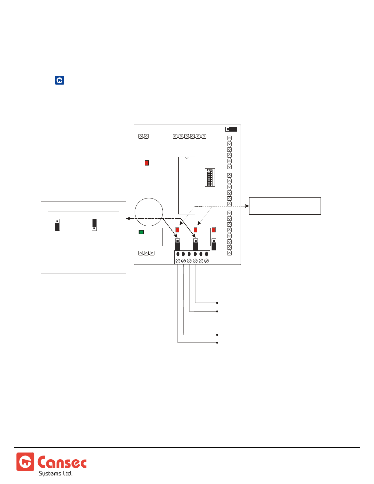
Output Wiring
1 2 3 4 5 6 7 8
ON
OFF
ON
8
1
+5V
+12V
N/O
N/C
N/O N/O
N/C N/C
SET RELAY CONTACTS
= N/O = N/C
LOCK
DOOR
OPER.
FORCED
/ DHO
RELAY LEDS TURN
ON ACTIVATION
RED
DOOR OPERATOR OUTPUT
ACTIVATED MOMENTARILY WHEN
HANDICAP BUTTON IS DEPRESSED
AFTER LOCK RELAY IS ACTIVATED.
FORCED ENTRY/DHO OUTPUT
ACTIVATED ON FORCED ENTRY AND/OR
DHO ALARM AS CONFIGURED IN SOFTWARE
N/O: RELAY CLOSES ON
ACTIVATION
N/C: RELAY OPENS ON
ACTIVATION
DOOR OPERATOR, FORCED ENTRY, DOOR-HELD-OPEN
Use dry contact relays.
NOTE: Maximum power through any of these relays is 30 VDC at 1 A.
NOTE: Door Operator requires momentary closure to activate relay.
SmartLock® Controller Page 19 of 26
Installation Manual Nov 2018 • Rev. 3.2
Page 20
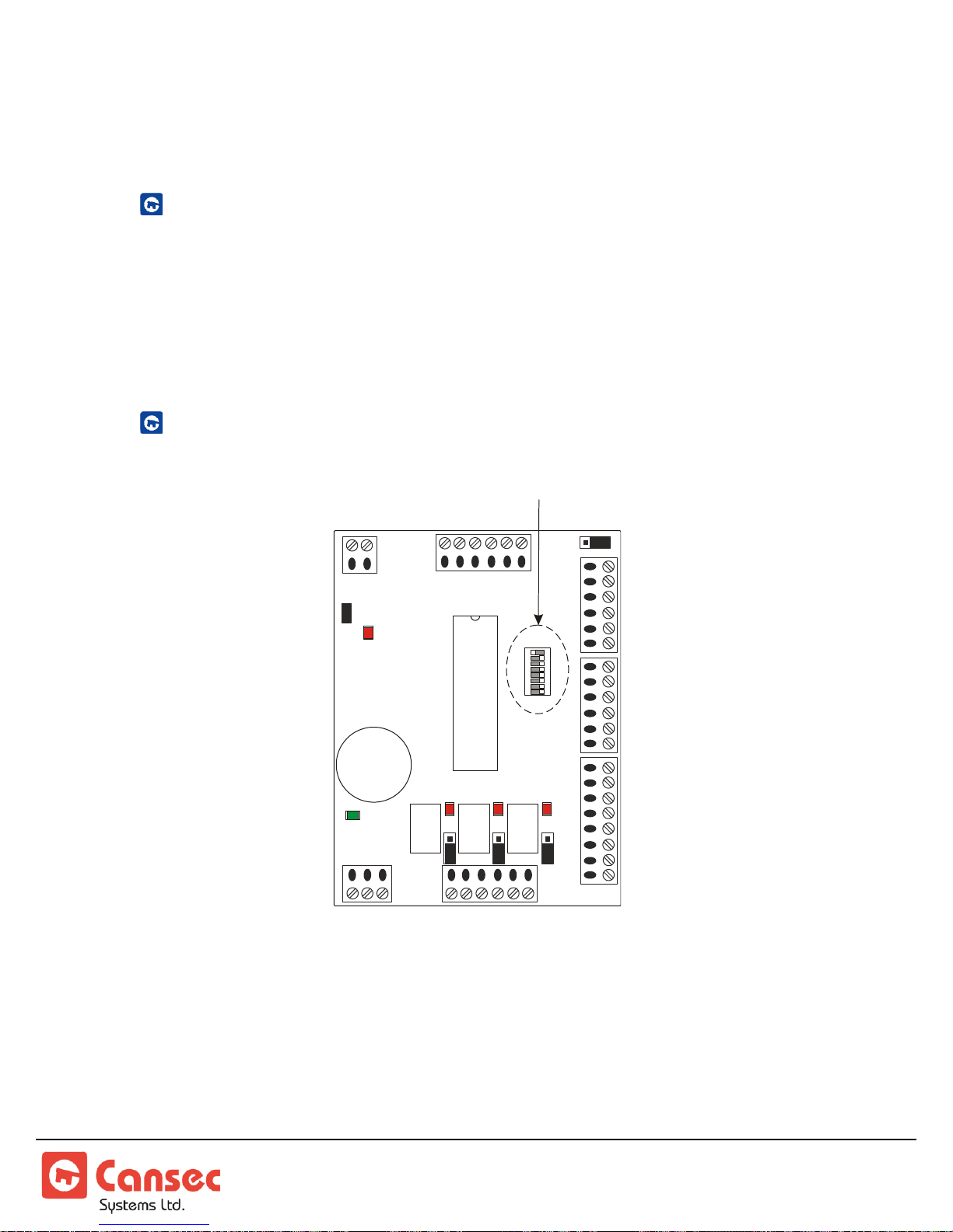
DIP Switch
1 2 3 4 5 6 7 8
ON
WIEGAND
DATA LED
COMMS
LED
OFF
ON
8
1
+5V
+12V
N/O
N/C
N/O N/O
N/C N/C
DIP
SWITCH
LOCK
FORCED
/ DHO
DOOR
OPER.
FUNCTION
The DIP switch is used:
to erase the controller’s memory and run diagnostics
to set the baud rate
to enable or bypass the door contact input
to set the controller address from 1 to 30.
LOCATION
SmartLock® Controller Page 20 of 26
Installation Manual Nov 2018 • Rev. 3.2
Page 21

ERASE CONTROLLER MEMORY, DIAGNOSTICS
1. Disconnect communication and device wiring.
2. To erase controller memory (factory default), set all switches to the
OFF position (left on diagram above).
3. Disconnect power from the board momentarily then re-connect power.
4. The controller’s memory will be erased. All three relays will cycle
ON/OFF once the memory has been cleared. Relay outputs can be
verified during this stage.
NOTE: If the relays do not cycle ON/OFF, there may be a problem
with the unit.
5. Continue to set controller address and door contact bypass switch
settings.
SET CONTROLLER BAUD RATE
The default baud rate is 9600 bps with dip switch #7 set to on position.
SmartLock Pro, with firmware version 1.56 and up, also supports 38,400
bps. Follow the steps below to adjust the baud rate.
1. Set dip switch #7 to off position to enable 38,400 bps.
2. Ensure that the setting in the software is set to 38,400.
NOTE: Switch setting changes do not take effect until the power is
disconnected, then reconnected.
SmartLock® Controller Page 21 of 26
Installation Manual Nov 2018 • Rev. 3.2
Page 22
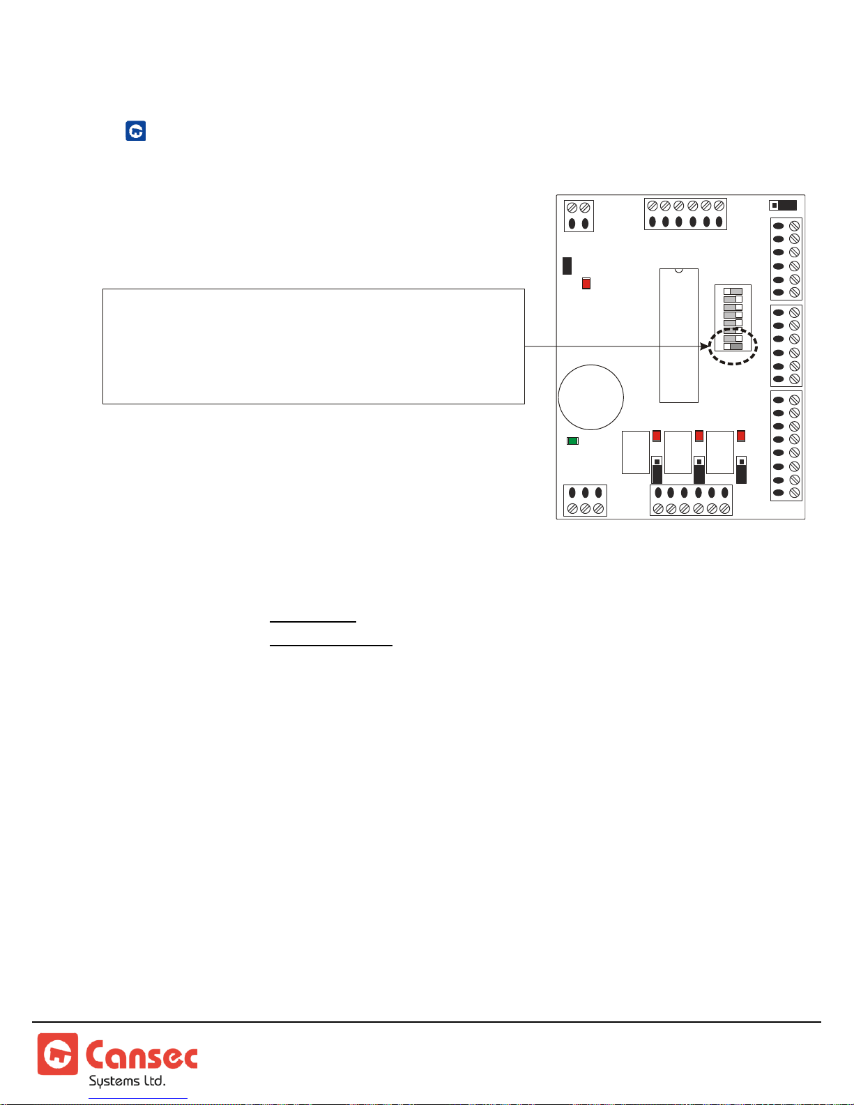
DOOR CONTACT BYPASS SWITCH SETTING
WIEGAND
DATA LED
COMMS
LED
+5V
+12V
N/O
N/C
N/O N/O
N/C N/C
LOCK
FORCED
/ DHO
DOOR
OPER.
1 2 3 4 5 6 7 8
ONOFF
IF YOU ARE CONNECTING A DOOR CONTACT
SET DIP SWITCH 8 TO OFF (LEFT)
IF YOU ARE CONNECTING A DOOR CONTACT
SET DIP SWITCH 8 ON (RIGHT)
NOT
Door Contact Connected: Set switch 8 OFF (LEFT on diagram)
Door Contact Not Connected: Set switch 8 ON (RIGHT on diagram)
NOTE: If door contacts are not installed, but door contacts are enabled on
the control panel via switch 8, unlock schedules will fail to take effect.
SmartLock® Controller Page 22 of 26
Installation Manual Nov 2018 • Rev. 3.2
Page 23
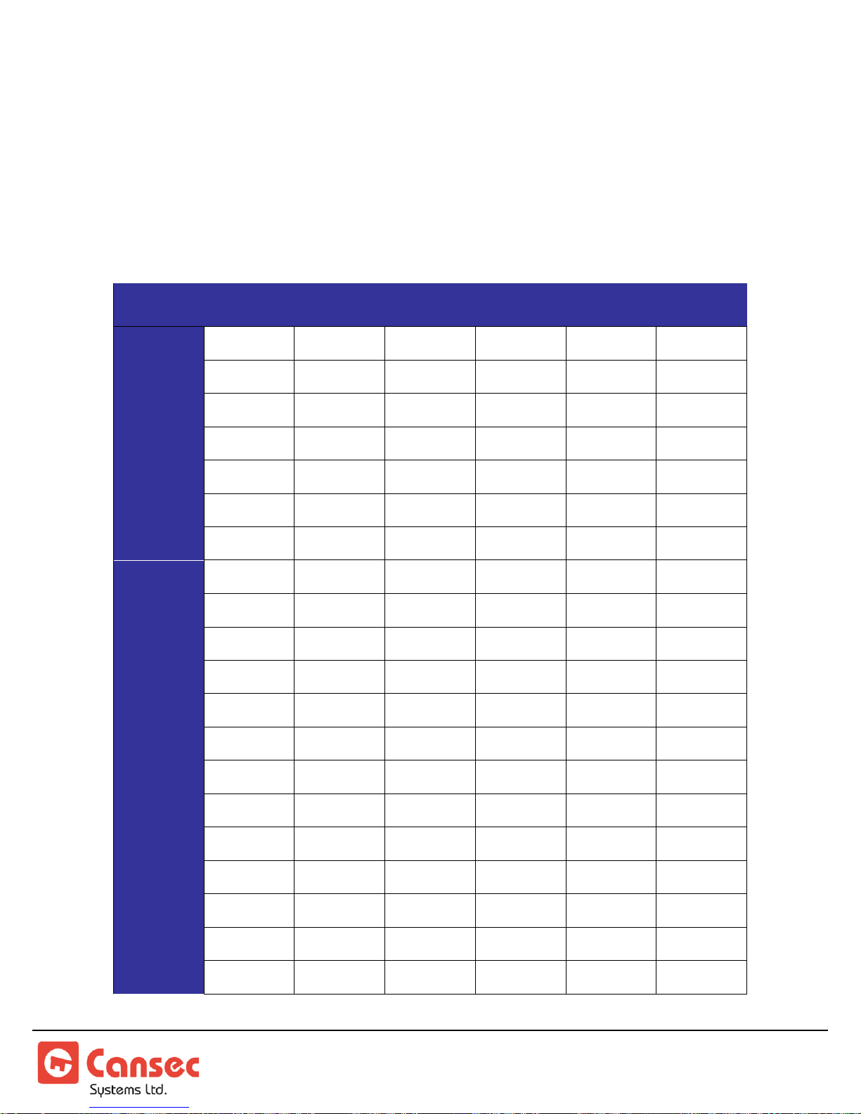
Controller Address Table
ADDRESS
SW-1
SW-2
SW-3
SW-4
SW-5
SW-6
1
OFF
ON
ON
ON
ON
ON
2
ON
OFF
ON
ON
ON
ON
3
OFF
OFF
ON
ON
ON
ON
4
ON
ON
OFF
ON
ON
ON
5
OFF
ON
OFF
ON
ON
ON
6
ON
OFF
OFF
ON
ON
ON
7
OFF
OFF
OFF
ON
ON
ON 8 ON
ON
ON
OFF
ON
ON
9
OFF
ON
ON
OFF
ON
ON
10
ON
OFF
ON
OFF
ON
ON
11
OFF
OFF
ON
OFF
ON
ON
12
ON
ON
OFF
OFF
ON
ON
13
OFF
ON
OFF
OFF
ON
ON
14
ON
OFF
OFF
OFF
ON
ON
15
OFF
OFF
OFF
OFF
ON
ON
16
ON
ON
ON
ON
OFF
ON
17
OFF
ON
ON
ON
OFF
ON
18
ON
OFF
ON
ON
OFF
ON
19
OFF
OFF
ON
ON
OFF
ON
20
ON
ON
OFF
ON
OFF
ON
Set the unique address of each controller from 0 to 30 as per the table below.
The same address used must be programmed in the software in order to
establish communications. Switch setting changes do not take effect until the
power is disconnected, then reconnected.
SmartLock® Controller Page 23 of 26
Installation Manual Nov 2018 • Rev. 3.2
Page 24
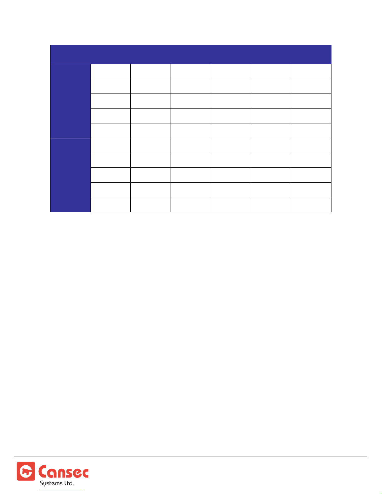
ADDRESS
SW-1
SW-2
SW-3
SW-4
SW-5
SW-6
21
OFF
ON
OFF
ON
OFF
ON
22
ON
OFF
OFF
ON
OFF
ON
23
OFF
OFF
OFF
ON
OFF
ON
24
ON
ON
ON
OFF
OFF
ON
25
OFF
ON
ON
OFF
OFF
ON
26
ON
OFF
ON
OFF
OFF
ON
27
OFF
OFF
ON
OFF
OFF
ON
28
ON
ON
OFF
OFF
OFF
ON
29
OFF
ON
OFF
OFF
OFF
ON
30
ON
OFF
OFF
OFF
OFF
ON
NOTES:
1. Switch setting changes do not take effect until the power is
disconnected, then reconnected.
SmartLock® Controller Page 24 of 26
Installation Manual Nov 2018 • Rev. 3.2
Page 25
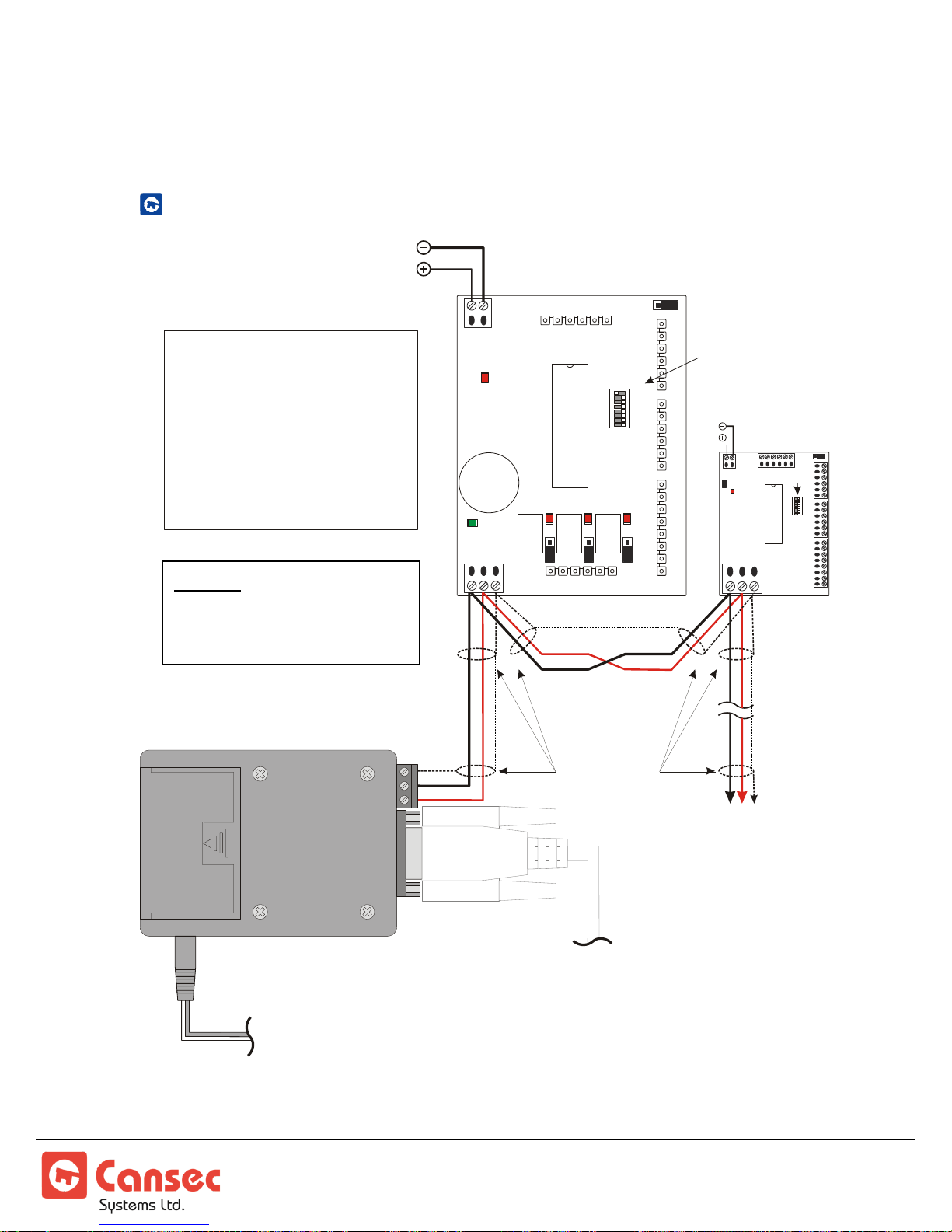
Appendix
1 2 3 4 5 6 7 8
ON
COMMS
LED
SMARTLOCK
CONTROLLER
RS-485
B A GND
GND
+12 VDC
ON
8
1
+5V
+12V
N/O
N/C
OFF
N/C N/C
N/O N/O
- Each Smartlock controller must
have a unique address
- For communication wiring, use 22
AWG, twisted pair, stranded,
shielded cable, 2000 ft ( ) MAX
total length.
609 m
- open the CLA50 and
change the jumper settings or DIP
switch settings.
DO NOT
NOTES:
ADDRESS “1” SHOWN
(Dipswitch 1 is OFF)
GND
B
A
12 VDC PLUG IN TRANSFORMER
2.1 mm PLUG, CENTRE POSITIVE
(SUPPLIED)
TO COMPUTER
DB9 SERIAL PORT
(CABLE SUPPLIED)
ON
OFF
ON
8
1
+5V
+12V
ADDRESS
SWITCH
B A GND
B A GND
TO OTHER
SMARTLOCK
CONTROLLERS
- 30 CONTROLLERS MAXIMUM
- 609 m (2000 ft.) MAXIMUM LENGTH
SHIELDSHIELD
GND
+12 VDC
SMARTLOCK
CONTROLLER
#2
NOTE: The EIA RS-485
standard does not permit
T-Tap or Star connections.
CLA50 COMMUNICATIONS WIRING
SmartLock® Controller Page 25 of 26
Installation Manual Nov 2018 • Rev. 3.2
Page 26
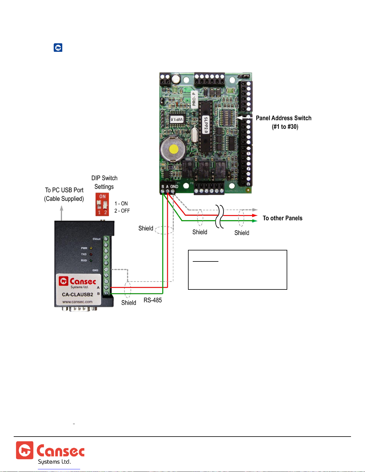
CLAUSB2 COMMUNICATIONS WIRING
NOTE: The EIA RS-485
standard does not permit
T-Tap or Star connections.
SmartLock Controller
® SmartLock is a registered trademark of Cansec Systems Ltd.
® iButton is a registered trademark of Maxim Integrated Products, Inc.
SmartLock® Controller Page 26 of 26
Installation Manual Nov 2018 • Rev. 3.2
 Loading...