

Page 1
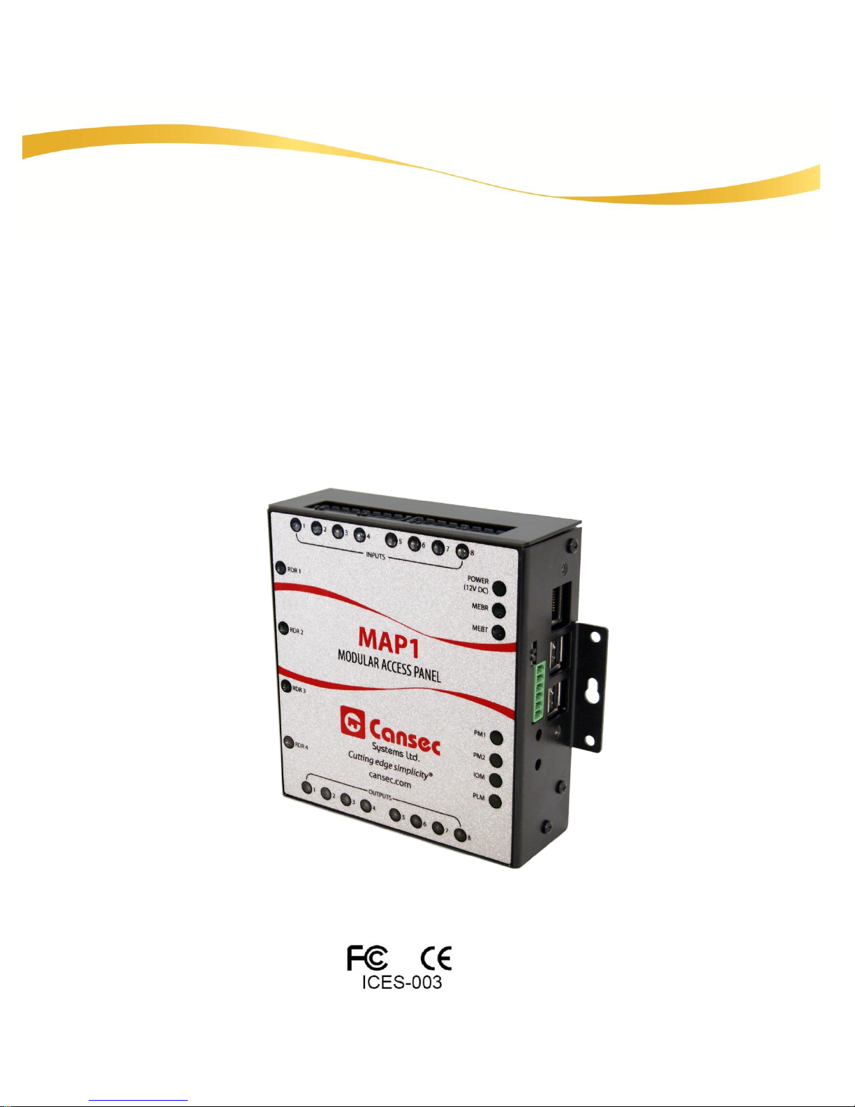
MAP1 Controller
INSTALLATION MANUAL
June 2018
Page 2

Table of Contents
Introduction .................................................................................................................................................................. 3
Specifications .............................................................................................................................................................. 4
MAP1 Controller Layout .......................................................................................................................................... 7
Panel Installation ...................................................................................................................................................... 10
Controller Power Connection ......................................................................................... 10
Entry Reader Wiring ........................................................................................................ 11
Entry and Exit Reader Wiring ......................................................................................... 12
Exit Button and Door Contact Wiring ............................................................................ 12
Lock Output and Multi-Function Relay Wiring ............................................................. 15
Input and Output Point Wiring ....................................................................................... 17
Appendix ...................................................................................................................................................................... 20
MAP1 System Indicators ................................................................................................. 21
Power Connector ............................................................................................................. 22
PB1 – Shutdown Button .................................................................................................. 23
PB2 – IP Reset Button and Static IP Address Configuration ..................................... 23
USB IP Configuration Tool.............................................................................................. 26
Forced Entry Output ........................................................................................................ 30
Door Held Open Output ................................................................................................... 30
Alarm Shunt Output ......................................................................................................... 30
Door Operator Output – All Cards ................................................................................. 31
Door Operator Output – Handicap Cards only ............................................................. 31
Copyright 2018 Cansec Systems Ltd.
All rights reserved.
MAP1 Page 2 of 31
Installation Manual June 2018 • Rev. 1.6
Page 3

Introduction
Note: Must have latest approved PLM and IOM firmware version for compatibility to this document.
255 Access Schedules
On board Triggers independent of host connection
Supports 100,000 individual user card IDs
Supports any Wiegand card (64 bit max.)
Supports up to 4 readers/door combinations
Supports Door Contact and RTE connection per reader/door
Supports Input points (with or without supervision) and Output points
Ease of future software/firmware upgrades
First Access mode or Webster mode or Cloud Lock mode
Key Features
Cansec Systems’ MAP1 (Modular Access Panel) incorporates a mini-computer
called the Panel Logic Module (PLM) utilizing Ethernet connectivity and an Input
Output Module (IOM) which incorporates a 32-bit processor in this new
architecture. This allows for a fast, high capacity access control system with a lower
cost per reader/door system implementation. The MAP1 architecture has the ability
to flash applications and firmware updates into the control panel using the
Ethernet connection.
The standard MAP1 is factory provisioned for two doors in First Access mode.
Door provisioning and mode (First Access – application based or Webster – web
based or Cloud Lock – cloud based) can be changed with a provisioning file provided
by Cansec upon purchase. Only one mode can be run at a time and data cannot be
shared between modes. Input and Output points are available when not used on a
provisioned door.
Cloud Lock.
The MAP1 allows for 100,000 individual cardholders, using raw Wiegand data up
to 64 bits per card ID. This allows the use of many proprietary Wiegand cards
without the need for data conversion. The readers can be Cansec’s CanProx One
Proximity Readers (AWID or HID card technology) or one of many other popular
Wiegand readers.
Note
: I/O points may be available in future release of Webster and
MAP1 Page 3 of 31
Installation Manual June 2018 • Rev. 1.6
Page 4

Specifications
See power supply notes in Appendix section for more information.
Controller Power Requirements (No Readers Attached, Ethernet Connected)
Maximum Current (all Relays, LEDs ON)………………………………… 350 mA
Temperature Range
Operating ……………………………………………………………………………….. -20˚C to 60˚C
Relative Humidity
Operating ………………………………………………………..……………………… 20% to 80%
Auto Resettable Fuses
MAP1 Main 12V DC……………………………………………………………………………1 A
Each Reader Pair ……………………………………………………………………………………1 A
Output Relays
All Relays (8 per panel) Form ‘C’ …………………………………SPDT 6 A @ 30 VDC
Inputs per Provisioned Doors (Supervised or Non-Supervised)
Door Contact (2 per MAP1) …………………………Requires normally closed contact
(On/Off door switch)
Exit Button (2 per MAP1) ………………..………………Requires normally open contact
(Momentary push button switch)
Reader Cable
Wiegand Readers ........................................ 6 conductor (twisted pair not required)
.............................................................................. 22 AWG, overall shield
........................................................................ 152 m [500 ft] max. Length
NOTE: Consult reader specifications as 18-gauge wire may be required for power
Dimensions & Weight
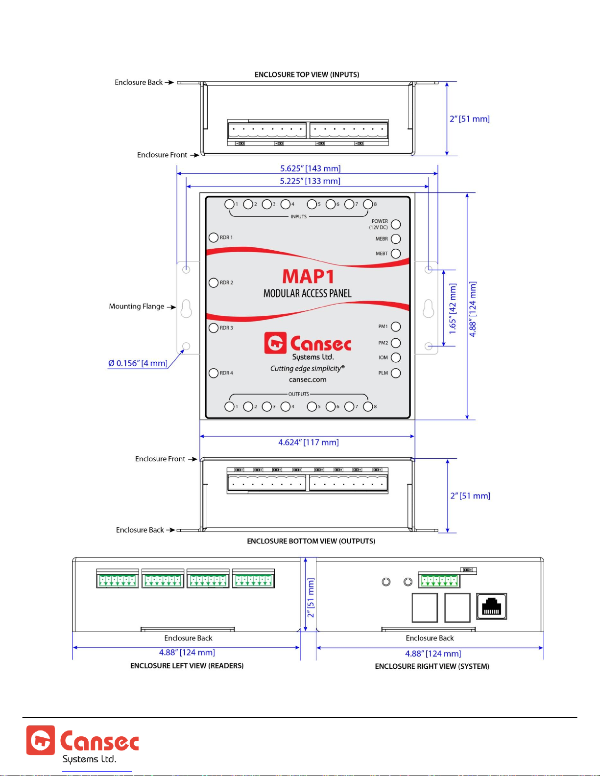
MAP1 Enclosure ……………………………………………..4.6” (W) x 4.9” (H) x 2.0” (D)
[11.7 cm (W) x 12.4 cm (H) x 5.1 cm D)]
Enclosure plus Controller Weight ..................................................... 500 g [17.6 oz]
MAP1 Page 4 of 31
Installation Manual June 2018 • Rev. 1.6
Page 5
Note: Specifications subject to change without notice.
MAP1 Page 5 of 31
Installation Manual June 2018 • Rev. 1.6
Page 6

NOTE: Tech Support will only be provided where product installation guidelines
have been followed.
Specification Notes
CAUTION: EMERGENCY LOCKDOWN
Emergency lockdown functions must operate totally independent of the access
control system and must not rely on operation of card readers, access control
panels, communications networks, communications devices or host software.
Cansec accepts no responsibility for direct or consequential damages resulting from
the failure of emergency lockdown functions which are dependant in any way on
the operation of card readers, access control panels, communications networks,
communications devices or host software.
Wiring Note:
Improper Wiegand cable (new or originally installed cable or missing required
shield connections) may result in high frequency noise on the data lines creating
misreads. This Wiegand misread issue is more evident on longer Wiegand reader
cables. The reader cable may have to be replaced with the correct type of Wiegand
reader cable to improve system reliability.
MAP1 and H1000 Connector Compatibility:
H1000 connectors can be used on the MAP1 controller. The wiring will have to be
adjusted to accommodate for the reversed connector insertion.
MAP1 Page 6 of 31
Installation Manual June 2018 • Rev. 1.6
Page 7
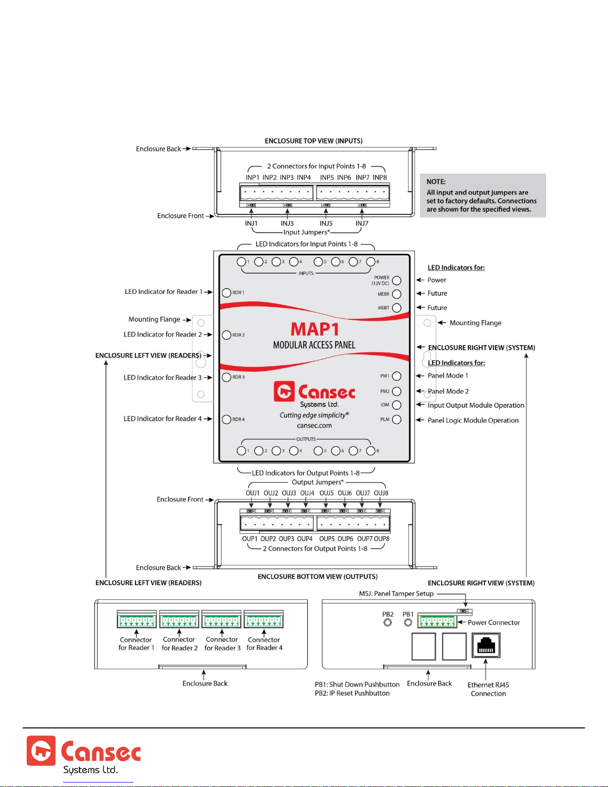
MAP1 Controller Layout
Figure 1
MAP1 Page 7 of 31
Installation Manual June 2018 • Rev. 1.6
Page 8
Important Installation Notes
Figure 2
Controller Provisioning Options:
The MAP1 controller is factory provisioned with default 2-door configuration running
in First Access mode (First Access software is needed – database stored on computer). The
Webster mode (Web based – database stored on panel and no software is needed) and the
Cloud Lock mode (Cloud based – database stored on cloud server) can be enabled with an
authorized provisioning file obtained from Cansec upon purchase. The MAP1 can run
only in one mode at a time and can also be provisioned in one of two options below.
1. Door controller with or without auxiliary input and output points
a. 2–door configuration: 2 lock relays, 2 multi-function relays, 2 REX/RTE, 2
door contacts/DPS, 4 input points and 4 output points.
OR
b. 4–door configuration: 4 lock relays, 4 multi-function relays, 4 REX/RTE, 4
door contacts/DPS, 0 input points and 0 output points.
2. Input and Output controller only. 8 input and 8 output points available. No
door combination i.e. no lock relay and no multi-function relay.
Electrical Information:
1. The MAP1 utilizes a mini-computer and must be operated using a battery
backed up power supply to protect the hardware, system files and data files
from corruption due to power outage. See Note 1 in Appendix section.
2. CAUTION: Do not unplug the MAP1 Power connector if the system is in
operation as data corruption may occur on the MAP1 mini-computer. Please
follow the instructions from the section “PB1 - Shut Down”.
MAP1 Page 8 of 31
Installation Manual June 2018 • Rev. 1.6
Page 9

3. The MAP1 allows for the control of up to 4 door combinations. Ensure that
adequate 12V DC power and current is available, especially when the same
power supply is used for the locks.
4. It is highly recommended to use a separate power supply for locks as they
require a high amount of current for proper operation.
Network Information:
1. The MAP1 Controller is set to acquire an IP address automatically (DHCP).
However, it can be optionally set to a static IP address or reset if necessary. See
Appendix section for more information.
Mechanical Information:
1. The MAP1 has 2 horizontal mounting flanges, which should be used to
attach the product to a stable surface.
2. If required the MAP1 may be mounted inside of a lockable enclosure such as
the CA-SLBOX or CA-H1000ENCL if access is to be limited to the external
connections.
3. If a Lockable external enclosure is used and a Tamper switch is available as in
the CA-SLBOX or CA-H1000ENCL, the MAP1 has a Panel Tamper input
connection available. Connecting the Tamper switch, See figure 14, to this
input will produce an Alarm when opening and closing the enclosure. This
Alarm is sent to the Host computer.
MAP1 Page 9 of 31
Installation Manual June 2018 • Rev. 1.6
Page 10
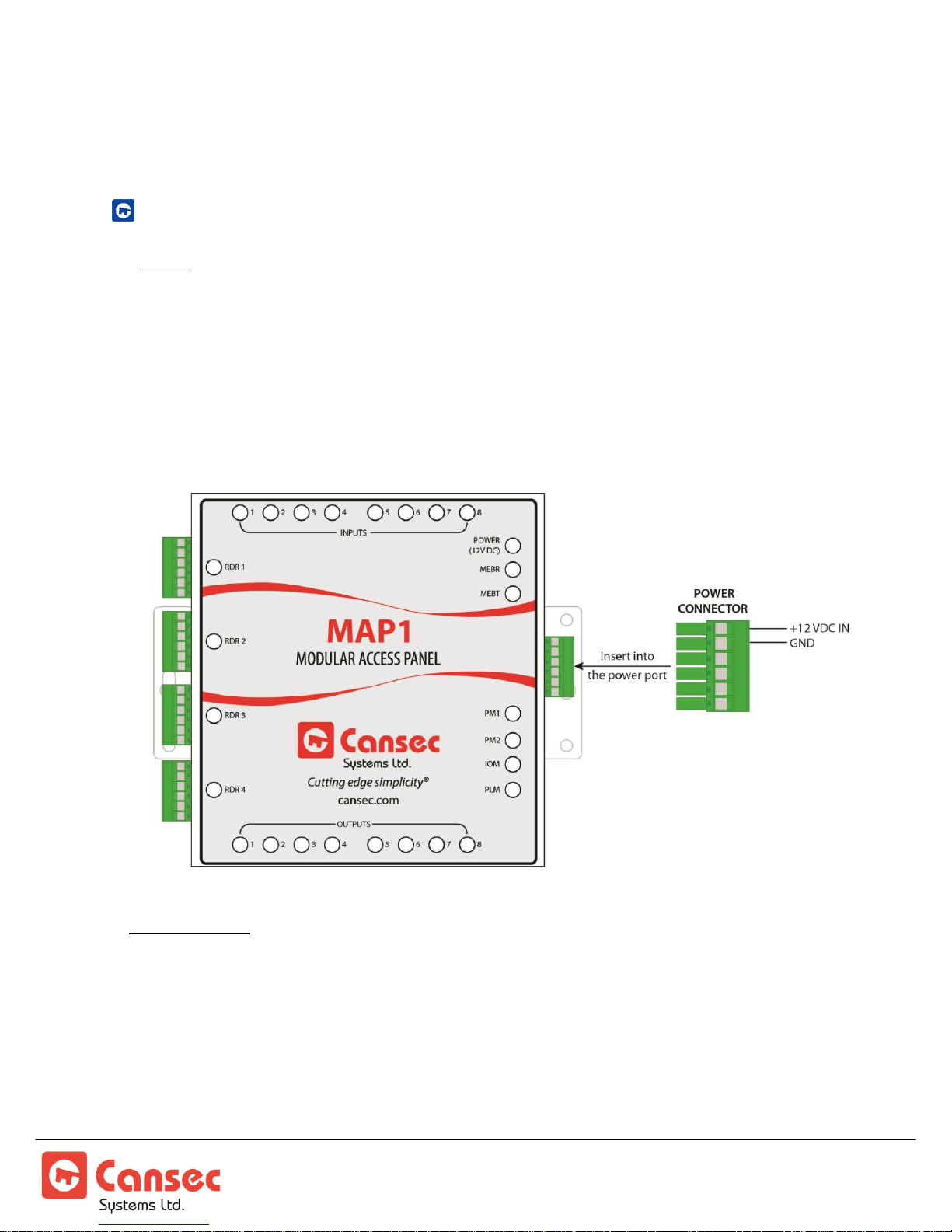
Panel Installation
Figure 3
Mode Indicator: After a complete power up, PM1 LED is on, PM2 LED is off, IOM LED flashes
once every second, PLM LED flashes waiting for a host connection and stays
steady when a connection is established. MAP1 emits beep to indicate
operating mode.
1 Beep – First Access
2 Beeps – Webster
3 Beeps – Cloud Lock
CONTROLLER POWER CONNECTION
Note: See Note 1 in Appendix section for suggested power supplies & backup battery.
The MAP1 requires an external battery backed-up 12 VDC power supply. However,
as many devices can be attached to the MAP1 controller, it may be more cost
effective to use a separate power supply (battery backed-up) just for the MAP1
Controller and a separate power supply which can be sized to supply the amount of
current that the attached high-current devices (locks) will require.
MAP1 Page 10 of 31
Installation Manual June 2018 • Rev. 1.6
Page 11
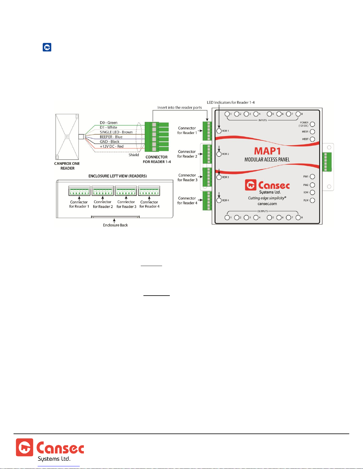
ENTRY READER WIRING
Figure 4
The following diagram shows entry reader wiring only. For entry and optional exit
reader wiring diagram, proceed to the next section.
READER LED ON = Reader Active. Two Inputs and two Outputs are used for
RTE/REX, door contacts well as lock relays and multi-function relays respectively.
READER LED OFF = Reader Inactive. Two Inputs and two Outputs are free to be
used as independent auxilliary Input and Output points.
MAP1 Page 11 of 31
Installation Manual June 2018 • Rev. 1.6
Page 12
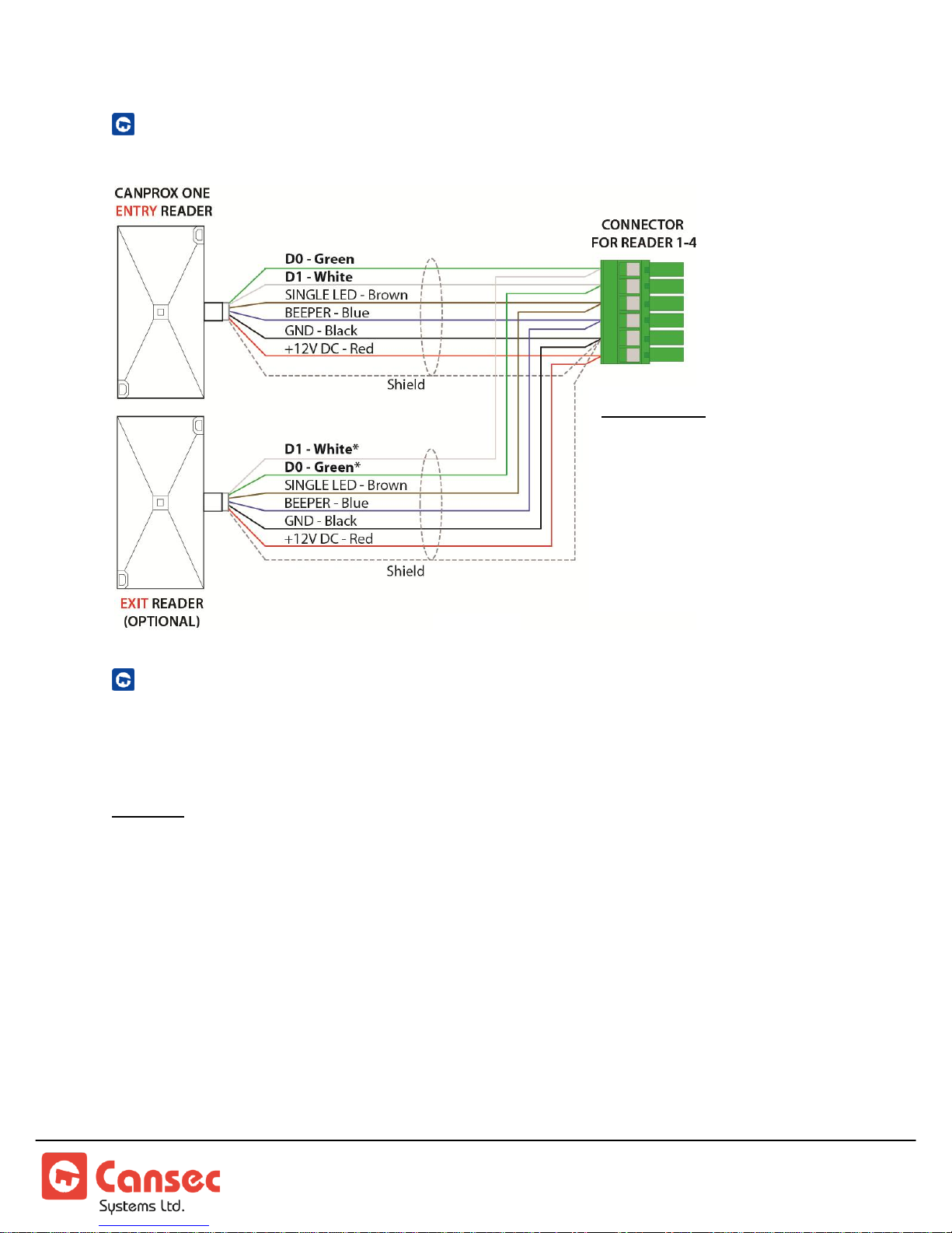
ENTRY AND EXIT READER WIRING
Exit Reader:
*D1 (White) of exit reader
connects to D0 (Green) of
entry reader.
*D0 (Green) of exit reader
connects to D1 (White) of
entry reader.
Figure 5
EXIT BUTTON AND DOOR CONTACT WIRING
The MAP1 controller can be provisioned for up to 4 doors. The following shows the
input usage for each door combination.
Caution: When moving the MSJx - MicroShunt jumpers (small and easily dropped, accuracy is
important during movement) it is advisable to set up the MAP1 Controller prior to attaching it
to a surface. It is highly recommended that the MAP1 be removed from the attached surface to
do a change of the MSJx position. See figure 6 below.
Reader 1: uses Input 1 (Door Contact/DPS) and Input 2 (RTE/REX).
Reader 2: uses Input 3 (Door Contact/DPS) and Input 4 (RTE/REX).
Reader 3: uses Input 5 (Door Contact/DPS) and Input 6 (RTE/REX).
Reader 4: uses Input 7 (Door Contact/DPS) and Input 8 (RTE/REX).
Note: Both door contact and exit button inputs have voltage present on the circuits. Only
connect dry contact devices to these inputs.
MAP1 Page 12 of 31
Installation Manual June 2018 • Rev. 1.6
Page 13
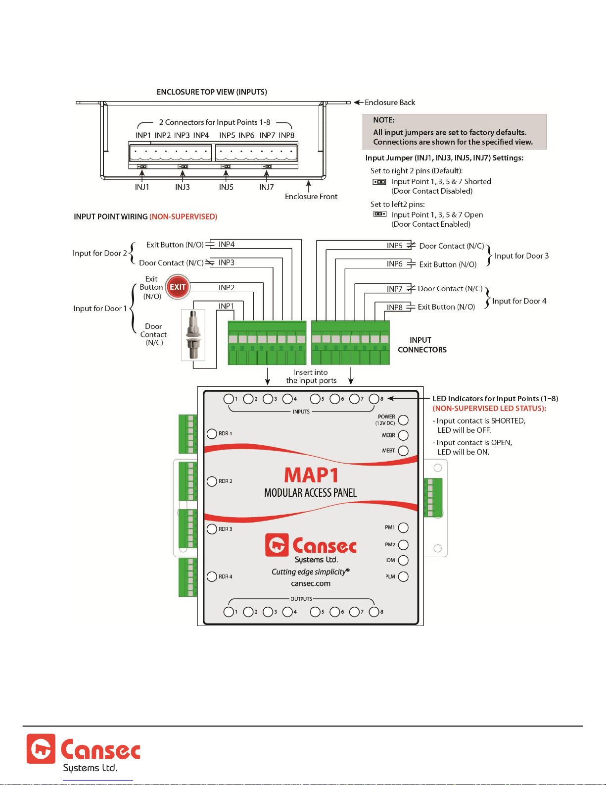
Figure 6
Non-Supervised
MAP1 Page 13 of 31
Installation Manual June 2018 • Rev. 1.6
Page 14
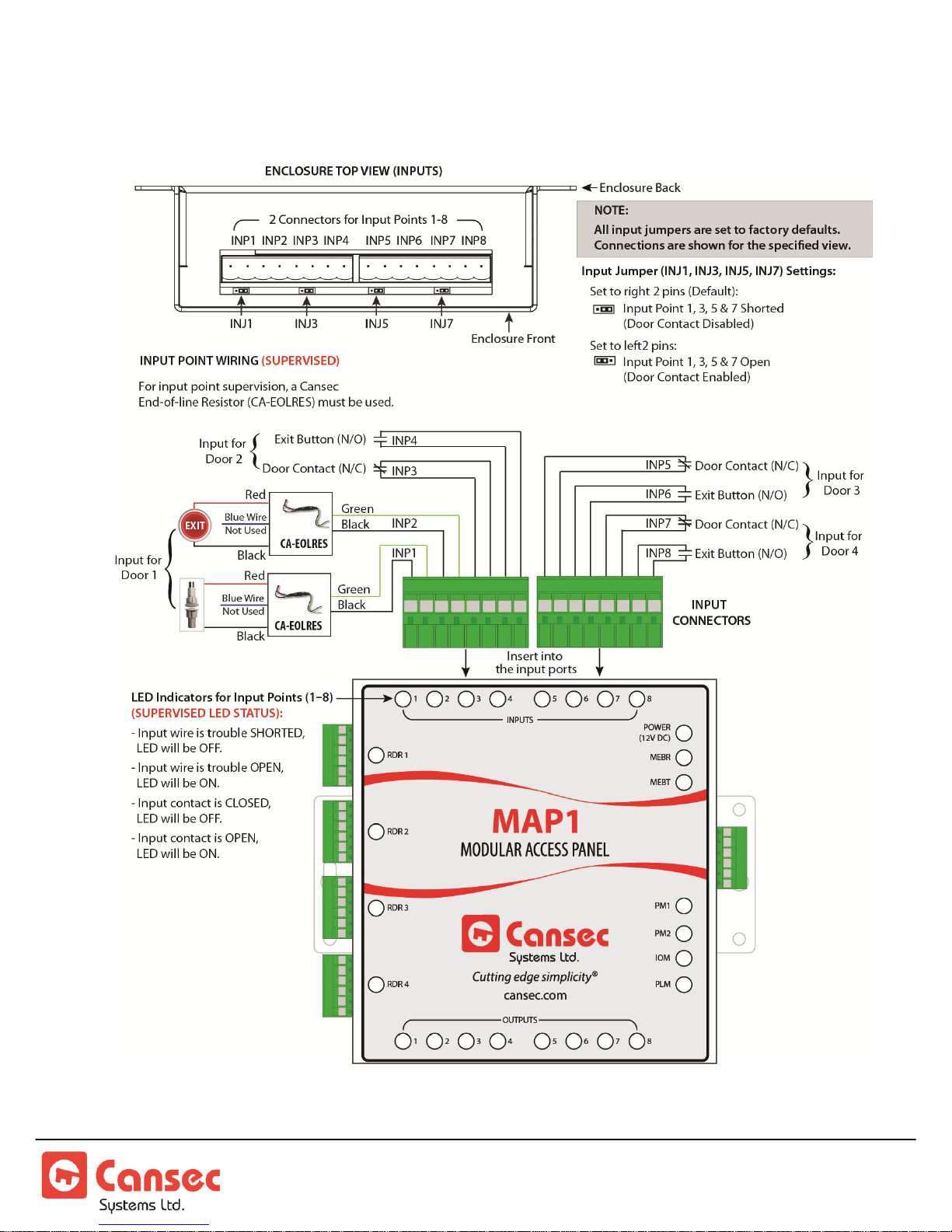
Figure 7
Supervised
MAP1 Page 14 of 31
Installation Manual June 2018 • Rev. 1.6
Page 15
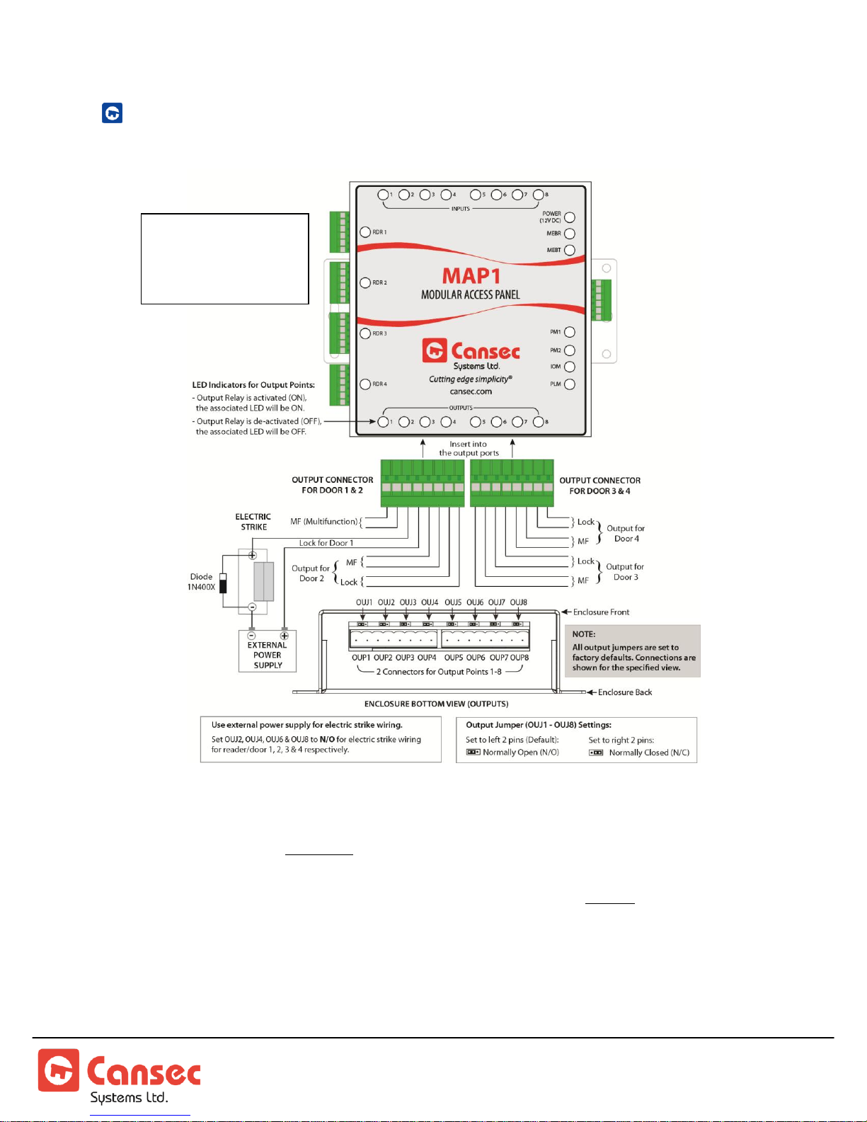
LOCK OUTPUT AND MULTI-FUNCTION RELAY WIRING
Figure 8
See Note 2 in
Appendix section for
6 Amp relay rating
Electric Strike Lock Wiring – Up To 6 Amp, 30VDC MAX
The Multi-Function (MF) relay is configured by the user through the host software.
This relay can be set to only one of the following options:
Alarm Shunt – (factory default) Shunt the alarm system before opening lock.
Door Held Open – Door has been left open.
Forced Entry – Door opened without access-granted or exit-button-press event.
Door Operator_All – Activated on all cards (Lock Opens first).
Door Operator_HC – Activated on only Handicap cards (Lock Opens first).
MAP1 Page 15 of 31
Installation Manual June 2018 • Rev. 1.6
Page 16
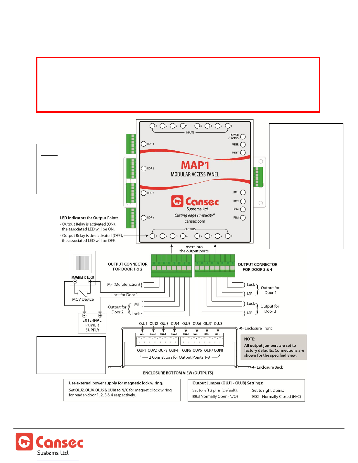
Magnetic Lock Wiring – Up To 6 Amp, 30VDC MAX
IMPORTANT: In some jurisdictions, the use of a UL approved power supply and
connection to the fire alarm system for emergency release may be required. Installers
should contact the local authority having jurisdiction to verify the specific
requirements. Also, a building permit may be required in some jurisdictions for the
installation of magnetic locks.
Figure 9
See Note 2 in
Appendix section for
6 Amp relay rating
Note: A diode can
cause slow release of
the magnetic lock. It
is better to use a
MOV device. Some
magnetic locks have
built-in MOV devices;
in that case no diode
or additional MOV is
required. Check with
magnetic lock
supplier.
Note: See Electric Strike
Lock Wiring section for
explanation of MF relay
usage.
MAP1 Page 16 of 31
Installation Manual June 2018 • Rev. 1.6
Page 17
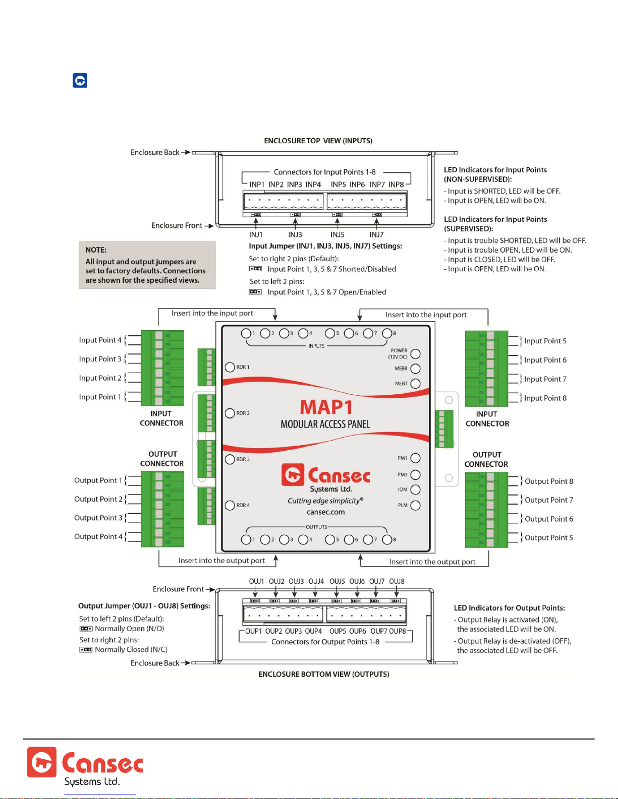
INPUT AND OUTPUT POINT WIRING
Figure 10
General Layout
MAP1 Page 17 of 31
Installation Manual June 2018 • Rev. 1.6
Page 18
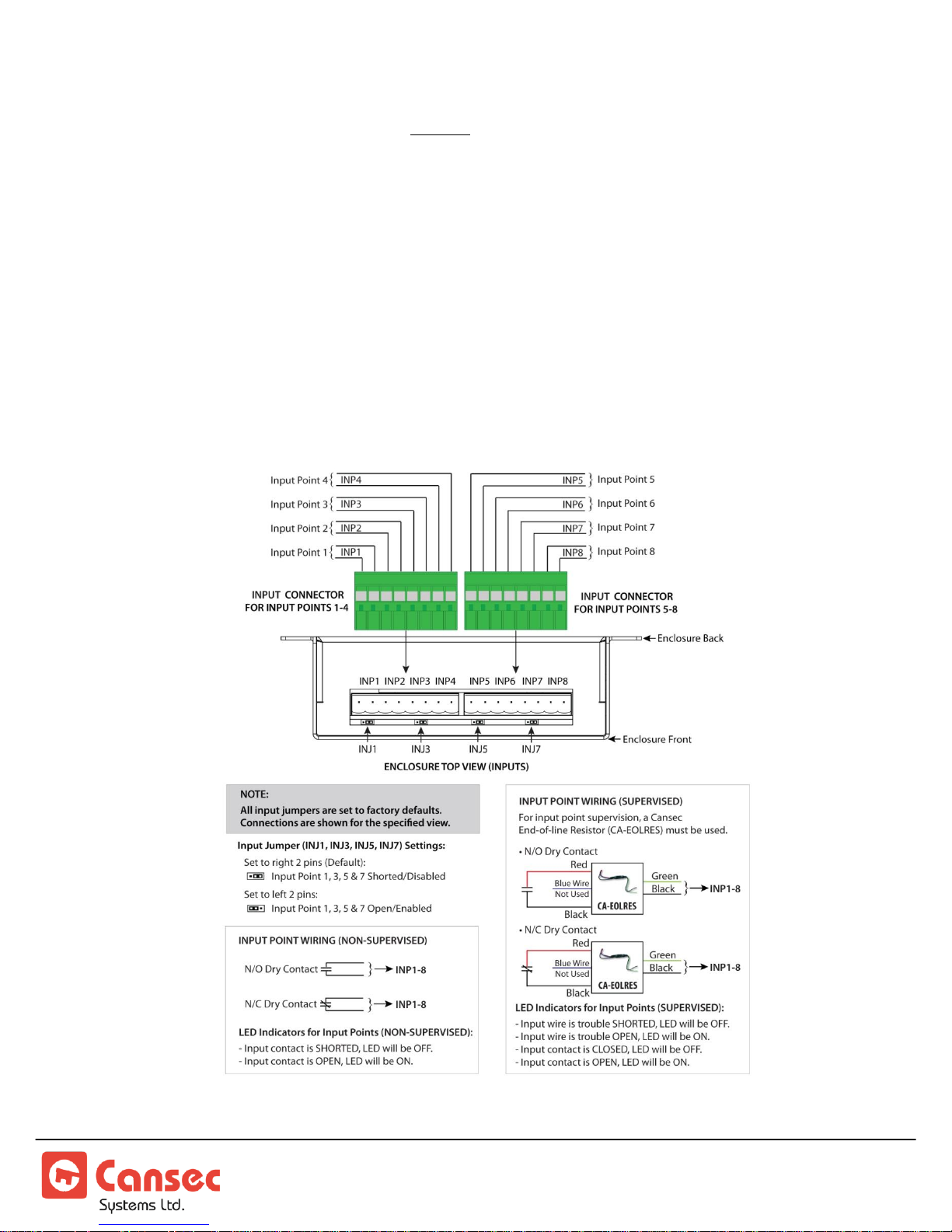
The MAP1 can be provisioned for all I/O which allows for 8 input points and 8
Figure 11
output points to be used and no door combination.
The inputs can be individually set through the host software to be supervised or nonsupervised. The default input setting is non-supervised. Supervised input points require
a Cansec CA-EOL resistor pack to be placed at the device being monitored. Supervised
input points will inform the host of 4 supervised states:
and
Trouble Low
Alarm, Secure, Trouble High
These are the same 8 input points which can be used with the door provisioning
combinations, thus devices such as the Door Contact and RTE/REX pushbutton can
used in supervised mode of operation if necessary.
Input Wiring – Supervised or Non-Supervised
MAP1 Page 18 of 31
Installation Manual June 2018 • Rev. 1.6
Page 19
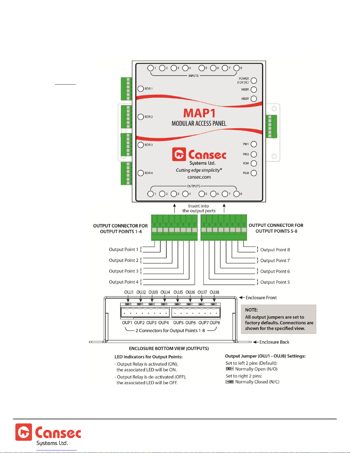
Output Wiring
Figure 12
Caution: When moving
the MSJx - MicroShunt
jumpers (small and easily
dropped, accuracy is
important during
movement) it is advisable
to set up the MAP1
Controller prior to
attaching it to a surface.
It is highly recommended
that the MAP1 be
removed from the
attached surface to do a
change of the MSJx
position.
MAP1 Page 19 of 31
Installation Manual June 2018 • Rev. 1.6
Page 20
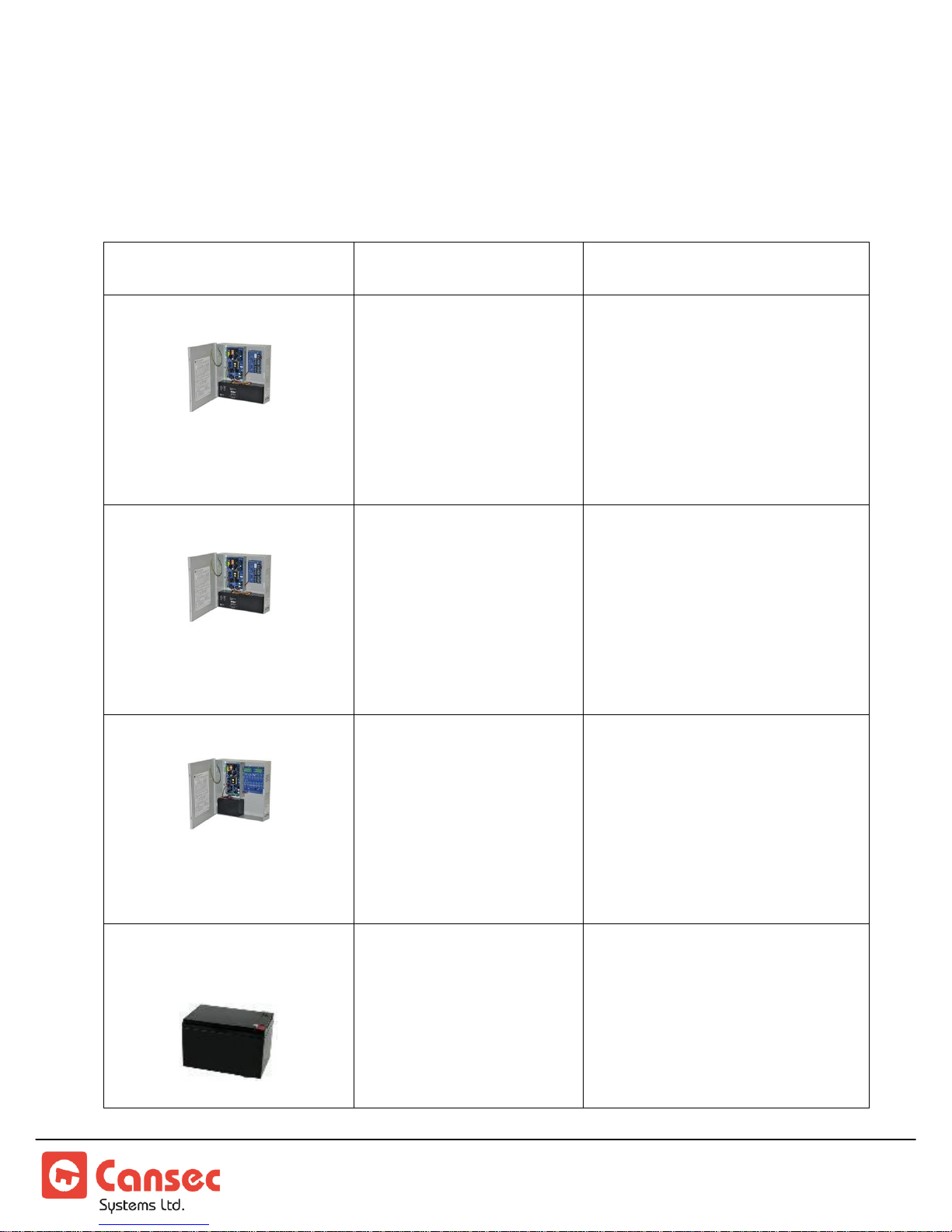
Appendix
Part Number
Dimension & Weight
H x W x D approx.
Description
CA-EFLOW4N8D
(battery not included)
Accommodates up to two
(2) 12VDC/7AH batteries.
13.5” x 13” x 3.25”
(342.9mm x 330.2mm x
82.55mm)
6.7 lbs. (3.04 kg)
12/24 VDC selectable output,
4 Amp Enclosure Style Power
Supply with Backup Battery
Charger. Eight individual class
2 rated power limited outputs
rated at 2 Amp. Input 120
VAC, 60 Hz, 3.5 Amp. UL
listed.
CA-EFLOW6N8D
(battery not included)
Accommodates up to two
(2) 12VDC/7AH batteries.
13.5” x 13” x 3.25”
(342.9mm x 330.2mm x
82.55mm)
6.65 lbs. (3.02 kg)
12/24 VDC selectable output,
6 Amp Enclosure Style Power
Supply with Backup Battery
Charger. Eight individual
Class 2 rated power limited
outputs rated at 2 Amp per
output. Input 120 VAC, 60
Hz, 3.5 Amp. UL listed.
CA-EFLOW102N16D
(battery not included)
Accommodates up to two
(2) 12VDC/7AH batteries.
13.5” x 13” x 3.25”
(342.9mm x 330.2mm x
82.55mm)
6.85 lbs. (3.11 kg)
12 VDC, 10 Amp Enclosure
Style Power Supply with
Backup Battery Charger.
Sixteen individual Class 2
rated power limited outputs
rated at 2 Amp per output.
Input 120 VAC, 60 Hz, 3.5
Amp. UL listed.
PA-SLP003
3.63” x 5.88” x 2.5”
(92.20mm x 149.35mm
x 63.50mm)
5.00 lbs (2.27 kg)
Backup Battery 12 VDC 7
Amp Hour. Provides hours of
backup power for above power
supplies.
Note 1: Suggested Power Supplies & Backup Battery
MAP1 Page 20 of 31
Installation Manual June 2018 • Rev. 1.6
Page 21

Note 2: 6 Amp Relay Rating
IMPORTANT: In some jurisdictions, the use of a UL approved power supply and
connection to the fire alarm system for emergency release may be required. Installers
should contact the local authority having jurisdiction to verify the specific
requirements. Also, a building permit may be required in some jurisdictions for the
installation of magnetic locks.
Note: PM1 and PM2
LED will occasionally
and rapidly toggle ON
and OFF when host
communication is in
progress.
Maximum current that can be switched reliably when connected to a ‘non-inductive load’ up to
30VDC. Electric strikes and magnetic locks are considered ‘inductive loads’. It is important to
have diode or MOV attached at the locking device to remove the CEMF pulse that is generated
when switching an ‘inductive load’. It is advisable to use a 50% switch factor or 3 amps as the
maximum switching current for longer relay life. An external relay should be used on larger
voltage and current requirements.
MAP1 SYSTEM INDICATORS
POWER LED: ON indicates 12 volts DC is connected.
MEBR LED, MEBT LED: For future use.
First Access Mode:
Mode indicator: MAP1 emits 1 beep after powered up.
PM1 LED: ON, PM2 LED: OFF
Webster Mode:
Mode indicator: MAP1 emits 2 beeps after powered up.
PM1 LED: ON, PM2 LED: OFF
Cloud Lock Mode:
Mode indicator: MAP1 emits 3 beeps after powered up.
PM1 LED: ON, PM2 LED: OFF
IOM LED: Flashing RED – IOM (Input Output Module) is in normal operation.
PLM LED:
Flashing GREEN – PLM (Panel Logic Module) is waiting for a connection from
the host via Ethernet.
ON GREEN – PLM (Panel Logic Module) is connected to a host via Ethernet.
MAP1 Page 21 of 31
Installation Manual June 2018 • Rev. 1.6
Page 22
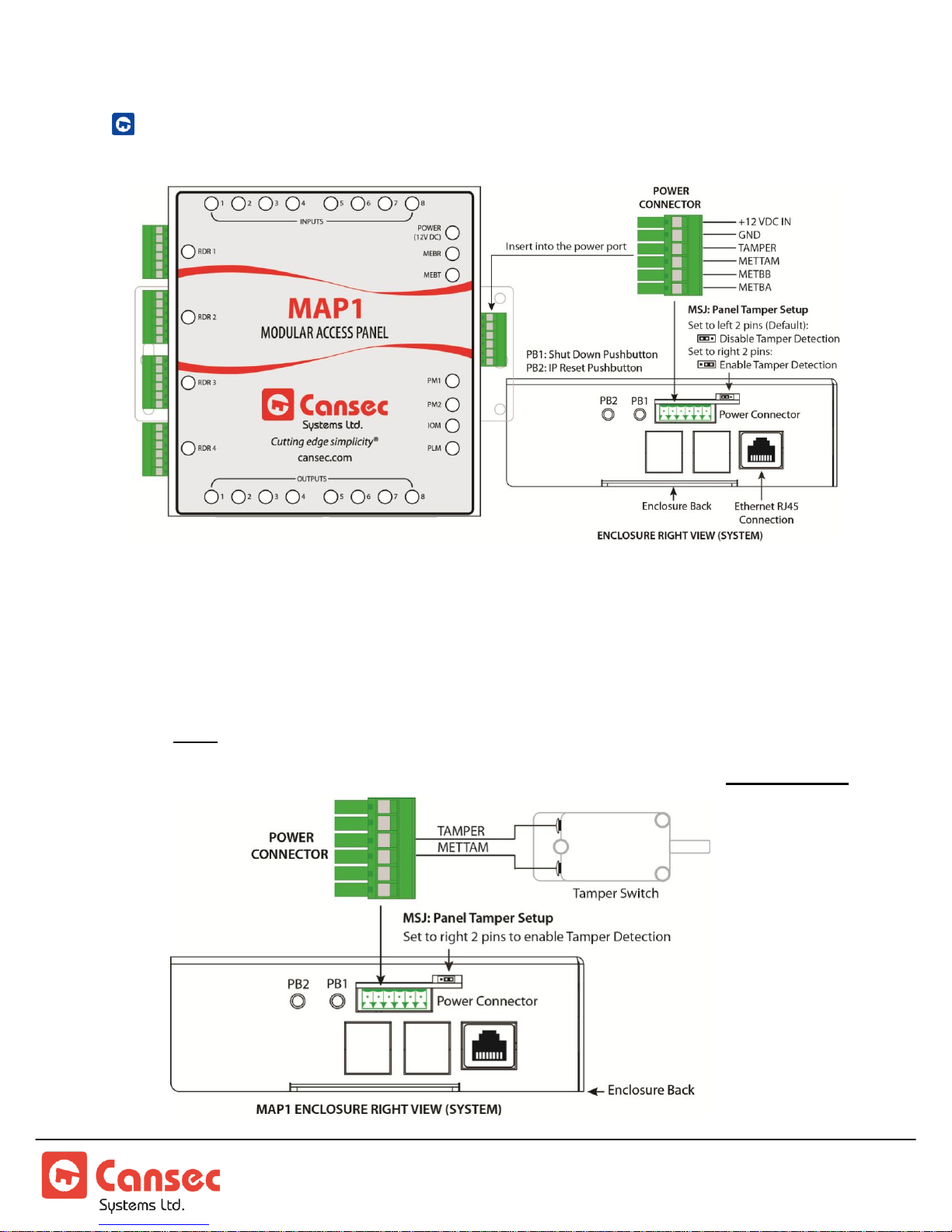
POWER CONNECTOR
Figure 13
Factory default:
The Tamper jumper
is set to disabled.
To activate the
Panel Tamper move
jumper to the right
2 pins. Connect the
switch between
TAMPER and the
METTAM on the
connector.
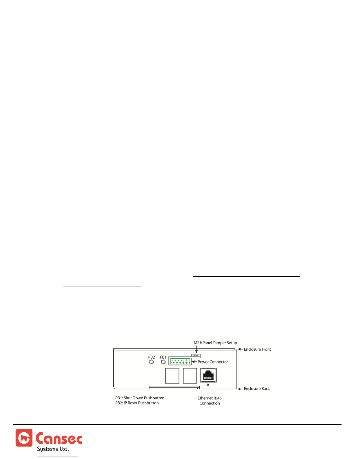
Figure 14
Connections:
METBA and METBB are for future use. The Shield from METBA and METBB
TAMPER allows for the connection of an external Enclosure Tamper Switch.
wire would be connected to METTAM.
Note: The MAP1 has a Tamper MSJx-MicroShunt jumper to the right of this power
connector.
MAP1 Page 22 of 31
Installation Manual June 2018 • Rev. 1.6
Page 23

GND – this is the 12 volt power supply ground.
12VDC IN – Power for MAP1. 12 volt DC battery backed up power supply.
This is the power for the MAP1 and readers attached.
PB1 – SHUTDOWN BUTTON
As the MAP1 contains a mini computer, a proper system shutdown is nesscessary to
prevent data corruption. DO NOT simply unplug the power connector. To shut
down follow this procedure:
1. Use a paper clip or a small screw driver, press and hold (4 to 8 seconds) the PB1
pushbutton until the PLM STATUS LED on the front of the enclosure begins a
rapid green ON/OFF flash.
2. Release the pushbutton. The system will start a proper shutdown. This will take
15 to 20 seconds.
3. Wait untill all LEDs (except power) are turned off by the system. Then remove
the Power Connector.
4. If the Shutdown does not occur, try the procedure again. If it still does not
respond correctly as described above, a system fault has occurred. It will be
necessary to unplug the Power connector and re-insert it after 10 seconds.
PB2 – IP RESET BUTTON AND STATIC IP ADDRESS CONFIGURATION
Note: The new panel is factory set to acquire an IP address automatically (DHCP). If the IP
address has been changed to static address by an installer but now unknown or
forgotten and needs to be reset, follow the instructions below.
Static IP address is recommended only for Webster mode. Leave it to
obtain IP address automatically for other modes
MAP1 Page 23 of 31
Installation Manual June 2018 • Rev. 1.6
Alternatively, see USB IP Configuration Tool section for configuring IP
Address using a USB flash drive.
.
Page 24
1. Press and hold (4 to 8 seconds) the IP Reset PB2 pushbutton. Wait until the
Figure 15
Figure 16
internal MAP1 beeper sounds then release the button. Beeper stops sounding.
2. The system will reboot. This will take 20 to 45 seconds after which the
controller will reset all of its configurations to factory default with DHCP
enabled. Existing database will not be reset or erased.
Note: The end of the reboot cycle is indicated by a MAP1 turning back on the associated
system LEDs and at the end it will emit a series of beeps to indicate its mode e.g.
Access, Cloud Lock
or
Webster
.
First
3. Plug the MAP1 to the network with a DHCP server available.
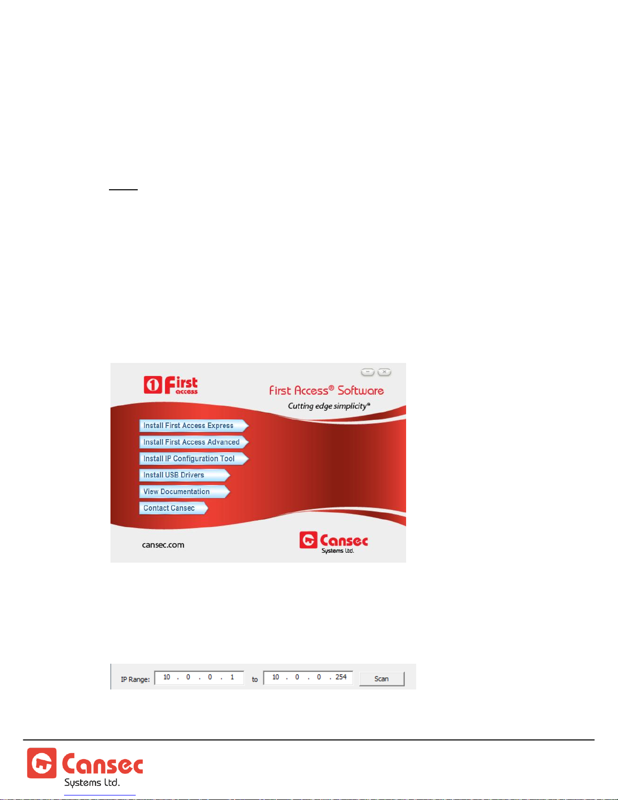
4. Install and launch MAP1 IP Configuration Tool from your computer. This tool
is available from the First Access software installation package, but is also
available as its own separate installation package which can be downloaded from
www.cansec.com/downloads.
5. In most cases, the IP Configuration Tool will detect and display the default IP
address range ready to be scanned. However, the IP address range can be
manually modified accordingly.
6. Click Scan to scan the network for all possible connected MAP1 panels.
MAP1 Page 24 of 31
Installation Manual June 2018 • Rev. 1.6
Page 25
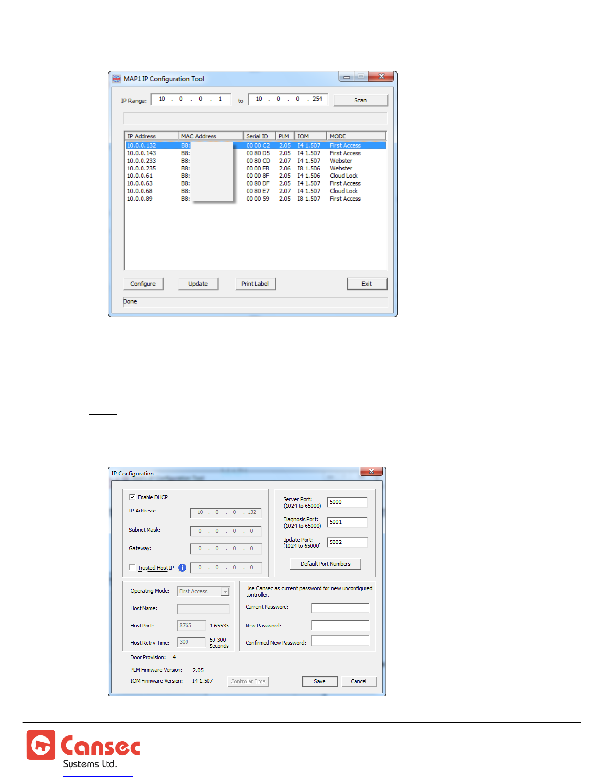
Figure 17
Figure 18
7. Double click on one of the detected panels or select it and click Configure.
8. Unselect Enable DHCP. Consult with IT personnel and enter the IP address,
Subnet Mask, Gateway IP Address and Port numbers.
Note: The optional Trusted Host IP (see Figure 18) instructs the panel to accept data
connection only from the host computer where the First Access software is installed.
Other connections for diagnosis and updating are not limited by this Trusted Host IP.
MAP1 Page 25 of 31
Installation Manual June 2018 • Rev. 1.6
Page 26
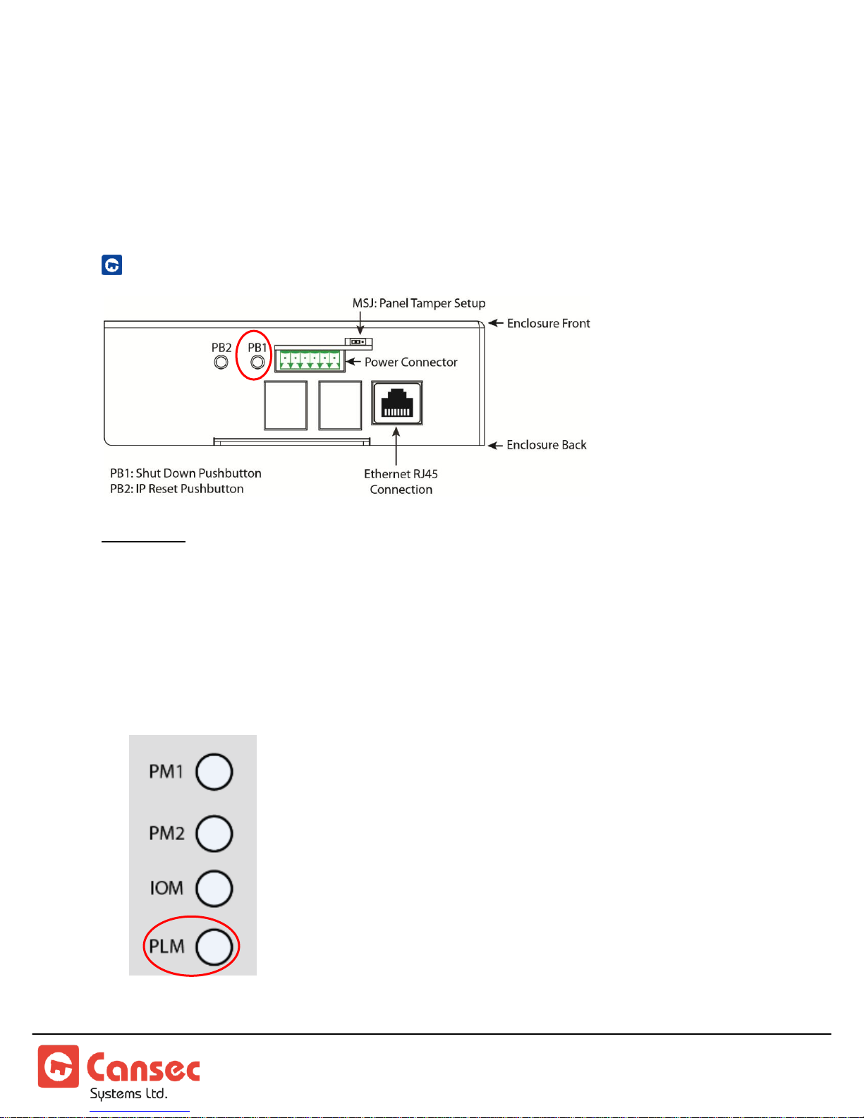
9. The factory default or current password for a new unconfigured MAP1 panel is
Figure 19
Figure 20
Cansec. The password must be changed to something else other than Cansec.
10. Click Save. The panel saves the new settings and reboots for the settings to take
effect.
USB IP CONFIGURATION TOOL
Important: Shutdown Push Button (PB1) must be used to avoid data corruption on the MAP1
controller.
1. If the MAP1 controller is powered on, press and hold the PB1 button for a period
of 5 to 8 seconds and proceed to step 2. Otherwise, proceed to step 4.
2. When the PLM LED on the front of the MAP1 controller begins a rapid flash,
release the Shutdown PB1 button.
MAP1 Page 26 of 31
Installation Manual June 2018 • Rev. 1.6
Page 27
3. Wait until the MAP1 does a complete shutdown, indicated by all MAP1 LEDs
Figure 21
going to the OFF state (except the Power LED), and unplug the power connector.
4. Insert a FAT32 formatted USB flash drive into an available USB connector on the
MAP1 controller.
5. Insert the power connector into the MAP1 controller. The unit will begin the
power up sequence which takes about 30 to 40 seconds. When complete, the
MAP1 controller will emit a series of beeps to indicate its mode e.g. First Access,
Cloud Lock or Webster.
6. Remove the USB flash drive from the MAP1 controller.
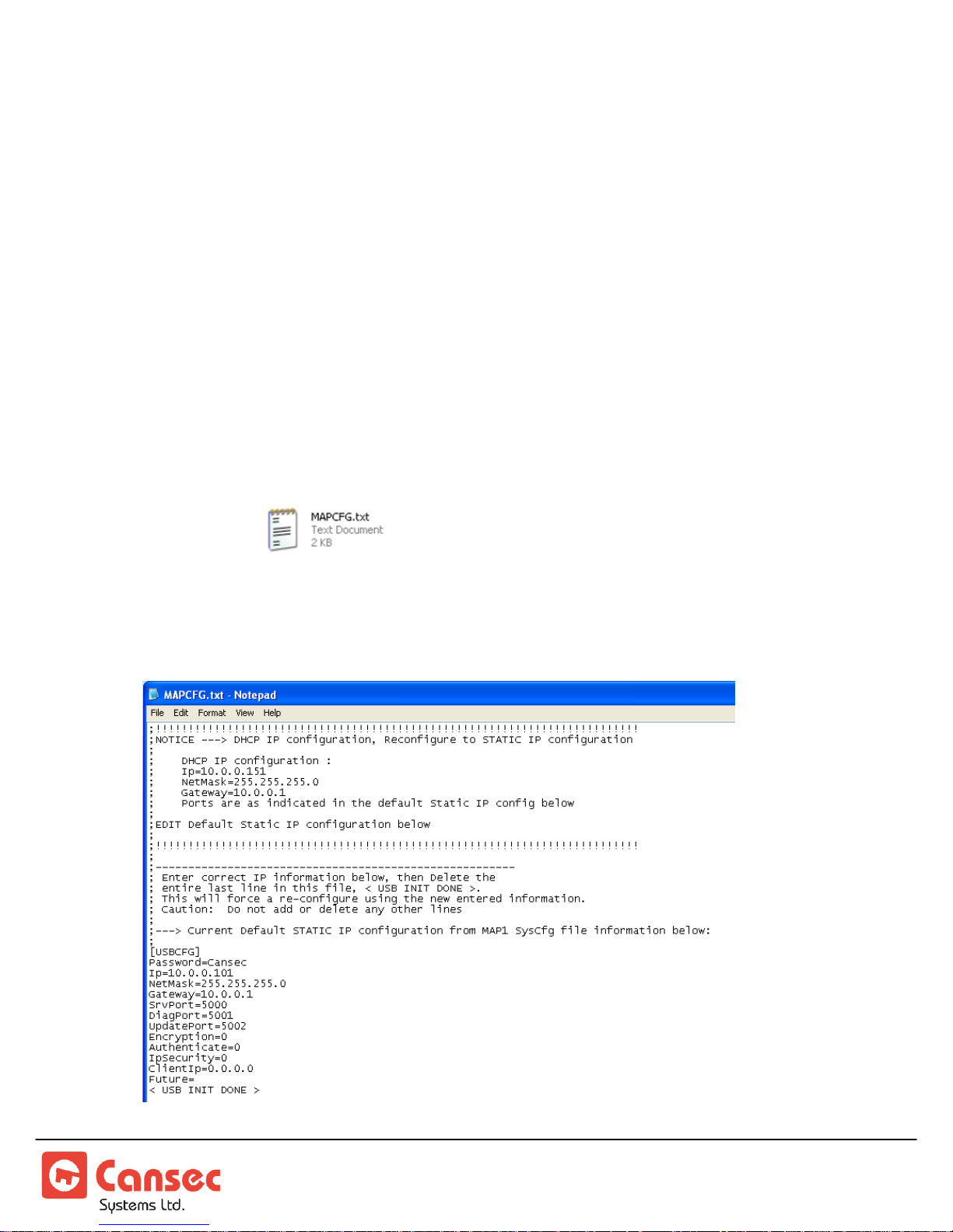
7. Insert the flash drive into a USB port on a computer. When ready, launch
Windows Explorer or File Explorer. Access the USB drive and edit the file named
MAPCFG.txt created by the MAP1 controller during boot-up
sequence. If the file is not present, repeat from step 1. Otherwise proceed to step 8.
8. A similar file will be displayed when opened in Notepad.
MAP1 Page 27 of 31
Installation Manual June 2018 • Rev. 1.6
Page 28

Key Section & Name
Value
Description
[USBCFG]
[USBCFG]
Key section –
DO NOT
change
Password
Cansec
Factory default password. Please
modify to an appropriate password of
your choice other than the default
password.
IP
10.0.0.101
Factory default IP address. Please
Specify the IP address of the host
computer having the
First Access
Express
software installed.
Netmask
255.255.255.0
Factory default subnet mask. Please
specify the subnet mask where the
host computer is connected to.
Gateway
10.0.0.1
Factory default gateway. Please
specify the gateway where the host
computer is connected to.
SrvPort
5000
Factory default server port. You may
change it or leave it as default.
DiagPort
5001
Factory default diagnostic port. You
may change it or leave it as default.
UpdatePort
5002
Factory default update port. You may
change it or leave it as default.
Encryption
0
For future use only.
Authenticate
0
For future use only.
IpSecurity
0
Specify if trusted host is enabled or
disabled. 1=enabled, 0=disabled
ClientIp
0.0.0.0
The IP address of the host computer
having the
First Access Express
software installed. If IpSecurity is
enabled and ClientIp has a valid IP
address specified then the MAP1
controller accepts data connection
(SrvPort 5000) from only this host
computer. Other connections on
DiagPort 5001 and UpdatePort
5002 are not affected by this setting.
Future
blank
For future use only.
MAP1 Page 28 of 31
Installation Manual June 2018 • Rev. 1.6
Page 29
< USB INIT DONE >
< USB INIT DONE >
Please remove this line after this file
has been correctly modified. The
MAP1 controller reads parameters in
this file during boot up sequence and
configures the IP address accordingly
after which it will write <USB INIT
DONE> to indicate that the
initialization has been done.
Figure 22
9. Obtain all IP address information from IT personnel and modify the file
accordingly. Remove the line <USB INIT DONE> and save the file before removing
it from your computer.
10. Repeat from step 1 to step 6 then proceed to step 11.
11. Insert the flash drive into a USB port on a computer. When ready, launch
Windows Explorer or File Explorer. Access the USB drive and check if there is an
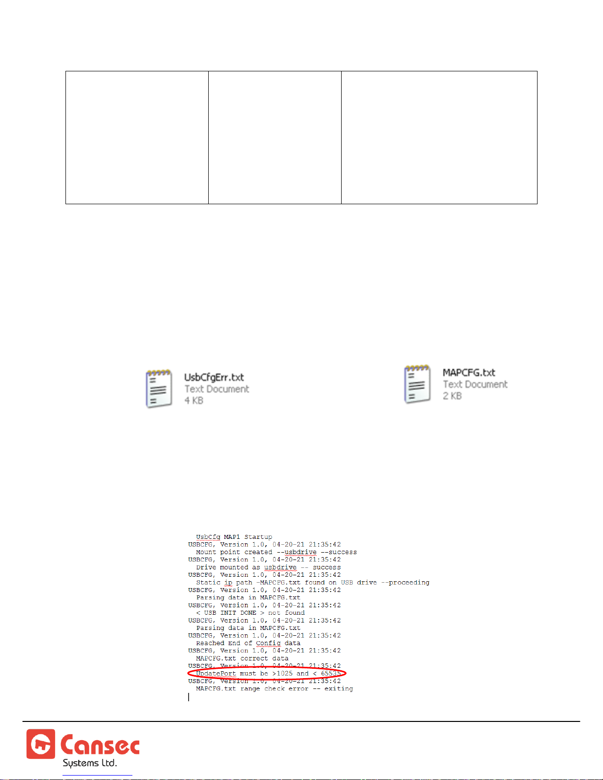
error file present along with the file .
12. If no error file is present skip this step and proceed to step 13. Otherwise edit the
error file and review the errors indicated. Correct the errors in the MAPCFG.txt
accordingly and save it before removing it from the computer. Repeat step 1 to 6
then proceed to step 11. See sample error file below.
MAP1 Page 29 of 31
Installation Manual June 2018 • Rev. 1.6
Page 30

13. If no error file is present, it’s recommended that the file MAPCFG.txt
be reviewed to ensure that the line <USB INIT DONE> has
been written by the MAP1 controller indicating that the IP configuration has been
successfully saved and initialized.
14. A file named SysInf.txt is also present. This file contains critical information if
debugging is required. If this file is not present it is recommended that the
controller be updated with the latest firmware.
FORCED ENTRY OUTPUT
To monitor forced-entry or door-held-open alarm conditions, connect a Normally
Closed door contact switch or sensor to the door contact input. The (MF)
multifunction relay, when configured as
forced open without either an access-granted or an exit-button event. A message will be
transmitted to the host software if the panel is online.
Forced Entry
, will be activated if the door is
DOOR HELD OPEN OUTPUT
The (MF) multifunction relay, when configured as
if the lock is unlocked and the door is held open longer than the permitted door-heldopen time programmed from the host software. The reader beeps to notify the user by
first generating a pre-alert beep followed by a solid beep, then a message is also
transmitted to the host software if the panel is online.
Door Held Open
, will be activated
ALARM SHUNT OUTPUT
The (MF) multifunction relay is factory configured as
granted or an exit button event occurs, the alarm shunt output relay is activated first
followed by the lock output relay. The relay can be used to bypass an external alarm
point. When an access-granted or an exit button event is complete, the lock output is
turned off followed by the Alarm Shunt output after a short delay. If a door contact is
used then Alarm Shunt output is turned off shortly after the door contact is closed.
Alarm Shunt
. When an access-
MAP1 Page 30 of 31
Installation Manual June 2018 • Rev. 1.6
Page 31
DOOR OPERATOR OUTPUT – ALL CARDS
The (MF) multifunction relay, when configured as
Door Operator_All
, will be
activated by all cards and by exit button press. The lock relay will be activated first
followed by a one second pulse on this MF relay which is used to trigger the door
operator.
DOOR OPERATOR OUTPUT – HANDICAP CARDS ONLY
The (MF) multifunction relay, when configured as
activated by cards designated as handicap and by exit button press. The lock relay will
be activated first followed by a one second pulse on this MF relay which is used to
trigger the door operator.
© Cansec Systems Ltd., 2018 All rights reserved
Door Operator_HC
, will only be
MAP1 Page 31 of 31
Installation Manual June 2018 • Rev. 1.6
 Loading...