

Page 1

Cutting edge simplicity
First Access
OPERATOR GUIDE
October 2020
Page 2

Table of Contents
Introduction ...........................................................................................................................................................4
PC Requirements ................................................................................................................................................5
Step 1. Software Installation ..........................................................................................................................5
Step 2. Host Server Definition .......................................................................................................................9
Step 3. Panel and Reader Definition ......................................................................................................... 17
Add Panel ............................................................................................................................................. 17
Add Reader .......................................................................................................................................... 18
Define Auxiliary Input Point .............................................................................................................. 25
Define Auxiliary Output Point ........................................................................................................... 26
Edit and Delete Panel ........................................................................................................................ 27
Reader Status ..................................................................................................................................... 27
Reader Commands, Scheduled Commands, Triggers, Counters........................................... 28
Reader Events .................................................................................................................................... 40
Alarm Notifications ............................................................................................................................. 42
Alarm Queue ....................................................................................................................................... 49
Application Windows ......................................................................................................................... 50
Input and Output Commands .......................................................................................................... 50
Step 4. Schedules, Profiles, Users and Operators ............................................................................. 52
Access Schedules .............................................................................................................................. 52
Unlock Schedules ............................................................................................................................... 53
Shunt Schedules ................................................................................................................................ 55
Output Schedules ............................................................................................................................... 56
Holiday Schedules ............................................................................................................................. 57
User Profiles ........................................................................................................................................ 59
Add Cardholders and Card Groups................................................................................................ 61
Search, Edit and Delete Cardholder .............................................................................................. 66
Operator Profiles ................................................................................................................................ 69
Cardholder and Credential Report ................................................................................................. 71
Step 5. History and Audit Report ............................................................................................................... 72
Configure History Retention ............................................................................................................. 72
On-board Audit Event Storage ........................................................................................................ 72
View Audit History .............................................................................................................................. 73
Elevator ................................................................................................................................................................. 75
Floor Groups, Access Groups and Floor-Unlock Schedule ...................................................... 75
Add Elevator Panel ............................................................................................................................ 77
Manage Elevator Floors .................................................................................................................... 78
Appendix .............................................................................................................................................................. 81
Database Backup Utility .................................................................................................................... 81
Bulk Credential Load Utility .............................................................................................................. 82
FA Access View .................................................................................................................................. 83
First Access Page 2 of 88
Operator Guide October 2020 • Rev. 2.3
Page 3

First Access Import Utility ................................................................................................................. 84
Copyright © 2020 Cansec Systems, Ltd.
SQL Server Connection Configuration Utility ............................................................................... 86
Email Diagnostics ............................................................................................................................... 87
Daily Synchronization ........................................................................................................................ 88
CAUTION: EMERGENCY LOCKDOWN
Emergency lockdown functions must operate totally independent of the access control
system and must not rely on operation of card readers, access control panels,
communications networks, communications devices or host software. Cansec accepts no
responsibility for direct or consequential damages resulting from the failure of emergency
lockdown functions which are dependant in any way on the operation of card readers,
access control panels, communications networks, communications devices or host software.
First Access Page 3 of 88
Operator Guide October 2020 • Rev. 2.3
Page 4

Introduction
Key Features
First Access software is extremely cost-effective and easy to use to manage the MAP1,
MAP2 and MAPMINI door controllers. The MAP2 panel can be provisioned as door
controller or as elevator controller. There are two editions of the software First Access
Express with 2-client concurrent connections, and First Access Advanced with 10-client
concurrent connections. Both versions support up to 450 controllers. The final door
capacity is dependent on the number and type of controllers. If all MAP1s are used and
provisioned for 4 readers the door count is 1800. If all MAP2s are used and provisioned
for 8 readers the door count is 3600. If only MAPMINIs are used the door count is 450.
The number of users for FA Express is 5000 and for FA Advanced it is 100,000. The
software also supports elevator control using MAP2 controller provisioned as elevator
controller. The MAP2 panel can be provisioned as a 16-floor elevator controller. However,
with the optional add-on H1000 panels the MAP2 controller can be provisioned to control
32 or 48 or a maximum of 64 floors. The controllers support scheduled commands,
triggers, timed anti-passback, local anti-passback, and double-swipe privilege. It also
supports up to 64 bit Wiegand-output reader technologies such as proximity, keypad, and
biometric.
All programming changes and commands from the software are instantly transmitted to all
door controllers. The controller stores all cardholder data in non-volatile memory to
ensure continued operation and security in the event that communication to the host PC
is lost. Reader events are automatically transmitted to the PC in real time and stored on
the hard drive for viewing and report generation.
Up to 100,000 cardholder/user capacity
Up to 1024 reader capacity
Up to 10 First Access clients
Controls up to 64-floor elevator
Real time communications
Programmable access profiles and holidays
Built-in Ethernet port for software communication
Automatic door unlock schedules
Alarms for forced entry/door held open conditions
Timed and local anti-passback
Double-swipe privilege per user per door
Optional input/output points
Scheduled commands
On-board triggers and counters
Email notification
Uses Microsoft SQL database
First Access Page 4 of 88
Operator Guide October 2020 • Rev. 2.3
Page 5
PC Requirements
Important: Microsoft SQL database must be backed
up regularly. See Appendix section for
more information.
All 32 and 64 bit versions of the following Windows Operating Systems: Windows 7, 8,
10, Windows Server 2008, 2012, 2016 and Windows 2019.
See Microsoft’s web site for CPU, RAM and disk space requirements for the
aforementioned operating systems, and for SQL Server 2014 requirements:
https://msdn.microsoft.com/en-us/library/ms143506%28v=sql.120%29.aspx
CD/DVD-ROM drive
USB port and USB thumb drive
Network adapter
Step 1. Software Installation
Important: If this is the server, consult your computer administrator to configure a firewall rule to
allow incoming TCP traffic on port 5005 only if additional First Access clients,
installed on another workstation, connecting to this server. Up to 2 clients are allowed
for
First Access Express
Advanced
1. Log on to the computer with an administrative account.
2. Download First Access software from www.cansec.com/downloads.
3. Unzip and open the folder First Access.
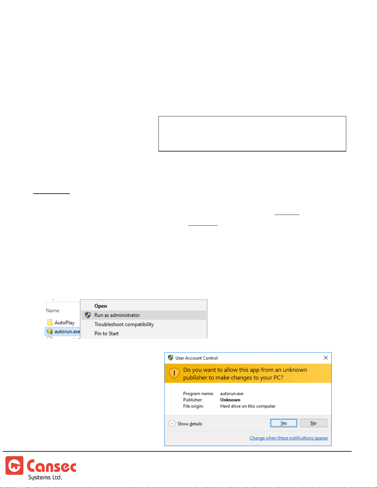
4. Right click on autorun.exe and select Run as administrator.
.
and up to 10 clients are allowed for
First Access
5. When prompted, select Yes to
continue.
First Access Page 5 of 88
Operator Guide October 2020 • Rev. 2.3
Page 6
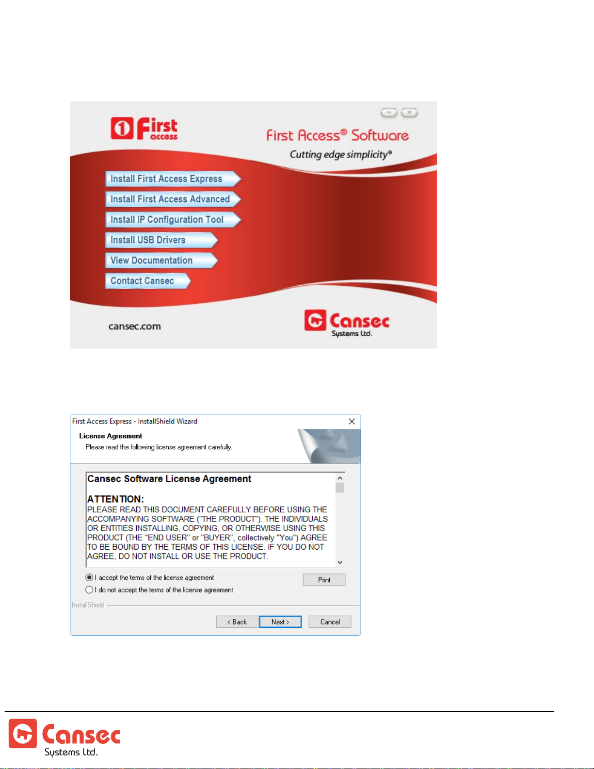
6. If you have purchased the advanced edition then select Install First Access Advanced.
Otherwise select Install First Access Express. When prompted select Next to continue.
7. Read and accept the terms of the license agreement then select Next to continue. Select
Cancel otherwise.
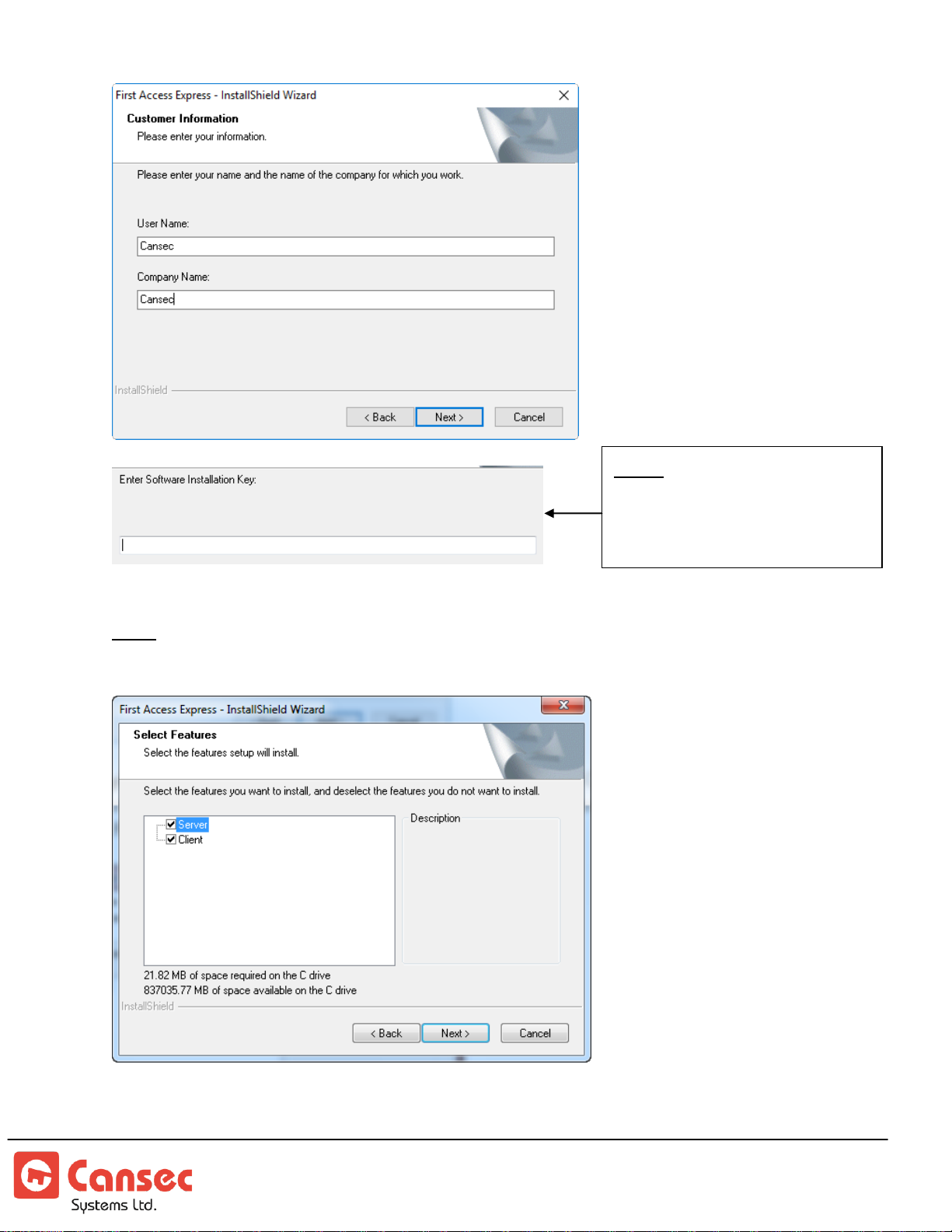
8. Enter User Name and Company Name and select Next to continue.
First Access Page 6 of 88
Operator Guide October 2020 • Rev. 2.3
Page 7
Note: Applicable to
First
Access Advanced
only.
Software key must be purchased
from Cansec dealer.
9. Select the features you wish to install and click Next to continue.
Note: For the main computer hosting the database, select both Server and Client. For additional
computers connecting to the main computer, select just Client.
First Access Page 7 of 88
Operator Guide October 2020 • Rev. 2.3
Page 8
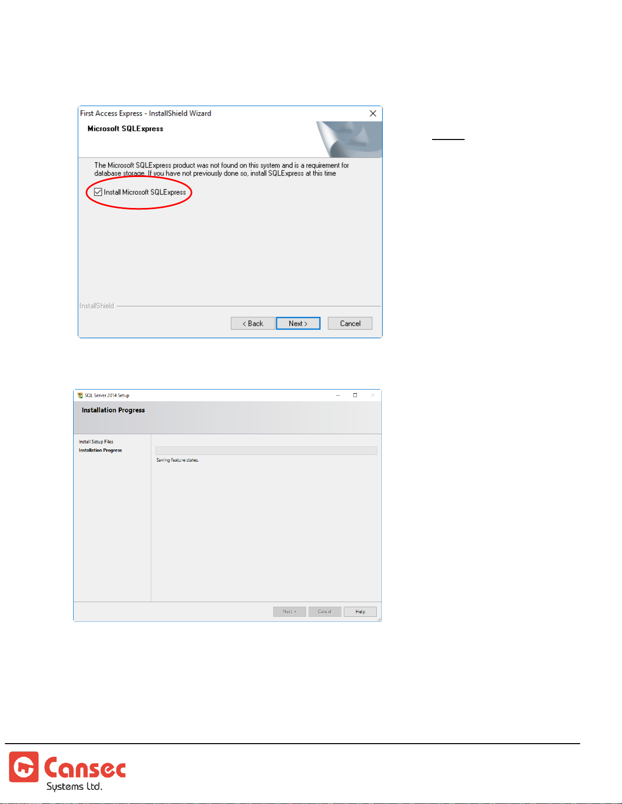
10. If SQL Express is not installed on this computer, you will be prompted to install it.
Note: If you
wish to use your
own SQL server
elsewhere then
unselect
Install
Microsoft SQL
Express
. Select
Next
to skip
Microsoft SQL
Express.
Select Next to continue.
11. Wait for the SQL Express Installation to complete.
12. After SQL installation has finished select Install to install First Access software, and at
the end of the process select Finish to complete the installation.
First Access Page 8 of 88
Operator Guide October 2020 • Rev. 2.3
Page 9
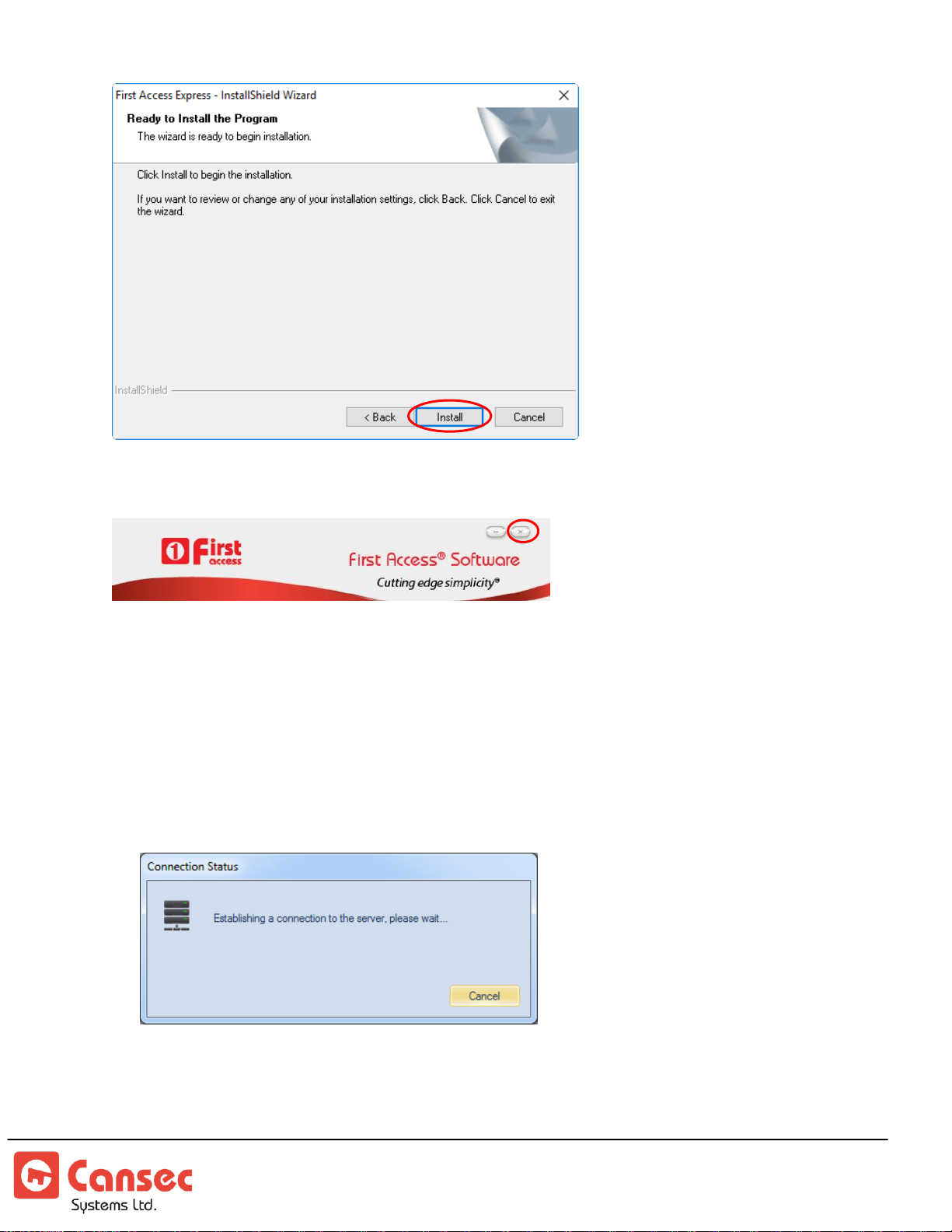
13. Select the X button on the top right corner to exit the Auto Play Installation Package.
Step 2. Host Server Definition
This section describes the initial steps to configure the First Access system. These steps are
typically done by the installation company or system administrator.
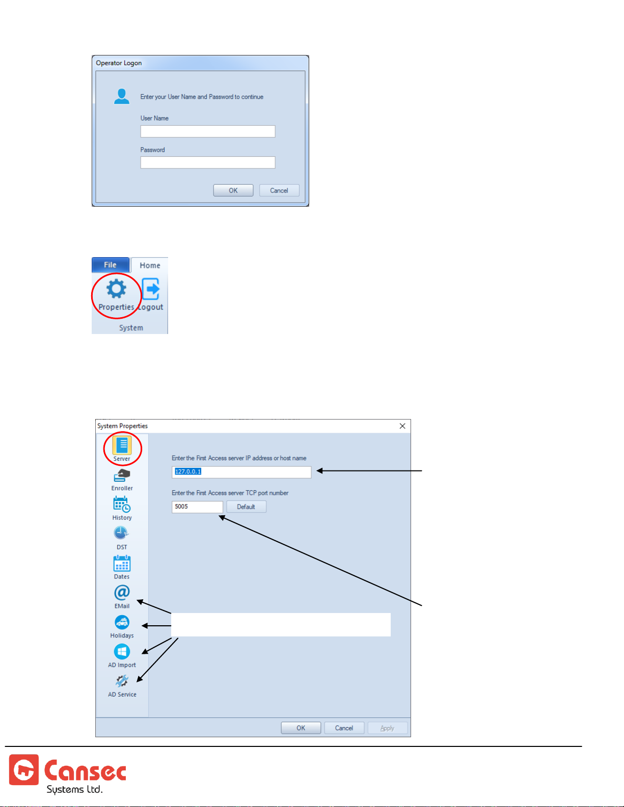
1. Launch First Access software from the shortcut on the desktop or from the Start
menu of Windows.
2. Use the default admin for both User Name and Password to logon
First Access Page 9 of 88
Operator Guide October 2020 • Rev. 2.3
Page 10
Available in First Access Advanced only
First Access client
installed on another
workstation requires the
IP address or the host
name of the computer
hosting the First Access
server.
The computer hosting
the First Access server
must have the firewall
rule configured to allow
incoming TCP traffic
on port 5005 in order
for First Access clients
installed on other
workstations to
connect. However, no
firewall rule is required
if there are no
connections from other
3. Select Properties from the main menu
4. Enter the IP address of the computer where First Access Server software is installed.
If the First Access Server is on the same computer as the First Access Client then
leave it as default with IP Address 127.0.0.1 and Port 5005.
First Access Page 10 of 88
Operator Guide October 2020 • Rev. 2.3
Page 11
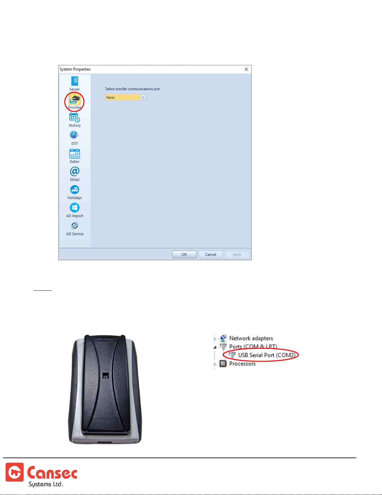
5. If a credential enroller is purchased and used, select the communication port
Credential Enroller
(USB Cable)
Communication Port
(USB Serial Port)
number to which it is connected. Otherwise skip this step.
Note: The communication port can be found in Windows’ Device Manager. See example below
showing COM2. Select
None
if no card enroller is used.
First Access Page 11 of 88
Operator Guide October 2020 • Rev. 2.3
Page 12
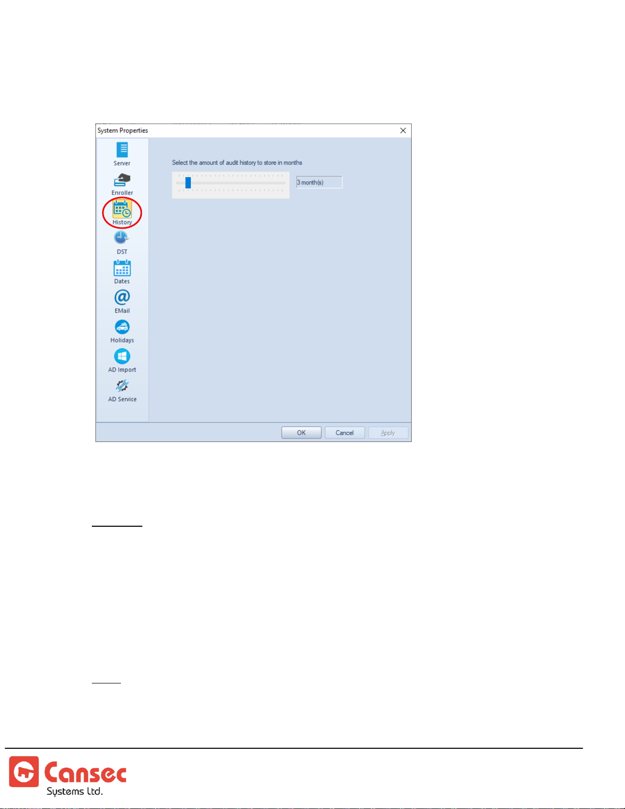
6. Use the slider to select the duration, in months, the audit history is to be retained.
Audit history older than the specified number of months will be purged
automatically.
7. DST (Daylight Saving Time). Optionally, select the date and time when daylight
saving time starts and ends. Specify the minutes of adjustment.
Example: See image below
DST starts on March 11, 2018 at 2AM and the clock on the control panel will
be turned forward 60 minutes.
DST ends on November 4, 2018 at 2AM and the clock on the control panel
will be turned backward 60 minutes.
All onboard schedules e.g. access schedules, unlock schedules etc… will be
changed accordingly by DST adjustment.
Note: In addition to the DST settings, the First Access Server software uses the clock from the
computer to automatically synchronize the clocks of all the controllers. The
synchronization occurs daily at 3:00 AM to ensure that the clocks of all controllers are
updated accordingly even if DST is not configured on each panel.
First Access Page 12 of 88
Operator Guide October 2020 • Rev. 2.3
Page 13
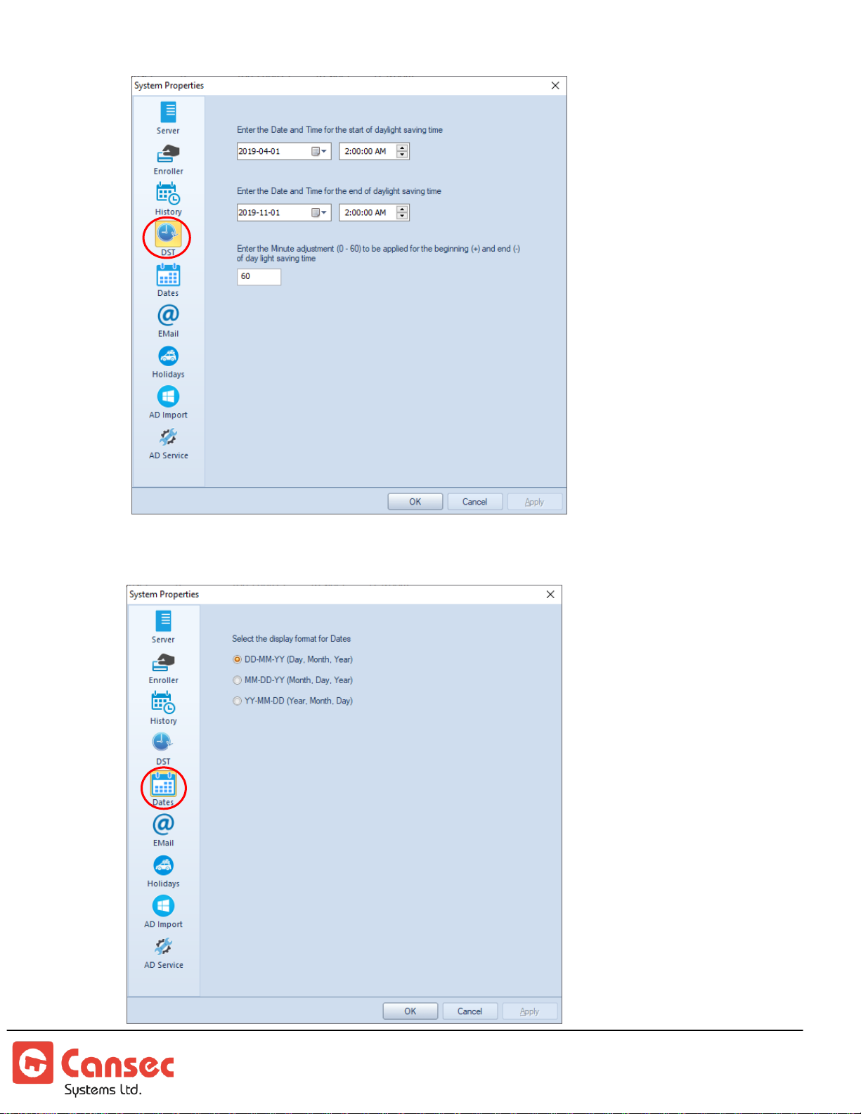
8. Dates format. Select a desired format and click OK to finish.
First Access Page 13 of 88
Operator Guide October 2020 • Rev. 2.3
Page 14
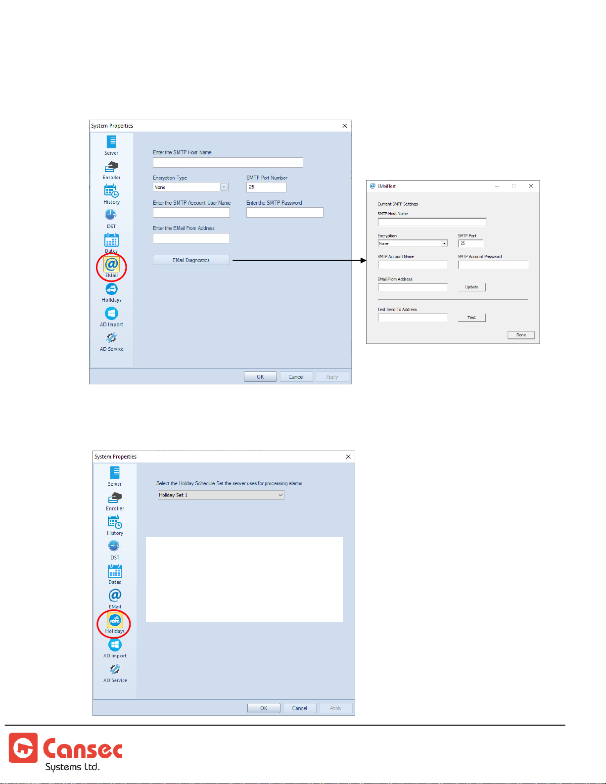
9. Email notification feature is available in First Access Advanced only. For email
There are 100 holiday sets available.
See Holiday Schedules section for
instructions on how to setup holiday
before selecting it. Holiday Set 1 is the
default selected holiday.
setup, contact IT personnel or email administrator for required information to enter
in the email setup screen.
10. Alarm holiday schedules are available in First Access Advanced only. They are used
to determine when to process alarms.
First Access Page 14 of 88
Operator Guide October 2020 • Rev. 2.3
Page 15
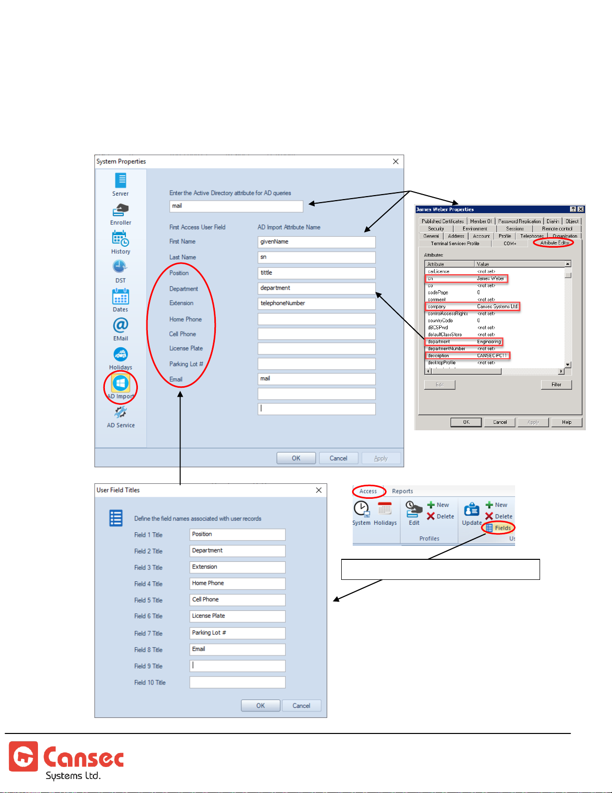
11. Active Directory (AD) Import is available in First Access Advanced Only. When
User Fields can be defined from here
All attributes must first be
setup up by IT personnel.
Sample user attributes
adding a cardholder in First Access software, this optional feature will help to
import the name and other attributes of that user from Active Directory into First
Access. All attributes must first be setup by the IT personnel. Active Directory
Attributes below could be obtained from IT personnel.
First Access Page 15 of 88
Operator Guide October 2020 • Rev. 2.3
Page 16
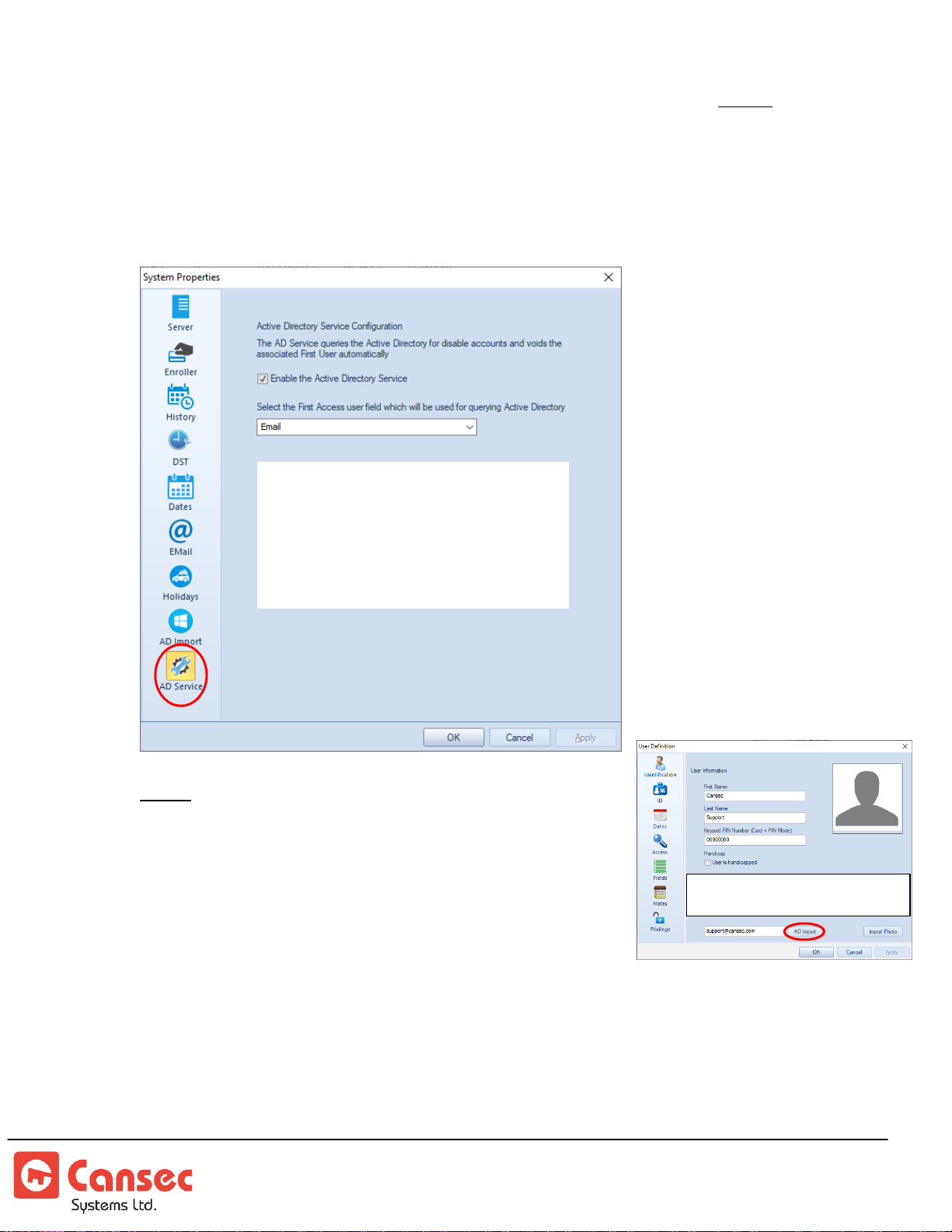
12. Active Directory Service is required to be enabled and configured only if Active
The Active Directory (AD) server
should be on the same LAN or
network with the First Access server.
The First Access server uses serverless
binding and RootDSE so there is no
need to specify where the AD server is.
Active Directory (AD) Import is
available in First Access Advanced Only.
Directory Import is used. This service is part of the First Access Advanced software
which communicates with the Active Directory to query and retrieve attributes of
users. It will also monitor the status (disabled status only) of users from Active
Directory and should one be disabled then that user record from First Access
database will also be disabled and set to inactive.
Notes:
First Access
software queries the AD server once every
hour for disabled accounts or users and automatically
disables those users from the
from the control panels accordingly. If those users are reenabled from the AD they are not automatically enabled
from the
First Access
Only one way communication from the
modify anything in the AD server but only monitors for disabled accounts.
First Access
does not automatically update the user fields associated with those attributes
if there are changes to those attributes. Use the AD Import button in the user definition
First Access Page 16 of 88
Operator Guide October 2020 • Rev. 2.3
page to manually import the changes of the attributes.
First Access
database and
database or from the control panels.
First Access
software to the AD server. It does not
Page 17
Step 3. Panel and Reader Definition
Note: Auxiliary Input
and Output are
available in
First
Access Advanced
only.
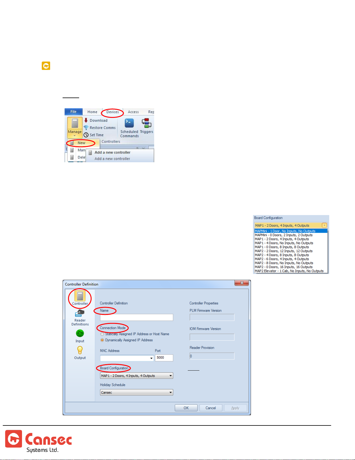
ADD PANEL
1. Select Devices->Manage->New.
Note: Scheduled Commands and Triggers are available in
First Access Advanced
only.
2. Enter a name for the panel, e.g. First Panel. By default, all MAPX panels are set
to obtain an IP address automatically. Select Dynamically Assigned IP Address
and select a MAC address associated with the panel. If you set a static IP address
for the panel (see Installation Guide for IP Address and Port configuration) then select
Statically Assigned IP Address or Host Name, and enter
the IP Address or the host name and the port number of
the panel. Select board configuration. The factory default
configuration is 2 Doors. Optionally it can be upgraded
via purchasing a provisioning file. Controller properties
will be shown when communication is established.
First Access Page 17 of 88
Operator Guide October 2020 • Rev. 2.3
Page 18
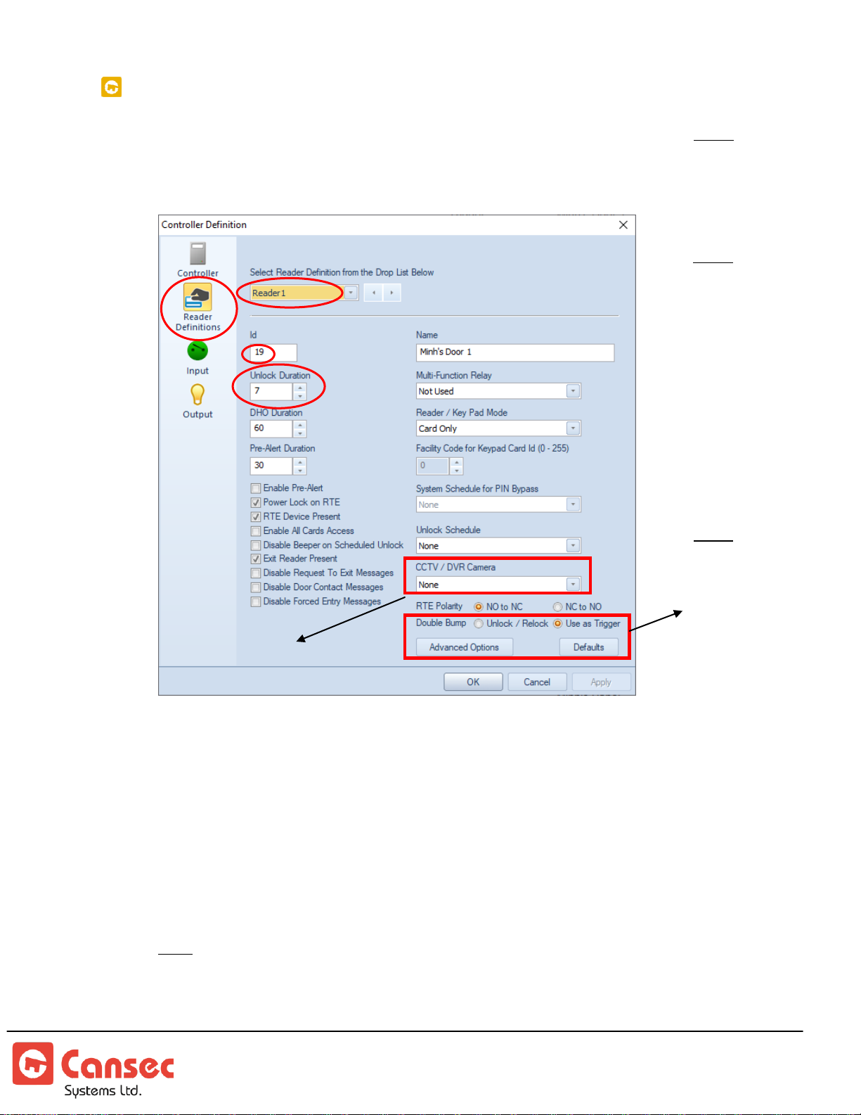
ADD READER
Note:
Auxiliary
Input and
Output are
available in
First Access
Advanced
only.
Note:
Available in
First Access
Advanced
only.
Add-on option
for First Access
Advanced only.
1. Select
Reader with Id 0 is an undefined reader. Each reader has its own unique Id. Use the
drop-down arrow or the left and right arrows to get to the desired reader.
Reader Definitions
. Reader Id is auto-generated by selecting it. Note:
First Access Page 18 of 88
Operator Guide October 2020 • Rev. 2.3
2. Select an unlock duration, in seconds (60 seconds max.), for the door when a
valid credential is presented or when an exit button is pressed.
3. Select a DHO (Door Held Open) time (300 seconds max.) for the panel to wait
before activating the multi-function relay when the door is left open for too long.
This requires the door to have a door contact installed and the multi-function
relay configured as Door Held Open relay.
4. Select a pre-alert time for the reader to emit a warning tone when the door is left
open for too long before it initiates a constant reader beep. The pre-alert time is
greater than the unlock time but less than the DHO time.
Note: In the example image above, the Pre-Alert Duration is set to 30 seconds.
5. Enter a name for the reader, e.g. Front Door or IT Room.
6. Select the desired function to assign to the multi-function relay. This relay can be
assigned to only one of the following functions:
Page 19
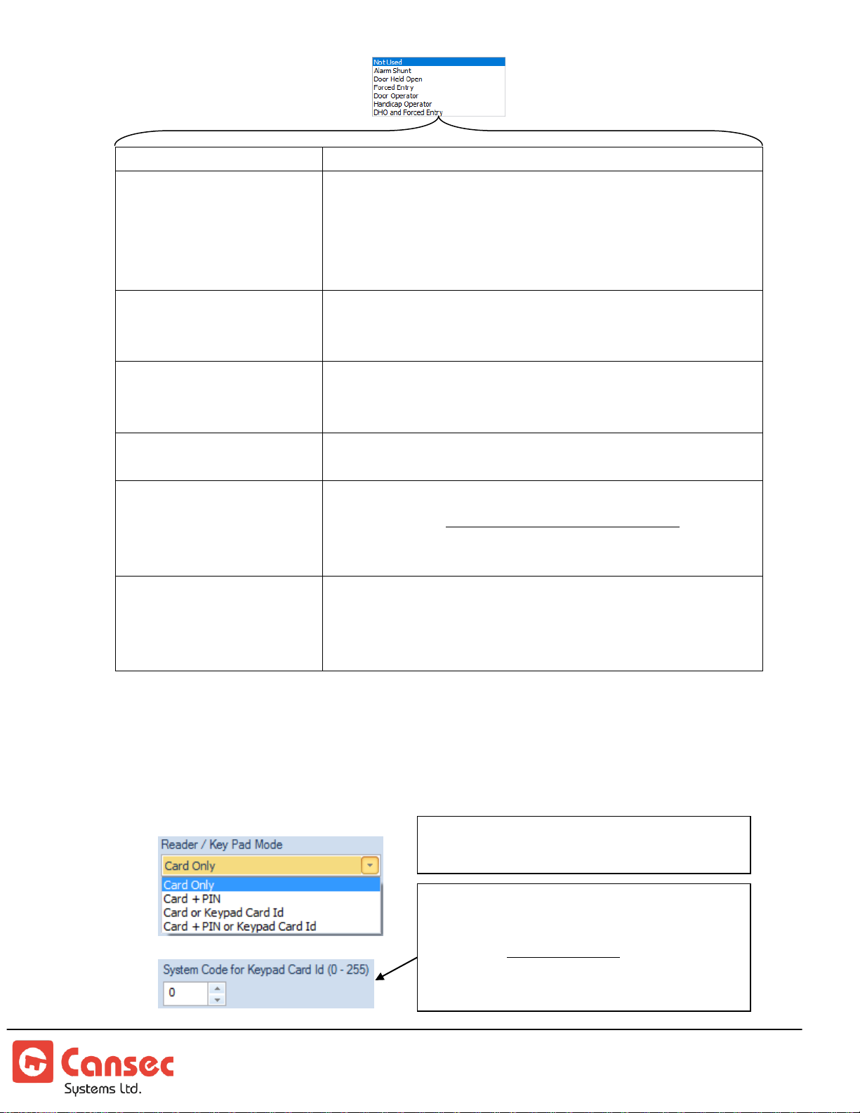
Not Used
This relay is not used at all.
Alarm Shunt
This relay is used to shunt an alarm when an access granted
or an exit button event occurs. When used, this relay is
activated prior to the lock relay’s activation and deactivated
after the door contact is closed. If door contact is not used
then it’s deactivated when the lock is relocked.
Door Held Open
This relay is used to activate another device (e.g. an external
light strobe or alarm) when the door is held open longer than
the pre-set time.
Forced Entry
This relay is used to activate another device (e.g. an external
light strobe or alarm) when the door is forced open without a
valid credential or an exit button press.
Door Operator
This relay is used to activate a door operator after an accessgranted or an exit button event occurs.
Handicap Operator
This relay is used to activate a door operator only when a
valid credential, designated as handicap credential, is
presented at a reader. Exit button event also activates this
relay.
DHO and Forced Entry
This relay is used to activate another device (e.g. an external
light strobe or alarm) when the door is held open longer than
the pre-set time or when the door is forced open without a
valid credential or an exit button press.
System/Facility Code (between 0 and
255 inclusive) must be entered
whenever Keypad Card Id is involved.
Not required for Card Only mode or
Card + PIN mode.
4-bit-burst keypad required. Preferably
Cansec tested keypads.
7. Select an optional unlock schedule. There are 255 available unlock schedules.
The unlock schedule, when defined and used, allows the door to automatically
unlock and relock at pre-defined times. If not used, select None.
8. If using keypad select one of the available modes below.
First Access Page 19 of 88
Operator Guide October 2020 • Rev. 2.3
Page 20
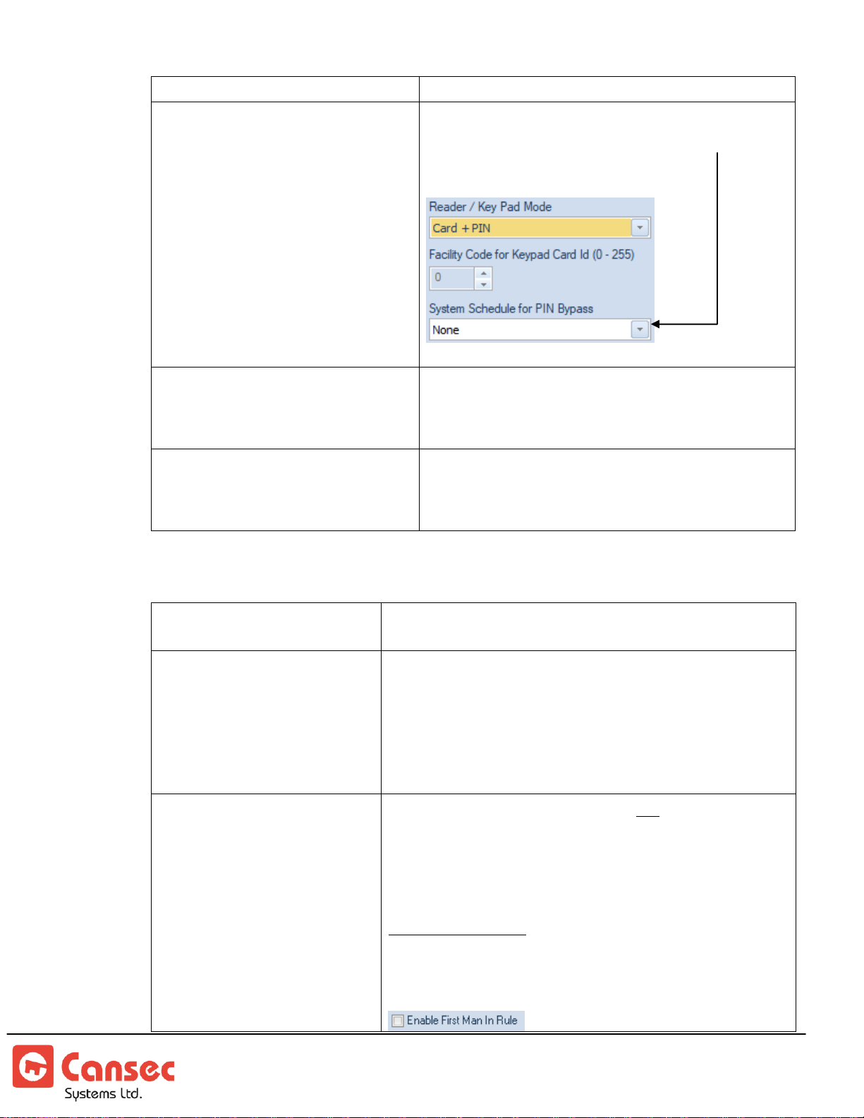
Card Only
Only cards are used, no keypad or PIN.
Card + PIN
Card presentation followed by PIN entered from
keypad. Optionally, select a system schedule you
have defined to bypass PIN requirement.
Card or Keypad Card Id
(For P-620 or P-640 keypad, use provided 4-
bit bust programming key to program the
keypad. See keypad manual for more info)
Card presentation or use keypad to enter card
number e.g. (asterisk) * card number #
(pound)
Card + PIN or Keypad Card Id
(For P-620 or P-640 keypad, use provided 4-
bit bust programming key to program the
keypad. See keypad manual for more info)
Card presentation followed by PIN entered from
keypad or use keypad to enter card number e.g.
(asterisk) * card number # (pound)
Enable Pre-Alert
Enable reader warning tone when the door is held open
longer than preset time.
Power Lock on RTE
Activate the lock and shunt the door contact when RTE
(Request To Exit) button is pressed. If unselected, only
the door contact is shunted. This option allows the
installer to install an indoor motion sensor hooked up to
RTE to trigger a valid egress without generating a forced
entry when the door is opened from inside.
Enable First-Man-In Rule
If this rule is enabled, the door will not automatically
unlock (based on its selected unlock schedule) until the
first valid credential is presented at the reader. If no
unlock schedule is used then this option has no effect.
First Access Express:
When selected, the rule applies to all valid credentials
9. Select optional features below.
First Access Page 20 of 88
Operator Guide October 2020 • Rev. 2.3
Page 21
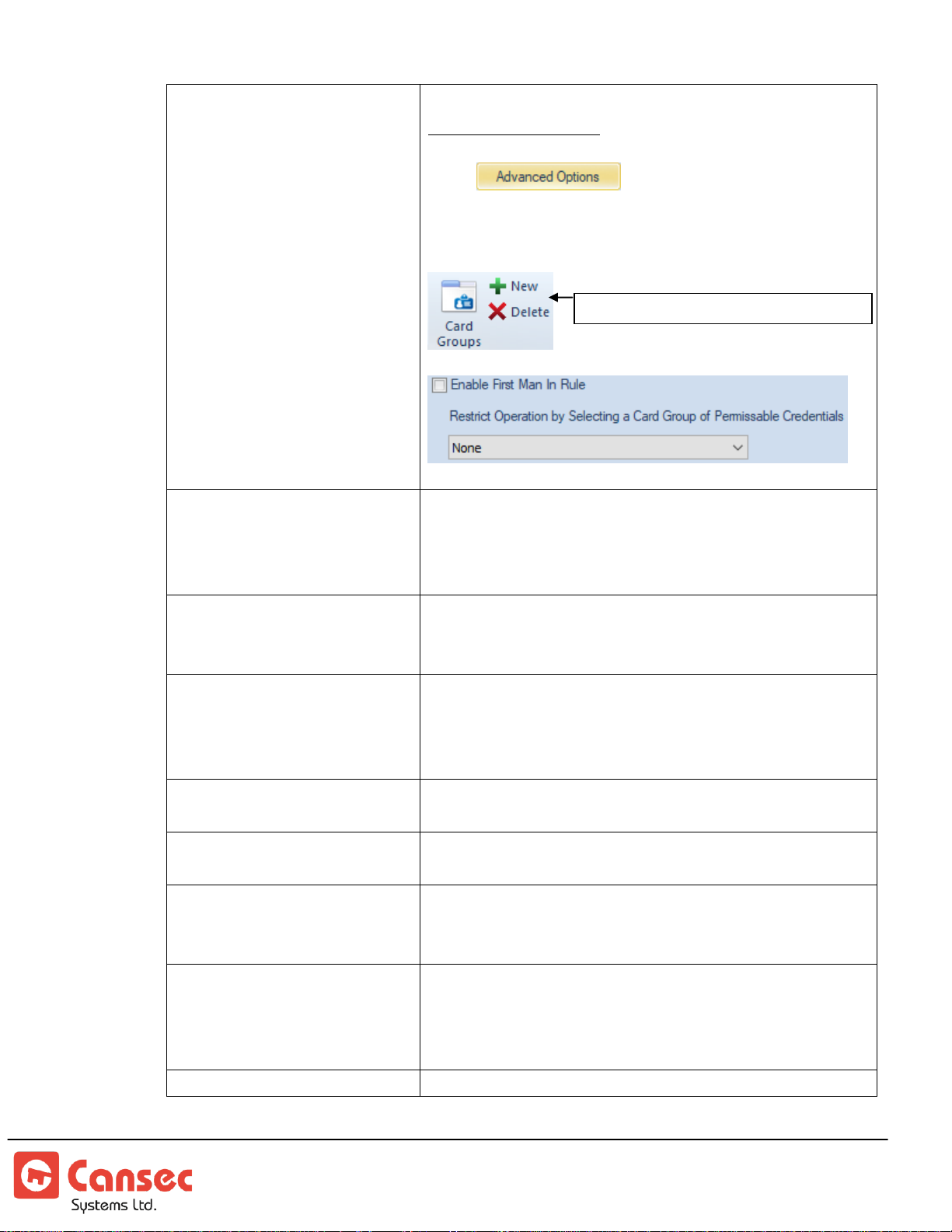
First Access Advanced:
Select to show “Enable First Man In
Rule” option. When selected, you have options to select a
predefined group of credentials the rule should apply to or
to select none for the rule to apply to all valid credentials.
Enable All Cards Access
Granting access to all cards (up to 64-bit) with or
without being registered in the system. This option should
be used with discretion and must be disabled when all
cards have been registered in the system.
Disable Beeper on
Scheduled Unlock
The beeper of the reader normally beeps when the door is
unlocked on a schedule. However, the beeper can be
disabled by selecting this option.
Exit Reader Present
Indicates that there is an exit reader mounted on the
egress side of the door. This reader is wired up to the
same port of the entry reader mounted on the ingress side
of the door. See installation guide.
Disable Request To Exit
Messages
Disable request to exit messages from being displayed and
recorded in the software.
Disable Door Contact
Messages
Disable door contact messages from being displayed and
recorded in the software.
Disable Forced Entry
Messages
Disable forced entry messages from being displayed and
recorded in the software. Also disable the event from the
controller
RTE Device Present
Check off if Request-To-Exit device is installed. If no
RET device is installed then the controller will not
monitor forced entry event but door open/close and doorheld-open events only.
Default Button
Reset all options above to default.
Use this option to create Card Group(s)
First Access Page 21 of 88
Operator Guide October 2020 • Rev. 2.3
Page 22
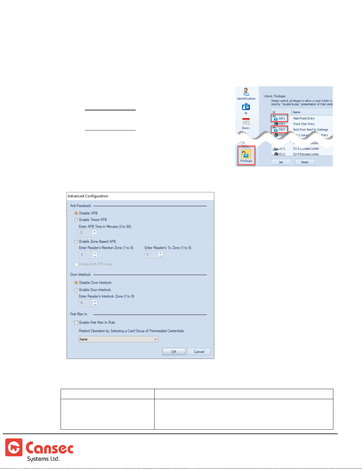
10. RTE (Request To Exit) Polarity can be set to either Normally Open (NO to NC)
Disable APB
APB is not enforced on this reader.
Enable Timed APB
Once a credential is used at this reader, it can be re-used
at this reader only after the APB time, in minutes (2 to
60), has elapsed.
or Normally Close (NC to NO) depending on the configuration of the RTE
button.
11. Double Bump (Double Card Swipe) can be used to unlock/relock a door or it
can be used as a trigger.
Unlock/Relock: Performs just one function
which is toggling the lock.
Used as Trigger: Performs one of the
functions other than just unlock/relock. See
Trigger section for more information.
12. Advanced options are available in First Access
Advanced only.
13. Select one of the options below for each individual reader.
First Access Page 22 of 88
Operator Guide October 2020 • Rev. 2.3
Page 23
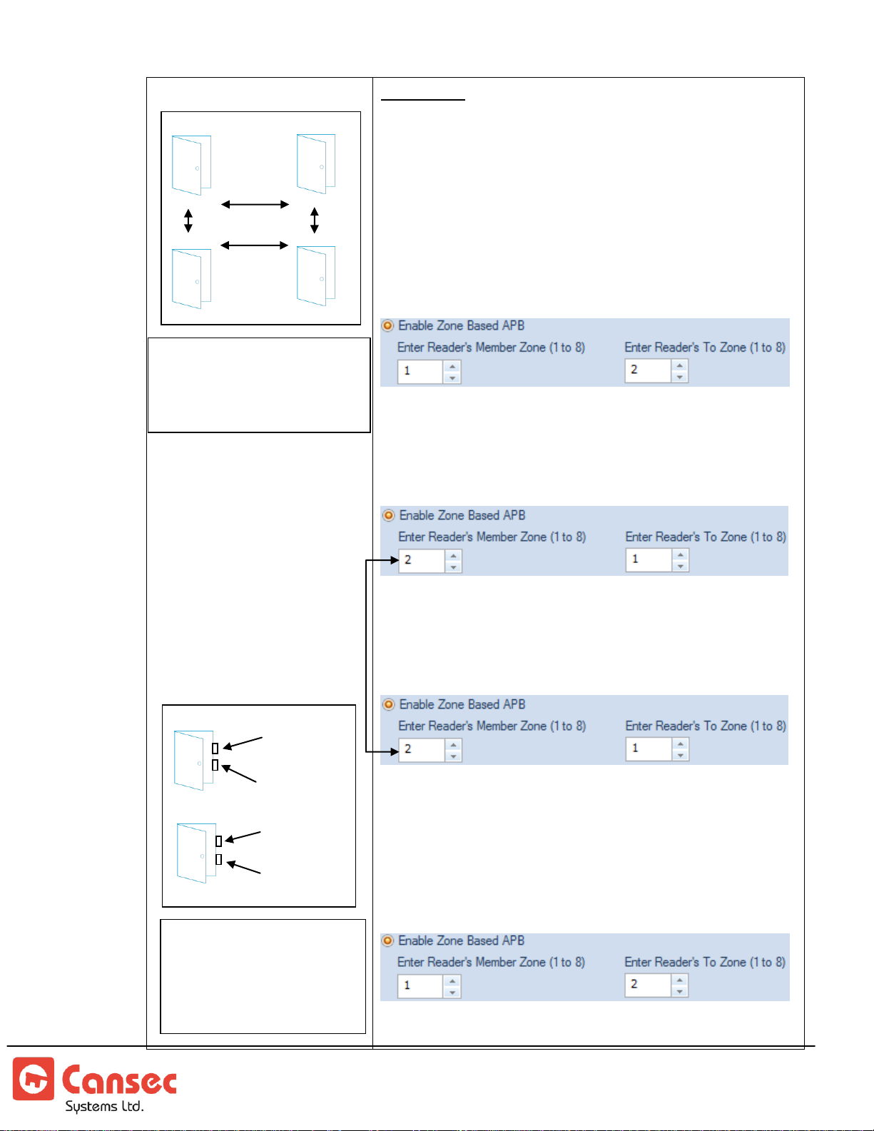
Enable Zone Based APB
If a door has an entry reader and
an exit reader, the exit reader will
be automatically assigned a zone
ID one higher than the entry
reader e.g. if the entry reader is
assigned zone 1 then exit reader
will be assigned zone 2 etc…
Example below shows that
credential entered at either entry
reader of front or back door will be
able to exit at any exit reader of
front or back door.
Important
: Only readers on the same controller can be
grouped into Zones where each member reader has the
same zone ID. Grouping readers from different controllers
is not supported.
When zone based APB is enabled on a reader, any valid
credential, when presented at that reader will be recorded
as being in the “to zone”. See example below.
Reader 1: Zone 1 to 2
Valid credentials presented at reader 1 will be assigned to
zone 2, and those credentials can only be used at any
member reader of zone 2 or reader that has APB disabled.
Reader 2: Zone 2 to 1
Valid credentials presented at reader 2 will be assigned to
zone 1 and those credentials can only be used at any
member reader of zone 1 or reader that has APB disabled.
Reader 3: Zone 2 to 1
Reader 2 and reader 3 have the same member zone ID.
Valid credentials presented at reader 2 or reader 3 will be
assigned to zone 1, and those credentials can only be used
at any member reader of zone 1 or reader that has APB
disabled.
Reader 4: Zone 1 to 2
Reader 1 and reader 4 have the same member zone ID.
Valid credentials presented at reader 1 or reader 4 will be
Reader 2
Reader 1
Zone 2
Zone 1
Reader 4
Reader 3
The same
controller for
all readers
Zone 1
Zone 2
Same controller
Front Door
Exit Reader
Zone 2
Entry Reader
Zone 1
Exit Reader
Zone 2
Entry Reader
Zone 1
Back Door
In this example, credential
accessed any zone 1 reader may
access any zone 2 reader.
Similarly, credential accessed at
any zone 2 reader may access
any zone 1 reader.
In this example, credential accessed
any zone 1 reader may access any
zone 2 reader. Similarly, credential
accessed at any zone 2 reader may
access any zone 1 reader.
First Access Page 23 of 88
Operator Guide October 2020 • Rev. 2.3
Page 24
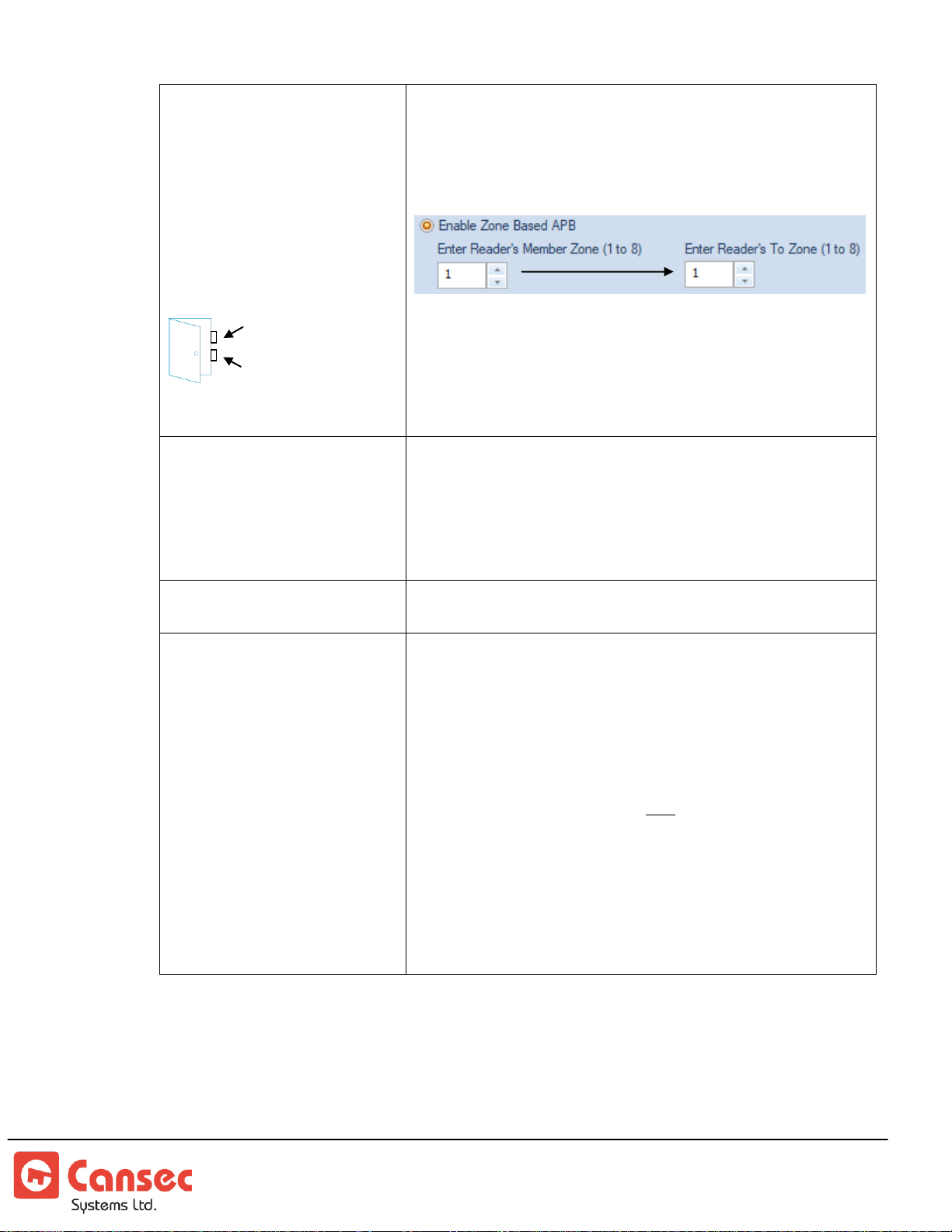
If there is only one door
having entry and exit
readers participating in
zone anti-passback then
the member and the enter
zone must all be set to the
same ID. ID cannot be reused for other zones.
assigned to zone 2, and those credentials can only be used
at any member reader of zone 2 or reader that has APB
disabled
Reader 1: Zone 1 to 1 (or 2 to 2 or 3 to 3 etc…)
Just one reader X (X=1, 2, 3 or 4) has entry and exit
readers participating in Zone anti--passback. Valid
credentials presented at the entry reader will be assigned to
exit reader’s zone, and those credentials can only be used
only at that exit reader or reader that has APB disabled.
Enable Soft APB Mode
Applicable to Zone Based APB only. When soft APB
mode is enabled, the controller will grant access to that
reader for any valid credential, even if it fails zone
verification. However, an event will be recorded indicating
that the credential has failed anti-passback verification.
Disable Door Interlock
Door interlock is not enforced on this reader.
Enable Door Interlock
Enforce door interlock on this reader. When enabled,
readers that have the same value (1 to 8) assigned will
participate in door interlock. Example, if reader A and
reader B have value 1 assigned to them then when reader
A’s door is open, or when reader A’s lock is energized then
reader B will not grant access to any credential until
reader A’s lock is de-energized and reader A’s door is
closed. The same logic applies to reader B. Optionally
more than 2 readers can participate in the same or
different door interlock zones e.g. readers A, B, C have
value 1 assigned or A, B have value 1 assigned and C, D
have value 2 assigned etc..
Entry Reader Zone 1
Exit Reader Zone 1
14. When advanced options have been selected and configured then Click OK to
save settings or click Cancel to ignore all settings.
15. To reset Timed or Zone Based APB, double click the desired reader displayed in
the device panel.
First Access Page 24 of 88
Operator Guide October 2020 • Rev. 2.3
Page 25
Note: Auxiliary Input and Output are
available in First Access Advanced only.
Note: Add-on option
for First Access
Advanced only.
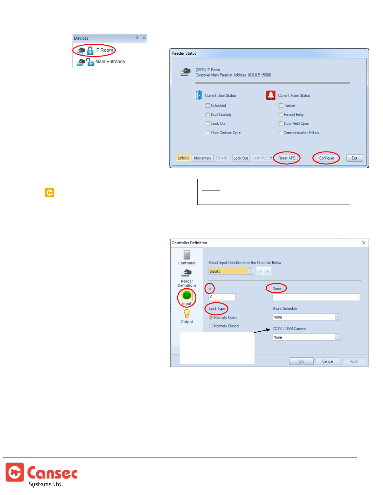
16. Click Reset APB to clear
anti-passback, timed or
zone based, for the selected
reader.
17. To reconfigure the reader,
click Configure.
DEFINE AUXILIARY INPUT POINT
If the panel is provisioned with 2 doors then there are 4 auxiliary inputs available
for use. If the panel is provisioned with 4 doors then there are no auxiliary inputs
available for use.
1. Select Input icon from the
left panel.
2. From the right panel,
select an available input
point from the drop list.
3. Use system-assigned ID or
manually enter an unassigned ID e.g. 1, 2 or 3
etc… for this input point.
Each input point has a
unique ID.
4. Enter an appropriate name
for the input point e.g. Panic Button.
5. Select a type for the input point e.g. Normally Open or Normally Closed.
6. Optionally, select a defined shunt schedule to shunt the input event from being
processed. A shunt schedule must be manually defined. A shunt schedule can be
used to ignore or to process input events at different times. Otherwise select
None for events to be processed at all times.
First Access Page 25 of 88
Operator Guide October 2020 • Rev. 2.3
Page 26
DEFINE AUXILIARY OUTPUT POINT
Note:
Auxiliary
Input and
Output are
available in
First Access
Advanced
only.
Note: Add-on option
for First Access
Advanced only.
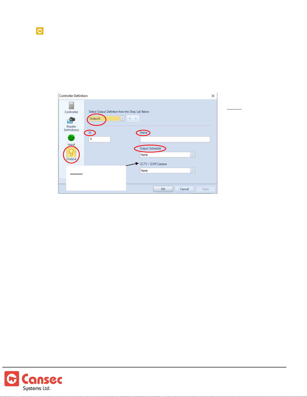
Similar to input point configuration, if the panel is provisioned with 2 doors then
there are 4 auxiliary outputs available for use. If the panel is provisioned with 4
doors then there are no auxiliary outputs available for use.
1. Select Output icon from the left panel.
2. From the right panel, select an available output point from the drop list.
3. Use system-assigned ID or manually enter an un-assigned ID e.g. 1, 2 or 3 etc…
for this output point. Each output point has a unique ID.
4. Enter an appropriate name for the output point e.g. Alarm Horn.
5. Optionally select a defined output schedule to automatically activate the output
point. Output schedules must be defined by the operator before they can be
selected. An output can be used to activate or deactivate a device based on a
schedule. Otherwise, select None if no schedule is assigned.
First Access Page 26 of 88
Operator Guide October 2020 • Rev. 2.3
Page 27
EDIT AND DELETE PANEL
Available in
First Access
Advanced
only.
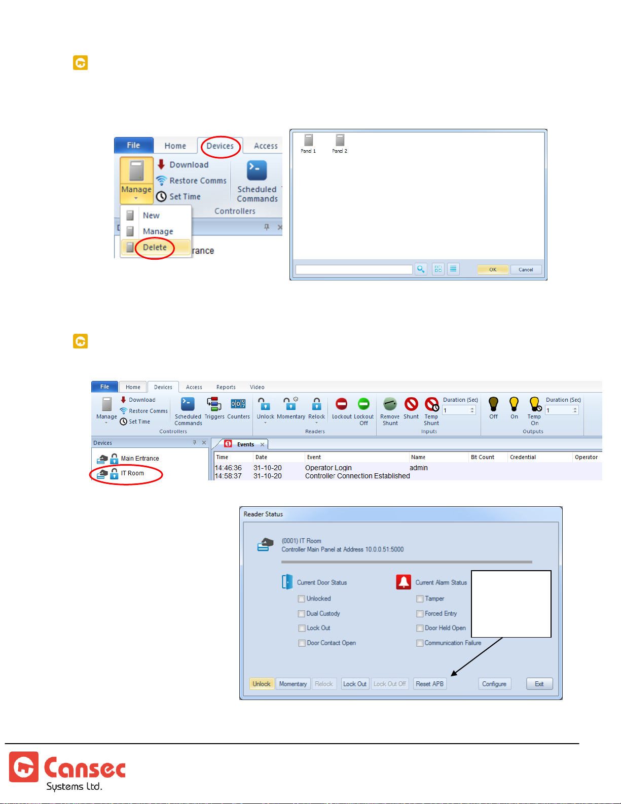
1. To edit a panel select Devices->Manage, or select Devices->Delete to delete a
panel.
2. Select a panel and click OK.
READER STATUS
Click on a reader to
view its status. Status
notifications will be
indicated by a check
mark in the
appropriate box.
First Access Page 27 of 88
Operator Guide October 2020 • Rev. 2.3
Page 28
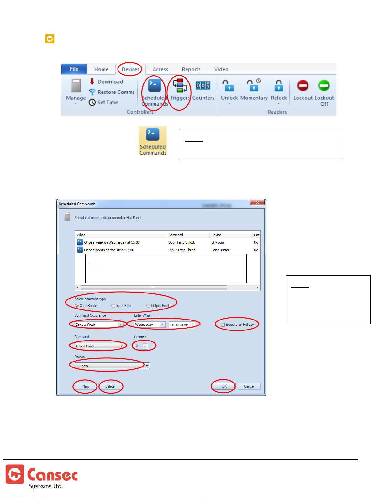
READER COMMANDS, SCHEDULED COMMANDS, TRIGGERS, COUNTERS
Note: Schedule Commands are available in
First Access Advanced only.
Note: Schedule Commands are available in
First Access Advanced only.
Note: Only 200
Schedule Commands
are available per
panel.
Scheduled Commands
Scheduled commands are used to command locks, input point and output point
based on a schedule that is different from the weekly schedule.
1. Click Scheduled Commands and click New
2. Select a desired reader
First Access Page 28 of 88
Operator Guide October 2020 • Rev. 2.3
Page 29
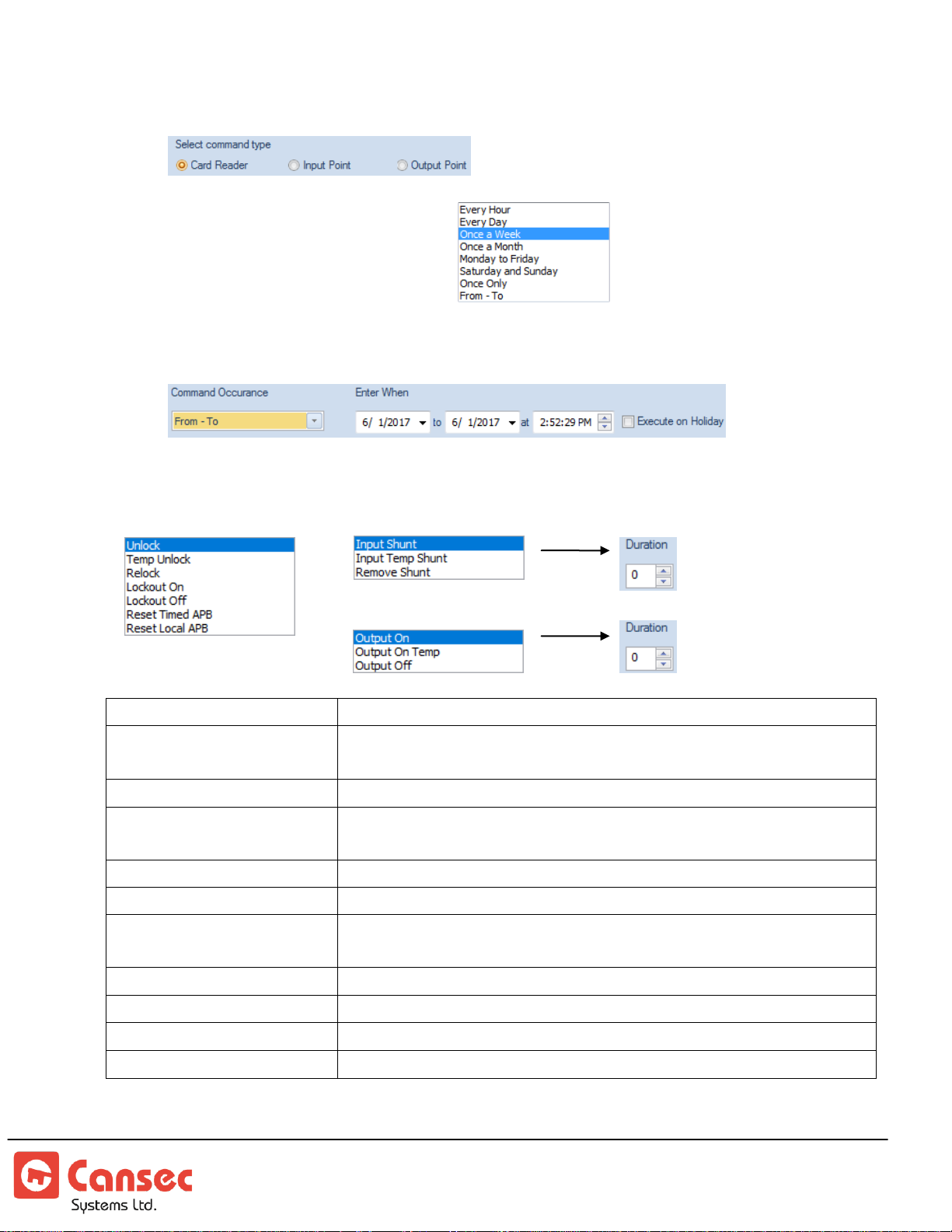
3. Select a command type
Unlock
Unlock the lock. The lock remains unlocked.
Temp Unlock
Temporary unlock the lock and relock after the unlock time has
expired.
Relock
Relock the lock.
Lockout On
Disable the card reader. Card reader flashes red and green. Only
credentials with lockout-bypass exemption will be granted access.
Lockout Off
Enable the card reader and remove it from the lockout state.
Input Shunt
Input events from the input point will not be processed at all.
Input Temp Shunt
Temporarily suspend processing of input events from this input
point until the duration has expired.
Remove Shunt
Disable shunt and resume processing input point events normally.
Output On
Activate the output point.
Output On Temp
Temporarily activate the output point for the configured duration.
Output Off
Deactivate the output point.
Duration (maximum
value is 1000 seconds)
is applicable only to
Input Temp Shunt and
Output On Temp
Commands for input
Commands for Reader
Commands for output
4. Select Command Occurrence.
5. Enter the day and time when the command will occur and select if it should be
executed on a holiday.
6. Select the command that should be applied to the device
7. Click OK to save settings.
First Access Page 29 of 88
Operator Guide October 2020 • Rev. 2.3
Page 30
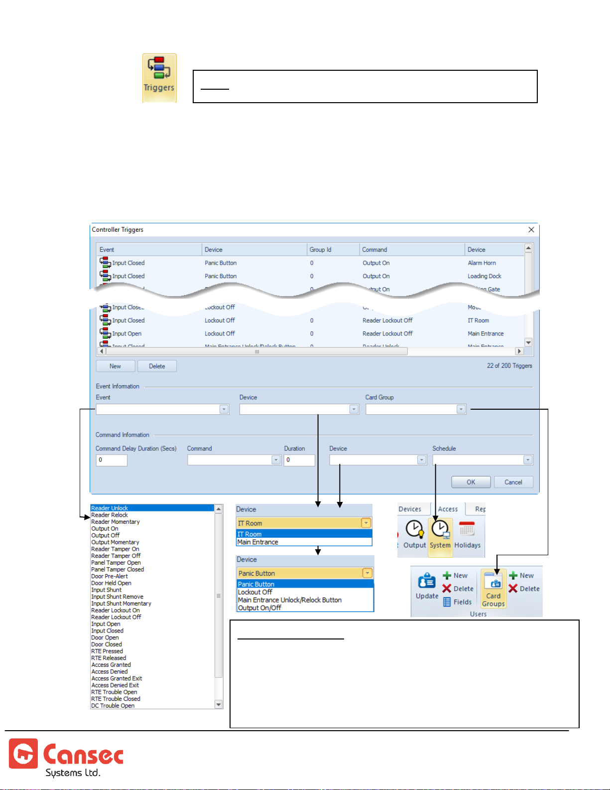
Triggers
Note: Triggers are available in First Access Advanced only.
Event Information:
When an event occurs from a certain device, a desired command
may be selected in the Command Information section to trigger
another action on a different device. For example, when access is
granted at the Main Entrance, open the Parking Gate and activate
the Loading Dock.
Programmable on-board triggers (maximum 200 triggers) are used to respond to
events that happen within a particular panel but not globally across multiple panels.
For example, a trigger can be programmed to turn a light on, among other things,
when access is granted at a particular door. It accomodates built-in delay timer, card
group, execution schedule. Triggers are quite powerful and flexible in many ways.
First Access Page 30 of 88
Operator Guide October 2020 • Rev. 2.3
Page 31
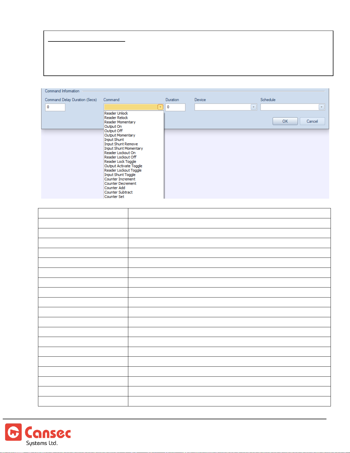
Reader Unlock
Unlock reader
Reader Relock
Relock reader
Reader Momentary
Unlock reader momentarily
Output On
Activate output
Output Off
Deactivate output
Output Momentary
Activate output momentarily
Input Shunt
Shunt or deactivate input
Input Shunt Remove
Remove input from being shunted
Input Shunt Momentary
Momentarily remove input from being shunted
Reader Lockout On
Lock out or lock down reader.
Reader Lockout Off
Remove reader from being locked out
Reader Lock Toggle
Toggle the lock from locked to unlocked or vice versa
Output Activate Toggle
Toggle the output from ON to OFF or vice versa
Reader Lockout Toggle
Toggle the reader lock out from ON to OFF or vice versa
Input Shunt Toggle
Toggle the input from shunted to un-shunted or vice versa
Counter Increment
Increment the counter by 1.
Counter Decrement
Decrement the counter by 1. It does not decrement pass 0
Counter Add
Add counter with a number predetermined by the user
Counter Subtract
Subtract counter with a number predetermined by the user
Counter Set
Set counter to a specific value predetermined by the user
Command Information:
Select a command to be performed on another device when an event from a certain device occurs.
The delay time can be optionally set before the command is executed. The system schedule must be
used to schedule the command or otherwise the command will not be executed.
First Access Page 31 of 88
Operator Guide October 2020 • Rev. 2.3
Page 32
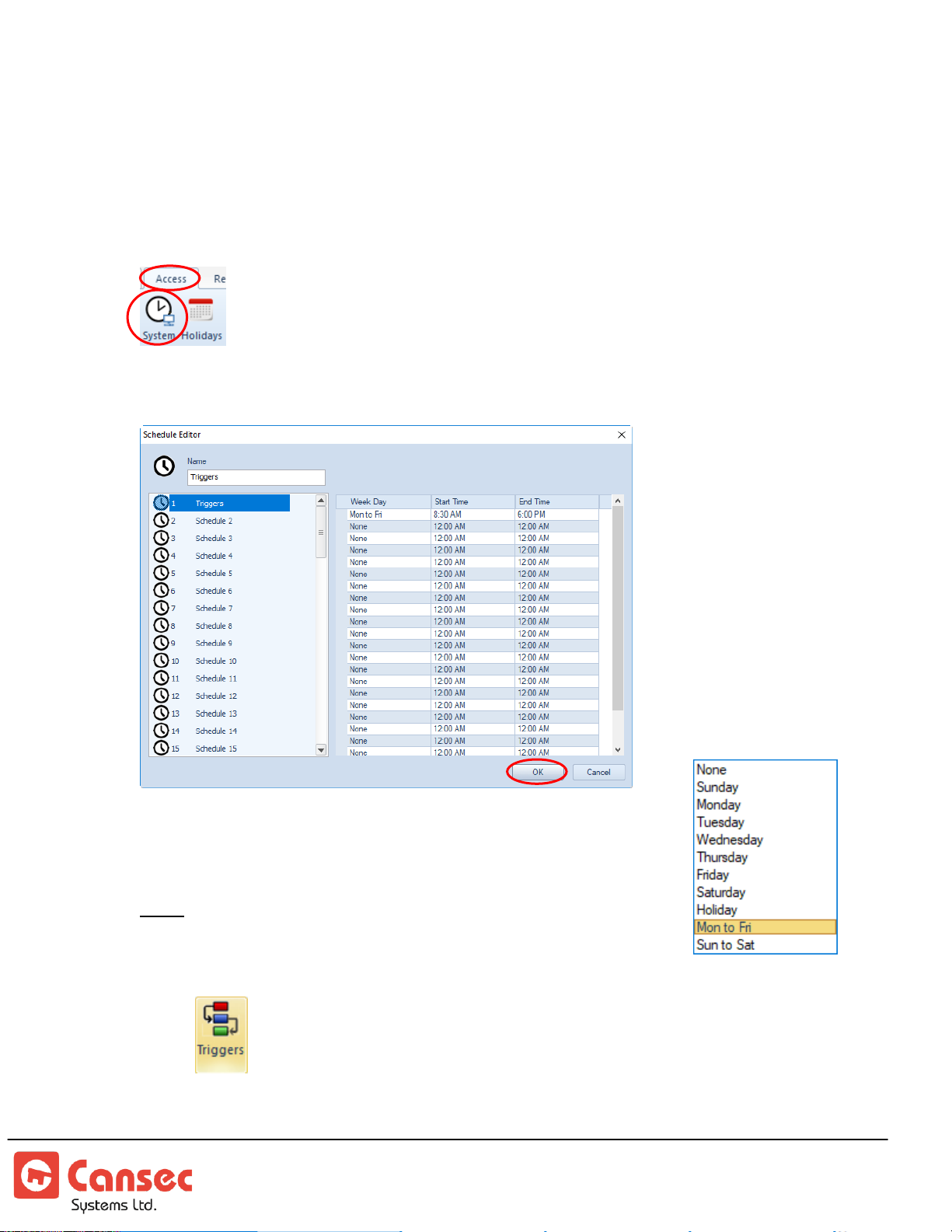
In the example below, there is only one panel named Main Panel. However, in some
situations there could be many panels. We will implement a trigger on this Main Panel
such that when the Main Entrance is momentarily unlocked, the panel will delay for 3
seconds then activates an output point connected to a Parking Gate for 10 seconds.
1. From the top menu select Access then select System
2. Select one of the available schedule and name it Triggers or some other name
3. Set the execution time from Monday to Friday between 8:30
AM and 6:00 PM
Note: Other options are available for Week Day as seen below
4. Select from the top menu
5. Select Main Panel from the list to have triggers implemented on.
First Access Page 32 of 88
Operator Guide October 2020 • Rev. 2.3
Page 33
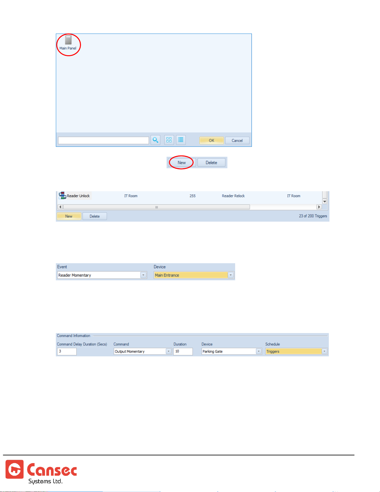
6. Click New to add a new trigger.
7. Select or highlight the newly added trigger normally found at the bottom of the list.
8. Select Reader Momentary from Event drop-down list and select Main Entrance from
the Device drop-down list.
9. Under Command Delay, enter 3. Under Command select Output Momentary. For
Duration enter 10. Under Device select Parking Gate and under Schedule select
Triggers which is the schedule we have previously defined.
10. Click New to add additional triggers or click OK to finish. New added triggers will
be downloaded to the panel automatically.
First Access Page 33 of 88
Operator Guide October 2020 • Rev. 2.3
Page 34
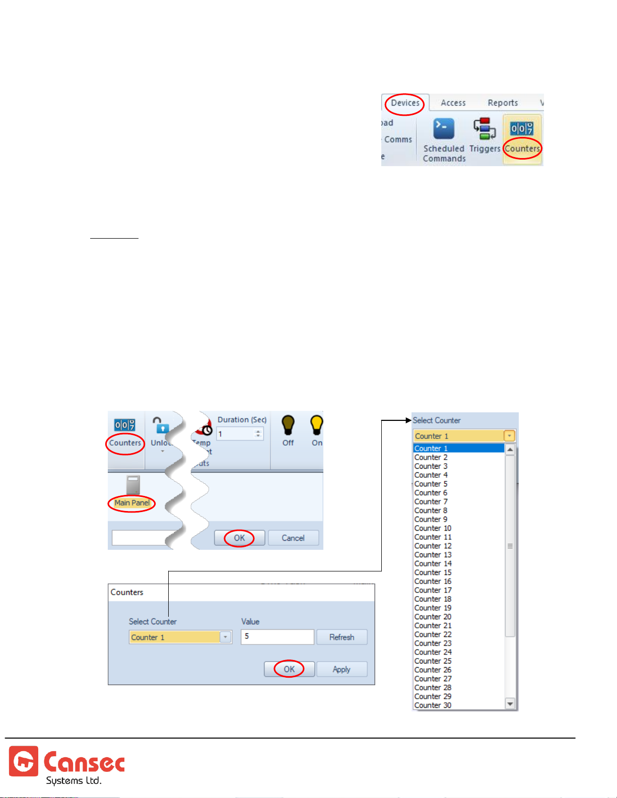
Counters
There are 40 counters available per controller.
Each counter can be used for different purposes.
For example, a counter can be used to count the
numbers of cars entering and exiting a parking lot,
and when a threshold is met it automatically
activates an output hooked up to digital signage to display the occupancy status of
the parking lot.
Example:
When car enters the entry gate increment the counter 1. If the counter reaches
the threshold activate an output point hooked up to digital signage to show the
lot is full and at the same time lockout the entry gate.
When a car exits the exit gate decrement the counter 1. If the counter reaches
below the threshold deactivate the output point to turn off the digital signage and
at the same time remove the lockout for the entry gate.
1. Set counter 1 of the Main Panel to a desired a threshold e.g. 5 or 100 etc…
First Access Page 34 of 88
Operator Guide October 2020 • Rev. 2.3
Page 35
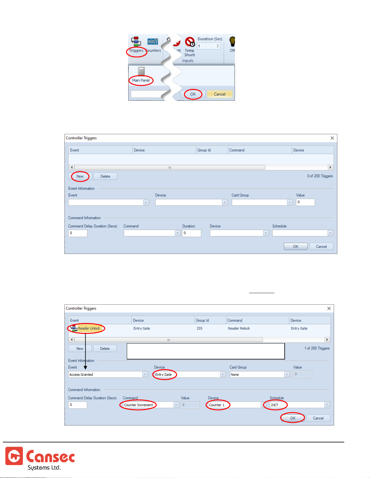
2. Create triggers
Increment “counter 1” when a car enters entry gate
3. Select New to create a new trigger
4. Select the new added trigger and change the event to Access Granted and change
the appropriate device, command, counter and schedule as seen below. If the
selected system schedule is not defined then the trigger will not be executed.
First Access Page 35 of 88
Operator Guide October 2020 • Rev. 2.3
Page 36
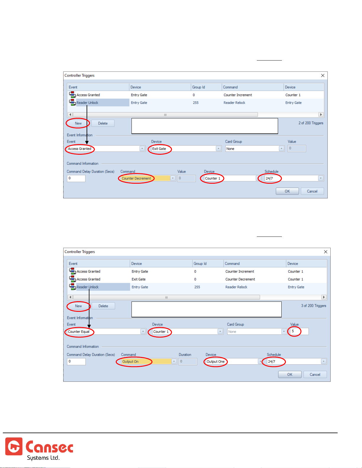
5. Select New again to create a new trigger. Change event to Access Granted and
Decrement “counter 1” when a car exits exit gate
Activate “Output One” when counter 1 reaches 5
change the appropriate device, command, counter and schedule as seen below. If
the selected system schedule is not defined then the trigger will not be executed.
6. Select New again to create a new trigger. Change event to Counter Equal and
change the appropriate device, command, counter and schedule as seen below. If
the selected system schedule is not defined then the trigger will not be executed.
In this example, if Output One is hooked up to a digital signage then it will be
activated when counter 1 reaches 5.
First Access Page 36 of 88
Operator Guide October 2020 • Rev. 2.3
Page 37
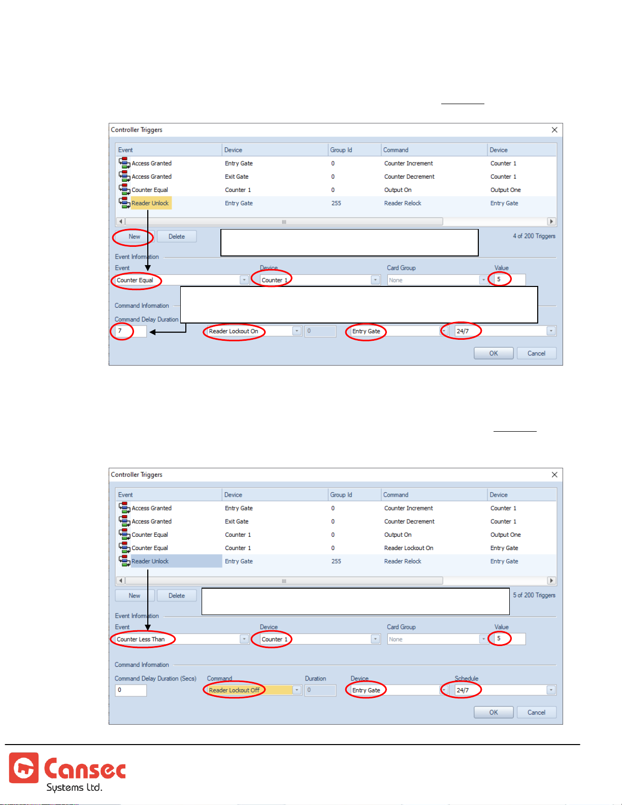
7. Select New again to create a new trigger. Change event to Counter Equal and
Lockout “Entry Gate” when counter 1 reaches 5
The delay must be set to equal to the unlock time of the gate to allow
the car enough time to enter the gate before locking it out
Remove Lockout “Entry Gate” when counter 1 is less than 5
change the appropriate device, command, counter and schedule as seen below. If
the selected system schedule is not defined then the trigger will not be executed.
8. Select New again to create a new trigger. Change event to Counter Less Than
and change the appropriate device, command, counter and schedule as seen
below. If the selected system schedule is not defined then the trigger will not be
executed.
First Access Page 37 of 88
Operator Guide October 2020 • Rev. 2.3
Page 38
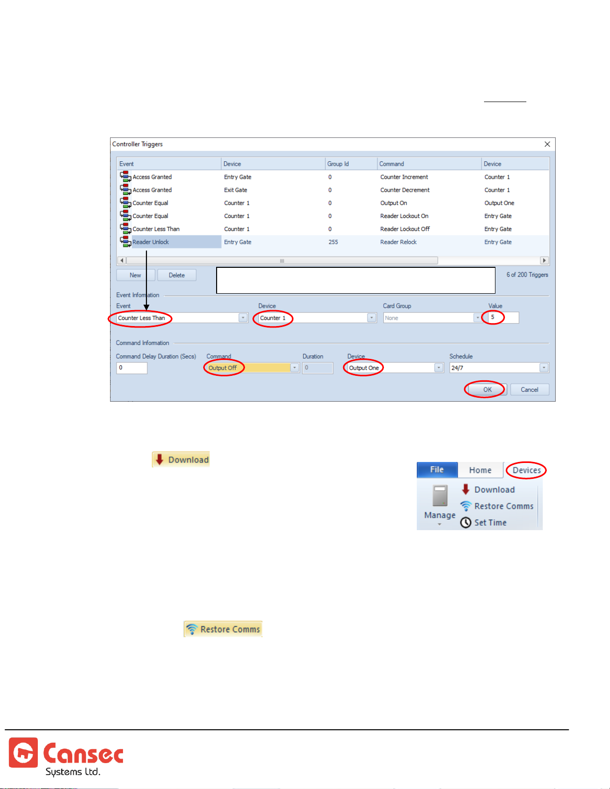
9. Select New again to create a new trigger. Change event to Counter Less Than
Deactivate “Output One” when counter 1 is less than 5
and change the appropriate device, command, counter and schedule as seen
below. If the selected system schedule is not defined then the trigger will not be
executed.
10. Click OK to finish.
Download
Changes are automatically downloaded and saved to
online panels. However, changes made while a panel is
offline must be manually downloaded to have them
applied.
1. Click Download
2. Select panel(s) and click OK
Restore Comms
Restore Comms Provide an immediate attempt to restore communication to offline
panels without waiting for an automatic communication-restore process to take
effect.
First Access Page 38 of 88
Operator Guide October 2020 • Rev. 2.3
Page 39
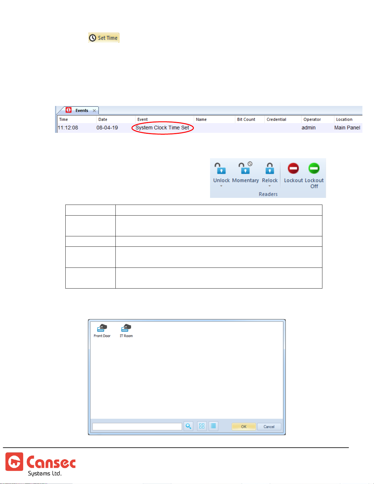
Set Time
Unlock
Unlock the lock and keep it unlocked
Momentary
Momentary unlock the lock for the duration set in the unlock time
setting of the door
Relock
Relock the lock
Lockout
Relock the lock and disable the card reader from granting access to
any credential. Card reader’s LED flashes red and green.
Lockout Off
Turn Lockout mode off. Card reader’s LED stays solid red and
lock remains locked.
Manually set the time on all controllers based on host computer’s clock. Set time
must be done whenever a new panel is added to the system for the panel to have the
current date and time. However, the First Access software automatically
synchronizes the time on all controllers on a daily basis.
Unlock, Momentary, Relock, Lockout and Lockout Off
1. Select an appropriate button, e.g.
Unlock, Relock, etc, to perform on the
readers.
2. Select a reader or readers and click OK.
First Access Page 39 of 88
Operator Guide October 2020 • Rev. 2.3
Page 40
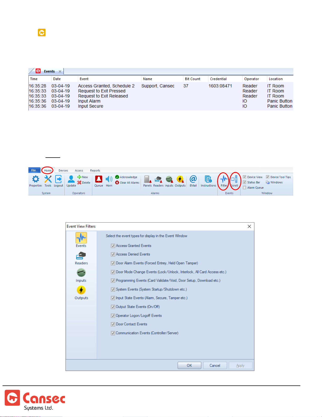
READER EVENTS
Note: Auxiliary Inputs and Outputs are available in First Access Advanced only.
All events are recorded in the database and displayed in the Events window.
Events can also be selectively filtered per reader, input/output point and vertical scroll bar
can also be enabled in the Event screen.
Event Filter: Select the event types for display in the Event Window
First Access Page 40 of 88
Operator Guide October 2020 • Rev. 2.3
Page 41
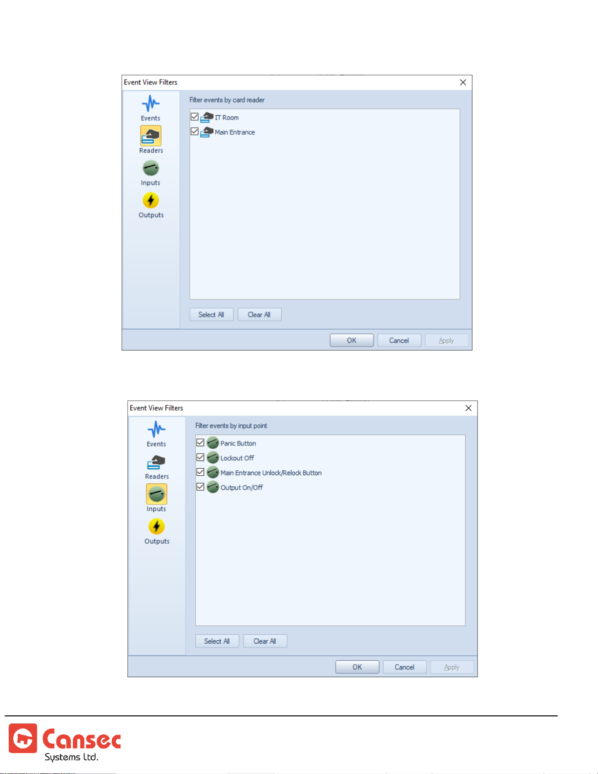
Reader Filter: Filter events by card reader
Input Filter: Filter events by input point
First Access Page 41 of 88
Operator Guide October 2020 • Rev. 2.3
Page 42
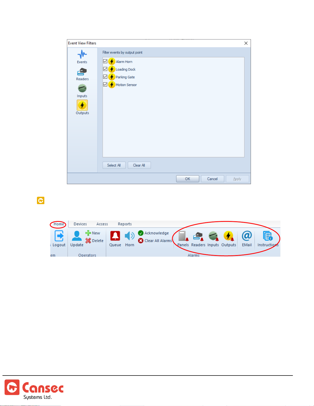
Output Filter: Filter events by output point
ALARM NOTIFICATIONS
Certain events or alarms from readers, inputs and outputs point can be selected to
show up in the alarm queue and optionally be notified via email when the event or
alarm occurs. Email notification is available only in First Access Advanced and uses
System Schedule for notification scheduling.
First Access Page 42 of 88
Operator Guide October 2020 • Rev. 2.3
Page 43
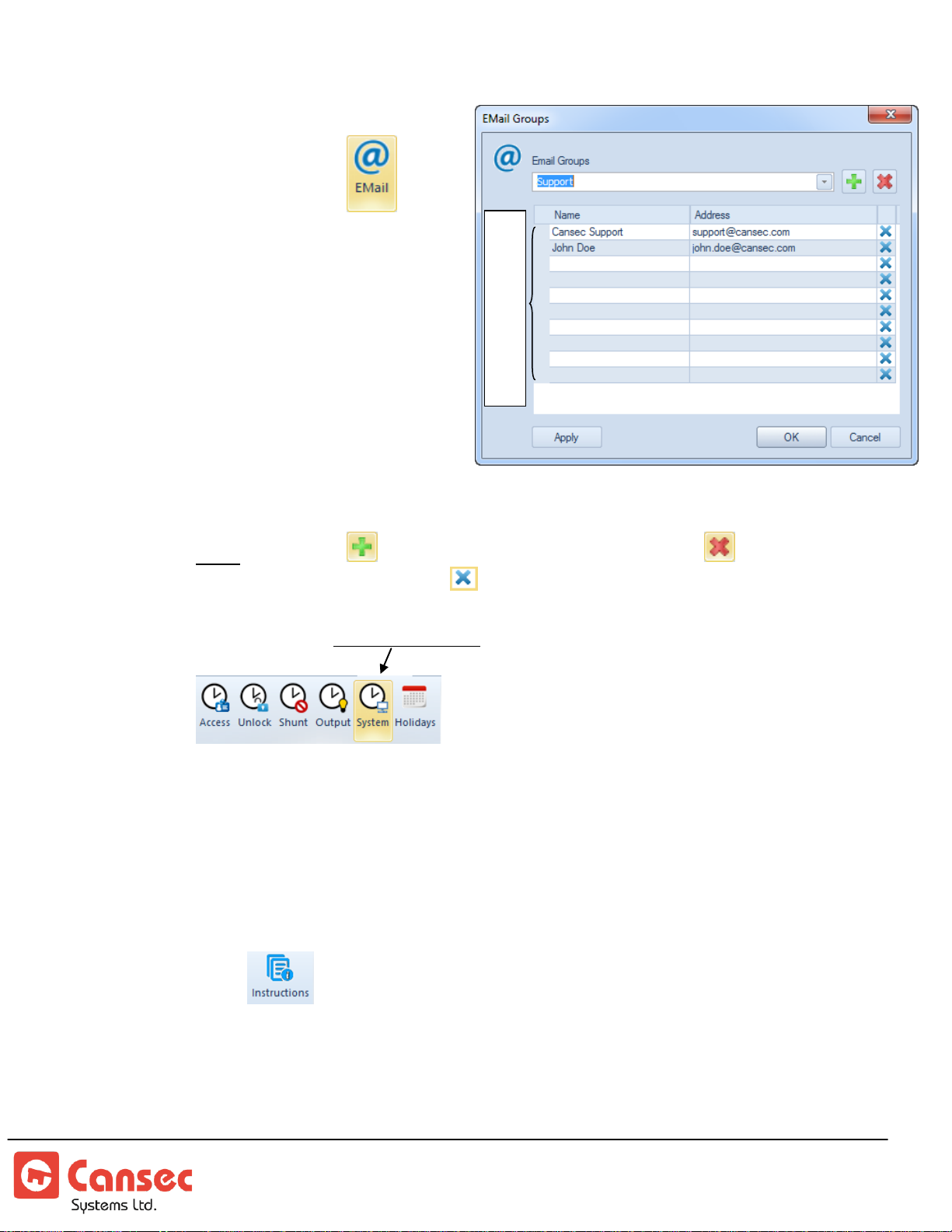
Email Groups
10 members per group
1. Click Email icon to
launch Email Groups
2. Enter the name for the group
e.g. Support or IT or Managers
etc…
3. Enter the name and
corresponding email address
for up to 10 members of each
group. Click Apply to save
changes to the current email
group.
4. Click OK when done.
Note: Use button to add addition email groups. Use button to remove an
email group. Use button to remove an email address.
Important: Use
System Schedule
for email notification scheduling.
Alarm Instructions
Instructions can be predefined to be included in the alarm queue or included
with the email alarm notification. Instruction may contain contact name or
phone number along with information to carry out in an event of an alarm.
1. Click icon to launch Alarm Instructions window containing a list of
instructions.
First Access Page 43 of 88
Operator Guide October 2020 • Rev. 2.3
Page 44
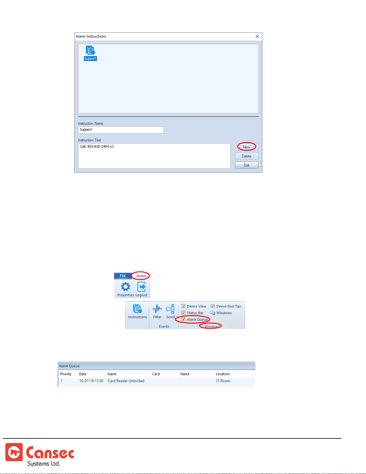
2. Click New to create new instruction.
3. Input a name for the instruction e.g. Support
4. Input the instructions in the instruction text panel.
5. Click Exit to save the instruction and to exit.
6. Optionally, highlight any existing instruction to edit or delete it.
Sample Alarm Notification:
If the Alarm Queue is not displayed at the bottom of the application, select Home
on the top menu then from the top right corner under Window section,
select Alarm Queue
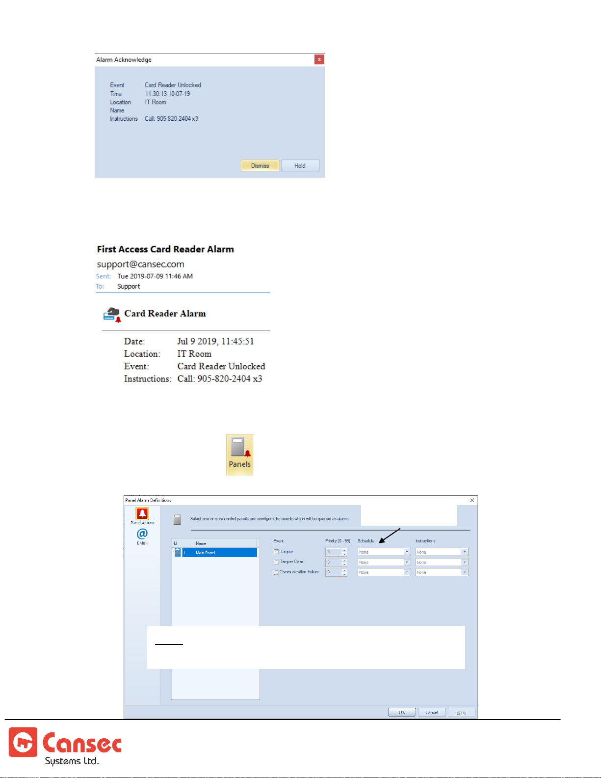
When an alarm occurs, it will be shown in the queue below
Double click on the event to either dismiss or hold it in the queue
First Access Page 44 of 88
Operator Guide October 2020 • Rev. 2.3
Page 45
Note: Email notifications are available in First Access
Advanced only.
System Schedule
If email notification is setup then an email notification will be sent like the sample
notification below.
Panel Alarm Notifications
1. Click Panels icon to launch Panel Alarm Definitions
First Access Page 45 of 88
Operator Guide October 2020 • Rev. 2.3
Page 46
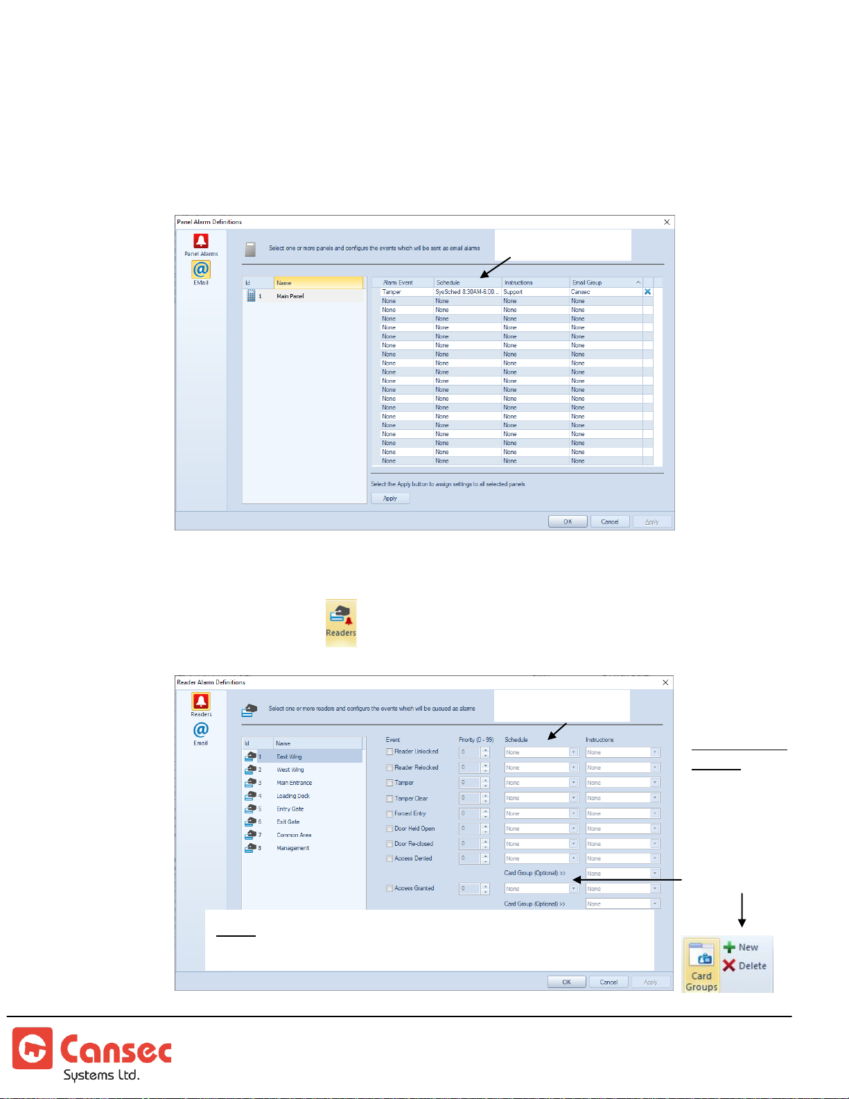
2. Select desired panel, event, priority, schedule and instruction to be displayed
Note: Email notifications are available in First Access
Advanced only.
System Schedule
System Schedule
Card Filtering
Option:
Notify only when
certain cards
access the door.
Card Groups
must be created.
in the alarm queue. The event sorting priority (0 to 99) defines the order in
which events are displayed in the alarm queue. (See Alarm Queue section)
3. Select Email to setup email notification. Click OK when done.
Reader Alarm Notifications
1. Click Readers icon
First Access Page 46 of 88
Operator Guide October 2020 • Rev. 2.3
Page 47
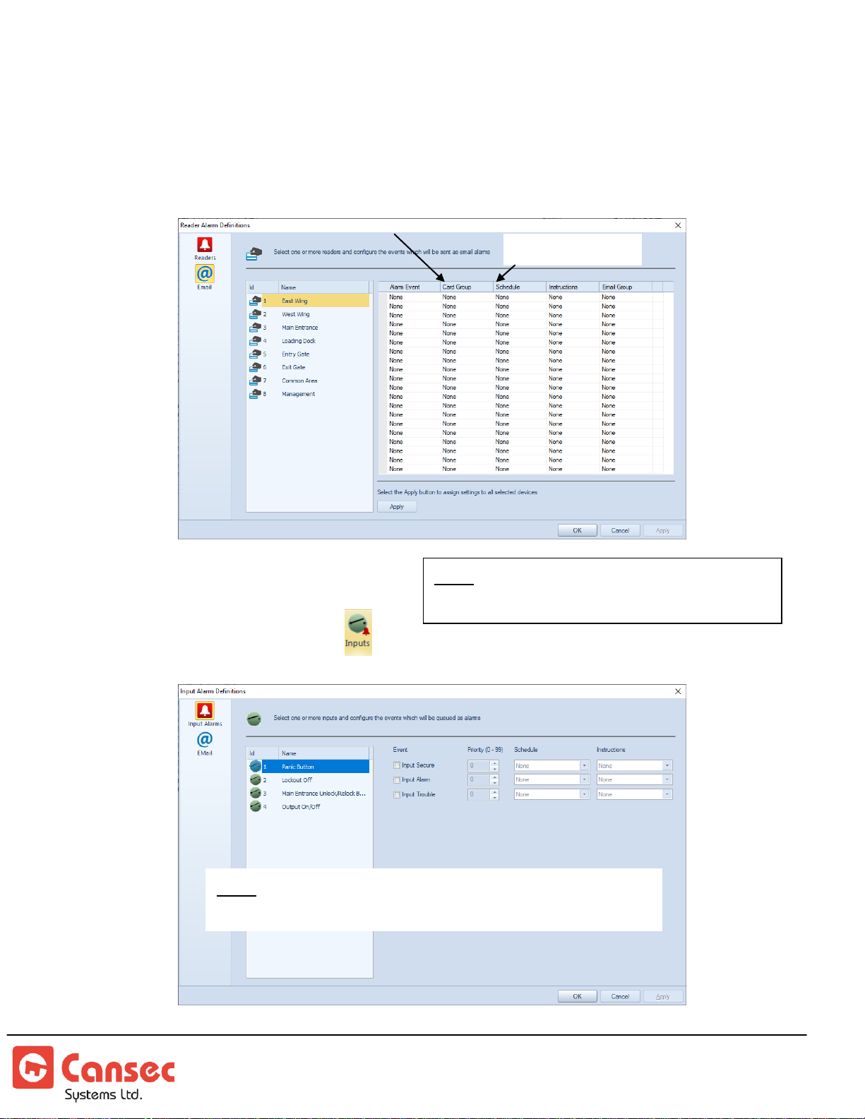
2. Select the desired reader, event, priority, schedule and instruction to be
Note: Email notifications are available in First Access
Advanced only.
System Schedule
Note: Auxiliary Input and Output are
available in First Access Advanced only.
Card filter
displayed in the alarm queue. The sorting priority (0 to 99) defines the order
in which events are displayed in the alarm queue.
3. Select Email to setup email notification. Click OK when done.
Input Alarm Notifications
1. Click on Inputs icon
First Access Page 47 of 88
Operator Guide October 2020 • Rev. 2.3
Page 48
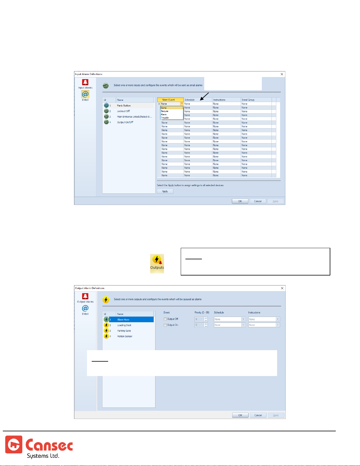
2. Select the desired input, event, priority, schedule and instruction to be
Note: Auxiliary Input and Output are
available in First Access Advanced only.
Note: Email notifications are available in First Access
Advanced only.
System Schedule
displayed in the alarm queue. The sorting priority (0 to 99) defines the order
in which events are displayed in the alarm queue.
3. Select Email to setup email notification. Click OK when done.
Output Alarm Notifications
1. Click on Outputs icon
First Access Page 48 of 88
Operator Guide October 2020 • Rev. 2.3
Page 49
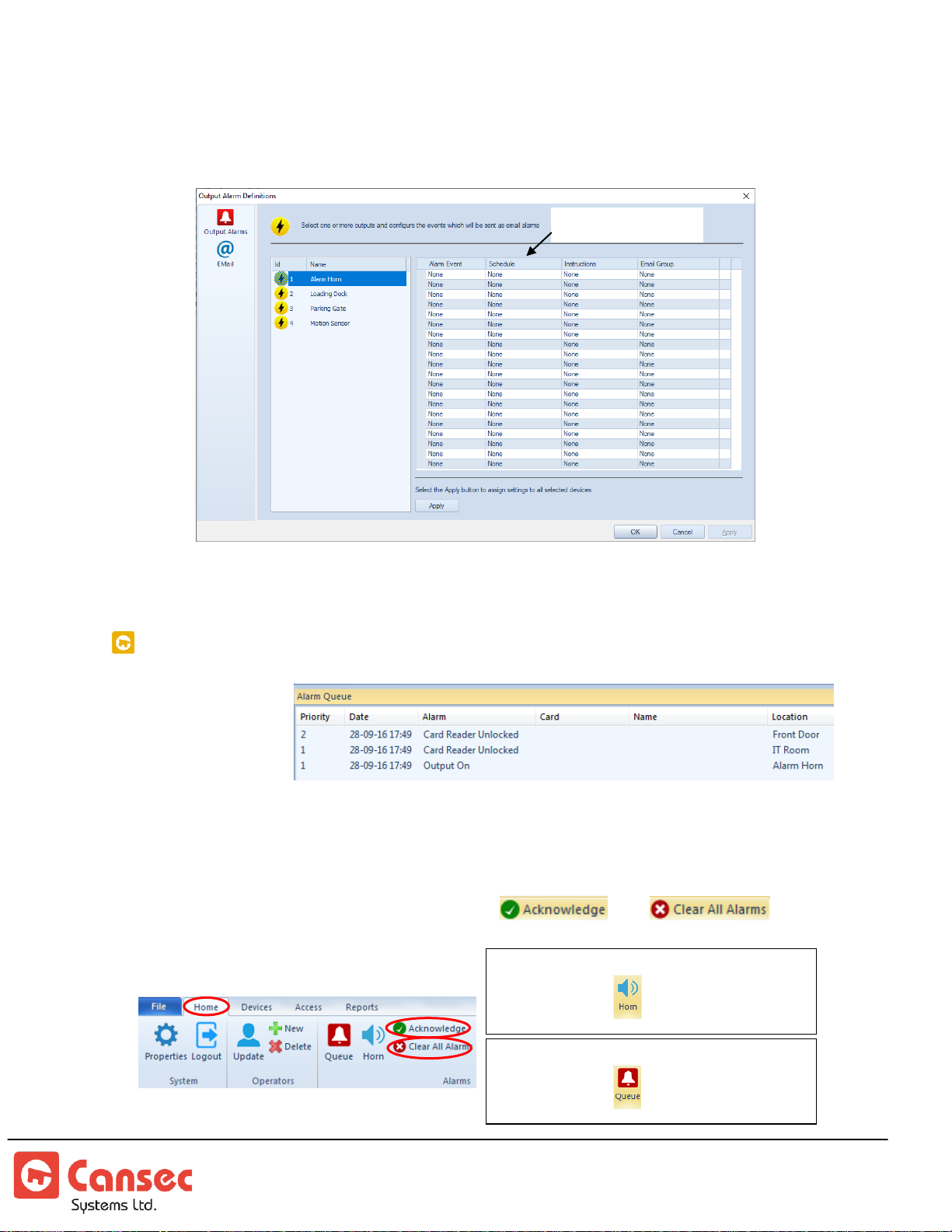
2. Select the desired output, event, priority, schedule and instruction to be
System Schedule
Alarm Queue can be enabled or disabled by
clicking the icon to toggle it on or off
Alarm Horn can be enabled or disabled by
clicking the icon to toggle it on or off
displayed in the alarm queue. The sorting priority (0 to 99) defines the order
in which events are displayed in the alarm queue.
3. Select Email to setup email notification. Click OK when done.
ALARM QUEUE
Alarm queue is
displayed at the
bottom of the
application. It
shows all the alarms related to readers, inputs and outputs
Individual alarm entry in the queue can be cleared or acknowledged by double
clicking on the selected entry. Selected individual alarm entry or all entries can also
be cleared by using the top menu buttons and
respectively.
First Access Page 49 of 88
Operator Guide October 2020 • Rev. 2.3
Page 50
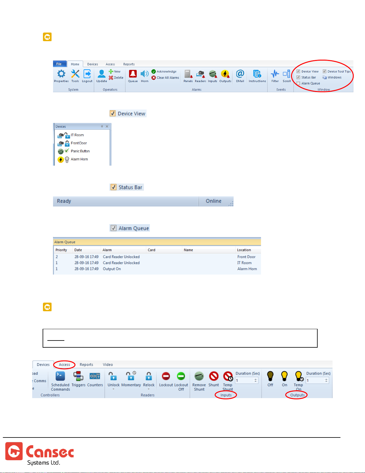
APPLICATION WINDOWS
Note: Auxiliary Input and Output are available in First Access Advanced only.
Select check box to show or hide Device View window
Select check box to show or hide Status Bar window
Select check box to show or hide Alarm Queue window
INPUT AND OUTPUT COMMANDS
First Access Page 50 of 88
Operator Guide October 2020 • Rev. 2.3
Page 51
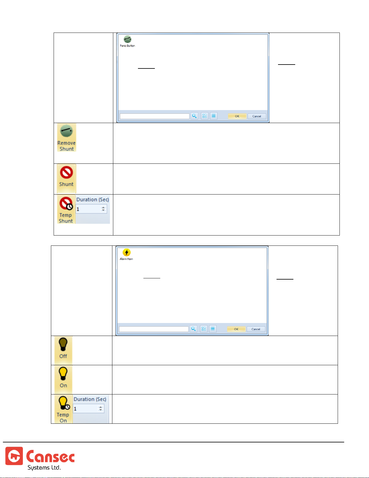
Input Points
Click and select an input point from the list to remove it from
being shunted. This allows the input events to be processed
normally by the controller or panel.
Click and select an input point from the list to shunt it. This
instructs the controller to ignore the input events.
Click and select an input point from the list to temporarily shunt
it for the entered duration in seconds. This instructs the
controller to temporarily ignore the input events for the entered
duration.
Output Points
Click and select an output point from the list to turn it off.
Click and select an output point from the list to turn it on.
Click and select an output point from the list to temporarily turn
it on for the entered duration in seconds.
Note: Auxiliary Input and
Output are available in First
Access Advanced only.
Note: Auxiliary Input and
Output are available in First
Access Advanced only.
Note: Sample
input point
named Panic
Button
Note: Sample
output point
named Alarm
Horn
First Access Page 51 of 88
Operator Guide October 2020 • Rev. 2.3
Page 52
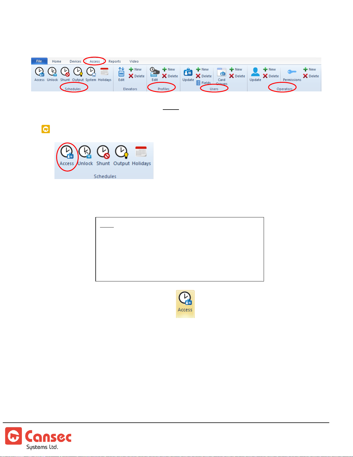
Step 4. Schedules, Profiles, Users and Operators
Note: There are 24 available intervals shared between weekdays
(7 days from Sunday to Saturday) and a holiday (1 day) for a
total of 8 days. Several intervals can be defined within a day, e.g.
Monday 9:00AM to12:59PM and Monday 1:00PM to
5:00PM. More than 3 intervals can be defined within a day as
long as the number of intervals for the 8 days (Mon to Sun and
Holiday) does not exceed 24.
Select Access from the top menu. Note: See Elevator section for more information.
ACCESS SCHEDULES
Access schedules specify when cardholders can use their credentials to access a
door.
1. Click the Access Schedule icon.
2. Select one of the 255 available access schedules.
3. Enter a name for the access schedule, e.g. 24/7 or Always.
4. Select an option for the Week Day. Double click on hour, minutes and
period (AM or PM) to modify times accordingly. Click OK when done.
First Access Page 52 of 88
Operator Guide October 2020 • Rev. 2.3
Page 53
UNLOCK SCHEDULES
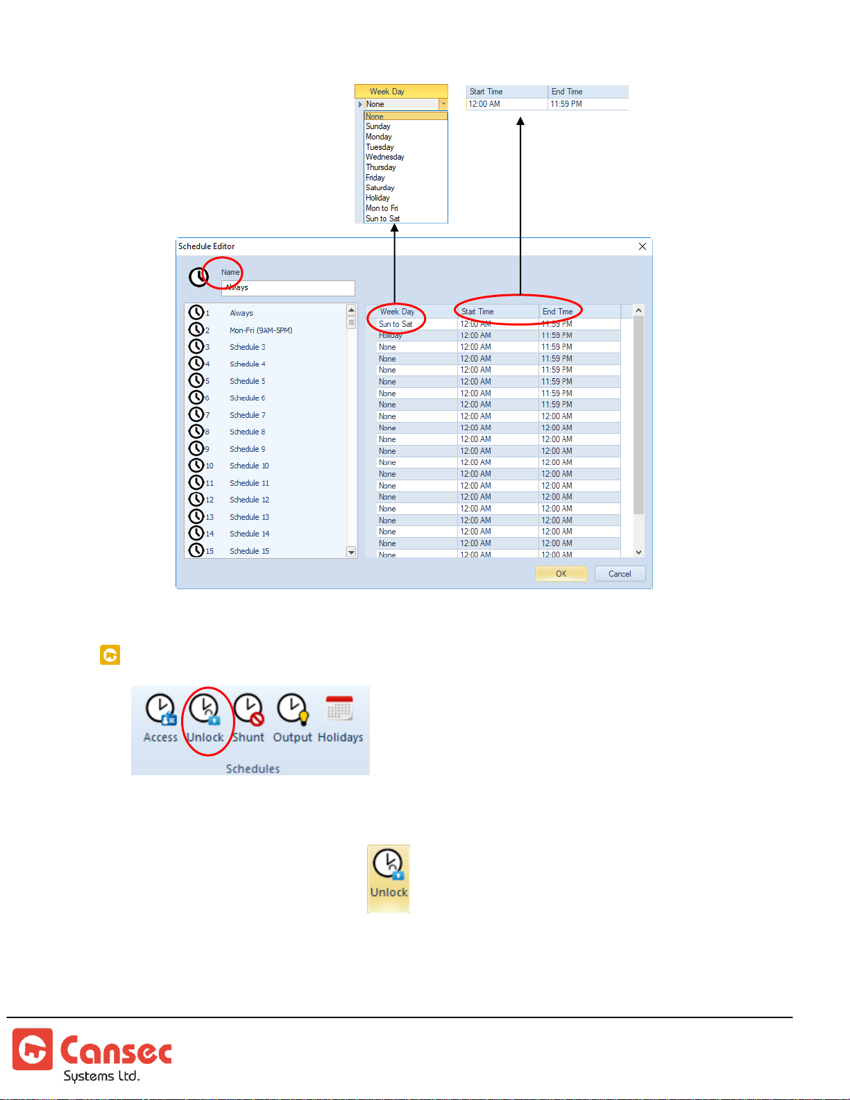
Unlock schedules are used to automatically unlock and relock a door at specified
times.
1. Click on the Unlock icon.
2. Select one of the 255 available unlock schedules.
3. Enter a name for the access schedule, e.g. M-F 8AM-5PM.
4. Select the day of the week. Double click on hour, minute and period (AM or
PM) to modify times accordingly.
First Access Page 53 of 88
Operator Guide October 2020 • Rev. 2.3
Page 54
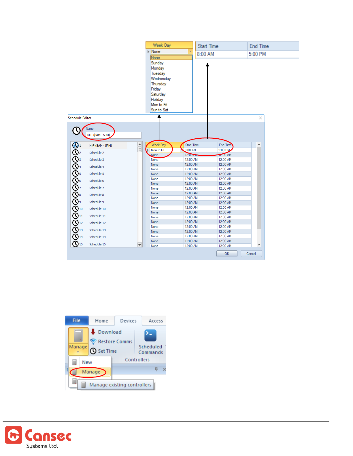
5. To assign an unlock schedule to a door, select Devices->Manage and select a
desired panel. Select Reader Definition and select an unlock schedule to assign
to that door.
First Access Page 54 of 88
Operator Guide October 2020 • Rev. 2.3
Page 55
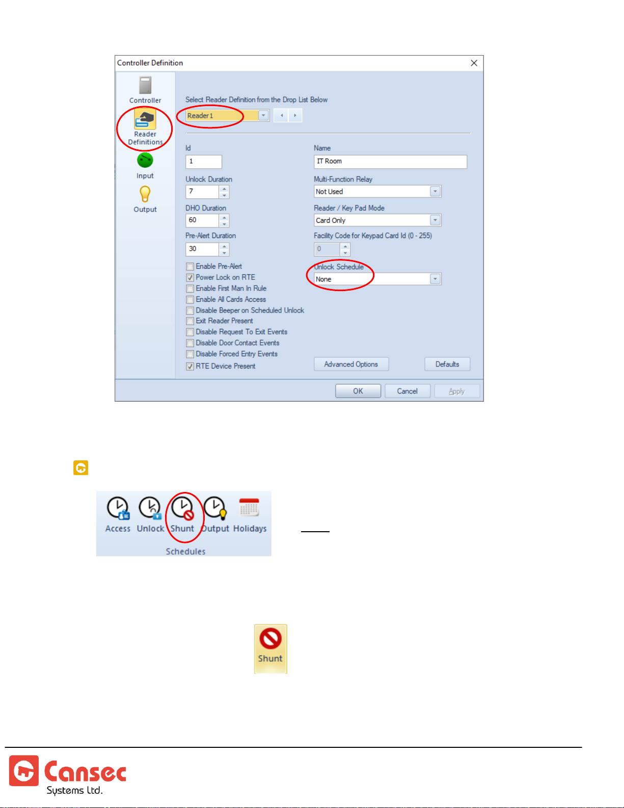
Note: Available in First Access Advanced only.
6. Click OK when done.
SHUNT SCHEDULES
Shunt schedules are used to instruct the controller or the panel when to process
and when to ignore input point events.
1. Click on the Shunt icon
2. Select one of the 255 available shunt schedules.
3. Enter a name for the shunt schedule, e.g. M-F (8AM-5PM)
4. Select the day of the week. Double click on hour, minute and period to modify
times accordingly.
First Access Page 55 of 88
Operator Guide October 2020 • Rev. 2.3
Page 56
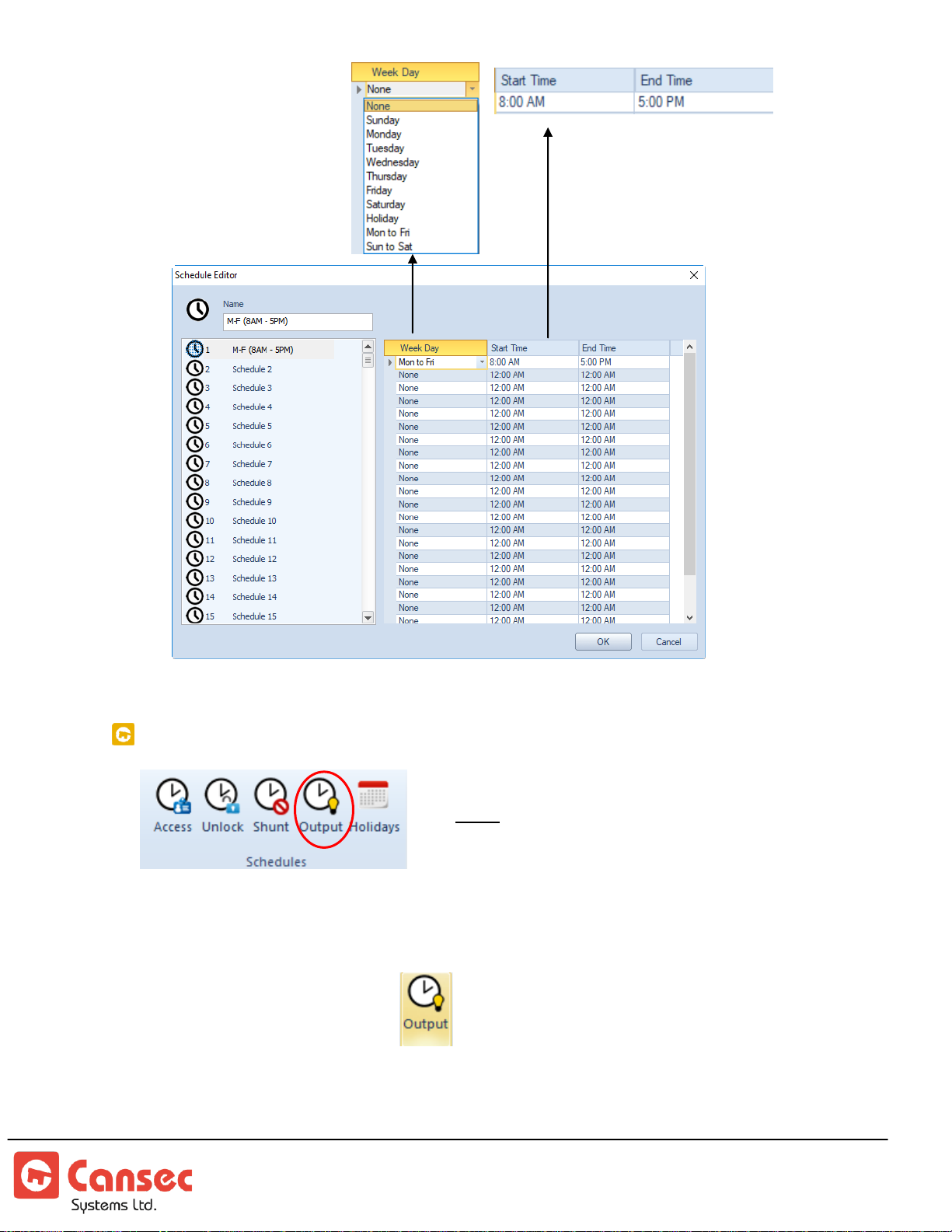
5. Click OK.
Note: Available in First Access Advanced only.
OUTPUT SCHEDULES
Output activation schedules are used to activate output points automatically during
specified times.
1. Click on the Output icon
2. Select one of the 255 available shunt schedules.
3. Enter a name for the Output schedule, e.g. M-F (8AM-5PM)
First Access Page 56 of 88
Operator Guide October 2020 • Rev. 2.3
Page 57
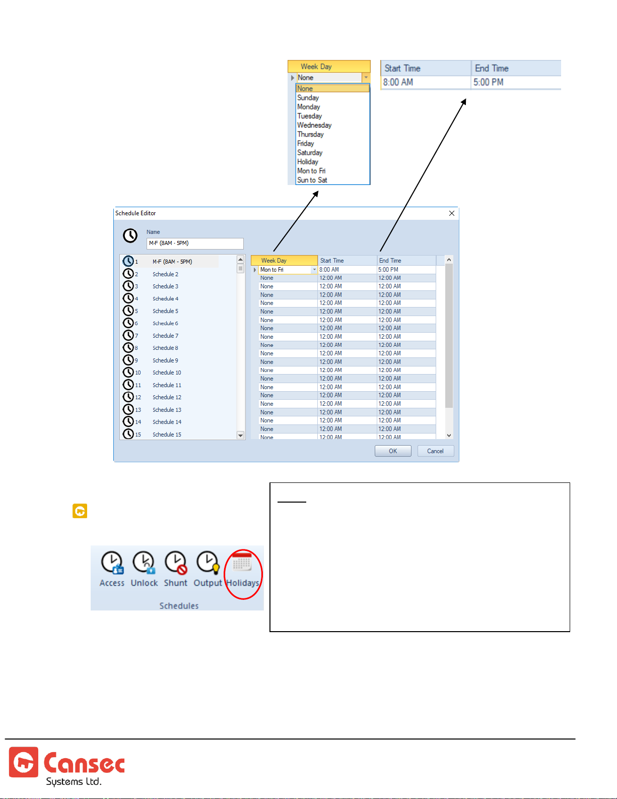
4. Select the day of the week.
Note
: A Holiday is not restricted to an individual day.
It can start at any time within the day, and end in the
same day or a different day at a different time. For
example, consider the case of a company which shuts
down for a week at noon on December 24th until
January 2nd of the New Year. This would be
accommodated using a holiday start date of December
24th at 12:00PM until January 2nd at 12:00AM.
Double click on hour,
minute and period to modify
times accordingly.
5. Click OK.
HOLIDAY SCHEDULES
First Access Page 57 of 88
Operator Guide October 2020 • Rev. 2.3
Holidays can be defined so that schedules like door unlock schedules and other
schedules do not take effect on days which are holidays. Holidays can be optionally
grouped into different sets for ease of assignment to different controllers, or they all
can share the same set. To create a new holiday:
Page 58
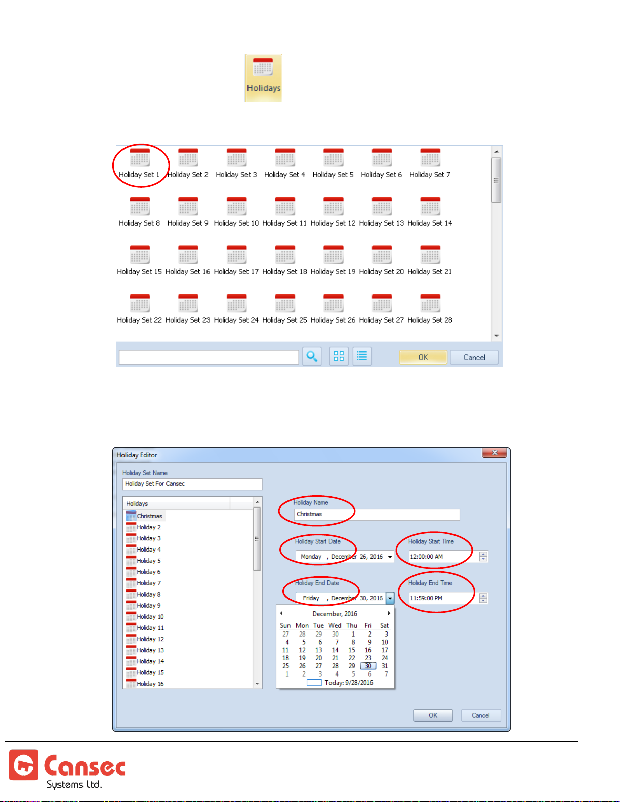
1. Click the Holiday icon.
2. Double click on one of the 100 available holiday sets.
3. Enter a name for the Holiday Set Name or leave as is. Enter a name for the
Holiday Name, e.g. Christmas.
First Access Page 58 of 88
Operator Guide October 2020 • Rev. 2.3
Page 59
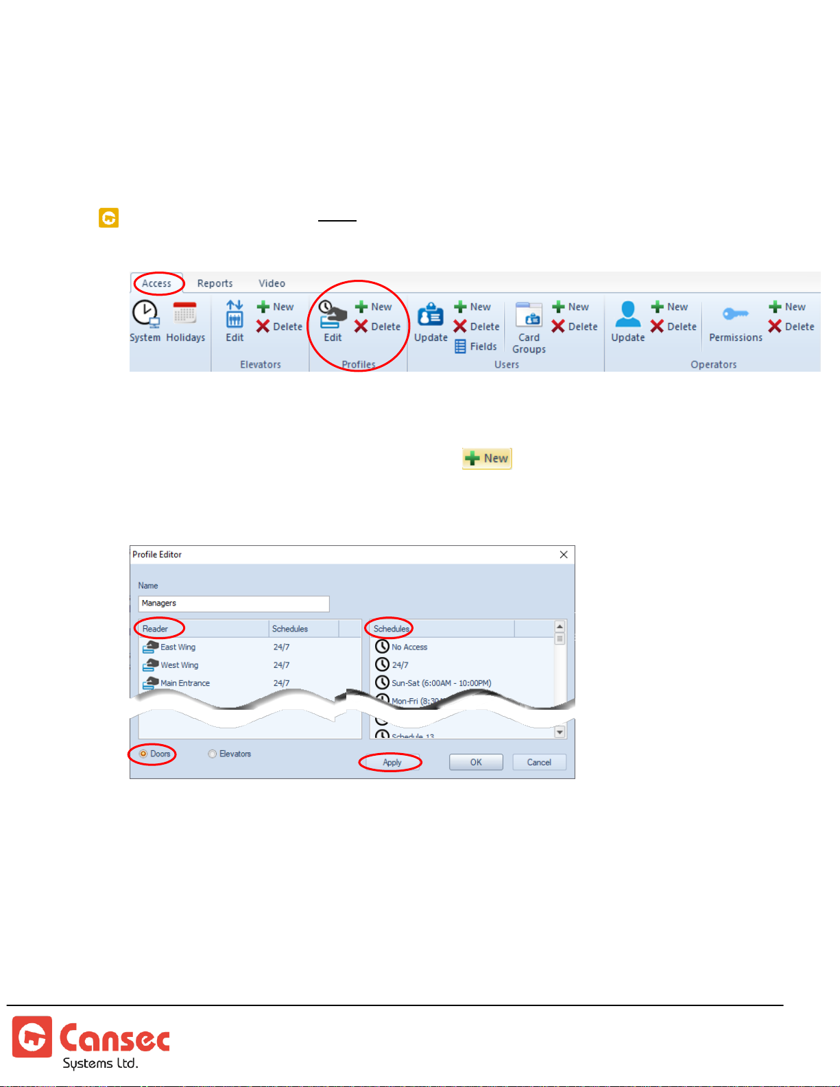
4. Use the arrows to select the month and the desired date for Holiday Start Date
Note: Operator permissions are available in First Access
Advanced only.
and enter the time for the Holiday Start Time.
5. Use the arrows to select the month and the desired date for Holiday End Date
and enter the time for the Holiday End Time. Click OK.
USER PROFILES
User profiles specify which doors a group of cardholders can access, and the time
during which access will be granted at each door. To create a new user profile:
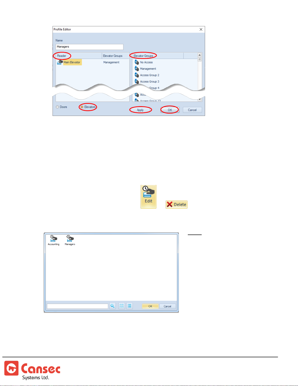
1. In Profiles section, click the +New icon.
2. Enter a name for the profile, e.g. Managers.
3. For Doors, select a reader on the left panel and select a schedule on the right
panel to assign to the reader. Click Apply. Repeat the same step for other
reader(s) if necessary. If there is no elevator then skip steps related to elevator and
click OK to finish.
4. For Elevators, select the elevator on the left panel and select an elevator group on
the right panel to assign to the elevator.
First Access Page 59 of 88
Operator Guide October 2020 • Rev. 2.3
Page 60
Note: To delete a profile, all users of
that profile must be assigned
to a different profile before it
can be deleted. See
Cardholder Report
section
for information about
assigning or migrating
multiple users to a different
profile.
5. Cardholders who belong to this profile will only be able to access the readers or
doors during the times specified in the associated access schedule. Likewise, if
elevator is assigned then cardholders in this profile can only access elevator floors
specified in that elevator group e.g. Management. See Elevator section for more
information about elevator group and how to define elevator groups.
6. Click OK when done.
To modify or delete a profile select or respectively. Select a desired
profile to be modified or deleted and click OK.
First Access Page 60 of 88
Operator Guide October 2020 • Rev. 2.3
Page 61
ADD CARDHOLDERS AND CARD GROUPS
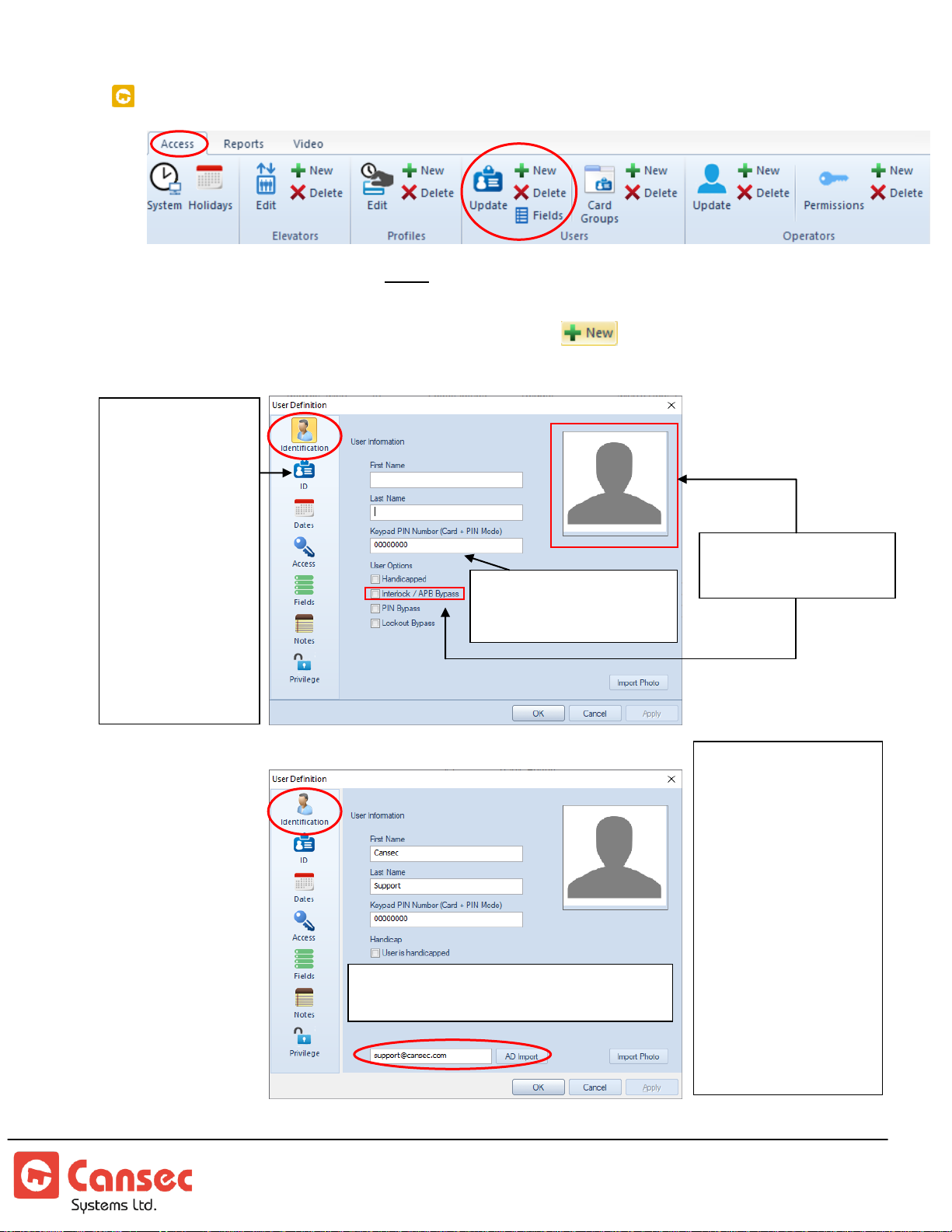
Active Directory (AD) Import is
available in First Access Advanced Only.
If applicable, use AD
Import to import all
attributes e.g. First
Name, Last Name,
Department, and
Phone Number etc…
of a user that will be
mapped to the user
fields and other fields.
In this example, we
use the email as a
unique attribute of
the user to query and
import all other
attributes of that user.
Note: Operator permissions are available in First Access
Advanced only.
Applicable for CARD + PIN
only. Ignore if not using
keypad for CARD + PIN
If using keypad
for entering card
number/PIN, but
not for CARD +
PIN, then use ID
field to enter
Facility / System
code and card
number or PIN.
Use keypad’s
manual to
program keypad
for use with
Cansec controllers
Available in First
Access Advanced only.
Card Holders
1. In the Users section, click the +New icon. beside the update button.
First Access Page 61 of 88
Operator Guide October 2020 • Rev. 2.3
Page 62
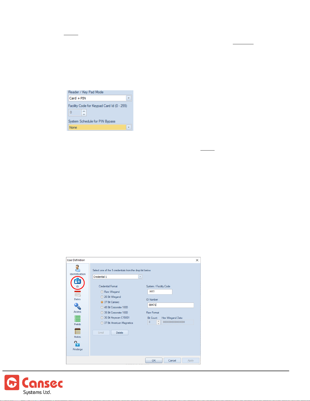
2. Note: Keypad PIN Number is applicable only if Card + PIN mode is used and
otherwise can be ignored. In this mode, the card must be presented followed by the
PIN number entered at the keypad. If Card + PIN is used, create/enter the PIN
number for this card. The PIN should be at least 4-digit long for up to a
maxium of 8-digit long. Obvious PIN shoud be avoided e.g. 1111, 1234
etc…There is also an option to bypass PIN requirement using PIN bypass
schedule seen in the reader configuration below.
3. If applicable select “User is handicapped”. The door operator will be energized
when this cardholder swipes his/her credential. Note: The door operator must
be installed and hooked up to the MAP1 panel using the Multi-Function relay which
must be set to Handicap Operator mode.
4. In the ID tab, select a credential from the drop-down list. Select a credential
format. For Raw Wiegand either present the credential to the enroller and
click Enroll or present the credential to a reader mounted at the door to get
the credential number displayed in the software and manually enter the
number in the Raw Format field. For other Wiegand formats, simply enter
the system or facility code and the number of the credential in the fields
System/Facility Code and ID Number respectively.
First Access Page 62 of 88
Operator Guide October 2020 • Rev. 2.3
Page 63
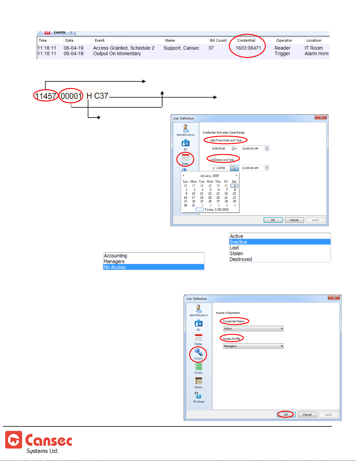
Other Sample Cansec Card
System/Facility Code: 11457
ID Number: 00001
HID Compatible
Cansec 37-bit
5. In the Dates tab, select the
dates and times for the
credential to be
automatically validated and
automatically expired.
6. In the Access tab, select a Credential Status
and select an Access Profile previously
created.
For new credentials, set the credential status to Active. Credentials that have
status set to Inactive, Lost,
Stolen or Destroyed will not be
granted access to any door.
First Access Page 63 of 88
Operator Guide October 2020 • Rev. 2.3
Page 64
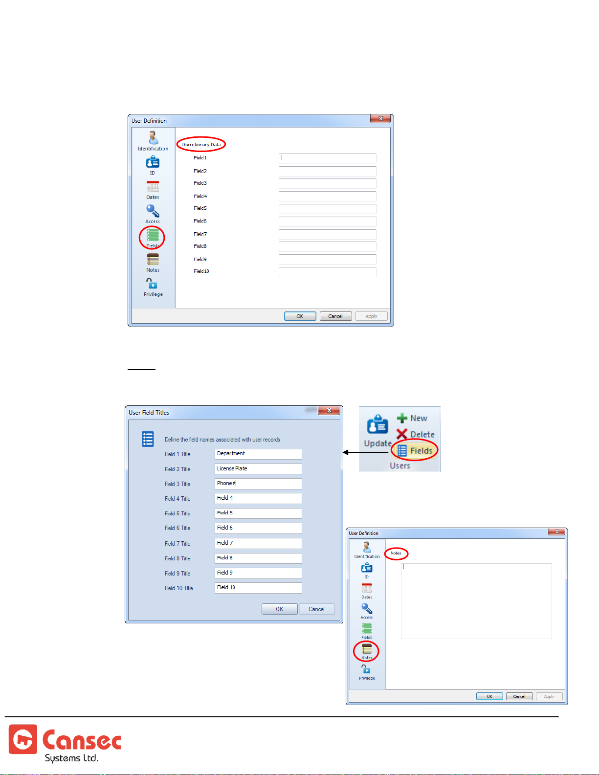
7. In the Fields tab, enter optional information in the 10 available fields, e.g.
Phone #, Parking lot #, Car license plate, etc.
Note: The field titles e.g. Field1, Field2 etc… can be renamed as desired by selecting
Fields
from the
Users
menu and modify the name of those fields accordingly.
8. In the Notes tab, enter optional notes.
First Access Page 64 of 88
Operator Guide October 2020 • Rev. 2.3
Page 65
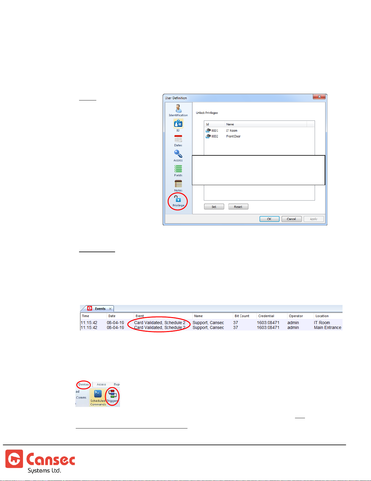
9. In the Privilege tab, optionally select door(s) that this cardholder is entitled to
Should be selectively assigned only to
individuals who require this function. It is
not intended to be assigned to all users.
toggle between locked and unlocked state when their credential is double
swiped at the card reader. Click Set, after doors have been selected, to assign
the privilege or click Reset to clear the privilege.
Note: Double swipe will
unlock the door in
a maintained
state and double
swipe again will
relock the door.
Single swipe will
momentarily
unlock the door
for the duration
that is set in the
unlock-time setting
of that door.
Important: The double-swipe privilege is optional and should be assigned only to
privileged cardholders e.g. Managers, Supervisors.
10. Click OK. Confirmation message(s) will be displayed in the Events panel.
Card Groups
Card groups provide an option to group a number of cardholders together in
a group which can be used in the unlock schedule or in the trigger feature
to determine which group can perform certain actions. There
are 100 card groups per controller and 75 cardholders per group. All
controllers share the same groups. See trigger section for more information
First Access Page 65 of 88
Operator Guide October 2020 • Rev. 2.3
Page 66
Note: Operator permissions are available in First Access Advanced only.
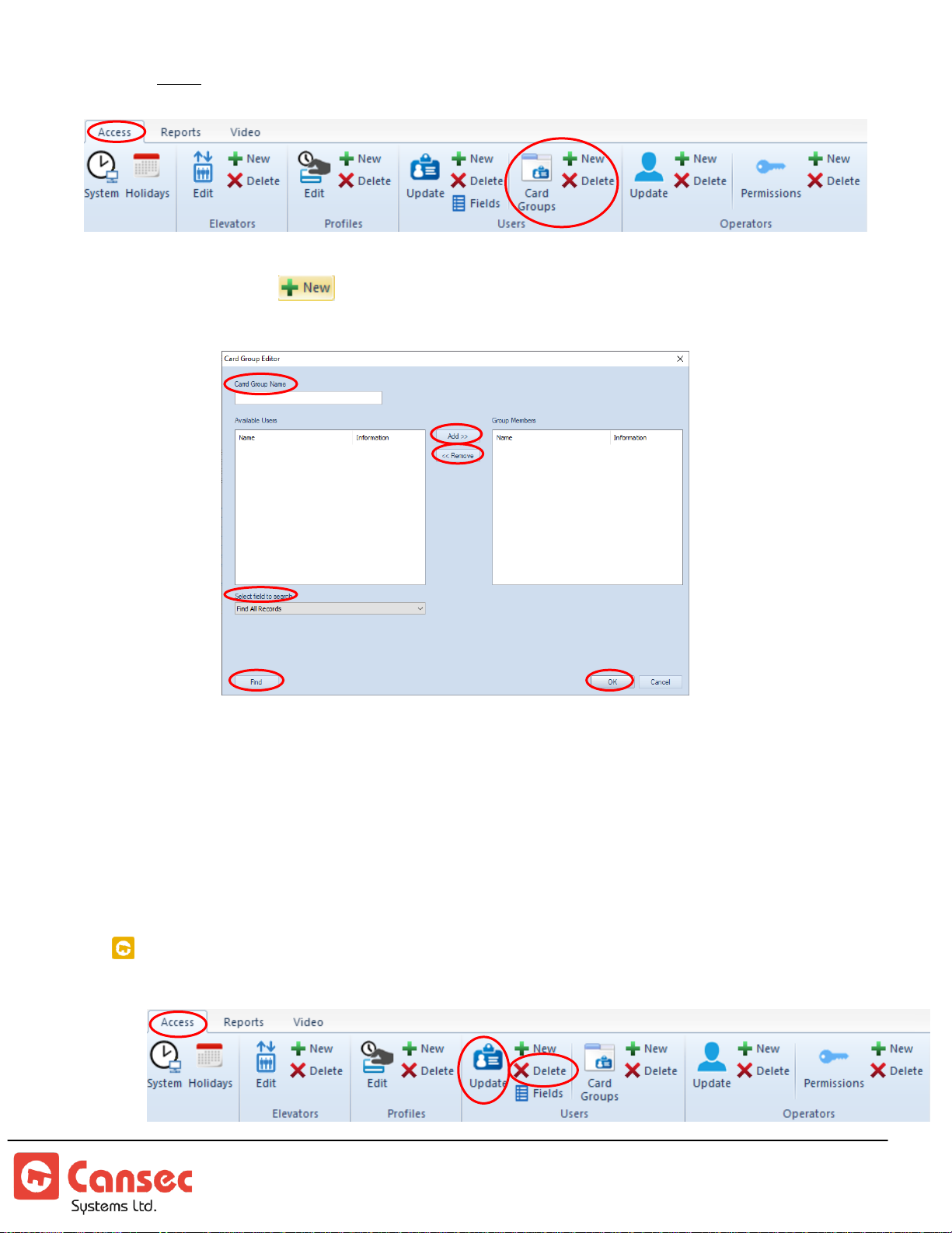
1. Click beside the Card Groups button
2. Enter a name for the group e.g. Managers etc…
3. Find certain cards or all cards using the filter then add those cards to the
groups. Click OK when done.
4. If more groups are required then repeat the same steps.
5. Select Card Groups button to edit or select Delete button to delete.
SEARCH, EDIT AND DELETE CARDHOLDER
First Access Page 66 of 88
Operator Guide October 2020 • Rev. 2.3
Page 67
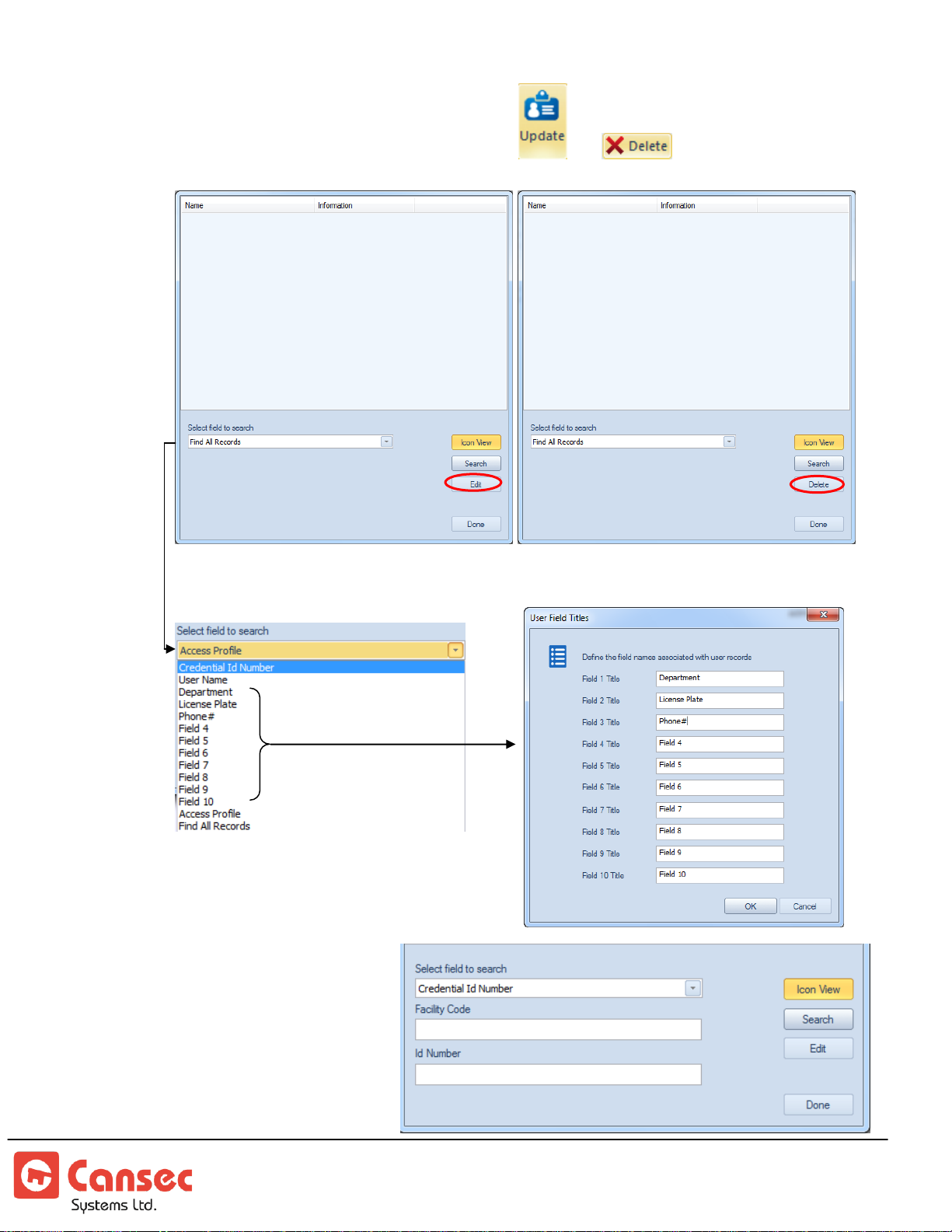
1. To edit or delete a cardholder, click the or button respectively.
2. Select a desired option to search for e.g. All Records, User Name etc....
3. To search records by
Credential ID select
option Credential Id
Number. If only Facility
Code is entered then the
result will be all
credentials having that
First Access Page 67 of 88
Operator Guide October 2020 • Rev. 2.3
Page 68
facility code. Similarly, if only Id Number is entered then the result will be all
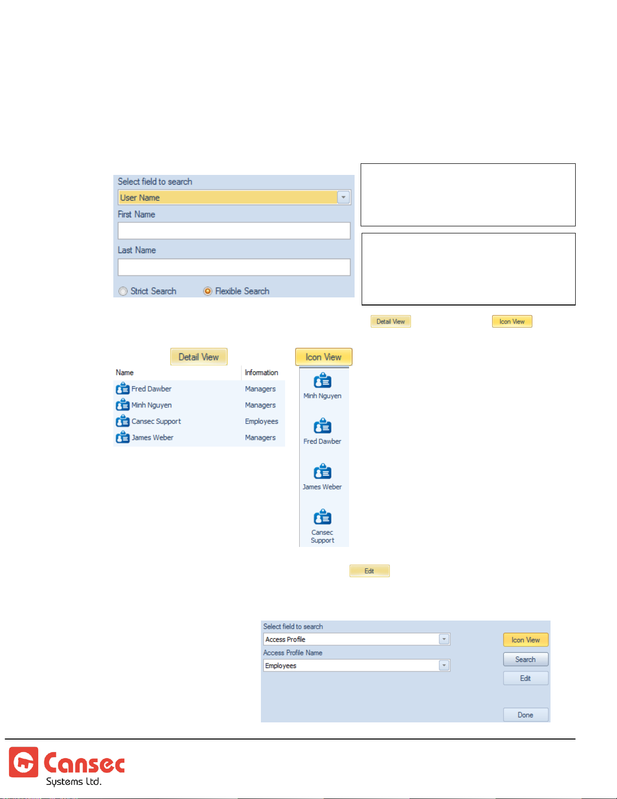
Strict Search: Requires full or complete
information to be entered e.g. John not Jo
will search for all first names having John.
Option applies to both First and Last Name.
Flexible Search: Allows partial information
to be entered e.g. Jo instead of John will
search for all first names having Jo as the
first 2 characters (John, Joe etc…). Option
applies to both First and Last Name.
credentials having that Id Number. However, if both Facility Code and Id Number
are entered then the result will just be one unique credential having that Facility
Code and Id Number
4. To search records by user name select User Name and enter either First Name
or Last Name or both to search.
5. Results can be viewed in either detailed mode or icon mode
6. To edit a record, select it and click button
7. To search by access profile, select Access Profile and select a desired profile to
search for e.g. Managers,
Employees etc…The result
will be all credentials
that belong to that
selected profile.
First Access Page 68 of 88
Operator Guide October 2020 • Rev. 2.3
Page 69
Note: Communication must be established between the
Note: Operator permissions are available in First
Access Advanced only.
Available
in First
Access
Advanced
only.
There is a default operator
named admin and the default
password is admin. The
default admin has full access
to the software.
In First Access Express, every
operator has full access to the
software.
Note: Manual logout
can be done by clicking
on logout button
software and controller for the modified or
deleted user record to be updated from the
controller. If there is no communication when
the modification or deletion is performed, the
user record will remain in the controller database. When communication is resumed, a
manual download from the software is required to update the controller again.
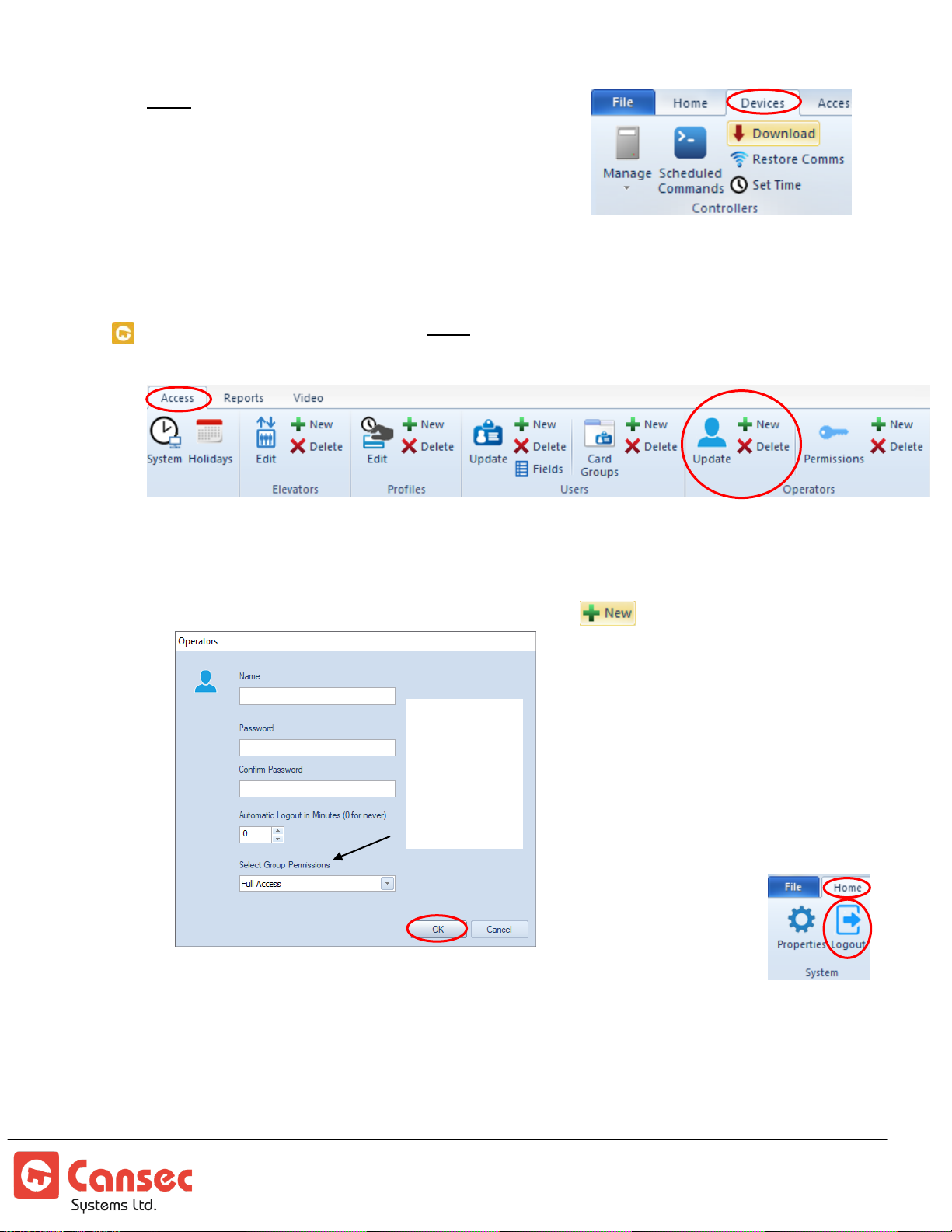
OPERATOR PROFILES
Operators are personnel who are authorized to login and manage the software and
controllers or panels.
1. In the Operators section, click the +New icon to create new operator.
2. Enter a short operator name e.g. Cansec.
3. Enter the password and enter it again on the next line to confirm.
4. Enter the idle time out in minutes to automatically log the operator out of the
software. Enter 0 for the software not to log out at all.
5. For First Access Advanced only, select an appropriate group to assign to the
First Access Page 69 of 88
Operator Guide October 2020 • Rev. 2.3
operator. See Operator Group Permission section.
Page 70
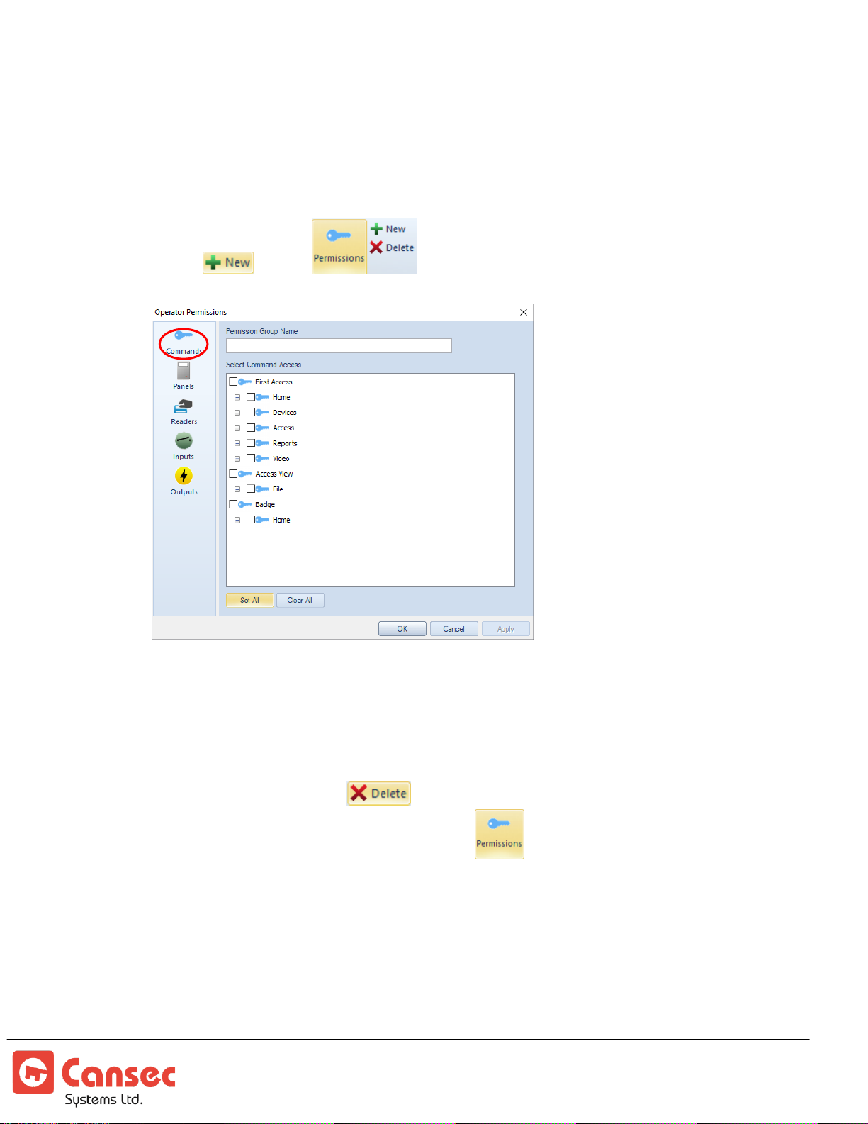
Operator Group Permission
Select commands alone do not
allow commands to apply to
anything. Devices must also be
selected for the commands to be
applied to
Video and Badge are add-on
software which must be
purchased separately. Video
deals with NVR integration and
Badge deals with photo badge.
Operator group permissions provide options to create different operator groups with
individual permissions for devices and commands. There is a default operator group
called Full Access which has all permissions assigned.
1. Select from to create a new group.
2. Enter a name for the group e.g. Restricted or HR or Security Guard etc…
3. Select desired commands and panels, readers, inputs and outputs points that you
would like operators to have access to.
4. Click OK to save. If necessary, follow the same steps above to create multiple
groups with different permissions.
5. To delete a group, select then select a desired group to delete.
6. To modify permissions for a group select then select a desired group to
modify permissions.
First Access Page 70 of 88
Operator Guide October 2020 • Rev. 2.3
Page 71
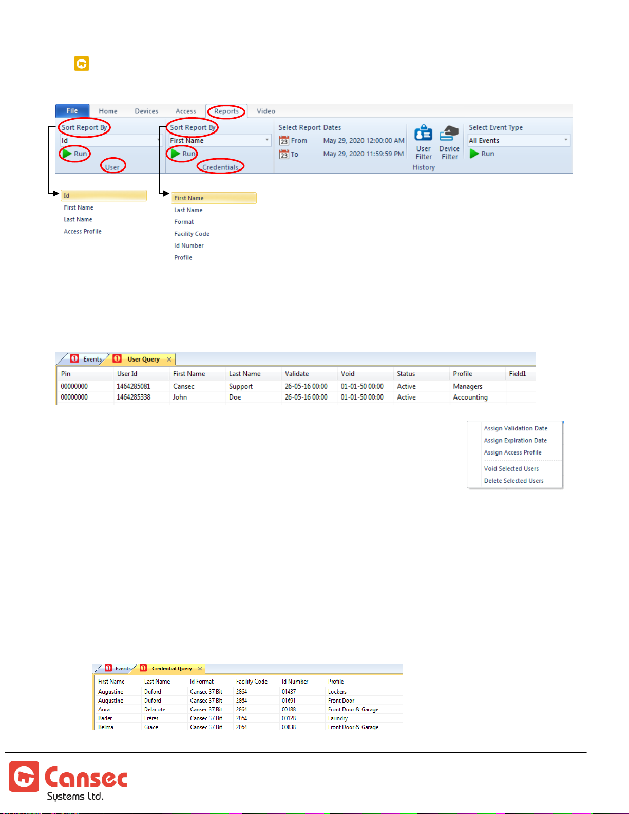
CARDHOLDER AND CREDENTIAL REPORT
There are different sorting options available when
generating cardholder or credential report. Sorting
options include:
User Report – display all the users
1. Pick the User then select a desired sorting option.
2. Click Run.
Optionally, select a cardholder or select multiple cardholders and right
click to display a pop-up menu from which quick commands can be
performed. This can be used to assign multiple cardholders to a
common validation date, expiration date or to a common access
profile. Multiple cardholders can also be:
Voided – Credentials’ status are set to Inactive. Access is not granted at any door. However,
the records are kept in the database for the purpose of potential re-activation.
Deleted – The records are permanently deleted from the database and from the controllers.
Access is not granted at any door.
Credential Report – display all the credentials of the users
3. Pick the Credentials then select a desired sorting option.
4. Click Run.
First Access Page 71 of 88
Operator Guide October 2020 • Rev. 2.3
Page 72
Step 5. History and Audit Report
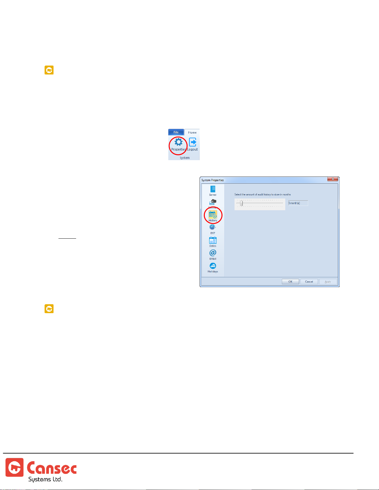
CONFIGURE HISTORY RETENTION
The First Access software records all events on the computer's hard drive. Because
First Access is a “real-time” system, these events are constantly being recorded in
the Microsoft SQL Database. To specify the retention period, perform the following
steps:
1. Launch System Properties
2. Select History tab.
3. Use the slider to specify retention
period in a month. Click OK
when done.
Note: Once a month the system will scan
and discard any history entry older
than the specified month.
ON-BOARD AUDIT EVENT STORAGE
The MAP1 control panel is capable of storing a maximum of 10,000 events in its
memory when the panel does not communicate with the software. When 10,000
events have been reached, new events will replace the oldest events. When the
panel resumes it communication, all old and new events are sent to the computer
in real time freeing its memory for storage when the communication is not
established and panel goes offline. The panel must have a backup battery to prevent
all historical events from being lost from its volatile memory storage when a power
outage occurs. All other settings are saved in non-volatile memory storage.
First Access Page 72 of 88
Operator Guide October 2020 • Rev. 2.3
Page 73
VIEW AUDIT HISTORY
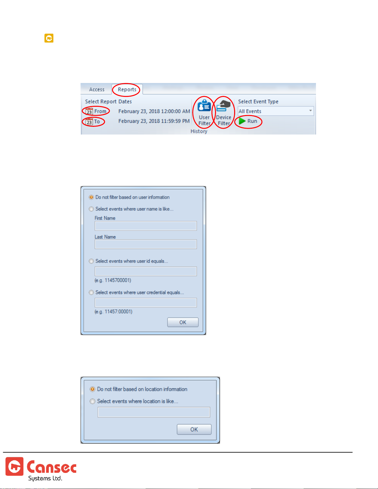
To view all audit history events stored in the database:
1. Select Report from the top main menu.
2. Select Month, Day and Year for From date.
3. Select Month, Day and Year for To date.
4. Optionally select User Filter to generate a report for a particular user.
5. Optionally select Device Filter and enter device name e.g. Front Door to
generate report for that door only.
First Access Page 73 of 88
Operator Guide October 2020 • Rev. 2.3
Page 74
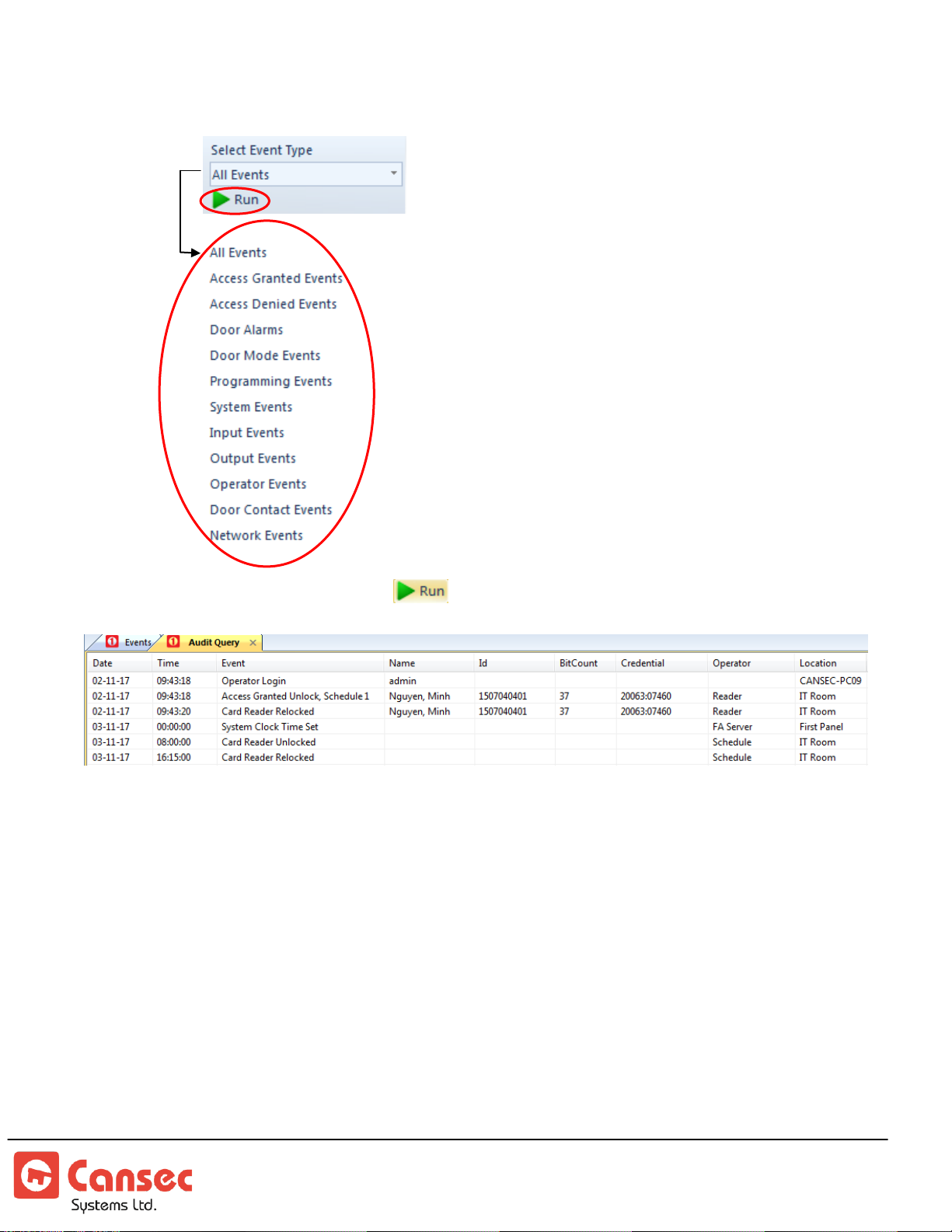
6. Select a filter for the Event Type.
7. Click the Run button.
First Access Page 74 of 88
Operator Guide October 2020 • Rev. 2.3
Page 75
Elevator
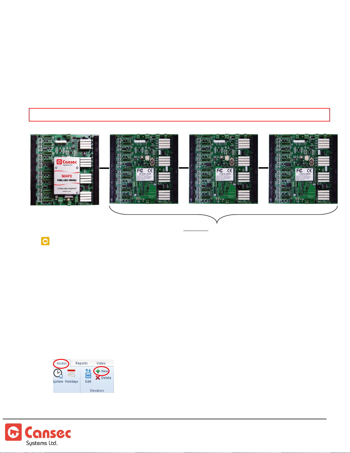
Elevator MAP2 Panel
H1000 Panel
H1000 Panel
H1000 Panel
Floors 1-16
Floors 17-32
Floors 49-64
Optional: H1000 Panels
Elevator MAP2 Panel must be provisioned by Cansec each time an additional add-on H1000 panel is added
The First Access software, both Express and Advanced versions, supports MAP2 panel
provisioned for elevator mode. The MAP1 panel does not support elevator mode.
The elevator MAP2 panel alone supports up to 16 floors. However, with the optional addon dedicated H1000 panels, the MAP2 panel supports up to a maximum of 64 floors.
FLOOR GROUPS, ACCESS GROUPS AND FLOOR-UNLOCK SCHEDULE
The elevator floor group defines a set of floors that an elevator handles. The access
group defines who may access those floors. The optional floor-unlock schedule defines
when selected floors may be freely accessible to everyone.
Typically, there is just one floor group and one elevator, but there are cases where
multiple elevators are used to serve different floor sets e.g. elevator one serves floors 1
to 32 while elevator two serves floors 33 to 64.
1. If not already created then create a new elevator floor group from the top menu
Access under the Elevators sections
2. Enter a name for the floor group e.g. Floor Group One
First Access Page 75 of 88
Operator Guide October 2020 • Rev. 2.3
Page 76
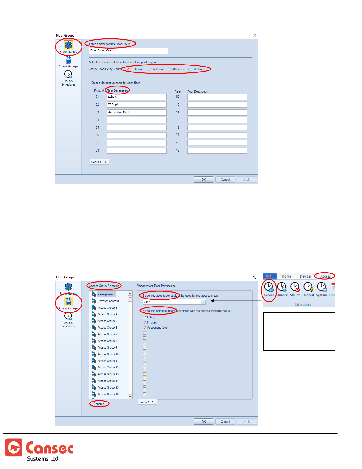
Access schedule
define day and time
that access is granted
to the selected floors
3. Select the desired number of floors (16, 32, 48 or 64) that this elevator group will
support and name each floor accordingly.
4. Select an Access Group then select a desired access schedule and floors that this
access group is permitted to access. Rename the group as desired e.g. IT Department.
If necessary, select another access group and repeat similar steps to assign access
privilege for that group.
First Access Page 76 of 88
Operator Guide October 2020 • Rev. 2.3
Page 77
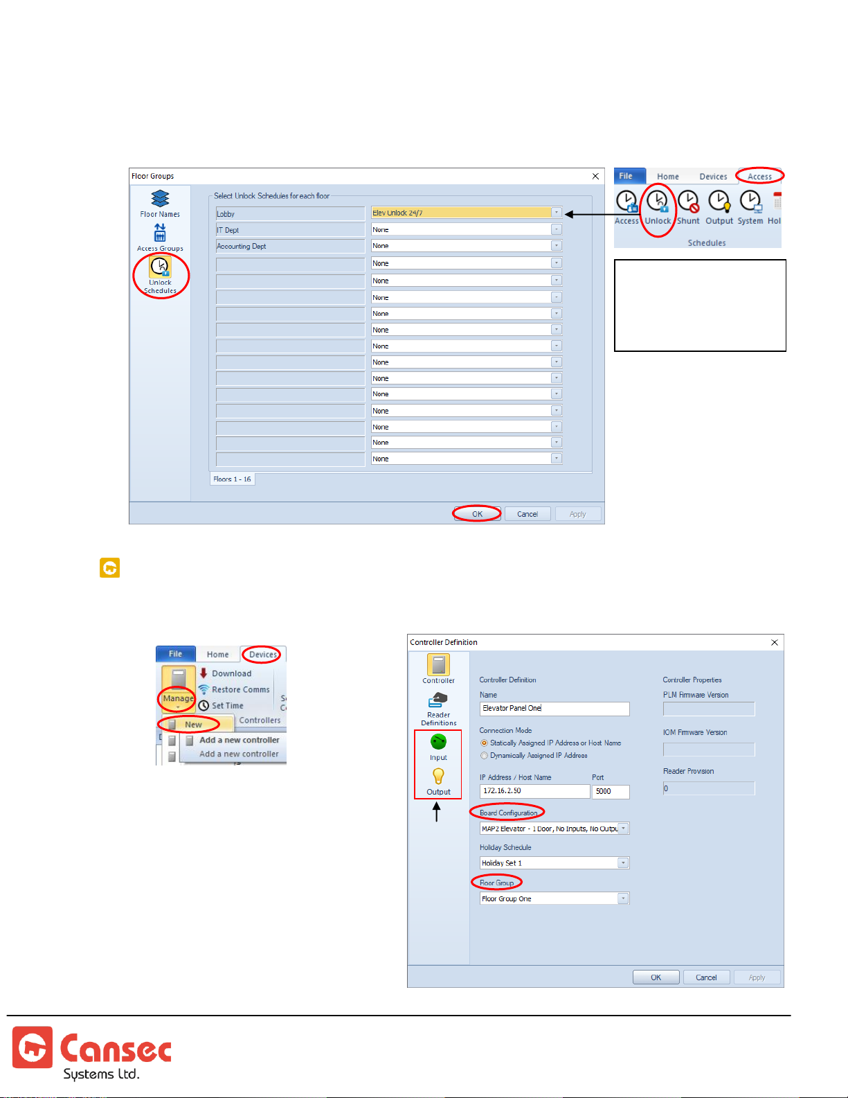
5. If a floor is required to unlock for the purpose of free access then select Unlock
Ignore
Input &
Output
Input & Output are available in First Access Advanced
only. Not applicable in elevator mode
Unlock schedule
define day and time
that the selected floors
is freely accessible
Schedules. Next, select a desired floor and choose an unlock schedule to assign to
it. If necessary, repeat similar steps for other floors.
ADD ELEVATOR PANEL
1. Select Devices -> Managed -> New from the top menu
2. Name the panel e.g. Elevator
Panel One etc…
3. Select appropriate connection
mode.
4. Select MAP2 Elevator for board
configuration and assign it a
floor group that it will handle.
First Access Page 77 of 88
Operator Guide October 2020 • Rev. 2.3
Page 78
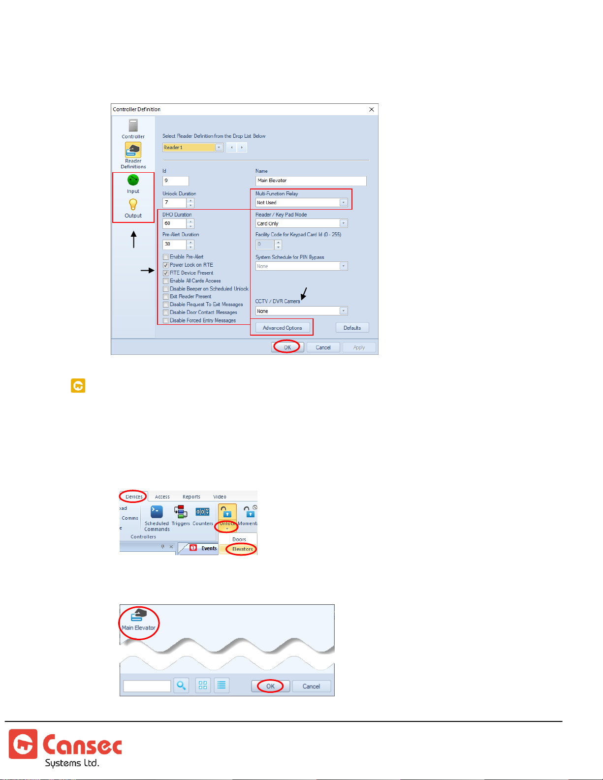
5. Enter a name for the reader e.g. Main Elevator. Ignore options that are related to
Add-on option
Ignore
these
options
doors e.g. Multi-Function Relay, DHO duration etc… Click OK when done.
MANAGE ELEVATOR FLOORS
Floor Unlock
1. Select Devices and select the down arrow of the Unlock button then select
Elevators.
2. Select a desired elevator.
First Access Page 78 of 88
Operator Guide October 2020 • Rev. 2.3
Page 79
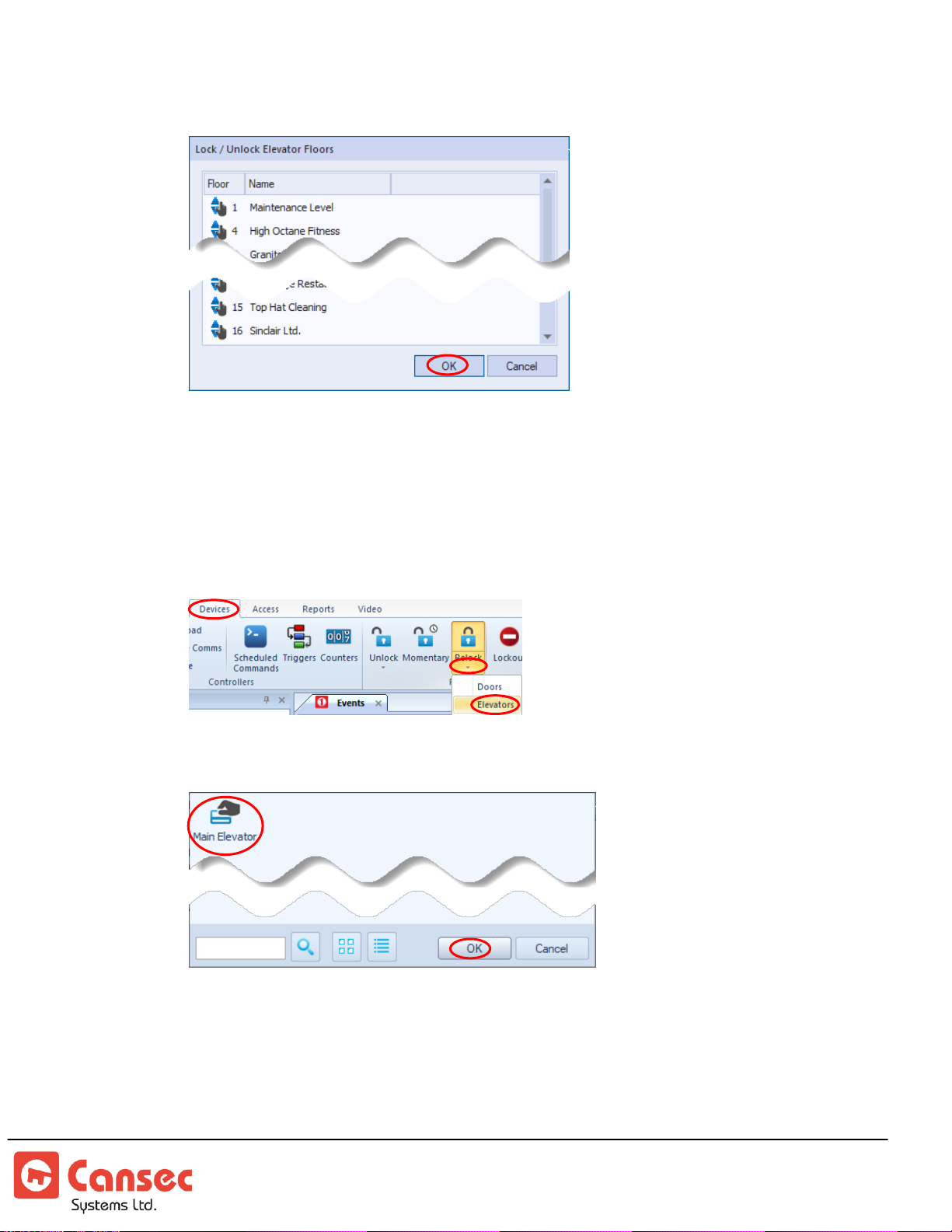
3. Select floors to be unlocked.
4. Click OK when done.
Floor Relock
1. Select Devices and select the down arrow of the Relock button then select
Elevators.
2. Select a desired elevator.
3. Select currently unlocked floors to relock them.
First Access Page 79 of 88
Operator Guide October 2020 • Rev. 2.3
Page 80
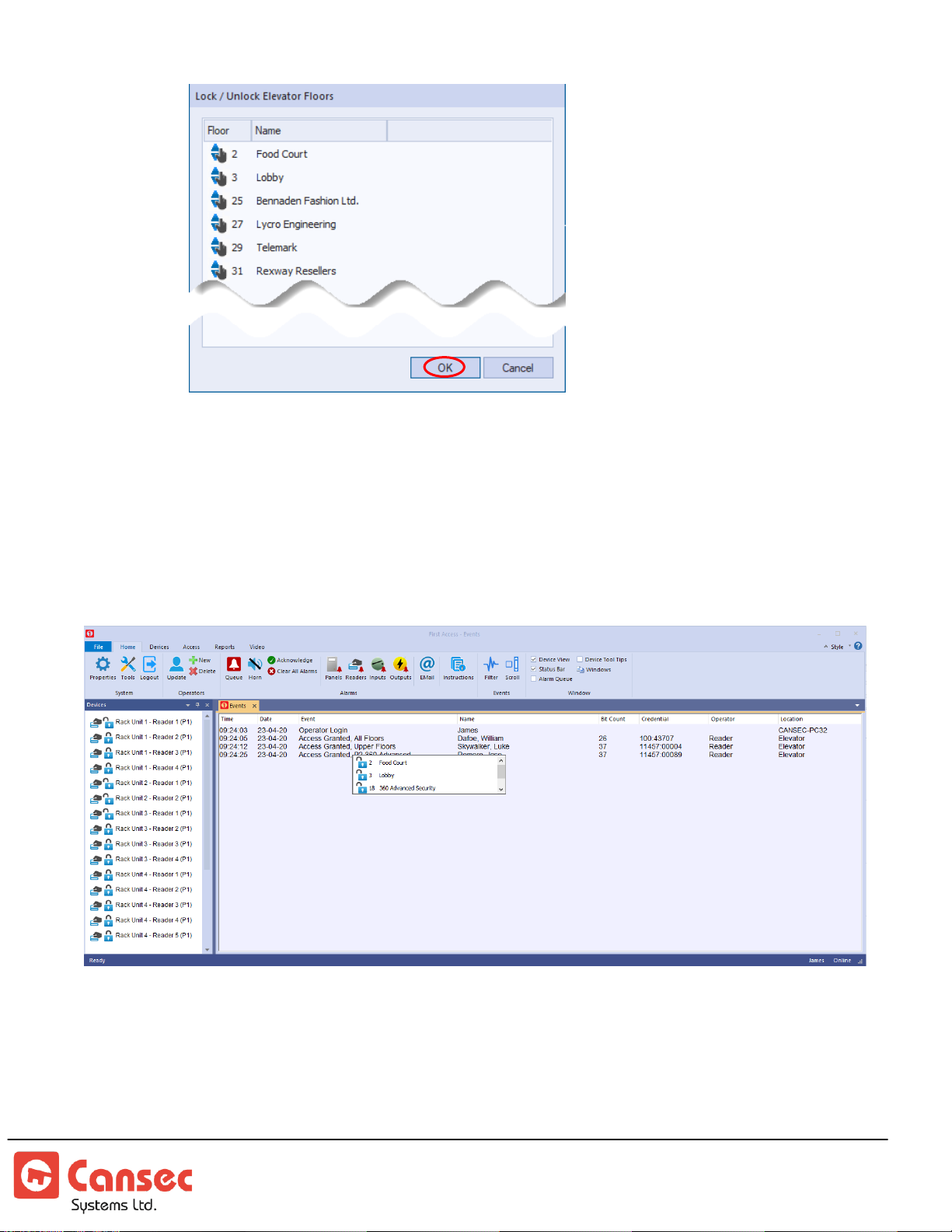
4. Click OK when done.
Access Granted Event
When an access-granted event for the elevator is displayed in the First Access
software, you may click on that event to show the floors that were unlocked by
that access granted event.
First Access Page 80 of 88
Operator Guide October 2020 • Rev. 2.3
Page 81
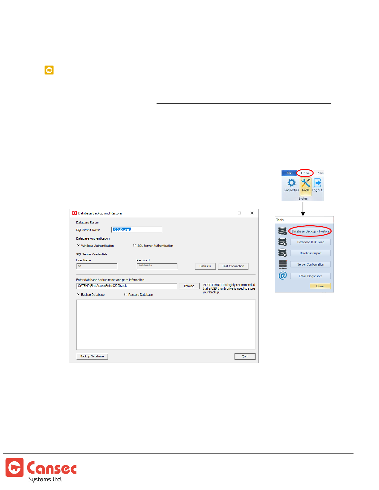
Appendix
DATABASE BACKUP UTILITY
The Database Backup Utility provides options to backup the database or to restore
the database from a backup. The utility is only applicable for the Microsoft SQL
database that was installed by First Access software. It’s required that the backup be
done regularly and preferably by an IT personnel or database administrator and
stored offsite for recovery when needed.
1. Launch Database Backup/Restore from the Tools menu.
2. The server name and SQL instance is normally .\SQLExpress but if you have
used other instance name e.g. .\SQLFA then enter the
appropriate name.
3. Select either Windows or SQL Server Authentication.
4. To backup the database, select Backup Database option and click Browse to
select the location to save the backup file to. Click Backup Database button
5. To restore the database, select Restore Database option and click Browse to
select the location where the backup file was saved to. Select the back file and
click Restore Database button.
6. Select Quit when done.
First Access Page 81 of 88
Operator Guide October 2020 • Rev. 2.3
Page 82
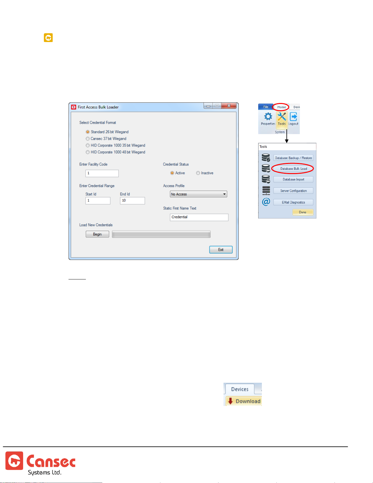
BULK CREDENTIAL LOAD UTILITY
The Bulk Credential Load Utility provides an option to load several credentials of
certain format without the need to load one credential at a time.
1. Launch Database Bulk Load from the Tools menu.
Note: The information about your credential e.g. format, system/facility code and
credential range are usually printed on the box. If unsure, contact your dealer or the place
where you have purchased your credential from.
2. Select the format of your credentials and enter the Start Id and End Id. Select
the status either Active, for the credentials to be active immediately, or Inactive
which can later be set to Active. Select a desired Access Profile and enter a
generic name for all credentials. The name can later be modified to the actual
name of the credential owner before or as credentials are handed out to the
owner.
3. Select Begin to load all credentials.
4. Follow the prompt to download to the panels
5. If more than one types or formats of credentials are available then repeat the
same steps to load them. Otherwise select Exit.
First Access Page 82 of 88
Operator Guide October 2020 • Rev. 2.3
Page 83
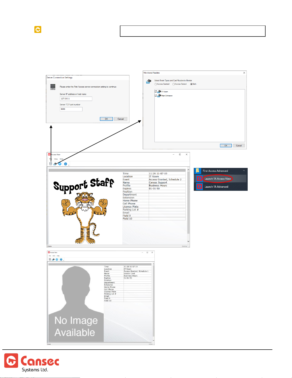
FA ACCESS VIEW
FA Access View is available in First Access Advanced Only.
The FA Access View utility provides an option to view access events of cardholders
from selected readers. The event can either be access granted event or access denied
event or both events. If the cardholder has an image imported to his/her record
then it will be shown accordingly.
First Access Page 83 of 88
Operator Guide October 2020 • Rev. 2.3
Page 84
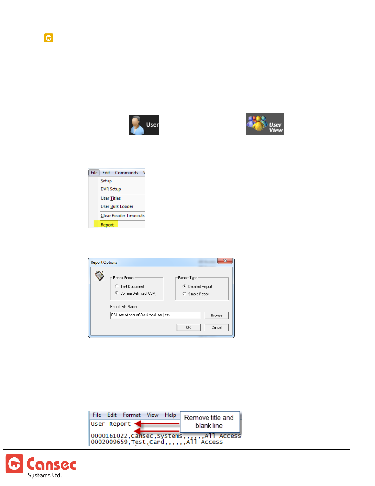
FIRST ACCESS IMPORT UTILITY
The Import Utility provides an option to import the user database, exported to a csv
file from either SmartLock Pro, SmartLock Pro Plus or Huricane software, into the
First Access database.
Export from SmartLock Pro or SmartLock Pro Plus
1. Select User (Pro Plus) or User View (Pro) from the
left panel.
2. To top left menu, select File->Report
3. Select “Comma Delimited (CSV) and select “Detailed Report”
4. Click Browse to select a location to save the csv report file to. Enter a
name for the file e.g. ProPlusUsers.csv
5. Click OK when done.
6. Use Notepad (Do not use Excel application because it removes leading zeros from
card number). Open the file and remove the title and any blank line.
First Access Page 84 of 88
Operator Guide October 2020 • Rev. 2.3
Page 85
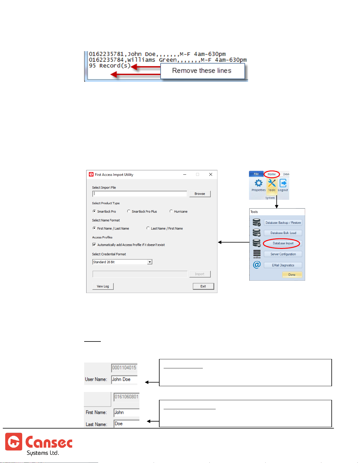
7. At the end of the file, remove the record counter and any blank line.
SmartLock Pro: One field for both First Name and Last Name
First Name followed by Last Name or
Last Name followed by First Name
SmartLock Pro Plus:
First Name and Last Name have their own fields.
8. Save the file to get it ready for import.
Import to First Accesss
1. Launch Database Import from the Tools menu once the csv file has been
exported from either Pro or Pro Plus.
2. Click Browse to locate and select the exported csv file.
3. Select the product type e.g. SmartLock Pro or SmartLock Pro Plus that the csv
file was exported from.
Note: The Name Format selection is applicable to SmartLock Pro only since Pro
has only one field for both First Name and Last Name.
First Access Page 85 of 88
Operator Guide October 2020 • Rev. 2.3
Page 86
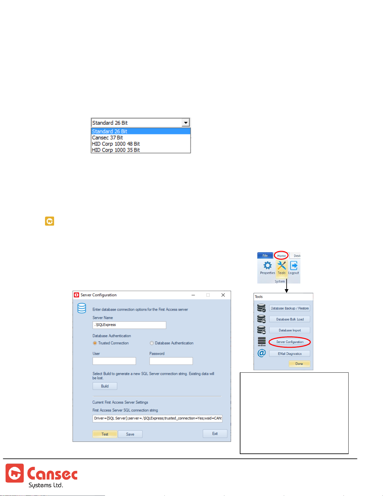
4. For SmartLock Pro, select if the User Name field contains First Name
The configuration should be
done by IT personnel or by
database administrator. The
default configurations are
performed during the software
installation. As such, these steps
should be performed only when
there is a change to the server
e.g. a migration of the server.
followed by Last Name or Last Name followed by First Name. This way,
the names will be imported accordingly into First Access.
5. Select the credential format that the users have. Usually, all users carry the
same credential format. If users carry different formats then the csv file
must be edited to group users having the same format together, save them
in different csv files and import one file at a time.
6. Click Import to import the exported csv file.
7. Click View Log to review any error message that may have happened
during the import.
8. Click Exit when done.
SQL SERVER CONNECTION CONFIGURATION UTILITY
The Server Configuration Utility provides an option to configure or modify the
SQL server connection information.
1. Launch Server Configuration from the Tools menu.
First Access Page 86 of 88
Operator Guide October 2020 • Rev. 2.3
Page 87
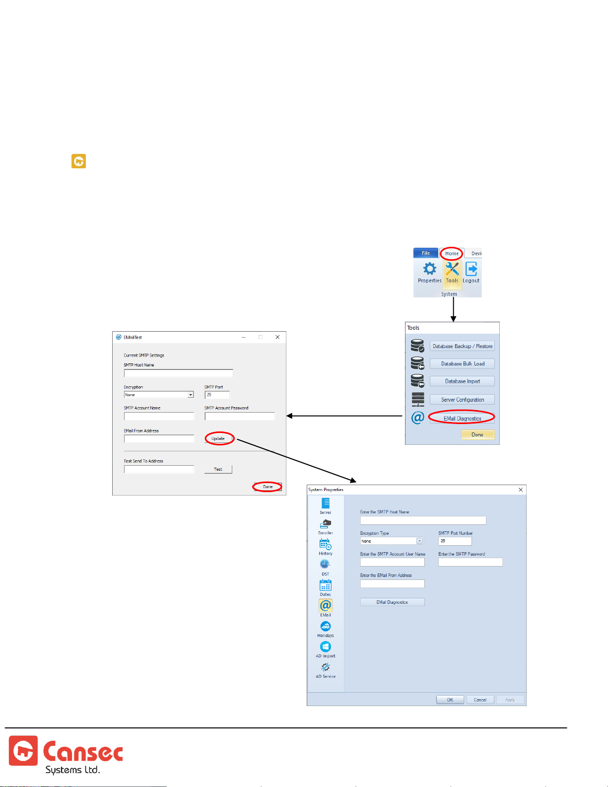
2. Enter the SQL server name along with its instance if necessary.
3. Select appropriate authentication method, build the string connection and click
Test to test the connection.
4. Click Save to save the configuration if the connection is successful.
5. Click Exit when done.
EMAIL DIAGNOSTICS
The Email Diagnostic tool is available in First Access Advanced only. The tool
provides an option to configure and diagnose email setup.
1. Launch Email Diagnostics from the Tools menu.
2. Enter required information below and test sending it.
When successfully sent, click Update to update
settings for the email setup screen.
3. Click Done when finished.
First Access Page 87 of 88
Operator Guide October 2020 • Rev. 2.3
Page 88
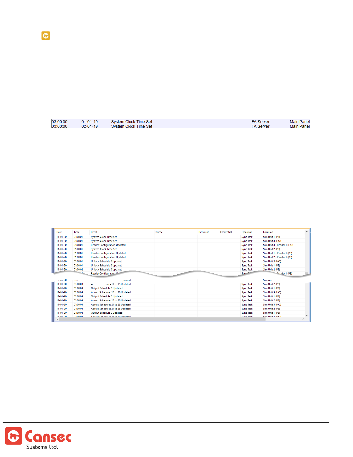
DAILY SYNCHRONIZATION
Clock Synchronization
Every day at 3:00 AM the First Access server software would automatically
synchronize the clock from the computer to all the panels. Since the computer has
the built-in Daylight Saving Time (DST) feature so this would take care of the DST
for all the panels.
Data Synchronization
Every day at 1:00 AM the First Access server software automatically synchronizes
data only to those panels that are flagged as unsynchronized. For example, changes
were made to the database like adding new users but some panels are offline. Those
offline panels will be flagged as unsynchronized and will be synchronized at 1:00
AM. However, if those panels are online before 1:00 AM and the operator does a
manual download to those panels then they are not flagged as unsynchronized.
® First Access is a registered trademark of Cansec Systems Ltd.
® Windows is a registered trademark of Microsoft Corporation in the United States and/or other countries.
First Access Page 88 of 88
Operator Guide October 2020 • Rev. 2.3
 Loading...