

Canovate Can BREEZE Series, Can BREEZE 8 kW, Can BREEZE 14 kW, Can BREEZE 7 kW Operating And Maintenance Instructions Manual
IT’s
far and away
the BEST
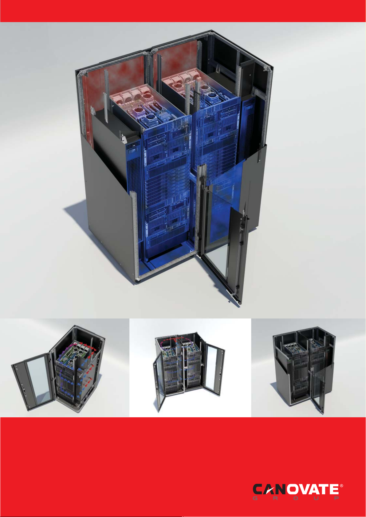
Can BREEZE
Operating and Maintenance of
Cooling Unit Instructions 8-14 kW

1. Canovate Legal Disclaimer
The information presented in this manual is not
warranted by the Canovate to be authoritative, error
free, or complete. This publication is not meant to be
a substitute for a detailed operational and site specifi c
development plan. Therefore, Canovate assumes no
liability for damages, violations of codes, improper
installation, system failures, or any other problems
that could arise based on the use of this Publication.
The information contained in this Publication is
provided as is and has been prepared solely for
the purpose of evaluating data center design and
construction. This Publication has been compiled in
good faith by Canovate. However, no representation
is made or warranty given, either express or implied,
as to the completeness or accuracy of the information
this Publication contains.
IN NO EVENT SHALL CANOVATE, OR ANY PARENT,
AFFILIATE OR SUBSIDIARY COMPANY
OF CANOVATE CORPORATION OR THEIR
RESPECTIVE OFFICERS, DIRECTORS, OR
EMPLOYEES BE LIABLE FOR ANY DIRECT,
INDIRECT, CONSEQUENTIAL, PUNITIVE,
SPECIAL, OR INCIDENTAL DAMAGES (INCLUDING,
WITHOUT LIMITATION, DAMAGES FOR LOSS
OF BUSINESS, CONTRACT, REVENUE, DATA,
INFORMATION, OR BUSINESS INTERRUPTION)
RESULTING FROM, ARISING OUT, OR IN
CONNECTION WITH THE USE OF, OR INABILITY
TO USE THIS PUBLICATION OR THE CONTENT,
EVEN IF CANOVATE CORPORATION HAS BEEN
EXPRESSLY ADVISED OF THE POSSIBILITY
OF SUCH DAMAGES. CANOVATE RESERVES
THE RIGHT TO MAKE CHANGES OR UPDATES
WITH RESPECT TO OR IN THE CONTENT OF THE
PUBLICATION OR THE FORMAT THEREOF AT
ANY TIME WITHOUT NOTICE.
Copyright, intellectual, and all other proprietary rights
in the content (including but not limited to software,
audio, video, text, and photographs) rests with
Canovate or its licensors. All rights in the content not
expressly granted herein are reserved. No rights of
any kind are licensed or assigned or shall otherwise
pass to persons accessing this information.
This Publication shall not be for resale in whole or in
part
2 l Can BREEZE Operating and Maintenance Cooling Unit Instructions 7-14 kW www.canovate.com l info@canovate.com l P. +90 216 484 2222

2. Contents
1. Canovate Legal Disclaimer 2
2. Contents 3
3. General Information 4
3.1 Save these instructions 4
3.2 Intended users 4
3.3 Legal information concerning the
operating instructions
3.4 Copyright 4
3.5 Revision Rev. 4
3.6 Proper use 5
3.7 Precautionary measures 5
3.8 Safety Instructions 5
3.9 Symbols in these operating 5
3.10 instructions 5
3.11 Important safety instructions 6
3.12 Service and technical staff 7
3.13 RoHS compliance 7
4. Transport and handling 8
4.1 Scope of delivery of Front Cooler 8
4.2 Transport 8
4.3 Unpacking 9
6. COMPONENTS 11
6.1
6.2 Components of Fan Unit 11
7. UNITS INSTALLATION 12
7.1 UNIT INSTALLATION 12
7.1.1 FACTORY-SUPPLIED ACCESSORIES 12
7.1.2 INITIAL CHECK 13
8. DRAIN PIPING 13
8.1 GENERAL 13
8.2 DRAIN PIPE CONNECTION 14
9. ELECTRICAL WIRING 16
9.1 ELECTRICAL WIRING CONNECTION
9.2 SETTINGS OF DIP SWITCHES 17
10. MAINTENANCE 19
Components of CAN-BREEZE 11
FOR INDOOR UNIT
4
16
10.1
10.2 CLEAN THE FILTER 20
10.3 RESET OF FILTER INDICATION 20
11. OUTDOOR UNIT 21
11.1 Important Notice 21
12. TRANSPORTATION AND HANDLING 23
13. BEFORE OPERATION 23
14. AUTOMATIC CONTROLS 24
15. BASIC TROUBLESHOOTING 25
16. NAME OF PARTS OUTDOOR UNIT 27
17. UNIT INSTALLATION 29
17.1 OUTDOOR UNIT INSTALLATION 29
17.2 Installation space 30
17.3 Installation place provision 32
18. REFRIGERANT PIPING &
18.1 PIPING MATERIALS 34
18.2 SUSPENSION OF REFRIGERANT
18.3 PIPING CONNECTION FOR
18.4 Refrigerant charge 41
18.5 Caution of the pressure by check joint 41
18.6 Refrigerant Charging Quantity 41
18.7 ELECTRICAL WIRING CONNECTION
18.7.3 Setting of DIP Switches for Outdoor Unit 43
18.7.4 System installation DIP Switch Setting 45
19. TEST RUNNING 47
19.1 TEST RUN PROCEDURE BY REMOTE
19.2 TEST RUN FROM OUTDOOR UNIT
20. Specifi cations 52
21. TROUBLESHOOTING 53
TAKE OUT THE FILTER 19
34
REFRIGERANT CHARGE
35
PIPING
36
OUTDOOR UNIT
42
FOR OUTDOOR UNITS
49
CONTROL SWITCH (PC-ART
EXAMPLE)
50
SIDE
www.canovate.com l info@canovate.com l P. +90 216 484 2222 Can BREEZE Operating and Maintenance Cooling Unit Instructions 8-14 kW l 3

3. General Information
3.1 Save these instructions
This manual contains important instructions that must
be followed during the installation of this
equipment.
3.2 Intended users
This manual is intended for Canovate authorized
personnel. It provides component specifi cations and
instructions for installing and commissioning the
equipment.
3.3 Legal information concerning the
operating instructions
We reserve the right to make changes in content.
Canovate is not responsible for mistakes in this
documentation. Liability for indirect damages which
occur through the delivery or use of this documentation
is excluded to the extent allowable by law.
3.4 Copyright
The distribution and duplication of this document and
the disclosure and use of its contents are prohibited
unless expressly authorised.
Offenders will be liable for damages. All rights created
by a patent grant or registration of a utility model or
design are reserved.
3.5 Revision Rev.
0 of 24 November 2008
4 l Can BREEZE Operating and Maintenance Cooling Unit Instructions 8-14 kW
www.canovate.com l info@canovate.com l P. +90 216 484 2222

3.6 Proper use
The Liquid Cooling Package Inline serves to dissipate
high heat losses and for the effective cooling of
devices built into a server enclosure. The unit is state
of the art and built according to recognised safety
regulations. Nevertheless, improper use can present
a hazard to life and limb of the user or third parties, or
result in possible impairment of the system and other
property. The unit should thus only be used properly
and in technically sound condition. Any malfunctions
which impair safety should be rectifi ed immediately!
Follow the operating instructions! Intended use also
includes following the operating instructions and
fulfi lling the inspection and maintenance conditions.
3.7 Precautionary measures
Inappropriate use may result in danger. Inappropriate
use may include:
- Use of impermissible tools.
- Improper use.
- Improper rectifi cation of malfunctions.
- Use of replacement parts which are not authorised
by Canovate
3.8 Safety Instructions
The Front Coolers produced by Canovate are
developed and produced with due regard to all safety
precautions.
Nevertheless, the unit still causes a number of
unavoidable dangers and risks. The safety instructions
provide you with an overview of these dangers and
the necessary safety precautions.
In the interest of your safety and the safety of others,
please read these safety instructions carefully before
assembly and commissioning of the Front Cooler.
Follow the user information found in these instructions
and on the unit carefully.
3.9 Symbols in these operating
3.10 instructions
Danger!
This warning symbol is used to indicate great
dangers caused by the product which may
result in injury and even death if the indicated
preventative measures are not followed.
Caution!
This warning symbol is used to indicate
procedures which may cause risk of equipment
damage or personal injury.
Note:
This instruction symbol indicates information
concerning individual procedures, explanations,
or tips for simplifi ed approaches.
www.canovate.com l info@canovate.com l P. +90 216 484 2222
Can BREEZE Operating and Maintenance Cooling Unit Instructions 8-14 kW l 5
3.11 Important safety instructions
Danger! Electric shock!
Contact with live electrical parts may be deadly.
Before switching on, ensure that it is not
possible to come into contact with live electrical
parts.
Danger! Injury caused by fan impellors!
Keep persons and objects away from the fan
impellors! Do not remove covers until the power
supply is disconnected and impellors are not
moving! Always use mechanical protection
when working! Shut down the respective fan
as much as possible during maintenance work!
Tie long hair back! Do not wear loose clothing!
Fans start up automatically following power
disruptions!
Danger! Cut wounds, especially through sharp
edges of the fan module and heat exchanger
modules!
Put on protective gloves before beginning
assembly or cleaning work!
Danger! Injury due to falling loads!
Do not stand under suspended loads when
transporting the unit with a hoist trolley, a
forklift, or a crane.
Caution! Risk of malfunction or damage!
Do not modify the unit! Use only original spare
parts!
Caution! Risk of malfunction or damage!
Proper and fl awless unit operation can only be
ensured when it is operated under the intended
ambient conditions. As far as possible, be sure
that the ambient conditions for which the unit is
designed are complied with, e.g. temperature,
humidity, air purity.
Caution! Risk of malfunction or damage!
All media necessary for the control system,
e.g. cooling water, must be available during the
entire operating time.
Caution! Risk of malfunction or damage!
In order to avoid frost damage, the minimum
permissible input water temperature of +6 °C
must not be undercut at any point in the water
cycle!
It is vital that the manufacturers’ consent is
obtained before adding anti-freeze!
6 l Can BREEZE Operating and Maintenance Cooling Unit Instructions 8-14 kW
www.canovate.com l info@canovate.com l P. +90 216 484 2222

Caution! Risk of malfunction or damage!
During storage and transportation below
freezing point, the water cycle should be
drained completely using compressed air!
Caution! Risk of malfunction or damage!
Only set the temperature control setpoint as
low as is strictly necessary, since the danger
of condensation through undercutting the
dew point increases with a falling water inlet
temperature!
Ensure that the enclosure is sealed on all
sides, particularly at the cable
entry (condensation)!
3.12 Service and technical staff
The installation, commissioning, maintenance and
repair of this unit may only be carried out by qualifi ed
mechanical and electro-technical trained personnel.
Only properly instructed personnel may carry out
service on a unit while in operation.
3.13 RoHS compliance
Front Cooler fulfi ls the requirements of EU directive
2002/ 95/EC on the Restriction of Use of Certain
Hazardous Substances in Electrical and Electronic
Equipment (RoHS) of 13 February, 2014.
Note:
Corresponding information concerning the RoHS
directive is provided by our fi rm on the Internet at
www.canovate.com
www.canovate.com l info@canovate.com l P. +90 216 484 2222
Can BREEZE Operating and Maintenance Cooling Unit Instructions 8-14 kW l 7
4. Transport and handling
4.1 Scope of delivery of Front Cooler
The scope of delivery of a Front Cooler includes:
Qty. Parts
Front Cooler, ready for connection
1
1
1
1
1
1
1
4
1 Assembly instructions
Accessories:
Pipe fi tting condensate pump
Condensate hose for condensate pump
Condensate hose emergency overfl ow
Sealing strip
Connection plug
Cable tie and spreading anchor
Jumper for connection plug (strain relief for connection cable)
Eyebolts
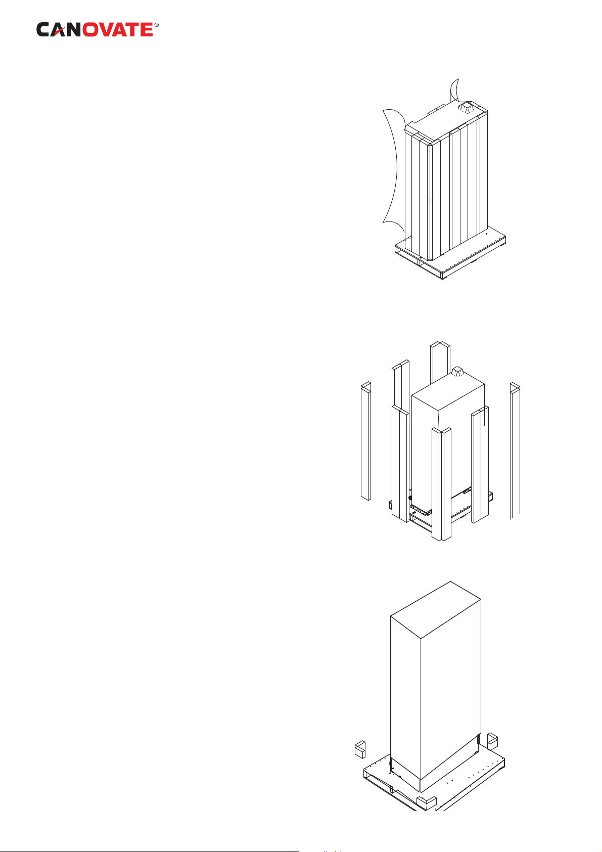
4.2 Transport
The Front Cooler is delivered shrink-wrapped on a
pallet.
Caution!
Because of its height and small base, the Front Cooler
is subject to tipping. Risk of toppling, especially
after the unit is removed from the pallet!
Caution!
Transport of the Front Cooler without a pallet:
- Use only suitable and technically sound lifting
gear and load-bearing devices with suffi cient
load capacity.
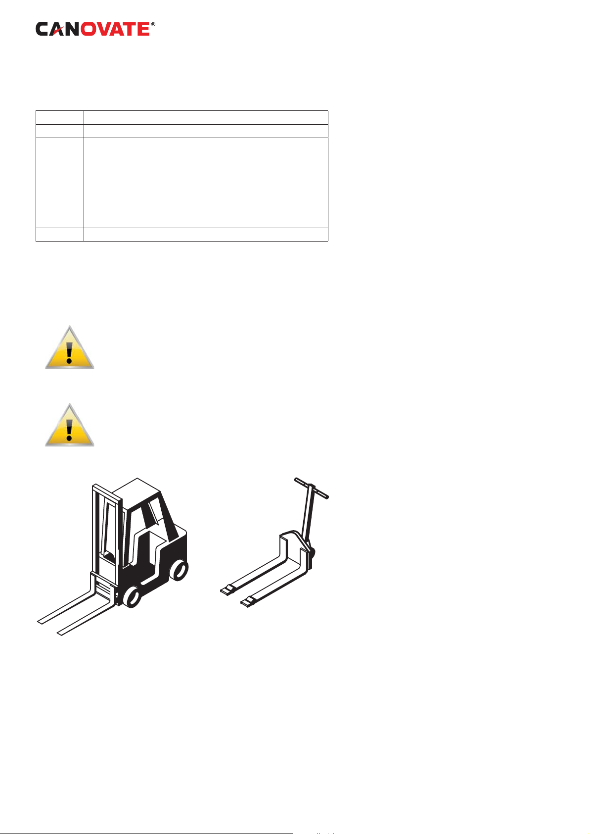
Recommended module handling equipment
Pallet Jack
Forklift
Module Handling
If possible, transport the module using a forklift or
pallet jack.
• If using a forklift or pallet jack, ensure that the fork
tine length is suitable to safely move the packaged
module.
• Canovate recommends keeping the module in the
protective packaging until it has been moved to the
installation site.
• When handling and unpacking the module, exercise
8 l Can BREEZE Operating and Maintenance Cooling Unit Instructions 8-14 kW
www.canovate.com l info@canovate.com l P. +90 216 484 2222

great care to prevent damage.
• Do not lift the module any higher than 6” (152mm)
while moving it. If it must be lifted higher than 6”
(152mm), exercise great care and keep all personnel
who are not helping move the module at least 20’
(5m) away from the module.
• The Front Cooler ships with four outrigger-style
wheels to permit rolling it into position. Canovate
recommends using a forklift or pallet jack to move the
Front Cooler as near as practical to its installation site
before removing it from the shipping pallet.
4.3 Unpacking
Upon arrival of the module and before unpacking,
verify that the labeled equipment matches the bill of
lading. Carefully inspect all items for either visible or
concealed damage. Damage should be immediately
reported to the carrier and a damage claim fi led with a
copy sent to Canovate or to your sales representative.
If you later fi nd any concealed damage, report it to
both the shipping company and your local Canovate
representative.
Check to be sure all required assemblies and parts
have been received.
The Front Cooler is shipped in protective packaging
and secured to a pallet (see Figure 5). Do not remove
these protective items from the Front Cooler before
it is at the installation location. When unpacking and
handling the Front Cooler, exercise extra care to
prevent damage.
Caution
Risk of sudden refrigerant discharge. Can cause loss
of charge and minor injury.
If the optional pre-charged option is chosen, the
Front Cooler module is shipped with a full charge of
R-134a refrigerant under pressure. Do not remove
the pipe caps or plugs before the module is ready for
connection to Front Cooler Piping.
Supply and return fi ttings on the pre-charged Front
Cooler modules are one-shot couplings.
Do not disconnect one-shot couplings after they
have been connected. Disconnection will release
pressurized R-134a refrigerant from the Front Cooler.
Recyclable Packaging
All material used to package this module is recyclable.
Please save for future use or dispose of the material
appropriately.
WARNING : Risk of top-heavy module falling over.
Can cause equipment damage, injury and death.
Read all of the following instructions before attempting
to move, lift, remove packaging from the module, or
www.canovate.com l info@canovate.com l P. +90 216 484 2222
Can BREEZE Operating and Maintenance Cooling Unit Instructions 8-14 kW l 9
preparing module for installation.
Use extreme caution and care when moving and
installing this unit. Use lifting equipment that is rated
for the weight of the unit by an OSHA-certifi ed rating
organization. Personnel should be properly trained
and qualifi ed to move and rig equipment
CAUTION: Risk of sharp edges, splinters and
exposed fasteners. Can cause personal injury.
Only properly trained personnel wearing appropriate
safety headgear, gloves, shoes and glasses should
attempt to move, lift, remove packaging from, or
prepare module for installation
NOTICE :Risk of overhead interference. Can cause
module or structure damage.
The module may be too tall to fi t through a doorway
while on the skid. Measure the module and doorway
heights and refer to the installation plans before
moving the module to verify clearances.
NOTICE: Risk of improper storage. Can cause
module damage.
Keep the module indoors and protected from
dampness, freezing temperatures and contact
damage.
Exterior stretch wrapping
surrounds other protective
shipping features
Planks at the corners and on the sides
protect the Front Cooler during shipping
NOTICE :Risk of damage from forklift. Improper
handling with the forklift can cause exterior and/or
underside damage.
Keep tines of the forklift level and at a height suitable
to fi t below the pallet.
Domestic Packaging
1. Remove the exterior stretch-wrap packaging from
around the module, exposing the protective corner
and side packaging planks.
2. Remove corner and side packaging planks from
the module, exposing the bag over the module.
Remove the bag when ready to install the Front
Cooler.
Remove the Stabilizers at the corners
10 l Can BREEZE Operating and Maintenance Cooling Unit Instructions 8-14 kW
www.canovate.com l info@canovate.com l P. +90 216 484 2222
5.

6. COMPONENTS
6.1 Components of CAN-BREEZE
1 Cabinet Frame
2 Removable Front Glass Door
3 Removable Rear Solid Door
4 Removable Side Panel
5 Fan Unit
6 Rear Panel of Fan’s Filter
7 Heat Exchanger
8 Air Duct
9 Remote Controller
10 Cover of Remote Controller
11 Adjustable Feet
6.2 Components of Fan Unit
1 Fan Motor
2 Fan
3 Fan Case
4 Electrical Control Box
5 Rail of Fan
www.canovate.com l info@canovate.com l P. +90 216 484 2222
Can BREEZE Operating and Maintenance Cooling Unit Instructions 8-14 kW l 11
7. UNITS INSTALLATION
WARNING:
- Check to ensure that the accesso.ries are packed
with the indoor unit.
- Do not install the indoor units outdoors. If installed
outdoors, an electric hazard or electric leakage will
occur.
- Consider the air distribution from each indoor unit to
the space of the room, and select a suitable location
so that uniform air temperature in the room can be
obtained.
- Avoid obstacles which may hamper the air intake or
the air discharge fl ow.
- Pay attention to the following points when the indoor
units are installed in a hospital or other places where
there are electronic waves from medical equipment,
etc.
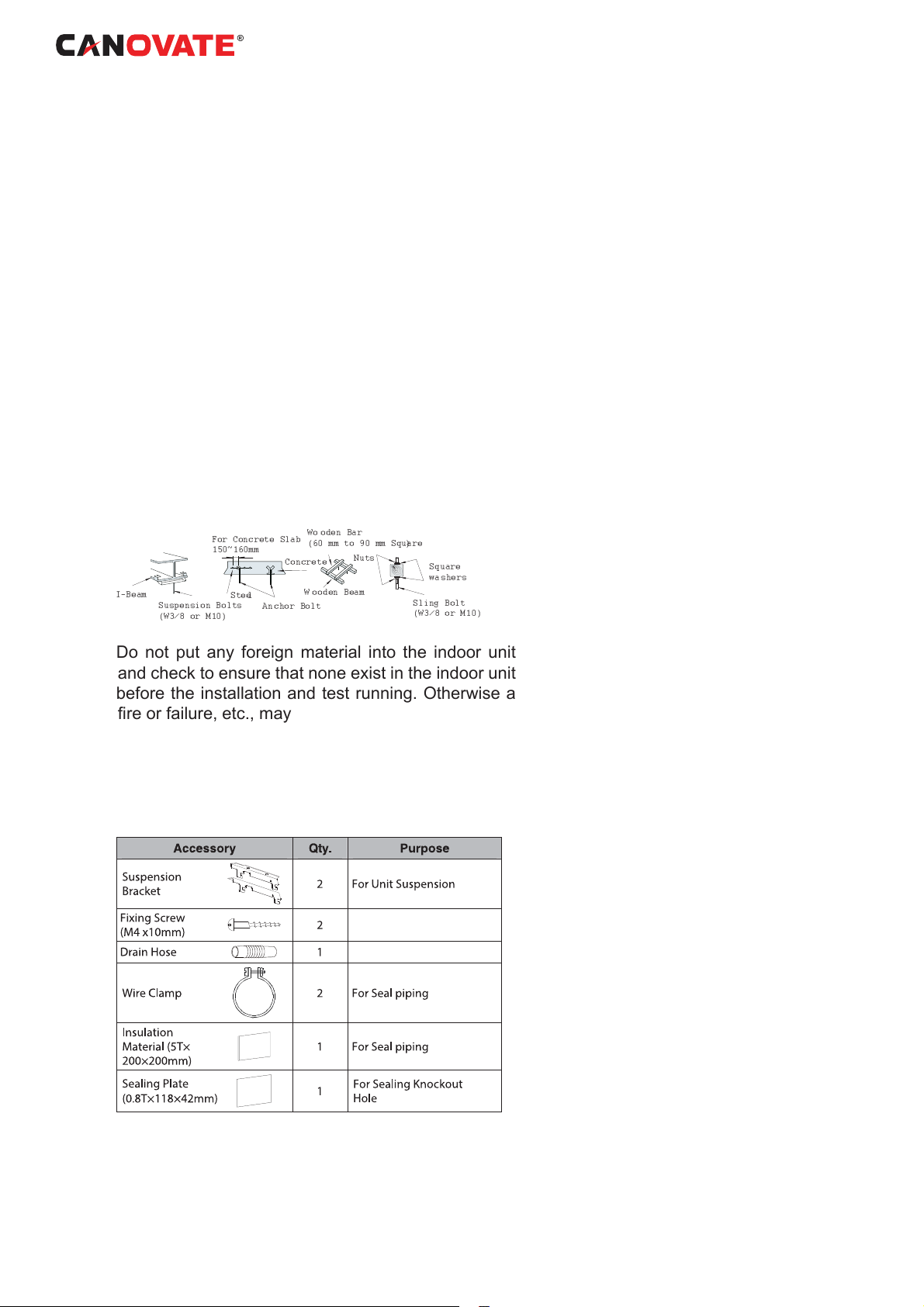
Mount suspension bolts using M10 (W3/8) as size, as
shown below:
For Concrete Slab
150~160mm
I-Beam
Suspension Bolts
(W3/8 or M10)
Steel
Do not put any foreign material into the indoor unit
and check to ensure that none exist in the indoor unit
before the installation and test running. Otherwise a
fi re or failure, etc., may occur.
Wo oden Bar
(60 mm to 90 mm Square)
Concrete
W ooden Beam
Anchor Bolt
Nuts
Square
washers
Sling Bolt
(W3/8 or M10)
7.1 UNIT INSTALLATION
7.1.1 F A C T O R Y -SUPPLIED
ACCESSORIES
12 l Can BREEZE Operating and Maintenance Cooling Unit Instructions 8-14 kW
www.canovate.com l info@canovate.com l P. +90 216 484 2222
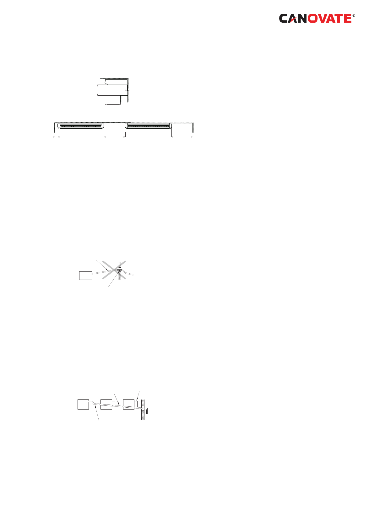
7.1.2 INITIAL CHECK
Indoor unit with proper clearance around it for
operation and maintenance working space, as
shown below
Min. 500
Min.400
Min. 40
Check down slope pitch of drain piping is following
the specifi cation indicate in chapter ‘Drain Piping’
8. DRAIN PIPING
8.1 GENERAL
CAUTION:
- Do not create an upper-slope or rise for the drain
piping, since drain water will fl ow back to the unit
and
leakage to the room will occur when the unit
operation is stopped.
Incorrect: Upward Slope
Min. 8
(mm)
Min. 300Min. 300
INCORRECT
Incorrect: Rising Part
Do not connect the drain pipe with sanitary or
sewage
piping or any other drainage piping.
- When the common drain piping is connected
with other indoor units, the connected position of
each indoor unit must be higher than the common
piping.
The pipe size of the common drain pipe must
be large enough according to the unit size and
number of unit.
Drain Piping connection
CORRECT
1/25~1/100 Down Slope
Common Drain Piping
Drain piping will require insulating if the drain is
installed in a location where condensation forming
on
the outside of drain pipe may drop and cause
damage. The insulation for the drain pipe must
be selected to insure vapor sealing and prevent
condensation forming.
www.canovate.com l info@canovate.com l P. +90 216 484 2222
Can BREEZE Operating and Maintenance Cooling Unit Instructions 8-14 kW l 13

Drain trap should be installed next to indoor unit. This
trap must be designed to good practice and be
checked with water (charged) and tested for correct
fl ow. Do not tie or clamp the drain pipe and refrigerant
pipe together.
NOTE:
Install drainage in accordance with national and local
codes.
After performing drain piping work and electrical
wiring, check to ensure that water fl ows smoothly as
in the following procedure:
Checking Unit without Drain-up Mechanism
- Pour approximately 1.8 liters of water into the drain
pan.
- Check to ensure that the water fl ows smoothly or
whether no water leakage occurs. When water cannot
be found at the end of the drain piping, pour another
approximately 1.8 liters of water into the drain pan.
NOTE:
Pay attention to the thickness of the insulation when
the left side piping is performed. If it is too thick, piping
can not be installed in the unit.
8.2 DRAIN PIPE CONNECTION
The standard direction of drain piping connection
is right side as viewed from the discharge grilles.
However, it can be performed from the left side
connection is required due to the building construction.
For Right Side Connection
1. Insert the hose into the wire clamp.
2. Push the drain hose onto the drain boss until the
hose reaches the end of the drain pan.
3. Tighten the screw for the wire clamp in order to
hold the hose around the drain connection without
any leakage of drain water as shown bellow.
4. Insulate the drain hose around the wire clamp to
prevent any condensation as shown.
Drain Hose
Wire Clamp A
Wire Clamp b
14 l Can BREEZE Operating and Maintenance Cooling Unit Instructions 8-14 kW
Drain Pipe
Insulation
Drain Boss
www.canovate.com l info@canovate.com l P. +90 216 484 2222

For Left Side Connection
Fan Runner
Drain Boss
Fan Motor
Rear Side
Insulation Plug
Drain Plug
Fastener Band
Drain Plug
Remove the drain plug of the left-side drain boss as
indicated in the following procedure.
1. Cut the fastener.
2. Remove the insulation material.
3. Remove the drain plug.
4. Insert the drain plug into the right-side and drain
boss using a driver as shown below.
Driver
Drain Plug
Drain Connection
Unit
Side
5. After inserting the drain plug into the right-side drain
boss, seal the jointed part by using a water-proof
chloride type sealing material and secure it with a
fastener.
Seal Material
Plug
6. Wrap the insulation material around the drain
connection.
7. Connect the drain hose to the left side drain
connection using the same procedure as for the right
side drain connection.
Connecting a Drain Piping
1. Prepare a polyvinyl chloride (PVC) tube with an
outer diameter of 26mm. (VP20)
2. Pay attention to the position of the drain pipe. Keep
the down-slope, 1/25 to 1/100. Do not create an upper
slope or rise for the drain piping.
3. Seal the connecting part of the drain pipe by using
the water-proof chloride type sealing material.
4. Wrap the insulation material around the connecting
part perfectly.
5. Fasten the drain pipe to the connecting part using
the factory-supplied clamp.
www.canovate.com l info@canovate.com l P. +90 216 484 2222
Can BREEZE Operating and Maintenance Cooling Unit Instructions 8-14 kW l 15
Drain Hose
(
)
Insulation
eld supplied
Secure
Downward
Slope
Insulation
Clamp
6. Do not connect the drain pipe with sanitary sewage
or any other drainage pipe.
7. When installing the pipe, do not tie the drain pipe
and refrigerant pipe together. Tie the drain pipe as
shown below
Band
Rear Side piping
Band
8. After completing the drain pipe work, pour water
into the drain pan and check to ensure that water
fl ows smoothly
9. ELECTRICAL WIRING
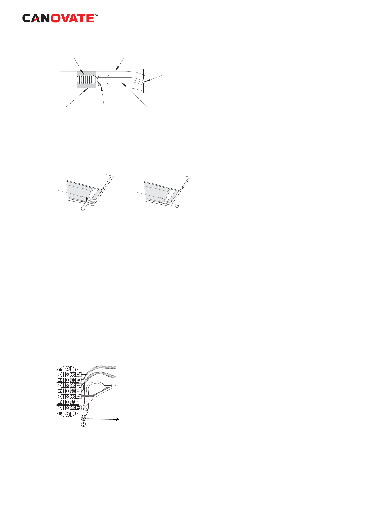
9.1 ELECTRICAL WIRING CONNECTION
FOR INDOOR UNIT
CAUTION:
Use twisted shielded pair cable or shield pair cable
for transmission wires between the indoor and the
outdoor units, and connect the shielded part to the
earth screw in the electrical box of the indoor unit as
shown below.
Single phase connection
Remote Control (PC-ART)
Transmission Wires
Power supply wires
(Single phase)
Earth Screw
Rear Side piping
16 l Can BREEZE Operating and Maintenance Cooling Unit Instructions 8-14 kW
www.canovate.com l info@canovate.com l P. +90 216 484 2222
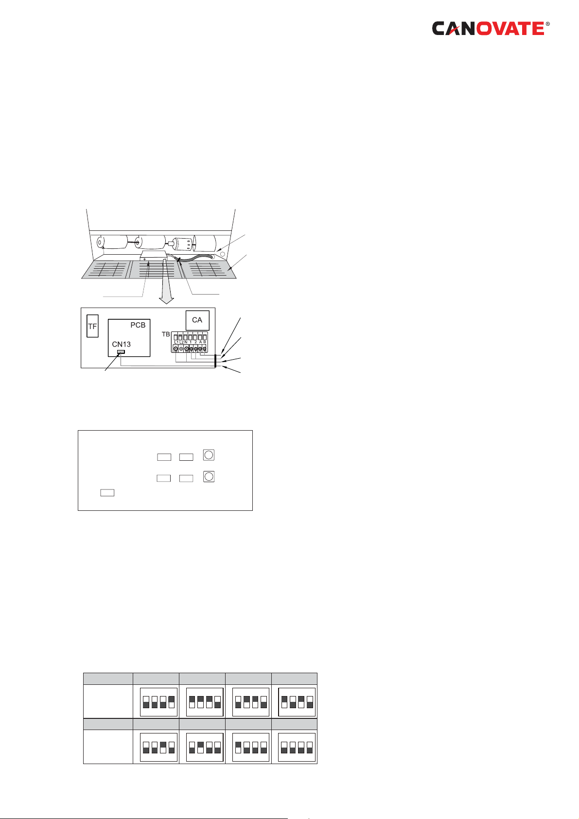
The electrical wiring connection for the indoor unit is
shown below.
1. Connect the cable of the remote control switch to
the terminals A and B in electrical box through the
connecting hole in the cabinet, as shown below.
2. Connect the power supply and ground wires to the
terminals in the electrical box.
3. Connect the wires between the indoor unit and the
outdoor unit to the terminals 1 and 2 in the electrical
box, as shown below:
Knockout hole
for wirings
Grille
Electrical Box
Connector
Cord clamp
RCS (Optional)
Transmission wires
Power wires
RCS (Optional)
9.2 SETTINGS OF DIP SWITCHES
Quantity and Position of Dip Switches
Dips switches position is the following:
RSW2
DSW5
DSW4
DSW3
DSW6
RSW1
DSW7
CAUTION:
Before setting dips switches, fi rstly turn off power
source and set the position of the dips switches. If the
switches are set without turning off the power source,
the contents of the setting are invalid.
DSW3: Capacity Code Setting
No setting is required, due to setting before shipment.
This dip switch is utilized for setting the capacity code
which corresponds to the Horse Power of the indoor
unit.
HP 1.8 2.0 2.3 2.5
Setting
Position
ON
1 2 3 4
3.0 4.0 5.0 6.0
Setting
Position
www.canovate.com l info@canovate.com l P. +90 216 484 2222
ON
1 2 3 4
ON
1 2 3 4
ON
1 2 3 4
ON
1 2 3 4
ON
1 2 3 4
ON
1 2 3 4
ON
1 2 3 4
Can BREEZE Operating and Maintenance Cooling Unit Instructions 8-14 kW l 17

DSW6 and RSW1: Unit No. Setting
The below fi gure indicates the position before
shipment.
Indication
Use athead driver
DSW6 RSW1
ON
1 2 3 4 5 6
Here is set DSW6 and RSW1 before shipment up to 63
can be set.
Ex. Setting nº16
ON
1 2 3 4 5 6
Nº 1 PIN is on
RSW1
Fix to 6
DSW5 and RSW2: Refrigerant Cycle No. Setting
Setting is required. Setting position before shipment
in
DSW5 RSW2
ON
1 2 3 4 5 6
Here is set DSW5 and RSW2 before shipment up to 63
can be set.
Ex. Setting 5
system
RSW2
ON
1 2 3 4 5 6
All pins are OFF
Fix to 5
DSW4: Unit Model Code Setting
No setting is required. This switch is utilized for setting
the model code which corresponds to the indoor unit
type.
Indoor Unit Model DSW4 Setting
RPC
18 l Can BREEZE Operating and Maintenance Cooling Unit Instructions 8-14 kW
ON
1 2 3 4
www.canovate.com l info@canovate.com l P. +90 216 484 2222

DSW7: Fuse Recover
In case of applying high voltage to the terminal
1,2 of TB1, the fuse on the PCB1(M) is cut. In
such a case, rstly correct the wiring to TB1 and
then turn ON #1 (as showing beside)
DSW7: Remote Control Selection
No setting is required. Setting position before
shipment is all OFF (PC-ART) Remote Control
Switch Selected).
NOTE:
- The mark “■“ indicates position of dips switches.
Figures show setting before shipment or after
selection.
10. MAINTENANCE
Do not operate the system without the air fi lter to
protect the indoor unit heat exchanger against being
clogged. Turn OFF the main power switch before
taking out the fi lter. (The previous operation mode
may appear.)
The indication, “FILTER” is shown on the display
of the remote control switch. Take out the air fi lter
according to the indicated steps for each unit.
ON
ON
1 2
1 2
10.1 TAKE OUT THE FILTER
Ceiling Type
1. Side the knobs.
Knob
2. Open the air inlet grille.
3. Take out the air fi lter from the air inlet grille.
www.canovate.com l info@canovate.com l P. +90 216 484 2222
Can BREEZE Operating and Maintenance Cooling Unit Instructions 8-14 kW l 19

10.2 CLEAN THE FILTER
Clean the air fi lter according to the following steps:
1. Use a vacuum cleaner or let water fl ow onto the air
fi lter for removing the dirt from the air fi lter.
CAUTION:
Do not use hot water higher than approximately 40ªC
2. Dry the air fi lter in the shade after shaking off
moisture.
3. Do not use cleaner or other chemicals
10.3 RESET OF FILTER INDICATION
After cleaning the air fi lter, press the “RESET” button.
The FILTER indication will disappear and the next
fi lter cleaning time is set.
20 l Can BREEZE Operating and Maintenance Cooling Unit Instructions 8-14 kW
www.canovate.com l info@canovate.com l P. +90 216 484 2222
11. OUTDOOR UNIT
11.1 Important Notice
• No part of this manual may be reproduced without
written permission.
• If you have any questions, contact your service
contractor of Canovate.
• This manual gives a common description and
information for this air conditioner which you operate
as well as for other models.
• Check and make sure that the explanations of each
part of this manual correspond to your air conditioner
model.
• Refer to the models codifi cation to confi rm the main
characteristics of your system.
• Signal words (DANGER, WARNING and CAUTION)
are used to identify levels of hazard seriousness.
Defi nitions for identifying hazard levels are provided
below with their respective signal words.
• It is assumed that this unit will be operated and
serviced by English speaking people. If this is not the
case, the customer should add safety, caution and
operating signs in the native language of the personal.
• This air conditioner has been designed for the
following temperature. Operate the air conditioner
within this range:
Temperature
Maximum Minimum
Cooling
Mode
Heating
Mode
DB: Dry Bulb Temperature
WB: Wet Bulb Temperature
Indoor 32°C DB/23°C WB
Outdoor 46 ºC DB
Indoor 27 °C DB
Outdoor 15 °C WB
21°C DB/15°C WB
-5 °C DB
15 °C DB
-20 °C WB
These operations modes are controlled by the remote
control switch.
• This manual should be considered as a permanent
part of the air conditioner. This manual gives a
common description and information for this air
conditioner which you operate as well as for other
models.
DANGER
Pressure Vessel and Safety Device: This air
conditioner is equipped with a high pressure vessel
under PED (Pressure Equipment Directive). The
pressure vessel has been designed and tested
before shipment according to PED. Also, in order to
prevent the system from an abnormal pressure, a high
pressure switch, which needs no fi eld adjustment, is
www.canovate.com l info@canovate.com l P. +90 216 484 2222
Can BREEZE Operating and Maintenance Cooling Unit Instructions 8-14 kW l 21

utilized in the refrigeration system.
Therefore, this air conditioner is protected from
abnormal pressures. However, if abnormally high
pressure is applied to the refrigeration cycle including
the high pressure vessel(s), it will result in serious
injury or death due to explosion of the pressure
vessel.
Do not apply a pressure higher than the following
pressure to the system, by modifying or changing the
high pressure switch.
CAUTION
This unit is designed for commercial and light industrial
application.
If installed in house hold appliance, it could cause
electromagnetic interference.
Start-up and Operation: Check to ensure that all the
stop valves are fully opened and no obstacle exists
at the inlet/outlet sides before start-up and during the
operation.
Maintenance: Periodically check the high pressure
side pressure.
If the pressure is higher than the maximum allowable
pressure, stop the system and clean the heat
exchanger or remove the cause.
Maximum Allowable Pressure and High Pressure
Cut-out Value:
Outdoor Unit Model Refrigerant
8 kW
14 kW R410A 4.15 4.00 ~ 4.10
R410A
Maximum Allowable
Pressure (MPa)
4.15
High Pressure Switch
Cut-out Value (MPa)
4.00 ~ 4.10
NOTE
The label for the vessel under PED are attached
on the high pressure vessel. The pressure vessel
capacity and vessel category are indicated on the
vessel.
Location of High Pressure Switch
Compressor
NOTE
The high pressure switch is indicated on the electrical
wiring diagram in the outdoor unit as PSH connected
to printed circuit board (PCB1) in the outdoor unit
22 l Can BREEZE Operating and Maintenance Cooling Unit Instructions 8-14 kW
www.canovate.com l info@canovate.com l P. +90 216 484 2222

Structure of High Pressure Switch
Contact Point Pressure Detected
Connected to the electrical wire
DANGER
Do not change the high-pressure switch locally or
change the high pressure cut-out set value locally. If
changed, it will cause serious injury or death due to
explosion. Do not attempt to turn service valve rod
beyond its stop.
12. TRANSPORTATION AND
HANDLING
When hanging the unit, ensure a balance of the unit,
check safety and lift it up smoothly
Do not remove any packing materials.
Hang the unit under packing condition with two ropes.
For safety reasons ensure that the outdoor unit is
lifted smoothly and does not lean
Model
8-14 kW
Gross
Weight (kg)
90
13. BEFORE OPERATION
CAUTION
Supply electrical power to the system for approximately
12 hours before start-up or a long shutdown. Do not
start the system immediately after power supply,
it may cause a compressor failure because the
compressor is not heated well.
When the system is started after a shutdown longer
that approximately 3 months, it is recommended to
check the system by your service contractor.
> 60º
0.7 -1.0 m
Turn OFF the main switch when the system is to be
stopped for a long period of time: If the main switch
www.canovate.com l info@canovate.com l P. +90 216 484 2222
Can BREEZE Operating and Maintenance Cooling Unit Instructions 8-14 kW l 23

is not turned OFF
the oil heater is always energised during compressor
stopping.
Make sure that the outdoor unit is not covered with
snow or ice.
If covered, remove it by using hot water (approximately
50°C). If the water temperature is higher that 50 °C, it
will cause damage to plastic parts.
, electricity will be used, because
14. AUT
The system is equipped with the following functions.
Three minute guard
The compressor remains of
once it has stopped. If the system is started within
approximately 3 minutes after it has stopped, the
RUN indicator is activated. However, the cooling
operation or the heating operation remains off and
does not start until after 3 minutes has elapsed.
Operation may stop for 6 minutes maximum to protect
compressor.
Frost prevention during cooling operation
When the system is operated in a low temperature
room, the cooling operation may be changed to fan
operation for a while to avoid frost formation on the
indoor heat exchanger.
Automatic restart after power failure
If the power supply is interrupted for short periods of
time (up to 2 seconds) the Remote Control switch will
retain the settings and the unit will restart when the
power is restored. If Automatic Restart is required after
periods of lost power supply in excess of 2 seconds
please contact your distributor (optional function).
OMATIC CONTROLS
f for at least 3 minutes
Slow air control during heating operation
Can be setting than when the compressor is stopped
while the thermostat is OFF, or the system is
performing the automatic defrosting operation, the
fan speed is set at the slow position.
Automatic defrosting cycle
When the heating operation is stopped by pressing
RUN/STOP switch, frosting on the outdoor unit
is checked and the defrosting operation may be
performed for the maximum of 10 minutes.
Prevention of overload operation
When the outdoor temperature is too high during
heating operation, heating operation is stopped
due to activation of the outdoor thermistor until the
temperature becomes low.
Hot start during heating operation
To prevent cold air discharge, the fan speed is
controlled from the slow position to the set position
according to the discharge air temperature. At this
time the lover is fi xed horizontally.
24 l Can BREEZE Operating and Maintenance Cooling Unit Instructions 8-14 kW www.canovate.com l info@canovate.com l P. +90 216 484 2222

15. BASIC TROUBLESHOOTING
CAUTION
When water leakage from the indoor unit occurs, stop
the operation and contact your contractor
When you smell or white smoke occurs from the unit,
stop the system and contact your contractor.
This is not abnormal
• Sound from deforming Part
During system starting or stopping, and abrading
sound might be heard. However, this is due to thermal
deformation of plastic parts. It is not abnormal.
• Refrigerant Flow Sound
While the system is being started or stopping, sound
from the refrigerant fl ow may be heard.
• Smells from Indoor Unit
Smell adheres on indoor unit after a long period of
time. Clean the air fi lter and panels or make a good
ventilation.
• Steam from Outdoor Heat Exchanger
During defrosting operation, ice on the outdoor heat
exchanger is melted, resulting in making steam.
• Dew on Air Panel
When the cooling operation continues for a long
period of time under high humidity conditions (higher
than 27°C DB/80% R.H.), dew can form on the air
panel.
• Dew on Cabinet
When the cooling operation continues for a long
period of timer (higher than 27°C DB/80% R.H.), dew
can form on the cabinet.
• Sound for the indoor unit heat exchanger
During the cooling operation, a sound may be heard
from the indoor unit heat exchanger due to water
freezing or melting.
No operation
Check whether the SET TEMPERATURE is set at the
correct temperature.
Not cooling well or heating well
-- Check for obstruction of air fl ow of the outside or
inside units.
-- Check if too much heat source exists in the room.
-- Check if the air fi lter is clogged with dust.
-- Check to see if the doors or windows are opened
or not.
-- Check if the temperature condition is not within the
operating range.
Abnormal swing louver’s position
Check if the four louver’s position at the air outlet are
in same
www.canovate.com l info@canovate.com l P. +90 216 484 2222
Can BREEZE Operating and Maintenance Cooling Unit Instructions 8-14 kW l 25

position.
If trouble still remains...
If the trouble still remains even after checking the
above items, contact your service contractor and
inform the following data:
-- Unit Model Name
-- Content of Trouble
-- Alarm Code no. on Liquid Crystal Display
NOTE
Except for a long period of shutdown, keep the main
switch ON, since the oil heater is energised when the
compressor is stopped.
26 l Can BREEZE Operating and Maintenance Cooling Unit Instructions 8-14 kW
www.canovate.com l info@canovate.com l P. +90 216 484 2222

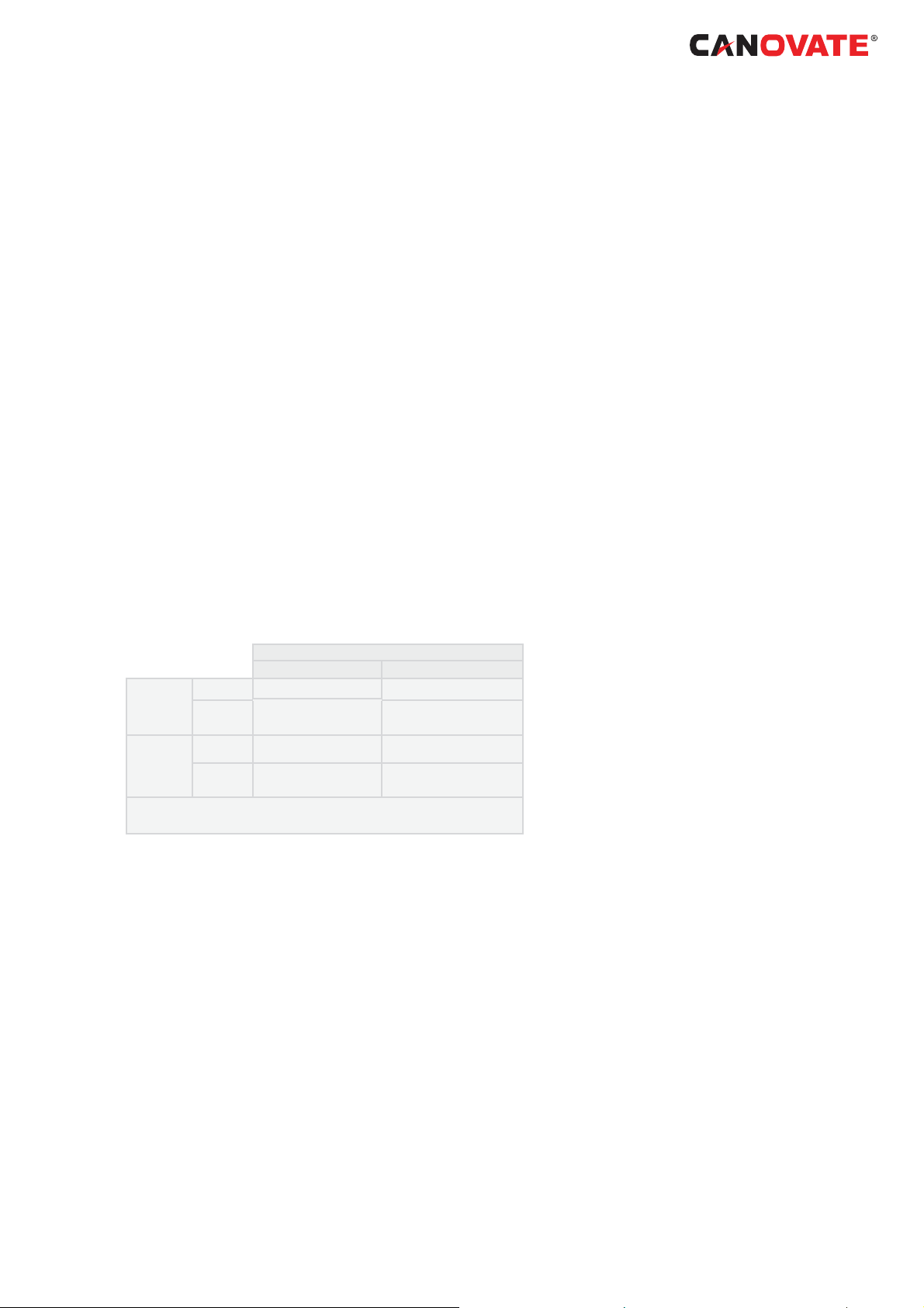
16. NAME OF PARTS OUTDOOR UNIT
No. Part Name
1 Compressor
2 Accumulator
3 Heat exchanger
4 Propeller fan
5 Fan motor
6 Strainer
7 Distributor
8 Reversing valve
9 Micro-computer control expansion
valve
10 Solenoid valve for hot gas
11 Stop valve for gas line
12 Stop valve for liquid line
13 Check Joint
14 Electrical box
15 High pressure switch for protection
17 Pressure switch for control
18 Silencer
19 Crankcase heater
20 Vibration absorbing rubber (3pcs.)
21 Air outlet
22 Air inlet
www.canovate.com l info@canovate.com l P. +90 216 484 2222
Can BREEZE Operating and Maintenance Cooling Unit Instructions 8-14 kW l 27
C
F
D
F
B
A
E
Mark Part name
A Gas line refrigerant piping connection
B Liquid line refrigerant piping connection
C Outdoor unit
D Ambient thermistor
E Discharge gas thermistor
F Pipe thermistor
No Part name
1 Compressor
2 Heat exchanger
3 Accumulator
4 Micro-Computer control expansion valve
5 Reversing valve
6 Solenoid valve for gas bypass
7 Strainer
8 Distributor
9 Check joint
10 High pressure switch for protection
11 Pressure switch for control
12 Stop valve for gas line
13 Stop valve for liquid line
14 Silencer
or cooling for heating
28 l Can BREEZE Operating and Maintenance Cooling Unit Instructions 8-14 kW
Connection by
Connection by
welding
www.canovate.com l info@canovate.com l P. +90 216 484 2222
R410A 4.15 MPa
Gas refrigerant
Leakage test
pressure

17. UNIT INSTALLATION
17.1 OUTDOOR UNIT INSTALLATION
CAUTION
Transport the products as close to the installation
location as practical before unpacking.
Do not put any material on the products.
Apply four lifting wires on to the outdoor, when lifting
it by crane
CAUTION
• Install the outdoor unit with suffi cient clearance
around it for operation and maintenance as shown in
the next fi gures. Install the outdoor unit where good
ventilation is available
• Do not install the outdoor unit where is a high
level of oil mist, salty air or sulphurous atmosphere.
• Install the outdoor unit as far as practical (being
at least 3 meters) from electromagnetic wave radiator
(such as medical equipment).
• For cleaning, use noninfl ammable and
nontoxic cleaning liq- uid. Use of infl ammable agent
may cause explosion or fi re.
• Work with suffi cient ventilation, for working in
an enclosed space may cause oxygen defi ciency.
Toxic gas may be pro- duced when cleaning agent is
heated to high temperature by, e.g., being exposed to
fi re.
• Cleaning liquid shall be collected after cleaning.
• Pay attention not to clamp cables when
attaching the service cover to avoid electric shock or
fi re.
C A U T I O N
Keep clearance between the units of more than
100mm, and avoid obstacles that may hamper air
intake, when installing more than one units together.
Install the outdoor unit in the shade or not exposed
to direct sun- shine or direct radiation from high
temperature heat source.
Do not install the Outdoor Unit in a space where a
seasonal wind directly blows to the Outdoor fan.
Check to ensure that the foundation is fl at, level and
suffi ciently strong.
Install the unit in a restricted area not accessible by
the general public Aluminium fi ns have very sharp
edges. Pay attention to the fi ns to avoid injury
www.canovate.com l info@canovate.com l P. +90 216 484 2222
Can BREEZE Operating and Maintenance Cooling Unit Instructions 8-14 kW l 29

17.2 Installation space
(Unit: mm)
Single Installation Multiple Installation (Two units or more)
Blocked in Inlet Side
Upper Side Open
200 or more of the back space is acceptable when the right and
left sides are open.
Allow 100 mm of space between units. Leave open both right and left sides.
30 l Can BREEZE Operating and Maintenance Cooling Unit Instructions 8-14 kW
www.canovate.com l info@canovate.com l P. +90 216 484 2222

Blocked in Inlet Side
Be sure to use the fan direction guide. Leave open both right and
left sides.
Upper Side Blocked
Single Installation Multiple Installation (Two units or more)
Be sure to use the fan direction guide. Allow 100 mm of space between units.
Leave open both right and left sides.
100 mm or more of the side space is acceptable on the service
cover side.
Leave open both right and left sides.
The length A is as shown in the following table:
LA
0 < L+ 600 or greater
+/+ 1400 or greater
Single Installation Multiple Installation (Two units or more)
Allow 100 mm of space between units. Leave open both right and left sides..
Be sure to use the fan direction guide. Allow 100 mm of space between units.
Leave open both right and left sides.
No more than 2 units for multiple installation.
When L!+XVHDEDVHIRURXWGRRUXQLWWRPDNHL+
Close the base not to allow the outlet air bypassed.
Outlet Side Blocked
Upper Side Open
Allow 100 mm of space between units. Both right and left sides shall be open.
Be sure to use the fan direction guide. Leave open both right and
left sides.
The length A is as shown in the following table:
LA
0 < L+ 600 or greater
+/+ 1400 or greater
Be sure to use the fan direction guide. Allow 100 mm of space between units.
Leave open both right and left sides.
No more than 2 units for multiple installation.
When L!+XVHDEDVHIRURXWGRRUXQLWWRPDNHL+
Close the base not to allow the outlet air bypassed.
www.canovate.com l info@canovate.com l P. +90 216 484 2222
Can BREEZE Operating and Maintenance Cooling Unit Instructions 8-14 kW l 31

17.3
Installation place provision
Concrete Foundation
1
Foundation could be on fl at and is
recommended be 100-300 mm higher than ground
level.
2 Install a drainage around foundation for smooth
drain
3 When installing the outdoor unit fi x the unit by
anchor bolts of M10.
4 When installing the unit on a roof or a veranda,
drain water sometimes turns to ice on a cold morning.
Therefore, avoid draining in an area that people often
use because it is slippery.
Space for downward piping space
*
Nº
Outdoor Unit
1
2
Mortar Hole (Ø100xDepth 150)
3
Anchor Bolt M10 (Ø12.5 Hole)
4
Drainage (Wide 100xDepth 150)
5
Drainage
6
V
ibration-proof rubber
7
Description
N O T E
When the mark * dimension is secured, piping work
from bottom side is easy without interference of
foundation.
5
The whole of the base of the outdoor unit
should be installed on a foundation. When using
vibration-proof mat, it should also be positioned the
same way. When installing the outdoor unit on a fi eld
supplied frame, use metal plates to adjust the frame
width for stable installation as shown in below fi gure.
32 l Can BREEZE Operating and Maintenance Cooling Unit Instructions 8-14 kW www.canovate.com l info@canovate.com l P. +90 216 484 2222

Outdoor unit is
unstable
Frame
Outdoor unit is
stable
Frame
INCORRECT
70 mm
Base width of outdoor unit
60mm
Frame with (Field supplied)
CORRECT
70 mm
Base width of outdoor unit
100mm or more
Metal plate
Recommended Metal Plate Size
- (Field-Supplied) Material: Hot-Rolled Mild
Steel
- Plate (SPHC) Plate Thickness: 4.5 T
www.canovate.com l info@canovate.com l P. +90 216 484 2222
Can BREEZE Operating and Maintenance Cooling Unit Instructions 8-14 kW l 33

Fix Unit to the wall
1. -
2. Ensure the foundation so that avoid
the deforming and noise.
3. In case of prevention from vibration
transfer to the building, use rubber
Mat.
Suspended unit
1. Suspend the unit as the drawing
indicates.
2. Ensure that wall can resist the Outcation label plate.
3. It is recommended to select each foot
support to bear the full weight of
the unit (in order to consider stress
fatigue applied when unit is working
too).
Installing location where the unit will be exposed to strong wind.
-
(*) Field supplied
Rubber Material
(Field Supplied)
Wall bracket (*)
Anchor Bolts (*)
Mark Dimension
Model
A (mm) 529
7-14 kW
CAUTION
Pay attention to the following for installation:
Installation shall ensure that outdoor
unit will not incline, vibrate, make noise
or fall down by a blast of wind or in an
earthquake. Calculate quake-resistance
strength to ensure that installation is
strong enough against falling. Fix the unit
in a location without walls or windbreak
and likely exposed to a blast of wind.
to the front and back.
Follow the instructions below to install
on the rooftop or a location without surrounding buildings, where strong wind is
expected against the product.
1. Choose a location where the outlet or
inlet side of the product will not be
exposed to strong wind.
2. When the outlet is exposed to strong
wind:
Direct strong wind may cause lack
operation.
18. REFRIGERANT PIPING &
REFRIGERANT CHARGE
18.1 PIPING MATERIALS
1 Prepare locally-supplied copper pipes.
2 Select the piping size with the correct thickness
and correct material which can have suffi cient
pressure strength.
3 Select clean copper pipes. Make sure there is
no dust and moisture inside. Blow the inside of the
pipes with oxygen free nitrogen to remove any dust
and foreign materials before con- necting pipes.
CAUTION
Excessive strong wind against the outdoor unit
outlet may cause inverse rotation and damage
the fan and motor.
N O T E
A system with no moisture or oil contamination will
give maximum performance and lifecycle compared
34 l Can BREEZE Operating and Maintenance Cooling Unit Instructions 8-14 kW
www.canovate.com l info@canovate.com l P. +90 216 484 2222

to that of a poorly prepared system. Take particular
care to ensure all copper piping is clean and dry
internally.
There is no refrigerant in the cycle of the indoor unit.
C A U T I O N
Cap the end of the pipe when pipe is to be inserted
through a hole
Do not put pipes on the ground directly without a cap
or vinyl tape at the end of the pipe
If piping installation is not completed until next day
or over a long- er period of time, braze off the ends
of the piping and charge with oxygen free nitrogen
through a Schrader valve type access fi tting to
prevent moisture and particle contamination.
Do not use insulation material that contains NH3
because it can damage cooper pipe material and can
be a source of future leak- age.
Completely insulate both refrigerant gas piping and
liquid piping between the indoor unit(s) and the
outdoor unit.
If not insulated, dew will ocur on the piping surface
18.2 SUSPENSION OF REFRIGERANT
PIPING
Suspend the refrigerant piping at certain points and
prevent the refrigerant piping from touching the weak
part of the building such as wall, ceiling, etc…
(If touched, abnormal sound may occur due to the
vibration of the piping. Pay special attention in case
of short piping length).
1~15m
Fire-Proof
Section Treatment
Indoor unit
Do not fi x the refrigerant piping directly with the
metal fi ttings (The refrigerant piping may expand and
contract).
Some examples for suspension method are shown
below.
www.canovate.com l info@canovate.com l P. +90 216 484 2222
Can BREEZE Operating and Maintenance Cooling Unit Instructions 8-14 kW l 35

For Suspending
Heavies
For piping along
the wall
For instant
installation work
18.3 PIPING CONNECTION FOR
OUTDOOR UNIT
1 The pipes can be connected from 4 directions.
Make holes in the piping cover or cabinet for taking
out pipes. Take the pip- ing cover away from the unit,
and make holes by cutting along the guideline at the
rear of the cover or punching with a driver. Remove
the burr with a cutter, and place a insulation (fi eld
supplied) to protect cables and pipes
(picture as example)
No Description
1 Rear side piping work
2 Pipe Cover
3 Right side piping work
4 Bottom side piping work (Knock out hole)
5 Front side piping work
6 Piping work
7 Stop Valve
8 Removing Direction for Service Cover
C A U T I O N
Notes to open/close the service cover:
• Remove the screws following the instructions
to the above fi gure.
• Slowly press down the cover.
NOTE
Hold the cover with a hand to remove screws as the
cover may fall down.
36 l Can BREEZE Operating and Maintenance Cooling Unit Instructions 8-14 kW
www.canovate.com l info@canovate.com l P. +90 216 484 2222

Service cover
Hook (three places): two fans
Hook (two places): one fan
(picture as example)
For the front and side piping
Front piping hole
Side piping hole
To use racking or conduit tubes, check the size and
remove part following the slit.
N O T E
Place insulation (fi eld supplied) to protect cables and
pipes from being damaged by plate edges
For the downward piping
Cables
Liquid piping
Gas piping
Knock-out hole
Bottom base
N O T E
Cables shall not contact directly to the pipes.
For the rear side piping
Rear Cover
N O T E
Remove the rear pipe cover under the rear cover and
remove
part following the slit.
2 Mount the piping cover in order to avoid water
www.canovate.com l info@canovate.com l P. +90 216 484 2222
Can BREEZE Operating and Maintenance Cooling Unit Instructions 8-14 kW l 37

entering into the unit. Seal the holes where pipes
and wires are inserted, by using a insulation (fi eld-
supplied).
3 If the fi
eld-supplied piping is connected with
stop valves di- rectly, it is recommended use a tube
bender.
4 Check to ensure that the stop valves are closed
completely before connecting pipes.
5 Connect the fi eld supplied refrigerant pipes to
the indoor unit and outdoor unit. Apply the oil thinly at
the seat fl are nut and pipe before tightening.
The required tightening torque is as follows:
Pipe Size
Tightening Torque (Nm)
Ø 6.35 mm (1/4) 20
Ø 9.53 mm (3/8) 40
Ø 12.70 mm (1/2) 60
Ø 15.88 mm (5/8) 80
Ø 19.05 mm (3/4) 100
6 After connecting the refrigerant piping, seal the
open space between knockout hole and refrigerant
pipes by using insula- tion material
Description
Insulation Material
Insulation Material
Field Supplied
Insulation Material
Unit
Side
Nº
1
2
3
4
7 Operation of stop valve should be performed
according to the fi gure
below.
Close before shipment
Outdoor unit stop valve
Spindle T
38 l Can BREEZE Operating and Maintenance Cooling Unit Instructions 8-14 kW www.canovate.com l info@canovate.com l P. +90 216 484 2222
ype
8-14 kW
1
2
3
4

Tightening Torque (Nm)
12 34
Liquid valve 7-9
Gas valve 9-11
40
10HP: 60
80
8/10HP: 100
Spindle Type Ball Type
Nº Description Remarks
Cap
1
Allen wrench Hex 4 mm
2
Refrigerant Piping Field Supplied
3
Flare nut
4
Refrigerant Pressure To Outdoor Unit
5
Seat Surface Fully closed position
6
Check Joint Only the charging those can be connected
7
Charge port cap
8
O-Ring Rubber
9
Spindle valve
10
Shaft
11
Pin
12
Stopper
13
Closed
(a)
Opened
(b)
Do not apply two spanners
at this position. If applied,
leakage will occur.
Open – Counterclockwise
Close – Clockwise
This valve is opened or closed with rotating 90
degrees at the ball valve part. Rotate the shaft
until the pin touches the stopper. Do not apply the
extra force. Use a slotted screwdriver to control
the shaft. Do not leave the ball valve partly ope
33-42
3HP: 33-42
4/5/6HP:
P=20-25
S/C=33-42
8/10HP:20-25
Stop valve
(Spindle type)
Flare nut
14-18
(a) (b)
n
Use two spanners
here for pipe connection
Don not apply
two spanners
work here
Do not work with
two spanners
here.
Refrigerant
leakage shall
Position to apply
spanners
occur
Spindle type Ball type
C A U T I O N
At the test run, fully open the spindle and ball stop
valve. If not fully opened, the devices will be damaged.
www.canovate.com l info@canovate.com l P. +90 216 484 2222
Can BREEZE Operating and Maintenance Cooling Unit Instructions 8-14 kW l 39
Do not attempt to turn service valve rod beyond its
stop.
Do not loosen the stop ring. If the stop ring is loosened,
it is dan- gerous since the spindle will hop out.
An excess or a shortage of refrigerant is the main
cause of trouble to the units. Charge the correct
refrigerant quantity according to the description of
label at the inside of service cover.
Check for refrigerant leakage in detail. If a large
refrigerant leakage occurs, it will cause diffi culty with
breathing or harmful gases would occur if a fi re was
being used in the room.
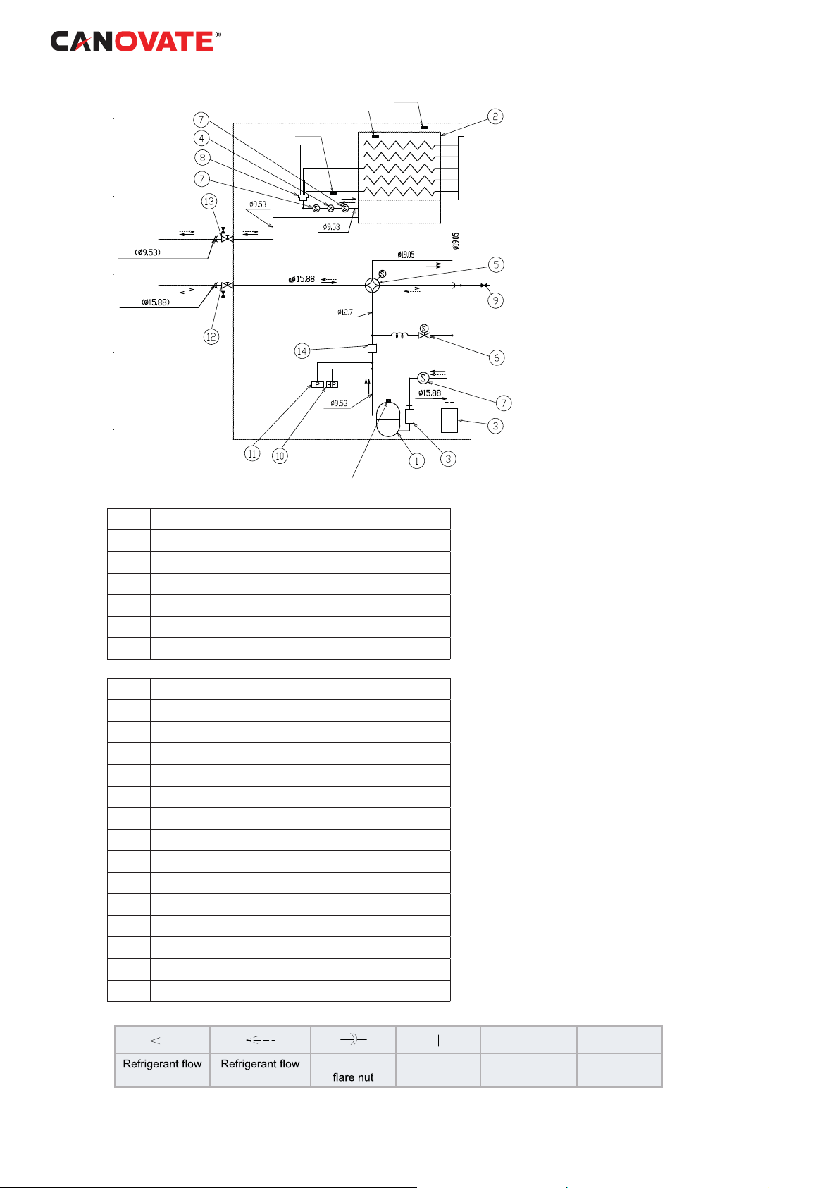
Evacuation and refrigerant charge
- Connect the gauge manifold using charging
hoses with a vacuum pump or a nitrogen cylinder to
the check joints of the liquid line and the gas line stop
valve.
- Check for any gas leakage at the fl are nut connection,
by using nitrogen gas to increase the pressure at
4.15 MPa for outdoor units inside of the fi eld-supplied
piping.
- Operate the vacuum pump for 1 to 2 hours until the
pres- sure decreases lower than a pressure of 756
mmHg in vacuum.
- For charging refrigerant, connect the gauge manifold
us- ing charging hoses with a refrigerant charging
cylinder to the check joint of the liquid line stop valve.
- Charge the proper quantity of refrigerant according
to the piping length (Calculate the quantity of the
refrigerant charge).
- Fully open the gas line stop valve, and slightly open
the liquid line stop valve.
- Charge refrigerant by opening the gauge manifold
valve.
- Charge the required refrigerant within the difference
range of ±0.5kg by operating the system in cooling.
- Fully open the liquid line stop valve after completing
refrig- erant charge.
- Continue cooling operation for more than 10 minutes
to circulate the refrigerant.
Thermal insulation
Gas line
Outdoor unit
Manifold
gauge
Vacuum cylinder
Example of Evacuation and Refrigerant Charge.
40 l Can BREEZE Operating and Maintenance Cooling Unit Instructions 8-14 kW
Liquid line
Liquid stop valve
Gas stop valve
Nitrogen tank
(For air Tight test
& Nitrogen blow
during brazing)
of the piping connection with
thermal insulation
Insulate the liquid pipe for
prevention of the capacity
decrease according to the
ambient air conditions and
the dewing on the pipe surface by the low pressure
www.canovate.com l info@canovate.com l P. +90 216 484 2222
18.4 Refrigerant charge
CAUTION
Do not charge OXYGEN, ACETYLENE, or other
fl ammable and poisonous gases into the refrigerant
because an explosion can occur. It is recommended
that oxygen free nitrogen be charged for these types
of tests cycle when performing a leakage test or an
airtight test. These types of gases are extremely
dangerous, Insulate the unions and fl are-nuts at the
piping connection part completely.
Insulate the liquid piping completely to avoid a
decrease of performance;
if not, it will cause sweating on the surface of the pipe.
Charge refrigerant correctly. Overcharging or
insuffi cient charging could cause a compressor
failure.
Check for refrigerant leakage in detail. If a large
refrigerant leakage occurred, it would cause diffi culty
with breathing or harmful gases would occur if a fi re
were being used in the room.
If the fl are nut is tigthened too hard, the fl are nut may
crack after a long time and cause refrigerant leakage.
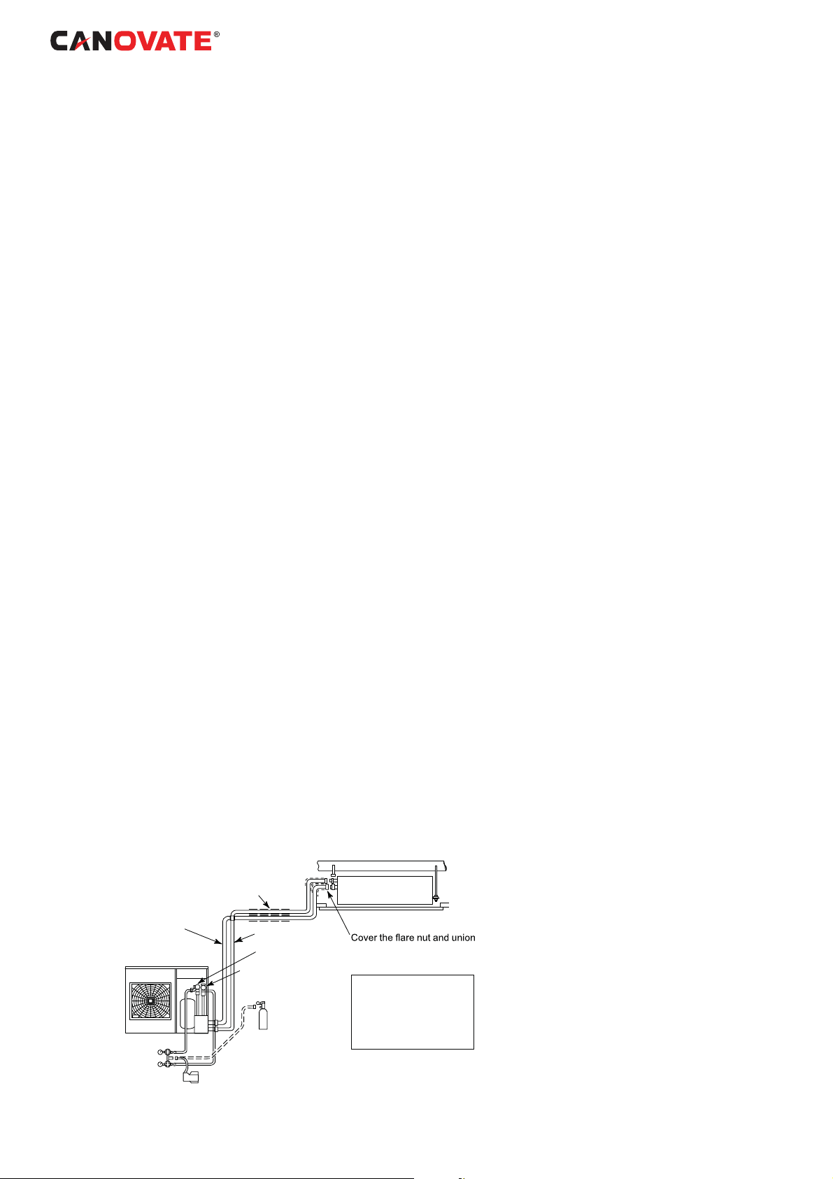
18.5 Caution of the pressure by check
joint
When the pressure is measured, use the check joint
of gas stop valve (A), and use the check joint of liquid
piping (B) in the fi gure below.
At that time, connect the pressure gauge according to
the following table because of high pressure side and
low pressure side changes by operation mode.
NOTE
Be careful that refrigerant and oil do not splash to the
electrical parts at removing the charge hoses.
The gas stayed at O-ring
screw part is opened
and may make sound
B
However, it is not gas
leakage.
C
A
.pac eht gnivomer nehw
18.6 Refrigerant Charging Quantity
Outdoor Units has been charged with refrigerant for
30m of actual piping length. An additional refrigerant
charged is required in systems with actual piping
length longer than 30m.
www.canovate.com l info@canovate.com l P. +90 216 484 2222
1
Determine an additional refrigerant quantity
according to the following procedure, and charge it
into the system.
2 Record the additional refrigerant quantity to facilitate
service activities thereafter.
Can BREEZE Operating and Maintenance Cooling Unit Instructions 8-14 kW l 41
CAUTION
When charging refrigerant accurately measure
refrigerant to be charged.
Overcharging or undercharging of refrigerant can
cause compressor trouble
In case of actual piping length less than 5 m, consult
your distributor
.
18.7
ELECTRICAL WIRING CONNECTION
FOR OUTDOOR UNITS
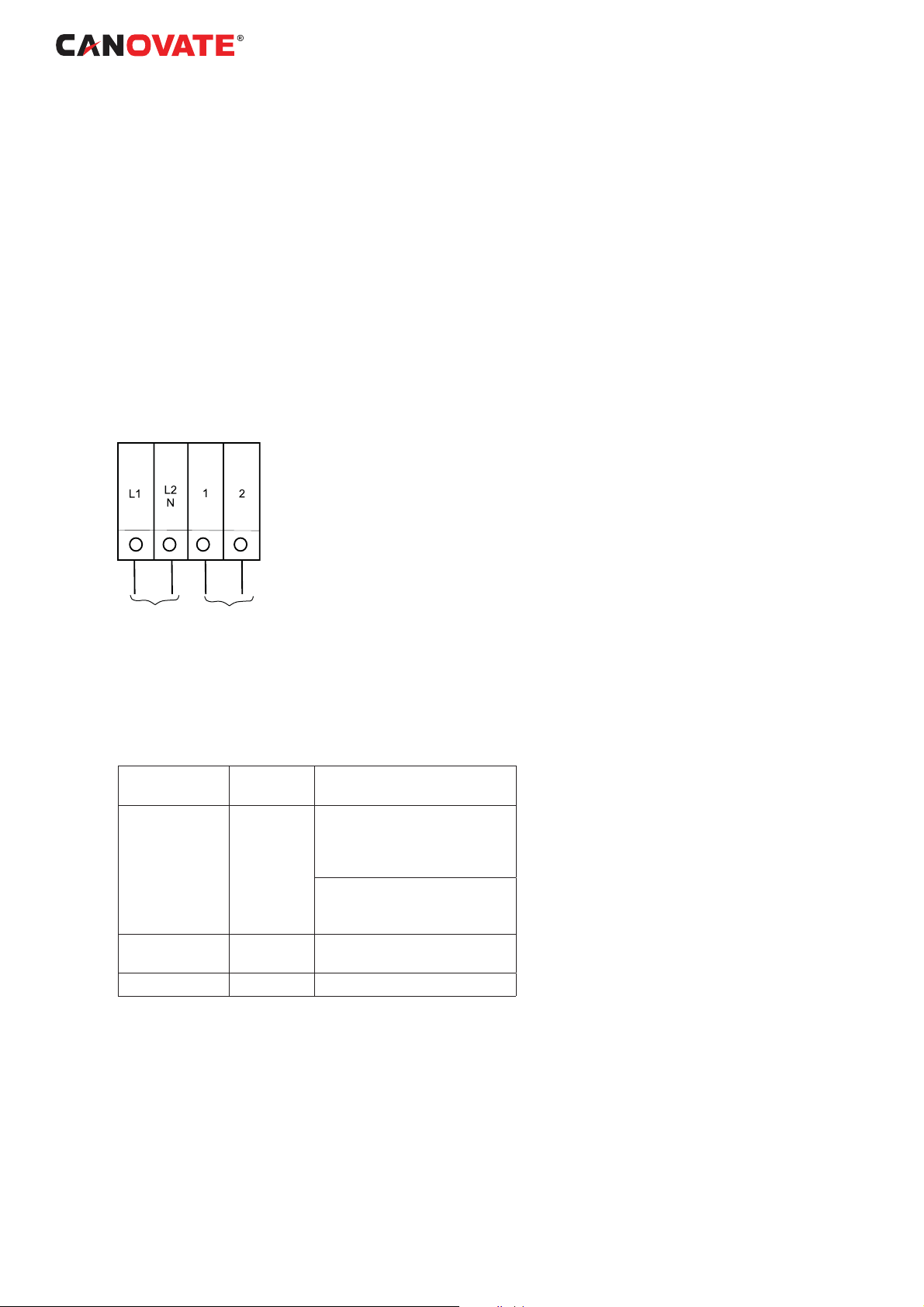
The electrical wiring connection for the outdoor unit is
shown in fi gure
8-14 kW
1~ 230V
Power supply
below:
Control cable (5V)
able for Terminal Connection between units
T
Wiring
Power Supply DC inverter O.U. to O.U.
Operating DC inverter O.U. to I.U. or I.U. toI.U. 1 to1,
Remote Control DC inverter I.U. to I.U. A to A, B to B
System Units type Connection of
terminals
L1 to L1, L2 to L2, L3 to L3,
N to N
I.U. to I.U.
L1 to L1, N to N)
2 to 2
42 l Can BREEZE Operating and Maintenance Cooling Unit Instructions 8-14 kW www.canovate.com l info@canovate.com l P. +90 216 484 2222

18.7.3
Setting of DIP Switches for Outdoor
Unit
Quantity and Position of DIP
is as follows:
Switches. The location
DSW1: For T
Factory setting
est Run
DSW2: Optional Function Setting
Factory setting
3LSLQJOHQJWKP
3LSLQJOHQJKWP
Optional function setting
Optional function setting
ON
1 2 4 6
([WHUQDOLQSXWRXWSXWVHWWLQJPRGH
www.canovate.com l info@canovate.com l P. +90 216 484 2222 Can BREEZE Operating and Maintenance Cooling Unit Instructions 8-14 kW l 43

DSW3: Capacity
Factory setting
8 kW
ON
1 2 3 4 5 6
8 kW
ON
1 2 3 4 5 6
DSW5: T
ransmission Setting of End Terminal
14 kW
ON
1 2 3 4 5 6
14 kW
ON
1 2 3 4 5 6
Resistance
Factory setting
Cancellation
In the case that the outdoor units quantity in the same
H-LINK is 2 or more, set No. 1 pin of DSW5 at “OFF”
side from the 2nd refrigerant group outdoor unit. If
only one outdoor unit is used, no setting is required.
Refrigerant Cycle No. Setting
DSW6: Optional function setting (IVX series only)
For individual operation
(factory setting position)
For IVX series
For simultaneous operation
DSW4
Factory setting
(Setting for the ten digit).
DSW6: Not available for ES series
tpmEy
Factory setting
or
RSW1
44 l Can BREEZE Operating and Maintenance Cooling Unit Instructions 8-14 kW www.canovate.com l info@canovate.com l P. +90 216 484 2222
Factory setting
(Setting for the last digit).
0
1
9
2
8
3
7
4
6
5
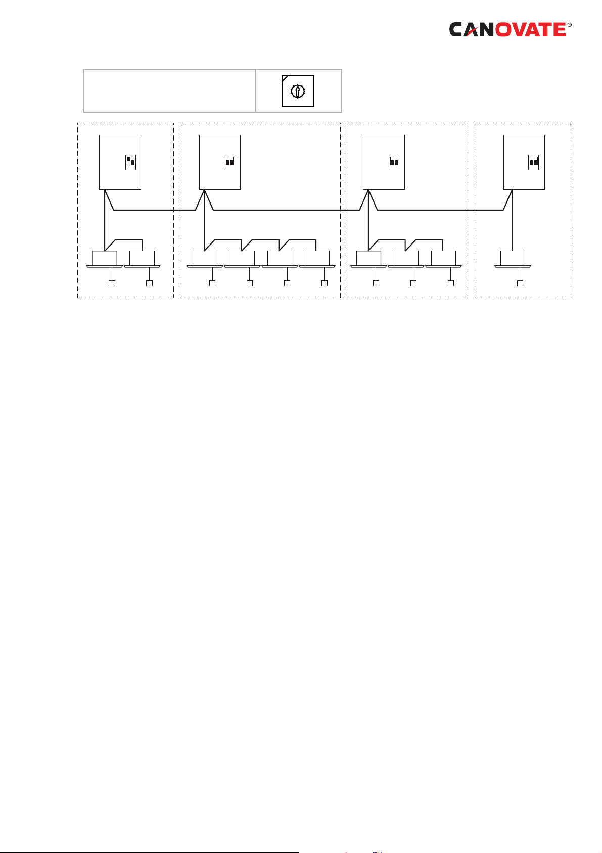
18.7.4
System installation DIP Switch
DSW5
12
H-LINK) ( H-LINK)
(
DSW5
12
Setting
Dip Switch Setting of Indoor PCB and Outdoor PCB
for H-LINK II
It is required to set dip switches of every indoor unit
and outdoor unit and match of the transmission circuit
impedance.
•
Dip Switch Setting Example:
DSW5
12
DSW5
12
( H-LINK)
www.canovate.com l info@canovate.com l P. +90 216 484 2222 Can BREEZE Operating and Maintenance Cooling Unit Instructions 8-14 kW l 45
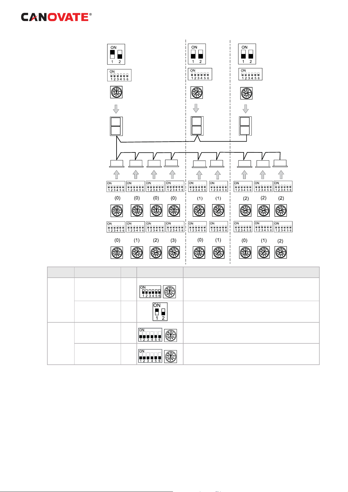
DSW5
Terminating Resistance
DSW4
Refrigerant Cycle Nº
(Setting for ten digit)
RSW1
Refrigerant Cycle Nº
(Setting for last digit)
Outdoor units
Indoor units
DSW5
Refrigerant Cycle Nº
(Setting for ten digit)
RSW2
Refrigerant Cycle Nº
(Setting for last digit)
DSW6
Indoor unit Address
(Setting for ten digit)
Cycle nº 0
Cycle nº 1
Cycle nº 2
RSW1
Indoor unit Address
(Setting for last digit)
Unit Name of Dip Switch Mark
Refrigerant Cycle
Outdoor Unit
Terminating Resistance DSW5
Refrigerant Cycle
Indoor Unit
Indoor Unit Address
DSW4
RSW1
DSW5
RSW2
DSW6
RSW1
Setting Before
Shipment
DSW4 RSW1
DSW5 RSW2
DSW6 RSW1
Function
For setting refrigerant cycle address of Outdoor Unit. Set the DSW4
and RSW1 not to overlap the setting of other Outdoor units in the same
H-LINK system
For matching impedance of transmission circuit, set the DSW5 according to the quantity of outdoor units in the H-LINK system.
For setting refrigerant cycle address of indoor units. Set the DSW5 and
RSW2 corresponding to the address of outdoor unit in the same refrigerant cycle.
For setting indoor unit address. Set the DSW6 and RSW1 not to overlap
the setting of other indoor units in the same refrigerant cycle. (If not set,
the automatic address function is performed).
46 l Can BREEZE Operating and Maintenance Cooling Unit Instructions 8-14 kW
www.canovate.com l info@canovate.com l P. +90 216 484 2222

19. TEST RUNNING
When installation is completed, perform test run
according to the following procedure, and hand
over the system to the customer. Perform test run
regarding indoor units one by one in order, and
confi rm that the electrical wiring and the refrigerant
piping are correctly connected.
Test run should be performed according to the Test
Run Proce- dure on next page.
C A U T I O N
Do not operate the system until all the check points
have been cleared:
• Check to ensure that the electrical resistance
is more than 1 MΩ, by measuring the resistance
between ground and the terminal of the electrical
parts. If not, do not operate the sys- tem until the
electrical leakage is found and repaired. Do not
impress the voltage on the terminals for transmission
1 and 2.
• Check to ensure that the stop valves of the
outdoor unit are fully opened, and then start the
system.
• Check to ensure that the switch on the main
power source has been ON for more than 12 hours,
to warm the compressor oil by the oil heater
Pay attention to the following items while the system
is running:
• Do not touch any of the parts by hand at the
discharge gas side, since the compressor chamber
and the pipes at the dis- charge side are heated
higher than 90°C.
• DO NOT PUSH THE BUTTON OF THE
MAGNETIC SWITCH(ES), it will cause a serious
accident.
• Do not touch any electrical components for
more than three minutes after turning OFF the main
switch
• Confi rm that the gas line stop valve and the
liquid line stop valve are fully open.
• Confi rm that the leakage of the refrigerant does
not exist. The fl are nuts are sometimes loosened by
vibration during trans- portation.
• Check that the refrigerant piping and the
electrical wiring con- form to the same system.
• Confi rm that the dip switch setting on the
printed circuit board of the indoor units and the
outdoor units are correct.
• Check whether or not the electrical wiring of
the indoor units and the outdoor units are connected
as shown in the chapter Electrical Wiring.
www.canovate.com l info@canovate.com l P. +90 216 484 2222
Can BREEZE Operating and Maintenance Cooling Unit Instructions 8-14 kW l 47

A U T I O N
C
Confi rm that fi eld-supplied electrical components
(main switch fuse, fuse-free breaker, earth leakage
breakers, wires, conduit connectors and wire
terminals) have been properly selected ac- cording
to the electrical data given in the Technical Catalog of
the unit and ensure that the components comply with
national and local codes.
N O T E
• For more reference check Troubleshooting
chapter on Opera- tion Part.
• For twin, triple and quad check the indoor unit
outlet air tem- perature at test run. If the temperature
difference is large (aprox. 10 deg. or more (cooling)
20 deg. or more (heating) recheck the refrigerant
piping, Installation may have some problem.
• In the case of anual cooling optional function,
cut JP1 out and set the DSW6-1 to OFF. (Individual
control is not available when anual cooling is
selected).
48 l Can BREEZE Operating and Maintenance Cooling Unit Instructions 8-14 kW www.canovate.com l info@canovate.com l P. +90 216 484 2222
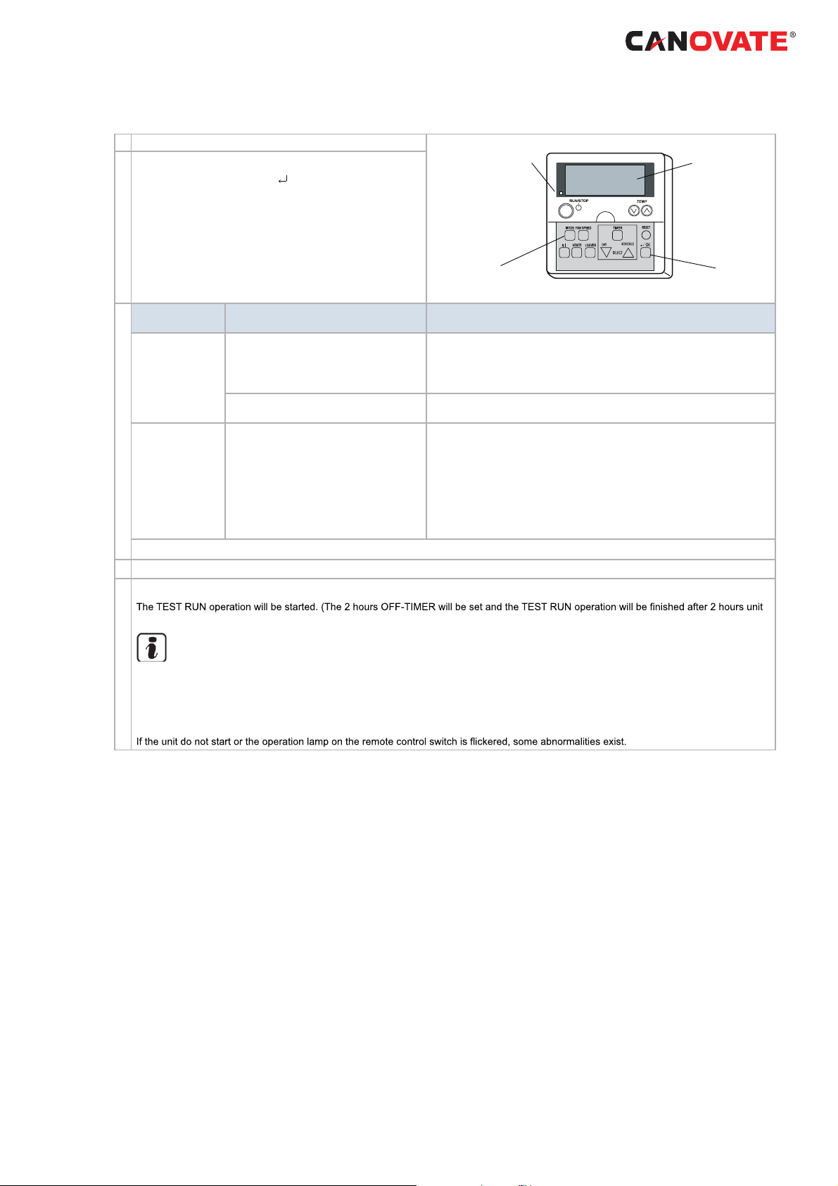
19.1 TEST RUN PROCEDURE BY REMOTE
CONTROL SWITCH (PC-ART EXAMPLE)
Turn ON the power source of the Indoor and Outdoor Units
Ƒ
Set the TEST RUN mode by remote control switch.
Depress the “MODE” and the “
for more than 3 seconds.
If “TEST RUN” and the counting number of the connect-
a.
Ƒ
Ƒ
Ƒ
ed units to the remote control switch (for example
are indicated on the remote control switch, the connec-
tion of remote control cable is correct.ĺGo to
If no indication appear or the number of the units indicat-
b.
ed is smaller than the actual number of the units, some
abnormalities exist.ĺGo to
Remote Control
Switch Indication
The power source of Outdoor Unit is not
turned ON.
No indication
Counting number
of connected units
is incorrect
Back to
Ƒ after checking
Select TEST RUNNING MODE by depressing MODE Switch (COOL OR HEAT)
Depress RUN/STOP switch.
The connection of the remote control cable
is incorrect.
The connecting wires of power supply line
are incorrect or loosened.
The power source of Outdoor Unit is not
turned ON.
The operating line wiring between indoor
unit and outdoor unit is not connected.
The connection of control cables between
each indoor units are incorrect. (When
one remote control switch controls multiple
units)
OK” switches simultaneously
“05”)
Ƒ
Ƒ
Wrong Portions Inspection Points after Power Source OFF
1
Connecting Points of Remote Control Cable terminal board of Remote
Control switch and indoor unit.
Contact of Terminals of Remote Control Cable
2
3
Connection Order of each Terminal Board
Screw Fastening of each Terminal Boards.
4
5
Dip Switch Setting on Printed Circuit Board
Connecting on the PCB
6
7
This is the same as item Ƒ 1, 2 , and 3.
Operation lamp
05
Counting
number of
connected
units
operation or by depressing the RUN/STOP switch again).
Ƒ
NOTE
TEST RUN operation ignores the temperature limitation and ambient temperature during heating operation to have a continuous
operation, but the protections are alive. Therefore, the protection may activate when the heating TEST RUN operation is performed
in high ambient temperature.
TEST RUN operation time can be modifyed / increased depressing the time switch in the Remote Control.
Ƒ
ĺGo to
www.canovate.com l info@canovate.com l P. +90 216 484 2222
Can BREEZE Operating and Maintenance Cooling Unit Instructions 8-14 kW l 49

Remote Control
Switch Indication
Unit Condition Wrong Portions
Inspection Points after
Power Source OFF
1
Connecting Order of each Terminal
Board.
2
Screw fastening of each Terminal
Boards.
ers. (1 time/1 sec.) And
the Unit No. and Alarm
The unit does not start.
6
-
ers. (1 time/2 sec.)
Indication of Flicker
except above
The operation lamp
Flickers. (1 Time/1s)
00
Unit No.
Code and Unit Code
, Alarm
The unit does not start.
The unit does not start, or start once
and then stops
The unit does not start.
E00
after checking
1
Back to
Instructions fot the recovery when the fuse of the transmission
circuit is blown out:
7
1
Correct the wiring to the terminal board.
Set the 1st pin of DSW7 on the indoor unit PCB to ON.
2
The power source of Outdoor
Unit in not turned ON.
The connecting wires of operating
line are incorrect or loosened.
Remote control cable is broken.
Contact of connectors is not
good.
The connection of remote control
cable is incorrect
The connection of thermistor or
other connectors are incorrect.
Tripping of protector exists, or
else.
The connection of the remote
control cable between Indoor
Units is incorrect.
NOTE
Recovering method of FUSE for operating circuit. There is a fuse (FUSE4
on Indoor Unit PCB1, EF1 on Outdoor
Unit PCB1) to protect operating circuit on the PCB, when the power lines
are connected to operating lines. If
fuse is melted, operating circuit can
be recovered once by setting the dip
switch on the PCB as shown in
This is the same as item
Check by the abnormality mode table in
the Technical Catalogue (Do it by service people).
Check by the abnormality mode table in
the Technical Catalog (Do it by service
people).
1 and 2
3
7
19.2 TEST RUN FROM OUTDOOR UNIT
SIDE
The procedure of test run from outdoor unit side
is indicated be- low. Setting of this DIP switch is
available with the power source ON.
Setting of Dip Switch (Before Shipment)
DSW1
Switch for setting of Serivice Operation and Function
1 Test Run
2 COOL/HEAT
3 OFF (Fixed)
4 Manual Compressor stop
C A U T I O N
• Do not touch any other electrical parts when
operating switch-
es on the PCB
• Do not attach or detach service cover when
the power source for the outdoor unit is ON and the
outdoor unit is operated.
• Turn all DIP switches of DSW1 OFF when the
test run opera- tion is completed.
Setting ON: Heat Operation
50 l Can BREEZE Operating and Maintenance Cooling Unit Instructions 8-14 kW
www.canovate.com l info@canovate.com l P. +90 216 484 2222
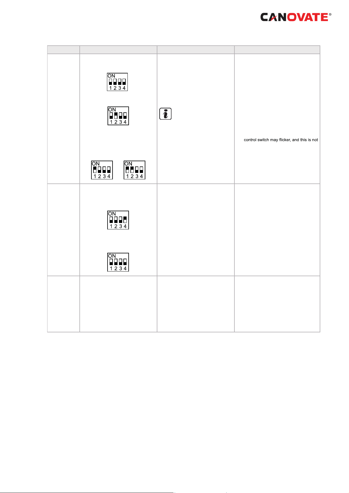
Operation Dip Switch Setting Operation Remarks
Take care that the indoor units start operation in accord with the test run operation of the outdoor unit.
The test run is started from the outdoor
unit and stopped from the remote control switch, the test run function of the
remote control switch is cancelled. However, the test run function of the outdoor
unit is not cancelled
In case that the plural indoor units are
connected with one remote control
switch, all the units start test run operation at the same time, therefore, turn the
power source OFF for the indoor units
not to operate test run. In this case, the
“TEST RUN” indication of the remote
abnormal.
The setting of DSW1 is not required
for the test run from the remote control
switch.
Do not repeat compressor ON/OFF fre-
quently.
Test Run
Manual OFF of
Compressor
1 Setting of Operation Mode:
Cooling: Set DSW1-2 OFF.
Heating: Set DSW1-2 ON.
2 Starting Test Run:
Set DSW1-1 ON and the operation is
started after a few ~20 seconds.
Cooling Heating
1 Setting:
Compressor Manual OFF:
Set DSW1-4 ON.
Compressor ON:
Set DSW1-4 OFF.
1 The indoor unit automatically start to
operate when the test run of the outdoor
unit is set.
2 The ON/OFF operation can be performed from the remote control switch or
DSW1-1 of the outdoor unit.
3 Continuous operation during 2 hours
is performed without Thermo-OFF.
NOTE
TEST RUN operation time can be
increased depressing the time
switch in the Remote Control.
If is setting DSW1-3 ON, cool-
ing/heating intermediate season
mode is activaded.
1 When DSW1-4 is ON during compressor operation, the compressor stops
to operate immediately and the indoor
unit is under the condition of ThermoOFF.
2 When DSW1-4 is OFF, the compressor starts to operate after the cancellation of 3-minutes guard.
Manual Defrost
1 Manual Defrost Operation Starts
Press PSW1 for more than 3 seconds
during heating operation, the defrost
operation is started after 2 minutes.This
function is not available within 5 minutes
after starting heating operation
2 Manual Defrost Operation Finishes
Defrost operation is automatically ended
and the heating operation is started.
1 Defrost operation is available regardless of frosting condition and total
time of heating operation.
2 Defrost operation in not performed
when the temperature of outdoor heat
exchanger is higher than 10°C, high
pressure is higher than 3.3 MPa (33kgf/
2
G) or Thermo-OFF.
cm
Do not repeat defrost operation frequent-
ly.
www.canovate.com l info@canovate.com l P. +90 216 484 2222
Can BREEZE Operating and Maintenance Cooling Unit Instructions 8-14 kW l 51

20. Specifi cations
Power supply
Nominal Cooling Capacity (min - max)
UK Cooling Capacity (sensible)
Outdoor Unit
8 kW
14 kW
230V / 1Ph / 50Hz 230V / 1Ph / 50Hz
(4)
kW 7.7 (6.2) 13.2 (9.5)
kW 7.1 (3.2 - 8.0)
12.5 (5.7 - 14.0)
Minimum - Maximum Indoor Units* 1 - 2 1 - 4
Minimum - Maximum connected capacity* 90%-110% 90% - 115%
Seasonal Eciency SEER
(2)
5.31 n/a
Energy Eciency Class A -
Annual Energy Consumption kWh/yr 469 n/a
Seasonal Eciency SCOP
(Average Climate)
(2)
4.07 n/a
Energy Eciency Class A+ -
Annual Energy Consumption kWh/yr 1912 n/a
Nominal Load Eciency EER / COP
(3)
3.14 / 4.00 3.16 / 3.88
Energy Class (Cool/Heat) B / A B / A
Dimensions (H x W x D) mm 600x792x300 800x950x370
Weight Kg 44 79
Piping diameter (Liquid / Gas)
Inch 3/8 / 5/8 3/8 / 5/8
mm 9.53 / 15.88 9.53 / 15.88
Minimum Piping Length m 5 5
Maximum Piping Length / Height Dierence m 50 / 30 75 / 30
Working Range (cooling / heating) °C -5°C~46(db)°C / -20°C~15(wb)°C
* Restrictions apply please refer to Technical Catalogue
(1)
Sound power level is the A-weighted sound power level [dB(A)] measured at standard rated
conditions for the “cooling” mode operation in accordance to EN12102
(2)
Data calculated in accordance to prEN14825 and the Commission Communication 2012/C 172/01
(3)
Nominal load eciency (Cooling 35°C/27°C, Heating 7°C/20°C)
(2, 3 & 4)
Data specied includes connection to RCI-FSN3 indoor unit
Indoor Unit 7 kW
Nominal Cooling Capacity
Noise Level (sound pressure) (L / M / H)
Noise level (sound power) dB(A) 65
Air ow cooling mode (L / M / H) m
Included Condensate Pump no
Drain Diameter (ext) ij25mm
Piping Diameter (Liquid / Gas)
Power Input W 170
Power supply 230V / 1Ph / 50Hz
Recommended fuse size A 5
(1)
Cooling: Internal ambient 27°C (19°C WB) - Ambient 35°C; Refrigerant piping length 7.5m, level dierence 0m.
(2)
Sound pressure level measured at 1.5 meters below the unit (measured in anechoic room)
(1)
(2)
kW 7.1
dB(A) 42/45/48
3
/h 900/1020/1260
Inch 3/8 / 5/8
mm 9.53 / 15.88
41/46/49
1260/1680/2100
9.53 / 15.88
230V / 1Ph / 50Hz
14 kW
14.0
65
no
ij25mm
3/8 / 5/8
230
5
52 l Can BREEZE Operating and Maintenance Cooling Unit Instructions 8-14 kW
www.canovate.com l info@canovate.com l P. +90 216 484 2222

21. TROUBLESHOOTING
Alarm Code Indication of Remote Control Switch:
Abnormal
Indoor Unit
No.
COOL
Abnormal
Ref. Cycle
No. Alarm Code Model Code
MED
A/C ALARM
ADDS. RN
Indicated
for a second alter-
nately
Connected
No. of Indoor
Units
COOL
MED
A/C ALARM
P
ADDS. RN
Alarm
Code
Model Code
Indication Model
Heat-Pump
Inverter
Multi (Set-Free)
Cooling Only
Others
2, 3 and 4 indoor units
system
www.canovate.com l info@canovate.com l P. +90 216 484 2222
Can BREEZE Operating and Maintenance Cooling Unit Instructions 8-14 kW l 53

Code
No.
01 Indoor Unit Tripping of Protection Device
02 Outdoor Unit Tripping of Protection Device Activation of PSH, Locked Motor
03
04 Abnormality between Inverter and Control PCB Failure in Transmission between PCBs for Inverter
05 Power Supply Abnormality power supply Abnormal wave form of power supply.
06 Voltage Drop
07
08 Increase in Discharge Gas Temperature
11
12 Outlet Air Thermistor
13 Freeze Protection Thermistor
14 Gas Piping Thermistor
19 Tripping of Protection Device for Fan Motor Failure of Fan Motor
20
21 High Pressure Sensor
22 Out+door Air Thermistor
24 Evaporating Thermistor
31
35 Incorrect Setting in Indoor Unit No.
38 Abnormality of Protective Circuit in Outdoor Unit
45
47
48
51 Abnormality of Current Sensor for Inverter Failure of Control PCB, Inverter Module.
53 Protection Activation of Transistor Module
54 Inverter Fin Temperature Increase
55 Inverter Module Abnormality Failure of Inverter Module.
57 Outdoor Fan Fan Motor Abnormality
b1
EE Compressor Compressor protection alarm Failure of compressor.
Category Content of Abnormality Leading Cause
Failure of Fan Motor, Drain Discharge, PCB, Relay, Float Switch
Activated
Transmission
Cycle
Sensor on
Indoor Unit
Sensor on
Outdoor Unit
System
Pressure
Inverter
Indoor unit No.
setting
Abnormality between Indoor (or Outdoor) and
Outdoor (or Indoor)
Voltage Drop by Excessively Low or High Voltage to Outdoor Unit
Decrease in Discharge Gas Superheat Excessive Refrigerant Charge, Expansion Valve Open Lock
Inlet Air Thermistor
Compressor Thermistor
Incorrect Setting of Outdoor and Indoor Unit Incorrect Setting of Capacity Code.
Activation of High Pressure Increase Protection
Device
Activation of Low Pressure Decrease Protection
Device
Activation of overload protection
Incorrect address No. Setting or refrigerant
cycle
Incorrect Wiring, Failure of PCB, Tripping of Fuse, Power Supply
OFF
ity of Power Supply Wiring
Close Lock
Failure of Thermistor, Sensor, Connection.
Failure of Thermistor, Sensor, Connection
(Incorrect Wiring, disconnecting wiring, breaking wire, short circuit)
tions.
Failure of Indoor Unit PCB. Incorrect wiring. Connection to PCB in
Indoor Unit.
Overload Operation (Clogging, Short-Pass), Pipe Clogging, Exces-
sive Refrigerant, Inert Gas Mixing
Stoppage by Excessively Decrease of evaporating Temperature
(Te < -35ºC) is activated 3 times in one hour, Locked Motor in Heating Operation.
Failure of IPM or PCB2, heat exchanger clogged, locked compressor, EVI/EVO failure or overcharge.
Transistor Module Abnormality.
Failure of Compressor, clogging of Heat Exchanger.
Abnormal Inverter Fin Thermistor.
Clogging of Heat Exchanger
Abnormal Outdoor Fan
Disconnected wire of Incorrect wiring between Control PCB and
Inverter PCB.
Incorrect Wiring or Fan Motor Abnormality
Over 64 indoor units setting by No. or indoor unit address.
-
-
54 l Can BREEZE Operating and Maintenance Cooling Unit Instructions 8-14 kW
www.canovate.com l info@canovate.com l P. +90 216 484 2222

www.canovate.com l info@canovate.com l P. +90 216 484 2222 Can BREEZE Operating and Maintenance Cooling Unit Instructions 8-14 kW l 55

canovatesales
www.linkedin.com/company/canovate-group
www.facebook.com/canovategroup
Get connected :www.canovate.com
© Copyright 2016 Canovate Group, The information contained herein is subject
to change without notice. The only warranties for Canovate products and services are
set forth in the express warranty statements accompanying such products and
services. Nothing herein should be construed as constituting an additional warranty.
Canovate shall not be liable for technical or editorial errors or omissions contained
herein.
www.canovate.com l info@canovate.com l P. +90 216 484 2222
Document Name:Can BREEZ E operating and Maintenance Cooling Unit Instructions 8-14 kWPu Publication Date:05/08/15
IT’s
far and away
the BEST
56 l
 Loading...