


We’re here to help 866-558-5706
Hrs: M-F 9am to 5pm EST
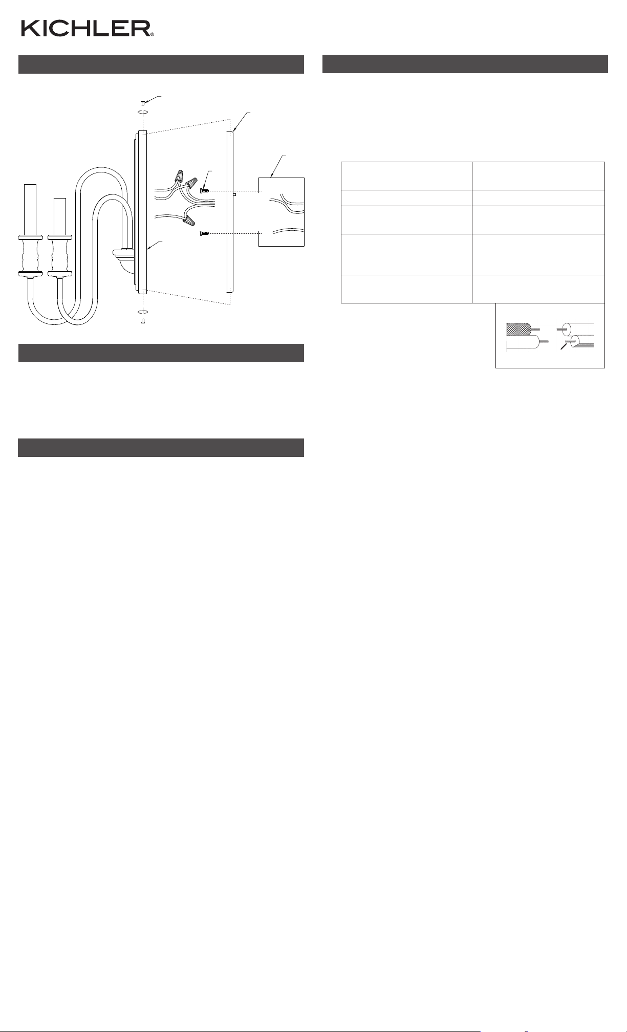
FIXTURE DIAGRAM
D
A
C
E
PARTS LIST
[A] Mounting
Strap
[B] Outlet Box
[C] Strap
Mounting
Screw (2)
[D] Countersunk
Mounting
Screw (2)
[E] Canopy
CAUTIONS
CAUTION – RISK OF SHOCK:
Disconnect Power at the main circuit breaker panel or main
fusebox before starting and during the installation.
WARNING:
1. This fixture is intended for installation in accordance
with the National Electrical Code (NEC) and all local
code specifications. If you are not familiar with code
requirements, installation by a certified electrician is
recommended. Failure to adhere to these codes and
instructions may result in serious injury and/or property
damage and will void the warranty.
CLEANING:
• Always be certain that electric current is turned o before
cleaning.
• Only a soft damp cloth should be used. Harsh cleaning
products may damage the finish.
INSTALLATION INSTRUCTIONS
1. Pass supply wires through center hole in mounting strap[A].
2. Attach mounting strap to outlet box[B] using the strap mounting
screws[C]. Mounting strap should be mounted with the threaded holes
at the far edges of the mounting strap in the 12 and 6 o’clock position.
3. Grounding instructions: (See Illus. a or b).
a. On fixtures where mounting strap is provided with a hole and two
B
4. Make wire connections. Reference chart below for correct connections
5. Push fixture to wall, carefully aligning the threaded holes in the top
6. Screw two (2) countersunk mounting screws[D] into the holes in the
7. Inser t recommended bulbs (not included).
raised dimples, wrap ground wire from outlet box around green
ground screw, and thread into hole.
b. On fixtures where a cupped washer is provided, attach ground wire
from outlet box under cupped washer and green ground screw, and
thread into mounting s trap.
If fixture is provided with ground wire, connect fixture ground wire to
outlet box ground wire with wire connector af ter following the above
steps. Never connect ground wire to black or white power supply wires.
a
OUTLET BOX
GROUND
DIMPLES
GREEN GROUND
SCREW
and wire accordingly.
Connect Black or Red
Supply Wire to:
WIRE CONNECTOR
FIXTURE
GROUND
OUTLET BOX
GROUND
GREEN GROUND
SCREW
Connect White Supply
Wire to:
b
FIXTURE
GROUND
CUPPED
WASHER
Black White
*Parallel cord (round &
smooth)
Clear, Brown, Gold or Black
without Tracer
Insulated wire (other
than green) with copper
conductor
*Parallel cord (square &
ridged)
Clear, Brown, Gold or Black
with Tracer
Insulated wire (other
than green) with silver
conductor
*Note: When parallel wire (SPT
1 & SPT 2) are used. The neutral
wire is square shaped or ridged
and the other wire will be round
in shape or smooth (See illus.) Neutral Wire
and bottom of mounting strap[A] with holes in the top and bottom of
canopy[E].
NOTE: Fixture should be mounted with candles in the up position. Make
sure all wires are inside canopy and do not get pinched between wall and
canopy of fixture.
canopy and mounting strap to attach fixture to wall. One at the top and
one at the bottom. Tighten to secure.
REV 4-NOV-2021
For warranty information please visit: kichler.com/warranty
IS-52473-US
For Assembling and Installing Fix tures in Canada
Pour L’assemblage et L’installation Au Canada
INSTRUCTIONS:
Nous sommes là pour vous aider 866-558-5706
Heures : du lundi au vendredi, de 9h à 17h (heure de l’Est)
DIAGRAMME D’APPAREILS
D
A
C
E
LISTE DES PIÈCES
[A] Étrier de
Montage
[B] Boite de
Sortie
[C] Vis de
Montage de
L’étrier (2)
[D] Vis de
Montage à
Tête Fraisée
(2)
[E] Cache
PRÉCAUTIONS
ATTENTION – RISQUE DE DÉCHARGES ÉLECTRIQUES:
Couper le courant au niveau du panneau du disjoncteur du
circuit principal ou de la boîte à fusibles principale avant de
procéder à l’installation.
INSTRUCTIONS D’INSTALLATION
1. Faites passer les f ils d’alimentation à travers le trou central de l’étrier de
montage[A].
2. Fixez l’étrier de montage sur la boîte de sortie[B] avec les vis de montage
de l’étrier[C]. L’étrier de montage doit être installé avec les trous filetés
sur les bords éloignés de la sangle de montage en position 12 et 6 heures.
3. Connecter les fils. Se reporter au tableau ci-dessous pour faire les
B
connexions.
Connecter le fil noir ou
rouge de la boite
Connecter le fil blanc de
la boîte
A Noir A Blanc
*Au cordon parallèle (rond
et lisse)
Au transparent, doré,
marron, ou noir sans fil
distinctif
Fil isolé (sauf fil vert) avec
conducteur en cuivre
*Au cordon parallèle (à
angles droits el strié)
Au transparent, doré,
marron, ou noir avec un til
distinctif
Fil isolé (sauf fil vert) avec
conducteur en argent
*Remarque: Avec emploi d’un
fil paralléle (SPT 1 et SPT 2). Le
fil neutre est á angles droits ou
strié et l’autre fil doit étre rond ou
lisse (Voir le schéma). Fil Neutre
4. Poussez le luminaire contre le mur en alignant soigneusement les trous
filetés en haut et en bas de l’étrier de montage[A] avec les trous en haut
et en bas du cache[E].
REMARQUE : Le luminaire doit être installé avec les bougies en position
verticale. S’assurer que tous les fils sont à l’intérieur du cache et ne sont
pas pincés entre le mur et le cache du luminaire.
5. Vissez deux (2) vis de montage à tête fraisée[D] dans les trous du cache
et de l’étrier de montage pour fixer le luminaire au mur. Une (1) en bas et
une (1) en haut. Serrez pour fixer.
6. Installez les ampoules recommandées (non fournies).
ATTENTION:
1. Ce luminaire doit être installé conformément aux codes
d’électricité nationaux (NEC) et satisfaire toutes les
spécifications des codes locaux. Si vous ne connaissez
pas les exigences de ces codes, il est recommandé de
confier l’installation à un électricien certifié. Ne pas se
conformer à ces codes et directives pourrait provoquer
des blessures sérieuses et/ou des dommages matériels et
rendre la garantie non valide.
NETTOYAGE :
• Soyez toujours certain que l’alimentation électrique du
luminaire est fermée avant le nettoyage.
• N’utilisez qu’un chion doux humide. Les produits de
nettoyage acides/abrasifs peuvent endommager le fini.
REV 4-NOV-2021
Pour de plus amples informations sur la garantie, veuillez visiter : kichler.com/warranty
IS-52473-CB

Estamos aquí para ayudarle 866-558-5706
Horario: Lunes-Viernes 9am a 5pm EST (hora oficial del este)
DIAGRAMA DE ACCESORIOS
LISTA DE PARTES
[A] Abrazadera
de Montaje
[B] Caja de Salida
[C] Tornillo de
Montaje de la
Abrazadera
(2)
INSTRUCCIONES DE INSTALACIÓN
1. Pase los cables de alimentación a través del orificio central de la
D
A
B
C
E
[D] Tornillo de
Montaje
Avellanado (2)
[E] Cubierta
abrazadera de montaje[A].
2. Fije la abrazadera de montaje a la caja de salida[B] utilizando los tornillos
de montaje de la abrazadera[C]. La abrazadera de montaje debe
montarse con los orificios roscados de los extremos de la abrazadera de
montaje en la posición de las 12 y las 6 horas en punto.
3. Instrucciones de conexión a tierra solamente para los Estados Unidos.
(Vea la ilustracion a o b).
a. En las lámparas que tienen la abrazadera de montaje con un agujero
y dos hoyuelos realzados, enrollar el alambre a tierra de la caja de
salida alrededor del tornillo verde y pasarlo por el aquiero.
b. En las lámparas con una arandela acopada, fijar el alambre a tierra
de la caja de salida del ajo de la arandela acoada y tornillo verde, y
paser por a abrazadera de montaje.
Si la lámpara viene con alambre a tierra, conecter el alambre a tierra
de la lámpara al alambre a tierra de la caja de salida con un conector
de alambres espués de seguir los pasos anteriores. Nunca conectar el
alambra a tierra a los alambres eléctros negro o blanco.
a
TIERRA DE LA
CAJA DE SALIDA
TORNILLO DE TIERRA,
VERDE
CONECTOR DE ALAMBRE
TIERRA
ARTEFACTO
DEPRESIONES
CAJA DE SALIDA
TIERRA DE LA
TORNILLO DE TIERRA,
VERDE
b
TIERRA
ARTEFACTO
ARANDELA
CONCAVA
PRECAUCIONES
PRECAUCIÓN – RIESGO DE DESCARGA ELÉCTRICA:
Desconecte la electricidad en el panel principal del
interruptor automático o caja principal de fusibles antes de
comenzar y durante la instalación.
ADVERTENCIA:
1. Este accesorio está destinado a la instalación de acuerdo
con el National Electrical Code (NEC) y todas las
especificaciones del código local. Si no está familiarizado
con los requisitos del código, la instalación se recomienda
un electricista certificado. No cumplir con estos códigos
e instrucciones puede resultar en lesiones graves y/ o en
daños a la propiedad y anulará la garantía.
LIMPIEZA:
• Asegúrese siempre de que la corriente eléctrica esté
apagada antes de limpiar.
• Debe usarse solamente un paño húmedo y suave.
Productos de limpieza abrasivos pueden dañar el acabado.
4. Haga les conexiones de los alambres. La tabla de referencia de abajo
indica las conexiones correctas y los alambres correspondientes.
Conectar el alambre de
suministro negro o rojo al
Conectar el alambre de
suministro blanco al
Negro Blanco
*Cordon paralelo (redondo
y liso)
Claro, marrón, amarillio
o negro sin hebra
identificadora
Alambre aislado (diferente
del verde) con conductor
de cobre
*Cordon paralelo (cuadrado
y estriado)
Claro, marrón, amarillio
o negro con hebra
identificadora
Alambre aislado (diferente
del verde) con conductor
de plata
*Nota: Cuando se utiliza alambre
paralelo (SPT 1 y SPT 2). El
alambre neutro es de forma
cuadrada o estriada y el otro
alambre será de forma redonda o
lisa. (Vea la ilustracíón). Hilo Neutral
5. Empuje el artefacto a la pared, alineando con cuidado los orificios
roscados en la parte superior e inferior de la abrazadera de montaje[A]
con los orificios en la par te superior e inferior de la cubierta[E].
NO TA: El artefacto debe montarse con las velas en la posición hacia
arriba. A segúrese de que todos los cables estén dentro de la cubierta y
que no queden atrapados entre la pared y la cubier ta del artefacto.
6. Enrosque dos (2) tornillos de montaje avellanados[D] en los orificios de la
cubierta y la abrazadera de montaje para fijar el ar tefacto a la pared. Uno
en la parte superior y otro en la inferior. Ajuste para asegurar.
7. Inser te los focos recomendados (no incluidos).
Para informacion de la garantia por favor visite: kichler.com/warranty
IS-52473-USREV 4-NOV-2021
 Loading...