

Page 1
PUB.DIE-0525-000
4K Camcorder
Instruction Manual
Page 2
COPYRIGHT WARNING
Trademark Acknowledgements
• SD, SDHC and SDXC Logos are trademarks of SD-3C, LLC.
• Microsoft and Windows are trademarks or registered trademarks of Microsoft Corporation in the United States and/or other countries.
• macOS is a trademark of Apple Inc., registered in the U.S. and other countries.
• HDMI, the HDMI logo and High-Definition Multimedia Interface are trademarks or registered trademarks of HDMI Licensing
Administrator, Inc. in the United States and other countries.
• Other names and products not mentioned above may be trademarks or registered trademarks of their respective companies.
• This device incorporates exFAT technology licensed from Microsoft.
• “Full HD 1080” refers to Canon camcorders compliant with high-definition video composed of 1,080 vertical pixels
(scanning lines).
• This product is licensed under AT&T patents for the MPEG-4 standard and may be used for encoding MPEG-4
compliant video and/or decoding MPEG-4 compliant video that was encoded only (1) for a personal and noncommercial purpose or (2) by a video provider licensed under the AT&T patents to provide MPEG-4 compliant video. No license is
granted or implied for any other use for MPEG-4 standard.
Unauthorized recording of copyrighted materials may infringe on the rights of copyright owners and be contrary to copyright
laws.
2
Page 3

Highlights of the Camcorder
The Canon XA45 / XA40 4K Camcorder is a high-performance camcorder whose compact size
makes it ideal in a variety of situations. The following are just some of the many functions featured in
the camcorder.
4K Recording
CMOS sensor and DIGIC DV 6 image
processor
The camcorder is equipped with a
1/2.3-inch CMOS sensor that captures video
at an effective pixel count of approximately
8.29 megapixels (3840x2160). The video is
then processed by the DIGIC DV 6 image
processor. In addition to recording 4K video,
the camcorder employs oversampling to
record Full HD video.
Wide zoom lens and 8-bladed aperture
The zoom lens is equipped with 20x optical
zoom and has a focal length at full wide angle
of 29.3 mm* (35 mm equivalent), making the
camcorder versatile in a variety of shooting
situations. The 8-bladed aperture delivers a
pleasing out-of-focus blur (“bokeh”) to your
recordings.
* When the resolution is 3840x2160 and the
image stabilization is a setting other than
Dynamic IS. The focal length is 30.6 mm
when using Dynamic IS.
4K recording at 29.97P and HD
recording at 59.94P
The camcorder can record clips in MP4 format
at 3840x2160 with a frame rate of 29.97P or
1920x1080 with a frame rate of 59.94P, giving
you the freedom to choose the video
configuration that is most suitable for your
project. Furthermore, audio is recorded as
either 4-channel linear PCM or 2-channel AAC.
Convenience and Functionality
Recording for extended periods
With its two SD card slots, the camcorder
allows you to use dual recording (A 32) to
record the same clip on two SD cards, or relay
recording to automatically switch to the other
SD card when the one being used becomes
full. Dual recording is a convenient way to
create a backup of your recordings while relay
recording effectively extends the available
recording time.
Emphasis on versatility
This camcorder has features to make it usable
as a main camera but is also small enough to
be very portable. The advanced image
stabilization (A 63), which stabilizes the
image along 5 axes, will let you shoot in a
variety of situations in the field. The handle unit
is removable so you can attach it to enjoy
additional audio options and infrared
functionality, or remove it when you need
improved portability. The LCD touch panel and
viewfinder can be angled in a variety of
positions, allowing for shooting in tight places,
for example.
Manual controls at your fingertips
The focus/zoom ring helps you achieve the
focus you are looking for. You can easily
change the ring's functionality so that you can
operate the zoom. You can also assign certain
frequently used functions to a customizable
button and adjust those functions with the
accompanying dial (A 84). Additionally, the
camcorder also features 5 assignable buttons
on the camcorder and one onscreen
assignable touch button to which you can
assign a variety of functions to access them
with ease (A 85).
3
Page 4

Face detection & tracking (A 61)
4
After detecting a subject's face, the camcorder
can focus on it and even track it. Furthermore,
the camcorder can be in manual focus but
switch to autofocus when a face is detected,
ensuring that important subjects are in focus.
Infrared recording
Record in darkness using infrared recording
(A 80). With the built-in infrared light on the
handle unit, you can record nocturnal animals
in their natural environment or other such
scenes.
Creativity and Artistic Expression
Special recording modes (A 38, 78)
When you make recordings, you can change
the recording frame rate to achieve a fast or
slow motion effect. Alternatively, you can use
pre-recording to record 3 seconds before you
decide to start recording, helping you capture
those hard-to-catch opportunities.
Looks (A 51)
You can adjust various aspects of the picture,
such as the color depth, sharpness and
brightness, to create a desired “look”.
Enhanced audio features (A 68)
The attachable handle unit offers expanded
audio options. It features two INPUT terminals
for external microphones (balanced input),
manual control over the audio recording level,
and control for supplying phantom power to an
external microphone
Other Features
• Battery packs compatible with Intelligent
System give you an estimate (in minutes) of
the remaining recording time.
• Compatibility with the optional GP-E2 GPS
Receiver to geotag your recordings (A 82).
• Compatibility with the optional RC-V100
Remote Controller (A 81) when you need a
professional level of remote control.
Page 5

Table of contents
1 Introduction 7
About this Manual 7
Conventions Used in this Manual 7
Supplied Accessories 9
Names of Parts 10
2 Preparations 15
Attaching the Ferrite Core 15
Charging the Battery Pack 15
Preparing the Camcorder 18
Attaching the Microphone Holder
Unit 18
Attaching the Handle Unit 18
Using the Lens Hood 19
Adjusting the LCD Screen 19
Using the Viewfinder 20
Grip Belt and Straps 21
Basic Operation of the Camcorder 23
Turning the Camcorder On and Off 23
Setting the Camera Mode 24
Using the MENU Button and
Joystick 24
First Time Settings 25
Setting the Date and Time 25
Changing the Language 26
Changing the Time Zone 26
Using the Menus 27
Setup Menus 27
FUNC Menu 28
Using SD Cards 30
Compatible SD Cards 30
Inserting and Removing an SD Card 31
Initializing an SD Card 32
Selecting the SD Card for
Recordings 32
Dual Recording and Relay Recording 32
Recovering Clips 33
3 Recording 34
Recording Clips and Photos 34
Basic Recording 34
Reviewing the Latest Clip Recorded 36
Video Configuration: Resolution, Bit Rate
and Frame Rate 37
Selecting the Resolution and Bit
Rate 37
Selecting the Frame Rate 37
Slow & Fast Motion Recording 38
Shooting Modes 39
Special Scene Modes 40
Exposure Adjustment 42
Manual Exposure (n)42
Automatic Exposure 43
Touch Exposure 44
Exposure Lock (AE Lock) 45
Exposure Compensation 45
ND Filter 46
Using the Zebra Pattern 46
Backlight Correction 47
Automatic Gain Control (AGC) Limit 48
White Balance 49
Using Looks 51
Zooming 52
Using the Focus/Zoom Ring 52
Using the Zoom Rockers 53
Using the Touch Screen’s Zoom
Controls 55
Using an Optional Remote Controller 55
Soft Zoom Control 55
Digital Tele-Converter 56
Focus Adjustment 57
Manual Focus 57
Autofocus 60
Face Detection & Tracking 61
Image Stabilization 63
Dynamic IS or Standard IS 63
Setting the Time Code 64
Selecting the Time Code Mode 64
Selecting Drop Frame or Non-Drop
Frame 66
Setting the User Bit 67
Recording Audio 68
Selecting the Audio Recording
Format 68
Audio Settings and Recorded Audio
Channels 69
Connecting an External Microphone or
External Audio Input Source to the
Camcorder 70
5
Page 6

Using Line Input or an External
Microphone Connected to an INPUT
Terminal 71
Audio Recording Level (INPUT
Terminals) 72
Adjusting the Microphone’s Sensitivity
(INPUT terminals) 72
6
Microphone Attenuator (INPUT
terminals) 73
Using the Built-in Microphone or an
External Microphone Connected to the
MIC Terminal 73
Audio Recording Level (Built-in
Microphone/MIC Terminal) 74
Microphone Sensitivity (Built-in
Microphone) 74
Microphone Attenuator (Built-in
Microphone or MIC Terminal) 75
Low-Cut Filter (Built-in Microphone or
MIC Terminal) 75
Using Headphones 76
Color Bars/Audio Reference Signal 77
Recording Color Bars 77
Recording an Audio Reference
Signal 77
Pre-Recording 78
Onscreen Displays 79
Infrared Recording 80
Using the Optional RC-V100 Remote
Controller 81
Using the GP-E2 GPS Receiver 82
Connecting the GPS Receiver 82
4 Customization 84
CUSTOM Dial and Button 84
Assignable Buttons 85
Saving and Loading Menu Settings 87
Saving Camcorder Settings 87
Loading Camcorder Settings 87
5 Playback 88
Basic Playback 88
Playback Controls 90
Adjusting the Volume 91
Displaying Clip Information 91
Clip and Photo Operations 92
Deleting Clips and Photos 92
Trimming Clips 93
6 External Connections 94
Video Output Configuration 94
Connecting to an External Monitor 96
Connection Diagram 96
s Selecting the Terminal Used For
Output 96
s Using the SDI OUT Terminal 97
Using the HDMI OUT Terminal 97
Audio Output 99
Selecting the Audio Channels for
Headphone or Speaker Output 99
Selecting the Audio Channels for HDMI
Output 99
7 Saving Clips 100
Working with Clips on a Computer 100
Copying Clips and Photos Between SD
Cards 101
8 Additional Information 102
Menu Options 102
FUNC Menu 102
Setup Menus 103
Appendix: Onscreen Icons and
Displays 112
Troubleshooting 116
List of Messages 120
Safety Instructions and Handling
Precautions 122
Camcorder 123
Battery Pack 124
SD Card 124
Built-in Rechargeable Lithium
Battery 125
Disposal 125
Maintenance/Others 126
Cleaning 126
Condensation 126
Viewing the Certification Logo 126
Using the Camcorder Abroad 127
Optional Accessories 128
Specifications 131
Reference Tables 134
Approximate recording times 134
Charging, Recording and Playback
Times 134
Index 136
Page 7

About this Manual
IMPORTANT
Introduction
1
Introduction
About this Manual
Thank you for purchasing the Canon XA45 / XA40. Please read this manual carefully before you use
the camcorder and retain it for future reference. Should your camcorder fail to operate correctly, refer
Troubleshooting
to
Conventions Used in this Manual
• IMPORTANT: Precautions related to the camcorder’s operation.
• NOTES: Additional topics that complement the basic operating procedures.
• A: Reference page number within this manual.
• s: Used as an abbreviation for the model indicated in the icon. The icon refers to text and
illustrations that apply only to the indicated model.
• The following terms are used in this manual:
“SD card” refers to an SD, SDHC or SDXC memory card.
“Screen” refers to the LCD screen and the viewfinder screen.
“Clip” refers to one movie unit from the point you press the START/STOP button to start recording
until you press again to pause the recording.
• The photos included in this manual are simulated pictures taken with a still camera. Unless indicated
otherwise, illustrations and menu icons refer to the s.
• Some screenshots in this manual have been simplified to show only relevant icons.
(A 116).
7
• Observe the following precautions while the ACCESS indicator is on or flashing. Failing to do so
may result in permanent data loss or damage to the memory.
- Do not disconnect the power source or turn off the camcorder.
- Do not open the SD card compartment cover.
- Do not change the camcorder’s camera mode.
- Do not set the camcorder to MEDIA mode.
- When a USB cable is connected to the camcorder, do not disconnect the USB cable.
Page 8
About this Manual
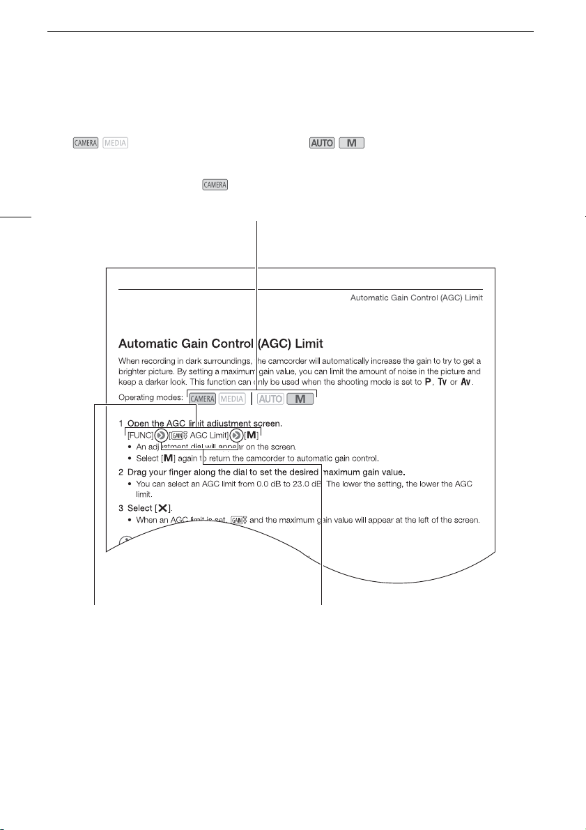
Brackets [ ] are used to
refer to onscreen buttons
and menu options you will
select and to other
onscreen messages and
displays.
These icons indicate the camcorder’s operating mode and whether a function is available in that
mode.
: Indicates whether the
camcorder is in shooting (CAMERA) or
playback (MEDIA) mode. In this example, the
function is available only in mode. For
details, refer to
Turning the Camcorder On
and Off
(A 23).
: Indicates the camera mode. For
details, refer to
Setting the Camera Mode
(A 24).
The > arrow is used to abbreviate menu
selections. For details on how to use the
menus, refer to
Using the Menus
(A 27).
For a summary of available menu options
and settings, refer to the appendix
Menu
Options
(A 102).
8
Page 9
Supplied Accessories
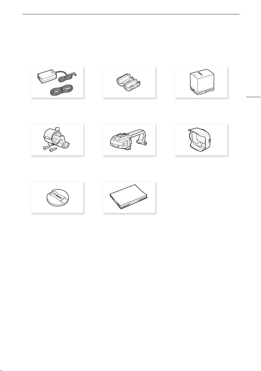
The following accessories are supplied with the camcorder:
Supplied Accessories
9
CA-570 Compact Power Adapter
(incl. power cord)
Microphone holder unit
(incl. screws)
Lens cap Quick Guide
Ferrite core BP-820 Battery Pack
Handle unit (incl. screws) Lens hood with lens barrier
Page 10
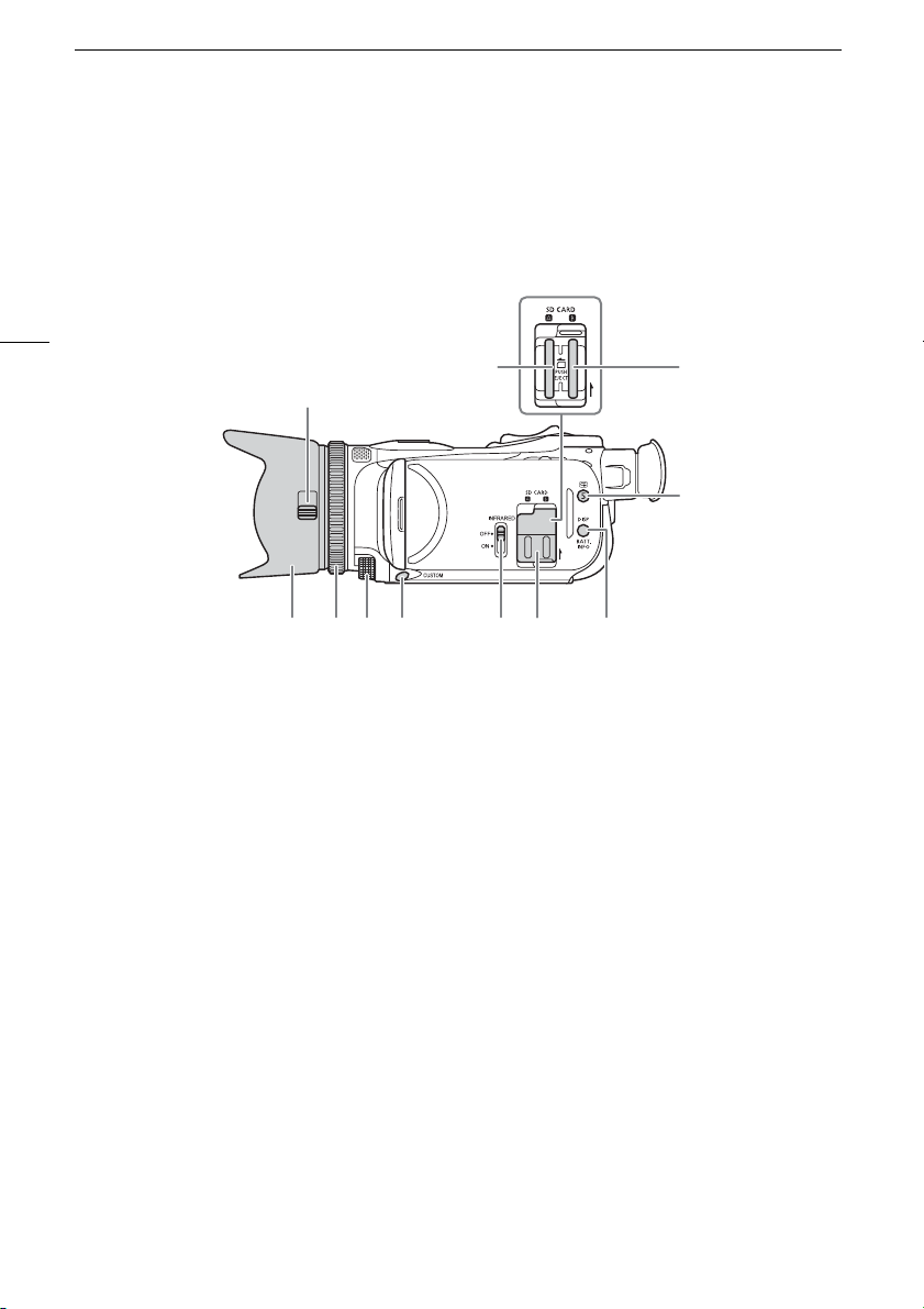
Names of Parts
32
4
119108765
1
Left side view
Names of Parts
10
1 Lens barrier switch (A 34)
2SD card slot 2 (A 30)
3SD card slot 3 (A 30)
4 u (review recording) button (A 36)/
5 Lens hood (A 19)
6 Focus/Zoom ring (A 52, 57)
7 CUSTOM (customizable) dial (A 84)
Assignable button 5 (A 85)
8 CUSTOM (customizable) button
(A 84)
9 INFRARED switch (A 80)
10 SD card compartment cover
11 DISP (onscreen display) button
(A 79)/BATT. INFO (battery
information) button (A 17)
Page 11

Names of Parts
26
7
3
4
5
9
1
8
Right side view
11
1 Built-in speaker (A 91)
2MIC terminal (A 68)
3 HDMI OUT terminal (A 96, 97)
4 REMOTE terminal (A 81)
For connecting commercially
available remote controllers.
5 s SDI OUT terminal (A 97)
6 × (headphones) terminal (A 76)
7USB terminal (A 82)
8DC IN terminal (A 15)
9 Grip belt (A 21)
Page 12
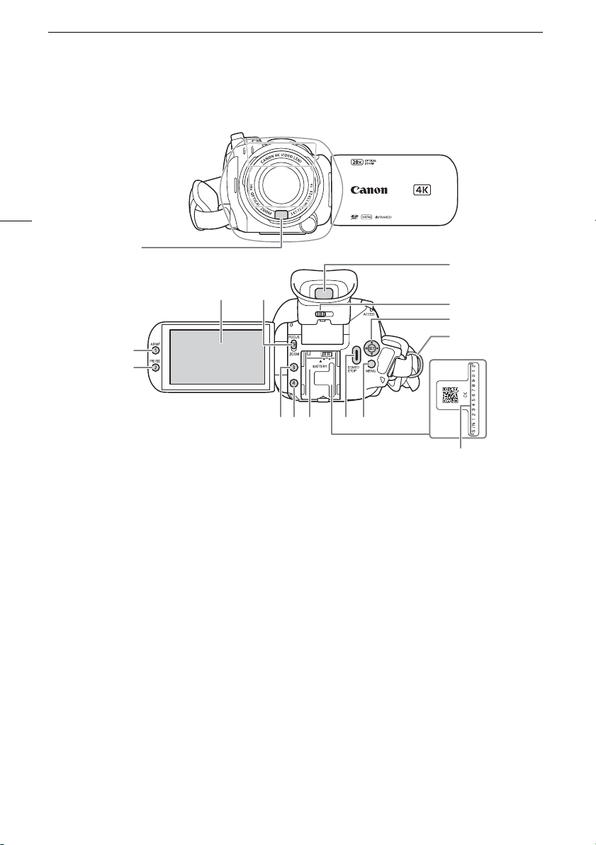
Names of Parts
1
45
6
7
8
9
14
15
13121110
3
2
Front view
Back view
12
1 Instant AF sensor (A 60, 126)
2 AF/MF button (A 57)/
Assignable button 1 (A 85)
3 PRE REC (pre-recording) button
(A 78)/
Assignable button 2 (A 85)
4 LCD touch screen (A 19)
5 Focus/Zoom ring switch (A 52, 57)
6Viewfinder (A 20)
7 Dioptric adjustment lever (A 20)
8 Joystick/SET button (A 24)
9 Strap mount (A 21)
10 Assignable button 3 (A 85)
11 Assignable button 4 (A 85)
12 Battery attachment unit (A 15)
13 START/STOP button (A 34)
14 MENU button (A 27)
15 Serial number
Page 13
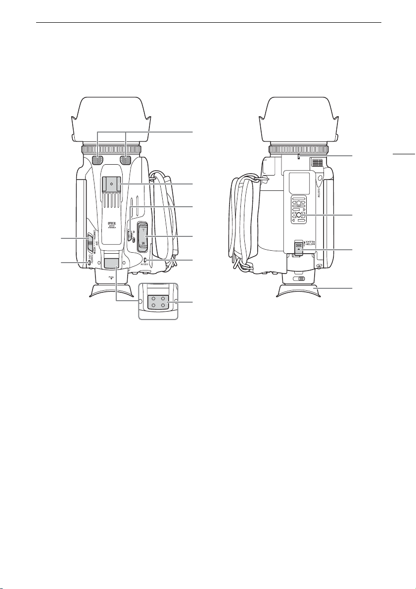
Names of Parts
Top view Bottom view
3
13
9
4
5
1
2
6
7
8
1 Power switch (A 23)
2 POWER / CHG (battery charging)
indicator (A 15)
8 Handle unit mount (A 18)
9 Lens hood mount index mark
10 Tripod socket
3 Built-in stereo microphone
(A 68)
4 Accessory shoe
5 Camera mode switch (A 24)
6 Grip zoom rocker (A 53)
11 BATTERY RELEASE switch (A 16)
12 Eye cup (A 20)
7 ACCESS indicator (A 34)
10
11
12
For mounting the camcorder on a
tripod with a mounting screw 6.5 mm
(0.26 in.) or shorter.
Page 14
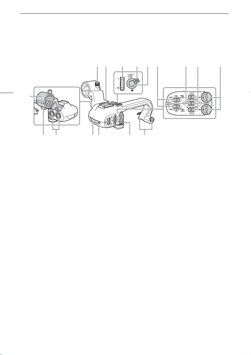
Names of Parts
23 4 5 6 7 8 9 10
161514131211
1
Handle unit
14
1 Microphone holder unit (A 68)
2 Microphone lock screw (A 68)
3 Accessory shoe
4 Handle zoom rocker (A 53)
5START/STOP lock (C) lever (A 35)
6 START/STOP button (A 34)
7 Sensitivity selection switches for
INPUT 1 and INPUT 2 (A 71)
8 INPUT terminal ON/OFF switch
(A 73)
9 Audio level switches for CH1 and
CH2 (A 72)
10 Audio level dials for CH1 and CH2
(A 72)
11 Microphone cable clamp (A 70)
12 INPUT 1 and INPUT 2 terminals
(collectively referred to as "INPUT
terminals") (A 71)
13 Infrared light (A 80)
14 Tally lamp (A 34)
15 Handle unit front screw (A 18)
16 Handle unit rear screws (A 18)
Page 15
Attaching the Ferrite Core
DC IN terminal
Preparations
2
Preparations
Attaching the Ferrite Core
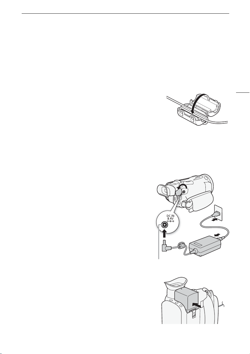
Attach the enclosed ferrite core before you connect the compact power adapter to the camcorder.
Attaching the ferrite core to the compact power adapter cable is necessary to suppress RF
interference.
Attach the ferrite core to the cable about 6 cm (2.4 in.) from the
DC plug (the plug to be connected to the DC IN terminal).
Pass the cable through the center of the core and wrap it around the
core (as shown in the illustration), then close the unit until it clicks shut.
Charging the Battery Pack
The camcorder can be powered with a battery pack or directly using the supplied CA-570 Compact
Power Adapter.
1 Connect the compact power adapter to the
camcorder and plug the power cord into a power
outlet.
15
2 Attach the battery pack to the camcorder.
• Press the battery pack softly into the battery attachment
unit and slide it forward until it clicks in place.
Page 16
Charging the Battery Pack
IMPORTANT
NOTES
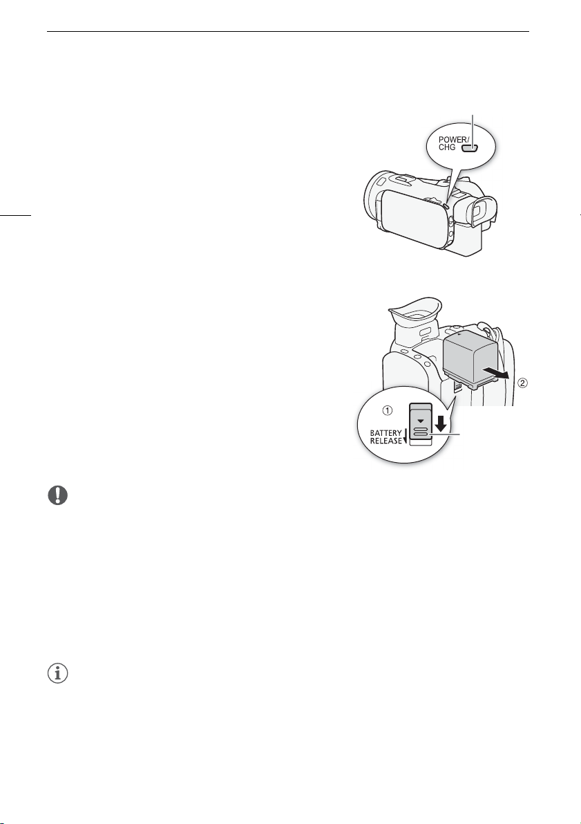
POWER/CHG (battery charging) indicator
BATTERY
RELEASE
switch
3 Charging will start when the camcorder is turned off.
• If the camcorder was on, the green POWER/CHG indicator
will go out when you turn off the camcorder. After a
moment, the POWER/CHG indicator will turn on in red
(battery pack charging). The red POWER/CHG indicator will
go out when the battery pack is fully charged.
16
• If the indicator flashes, refer to
Troubleshooting
To remove the battery pack
1 Slide the BATTERY RELEASE switch in the direction of the
arrow and hold it pressed down (
2 Slide the battery pack and then pull it out (
햲).
햳).
(A 118).
• Turn off the camcorder before connecting or disconnecting the compact power adapter. After you
turn off the camcorder, important data is updated on the SD card. Be sure to wait until the green
POWER/CHG indicator goes out.
• When using the compact power adapter, do not fix it permanently to one place as this may cause a
malfunction.
• Do not connect to the camcorder’s DC IN terminal or to the compact power adapter any electrical
equipment that is not expressly recommended for use with this camcorder.
• To prevent equipment breakdowns and excessive heating, do not connect the supplied compact
power adapter to voltage converters for overseas travels or special power sources such as those on
aircraft and ships, DC-AC inverters, etc.
• We recommend charging the battery pack in temperatures between 10 °C and 30 °C (50 °F and
86 °F). If either the ambient temperature or the battery pack’s temperature is outside the range of
approx. 0 °C to 40 °C (32 °F to 104 °F), charging will not start.
• The battery pack will be charged only when the camcorder is off.
• If the power supply was disconnected while charging a battery pack, make sure the POWER/CHG
indicator has gone out before restoring the power supply.
Page 17
Charging the Battery Pack
• If remaining battery time is an issue, you can power the camcorder using the compact power
adapter so the battery pack will not be consumed.
• Charged battery packs continue to discharge naturally. Therefore, charge them on the day of use, or
the day before, to ensure a full charge.
• The first time you use a battery pack, fully charge it and then use the camcorder until the battery
pack is completely depleted. Doing so will ensure that the remaining recording time will be displayed
accurately.
• We recommend that you prepare battery packs to last 2 to 3 times longer than you think you might
need.
• For handling precautions regarding the battery pack, refer to
Precautions
• For charging times and approximate usage times, refer to
(A 122).
Safety Instructions and Handling
Reference Tables
(A 134).
Checking the Remaining Battery Charge
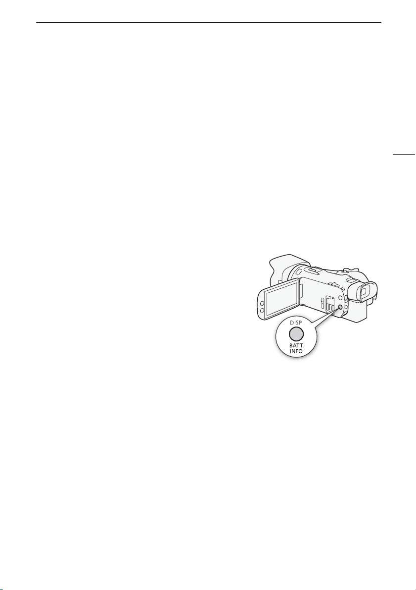
With the camcorder turned off, press the BATT. INFO button to display for about 5 seconds a screen
showing the approximate battery charge level. Note that if the battery charge is too low, the battery
information screen may not appear.
17
Page 18
Preparing the Camcorder
IMPORTANT
NOTES
Preparing the Camcorder
This section covers the basic preparations for the camcorder such as attaching the handle unit and
lens hood, and adjusting the viewfinder and LCD screen.
• Be careful not to drop the camcorder when attaching, removing or adjusting the various
18
accessories. Using a table or other stable surface is recommended.
Attaching the Microphone Holder Unit
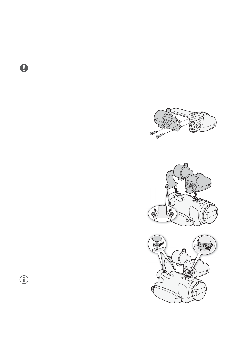
Use the supplied screws to attach the microphone holder unit to
the handle unit.
Attaching the Handle Unit
1 Slide the front of the handle unit into the accessory
shoe, as shown in the illustration. Then, slide the handle
unit forward all the way.
• Make sure the front and rear screws are raised when you
slide the handle unit.
2 Turn the front screw and two rear screws to secure the
handle unit.
• The camcorder is functional even if you remove the handle
unit. However, some audio options (A 68), the infrared light
(A 80) and tally lamp will not be available.
Page 19
Preparing the Camcorder
NOTES
NOTES
Subject can monitor the LCD screen
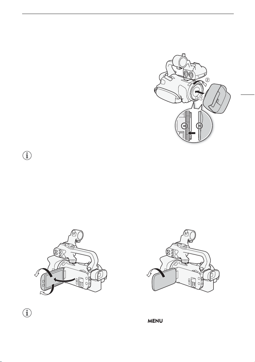
Using the Lens Hood
While recording, the supplied lens hood with lens barrier is
effective for reducing stray light that can be the cause of lens
flare and ghost images. Additionally, closing the lens barrier
can help prevent fingerprints and dirt accumulation on the
lens.
1 Remove the lens cap.
2 Align the mark on the lens hood with the lens hood
mount index mark on the bottom of the camcorder
(
햲), and then turn the lens hood clockwise until it
stops with a click
• Be careful not to deform the lens hood.
• Make sure that the lens hood is aligned with the thread.
• To remove the lens hood, turn it counterclockwise.
About the lens cap:
• Use the supplied lens cap when carrying the camcorder or storing it after use.
• Note that the lens cap and the lens hood with lens barrier cannot be used simultaneously.
(햳).
Adjusting the LCD Screen
Open the LCD panel 90 degrees.
• You can rotate the panel downward or toward the lens.
• Rotating the LCD toward the lens can be useful to allow the subject to monitor the LCD screen while
you use the viewfinder.
19
• You can adjust the brightness of the LCD screen with the > [£ Display Setup] > [LCD
Brightness] or [LCD Backlight] setting. Also, you can hold the DISP button pressed down for more
than 2 seconds to change the [LCD Backlight] setting between bright and normal or from dim to
normal.
Page 20
Preparing the Camcorder
NOTES
햲
햴
햳
햳
Dioptric
adjustment
lever
• Adjusting the brightness does not affect the brightness of recordings.
• Using a brighter setting will shorten the effective usage time of the battery pack.
• When the LCD panel is turned 180 degrees toward the subject, you can use the >
[£ Display Setup] > [LCD Mirror Image] setting to reverse the screen’s image horizontally,
showing a mirror image of the subject.
• For details about how to take care of the LCD screen, refer to
Cleaning
20
• About the LCD and viewfinder screens: The screens are produced using extremely high-precision
(A 126).
manufacturing techniques, with more than 99.99% of the pixels operating to specification. Very
rarely, pixels may misfire or may light up permanently as white dots. This has no effect on the
recorded image and does not constitute a malfunction.
Handling Precautions
(A 123),
Using the Viewfinder
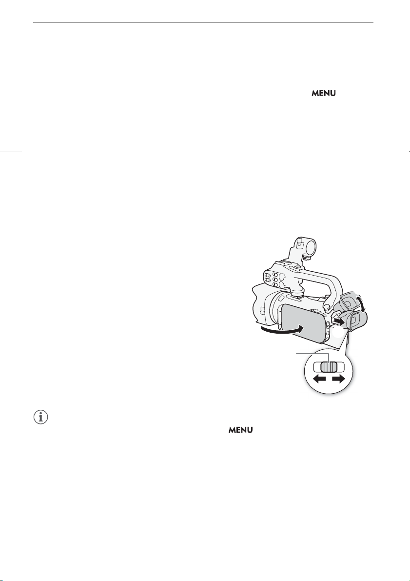
If it is difficult to use the LCD screen, you can use the viewfinder, which can be tilted 45 degrees
upward.
1 Use the power switch to turn on the camcorder.
(A 23).
2 Close the LCD panel (
3 Pull out the viewfinder and adjust the viewing angle
(
햳).
4 Adjust the viewfinder using the dioptric adjustment
lever (
햴).
햲).
• You can adjust the brightness of the viewfinder with the > [£ Display Setup] >
[Viewfinder Backlight] setting.
• Adjusting the brightness does not affect the brightness of recordings.
• Using a brighter setting will shorten the effective usage time of the battery pack.
• You cannot use the LCD screen and viewfinder simultaneously.
Page 21
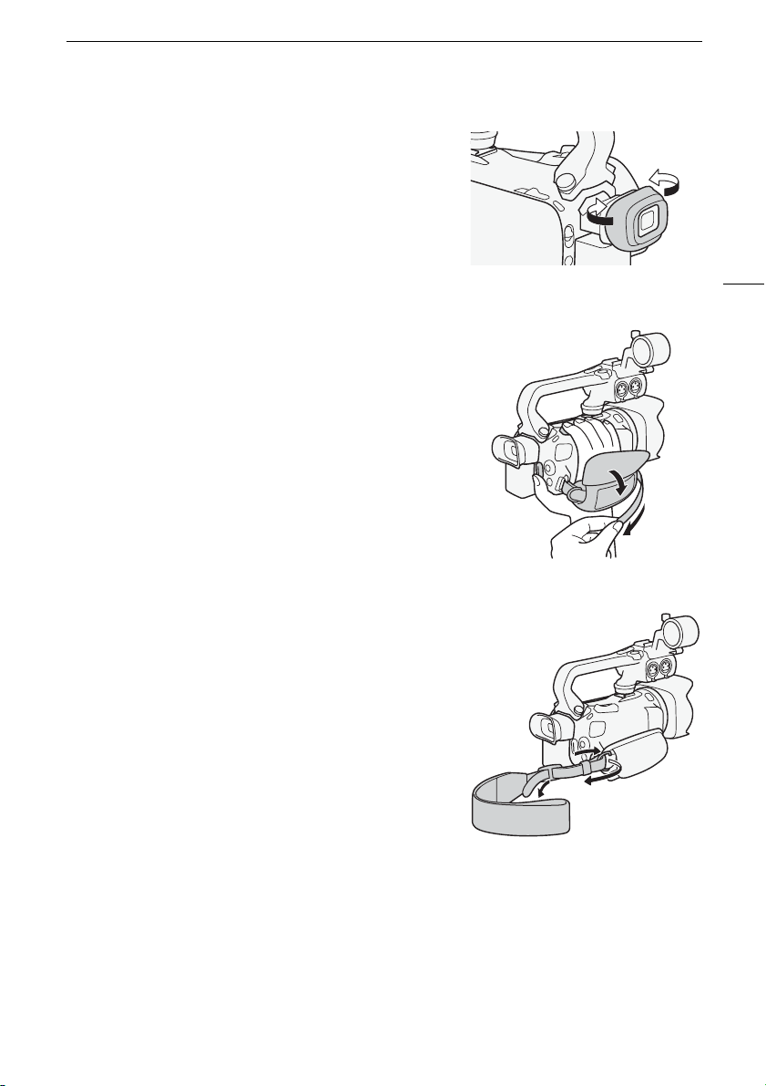
• Make sure you keep the eye cup attached when using the
camcorder.
If you wear glasses, you may find the viewfinder easier to
use if you flip back the outer edge of the eye cup toward the
camcorder body.
• For details about how to take care of the viewfinder, refer to
Handling Precautions
(A 123),
Cleaning
(A 126).
Grip Belt and Straps
Fasten the grip belt.
• Adjust the grip belt so that you can reach the grip zoom
rocker with your index finger, and the START/STOP button
with your thumb.
Preparing the Camcorder
21
Attaching an optional wrist strap
Attach the wrist strap to the strap mount on the grip belt,
adjust the length and fasten.
• You can use both for extra convenience and protection.
Page 22
Preparing the Camcorder
Attaching an optional shoulder strap
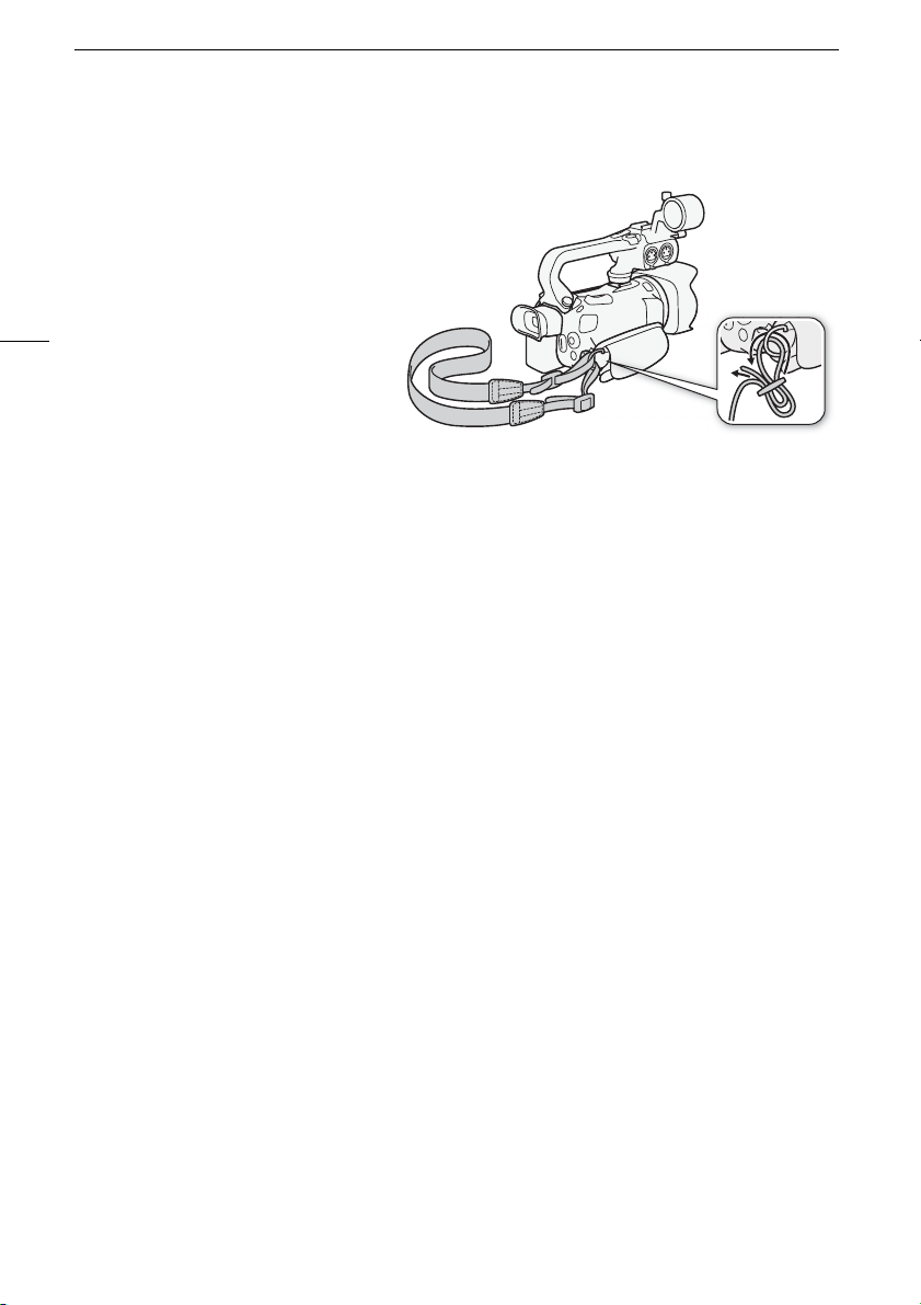
Pass the ends of the shoulder strap
through the strap mount on the grip belt
and adjust the length of the strap.
22
Page 23
Basic Operation of the Camcorder
NOTES
POWER/CHG indicator
mode mode
Basic Operation of the Camcorder
Turning the Camcorder On and Off
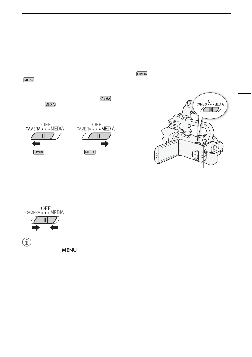
You can choose to turn the camcorder on in CAMERA ( ) mode for making recordings or MEDIA
( ) mode for playing back recordings. Select the mode using the power switch.
To turn on the camcorder
Set the power switch to CAMERA for mode (A 34) or
MEDIA for mode (A 88).
• The POWER/CHG indicator will illuminate in green.
To turn off the camcorder
Set the power switch to OFF.
• The POWER/CHG indicator will go out.
23
• You can use the > [B System Setup] > [POWER LED] setting to prevent the POWER
indicator from illuminating.
Page 24
Basic Operation of the Camcorder
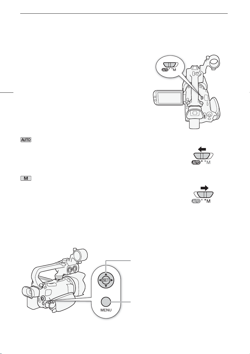
Joystick/SET button
When making a menu selection, push the joystick to
move the orange selection frame in the menu. Then,
press the joystick itself (in the manual, "press SET")
to select the menu item indicated by the orange
selection frame.
MENU button
Press the button to open the setup menus and then
press again to close the menu after adjusting
desired settings.
Setting the Camera Mode
When making recordings, you can change the camera mode
to match your shooting style.
24
(Auto) mode
Set the camera mode switch to N. With this mode, the camcorder takes
care of all the settings while you concentrate on recording (A 35). This
operating mode is suitable if you just prefer not to bother with detailed
camcorder settings.
(Manual) mode
Set the camera mode switch to n. With this mode, you can enjoy full access to
menus, settings and advanced functions.
Using the MENU Button and Joystick
You can navigate some of the camcorder’s menus and screens using the MENU button and joystick
instead of using the touch screen.
Page 25
First Time Settings
NOTES
First Time Settings
Setting the Date and Time
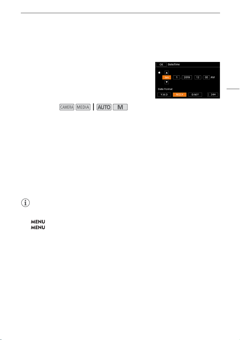
You will need to set the date and time of the camcorder before
you can start using it. The [Date/Time] screen will appear
automatically when the camcorder’s clock is not set.
Operating modes:
1 Use the power switch to turn on the camcorder.
• The [Date/Time] screen will appear.
2 Touch a field you want to change (year, month, day, hours or minutes).
• You can also push the joystick (ÏÐ) to move between the fields.
3Touch [Í] or [Î] to change the field as necessary.
• You can also push the joystick (ÍÎ) to change the field.
4 Set the correct date and time by changing all the fields in the same way.
5 Touch [Y.M.D], [M.D,Y] or [D.M.Y] to select the date format you prefer.
• In some screens, the date will be displayed in short form (numbers instead of month names or
only the day and month), but it will still follow the order you selected.
6 Touch [24H] to use 24-hour clock or leave it unselected to use 12-hour clock (AM/PM).
7 Touch [OK] to start the clock and close the setup screen.
25
• With the following settings, you can change the time zone, date and time also after the initial setup.
You can also change the date format and clock format (12 or 24 hours).
- > [B System Setup] > [Time Zone/DST]
- > [B System Setup] > [Date/Time]
• When you do not use the camcorder for about 3 months, the built-in rechargeable lithium battery
may discharge completely and the date and time setting may be lost. In such case, recharge the
built-in lithium battery (A 125) and set the time zone, date and time again.
• Using the optional GP-E2 GPS Receiver, you can have the camcorder adjust settings automatically
according to the UTC date/time information received from the GPS signal (A 82).
Page 26
First Time Settings
NOTES
Changing the Language
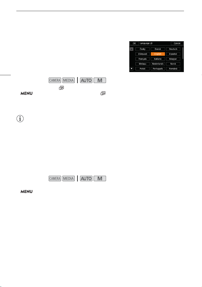
The default language of the camcorder is English. You can set
it to one of 27 languages.
Setup Menus
Refer to
the menu for this procedure.
(A 27) for details on how to navigate
26
Operating modes:
1 Open the [Language ] screen.
> [B ! System Setup] > [Language ]
2 Select the desired language and then select [OK].
3 Select [X] to close the menu.
• Some onscreen buttons, such as [ZOOM], [FUNC] and [MENU], will appear in English regardless of
the language selected.
Changing the Time Zone
Change the time zone to match your location. The default setting is New York. In addition, the
camcorder is able to retain the date and time of an additional location. This is convenient when you
travel so that you can set the camcorder to match the time of your home location or that of your travel
destination.
Setup Menus
Refer to
Operating modes:
(A 27) for details on how to navigate the menu for this procedure.
1 Open the [Time Zone/DST] screen.
> [B ! System Setup] > [Time Zone/DST]
2 Select ["] to set the home time zone, or [#] to set the time zone of your destination
when you are traveling.
3 Select [Ï] or [Ð] to set the desired time zone. If necessary, select [$] to adjust for
daylight saving time.
4 Select [X] to close the menu.
Page 27
Using the Menus
Using the Menus
The camcorder’s functions can be adjusted from the setup menus, accessed by pressing the MENU
button, or from the FUNC menu, accessed by touching or selecting the onscreen [FUNC] button. For
details about the available menu options and settings, refer to
Menu Options
(A 102).
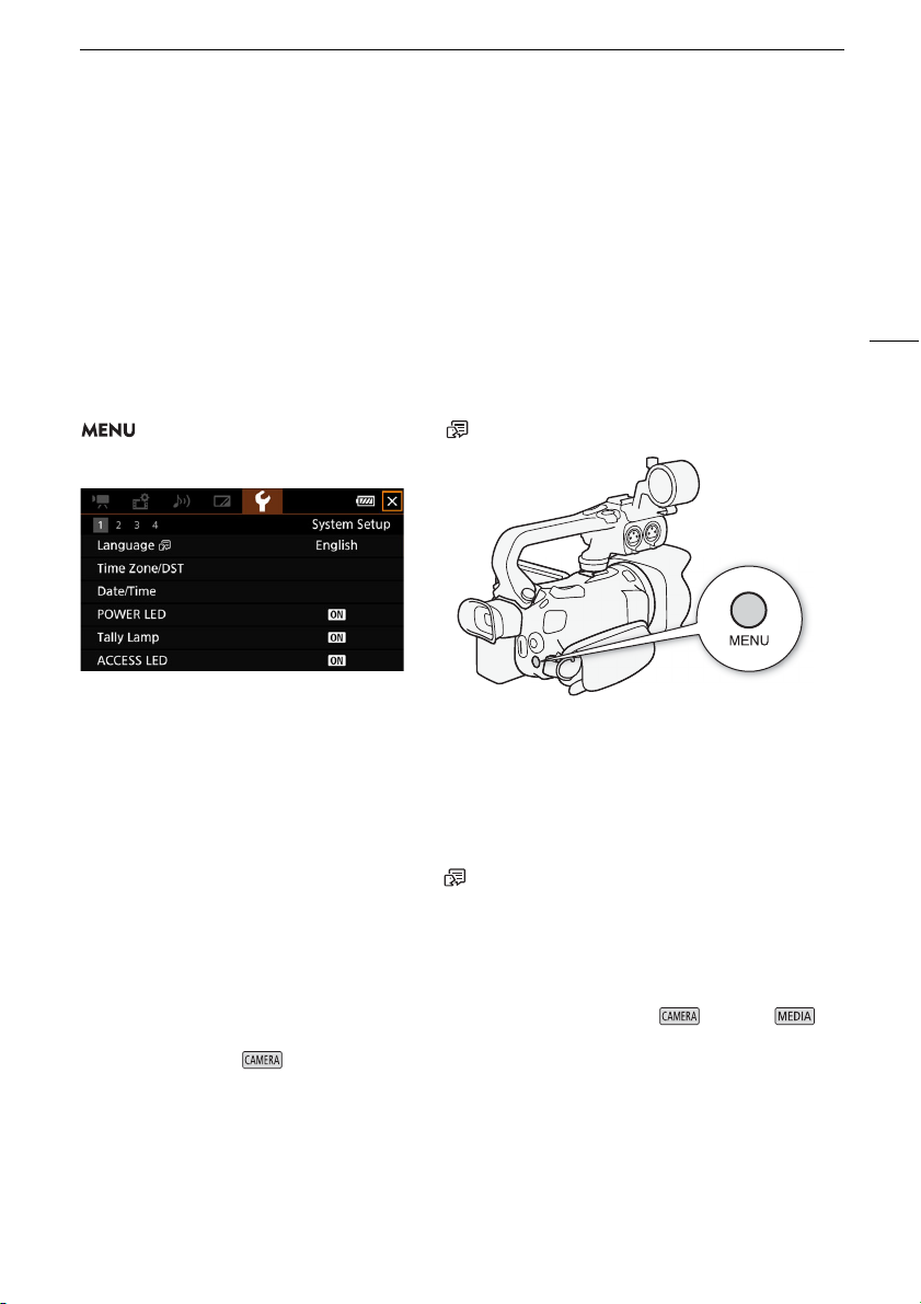
Setup Menus
Following is a step-by-step explanation of how to select a typical option from the setup menus. Some
menu items may require additional steps. Such operations will be explained in the respective section of
the manual.
For brevity's sake, references to menu settings throughout the manual may be abbreviated as follows:
> [B ! System Setup] > [Language ] > Desired option
To use the touch panel
1 Press the MENU button.
2 Touch the icon of the desired setup menu from the top row.
• In the example, the B icon, corresponding to the [System Setup] menu.
3 Touch the desired menu item ([Language ], in the example).
• If the desired menu item does not appear in the menu page displayed, drag your finger left/right
to scroll through other menu pages.
• For main procedures, the page number may be given in the manual (!, in the example). If you
know the page number, you can touch the number icon on the top left of the screen to open
directly the desired menu page.
• The page number may differ depending on whether the camcorder is in mode or
mode. Throughout the manual, procedures for functions that can be used in both modes give the
page number in mode.
4 Touch the desired setting option and then touch [X] to close the menu.
• You can touch [L] to return to the previous menu page.
27
Page 28
Using the Menus
NOTES
FUNC menu in mode
To use the joystick
1 Press the MENU button.
2 Push the joystick (Þ) to select the icon of the desired setup menu.
• In the example, the B icon, corresponding to the [System Setup] menu.
• If one of the icons in the top row is not selected when you open the menu, first push the joystick
Ý) to move the orange selection frame to one of the icons.
(
28
3 Push the joystick (Ý) to select the desired menu item ([Language ], in the example)
and then press SET.
• If the desired menu item does not appear in the menu page displayed, push the joystick (Þ)
to scroll through other menu pages.
• For main procedures, the page number may be given in the manual (!, in the example), making
it easier to find the desired menu page.
4 Push the joystick (Ý) to select the desired setting option and then press SET.
5 Press the MENU button to close the menu.
• You can push the joystick to highlight the [L] button and press SET to return to the previous
menu page. You can also highlight the [X] button and press SET to close the menu.
• Touching [X] or pressing the MENU button at any time closes the menu.
• Unavailable items may appear grayed out.
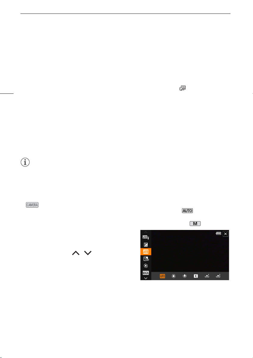
FUNC Menu
In mode, the FUNC menu offers a quick way to control various shooting related functions such
as white balance, exposure, focus, etc. Available functions are more limited in mode.
To use the touch panel
1 Touch [FUNC] on the shooting screen.
2 Touch the icon of the desired function on the
left column.
• If necessary, touch [ ]/[ ] to scroll up/down.
3 Touch the icon of the desired setting on the
bottom row.
4Touch [X] to close the FUNC menu or [L] to
return to the left column.
Page 29

Using the Menus
NOTES
To use the joystick
1 On the shooting screen, push the joystick to select [FUNC] and then press SET.
2 Push the joystick (Ý) to select the desired icon from the left column and then press SET.
3 Push the joystick (Þ) to select the desired icon from the bottom row and then press
SET.
• To select a value from an adjustment dial, first push the joystick (Î) to highlight the dial in orange
and then (Þ) to select the desired value.
4 Select [X] to close the FUNC menu or [L] to return to the left column.
• From the left column, push the joystick (Ð) to select the [X] icon and then press SET. From the
bottom row, push the joystick (Í) once and then (Þ) to select the desired icon.
• Depending on the selected function, other buttons, adjustment dials, and other controls may
appear on the screen. These are explained in the respective section of the manual.
29
Page 30
Using SD Cards
IMPORTANT
NOTES
Using SD Cards
The camcorder records clips and photos on commercially available Secure Digital (SD) cards1. The
camcorder has two SD card slots and you can use two SD cards (in the manual, "SD card A" and "SD
card B") to record on both simultaneously or to automatically switch to the other SD card when the SD
card in use is full (A 32).
Initialize SD cards (A 32) when you use them with this camcorder for the first time.
1
The SD card is used also to save menu settings files.
30
Compatible SD Cards
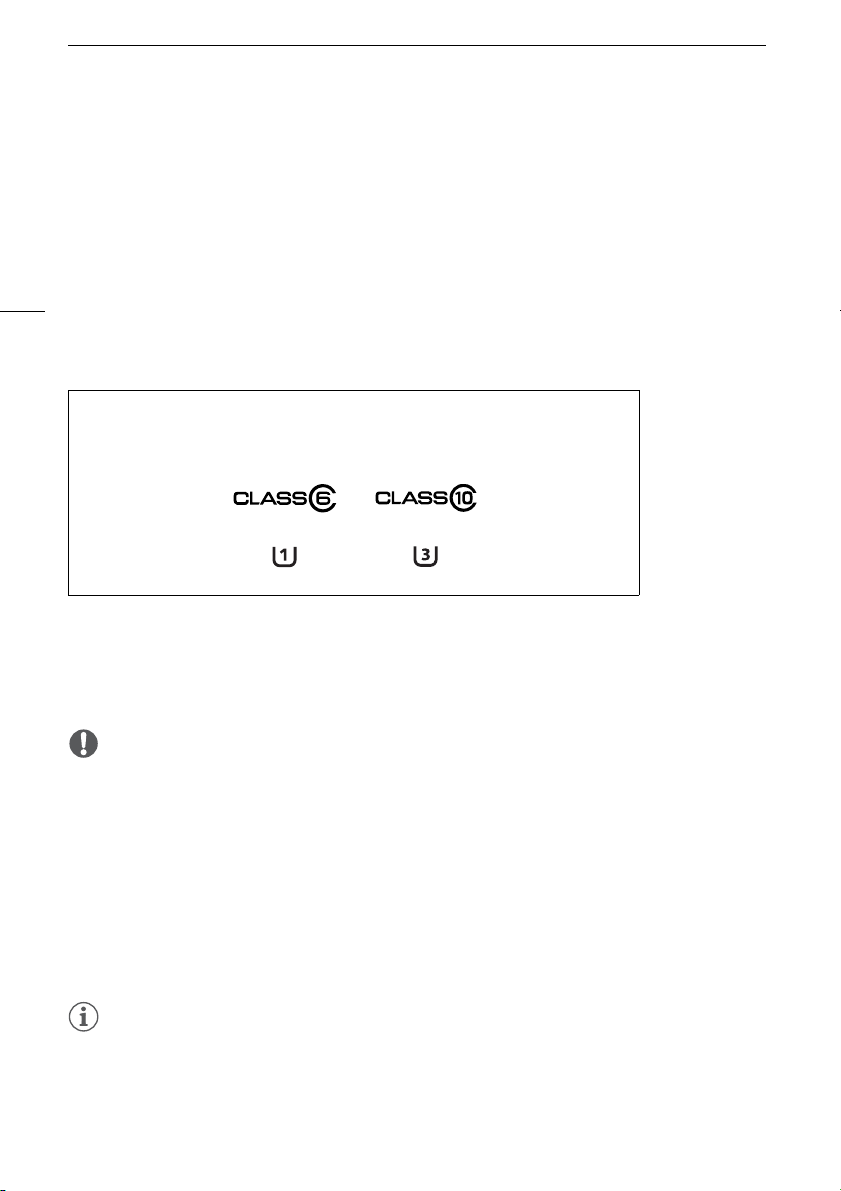
The following types of SD cards2 can be used with this camcorder. For the latest information about SD
cards tested for use with this camcorder, visit your local Canon website.
SD card type:
3
SD Speed Class
UHS Speed Class
2
As of February 2019, the clip recording function has been tested using SD cards made by Panasonic,
Toshiba and SanDisk.
3
UHS and SD Speed Class are standards that indicate the minimum guaranteed data transfer rate of SD
cards.
To record 4K clips with a resolution of 3840x2160 (A 37) or using slow & fast motion recording
(A 38), we recommend using SD cards rated UHS Speed Class U3.
• After repeatedly recording, deleting and editing clips (if the SD card is fragmented), you may notice
slower writing speeds to the card and recording may even stop. In such case, save your recordings
and initialize the card with the camcorder. Be sure to initialize SD cards especially before shooting
important scenes.
• About SDXC cards: You can use SDXC cards with this camcorder but SDXC cards are initialized by
the camcorder using the exFAT file system.
- When using exFAT-formatted cards with other devices (digital recorders, card readers, etc.), make
sure that the external device is compatible with exFAT. For more information on compatibility,
contact the computer, operating system or card manufacturer.
- If you use exFAT-formatted cards with a computer OS that is not exFAT-compatible, you may be
prompted to format the card. In such case, cancel the operation to prevent data loss.
:
3
:
./ 0
SD cards SDHC cards SDXC cards
Speed Class U1 Speed Class U3
• Proper operation cannot be guaranteed for all SD cards.
Page 31
Using SD Cards
IMPORTANT
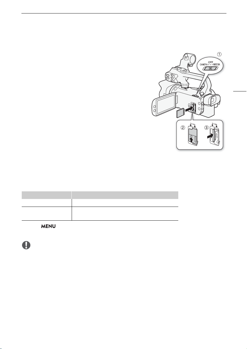
Inserting and Removing an SD Card
1 Turn off the camcorder (햲).
• Make sure the POWER/CHG indicator is off.
2 Open the SD card compartment cover (햳).
3 Insert the SD card straight, with the label facing the
front of the camcorder, all the way into one of the SD
card slots (
• You can also use two cards, one in each SD card slot.
4 Close the SD card compartment cover.
• Do not force the cover closed if the SD card is not correctly
inserted.
To remove the SD card
1 Make sure the ACCESS indicator is off.
2 Push the SD card once to release it. When the SD card springs out, pull it all the way out.
ACCESS (SD card access) indicator
SD card access indicator SD card status
Red (on or flashing) Accessing the SD card(s).
Off
If you set > [B System Setup] > [ACCESS LED] to [j Off], the ACCESS indicator will not
illuminate.
햴).
Neither SD card is being accessed or no SD cards are
inserted in the camcorder.
31
• Turn off the camcorder before inserting or removing an SD card. Inserting or removing a card with
the camcorder on may result in permanent data loss.
• SD cards have front and back sides that are not interchangeable. Inserting an SD card facing the
wrong direction can cause a malfunction of the camcorder. Be sure to insert the SD card as
described in step 3.
Page 32
Using SD Cards
IMPORTANT
Initializing an SD Card
Initialize SD cards when you use them with this camcorder for the first time. You can also initialize a
card to permanently delete all the recordings it contains.
Operating modes:
1 Select [Initialize] for the desired SD card.
32
> [3 " Recording Setup] > [Initialize 8] > [6 Mem. Card A] or
[7 Mem. Card B] > [Initialize]
2 Select [Yes].
3 When the confirmation message appears, select [OK] and then select [X].
• Initializing an SD card will permanently erase all recordings. Lost data cannot be recovered. Make
sure you save important recordings in advance (A 100).
• Depending on the SD card, the initialization may take up to a few minutes.
Selecting the SD Card for Recordings
You can select the SD card on which clips and photos will be recorded.
Operating modes:
1 Select [Recording Media].
> [3 ! Recording Setup] > [Recording Media]
2 Select the desired SD card ([6 Mem. Card A] or [7 Mem. Card B]) for recording clips
([v Rec Media for Movies]) and/or photos ([{ Rec Media for Photos]).
3 Select [X].
• After closing the menu, the icon of the SD card selected for recording clips will appear on the
screen.
Dual Recording and Relay Recording
The camcorder features two convenient recording methods that can be used when both card slots
contain an SD card: dual recording and relay recording.
Dual recording: This function records the same clip simultaneously to both SD cards, which is a
convenient way to make a backup copy of your recordings while you record.
Relay recording: This function allows you to continue recording on the other SD card without
interruption when the SD card you are using becomes full.
Operating modes:
1 Select [Dual/Relay Recording].
> [3 ! Recording Setup] > [Dual/Relay Recording]
Page 33
Using SD Cards
NOTES
NOTES
2 Select [4 Dual Recording] or [ Relay Recording] (or [ Relay Recording]) and then
select [X].
• When dual recording is activated, the status of both SD cards will appear at the top right of the
screen.
• Select [Standard Recording] to not use either function.
• Relay recording is available from SD card slot A to SD card slot B, and vice versa, but the switch will
be performed only once.
• After saving to a computer relay clips that were originally recorded on different SD cards, you can
use the MP4 Join Tool to join the files and save them as a single clip (A 100).
• If an SD card becomes full during dual recording, recording on both cards will stop. On the other
hand, if an error occurs with one of the SD cards, recording will continue on the other card.
• Dual recording cannot be used together with slow & fast motion recording.
Recovering Clips
Some actions, such as suddenly turning off the camcorder or removing the SD card while data is
being recorded, can cause data errors in the recorded clip. You may be able to recover clips with
corrupted data with the following procedure.
Operating modes:
1 Open the index screen with the clip you wish to recover (A 88).
2 Select the corrupted clip (a clip with the icon instead of a thumbnail image).
3 When prompted to recover the data, select [Yes].
• The camcorder will attempt to recover the corrupted data.
4 When the confirmation message appears, select [OK].
• In the index screen, recovered clips appear with a special playback icon instead of the usual
thumbnail.
• This procedure may delete clips shorter than 0.5 seconds in length.
• In some cases, it may not be possible to recover the data. This is more likely when the file system is
corrupted or the SD card is physically damaged.
• Only clips recorded with this camcorder can be recovered. Photos cannot be recovered.
33
Page 34
Recording Clips and Photos
[PHOTO]
Lens barrier
switch
POWER/CHG
indicator
ACCESS indicator
Recording
3
Recording
Recording Clips and Photos
This section explains the basics of recording clips* and photos. For details on recording audio, refer to
Recording Audio
Before making important recordings for the first time, make test recordings using the video
34
configuration(s) you plan to use to check that the camcorder operates correctly. Should the camcorder
fail to operate correctly, refer to
* “Clip” refers to a single movie unit recorded with a single recording operation.
Basic Recording
When you use mode to shoot video and take photos, the camcorder will automatically adjust
various settings for you. In mode, you can manually adjust the focus, exposure and many other
settings according to your needs and preferences.
Operating modes:
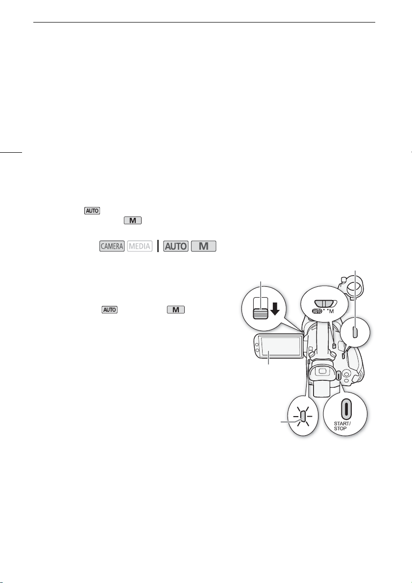
1 Open the lens barrier.
• Set the lens barrier switch to OPEN.
2 Set the camera mode switch to the desired
position.
•Set it to N ( mode) or n ( mode),
according to how you want to use the camcorder.
3 Set the power switch to CAMERA.
• The POWER/CHG indicator will illuminate in green.
(A 68).
Troubleshooting
(A 116).
To record video
Press the START/STOP button to begin recording.
• During recording, Ü will appear on the screen.
Additionally, if the handle unit is attached to the
camcorder, the tally lamp will illuminate.
• The ACCESS indicator will flash from time to time while
the clip is being recorded.
• Press the START/STOP button again to pause the
recording. Ü will change to Ñ and the clip will be
recorded on the SD card selected for recording clips. The camcorder will enter record standby
mode. The tally lamp will also go out.
• You can also press the START/STOP button on the handle unit.
To take photos
During record standby mode, touch [PHOTO].
• In the lower center of the screen, a green icon (g) will appear. Also, in the upper right of the screen,
{Ð will appear with the icon of the SD card selected for recording photos. The ACCESS indicator
will illuminate momentarily as the photo is being recorded.
Page 35
Recording Clips and Photos
IMPORTANT
NOTES
When you have finished recording
1 Set the lens barrier switch to CLOSED to close the lens barrier.
2 Make sure that the ACCESS indicator is off.
3 Set the power switch to OFF.
4 Close the LCD panel and return the viewfinder to its retracted position.
• Be sure to save your recordings regularly (A 100), especially after making important recordings.
Canon shall not be liable for any loss or corruption of data.
• The START/STOP button on the handle unit has a lock lever to prevent accidental operation. Set the
lock lever to C in cases such as when you do not want a recording inadvertently paused or do not
plan to use this START/STOP button. Return the lever to its previous position to enable use of the
START/STOP button again.
• You can set > [3 Recording Setup] > [Rec Command] and [HDMI Time Code] to
[i On] to use the camcorder’s START/STOP button to control also the recording operation of a
compatible external recorder connected to the SDI OUT terminal (s only) or HDMI OUT
terminal.
• The maximum continuous recording time of a single clip is 6 hours. After that, a new clip will be
created automatically and recording will continue as a separate clip.
• About mode: When the camcorder is in mode, it will automatically adjust settings such
as focus, exposure (aperture, shutter speed and gain) and white balance, depending on the scene
being shot. Additionally, when a subject's face is detected, the camcorder will automatically keep
the subject in focus and optimize the exposure.
• A video recording will be saved as separate clips in the following cases:
- When the camcorder switches to the other SD card while recording video due to the relay
recording function (A 32).
- The video (stream) file in the clip will be split approximately every 4 GB. Playback with the
camcorder will be continuous.
After saving the separate split clips to a computer, you can use the MP4 Join Tool to join the files
and save them as a single clip (A 100).
• Photos are recorded as JPG files. The camcorder can take photos during record standby mode.
• Photos cannot be recorded when pre-recording is activated.
• When recording in bright places, it may be difficult to use the LCD screen. In such case, use the
viewfinder or adjust the brightness of the screen (A 108).
• When you need to record for a long time with the camcorder set on a tripod, you can close the LCD
panel and use only the viewfinder in order to save power when using a battery pack (A 20).
35
Page 36
Recording Clips and Photos
Reviewing the Latest Clip Recorded
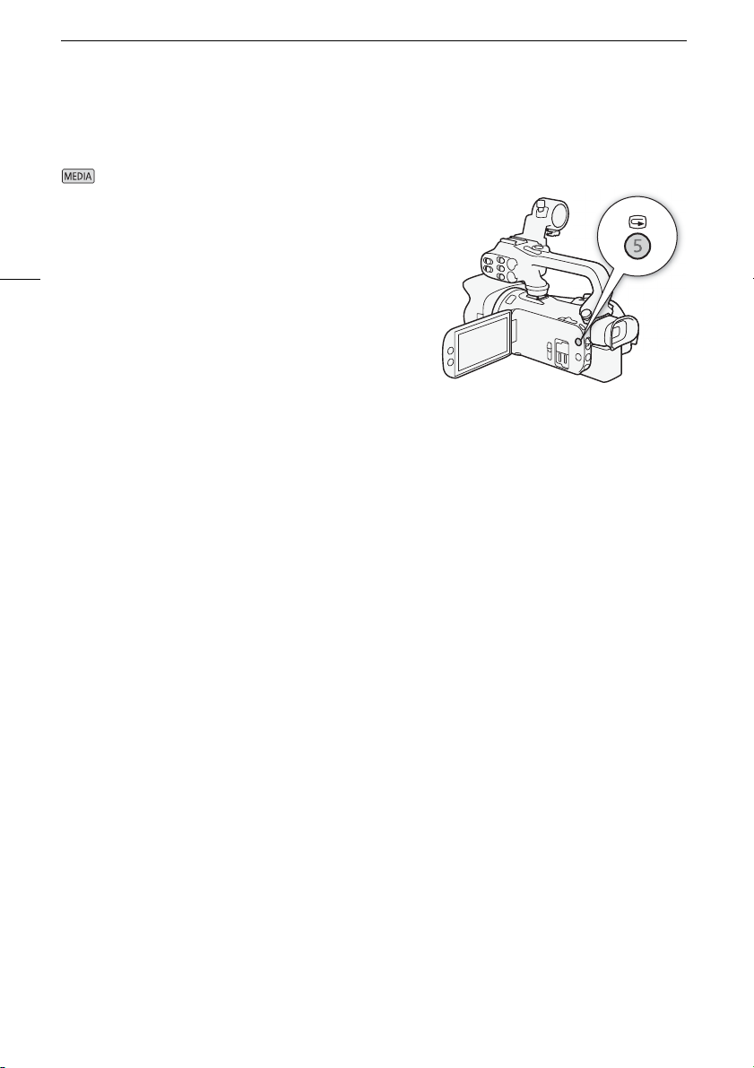
You can review the last 4 seconds of the last clip recorded with the camcorder without switching to
mode. While reviewing the clip, there will be no sound from the built-in speaker.
1 Record a clip.
2 After you finish recording a clip, press the u
button.
36
Page 37
Video Configuration: Resolution, Bit Rate and Frame Rate
NOTES
Video Configuration: Resolution, Bit Rate and Frame Rate
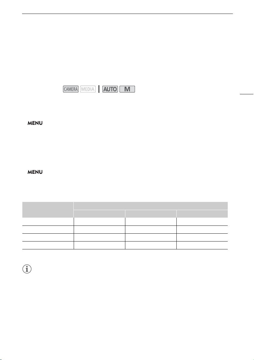
With the following procedures you can set the video configuration used for recording clips. Select the
combination of resolution/bit rate and frame rate settings that best matches your creative needs. The
color sampling will be YCbCr 4:2:0, 8 bit. Available options for some settings may change depending
on previous selections for other settings. See the table following the procedures for a summary.
For details on recording audio, refer to
Operating modes:
Selecting the Resolution and Bit Rate
1 Select [¸ Resolution].
> [3 ! Recording Setup] > [¸ Resolution]
2 Select the desired option and then select [X].
• The selected resolution and bit rate will appear at the right of the screen.
Selecting the Frame Rate
1 Select [¸ Frame Rate].
> [3 ! Recording Setup] > [¸ Frame Rate]
2 Select the desired option and then select [X].
• The icon of the selected frame rate will appear at the right of the screen.
Available video configuration settings
Resolution (Bit rate*)
3840x2160 (150 Mbps) — ● ●
1920x1080 (35 Mbps) ● ● ●
1920x1080 (17 Mbps) ● ● ●
1280x720 (8 Mbps) ● — —
Recording Audio
59.94P 29.97P 23.98P
(A 68).
Frame rate
37
* The camcorder uses a variable bit rate (VBR).
• For details on approximate recording times, refer to
Approximate recording times
(A 134).
Page 38
Slow & Fast Motion Recording
NOTES
Slow & Fast Motion Recording
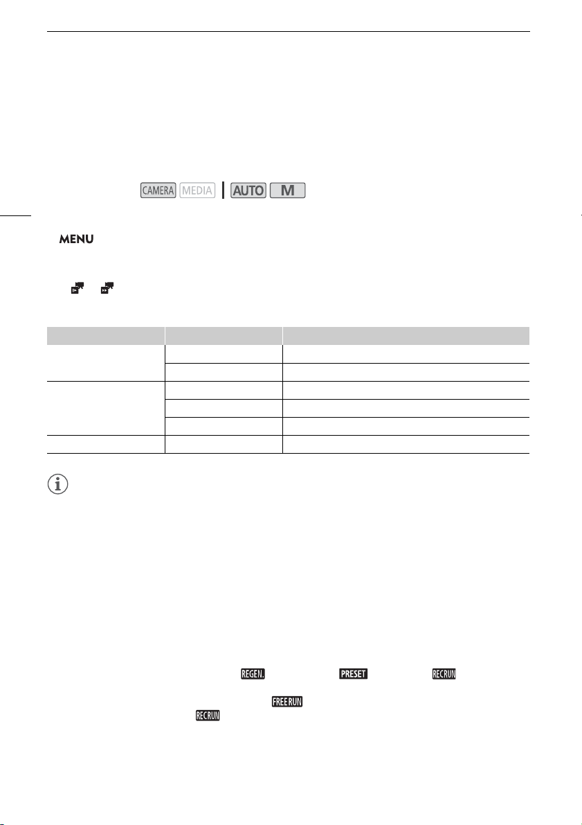
You can record clips that have a slow motion or fast motion effect during playback, simply by selecting
the desired slow/fast motion rate. Available slow/fast motion rates will vary depending on the
resolution and frame rate currently selected. Sound is not recorded when slow & fast motion recording
is activated.
Operating modes:
38
1 Select [Slow & Fast Motion].
> [3 ! Recording Setup] > [Slow & Fast Motion]
2 Select the desired slow & fast motion rate and then select [X].
• Select [j] to turn off slow & fast motion recording.
• or and the selected rate will appear on the right of the screen.
Available slow/fast motion rates
Resolution Frame rate Available slow/fast motion rates
3840x216029.97P x2, x4, x10, x20, x60, x120, x600, x1200
23.98P x0.8
1920x1080 59.94P x2, x4, x10, x20, x60, x120, x600, x1200
29.97P x0.5
23.98P x0.4, x0.8
1280x720 59.94P x2, x4, x10, x20, x60, x120, x600, x1200
• Slow & fast motion recording cannot be used together with the following functions.
- Dual recording
- Relay recording
• The maximum continuous recording time of a single clip using slow motion recording is the
equivalent of 6 hours of playback time, at which point, recording will stop. Consequently, it differs
depending on the slow motion rate used. For example, when the [x0.5] rate is selected, the
maximum continuous recording time will be 3 hours (which, played back at x0.5 slow motion, equal
6 hours of playback time). Conversely, fast motion recording will not stop in such a way.
• Changing the video configuration will deactivate slow & fast motion recording.
• While slow & fast motion recording is activated, the recording command signal will not be output
from the SDI OUT terminal (s only) or HDMI OUT terminal.
• About the time code when slow & fast motion recording is activated:
- The time code mode can be set to [ Regen.], or to [ Preset] with [ Rec Run]
running mode.
- If the time code running mode was set to [ Free Run], the time code running mode will be
changed automatically to [ Rec Run] when slow & fast motion recording is activated.
- When slow & fast motion recording is turned off, the time code running mode will return to its
previous setting.
- The time code signal cannot be output from the SDI OUT terminal (s only) or HDMI OUT
terminal.
- Pre-recording
- Color bars
Page 39
Shooting Modes
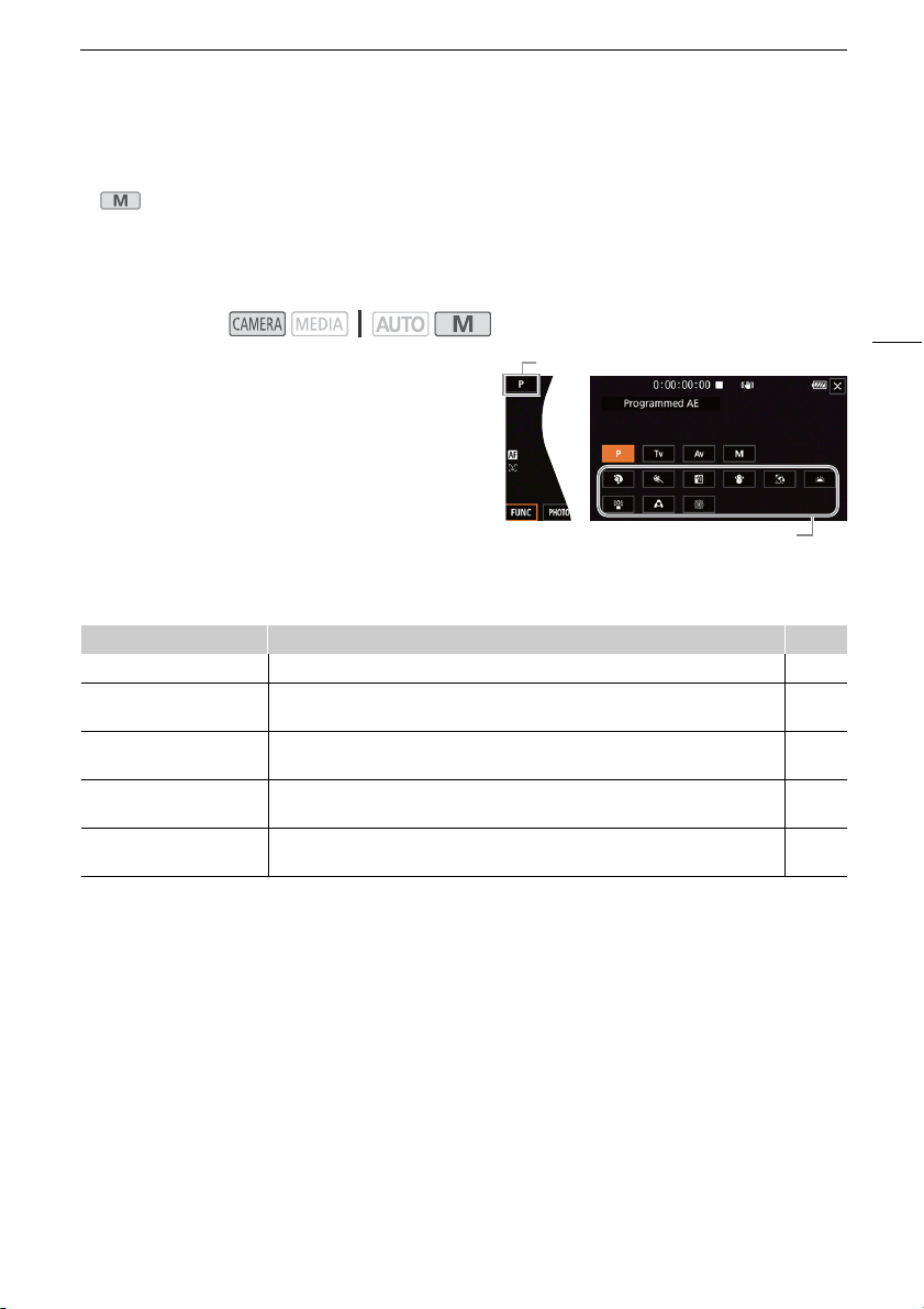
Shooting mode button
Special Scene modes
Shooting Modes
In mode, the camcorder offers a number of shooting modes that give you varying degrees of
control over the camcorder’s settings. Select the shooting mode most appropriate to your needs or
creative vision and adjust manually those settings you wish to control, letting the camcorder take care
of the rest.
Shooting modes cannot be used when infrared recording is activated.
Operating modes:
1 Select the shooting mode button.
2 Select the desired shooting mode and then
select [X].
• The shooting mode button will show the selected
mode's icon.
Available shooting modes
For details on shooting modes other than Special Scene modes, refer to Exposure Adjustment
(A 42).
Shooting mode Description A
’ (Programmed AE) The camcorder automatically sets the shutter speed, aperture and gain. 43
‚ (Shutter Priority AE) You manually set the shutter speed while the camcorder automatically adjusts
the aperture and gain.
“ (Aperture Priority AE) You manually set the aperture and ND filter while the camcorder automatically
adjusts the shutter speed and gain.
n (Manual Exposure) You manually set the shutter speed, aperture and gain, giving you full control
over the exposure.
Special Scene modes These modes offer preset combinations of settings optimized for specific
situations.
43
43
42
40
39
Page 40
Shooting Modes
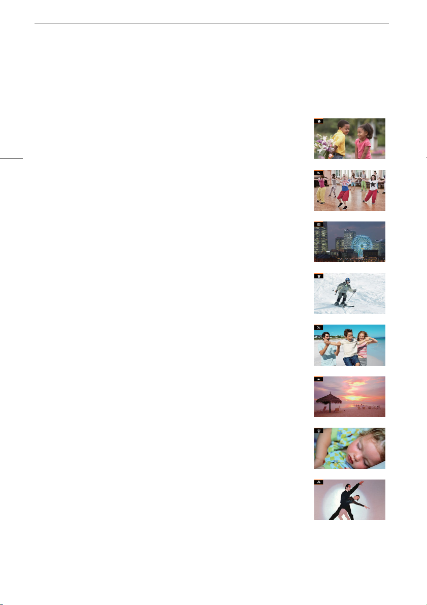
Special Scene Modes
Using a Special Scene mode can be an easy and convenient alternative to adjusting detailed exposure
settings.
[HPortrait] The camcorder uses a large aperture, to achieve a sharp focus
on the subject while blurring the background.
40
[ûSports] To record sports scenes, such as sporting events or dance
scenes.
[Q Night Scene] To record nightscapes with lower noise.
[K Snow] To record in bright ski resorts without the subject being
underexposed.
[L Beach] To record on a sunny beach without the subject being
underexposed.
[M Sunset] To record sunsets in vibrant colors.
[R Low Light] To record in low-light situations.
[S Spotlight] To record spotlit scenes.
Page 41

NOTES
[T Fireworks] To record fireworks.
Shooting Modes
•[H Portrait]/[û Sports]/[K Snow]/[L Beach]: The picture may not appear smooth during
playback.
•[H Portrait]: The blur effect of the background increases the more you zoom in (S).
•[K Snow]/[L Beach]: The subject may become overexposed on cloudy days or in shaded places.
Check the image on the screen.
•[R Low Light]:
- Moving subjects may leave a trailing afterimage.
- Picture quality may not be as good as in other modes.
- White points may appear on the screen.
- Autofocus may not work as well as in other modes. In such case, adjust the focus manually.
•[R Low Light]/[T Fireworks]: To avoid camcorder blur (blur due to the camcorder moving) we
recommend using a tripod.
41
Page 42
Exposure Adjustment
Exposure Adjustment
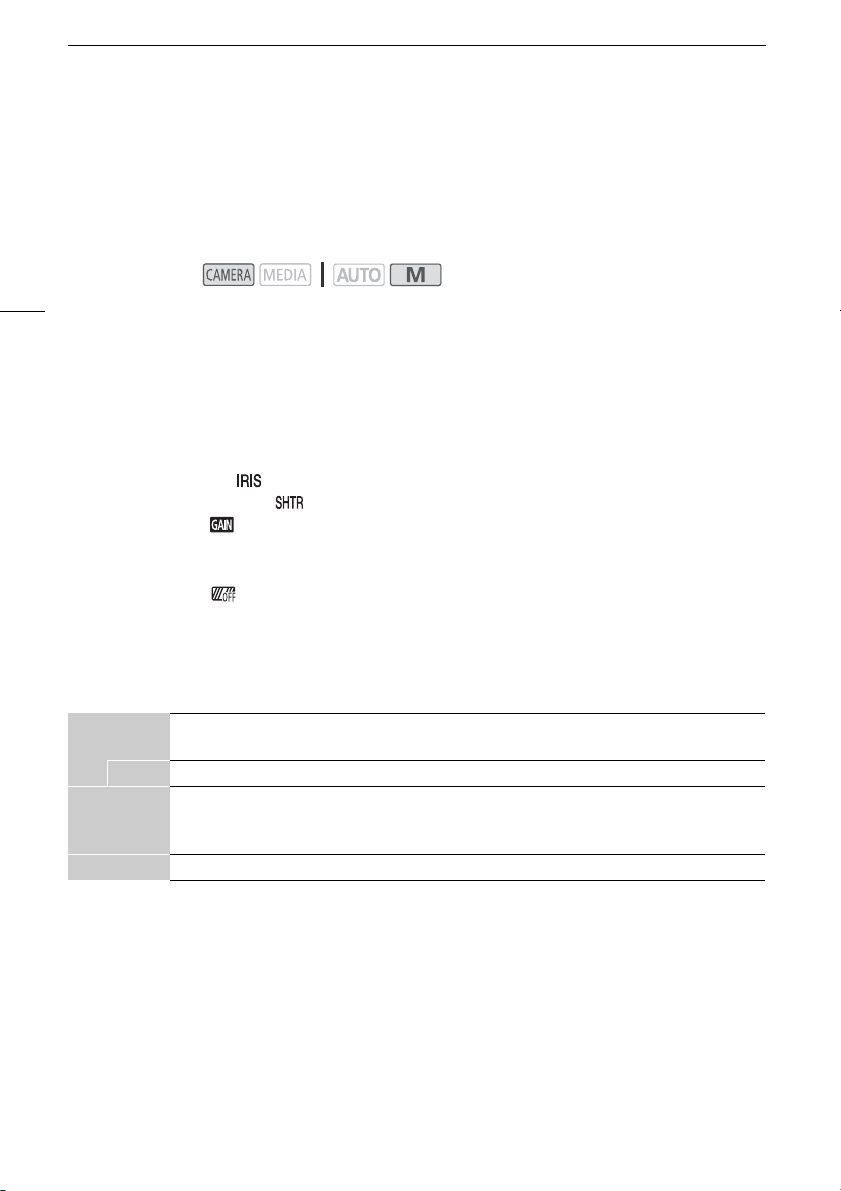
At times, the overall exposure obtained automatically by the camcorder may not be best for your shot.
You can select a shooting mode that will give you a varying amount of control over the aperture,
shutter speed and gain, from partial to full control, while the camcorder automatically adjusts the
settings that you do not.
Operating modes:
42
Manual Exposure (n)
This shooting mode gives you the most control over shooting settings as you can set the aperture,
shutter speed and gain to get the exposure that you want.
1 Set the shooting mode to [n Manual Exposure] (A 39).
• The aperture value, shutter speed and gain value will appear at the left of the screen.
2 Set the aperture, shutter speed and gain.
Aperture: [FUNC] > [ Aperture]
Shutter speed: [FUNC] > [ Shutter Speed]
Gain: [FUNC] > [ Gain]
• An adjustment dial will appear on the screen.
3 Drag your finger along the dial to set the desired value.
• You can select [ ] to display the zebra pattern (A 46, step 2) and check for overexposed
areas.
4 Repeat steps 2 and 3 as necessary to adjust the exposure to the desired level.
5 Select [X].
Available settings
1
Aperture
ND filter When the aperture value is F4.0 or higher: ND1/2, ND1/4, ND1/8
Shutter speed21/63, 1/8, 1/9, 1/10, 1/12, 1/15, 1/17, 1/20, 1/24, 1/25, 1/30, 1/34, 1/40, 1/48, 1/50, 1/60, 1/75,
Gain 0.0 dB to 24.0 dB (1-dB increments)
1
Available values depend on the zoom position. Aperture values displayed on the screen are for
reference only.
2
During slow & fast motion recording, available values will vary depending on the selected slow/fast
motion rate.
3
Only when the frame rate is 23.98P.
F1.8, F2.0, F2.2, F2.4, F2.6, F2.8, F3.2, F3.4, F3.7, F4.0, F4.4, F4.8, F5.2, F5.6, F6.2, F6.7, F7.3,
F8.0
1/90, 1/100, 1/120, 1/150, 1/180, 1/210, 1/250, 1/300, 1/360, 1/420, 1/500, 1/600, 1/720, 1/840,
1/1000, 1/1200, 1/1400, 1/1700, 1/2000
Page 43
Exposure Adjustment
NOTES
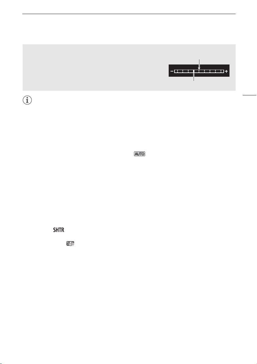
Optimal exposure AE±0
Current exposure
The exposure bar
When the shooting mode is set to n, the exposure bar will appear
on the screen, showing the optimal automatic exposure and
current exposure. When the difference between current and
optimal exposure is larger than ±2 EV, the indicator will flash at the
edge of the exposure bar.
• You can adjust the aperture, shutter speed and gain using the CUSTOM dial (A 84).
Automatic Exposure
Programmed AE (’)
The camcorder automatically sets the shutter speed, aperture and gain (for clips) but you will have the
option to use other functions that are not available in mode.
Set the shooting mode to [’ Programmed AE].
Shutter Priority AE (‚)
With this shooting mode you set the shutter speed manually, for example, to capture fast-moving
subjects in sharp focus or to obtain a brighter image in low-light situations. The camcorder will
automatically adjust other settings to obtain the best exposure.
1 Set the shooting mode to [‚ Shutter-Pri. AE] (A 39).
• The shutter speed will appear at the left of the screen.
2 Open the shutter speed screen.
[FUNC] > [ Shutter Speed]
• An adjustment dial will appear on the screen.
• You can select [ ] to display the zebra pattern (A 46, step 2) and check for overexposed
areas.
3 Drag your finger along the dial to set the desired shutter speed.
• You can also adjust the shutter speed using the CUSTOM dial (A 84).
• For available shutter speeds, see the manual exposure table (A 42).
4 Select [X].
43
Aperture Priority AE (“)
With this shooting mode you set the aperture value manually to control the depth of field, for example,
in order to defocus the background and make the subject stand out more. The camcorder will
automatically adjust other settings to obtain the best exposure.
1 Set the shooting mode to [“ Aperture-Pri. AE] (A 39).
• The aperture value will appear at the left of the screen.
Page 44

Exposure Adjustment
NOTES
2 Open the aperture screen.
[FUNC] > [ Aperture]
• An adjustment dial will appear on the screen.
• You can select [ ] to display the zebra pattern (A 46, step 2) and check for overexposed
areas.
3 Drag your finger along the dial to set the desired aperture value.
44
• You can also adjust the aperture value using the CUSTOM dial (A 84).
• For available aperture values, see the manual exposure table (A 42)
4 Select [X].
• When the shooting mode is set to ‚ or “, depending on the brightness of the subject, the
camcorder may not be able to set the appropriate exposure. In such case the shutter speed (‚) or
aperture value (“) will flash on the screen. Change the aperture/shutter speed as necessary.
Tou c h Ex p os ur e
You can touch the screen to optimize the exposure for a specific subject or area. The camcorder will
automatically adjust the exposure for the selected point and lock the exposure settings. You can even
touch a bright area of the image to try to avoid overexposure (Highlight AE). This function can only be
used when the shooting mode is set to ’, ‚, “ or one of the Special Scene modes, except for
[T Fireworks].
1 Open the exposure screen.
[FUNC] > [y Exposure Comp.]
• An adjustment dial will appear on the screen.
• You can select [ ] to display the zebra pattern (A 46, step 2) and check for overexposed
areas.
2 To use the Highlight AE function, change the touch exposure settings.
[i] > [ Highlights] > [L]
3 Touch the desired area on the LCD screen to optimize and lock the exposure.
•The I mark will flash and the exposure will be adjusted automatically so the area you touched
will be correctly exposed.
• The exposure compensation value ±0 and will appear on the screen. In addition, [ ] will
indicate that the exposure is locked.
• Select [ ] to return the camcorder to automatic exposure.
4 If necessary, drag your finger along the dial to compensate the exposure.
• You can select a compensation level from –3 to +3 in 1/4 increments.
5 Select [X].
• The exposure compensation value and will appear at the left of the screen.
Page 45

Exposure Adjustment
NOTES
Exposure Lock (AE Lock)
You can lock the current exposure settings and use them even when you reframe the picture. This
function can only be used when the shooting mode is set to ’, ‚, “ or one of the Special Scene
modes, except for [T Fireworks].
1 Open the exposure screen.
[FUNC] > [y Exposure Comp.]
• An adjustment dial will appear on the screen.
• You can select [ ] to display the zebra pattern (A 46, step 2) and check for overexposed
areas.
2 Select [ ] to lock the current exposure.
• The exposure compensation value ±0 and will appear on the screen. In addition, [ ] will
indicate that the exposure is locked.
• Select [ ] again to return the camcorder to automatic exposure.
3 Drag your finger along the dial to further compensate the exposure.
• You can select a compensation level from –3 to +3 in 1/4 increments.
• Depending on the brightness of the image and the exposure locked, some values may not be
available and the available exposure compensation range may differ.
4 Select [X].
• The exposure compensation value and will appear at the left of the screen.
Exposure Compensation
You can compensate the exposure that was set using automatic aperture, in order to darken or lighten
the image.
This function can only be used when the shooting mode is set to ’, ‚ or “.
1 Open the exposure screen.
[FUNC] > [y Exposure Comp.]
• If the exposure was locked, select [ ] to unlock the automatic exposure.
• An adjustment dial will appear on the screen.
• You can select [ ] to display the zebra pattern (A 46, step 2) and check for overexposed
areas.
2 Drag your finger along the dial to compensate the exposure.
• You can select a compensation level from –2 to +2 in 1/4 increments.
3 Select [X].
• [AE] and the exposure compensation value will appear at the left of the screen.
45
• Setting the exposure compensation is not available during infrared mode.
• You can adjust the exposure compensation value using the CUSTOM dial (A 84).
• The locked exposure will return to automatic exposure in the following cases:
- When the power switch, camera mode switch or INFRARED switch is operated.
- When the shooting mode is changed.
- When the video configuration is changed.
Page 46
Exposure Adjustment
NOTES
NOTES
ND Filter
Using the ND filter allows you to open up the aperture to obtain a shallower depth of field even when
recording in bright surroundings. You can also use the ND filter to avoid the soft focus caused by
diffraction when using small apertures. The ND filter can be set when the aperture value is F4.0.
This function can only be used when the shooting mode is set to ’, ‚, “ or n.
1 Select [ND Filter].
46
2 Select the desired option and then select [X].
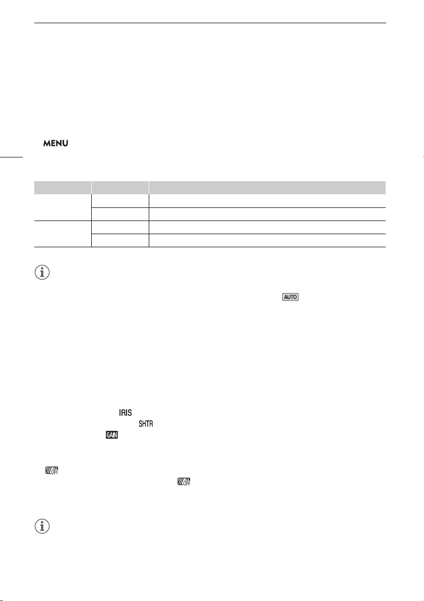
ND filter operation
[j Off] “, n The ND filter will not be used.
• The ND filter is not available with the [T Fireworks] Special Scene mode.
• The ND filter will be set to [k Automatic] when the camera mode is or the shooting mode is
> [v # Camera Setup] > [ND Filter]
ND filter option Shooting mode Description
[k Automatic] “, n When the aperture value is F4.0, you can select the ND filter setting manually.
’, ‚ The camcorder will use the ND filter automatically for automatic exposure.
’, ‚ The camcorder will not use the ND filter for automatic exposure.
set to a Special Scene mode (except for [T Fireworks]).
Using the Zebra Pattern
You can use the zebra pattern to identify areas that might be overexposed, so you can correct the
exposure appropriately. The camcorder offers two levels of zebra pattern: With 100% only areas that
will lose detail in the highlight areas will be identified, while 70% will identify also areas that are
dangerously close to losing detail.
1 Select the aperture, shutter speed, gain or exposure compensation.
Aperture: [FUNC] > [ Aperture]
Shutter speed: [FUNC] > [ Shutter Speed]
Gain: [FUNC] > [ Gain]
Exposure compensation: [FUNC] > [y Exposure Comp.]
2 Select the desired zebra level.
[] > [z 70%] or [{ 100%] > [X]
• To turn off the zebra pattern, select [ Off] instead.
• To return to the previous screen and adjust other settings, select [L] instead of [X].
• The zebra pattern will appear on the overexposed areas of the picture.
• Using the zebra pattern will not affect your recordings.
Page 47
Exposure Adjustment
NOTES
Backlight Correction
When you need to record a scene with constant backlight conditions, you can use backlight correction
to make the picture, especially the darker areas, brighter.
This function cannot be used when the shooting mode is set to [T Fireworks].
1 Select [ BLC Always On].
[FUNC] > [ BLC Always On]
2 Select [ On] and then select [X].
• will appear at the left of the screen and the exposure will be adjusted to account for backlight
conditions.
• Alternatively, you can set an assignable button to [ BLC Always On] (A 85). In that case,
press the assignable button to turn the backlight correction on and off.
• This camcorder also has an automatic backlight correction feature with the > [v Camera
Setup] > [Auto Backlight Correction] setting.
• Backlight correction is not available during infrared mode.
• Backlight correction will be deactivated in the following cases:
- When the power switch, camera mode switch or INFRARED switch is operated.
- When the shooting mode is changed.
- When the frame rate is changed.
47
Page 48
Automatic Gain Control (AGC) Limit
NOTES
Automatic Gain Control (AGC) Limit
When recording in dark surroundings, the camcorder will automatically increase the gain to try to get a
brighter picture. By setting a maximum gain value, you can limit the amount of noise in the picture and
keep a darker look. This function can only be used when the shooting mode is set to ’, ‚ or “.
Operating modes:
48
1 Open the AGC limit adjustment screen.
[FUNC] > [ AGC Limit] > [n]
• An adjustment dial will appear on the screen.
• Select [n] again to return the camcorder to automatic gain control.
2 Drag your finger along the dial to set the desired maximum gain value.
• You can select an AGC limit from 0.0 dB to 23.0 dB. The lower the setting, the lower the AGC
limit.
3 Select [X].
• When an AGC limit is set, and the maximum gain value will appear at the left of the screen.
• The AGC limit cannot be set in the following cases:
- When the exposure is locked (A 45).
- When infrared recording is activated.
• You can adjust the AGC limit using the CUSTOM dial (A 84).
Page 49
White Balance
White Balance
The camcorder uses an electronic white balance process to calibrate the picture and produce
accurate colors under different lighting conditions. This function can only be used when the shooting
mode is set to ’, ‚, “ or n.
Operating modes:
1 Select [ White Balance].
[FUNC] > [ White Balance]
2 Select the desired option and then select [X].
• If you selected [ Color Temperature], [ Set 1] or [ Set 2] and wish to change the color
temperature value or register a new custom white balance, continue with the appropriate
procedure below instead of selecting [X].
• The icon of the selected option will appear at the left of the screen.
To set the color temperature ([ Color Temperature])
3 Select [i].
• An adjustment dial will appear on the screen.
4 Drag your finger along the dial to set the color temperature value.
5 Select [X].
To set a custom white balance ([ Set 1] or [ Set 2])
3 Point the camcorder at a gray card or white object so that it fills the frame at the center of
the screen and then select [Å].
• When the Å icon stops flashing, the procedure is completed. The setting is retained even if you
turn off the camcorder.
4 Select [X].
Options
[ Automatic]: The camcorder automatically sets the white balance for natural looking colors.
[¼ Daylight]: To record outdoors on a bright day.
[É Tungsten]: To record under tungsten and tungsten-type (3-wavelength) fluorescent lighting.
[ Color Temperature]:
Allows you to set the color temperature between 2,000 K and 15,000 K.
[ Set 1], [ Set 2]:
Use the custom white balance settings to make white subjects appear white
under colored lighting.
49
Page 50

White Balance
NOTES
• When you select a custom white balance:
- Do not adjust the zoom to the digital zoom range (light blue area of the zoom bar).
- Reset the white balance when you change locations or the lighting or other conditions change.
- Depending on the light source, Å may keep flashing. The result will still be better than with
[Automatic].
• If you set an assignable button to [Å Set WB] (A 85), you can press the button to register a
50
custom white balance after you point the camcorder at a gray card or white object.
• Using a custom white balance may provide better results in the following cases:
- Changing lighting conditions
-Close-ups
- Subjects in a single color (sky, sea or forest)
- Under mercury lamps, certain types of fluorescent lights and LED lights
• Adjusting the white balance is not available when infrared recording is activated.
• If you set an assignable button to [Ä WB Priority] (A 85), you can press the button to switch to a
frequently used white balance setting pre-selected with > [v Camera Setup] > [Set WB
Priority].
Page 51
Using Looks
NOTES
Using Looks
You have the option of adding a “look” to your recordings. A look is a combination of various picture
settings, such as color depth and sharpness, that can enhance the recording's visual quality.
This function can only be used when the shooting mode is set to ’, ‚, “ or n.
Operating modes:
1 Open the looks screen.
[FUNC] > [ Looks]
2 Adjust the detailed settings.
[i] > Select [–] or [+] to adjust the value
• You can also drag your finger along the adjustment bar.
• The sharpness, contrast and color depth can be adjusted as follows:
[Sharpness]: 0 (softer image) to 7 (sharper image)
[Contrast]: –4 (low contrast) to +4 (high contrast)
[Color Depth]: –4 (shallower colors) to +4 (richer colors)
3 Select [X].
• Looks are not available during infrared mode.
51
Page 52
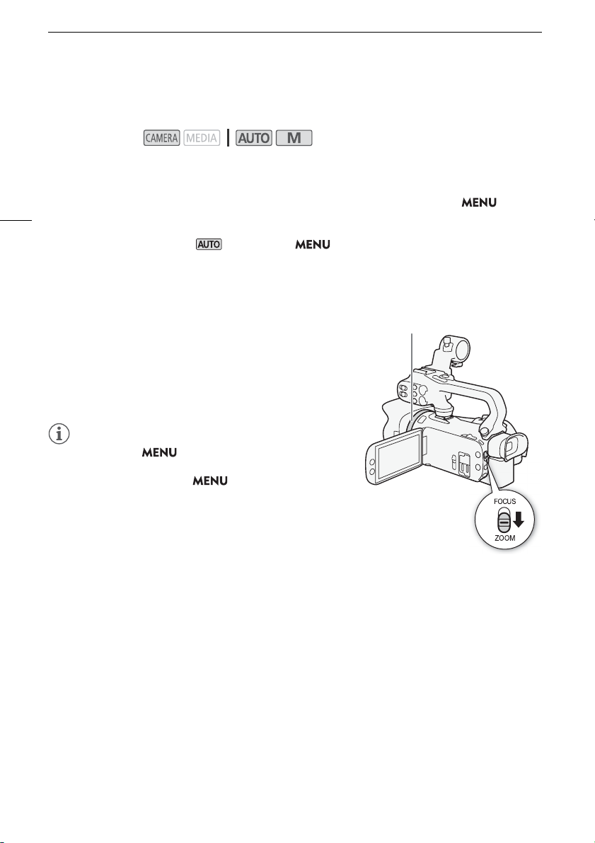
Zooming
NOTES
Focus/zoom ring
Zooming
Operating modes:
To zoom in and out, you can use the focus/zoom ring, the zoom rockers on the camcorder and handle
unit, or the zoom controls on the touch screen. You can also zoom using the optional RC-V100
Remote Controller (A 81).
In addition to the 20x optical zoom, you can turn on the digital zoom* (400x) with the >
52
[v Camera Setup] > [Digital Zoom] setting. This camcorder also features a digital tele-converter,
which allows you to enlarge the image on the screen digitally.
* Digital zoom is not available in mode or when > [v Camera Setup] > [Conversion
Lens] is set to [¿ WA-H58].
Using the Focus/Zoom Ring
1 Set the focus/zoom ring switch to ZOOM.
2 Turn the focus/zoom ring to adjust the zoom.
• Turn the focus/zoom ring slowly for a slow zoom; turn it
faster for faster zooms.
• The zoom bar that appears on the screen indicates the
approximate zoom position.
• You can use the > [v Camera Setup] > [Focus/
Zoom Ring Operation] setting to disable the focus/zoom ring’s
operation. You can use the > [v Camera Setup] >
[Zoom Ring Direction] setting to select the direction of the
focus/zoom ring’s operation when it is used to adjust the
zoom.
• If you turn the focus/zoom ring too quickly, the camcorder
may not be able to zoom immediately. In such case, the
camcorder will zoom after you finish turning the ring.
Page 53
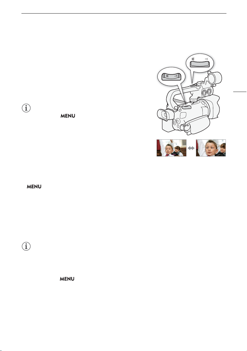
Zooming
NOTES
NOTES
W Zoom out
T Zoom in
Using the Zoom Rockers
Move the zoom rocker on the camcorder or handle unit
toward T (wide angle) to zoom out. Move it toward S
(telephoto) to zoom in.
• By default, the grip zoom rocker (the rocker near the grip belt)
operates at a variable speed – press gently for a slow zoom;
press harder for faster zooms. You can perform the following
procedure to adjust the zoom speed and to select a constant
speed.
• You can use the > [v Camera Setup] > [Handle
Zoom Operation] setting to disable the handle unit zoom
rocker’s operation.
Setting the Zoom Speed
You can set the zoom speed for the zoom rockers.
To set the zoom speed of the grip zoom rocker
First, set the overall zoom speed to one of three levels. Next, select whether the zoom rocker operates
at a constant or variable speed. Refer to the following table for a summary of the zoom speed.
1 Select the overall zoom speed level.
> [v ! Camera Setup] > [Zoom Speed Level] > Desired zoom speed level > [L]
• You can select one of three levels, [Z Fast], [[ Normal] or [] Slow].
2 Select whether to use a variable or constant zoom speed.
[Grip Zoom Speed] > [Y] (variable) or [X] (constant)
• If you selected [Y], skip to step 4.
3 Select [Ï] or [Ð], or drag your finger along the adjustment bar, to set the desired constant
speed.
4 Select [X].
53
• When [Zoom Speed Level] is set to [Z Fast], the camcorder may pick up and record lens
operation sounds.
• When you are using an external microphone while recording, the sound made by the camcorder’s
internal machinery while zooming may be recorded in the clip.
• You can use the > [v Camera Setup] > [Grip Zoom Operation] setting to disable the grip
zoom rocker’s operation.
Page 54
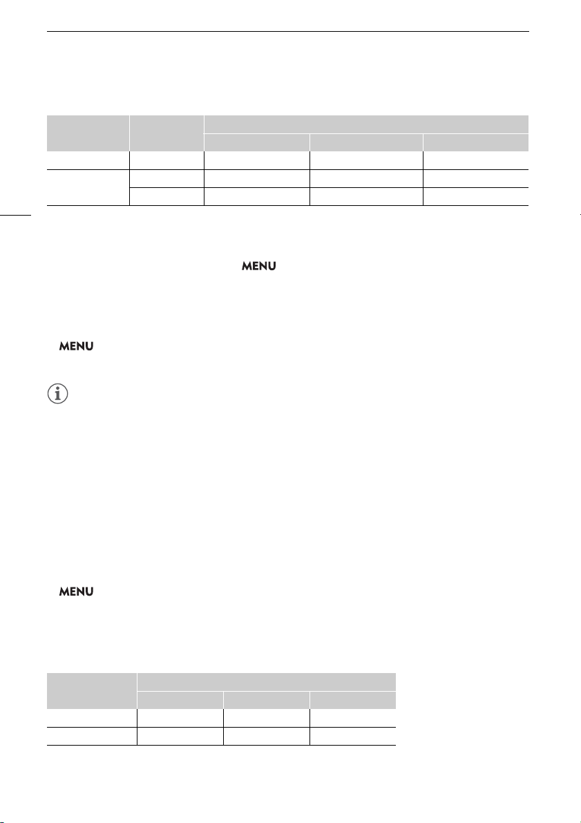
Zooming
NOTES
Approximate zoom speeds* (grip zoom rocker)
[Grip Zoom
Speed] setting
[Y] (variable) – 3 sec. to 3 min. 25 sec. 2.5 sec. to 2 min 10 sec. 1.8 sec.** to 45 sec.
[X] (constant) 1 (slowest) 3 min. 25 sec. 2 min 10 sec. 45 sec.
54
* Measured from full wide-angle to full telephoto.
** The camcorder will have more trouble focusing automatically while zooming.
Selected
constant speed
16 (fastest) 3 sec. 2.5 sec. 1.8 sec.**
[] Slow] [[ Normal] [Z Fast]
[Zoom Speed Level] setting
To use high-speed zoom in standby mode
When high-speed zoom is activated and > [v Camera Setup] > [Grip Zoom Speed] is set
to [Y] (variable zoom speed), in record standby mode you will be able to zoom at the highest speed
available ([Z Fast]). Nevertheless, the zoom speed while recording will be determined by the [Zoom
Speed Level] setting.
1 Select [High-Speed Zoom].
> [v " Camera Setup] > [High-Speed Zoom]
2Select [i On] and then select [X].
• When pre-recording is activated, the zoom speed will be determined by the [Zoom Speed Level]
setting even in record standby mode.
• When [Zoom Speed Level] is set to [Z Fast], the zoom speed will not change even in record
standby mode.
To set the speed of the handle zoom rocker
For the handle zoom rocker, first set the overall zoom speed to one of three levels. The zoom rocker
operates at a constant speed that you can select. To use the zoom rocker, make sure you attach the
handle unit to the camcorder in advance. Refer to the following table for a summary of the zoom
speed.
1 Select the overall zoom speed level (step 1, A 53).
2 Select [Handle Zoom Speed].
> [v " Camera Setup] > [Handle Zoom Speed]
3Select [Ï] or [Ð], or drag your finger along the adjustment bar, to set the desired constant
speed.
4Select [X].
Approximate zoom speeds* (handle unit zoom rocker)
Selected
constant speed
1 (slowest) 3 min. 25 sec. 2 min. 10 sec. 45 sec.
16 (fastest) 3 sec. 2.5 sec. 1.8 sec.**
* Measured from full wide-angle to full telephoto.
** The camcorder will have more trouble focusing automatically while zooming.
[] Slow] [[ Normal] [Z Fast]
[Zoom Speed Level] setting
Page 55
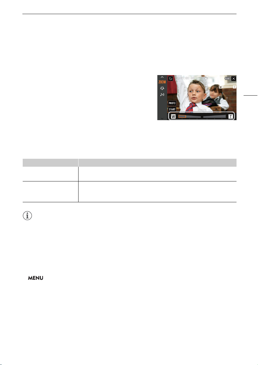
Zooming
NOTES
Using the Touch Screen’s Zoom Controls
1 Open the onscreen zoom controls.
[FUNC] > [R Zoom]
• The zoom controls appear at the bottom the screen.
2 Touch the zoom controls to operate the zoom.
•Touch anywhere within the V area to zoom out or
anywhere within the U area to zoom in. Touch closer to
the center for a slow zoom; touch closer to the V/U
icons for faster zooms.
3 Select [X].
Using an Optional Remote Controller
The zoom speeds when using the optional RC-V100 Remote Controller or a commercially available
remote control connected to the REMOTE terminal are different.
Zoom speeds for remote operation
Accessory Zoom speed
RC-V100 Remote Controller
(optional)
Commercially available
remote controls
Variable speed: The greater the angle at which the RC-V100's ZOOM dial is rotated
from the center, the faster the zoom.
If the remote control does not support variable zoom: Constant zoom speed.
If the remote control supports variable zoom: Variable zoom according to the remote
control's settings.
55
• When an optional RC-V100 Remote Controller is connected to the camcorder, you can zoom with
the remote controller's ZOOM dial. At default settings, turn the dial right to zoom in (S) and left to
zoom out (T).
Soft Zoom Control
Soft zoom control allows you to start and/or stop the zoom gradually.
1 Select [Soft Zoom Control].
> [v ! Camera Setup] > [Soft Zoom Control]
2 Select the desired option and then select [X].
Options
[j Off]: Use this setting if you do not intend to use soft zoom control.
[¬ Start]: Zoom starts gradually.
[® Stop]: Zoom stops gradually.
[¯ Start & Stop]: Zoom start and stops gradually.
Page 56
Zooming
NOTES
Digital Tele-Converter
Using the digital tele-converter, you can digitally increase the focal length of the camcorder by a factor
of approx. 2 and record the enlarged image.
Operating modes:
1 Select [Digital Zoom].
56
2 Select [ Digital Tele-conv.] and then select [X].
3 Open the zoom controls.
4 Select [ ] (digital tele-converter) and then select [X].
• You can attach the optional tele-converter and use it in conjunction with this function to increase the
• The digital tele-converter cannot be set while recording or when > [v Camera Setup] >
• The image is digitally processed so the image will deteriorate throughout the zoom range.
• The digital tele-converter will be deactivated if the resolution is switched between 3840x2160 and
> [v ! Camera Setup] > [Digital Zoom]
[FUNC] > [R Zoom]
• The center of the screen will be enlarged approximately 2 times and the icon will appear.
• Select [ ] again before closing the screen to deactivate the digital tele-converter.
effect.
[Conversion Lens] is set to [¿ WA-H58].
another one.
Page 57
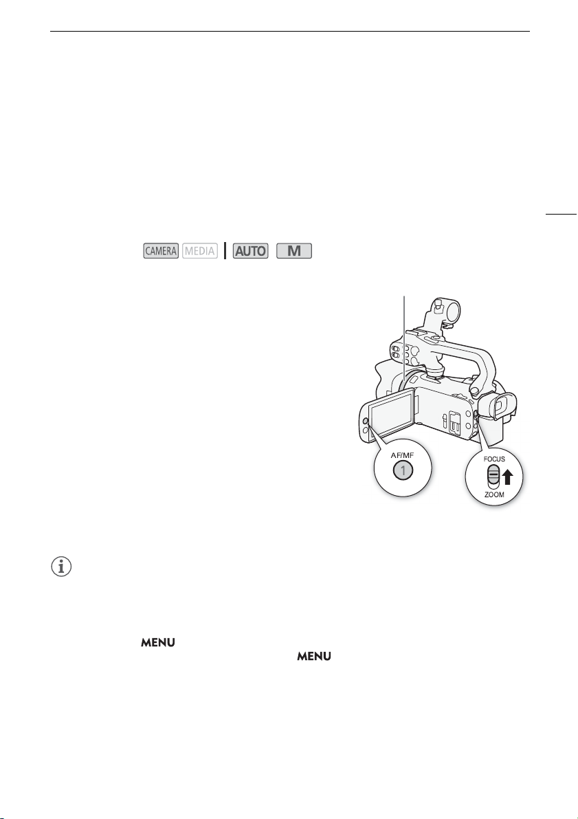
Focus Adjustment
NOTES
Focus/zoom ring
Focus Adjustment
The camcorder offers manual and automatic focus adjustment. When using manual focus, you can
use the focus preset and peaking functions to assist you. When using automatic focus, you can use
face detection & tracking to help make sure the subject is in focus.
Manual Focus
Use the focus/zoom ring to focus manually. Manual focus is available even after touching the screen to
adjust the focus automatically.
Operating modes:
* Focus adjustment is available using only the focus/zoom ring.
1 Set the focus/zoom ring switch to FOCUS.
To focus using only the focus/zoom ring
2 Press the AF/MF button.
• [MF] will appear on the screen.
3 Turn the focus/zoom ring to adjust the focus.
To focus by touching the subject on the screen
2 Open the focus controls.
[FUNC] > [< Focus]
• The focus adjustment screen will appear.
3 Touch a subject that appears inside the frame.
• The Touch AF mark (I) will flash and the focusing distance
• To return the camcorder to autofocus, touch m.
4 If necessary, turn the focus/zoom ring to further adjust the focus.
5Touch [X] to close the focus adjustment screen.
• If you operate the zoom after focusing, the focus on the subject may be lost.
• If you focus manually and then leave the camcorder with the power turned on, the focus on the
subject may be lost after a while. This possible slight shift in focus is a result of the internal
temperature rising. Check the focus before resuming shooting.
• You can use the > [v Camera Setup] > [Focus/Zoom Ring Operation] setting to disable
the focus/zoom ring’s operation. You can use the > [v Camera Setup] > [Focus Ring
Direction] and [Focus Ring Response] settings to change the direction and responsiveness of the
focus/zoom ring when it is used to adjust the focus.
57
*
will be adjusted automatically.
Page 58
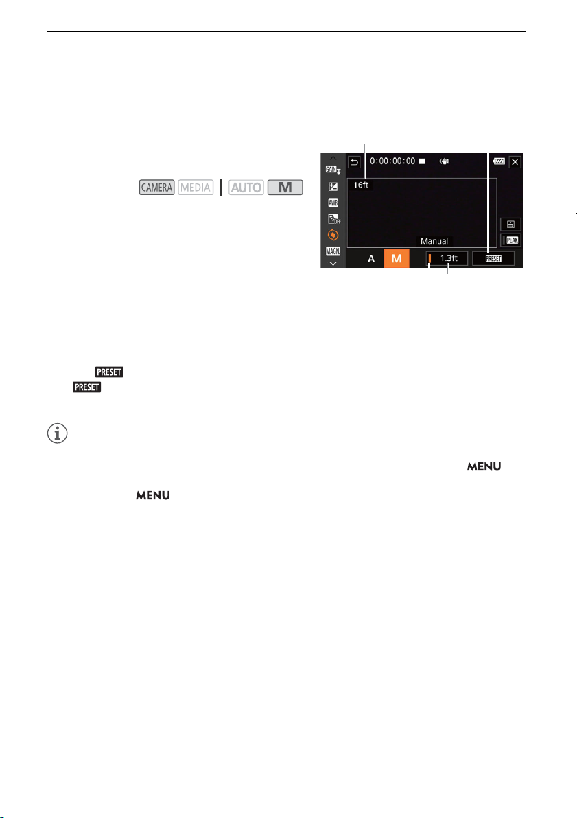
Focus Adjustment
NOTES
Focus preset button
(in orange: focus
preset activated)
Preset focus
position
Current focusing
distance
Select to return to the
preset focus position
Focus Preset
When manual focus is activated, you can register a
certain focus point and then, after you focus manually
somewhere else, have the camcorder return to the
preset focus position.
Operating modes:
58
1 Activate the manual focus and adjust the focus to
the desired position (A 57).
• The current approximate focusing distance will
appear inside the focus frame and in the focus
preset button.
2 Select the focus preset button to save the current
focus position.
• The indicator inside the button will turn orange to
show the focus preset function was activated.
• Select the focus preset button again to turn off the focus preset function.
3 Adjust the focus as necessary using touch AF or the focus/zoom ring.
4 Select [ ] to return to the preset focus position.
• [ ] will be grayed out while adjusting the focus or zoom.
• To end focus preset, select the focus preset button.
• The preset focus position will be canceled when the camcorder is turned off.
• Focusing distances are approximate. You can change the distance units used with the >
[£ Display Setup] > [Distance Units] setting.
• You can use the > [v Camera Setup] > [Focus Preset Speed] setting to set the speed at
which the camcorder returns to the preset focus position.
Using the Focus Assistance Functions
In order to focus more accurately, you can use the following focus assistance functions: peaking,
which creates a clearer contrast by emphasizing the outlines of the subject; and magnification, which
enlarges the image on the screen. You can use peaking and magnification simultaneously for greater
effect.
Page 59

Focus Adjustment
NOTES
Peaking
When peaking is activated, the edges of objects in focus will be highlighted in red, blue or yellow on
the screen. In addition, you can choose to switch the screen to black & white while peaking is
activated, further emphasizing the edges.
1 Open the focus controls.
[FUNC] > [< Focus]
2 If necessary, change the peaking settings.
[i] > Desired options > [L]
• For the black & white setting: Select [Off] or [On]. For the peaking color: Select [Red], [Blue] or
[Yellow].
3 Select [O] and then select [X].
• Peaking is activated and edges are highlighted.
•Select [O] again (before closing the menu) to turn off the peaking effect.
Magnification
1 Activate magnification.
[FUNC] > [^ Magnification] > [OK]
• ^ appears at the lower right of the screen and the center of the screen* is magnified 2 times.
• The frame displayed at the bottom right corner of the screen (magnification frame) shows the
approximate part of the image shown magnified.
2 If necessary, move around the magnification frame to check other parts of the image.
• Drag your finger on the LCD screen or push the joystick (ÝÞ).
3 Select [X] to cancel the magnification.
* If the face detection or tracking frame is displayed on the screen, the area around the frame will be
magnified instead.
59
• About peaking/magnification:
- The assistance functions are only displayed on the camcorder's screen. They will not appear on
video output from the camcorder and will not affect your recordings.
- Magnification is not available while the color bars are displayed.
• If you set an assignable button to [^ Magnification] (A 85), you can press the button to activate
the magnification.
• Magnification will deactivate when you start recording but you can activate and deactivate it again
while recording.
Page 60
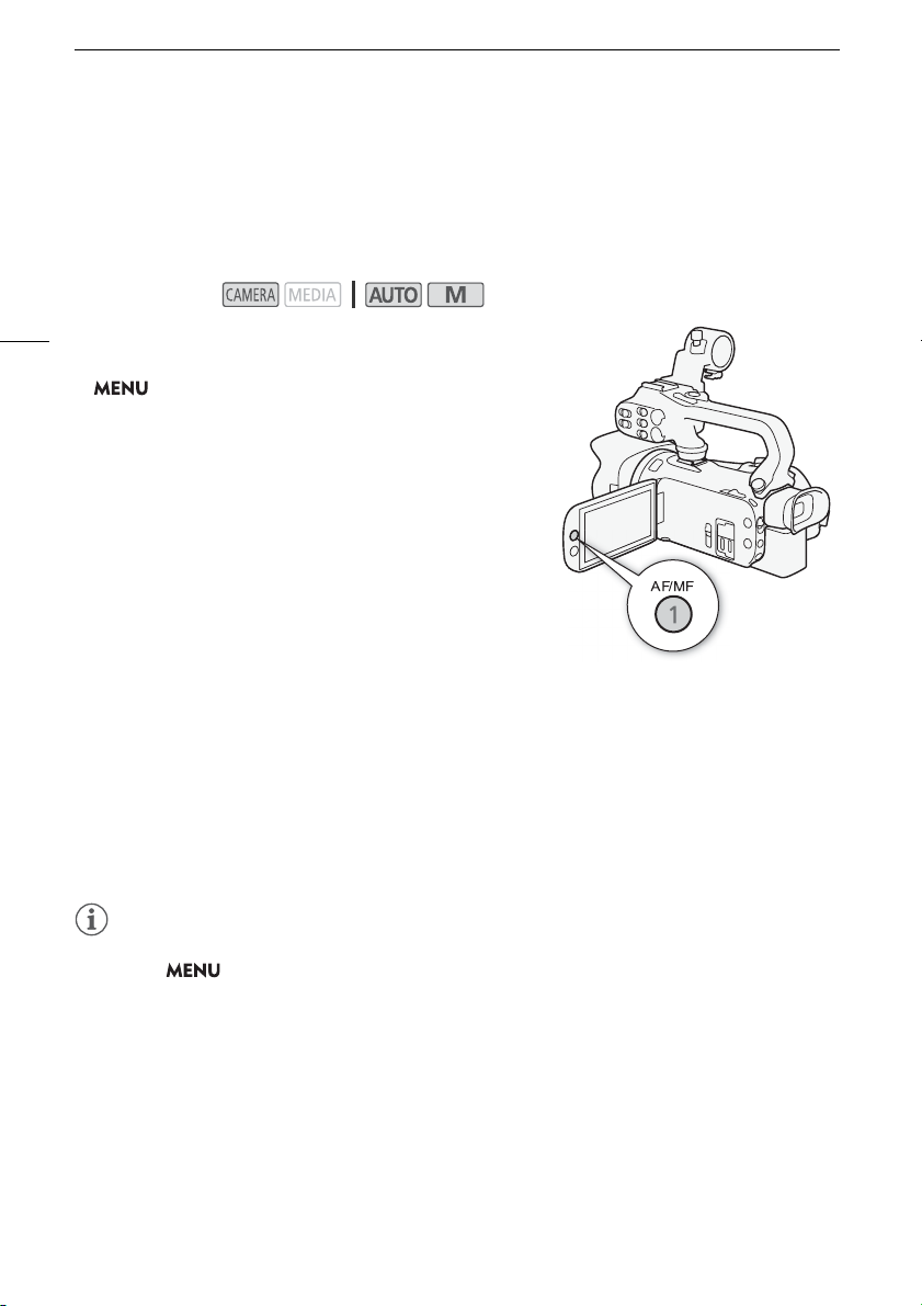
Focus Adjustment
NOTES
Autofocus
When autofocus is activated, the camcorder continuously adjusts the focus on the subject in the
center of the screen. The focusing range is 1 cm (0.39 in.; at full wide-angle, measured from the front
of the lens barrel) to G and 60 cm (2 ft.; throughout the zoom range, measured from the front of the
lens barrel) to G. Perform the following procedure to set the autofocus speed.
Operating modes:
60
1 During manual focus: Press the AF/MF button.
2Select [AF Mode].
> [v " Camera Setup] > [AF Mode]
3 Select the desired option and then select [X].
Options
[= Instant AF]: Sets the autofocus to Instant AF. The focus is adjusted at the highest speed. This
mode is useful even when recording in very bright or low-light surroundings. This
mode uses both the TTL system and external sensor for focusing.
[? Medium AF]: Sets the autofocus to Medium AF. The camcorder focuses more smoothly on the
subject than when using the [= Instant AF] setting. This mode uses both the
TTL system and external sensor for focusing.
[@ Normal AF]: Sets the autofocus to Normal AF. The autofocus adjustment is made at a stable
speed.
• The AF mode cannot be selected in the following cases.
- When > [v Camera Setup] > [Conversion Lens] is set to an option other than
[j Off].
- When infrared recording is activated.
• While using autofocus, you can turn the focus/zoom ring to focus manually. When you stop turning
the ring, the camcorder returns to autofocus. This is useful in situations such as when focusing on a
subject on the other side of a window.
• When the shooting mode is set to [T Fireworks], the focus will be set to G and cannot be
changed.
• Autofocus takes longer to focus when the frame rate is 29.97P or 23.98P than when it is 59.94P.
Page 61
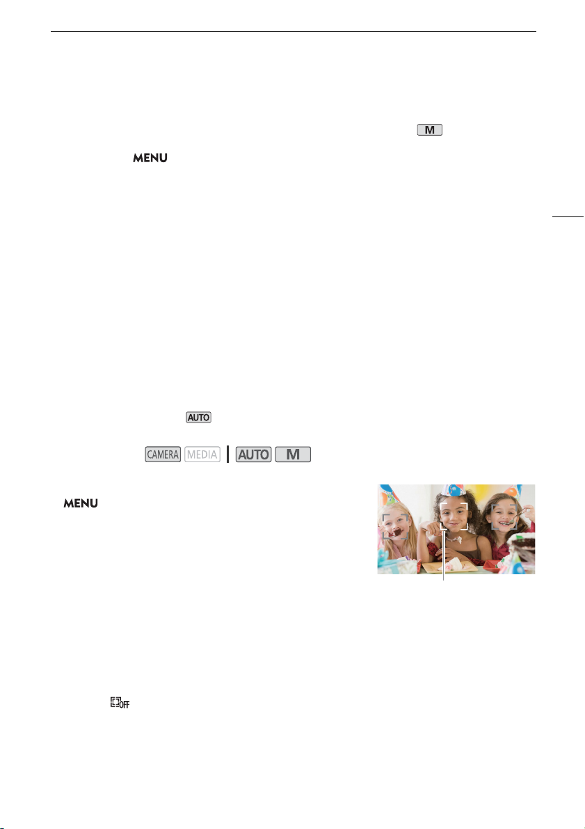
Focus Adjustment
Main subject
• About soft focus due to smaller apertures: When recording in bright surroundings, the
camcorder closes down the aperture. This may cause the picture to appear blurred and is more
noticeable toward the wide angle end of the zoom range. In such case, in mode, select the
[’ Programmed AE], [‚ Shutter-Pri. AE], [“ Aperture-Pri. AE] or [n Manual Exposure] shooting
mode and set > [v Camera Setup] > [ND Filter] to [k Automatic].
• When recording under dark conditions, the focusing range narrows and the picture may appear
blurred.
• Autofocus may not work well on the following subjects or in the following cases. In such case, focus
manually.
- Reflective surfaces - Through dirty or wet windows
- Subjects with low contrast or without vertical lines - Night scenes
- Fast moving subjects
- When subjects are at different distances.
Face Detection & Tracking
During autofocus, the camcorder automatically detects people’s faces and uses this information to
select the optimal focus and exposure settings. When a face cannot be detected, the camcorder can
adjust the focus using autofocus. When multiple faces are detected, you can use tracking to have the
camcorder track and optimize settings for a different subject. You can also use tracking to optimize
settings for moving subjects such as pets. You must use the touch screen to select the subject.
By default, the face detection & tracking function is activated. If it was turned off, start the procedure
from step 1 to activate it. In mode, face detection & tracking is always activated and cannot be
turned off.
Operating modes:
61
1 Activate face detection & tracking.
> [v " Camera Setup] > [Face Detection &
Trac ki ng ] > [i On}] > [X]
• } will appear at the left of the screen.
2 Point the camcorder at the subject.
• A white frame will appear around the face of the main
subject. Other faces will have gray frames.
3 If necessary, touch the desired subject on the screen
to select a different main subject.
• To select a different person: Touch a face with a gray frame. The face detection frame will change to
a white double frame £ (tracking frame). The camcorder will track the subject as it moves.
• To select other moving subjects: In autofocus mode only, you can touch [£] and then touch any
other moving subject, such as a pet. The frame will change to a white double frame £ (tracking
frame). The camcorder will track the subject as it moves.
• Touch [ ] to remove the frame and cancel the tracking.
Page 62

Focus Adjustment
NOTES
Limiting Autofocus to Faces
While using autofocus, you can limit the autofocus function only to cases when a subject’s face is
detected and use manual focus for all other scenes. The camcorder will also adjust the brightness
when focusing automatically on the subject’s face.
Set an assignable button to [~ Face Only AF] (A 85) and press the button.
• ~ appears on the screen.
62
• The camcorder may mistakenly detect the faces of non-human subjects. In such case, turn face
detection & tracking off.
• When face detection & tracking is activated, the slowest shutter speed used by the camcorder is
1/30 (1/24 if the frame rate is set to 23.98P).
• In certain cases, faces may not be detected correctly. Typical examples include:
- Faces extremely small, large, dark or bright in relation to the overall picture.
- Faces turned to the side, upside down, at a diagonal or partially hidden.
• Face detection & tracking cannot be used in the following cases.
- When the shooting mode is set to [Q Night Scene], [R Low Light] or [T Fireworks].
- When the shutter speed used is slower than 1/30 (1/24 if the frame rate is set to 23.98P).
- When the digital zoom is activated at more than 80x zoom.
- During infrared mode.
• Touching somewhere with a color or pattern unique to the subject will make it easier to track.
However, if there is another subject in the vicinity that shares similar characteristics to the selected
subject, the camcorder may start tracking the incorrect subject. Touch the screen again to select
the desired subject.
• In certain cases, the camcorder may not be able to track the subject. Typical examples include:
- Subjects extremely small or large in relation to the overall picture.
- Subjects too similar to the background.
- Subjects lacking sufficient contrast.
- Fast moving subjects.
- When shooting indoors with insufficient lighting.
• Autofocus limited to faces will be deactivated in the following cases:
- When the power switch, camera mode switch or INFRARED switch is operated.
- In the same cases that face detection & tracking cannot be used (see above).
- When the camcorder is switched between autofocus and manual focus.
- When the assignable button is no longer assigned to [~ Face Only AF].
Page 63
Image Stabilization
NOTES
Powered IS
To use Powered IS, you will first need to set an assignable button to [È Powered IS].
1 Set an assignable button to [È Powered IS] (A 85).
2 Press and hold the assignable button as long as you want to activate Powered IS.
• È appears in yellow while Powered IS is activated.
• You can change the operation of the assignable button set to [È Powered IS] (long press
or toggle on/off) with the > [v Camera Setup] > [Powered IS Button] setting.
• Powered IS is available even when [Image Stabilizer] is set to [® Off].
Image Stabilization
Use the image stabilizer to compensate for camcorder shake in order to achieve steadier shots. The
camcorder offers 3 methods of image stabilization.
Standard IS (Å): Standard IS compensates for a lower degree of camcorder shake, for example, for
handheld shots while you remain stationary, and is suitable for shooting natural-looking scenes.
Dynamic IS (Ä): Dynamic IS compensates for a higher degree of camcorder shake, such as when
shooting while walking, and is more effective as the zoom approaches full wide angle.
Powered IS (Ç): Powered IS is most effective when you are stationary and zooming in on far
subjects using high zoom ratios (the more you approach the telephoto end). This mode is not suitable
for tilting and panning shots.
Operating modes:
Dynamic IS or Standard IS
1 Select [Image Stabilizer].
> [v # Camera Setup] > [Image Stabilizer]
2 Select [¯ Standard] (Standard IS) or [° Dynamic] (Dynamic IS) and then select [X].
•Select [® Off] instead to turn off the image stabilization, for example, when the camcorder is
mounted on a tripod.
• The icon of the selected mode appears at the top center of the screen.
63
• If the degree of camcorder shake is too high, the image stabilizer may not be able to fully
compensate.
• For surveying and following shots, when you pan the camcorder from side to side or tilt it up and
down, we recommend setting [Image Stabilizer] to [Ä Dynamic] or [Å Standard].
• Powered IS will be deactivated when the camcorder is turned off.
• About Dynamic IS:
- The angle of view will change when [Image Stabilizer] is set to an option other than
[Ä Dynamic].
- When using Dynamic IS, the edges of the picture may be adversely affected (ghosting, artifacts
and/or dark areas may appear) when compensating for a high degree of camcorder shake.
Page 64
Setting the Time Code
Setting the Time Code
The camcorder generates a time code signal and records it with the recorded clips. The time code
signal can be output from the SDI OUT terminal (s only) and HDMI OUT terminal.
Depending on the frame rate used, you may be able to select between a drop frame an non-drop
frame time code signal (A 66). Though the time code display style is different for DF and NDF, in this
section the NDF display style is used for simplicity’s sake.
64
Operating modes:
Selecting the Time Code Mode
1 Select [Time Code Mode].
> [3 " Recording Setup] > [Time Code Mode]
2 Select the desired option and then select [X].
• If you selected [ Regen.], you do not need to perform the following procedures to set the
time code running mode or the time code’s initial value.
Options
[ Preset]: The time code starts from an initial value you can select in advance. The default
initial time code is 00:00:00:00.
See the following procedures to select the time code running mode and set the
initial time code.
[ Regen.]: The camcorder will read the selected SD card and the time code will continue from
the last time code recorded on the card. The time code runs only while recording
so clips recorded consecutively on the same SD card will have continuous time
codes.
Setting the Time Code Running Mode
If you set the time code mode to [ Preset], you can select the time code running mode.
1 Select [Time Code Running Mode].
> [3 " Recording Setup] > [Time Code Running Mode]
2 Select the desired option and then select [X].
Options
[ Rec Run]: The time code runs only while recording so clips recorded consecutively on the
[ Free Run]: The time code starts running the moment you confirm the selection and keeps
same SD card will have continuous time codes.
running regardless of the camcorder’s operation.
Page 65
Setting the Time Code
NOTES
Setting the Time Code’s Initial Value
If you set the running mode to [ Preset], you can set the initial value of the time code.
1 Select [Initial Time Code].
> [3 # Recording Setup] > [Initial Time Code]
• The time code setting screen appears with an orange selection frame indicating the hours.
• Select [Reset] to reset the time code to [00:00:00:00] and return to the previous screen. If the
running mode is set to [ Free Run], the time code will be reset the moment you select the
button and keep running continuously from 00:00:00:00.
2 Select [Í] or [Î] to set the value for the hours and then select the minutes field.
• Change the rest of the fields (minutes, seconds, frame) in the same way.
3 After completing all the fields of the time code, select [OK].
• Select [Cancel] to close the screen without changing the time code.
• If the running mode is set to [ Free Run], the time code will start running from the time code
entered the moment you select [OK].
4 Select [X].
• When the frame rate is set to 23.98P, the frames value in the time code runs from 0 to 23. For other
settings, it runs from 0 to 29.
•However, if > [£ Display Setup] > [SDI/HDMI Scan Mode] (s only) or [HDMI Scan
Mode] (t only) is set to [ PsF (Forced 1080i)], even when the frame rate is set to 23.98P,
the frames value of the time code output from the SDI OUT terminal (s only) and HDMI OUT
terminal will be converted so it runs from 0 to 29.
• You can use the > [3 Recording Setup] > [HDMI Time Code] setting to turn time code
output from the HDMI OUT terminal on or off.
• When slow & fast motion recording is activated, you cannot select the [ Free Run] running
mode. Conversely, when pre-recording is activated, [ Free Run] is set automatically and
cannot be changed.
• When slow & fast motion recording is activated, the time code signal cannot be output from the SDI
OUT terminal (s only) or HDMI OUT terminal.
• When you are using the [ Free Run] running mode, the time code will continue running as
long as the built-in backup battery has some charge left, even if you disconnect all other power
sources. However, this is less accurate than when the camcorder is on.
65
Page 66
Setting the Time Code
NOTES
Selecting Drop Frame or Non-Drop Frame
You can select between a drop frame (DF) or non-drop frame (NDF) time code, depending on how you
plan to use your recordings. However, when the frame rate is set to 23.98P, the time code is set to
non-drop frame (NDF) and cannot be changed.
1 Select [DF/NDF].
> [3 # Recording Setup] > [DF/NDF]
66
2 Select [ DF] or [ NDF] and then select [X].
• The time code display will differ depending on the setting. When you select [ DF], the time
code will appear as [00:00:00.00]; when you select [ NDF], it will appear as [00:00:00:00].
• When you mix drop frame and non-drop frame time codes, there might be a discontinuity in the time
code at the point where the recording starts.
Page 67
Setting the User Bit
NOTES
Setting the User Bit
The user bit display can be selected from the date or the time of recording, or an identification code
consisting of 8 characters in the hexadecimal system. There are sixteen possible characters: the
numbers 0 to 9 and the letters A to F. The user bit will be output from the SDI OUT terminal (s
only) and HDMI OUT terminal.
Operating modes:
1 Open the [User Bit Settings] screen.
> [3 # Recording Setup] > [User Bit Type] > [i]
• To set the time for the user bit, select [ Time] instead; to set the date for the user bit, select
[ Date]. Then, select [
• The user bit setting screen will appear with the orange selection frame on the leftmost digit.
• To reset the user bit to [00 00 00 00], select [Reset].
• Select [Cancel] to close the screen without setting the user bit.
2 Select the digit you want to change and then select [Í] or [Î] to change it as necessary.
3 Select another digit you want to change.
4 Change the rest of the digits in the same way.
5 Select [OK] and then select [X].
• The user bit will not be recorded with clips that are recorded to an SD card.
X]. The rest of the procedure is not necessary.
67
Page 68
Recording Audio
Recording Audio
The camcorder features 4-channel linear PCM or 2-channel AAC audio recording and playback. The
sampling frequency is 48 kHz and the audio sampling bit depth is 16 bit.
You can record audio using the built-in stereo microphone, commercially available external
microphone (INPUT 1/INPUT 2 terminals*, MIC terminal) or line input (INPUT 1/INPUT 2 terminals*).
Using the INPUT 1/INPUT 2 terminals, you can select the audio input independently for channel 1
(CH1) and channel 2 (CH2).
68
The audio signal will be output along with the video signal from the SDI OUT terminal (s only) and
HDMI OUT terminal. You can record this audio signal on an external recorder.
* Available only when the handle unit is attached to the camcorder.
Operating modes:
Selecting the Audio Recording Format
You can set the audio recording format to AAC (2 channels, 16 bit) or linear PCM (4 channels, 16 bit).
When the resolution is set to 1280x720, the audio format is set to AAC and cannot be changed.
1 Select [¸ Audio Format].
> [3 ! Recording Setup] > [¸ Audio Format]
2 Select the desired option and then select [X].
Options
[ AAC 16bit 2CH]:
[ LPCM 16bit 4CH]:
The clip is recorded using 2-channel AAC. This format is more versatile and allows
the clip to be played back on various devices.
The clip is recorded using 4-channel linear PCM. This format is uncompressed
and offers higher audio quality.
Page 69
Recording Audio
Audio Settings and Recorded Audio Channels
Which audio inputs are recorded to which audio channels is determined by a combination
of menu settings, whether the handle unit is attached, and other audio-related controls on
the camcorder. The following table gives an overview of the possible combinations.
to the
Yes
No –
Yes
No –
Position of
the INPUT
terminal
ON/OFF
switch
ON
OFF
ON –
OFF
Microphone
connected
to the MIC
terminal
Yes
No
Yes
No
Yes
No
Yes
No
Yes
No
Handle unit
connected
Audio
format
[LPCM
16bit 4CH]
16bit 2CH]
1
[¡ Audio Setup] > [CH2 Input].
2
Not available when the resolution is 1280x720.
camcorder
2
[AAC
[CH2 Input]
INPUT 2
INPUT 1
INPUT 2
INPUT 1
–
INPUT 2
INPUT 1
–
–
Recorded audio channels/audio sources
1
CH1 CH2 CH3 CH4
INPUT 2
INPUT 1
terminal
MIC terminal
(L)
Built-in
microphone
(L)
MIC terminal
(L)
Built-in
microphone
(L)
INPUT 1
terminal
MIC terminal
(L)
Built-in
microphone
(L)
MIC terminal
(L)
Built-in
microphone
(L)
terminal
INPUT 1
terminal
INPUT 2
terminal
INPUT 1
terminal
MIC terminal
Built-in
microphone
MIC terminal
Built-in
microphone
INPUT 2
terminal
INPUT 1
terminal
MIC terminal
Built-in
microphone
MIC terminal
Built-in
microphone
(R)
(R)
(R)
(R)
(R)
(R)
(R)
(R)
terminal (L)
Built-in
microphone
MIC
terminal (R)
microphone
(L)
– –
69
MIC
Built-in
(R)
Page 70
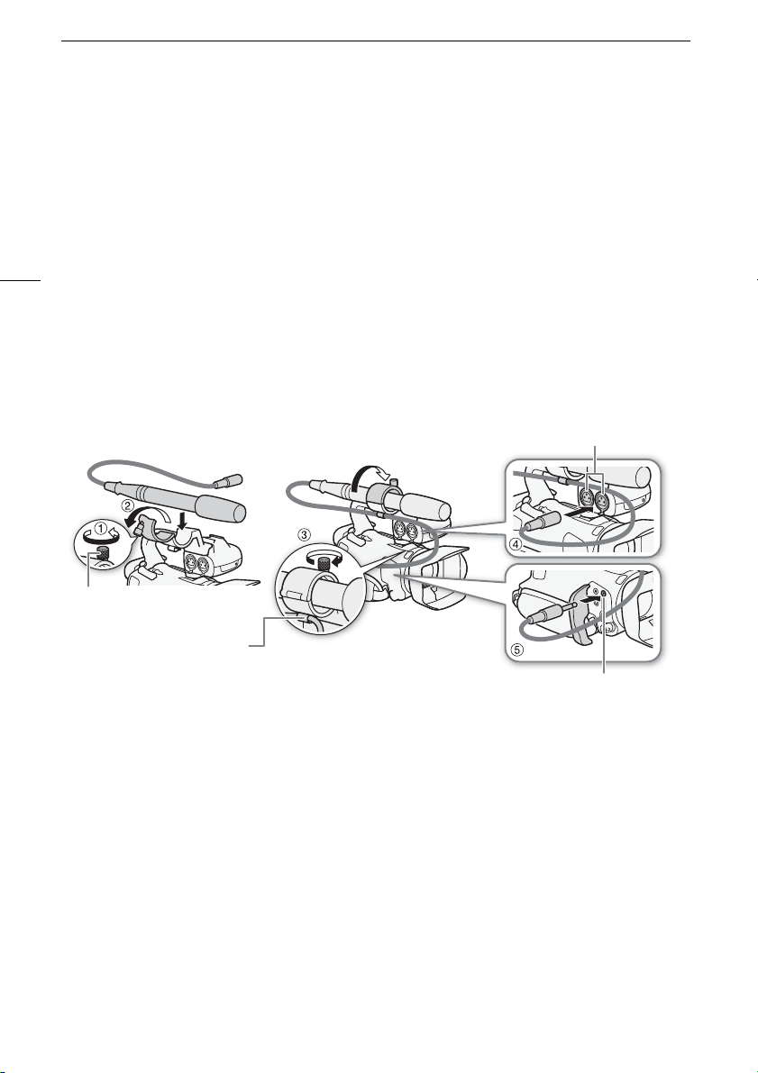
Recording Audio
Microphone lock screw
Cable clamp
INPUT 1/INPUT 2 terminals
MIC terminal
Connecting an External Microphone or External Audio Input Source to the
Camcorder
To each of the INPUT terminals you can attach commercially available microphones or analog line-in
sources with an XLR connector. To use the INPUT terminals and microphone holder, the handle unit
must be correctly attached to the camcorder. To the MIC terminal you can attach commercially
available condenser microphones with their own power supply, and a 3.5 mm stereo mini plug.
Follow the procedure below to attach a microphone (refer also to the following illustration). To connect
70
an external device to the camcorder, plug the device’s cable into the desired INPUT terminal (햵).
1 Loosen the microphone lock screw (햲), open the microphone holder and insert the
microphone (햳).
2 Tighten the lock screw and put the microphone cable through the microphone cable
clamp under the microphone holder (햴).
3 Plug the microphone or external device's cable into the desired INPUT terminal (햵) or the
MIC terminal (햶).
Page 71
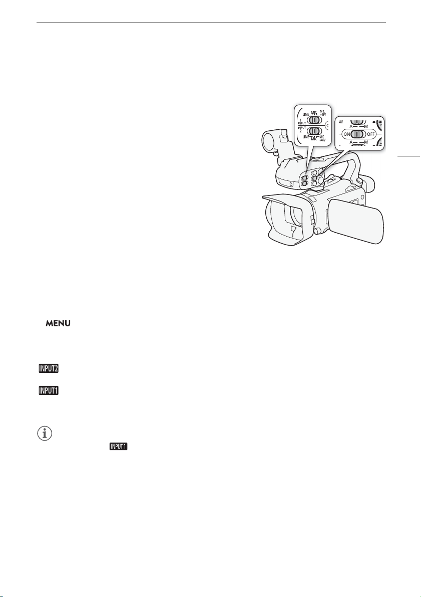
Recording Audio
NOTES
Using Line Input or an External Microphone Connected to an INPUT
Te rm i na l
1 Set the INPUT terminal ON/OFF switch to ON.
2 Set the sensitivity selection switches for INPUT 1/
INPUT 2 to LINE or MIC.
• To supply a microphone with phantom power, set the
switch to MIC+48V instead. Make sure to connect the
microphone first, before turning the phantom power on.
Keep the microphone connected when turning off the
phantom power.
To record the same audio input to two audio channels
By default, when using the INPUT terminals, each audio input is recorded to a separate audio channel
(INPUT 1 to CH1 and INPUT 2 to CH2). If necessary (for example, as an audio backup recording), you
can record the audio input into the INPUT 1 terminal to both audio channels, CH1 and CH2. In that
case, you can adjust the audio recording levels of each channel independently of each other.
1 Select [CH2 Input].
> [C ! Audio Setup] > [CH2 Input]
2 Select the desired option and then select [X].
71
Options
[ INPUT 2]: Records audio to each channel separately. Audio input into INPUT 1 is recorded to
CH1, while audio input into INPUT 2 is recorded to CH2.
[ INPUT 1]: Audio input into INPUT 1 is recorded to both channels. Audio input into INPUT 2
will not be recorded.
• Even if you select [ INPUT 1], the audio recording level for channel 2 will be determined by the
audio level switch and dial for INPUT 2.
Page 72
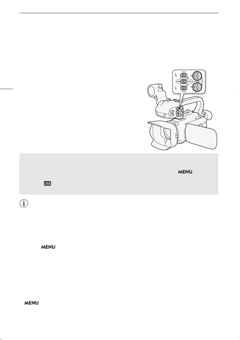
Recording Audio
NOTES
Audio Recording Level (INPUT Terminals)
You can set the audio recording level to automatic or manual independently for each channel.
Furthermore, when you adjust the audio recording level manually, you can set the level (from –G to
18 dB) independently for each channel, as well.
1 Set the audio level switch of the desired channel to A
(automatic) or M (manual).
72
• If you set the switch to A, the audio level will be adjusted
automatically and you do not need to perform the rest of
the procedure. If you set the switch to M, continue the
procedure to set the audio recording level.
2 Turn the corresponding audio level dial.
• For reference, MIN corresponds to –G, the larger mark in
the middle of the scale corresponds to 0 dB, and MAX
corresponds to +18 dB.
• As a guideline, adjust the audio recording level so that the
audio level meter will go to the right of the –18 dB mark (one
mark right of the –20 dB mark) only occasionally.
Automatic Level Control (ALC) for CH1 and CH2 of the INPUT terminals
When the INPUT 1 and INPUT 2 switches are both set to the same type of audio source (line input
or microphone), you can link the audio level adjustment for both inputs with the >
[C Audio Setup] > [INPUT 1/2 ALC Link] setting.
When the [ Linked] option is selected, you can adjust both audio channels with the CH1 audio
level switch and CH1 audio level dial.
• When the audio level meter reaches the red point (0 dB), the sound may be distorted.
• If the audio level meter display is normal but the sound is distorted, activate the microphone's
attenuator (A 73).
• We recommend using headphones to check the sound level while adjusting the audio recording
level or when the microphone attenuator is activated.
• If at least one of the channels is set to manual adjustment, you can activate the audio peak limiter
with the > [¡ Audio Setup] > [INPUT 1/2 Limiter] setting. When activated, æ appears
on the screen and the audio peak limiter will limit the amplitude of audio input signals when those
signals start to distort.
Adjusting the Microphone’s Sensitivity (INPUT terminals)
When one of the audio channels is set to the INPUT terminals and the corresponding sensitivity
selection switch is set to MIC or MIC+48V, you can select the external microphone’s sensitivity.
1 Select the desired INPUT terminal’s sensitivity.
> [C ! Audio Setup] > [INPUT 1 Mic Trimming] or [INPUT 2 Mic Trimming]
2 Select the desired option and then select [X].
• You can select one of 5 sensitivity levels from –12 dB to +12 dB.
Page 73
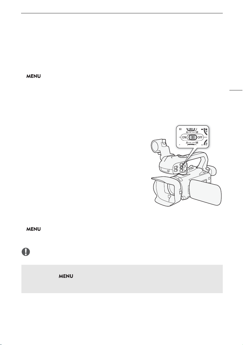
Recording Audio
IMPORTANT
Adjusting the L and R channels of the MIC terminal independently
You can use the > [¡ Audio Setup] > [MIC ALC Link] setting to separate the audio
level adjustment for the L and R channels of an external microphone connected to the MIC
terminal, allowing each channel to be adjusted independently.
Microphone Attenuator (INPUT terminals)
When one of the audio channels is set to the INPUT terminals and the corresponding sensitivity
selection switch is set to MIC or MIC+48V, you can activate the external microphone’s attenuator
(20 dB).
1 Select the desired INPUT terminal’s sensitivity.
> [C ! Audio Setup] > [INPUT 1 Mic Att.] or [INPUT 2 Mic Att.]
2 Select [i On] and then select [X].
• å appears at the right of the screen.
Using the Built-in Microphone or an External Microphone Connected to the
MIC Terminal
If the handle unit is attached to the camcorder but you will not
connect an external microphone to an INPUT terminal, follow the
step below to use the built-in microphone or an external
microphone connected to the MIC terminal. When an external
microphone is connected to the MIC terminal, the camcorder will
switch automatically from the built-in microphone to the external
one.
Set the INPUT terminal ON/OFF switch to OFF.
• If you connect a microphone to the MIC terminal, the
camcorder will switch automatically from the built-in
microphone to the external microphone.
73
To use a commercially available plug-in power microphone
1 Select [MIC Power].
> [¡ # Audio Setup] > [MIC Power]
2 Select [i On] and then select [X].
• Supplying power to a microphone without plug-in power functionality may damage the microphone.
Page 74
Recording Audio
NOTES
Audio Recording Level (Built-in Microphone/MIC Terminal)
You can adjust the audio recording level of the built-in microphone or an external microphone
connected to the MIC terminal.
1 Open the audio screen.
[FUNC] > [C Audio]
2 Select [CH1/2] or [CH3/4] as necessary, to change the pair of audio channels you wish to adjust.
74
•When > [C Audio Setup] > [MIC ALC Link] is set to [ Separated], select the audio
channel to adjust and repeat steps 2 to 4 for the other audio channel if necessary.
3 Select [ Automatic] or [ö Manual].
• If you selected automatic adjustment, skip to step 5. If you selected manual adjustment, continue
the procedure to adjust the audio recording level.
4Touch and hold [Ï] or [Ð] to adjust the recording level as necessary.
• As a guideline, adjust the audio recording level so that the audio level meter on the screen will go
to the right of the –18 dB mark (one mark right of the –20 dB mark) only occasionally.
5Select [X].
• When the audio level meter reaches the red point (0 dB), the sound may be distorted.
• If the audio level meter display is normal but the sound is distorted, activate the microphone's
attenuator (A 73).
• We recommend using headphones to check the sound level while adjusting the audio recording
level or when the microphone attenuator is activated.
Microphone Sensitivity (Built-in Microphone)
You can increase the built-in microphone’s sensitivity.
1 Select [Built-in Mic Sensitivity].
> [C " Audio Setup] > [Built-in Mic Sensitivity]
2 Select the desired option and then select [X].
Options
[h Normal]: For recording audio under usual conditions.
[ High]: For recording audio at a higher level (+6 db).
Page 75

Recording Audio
Microphone Attenuator (Built-in Microphone or MIC Terminal)
If the audio level is too high and the audio sounds distorted while recording with the built-in
microphone or external microphone (MIC terminal), activate the microphone attenuator (20 dB) for the
respective microphone.
1 Select [Built-in Mic Att.] or [MIC Att.].
> [C
2 Select the desired option and then select [X].
! Audio Setup] > [Built-in Mic Att.] or [MIC Att.]
Options
[2 Automatic]: The camcorder will automatically activate the microphone attenuator as necessary
[i On]: The microphone attenuator will be activated at all times to reproduce more
[j Off]: The microphone attenuator will be deactivated at all times. will appear on the
for optimal audio recording levels so high audio levels will not be distorted.
faithfully the sound dynamics. å will appear on the screen.
screen.
Low-Cut Filter (Built-in Microphone or MIC Terminal)
You can activate the low cut filter to reduce the sound of blowing wind, a car’s engine and similar
ambient sounds. When recording in surroundings unaffected by wind or if you want to record lowfrequency sounds, we recommend turning off the low-cut filter.
1 Select [Built-in Mic Low Cut] or [MIC Low Cut].
> [C ! Audio Setup] > [Built-in Mic Low Cut] or [MIC Low Cut]
2 Select [i On] and then select [X].
75
Page 76
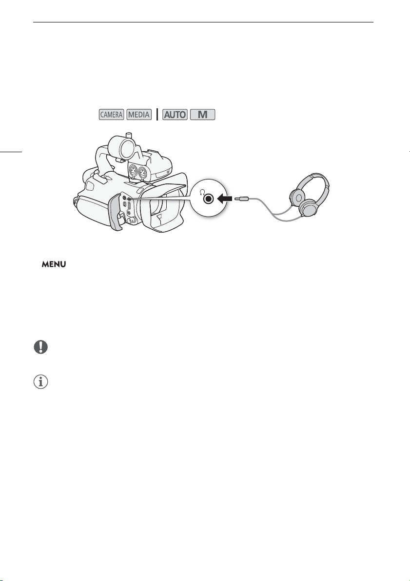
Using Headphones
IMPORTANT
NOTES
Using Headphones
Use headphones for playback or to check the audio level while recording. The following procedure
explains how to adjust the volume.
Operating modes:
76
1 Select [Headphone Volume].
> [C # Audio Setup] > [Headphone Volume]
2 Select [Ô] or [Õ] to adjust the volume and then select [X].
• You can also drag your finger along the volume bar.
To adjust the volume during playback
During playback, adjust the headphones volume the same way you adjust the speaker’s volume
(A 91).
• When using headphones, make sure to lower the volume to an appropriate level.
• Use commercially available headphones with a 3.5 mm minijack.
Page 77
Color Bars/Audio Reference Signal
NOTES
Color Bars/Audio Reference Signal
You can have the camcorder output and record color bars and a 1 kHz audio reference signal and
output them from the HDMI OUT terminal, SDI OUT terminal (s only) and × (headphone)
terminal (audio reference signal only).
Operating modes:
Recording Color Bars
You can choose between SMPTE and ARIB color bars.
1 Select [Color Bars].
> [3 # Recording Setup] > [Color Bars]
2 Select the desired option and then select [X].
• The selected color bars appear on the screen and will be recorded when you press the START/
STOP button.
• This function cannot be used together with slow & fast motion recording.
Recording an Audio Reference Signal
The camcorder can output a 1 kHz audio reference signal with the color bars.
1 Select [1 kHz Tone].
> [3 # Recording Setup] > [1 kHz Tone]
2 Select the desired option and then select [X].
• You can select one of three audio levels (–12 dB, –18 dB, –20 dB) or select [j Off] to turn off
the signal.
• The signal is output at the selected level and will be recorded when you press the START/STOP
button.
77
Page 78
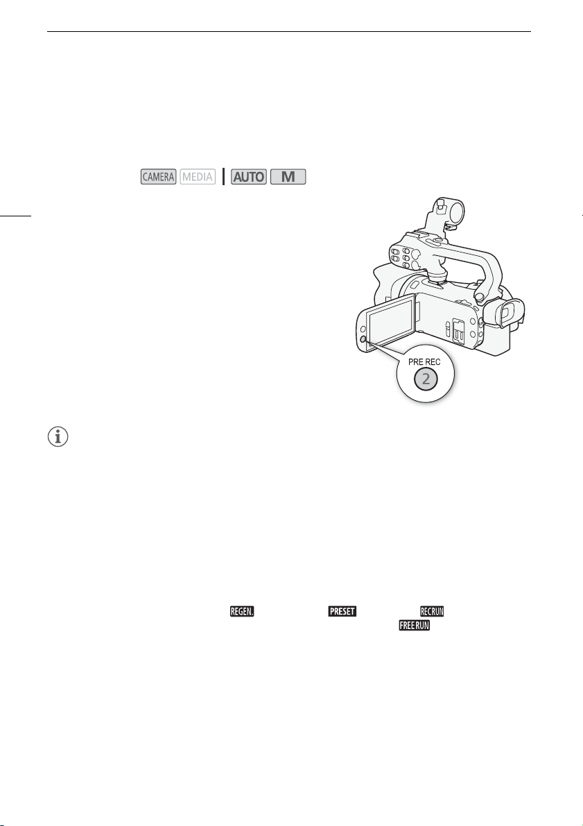
Pre-Recording
NOTES
Pre-Recording
When pre-recording is activated, the camcorder starts recording continuously into a temporary
memory (approx. 3 seconds) so when you press the START/STOP button, the clip will contain also a
few seconds of video and audio recorded before you pressed the button.
Operating modes:
78
1 Press the PRE REC button.
• Pre-recording is activated and z appears at the top of the
screen.
• Press the button again to turn off pre-recording.
2 Press the START/STOP button.
• The clip recorded on the card will include a few seconds of
video and audio recorded before the START/STOP button
was pressed.
• The camcorder will not record the full 3 seconds prior to pressing the START/STOP button if the
button was pressed within 3 seconds of having turned on pre-recording or having finished the
previous recording.
• This function cannot be used together with slow & fast motion recording.
• Pre-recording will be deactivated in the following cases:
- When the power switch or camera mode switch is operated.
- When a menu is opened.
- When the shooting mode, white balance or look is changed.
- When the SD card compartment cover is opened or the SD card being recorded to becomes full.
• About the time code when pre-recording is activated:
- The time code of the clip will start a few seconds before the START/STOP button was pressed.
- If the time code mode was set to [ Regen.], or to [ Preset] with [ Rec Run] running
mode, the time code running mode will be changed automatically to [ Free Run] when prerecording is activated.
- When pre-recording is turned off, the time code running mode will return to its previous setting.
Page 79
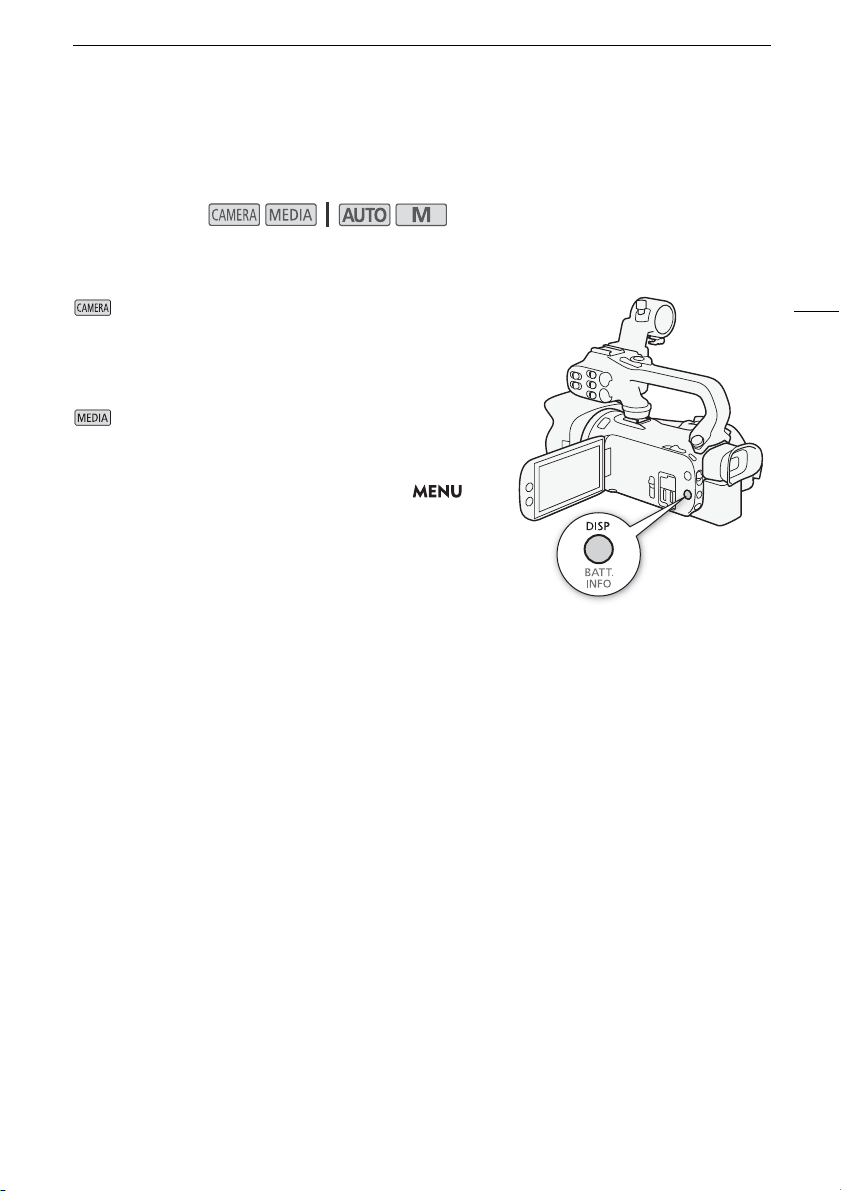
Onscreen Displays
Onscreen Displays
You can turn most onscreen displays on or off.
Operating modes:
Repeatedly press the DISP button to turn the onscreen displays on/off in the following
sequence:
mode:
• All displays on
• Onscreen markers
•Displays off
2
mode
•Only data code on
• All displays on
1
The onscreen markers will be displayed only when >
[£ Display Setup] > [Onscreen Markers] is set to an option
other than [j Off].
2
Pressing the DISP button has the same effect as touching the
screen. During single photo view and while playing back a clip, the
playback controls are displayed only momentarily.
1
:
79
Page 80
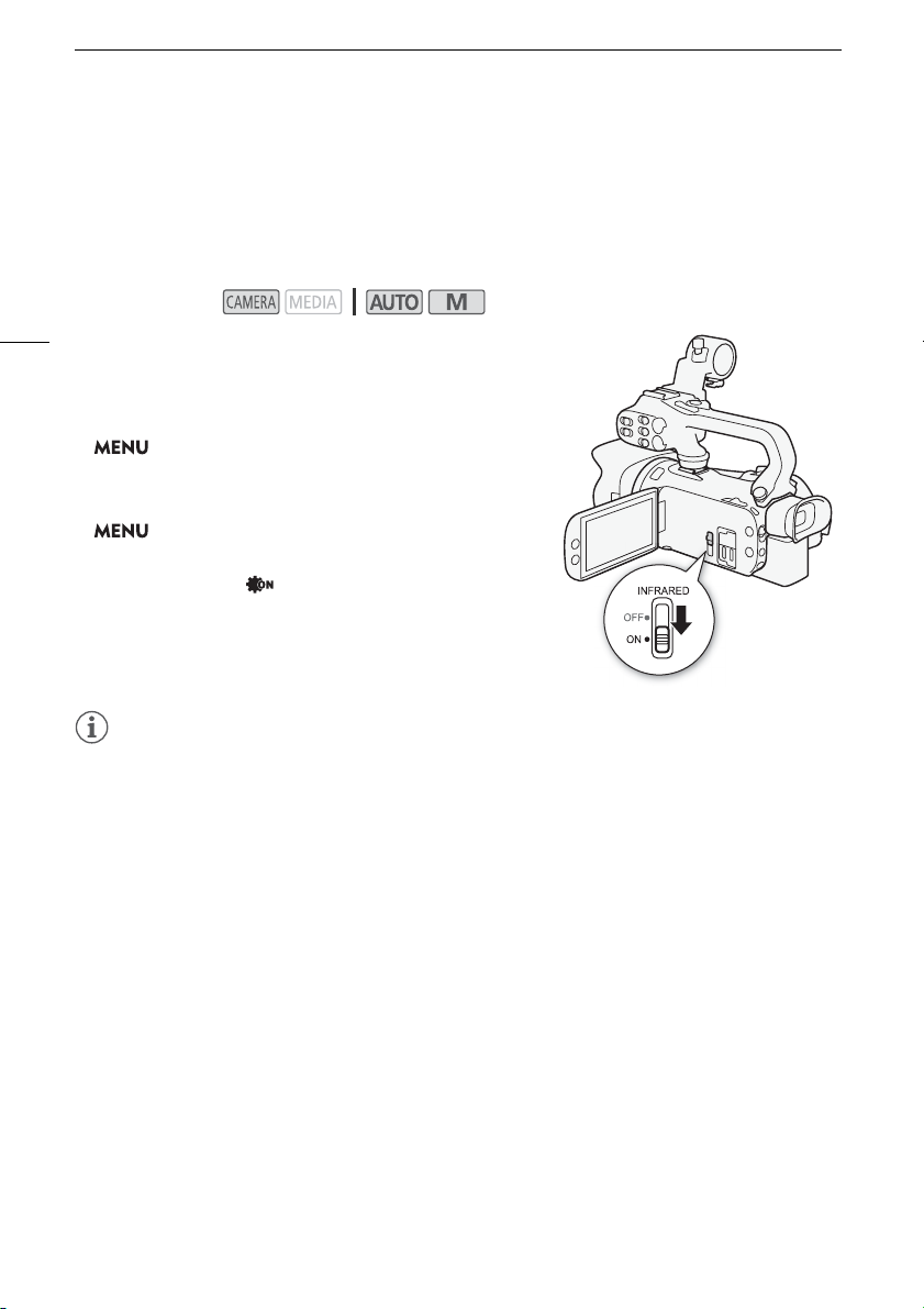
Infrared Recording
NOTES
Infrared Recording
Using the infrared mode, the camcorder becomes more sensitive to infrared light, allowing you to
record in dark locations. You can also use the handle unit's infrared light to keep shooting even in very
dark conditions. Also, you can select whether the brighter areas of the picture appear in green or
white.
Operating modes:
80
1 Set the INFRARED switch to ON.
• ; and = appear at the top left of the screen.
2 To change the color of highlights in the infrared picture,
select [IR Rec Color].
> [v % Camera Setup] > [IR Rec Color]
3 Select [± White] or [² Green] and then select [X].
4 To turn on the infrared light, select [IR Light].
> [v $ Camera Setup] > [IR Light]
5 Select [i On] and then select [X].
• = changes to .
• While infrared mode is activated, the following apply.
- The aperture remains fully open and the ND filter remains retracted. Additionally, the camcorder
switches to automatic shutter speed and gain.
- Exposure adjustment, AGC limit, backlight correction (both automatic and constant) and face
detection & tracking are deactivated.
- The camcorder switches to autofocus initially but you can change the focus mode to manual
focus. The focusing distance display is grayed out.
- The white balance switches to a setting for infrared mode.
- The shooting mode and looks cannot be set.
• Depending on the light source, autofocus may not work well while zooming.
• In infrared mode the camcorder's sensor is considerably more sensitive to near-infrared light. Do not
point the lens at strong light or heat sources when infrared recording is activated. If there are such
light/heat sources in the picture, be sure to shield the lens before switching the camcorder to
infrared mode.
• If you set an assignable button to [< IR Light] (A 85), you can press the button to turn the infrared
light on/off.
Page 81
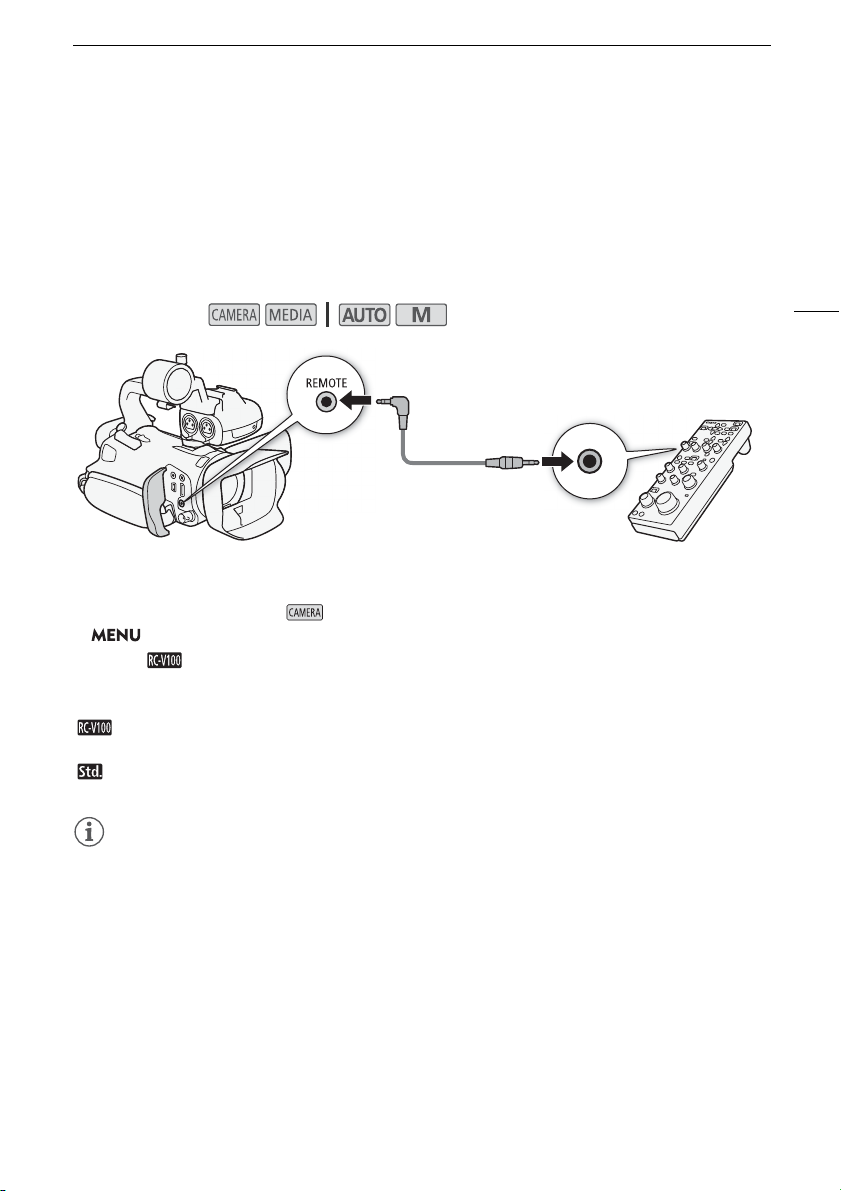
Using the Optional RC-V100 Remote Controller
NOTES
Remote cable
(supplied with the RC-V100)
To the RC-V100’s
REMOTE A terminal
- CANCEL button
-ND button
-AGC button
- AUTO KNEE button
- BLACK GAMMA LEVEL dial
- WHITE BALANCE R and B dials
- MASTER PEDESTAL dial
-AUTO IRIS button
- SHUTTER SELECT button
- CUSTOM PICT. button
- KNEE POINT, KNEE SLOPE dials
- SHARPNESS LEVEL dial
- MASTER BLACK R and B dials
Using the Optional RC-V100 Remote Controller
You can connect the optional RC-V100 Remote Controller to the camcorder’s REMOTE terminal in
order to control the camcorder (including advanced recording functions) from a distance. The remote
controller lets you turn the camcorder on, navigate the menus and remotely control the aperture and
shutter speed, and more.
Use the cable supplied with the remote controller to connect it to the camcorder. For details on how to
connect and use the remote controller, refer to its instruction manual.
Operating modes:
1 Turn off the camcorder and connect the optional RC-V100 Remote Controller to the
camcorder.
2 Turn on the camcorder in mode and select [REMOTE Terminal].
> [B " System Setup] > [REMOTE Terminal]
3 Select [ RC-V100 (REMOTE A)] and then select [X].
81
Options
[ RC-V100 (REMOTE A)]:
Select this option to use the optional RC-V100 Remote Controller.
[ Standard]: Select this option to use commercially available remote controls.
• The following controls on the remote controller will not operate the camcorder:
Page 82
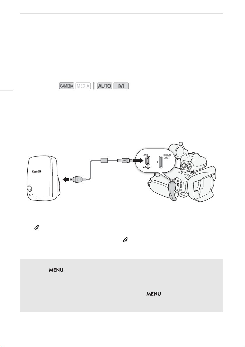
Using the GP-E2 GPS Receiver
To adjust the date and time automatically according to the GPS data
You can set > [B System Setup] > [GPS Auto Time Setting] to [i Auto Update], to
have the camcorder automatically adjust its date and time settings according to the information
received from the GPS signal. The date and time will be updated automatically the first time a
correct GPS signal is acquired after turning on the camcorder.
• While the automatic date/time adjustment is activated, the > [B System Setup] >
[Date/Time] setting will not be available.
• The time will not be updated while recording.
Using the GP-E2 GPS Receiver
When the optional GP-E2 GPS Receiver is connected to the camcorder's USB terminal, the
camcorder will automatically record the GPS information (longitude, latitude and altitude) and the UTC
(coordinated universal time) date and time to every recording you make (clips and photos). The
recorded GPS information can be checked on the clip information screen or photo playback screen
(single photo view).
82
Operating modes:
Connecting the GPS Receiver
Turn off the camcorder and the receiver. Connect the receiver to the camcorder’s USB terminal using
the USB cable*. While recording, place the receiver in the carrying case* and attach it to the
camcorder’s grip belt or carry it on your person. For details about connecting and using the receiver,
refer to the GP-E2 Instruction Manual.
* Supplied with the optional GP-E2 GPS Receiver.
Activating the GPS Receiver
Turn on the camcorder and receiver.
• The icon appears on the left of the screen and will blink as the receiver tries to acquire satellite
signals.
• When satellite signals are correctly acquired, the icon will stay continuously on. GPS functions
will be activated, and clips and photos recorded thereafter will be geotagged.
Page 83

Using the GP-E2 GPS Receiver
IMPORTANT
NOTES
• In certain countries/regions, the use of GPS may be restricted. Be sure to use the GPS receiver in
accordance with local laws and regulations of the country/region where the receiver is used. Be
particularly careful when traveling outside of your home country.
• Be careful about using the GPS receiver in places where the use of electronic devices is restricted.
• The GPS information recorded with clips and photos may contain data that can lead others to
locate or identify you. Be careful when sharing geotagged recordings with others or when uploading
them to the Web.
• Do not leave the GPS receiver near strong electromagnetic fields such as near powerful magnets
and motors.
• The GPS information recorded with clips corresponds to the location at the start of the recording.
• Do not place cables connected to the SDI OUT terminal (s only) or HDMI OUT terminal near
the receiver. Doing so may negatively affect the GPS signal.
• Initial GPS signal reception will take longer after replacing the receiver’s battery or when first turning
on the receiver after a prolonged period of having been turned off.
• The camcorder is not compatible with the receiver's digital compass and positioning interval
functions. Also, the [Set Now] option is not available for the [GPS Auto Time Setting] setting.
83
Page 84
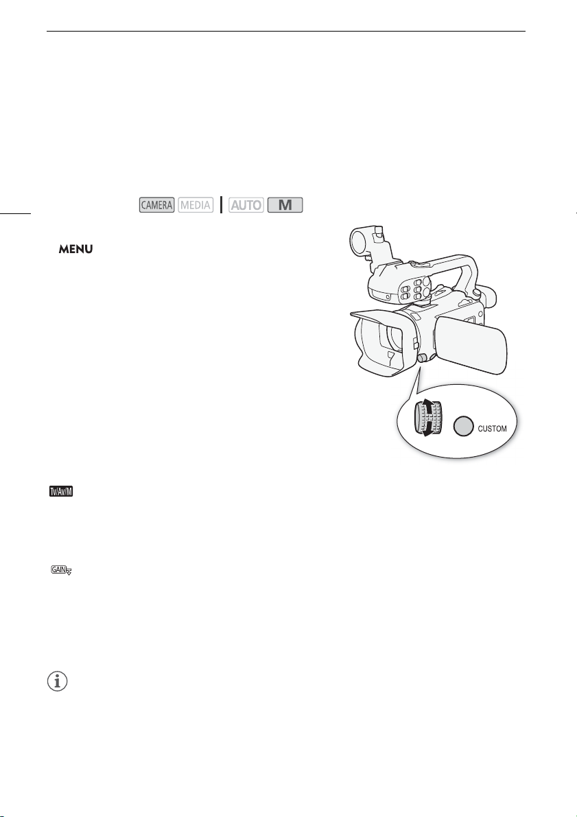
CUSTOM Dial and Button
NOTES
Customization
4
Customization
CUSTOM Dial and Button
You can assign to the CUSTOM button and dial one of several frequently used functions. You can then
adjust the selected function using the CUSTOM button and dial, without having to access the menu.
84
Operating modes:
1 Select [CUSTOM Dial & Button].
> [B # System Setup] > [CUSTOM Dial &
Button]
2 Select the desired option and then select [X].
3 Press the CUSTOM button and turn the CUSTOM dial
to use the assigned function as described in the
following explanations.
• The onscreen value that can be adjusted using the
CUSTOM dial will be highlighted in orange.
Options
[ Tv/Av/M]: When the shooting mode is set to ‚ or “, turn the CUSTOM dial to adjust the
shutter speed or aperture value, respectively.
When the shooting mode is set to n, press the CUSTOM button repeatedly to
select the value you wish to adjust (aperture value shutter speed gain value).
While the desired value is highlighted in orange, turn the dial to adjust it.
[ AGC Limit]: Press the CUSTOM button to turn the AGC limit on/off. When the AGC limit is
activated, turn the dial to set the maximum gain value.
[y Exposure Comp.]:
Press the CUSTOM button to lock the exposure. Whether the exposure is locked
or not, you can turn the dial to compensate the exposure.
[j Off]: Disables the CUSTOM button and dial.
• Instead of the procedure above, you can press and hold the CUSTOM button to display a quick
menu of the options. Use the CUSTOM dial to select the desired option and then press the
CUSTOM button.
Page 85
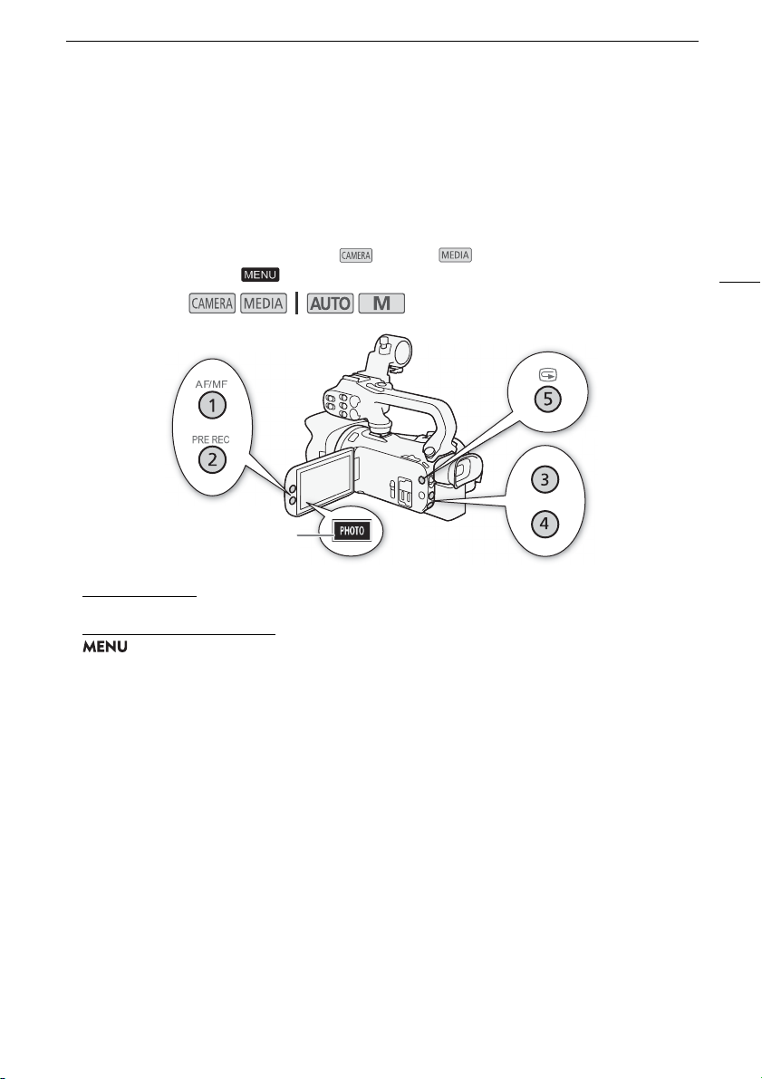
Assignable Buttons
Onscreen
assignable button
Assignable Buttons
The camcorder offers 5 assignable buttons on the camcorder's body and an onscreen button (touch
operation) to which you can assign various functions (assignable buttons). Assign often-used functions
to the buttons you find most convenient, to personalize the camcorder to your needs and preferences.
The names of the buttons printed on the camcorder also indicate their default settings. The onscreen
assignable button will show only the icon of the function currently assigned to it.
Assigned functions can be changed only in mode. In mode, only a button with
[œ Monitor Channels] or [ Menu] assigned to it can be used.
Operating modes:
85
1 Physical buttons: Press the MENU button and, while holding it pressed down, press the
assignable button whose function you wish to change.
Onscreen assignable button
> [B # System Setup] > [Onscreen Assignable Button]
• A list of available functions appears with the current function assigned to the button highlighted.
• You can use the menu also for physical assignable buttons. The corresponding settings
([Assignable Button 1] to [Assignable Button 5]) can be found under page " in the [B System
Setup] menu.
: Open the function selection screen with the menu setting.
2 Select the desired function and then select [X].
• If necessary, select [Í]/[Î] to scroll up/down.
3 Press the assignable button (or touch the onscreen assignable button) to use the assigned
function as described in the following table.
Page 86
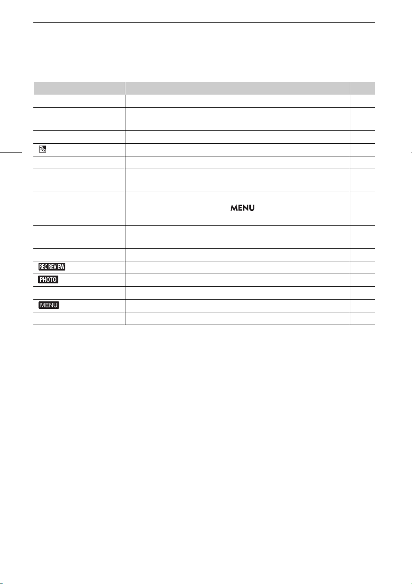
Assignable Buttons
Assignable functions
Function name Description A
[B AF/MF] Switches between autofocus and manual focus. 57
[~ Face Only AF] Switches between standard autofocus and autofocus only when a face is
detected.
[^ Magnification] Turns magnification on/off. 59
86
[ BLC Always On] Turns the constant backlight correction function on/off. 47
[± Powered IS] Turns powered IS on/off. 63
[Å Set WB] Registers a custom white balance setting. This is not available for the
onscreen assignable button.
[Ä WB Priority] Switches between the current white balance setting and a priority white
balance setting registered with the > [v Camera Setup] >
[Set WB Priority] setting.
[< IR Light]* When infrared recording is activated, turns the camcorder's infrared light
on/off.
[z Pre REC] Turns pre-recording on/off. 78
[ Rec Review] Reviews the last clip recorded. 36
[ Photo] Records a photo. 34
[œ Monitor Channels] Changes the audio channels output from the × (headphone) terminal. 99
[ Menu] Displays/Hides the menu. 102
[j Off] No function assigned – the button is disabled. —
* Requires that the handle unit be correctly attached to the camcorder.
62
49
103
80
Page 87

Saving and Loading Menu Settings
Saving and Loading Menu Settings
After you adjust settings in the various menus, you can save those settings on an SD card. You can
load those settings at a later date or on another XA45 / XA40 camcorder so that you can use that
camcorder in a similar way.
Camcorder settings can only be saved on or loaded from the SD card in card slot B.
Operating modes:
Saving Camcorder Settings
1 Insert the SD card where you want to save the camcorder's settings into SD card slot B.
2 Select [Save].
> [B # System Setup] > [Backup Menu Settings 7] > [Save]
3 Select [Yes].
• The camcorder’s menu settings will be saved to the card. If menu settings were previously saved,
the old file will be overwritten by the current menu settings.
4 When the confirmation message appears, select [OK].
Loading Camcorder Settings
1 Insert an SD card that contains previously saved camcorder settings into SD card slot B.
2 Select [Load].
> [B # System Setup] > [Backup Menu Settings 7] > [Load]
3 Select [Yes].
• The camcorder’s menu settings will be replaced by the settings saved on the card. Then, the
screen will turn black momentarily and the camcorder will restart.
87
Page 88
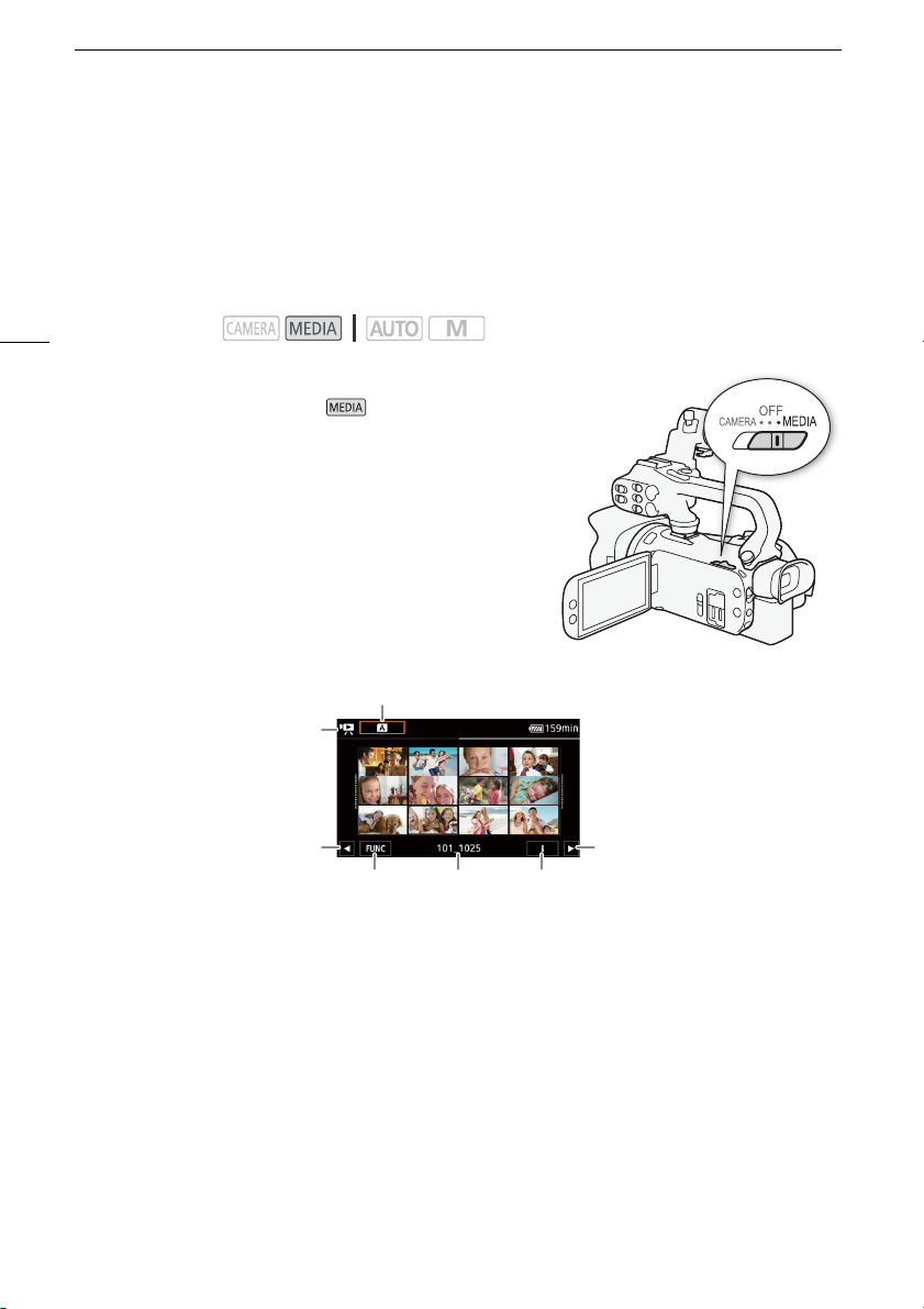
Basic Playback
3
456
1
22
1 y: Clip index screen
}: Photo index screen.
2 Display the next/previous index page.
You can also swipe left/right on the screen.
3 Index screen button: Select to change the
index screen. Select the desired
combination of card (6 or 7) and type of
recording (y¸ clips or } photos) you
want to play back.
4 [FUNC] button: Clip/photo operations
(A 92).
5 Folder name. The last 4 digits indicate the
recording date (1025 = October 25)
(A 107).
6 Clips only: Clip information (A 91).
Playback
5
Playback
Basic Playback
This section explains how to play back clips and photos. For details on playing back recordings using
an external monitor, refer to
88
Operating modes:
1 Set the power switch to MEDIA.
• The camcorder switches to mode and the clip index
screen appears.
2 Look for the clip or photo you wish to play back.
• Swipe left/right or select [Ï]/[Ð] to check other index
pages.
• To view photos or play back recordings on the other SD
card, change the index screen.
Connecting to an External Monitor
(A 96).
3 In the index screen, select the thumbnail of the desired recording.
• Clips: Playback will start from the selected clip until the last clip in the index screen.
Photos: The selected photo will be displayed. Swipe left/right to view other photos.
Page 89
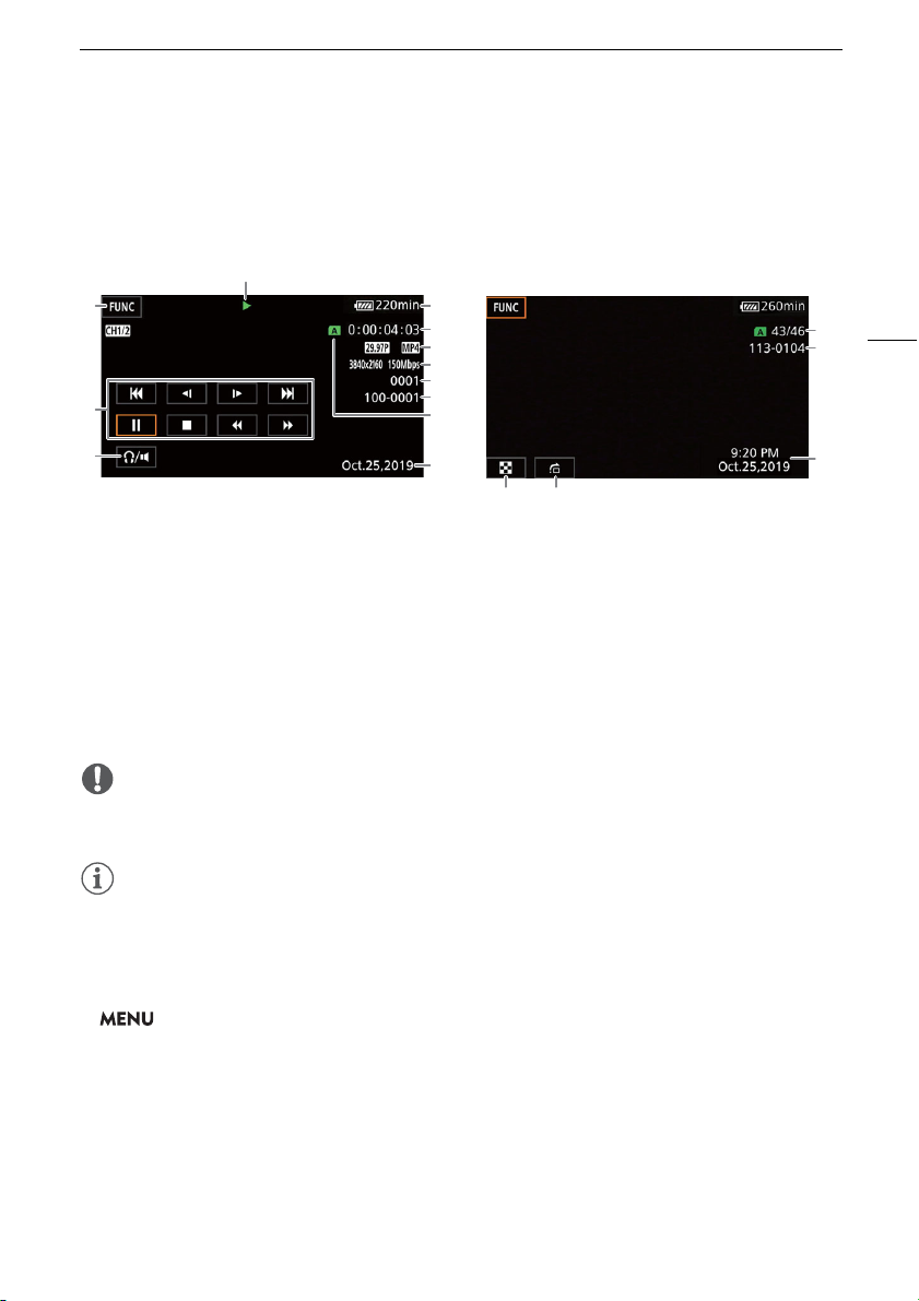
Basic Playback
IMPORTANT
NOTES
1 5
6
7
8
9
10
11
12
2
3
4
9
10
12
13 14
1 [FUNC] button: Clip/photo operations
(A 92)
2 Clip playback controls (A 90)
3Volume (A 91)
4 Clip playback operation (A 90)
5 Remaining battery charge (A 113)
6 Time code (A 64)
7 Frame rate (A 37) and movie format
8 Resolution and bit rate (A 37)
9 Clips: Clip number
Photos: Photo number / Total number of
photos
10 File number (A 107)
11 SD card selected for playback (A 88)
12 Data code (A 105)
13 Return the photo index screen
14 Photo jump (A 90)
4 Touch the screen to display the playback controls.
• During video or photo playback, the playback controls will disappear automatically after a few
seconds. In video playback pause, touch the screen again to hide the playback controls.
• For details on the playback controls, refer to
Playback Controls
(A 90).
89
• You may not be able to play back with this camcorder clips recorded on an SD card using another
device.
• The following image files may not be displayed correctly.
- Images not recorded with this camcorder.
- Images edited on a computer.
- Images whose file names have been changed.
• You can turn off the recording date and time display or change the information displayed with the
• Depending on the recording conditions, you may notice brief stops in video or sound playback
> [É Playback Setup] > [Data Code] setting. Note that available options depend on the
type of recording.
between clips.
Page 90
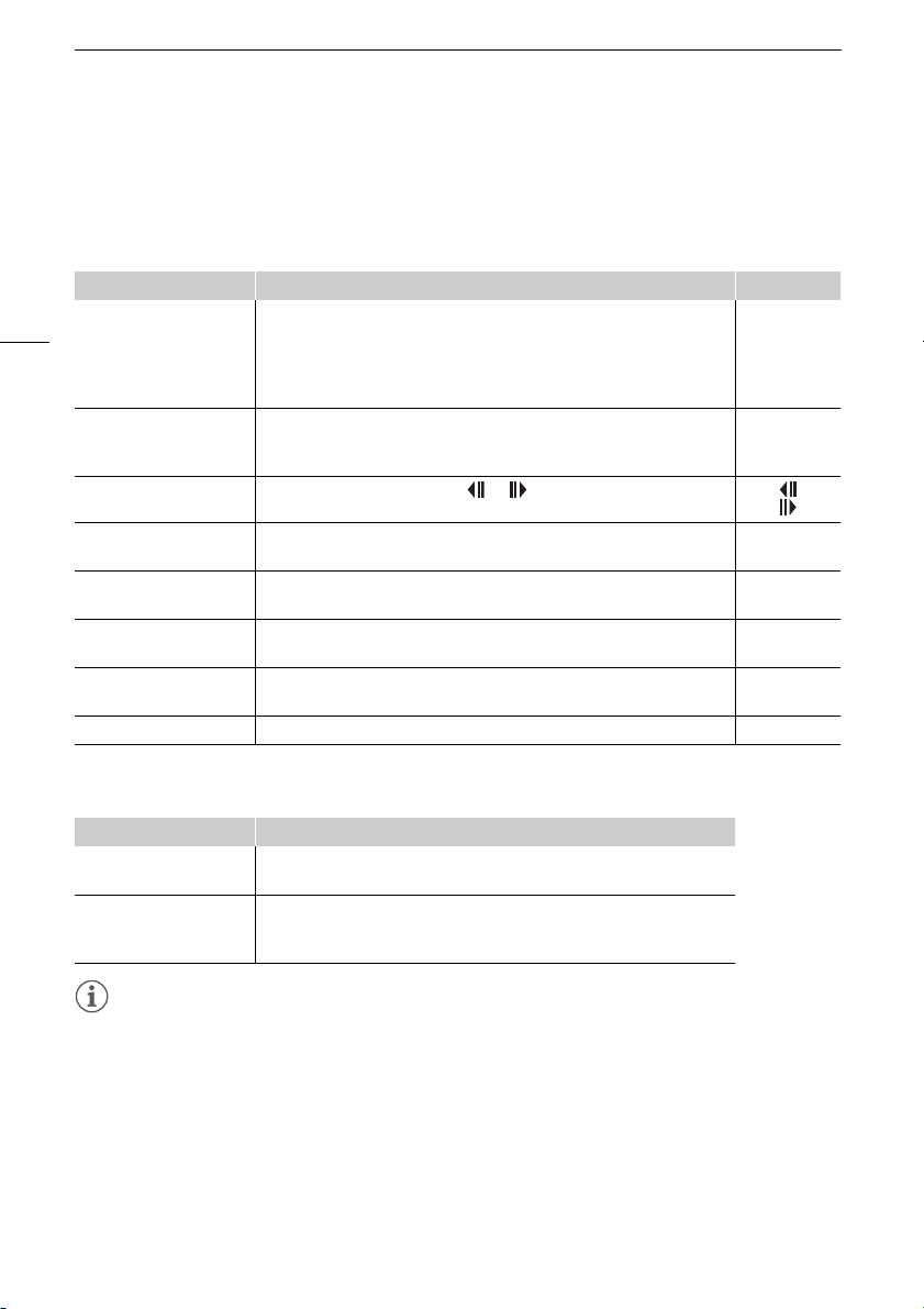
Basic Playback
NOTES
Playback Controls
The following playback types are available using the onscreen controls. Using the joystick, push the
joystick to select the desired button and then press the joystick.
Clip playback controls
Playback type Operation Onscreen icon
Fast playback* During playback, select [Ø] / [×].
90
Slow playback* Select [Ö] / [Õ].
Frame reverse/advance* During playback pause, select [ ] / [ ].
• Select repeatedly to increase the playback speed to approximately 5x
15x 60x the normal speed.
• During fast playback, select [Ð] to return to playback at normal
speed.
• Touch repeatedly to change the playback speed to approximately 1/4
1/8 the normal speed.
x00×
Øx00
x1/0Õ
Öx1/0
Skip to the beginning of
the current clip
Skip to the beginning of
the previous clip
Skip to the beginning of
the next clip
Pause/resume playback During playback, select [Ý] to pause.
Stop playback Select [Ñ] to stop playback and return to the index screen. —
* There is no audio during this playback mode.
Photo playback controls
Playback type Operation
Return to the photo index
screen
Photo jump Select [h] to display the scroll bar. Select [Ï] / [Ð], or drag your
• During fast/slow playback, you may notice some anomalies (blocky video artifacts, banding, etc.) in
the playback picture.
• The speed indicated on the screen is approximate.
• Slow reverse playback will look the same as continuous frame reverse.
Select [Ú].
Select [Ú] twice.
Select [Ù].
During playback pause, select to [Ð] to resume normal playback.
Select [f].
finger along the scroll bar, to find the desired photo. Select [L] to
return to single photo view.
—
—
—
Ý
Ð
Page 91
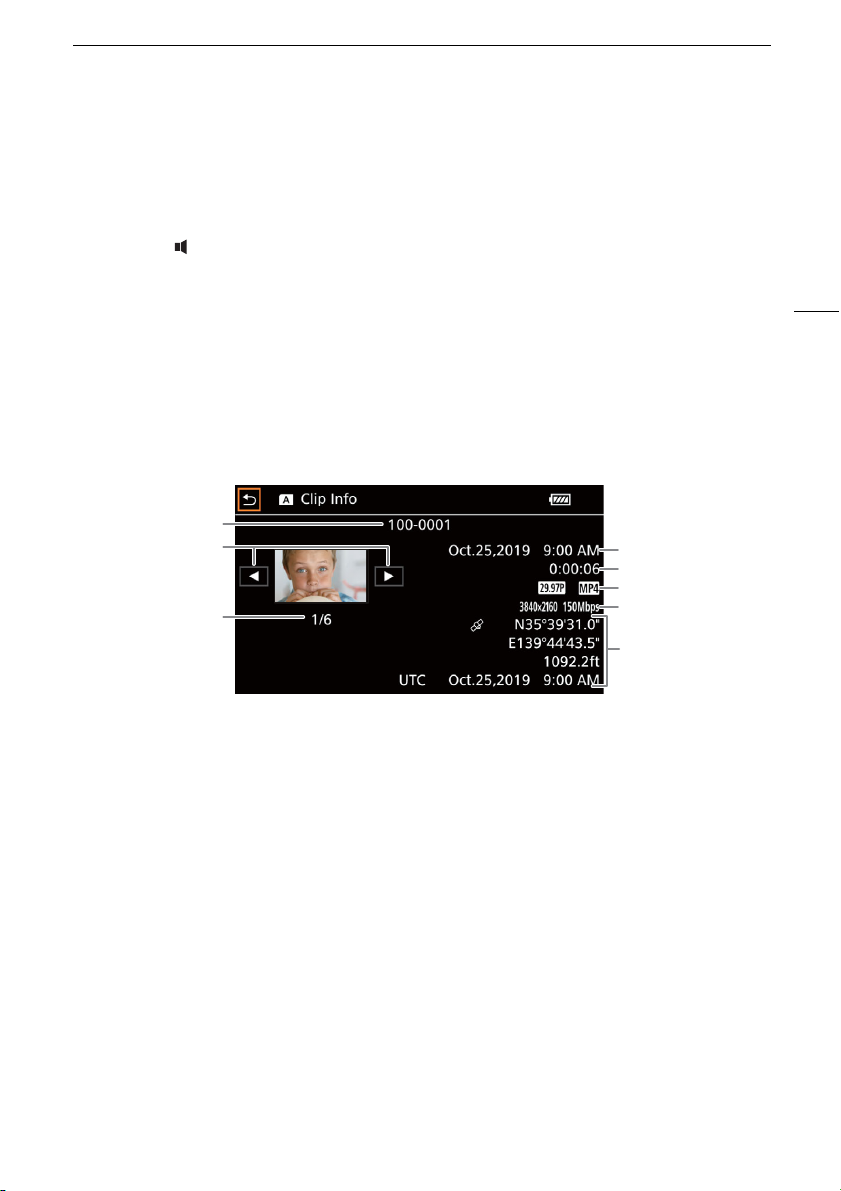
Basic Playback
1 File number (A 107)
2 Display the information for the previous/next
clip
3Clip number / Total number of clips
4 Date and time at the start of recording
5Clip duration
6 Frame rate (A 37) and movie format
7Resolution and bit rate (A 37)
8 GPS information* (A 82)
(location at the start of recording)
Adjusting the Volume
During playback, audio will be output from the monaural built-in speaker. You can connect a pair of
headphones to the × (headphone) terminal to listen to the audio in stereo.
1 During playback, touch the screen to display the playback controls.
2 Select [Ó/].
3 Select [Ø]/[Ô] or [Ù]/[Õ] to adjust the volume and then select [K].
• You can also drag your finger along the respective volume bar.
Displaying Clip Information
1 In the clip index screen select [I] and then select the desired clip.
• The [Clip Info] screen will be displayed.
•Select [Ï] / [Ð] to view the information for the previous/next clip.
2 Select [L] twice to return to the index screen.
1
2
4
5
6
3
7
8
91
* Only when the optional GP-E2 GPS Receiver was used when recording the clip.
Page 92

Clip and Photo Operations
Clip and Photo Operations
Deleting Clips and Photos
You can delete clips and photos you are not interested in keeping.
Operating modes:
92
Deleting Clips and Photos from the Index Screen
1 Open the desired index screen (A 88).
• Drag your finger left/right until a clip or photo you want to delete appears.
2 Select [Delete].
[FUNC] > [Delete]
3 Select the desired option and then select [Yes].
• When you select [Select], perform the following procedure to select the individual recordings you
want to delete before selecting [Yes].
• Select [Stop] to interrupt the operation while it is in progress. Some recordings may be deleted
nevertheless.
4 When the confirmation message appears, select [OK].
To select individual recordings
1 Select the individual clips/photos you want to delete.
• A checkmark ! will appear on the recordings you select. The total number of selected clips/
photos will appear next to the " icon.
• Select a selected clip or photo to remove the checkmark. To remove all checkmarks at once,
select [Remove All] > [Yes].
2 After selecting all the desired recordings, select [OK].
Options
<folder name>: Deletes all the clips or photos recorded on a particular date. The last 4 digits of the
folder name in the button indicate the recording date (1025 = October 25).
[Select]: You can select the individual clips or photos you want to delete.
[All Clips], [All Photos]:
Deletes all the clips or photos.
Deleting a Clip during Playback
1 Play back the desired clip (A 88).
2 Touch the screen to display the playback controls and then delete the clip.
[Ý] > [FUNC] > [Delete] > [Yes]
3 When the confirmation message appears, select [OK].
Page 93
Clip and Photo Operations
IMPORTANT
NOTES
NOTES
Deleting a Photo during Playback
1 Play back the desired photo (A 88).
2 Touch the screen to display the playback controls and then delete the photo.
[FUNC] > [Delete] > [¸ Proceed] > [Yes]
3 Drag your finger left/right to select another photo to delete or select [X].
• Be careful when deleting recordings. Once deleted, they cannot be recovered.
• Save copies of important recordings before deleting them (A 100).
• Photos that were protected with other devices cannot be deleted with this camcorder.
• To delete all recordings and make all recordable space available again you may prefer to initialize the
SD card (A 32).
Trimming Clips
You can trim clips by removing everything up to a certain point or everything after a certain point.
Operating modes:
1 Play back the desired clip (A 88).
2 Touch the screen to display the playback controls and then open the trimming screen.
[Ý] > [FUNC] > [Trim]
3 Bring the clip to a precise point, if necessary.
• The point at which the clip will be trimmed is indicated by the marker.
• Playback controls will appear on the screen (A 90). Use any special playback modes as
necessary to locate the desired point.
4 Select the desired trimming options and trim the clip.
[Trim] > [Trim Before Marker] or [Trim After Marker] > [Save as New] or [Overwrite]
• With the first set of options you can select, respectively, to trim before or after the ´ mark.
With the second set of options you can select, respectively, to save the trimmed clip as a new clip
or to overwrite the existing clip.
• If you selected [Save as New], you can select [Stop] and then [OK] to interrupt the operation while
it is in progress.
93
• In the index screen, clips trimmed with the [Trim Before Marker] option appear with a special
playback icon instead of the usual thumbnail.
• In the trimming screen, the frame reverse/advance button will jump in 1-frame intervals. The
positions where trimming is possible are 1 GOP (approx. 0.5 second) apart.
• The clip is trimmed at the start/end of the GOP that includes the frame indicated with the marker.
Page 94
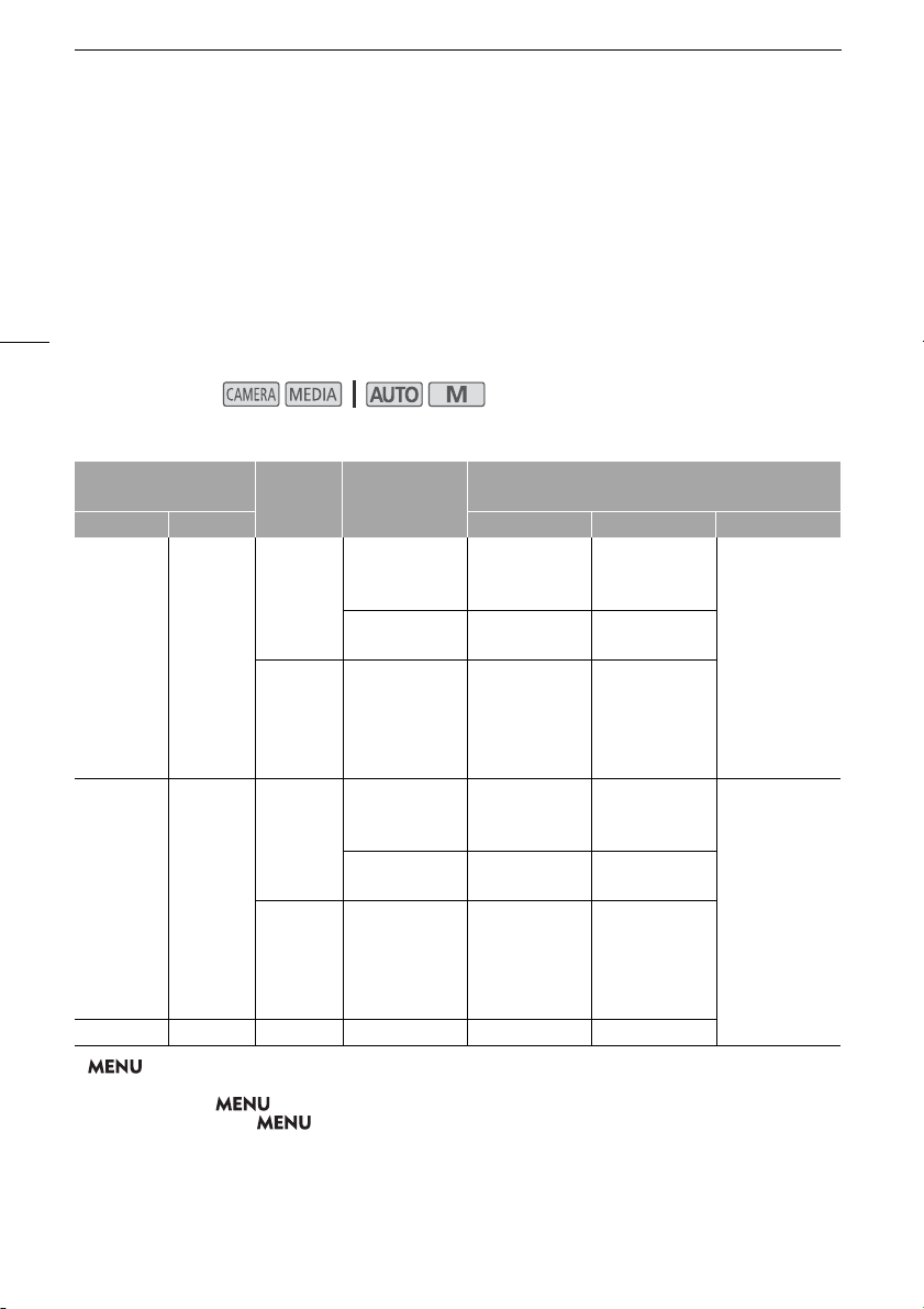
Video Output Configuration
External Connections
6
External Connections
Video Output Configuration
The video signal output from the SDI OUT terminal (s only) and HDMI™ OUT terminal depends
on the clip's video configuration and on various menu settings. The video signal output from the HDMI
OUT terminal can also change depending on the capabilities of the connected monitor.
94
s The camcorder cannot output signals to the SDI OUT terminal and HDMI OUT terminal
simultaneously.
Operating modes:
Video Output Configuration (Recording)
Recording video
configuration
Resolution Frame rate Resolution Frame rate Color sampling
3840x2160
1920x1080
1280x720 59.94P — — 1280x720 59.94P
1
setting.
2
For HDMI output: > [£ Display Setup] > [HDMI Max Resolution] setting.
s For SDI output: > [£ Display Setup] > [SDI Output] setting.
3
The frame rate is 59.97P during slow & fast motion recording.
4
s only.
5
HDMI output only. Only when the frame rate is set to 59.97P. Automatically selected depending on the
capabilities of the connected monitor.
29.97P
23.98P
59.94P
29.97P
23.98P
> [£ Display Setup] > [SDI/HDMI Scan Mode] (s) or [HDMI Scan Mode] (t)
Scan mode
setting
P
PsF — 1920x1080
P
PsF — 1920x1080
Maximum
resolution
1
2
setting
1920x1080 1920x1080
1280x720
(59.94P)
1920x1080
1280x720
(59.94P)
Video output configuration
Same as that for
video
configuration
1280x720 59.94P
SDI output4:
29.97PsF
(59.94i)
HDMI output:
59.94i
5
Same as that for
video
configuration
SDI output4:
29.97PsF
(59.94i)
HDMI output:
59.94i
1920x1080
720x480
1280x720 59.94P
3
3
YCbCr 4:2:2
8 bit
YCbCr 4:2:2
10 bit
Page 95
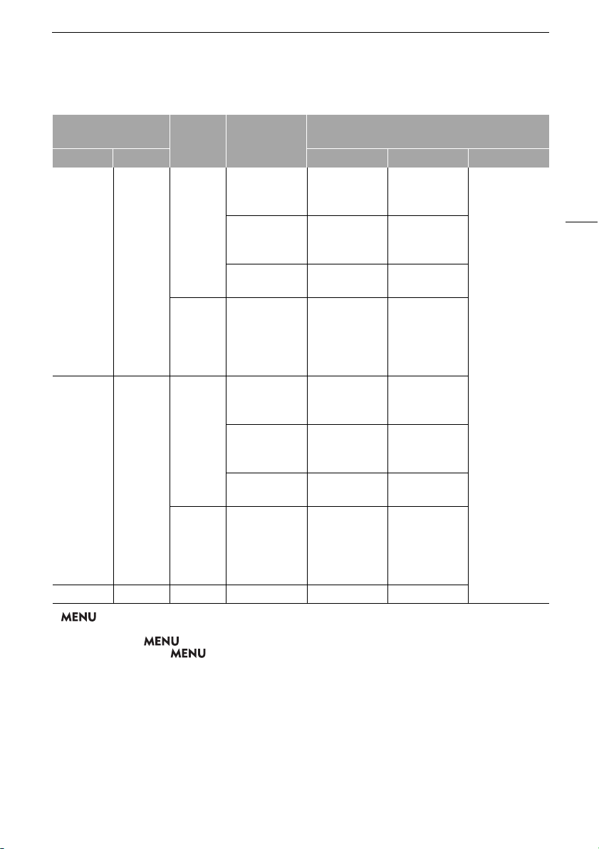
Video Output Configuration
Video Output Configuration (Playback)
Video configuration
of the clip
Resolution Frame rate Resolution Frame rate Color sampling
Scan mode
setting
P
3840x2160
29.97P
23.98P
Maximum
resolution
1
setting
2
3840x2160 3840x2160
1920x1080 1920x1080
1280x720
(59.94P)
Video output configuration
Same as that for
3
video
configuration
Same as that for
3
video
configuration
1280x720 59.94P
3
3
SDI output4:
29.97PsF
PsF — 1920x1080
(59.94i)
HDMI output:
3840x2160 1920x1080
Same as that for
3
59.94i
video
YCbCr 4:2:2
8 bit
configuration
Same as that for
3
configuration
video
1920x1080
59.94P
29.97P
23.98P
P
1920x1080 1920x1080
1280x720
(59.94P)
1280x720 59.94P
SDI output4:
29.97PsF
PsF — 1920x1080
(59.94i)
HDMI output:
59.94i
1280x720 59.94P — — 1280x720 59.94P
1
2
3
4
5
> [£ Display Setup] > [SDI/HDMI Scan Mode] (s) or [HDMI Scan Mode] (t)
setting.
For HDMI output: > [£ Display Setup] > [HDMI Max Resolution] setting.
s For SDI output: > [£ Display Setup] > [SDI Output] setting.
s Only HDMI output is available for this video configuration.
s only.
YCbCr 4:2:0 video recorded on the card is output as a YCbCr 4:2:2 signal.
95
5
Page 96
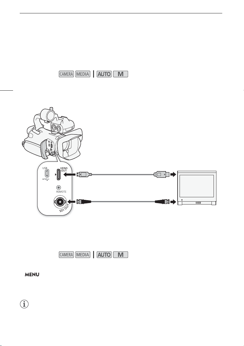
Connecting to an External Monitor
NOTES
HDMI IN
terminal
SDI IN
terminal
HDMI OUT
terminal
SDI OUT
terminal*
* s only
HTC-100 High Speed
HDMI Cable (optional)
BNC cable
(commercially available)
Connecting to an External Monitor
When you connect the camcorder to an external monitor for playback, use the terminal that matches
the one you with to use on the monitor (s only) or the HDMI OUT terminal. Then, select the video
signal output configuration. You can output also the onscreen displays (A 108).
Operating modes:
96
Connection Diagram
We recommend that you power the camcorder from a power outlet using the compact power adapter.
s
Selecting the Terminal Used For Output
Select in advance to output video and audio signals from the SDI OUT terminal or HDMI OUT terminal.
Operating modes:
1 Select [Output Terminal].
> [£ ! Display Setup] > [Output Terminal]
2 Activate the output terminal and then select [X].
• Select [ø SDI] (SDI OUT terminal) or [ù HDMI] (HDMI OUT terminal), depending on the
connection you wish to use.
• The camcorder cannot output signals to the SDI OUT terminal and HDMI OUT terminals
simultaneously.
Page 97
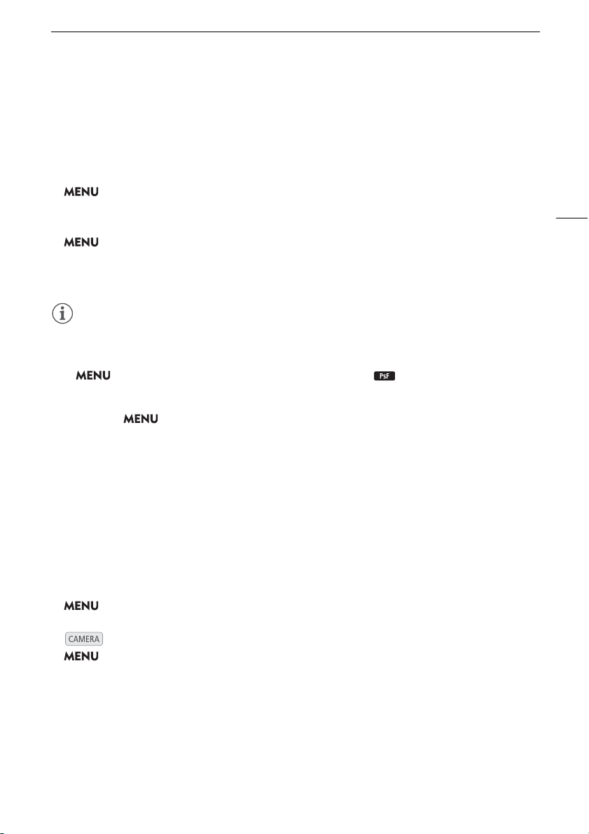
Connecting to an External Monitor
NOTES
s Using the SDI OUT Terminal
The digital signal that is output from the SDI OUT terminal includes the video signal, audio signal, time
code and recording command. You can output also the onscreen displays (A 108).
Make sure the SDI OUT terminal is set for output in advance (A 96).
1 Select [SDI Output].
> [£!Display Setup] > [SDI Output]
2 Select the desired maximum resolution and then select [L].
3 Select [3G-SDI Mapping].
> [£!Display Setup] > [3G-SDI Mapping]
4 Select the desired option and then select [L].
• You can select a video output signal compliant with Level A or Level B of the SMPTE ST 425-1
standard.
• The time code signal will not be output from the SDI OUT terminal when slow & fast motion
recording is activated.
• The frames value in the time code will run from 0 to 29 instead of 0 to 23 in the following cases.
- > [£ Display Setup] > [SDI/HDMI Scan Mode] is [ PsF (Forced 1080i)] and the
frame rate is 23.98P.
- When the output is 1280x720.
3
• You can set > [
camcorder’s START/STOP button to control also the recording operation of an external recorder
connected to the SDI OUT terminal.
Recording Setup] > [Rec Command] to [i On] to use the
97
Using the HDMI OUT Terminal
The digital signal that is output from the HDMI OUT terminal includes the video signal and audio signal.
You can output also the time code signal and some assistance displays (onscreen displays, markers,
etc.) in order to check them also on an external monitor. s Make sure the HDMI OUT terminal is
set for output in advance (A 96).
The audio output signal will be 2-channel linear PCM audio (16-bit, 48 kHz sampling).
1 Select [HDMI Max Resolution].
> [£!Display Setup] > [HDMI Max Resolution]
2 Select the desired maximum resolution and then select [L].
3 mode only: To output the time code signal, select [HDMI Time Code].
> [3" Recording Setup] > [HDMI Time Code]
4 Select [On] and then select [X].
Page 98
Connecting to an External Monitor
NOTES
• The HDMI OUT terminal on the camcorder is for output only. Do not connect it to an HDMI output
terminal on an external device, as this may damage the camcorder.
• Correct operation cannot be guaranteed when connecting the camcorder to DVI monitors.
• Video may not be output correctly depending on the monitor.
• If the connected monitor is not compatible with the signal output from the camcorder, then HDMI
98
output will stop.
• The time code signal will not be output from the HDMI OUT terminal in the following cases.
-In mode.
- When slow & fast motion recording is activated.
- When the output is 720x480 / 59.94P.
• The frames value in the time code will run from 0 to 29 instead of 0 to 23 in the following cases.
- > [
(t only) is [ PsF (Forced 1080i)] and the frame rate is 23.98P.
- When the output is 1280x720.
• You can set both > [3 Recording Setup] > [Rec Command] and [HDMI Time Code] to
[i On] to use the camcorder’s START/STOP button to control also the recording operation of an
external recorder connected to the HDMI OUT terminal. The camcorder’s time code signal will be
output as well.
£ Display Setup] > [SDI/HDMI Scan Mode] (s only) or [HDMI Scan Mode]
Page 99
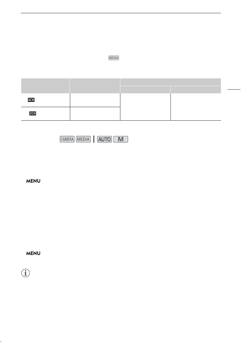
Audio Output
NOTES
Audio Output
The camcorder can output audio from the SDI OUT terminal (s only), HDMI OUT terminal, ×
(headphone) terminal or speaker (monaural; mode only). When recording or playing back clips
recorded with 4-channel audio, you can select the 2-channel output.
Audio output configuration
Audio configuration of the
MP4 audio format
[ LPCM 16bit 4CH]
[ AAC 16bit 2CH]
1
[3 Recording Setup] > [¸ Audio Format] setting.
Operating modes:
1
recorded clips
4-channel linear PCM,
16 bit
2-channel AAC,
bit rate: 256 kbps
s SDI OUT terminal HDMI OUT terminal
4-channel linear PCM,
Selecting the Audio Channels for Headphone or Speaker Output
You can select the 2-channel output from the × (headphone) terminal or speaker.
1 Select [Monitor Channels].
> [¡#Audio Setup] > [Monitor Channels]
2 Select the desired option and then select [
• The options show combinations of audio channels output from the left and right (L/R),
respectively. Options with a “+” sign ([CH1+2], for example) indicate a mix of two audio channels
on the same side.
X].
Audio output configuration
24 bit
2-channel linear PCM,
16 bit
99
Selecting the Audio Channels for HDMI Output
The audio signal output from the HDMI OUT terminal will be 2-channel linear PCM audio (16-bit,
48 kHz sampling).
1 Select [HDMI Channels].
> [¡#Audio Setup] > [HDMI Channels]
2 Select the desired option and then select [
• If you set an assignable button to [Monitor Channels] (A 85), you can press the button to toggle
between the audio channel output options.
X].
Page 100

Working with Clips on a Computer
Saving Clips
7
Saving Clips
Working with Clips on a Computer
Make sure to save clips recorded with this camcorder to a computer. To do so, you will need a card
reader connected to a computer or a computer with an SD card slot. For details on transferring files
from the SD card, refer to the computer’s instruction manual or OS’s help modules.
100
Under certain circumstances, clips may be split and recorded as separate files. Using MP4 Join Tool
you can join the split files of and save them as a single seamless clip.
Transferring Files to the Computer
1 Insert an SD card with the desired clips into the SD card slot of the computer or card
reader connected to the computer.
2 Follow the OS’s onscreen instructions.
3 Copy the clips on the SD card to the computer.
• Recordings on the SD card are located in folders named “XXX_mmdd” under the “DCIM” folder,
where XXX is the folder number (100 to 999) and mmdd stands for the recording date (A 107).
Joining Clips Split by the Camcorder
Use MP4 Join Tool to join clips split by the camcorder in the following cases.
• When the camcorder switches to the other SD card while recording video due to the relay recording
function (A 32).
• The video (stream) file in the clip will be split approximately every 4 GB.
MP4 Join Tool is available as a free download (for Windows or macOS) from your local Canon website.
Check the download page for the system requirements and latest information.
You will find detailed instructions about installing and uninstalling the software in the “Read This First”
file (Install-MP4 Join Tool.pdf) included in the compressed file you download. For details about using
the software, refer to the instruction manual (PDF file) that is installed with the software.
 Loading...