

Page 1
CANON INC. 30-2, Shimomaruko 3-chome, Ohta-ku, Tokyo 146-8501, Japan
U.S.A. CANON U.S.A.,INC. NEW JERSEY OFFICE
100 Jamesburg Road, Jamesburg, NJ 08831 USA
CANON U.S.A.,INC. CHICAGO OFFICE
100 Park Blvd., Itasca, IL 60143 USA
CANON U.S.A.,INC. LOS ANGELES OFFICE
15955 Alton Parkway, Irvine, CA 92618 USA
CANON U.S.A.,INC. HONOLULU OFFICE
210 Ward Avenue, Suite 200 Honolulu, HI 96814 USA
● If you have any questions, call the Canon U.S.A. Information
Center toll-free at 1-800-828-4040(U.S.A.only)
CANADA CANON CANADA INC.NATIONAL HEADQUARTERS
6390 Dixie Road, Mississauga, Ontario L5T 1P7
CANON CANADA INC. CALGARY
2828, 16th Street, N.E, Calgary, Alberta T2E 7K7
CANON CANADA INC. MONTRÉAL
5990 Côte-de-Liesse, Montréal, Québec H4T 1V7
● If you have any questions, call the CANON CANADA Customer Information
Centre toll-free at 1-800-OK-CANON (652-2666) (Canada only)
MEXICO CANON MEXICANA, S. DE R.L.DE C.V.
Periferco Sur No. 4124, Col. Ex-Rancho de Anzaldo, C.P. 01900
México, D.F., México
CENTROY
SURAMERICA CANON LATIN AMERICA, INC.
6505 Blue Lagoon Drive, Suite 325, Miami, FL 33126, USA
ASIA CANON SINGAPORE PTE. LTD.
79 Anson Road, #09-01/06, Singapore 079906 Republic of Singapore
CANON HONGKONG CO., LTD.
9/F., The Hong Kong Club Building, 3A, Chater Road, Central, Hong Kong
OCEANIA CANON AUSTRALIA PTY.LTD.
1 Thomas Holt Drive, North Ryde, Sydney, N.S.W. 2113, Australia
EUROPE CANON EUROPA N.V.
P.O.Box 2262, 1180 EG Amstelveen, The Netherlands
CANON EUROPE LTD.
6 Roundwood Avenue, Stockley Park, Uxbridge Middlesex, UB11 1JA, United Kingdom
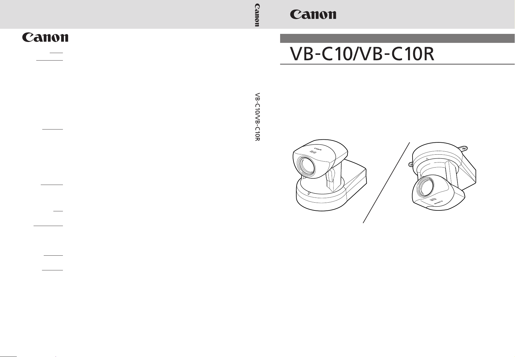
NETWORK CAMERA
NETWORK CAMERA
User’s Manual
User’s Manual
VB-C10 VB-C10R
PUB.YT1-1000-000 xxxxxxxx © CANON INC.2002 PRINTED IN JAPAN
Please read this instruction manual carefully before operation.
Be sure to read the “a Safe Use of Equipment” section before using
this equipment. Store this manual in a readily accessible location for
future reference.
´
ENGLISH
Page 2
Introduction
Thank you for purchasing the Canon Network Camera VB-C10/VB-C10R (referred to hereafter as
the VB-C10/VB-C10R).
This manual describes how to set up and use the VB-C10/VB-C10R. Read this manual carefully
before using the VB-C10/VB-C10R to ensure effective operation. In particular make sure that you
read the "a Safe Use of Equipment" in this manual, as well as the supplied CD-ROM Readme file.
Exclusion of Liability
If the Product is connected to a recording device (for example a VCR), Canon Inc. accepts
no responsibility whatsoever for any financial losses that may be incurred as a result of
the loss of recorded information or images, regardless of the internal or external cause of
the loss.
Copyright Information
Video or still pictures recorded using your VB-C10/VB-C10R cannot be used in ways that infringe
copyright laws or without the consent of the owner, unless intended for personal use only.
Notes
1. The unauthorized transfer of all or any part of the contents of this Manual is forbidden.
2. The contents of this Manual are subject to change without notice.
3. Every effort has been made to ensure that this Manual is flawless. However, if you find any
oversights, please let us know.
4. Item 3. notwithstanding, Canon accepts no responsibility for any effects resulting from the use
of this Manual.
Trademark Notices
● Canon and Canon logo are registered trademarks of Canon Inc.
● Microsoft and Windows are registered trademarks of Microsoft Corporation in the United States
and other countries.
● Windows is legally recognized as Microsoft Windows Operating System.
● Other brand or product names in this manual may be trademarks or registered trademarks of
their respective companies.
● This product uses Linux kernel, gcc-libs, readline, init, sftpd, net-tools, mactool, telnetd, syslogd
and boa under license of GNU General Public License (GPL); glibc and termcap under license
of GNU Lesser General Public License (LGPL); and ash, sh and ping under license of modified
BSD License.
Documents of Linux kernel COPYING, GPL, LGPL, and modified BSD License are stored as
the files of COPYING.txt, GPL.txt, LGPL.txt and mBSD.txt respectively within LICENSE folder
of accompanied CD rom with the package.
If you (customer) need program source codes under the terms and conditions of GPL and/or
LGPL, please access
http://www.canon.com/webview/webview-tech/
ii
Page 3
Request concerning disclosure of live videos
With respect to the disclosure of live videos, we request that sufficient consideration be
given to matters of privacy and rights not to be photographed. Canon considers the following
points concerning such matters when it operates camera sites for which it has been
responsible to install and operate:
● We take measures such as adding limitations on zoom magnifications so that people
cannot make special specifications.
● When videos are taken of specific buildings, interiors and the like, we install the camera
only after receiving approval from the administrator.
Please note that the operator of the camera site and not Canon has full responsibility
regarding the disclosure of live videos.
© Copyright 2002 CANON INC.
ALL RIGHTS RESERVED
Introduction
Styles
iii
Page 4

Contents
Introduction ............................................................................ ii
a
Safe Use of Equipment.................................................... vii
Maintenance .............................................................................................................. xii
Chapter 1 Before Using the VB-C10/VB-C10R
Features of the VB-C10/VB-C10R ................................................................ 1-2
System Configuration .................................................................................. 1-4
Hardware and Software Requirements ....................................................... 1-6
Webview Livescope Viewer Software ...................................................................... 1-6
VB Administration Tools ........................................................................................... 1-6
VBCollector .............................................................................................................. 1-7
Webview Livescope MV version 2.0/LE ................................................................... 1-7
Package Contents ......................................................................................... 1-8
System Components and Their Operation ................................................. 1-9
Chapter 2 Installation
Before Using the VB-C10/VB-C10R ............................................................. 2-2
Installing the VB-C10/VB-C10R ............................................................................... 2-2
Connecting the Components ................................................................................... 2-4
Turning the Power ON and OFF .............................................................................. 2-4
Sample Network Configurations ................................................................. 2-5
Sample LAN Environment Configuration ................................................................. 2-5
Sample Configuration in an ISP Environment .......................................................... 2-5
Chapter 3 Setup Procedures
Preparations for Initial Setup ....................................................................... 3-2
Initial Setup ................................................................................................... 3-3
Checking Operation ...................................................................................... 3-6
Detail Settings ............................................................................................... 3-7
Accessing the Settings Title Page............................................................................ 3-7
Settings Title Page ................................................................................................... 3-8
System/Network Settings Page ............................................................................... 3-9
Date/Time Settings Page ....................................................................................... 3-10
Camera Settings Page ............................................................................................ 3-11
Preset Settings Page ............................................................................................. 3-15
Picture Recording and External Device I/O Settings Page .................................... 3-16
Access Control Settings Page ............................................................................... 3-19
WebView Livescope Setting Settings Page ........................................................... 3-20
Miscellaneous Settings Page ................................................................................. 3-21
Administration Tools Settings Page ....................................................................... 3-22
iv
Page 5

Chapter 4 VB Administration Tools
Overview of VB Administration Tools ......................................................... 4-2
VBAdmin Startup Panel ........................................................................................... 4-2
Panorama Creation Tool .......................................................................................... 4-2
View Restriction Tool ................................................................................................ 4-3
Preset Setting Tool ................................................................................................... 4-3
Log Viewer ............................................................................................................... 4-3
Admin Viewer ........................................................................................................... 4-3
Installing VB Administration Tools .............................................................. 4-4
Starting Up VB Administration Tools .......................................................... 4-5
Panorama Creation Tool ............................................................................... 4-7
About the Panorama Creation Tool Display Screen ................................................. 4-8
Capturing Panorama Pictures .................................................................................. 4-9
Updating/Deleting Panorama Pictures ................................................................... 4-10
Reconnecting .......................................................................................................... 4-11
Opening/Saving Pictures ........................................................................................ 4-11
Displaying Connection Information ......................................................................... 4-11
View Restriction Tool .................................................................................. 4-12
The View Restriction Tool Display Screen ............................................................. 4-13
Setting View Restrictions ....................................................................................... 4-15
Preset Setting Tool...................................................................................... 4-17
Preset Setting Tool Display Screen ........................................................................ 4-18
Setting Presets ....................................................................................................... 4-20
Log Viewer ................................................................................................... 4-22
Viewing Logs .......................................................................................................... 4-22
Admin Viewer .............................................................................................. 4-24
Starting Up Admin Viewer ...................................................................................... 4-24
Operating External Device ..................................................................................... 4-25
Enabling/Disabling View Restrictions ..................................................................... 4-26
Contents
Styles
Chapter 5 Creating Web Pages
Web Pages for Video Distribution ............................................................... 5-2
Features of the Java Viewers .................................................................................. 5-3
Features of the Helper Viewer ................................................................................. 5-5
Viewing Sample Pages ................................................................................. 5-6
Using the Java Viewer to Distribute Videos ................................................ 5-7
Using the Java Viewer to Create a Web Page ......................................................... 5-7
Saving Web Page Data ............................................................................................ 5-8
Example of Using the Java Viewer to Create a Web Page ...................................... 5-9
Java Viewer Parameters ........................................................................................ 5-17
v
Page 6

Contents
Using the Helper Viewer to Distribute Videos .......................................... 5-21
Example of a Web page Using the Helper Viewer ................................................. 5-23
Distributing Videos Using a Browser Only ............................................... 5-24
Example of Video Distribution Using One Fixed Global Address .......... 5-26
Chapter 6 Using the Picture Recording Function
Using the Still Picture Recording Function Linked to an External Device ...
Sample Application Combining a Door-opening Sensor .......................................... 6-2
Using the Still Picture Recording Function with a Predetermined Schedule ....
Sample Application Using Sequential Mode ............................................................ 6-4
Viewing Recorded Pictures ......................................................................... 6-6
Installing VBCollector ............................................................................................... 6-7
Starting Up VBCollector ........................................................................................... 6-8
Registering a Server ................................................................................................ 6-8
Registering Tasks ................................................................................................... 6-10
Executing and Canceling Tasks ............................................................................. 6-12
Details Displayed on the Task View ....................................................................... 6-13
Starting/Stopping the Service ................................................................................ 6-14
Viewing Recorded Images ..................................................................................... 6-14
Viewing Logs .......................................................................................................... 6-16
Setting Download Capacity .................................................................................... 6-18
6-2
6-4
Chapter 7 Troubleshooting
Troubleshooting ............................................................................................ 7-2
Log Messages ............................................................................................... 7-4
Chapter 8 Appendix
Specifications ............................................................................................... 8-2
External Device I/O Terminals .................................................................................. 8-3
Restoring the Factory Default Settings ...................................................... 8-4
Restoring the Factory Default Settings from the Administration Tools Page via a Web Browser ....
If the IP Address and Password are Unknown......................................................... 8-5
Factory Default Setting ................................................................................ 8-6
Index .............................................................................................................. 8-8
vi
8-4
Page 7
a Safe Use of Equipment
An exclamation point, within a triangle, is intended to alert the user to the presence of
a
important operating and maintenance (servicing) instructions in the literature
accompanying the equipment.
a Important Warnings
a CAUTION:
TO REDUCE THE RISK OF ELECTRIC SHOCK, DO NOT REMOVE COVER (OR
BACK). NO USER-SERVICEABLE PARTS INSIDE. REFER SERVICING TO
QUALIFIED SERVICE PERSONNEL.
The serial number of this equipment may be found on the bottom of the VB-C10/
VB-C10R. No others have the same serial number as yours.
You should record the number and other vital information here and retain this book
as a permanent record of your purchase to aid identification in case of theft.
Date of Purchase
Dealer Purchased from
Dealer Address
Dealer Phone No.
Model No. VB-C10 or VB-C10R
Serial No.
a Important Operational Instructions
a WARNING:
TO REDUCE THE RISK OF ELECTRIC SHOCK, DO NOT EXPOSE THIS
EQUIPMENT TO RAIN OR MOISTURE.
a CAUTION:
TO REDUCE THE RISK OF ELECTRIC SHOCK AND TO REDUCE ANNOYING
INTERFERENCE, USE THE RECOMMENDED ACCESSORIES ONLY.
FDA regulation
This Network Camera has not been evaluated by the Food and Drug Administration
(FDA) for use as a medical device. When incorporated into a system with medical
applications, FDA regulations may apply. Therefore, please consult your legal
advisor to determine whether FDA regulations apply.
Styles
vii
Page 8
a
Safe Use of Equipment
This device complies with Part 15 of the FCC Rules. Operation is subject to the
following two conditions: (1) This device may not cause harmful interference, and
(2) this device must accept any interference received, including interference that
may cause undesired operation.
Note: This equipment has been tested and found to comply with the limits for a
Class B digital device, pursuant to Part 15 of the FCC Rules. These limits are
designed to provide reasonable protection against harmful interference in a
residential installation. This equipment generates, uses and can radiate radio
frequency energy and, if not installed and used in accordance with the instructions,
may cause harmful interference to radio communications.
However, there is no guarantee that interference will not occur in a particular
installation. If this equipment does cause harmful interference to radio or television
reception, which can be determined by turning the equipment off and on, the user
is encouraged to try to correct the interference by one or more of the following
measures:
- Reorient or relocate the receiving antenna.
- Increase the separation between the equipment and receiver.
- Connect the equipment into an outlet on a circuit different from that to which the
receiver is connected.
- Consult the dealer or an experienced radio/TV technician for help.
Use of shielded cable is required to comply with class B limits in Subpart B of Part
15 of FCC Rules.
Do not make any changes or modifications to the equipment unless otherwise
specified in the manual. If such changes or modifications should be made, you
could be required to stop operation of the equipment.
Canon U.S.A. Inc.
One Canon Plaza, Lake Success, NY 11042, U.S.A.
Tel No. (516) 328-5600
FCC NOTICE
Network Camera VB-C10/VB-C10R
viii
IC NOTICE
This product does not exceed the Class B limits for radio noise emissions from
digital apparatus as set out in the Interference-causing equipment standard entitled
‘Digital Apparatus’, ICES-003 of the Industry Canada.
NOTIFICATION IC
Cet appareil numériquw respecte les limites de bruits radioélectriques applicables
aux appareils numériques de Classe B prescrites dans la norma sur le matériel
brouilleur: “Appareils Numériques”, NMB-003 édictées par I’lndustrie Canada.
Dieses Produkt ist zum Gebrauch im Wohnbereich, Geschäfts- und Gewerbebereich
sowie in Kleinbetrieben vorgesehen.
Page 9

a IMPORTANT SAFETY INSTRUCTIONS
a
Safe Use of Equipment
In these safety instructions, the word
“equipment” refers to the Canon Network
Camera VB-C10/VB-C10R and all its
accessories.
1. Read Instructions - All the safety and
operating instructions should be read before
the equipment is operated.
2. Retain Instructions - The safety and operating
instruction should be retained for future
reference.
3. Heed Warnings - All warnings on the
equipment and in the operating instructions
should be adhered to.
4. Follow Instructions - All operating and
maintenance instructions should be followed.
5. Cleaning - Unplug this equipment from the
wall outlet before cleaning.
Wipe the equipment with a clean soft cloth. If
necessary, put a cloth in diluted neutral
detergent and wring it well before wiping the
equipment with it. Finally, clean the
equipment with a clean dry cloth. Do not use
benzene, thinner or other volatile liquids or
pesticides as they may damage the product’s
finish. When using chemically-treated
cleaning cloths, observe those precautions
accordingly.
6. Accessories - Do not use accessories not
recommended in this manual as they may
be hazardous. Always use specified
connection cables. Connect devices correctly.
7. Water and Moisture - Hazard of electric shock
- Do not use the equipment near water or in
rainy/moist situations. Do not put a heater
near this equipment.
8. Placing or Moving - Do not place on an
unstable cart, stand, tripod, bracket or table.
The equipment may fall, causing serious
injury to a child or adult, and
serious damage to the
equipment. An equipment and
cart combination should be
moved with care.
Quick stops, excessive force, and uneven
surfaces may cause the equipment and cart
combination to overturn.
9. Power Sources - The PA-V16 AC adapter
should be operated only from the type of power
source indicated on the marking label. If you
are not sure of the type of power supply to your
home, consult your equipment dealer or local
power company.
10. Polarization - The PA-V16 AC adapter is
equipped with a polarized 2-prong plug (a plug
having one blade wider than the other).
The 2-prong polarized plug will fit into the
power outlet only one way. This is a safety
feature. If you are unable to insert the plug
fully into the outlet, try reversing the plug. If
the plug still fails to fit, contact your electrician
to replace your obsolete outlet. Do not defeat
the safety purpose of the polarized plug.
11. Power Cord Protection - Power cords should
be routed so that they are not likely to be
walked on or pinched by items placed upon
or against them. Pay particular attention to
plugs and the point from which the cords exit
the equipment.
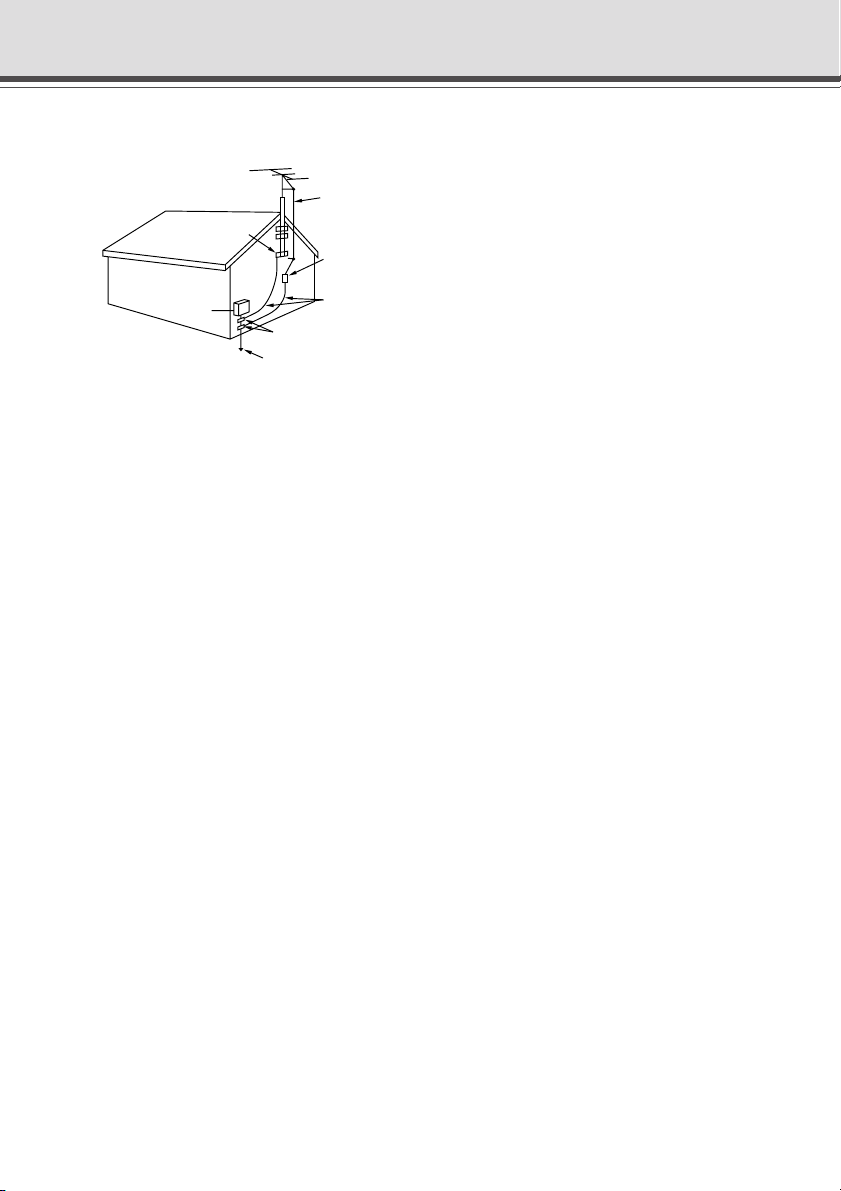
12. Outdoor Antenna Grounding - If an outside
antenna is connected to the equipment, be
sure the antenna is grounded so as to provide
some protection against voltage surges and
built-up static charges. Section 810 of the
National Electrical Code, ANSI/NFPA No.701984, provides information with respect to
proper grounding of the mast and supporting
structure, grounding of the lead-in wire to an
antenna discharge unit, size of grounding
conductors, location of antenna antenna
discharge unit, connection to grounding
electrodes, and requirements for the
grounding electrode. See figure 1.
Styles
ix
Page 10
a
Safe Use of Equipment
fig-1
EXAMPLE OF ANTENNA GROUNDING AS
PER NATIONAL ELECTRICAL CODE
ANTENNA
LEAD IN WIRE
GROUNDING
CLAMP
ELECTRIC
SERVICE
EQUIPMENT
NEC — NATIONAL ELECTRIC CODE
ANTENNA
DISCHARGE
UNIT (NEC
SECTION 810-20)
GROUNDING
CONDUCTORS
(NEC SECTION
810-21)
GROUNDING CLAMPS
POWER SERVICE
GROUNDING ELECTRODE
SYSTEM
(NEC ART 250. PART H)
13. Lightning - For added protection of this
equipment during a lightning storm, or when
it is left unattended and unused for long
periods of time, disconnect it from the wall
outlet and disconnect the antenna. This will
prevent damage to the equipment due to
lightning and power-line surges.
14. Power Lines - An outside antenna system
should not be located in the vicinity of
overhead power lines or other electric light
or power circuits, or where it can fall into such
power lines or circuits. When installing an
outside antenna system, extreme care should
be taken to keep from touching such power
lines or circuits as contact with them might
be fatal.
15. Overloading - Do not overload wall outlets and
extension cords as this can result in a risk of
fire or electric shock.
16. Object and Liquid Entry - Never push objects
of any kind into this equipment through
openings as they may touch dangerous
voltage points or short out parts that could
result in a fire or electric shock. Be careful
not to spill liquid of any kind onto the
equipment.
17. Servicing - Do not attempt to service this
equipment yourself as opening or removing
covers may expose you to dangerous voltage
or other hazards. Refer all servicing to
qualified personnel.
18. Damage Requiring Service - Disconnect this
equipment from the wall outlet and all power
sources including batteries, and refer
servicing to qualified service personnel under
the following conditions.
a. When the power-supply cord or plug is
damaged.
b. If any liquid has been spilled onto, or
objects have fallen into, the equipment.
c. If the equipment has been exposed to rain
or water.
d. If the equipment does not operate normally
even if you follow the operating instructions.
Adjust only those controls that are covered
by the operation instructions. Improper
adjustment of other controls may result in
damage and will often require extensive
work by a qualified technician to restore
the equipment to its normal operation.
e. If the equipment has been dropped or the
cabinet has been damaged.
f. When the equipment exhibits a distinct
change in performance. This indicates a
need for service.
19. Replacement Parts - When replacement parts
are required, be sure the service technician
has used replacement parts that are specified
by Canon or that have the same
characteristics as the original part.
Unauthorized substitutions may result in fire,
electric shock or other hazards.
20. Safety Check - Upon completion of any
service or repairs to this equipment, ask the
service technician to perform safety checks
to determine that the equipment is in safe
operating order.
21. Do not install the equipment in the following
locations as this can cause a fire or electric
shock:
- Hot locations
- Close to a fire
- Very humid or dusty locations
x
Page 11

- Locations exposed to direct sunlight
- Locations exposed to salt spray
- Close to flammable solvents (alcohol,
thinners, etc.)
22. When any of the following occurs,
immediately switch OFF the equipment,
unplug it from the main power supply and
contact your nearest Canon supplier. Do not
continue to use the equipment as this can
cause a fire or electric shock.
- The equipment emits any smoke, heat,
abnormal noise, or unusual odor.
- A metal object falls into the equipment.
- The equipment is damaged in some way.
23. Please observe the following when using the
equipment. Failure to do so can result in a
fire or electric shock.
- Do not use flammable sprays near the
equipment.
- Do not subject the equipment to strong
impacts.
a
Safe Use of Equipment
Styles
xi
Page 12
a
Safe Use of Equipment
Maintenance
Cleaning the Equipment
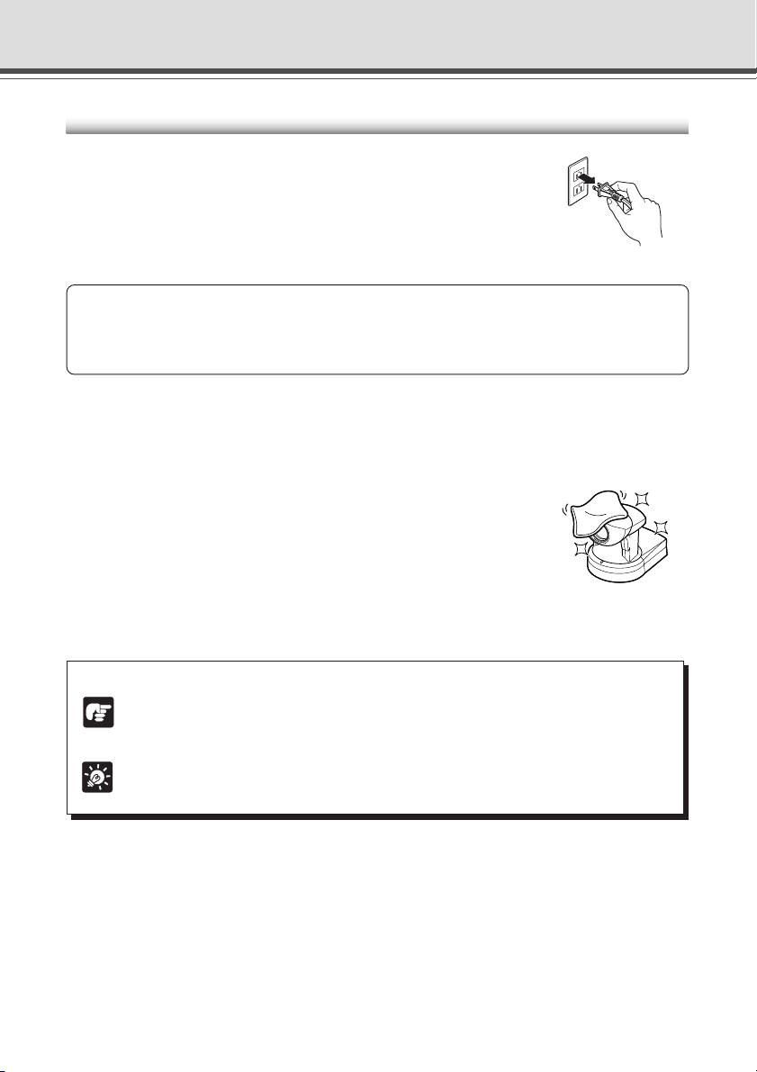
1. Unplug the AC adapter from the wall outlet.
2. Carefully wipe the equipment with a soft cloth that has
been moistened with water or a mild detergent.
a WARNING:
Do not use flammable solvents such as alcohol, benzene or thinners.
The use of such substances can cause a fire or electric shock.
3. Wipe with a dry cloth.
4. When you have finished, plug the AC adapter back in to the wall outlet.
Cleaning the Lens
Use a commercially available lens cleaner to remove any soiling from the
lens.
● The auto-focus may not function correctly if the surface of the lens is
dirty.
● Scratches on the surface of the lens will cause image defects.
Icons Used in This Instruction Manual
Indicates important information that must be observed or actions that are prohibited
during an operation. These notes must be read to prevent possible faults or damage
Note
to the equipment.
Indicates supplementary information or a reference to an operation. Users are advised
to read these memos.
Tip
xii
Page 13

Chapter
Before Using the VB-C10/VB-C10R
This chapter contains information that you should read
before using the VB-C10/VB-C10R. It also describes the
features of the VB-C10/VB-C10R, the system configuration,
the hardware and software requirements, and the name and
functions of the system components.
Page 14

Features of the VB-C10/VB-C10R
The VB-C10/VB-C10R is a system that distributes live videos via the Internet or an Intranet. It can
be used in a wide range of applications, such as distributing live videos from a Web site or
monitoring. The system is configured of the VB-C10/VB-C10R and viewer software. Please use
the supplied viewer software for viewing videos distributed by the VB-C10/VB-C10R and controlling
cameras.
Broadband Video Distribution Function
The VB-C10/VB-C10R is capable of capturing videos at up to 30 fps. Motion-JPEG is used to
compress video images. For networking, auto-negotiation between Ethernet 100Base-TX/
10Base-T is provided and a leased line or ADSL can also be used through a router. Since
video quality (in 5 levels) and the frame rate (from 0.1 to 30 fps) can be freely set, videos can
be distributed under conditions that best suit the network bandwidth.
Concurrent video is distributed up to 20 clients
Up to 20 clients can view video at the same time from a single VB-C10/VB-C10R.
Camera and video distribution server functions housed in a single unit
The camera capable of full pan, tilt, and zoom functions and its server functions for distributing
videos through a network are compactly housed in a single unit. By simply connecting a LAN
cable and a power supply, the unit can distribute live videos from any location* where it is
installed.
* The unit cannot be installed in locations subject to direct sunlight, high temperatures, high humidity, or
other adverse conditions (→ P.ix).
High-performance 16x zoom and wide angle photographic range
The camera section is equipped with a 16x zoom lens. Furthermore, since the VB-C10 provides
a pan angle of 200 degrees (100 degrees each to the left and right) and a tilt angle of 120
degrees (90 degrees up and 30 degrees down), and the VB-C10R provides a pan angle of 340
degrees (170 degrees each to the left and right) and a tilt angle of 100 degrees (10 degrees up
and 90 degrees down), the VB-C10/VB-C10R are capable of recording wide areas.
Can be mounted on ceilings, etc. (VB-C10R)
The VB-C10R includes mounting plate, enabling it to be mounted in a variety of locations
including ceilings. The shape of the camera head has been designed so that pan and tilt
operations are still possible when mounted upside down.
Remote camera control from the viewer
The VB-C10/VB-C10R come with two types of viewer software: the Helper Viewer and the
Java Viewer. The viewers give you full remote control of the camera’s angle (pan and tilt) and
zoom magnification, allowing you to view videos with plenty of ambiance.
1-2
Page 15

Features of the VB-C10/VB-C10R
Panorama picture creation functions and settings
The entire photographic range of the camera can be created and saved as a panorama picture.
The saved panorama pictures can then be easily used to visually set view restrictions and
presets.
Camera Position Preset function
If often-used camera angles (camera head aim and zoom position) and related items are saved
in advance as presets, the camera can be controlled from the viewer by simply selecting a
desired preset. Up to 8 presets can be stored.
View Restriction function
You can set restrictions on camera angle specifications and zoom magnifications to prevent
viewers from seeing certain camera angles. For example, if the VB-C10/VB-C10R is being
used to operate a fixed point camera connected to the Internet, it is possible to distribute
videos while protecting privacy (→ P.iii, “Request concerning disclosure of live videos”).
Built-in Web server and FTP server
The VB-C10/VB-C10R is equipped with built-in Web server functions that enable both Web
pages and videos to be distributed through the Web by a single unit. Since it also has a built-in
FTP server, Web page data file transfers (FTP) can be performed from remote locations.
Before Using the VB-C10/VB-C10R
Simple set up and management
By accessing a Settings page provided on the Web, you can use the Web browser on your PC
to set up and manage the VB-C10/VB-C10R from a remote location without ever visiting the
place where the VB-C10/VB-C10R is actually installed.
More powerful security functions
The destinations for video distributions can be restricted based on passwords. Up to 20 clients
can be registered.
Recording videos via preset schedules or links with external devices
Still pictures can be recorded based on schedules set in advance or on ON/OFF events from
an external device. If VBCollector is used, still pictures recorded by the VB-C10/VB-C10R can
be automatically collected by a PC and viewed there.
1-3
Page 16
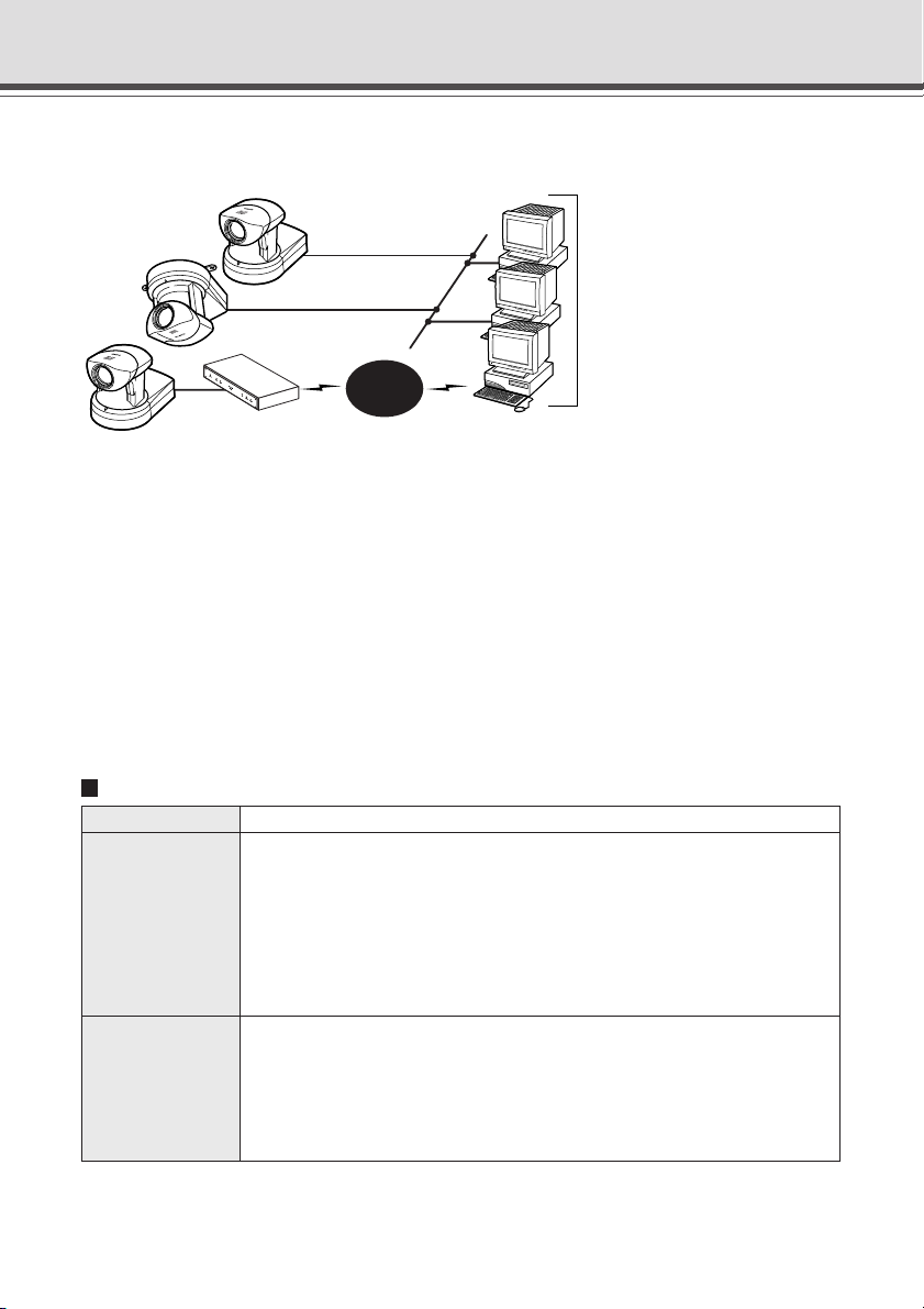
System Configuration
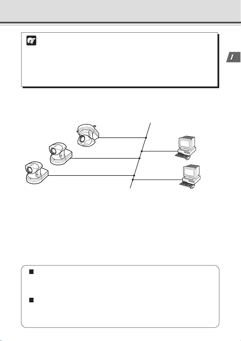
Example of Basic System Configuration - Viewing Videos Using a Viewer
VB-C10
Ethernet
Internet
(10/100Mbps)
WebView Livescope Viewer Software
(Java Viewer or Helper Viewer)
Recommended browser
● Netscape Navigator/
Communicator4.78 or later
● Internet Explorer 4.01 or later
VB-C10R
VB-C10
Router
This system configuration consists of the VB-C10/VB-C10R with WebView Livescope Viewer
Software (→ P.1-6). The WebView Livescope Viewer Software consists of the Helper Viewer
and the Java Viewer.
Helper Viewer must be installed in advance from the supplied CD-ROM, while Java Viewer is not
installed in advance but automatically downloaded from the VB-C10/VB-C10R. Since Java Viewer
is downloaded each time you want to view videos, it is useful when viewing videos for the first
time. Helper Viewer, however, is more convenient when you want to view videos frequently.
If you want to distribute live videos of places such as popular tourist destinations from Web pages,
it is best for your Web page visitors to use the Java Viewer that does not need to be installed in
advance.
Viewer Software Functions
Viewer Software Functions
• Videos from the VB-C10/VB-C10R can be displayed by a Web browser that can
run Java applet.
• Because the Java Viewer is automatically downloaded and does not need to be pre-
Java Viewer
Helper Viewer
installed, unlike the Helper Viewer, it is compatible with any platform that supports
Java-capable environments.
• Because it uses the HTTP protocol, the Java Viewer penetrates firewalls.
However, it may not run stably on some platforms or browser types.
Also, because the Viewer is downloaded when the Web page loads, start-up times and
execution speeds are slower than the Helper Viewer.
•A helper application for viewing videos from the VB-C10/VB-C10R that is launched
from a Web browser.
• The Helper Viewer must be pre-installed.
• Install Helper Viewer from the supplied CD-ROM.
• Compared with the Java Viewer, start-up is faster because the Viewer does not need
to be downloaded. This Viewer is recommended for users who use the viewer frequently.
• Because it supports the HTTP protocol, the Helper Viewer penetrates firewalls unscathed.
1-4
Page 17
System Configuration
● Install the Helper Viewer from the “MonSetup.exe” file on the supplied CD-ROM.
● The manual for the WebView Livescope software is provided on the supplied
Note
CD-ROM (Mon-E.pdf).
● To connect the VB-C10/VB-C10R to the Internet, you require a leased line
connection to an Internet service provider or a LAN-type dialup IP connection. If
you are using a LAN-type dialup connection, check that the connection supports
bidirectional calling.
Before Using the VB-C10/VB-C10R
Example of System Configuration with WebView Livescope MV
WebView Livescope MV
Ehernet
(10/100Mbps)
VB-C10R
VB-C10
VB-C10
Windows98SE/Me/NT4.0/2000/XP
(Internet Explorer 5 or later required)
- Optional
The WebView Livescope MV software (→ P.1-7) is convenient if there are several VB-C10/VB-
C10R installed on a LAN and you wish to concentrate on monitoring videos from them.
The WebView Livescope MV software consists of MV Manager and MV Station. MV Manager
lets you uniformly manage VB-C10/VB-C10R operating status. It also lets you select and create
a monitoring screen best suited to the number of VB-C10/VB-C10Rs on the LAN from among a
rich variety of examples. MV Station lets you use the monitoring screen created in MV Manager
to view videos from multiple points where VB-C10/VB-C10R units are installed while also remote
controlling cameras and external devices.
Optional Products
• Webview Livescope MV version 2.0
• Webview Livescope MV version 2.0 LE
Products sold separately
• Wide-angle Converter WL-37 (for VB-C10)
• Sensor
• Relay
1-5
Page 18
Hardware and Software Requirements
Webview Livescope Viewer Software (→ P.1-4)
The viewer software that are supplied with the VB-C10/VB-C10R. They lets you view the
VB-C10/VB-C10R’s videos and control the camera.
Java Viewer version 3.20
PC IBM PC/AT Compatible
Operating System Windows 98SE/Me or Windows NT 4.0 (IE4.0 or later required)/Windows 2000/
Web Browser Netscape Navigator/Communicator 4.78 or later (excluding 6.01 and 6.1),or Microsoft
* This viewer is installed on the VB-C10/VB-C10R and is automatically downloaded by the client at access.
* This software may not run stably on operating systems and Web browsers other than those listed above.
Helper Viewer version 3.20
PC IBM PC/AT Compatible
Operating System Windows 98SE/Me or Windows NT 4.0 (IE4.0 or later required)/Windows 2000/
Web Browser Netscape Navigator/Communicator 4.78 or later,or Microsoft Internet Explorer 4.01
* Must be installed in advance from the supplied CD-ROM (→ P.1-4).
● Although the Helper Viewer ver. 3.10 or before, or Plug-in Viewer can be used,
Note
some of the features are different.
On Macintosh computers, some of the functions of the Helper Viewer ver. 1.20 are
not available.
● The manual for the viewer software is on the supplied CD-ROM (Mon-E.pdf).
Windows XP
Internet Explorer 4.01 or later recommended
Windows XP
or later recommended
VB Administration Tools (→ P.4-2)
This tool lets you create panorama pictures from the VB-C10/VB-C10R and then easily use them
to visually set view restrictions and presets.
PC IBM PC/AT Compatible
Operating System Windows 98SE/Me or Windows NT 4.0/Windows 2000/Windows XP
Web Browser Microsoft Internet Explorer 5 or later required
* Must be installed in advance from the supplied CD-ROM (→ P.4-4).
1-6
Page 19
Hardware and Software Requirements
VBCollector (→ P.6-6)
This tool is for viewing still pictures recorded by the VB-C10/VB-C10R.
PC IBM PC/AT Compatible
Operating System Windows 98SE/Me or Windows NT 4.0/Windows 2000/Windows XP
Web Browser Microsoft Internet Explorer 5 or later required
* Must be installed in advance from the supplied CD-ROM.
Webview Livescope MV version 2.0/LE (→ P.1-5)
This is optional viewer software for monitoring.
PC IBM PC/AT Compatible
CPU: Pentium III 600 MHz or better recommended, RAM: 128 Mbytes or better,
Hard disk capacity: 50 Mbytes or better (LE: 20 Mbytes or better)
Operating System Windows 98SE/Me or Windows NT 4.0 (SP6.0a or later)/Windows 2000 (SP1 or later)/
Windows XP
Web Browser Microsoft Internet Explorer 5 or later required
Before Using the VB-C10/VB-C10R
1-7
Page 20
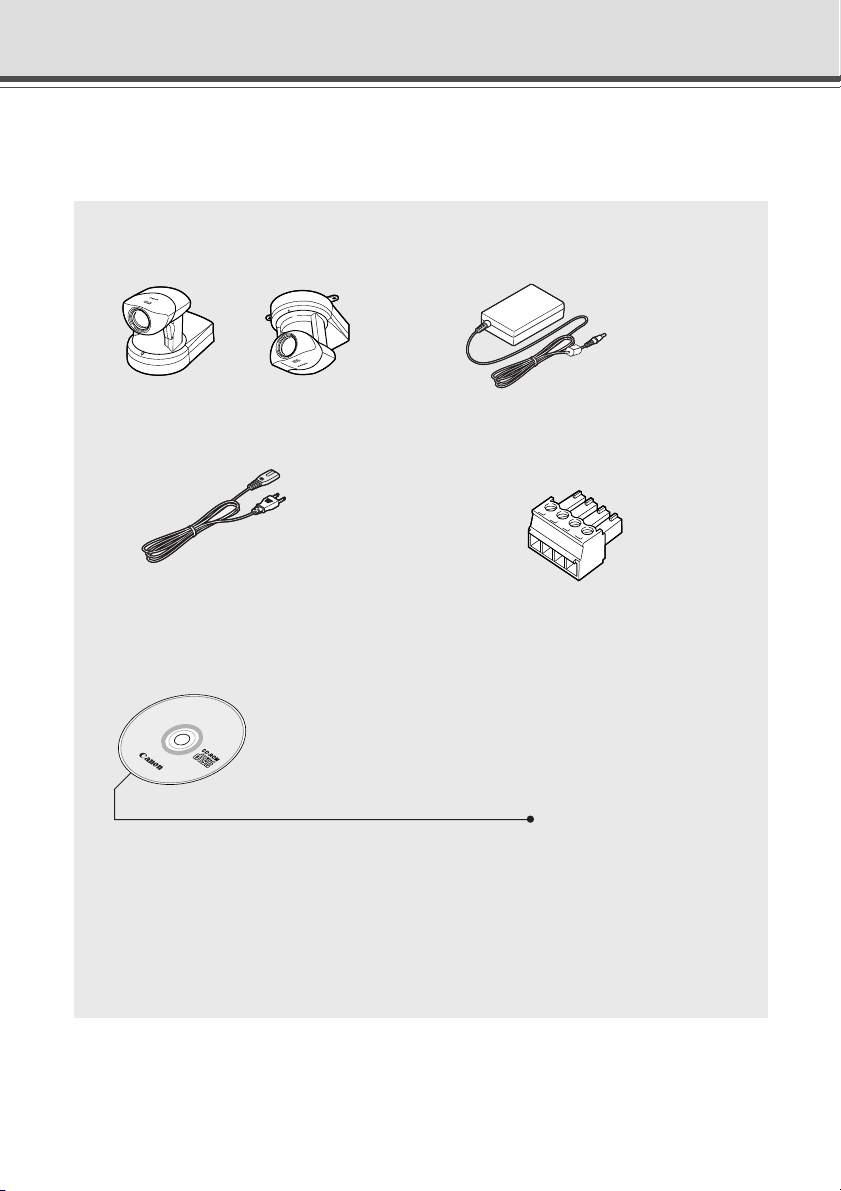
Package Contents
The VB-C10/VB-C10R package contains the following items. If any of these items is missing,
please contact the retailer from which you purchased the product.
1. VB-C10 main unit
2. AC Adapter PA-V16
(or VB-C10R main unit)
VB-C10 VB-C10R
3. AC cable (1 meter 3 ft.
* The cable length may differ depending on the
country in which the product was purchased.
5. CD-ROM
3
/
in.) 4. Plug for extenal device
32
6. User’s Manual (This document)
7. Warranty Card
CD-ROM contents
ReadMe (Notes not included in the User’s Manual)
VBIPI.exe (IP address setting tool)
MonSetup.exe (Helper Viewer version 3.20 Installer)
AdmSetup.exe (VB Administration Tools Installer)
CltSetup.exe (VBCollector Installer)
VB-C10-E.pdf (User’s Manual in PDF format)
Mon-E.pdf (Viewer Software User’s Manual)
Sample Folder
License Folder (License documents for software in the main unit)
(Set of files of sample pages)
1-8
Page 21
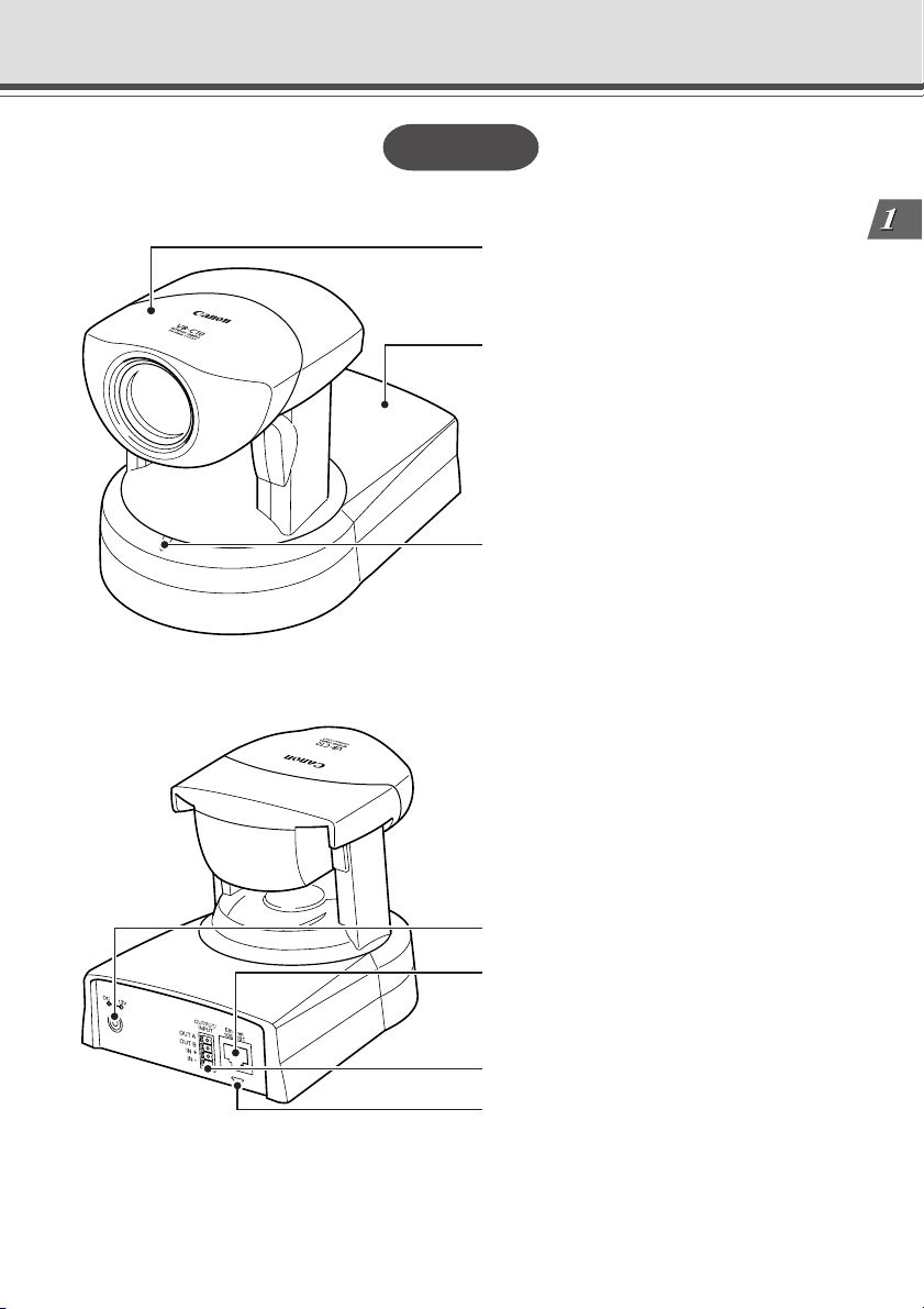
System Components and Their Operation
VB-C10
Front
Camera head
Base
Camera LED
• When power is turned on: Flashing Green
light
• During normal operation: Steady Green
light
Rear
Before Using the VB-C10/VB-C10R
Power connection socket
100/10 BT Ethernet connector
(100Base-TX, 10Base-T auto-negotiation)
External device I/O terminals
Network LED
• When connected to network : Off
• When disconnected from network: Steady
Orange light
• During communication:
Flashing Green light at 100Base-TX
Flashing Yellow light at 10Base-T
1-9
Page 22
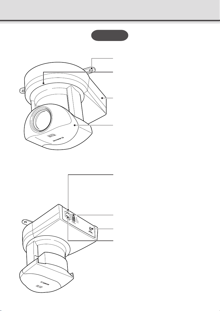
System Components and Their Operation
VB-C10R
Front
Rear
Mounting plate
Camera LED
• When power is turned on: Flashing Green
light
• During normal operation: Steady Green light
Base
Camera head
Network LED
• When connected to network : Off
• When disconnected from network: Steady
Orange light
• During communication:
Flashing Green light at 100Base-TX
Flashing Yellow light at 10Base-T
External device I/O terminals
1-10
Power connection socket
100/10 BT Ethernet connector
(100Base-TX, 10Base-T auto-negotiation)
Page 23
System Components and Their Operation
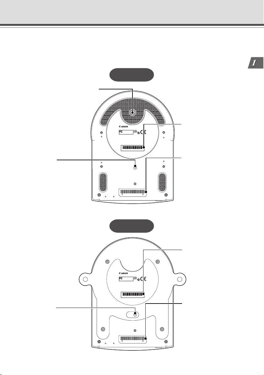
Bottom
On the bottom of the VB-C10/VB-C10R are the MAC address required for network settings, a
Reset switch that returns the factory default settings, and the serial number.
VB-C10
Screw hole for tripod mounting
Before Using the VB-C10/VB-C10R
Reset switch
You can return all settings on
the VB-C10 to the factory
default settings by holding
this button with a thin tipped
object and turning on the
power switch (→ P.8-5).
Reset switch
You can return all settings on
the VB-C10R to the factory
default settings by holding
this button with a thin tipped
object and turning on the
power switch (→ P.8-5).
VB-C10
Teste d To Comply
With FCC Standards
FOR HOME OR OFFICE USE
THIS CLASS B DIGITAL APPARATUS MEETS ALL
REQUIREMENTS OF THE CANADIAN INTERFERENCE
-
CAUSING EQUIPMENT REGULATIONS.CET APPAREIL
NUMÉRIQUE DELA CLASSE B RESPECTE TOUTES
LES EXIGENCES DU RÈGLEMENTSUR LE MATÉRIEL
BROUILLEURDU CANADA.
0123456789
CANON INC.
MADE IN JAPAN
RESET
000085228000
VB-C10R
VB-C10R
Teste d To Com ply
With FCC Standards
FOR HOME OR OFFICE USE
THIS CLASS B DIGITAL APPARATUS MEETS ALL
REQUIREMENTS OF THE CANADIAN INTERFERENCE
-
CAUSING EQUIPMENT REGULATIONS.CET APPAREIL
NUMÉRIQUE DELA CLASSE B RESPECTE TOUTES
LES EXIGENCES DU RÈGLEMENTSUR LE MATÉRIEL
BROUILLEURDU CANADA.
0123456789
CANON INC.
MADE IN JAPAN
RESET
000085228000
Serial No.
The serial number for this
unit is shown here.
MAC address
The MAC address is
required when setting the
IP address and making
other network settings.
Please make a note of it
before installing this unit
(→ P.3-3).
Serial No.
The serial number for this
unit is shown here.
MAC address
The MAC address is
required when setting the
IP address and making
other network settings.
Please make a note of it
before installing this unit
(→ P.3-3).
1-11
Page 24

1-12
Page 25

Chapter
Installation
This chapter explains how to connect the system components
and describes a sample network configuration.
Page 26
Before Using the VB-C10/VB-C10R
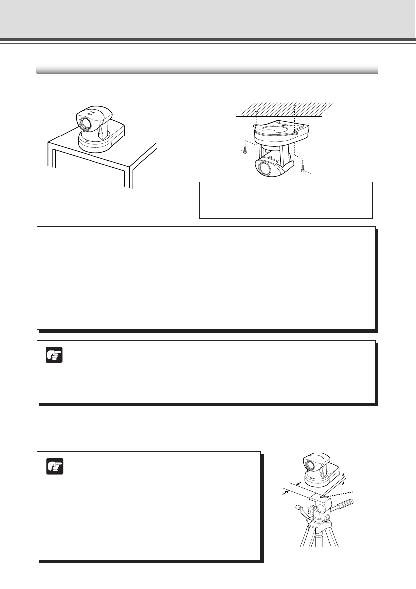
Installing the VB-C10/VB-C10R
VB-C10 Installation
Install in a flat and stable location.
Firmly tighten the 2 screws (not supplied).
Mounting plate
(Installation)
• Distance between tapped holes: 120 mm (4
• Tapped hole diameter: 6.0 mm (
• Mounting plate thickness: 1.6 mm (
VB-C10R Installation
Screw
Screw
1
/4 in.)
1
VB-C10R
/16 in.)
18
/25 in.)
a WARNING:
Install the camera securely.
● When installing the VB-C10R on the ceiling, contact your Canon dealer.
● When installing the VB-C10R on the ceiling, check that the ceiling is strong enough to
bear the weight of the VB-C10R including the mounting plate. Installation in a weak location
could result in the VB-C10R falling and causing serious injury.
● At least once a year, check for looseness in the camera installation mount. (If the optional
wide-angle converter is used, check the converter mount also.)
● The permissible camera installation angles are ±20° from the horizontal. (±15°
Note
when the optional wide-angle converter is used for the VB-C10.)
● The MAC address required when making network settings is shown on the bottom of
the VB-C10/VB-C10R (→ P.1-11). Please make a note of it before installing this unit
(→ P. 3-3).
Using a Tripod (VB-C10)
The screw for mounting a tripod is on the bottom of the VB-C10 toward the front.
● Do not overtighten the mounting screw.
Note
If excessive force is used to tighten the mounting
screw, camera head movement may be impeded,
30 mm
(1 3/16 in.)
or wider
or other malfunctions may result.
● Always use a tripod mounting screw that is less
than 6.0 mm (1/4 in.) in length. The use of screws
6.0 mm (1/4 in.) long or longer could damage the
camera. Also, the tripod seat used should be at
least 30 mm (1 3/16 in.) in diameter.
2-2
Less than
6.0 mm
1
/4 in.)
(
Mounting
screw
Page 27
Before Using the VB-C10/VB-C10R
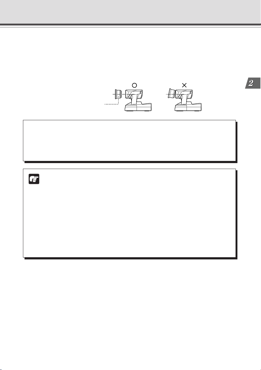
Using the Wide-angle Converter (VB-C10)
The optional Wide-angle Converter WL-37 can be used to provide wide-angle shots (approx.
0.74× the normal focal distance).
Mount the wide-angle converter correctly so that it is level and fitted securely onto the camera.
When mounted correctly, the wide-angle converter should turn roughly 3 times before stopping.
Wide-angle Converter
a WARNING:
The Wide-angle Converter WL-37 is designed specifically for the VB-C10 and cannot
be used on the VB-C10R. If the converter is used on the VB-C10R, the mount will gradually
loosen and the converter will fall off the camera.
● The camera may not operate correctly if a wide-angle converter other than the
Note
WL-37 is used.
● The permissible range of camera installation angles with the wide-angle converter
mounted on the camera is ±15° from the horizontal.
● When the Wide-angle Converter has been set for use in “Camera Settings” (→
P.3-11), the pan and tilt values change for the three functions listed below. If the
Wide-angle Converter is to be used, pan and tilt values must be determined after
the use of the Wide-angle Converter has been set in “Camera Settings”.
• Home position setting (→ P.3-12)
• View restrictions (→ P.3-12)
• Preset settings (→ P.3-15)
Installation
2-3
Page 28
Before Using the VB-C10/VB-C10R
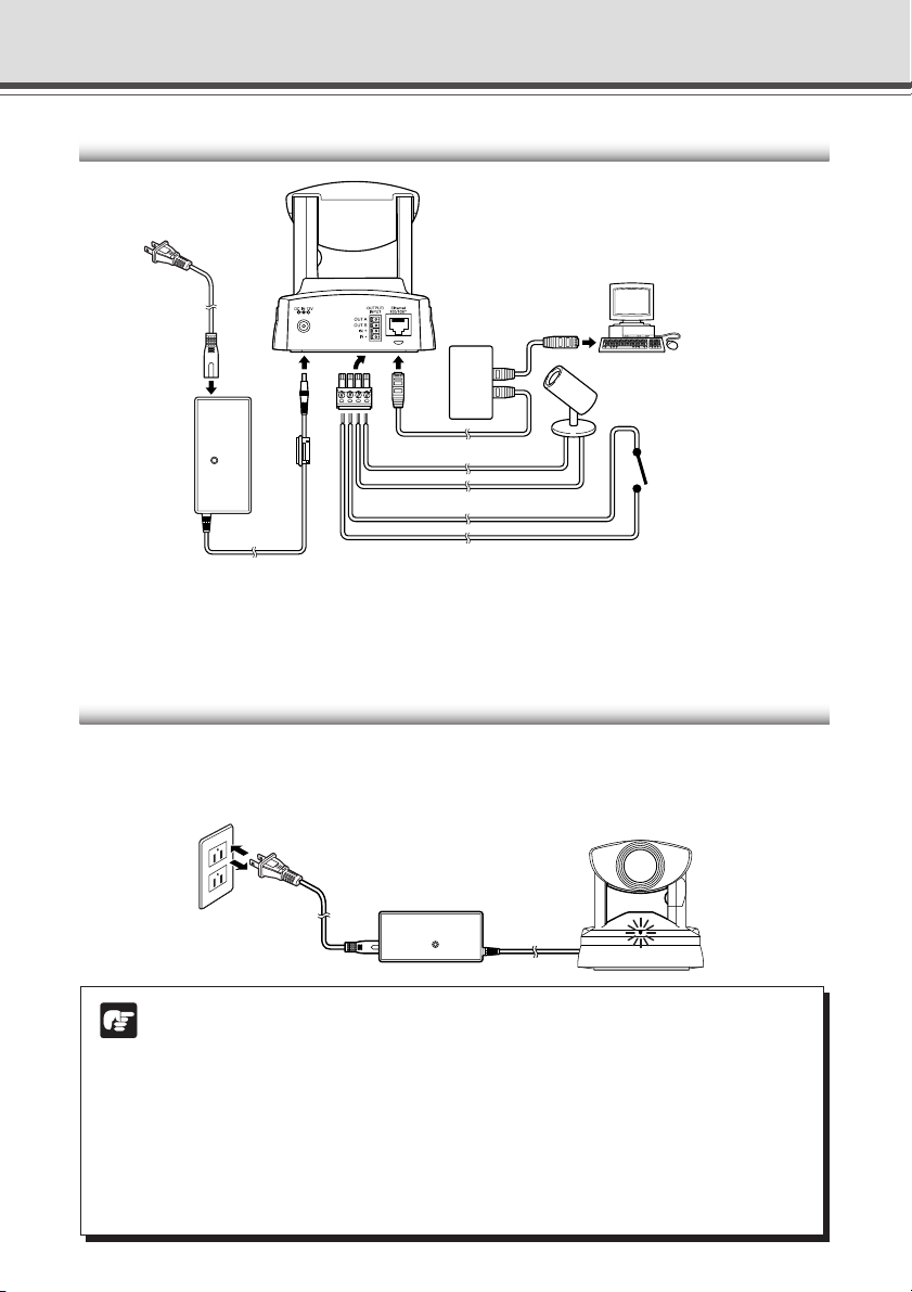
Connecting the Components
(Rear of main unit)
AC cable
Hub
PC
External output device
*
LAN
cable
AC adapter
Cables for external device
* Remove some insulation at the end of the external device cable and insert it into the plug for the
external device, then secure it by tightening the screws. See page 6-2 for examples of external
device connections.
External input device
(sensor, etc.)
Turning the Power ON and OFF
The VB-C10/VB-C10R itself does not have a power switch. You can switch the VB-C10/VB-C10R
on by plugging the AC adapter into a wall outlet. When power to the VB-C10/VB-C10R is switched
on, the Camera LED turns green.
Main unit
to AC outlet
AC adapter
AC cable
2-4
● The camera head position is automatically initialized when the power supply is
Note
turned ON from OFF.
● Never touch the camera head during initialization as this could prevent
successful initialization and cause faults.
● Wait at least five seconds before turning the power back on after shutting it off.
Turning it on too quickly may result in a malfunction. Observe the precautions
given in “a Safe Use of Equipment/a IMPORTANT SAFETY INSTRUCTIONS”
(→ P.ix).
● If the picture recording function (→ P.3-16) is being used, shutting off the
power or restarting the VB-C10/VB-C10R will cause all pictures to be deleted.
Page 29
Sample Network Configurations
This section describes some typical installation modes for the VB-C10/VB-C10R.
Be sure to assign a fixed IP address to the VB-C10/VB-C10R.
Sample LAN Environment Configuration
Provide the appropriate
server as required:
VB-C10
● HTTP (WWW)
Installation
VB-C10R
Router Router
Viewer PC
Server
Viewer PC
This example shows the VB-C10/VB-C10R connected to a LAN by Ethernet. In this configuration,
videos can be seen by viewers in the same Ethernet segment as the VB-C10/VB-C10R and by
viewers with access to that segment.
Sample Configuration in an ISP Environment
Provide the appropriate
server as required:
● HTTP (WWW)
Viewer PC
Modem
Servers
Analog line
Internet
Viewer PC
Router
ISDN/
leased line/ADSL, etc
Client receiving
images
ISDN/
leased line/ADSL, etc
Server sending
images
Router
VB-C10/VB-C10R
This example shows an environment in which the VB-C10/VB-C10R is connected to an ISP (Internet
service provider). In this configuration, videos can be seen by viewers capable of accessing the
ISP.
Bidirectional communication is required between the VB-C10/VB-C10R and the ISP, and a fixed
IP address must be set for the VB-C10/VB-C10R.
2-5
Page 30

2-6
Page 31

Chapter
Setup Procedures
This chapter describes the procedures from the initial setup
of the VB-C10/VB-C10R through to operation checking and
the method for specifying detailed settings.
The VB Administration Tools described in Chapter 4 provide
a convenient way to set view restrictions and presets.
Page 32

Preparations for Initial Setup
Once the initial setup has been completed and operation has been verified, the VB-C10/VB-C10R
can be used immediately. The diagram below shows an example of P2P connection between
the VB-C10/VB-C10R and a PC.
Installation Example
VB-C10
LAN cable
Hub
Installation Procedure
1. As shown in the diagram above, the VB-C10/VB-C10R is connected to a PC via a
hub and LAN cables (10Base-T/100Base-TX).
At this stage, please do not connect the AC adapter to the VB-C10/VB-C10R yet.
Note
2. Perform initial settings on the VB-C10/VB-C10R. (→ next page)
3. Check operation (→ P.3-6).
Check to be sure Internet Explorer 4.01 or later has been installed.
Note
3-2
Page 33

Initial Setup
1. Turn on the PC’s power switch.
The AC adapter must not yet be connected to the VB-C10/VB-C10R at this stage.
2. Insert the CD-ROM that was supplied with the VB-C10/VB-C10R into the PC’s
CD-ROM drive, and start up the “VBIPI.exe” program as follows:
1 Double-click My Computer on the desktop.
When using Windows XP, click on the “Start” button, then click “My Computer”.
2 When the CD-ROM icon appears, double-click this icon, then double-click “VBIPI.exe”.
3. When the “VB-C10/VB-C10R IP Installer” dialog box appears, connect the AC
adapter to the VB-C10/VB-C10R and turn on the power.
See “Turning the Power ON and OFF” (→ P.2-4) for how to turn on power to the VB-C10/VBC10R.
4. The VB-C10/VB-C10R’s MAC address and the currently set IP address are
displayed in the “VB-C10/VB-C10R IP Installer” dialog box.
Select a MAC address by clicking on it, then click the “Setup IP Address...” button.
● The MAC address for this unit is shown on the bottom of the VB-C10/VB-C10R
(→ P.1-11).
Tip
● The IP address 192.168.100.1 is used as the factory default setting. Please set an
IP address that suits the environment in which the VB-C10/VB-C10R is to be used.
● Internet Explorer 4.01 or later is required for the IP Installer operating environment.
Setup Procedures
3-3
Page 34

Initial Setup
5. When the “Setup IP Address” dialog box appears, enter the new IP address,
user name, and password. Then click the “OK” button.
New IP address: 192.168.101.7
User name: root
Password: VB-C10 (default setting)
The values shown here are examples only.*
* The user name cannot be changed.
* The factory default password for both the VB-C10 and the VB-C10R is “VB-C10”.
* The password can be changed at any time on the System/Network settings page (→ P.3-9).
6. The IP address that was set is displayed.
When the IP address is successfully set, it is displayed in the “VB-C10/VB-C10R IP Installer”
dialog box.
Click “Exit” to exit “VBIPI.exe.”
● The IP address “192.168.101.7” is given as an example. However, the actual IP
Note
address must be changed to match your system settings.
● Be careful to distinguish between lower-case and upper-case letters in order to
accurately enter the user name and password.
● The user name is fixed at “root” for both the VB-C10 and VB-C10R. It cannot be
changed.
● For reasons of system security, we recommend that you change the administrator
password at regular intervals.
● If network setting values are not known, please consult with the network
administrator.
● To cancel an IP address setting, click the “Cancel” button in the “Setup IP Address”
dialog box.
7. Follow steps 1 - 3 below to launch the browser and enter your user name
and password.
1 Launch the browser and enter the following URL:
http://192.168.101.7/admin/
3-4
Page 35

2 Enter the user name and password.
User name: root
Password: VB-C10 (default setting)
3 The settings title page is displayed.
Initial Setup
Setup Procedures
Initial settings are now complete.
3-5
Page 36

Checking Operation
When you have completed the initial setup, check that the VB-C10/VB-C10R works normally. Use
the sample page to simplify checking.
1. Access the sample page from the Web browser.
Example) http://192.168.101.7/sample/
Enter the value you have specified in the Initial Setup (→ P.3-3) as the IP address
(192.168.101.7).
The IP address “192.168.101.7” is given as an example. However, the actual IP
address must be changed to match your system settings.
Note
2. Click on each sample page.
If the sample page appears and the video is displayed, the VB-C10/VB-C10R is operating
normally.
* The Helper Viewer must be installed in order to appear “Helper Sample”.
Install the Helper Viewer from “MonSetup.exe” on the supplied CD-ROM.
Sample page
3-6
Example of the Java Viewer
* The picture displayed in the
viewer is an example.
We recommend that you make panorama picture settings (→ P.4-7).
Tip
Page 37

Detail Settings
Accessing the Settings Title Page
The various settings on the VB-C10/VB-C10R are specified by using a browser to access Web
pages on the VB-C10/VB-C10R. You begin by accessing the Settings Title Page.
This manual uses the IP address 192.168.100.1 (the factory default setting) below as
an example to describe the detail settings. Please enter the actual IP address that is
Note
set in your VB-C10/VB-C10R.
1. Use the browser to access http://192.168.100.1/admin.
Use the IP address specified in “Initial Setup” (→ P.3-3).
2. Enter the user name and password.
You are now asked for your user name and password. In the factory default settings, the
user name is “root” and the password is “VB-C10” for both the VB-C10 and VB-C10R.
Enter these settings.
* The password can be changed at any time on the System/Network settings page (→ P.3-9).
Settings Title Page
Setup Procedures
3-7
Page 38

Detail Settings
Settings Title Page
The various settings on the VB-C10/VB-C10R are specified by using a browser to access Web
pages on theVB-C10/VB-C10R. From this title page, you can move to each settings pages.
Settings Title Page for VB-C10/VB-C10R
“Japanese” button
Click this button to display the settings page in Japanese.
The button then changes to “English” and switches the display
back to English when clicked.
Clicking on the titles displays
each setting pages.
3-8
● Do not open multiple browser windows at the same time to change settings in
Note
parallel.
● Do not use the “Back” and “Forward” buttons in your browser to move between
settings pages. Due to the effects of caching, there are possibilities that an old
settings page will appear, settings will return to their original values, or unintended
changes will occur.
● Those settings that require the VB-C10/VB-C10R to be restarted for the changes
to take effect are marked with a red tick.
● When using the VB-C10/VB-C10R to record pictures (→ P.3-16), all recorded still
pictures are deleted when the VB-C10/VB-C10R is rebooted.
Page 39

System/Network Settings Page
This page is used to make Ethernet and password settings for the administrator.
Root Account
“Password”
Set the password here. Up to 8 alphanumeric characters,
including upper- and lower-case letters, hyphens and
underscores, can be used.
“Confirm Password”
Enter the same password as above to confirm it.
Ethernet
“IP Address”
Enter the IP address you want to assign to VB-C10/VB-C10R.
“Subnet Mask”
Enter the subnet mask specified for the network to be
connected.
“Default Gateway Address”
Set this item when you want to connect to a different
segment within the Intranet or a wide area network such as
the Internet.
*Contact the network administrator for the IP address,
subnet mask, and default gateway address settings.
Detail Settings
Setup Procedures
● Assign a fixed IP address to the VB-C10/VB-C10R.
● For system security reasons, we recommend that you change the root account at
Note
regular intervals.
● If you have forgotten the password, press the Reset switch and restore the factory
default settings (→ P.8-5).
Click the “OK” button to change the settings. To discard the changes, click the “Cancel”
button. This returns you to the settings title page.
3-9
Page 40

Detail Settings
Date/Time Settings Page
This page is used to make date and time settings.
Date and Time
“Current Camera Time”
Displays the date and time currently set on the VB-C10/VBC10R.
“New Camera Time”
One of three methods can be selected: “Synchronize with
computer time”, “Synchronize with NTP server”, or “Set
manually”.
“Synchronize with computer time”
Sets to the date and time of the computer currently
accessing the VB-C10/VB-C10R via a Web browser.
“Synchronize with NTP server”
Sets to the date and time of the NTP server when the
IP address of an NTP server has been entered.
“Set manually”
Select this item when the date and time is to be manually
entered. In the Date field, enter the year, month, and
day in yyyy-mm-dd format; in the Time field, enter the
time in hh:mm:ss 24-hour format.
For example, for January 1, 2002, 1:05:09 a.m., enter
“2002-01-01” and “01:05:09”.
“Time Zone”
Since the factory default setting uses Japan Standard Time,
please select the appropriate time zone from the list.
3-10
When selecting “Synchronize with NTP server”, enter the correct NTP server IP
address to be sure the date and time are changed correctly.
Note
Click the “OK” button to change the settings. To discard the changes, click the “Cancel”
button. This returns you to the settings title page.
Page 41

Detail Settings
Camera Settings Page
Use this page to set the camera control parameters and the video capture size and video quality.
Using VB Administration Tools is a convenient way to set view restrictions (→ P.4-12).
Camera Settings
“Camera Name”
Used in the camera selection bar in the WebView Livescope
Viewer.
“Wide Converter”
Select “Used” when a wide-angle converter is mounted on
the camera.
“Video Capture Size”
The available settings are 640 × 480, 320 × 240 and 160 ×
120.
“Video Quality”
Select an adjustment setting between 1 and 5. Higher values
give better video quality but a slower frame rate since the
amount of video data increases.
* With the VB-C10R, the displayed pan and tilt values
change.
Setup Procedures
3-11
Page 42

Detail Settings
“View Restriction”
If you tick the “Apply view restriction” option, the settings
below are enabled. Use this setting to prevent clients
from seeing certain camera angles. View restrictions
are conveniently set using VB Administration Tools
(→ P.4-12).
“Upper value, Lower value, Left value, Right value”
Sets the visible range to be provided to the user.
*Set the values so that Upper value > Lower value,
and Left value < Right value.
“Telephoto, Wide-angle”
Sets the zoom angles provided to users.
*Set the values so that the Telephoto
<
Wide-angle.
=
“Home Position”
Specify the camera settings to be used at startup. The
Pan, Tilt, and Zoom settings are valid when “Return to
Home Position when nobody has a control privilege” is
enabled.
“Pan”
Sets the pan position for the camera.
“Tilt”
Sets the tilt position for the camera.
“Zoom”
Sets the value for the camera’s angle of zoom.
“Brightness”
Sets the target value for the camera’s auto exposure
feature. Select “Brighter” if the picture is darker due
to backlight or other factor.
“Shutter Speed”
Sets the camera shutter speed. Select Auto, 1/60 or
1/100.
“Focus Mode”
Sets the focusing mode for the camera.
Select “Auto”, “Auto (for domes)”, or “Fixed at infinity”.
When the VB-C10/VB-C10R is used with an outdoor
housing, focusing on the wall of the outdoor housing
can be avoided if the Focus mode is set to “Auto (for
domes)”.
3-12
Click the “OK” button to change the settings. To discard the changes, click the “Cancel”
button. This returns you to the settings title page.
View restrictions can be set visually and more easily from the VB Administration
Tools. Please use the VB Administration Tools for making settings (→ P.4-12).
Note
Page 43

Detail Settings
View Restriction Settings
You can set the visible range by restricting the camera pan, tilt and zoom ratio (field of view angle)
settings.
Controllable range and Video Capture Range
of the video capture range
Maximum vertical extent
Extent of tilt control
Extent of pan control
+
Field of view at the
0°
maximum wide-angle setting
+-
Setup Procedures
Maximum horizontal extent of the video capture range
-
The view restriction specifies the visible range. The visible range is larger than the area in which
pan and tilt can be controlled.
Do not attempt to manually change the camera head angle.
If the camera head is accidentally moved by hand or other objects
Note
touching it, be sure to restart the VB-C10/VB-C10R by turning the
power supply OFF then ON again. The deviation from the position
that the VB-C10/VB-C10R memorizes will be corrected and the
operation will be back in order.
Range of Camera Head Movement
The figures below show the range of camera head movement from a horizontal position.
+90°
+100°
-30°
-100°
VB-C10
+170°
+10°
-90°
-170°
VB-C10R
3-13
Page 44

Detail Settings
About view restriction
● Pan and tilt range varies with the zoom ratio (field of view angle).
Tip
When you set the view
restriction, the angles of
camera movement are
automatically restricted.
If the zoom is set to wide-angle
and the angle of camera movement
remains the same, video capture
extends beyond the permitted range.
Consequently, the angle of movement
is automatically reduced.
Restricted range of visibility
f
:
4
C
6
O
4
M
m
M
U
m
N
IC
1
:
A
1
T
.
IO
4
N
2
C
.
A
8
M
E
R
A
Camera
f
:
4
C
6
O
4
M
m
M
U
m
N
IC
1
:
A
1
T
.
I
O
4
N
-
2
C
.
A
8
M
E
R
A
Angle of camera movement
Captured range
If the visible range is exceeded because the zoom is set to wide range, the camera
angle (pan, tilt) will be adjusted automatically.
Captured range
Restricted range
of visibility
f:4-64mm 1:1.4-2.8
COMMUNICATION CAMERA
Zoom out
(wide-angle)
f:4-64mm 1:1.4-2.8
COMMUNICATION CAMERA
Automatically
pans
8
.
-2
.4
:1
1
m
A
R
m
E
4
M
6
A
-
C
4
N
f:
O
I
T
A
C
I
N
U
M
M
O
C
● If the visible range is restricted, the zooming range may also be restricted.
3-14
Page 45

Detail Settings
Preset Settings Page
Use this page to specify the settings for preset camera positions provided to viewers.
Using VB Administration Tools is a convenient way to set presets (→ P.4-17).
Common Settings
“Restrict Camera Control to Presets”
VB-C10/VB-C10R camera control using Helper Viewer and
Java Viewer can be restricted to the preset angle only.
Presets 1-8
Up to 8 presets can be specified.
“Application”
Use these options to specify whether this preset can be used
only for picture recording (→ P.3-16) or is also made available
in WebView Livescope Viewer. If it is also provided in
WebView Livescope Viewer, always specify the preset name.
“Preset Name”
Enter a name consisting of up to 15 alphanumeric
characters.
“Camera Parameter”
Enter the center angle between the angles you want to set
for Pan and Tilt. Enter the viewing angle for zoom.
“Pan”
Sets the pan position for the camera.
“Tilt”
Sets the tilt position for the camera.
“Zoom”
Sets the value for the camera’s angle of zoom.
“Brightness”
Sets the target value for the camera’s auto exposure
feature. Select “Brighter” if the picture is darker due to
backlight or other factor.
Click the “OK” button to change the settings. To discard the changes, click the “Cancel”
button. This returns you to the settings title page.
Changes in presets are not applied in the viewer while it is connected.
Note
Setup Procedures
Presets can be set visually and more easily from the VB Administration Tools. Please
use the VB Administration Tools for making settings (→ P.4-17).
Tip
3-15
Page 46

Detail Settings
Picture Recording and External Device I/O Settings Page
Use this page to specify the operating condition for the picture recording function. Settings on this
page can be used to record still pictures in response to inputs from an external device (sensor,
etc.) and based on a predetermined schedule. See Chapter 6, “Using the Picture Recording
Function” (→ P.6-2) for detailed operating examples.
External Device Input
“Record pictures in response to external inputs”
Tick this option to record pictures when an input is
detected from an external device.
“Record still pictures unconditionally for every external
input event/ Record still pictures for validated external
input events during the Start-Stop times specified below”
Select “Record still pictures unconditionally for every
external input event” if pictures are to be recorded at
any time when an input is received from an external
device. If pictures are to be recorded only during
specified periods, select “Record still pictures for
validated external input events during the Start-Stop
times specified below” and set the start time, day of the
week, etc.
“Start/Stop”
Set the time when picture recording is to start and
when it is to stop.
*“Start” and “Stop” cannot be set to the same time.
“Day”
Select the day of the week when pictures are to be
“Pre-event Recording”/”Post-event Recording”
Specify how pictures are to be recorded before and after
an event is detected from an external device. There is “Preevent Recording”, for recording pictures prior to events from
an external device, and “Post-event Recording”, for recording
pictures following events. Be sure to enter at least one of
these.
If “Pre-event Recording” or “Post-event Recording” are used,
specify the interval between picture recording in 1-sec. units
or 0.1-sec. units, and enter the number of pictures to be
recorded.
“Camera Position”
Select the angle to be used in Post-event Recording. Select
“Not Specified” or from Preset 1 to 8 (→ P.3-15).
recorded. Picture recording will occur on the selected
day of the week for the period from “Start time” to
“Stop time”.
“ON event (OPEN to CLOSE)”
Pictures are recorded when ON events are detected
from an external device.
“OFF event (CLOSE to OPEN)”
Pictures are recorded when OFF events are detected
from an external device.
3-16
● When recording pictures, if you turn off the VB-C10/VB-C10R’s power switch and
Note
then reboot it, all recorded still pictures will be deleted.
● Depending on the operating status of the VB-C10/VB-C10R, still pictures may not
be recorded according to the specified intervals and the number of pictures to be
recorded. Please check the actual operation after the settings have been made.
● See “Picture Recording triggered by External Devices” (→ P.3-18).
● When recording pictures, it is convenient to do so in combination with VBCollector,
Tip
which automatically collects recorded still pictures (→ P.6-6).
Page 47

Schedule
“Record pictures according to a schedule”
When this is selected, pictures are recorded at the interval
set below. The interval can be set for every 1 to 59
seconds, every 1 to 59 minutes, or every 1 to 24 hours.
“Camera Position”
Select the angle to be used when recording pictures.
Select “Not Specified” or from Preset 1 to 8 (→ P.3-
15).
“Camera Stabilization Time”
The time set here is the time allowed for camera
operation to stabilize before it starts recording pictures.
Maximum setting is 10 seconds, enter an integer
between 0 and 10.
External Device Names
Set names for the external input/output devices used in
WebView Livescope MV.
Be sure to enter the device name.
* “External Device Input” and “Schedule” cannot be used together.
● The maximum memory capacity that can be used for recording pictures is
Note
approximately 5 MB. Available space can be checked with the Administration Tools
settings page (→ P.3-22).
● Recorded pictures are deleted when power to the VB-C10/VB-C10R is shut off
or the VB-C10/VB-C10R is restarted. Please use VBCollector to collect recorded
pictures (→ P.6-6).
● Recorded pictures are not overwritten. Once the recording picture memory
(approximately 5 MB) becomes full, recording stops. Use the Administration Tools
Settings Page (→ P.3-22) to delete recorded pictures.
Detail Settings
Setup Procedures
Click the “OK” button to change the settings. To discard the changes, click the “Cancel”
button. This returns you to the settings title page.
The amount of data for a still picture varies depending on the settings for video capture
size and video quality (→ P.3-11), and the subject. As a guide, approximately 5-10
Tip
KB is the standard when the video capture size is set to 320 × 240 and the video
quality is set to 3 (In some cases this may be exceeded). To check the amount of
data for a still picture, select “View” - “Video information” from the menu after you
start up the Helper Viewer, then check the “Size” value.
3-17
Page 48

Detail Settings
Picture Recording triggered by External Devices
Tip
ON
OFF
Picture Recording
AB CD
● Pictures can be recorded in response to ON/OFF events detected from an
external device.
ONOFF ONOFF
A: Pre-event recording for an ON event B: Post-event recording for an ON event
3-18
ON OFF
C: Pre-event recording for an OFF event D:
ON OFF
Post-event recording for an OFF event
● For A and C, recording is controlled to the pre-event recording time, and for B
and D, it is controlled to the post-event recording time.
Page 49

Detail Settings
Access Control Settings Page
From this page, you can permit access to the VB-C10/VB-C10R to specific authorized users only.
Unauthorized clients’ access is prohibited.
Authorized User Account
“Authorized User List”
Only accounts registered in this list are permitted to
connect to the VB-C10/VB-C10R. Up to 20 users can
be registered.
“Delete”
Select a user account and click the delete button to
remove the user from the list.
“Add”
You can add authorized users to the list by entering
their account name and password.
“Access permitted to listed users only”
When this option is ticked, only users registered in the
list are permitted to connect to the VB-C10/VB-C10R.
Click the “OK” button to change the settings. To discard the changes, click the “Cancel”
button. This returns you to the settings title page.
Setup Procedures
3-19
Page 50

Detail Settings
WebView Livescope Setting Settings Page
Make the various settings such as the number of simultaneous clients, frame rate, and maximum
camera control time.
WebView Livescope
“Video Transmission Port”
Set a TCP port number to be used for transmitting videos
between the VB-C10/VB-C10R and the WebView
Livescope Viewer. Enter an integer between 1 and
65535. The default setting is 65310.
“Camera Control Port”
Set a TCP port number to be used for controlling the
camera between the VB-C10/VB-C10R and the WebView
Livescope Viewer. Enter an integer between 1 and
65535. The default setting is 65311.
“Maximum Number of Clients”
Sets the maximum number of clients that can
simultaneously be connected using the WebView
Livescope Viewer. Enter an integer between 1 and 20.
“Control Queue Length”
Sets the length of the queue when multiple clients are
waiting for control privilege under the WebView
Livescope Viewer. Enter an integer between 0 and 20.
“Restrict Service Time”
When you want to set a time for videos to be
distributed to the WebView Livescope Viewer, select
this option, and specify the Start and Stop times.
With Admin Viewer, connections can also be made
and videos viewed at times other than those set
(→ P.4-24).
The maximum number is 20. When set to “0”, only the
Admin Viewer is permitted to control the camera.
“Maximum Frame Rate (fps)”
Sets the maximum number of frames captured per
second. Enter a number between 0.1 and 30. The
maximum frame rate is 30 fps.
“Maximum View Time (sec)”
Sets the maximum time the clients can view videos using
the WebView Livescope Viewer. Enter an integer
between 0 and 65535. A setting of 0 disables the time
limitation (unlimited connection time).
“Maximum Camera Control Time (sec)”
Sets the maximum time one client can keep the camera
control privilege using the WebView Livescope Viewer.
Enter an integer between 1 and 3600. The maximum
control time is 3600 seconds.
“Camera Stabilization Time (msec.)”
When the GetStillImage command (→ P.5-24) has been
requested, this setting specifies the delay to allow the
camera to stabilize before still picture is captured. Enter
an integer between 1 and 10000. The maximum delay is
10000 milliseconds.
3-20
Click the “OK” button to change the settings. To discard the changes, click the “Cancel”
button. This returns you to the settings title page.
Page 51

Miscellaneous Settings Page
Use this page to specify various other settings.
Detail Settings
HTTP Server
“HTTP Port”
Sets the TCP port number for the HTTP. Enter an integer
between 1 and 65535. The default setting is No. 80.
“Global Address for Web Pages”
If a private address has been set in the VB-C10/VB-C10R
and you want to use the router’s NAT function to have a
fixed global address assigned to the VB-C10/VB-C10R
(→ P.5-26), enter a global address here so that you can
view the sample pages (→ P.5-6).
Connection Keeping
“Send packet regularly”
When this is selected, an ICMP Echo packet is
transmitted periodically to a specified address in order
to maintain the network connection.
“Target IP Address”
Enter the IP Address of the host to which the packet is
to be sent.
“Interval (min.)”
Specify the packet transmission interval in minutes. Enter
an integer between 1 and 60.
IP Installer
“Use IP Installer”
When this is selected, the VB-C10/VB-C10R’s IP address
can be set using the “VBIPI.exe” program contained on
the supplied CD-ROM.
In the factory default settings, this item is selected.
Setup Procedures
Click the “OK” button to change the settings. To discard the changes, click the “Cancel”
button. This returns you to the settings title page.
For the packet target address in the connection function, we recommend that you
consider the impact on traffic conditions and set the IP address that is nearest after
Note
the auto dial-up router.
Router
Internet
ISDN/leased line/
ADSL, etc
VB-C10/VB-C10R
3-21
Page 52

Detail Settings
Administration Tools Settings Page
On-board File System Information
The On-board File System Information displays the used
space, free space and capacity (used space + free space)
in bytes.
Recorded Picture Information and Manipulation
The picture recording status and the number of recorded
pictures are displayed. Also, all recorded still pictures can
be deleted by clicking the “Delete” button.
Miscellaneous
“View Log Events”
Click the “View” button to see the historical log files of the
VB-C10/VB-C10R’s operation, viewers, etc.
“View Current Settings”
Displays a list of the current settings when the “View” button
is clicked.
“Reboot”
The VB-C10/VB-C10R will start again when the “Reboot”
button is clicked.
“Restore Settings”
When the “Restore” button is clicked, all settings on the
VB-C10/VB-C10R, except for network-related settings such
as the IP address, subnet mask, and default gateway
address, are restored to the factory default settings.
3-22
● When the Reset switch on the rear of the VB-C10/VB-C10R is pressed, all settings
Note
including the IP address are returned to the factory default settings (→ P.8-5).
● Since the work area for the VB-C10/VB-C10R is included in the free space on the
on-board file system, files may not be created when the free space becomes
approximately 100KB (→ P.5-8).
Click the “Cancel” button to exit from this page. This returns you to the settings title
page.
Page 53

Chapter
VB Administration Tools
This chapter describes how to use the VB Administration
Tools in order to create panoramas, set view restrictions,
make presets, view logs, and use the Admin Viewer. Although
view restriction and preset settings can be made following the
procedures described in Chapter 3, the VB Administration
Tools and their more visual environment make the settings
much easier.
Page 54

Overview of VB Administration Tools
VB Administration Tools is an application that simplifies the management and operation of the
VB-C10/VB-C10R.
VB Administration Tools comprises “VBAdmin Startup Panel” and “Panorama Creation Tool,”
“View Restriction Tool,” “Preset Setting Tool,” “Log Viewer,” and “Admin Viewer” applications.
Operations such as setting the VB-C10/VB-C10R or viewing pictures from a remote location with
special privilege, checking operating status or obtaining logs are easily performed through the
Internet or Intranet.
VB-C10 VB-C10R
VBAdmin Startup Panel (→ P.4-4)
Remote operation, setting, and information gathering
are possible through the Internet/Intranet.
Taking panorama pictures
Setting view restrictions
Setting presets
Viewing logs
Privileged viewing and operation
This is the main panel of VB Administration Tools. The tools
are started up from this panel. Install VB Administration Tools
first from the supplied CD-ROM.
Panorama Creation Tool (→ P.4-7)
This tool is used to take or create panorama pictures.
4-2
Page 55

View Restriction Tool (→ P.4-12)
This tool enables easier, more visual setting of view
restrictions. Restrictions can be set by operating the mouse
while referring to panorama previews.
Overview of VB Administration Tools
Preset Setting Tool (→ P.4-17)
This tool enables easier, more visual setting of camera preset
positions. Presets can be set by operating the mouse while
referring to panorama previews.
Log Viewer (→ P.4-22)
This tool enables viewing of operation status logs that are
output to the VB-C10/VB-C10R.
Admin Viewer (→ P.4-24)
This tool has a special privilege aimed at administrators of the
VB-C10/VB-C10R. Use it when setting presets, view
restrictions, etc.
VB Administration Tools
4-3
Page 56

Installing VB Administration Tools
Install VB Administration Tools from the CD-ROM supplied with the VB-C10/VB-C10R.
VB Administration Tools require that Microsoft Internet Explorer 5 or later be installed.
Note
1. Turn on the power to the PC.
If power to the PC is already on and Windows is running, exit all other applications before
installing VB Administration Tools.
2. Insert the CD-ROM supplied with the VB-C10/VB-C10R into the PC’s CD-ROM
drive, and follow the procedure below.
1 Double-click “My Computer” on the desktop.
When using Windows XP, click on the “Start” button, then click “My Computer”.
2 When the CD-ROM icon appears, double-click this icon, then double-click “AdmSetup exe.”
3. Perform the installation following instructions on the screen.
4. Complete installation.
When installation is complete, two icons are created on the desktop: “VB Admin Tools” and
“Admin Viewer”.
Also, When [Program]-[WebView Livescope] is selected from
the Start menu, two shortcuts are created in the same way.
4-4
Page 57

Starting Up VB Administration Tools
VB Administration Tools can be started up using the icon created on the desktop or by selecting it
from the Start menu.
○○○○○○
To Start Up...
1. If you are starting up a tool from the VBAdmin
Startup Panel, either double-click the “VB Admin
Tools” desktop icon or choose “VB Admin
Tools” from the Start menu.
2. When VB Administration Tools starts up, the
“Server Setting” dialog box appears.
To use VB Administration Tools, it must first be
connected to the VB-C10/VB-C10R.
Enter the required information in the fields and click
the “OK” button.
● Host Name
Specify the IP address or host name.
● Administrator Account : root
Enter “root” as the administrator account. (This cannot be changed.)
● Administrator Password
Enter the administrator password that has been set on page 3-9. (The default setting is
“VB-C10” for both the VB-C10 and VB-C10R.)
● HTTP Port
Enter the HTTP port number that has been set in the VB-C10/VB-C10R. (The default
setting is 80.)
● URL for settings : admin
Enter “admin” as the administrator URL. (This cannot be changed.)
● Proxy
Please consult with the network administrator for proxy settings.
“Use HTTP Proxy Server”
Select this item if the connection to the VB-C10/VB-C10R is to pass through a proxy server.
“Host Name”
Specify the host name or IP address of the proxy server.
“Port”
Enter the port number of the proxy server. (The default setting is 8080.)
VB Administration Tools
4-5
Page 58

Starting Up VB Administration Tools
3. The VBAdmin Startup Panel starts up.
The five tools—“Panorama Creation Tool”, “View Restriction Tool”, “Preset Setting Tool”, “Log
Viewer”, and “Admin Viewer”—can be started up from the Startup Panel by clicking on the
each button.
If the connection is disconnected after the VBAdmin Startup Panel has started up, choose
“Connect” from the File menu. The “Server Setting” dialog box then appears.
4-6
● The “Panorama Creation Tool”, “View Restriction Tool”, and “Preset Setting Tool”
cannot be started up simultaneously. “Log Viewer” and “Admin Viewer” can be
Tip
started up at the same time.
● If the connection to the VB-C10/VB-C10R is made through a proxy server, the
“Panorama Creation Tool”, “Log Viewer”, and “Admin Viewer” cannot be used.
Page 59

Panorama Creation Tool
The Panorama Creation Tool is used to take and create panorama pictures for the VB-C10/
VB-C10R. When they have been created, the panorama pictures can be viewed when accessed
from the viewer.
The Panorama Creation Tool is used to
take and create panorama pictures and
save them in the VB-C10/VB-C10R.
VB Administration Tools
Without a panorama picture With a panorama picture
4-7
Page 60

Panorama Creation Tool
About the Panorama Creation Tool Display Screen
An overview of the functions of the GUI that is displayed after the Panorama Creation Tool starts
up is described below.
23
1
4
5
9876
1 Display Connect Information
Displays the VB-C10/VB-C10R’s connection
information in a dialog box.
2 Reload Camera Information button
Recaptures camera information and
panorama information. If VB-C10/VB-C10R
settings were changed after this tool was
started up, this button can be used to get
the latest information.
3 Update Panorama Image button
Sends panorama pictures to the VB-C10/
VB-C10R and reloads them.
4 Captured date display
The date the panorama picture was
captured, if one was recorded, are
displayed here.
4-8
5 Panorama picture display
Shows the panorama picture that was
captured.
6 Capture button
Captures panorama pictures.
7 Remove image button
Deletes panorama pictures.
8 Position of AE Lock switching
Switches AE lock position between
“Center” and “Current position”. The AE
Lock function captures pictures based on
the brightness of the selected position.
9 Backlight adjust switching
This function adjusts backlight. When
switched on, it is effective on images that
are dark due to backlight.
Page 61

Panorama Creation Tool
Since the range that can be captured varies with the type of camera, the display
ranges of the panorama pictures are different.
Tip
VB-C10 panorama picture VB-C10R panorama picture
Capturing Panorama Pictures
Since the entire area of panorama picture is captured and displayed during capturing,
if the VB-C10/VB-C10R is accessed from the viewer and pictures are viewed, even
Note
when view restrictions (→ P.3-12) have been set, there is a possibility that third parties
that were originally not intended to see the pictures may see them. Please keep this
sufficiently in mind when capturing and displaying panorama pictures.
○○○○○○
To Capture...
1. Check the AE Lock position and the backlight
adjustment settings, then click the “Capture”
button.
2. Capturing starts.
To stop capturing while it is in progress, click the “Stop”
button.
VB Administration Tools
4-9
Page 62

Panorama Creation Tool
3. When capturing ends and the picture is
satisfactory, click the “OK” button.
Panorama creation can be discarded, or the AE lock
position or backlight adjustment settings can be
changed by clicking the “Cancel” button. When clicked,
the captured picture is discarded and the initial screen
returns.
To capture the picture again, click “Recapture” button.
Or, a square section in the displayed grid can be
captured again by double-clicking on that section.
Updating/Deleting Panorama Pictures
When capturing ends, the panorama picture is reflected when it is sent to the VB-C10/VB-C10R
and loaded.
○○○○○○
To Update...
Click the “Update Panorama Image” button. Or
choose “Update Panorama Image” from the
Server menu.
When the panorama picture is updated, the VB-C10/
VB-C10R automatically restarts and the connection with
VB Administration Tools is cut. A dialog box asking whether
or not to reconnect to the VB-C10/VB-C10R appears after
the VB-C10/VB-C10R restarts. When the “OK” button is
clicked, reconnection ocucurs. You can exit Panorama
Creation Tool while still connected or without reconnecting
to the VB-C10/VB-C10R.
○○○○○○
To Delete...
Click the “Remove image” button, and then the
“Update Panorama Image” button.
The panorama picture saved in the VB-C10/VB-C10R is
deleted.
4-10
Page 63

Panorama Creation Tool
Reconnecting
Reconnections are made when a connection with the VB-C10/VB-C10R has been cut.
To make a reconnection, choose “Reconnect” from the
File menu.
Opening/Saving Pictures
Panorama pictures can be opened from picture files or saved as picture files.
To retrieve a picture file and use it for a panorama
picture, choose “Open” from the File menu. When the
dialog box appears, select the file you want to use.
To save a captured panorama picture as a picture file,
choose “Save” from the File menu. When the dialog box
appears, select the folder where the file is to be saved
and enter the file name. In both cases, only the JPEG
format is supported.
VB Administration Tools
Displaying Connection Information
Connection information during connection with the VB-C10/VB-C10R can be displayed.
Choose “Connect Information” from the Server menu
and a dialog box showing the connection information
appears.
The IP address that was set in the VB-C10/VB-C10R is
displayed in the “Host name” (→ P.3-9). The “Video
transmission port” and the “Camera control port” that were
set on page 3-20 and the “HTTP port” that was set on
page 3-21 are all displayed.
While the Panorama Creation Tool is starting up, the video capture size (→ P.3-11)
automatically becomes 160 × 120. It returns to the original specified size when you
Tip
exit this tool.
4-11
Page 64

View Restriction Tool
The View Restriction Tool is used to set view restriction visually and more easily for the VB-C10/
VB-C10R. The viewing range is simply set using mouse operations such as dragging, while viewing
the panorama picture.
Example:
You want to distribute video of a
tourist site but you want to place
restrictions on the zoom.
→ Set the view restrictions using the
View Restriction Tool.
4-12
Only the range that was specified in the
view restriction is displayed in the viewer.
Page 65

View Restriction Tool
The View Restriction Tool Display Screen
An overview of the functions of the GUI displayed when the View Restriction Tool is started up is
given below.
23
41
5
10 9
1 Load button
Loads the view restriction values currently set in the VB-C10/VB-C10R.
2 Send button
Sends to the VB-C10/VB-C10R the current view restriction values edited with this tool.
3 Reflect set values button
Reflects in the VB-C10/VB-C10R the view restriction values that were sent by clicking the
“Send” button.
4 Cancel button
This button can be clicked during communication with the VB-C10/VB-C10R to cut the
connection.
5 Panorama Preview
Displays panorama pictures saved in the VB-C10/VB-C10R. The frames that reproduce the
values of all the view restriction settings are displayed on the panorama picture. These frames
can be displayed when “Apply the View Restriction” is selected. Also, dragging operations can
be used to change the shapes of the frames and reflect the changes in the setting values.
● View Restriction Preview frames
“Pan • Tilt Preview Frame (red)” ..................... Currently set Upper • Lower • Left • Right value
restriction area
“Wide-angle Preview Frame (green)” ............. Currently set wide-angle restriction area
“Telephoto Preview Frame (yellow)” ............... Currently set telephoto restriction area
6
7
8
VB Administration Tools
4-13
Page 66

View Restriction Tool
6 Apply the View Restriction
View restriction settings are applied when this item is selected.
7 View Restriction Values Entry box and Get Value button
The current view restriction settings are displayed in the View Restrictions Value Entry box,
and new values can be entered to change the settings. When the “Get Value” button is clicked,
the current shooting angle of the VB-C10/VB-C10R can be retrieved and reflected in the setting
values.
● View restriction setting values
“Upper value” ...... Value for the upper limit of the view restriction. The upper value of the
VB-C10/VB-C10R’s shooting angle is obtained using the “Get Value” button.
“Lower value” ...... Value for the lower limit of the view restriction. The lower value of the VB-C10/
VB-C10R’s shooting angle is obtained using the “Get Value” button.
“Left value” ......... Value for the left limit of the view restriction. The left value of the VB-C10/
VB-C10R’s shooting angle is obtained using the “Get Value” button.
“Right value” .......Value for the right limit of the view restriction. The right value of the VB-C10/
VB-C10R’s shooting angle is obtained using the “Get Value” button.
“Telephoto” ......... Value for the telephoto limit of the view restriction. The zoom value of the
VB-C10/VB-C10R’s shooting angle is obtained using the “Get Value” button.
“Wide-angle” ....... Value for the wide-angle limit of the view restriction. The zoom value of
the VB-C10/VB-C10R’s shooting angle is obtained using the “Get Value”
button.
8 Admin Viewer button
This button can be used to start up Admin Viewer.
9 Preview button
Clicking this button allows checking of the set values specified in the View Restriction Values
Entry box with the View Restriction Preview frame.
10 Status List
Displays the results of communication between this tool and the VB-C10/VB-C10R.
4-14
Edited content will not be reflected in the viewer accessed to the VB-C10/VB-C10R
at the stage when the “Send” button is used to send edited content to the VB-C10/
Note
VB-C10R. After confirming the edited content, be sure to use the “Reflect set values”
button to reflect the settings in the VB-C10/VB-C10R.
Page 67

View Restriction Tool
Setting View Restrictions
View Restrictions can be set in one of two ways. Use the method that suits your environment or
taste.
1: Retrieving values from Admin Viewer and changing settings
○○○○○○
To Make Settings...
Start up Admin Viewer and set the view restriction from the shooting angle of the VB-C10/
VB-C10R.
1 Select the “Apply the View Restriction”.
Click the “Admin Viewer” button to start it up.
VB Administration Tools
2 Use Admin Viewer to move the camera angle to
the position you want to set with the Upper,
Lower, Left, Right, Telephoto, and Wide-angle
values, then click the “Get Value” button for
each.
View restrictions set can be checked in the View Restriction
Values Entry box, or with the View Restriction Preview
frame. Set these values so that Upper > Lower, Left <
Right, and Telephoto
<
Wide-angle.
=
3 Click the “Send” button.
Check the Status List to be sure the values were sent
correctly. Then when the “Reflect set values” button is
clicked, the values will be reflected in the VB-C10/VB-C10R.
4-15
Page 68

View Restriction Tool
2: Changing Settings from the View Restriction Preview Frame
○○○○○○
To Make Settings...
The View Restriction Preview frame on the panorama picture can be used to set view
restrictions.
1 Select the “Apply the View Restriction”. Set the
view restrictions by using the mouse to move or
change the shape of the “Pan
(red)”, “Telephoto Preview Frame (yellow)”, and
“Wide-angle Preview Frame (green)” displayed on
the panorama picture.
When enlarging or reducing the Telephoto Preview and Wideangle Preview frames, however, the vertical:horizontal ratio
is fixed.
2 Click the “Send” button.
Check the Status List to be sure the values were sent
correctly. Then when the “Reflect set values” button is
clicked, the values will be reflected in the VB-C10/VB-C10R.
•
Tilt Preview Frame
4-16
● Since previews using Panorama Preview may be slightly different from the actual
pictures, after the view restrictions have been set, please check to be sure the
Tip
viewer correctly reflects the view restrictions in the actual picture. In this event,
since Admin Viewer normally operates the camera irrespective of the view restriction
settings, please choose [View Restriction]-[ON] from the Privilege menu (→ P.4-
26).
● When you want to clear the view restriction settings, remove tick from the “Apply
the View Restriction” check box, click the “Send” and “Reflect set values” buttons
to reflect in the VB-C10/VB-C10R.
● View restriction is not applied to the values with entry boxes left blank even the
“Apply the View Restriction” is selected.
● For details on view restriction settings, see page 3-12.
Page 69

Preset Setting Tool
The Preset Setting Tool more easily and uniformly sets the preset function of the VB-C10/VB-C10R.
Settings can be made using simple mouse operations such as clicking and dragging while referring
to the panorama picture.
Setting presets using the Preset
Setting Tool
VB Administration Tools
Reflecting preset settings in the viewer
4-17
Page 70

Preset Setting Tool
Preset Setting Tool Display Screen
An overview of the functions of the GUI that is displayed after the Preset Setting Tool starts up is
described below.
23
7
1 Load button
Loads the VB-C10/VB-C10R’s current preset settings.
2 Send button
Sends to the VB-C10/VB-C10R the current preset settings edited with this tool.
3 Reflect set values button
Reflects in the VB-C10/VB-C10R the preset settings that were sent by clicking the “Send”
button.
4 Cancel button
This button can be clicked during communication with the VB-C10/VB-C10R to cut the
connection.
5 Preset Selection box
Select the preset to be set.
6 For Picture Recording only
Select whether or not settings are to be used with the viewer. If selected, presets are used only
when recording pictures; if not selected, presets can be used not only for picture recording but
for the viewer as well.
41
5 6
13 12
8
9
10
11
4-18
Page 71

Preset Setting Tool
7 Panorama Preview
Displays the panorama picture saved in the VB-C10/VB-C10R. A preset preview frame (yellow)
that reproduces the preset values that were set is displayed on the panorama picture. By
dragging this frame to move it or change its shape, or by clicking on the panorama picture, the
changes can be reflected in the setting values.
Also, when a view restriction is set for the VB-C10/VB-C10R, the view restriction frame is
displayed on the panorama picture in blue or red. If the frame is red, this indicates that the
entered preset values are outside the view restriction.
8 Preset Name
A name can be assigned to the presets.
9 The Preset Values Entry box and the Brightness Selection box
The current preset settings are displayed in the Preset Values Entry box. These values can be
changed by entering new values.
● Preset Settings
“Pan” ............ Sets the pan position for the camera.
“Tilt” .............. Sets the tilt position for the camera.
“Zoom” ......... Sets the value for the camera’s angle of zoom.
● Brightness
Sets the target value for the camera’s auto exposure feature. Select “Brighter” if the picture
is darker due to backlight or other factor.
10 Get Value button
When the “Get Value” button is clicked, the current shooting angle of the VB-C10/VB-C10R is
retrieved and reflected in the settings.
11 Admin Viewer button
This button can be used to start up Admin Viewer.
12 Preview button
Clicking this button allows checking of the set values specified in the Preset Values Entry box
with the Preset Preview frame.
13 Status List
Displays the results of communication between this tool and the VB-C10/VB-C10R.
VB Administration Tools
Edited content will not be reflected in the viewer accessed to the VB-C10/VB-C10R
at the stage when the “Send” button is used to send edited content to the VB-C10/
Note
VB-C10R. After confirming the edited content, be sure to use the “Reflect set values”
button to reflect the settings in the VB-C10/VB-C10R.
4-19
Page 72

Preset Setting Tool
Setting Presets
Presets can be set in one of two ways. Use the method that suits your environment or taste.
1: Retrieving values from Admin Viewer and changing settings
○○○○○○
To Make Settings...
Start up Admin Viewer and set the shooting angle of the VB-C10/VB-C10R as a preset.
1 From the Preset Selection box, select the preset
to be set, and enter the Preset Name.
Click the “Admin Viewer” button to start it up.
2 Use Admin Viewer to move the camera angle to
the position you want to set preset angle, then click
the “Get Value” button.
Preset set can be checked in the Preset Values Entry box,
or with the Preset Preview frame.
3 Click the “Send” button.
Check the Status List to be sure the values were sent
correctly. Then when the “Reflect set values” button is
clicked, the values will be reflected in the VB-C10/VB-C10R.
4-20
Page 73

Preset Setting Tool
2: Changing Settings from the Preset Preview Frame
○○○○○○
To Make Settings...
The Preset Preview frame on the panorama picture can be used to set presets.
1 From the Preset Selection box, select the preset
to be set, and enter the Preset Name.
Set the presets by using the mouse to move or change
the shape of the Preset Preview Frame displayed on the
panorama picture. Also, when the mouse is clicked on the
picture, the Preset Preview Frame moves so that this click
point becomes the center point of the frame.
2 Click the “Send” button.
Check the Status List to be sure the values were sent
correctly. Then when the “Reflect set values” button is
clicked, the values will be reflected in the VB-C10/VB-C10R.
VB Administration Tools
● If view restrictions are to be used, be sure that the Preset Preview Frame (yellow)
does not protrude outside the View Restriction Frame (blue).
Tip
● Since previews using Panorama Preview may be slightly different from the actual
picture, after the presets have been set, please check to be sure the viewer is
correctly reflecting the presets in the actual picture.
● Once presets have been set, they cannot be deleted. If you do not want to these
presets to be used, select “For Picture Recording only” so that the presets cannot
be used in the Helper Viewer. In the Java Viewer, use of the presets can be disabled
by changing the LiveApplet parameters and disabling the Preset Selection box
display.
● For details on preset settings, see page 3-15.
4-21
Page 74

Log Viewer
The VB-C10/VB-C10R includes a feature that writes operating status to a log file and saves it. Log
Viewer simplifies the reading of log files and provides management and resolution of errors. Log
Viewer not only displays all logs, it is also capable of filtering so that only the required information
is displayed.
Viewing Logs
When Log Viewer is started up from the VBAdmin Startup Panel, it automatically retrieves the
most recent log file and displays the recent logs.
The following content is displayed in the log.
● Code
The log displays error codes. For error codes, refer to page 7-4 of the User’s Manual.
Error codes are displayed with one of four types of icons according to level.
“Information level” “Error level”
“Warning level” “Unknown”
● Date & Time
The date and time when the log was generated is displayed.
● Message
Log messages are displayed.
Using selection criteria to display logs
Logs can be filtered according to type, code, or date and time so that only the required information
is displayed.
○○○○○○
To Set Selection Criteria...
1. Choose “Filter” from the View menu.
4-22
Page 75

Log Viewer
2. The Filter dialog box appears. Set the
following selection criteria and click the “OK”
button to display only the logs that match
those criteria.
If filtering is not required, click the “Cancel” button.
[Error Type]
If logs are to be filtered according to type of error, select the “Specify Type” or “Specify Code”;
if not, select the “Not Specified”.
● Specify Type
Specifying the levels of the logs
From Error, Warning, and Information, select the error levels to be displayed.
Specifying the modules that output the logs
From Application, HTTP Sever, System, and Driver, select the output source modules to be
displayed.
● Specify Code
Specify the error code of the logs. The error codes of the logs are compared to the characters
that are entered and only logs with matching error codes will be displayed. For example, if
“A0” is entered, logs whose error codes start with “A0” will be displayed.
VB Administration Tools
[Date & Time]
● Specify Start Date & Time
Logs generated after the specified date and time can be displayed.
● Specify End Date & Time
Logs generated before the specified date and time can be displayed.
● There is no log message related to the HTTP server and the driver in the VB-C10/
VB-C10R.
Tip
● “Application” and “System” correspond to the log messages list (→ P.7-4).
● Application: Log messages related to applications (→ P.7-4)
These log messages refer to applicaion such as WebView and picture recording.
● System: Log messages related to the system (→ P.7-4)
4-23
Page 76

Admin Viewer
Admin Viewer is a viewer containing functions for managing the VB-C10/VB-C10R. Compared to
the Helper and Java Viewers, Admin Viewer lets you perform operations such as retrieve exclusive
camera control privileges, ignore view restrictions, and operate external devices.
Starting Up Admin Viewer
Click the “Admin Viewer” on the VBAdmin Startup Panel
Or double-click the “Admin Viewer” icon on the desktop.
When the Admin Livescope window appears, click the “File” then the “Connect”. The “Server
Setting” dialog box appears. Enter the following items:
● Host Name (The IP address set on the VB-C10/VB-C10R, → P.3-4)
● User Name (root, → P.3-4)
● Password (→ P.3-9)
Then click the “OK” button. The video will then be
displayed.
■ Special privileges of Admin Viewer
● Connections are also possible outside service times
(→ P.3-20).
● Connection time is unlimited.
● Exclusive camera control privileges. Invalidates control
privileges held by and requests obtained from other
viewers.
● Ignore view restrictions.
● Operates external devices.
Control Button
4-24
Since most operations and settings of Admin Viewer are common with the Helper
Viewer, basic camera control and the like are omitted here. This chapter describes
Note
only the functions and operations that are unique to Admin Viewer.
The manual for the viewer software is provided on the supplied CD-ROM (Mon-E.pdf).
About the special privileges of administrators
Since Admin Viewer has more special privileges than the Helper and Java Viewers,
please keep in mind the following points when using Admin Viewer:
● Since connection time is unlimited, please exit the Viewer after viewing.
● When a camera control privilege has been obtained, Admin Viewer forcibly continues
to obtain this privilege. After viewing, be sure to exit the Viewer or click the “Control”
button again to release these privileges.
● When making settings, keep in mind that images outside the view restrictions are
displayed also in Java and Helper Viewers that are connected simultaneously with
Admin Viewer.
Page 77

Admin Viewer
Operating External Device
Setting Notification of Changes in External Device Input Status
A message box can be displayed in the event a change in the external device input status occurs
due to a sensor connected to the VB-C10/VB-C10R or other factor.
○○○○○○
To Make Settings...
1. Choose “Setup properties” from the View menu.
2. When the “Setup properties” dialog box appears,
click the “Display option” tab.
Check to be sure the “Display notification message for
external device input” check box is selected, then click
the “OK” button.
VB Administration Tools
A message appears in the event a change occurs in the
external device input status.
If the Admin Viewer is minimized or in full screen mode, the notification message for
external device input appears after the normal display is restored. Also, this message
Note
is not displayed when the “External Device Input” dialog box (→ P.4-26) is displayed.
Displaying and Saving the External Device Input Status
The external device input status can be displayed and, when required, saved as a log.
○○○○○○
To Make Settings...
1. Choose “External Device Input” from the Privilege
menu.
4-25
Page 78

Admin Viewer
2. The “External Device Input” dialog box appears.
To save this content as a log, click the “Save” button, then
specify a file name and where it should be saved.
To clear the content in the display, click the “Clear” button.
To close the dialog box, click the “Close” button.
Operating External Device Output
The ON/OFF status of external device output to an external output device such as a light can be
changed.
○○○○○○
To Make Settings...
1. Click “Control” button to retrieve the camera
control privileges, and choose “External Device
Output” from the Privilege menu.
2. The “External Device Output” dialog box appears.
The external device output status can be changed using
the ON/OFF buttons for each terminal.
To close the dialog box, click the “Close” button.
Enabling/Disabling View Restrictions
View restrictions can be enabled or disabled when controlling the camera.
○○○○○○
To Make Settings...
Choose either “ON” or “OFF” for View Restriction
in the Privilege menu.
4-26
Page 79

Chapter
Creating Web Pages
This chapter describes how to use the VB-C10/VB-C10R to
webcast information.
Picture data can be distributed in various ways, including
displaying video or still pictures and displaying multiple
images on a Web page.
Page 80

Web Pages for Video Distribution
To distribute picture data by VB-C10/VB-C10R, you create a dedicated Web page. The viewers
that can be used with the VB-C10/VB-C10R are “Java Viewer (with or without camera control
function)” and “Helper Viewer”, and detailed parameters can be specified for each of these. You
need to determine which of these viewers is supported and create the Web page for the viewer.
Dedicated
Web server
1 Access to Web pages
HTTP (WWW) server
2 IP address information notification
Internet
3 Request for video
VB-C10
If you select a link requesting video in step 1, a file that includes the IP address information for
the VB-C10/VB-C10R is sent from the Web server in step 2. If you are using the Java Viewer, the
applet is downloaded to the viewer PC from the VB-C10/VB-C10R in response to the request in
step 3 and the video is distributed.
The VB-C10/VB-C10R includes a built-in Web server. If the content of Web pages
used for distributing videos is stored onto the flash memory in the VB-C10/VB-C10R,
Note
the VB-C10/VB-C10R can be used alone for distributing Web pages and videos over
the Web. Please refer to page 5-8 for procedures on how to save Web page data.
You can use the Language setting function for the Browser to create a multi-lingual
Web site. For example, if you set the French-language top page as index-fr.html and
Tip
the English-language top page as index.html and supply users with a URL address
terminates in slash, such as http://vb-c10/sample/, the server will transmit a file that
corresponds with the language setting for the Browser. For further information on the
Language setting function for the Browser, refer to the Browser Help.
4 Video distribution
Viewer PC
5-2
Page 81

Web Pages for Video Distribution
Features of the Java Viewers
These viewers are supplied as Java applets. They run on Web browsers that are Java-capable,
such as the Netscape Navigator and Microsoft Internet Explorer browsers. The applets are
downloaded from the camera server to the Web browser and are then run by the Web browser.
The features of the Java Viewers are described below.
● Video distribution and camera operation using the WebView-HTTP protocol.
● Penetrate firewalls to access external sites.
● Because they are automatically downloaded, the Java Viewers do not need to
be pre-installed by the client.
● Java Viewers run on a wide variety of platforms.
Because the Java applets are downloaded using the HTTP protocol when the viewer
starts up, the start up time is longer than the Helper Viewer.
Tip
Java Viewer Types
Two Java Viewers are “LiveApplet”, which has video display and camera control functions, and
“Glimpse”, which only has video display functions. Because both viewers use WebView-HTTP as
the transfer protocol, they do not require special settings to penetrate firewalls.
Creating Web Pages
Viewer Types
Viewer Name Functions
1 Displays videos from the VB-C10/VB-C10R.
LiveApplet
Glimpse
2 Allows camera control.
3 Allows overlays and superimposition of bitmaps in the video frame.
* Because video is not displayed until the viewer has finished
downloading, video display takes longer than with the Helper Viewer.
Allows the video distribution interval to be set.
* Downloading is faster than “LiveApplet” because it has only simple
functions and size is small.
5-3
Page 82

Web Pages for Video Distribution
Java Viewer
LiveApplet
Video display function
Camera control function
Click
5-4
Java Viewer
Glimpse
Video display function
Panorama Picture
Page 83

Web Pages for Video Distribution
Features of the Helper Viewer
The Helper Viewer is an application which is launched from a Web browser. Unlike the Java
Viewer, it must be pre-installed on the client's computer. The features of the Helper Viewer are
described below.
● Must be pre-installed, but once installed, start-up time is quick and operation is
stable.
● The Helper Viewer can use WebView-HTTP protocol and can penetrate firewalls
to access external sites. However, this cannot pass through with the WebViewTCP protocol (→ P.5-22).
● Can be run as a stand-alone application.
Creating Web Pages
Click
Panorama Picture
5-5
Page 84

Viewing Sample Pages
Ready-made video distribution sample pages are provided with the VB-C10/VB-C10R. Follow the
procedure below to view these pages. Refer to these pages when creating your own Web pages.
○○○○○○
Viewing the Pages
1. Launch your Web browser and enter the following URL:
http://192.168.100.1/sample/
* The underlined portion is a sample IP address. Enter the actual IP address that was set on the VB-C10/
VB-C10R.
2. The page shown below appears with links to
the other sample pages. Click on the link to
the sample page you want to view.
Examples of sample pages
JavaApplet sample 1 JavaApplet sample 2
This is a LiveApplet sample page which distributes
live videos and allows users to control the camera.
Still picture request page using JavaScript
This is a sample page which displays a live still picture.
5-6
This is a sample page which combinines LiveApplet
and Glimpse.
Page 85

Using the Java Viewer to Distribute Videos
This section describes how to use the Java Viewers to provide videos. Application examples are
also given.
Using the Java Viewer to Create a Web Page
When you use the Java Viewer, the viewer applet to be used must be incorporated into the Web
page you provide. However, this is not especially difficult. The page can be created using the
HTML normally used to include an applet.
LiveApplet
<applet codebase="http://192.168.100.1/-wvdoc-01-/LiveApplet/"
code="LiveApplet.class" archive="LiveApplet.zip"
width=450 height=380>
<param name=url value="http://192.168.100.1/">
<param name=cabbase value="LiveApplet.cab">
</applet>
Glimpse
<applet codebase="http://192.168.100.1/-wvdoc-01-/Glimpse/"
code="Glimpse.class" archive="Glimpse.zip"
width=160 height=120>
<param name=url value="http://192.168.100.1/">
<param name=cabbase value="Glimpse.cab">
</applet>
Creating Web Pages
Enter the parameters required by the applet between the <applet> -</applet> tags.
Use the <param> tag for parameters other than the common attributes for applets (codebase,
code, archive, width and height).
* The underlined portion is a sample IP address. Enter the actual IP address set for the VB-C10/VB-C10R.
5-7
Page 86

Using the Java Viewer to Distribute Videos
Saving Web Page Data
The VB-C10/VB-C10R is equipped with a Flash memory where Web page data can be saved.
Data is saved by transfering the data files using FTP. The data is placed as a file under /usr/html/
local.
Device File system URL
On-board flash
memoly
● To use a Web browser as an FTP client:
Note
Insert “root:password@” before the IP address, as in “ftp://root:password@192.168.100.1/
usr/html/local/”. The VB-C10/VB-C10R does not support anonymous FTP.
● The output performance may be lowered when there is not enough free space on
the on-board file system. Please be sure to place the minimum required amount of
data on the on-board file system (→ P.3-22).
(accessed by an ftp client) (accessed from a Web browser)
ftp://IP address/usr/html/local http://IP address/local/
5-8
Page 87

Using the Java Viewer to Distribute Videos
Example of Using the Java Viewer to Create a Web Page
This section describes an example in which the Java Viewer is used to create a Web page.
Use this example to create your own original Web page.
Embed the Java Viewer, and Display a Text in a Separate Frame
1 Frame settings
2 The text displayed in a
separate frame
3 Frame with the embedded
Java Viewer
Writing IP Addresses
Using the Web server functions built into the VB-C10/VB-C10R, IP addresses can be
Tip
expressed as <_I_P_A_D_D_R_> (all upper-case characters, including the angle
brackets) in the three file types (html, wvh and wvp) used by the Web server in the
VB-C10/VB-C10R.
Since <_I_P_A_D_D_R_> is replaced with the actual address when the VB-C10/
VB-C10R is accessed, the Web page does not need to be changed even when the
VB-C10/VB-C10R’s IP address is changed. NAT can also be supported by specifying
a global address for the Web page (→ P.5-26).
Creating Web Pages
5-9
Page 88

Using the Java Viewer to Distribute Videos
1 sample.htm
<html>
<head>
<title>SampleSite LiveApplet</title>
</head>
<frameset rows="70,*">
<frame src="header.htm">
<frame src="lvappl.htm">
</frameset>
</html>
2 header.htm
<html>
<head>
<title>LiveApplet comment</title>
</head>
<body>
<center><h1>LiveApplet</h1></center>
</body>
</html>
3 lvappl.htm
5-10
<html>
<head>
<title>LiveApplet</title>
</head>
<body>
<applet codebase="http://192.168.100.1/-wvdoc-01-/LiveApplet/"
code="LiveApplet.class" archive="LiveApplet.zip"
width=450 height=380>
<param name=cabbase value="LiveApplet.cab">
<param name=url value="http://192.168.100.1/">
</applet>
</body>
</html>
* The underlined portion is a sample IP address. Enter the actual IP address set for the VB-C10/VB-C10R.
Page 89

Using the Java Viewer to Distribute Videos
Using Glimpse and LiveApplet Together
This section describes how to create a Web page that allows clients to use Glimpse to download
quickly and view live video at a low frame rate, and then use LiveApplet to view video at a high
frame rate and control the camera when they find videos they are particularly interested in.
1 Glimpse embedded in the
page
Click the button to display
the page in which LiveApplet
is embedded.
Creating Web Pages
2 Pop-up LiveApplet window
5-11
Page 90

Using the Java Viewer to Distribute Videos
1 glimps.htm
<html>
<head>
<script language="JavaScript">
<!-function clicked(btn) {
url = btn.name
window.open(url,"LiveApplet","width=490,height=400")
}
// -->
</script>
<title>Glimpse</title>
</head>
<body>
<table>
<form name="form">
<tr><td><center>
<applet codebase="http://192.168.100.1/-wvdoc-01-/Glimpse/"
code="Glimpse.class" archive="Glimpse.zip"
width=160 height=120>
<param name=cabbase value="Glimpse.cab">
<param name=url value="http://192.168.100.1/">
</applet>
</center></td></tr>
<tr><td><center>
<input type="Button" name="popup.htm" value="click me"
onClick="clicked(this)">
</center></td></tr>
</form>
</table>
</body>
</html>
2 popup.htm
5-12
<html>
<head>
<title>LiveApplet</title>
</head>
<body>
<center>
<applet codebase="http://192.168.100.1/-wvdoc-01-/LiveApplet/"
code="LiveApplet.class" archive="LiveApplet.zip"
width=450 height=380>
<param name=cabbase value="LiveApplet.cab">
<param name=url value="http://192.168.100.1/">
</applet>
</center>
</body>
</html>
* The underlined portion is a sample IP address. Enter the actual IP address set for the VB-C10/VB-C10R.
Page 91

Using the Java Viewer to Distribute Videos
Providing “LiveApplet” without Camera Control
This section describes how to create a Web page that only displays live video and has no camera
control GUI for situations where you want to prohibit camera control.
<applet ...... width=320 height=240>
<param name=controller_style value="none"> ............................................................ 1
1 specifies the camera control user interface.
“normal”: The usual style.
“preset_only”: Preset operation only is displayed.
“none”: Not displayed.
Creating Web Pages
Modifying the Startup and Disconnection Screens
You can modify the image files (JPEG or GIF image files) shown in the startup and disconnection
screens.
Nothing Specified
Startup screen Disconnection screen
5-13
Page 92

Using the Java Viewer to Distribute Videos
Certain Images Specified
Startup screen Disconnection screen
If no particular image is specified, the “connecting to hostname” (when the hostname parameter is
specified) or “now connecting” animation is displayed at startup and the “disconnected hostname”
(when the hostname parameter is specified) or “disconnected” is displayed at disconnection.
You can modify the screens to show any image by providing images for the startup and
disconnection screens and setting the parameters. The image size is automatically adjusted to
the size specified in the video_width parameter. The display time for the specified screen at startup
can also be specified.
<param name=open_image value="/local/images/opening.jpg"> ............................. 1
<param name=open_image_time value="3000"> ........................................................ 2
<param name=close_image value="/local/images/closing.jpg"> .............................. 3
1 specifies the file name for the startup image screen.
2 specifies the display time for the startup image screen (in milliseconds).
3 specifies the file name for the disconnection image screen.
You must use the absolute path name (name that begins with “/”) to specify the path
for the image file displayed (→ P.5-8).
Note
● At startup, the default character string that is displayed while a connection to the
VB-C10/VB-C10R is being established is “now connecting”, but there is also a
Tip
parameter called “connect_msg” for changing this character string. For additional
parameters for changing display character strings, see page 5-17.
● If the user’s service time has been set (→ P.3-20), screen images are not displayed
outside the specified time.
5-14
Page 93

Using the Java Viewer to Distribute Videos
Displaying the Host Name, Frame Count and Other Information on the Video Screen
12 3
4
<param name=show_fps value="on"> 1
<param name=show_counter value="on"> 2
<param name=hostname value="CANON">
<param name=show_hostname value="on">
<param name=comment value="VB-C10 site">
<param name=show_comment value="on">
1 specifies whether the frame rate is displayed on the screen.
“on”: Displayed.
“off”: Not displayed.
2 specifies whether the frame count is displayed on the screen.
“on”: Displayed.
“off”: Not displayed.
3 specifies the host name (any text string) to be displayed on the screen and whether the host
name is displayed.
“on”: Displayed.
“off”: Not displayed.
4 specifies a comment to be displayed on the screen and whether the comment is displayed.
“on”: Displayed.
“off”: Not displayed.
3
4
Creating Web Pages
5-15
Page 94

Using the Java Viewer to Distribute Videos
Displaying Bitmap Images on the Video Screen
Sample transparent GIF
<param name=superimpose value="/local/logos/newlogo.gif,0,0">
* The underlined portion “x,y” specifies the display position. When x,y = 0,0, the image is displayed in the top
left corner. If “x,y” is omitted, the image is displayed in the center of the frame.
Specifying the Background Color
<html>
<body bgcolor=#cccccc>
<applet codebase=http://...code="LiveApplet.class" width=450 height=380>
<param name=url value="http://192.168.100.1">
<param name=bg_color value="#cccccc">
</applet>
</body>
</html>
* The underlined portion is a sample IP address. Enter the actual IP address set for the VB-C10/VB-C10R.
Pasting a Picture to the Background
<param name=bg_image value="/local/images/back.gif"> ........................................ 1
<param name=image_offset value="0,0"> ................................................................... 2
1 specify the displayed picture file.
2 specify to display it at x,y (underlined portion).
5-16
Page 95

Using the Java Viewer to Distribute Videos
Java Viewer Parameters
You can specify applet parameters to provide an applet tailored to modify the behaviour or
appearance of applets. Refer to the table below to ensure that you thoroughly understand the
parameters.
LiveApplet
Parameter Name
bg_color Yes
close_image Yes
comment Yes
gui-type Yes
hostname Yes
open_image Yes
open_image_time
show_capture Yes
show_comment Yes
show_counter Yes
show_fps Yes
show_hostname
show_panobutton
Omissible
Use this parameter to set the background color. The parameter specification format
is“#RRGGBB” (values between 0 and 255 for each component color expressed
as a hexadecimal).
Eg. White: “#FFFFFF”, Grey: “#AAAAAA”, Green: “#00FF00”
If this parameter is omitted, the default background color is used.
You can use this parameter to specify the screen displayed in the video display
window at the time of disconnection. Specify the name of a JPEG or GIF file. If
this parameter is omitted, the default disconnection screen is displayed.
This parameter specifies the comment text string displayed as an overlay on the
applet. If this parameter is omitted, no comment is displayed.
Specifies whether the panorama window should be pop-up displayed or embedded
in the page. Specify “embed” for making it an embedded display. When specifying
“embed”, the Width and Height of the applet tags must be specified a little larger
(Eg. width=500; height=660).
This parameter specifies the host name displayed in the applet. This value is
used as the host name in messages displayed during connection, etc. If this
parameter is omitted, no host name is displayed.
You can use this parameter to specify the screen that appears in the video display
window until the first video image appears. Specify the name of a JPEG or GIF
file. If this parameter is omitted, the default startup screen is displayed.
When a startup screen is specified in the “open_image” parameter, this parameter
specifies the display time. The time is specified in milliseconds (1/1000 sec.),
Yes
and the default value is 0. The image is displayed until the first video frame
appears. Values from 0 to 30000 (30 seconds) can be specified.
This function specifies whether the Snapshot button is displayed. Specify “on” or
“off”. The default value is “on”. The button is always displayed unless “off” is
explicitly specified.
This function displays the comment as an overlay on the video image. Specify
“on” or “off”. The default value is “off”.
This function displays the frame count as an overlay on the video image. Specify
“on” or “off”. The default value is “off”.
This function displays the frame rate as an overlay on the video image. Specify
“on” or “off”. The default value is “off”.
This function displays the host name as an overlay on the video image. Specify
Yes
“on” or “off”. The default value is “off”. Note that this parameter is only valid if the
“hostname” parameter is specified.
Specify whether or not to display the panorama window pop-up button. The default
Yes
value is “on”.
Description
Creating Web Pages
5-17
Page 96

Using the Java Viewer to Distribute Videos
Parameter Name
superimpose Yes
url No
video_width Yes
auto_connect Yes
bg_image Yes
click_action Yes
connect_msg Yes
controller_style Yes
disconnect_msg
error_msg Yes
font_size Yes
image_offset Yes
no_connect_msg
overlay_font_color
show_logo Yes
too_many_msg Yes
Omissible
Yes
Yes
Yes
Description
This function displays a bitmap image as an overlay on the video image. Specify
the image using the “bitmap-filename,x,y” format. Use the GIF format for bitmap
images (transparent GIFs supported). The “x,y” parameters specify the coordinates
of the bitmap image position on the video frame. If “x,y” is omitted, the image is
displayed in the center of the video frame.
Specify the URL of the HTTP server for applet access. Specify the IP address
and port number that match those specified in the codebase attribute.
This parameter specifies the video image display size (in pixels). Specify the
width. The display sizes are 80 to 640, and any value can be set as the width.
The height is calculated as 3/4 of the specified width. Eg. video_width=“240”
(height=240 × 3/4=180.)
Specifies whether or not connection to the camera server should be established
at the same time that the applet starts up. Select “on” or “off”. When “on” is selected,
connection is established when the applet starts up and moving pictures are
displayed. With “off”, the connection is not established when the applet starts up
and the character string that was specified with the “no_connect_msg” parameter
is displayed. The “connect()” method is called up to establish connections.
The picture displayed in the background of LiveApplet can be specified. A JPEG
or GIF file can be specified. The WebView Livescope logo is not displayed if
specified. If not specified, the default picture is used.
Specifies behavior when a moving picture display area is clicked. “pt” specifies
pan and tilt; “none” specifies no reaction. The default is “pt”.
Specifies the character string that is displayed while connection to the camera
server is being established. The default is “now connecting”.
Specifies the GUI style for controlling the camera. “normal” specifies the usual
GUI style; “preset_only” specifies preset operation only; “none” specifies that the
entire GUI will not be displayed. With “preset_only”, only the Control Start button,
the Camera Control Status window, the Preset Selection bar, and the Snapshot
button are displayed.
Specifies the character string that is displayed when the connection to the camera
server is cut. The default is “disconnected”.
Specifies the character string that is displayed when connection to the camera
server has failed. The default is “can’t connect”.
Specifies the display size for connect_msg, disconnect_msg, error_msg,
no_connect_msg, and too_many_msg. The default makes size dependent on
the display area.
Specifies the display position of the picture file specified at bg_image. With the
upper left coordinates of the picture at “0,0” and the right direction given as x and
the down direction as y, image_offset is specified as “x,y”. The default is “335,0”.
Specifies the character string to be displayed following applet startup when
auto_connect is “off”. The default is “no connection”.
Specifies the color of the character string specified for “comment” and “hostname”.
The color is specified at “#RRGGBB”. The default is yellow.
Specifies whether or not the WebView Livescope logo should appear in the upper
right of the screen. It appears if show_logo is “on” and does not appear if it is
“off”.
Specifies the character string that is displayed when connection to the camera
server fails because the limit on the number of connections was exceeded. The
default is “too many clients”.
5-18
Page 97

Glimpse
Parameter Name
comment Yes
hostname Yes
show_counter Yes
show_hostname
sleep Yes
url No
auto_connect Yes
connect_msg Yes
disconnect_msg
error_msg Yes
font_size Yes
no_connect_msg
Omissible
Yes
Yes
Yes
Using the Java Viewer to Distribute Videos
Description
This parameter specifies the comment text string displayed as an overlay on the
applet. If this parameter is omitted, no comment is displayed.
This parameter specifies the host name displayed in the applet (alphanumeric
character only). This value is used as the host name in messages displayed
during connection, etc. If this parameter is omitted, no host name is displayed.
This function displays the frame count as an overlay on the video image. Specify
“on” or “off”. The default value is “off”.
This function displays the host name as an overlay on the video image. Specify
“on” or “off”. The default value is “off”. Note that this parameter is only valid if the
“hostname” parameter is specified.
This parameter specifies the interval (in milliseconds) at which the screen is
updated. If this parameter is omitted, the screen is updated at 5-second intervals.
Because the Glimpse applet is designed to be used for displaying multiple sites
as a list, this parameter is provided as a means of reducing the processing load.
Intervals between 0 and 300,000 ms (5 minutes) can be set. If 0 is specified, the
interval is not adjusted.
Specify the URL of the HTTP server for applet access. Specify the IP address
and port number that match those specified in the codebase attribute.
Specifies whether or not connection to the camera server should be established
simultaneously with applet startup. Specify either “on” or “off”. When “on”, a
connection is established simultaneously with applet startup; when “off”, no
connection is established when the applet starts up and the character string
specified for no_connect_msg is displayed. The connect() method is called up in
order to make connections..
Specifies the character string to be displayed while a connection to the camera
server is being established. The default is “now connecting”.
Specifies the character string to be displayed when a connection to the camera
server is disconnected. The default is “disconnected”.
Specifies the character string to be displayed when an attempt to connect to the
camera server has failed. The default is “can’t connect”.
Specifies the font size for connect_msg, disconnect_msg, error_msg, and
no_connect_msg when these messages are displayed. The default is to depend
on the display area.
Specifies the character string to be displayed after the applet starts up, if “off” is
specified for auto_connect. The default is “no connection”.
Creating Web Pages
5-19
Page 98

Using the Java Viewer to Distribute Videos
Applet Tag Descriptions
Attribute Name
code No
codebase No
width No
height No
archive Yes Specify LiveApplet.zip or Glimpse.
Omissible
This parameter specifies the applet file name. Enter “LiveApplet.class” or
“Glimpse.class”. If this parameter is not specified correctly, the applet (LiveApplet
or Glimpse) is not downloaded.
This parameter specifies the directory that contains the applet.
http://HTTP server IP address: port number/directory/
If this parameter is not specified correctly, the applet (LiveApplet or Glimpse) is
not downloaded.
Directories are fixed for each applet.
Directory (LiveApplet)=-wvdoc-01-/LiveApplet
Directory (Glimpse)=-wvdoc-01-/Glimpse
This parameter specifies the size of the area acquired for the applet (in pixels).
For LiveApplet, if the value specified is smaller than the LiveApplet drawing area,
the applet may not be displayed correctly. If the camera control function GUI is to
be added (controller_style=normal), add about 130 to the value.
Eg. For an image size of 320 × 240, width=450.
For Glimpse, because the areas used for the applet and for the video display are
the same size, specify the same value as the image width.
Eg. For an image size of 320 × 240, width=320.
As for width. For LiveApplet, add around 140.
Eg. For an image size of 320 × 240, height=380.
For Glimpse, specify the same value as the image height.
Eg. For an image size of 320 × 240, height=240.
Description
5-20
When specifying an address included in the codebase attribute of the applet tag and
a URL parameter of the applet, specify one that can be accessed from the client’s
Tip
computer. This is particular necessary when using NAT.
Page 99

Using the Helper Viewer to Distribute Videos
This section describes how to use the Helper Viewer to provide videos. Application examples are
also given.
If a client is using the Helper Viewer to receive videos, the video sender must set up the Web
server and create the necessary wvh files.
● The settings below are not required if the VB-C10/VB-C10R’s built-in Web server
is used.
Tip
● See page 5-8 for saving Web page data.
Setting Up the Web Server
Set up the Web server to be used for providing Web pages. Add the MIME type to the Web server
software and specify the extension. Refer to the manual for your Web server software for details.
MIME type video/x-webview-h
Extension wvh
For Apache
In the settings for added the MIME type in Apache, edit the “mime.types” file in the “conf”
directory.
● Use the following syntax to add the required MIME type to the computer:
type/subtype extention
Creating Web Pages
● The settings for WebView Livescope are as follows:
video/x-webview-h wvh (Helper settings)
If the MIME setting is not specified correctly for the Web server, you may not be able
to launch the Helper Viewer. Be sure to specify the setting correctly.
Note
5-21
Page 100

Using the Helper Viewer to Distribute Videos
Creating wvh Files
This section describes how to create the wvh file required for launching the Helper Viewer
application.
1. Use a text editor or similar program to create a new text file and type the
following type of code in the file:
(Example) 192.168.100.1 65310
192.168.100.1 65311
wvhttp:192.168.100.1 80
● The first line gives the IP address (or host name) of the VB-C10/VB-C10R and the TCP port
number used for the video transmission. The default setting is 65310 (→ P.3-20). The default
setting will be used if no particular value is specified.
● The second line gives the IP address (or host name) of the VB-C10/VB-C10R and the TCP
port number used for the camera control. The default setting is 65311 (→ P.3-20). The
default setting will be used if no particular value is specified.
● The third line gives the setting for the Helper Viewer to use HTTP protocol. After “wvhttp:”,
type in the IP address of the VB-C10/VB-C10R and “80” as the HTTP port number. As a
result of this, you will be able to view video from the VB-C10/VB-C10R through firewalls.
* Type in the actual IP address (or host name) set for the VB-C10/VB-C10R.
2. After you save the text file and quit the text editor program, create a wvh file
by changing the file name and extension. Be sure to add the “.wvh” extension,
as in “WebView.wvh”.
Helper Viewer supports WebView Livescope protocol and HTTP protocol.
● WebView Livescope protocol:
Tip
Cannot be viewed through firewalls. This protocol is primarily for clients who are
connected directly to the Internet.
● HTTP protocol:
In general, this protocol is used with Web browsers. By using this protocol, clients
inside firewalls can view video by penetrating fire walls. The Java Viewer also
uses this protocol.
5-22
 Loading...