

Page 1
*+,;,
VISUAL COMMUNICATION SYSTEMS
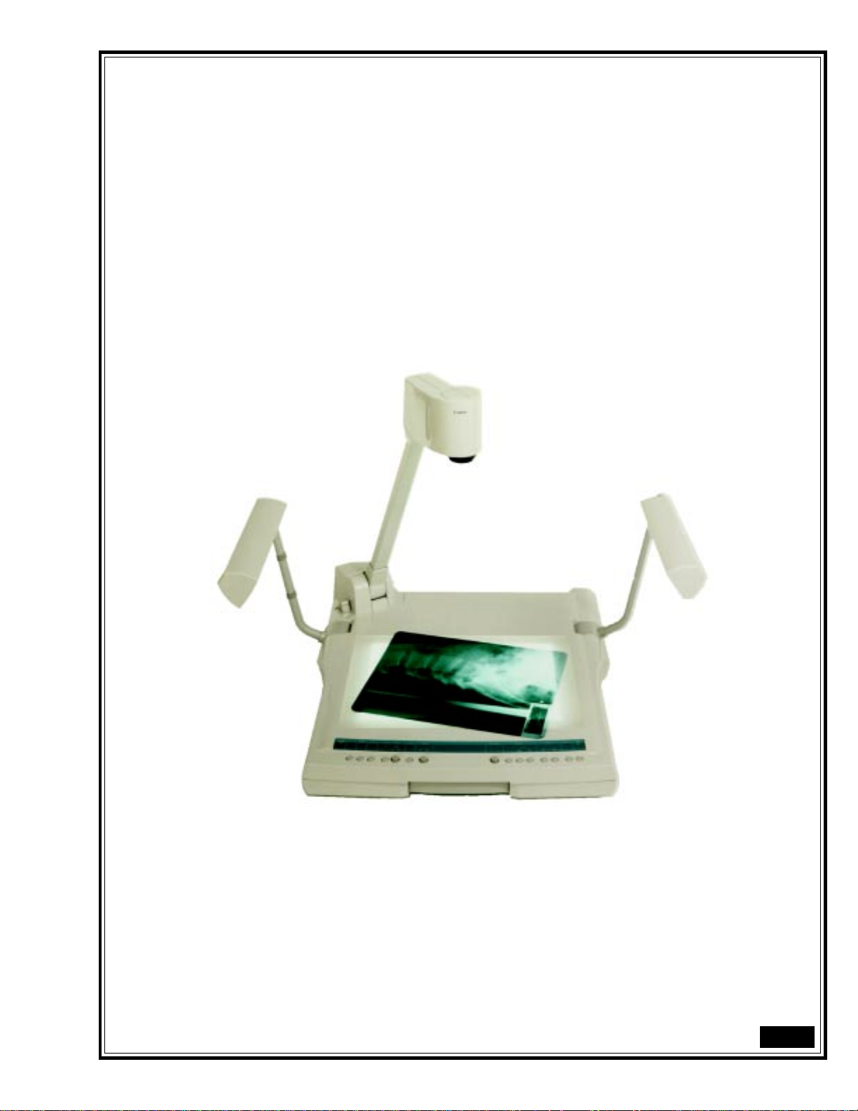
RE-350
RE-350
Video Visualizer
Control Interface Commands
v1.0
1
Page 2

Control Interface Command Index
1.0 Operations and Functions
1.1 Panel Diagrams............................................................................................................................................. 3
1.2 Description of the Panel Functions .......................................................................................................... 4–8
1.3 Operational Procedures Overview........................................................................................................... 9–13
1.4 The Default Setting of Each Function.........................................................................................................14
1.5 Meaning of Each LED Status ...................................................................................................................... 14
1.6 Control Protocol ........................................................................................................................................ 15
1.7 Packet Discrimination Code Assignment.....................................................................................................15
1.8 Data Packet Configuration.......................................................................................................................... 16
“Control Command Packet” Format.......................................................................................................... 16
“C-response Data Packet” Format.............................................................................................................. 16
“Event Data Packet” Format...................................................................................................................... 16
“E-response Data Packet” Format.............................................................................................................. 16
“FP Data Packet” Format .......................................................................................................................... 16
1.9 Operational Flow Charts....................................................................................................................... 17–18
Command Communication Flow Pattern ................................................................................................... 17
Event Packet Flow Pattern ......................................................................................................................... 17
[N
OTIFICATION
] Mode Flow Pattern............................................................................................................ 18
2.0 Control Command and Packet Tables
2.1 Camera Control Commands Table.............................................................................................................. 19
2.2 System Control Commands Table............................................................................................................... 20
2.3 “C-response Data Packet” Table................................................................................................................. 21
2.4 “Event Data Packet” Table ......................................................................................................................... 22
2.5 “E-response Data Packet” Table ................................................................................................................. 23
2.6 “FP Data Packet” Table.............................................................................................................................. 24
3.0 Description of Command Data Packet
3.1 Zoom ................................................................................................................................................... 25–29
3.2 Focus ................................................................................................................................................... 30–32
3.3 White Balance............................................................................................................................................. 33
3.4 Exposure .................................................................................................................................................... 34
3.5 Detail ......................................................................................................................................................... 35
3.6 Negative/Positive.......................................................................................................................................36
3.7 Color/B&W............................................................................................................................................... 37
4.0 System Control Commands
4.1 Detailed System Control Commands .................................................................................................... 38–54
5.0 Control Cable Pin Assignments
5.1 RS-232C Control Cable Pin Assignments ............................................................................................. 55–57
6.0 Timing Charts
6.1 RTS/CTS Flow Control Timing Chart....................................................................................................... 58
6.2 RTS Flow Control Timing Chart ................................................................................................................ 59
Appendix A – Disk Information......................................................................................................................... 60–63
2
Page 3
1.0 Operations and Functions
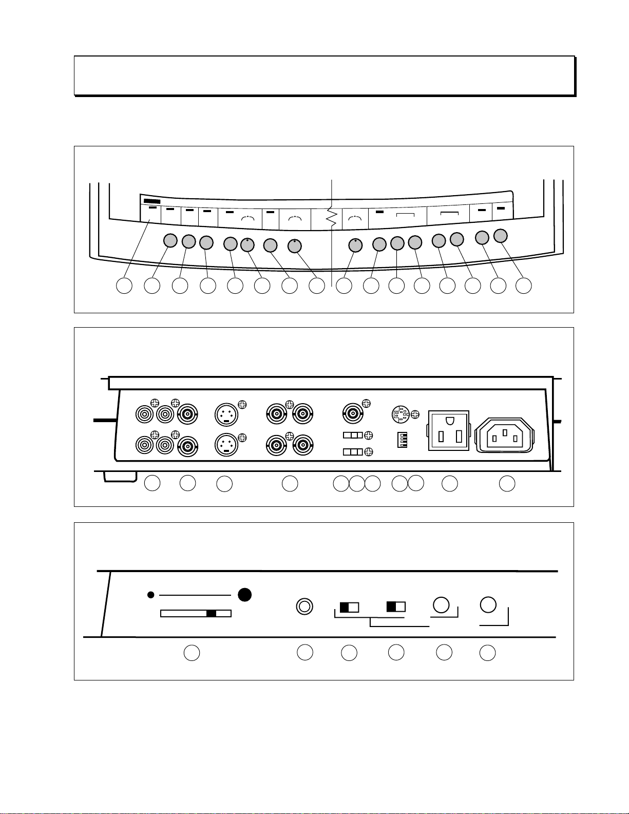
1.1 Panel Diagrams
Operation Panel
1
OUT
IN
RS-232
POWER
CONTROL
LOCAL
CONTROL
DISABLED
2
3
Audio Video
RLRL
21
IN
S
E
22
BACK
LIGHT
P
U
T
NEGA
L
E
C
T
4
WHITE BALANCE
MANUAL
AUTO
RED
5
BLUE
DETAIL
B/W
SOFT
HARD
8
7
6
EXPOSURE
-
9
FOCUS
MANUAL
AUTO
NEAR
+
11
10
ZO
WIDE
FAR
12
LIGHTS
M
O
TELE
16151413
Rear Panel
S-Video
23
RGB OUT
RG
B
SYNC
24
EXT
75Ω
ON
SYNC
ON
25 26
OFF
OFF
27
RS-232C
24/96
100/60
ID/0
ID/1
29
AC Outlet
AC Inlet
30 3128
MIC LEVEL
32
Side Panel
MIC
33
34
3 41 2
SC
35 36
H
PHASE
37
3
Page 4
1.2 Description of the Front and Rear Panel Functions
Button/
Control Knob
RS-232
CONTROL
(Button)
†
Key
2
Function
N-LINE
Switches the mode from [O
Mode to [O
In the [O
on line’. In the [O
N-LINE
FF-LINE
] Mode.
] Mode the RE-350 will send the “Event Data Packet” for ‘Request
N-LINE
] Mode or [N
] Mode to [OFF-L
OTIFICATION
“Event Data Packet” for ‘Request off line’.
[OFF-L
INE
] Mode
The RE-350 will reject the RS-232 commands from the PC except for the [ON-L
Mode command or the [N
to [OFF-L
LED
[ON-L
INE
] Mode when it is to be controlled from the front panel. The RS-232
will be off.
INE
] Mode
OTIFICATION
] Mode command. The RE-350 should be set
The RE-350 will reject every input from the front panel except from the {RS-232
Control}† button and will accept only RS-232 command data packets from the PC.
The RS-232 LED will be on.
[N
OTIFICATION
] Mode (Used in [ON-LINE] Mode only.)
The RE-350 reports the condition of each button/control knob pressed to the PC
using the “Event Data Packet”. Each RE-350 function will be controlled by the
“Command Data Packet” from the PC.
The only function which can respond is manual operation of the {RS-232} button.
INE
] Mode or from [OFF-L
INE
] Mode the RE-350 will send the
INE
]
]
INPUT
SELECT
(Button)
NEGA
(Button)
WHITE BAL.
AUTO
(Button)
WHITE BAL.
MANUAL
(Control Knob)
Selects the input video signal or document camera signal to send to the video output
3
terminal (Composite Video and S-video).
Negative/Positive conversion toggle button. Toggles the video output between
4
positive and negative.
Press to set the white balance automatically. This tries, for 6 seconds, to find a proper
5
white balance position, if the proper position is not found, the White Balance Auto
LED will be turned off to show that no proper white balance position was found.
Note: The RE-350 will Auto White Balance once at start-up.
Adjusts the color balance.
6
The resulting auto white balance position will be used as the center value for this
control knob. The color will shift to blue when this control knob is turned right, and
to red when turned left. This control knob will operate under Positive and Negative
mode. This control knob does not work while the RE-350 is auto focusing.
†
The {RS-232 Control} button will be referred to as the {RS-232} button.
4
Page 5

Button/
Control Knob
Key
Function
B/W (Button)
Detail
(Control Knob)
EXP
(Control Knob)
FOCUS AUTO
(Button)
FOCUS NEAR
(Button)
FOCUS FAR
(Button)
7
8
9
10
11
12
Toggles the video output between color and black
Adjusts the sharpness of the output video image. Turning to the right sharpens the
image and turning to the left softens the image.
Adjusts the exposure control. The
adjustment is necessary, the exposure can be changed. Turning it to the right makes
the image brighter and turning it to the left makes it darker.
One Time Focus Adjustment
When this button is pushed, the
best focal point is successfully found, the RE-350 will stop the focus lens at that
point. If the
stop the search operation and turn of f the Focus
While this button is being pushed, the RE-350 moves the focus lens towards the
NEAR focus point. If the button is released or the focus lens arrives at it's maximum
focal point, the RE-350 will stop its focus lens adjustment.
While this button is being pushed, the RE-350 moves the focus lens towards the
FAR focus point. If the button is released or the focus lens arrives at it's maximum
point, the RE-350 will stop its focus lens adjustment.
RE-350 cannot find the best focal point in 6 seconds, the RE-350 will
RE-350 has an auto-IRIS function. If any
RE-350 starts to find the best focal point. Once the
& white.
LED.
ZOOM WIDE
(Button)
ZOOM TELE
(Button)
LIGHTS
(Button)
BACKLIGHT
(Button)
13
14
15
16
While this button is being pushed, the RE-350 moves the zoom lens in the WIDE
zoom direction. If the button is released or the zoom lens arrives at the maximum
point, the RE-350 stops it's zoom lens movement.
If this button continues to be pressed for longer than one second, the speed of the
zoom lens is accelerated.
While this button is being pushed, the RE-350 moves the zoom lens in the TELE
zoom direction. If the button is released or the zoom lens arrives at the maximum
point, the RE-350 stops it's zoom lens movement.
If this button continues to be pressed for longer than one second, the speed of the
zoom lens is accelerated.
Preheats, then turns on the document lights. The white balance will be adjusted
once. If the backlight is on, it will be automatically turned off when the document
light button is pressed.
Turns on the backlight. The white balance will be adjusted once. If the document
lights are on, they will be automatically turned off when the backlight button is
pressed.
5
Page 6

Button/
Control Knob
Key
Function
Audio
In/Out
C-Video
In/Out
S-Video
In/Out
RGB OUT
Sync On/Off
75Ω On/Off
Ext
RS232C I/F
21
22
23
24
25
26
27
28
External audio input (10 kΩ) RCA terminal 3 dB ~ -12 dB
Audio output (1kΩ)
Composite video input (BNC terminal 75Ω)
Composite video output (BNC terminal 75Ω)
S-video in (S-DIN connector 75Ω)
S-video out (S-DIN connector 75Ω)
RGB signal (BNC terminal 75Ω): B/W mode is not available when using RGB out.
G-signal will have a sync when the {Sync on/off} switch is on.
While {Sync on/off} switch is off, this BNC terminal will have a synchronization
signal 4.0 V ±0.8 Vp-p.
External Synchronization signal impedance sets.
A referencing video signal input terminal for genlock function. (BNC terminal)
RS232C serial communication terminal (2400 bps or 9600 bps) to receive control
commands from a PC or other control box.
Digital Switches
AC Output
AC Input
29
30
31
(See page 7 for full explanation.)
120 V AC output with 3 pin (2 signal and Ground) terminal.
120 V AC input terminal.
6
Page 7

Button/
Control Knob
Key
Function
Digital Switches
Sets the electronic shutter speed, RS232C communication bit rate and ID number of
29
RE-350.
the
[RS232C communication speed]
Switch 1
0 9600 bps
1 2400 bps
[Electronic shutter speed]
Switch 2
0 1/60 sec
1 1/100 sec
[Identification number (ID)]
Switch 3 Switch 4 ID Number
000
101
012
Communication Speed
Shutter Speed
113
Note:
The electronic shutter speed will be updated as soon as the digital switch is set.
The communication speed switch and ID number switch will be updated only when
the main power is turned on.
The 1/100 sec electronic shutter can reduce the flicker effect caused by a 50 hz
power supply.
7
Page 8
Button/
Control Knob
Key
Function
Audio
Volume
(slider)
Audio Input
SCp90
(switch)
SCp180
(switch)
°
°
SCp
(Control Knob)
Hp
(Control Knob)
32
33
34
35
36
38
Controls the audio output level.
450 ~1200 Ω (Level: -20db ~ -68 dB at 1Khz signal)
1 : 0 degree shift
2: 90 degree shift
3: 0 degree shift
4: 180 degree shift
Sub-carrier phase will be adjustable 0 ~ 90 degree by this knob.
Adjust the Horizontal video output phase (0 ~ 2µ sec) on the base of the external
signal.
8
Page 9

1.3 Operational Procedures Overview
1.3.1 Procedure for using the Front Panel
Order
1
2
3
4
Operations
With the shutter speed
switch, set the proper
shutter of the
Turn on the main power.
Operate designated
switches.
Turn off the main power.
RE-350.
RE-350's Condition and LED Status
1. The power LED on the RE-350 will be turned on
2. Automatically the
3. The White Balance will be adjusted automatically and the White balance
LED will blink while finding a proper white balanced setting. If the RE350 can not find a proper setting, the White Balance LED will be off, if
setting is found, the LED will be on.
4. The RE-350 will start to find the point of focus, the Auto Focus LED will
be blinking. Once the appropriate point of focus is found, the Auto Focus
LED will be on, if not, the LED will be off.
The RE-350 will operate according to the condition of the switches.
The RE-350 will be turned off and every LED will be off.
RE-350 will be initialized.
9
Page 10

1.3.2 Procedure for Using the RS-232C Serial Interface
Order
1
2
3
4
5
6
With the shutter speed switch, set the
shutter of the
Set an
the
DIP switches on the rear panel.
Set communication speed for
RE-350.
ID number for this RE-350 using
RS-232C I/F
with the DIP switches on the rear panel.
Properly connect the
RE-350 to the PC
with an approved serial cable.
Turn on the PC. (This operation may be
done after the RE-350 is turned on.)
Turn on the main power of the RE-350.
RE-350's Condition and LED StatusOperations
1. The power LED on the RE-350 will be turned on
2. Automatically the RE-350 will be initialized.
3. The White Balance will be adjusted automatically and the
White Balance LED will blink while finding a proper
white balanced setting. If the RE-350 can not find a
proper setting, the White Balance LED will be off, if
setting is found, the LED will be on.
4. The RE-350 will start to find the point of focus, the Auto
Focus LED will be blinking. Once the appropriate point
of focus is found, the Auto Focus LED will be on, if not,
the LED will be off.
7
Set the RE-350 to [ON-L
In order to put the RE-350 in [ON-L
INE
] Mode.
INE
]
Mode, the following two methods will be
available:
1. Push the {RS-232} button
on the front panel.
1. The RE-350 will send Request On Line event data to the
PC, the RS-232 LED will blink.
2. After the reception of <Accepted> E-response data, the
RE-350's status shifts to [O
232 LED
will turn on. If the RE-350 receives <Denied>
E-response data, the RE-350 remains in [OFF-L
N-LINE
] Mode and the RS-
INE
]
Mode and turns the RS-232 LED off.
(Refer to Section 2.5)
2. The PC sends an [ON-L
or [N
OTIFICATION
INE
]
] command.
The RE-350 responds with C-response data and its status
shifts to the requested mode and turns the RS-232 LED on.
10
Page 11

Order
RE-350's Condition and LED StatusOperations
8
Send designated commands to the RE-350
for control.
9
Set the RE-350 to [OFF-L
INE
] Mode.
In order to put the RE-350 in [OFF-L
The RE-350 will operate according to the given
commands. (Refer to Section 2.0)
INE
]
Mode, the following two methods will be
available:
1. Push the {RS-232} button on
the front panel.
1. The RE-350 will send Request Off Line event data to
the PC and the RS-232 LED will blink.
2. After the reception of <Accepted> E-response data, the
RE-350's status shifts to [O
232 LED
will turn off. If the RE-350 receives <Denied>
E-response data, the RE-350 stays in [ON-L
FF-LINE
] mode and the RS-
INE
] Mode
and the RS-232 LED remains on.
If the PC does not respond in one second with E-
response data, the RE-350 will repeat Request Off Line
event data up to twice and if still no E-response data,
the RE-350 stays in [ON-L
232 LED
on. (Refer to Section 2.5)
INE
] Mode and maintains RS-
10
2. The PC sends the [OFF-L
INE
command to the RE-350.
Turn off the main power on the RE-350.
]
The RE-350 responds with C-response data and it shifts to
[OFF-L
INE
] Mode and the RS-232 LED turns off.
The main power of the RE-350 will be off and every LED
will be off.
11
Page 12

1.3.3 Procedure for Using the Control Knobs
Mode Meaning
[OFF-L
INE
[ON-L
] Mode
INE
] Mode
Adjusting the value of each control knob.
The physical position of each control knob on the front panel is used to measure and
adjust it's respective value.
Setting the center target value for Auto-White Balance.
The physical position of the white balance control knob will be used as the center
value to measure and adjust the white balance.
Adjusting the value of each control knob.
The physical position of each control knob on the front panel will be disregarded
and the value of the “command data packet” from the PC will be used to measure
and adjust the control knob's respective value.
Setting the center target value for Auto-White Balance.
The control knob's physical position will be saved into the Auto-White Balance
position buffer when the RE-350 shifts to [ON-L
proper command data to set the Auto-White Balance control knob's position, the
buffer data will be updated.
INE
] Mode. If the PC gives the
[N
OTIFICATION
] Mode
Adjusting the value of each control knob..
The physical position of each control knob on the front panel will be disregarded
and the value of the “command data packet” from the PC will be used to adjust the
control's respective value.
Setting the center target value for Auto-White Balance
The control knob's physical position will be saved into the Auto-White Balance
position buffer when the RE-350 shifts to [ON-L
INE
] Mode. If the PC gives the
proper command data to set the Auto-White Balance control knob's position into
the buffer, the given data will be updated.
Note:
When the mode of the RE-350 shifts from [ON-L
INE
] Mode or [N
OTIFICATION
] Mode to [OFF-L
INE
] Mode, the
center target value for Auto-White Balance will be changed from the value in the Auto-White Balance control knob
position buffer to the physical position of the Auto-White Balance control knob automatically. The manual white
balance data given from the PC will be disregarded.
12
Page 13

1.3.4 Procedure for Using the {RS-232} Button
Function of {RS-232} button
By pressing this button, toggles the
another controller device.
Once the RE-350 detects that the {RS-232} button was pressed, the RE-350 will send an Event data packet to the PC
through the RS232C I/F to tell the PC that the operator is trying to change the mode.
The Event data packet will differ according to the
RE-350's RS232C I/F from active to inactive for communication with the PC or
RE-350's current mode.
Current Mode
The Kind of Event-data-packet
OFF LineRequest ON Line
ON LineRequest OFF Line
Notification Request OFF Line
Note:
1. The RE-350 will shift its mode after the RE-350 receives an <Accepted> E-response data from the PC.
The RE-350 can not shift its mode to [N
Mode, the PC has to give the <Notification> command to the RE-350 while in [ON L
OTIFICATION
] Mode directly. In order to set RE-350 to [N
INE
] Mode.
OTIFICATION
]
2. After the {RS-232} button is pressed and before the mode of the RE-350 is determined, the RE-350 will be in a
mode transition. To tell this transition status to the operator, the RE-350's RS-232 LED will blink. While the RE-350
is in this transition, every button, control knob or command from the PC, will be disregarded.
13
Page 14

1.4 The Default Setting of Each Function After Power-On
Function Default Setting
Communication mode [OFF-L
Input signal selection Document Camera
Nega/Posi Positive
White Balance Locked at the proper white balance
Color / B&W Color
Focus Stopped at the maximum focus point
Zoom Stopped
Document lights Off
Back light Off
Electronic shutter speed Depends upon the setting of the digital switches
Communication speed Depends upon the setting of the digital switches
ID number Depends upon the setting of the digital switches
INE
] Mode
1.5 The Meaning of Each LED Status
LED
RS-232 on Communication mode is [O
INPUT SELECT on External Video signal is selected.
NEGA on Negative video signal is output.
WHITE BALANCE on The auto-white balance was adjusted successfully.
AUTO off The auto-white balance could not be adjusted.
B/W on Output video signal is black and white.
FOCUS AUTO on Auto focusing was done successfully.
LIGHTS on Document Lights are on.
BACKLIGHT on Backlight is on.
Status
off Communication mode is [O
blink Communication mode is transferring. 3 Hz
off Document camera signal is selected.
blink N.A.
off Normal video signal is output.
blink N.A.
blink Auto-white balance is being adjusted. 3 Hz
off Output video signal is color.
blink N.A.
off Auto focusing failed or is in manual focusing mode.
blink Auto focus is being adjusted. 3 Hz
off Document Lights are off.
blink Document lights are being preheated. 3 Hz
off Backlight is off.
blink N.A.
Meaning
N-LINE
] or [N
FF-LINE
] Mode.
OTIFICATION
] Mode.
14
Page 15

1.6 Control Protocol
RS-232C Interface Connection
Transmission Mode .................................................Full Duplex
Transfer Speed.........................................................9600 bps or 2400 bps
Start Bit ..................................................................1 bit
Data Bit ..................................................................8 bit
Parity ......................................................................0 bit
Stop Bit...................................................................2 bit
Handshake ..............................................................RTS/CTS flow control
Others.....................................................................One response per Command
Note: RS-232C hand shake control signals originate from the PC side (DTE) in this document. In this docu-
ment, hexadecimal data will be defined with “$” in front of a number or “h” in back of a number.
1.7 Packet Discrimination Code Assignment
Hexadecimal Function
10h .........................................................................“Command Data Packet”
A0h.........................................................................“C-response Data Packet ”
20h .........................................................................“Event Data Packet”
B0h.........................................................................“E-response Data Packet”
30Fh .......................................................................“FP Data Packet”
Every data packet consists of 5 bytes of data.
If the
RE-350 receives another kind of data packet which will be described below, the RE-350 will disregard the data
packet and while the RE-350 recognizes the data packet is incorrect, the RE-350 will inactivate the CTS signal line to
the PC.
ID number
Each RE-350 can have an individual ID number, (0,1,2 or 3), which will be set by digital switches 3 and 4 on the rear
panel. The RE-350 will neglect the command data packet which has a different ID number. The PC can recognize
which RE-350 responds.
Parameter
Each data packet has this parameter. If the data packet does not need the parameter, the content should be set by
$0000.
15
Page 16

1.8 Data Packet Configuration
Control Command Packet Format (PC —> RE-350)
The PC can request an operation from the RE-350 using this command.
Header ID number Command number Parameter
10h * *h * *h MSH LSH
C-Response Data Packet Format (PC <— RE-350)
The PC can determine whether the RE-350 could perform and finish an operation command given to it by the PC or
failed to perform the operation command given to it by the
Header ID number Response number Parameter
A0h * *h * *h MSH LSH
Event Data Packet Format (PC <— RE-350)
When the RE-350's {RS-232} button is pushed, the RE-350 will send this packet to the PC.
Header ID number Event number Parameter
PC.
20h * *h * *h MSH LSH
E-Response Data Packet Format (PC —> RE-350)
When the PC receives the “Event Data Packet” from the RE-350, the PC should respond to the
RE-350 with this data packet.
Header ID number Response number Parameter
B0h * *h * *h MSH LSH
FP Data Packet Format (PC <— RE-350)
In [N
OTIFICATION
packet.
] Mode, the RE-350 can notify the PC of the condition of each button and LED using this data
Header ID number FP data number Parameter
30h * *h * *h MSH LSH
16
Page 17
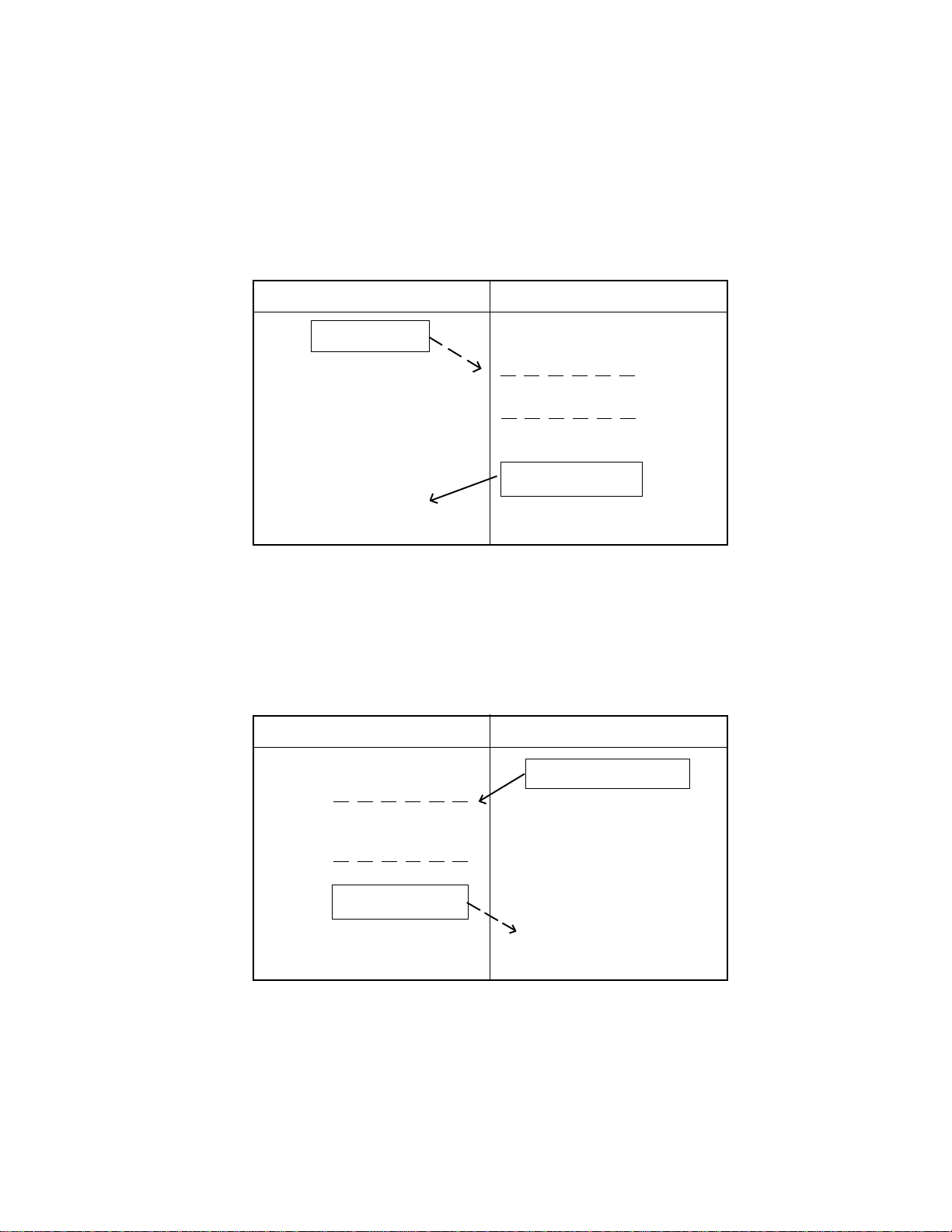
1.9 The Operational Flow Chart
There will be three kinds of communication flow between the RE-350 and the PC as follows:
Flow Pattern 1: Command Communication Flow Pattern
This flow will be applied when the PC sends a command to the RE-350 to request an operation.
PC
Command
The RE-350 is under operation.
Flow Pattern 2: Event Packet Flow Pattern
This flow will be applied when the RE-350 sends an “Event Data Packet” to the PC to tell that the {RS-232}
button on the operation panel was pressed.
PC
RE-350
C-response
RE-350
The PC is under
operation for this data.
E-response
Event Data Packet
17
Page 18
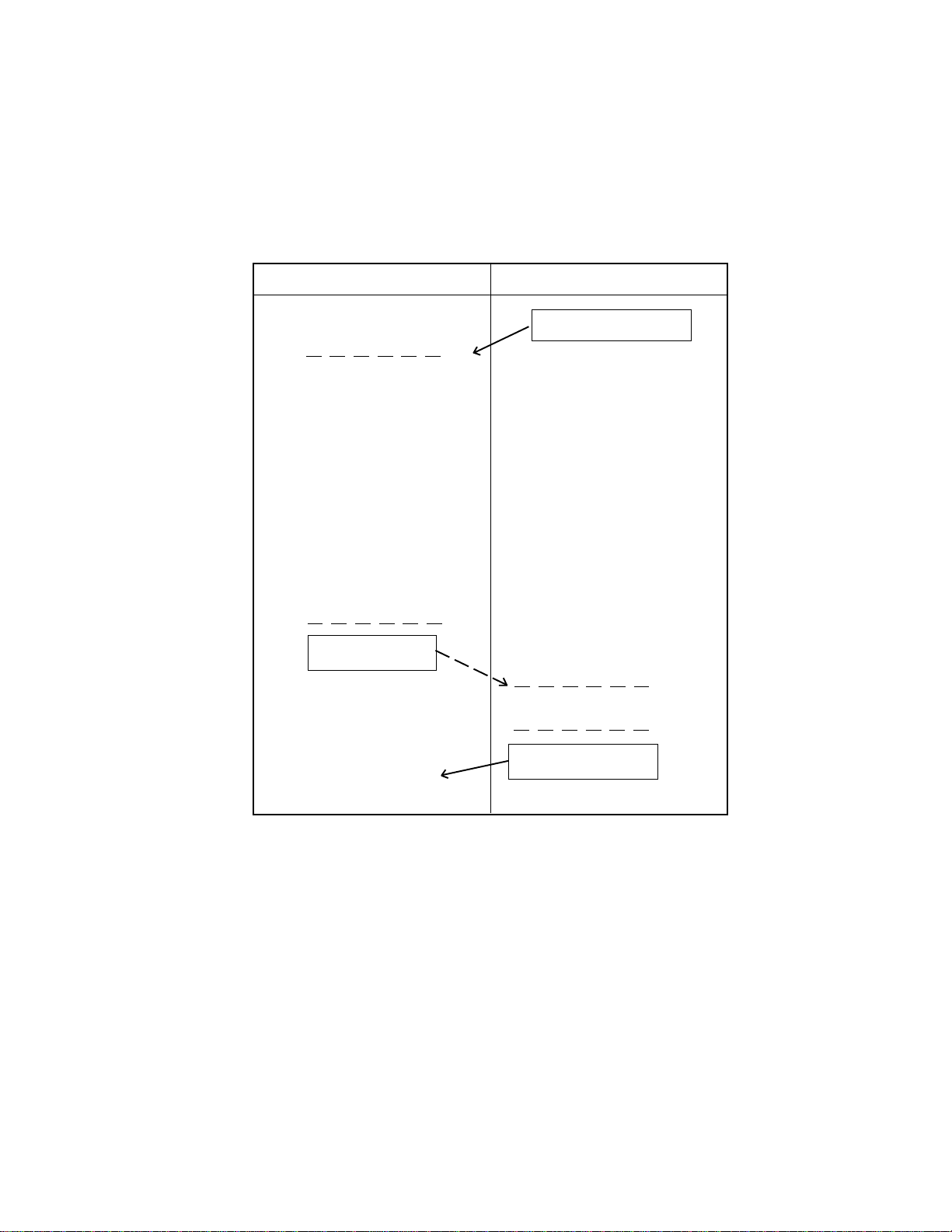
Flow Pattern 3: [N
This flow is applied when the RE-350 is in [N
buttons and control knobs on the front panel of the RE-350.
OTIFICATION
] Mode Flow Pattern
OTIFICATION
] Mode to tell the PC the condition of the
PC
The PC will compare the
current
previous
nize which button's or
control knob's status has
changed. If there is any
difference, the PC sends a
command to the RE-350 to
request the operation
defined by the difference in
FP data value.
FP data with the
FP data to recog-
Command
RE-350
FP Data Packet
RE-350 is under operation
C-response data
18
Page 19

2.0 Control Command and Packet Tables
2.1 Camera Control Commands Table
Maximum
#
Zoom
1 Cons-Spd wide Zoom High speed Wide zoom 500 $10 $8* $00 $01 $00
2 Step wide Zooming Step feed wide zooming 2000 $10 $8* $00 $03 $00
3 Cons-Spd Tele Zoom High speed Tele zoom 500 $10 $8* $01 $01 $00
4 Step Tele Zooming Step feed tele zooming 2000 $10 $8* $01 $03 $00
5 Stop Zooming Stop zooming motor 500 $10 $8* $02 $00 $00
6 Access-to-Zoom Access to a Zoom Position 9000 $10 $8* $03 $00 $**
7 Request Zoom Request Zoom position 100 $10 $8* $04 $00 $00
8 Wide Zoom w/ AF
9 Tele Zoom w/ AF
Focus
10 OP AF Operate auto focus 20000 $10 $8* $10 $00 $00
11 Cons-Spd focus near High speed focus near 500 $10 $8* $12 $01 $00
12 Step focus near Step feed focus near 2000 $10 $8* $12 $03 $00
13 Cons-Spd focus far High speed focus far 500 $10 $8* $13 $01 $00
Name
†
†
Description
High spd Wide zoom w/AF 500 $10 $8* $05 $00 $00
High spd Tele zoom w/AF 500 $10 $8* $06 $00 $00
operation
time(ms)
1 byte
Header
2 byte
ID number
3 byte
Command
4 byte
Param(H)
5 byte
Param(L)
14 Step focus far Step feed focus far 2000 $10 $8* $13 $03 $00
15 Stop focusing Stop the auto focus 500 $10 $8* $14 $00 $00
Color
16 OP A WB Operate Auto White Bal. 7000 $10 $8* $20 $00 $00
17 Access to WB Access to a WB position 500 $10 $8* $22 $00 $**
18 Access to EXP Access to a EXP position 500 $10 $8* $2A $00 $**
19 Access to Detail Access to a Detail position 500 $10 $8* $30 $00 $**
20 Set Positive mode
21 Set Negative mode ††Set negative image mode 500 $10 $8* $38 $01 $00
22 Set Color mode Set Color output mode 500 $10 $8* $40 $00 $00
23 Set B/W mode Set B/W output mode 500 $10 $8* $40 $01 $00
†
The RE-350 responds with a C-response data packet immediately after the reception of this command, but it is
still working on the Zoom control and AF adjustment.
††
The RE-350 responds with a C-response data packet immediately after the reception of this command, but it is
still working on the AWB adjustment.
††
Set positive image mode 500 $10 $8* $38 $00 $00
19
Page 20

2.2 System Control Commands Table
Maximum
#
Name
Description
operation
time(ms)
1 byte
Header
2 byte
ID number
3 byte
Command
4 byte
Param(H)
5 byte
Param(L)
Select Input Signal
1 Select Document Video Output Camera signal 500 $10 $8* $50 $00 $00
2 Select External video Output External signal 500 $10 $8* $50 $01 $00
Light on/off Control
3 Lights On
4 Lights Off
5 Backlight On
6 Backlight Off
††
††
††
††
Turn Light On 500 $10 $8* $58 $00 $00
Turn Light Off 500 $10 $8* $58 $01 $00
Turn Backlight On 500 $10 $8* $59 $00 $00
Turn Backlight Off 500 $10 $8* $59 $01 $00
LED
7 LED Normal Set LED Condition Normal 500 $10 $8* $68 $** $00
8 LED On Turn LED On 500 $10 $8* $69 $** $00
9 LED Off Turn LED Off 500 $10 $8* $6A $** $00
10 LED Blink Blink LED 500 $10 $8* $6B $** $00
Communication Control
11 OFF Line Set to [OFF LINE] Mode 500 $10 $8* $70 $00 $00
12 ON Line Set to [ON LINE] Mode 500 $10 $8* $70 $01 $00
13 Notification Set to [Notification] Mode 500 $10 $8* $70 $02 $00
Status Request
14 Status of Group A Request Status Group A 100 $10 $8* $80 $00 $00
15 Status of Group B Request Status Group B 100 $10 $8* $80 $01 $00
16 Status of Button Request Button condition 100 $10 $8* $81 $00 $00
17 Status of WB Control Request WB vol. position 100 $10 $8* $82 $00 $00
18 Status of EXP Control Request EXP vol. position 100 $10 $8* $82 $01 $00
19 Status of Detail Vol. Request Detail vol. position 100 $10 $8* $82 $02 $00
20 Status of AWB Result Request AWB result data 100 $10 $8* $83 $00 $00
21 Name of Equipment Request Name of equip. 100 $10 $8* $88 $00 $00
22 Version of ROM Request ROM version 100 $10 $8* $88 $01 $00
Set to Special Mode
23 Set to Tempor ary Mode Set to temp. mode 100 $10 $8* $F0 $00 $00
24 Set to Service Mode Set to service mode 100 $10 $8* $F1 $FF $FF
25 Set to Data Read Out Set to data read mode 100 $10 $8* $F1 $FF $00
††
The RE-350 responds with a C-response data packet immediately after the reception of this command, but it is
still working on the AWB adjustment.
20
Page 21

2.3 C-response Data Packet Table
C-response Description 1 byte 2 byte 3 byte 4 byte 5 byte
Normal
Response
Header ID #
Response without parameter $A0 $8* $00 $00 $00
Read Zoom position $A0 $8* $10 $00 $**
Status of Group A $A0 $8* $20 $** $**
Status of Group B $A0 $8* $21 $** $00
Status of Button $A0 $8* $30 $** $**
Status of WB control knob $A0 $8* $40 $00 $**
Status of EXP control knob $A0 $8* $41 $00 $**
Status of Detail control knob $A0 $8* $42 $00 $**
Status of AWB result $A0 $8* $43 $00 $**
Name of the Equipment $A0 $8* $48 $** $**
Version of ROM $A0 $8* $49 $** $**
Response Para(H) Para(L)
System Error $A0 $8* $F0 $00 $00
Error
Mode Error $A0 $8* $F0 $00 $01
Response
Time out error $A0 $8* $F0 $00 $02
System error response
If the RE-350 has a fatal error which it cannot recover from while performing a command from the PC, the RE-350
will send this response and stop the current operation.
Mode error response
Depending on the mode, [O
case, the Mode error response will be sent to the PC.
For Example: If the RE-350 is in the [OFF-L
give a Mode error response because in this mode such a command cannot be executed.
N-LINE
] or [OFF-L
INE
INE
], the RE-350 may not be able to execute some commands. In this
] Mode and the <Zoom Wide> command is issued, the RE-350 will
Time out error response
When the RE-350 is given the command <OP AF> or <OP AWB> from the PC and it tries to perform the command
but cannot finish the operation successfully in an expected period, this error is given.
21
Page 22

2.4 Event Data Packet Table
Event Description 1 byte 2 byte 3 byte 4 byte 5 byte
Header ID # EVENT# Para(H) Para(L)
Request ON Line $20 $8* $00 $00 $00
Request OFF Line $20 $8* $00 $01 $00
Request ON line
When the {RS-232} button on the front panel is pushed and the RTS signal line from the PC is on, the RE-350 will
send this “Event Data Packet” to the PC. If the RE-350 can receive the <Accepted> of the “E-response Packet” in 1
second, the RE-350’s mode will switch to [O
packet” twice, the
RE-350 will stay in [O
Request OFF line
When the {RS-232} button on the front panel is pushed to try to set the RE-350 to [OFF-L
signal line from the PC is on, the RE-350 will send this “Event Data Packet” to the PC. If the RE-350 can receive the
<Accepted> of the “E-response packet”, the RE-350’s mode will shift to the [OFF-L
response from the PC, then the RE-350's mode changes to [OFF-L
N-LINE
FF-LINE
]. If not or no E-response after repeating the above “Event data
] mode.
INE
] Mode and the RTS
INE
] Mode. Also, if there is no
INE
].
22
Page 23

2.5 E-response Data Packet Table
E-response Description 1 byte 2 byte 3 byte 4 byte 5 byte
Header ID # EVENT# Para(H) Para(L)
Accepted $B0 $8* $00 $00 $00
Denied $B0 $8* $00 $01 $00
Accepted
When the PC receives an “Event Data Packet” (‘Request ON line’ or ‘Request OFF line’) from the RE-350, the PC
should send this E-response packet back to the RE-350 to tell that the PC can disconnect from or connect to the RE-
. After the RE-350 receives this request, it takes one second to complete.
350
Denied
When the PC receives an “Event Data Packet” (‘Request ON line’ or ‘Request OFF line’) from the RE-350, and the PC
cannot accept this request, the PC should send this response packet to the RE-350. After the RE-350 receives this
request, it takes one second to complete.
23
Page 24

2.6 FP Data Packet Table
FP data description 1 byte 2 byte 3 byte 4 byte 5 byte
Header ID # EVENT# Para(H) Para(L)
Front panel switch information $30 $8* $00 $** $**
FP Data Packet
When the RE-350 is in [N
each button and control knob every time the condition varies.
The bit assignment of the parameter is as follows:
D15 D14 D13 D12 D11 D10 D9 D8
W/B Vol 0 Focus Auto B/W W/B Auto Nega Inputselect 0
D7 D6 D5 D4 D3 D2 D1 D0
Detail Vol EXP Vol Back light Lights Zoom Tele Zoom Wide Focus Far Focus Near
OTIFICATION
] Mode, it will send the “FP Data Packet” to the PC. This tells the condition of
If a control knob has not been used for longer than 500 milliseconds, the RE-350 will send the “FP-Data Packet” with
the corresponding control knob bit cleared.
Note: If the RTS signal line of the PC is off and the RE-350 is in [N
the “FP-Data Packet” which explains the button and control knob condition at the time when the RTS signal
line comes on.
OTIFICATION
] Mode, the RE-350 will start to send
24
Page 25

3.0 Description Command Data Packet
3.1 Zoom Commands
Wide Zoom: Constant Speed
• Function:
Moves the zoom lens in the wider direction at a constant speed. This operation will be stopped with the reception
of the <Stop Zooming> command or if the zoom lens reaches the wide-end limit.
• Timing of the “C-response Packet” sent to the PC:
Right after the zoom lens start to move.
• The parameter of the “C-response Packet”:
$0000 fixed
• The maximum operation time (msec):
500 millisecond
• Command format:
Header ID number Command Parameter MSH Parameter LSH
$10 $ 8 * $ 0 0 $ 0 1 $ 0 0
Note: The speed of the zooming will be constant from the beginning to the end of this operation. This is different
from when the {ZOOM WIDE} button on the front panel is pushed. If the {ZOOM WIDE} button is pushed
and continues to be pushed for longer than one second, the zooming will increase to a faster speed.
Wide Zoom: Step
• Function:
Moves the zoom lens in the wider direction one step. This operation will be stopped
automatically after the zoom lens has stopped.
• Timing of the “C-response packet” sent to the PC:
Right after the zoom lens stops.
• The parameter of the “C-response packet”:
$0000 fixed
• The maximum operation time (msec):
2000 millisecond
• Command format:
Header ID number Command Parameter MSH Parameter LSH
$10 $ 8 * $ 0 0 $ 0 3 $ 0 0
25
Page 26

Tele Zoom: Constant Speed
• Function:
Moves the zoom lens in the tele direction at a constant speed. This operation will be stopped with the reception of
the <Stop Zooming> command or the zoom lens reaches the tele-end limit.
• Timing of the “C-response Packet” sent to the PC:
Right after the zoom lens start to move.
• The parameter of the “C-response Packet”:
$0000 fixed
• The maximum operation time (msec):
500 millisecond
• Command format:
Header ID number Command Parameter MSH Parameter LSH
$10 $ 8 * $ 0 1 $ 0 1 $ 0 0
Note: The speed of the zooming will be constant from the beginning to the end of this operation. This is different
from when the {ZOOM TELE} button on the panel is pushed. If the {ZOOM TELE} button is pushed and
continues to be pushed for longer than one second, the zooming will increase to a faster speed.
Tele Zoom: Step
• Function:
Moves the zoom lens in the tele direction one step. This operation will be stopped automatically after the zoom
lens has stepped.
• Timing of the “C-response Packet” sent to the PC:
Right after the zoom lens stops.
• The parameter of the “C-response Packet”:
$0000 fixed
• The maximum operation time (msec):
2000 millisecond
• Command format:
Header ID number Command Parameter MSH Parameter LSH
$10 $ 8 * $ 0 1 $ 0 3 $ 0 0
26
Page 27

Zoom: Stop
• Function:
Stops the movement of the zooming lens.
• Timing of the “C-response Packet” sent to the PC:
Right after the zoom lens stops to move.
• The parameter of the “C-response Packet”:
$0000 fixed
• The maximum operation time (msec):
500 millisecond
• Command format:
Header ID number Command Parameter MSH Parameter LSH
$10 $ 8 * $ 0 2 $ 0 0 $ 0 0
Zoom: Access To Position
• Function:
Moves the zoom lens to a designated position determined by the parameter in this command packet.
• The available parameter value:
LSH: $00 ~ $FF
• Timing of the “C-response Packet” sent to the PC:
Right after the zoom lens reaches the designated position.
• The parameter of the “C-response Packet”:
$0000 fixed
• The maximum operation time (msec):
9000 millisecond
• Command format:
Header ID number Command Parameter MSH Parameter LSH
$10 $ 8 * $ 0 3 $ 0 0 $ * *
27
Page 28

Zoom: Request Position
• Function:
Requests the present position of the zoom lens from the RE-350.
• Timing of the “C-response Packet” sent to the PC:
Right after this command is accepted by the RE-350.
• The parameter of the “C-response Packet”:
The present zoom lens position data:
MSH:$00 fixed LSH:$00 ~ $FF
• The maximum operation time (msec):
100 millisecond
• Command format:
Header ID number Command Parameter MSH Parameter LSH
$10 $ 8 * $ 0 4 $ 0 0 $ 0 0
28
Page 29

Zoom Wide: Constant Speed w/ AF
• Function:
Moves the zoom lens in the wider direction at a constant speed. This operation will be stopped with the reception
of the <Stop Zooming> command or if the zoom lens reaches the wide-end limit.
• Timing of the “C-response Packet” sent to the PC:
Right after the zoom lens start to move.
• The parameter of the “C-response Packet”:
$0000 fixed
• The maximum operation time (msec):
500 millisecond
• Command format:
Header ID number Command Parameter MSH Parameter LSH
†
$10 $ 8 * $ 0 5 $ 0 0 $ 0 0
Zoom Tele: Constant Speed w/ AF
• Function:
Moves the zoom lens in the tele direction at a constant speed. This operation will be stopped with the reception of
the <Stop Zooming> command or the zoom lens reaches the tele-end limit.
• Timing of the “C-response Packet” sent to the PC:
Right after the zoom lens start to move.
• The parameter of the “C-response Packet”:
$0000 fixed
• The maximum operation time (msec):
500 millisecond
• Command format:
Header ID number Command Parameter MSH Parameter LSH
†
$10 $ 8 * $ 0 6 $ 0 0 $ 0 0
†
The speed of the zooming will be constant from the beginning to the end of this operation. This is different from
when the {ZOOM WIDE} or {ZOOM TELE} button on the front panel is pushed. If the {ZOOM WIDE} or {ZOOM
} button is pushed and continues to be pushed for longer than one second, the zooming will increase to a
TELE
faster speed.
The RE-350 responds with a C-response data packet immediately after the reception of this command, but it is still
working on the Zoom control and AF adjustment.
29
Page 30

3.2 Focus Commands
OP AF (Operate Auto Focus)
• Function:
Perform AF once, finding out the best focused position.
• Timing of the “C-response Packet” sent to the PC:
Right after having found out the best focal point or, after a 6 second trial, having failed to find the best focal point.
• The parameter of the “C-response Packet”:
$0000 fixed
• The maximum operation time (msec):
20000 millisecond
• Command format:
Header ID number Command Parameter MSH Parameter LSH
$10 $ 8 * $ 1 0 $ 0 0 $ 0 0
Focus Near: Constant Speed
• Function:
Moves the focus lens in the near direction at a constant speed. This operation will be stopped with the reception of
the <Stop focusing> command or the focus lens reaches the near-end limit.
• Timing of the “C-response Packet” sent to the PC:
Right after the focus lens starts to move.
• The parameter of the “C-response Packet”:
$0000 fixed
• The maximum operation time (msec):
500 millisecond
• Command format:
Header ID number Command Parameter MSH Parameter LSH
$10 $ 8 * $1 2 $ 0 1 $ 0 0
30
Page 31

Focus Near: Step
• Function:
Moves the focus lens in the near direction one step.
This operation will be stopped automatically.
• Timing of the “C-response Packet” sent to the PC:
Right after the focus lens stops.
• The parameter of the “C-response Packet”:
$0000 fixed
• The maximum operation time (msec):
2000 millisecond
• Command format:
Header ID number Command Parameter MSH Parameter LSH
$10 $ 8 * $ 1 2 $ 0 3 $ 0 0
Focus Far: Constant Speed
• Function:
Moves the focus lens in the far direction at a constant speed. This operation will be stopped with the reception of
the <Stop focusing> command or the focus lens reaches the far-end limit.
• Timing of the “C-response Packet” sent to the PC:
Right after the focus lens starts to move.
• The parameter of the “C-response Packet”:
$0000 fixed
• The maximum operation time (msec):
500 millisecond
• Command format:
Header ID number Command Parameter MSH Parameter LSH
$10 $ 8 * $1 3 $ 0 1 $ 0 0
31
Page 32

Focus Far: Step
• Function:
Moves the focus lens in the far direction one step. This operation stops automatically.
• Timing of the “C-response Packet” sent to the PC:
Right after the focus lens stops
• The parameter of the “C-response Packet”:
$0000 fixed
• The maximum operation time (msec):
2000 millisecond
• Command format:
Header ID number Command Parameter MSH Parameter LSH
$10 $ 8 * $ 1 3 $ 0 3 $ 0 0
Focus: Stop
• Function:
Stops the focusing motor that moves the focus lens.
• Timing of the “C-response Packet” sent to the PC:
Right after the focus lens stops.
• The parameter of the “C-response Packet”:
$0000 fixed
• The maximum operation time (msec):
500 millisecond
• Command format:
Header ID number Command Parameter MSH Parameter LSH
$10 $ 8 * $1 4 $ 0 0 $ 0 0
32
Page 33

3.3 White Balance Commands
OP AWB (Operate Auto-White Balance)
• Function:
Instructs the auto white balance to find the best white balance.
• Timing of the “C-response Packet” sent to the PC:
Right after having found out the best white balance point or, after 6 seconds, having failed to find a proper
• The parameter of the “C-response Packet”:
$0000 fixed
• The maximum operation time (msec):
7000 millisecond
• Command format:
Header ID number Command Parameter MSH Parameter LSH
$10 $ 8 * $ 2 0 $ 0 0 $ 0 0
WB.
White Balance: Manual Access To
• Function:
Sets a designated white balance position, which is determined by the parameter of this command, based on the Auto
White Balance value as returned by the <Status of AWB Result> command (p.51). The AWB value should be known
so the adjustment can be made properly, in the correct direction. This command is similar to rotating the manual
control knob on the front panel. Note: The control knob’s physical position is not updated by this command.
• Available parameter value:
LSH: $ 00 ~ $ FF
• Timing of the “C-response Packet” sent to the PC:
Right after the compensation of WB is performed.
• The parameter of the “C-response Packet”:
$0000 fixed
• The maximum operation time (msec):
500 millisecond
• Command format:
Header ID number Command Parameter MSH Parameter LSH
$10 $ 8 * $2 2 $ 0 0 $ * *
33
Page 34

3.4 Exposure Commands
Exposure: Manual Access To
• Function:
Sets a designated exposure position, which is determined by the parameter of this command. The result is the same
as rotating the manual control knob on the front panel.
Note:
The control knob’s physical position is not updated by this command.
This command simply modifies the target exposure default value which is $80.
• Available parameter value:
LSH: $ 00 (darker)~ $ FF (brighter)
• Timing of the “C-response Packet” sent to the PC:
Right after the Manual Exposure command is performed.
• The parameter of the “C-response Packet”:
$0000 fixed
• The maximum operation time (msec):
500 millisecond
• Command format:
Header ID number Command Parameter MSH Parameter LSH
$10 $ 8 * $ 2A $ 0 0 $* *
34
Page 35

3.5 Detail Commands
Detail: Manual Access To
• Function:
Sets a designated sharpness position, which is determined by the parameter of this command. The result is the same
as rotating the manual control knob on the front panel.
Note:
The control knob’s physical position is not updated by this command.
This command simply modifies the target exposure default value which is $80.
• Available parameter value:
LSH: $ 00 (less detail)~ $ FF (more detail)
• Timing of the “C-response Packet” sent to the PC:
Right after the sharpness is adjusted.
• The parameter of the “C-response Packet”:
$0000 fixed
• The maximum operation time (msec):
500 millisecond
• Command format:
Header ID number Command Parameter MSH Parameter LSH
$10 $ 8 * $3 0 $ 0 0 $ * *
35
Page 36

3.6 Positive/Negative Commands
Set Positive Mode
• Function:
Sets the video output to normal (positive). (Also, the Auto-White Balance will be adjusted once.)
• Timing of the “C-response Packet” sent to the PC:
Right after this setting is done.
• The parameter of the “C-response Packet”:
$0000 fixed
• The maximum operation time (msec):
500 millisecond
• Command format:
Header ID number Command Parameter MSH Parameter LSH
†
$10 $ 8 * $ 3 8 $ 0 0 $ 0 0
Set Negative Mode
• Function:
Sets the video output to negative. (Also, the Auto-White Balance will be adjusted once.)
• Timing of the “C-response Packet” sent to the PC:
Right after this setting is done.
• The parameter of the “C-response Packet”:
$0000 fixed
• The maximum operation time (msec):
500 millisecond
• Command format:
Header ID number Command Parameter MSH Parameter LSH
†
$10 $ 8 * $ 38 $ 0 1 $ 0 0
†
The RE-350 responds in 500 msec with a C-response data packet after the reception of this command, but it will
be still working on the AWB adjustment. (The real AWB operation time will be longer than 500 msec.)
36
Page 37

3.7 Color/B&W Commands
Set Color Mode
• Function:
Sets the video output to color.
• Timing of the “C-response Packet” sent to the PC:
Right after this setting is done.
• The parameter of the “C-response Packet”:
$0000 fixed
• The maximum operation time (msec):
500 millisecond
• Command format:
Header ID number Command Parameter MSH Parameter LSH
$10 $ 8 * $ 4 0 $ 0 0 $ 0 0
Set B/W Mode
• Function:
Sets the video output to black & white.
• Timing of the “C-response Packet” sent to the PC:
Right after this setting is done.
• The parameter of the “C-response Packet”:
$0000 fixed
• The maximum operation time (msec):
500 millisecond
• Command format:
Header ID number Command Parameter MSH Parameter LSH
$10 $ 8 * $ 4 0 $ 0 1 $ 0 0
37
Page 38

4.0 System Control Commands
4.1 Detailed System Control Commands
Select Document Video
• Function:
Selects the Document camera video.
• Timing of the “C-response Packet” sent to the PC:
Right after this setting is done.
• The parameter of the “C-response Packet”:
$0000 fixed
• The maximum operation time (msec):
500 millisecond
• Command format:
Header ID number Command Parameter MSH Parameter LSH
$10 $ 8 * $ 5 0 $ 0 0 $ 0 0
Select External Video
• Function:
Selects the external video input signal.
• Timing of the “C-response Packet” sent to the PC:
Right after this setting is done.
• The parameter of the “C-response Packet”:
$0000 fixed
• The maximum operation time (msec):
500 millisecond
• Command format:
Header ID number Command Parameter MSH Parameter LSH
$10 $ 8 * $5 0 $ 0 1 $ 0 0
38
Page 39

Document Lights: On
†
• Function:
Turns on the document lights above the document table. (Also, the Auto-White Balance will be adjusted once.)
Note: If the Backlight is already on, and the Document Lights are turned on, then the Backlight will be turned off
automatically and only the Document Lights will remain on.
• Timing of the “C-response Packet” sent to the PC:
Right after turning on the lights.
• The parameter of the “C-response Packet”:
$0000 fixed
• The maximum operation time (msec):
500 millisecond
• Command format:
Header ID number Command Parameter MSH Parameter LSH
$10 $ 8 * $ 5 8 $ 0 0 $ 0 0
Document Lights: Off
• Function:
Turns off the Document Lights above the document table. (Also, the Auto-White Balance will be adjusted once.)
• Timing of the “C-response Packet” sent to the PC:
Right after turning off the lights.
• The parameter of the “C-response Packet”:
$0000 fixed
• The maximum operation time (msec):
500 millisecond
• Command format:
Header ID number Command Parameter MSH Parameter LSH
†
$10 $ 8 * $5 8 $ 0 1 $ 0 0
†
The RE-350 responds in 500 msec with a C-response data packet after the reception of this command, but it will
be still working on the AWB adjustment. (The real AWB operation time will be longer than 500 msec.)
39
Page 40

Backlight: On
†
• Function:
Turns on the Backlight under the document table. (Also, the Auto-White Balance will be adjusted once.)
Note: If the Document Lights are already on, and the Backlight is turned on, then the Document Lights will be
turned off automatically and only the backlight will remain on.
• Timing of the “C-response Packet” sent to the PC:
Right after turning on the backlight.
• The parameter of the “C-response Packet”:
$0000 fixed
• The maximum operation time (msec):
500 millisecond
• Command format:
Header ID number Command Parameter MSH Parameter LSH
$10 $ 8 * $ 5 9 $ 0 $ 0 0
Backlight: Off
• Function:
Turns off the document lights above the document table. (Also, the Auto-White Balance will be adjusted once.)
• Timing of the “C-response Packet” sent to the PC:
Right after turning off the backlight.
• The parameter of the “C-response Packet”:
$0000 fixed
• The maximum operation time (msec):
500 millisecond
• Command format:
Header ID number Command Parameter MSH Parameter LSH
†
$10 $ 8 * $5 9 $ 0 1 $ 0 0
†
The RE-350 responds in 500 msec with a C-response data packet after the reception of this command, but it will
be still working on the AWB adjustment. (The real AWB operation time will be longer than 500 msec.)
40
Page 41

LED: Normal
• Function:
The LED indicated by the parameter data will be set to normal operation. This command is available in the
[N
OTIFICATION
“C-response Packet” with the Mode Error response.
• The available parameter value:
LSH: $00 ~ $FF
• Timing of the “C-response Packet” sent to the PC:
Right after this setting is done.
• The parameter of the “C-response Packet”:
$0000 fixed
• The maximum operation time (msec):
500 millisecond
• Command format:
] Mode. If the RE-350 receives this command from the PC in another mode, the RE-350 will send a
Header ID number Command Parameter MSH Parameter LSH
$10 $ 8 * $ 6 8 $ * * $ 0 0
• The bit assignment for the parameter data:
Each bit corresponds to each LED on the operation panel.
D15 D14 D13 D12 D11 D10 D9 D8
RS-232 Input select NEGA WB Auto B/W Focus Auto Lights Backlight
41
Page 42

LED: On
• Function:
The LED indicated by the parameter data will be turned on. This command is available in the [N
If the RE-350 receives this command from the PC in another mode, the RE-350 will send a “C-response Packet”
with the Mode Error response.
• The available parameter value:
LSH: $00 ~ $FF
• Timing of the “C-response Packet” sent to the PC:
Right after this setting is done.
• The parameter of the “C-response Packet”:
$0000 fixed
• The maximum operation time (msec):
500 millisecond
• Command format:
OTIFICATION
] Mode.
Header ID number Command Parameter MSH Parameter LSH
$10 $ 8 * $ 6 9 $ * * $ 0 0
• The bit assignment for the parameter data:
Each bit corresponds to each LED on the operation panel.
D15 D14 D13 D12 D11 D10 D9 D8
RS-232 Input select NEGA WB Auto B/W Focus Auto Lights Backlight
42
Page 43

LED: Off
• Function:
The LED indicated by the parameter data will be turned off. This command is available in the [N
If the RE-350 receives this command from the PC in another mode, the RE-350 will send a “C-response Packet”
with the Mode Error response.
• The available parameter value:
LSH: $00 ~ $FF
• Timing of the “C-response packet” sent to the PC:
Right after this setting is done.
• The parameter of the “C-response packet”:
$0000 fixed
• The maximum operation time (msec):
500 millisecond
• Command format:
OTIFICATION
] Mode.
Header ID number Command Parameter MSH Parameter LSH
$10 $ 8 * $ 6 A $ * * $ 0 0
• The bit assignment for the parameter data:
Each bit corresponds to each LED on the operation panel.
D15 D14 D13 D12 D11 D10 D9 D8
RS-232 Input select NEGA W/B Auto B/W Focus Auto Lights Backlight
43
Page 44

LED: Blink
• Function:
The LED indicated by the parameter data will be made to blink. This command is available in the [N
Mode. If the RE-350 receives this command from the PC in another mode, the RE-350 will send a “C-response
Packet” with the Mode Error response.
• The available parameter value:
LSH: $00 ~ $FF
• Timing of the “C-response Packet” sent to the PC:
Right after this setting is done.
• The parameter of the “C-response Packet”:
$0000 fixed
• The maximum operation time (msec):
500 millisecond
• Command format:
OTIFICATION
]
Header ID number Command Parameter MSH Parameter LSH
$10 $ 8 * $ 6 B $ * * $ 0 0
• The bit assignment for the parameter data:
Each bit corresponds to each LED on the operation panel.
D15 D14 D13 D12 D11 D10 D9 D8
RS-232 Input select NEGA W/B Auto B/W Focus Auto Lights Backlight
44
Page 45

[OFF-L
• Function:
• Timing of the “C-response Packet” sent to the PC:
• The parameter of the “C-response Packet”:
• The maximum operation time (msec):
• Command format:
INE
] Mode
Sets the RE-350 to [OFF-L
Right after this setting is done.
$0000 fixed
500 millisecond
Header ID number Command Parameter MSH Parameter LSH
INE
] Mode.
$10 $ 8 * $ 7 0 $ 0 0 $ 0 0
[ON-L
• Function:
• Timing of the “C-response Packet” sent to the PC:
• The parameter of the “C-response Packet”:
• The maximum operation time (msec):
• Command format:
INE
] Mode
Sets the RE-350 to [ON-L
Right after this setting is done.
$0000 fixed
500 millisecond
Header ID number Command Parameter MSH Parameter LSH
INE
] Mode.
$10 $ 8 * $ 7 0 $ 0 1 $ 0 0
45
Page 46

[N
OTIFICATION
• Function:
Sets the RE-350 to [N
• Timing of the “C-response Packet” sent to the PC:
Right after this setting is done.
• The parameter of the “C-response Packet”:
$0000 fixed
• The maximum operation time (msec):
500 millisecond
• Command format:
Header ID number Command Parameter MSH Parameter LSH
] Mode
OTIFICATION
] Mode.
$10 $ 8 * $ 7 0 $ 0 2 $ 0 0
46
Page 47

Status of Group A
• Function:
To get the status data of Group A from the RE-350 .
• Timing of the “C-response Packet” sent to the PC:
Right after this command is received by the
• The parameter of the “C-response Packet”:
The bit assignment to each status to explain the
D15 D14 D13 D12 D11 D10 D9 D8
On-zoom On-zoom At-zoom At-zoom On-focus On-focus At-focus At-focus
Wide Tele Wide-end Tele-end Far Near Far-end Near-end
D7 D6 D5 D4 D3 D2 D1 D0
0 0 AF good/NG AWB good/NG 0 VideoP/N VideoC/M 0
Note:
Good ---> 1 NG ---> 0
P (posi) ---> 1 N(nega) ---> 0
C(color) ---> 1 M(mono) ---> 0
On-zoom: actively zooming, At-zoom: Arrived at the maximum zoom position.
On-focus: actively focusing, At-focus: Arrived at the maximum focal position.
RE-350.
RE-350’s condition.
• The maximum operation time (msec):
100 millisecond
• Command format:
Header ID number Command Parameter MSH Parameter LSH
$10 $ 8 * $ 8 0 $ 0 0 $ 0 0
47
Page 48

Status of Group B
• Function:
To get the status data of Group B from the RE-350 .
• Timing of the “C-response Packet” sent to the PC:
Right after this command is received by the
RE-350.
• The parameter of the “C-response Packet”:
The bit assignment to each status to explain the
RE-350’s condition.
D15 D14 D13 D12 D11 D10 D9 D8
Input Lights Backlight C MODE C MODE 0 0 0
Camera/Ext ON/OFF ON/OFF 1 0
D7 D6 D5 D4 D3 D2 D1 D0
0 0 0 0 0 0 0 0
Note:
1 = ON 0 = OFF
C MODE 1 and C MODE 0 explain the operational mode of the RE-350 as follows:
MODE C MODE 1 C MODE 0
OFF-L
INE
ON-L
INE
N
OTIFICATION
– –– –
01
10
not used 1 1
• The maximum operation time (msec):
100 millisecond
• Command format:
Header ID number Command Parameter MSH Parameter LSH
$10 $ 8 * $ 8 0 $ 0 1 $ 0 0
48
Page 49

Status of the Buttons
• Function:
To get the status of the buttons on the operation panel .
• Timing of the “C-response Packet” sent to the PC:
Right after this command is received by the
• The parameter of the “C-response Packet”:
The bit assignment to each status to explain the RE-350’s condition.
D15 D14 D13 D12 D11 D10 D9 D8
RE-350.
0 0 Focus B/W W/B NEGA Input RS-232
Auto Select Control
D7 D6 D5 D4 D3 D2 D1 D0
0 0 Backlight Lights Zoom Zoom Focus Focus
• The maximum operation time (msec):
100 millisecond
• Command format:
Header ID number Command Parameter MSH Parameter LSH
TELE WIDE FAR NEAR
$10 $ 8 * $ 8 1 $ 0 0 $ 0 0
49
Page 50

Status of WB control knob
• Function:
Gets the position data of the White Balance Manual control knob.
• Timing of the “C-response Packet” sent to the PC:
Right after this command is received by the
• The parameter of the “C-response Packet”:
MSH: $00 fixed LSH: $00 ~ $FF
• The maximum operation time (msec):
100 millisecond
• Command format:
Header ID number Command Parameter MSH Parameter LSH
RE-350.
$10 $ 8 * $ 82 $ 0 0 $ 0 0
Status of EXP control knob
• Function:
Gets the position data of the EXP control knob. (EXP = exposure)
• Timing of the “C-response Packet” sent to the PC:
Right after this command is received by the RE-350.
• The parameter of the “C-response Packet”:
MSH: $00 fixed LSH: $00 ~ $FF
• The maximum operation time (msec):
100 millisecond
• Command format:
Header ID number Command Parameter MSH Parameter LSH
$10 $ 8 * $ 82 $ 0 1 $ 0 0
50
Page 51

Status of Detail control knob
• Function:
Gets the position data of the Detail control knob.
• Timing of the “C-response Packet” sent to the PC:
Right after this command is received by the
• The parameter of the “C-response Packet”:
MSH: $00 fixed LSH: $00 ~ $FF
• The maximum operation time (msec):
100 millisecond
• Command format:
Header ID number Command Parameter MSH Parameter LSH
RE-350.
$10 $ 8 * $ 8 2 $ 0 2 $ 0 0
Status of AWB result
• Function:
Gets the position data of the White Balance Manual control knob where Auto-White Balance is completed.
• Timing of the “C-response Packet” sent to the PC:
Right after this command is received by the RE-350.
• The parameter of the “C-response Packet”:
MSH: $00 fixed LSH: $00 ~ $FF
• The maximum operation time (msec):
100 millisecond
• Command format:
Header ID number Command Parameter MSH Parameter LSH
$10 $ 8 * $ 8 3 $ 0 0 $ 0 0
51
Page 52

Name of the Equipment
• Function:
Gets the code name of the equipment which is connected to the PC.
The code name of the RE-350 is “R1”.
• Timing of the “C-response Packet” sent to the PC:
Right after this command is received by the RE-350.
• The parameter of the “C-response Packet”:
MSH:fixed LSH: fixed
The code name of the RE-350 is “R1”.
• The maximum operation time (msec):
100 millisecond
• Command format:
Header ID number Command Parameter MSH Parameter LSH
$10 $ 8 * $ 8 8 $ 0 0 $ 0 0
Version of ROM
• Function:
Gets the coded version number from each of the RE-350’s ROM's.
• Timing of the “C-response Packet” sent to the PC:
Right after this command is received by the RE-350.
• The parameter of the “C-response Packet”:
MSH: $XX LSH: $XX
The MSH parameter is the ROM version of the RE-350's camera head CPU.
The LSH parameter is the ROM version of the RE-350's main body CPU.
The above parameters (in ASCII Code) are variable and are set by the firmware.
• The maximum operation time (msec):
100 millisecond
• Command format:
Header ID number Command Parameter MSH Parameter LSH
$10 $ 8 * $ 8 8 $ 0 1 $ 0 0
52
Page 53

Set to Special Mode 1
• Function:
Lets the RE-350 transfer to Special Mode 1. The RE-350 will accept this command independently from its ID
number.
• Timing of the “C-response Packet” sent to the PC:
Right after this command is received by the RE-350.
• The parameter of the “C-response Packet”:
MSH: $00 fixed LSH: $00 fixed
• The maximum operation time (msec):
100 millisecond
• Command format:
Header ID number Command Parameter MSH Parameter LSH
$10 $ 8 * $F 0 $ 0 0 $ 0 0
Note: This command is prepared for service purposes ONLY and it is not
intended for use by the end-user.
Set to Special Mode 2
• Function:
Lets the RE-350 transfer to Special Mode 2. The RE-350 will accept this command independently from its ID
number.
• Timing of the “C-response Packet” sent to the PC:
Right after this command is received by the RE-350.
• The parameter of the “C-response Packet”:
MSH: $00 fixed LSH: $00 fixed
• The maximum operation time (msec):
100 millisecond
• Command format:
Header ID number Command Parameter MSH Parameter LSH
$10 $ 8 * $F 1 $F F $ 0 0
Note: This command is prepared for service purposes ONLY and it is not
intended for use by the end-user.
53
Page 54

Set to Service Mode
• Function:
Lets the RE-350 transfer to Service Mode. The RE-350 will accept this command independently from its ID
number.
• Timing of the “C-response Packet” sent to the PC:
Right after this command is received by the RE-350.
• The parameter of the “C-response Packet”:
MSH: $00 fixed LSH: $00 fixed
• The maximum operation time (msec):
100 millisecond
• Command format:
Header ID number Command Parameter MSH Parameter LSH
$10 $ 8 * $F 1 $F F $ F F
Note: This command is prepared for service purposes ONLY and it is not
intended for use by the end-user.
54
Page 55

5.0 Control Cable Pin Assignments
5.1 RS-232C Control Cable Pin Assignment
RE-350
RE-350
55
Page 56

RE-350 Control Cable Pin Assignments
9 Pin DSUB RS-232C
RE-350
RE-350
56
Page 57

RE-350 Control Cable Pin Assignments
RS-232C for Macintosh™ Computers
Note: RS-232C Specification allows cable length up to 15m, but it should be kept as
short as possible.
The following cables which have the above connections can be used:
Apple System Peripheral 8 1.0m
InMac 74415 (for Image Writer II) 1.8m
57
Page 58

6.0 Timing Charts
6.1 RTS/CTS Flow Control Timing Chart
PC SIDE SIGNAL
RTS
CTS
TXD
RXD
1
1
T1
2
Command
3
4
T2
T3
T4
5
C-Response
6
Mark Duration period
Min. Max.
T1 - 300ms
T2 0ms 200ms
T3 10ms T4-T2
T4 10ms *1
If the PC is ready to communicate with the RE-350, the PC should set the RTS line to ON. The RE-350 will
recognize that its RS-232C connector is connected to the PC. When the RTS is OFF and the PC tries to send
some data, the RE-350 will disregard the sent data.
Once the RE-350 recognizes that the RTS of the PC is ON, the RE-350 will set the CTS of the PC to ON within
2
T1 after RTS is ON. The application software on the PC can recognize if the RE-350 is operating properly.
After the PC recognizes the CTS is ON, the PC can send the command packet to the RE-350.
3
Once the RE-350 receives the command packet, the RE-350 will set CTS to OFF and perform the operation
4
depending upon the command data from the PC to tell the PC that the RE-350 cannot receive another
command packet during this period.
After finishing the operation, the RE-350 will set CTS to ON to tell the PC that the RE-350 can receive another
5
command packet.
At the same time, the RE-350 will send the “C-response Packet” to notice the result of its operation. The
6
period (T4) between the reception and transmission of the “C-response Packet” is determined by the type of
command given.
Note: If the RE-350 does not follow the above timing chart, the power or connection of the I/F cable is
incorrect.
58
Page 59

6.2 RTS flow control timing chart
The PC can suspend the transmission of the “C-response Packet” data for the period less than 1000 milliseconds from
the RE-350 by setting the RTS signal to OFF.
PC SIDE SIGNAL
T6
RTS
CTS
1
3
TXD
RXD
Command
T5
C- Response
2
4
T7
Mark Duration period
Min. Max.
T5 (9600bps) 3.44ms 300ms
(2400bps) 4.58ms 300ms
T6 -- 1000ms
T7 -- 200ms
If the PC wants to suspend the transmission of the “C-response Packet” data stream on its half, the PC should
1
set the RTS line to OFF.
Once the RE-350 recognizes the RTS of the PC is OFF, the RE-350 will hold the transmission of the “C-response
2
Packet” data after the remaining maximum 3 byte data in its communication buffer is transmitted. The
application software on the PC can recognize if the RE-350 is operating properly. The time period required for
transmitting the remaining data in the buffer will depend upon the communication speed of the RS232C I/F.
When the PC wants to resume the transmission, the PC should set RTS to ON immediately. The longest time
3
period to be able to hold the transmission is 1000 milliseconds. If the PC fails to set the RTS line to ON in 1000
milliseconds, the RE-350 will stop the sequence to send the “C-response Packet”. The PC can not receive the
remaining C-response data any more.
Once the RE-350 recognizes the RTS signal comes back to ON within 1000 milliseconds, the RE-350 will resume
4
the transmission of the “C-response Packet” data.
59
Page 60

Appendix A – Disk Information
RE-350 Software Developer's Disk Installation
Description:
This disk contains one auto-extracting compressed file which once uncompressed contains 3 separate directories. The 3
directories are APP, 16BITSDK, and 32BITSDK. Within the APP directory is a Demo Application that was created using
the documentation and example data files in this
Example application files for programming in a 16bit or 32bit environment.
How to Install the Compressed File From MS-DOS:
1. Create a directory named “RE350” on your hard drive. Copy the contents of the RE-350 Software Developer's Disk
into that directory.
2. From the
*** Make sure you use the -d option so that separate directories are created when the file is expanded. ***
Running this .exe file will create 3 directories, a 16BITSDK directory, a 32BITSDK directory and an APP directory
within the RE350 directory. See the following pages for a description of their individual contents.
RE350 director y, type “RE350SDK.EXE -d” at the “C:\RE350>” DOS prompt.
SDK. The 16BITSDK and 32BITSDK directories contain .DLL and
How to Install the Compressed File From Windows:
1. Create a folder named “RE350” on your hard drive. Copy the contents of the RE-350 Software Developer's Disk
into that folder.
2. Using the Run command under the START button (Win95) OR the Run… command under the File menu in the
Program Manager (Win3.1), type “C:\RE350\RE350SDK.EXE -d” in the “Open:” text field box.
*** Make sure you use the -d option so that seperate directories are created when the file is expanded. ***
Running this .exe file will create 3 directories, a 16BITSDK directory, a 32BITSDK directory and an APP directory
within the RE350 directory. See the following pages for a description of their individual contents.
60
Page 61

RE-350 Demo Application (\APP)
How to Use the Demo Application:
The
RE-350 Demo Application is a 16bit application that runs under Windows 95 and Windows 3.1.
1. Connect the RE-350 to the computer. Using a correctly pinned RS-232 cable (pp.57–59) connect one end to the RS-
output on the RE-350 and connect the other end to an available COM port on your computer.
232C
2. Turn on the RE-350 and the computer and launch Windows.
3. In the APP directory that was created from the SDK disk is a file named CTL3DV2.DLL. This file should be placed
into your System folder within Windows [c:\Windows\System].
4. Double click on the
When the application has successfully launched, the On-Line
and within the
Very simply the RE-350 Demo Application offers remote operation of all manual buttons and control knobs located on
the front control panel via the RE-350 graphical user interface.
If the Application Does Not Launch Properly Check:
COM Port Setting – The COM port setting selection in the RE-350 Demo Application should match the COM port
ID Setting – The ID Setting on the rear panel of the RE-350 (p.3) should match the ID Setting the RE-350 is
Baud Rate – The Baud Rate setting selection in the RE-350 Demo Application should match the baud rate
Cable – Make sure you are using a correctly pinned cable. Check with the pin out diagram on pp.57–59.
GUI of the software interface.
RE-350 Demo Application icon in the APP directory.
LED should be lit on the RE-350's front control panel
the RE-350 is connected to on the computer.
set to.
selected via the switch on the rear panel of the RE-350 (p.3).
RE-350 SDK File Definitions
re350.c RE-350 communications driver.
re350.h Driver definitions.
re350.obj Object file.
re350dll.dll Dynamic Link Library.
re350dll.mak Microsoft C/C++ Version 1.52 Project (NMAKE)
example.c Sample Windows application.
example.obj Object file
example.exe Executable Windows Application
example.def Module definition file.
example.mak Microsoft C/C++ Version 1.52 Project (NMAKE)
readme.doc This file.
61
Page 62

RE-350 16bit Sample Code (
Notes:
1) This example application was written and compiled with Microsoft C/C++ and SDK Version 1.52 (16 bits ONLY).
Open the project in Microsoft Visual C/C++ to edit and recompile.
The DLL and example application are built separately. You can use RE350DLL.DLL as is by importing the functions
described below (or in RE350.H).
You can also rebuild the application in MS-DOS by typing:
nmake -fre350dll.mak
nmake -fexample.mak
2) RE350.C and RE350.H constitute the basic driver and are generalized to work with any application. All of the
functions return an error code (defined in RE350.H) to indicate whether the operation was successful.
Initialize communications with the RE-350:
int FAR PASCAL RE350_Open( int iComPort )
int iComPort: RE350_COM1-RE350_COM4
Execute an RE-350 command:
int FAR PASCAL RE350_Command( int iDevice, int nCmd, WORD wRequest, LPWORD lpwResponse );
int iDevice: device 0-3 (check dip switch on the back)
int nCmd: Command defined in RE350.H.
WORD wRequest: Request data if required by command.
(Use RE350_NULL_REQUEST if not required).
LPWORD wRequest:Pointer to response (or NULL).
\16BITSDK)
Close communications with the RE-350:
VOID FAR PASCAL RE350_Close( VOID );
4) EXAMPLE.C is a simple application which demonstrates the operation of the driver. After getting this to compile in
your environment, you can add additional commands (via RE350_Command) to test the camera’s operation.
All of the RE-350 commands are implemented through this function.
62
Page 63

RE-350 32bit Sample Code (
\32BITSDK)
Notes:
1) This example application was written and compiled with Microsoft C/C++ and SDK Version 4.0 (32 bits ONLY).
Open the project in Microsoft Visual C/C++ 4.0 to edit and recompile.
2) The RE-350 driver (RE350.DLL) is located in .\EXAMPLE\RE350 and has been setup as a sub-project of EXAMPLE.
It will be automatically updated if
EXAMPLE is set as the project. The output is directed to the EXAMPLE\RELEASE
directory so any changes made to the DLL will be automatically loaded by the application next time it is run.
EXAMPLE explicitly loads and unloads the DLL using LoadLibrary() and FreeLibrary() to facilitate this (see
EXAMPLE.C).
RE350.C and RE350.H constitute the basic driver and are generalized to work with any application. All of the
3)
functions return an error code (defined in
RE350.H) to indicate whether the operation was successful.
Initialize communications with the RE-350:
int FAR PASCAL RE350_Open( int iComPort )
int iComPort: RE350_COM1-RE350_COM4
Execute an RE-350 command:
int FAR PASCAL RE350_Command( int iDevice, int nCmd, WORD wRequest, LPWORD lpwResponse );
int iDevice: device 0-3 (check dipswitch on the back)
int nCmd: Command defined in RE350.H.
WORD wRequest: Request data if required by command.
(Use RE350_NULL_REQUEST if not required).
LPWORD wRequest:Pointer to response (or NULL).
Close communications with the RE-350:
VOID FAR PASCAL RE350_Close( VOID );
4) EXAMPLE.C is a simple application which demonstrates the operation of the driver. After getting this to compile in
your environment, you can add additional commands (via RE350_Command) to test the camera’s operation.
All of the RE-350 commands are implemented through this function.
This product is provided AS IS. For questions regarding product operation contact Canon Information
Technology Services at 1-800-828-4040
All rights are reserved. No part of this document may be photocopied, reproduced, translated to another language, stored in a
retrieval system, or transmitted in any form without the prior written consent of Canon U.S.A., Inc.
The information contained in this document is subject to change without notice. Canon U.S.A., Inc. makes no warranty of any
kind with reguard to this written material. Canon U.S.A., Inc. assumes no responsibility for any errors that may appear in this
document or for incidental or consequential damages in connection with the furnishing, performance or use of this manual.
Canon is a registered trademark of Canon, Inc. ©1996 Canon U.S.A., Inc. 11.13.96
All trademarks and registered trademarks are the property of their respective owners.
63
 Loading...