


QY8-1360-000
REVISION 0
COPYRIGHT 1998 CANON INC. CANON BJC-7100 1098 AB 5.00-0 PRINTED IN JAPAN (IMPRIME AU JAPON)
OCT. 1998

1098 AB 5.00-0

Target Readers
This manual is published by Canon Inc. for qualified persons and contains the necessary technical
information for technical theory, installation, maintenance, and repair of products. This manual covers
all localities where the products are sold. For this reason, it may contain information that does not
apply to your locality.
Revisions
This manual may include technical inaccuracies or typographical errors due to improvements or
changes in the products. When amendments are made to the content of this manual, Canon will issue
technical information as the need arises. In the event of major alterations to the content of this manual
over a long or short period, Canon will publish a revised version of the manual.
The following paragraph does not apply to any countries where such provisions are
inconsistent with the local law.
Trademarks
The product names and company names appearing in this manual are the registered trademarks or
trademarks of the individual companies.
Copyright
This manual is copyrighted and all rights reserved. Under the copyright laws, this manual may not be
copied, reproduced, or translated into other languages, in whole or in part, without the express written
consent of Canon Inc. except in the case of internal business use.
Copyright 1998 by Canon Inc.
CANON INC.
BJ Products Quality Support Dept.
16-1, Shimonoge 3-chome, Takatsu-ku, Kawasaki, Kanagawa 213, Japan
This manual was produced on an Apple Macintosh Power Mac 7300/180 personal computer and Apple
LaserWriter II NTX-J laser beam printer; final pages were printed on Agfa SelectSet Avantra 25.
A YANO 640MO drive system NJ640MO with MITSUBISHI MO disk cartridge MR230M1 were used for
storing large volumes of page layout and graphic data for this manual.
All graphics were produced with MACROMEDIA FREEHAND 7.0J.
All documents and all page layouts were created with QuarkXPress 3.3J.
I
I. ABOUT THIS MANUAL
This manual is divided into five parts containing the information required for servicing the BJC7100 printer.
Part 1: Safety and Precautions
This part contains information on how to service the unit safely. It is very important, and
must be read.
Part 2: Product Specifications
This part outlines the product and its specifications.
Part 3: Operating Instructions
This part explains how to operate the unit properly, how it is installed, and how to use
the service mode.
Part 4: Technical Reference
This part outlines the unit operation giving a technically.
Part 5: Maintenance
This part explains maintenance of the unit. It includes details of disassembly/assembly,
adjustments required when assembling, troubleshooting procedures, and wiring/circuit
diagrams, etc.
This manual does not contain complete information required for
disassembling and assembling the BJC-5500 printer. Please also refer to the
separate Parts Catalog.

II. TABLE OF CONTENTS
Page
Part 1: SAFETY AND PRECAUTIONS
1 - 1 1. SAFETY PRECAUTIONS
1 - 1 1.1 Moving Parts
1 - 2 1.2 Front Cover
1 - 3 1.3 Ink Stains
1 - 3 1.3.1 Ink path
1 - 4 1.3.2 Ink mist
1 - 5 1.4 Live Parts
1 - 6 1.5 BJ Cartridge Metal Plate
1 - 7 2. MACHINE PRECAUTIONS
1 - 7 2.1 BJ Cartridge Handling
1 - 7 2.1.1 Unpacking the BJ cartridge
1 - 7 2.1.2 BJ cartridge protection
1 - 8 2.1.3 Power on/off
1 - 8 2.1.4 When not using the printer
1 - 9 2.1.5 Ink electroconductivity
1 - 9 2.2 Ink Tank Handling
1 - 9 2.2.1 Unpacking the ink tank
1 - 9 2.2.2 Preventing clogging
1 -10 2.3 Printer Handling
1 -10 2.3.1 Spurs
1 -10 2.3.2 Damage due to static electricity
1 -11 2.3.3 Ink Leakage and dry-out
1 -11 2.3.4 Carrying the printer
1 -12 3. NOTES ON SERVICING
1 -12 3.1 EEPROM Data
1 -13 3.2 Service Mode of Printer Driver
1 -13 3.3 Protecting the Power Supply
1 -14 3.4 Static Electricity
1 -15 3.5 Disassembly and Assembly
1 -15 3.5.1 Parts that cannot be disassembled
1 -15 3.5.2 Parts requiring careful attention during disassembly and assembly
1 -15 3.6 Self-Diagnosis
Part 2:
PRODUCT SPECIFICATIONS
2 - 1 1. PRODUCT OUTLINE
2 - 1 1.1 Outline
2 - 2 1.2 Features
2 - 3 1.3 BJ Cartridge
2 - 3 1.3.1 Black BJ cartridge (BC-60)
2 - 4 1.3.2 Photo BJ cartridge (BC-62e Photo)
2 - 5 1.3.3 Color BJ cartridge (BC-61)
2 - 5 1.3.4 BJ cartridge vs print mode
2 - 6 1.4 SB-60 BJ Cartridge Container
2 - 6 1.5 Consumables
2 - 6 1.5.1 BJ cartridge
2 - 6 1.5.2 Ink tank
2 - 7 2. SPECIFICATIONS
2 - 7 2.1 General Specifications
2 -10 2.2 Paper Specifications
2 -10 2.2.1 Paper types
II

Page
2 -11 2.2.2 Printing range
2 -12 2.3 Interface Specifications
Part 3: OPERATING INSTRUCTIONS
3 - 1 1. PRINTER SETUP
3 - 1 1.1 Unpacking
3 - 2 1.2 Installation Location
3 - 3 1.3 Installation
3 - 3 1.3.1 Connecting the interface cable
3 - 3 1.3.2 Connecting the power supply
3 - 4 1.3.3 Installing the BJ cartridge
3 - 6 1.3.4 Replacing the ink tanks
3 - 7 1.3.5 Cartridge container [SB-60]
3 - 8 1.4 Turning Printer Power On and Off
3 - 8 1.4.1 Turning the power on
3 - 8 1.4.2 Turning the power off
3 - 9 1.5 Loading Printer Paper
3 -10 1.6 Names of Parts and Their Functions
3 -12 2. TRANSPORTING THE PRINTER
3 -12 2.1 Transporting the Printer
3 -13 2.2 Manual Capping
3 -14 3. PRINTER SERVICING FUNCTIONS
3 -14 3.1 Error Indications
3 -14 3.1.1 Operator call errors
3 -15 3.1.2 Service calls
3 -16 3.2 Warning Indications
3 -17 3.3 Function Settings
3 -17 3.3.1 Items set by control function
3 -18 3.3.2 Service mode of printer driver
3 -19 3.4 EEPROM
3 -19 3.5 Cleaning the BJ Cartridge
3 -20 3.6 Test Printout
3 -20 3.7 Pickup Roller Cleaning Function (HR-101)
3 -21 3.8 Service Mode
3 -22 3.8.1 Final factory test pattern
3 -22 3.8.2 Resetting EEPROM data
3 -23 3.8.3 Printing EEPROM data
3 -23 3.8.4 Setting destination country
3 -24 3.8.5 Other Function
Part 4: TECHNICAL REFERENCE
4 - 1 1. OVERVIEW
4 - 1 1.1 Printer Block Diagram
4 - 2 1.2 Initial Flowchart
4 - 3 1.3 Print Signal Sequence
4 - 4 1.4 BJ Cartridge Drive
4 - 4 1.4.1 Print drive control
4 - 5 1.5 Power-Off Sequence Flowchart
4 - 6 2. FIRMWARE
4 - 6 2.1 Interface
4 - 6 2.1.1 Compatible mode
4 - 7 2.1.2 Nibble mode
4 - 7 2.1.3 ECP mode
III

Page
4 - 8 2.2 Print Modes
4 - 9 2.2.1 Plain paper optimized printing mode (P-POP)
4 - 9 2.2.2 Economy print mode (Draft mode)
4 - 9 2.2.3 Standard mode
4 - 9 2.2.4 High quality and fine mode
4 -10 2.2.5 Print mode settings
4 -11 2.3 Smoothing Function
4 -11 2.4 Print Optimization Controls
4 -11 2.4.1 Power monitor
4 -11 2.4.2 Head sticking prevention
4 -11 2.4.3 Ink smear prevention
4 -12 2.5 Head Overheat Protection
4 -13 3. PRINTER'S MECHANICAL SYSTEM
4 -13 3.1 Overview
4 -14 3.1.1 Structure of printer's mechanical system
4 -15 3.2 BJ Cartridge
4 -15 3.2.1 BJ Cartridge structure
4 -19 3.2.2 Structure of BJ head unit
4 -21 3.2.3 Nozzle arrays
4 -22 3.2.4 Signal contacts
4 -24 3.2.5 Drive circuit
4 -28 3.2.6 BJ cartridge detection
4 -29 3.3 Purge Unit
4 -29 3.3.1 Function of purge unit
4 -30 3.3.2 Structure of purge unit
4 -33 3.4 Carriage
4 -33 3.4.1 Carriage functions
4 -34 3.4.2 Carriage structure
4 -36 3.5 Paper Feed/Sheet Feeder Mechanism
4 -36 3.5.1 Paper feed/sheet feeder mechanism functions
4 -38 3.5.2 Paper feed/sheet feeder mechanism structure
4 -39 4. PRINTER ELECTRICAL SYSTEM
4 -39 4.1 Overview of Printer Electrical System
4 -40 4.2 Logic
4 -40 4.2.1 Logic block diagram
4 -41 4.2.2 Logic components
4 -45 4.3 Electrical System
4 -45 4.3.1 Input power supply (AC adaptor)
4 -45 4.3.2 Output voltages
4 -46 5. DETECTION FUNCTIONS
4 -46 5.1 Sensor-based Detection Functions
4 -48 5.2 Miscellaneous Detection Functions
4 -48 5.2.1 Waste-ink amount detection
4 -48 5.2.2 BJ cartridge detection
4 -48 5.2.3 Ink-out detection
Part 5: MAINTENANCE
5 - 1 1. MAINTENANCE
5 - 1 1.1 Parts for Periodic Replacement
5 - 1 1.2 Consumable Parts
5 - 1 1.3 Consumables
5 - 1 1.4 Periodic Maintenance
5 - 2 2. SERVICING TOOLS
IV

Page
5 - 2 2.1 List of Tools
5 - 3 3. APPLYING GREASE
5 - 4 4. DISASSEMBLY AND REASSEMBLY
5 - 4 4.1 Disassembly and Reassembly
5 - 4 4.2 Notes on Disassembly and Reassembly
5 - 4 4.2.1 Main cover
5 - 4 4.2.2 Carriage unit
5 - 5 4.2.3 Bearings at ends of support shaft
5 - 5 4.2.4 Purge unit and bottom case assembly
5 - 5 4.2.5 Securing idler pulley assembly screw
5 - 6 4.3 Waste Ink Absorbers
5 - 7 4.4 Assembling the Chassis
5 - 8 5. ADJUSTMENTS
5 - 8 5.1 Adjustment Locations
5 - 8 5.1.1 Adjusting registration
5 - 8 5.1.2 Checking and adjusting the head gap
5 -13 6. TROUBLESHOOTING
5 -13 6.1 Troubleshooting Overview
5 -13 6.1.1 Overview
5 -13 6.1.2 Troubleshooting cautions
5 -14 6.2 Diagnosis
5 -14 6.2.1 Diagnostic flow
5 -16 6.2.2 Action
5 -37 7. CONNECTOR LAYOUT AND SIGNAL ASSIGNMENT
5 -37 7.1 Logic Board
5 -39 7.2 Carriage Board
5 -44 8. CIRCUIT DIAGRAMS
5 -44 8.1 Parts Layout
5 -44 8.1.1 Logic board
5 -45 8.1.2 Carriage board
5 -47 8.2 Circuit Diagrams
5 -47 8.2.1 Logic board
V

III. ILLUSTRATION INDEX
Page
Part 1: SAFETY AND PRECAUTIONS
1 - 1 Figure 1 - 1 The Printer's Moving Parts
1 - 2 Figure 1 - 2 Front Cover
1 - 3 Figure 1 - 3 Ink Path
1 - 4 Figure 1 - 4 BC-62e Photo and BC-61
1 - 4 Figure 1 - 5 Ink Mist
1 - 5 Figure 1 - 6 AC Adapter
1 - 6 Figure 1 - 7 BJ Cartridge Metal Plate
1 - 7 Figure 1 - 8 Removing the BJ Cartridge Cap and Tape
1 - 8 Figure 1 - 9 BJ Cartridges
1 - 9 Figure 1 -10 Removing the Ink Tank Cap
1 - 9 Figure 1 -11 The Ink Outlets on Ink Tank
1 -10 Figure 1 -12 Spurs
1 -10 Figure 1 -13 Contacts
1 -11 Figure 1 -14 Capping Position
1 -11 Figure 1 -15 Carrying the Printer
1 -13 Figure 1 -16 Protecting the Power Supply
1 -14 Figure 1 -17 Electrical System of Printer
1 -15 Figure 1 -18 Parts that Cannot be Disassembled
Part 2: PRODUCT SPECIFICATIONS
2 - 1 Figure 2 - 1 Printer Appearance
2 - 3 Figure 2 - 2 Black BJ Cartridge (BC-60)
2 - 4 Figure 2 - 3 Photo BJ Cartridge (BC-62e Photo)
2 - 5 Figure 2 - 4 Color BJ Cartridge (BC-61)
2 - 6 Figure 2 - 5 BJ Cartridge (SB-60)
2 - 6 Figure 2 - 6 Ink Tanks
2 -11 Figure 2 - 7 Printing Area
2 -18 Figure 2 - 8 Compatible Mode
2 -18 Figure 2 - 9 Nibble Mode
2 -18 Figure 2 -10 ECP Mode
Part 3: OPERATING INSTRUCTIONS
3 - 1 Figure 3 - 1 Packaging
3 - 2 Figure 3 - 2 Printer Dimensions
3 - 3 Figure 3 - 3 Connecting the Interface Cable
3 - 3 Figure 3 - 4 Connecting the Power Supply
3 - 4 Figure 3 - 5 Removing Cap and Tape from BJ Cartridge
3 - 4 Figure 3 - 6 Installing BJ Cartridges
3 - 5 Figure 3 - 7 Checking Print Head Alignment
3 - 6 Figure 3 - 8 Replacing the Ink Tank
3 - 6 Figure 3 - 9 Removing Protective Cap from Ink Tank
3 - 7 Figure 3 -10 Cartridge Container SB-60
3 - 8 Figure 3 -11 Incorrect Method of Powering Off
3 - 9 Figure 3 -12 Paper Settings
3 -10 Figure 3 -13 Names of Parts and Their Functions (1)
3 -11 Figure 3 -14 Names of Parts and Their Functions (2)
3 -12 Figure 3 -15 Transporting the Printer
3 -13 Figure 3 -16 Manual Capping Method
3 -14 Figure 3 -17 Control Panel
3 -17 Figure 3 -18 Windows 95 Driver Control Sheet (Sample)
VI

Page
3 -18 Figure 3 -19 Hidden Control Sheet (Sample)
3 -20 Figure 3 -20 Nozzle Check Pattern (Sample)
3 -22 Figure 3 -21 Service Mode Test Print (Sample)
3 -23 Figure 3 -22 EEPROM Data Print (Sample)
Part 4: TECHNICAL REFERENCE
4 - 1 Figure 4 - 1 Printer Block Diagram
4 - 2 Figure 4 - 2 Flowchart of Initialization Sequence
4 - 3 Figure 4 - 3 Print Signal Sequence
4 - 5 Figure 4 - 4 Power-Off Sequence Flowchart
4 - 6 Figure 4 - 5 Bidirectional Centronics Specifications Selection Sequence
4 - 6 Figure 4 - 6 Interface Timing (Compatible Mode)
4 - 7 Figure 4 - 7 Interface Timing (Nibble Mode)
4 - 7 Figure 4 - 8 Interface Timing (ECP Mode)
4 - 9 Figure 4 - 9 Photo Print Mode (Image)
4 -10 Figure 4 -10 Print Mode Main Sheet (Sample)
4 -11 Figure 4 -11 Print Mode Detail Quality Sheet (Sample)
4 -13 Figure 4 -12 Printer's Mechanical System
4 -15 Figure 4 -13 Structure of BC-60
4 -16 Figure 4 -14 Structure of BC-61
4 -17 Figure 4 -15 Structure of BC-62e Photo
4 -19 Figure 4 -16 Structure of BC-60 BJ Head Unit
4 -19 Figure 4 -17 Structure of BC-61 BJ Head Unit
4 -20 Figure 4 -18 Structure of BC-62e Photo BJ Head Unit
4 -21 Figure 4 -19 Nozzle Arrays
4 -22 Figure 4 -20 Signal Contacts
4 -24 Figure 4 -21 Block Diagram of BC-60 Drive Circuit
4 -25 Figure 4 -22 Block Diagram of BC-61/BC-62e Photo Drive Circuit
4 -32 Figure 4 -23 Purge Unit
4 -33 Figure 4 -24 Carriage
4 -35 Figure 4 -25 Paper Feed Motor Drive Switching
4 -36 Figure 4 -26 Auto Platen-Head Gap Adjustment
4 -37 Figure 4 -27 Paper Feed Mechanism
4 -38 Figure 4 -28 Paper Separator
4 -39 Figure 4 -29 Printer Electrical System
4 -40 Figure 4 -30 Logic Board Block Diagram
4 -43 Figure 4 -31 Printer Block Diagram
4 -44 Figure 4 -32 Motor Drive Circuit
4 -45 Figure 4 -33 AC Adaptor Output Voltages
4 -46 Figure 4 -34 Sensor Positions
Part 5: MAINTENANCE
5 - 3 Figure 5 - 1 Grease Points
5 - 4 Figure 5 - 2 Main Cover and Connector Cover
5 - 4 Figure 5 - 3 Releasing the Carriage Lock
5 - 5 Figure 5 - 4 Bearings at Ends of Support shaft
5 - 5 Figure 5 - 5 Purge Unit and Bottom Case Assembly
5 - 5 Figure 5 - 6 Tightening Idler Pulley Assembly Screw
5 - 6 Figure 5 - 7 Maintenance Jet and Waste Ink Absorbers
5 - 7 Figure 5 - 8 Tightening the Chassis Fixing Screws
5 - 8 Figure 5 - 9 Screws Influencing Head Gap
5 - 9 Figure 5 -10 Measuring Sheet Setting 1
5 - 9 Figure 5 -11 Measuring Sheet Setting 2
VII

Page
5 -10 Figure 5 -12 Thickness Gauge Setting
5 -10 Figure 5 -13 Check the Head Gap
5 -11 Figure 5 -14 Adjust the Head Gap 1
5 -12 Figure 5 -15 Adjust the Head Gap 2
5 -37 Figure 5 -16 Logic Board
5 -39 Figure 5 -17 Carriage Board
5 -44 Figure 5 -18 Logic Board (Face)
5 -44 Figure 5 -19 Component Board (Back)
5 -45 Figure 5 -20 Carriage Board (Face)
5 -45 Figure 5 -21 Carriage Board (Back)
VIII

IV. TABLE INDEX
Page
Part 2: PRODUCT SPECIFICATIONS
2 - 5 Table 2- 1 BJ Cartridge vs Print Mode
2 -10 Table 2- 2 Paper Specifications
2 -12 Table 2- 3 IO Signals Compatible Mode
2 -13 Table 2- 4 IO Signals in Nibble Mode
2 -13 Table 2- 5 IO Signals in ECP Mode
Part 3: OPERATING INSTRUCTIONS
3 - 9 Table 3- 1 Printer Paper Settings
3 -14 Table 3- 2 Operator Calls
3 -15 Table 3- 3 Service Calls
3 -21 Table 3- 4 Service Mode
Part 4: TECHNICAL REFERENCE
4 - 8 Table 4- 1 Number of Passes vs Number of Operational Head Nozzles
4 -10 Table 4- 2 Main Default Print Mode Settings
4 -22 Table 4- 3 BJ Head Input and Output Signals
4 -27 Table 4- 4 AND Gate Contacts and IDATA Order
4 -27 Table 4- 5 Electrode Connection Pins
4 -28 Table 4- 6 Index Connections
4 -28 Table 4- 7 Index Sensor Signals and BJ Cartridge Detection
4 -30 Table 4- 8 Cleaning Conditions and Ink Consumption (Average)
4 -48 Table 4- 9 Ink-out Detection Timing
Part 5: MAINTENANCE
5 -39 Table 5- 1 Contacts (DARK COL and LIGHT COL)
IX


Part 1
SAFETY AND
PRECAUTIONS
Page
1 - 1 1. SAFETY PRECAUTIONS
1 - 1 1.1 Moving Parts
1 - 2 1.2 Front Cover
1 - 3 1.3 Ink Stains
1 - 5 1.4 Live Parts
1 - 6 1.5 BJ Cartridge Metal Plate
1 - 7 2. MACHINE PRECAUTIONS
1 - 7 2.1 BJ Cartridge Handling
1 - 9 2.2 Ink Tank Handling
1 -10 2.3 Printer Handling
1 -12 3. NOTES ON SERVICING
1 -12 3.1 EEPROM Data
1 -13 3.2 Service Mode of Printer Driver
1 -13 3.3 Protecting the Power Supply
1 -14 3.4 Static Electricity
1 -15 3.5 Disassembly and Assembly
1 -15 3.6 Self-Diagnosis

1. SAFETY PRECAUTIONS
1.1 Moving Parts
Be careful not to let your fingers, hair, clothing, accessories, etc., become caught up in
the moving parts of the printer.
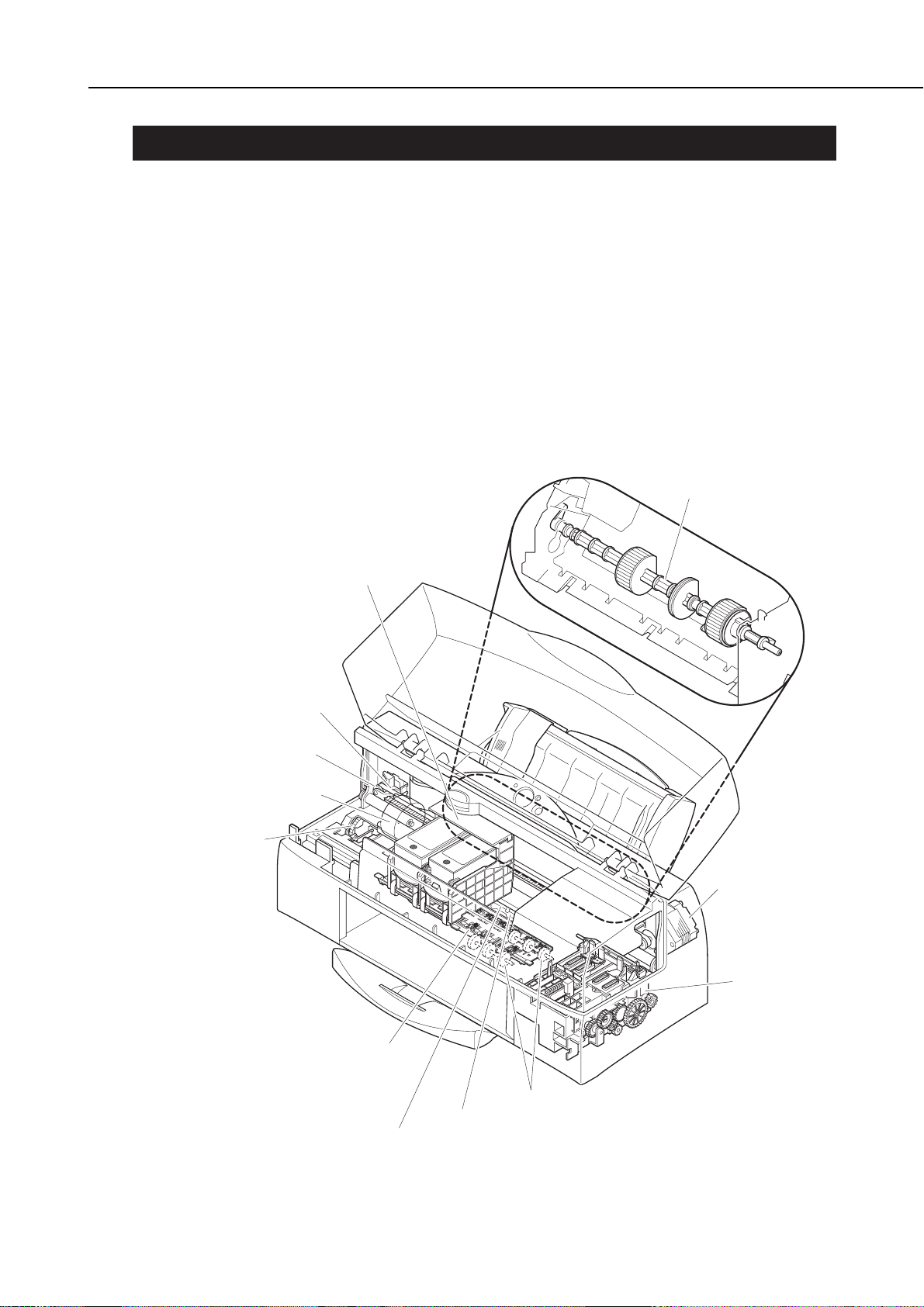
There are moving parts associated with the carriage motor and paper feed motor.
Carriage motor
Carriage belt, idler pulleys, and carriage
Paper feed motor
Paper feed roller, pressure rollers, spurs, pick-up roller, slow down gear, paper output
guide, and purge unit.
Be sure that the front cover is closed so that there is no risk of contacting the moving
parts, except when checking operation during servicing.
Note that the spurs are made of metal with a sharp edge. Be careful not to touch the
spurs with your bare hands.
1-1
BJC-7100
Part 1: Safety and Precautions
Figure 1-1 The Printer's Moving Parts
Pickup Roller
Carriage Belt
Idler Pulley
Paper Feed Motor
Slow Down Gear
Carriage
Carriage Motor
Purge Unit
Spur Unit
Page Eject Roller
Feed Roller
Pressure Roller
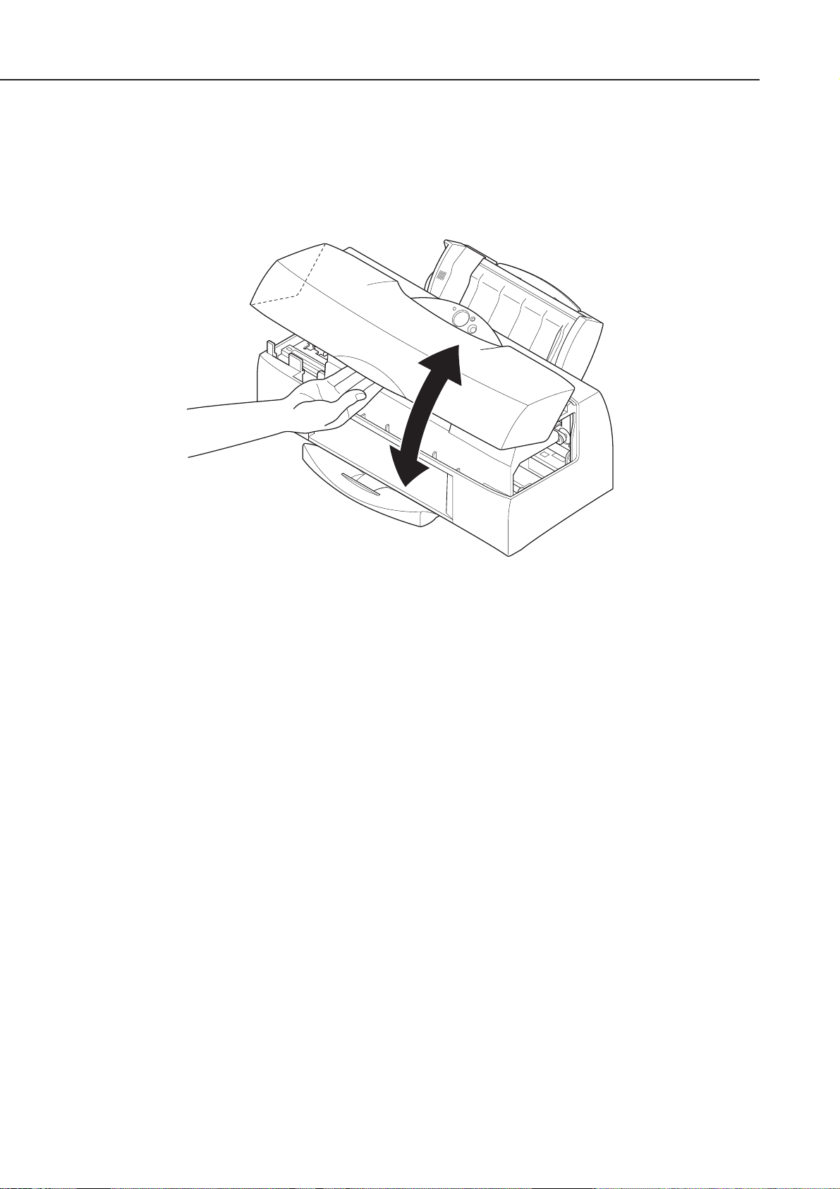
1.2 Front Cover
Hold the front part of the front cover to open and close the cover.
Be careful not to pinch your fingers between the front and main cover when closing the
front cover.
Part 1: Safety and Precautions
BJC-7100
1-2
Figure 1-2 Front Cover
1.3 Ink Stains
1.3.1 Ink path
Be careful not to touch the ink path as it may stain your hands, clothes, printer, work
table etc., during servicing.
The ink path consists of the BJ cartridge nozzles, head cap, waste ink tube, head
wiper, cleaner unit, maintenance jet receiving section, and waste ink absorber.
CAUTION
Although the ink and ink optimizer for plain paper are not harmful to the
human body, they contain organic solvents indicated on the package.
Avoid getting the ink into your mouth and eyes, and store out of reach of
children.
If ink does get into your eyes, wash with plenty of water and consult a
doctor. If for some reason a large amount of ink is swallowed, consult a
doctor immediately.
Give the doctor the information on the BJ cartridge package.
This ink contains dyes, that cannot be removed from clothing, etc.
1-3
BJC-7100
Part 1: Safety and Precautions
Figure 1-3 Ink Path
Wiper for Plain Paper
Ink Optimizer
Maintenance Jet Receiving
Section for Plain Paper
Ink Optimizer
Maintenance Jet
Receiving Section
for Ink
Maintenance Jet Absorber
for Plain Paper Ink Optimizer
BJ Cartridge
Carriage
Color: Photo Head (Nozzles)
Black: Ink Optimizer Head (Nozzles)
Cleaner Unit
Head Cap
Purge Unit
Waste Ink Tube
Waste Ink & Waste Ink Optimizer Absorber
Head Wiper
Maintenance Jet
Absorber for Ink
The joints and ink outlets of the respective ink tanks of the photo BJ cartridge [BC62e Photo] and color BJ cartridge [BC-61] are also part of the ink path and must be
handled with care.
Unless absolutely necessary, do not remove the ink tanks from a BJ cartridge, since
air may enter the ink path and have a negative effect on print quality.
The BJC-7100 uses a variety of inks and an ink optimizer for printing on
plain paper. The ink optimizer is an almost colorless, transparent fluid.
We will refer to the ink optimizer for plain paper simply as ink optimizer or
just optimizer for simplicity purposes. We will also refer to the various
colored inks and the ink optimizer for plain paper simply as "inks".
1.3.2 Ink mist
The BJ cartridge ejects ink onto the paper. After prolonged or heavy-duty use of the
printer, a small amount of ink mist splattered during printing can dirty the printer
such as the platen.
Turn off the power, open the front cover, and clean the dirty parts with a soft moist
cloth. This is to prevent dirtying the paper, your hands, and clothing from touching
these parts.
Part 1: Safety and Precautions
BJC-7100
1-4
Figure 1-4 BC-62e Photo and BC-61
Figure 1-5 Ink Mist
Ink Outlets
Joints
Head (Nozzles)
Ink Outlets
Joints
Head (Nozzles)
BC-62e Photo BC-61
Front Cover
Platen
Paper Output
1.4 Live Parts
When the plug of the printer's AC adapter is plugged into a live power outlet, the power
supply unit of the printer is live regardless of the power being set to ON or OFF using
the
POWER
button.
Be careful not to get on electric shock if you are checking the printer operation with the
covers off.
CAUTION
Do not attempt to dismantle the AC adapter. The mains AC voltage is
supplied to the primary side of the AC adapter. To prevent risk of electric
shock, do not attempt to dismantle the AC adapter to check its operation,
etc.
If faulty, the AC adapter must be replaced as one unit (service part). The
structural components, including the case, are not available individually
as service parts. Do not attempt to dismantle the AC adapter.
1-5
BJC-7100
Part 1: Safety and Precautions
Figure 1-6 AC Adapter
1.5 BJ Cartridge Metal Plate
Do not touch the BJ cartridge's metal plate as it may be very hot. The metal plate
heats up during printing and becomes particularly hot during heavy duty printing.
CAUTION
Danger! High Temperature!
Do not touch.
The printer has the following protective mechanisms to detect overheating:
1. Overheat detection when replacing cartridge
If overheating is detected, a beeper sounds four times and the carriage
does not return to the replacement position. This is to prevent the user
from touching the BJ cartridge's metal plate.
Resume the cartridge replacement after leaving the cartridge to cool for
several minutes.
2. Overheat detection during normal printing
The carriage movement and the paper eject operation are continued
while the printing is stopped. Depending on the outcome of the ink-out
detection after completion of printing a page, a beeper sounds to
indicate the status of the error.
Ink available: BJ cartridge overheat error (beeper sounds 7 times)
Ink out: Ink-out error (beeper sounds 3 or 4 times)
When a BJ cartridge overheat error occurs, leave the cartridge to cool
for several minutes then press the
RESUME
button.
These protective mechanisms are based on the temperatures detected by
the sensors in the BJ head.
If the protective mechanism is activated and normal operation cannot be
resumed after cooling the head for several minutes, see
"Part 5: 6.
TROUBLESHOOTING" (page 5-13)
.
For details of ink-out detection, see
"Part 4: 5.2.3 Ink-out detection" (page 4-48)
.
Part 1: Safety and Precautions
BJC-7100
1-6
Metal Plate
Figure 1-7 BJ Cartridge Metal Plate
2. MACHINE PRECAUTIONS
2.1 BJ Cartridge Handling
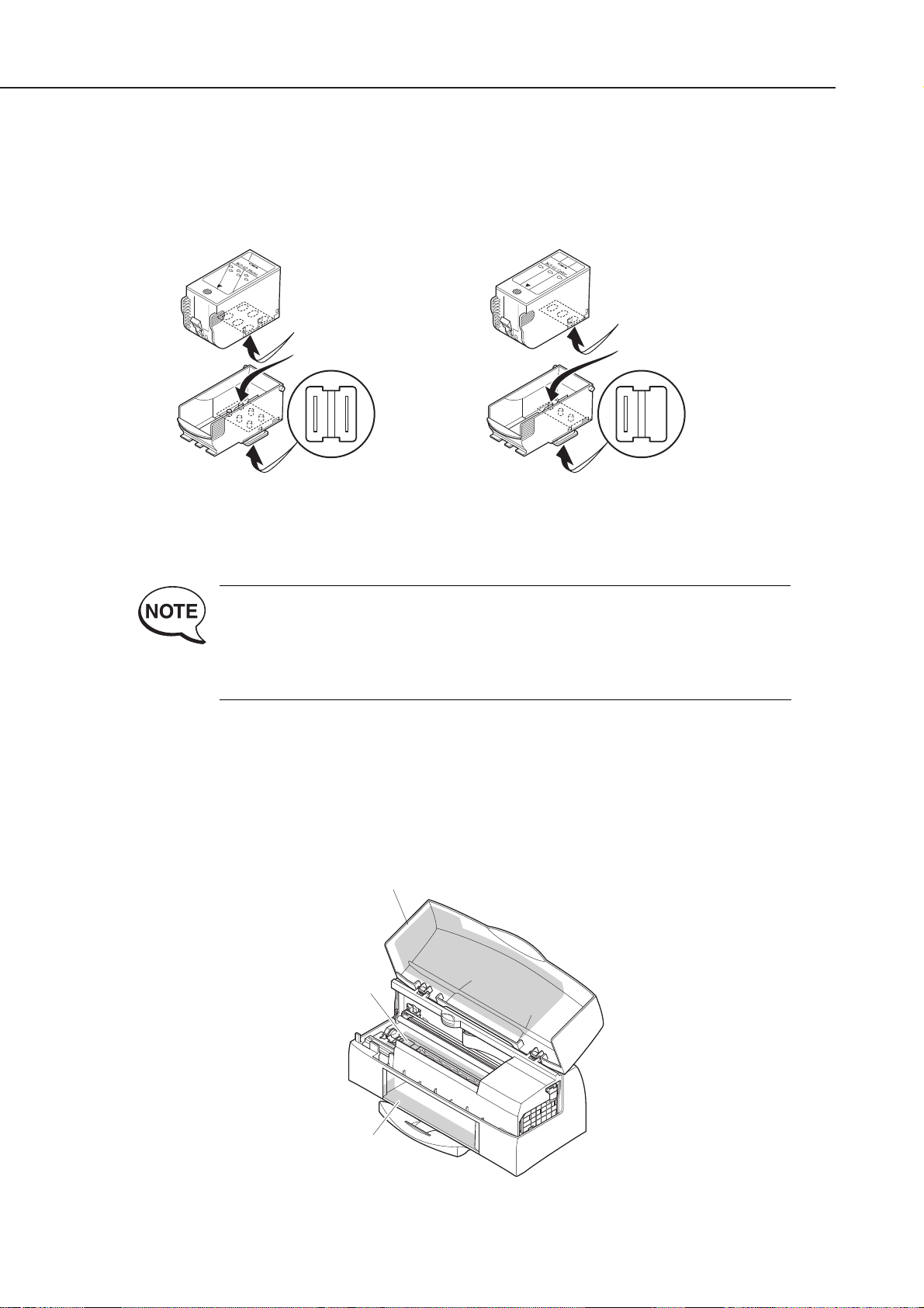
2.1.1 Unpacking the BJ cartridge
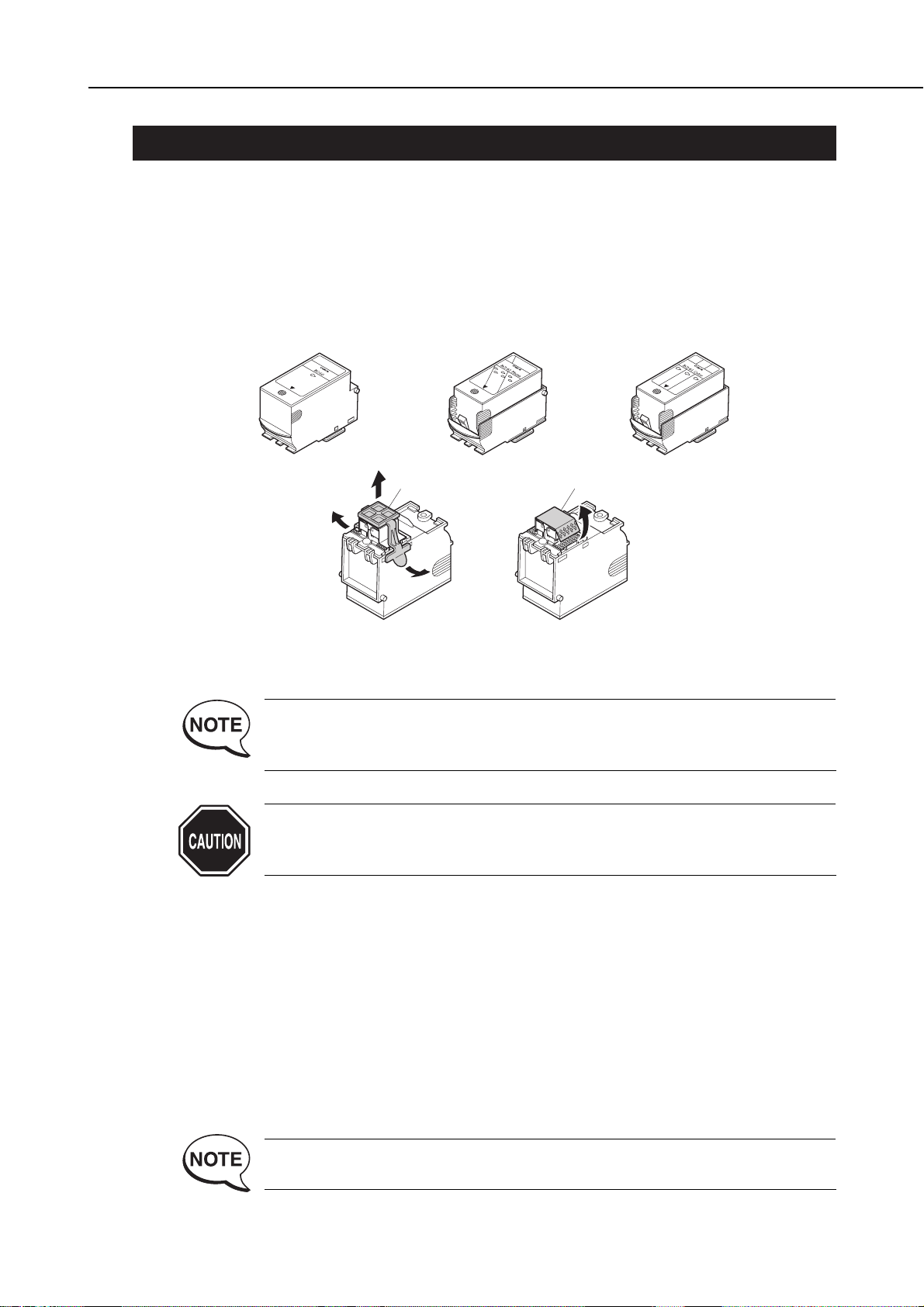
Do not unpack the BJ cartridge until you are ready to use it.
Before installing the BJ cartridge in the printer, remove the cap protecting the nozzles
and gently peel off the protective tape.
Do not attempt to reuse the cap or the tape after they have been removed, as doing so
may cause faulty printing.
If you replace the cap on the color BJ cartridge or photo BJ cartridge, the
sponge in the cap may cause the colors to bleed into each other. The
nozzles may also become clogged.
Always move the carriage to the BJ cartridge replacement position before
attempting to remove or install a cartridge. Failure to do so may result in
damage to the BJ cartridge.
2.1.2 BJ cartridge protection
To prevent the nozzles from clogging, never touch or wipe the nozzles, joint pipes, or
ink tank outlets with your bare hands or with tissue paper, etc. After removing the
cap and peeling off the protective tape from a BJ cartridge, promptly install the
cartridge in the printer or store it in the cartridge holder. If the BJ cartridge is not
capped or stored in the cartridge holder, the nozzles may clog due to dried out ink or
dust, etc.
Do not attempt to leave color BJ cartridges or photo BJ cartridges with their ink tanks
removed.
BJ cartridges cannot be disassembled, reassembled, or washed.
Clogged nozzles cause faulty printing. If this problem persists even after
the nozzles are cleaned, replace the BJ cartridge.
1-7
BJC-7100
Part 1: Safety and Precautions
Figure 1-8 Removing the BJ Cartridge Cap and Tape
BC-60
BC-62e Photo
Head Cap
Protective Tape
BC-61
2.1.3 Power on/off
When the printer is turned off with the
POWER
button, the printer automatically caps
the BJ cartridge's nozzles for protection and to prevent ink leakage.
If the AC adapter is unplugged before the printer is turned off with the
POWER
button, the nozzles may not be capped. In this case, plug the AC adapter again, start
up the printer and turn off the printer with the
POWER
button before unplugging the
power cord. Note that, if you unplug the power during the recovery operation and
then leave the printer, the purge unit may be damaged.
If the nozzles are not capped, the ink might dry out and clog the nozzles or
leak from the cartridge.
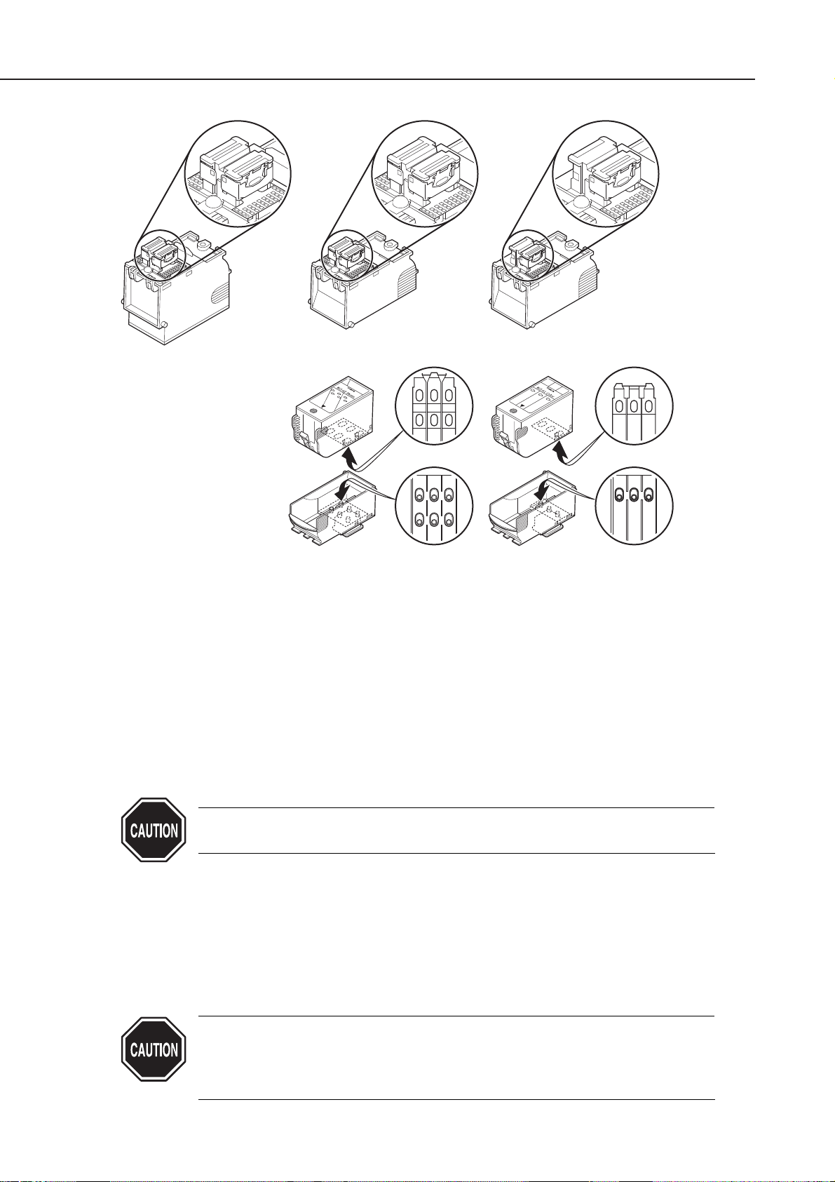
2.1.4 When not using the printer
Keep the BC-60 BJ cartridge installed in the printer even when the printer is not in
use. The BC-62e Photo and BC-61 BJ cartridges can be left installed in the printer or
stored in the cartridge holder. This also applies when carrying, transporting, or
storing the printer.
If the BJ cartridge is taken out of the printer, dried ink or dust may clog
the nozzles, resulting in inconsistent printing.
If the printer is moved or transported with no cartridge installed, ink may
leak from the cap mechanism.
Part 1: Safety and Precautions
BJC-7100
1-8
Figure 1-9 BJ Cartridges
BC-60 BC-62e Photo
Ink Outlets
Joints
BC-61
Ink Outlets
Joints
2.1.5 Ink electroconductivity
The ink used in the BJ cartridge can conduct electricity. If any ink leaks into the
printer's mechanical parts, use paper towels, etc., to wipe clean. If the ink leaks onto
the printer's electrical components, use tissue paper, etc., to wipe clean. If the ink
gets to the IC chips on the PCB, or if it is too difficult to thoroughly clean off the ink,
replace the respective parts.
Never connect the printer's power cord if ink has leaked inside the printer.
It may damage the circuitry.
2.2 Ink Tank Handling
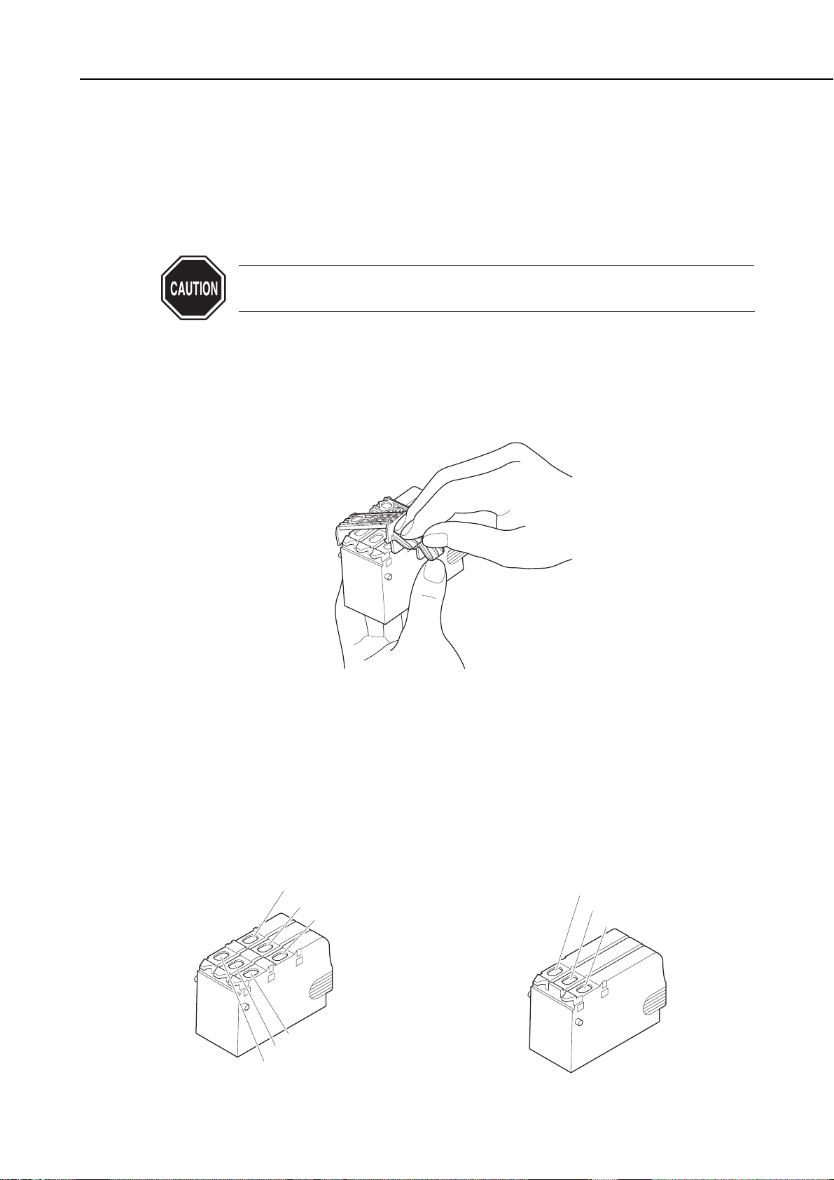
2.2.1 Unpacking the ink tank
Do not unpack the ink tank until you are ready to use it.
Before installing it in the color BJ cartridge, remove the cap covering the ink outlets.
2.2.2 Preventing clogging
To prevent poor ink suction due to clogging of the joints in the BJ cartridge, never
touch the ink tank's ink outlets. After removing the cap from the ink tank, promptly
install the ink tank in the BJ cartridge to prevent the nozzles from clogging due to
dried-out ink, dust, etc. Do not remove an ink tank from a BJ cartridge unless you
are replacing it.
1-9
BJC-7100
Part 1: Safety and Precautions
Figure 1-10 Removing the Ink Tank Cap
Figure 1-11 The Ink Outlets on Ink Tank
BCI-62 Photo
Photo Cyan Ink Outlet
Photo Magenta Ink Outlet
Photo Yellow Ink Outlet
Yellow Ink Outlet
Magenta Ink Outlet
Cyan Ink Outlet
BCI-61 Color
Cyan Ink Outlet
Magenta Ink Outlet
Yellow Ink Outlet
2.3 Printer Handling
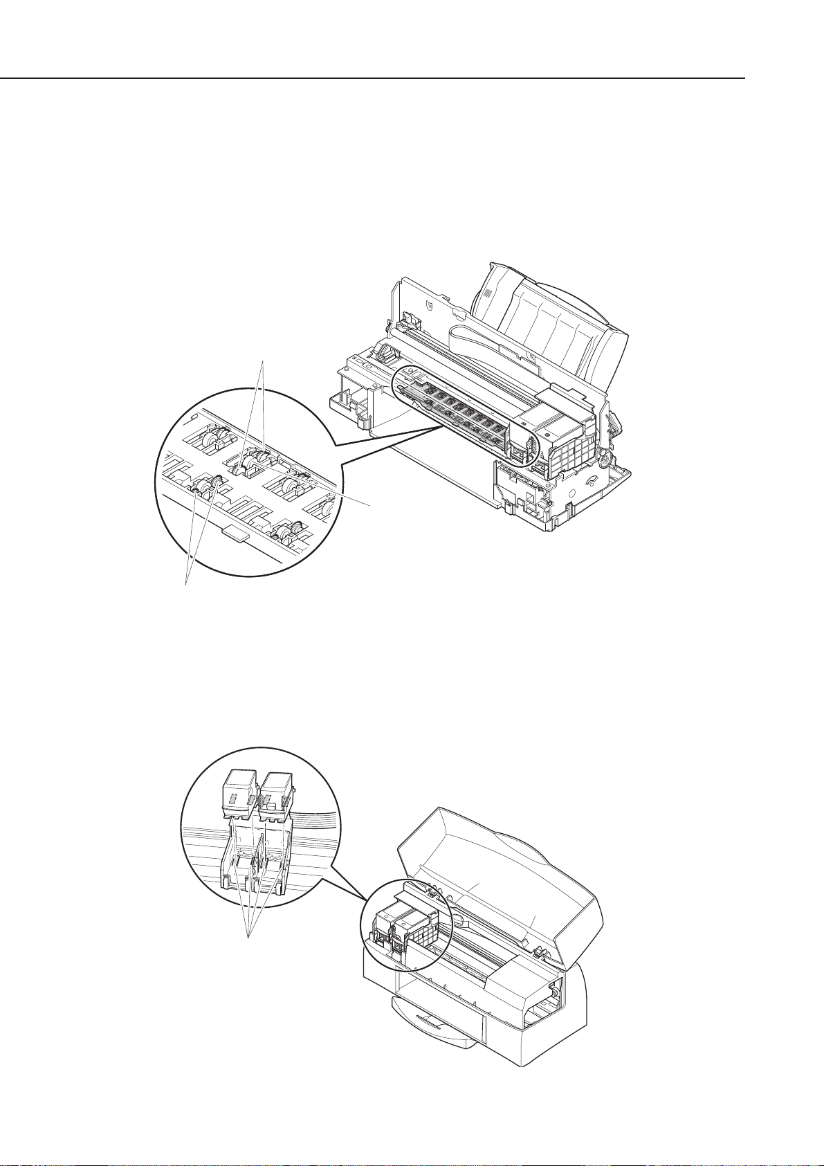
2.3.1 Spurs
Take care not to bend the tips of the spurs.
The spurs that transport and eject the paper after printing are very small and can
easily be deformed.
If a spur is deformed, its contacting surface with the printed paper increases, creating
a dotted line.
2.3.2 Damage due to static electricity
The static charge accumulated by your body from clothing can damage electrical
components and alter their electrical characteristics.
Never touch the carriage contacts or BJ cartridge contacts.
Part 1: Safety and Precautions
BJC-7100
1-10
Figure 1-12 Spurs
Figure 1-13 Contacts
Double Spurs
Spur Cleaner
Spurs
Contacts
2.3.3 Ink leakage and dry-out
Make sure a BJ cartridge is installed before turning off the power, using the
POWER
button.
When you turn off the printer using the
POWER
button, the printer automatically
performs the following operations:
Cleaning
Any ink left in the purge unit or in the nozzles of the BJ cartridge is removed.
Capping
To prevent ink dry-out, the BJ cartridge's nozzles are capped automatically and the
carriage is locked in position.
If you unplug the AC adapter by mistake, plug the power cord again, turn the power
on and then off again using the
POWER
button, then unplug the AC adapter.
If you turn the power off or unplug the AC adapter when the BJ cartridge has been
removed, the nozzles will not be automatically capped or the carriage locked in
position, and hence there is a risk of ink leaking or dry-out.
If the power cannot be turned on due to some failure, manually move the
carriage belt or the carriage itself to the capping position. For details, see
"Part 3: 2.2 Manual Capping" (page 3-13).
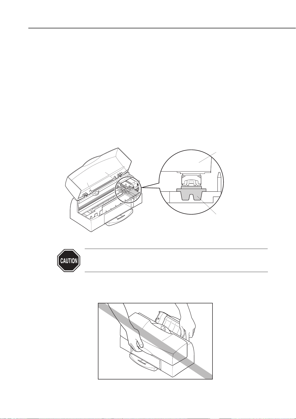
2.3.4 Carrying the printer
Hold both sides of the bottom of the printer to carry it. Note that inserting your hand
into the paper outlet may dislodge or damage the paper guides.
1-11
BJC-7100
Part 1: Safety and Precautions
Figure 1-14 Capping Position
Figure 1-15 Carrying the Printer
BJ Cartridge
Head Cap
3. NOTES ON SERVICING
3.1 EEPROM Data
The printer stores the function settings and keeps track of various information
including the total sheets printed, the number of cartridge replacements, the total
waste ink amount, and the head position adjustment values. The data is stored in the
EEPROM on the logic board.
Note the following precautions during servicing:
1) Before servicing
You can check the EEPROM data with a test print. The total sheets printed can give
you an idea of how much the printer has been used.
2) During logic board replacement
Always replace the waste ink absorber when replacing the EEPROM.
If you do not replace the waste ink absorber, the data on waste ink amount will differ
from the amount of ink that can be absorbed by the waste ink absorber. There is
therefore a risk of ink leaking.
When replacing the logic board, be sure to reset all the data. Because the data on
new EEPROMs is undefined, they cannot be used until they are reset. For details of
handling EEPROMs, see
"Part 3: 3.4 EEPROM" (page 3-19)
.
3) After waste ink absorber replacement
After replacing full waste ink absorbers, reset the EEPROM's waste ink counter.
4) If you accidentally reset the EEPROM's waste ink amount data or all data
Once reset, the EEPROM data cannot be restored. If you accidentally reset the
EEPROM, you must take the same steps as when replacing the logic board.
After the EEPROM is reset, the data it contained cannot be printed out
with a test print. If you want to check the stored data, be sure to make a
test print before resetting the EEPROM.
Note that you cannot reenter the data from the printer's control panel or
by using a computer.
If the EEPROM is faulty, or all data is reset, all data is lost. Whenever
possible, restore all data such as the head alignment to the user's
settings.
During operation, the waste ink amount (EEPROM data) is automatically
updated. An error message is displayed and operation halted when the
waste ink absorber is nearly full. If this occurs, refer to
"Part 5: 6.
TROUBLESHOOTING" (page 5-13)
.
See
"Part 3: 3.8.3 Printing EEPROM data" (page 3-23)
for how to make a test
print of the stored data.
You can choose to either reset the waste ink counter or all data. See
"Part
3: 3.8.2 Resetting EEPROM data" (page 3-22)
for details.
Part 1: Safety and Precautions
BJC-7100
1-12
3.2 Service Mode of Printer Driver
There are certain printer driver control functions, described below, that are, in
principle, hidden from the end user. These service mode functions, which must be
used with caution, are provided for service purposes only.
See
"Part 3: 3.3.2 Service mode of printer driver" (page 3-18)
for details.
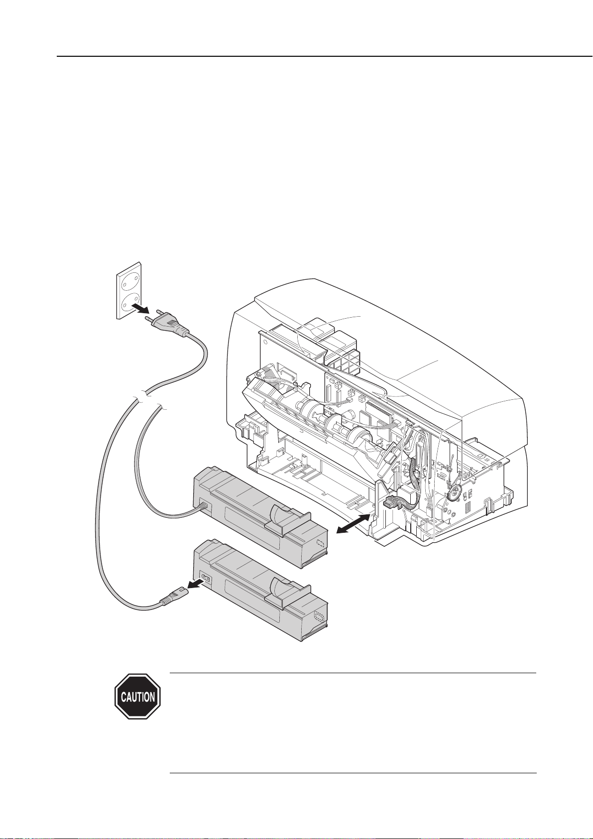
3.3 Protecting the Power Supply
The power supply for the BJC-7100 printer consists of an AC adapter and a power supply
circuit on the logic board. Provided the AC supply is connected, the printer power supply
is live whether or not the power is set ON or OFF using the
POWER
button.
Always unplug the AC adapter from the power outlet before connecting it to or
disconnecting it from the printer. Ignoring this warning can result in damage and
failure of the printer power supply.
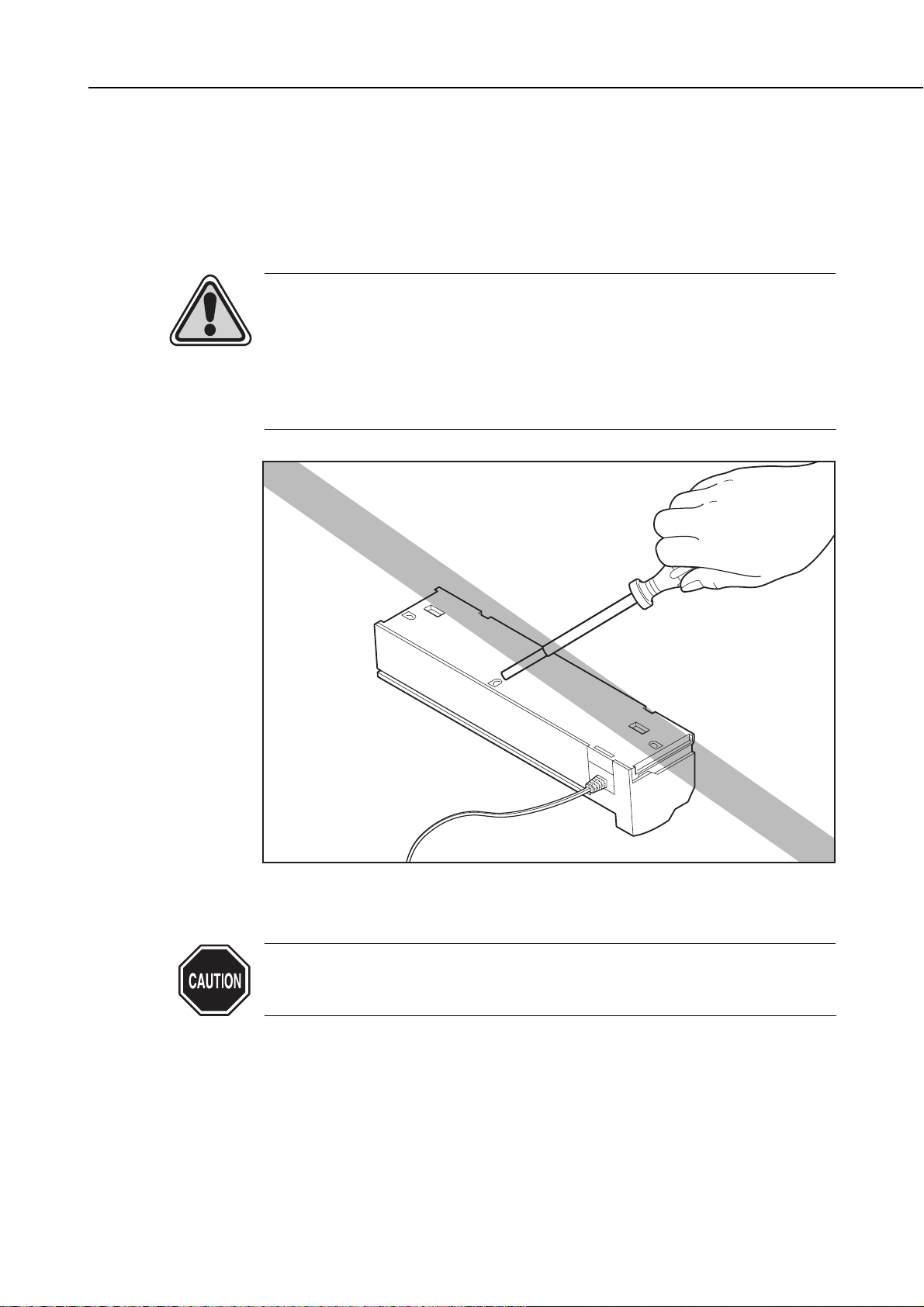
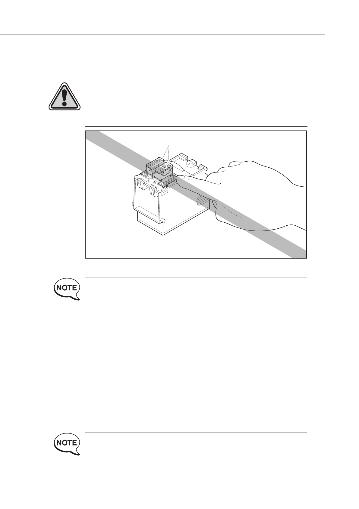
When moving the carriage by hand when, for example, manually capping the
ink nozzles or releasing the carriage lock, do so slowly while paying attention
to the operation of the carriage motor; the back electromotive force generated
by moving the carriage horizontally may damage the motor control board.
If it is necessary to move the carriage horizontally fairly frequently, such
as when replacing or adjusting the carriage, temporarily disconnect the
carriage motor connector from the control board.
1-13
BJC-7100
Part 1: Safety and Precautions
Figure 1-16 Protecting the Power Supply
STEP 1-1
USA Only
or
STEP 2
STEP 1-2
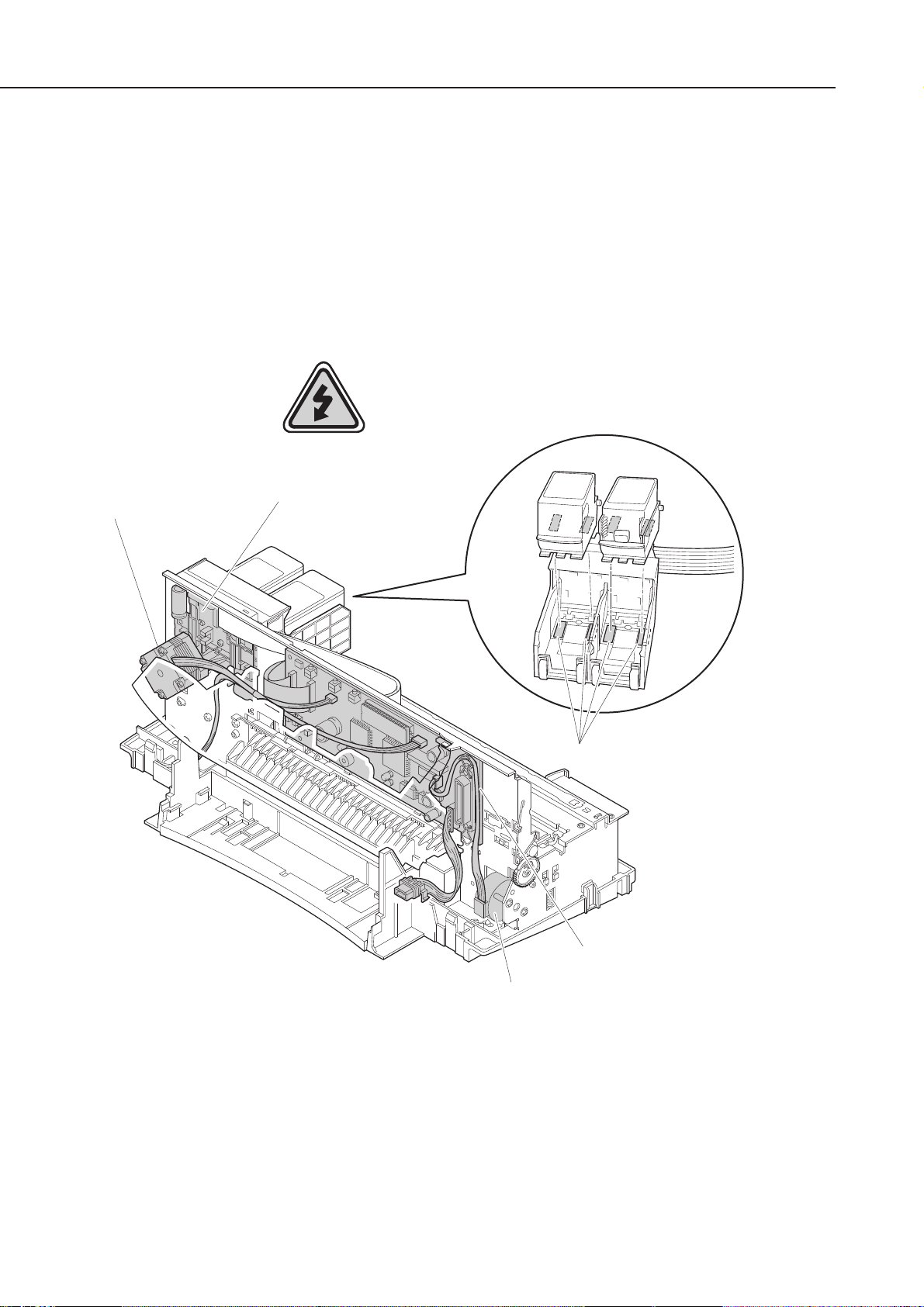
3.4 Static Electricity
The electrostatic charge accumulated in clothing can damage electrical components
and alter their electrical characteristics.
Before disassembling the printer to service it, use a wriststrap or other grounded metal
object to discharge the static electricity. The following parts must not be touched
before you have discharged the static electricity from your body:
• Logic board, carriage board
• Motor control board
• Cable connectors and contacts
• BJ cartridge signal contacts
Part 1: Safety and Precautions
BJC-7100
1-14
Figure 1-17 Electrical System of Printer
Static Damage!
Carriage Motor
Carriage Board
BJ Cartridge Signal Contacts
Logic Board
Paper Feed Motor

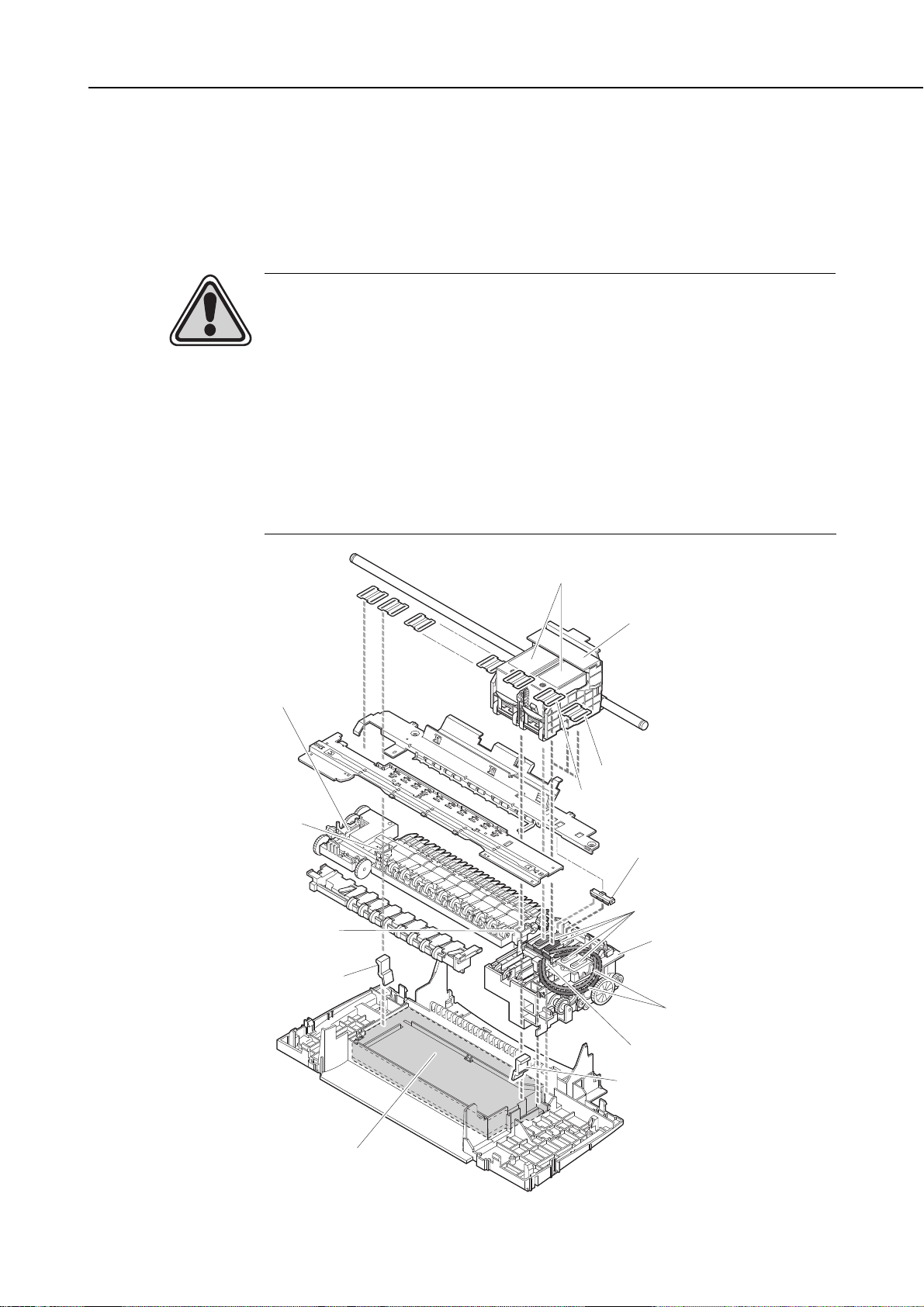
3.5 Disassembly and Assembly
3.5.1 Parts that cannot be disassembled
Do not disassemble the ribbon cable to the head on the carriage unit. The position in
relation to the contacts with the BJ cartridge is factory adjusted, and cannot be
readjusted during printer servicing.
In addition, do not attempt to disassemble the AC adapter, BJ cartridge, or ink tanks.
In principle, do not loosen any of the screws painted red in the printer mechanism
(except when adjusting the head gap using the jig). The red screws hold the adjustable
plate that determines the gap between the nozzles of the BJ cartridge and the platen.
This gap is adjusted to the optimal value when the printer leaves the factory.
In addition to the above, do not attempt to disassemble any parts not
shown disassembled in the exploded diagrams in the parts catalog.
Failure to observe this warning may result in those parts not functioning
as originally intended after they are reassembled.
3.5.2 Parts requiring careful attention during disassembly and assembly
The printer has many parts that can be damaged during disassembly and assembly.
For details, see
"Part 5: 4. DISASSEMBLY AND REASSEMBLY" (page 5-4)
. Please read
this section carefully before attempting to disassemble and assemble the printer.
The printer also has many plastic parts. When disassembling the printer, take care
not to break or bend the plastic hooks.
Some plastic parts contain glass fibers for extra rigidity and precision, but
since their viscosity is low, the plastic hooks can break easily when
excessive force is used. Do not pull a plastic hook with excessive force
while unhooking it.
3.6 Self-Diagnosis
The printer has a self-diagnosis feature to detect hardware defects. The results of the
self-diagnosis are indicated on the LED on the control panel, and by the beeper. For
details, see
"Part 3: 3.1 Error Indications" (page 3-14).
1-15
BJC-7100
Part 1: Safety and Precautions
Figure 1-18 Parts that Cannot be Disassembled
Head AlignmentAdjuster Plate
AC Adapter
Red Screw
Carriage Unit
BJ Cartridge
Ink Tank
Red Screw
Head AlignmentAdjuster Plate

Part 1: Safety and Precautions
BJC-7100
1-16
This page intentionally left blank

Part 2
PRODUCT
SPECIFICATIONS
Page
2 - 1 1. PRODUCT OUTLINE
2 - 1 1.1 Outline
2 - 2 1.2 Features
2 - 3 1.3 BJ Cartridge
2 - 6 1.4 SB-60 BJ Cartridge Container
2 - 6 1.5 Consumables
2 - 7 2. SPECIFICATIONS
2 - 7 2.1 General Specifications
2 -10 2.2 Paper Specifications
2 -12 2.3 Interface Specifications


1. PRODUCT OUTLINE
1.1 Outline
The BJC-7100 is a personal desktop color bubble-jet printer that uses a new 600dpi BJ
cartridge and technology to achieve outstanding print quality and photographic
realism. The printing process uses an ink optimizer to enable water resistance printing
on plain paper.
The BJC-7100 printer uses new accurate photo BJ cartridge BC-62e Photo and new
paper eject mechanisum to achieve high speed printing with high quality print.
The BJC-7100 printer, which is easy to operate under Microsoft Windows, and is
compatible with the Internet and multimedia tools such as digital cameras, is targeted
at a wide range of users in the small-office and personal-computer environments who
require high-quality full color printing.
The ink optimizer is an almost colorless, transparent fluid. For simplicity
in this manual, we refer to the ink optimizer for plain paper simply as ink
optimizer or just optimizer. We also refer to the various colored inks and
the ink optimizer for plain paper simply as "inks".
2-1
BJC-7100
Part 2: Product Specifications
Figure 2-1 Printer Appearance
REPLACE
Button
POWER
Indicator
ERROR
POWER
BJ Cartridge Container
Indicator
RESUME
Button
Cover
Button
Paper Guide
Paper Rest
Auto Sheet Feeder
Paper Output Tray
Manual Feed Guide
Manual Feed Slot
AC Adapter

1.2 Features
1. The new 600dpi BJ cartridge provides high-resolution printing at up to 1200 (H) ×
600 (V) dpi when using the exclusive printer driver.
There are three types of new BJ cartridge: BC-60, BC-62e Photo, and BC-61. (Note
that the BJ cartridge configuration differs according to the country.)
2. The printer is equipped with two BJ cartridges.
The BC-60 is normally installed in the printer and either the BC-62e Photo or BC-61
is installed as required for the type of printing to be carried out.
3. The print process uses an ink optimizer to enable maximum water resistance when
printing on plain paper (and envelopes).
In this new printing process, the surface of the paper is coated with the ink optimizer
prior to being printed. The ink optimizer is discharged from the special BJ head of
the BC-60.
4. The straight manual insertion path allows printing on a wide variety of papers.
In addition, the automatic platen-head adjustment mechanism obviates the need for
levers for selecting papers and platen-head gap.
5. The printer performs high speed print; HQ: 5.8ppm, HS: 7.6ppm (BK; PC magazine)
6. The printer is equipped with an ink-out detection function based on the conduction
of static electricity.
An electrical signal is input to the ink path in the BJ cartridge. This signal is picked
up by the electrode on the carriage, and the signal level is used to determine the
existence or absence of ink.
7. The printer is equipped with an IEEE1284-compatible bidirectional parallel interface.
This interface is compatible with nibble mode and ECP mode.
8. The built-in control mode is the Canon extended mode.
The host computer sends print signals in Canon extended mode, generated by the
special printer driver.
9. The printer is supplied with Windows 3.1, Windows 95 and Windows 98 special
printer driver.
10. The printer is powered by an AC adaptor, installed by manufucturing.
The ink optimizer printing process can be used in both monochrome and
color printing when the printer driver is set to plain paper (including
postcards and envelopes) in all but Draft mode. It cannot be used if the
driver is set to other than plain paper (special papers and film, etc.).
The ink-out detection mechanism confirms that the BJ cartridge is out of
ink. The mechanism does not measure the amount of ink remaining in
the cartridge and therefore does not necessarily indicate an error at the
point where print quality deteriorates as the ink runs out.
Part 2: Product Specifications
BJC-7100
2-2

1.3 BJ Cartridge
1.3.1 Black BJ cartridge (BC-60)
The BC-60 BJ cartridge is used for monochrome printing and for printing using the
ink optimizer. It is a head and ink tank integrated type, disposable BJ cartridge
consisting of a unified BJ head and ink tanks for black ink and ink optimizer.
There are two parallel BJ heads, each with 304 nozzles. One head supplies ink while
the other supplies the ink optimizer.
Replace the BJ cartridge if either the black ink or ink optimizer runs out, or if
satisfactory printing cannot be achieved even after the stipulated cleaning operations
have been performed. Also replace the cartridge if more than 12 months has elapsed
after the seal is broken.
The BC-60 BJ cartridge will print approximately 870 pages of a standard 1500character print pattern (Default setting of Text mode).
2-3
BJC-7100
Part 2: Product Specifications
Figure 2-2 Black BJ Cartridge (BC-60)
1
N.C.
2
4
3 5
,
8
7 9 6
121011
14 15 13
17 16 18
2021 22 19
,
24 23
25
27 26
N.C.
View
2726
N.C.
2423
25
20212219
171618
141513
12 10 11
,
8796
,
435
12
N.C.

1.3.2 Photo BJ cartridge (BC-62e Photo)
The BJ head for the BC-62e Photo has been modified to considerably improve the ink
jet emission precision.
The BC-62e Photo BJ cartridge is used for photo-realism (super photo mode) (when
printing photographs with substantial numbers of half-tones and light colors). The
cartridge consists of a main unit that separates the BJ heads, and disposable ink
tanks (BCI-62 photo).
There are two parallel BJ heads, each with 240 nozzles. One head supplies color inks
while the other supplies photo inks. Both BJ heads have three vertical rows of 80
nozzles each for yellow, magenta, and cyan.
The total 6 ink tanks for color and photo inks are integrated.
The BC-62e Photo BJ cartridge works by layering the photo inks, which are about
1/3rd the density of the color inks, thereby enabling pale colors and halftones to be
printed. The color inks are used to print denser colors and fill larger areas with one
color.
Replace the ink tanks if any of the 6 inks runs out, or if satisfactory printing cannot
be achieved even after the stipulated cleaning operations have been performed. If you
still cannot obtain satisfactory print quality, replace the BJ cartridge. Also replace the
cartridge if more than 12 months has elapsed after the seal is broken. (Replace the
ink tank 6 months after the seal is broken.)
The BC-62e Photo BJ cartridge will print approximately 90 pages per tank of a
standard photo print pattern (Reference data).
Part 2: Product Specifications
BJC-7100
2-4
Figure 2-3 Photo BJ Cartridge (BC-62e Photo)
1
N.C.
4
8
7 9 6
,
14 15 13
17 16 18
2021 22 19
,
24 23
2
3 5
121011
25
27 26
N.C.
N.C.
2726
2423
25
20212219
,
171618
141513
12 10 11
8796
,
435
12
N.C.
View

1.3.3 Color BJ cartridge (BC-61)
The BC-61 BJ cartridge is used for color printing (denser colors and filling larger
areas with color). The cartridge consists of a main unit that separates the BJ heads,
and disposable ink tanks (BCI-61 Color).
The BJ head has 240 nozzles supplying the color inks. There are three vertical rows
of 80 nozzles each for yellow, magenta, and cyan. The 3 ink tanks are integrated.
Replace the ink tanks if any of the 3 inks runs out, or if satisfactory printing cannot
be achieved even after the stipulated cleaning operations have been performed. If you
still cannot obtain satisfactory print quality, replace the BJ cartridge. Also replace the
cartridge if more than 12 months has elapsed after the seal is broken. (Replace the
ink tank 6 months after the seal is broken.) The BC-61 BJ cartridge will print
approximately 275 pages per tank of a standard color print pattern.
1.3.4 BJ cartridge vs print mode
The inks are used in different ways according to the selected print mode, as shown in
the table below.
●●: Used ▲▲: Used only for plain paper, envelopes ✕: Not used
When you use the BC-62e Photo BJ cartridge to print in color using only the normal
color inks and not the photo inks, the normal color inks will run out and the ink
tanks will have to be replaced before the photo inks are used up.
The estimated print quantity for the BC-60 (approximately 870 pages in
monochrome) is for printing only in monochrome and assumes that the
ink optimizer is not used up by color printing. If the ink optimizer is used
in color printing, the cartridge may not print as many pages and it may be
necessary to replace the BC-60 even if you do not print in monochrome at all.
When handling BJ cartridges and ink tanks, observe the notes in
"Part 1:
2.1 BJ Cartridge Handling" (page 1-7)
.
2-5
BJC-7100
Part 2: Product Specifications
Figure 2-4 Color BJ Cartridge (BC-61)
TABLE 2-1 BJ CARTRIDGE VS PRINT MODE
Print Mode
Fast
Standard (Fast)
Standard (High Quality)
High Quality
Fine
Black Ink
●●
●●
●●
●●
●●
Ink Optimizer
✕
▲▲
▲▲
▲▲
▲▲
Color Ink
●●
●●
●●
●●
●●
Photo Ink
✕
✕
✕
●●
●●
Color Ink
●●
●●
●●
●●
●●
BC-60 BC-62e Photo BC-61
1
N.C.
2
4
3 5
8
7 9 6
,
121011
14 15 13
17 16 18
2021 22 19
,
24 23
25
27 26
N.C.
View

1.4 SB-60 BJ Cartridge Container
The SB-60 cartridge container is for storing the BC-62e Photo or BC-61 BJ cartridge—
whichever is not currently being used.
The SB-60 cartridge container is supplied with the printer, and can also be bought as
optional equipment.
After placing a cartridge in the holder, be sure to close the lid securely. Failure to do so
may result in the nozzles clogging due to dried ink.
The SB-60 cartridge container can be used to store either the BC-62e Photo or BC-61
BJ cartridge. Store either of the cartridges in the holder if you have removed the
protective caps and tape.
The cartridge container can be installed on the printer.
Note that the BC-60 cartridge cannot be stored in the SB-60 cartridge
container, and is always installed in the printer.
1.5 Consumables
1.5.1 BJ cartridge
The BJ cartridges (BC-60, BC-62e Photo, and BC-61) used in the BJC-7100 printer
are supplied as consumables. Except for the packaging, these consumables are
identical to the BJ cartridges supplied with the new printer.
The BC-62 Photo used in the BJC-700J Printer cannot be used on this printer. If the
BC-62 Photo is installed on BJC-7100, printing is carried out, however, print quality
may deteriorate drastically.
1.5.2 Ink tank
The BCI-62 Photo ink tank for the BC-62e Photo cartridge, and the BCI-61 Color ink
tank for the BC-61 cartridge are both supplied as consumables.
Always replace the ink tanks if one of the colors runs out, or satisfactory print quality
cannot be achieved even after the stipulated cleaning operations. If, after replacing
the ink tanks, you still cannot obtain satisfactory print quality, replace the BJ
cartridge. Note that the ink tanks can only be used for 6 months after the seal is
broken.
Part 2: Product Specifications
BJC-7100
2-6
Figure 2-5 BJ Cartridge (SB-60)
Figure 2-6 Ink Tanks
BCI-62 Photo BCI-61 Color

2. SPECIFICATIONS
2.1 General Specifications
1. Type
Desktop serial color bubblejet printer
2. Operating mode
Canon extended mode
3. Print resolution
1200 (H) × 600 (V) dpi max.
4. Printing speed
Burst (BC-60 monochrome)
HQ: 480cps, HS: 720cps
Throughput
Monochrome printing: HQ: Approx. 5.8ppm, HS: Approx. 7.6ppm
Color printing: HQ: Approx. 0.5 to 2.1ppm, HS: Approx. 1.3 to 4.4ppm,
FINE: Approx. 0.26 to 0.9ppm
HQ: Default setting of Text mode
HS: Default setting of Draft mode
FINE: Default setting of Auto mode
5. Printing width
218mm max. (Maximum print width when Letter+ size is selected)
6. Line pitch
n/600inch (where n is programmable)
7. Print direction
Select either of Unidirectional or BIdirectional as the printing mode. (See
"Part 4: 2.2
Print Mode" (page 4-8)
)
8. Bit image printing
Data matrix: Canon extended mode: Raster image format
Resolution: Canon extended mode: 300, 600, and 1200dpi
9. Buffer
256KB
10. Interface
IEEE1284-compatible parallel interface
11. Interface cable
Material: AWG28 or thicker
Type: Twisted pair shielded cable
Length: 2.0m max.
12. Interface connectors
Printer: Amphenol 57-40360 or equivalent
Cable: Amphenol 57-30360 or equivalent
2-7
BJC-7100
Part 2: Product Specifications

13. Paper Feeding method
ASF and manual feed: Plain paper, high-resolution paper, envelopes,
transparencies, back print film, glossy photo paper,
fabric sheets, high-gloss photo film and T-shirts transfer
Manual feed only: Other papers
14. Sheet feeder capacity
Plain paper: 130 max.
High-resolution paper: 100 max.
Envelopes: 15 max.
Transparencies: 30 max.
Back print film: 10 max.
Glossy photo card: 10 max.
Glossy photo paper: 1
High-gloss photo film: 1
Fabric sheets: 1
T-shirts transfer 1
15. Paper sizes
Cut sheets: Size: A4, B5, A5, Letter, Legal, A4+, Letter+
Weight: 64g/m2to 105g/m2[17 to 28 lbs] (auto sheet
feeder),
64g/m2to 550g/m2[17 to 146 lbs] (manual feed)
Thickness: 0.8mm max. (manual feed)
Envelopes: COM#10 and DL-size
Recommended plain paper: Canon bubble jet paper LC-301
High-resolution paper: High-resolution paper for color BJ HR-101
Glossy photo paper: Glossy photo paper for color BJ GP-301
High-gloss photo film: High-gloss photo film for color BJ HG-201
Glossy photo card: Glossy photo card for color BJ FM-101
Transparencies: Transparencies for color BJ CF-102
Back print film: Back print film for color BJ BF-102
Fabric sheets: Fabric sheets for color BJ FS-101
T-shirts transfer: T-shirts transfer for color BJ TR-201
16. BJ cartridge
Black BJ cartridge BC-60
Nozzles: Two rows of 304 nozzles × 1 color
Ink colors: Black ink and ink optimizer (semi-transparent)
Service life: Approx. 870 pages per cartridge (when printing standard
1500-character pattern)
Photo BJ Cartridge BC-62e Photo
Nozzles: Two rows of 80 nozzles × 3 colors
Ink colors: Yellow, magenta, and cyan
Photo yellow, photo magenta, and photo cyan
Service life (Reference data): Approx. 90 pages per tank (when printing standard
photo pattern)
Head service life: Approx. 2000 pages (when printing standard photo pattern)
Part 2: Product Specifications
BJC-7100
2-8

Color BJ cartridge BC-61
Nozzles: One row of 80 nozzles × 3 colors
Ink colors: Yellow, magenta, and cyan
Service life: Approx. 275 pages per tank (when printing standard color pattern
at 7.5% duty per color)
Head service life: Approx. 2000 pages (when printing standard color pattern at 7.5%
duty per color)
17. Acoustic noise level
Approx. 48dB (based on ISO9296 sound pressure level)
18. Operating environment
During operation: Temperature: 5°C to 35°C
Humidity: 10% to 90% (no condensation)
During storage: Temperature: 0°C to 35°C
Humidity: 5% to 90% (no condensation)
19. Power supply
USA/Canada: 120VAC, 60Hz
UK/Australia: 240VAC, 50Hz
Europe/China: 220VAC, 50Hz
20. Power consumption
During soft-power off mode: Approx. 7W max.
During idle: Approx. 8W max.
During printing: Approx. 45W max.
21. External dimensions
467mm (w) × 313mm (d) × 218mm (h)
(with paper output tray in storage position)
22. Weight
Approx. 6.4kg (with AC adaptor installed)
23. Sensor functions
Paper out detection: Yes
BJ cartridge installation detection: Yes
Waste ink amount detection: Yes
Paper width detection: No
BJ cartridge identification: Yes
Ink-out detection: Yes
2-9
BJC-7100
Part 2: Product Specifications

2.2 Paper Specifications
2.2.1 Paper types
●● : OK ✕: NG
*1: A4+ size paper is a Canon original size paper that, measuring 222.7 × 355.6mm, is
slightly larger than A4 size paper. The A4+size paper allows you to print to the full A4
size. The LTR+ size, measuring 228.6 × 337.8mm, similarly allows you to print to the
full LTR size.
Part 2: Product Specifications
BJC-7100
2-10
Plain paper
Type
Class 1
Class 2
Name
Canon PB (NSK)
Canon PB (NDK)
Canon NP (Kangas)
Canon NP (Neusiedler)
Canon NP (BoiseCascade)
Canon BJ Paper LC-301
Xerox 4024 (75g/m2)
Xerox 4024 (95g/m2)
Plover Bond
Size
A4, B5, A5
A4, B5, A5
A4, B5, A5
A4, B5, A5
LTR, LGL
A4, B5, LTR, LGL
LTR, LGL
LTR, LGL
LTR, LGL
Sheet Feeder
●●
●●
●●
●●
●●
●●
●●
●●
●●
Manual Feed
●●
●●
●●
●●
●●
●●
●●
●●
●●
Special Papers
Type
Coated Paper
High-Resolution Paper
Transparency
BPF
Glossy Photo Paper
High-Gloss Photo Film
Envelopes
Fabric Sheets
Other Paper
T-Shirts transfer
Name
LC-301
HR-101
CF-102
BF-102
GP-301
HG-201
COM#10
DL
FS-101
TR-201
Size
A4, LTR
A4, LTR
A4, LTR
A4, LTR
A4, LTR, A4+*1, LTR+*
1
A4, LTR
241 × 105mm
220 × 110mm
241 × 356mm
A4, A3
Sheet Feeder
●●
●●
●●
●●
●●
●●
●●
●●
●●
✕
●●
Manual Feed
●●
●●
●●
●●
●●
●●
●●
●●
●●
●●
●●
TABLE 2-2 PAPER SPECIFICATIONS

2.2.2 Printing range
2-11
BJC-7100
Part 2: Product Specifications
Figure 2-7 Printing Area
3mm
7.0mm
A4, A5 and B5 Sizes
3.4mm
3.4mm
A4+and Letter (LTR+) Sizes
(1) 12.0mm
(2) 21.0mm
(1) 22.6mm
(2) 21.6mm
29.3mm
Letter (LTR) and Legal (LGL) Sizes
3mm
7.0mm
6.4mm 6.4mm
Fabric Sheets
(1) 12.0mm
(2) 21.0mm
(1) 22.6mm
(2) 21.6mm
25.4mm
5.1mm
A4+ 5.9mm
Letter+ 5.1mm
: Recommended Printing Area
: Printable Area
(1) Monochrome Printing
(2) Color or Photo Printing
28.0mm
3.0mm
7.0mm
6.4mm
Envelopes
6.4mm
43.6mm
31.4mm
(1) 12.0mm
(2) 21.0mm
(1) 22.6mm
(2) 21.6mm
COM#10: 31.4mm
DLsize: 10.4mm

2.3 Interface Specifications
1) Interface type
Bidirectional parallel interface (IEEE1284 compatible)
2) Signal level
Input
TTL level: Input signals other than to data bus
"Low" level: +0.0V to +0.6V "High" level: +2.4V to +5.0V
TTL level: Data bus
"Low" level: +0.0V to +0.8V "High" level: +2.2V to +5.0V
Output
"Low" level: +0.0V to +0.4V
"High" level: +2.4V to +5.25V
3) IO
Each signal is pulled up to +5V.
4) Interface cable
Material: AWG No. 28 or thicker (American Wire Gauge)
Type: Shielded twisted pair cable
Length: 2.0m max.
5) Interface connectors
Printer: Amphenol 36-pin 57-40360 or equivalent
Cable: Amphenol 36-pin 57-30360 or equivalent
6) IO signals and pin configuration
*1: N.C.: No Connection *2: -RET are All Connected to Gnd.
*3: Connected to +5.0V Through 390 Resistance.
*4: Connected to +5.0V Through 3.3k Resistance.
Part 2: Product Specifications
BJC-7100
2-12
TABLE 2-3 IO SIGNALS IN COMPATIBLE MODE
Pin No.
1
2
3
4
5
6
7
8
9
10
11
12
13
14
15
16
17
18
Signal
Date-Strobe
Data 1
Data 2
Data 3
Data 4
Data 5
Data 6
Data 7
Data 8
Acknlg
Busy
PE
Select
Auto Feed XT
N.C.*
1
Gnd
Gnd
Peripheral Logic High
*
3
I/O
IN
IN
IN
IN
IN
IN
IN
IN
IN
OUT
OUT
OUT
OUT
IN
...
...
...
...
Signal
Data Strobe-RET*
2
Data 1-RET
Data 2-RET
Data 3-RET
Data 4-RET
Data 5-RET
Data 6-RET
Data 7-RET
Data 8-RET
Acknig-RET
Busy-RET
PE-RET
Init
Fault
Gnd
N.C.*
1
Peripheral Logic High
*
4
Select in
I/O
...
...
...
...
...
...
...
...
...
...
...
...
IN
OUT
...
...
...
IN
Pin No.
19
20
21
22
23
24
25
26
27
28
29
30
31
32
33
34
35
36

*1: N.C.: No connection
*1: N.C.: No connection
2-13
BJC-7100
Part 2: Product Specifications
TABLE 2-4 IO SIGNALS IN NIBBLE MODE
TABLE 2-5 IO SIGNALS IN ECP MODE
Pin No.
1
2
3
4
5
6
7
8
9
10
11
12
13
14
15
16
17
18
Signal
HostClk
Data 1
Data 2
Data 3
Data 4
Data 5
Data 6
Data 7
Data 8
PtrClk
PtrBusy
AckDataReq
Xflag
HostBusy
N.C.*
1
Gnd
Gnd
Vcc
Symbol on
Circuit Diagram
[STROBE]
[DATA 1]
[DATA 2]
[DATA 3]
[DATA 4]
[DATA 5]
[DATA 6]
[DATA 7]
[DATA 8]
[ACK]
[BUSY]
[PE]
[SELECT]
[AFXT]
[N.C.]
[GND]
[GND]
[
Peripheral Logic High
]
I/O
IN
IN/OUT
IN/OUT
IN/OUT
IN/OUT
IN/OUT
IN/OUT
IN/OUT
IN/OUT
OUT
OUT
OUT
OUT
IN
...
...
...
...
Pin No.
19
20
21
22
23
24
25
26
27
28
29
30
31
32
33
34
35
36
Signal
Signal Gnd
Signal Gnd
Signal Gnd
Signal Gnd
Signal Gnd
Signal Gnd
Signal Gnd
Signal Gnd
Signal Gnd
Signal Gnd
Signal Gnd
Signal Gnd
Init
DataAvail
N.C.*
1
N.C.*
1
N.C.*
1
1284 Active
Symbol on
Circuit Diagram
[GND]
[GND]
[GND]
[GND]
[GND]
[GND]
[GND]
[GND]
[GND]
[GND]
[GND]
[GND]
[INIT]
[FAULT]
[GND]
[N.C.]
[
Peripheral Logic High
]
[SELECT IN]
I/O
...
...
...
...
...
...
...
...
...
...
...
...
IN
OUT
...
...
...
IN
Pin No.
1
2
3
4
5
6
7
8
9
10
11
12
13
14
15
16
17
18
Signal
HostClk
Data 1
Data 2
Data 3
Data 4
Data 5
Data 6
Data 7
Data 8
PeriphClk
PeriphAck
AckReverse
Xflag
HostAck
N.C.*
1
Gnd
Gnd
Vcc
Symbol on
Circuit Diagram
[STROBE]
[DATA 1]
[DATA 2]
[DATA 3]
[DATA 4]
[DATA 5]
[DATA 6]
[DATA 7]
[DATA 8]
[ACK]
[BUSY]
[PE]
[SELECT]
[AFXT]
[N.C.]
[GND]
[GND]
[
Peripheral Logic High
]
I/O
IN
IN/OUT
IN/OUT
IN/OUT
IN/OUT
IN/OUT
IN/OUT
IN/OUT
IN/OUT
OUT
OUT
OUT
OUT
IN
...
...
...
...
Pin No.
19
20
21
22
23
24
25
26
27
28
29
30
31
32
33
34
35
36
Signal
Signal Gnd
Signal Gnd
Signal Gnd
Signal Gnd
Signal Gnd
Signal Gnd
Signal Gnd
Signal Gnd
Signal Gnd
Signal Gnd
Signal Gnd
Signal Gnd
ReverseReq
PeriphReq
N.C.*
1
N.C.*
1
N.C.*
1
1284 Active
Symbol on
Circuit Diagram
[GND]
[GND]
[GND]
[GND]
[GND]
[GND]
[GND]
[GND]
[GND]
[GND]
[GND]
[GND]
[INIT]
[FAULT]
[GND]
[N.C.]
[
Peripheral Logic High
]
[SELECT IN]
I/O
...
...
...
...
...
...
...
...
...
...
...
...
IN
OUT
...
...
...
IN

7) Description of input/output signals
Compatible Mode
Data Strobe [Input]
This signal is used to read DATA1 to DATA8. The signal becomes valid after the
BUSY signal goes Low and the printer outputs an ACKNLG signal. This signal is
normally High. After it goes Low, the printer receives data. When the signal
remains Low, the printer does not operate until it goes High.
Data1 to 8 [Input]
The printer receives data with the DATA STROBE signal.
The state of each bit of the signal must be maintained for at least 0.5µs from the
rising edge of the DATA STROBE signal.
Acknlg [Output]
This signal is a response signal to the DATA STROBE signal.
The host computer does not send the next DATA STROBE signal until this signal is
sent.
When the power is turned on or the BUSY signal goes Low for the input of the INIT
signal, this signal is sent regardless of the DATA STROBE signal.
Busy [Output]
When this signal is High, the printer is BUSY; when Low, the printer is READY.
The printer receives data at least 1 Byte when Data Stobe signal is input in the case
Busy signal goes to "H" regardless of receiving data.
The signal is High in the following cases:
• When receiving data
• When input buffer is full
• When INIT signal is input
• When carriage is in cartridge replacement position
• During manual cleaning
• When an error occurs (paper-out, paper jam, etc.)
• During soft power on/off sequence
• During internal initialization
PE [Output]
This signal goes High when the printer cannot feed paper. The BUSY signal goes
High and the SELECT and FAULT signals go Low.
This signal goes Low when the reset key was pressed and paper is loaded and fed.
The FAULT and SELECT signals then go from Low to High.
If paper is not ejected (paper jam) after an eject operation, this signal and the BUSY
signal go High, and the SELECT and FAULT signals go Low. In this case, the signals
do not change even if the paper is removed manually.
Select [Output]
The printer is READY when this signal is High.
This signal goes Low when an error occurs (paper-out, paper jam, etc.) or when the
carriage is in the cartridge replacement position.
Fault signal goes to low 50ms after Busy signal goes to high.
Auto Feed XT [Input]
This signal is only used for the transition from compatible mode to negotiation mode.
Part 2: Product Specifications
BJC-7100
2-14

Init [Input]
When it changes to Low, this signal sets the printer in the BUSY state, then resets
the printer by changing from Low to High.
The pules width of this signal is requiired longer than 5 micro seconds.
On completion of initialization, the head retreats to the home position and the
default print mode is selected.
Fault [Output]
This signal changes to Low when the printer detects an error and when the carriage
is in the cartridge replacement position to inform the host computer of the error
state.
Select in [Input]
This signal is only used for the transition from compatible mode to negotiation mode.
Nibble Mode
HostClk [Input]
This is the STROBE signal to read DATA 1 to DATA 8. When in negotiation phase
this is the trigger signal to send the protocol confirmation to the printer.
In nibble mode, this signal is always High so that the printer does not fetch data.
Data 1 to 8 [Input]
The data bus is not used in nibble mode.
Ptr Clk [Output]
The printer requests the host computer to read the data by making the Ptr Clk
signal Low in the reverse data transmission phase. After finishing reading, the host
computer notifies the printer of completion of data receiving by making the Host
Busy AUTO FEED XT signal High.
Ptr Busy [Output]
This signal outputs the data to be sent to the host computer in the reverse data
transmission phase. First, bit 3 of the transmission byte data is output, followed by
bit 7.
Ack Data Req [Output]
This signal outputs the data to be sent to the host computer in the reverse data
transmission phase. First, bit 2 of the transmission byte data is output, followed by
bit 6.
This signal is used as the trigger signal to inform the host computer of the printer’s
condition in the negotiation phase.
Xflag [Output]
This signal outputs the data to be sent to the host computer in the reverse data
transmission phase. First, bit 1 of the transmission data is output, followed by bit
5.
This signal informs the host computer whether the printer supports nibble mode in
the negotiation phase.
The printer supports nibble mode when this signal level changes to Low at the same
time the Ack Data Req (PE) signal rises.
2-15
BJC-7100
Part 2: Product Specifications

Host Busy [Input]
Indicates that the host is ready to receive the data from the printer by making the
Host Busy signal Low in the reverse data transmission phase. After that, it goes
High when data is received from the printer to verify receiving data.
This signal changes to High in response to the PtrClk (ACKING) signal changing to
Low to change to the reverse data transmission phase.
Init
This signal is not used in nibble mode.
DataAvail [Output]
This signal outputs the data to be sent to the host computer in the reverse data
transmission phase. First, bit 0 of the transmission data is output, followed by bit
4.
Informs the host computer if there is reverse transmission data or not in the
negotiation phase. If data is ready to be sent to the host computer, this signal
changes to Low.
1284 Active (Input)
This signal confirms that the printer is an IEEE 1284-compatible device. This signal
goes High at the start of the negotiation phase and remains High in nibble mode to
indicate that the printer is operating in bidirectional mode. It changes to Low in the
termination phase.
ECP mode
HostClk [Input]
This is the signal used in handshaking with PeriphAck (BUSY) signal when data is
sent from the host computer to the printer.
This signal changes to Low when data has been output to the data bus (Data1 to 8)
This signal changes to High in response to the PeriphAck (BUSY) signal rising. It
remains High in the reverse data transmission phase.
Data 1 to 8 [Input/Output]
These are input data signals when data is sent from the host computer to the
printer.
In the reverse data transmission phase, these are output signals, and the printer
outputs data to the host computer using this data bus.
Periph Clk [Output]
This signal is always High when data is sent from the host computer to the printer.
In the reverse data transmission phase, this signal changes to Low to indicate that
data is output to the host computer. This signal changes to High in response to the
HostAck (AUTO FEED XT) signal changing to High.
Periph Ack [Output]
When data is sent from the host computer to the printer, this signal changes to Low
when the printer is ready to receive data.
When the data has been received from the host computer, this signal changes to
High.
In the reverse data transmission phase, this signal indicates if the information
output from the printer to the data bus is command information or data (Low:
Command information; High: data).
Part 2: Product Specifications
BJC-7100
2-16

Ack Reverse [Output]
This signal remains High when data is sent from the host computer to the printer. It
remains Low in the reverse data transmission phase.
When switching from the forward to reverse data transmission phase, this signal
changes to Low, to indicate that a request to switch modes has been received, in
response to the fall of the Reverse Request (INIT) signal, which is sent by the host
computer to request the switch.
This signal changes to High, to indicate that the request to switch modes has been
received, when the Reverse Request (INIT) signal rises.
Xflag [Output]
This signal is always High in ECP mode.
Host Ack [Input]
When data is sent from the host computer to the printer, this signal indicates
whether the signal information on the data bus is data or command information
(Low: Command information; High: data).
In reverse data transmission, this signal is used for handshaking with the Periph
Clk (ACKNLG) signal.
When the host is ready to receive data from the printer, this signal changes to Low,
then changes to High when the data has been received.
Reverse Req [Input]
This signal changes to Low during the recovery phase (resending data) when data is
sent from the host computer to the printer.
This signal changes to High in response to the lowered Ack Reverse (PE) signal.
This signal changes to Low on transition from the idle state in the forward data
transmission phase to the reverse data transmission phase (when data is sent from
the printer to the host computer).
When Low, this signal indicates reverse data transmission.
The signal changes to High on transition from reverse data transmission to forward
data transmission.
Periph Req [Output]
This signal changes to Low when, during forward data transmission, the printer
requests reverse data transmission.
When the host computer changes from forward data transmission to reverse data
transmission, this signal changes to High at the same time as the Ack Reverse (PE)
signal in response to the fall in the Reverse Request (INIT) signal, which requests the
switch in modes by the host computer.
1284 Active (Input)
This signal goes High at the start of the negotiation phase and remains High in ECP
mode to indicate that the printer is operating in bidirectional mode. It changes to
Low in the termination phase on exiting ECP mode.
2-17
BJC-7100
Part 2: Product Specifications

Part 2: Product Specifications
BJC-7100
2-18
Figure 2-8 Compatible Mode
Figure 2-9 Nibble Mode
Figure 2-10 ECP Mode
Data 1-8
STROBE
BUSY
ACKNLG
1284 Active
0.5µs
0.5µs
0.5µs
Min.
Min.
Min.
4µs (When HS mode is invalid)
Min.0.8µs
Ack Data Req
Data (1 to 8)
Host Busy
Host Clk
Ptr Clk
Ptr Busy
nData Avail
Xflag
1284 Active
nAck Reverse
Data (1 to 8)
Host Ack
Host Clk
0000 0000
Printer Busy
Ptr Host
With data
Nibble mode
Support
Invalid
0001 0000
Bit2 Bit6
Bit3 Bit7
Bit0 Bit4
Bit1 Bit5
TP TP TP
Byte0
nCmd nCmd
Byte1
TP: minimum set up
Periph Clk
Periph Ack
nPeriph Req
Xflag
ECP mode Support
TP
TP
TP
TP
TP: minimum set up

Part 3
OPERATING
INSTRUCTIONS
Page
3 - 1 1. PRINTER SETUP
3 - 1 1.1 Unpacking
3 - 2 1.2 Installation Location
3 - 3 1.3 Installation
3 - 8 1.4 Turning Printer Power On and Off
3 - 9 1.5 Loading Printer Paper
3 -10 1.6 Names of Parts and Their Functions
3 -12 2. TRANSPORTING THE PRINTER
3 -12 2.1 Transporting the Printer
3 -13 2.2 Manual Capping
3 -14 3. PRINTER SERVICING FUNCTIONS
3 -14 3.1 Error Indications
3 -16 3.2 Warning Indications
3 -17 3.3 Function Settings
3 -19 3.4 EEPROM
3 -19 3.5 Cleaning the BJ Cartridge
3 -20 3.6 Test Printout
3 -20 3.7 Pickup Roller Cleaning Function (HR-101)
3 -21 3.8 Service Mode


1. PRINTER SETUP
1.1 Unpacking
After unpacking, make sure the items below have been included:
3-1
BJC-7100
Part 3: Operating Instructions
Figure 3-1 Packaging
Packing
Instruction Manual
Instructions/
Driver Software
BJ Cartridge
BJ Cartridge Container
Packing
Packing
Packing
Packing
Carton
Packing
Tapes
Tapes
Tapes
Tapes

1.2 Installation Location
To ensure optimum performance, install the printer where there is adequate space.
It is also important that you install the printer where the vibration caused by the
carriage movements will not cause problems.
The figure illustrates the printer dimensions.
Use the printer where the ambient temperature is between 5°C and 35°C
and the ambient humidity is between 10% and 90% (no condensation).
Do not install the printer where it is subject to direct sunlight or where it
may be subject to rapid fluctuations in temperature, such as close to air
conditioners, etc. Also, do not leave the printer in motor vehicles, etc.,
where it may be subject to a rapid rise in temperature.
Do not install the printer where it may be subject to excessive amounts of
dust, or subject to sea breezes or other sources of salinity.
Do not install close to TV, speakers, or other sources of storing magnetic
fields.
Install the printer on a level and stable surface.
Avoid locations subject to vibration.
If you install the printer on a standard PC rack, make sure the rack itself
is well secured to avoid excessive vibration during printing.
Part 3: Operating Instructions
BJC-7100
3-2
Figure 3-2 Printer Dimensions
Approx. 300mm Max.
Approx. 600mm Max.
467mm

1.3 Installation
Set up the printer as follows.
1.3.1 Connecting the interface cable
1) Make sure both the printer and host PC are OFF.
2) Connect the interface cable to the interface connector on the printer. Lock the
connector clips.
3) Connect the other end of the interface cable to the host PC.
1.3.2 Connecting the power supply
1) Connect the power cord to the AC adaptor, then plug the AC power plug into a wall
outlet.
2) Press the printer
POWER
button. The printer beeper sounds and the power lamp
blinks.
3) After the printer has initialized itself, the carriage moves to the left for the BJ
cartridge to be installed.
3-3
BJC-7100
Part 3: Operating Instructions
Figure 3-3 Connecting the Interface Cable
Figure 3-4 Connecting the Power Supply
1. Connect the cable to the printer 2. Connect the cable to the computer
1. Connect the
power cord to
the AC adaptor.
2. Plug the power plug
into a wall outlet.
3. Press the
POWER
button

1.3.3 Installing the BJ cartridge
1) Removing the BJ cartridge protectors
Remove the BJ cartridge from the package, then remove the cap and tape on the
nozzles, as shown in the figure.
Do not reuse the cap and tape. It can clog the nozzles or mix the ink
colors.
Do not touch the nozzles when removing the tape as doing so may result
in the head becoming scratched and dirt adhering to the head, resulting in
poor printing.
Do not shake the BJ cartridge after removing the cap and tape as doing so
may result in ink spillage.
2) Installing the BJ cartridge
Open the printer’s front cover and install the BJ cartridge on the carriage.
Install the BC-60 on the left holder and the BC-62e Photo (or BC-61) on the right
holder.
After installing the cartridge, press the
REPLACE
button. The beeper sounds once
and, after about 15 seconds, the carriage returns to the capping position.
Part 3: Operating Instructions
BJC-7100
3-4
Figure 3-5 Removing Cap and Tape from BJ Cartridge
Figure 3-6 Installing BJ Cartridges
Head Cap Protective Tape
BC-60
BC-62e Photo
or BC-61
REPRACE
Button

3) Aligning the print heads
Because two BJ cartridges are installed in the printer, differences in how they are
secured and in the cartridges themselves can shift the way ink is ejected onto the
paper. To even out any differences and ensure satisfactory print quality, follow the
procedure below for adjusting the relative positions of the print heads after
completing the setup procedure on the PC.
1) Load two or more sheets of standard A4-size plain paper into the sheet feeder.
2) Following the instructions on the Printer Driver's control sheet, print a Print Head
Alignment Pattern.
3) Check the printed patterns to select the optimum A (vertical), B (horizontal), C
(bidirectional 1) and D (bidirectional 2) alignment values.
4) Following the instructions on the Printer Driver's control sheet, print a HighResolution Adjustment Pattern.
5) Check the printed pattern to select the optimum E (horizontal 1), F (bidirectional
1), G (horizontal 2) and H (bidirectional 2) adjustment.
6) Following the instructions on the Printer Driver's control sheet, quit the print
head alignment procedure.
7) You can print the nozzle check pattern to check the print head alignment values
after completing this procedure. To print the nozzle check pattern, refer to
3.8
Service Mode (Page 3-21)
.
3-5
BJC-7100
Part 3: Operating Instructions
Figure 3-7 Checking Print Head Alignment
Standard Mode
Fast Mode
(C) Bidirectional 1
(A) Vertical alignment
value (-3 to +3)
(E) Horizontal 1
alignment value
(-3 to +3)
(F) Bidirectinal 1
alignment value
(B) Horizontal alignment
value (-7 to +7)
(G) Horizontal 2
alignment value
(-3 to +3)
alignment value
(-7 to +7)
(-3 to +3)
(H) Bidirectional 2
alignment value
(-3 to +3)
(D) Bidirectional 2
alignment value
(-7 to +7)

1.3.4 Replacing the ink tanks
You can replace the ink tanks of the BC-61 and BC-62e Photo BJ cartridges (not the
BC-60 BJ cartridge). Replace the ink tanks as described below.
1) When to replace the ink tank
Replace the ink tank in any of the following cases: the ink runs out, the ink tank is
out of its package for over six months, and the printing quality does not improve
even after the head is cleaned.
The color ink tanks of the BC-61 and BC-62e Photo contain multiple colors; if one
ink color runs out, the entire color ink tank must be replaced.
2) Removing an ink tank
Press the
REPLACE
button to move the carriage to the cartridge replacement
position (you can also use the printer driver).
As shown in Figure 3-8, lift the front of the ink tank to remove the ink tank from the
holder. Do not touch or let your clothing come in contact with the ink feeds on the
ink tank.
3) Installing an ink tank
Remove a new ink tank from its box, then remove the cap from the ink feeds as
shown in Figure 3-9. Install the ink tank in the holder in the reverse procedure from
that described above.
After installing the ink tank in the holder, press the
REPLACE
button to return the
carriage to the capping position.
Part 3: Operating Instructions
BJC-7100
3-6
Figure 3-8 Replacing the Ink Tank
Figure 3-9 Removing Protective Cap from Ink Tank
REPLACE
Button

1.3.5 Cartridge container [SB-60]
The printer is supplied with a container for storing the BC-61 or BC-62e Photo BJ
cartridges for users who are using both the BC-61 and BC-62e Photo. (Note that the
BC-60 cannot be stored in the container.)
When the BC-61 is installed in the printer, the BC-62e Photo is stored in the
container, and vice versa.
The container can be mounted on the back of the printer.
When storing the BC-61 or BC-62e Photo in the container, make sure the
ink tanks are installed in the BJ cartridge holder.
Make sure that the cartridge faces the correct way in the container.
Do not shake or drop the container, as ink may spill.
The BJC-7100 use a range of inks and, when printing on plain paper, an
ink optimizer for plain paper is used. The ink optimizer is an almost
colorless, transparent fluid.
For simplicity in this manual, we refer to the ink optimizer for plain paper
simply as ink optimizer or just optimizer. We also refer to the various
colored inks and the ink optimizer for plain paper simply as "inks".
3-7
BJC-7100
Part 3: Operating Instructions
Figure 3-10 Cartridge Container SB-60
BC-62e Photo or BC-61
Container
Push here
Printer

1.4 Turning Printer Power On and Off
1.4.1 Turning the power on
When the printer is connected to a power supply, press the
POWER
button to turn it
ON. The beeper sounds once and the printer initializes itself.
If no BJ cartridge has been installed, the
POWER
indicator blinks to show that the
printer is waiting for the cartridge to be installed.
If a BJ cartridge has already been installed when the power is turned on, the
POWER
indicator lights to show that the printer is in standby mode.
When the printer is first turned on after leaving the factory, it automatically performs
a cleaning operation. This operation takes about 2 minutes during which the
POWER
indicator blinks to show that cleaning is being performed.
1.4.2 Turning the power off
If the printer is ON, press the
POWER
button to turn the printer OFF.
When you turn the printer off, the printer automatically caps the BJ cartridge.
During this sequence, the
POWER
indicator continues to blink. The
POWER
indicator
turns off on completion of the power off sequence.
Before unplugging the power cable from the wall outlet, make sure that the
POWER
indicator is off.
Do not unplug the power cable from the wall outlet before turning off the
printer using the
POWER
button.
If you unplug the power cable to disconnect the power, the BJ cartridge
capping will not be performed and ink may leak and dry on the nozzles,
deteriorating the print quality.
If you press the
POWER
button to turn off the power during a cleaning operation, the
POWER
indicator will continue to blink until the cleaning operation has been
completed. The power turns off after the cleaning operation has been completed and
the nozzles have been capped. Note that any errors occurring after the start of the
power off sequence are ignored.
Part 3: Operating Instructions
BJC-7100
3-8
Figure 3-11 Incorrect Method of Powering Off

1.5 Loading Printer Paper
To obtain optimum print quality, either use the auto sheet feeder or the manual feed on
the back of the printer, depending on the type of print paper you are using. Because
this printer automatically adjusts the platen-head gap according to the paper being
used, there are no paper selection or head gap levers. Note that the paper rest can also
be extended to support larger paper sizes.
Paper sizes: Auto: 100 to 355.6 (v) × 100 to 241.3 (h) mm
Manual: 150 to 297 (v) × 150 to 241.3 (h) mm
Ream weight: Auto sheet feeder: 64 to 105g/m
2
Manual feed: 64 to 450g/m2(0.8mm thick, max.)
* Indicates papers designed for use in bubble jet printers.
A4+ and LTR+ are Canon original paper sizes.
3-9
BJC-7100
Part 3: Operating Instructions
TABLE 3-1 PRINTER PAPER SETTINGS
Paper Type
Plain Paper
Plain Paper for
Color BJ
Coated Papers
Glossy Photo Paper
High-Gloss
Photo Film
Transparencies
Back-Print Film
Fabric Sheets
T-Shirts Transfer
Glossy Photo Card
Envelopes
Other Papers
64g to 105g/m
2
Ream Weight
LC-301*
HR-101*
GP-301*
HG-201*
CF-102*
BF-102*
FS-101*
TR-201
FM-101
COM#10
DL-size
106g to 450g/m
2
Ream Weight
(0.8mm thick max.)
Size
A4/A5/B5/LTR/LGL
A4/A5/B5/LTR/LGL
A4/A5/B5/LTR
A4/LTR/A4+/LTR+
A4/LTR
A4/LTR
A4/LTR
241 (v) × 356 (h) mm
A4/A3
219.5 (v) × 119.6 (h) mm
241.3 (v) × 105 (h) mm
220 (v) × 110 (h) mm
150 to 297 (v) ×
150 to 241.3 (h) mm
Feed Method
Auto/Manual
Auto/Manual
Auto/Manual
Auto/Manual
Auto/Manual
Auto/Manual
Auto/Manual
Auto/Manual
Auto/Manual
Auto/Manual
Auto/Manual
Auto/Manual
Manual
Sheet Feeder Capacity
Approx. 13mm Max.
Approx. 13mm Max.
100 Max.
1
1
30 Max.
10 Max.
1
1
10 Max.
15 Max.
15 Max.
Figure 3-12 Paper Settings
Paper Guide
Paper Output Tray
Paper Rest
Manual Feed Guide

1.6 Names of Parts and Their Functions
The different parts of the printer and their functions are shown below.
Part 3: Operating Instructions
BJC-7100
3-10
Figure 3-13 Names of Parts and Their Functions (1)
FRONT
Paper Rest
Supprots the stack of paper loaded in the
sheet feeder.
Sheet Feeder
Print paper is loaded in the sheet feeder.
Note that the sheet feeder capacity deffers
according to the type of paper loaded.
Paper Guide
The left edge of the print paper is supported
by the paper guide so that the paper remains
straight as it is fed through the printer
Cover
Open the cover whenever it is necessary to
replace a BJ cartridge, replace an ink tank,
or remove jammed paper.
Paper Output Tray
Receives the printed paper.
When printing large paper sizes, you can
extend the tray to support them.
Operator Panel
OPERATOR PANEL
POWER
Turns the printer on and off.
POWER
Indicates when the printer is on. The
indicator blinks when the printer is receiving
data and when an error occurs.
ERROR
When an error occurs, the
lights or blinks and the buzzer sound. The
number of blinks indicates the type of error
that has occurred.
RESUME
Use the
if a paper jam or other trouble occurs.
Also use the
cleaning the nozzles or cleaning the pickup
roller with a cleaning sheet within HR-101.
Button
Indicator
Indicator
Button
RESUME
RESUME
POWER
ERROR
button to reset the printer
button when manually
indicator

3-11
BJC-7100
Part 3: Operating Instructions
Figure 3-14 Names of Parts and Their Functions (2)
INSIDE
REPLACE
The
from the cartridge replacement position to
the home position or vice versa.
Button
REPLACE
button moves the carriage
BACK
Parallel Interface Connector
Connects the parallel interface to the PC.
Manual Feed Slot
Insert sheets through this slot when
manually feeding paper. Lightly support
the paper while feeding it straight into this
slot.
Manual Feed Guide
Adjust the manual feed guide sothat it is
slighty in contact with the edge of the paper
being manually fed. This ensures that the
paper is fed correctly.
AC Adaptor and Power Cable
Once installed on the printer, the user does
not need to remove the AC adaptor when
disconnecting the power cord.
Plug the power cable into a wall outlet.

2. TRANSPORTING THE PRINTER
When carrying or transporting the printer, keep the BJ cartridge installed in the printer
or stored in the cartridge container.
This prevents the ink from leaking and drying out in the nozzles.
Also when both BC-61 and BC-62e Photo are in use, keep one cartridge installed in the
printer and the other in the container.
2.1 Transporting the Printer
When transporting the printer, follow the procedure below:
1) Press the
POWER
button to turn off the printer.
2) Disconnect the interface cable.
3) Unplug the AC adaptor power cable from the wall outlet.
4) Open the front cover and check that the carriage is locked in the capping position
(right side of printer). If a fault has occurred and the carriage is not in the capping
position, move it manually to the capping position. (See below: Operations performed
only by service personnel)
If a fault has occurred and the user has moved the printer without the carriage being
locked in the capping position, tape the carriage to the opposite side (left side) of the
printer as an emergency measure.
5) Close the front cover
6) Pack the printer in its original packing materials. Be sure to use cushioning
materials.
Part 3: Operating Instructions
BJC-7100
3-12
Figure 3-15 Transporting the Printer
Emergency MeasureCapping Position

2.2 Manual Capping
The BJ cartridges of the BJC-7100 printer can be capped manually only by service
personal.
1) Insert a tweezers into the hole for manual capping positioning and rotate the gears
slowly counterclockwise.
2) When the cap and carriage lock lever are in the lowest position, slowly move the
carriage to the capping position. *
3) Next, use the tweezers to slowly rotate the gears counterclockwise. Stop rotating the
gears when you can see that capping has been completed.
4) The print head is capped and the carriage is locked.
3-13
BJC-7100
Part 3: Operating Instructions
Figure 3-16 Manual Capping Method
* : See "CAUTION" on page 1-13.

3. PRINTER SERVICING FUNCTIONS
3.1 Error Indications
The indicators in combination with the beeper indicate the nature of any error.
There are two types of errors: operator call errors, which can be corrected by the user,
and service call errors, which cannot be corrected by the user. The indicators show
which type of error has occurred. If an operator call error occurs, the indicators light; if
a service call error occurs, the indicators repeatedly blink a specific number of times,
depending on symptoms.
3.1.1 Operator call errors
The error is displayed on the computer screen via the printer driver, and you can
check the status of the error as shown in the table below by the number of times that
the beeper on the main unit sounds. If the error is not corrected by the apparent
means, as indicated by the error display, the fault may be elsewhere. In this case,
refer to
"Part 5: 6. TROUBLESHOOTING" (page 5-13)
.
*1: A waste ink error (service call) will occur if you continue to use the printer.
When using a bidirectional parallel interface (Nibble or ECP Modes), a
description of the error is displayed on the host computer’s screen.
Part 3: Operating Instructions
BJC-7100
3-14
Figure 3-17 Control Panel
Error
Paper-Out or
Paper-Jam
Ink-Out Error
Ink-Out Error
BJ Cartridge
Error
Waste Ink
Alarm *
1
BJ Cartridge
Overheat Error
Error
Indicator
ON
ON
ON
ON
ON
ON
Beeper
Twice
3
times
4
times
5
times
6
times
7
times
Description (User Correction)
No paper loaded for feeding
(Load the printer with paper, then press the
RESUME
button.)
Paper Jam
(Remove the jammed paper, then press the
RESUME
button.)
Black ink or ink optimizer has run out.
(Replace BJ cartridge [BC-60].)
Color or photo ink has run out.
(Replace appropriate BJ cartridge or ink tank.)
BJ cartridge not installed correctly.
(Install BJ cartridge correctly, then press
REPLACE
button.)
Waste ink or waste ink optimizer exceeds 95% printer
capacity. (Press
RESUME
button.)
Temperature sensed by diode sensor of print head
exceeds prescribed temperature.
(Leave printer idle for a moment, then press
RESUME
button.)
TABLE 3-2 OPERATOR CALLS

3.1.2 Service calls
In the case of service calls, "service personnel call error messages" are displayed on
the host computer’s screen via the printer driver, and you can check the details of the
error as shown in the table below by the number of times that the beeper on the main
unit sounds.
If a service call occurs, refer to
"Part 5: 6. TROUBLESHOOTING" (page 5-13)
.
*1: The error indicator blinks the number of times indicated in the table, then repeats
the same number of blinks.
*2: The error may not be detected correctly.
3-15
BJC-7100
Part 3: Operating Instructions
Error
Print Position
Alignment
Error
Home
Position
Error
Purge Error
Sheet Feeder
Error
Printer
Temperature
Error
Waste Ink
Full Error
EEPROM
Error
ROM Error *
2
RAM Error *
2
Carriage
Motor Error
Paper Feed
Motor Error
Miscellaneous
Hardware
Error *
2
Error
Indicator*
1
Blinks
2 times
repeatedly
Blinks
3 times
repeatedly
Blinks
4 times
repeatedly
Blinks
5 times
repeatedly
Blinks
6 times
repeatedly
Blinks
7 times
repeatedly
Blinks
9 times
repeatedly
Blinks
10 times
repeatedly
Blinks
11 times
repeatedly
Blinks
12 times
repeatedly
Blinks
13 times
repeatedly
Blinks
14 times
repeatedly
Beeper
8
times
8
times
8
times
8
times
8
times
8
times
8
times
8
times
8
times
8
times
8
times
8
times
Reference
Page
5-16
5-18
5-18
5-19
5-20
5-21
5-21
5-21
5-21
5-22
5-22
5-23
Description (User Correction)
Home position not detected during print
position alignment operation.
Home position not detected other than
during print position alignment operation.
Initial position of purge gear not detected.
Initial position of pickup roller not detected.
Printer temperature sensor on carriage
board has detected abnormal temperature.
Waste ink amount or waste ink optimizer
amount has reached 100% printer capacity.
EEPROM data abnormality.
Abnormality in sum check of control ROM.
Abnormality in DRAM read/write check.
Abnormal carriage motor driver
temperature.
Abnormal paper feed motor driver
temperature.
Other hardware error (detected by head
temperature sensor, pickup roller sensor, or
purge sensor)
TABLE 3-3 SERVICE CALLS

3.2 Warning Indications
The printer warns the operator of less serious error states by printing out messages
and sounding the beeper. Printing is not forcibly stopped while warnings are displayed.
BJ cartridge mismatch warning
If you select the photo ink system using the printer driver controls and start printing
with a color BJ cartridge [BC-61] installed, the printer functions as described below.
If you select the standard color ink system using the printer driver controls and start
printing with a photo BJ cartridge [BC-62e Photo] installed, it is possible to print, but
a message is displayed indicating that it would be preferable to replace the BC-62e
Photo cartridge with the BC-61 cartridge.
1) Windows 95/98
After the printer has received the print data, it displays a warning message on the
host computer’s screen. Printing does not start. Replace the BC-61 with the BC-62
Photo, then start the print operation.
2) Windows 3.1
Only the data that can be printed with the color BJ cartridge is printed. By checking
the printed page, the operator can see that there has been a BJ cartridge mismatch.
Replace the BC-61 with the BC-62e Photo, then start the print operation.
BJ cartridge overheat warning (cartridge replacement-inhibited temperature)
This warning message is displayed when you press the
REPLACE
button or you select
BJ cartridge or ink tank replacement via the printer driver’s controls but the head
temperature sensor has registered a temperature greater than that prescribed for the
head.
When this warning is displayed, the printer beeper sounds 4 times and cartridge
replacement is halted.
The printer resumes operating when the head temperature has dropped to the
prescribed value, or the head has been left for a minimum of 60 seconds without
further heating.
Part 3: Operating Instructions
BJC-7100
3-16

3.3 Function Settings
This printer has no function selector for setting functions. Use the Windows driver to
make the respective settings. For details, see the Windows Driver Guide included with
the printer.
3.3.1 Items set by control function
Procedure
1) Open the printer driver control dialog box.
2) Select "Custom Setting" to open the custom setting dialog box.
3) Change the parameter of the appropriate setting. (The item is ON when a check
mark appears in the checkbox.)
Settings
a) ECP mode
This setting selects whether or not to be used ECP mode when printing.
"OFF": No ECP mode (default)
"ON": ECP mode
b) High speed printing
This setting specifies whether or not to print at high speed by reducing the
response of the printer.
"OFF": Normal speed printing
"ON": High speed printing (default)
c) Pause page
This setting specifies whether or not to use the function to prevents ink transfer
between sheets by specifying a fixed waiting time after printing each page.
"OFF": No pause after printing each page (default)
"ON": Pause after printing each page
3-17
BJC-7100
Part 3: Operating Instructions
Figure 3-18 Windows 95 Driver Control Sheet (Sample)

3.3.2 Service mode of printer driver
There are certain printer driver control functions as service mode. These service
mode functions, which must be used with caution, are provided for service
purposes only.
Procedure
1) Open the printer driver control dialog box.
2) Select "Custom Setting" while pressing down the shift key to open the custom
setting dialog box. The dialog box contains the normal and service mode control
settings.
3) Change the parameter of the appropriate setting. (The item is ON when a check
mark appears in the checkbox.)
Settings
a) Pause scan
This setting specifies whether the carriage pauses between scans (the horizontal
travel of the carriage) during printing.
It takes ink longer to dry on transparencies and other special papers than on plain
paper, and there is therefore a risk under certain ambient conditions of a drop in
print quality. If the pause is set ON under such circumstances, the ink has a
chance to dry between scans. However, printing takes much longer.
b) Economy cleaning (skip first power-on cleaning)
This setting determines if cleaning is performed when the power is first turned on
after the power is connected.
"OFF": First power-on cleaning performed (default)
"ON": First power-on cleaning not performed
If the AC power supply is frequently disconnected (such as when the printer is
linked to a computer’s power supply), setting economy cleaning ON reduces ink
consumption and minimizes the startup time by omitting the first power-on
cleaning. When economy cleaning is set ON, the power-on cleaning using the 72hour timer is also omitted, and there is a serious risk of a drop in print quality if
the printer is left unused for a relatively long time.
c) Ink-out detection
This setting determines if the ink out detection function is on or off.
"ON": Ink out detection function on (default)
"OFF": Ink out detection function off
Make sure the ink out detection function is on unless dealing with a user who does
not want this function or you are checking for malfunctions in the detection system.
Part 3: Operating Instructions
BJC-7100
3-18
Figure 3-19 Hidden Control Sheet (Sample)

3.4 EEPROM
The EEPROM stores data such as the total page count, BJ cartridge
installation/removal count, total waste ink amount, and customsettings. The page
count and waste ink amount indicate the frequency with which the printer is used.
The EEPROM must be reset when the logic board, EEPROM, or waste ink absorbers are
replaced. See
"Part 5: 4.3 Waste Ink Absorbers" (page 5-6)
for details of replacing the waste
ink absorbers.
3.5 Cleaning the BJ Cartridge
If the printed page shows faults such as white lines or fragmentation, print a nozzle
check pattern to see if the print head nozzles are clogged. If they are, operate cleaning
function for the BJ cartridge to clear the nozzles, as described below.
In addition to cleaning the print heads using online operations via the printer driver,
the BJC-7100 also allows you to manually clean the heads using the
RESUME
button.
Note, however, that if you perform manual cleaning, the heads of both BJ cartridges
installed in the printer are cleaned. (You can clean just one of the heads if you use the
printer driver.)
Manual Print Head Cleaning
1) With the printer power ON, press the
RESUME
button until the beeper sounds
once.
2) The
POWER
indicator blinks. (Any paper in the printer is ejected.)
3) Both BJ cartridges installed in the printer are cleaned.
4) On completion of cleaning, the beeper sounds and the
POWER
indicator lights
continuously.
Deep Cleaning
If after performing normal cleaning, the print quality is still not satisfactory, perform
deep cleaning.
Deep cleaning uses more ink than normal cleaning.
1) With the printer power ON, press the
RESUME
button until the beeper sounds
twice.
2) The
POWER
indicator blinks. (Any paper in the printer is ejected.)
3) Both BJ cartridges installed in the printer are deep cleaned.
4) On completion of deep cleaning, the beeper sounds and the
POWER
indicator lights
continuously.
The printer also automatically performs cleaning operations at the following times:
1) The first time the power is turned on with the
POWER
button after the AC power is
connected when the heads are not capped;
2) When a BJ cartridge or ink tank is replaced;
3) When an ink-out error is detected (ink-out detection → cleaning → ink-out
detection → display)
4) The first time the power is turned on with the
POWER
button after 72 hours or
more has elapsed since the last cleaning or deep cleaning operation;
5) When the dot count exceeds the prescribed value during printing.
3-19
BJC-7100
Part 3: Operating Instructions

3.6 Test Printout
This printer has a built-in self-test function that can be executed without any
connection to a computer.
With the power off, press and hold the
POWER
button until the beeper has sounded
twice. Release the
POWER
button to start the test print.
If you print the nozzle check pattern on plain paper, you will not be able to check the
printing of the ink optimizer, which is semi-transparent.
In this case, check the checker pattern at the top right of the nozzle check pattern for
ink smears to see the general status of ink optimizer jetting.
If you need to check each nozzle for ink optimizer, print the nozzle check pattern on
transparency material for bubble jet printers. Check the reflected light from the
pattern to check the status of the nozzles. If it is difficult to see, coat the back surface
with black ink, etc., or position the transparency on black paper. If you print a nozzle
check pattern with the BC-61 cartridge installed, the part printed by the photo head
shown in Figure 3-20 will not be printed.
3.7 Pickup Roller Cleaning Function (HR-101)
Use this function to clean the pickup roller when using the pickup roller cleaning sheet
supplied with the high-resolution paper (HR-101).
1) Insert a sheet of cleaning sheet into the printer.
2)
With the printer power ON, press the
RESUME
button until the beeper sounds four times.
3) The
POWER
indicator blinks. (Any paper in the printer is ejected.)
4) Paper loading and ejecting operations are performed.
5) On completion of roller cleaning, the beeper sounds and the
POWER
indicator lights
continuously.
Part 3: Operating Instructions
BJC-7100
3-20
Figure 3-20 Nozzle Check Pattern (Sample)
Black Ink
+
Ink Optimizer
+
Color Ink
Black Ink
+
Ink Optimizer
+
Photo Ink
Black Head
Color Head
Photo Head
(Only When BC-62e Photo
is installed)
(Ink Optimizer Head)

3.8 Service Mode
Use the control buttons to select printer service mode.
In Service Mode, you can, in addition to resetting the EEPROM data, execute the
functions shown in Table 3-4.
1) While holding down the
RESUME
button, press the
POWER
button to turn on the
printer.
2) Holding down the
POWER
button, press the
RESUME
button twice before the printer
completes its initialization sequence (while the
POWER
indicator is blinking).
3) On completion of the initialization sequence, press the
RESUME
button the number
of times required to select the desired function.
4) Press the
POWER
button to execute the selected function.
3-21
BJC-7100
Part 3: Operating Instructions
Function
Quit Service Mode
Print Final Factory
Test Pattern.
Reset EEPROM All
Service Data.
Reset EEPROM Waste
Ink Amount Data.
Print EEPROM Data.
Change Country of
Destination.
Print Durability
Pattern for plain
paper.
Print Durability
Pattern for glossy
photo paper.
Print LF Check
Pattern.
Quit Service Mode
RESUME
Button Count
none
Once
Twice
3 times
4 times
5 times
6 times
7 times
8 times
9 times or
more
ERROR
Indicator
OFF
ON
OFF
ON
OFF
ON
OFF
ON
ON
OFF
Reference
Page
—
3-22
3-22
3-22
3-23
3-23
3-24
3-24
3-24
—
Remarks
Prints continuous A4-wide pattern.
Stops printing when you turn off
the power.
Power is automatically turned off
on completion.
Power is automatically turned off
on completion.
Power is automatically turned off
on completion.
See section 3.8.4.
Prints continuous A4-wide pattern.
Stops printing when you turn off
the power.
Power is automatically turned off
on completion.
Prints continuous A4-wide pattern.
Stops printing when you turn off
the power.
Restores normal mode.
Use when cancelled.
TABLE 3-4 SERVICE MODE

3.8.1 Final factory test pattern
Print out printing pattern as Figure 3-21.
See that "BJC-7100 Vx.xxx" is printed at left top on the final factory test pattern.
"BJ F800 Vx.xxx" is printed if the machine is set as model for Japan.
1) Enter to a service mode. See
"3.8 Service Mode" (page 3-20)
.
2) Press the
RESUME
button once (
ERROR
indicator turns on).
3) Press the
POWER
button to print the final factory test pattern.
4) To quit printing the test pattern, press
POWER
button.
3.8.2 Resetting EEPROM data
1) Total waste ink amount data reset
The data on total waste ink amount stored in the EEPROM is used for detecting
when the waste ink absorbers are full. This data must therefore be reset when you
replace the waste ink absorbers.
1) Enter to a service mode. See
"Part 3: 3.8 Service Mode" (page 3-21)
for details of
replacing the waste ink absorbers.
2) Press the
RESUME
button twice (
ERROR
indicator turns off).
3) Press the
POWER
button to reset the total waste ink amount recorded in the
EEPROM.
4) After resetting the total waste ink amount, the printer automatically turns off.
2) All service data reset
If, when you replace the logic board, you do not intend to continue using the existing
EEPROM data, reset all the service data in the EEPROM on the new logic board, and
replace the waste ink absorbers and maintenance jet absorbers.
1) Enter to a service mode. See
"Part 3: 3.8 Service Mode" (page 3-20)
.
2) Press the
RESUME
button three times. (the
ERROR
indicator turns on).
3) Press the
POWER
button to reset all service data recorded in the EEPROM.
4) After resetting the data, the printer automatically turns off.
The following data are reset:
• Waste ink amount
• Page count
• Cartridge installation/removal count
• Number of recovery operations
• BJL command settings (to factory settings)
Part 3: Operating Instructions
BJC-7100
3-22
Figure 3-21 Service Mode Test Print (Sample)

3.8.3 Printing EEPROM data
You can use the following self-print test to check the data recorded in the EEPROM.
Printing EEPROM Data
1) Enter to a service mode. See
"Part 3: 3.8 Service Mode" (page 3-21)
.
2) Press the
RESUME
button four times. (The
ERROR
indicator turns off.)
3) Press the
POWER
button to print the EEPROM data on completion of the printer
initialization sequence. All EEPROM data is printed in hexadecimal dump format.
3.8.4 Setting destination country
This printer has functions designed for use domestic model BJ F800 and international
model BJC-7100. The destination country flag is set in the EEPROM to select the
relevant function set.
Check that "BJC-7100 Vx.xx Vx.xx x" is displayed at the top left of the test pattern.
When set to the Japanese function set, "BJ F800 Vx.xx Vx.xx x" is displayed.
If the printer has been set for the BJ F800 set, reselect the overseas function set as
follows:
1) Enter to a service mode. See
"Part 3: 3.8 Service Mode" (page 3-21)
.
2) Press the
RESUME
button five times. (The
ERROR
indicator turns on.)
3) Press the
POWER
button to select the destination setting.
4) Press the
POWER
button. (If the printer has been set for BJ F800, the
ERROR
indicator turns off. If set for BJC-7100, the
ERROR
indicator turns on. If the
ERROR indicator turns off, skip to 6.)
5) Press the
RESUME
button once to change the destination setting and to turn the
printer off automatically. (Skip to 7.)
6) Press the
POWER
button to turn the printer off.
7) Make a test print in service mode to check the destination country setting.
After resetting the EEPROM data or writing data to the EEPROM after it
has been reset, be sure to print and check the data settings.
3-23
BJC-7100
Part 3: Operating Instructions
Figure 3-22 EEPROM Data Print (Sample)
Total Waste Ink Amount Waste Ink Optimizer Amount Page Count Cleaning Operaion Count
Head Installation/Removal Count
(BC-61 or BC-62e Photo)
Head Installation/Removal Count
(BC-60)

3.8.5 Other Function
The following functions are provided in addition to the functions described above.
These functions are for carrying out special tests, and are not used during normal
servicing.
They are described here for reference only.
1. Print Durability pattern for plain paper
This function continuously prints patterns one sheet at a time for checking the head
alignment accuracy, skew feed and overall scaling on plain paper.
2. Print Durability pattern for glossy photo paper
This function continuously prints patterns one sheet at a time for checking the head
alignment accuracy, skew feed and overall scaling on glossy photo paper.
3. Print LF check pattern
This function continuously prints patterns one sheet at a time for checking line feed
accuracy.
Part 3: Operating Instructions
BJC-7100
3-24

Part 4
TECHNICAL
REFERENCE
Page
4 - 1 1. OVERVIEW
4 - 1 1.1 Printer Block Diagram
4 - 2 1.2 Initial Flowchart
4 - 3 1.3 Print Signal Sequence
4 - 4 1.4 BJ Cartridge Drive
4 - 5 1.5 Power-Off Sequence Flowchart
4 - 6 2. FIRMWARE
4 - 6 2.1 Interface
4 - 8 2.2 Print Modes
4 -11 2.3 Smoothing Function
4 -11 2.4 Print Optimization Controls
4 -12 2.5 Head Overheat Protection
4 -13 3. PRINTER'S MECHANICAL SYSTEM
4 -13 3.1 Overview
4 -15 3.2 BJ Cartridge
4 -29 3.3 Purge Unit
4 -33 3.4 Carriage
4 -36 3.5 Paper Feed/Sheet Feeder Mechanism
4 -39 4. PRINTER ELECTRICAL SYSTEM
4 -39 4.1 Overview of Printer Electrical System
4 -40 4.2 Logic
4 -45 4.3 Electrica System
4 -46 5. DETECTION FUNCTIONS
4 -46 5.1 Sensor-based Detection Functions
4 -48 5.2 Miscellaneous Detection Functions


1. OVERVIEW
1.1 Printer Block Diagram
4-1
BJC-7100
Part 4: Technical Reference
Figure 4-1 Printer Block Diagram
Paper Feed Motor
Carriage Motor
AC Adapter
Paper Feed
Motor Driver
Vcc (+5VDC)
VH (+20VDC)
CNPWR
VM (+27.6VDC)
Paper-end
Sensor
Pickup Roller
Sensor
Control
Buttons
Carriage (left)
• Black
BJ Cartridge
• Home Position
Sensor
CNHED 1CNLF
MPU
EEPROM DRAM
Carriage (right)
• Color/Photo
BJ Cartridge
•
Ink-out Detection
Circuit
Printer
Controller
Reset
Circuit
CNPGS CNCRCNHED 2
Control ROM
Purge Unit
• Purge Sensor
Carriage Motor
Driver
Indicator
I/F
CNIF

1.2 Initial Flowchart
The following flowchart shows the steps in the initialization sequence that takes place
when the power is turned on and before the printer enters the online state.
Part 4: Technical Reference
BJC-7100
4-2
Figure 4-2 Flowchart of Initialization Sequence
Start
Connect power cable of
AC adaptor to wall outlet.
(Hard power ON)
ROM check
RAM check
EEPROM check
Turn power ON.
(Soft power ON)
OK?
Yes
Paper check
(Paper-end sensor)
Is paper-out?
Yes
Purge unit decapping
OK?
Yes
Detection fo carriage
in home position
No
EEPROM error
ROM error
RAM error
No
Paper-out/paper jam error
No
Purge error
A
Paper output operation
OK?
Yes
Waste ink check
OK?
Yes
Purge unit initialization
OK?
Yes
BJ cartridge check
Printer temperature check
OK?
Yes
Auto cleaning operation
Ink-out check
No
Paper-out/paper-jam error
No
Waste ink-full error
No
Purge error
No
BJ cartridge error
Printer temperature error
OK?
Yes
Sheet feeder initialization
OK?
Yes
A
No
Home position error
Print position
correction error
No
Sheet feeder error
Is there any ink?
Yes
Waste ink check
OK?
Yes
END
No
Ink-out error
(Displayed during paper
feed operation after the
printer has been in
standby mode)
No
Waste ink alarm
Waste ink-full error

1.3 Print Signal Sequence
The following describes the sequence of signals from the time the host PC sends the
print signals to the printer up to the point at which printing is performed.
a) The host PC sends print signals to the printer.
The print signals consist of print data and control commands.
b) The printer controller receives the print signals and temporarily stores them in the
DRAM receive buffer.
c) The MPU fetches the print signals from the receive buffer and separates the print
data from the control commands based on the program in the control ROM.
The MPU processes the control commands based on the program in the control ROM.
d) The MPU expands the print data in the DRAM print buffer.
e) The printer controller receives the request to start printing from the MPU and the
print data is sent from the DRAM by DMA to the printer controller.
f) The printer controller converts the print data into serial data for the respective BJ
heads and outputs this data to the BJ heads with control signals.
The drive circuits in the BJ heads convert the serial data to parallel format and
control the output of inks onto the print paper as indicated by the control signals.
g) The MPU and printer controller sense the status of the BJ heads and printer and
control the printer as a whole, including the motor drivers, etc.
The BJC-7100 supports the Canon extended (native) mode, but not
emulation. The print signals sent from the host PC are therefore Canon
extended mode signals converted by the printer driver.
4-3
BJC-7100
Part 4: Technical Reference
Figure 4-3 Print Signal Sequence
Host PC
Drive
Circuits
BJ Head
• Black Head
• Ink Optimizer Head
• Color Head
• Photo Head
: Print Data
: Control
Commands and
Signals
a
b
DRAM
Receive
c
Buffer
Printer
Controller
f
d
Print Buffer
e
c g
g
d
e
c
Control ROM
g
MPU
g
Motor Driver
Sensors
Logic Board

1.4 BJ Cartridge Drive
The BJ cartridges are driven according to the print data and control signals output by
the logic board. The control signals determine the timing with which ink is ejected from
the nozzles in the BJ heads and the amount of ink. These are optimized by the printer
controller according to the conditions shown bellow. The control signals also stabilize
the amount of ink by keeping the BJ heads at the optimum temperature.
The drive frequency is changed to 14.4kHz, 10.56kHz or 9.6kHz by print modes.
• BJ head temperature (heater board) and printer temperature
• Fluctuations in the heater characteristics of the BJ heads (head rank)
• Print mode and media being printed on
1.4.1 Print drive control
In the BJC-7100, printing is achieved by block dispersal drive, in which the three
vertical rows of nozzles fire sequentially and driven alternately odd/even to minimize
the concurrent firing of neighbouring nozzles.
The heat enable signal consists of a pre-pulse and main pulse. To keep the ink jetting
in the optimum state, the pulse width is varied according to the internal state of the
printer, such as the head rank, printer temperature, and head temperature.
The BJC-7100 uses a range of inks and, when printing on plain paper or
envelopes in other than draft mode, an ink optimizer for plain paper. The
ink optimizer is an almost colorless, transparent fluid.
For simplicity in this manual, we refer to the ink optimizer for plain paper
simply as ink optimizer or just optimizer. We also refer to the various
colored inks and the ink optimizer for plain paper simply as "inks".
Part 4: Technical Reference
BJC-7100
4-4

1.5 Power-Off Sequence Flowchart
The following flowchart indicates the steps in the sequence between turning the printer
power off by pressing the
POWER
button until the printer stops.
If the power cord or AC adaptor is disconnected before the printer is
turned off with the
POWER
button, the power-off sequence may be
interrupted without the nozzles being capped. In this case, reconnect the
power cord or AC adaptor, press the
POWER
button to start up the printer
as normal, then turn off the printer with the
POWER
button before
disconnecting the power cord or AC adaptor.
4-5
BJC-7100
Part 4: Technical Reference
Figure 4-4 Power-Off Sequence Flowchart
Soft power-offby pressing the
POWER
printer driver control sheet.
button or using the
POWER
indicator blinks.
Has paper
been fed?
Yes
Eject paper
any printing been
performed?
Yes
Purge operation
Are caps open?
Yes
Has
No
No
No
*
Black BJ
cartridge only
(BC-60)
Carriage returns to
home position.
POWER
button pressed while replacing
BJ cartridge or ink tank.
Print left 10 min. or more in BJ
cartridge replacement position.
POWER
OR
indicator blinks.
Are BJ cartridge
installed?
Yes
What types
of BJ cartridge are
installed?
Either color (BC-61)
or
Photo (BC-62e)
BC cartridge
No
Carriage returns to home position
(without capping).
Black and color,
or
black and Photo
Is ink out?
(Ink-out)
Yes
No
Carriage returns to
home position.
Capping operation
POWER
indicator OFF
Printer stops.
* : If the power is turned off using the
POWER
Cleaning operation
Capping operation
POWER
indecator OFF
Printer stops.
button or the printer driver control sheet (soft power
off) during cleaning or capping operations, this sequence starts on completion of that operation.

2. FIRMWARE
2.1 Interface
The printer is equipped with an IEEE1284-compatible bidirectional parallel interface.
This interface supports compatible mode, nibble mode, and ECP mode.
2.1.1 Compatible mode
In compatible mode, the parallel interface sends data in 8-bit units.
Data is sent using handshaking based on the DATA STROBE, BUSY, and ACKNLG
signals.
When data (Data 1 to 8) and the DATA STROBE signal are input from the host PC, the
printer controller, which controls the parallel interface, outputs a BUSY signal and
latches the data signals as DATA STROBE falls. After the BUSY signal has been
output, the printer controller fetches the latched data via the DRAM bus to the receive
buffer in the DRAM. After writing the data to the receive buffer in the DRAM, the
printer controller outputs an ACKNLG signal, sets the BUSY signal "Low", and waits
to receive the next data from the host PC.
The BJC-7100 can reduce the response time by the operation in the printer driver.
This achieves faster printing, however, this may not work with some host computers.
Part 4: Technical Reference
BJC-7100
4-6
Figure 4-5 Bidirectional Centronics Specifications Selection Sequence
Figure 4-6 Interface Timing (Compatible Mode)
Compatible Mode
Selectin=High
Autofd=Low
Negotiation
Extensibility
request analysis
0000 0000 *
Nibble Mode ECP Mode
1000 0000 *
0001 0000 *
Compatible Mode:
In compatible mode, signals are sent in one direction only, from
the host PC to the printer, as with the standard Centronics interface.
This is the default mode when the printer is turned on.
Negotiation:
Negotiation is the procedure by which the printer interface adjusts
to bidirectional mode.
Extensibility Link
* Value of extensibility
Rejection
request
Selectin=Low
Termination
Extensibility Link:
This is a part of the negotiation phase, entered when the value
of the received extensibility request is (1000 0000). The bidirectional
mode and device ID, etc., are exchanged in this phase.
Termination:
The interface returns from nibble mode or ECP mode to compatible
mode in this phase.
0.5µs
0.5µs
0.5µs
Min.
Min.
Min.
Data 1-8
STROBE
Min.0.8µs
BUSY
ACKNLG
4ms (When HS mode is invalid)

2.1.2 Nibble mode
In nibble mode, 8-bit data is sent from the printer to the host PC in two 4-bit blocks.
The printer lowers the DataAvail signal when it is ready to send data to the host PC.
After confirming the fall in the HostBusy signal, the printer prepares 8 bits of data
and outputs the low 4 bits on the control signal line on the fall in the PtrClk signal.
When the PtrClk signal drops, the host PC fetches the data and raises the HostBusy
and PtrClk signals.
Next, when the printer has confirmed the second drop in the HostBusy signal, it
outputs the high 4 bits of data to the control signal line. If, after the HostBusy signal
has risen, there is no more data to be sent to the host PC, the DataAvail signal rises
and the printer enters a standby state until there is more data to be sent.
2.1.3 ECP mode
Because data is sent and received in both directions on the data bus in ECP mode,
data can be received at high speed. Because control signals can be used to separate
data from commands, and bidirectional communication can be established within this
mode, there is no need to switch to other modes when switching the direction in
which data is being sent.
The data bus switches direction from forward to reverse data transmission in
response to a fall in the AckReverse (PE) signal from the printer.
The data bus switches direction from reverse to forward data transmission in
response to a rise in the ReverseRequest (Init) signal.
4-7
BJC-7100
Part 4: Technical Reference
Figure 4-7 Interface Timing (Nibble Mode)
Figure 4-8 Interface Timing (ECP Mode)
1284Active
(Selectin)
AckDataReq
(PE)
HostBusy
(Autofd)
HostClk
(Strobe)
PtrClk
(Ack)
PtrBusy
(Busy)
DataAvail
(Fault)
Xflag
(Select)
High
Status maintained.
Data Available
Nibble Mode Support
Bit2 Bit6
35msMax
35msMax
500msMax
Bit3
Bit0
Bit1
35msMax
Bit7
Bit4
Bit5
1284Active
(Selectin)
AckReverse
(PE)
Data 1-8
HostAck
(Autofd)
HostClk
(Strobe)
PeriphClk
(Ack)
PeriphAck
(Busy)
PeriphRequest
(Fault)
XFlag
(Select)
ReverseRequest
(Init)
Input Output Valid Valid Input
0MIN
Data=High
Command=Low
35msMax
35msMax
35msMax
Foward Phase Foward to
Reverse
Reverse Phase Foward
Phase

2.2 Print Modes
The printer selects the carriage operation and bubblejet drive method on the basis of
the media and print quality selected by the driver, and the print data that is received
from the host PC. This enables the printer to achieve optimum print quality, free of
smears and fragmentation.
To improve the quality of images, the printer is designed to print the data using
multiple passes of the carriage.
By increasing the number of passes for the data as a whole, the time required for the
ink for each piece of data to dry is split up, making ink smears less likely.
The printer selects the optimum print mode according to the type of BJ cartridge(s)
installed, the ink system being used, and the various settings, such as print media and
print quality, selected using the printer driver.
Part 4: Technical Reference
BJC-7100
4-8
TABLE 4-1 NUMBER OF PASSES VS NUMBER OF OPERATIONAL HEAD NOZZLES
BJ
Cartridge
Quality
Direction
Dithering
Media
Plain
Paper
Transparancy
Draft
Bi-directional
Fine(fast) / Fine / Auto
300 X 300 dpi 600 X 600 dpi
1 p 24 1p 16
Black
+
Photo
BPF
Fabric
sheet
Glossy
photo
paper
Glossy
photo
film
High
Resolution
paper
Plain
Paper
Transparancy
300
X 300 dpi 600 X 600 dpi
1 p 24 1 p 16 4+ p 17
Black
+
Color
1. 7-color (photoink used) printing is carried out only for shaded in modes .
4-color printing isused for all other modes. The ink optimizer is used only for items marked "POP."
2. The number of passes is eachmode and the paper feed amount per pass are as follows:
1P: During 1pass printing/Bk printing only, 304 nozzles. Otherwise, 60 nozzles
3P: 3-pass printing/always24 nozzles
4P: 4-pass printing/always16 nozzles
8P: 8-pass printing/always8 nozzles
4&3P: Bk 4-passand color 3-pass printing/Bk printing only, 40 nozzles. Otherwise, 24 nozzles
4+P: 4-pass printing/24nozzles and 16 nozzles alternately repeated
3. Carriage Speed
24: 24 inch/sec
16: 16 inch/sec
17: 17.5 inch/sec
4. The Black + Color mode isoperable even if the photo BJ cartridge is attached on the printer.
BPF
Fabric
sheet
Glossy
photo
paper
Glossy
photo
film
High
Resolution
paper
Standard Standard
(HS) (HQ)
Auto Uni-directional
Diffusion (* Autois selectable)
300
POP
3 p 17
300
3 p 17
600 X 600 dpi
3 p 17
600
4 p 17
600 X 600 dpi
POP
300 X 300 dpi
3 p 17
POP
300 X 300 dpi
3 p 17
300
X 300 dpi
3 p 16
600 X 600 dpi
3 p 17 4 p 17
HQ
X 300 dpi
POP
X 300 dpi
POP
X 600 dpi
300
4 p 17
300 X 300 dpi
4 p 17
600
4 p 17
300
3 p 16
600 X 600 dpi600 X 600 dpi
4 p 173 p 17
600 X 600 dpi
*
600
8 p 17
Fine
X 300 dpi
X 600 dpi
X 300 dpi
X1200 dpi
POP
POP

2.2.1 Plain paper optimized printing mode (P-POP)
Only when you select plain paper (in other than draft mode) using the printer driver,
the BJC-7100 ejects ink optimizer from the BC-60's ink optimizer head.
The printer jets the ink optimizer onto the plain paper, followed by the normal ink to
minimize smearing and improve the ink's water resistance.
2.2.2 Economy print mode (Draft mode)
Economy print mode is the fastest print mode of the BJC-7100. Printing is performed
in single passes in bidirectional mode. Because of the speed and bidirectional passes,
no ink optimizer is used in this mode, which also cannot be selected when using the
photo ink system. Because less ink is used in this mode, the printed image is lighter.
2.2.3 Standard mode
The standard mode is further divided into two modes, "speed priority mode" and
"quality priority mode." The speed priority mode is suitable for printing text and
simple illustrations, whereas the quality priority mode is suitable for printing originals
that contain mainly images.
In the speed priority mode, the carriage makes a single pass per line at all times.
This mode is basically unidirectional printing. When only black is being printed, the
printing speed is improved by detecting parts of the original to be printed that do not
contain print data on each horizontal line, and printing in both directions taking
those lines as the threshold between unidirectional and bi-directional printing.
In the quality priority mode, the carriage makes three passes per line to print at
higher quality. In this mode, the printing speed decreases, and photo ink cannot be
used.
2.2.4 High quality and fine mode
Photo print mode uses the thinner inks of the Photo BJ cartridge (BC-62e Photo) to
suppress granularity when printing images with multiple halftones and high contrast.
By combining color and photo inks to achieve nine halftones, not only is the BJC7100 able to print high-contrast images, but also the subtle differences in
intermediate tones.
The photo inks are used in the low-density portions to minimize granularity.
600 × 1200 dpi (8pass) printing process achieves high quality printing without the
photo inks.
4-9
BJC-7100
Part 4: Technical Reference
Figure 4-9 Photo Print Mode (Image)
: Photo inks
: Color ink

2.2.5 Print mode settings
The following table shows the default print mode settings in the printer driver. Select
the Print Mode parameters to change the settings.
Part 4: Technical Reference
BJC-7100
4-10
Figure 4-10 Print Mode Main Sheet (Sample)
TABLE 4-2 MAIN DEFAULT PRINT MODE SETTINGS
Print mode
Text
Super Photo
Auto
Draft
Photo
Graphics
Camera
Ink
system
Color
Photo
color
Color
Color
Color
Color
Photo
color
Dither
settings
Fine (fast)
Diffusion
Auto
Fine (fast)
Diffusion
Diffusion
Diffusion
Print direction
Unidirectional
Unidirectional
Unidirectional
Bidirectional
Unidirectional
Unidirectional
Unidirectional
Ink
optimizer
Yes
No
Yes
No
No
No
No
Print media
Plain paper
Highresolution
papers
Plain paper
Plain paper
Highresolution
papers
Highresolution
papers
Highresolution
papers

2.3 Smoothing Function
The BJC-7100 has two methods of smoothing black print data.
The printer driver can convert 600 × 600dpi data into data equivalent to 1200dpi (h) ×
600dpi (v). The printer itself can also convert 300 × 300dpi data into data equivalent to
600 × 600dpi.
2.4 Print Optimization Controls
2.4.1 Power monitor
When, due to high-duty printing, etc., the total head drive power exceeds the power
supply capacity, the consumption is automatically reduced.
2.4.2 Head sticking prevention
To prevent ink mist dispersion caused by high-duty printing, a one pass-worth of data
is splitted and printed as a 2 pass data.
2.4.3 Ink smear prevention
Printed pages ejected from the printer dry naturally in the paper output tray. If,
before a page has dried, the next printed page is ejected onto it, there is a risk that
the ink on the first page will be smeared.
When printing high-density images, etc., the BJC-7100 pauses the carriage between
printing scans and/or delays the ejection of the printed page, to prevent smearing.
4-11
BJC-7100
Part 4: Technical Reference
Figure 4-11 Print Mode Detail Quality Sheet (Sample)

2.5 Head Overheat Protection
If the temperature of the print heads of the BJ cartridges is allowed to rise beyond a set
temperature, not only is there a risk of burns in the event that the heads are touched,
but it becomes increasingly difficult to achieve optimum print quality. The printer is
therefore equipped with an overheat protection function that uses thermal sensors in
the heads to prevent the temperature rising above the set temperature.
Print head temperature detection is effected by independent sensors in the black head,
optimizer head, color head, and photo head.
Protection level 1:
This protection level prevents the operator from touching the metal plate of a hot print
head when changing the BJ cartridge. If, when replacing a head, the head
temperature is higher than the temperature at which replacement is prevented, the
printer displays a BJ cartridge overheat warning (and the beeper sounds 4 times).
While the protection function is operating, the printer temporarily will not allow BJ
cartridge or ink tank replacement.
Protection level 2:
The carriage returns to the home position after printing each line and waits for a
maximum of 3 seconds to allow the print head to cool. This overheat protection
mechanism continues for a minimum of 20 seconds.
Protection level 3:
If the head temperature continues to rise, the printer stops printing; the carriage
continues to move and the paper is fed through the printer. The printer then discards
any further data sent from the host PC, and performs cleaning operations, ink-out
detection, and checks for failure of the head temperature sensor. If the printer
determines that the ink or ink optimizer has run out, it displays an ink-out error
when data is next received from the host PC. If the head temperature sensor is found
to be faulty, the printer displays a BJ cartridge overheat error.
If the BJ cartridge head temperature sensor is faulty, the above overheat
protection controls may not function correctly.
If it detects a fault in the head temperature sensor, the BJC-7100 printer
displays other hardware error messages (the head temperature sensor
error message may not be displayed correctly).
If the printer cannot recover from the overheat protection control
operations to normal printing, or if other hardware error messages are
displayed, replace the BJ cartridge. For details of how to recover from the
respective error states, see
Part 5, Section 6, "TROUBLESHOOTING" (page 5-
13)
.
Part 4: Technical Reference
BJC-7100
4-12

3. PRINTER'S MECHANICAL SYSTEM
3.1 Overview
This section provides an overview of the printer's mechanical system.
4-13
BJC-7100
Part 4: Technical Reference
Figure 4-12 Printer's Mechanical System
Carriage
Black BJ Cartridge
Color/Photo
Ink Tank
Color/Photo
BJ Cartridge
Page Output Guide
and Tray
Sheet Feeder
Purge Unit
Paper Feed Mechanism
Page Output Unit
Manual Feed Slot

3.1.1 Structure of printer's mechanical system
1) BJ Cartridge/Ink Tank
The printer is shipped with the BC-60 BJ cartridge, which contains black ink and
ink optimizer, and the BC-62e Photo BJ cartridge, which contains three color inks
and three photo inks. The BC-61 color BJ cartridge which contains three color inks
may be shipped instead of the BC-62e Photo.
The BC-60 has a unified print head and ink tank, while the BC-62e Photo has
separate head and ink tanks that can be replaced.
The user can decide whether to use the combination of BC-60 and BC-62e Photo or
BC-60 and BC-61 according to the type of data being printed.
2) Purge Unit
To ensure high-quality printing, the purge unit, which is driven by the paper feed
motor, caps and wipes the face of the BJ cartridge print head to make sure that the
ink can be ejected cleanly from the nozzles when printing.
Functionally, the purge unit consists of a pump and wiper.
The pump draws ink from the BJ cartridge and removes the ink from inside the cap.
The wiper wipes the face of the head. When not printing, the nozzles of the BJ
cartridge are capped to protect them.
3) Carriage
The carriage travels horizontally across the print paper driven via the carriage belt
by the carriage motor. Print signals output by the logic board are sent via the
carriage ribbon cable to the two BJ cartridges mounted on the carriage.
The wiping hook on the bottom of the carriage trips the latch lever and wiper lever so
that the ink optimizer head is wiped.
By controlling the position of the slide lock lever of the purge unit, the carriage
switches between paper feed/sheet feed drive and purge unit drive.
4) Paper Feed/Sheet Feeder
The built-in sheet feeder is driven by the paper feed motor and transports the print
paper to the paper feeder.
The paper feed, which is driven by the paper feed motor, rotates the feed rollers so
that the print paper is transported vertically.
5) Paper Output
The paper output unit prevents smearing and dirtying by ink by providing a time
interval up to when the paper being printed is stacked on top of the already printed
paper on the output tray. This unit feeds printed print paper to the output tray as
each sheet is printed.
Print paper is fed to the output tray by the power of the paper feed roller. This
power is transferred via the paper feed roller gear to the paper output roller inside
the paper output unit to rotate the paper output roller.
Paper end guides are located at both ends of the paper passage path in the paper output
unit. When the paper is being output, both ends of the print paper are lifted up to
slightly warp the paper, and the leading edge of the print paper being printed is made to
hang down so that it does not contact the already printed paper on the output tray.
6) Manual Feed Slot
Paper can be fed into the printer manually from the manual feed slot on the back.
Paper fed manually into the printer takes precedence over any print paper already in
the sheet feeder.
Part 4: Technical Reference
BJC-7100
4-14

3.2 BJ Cartridge
3.2.1 BJ cartridge structure
1) BC-60
In the BC-60, the BJ head is unified with the ink tank.
Cartridge body
The cartridge body houses the ink sponges and is the base for the BJ head unit.
Ink sponges
The two ink sponges hold the ink and ink optimizer that are fed to the BJ head unit.
Ink pipes
The ink pipes transport the ink from the ink sponges to the BJ head unit.
Cartridge cover
The cartridge cover is welded to the cartridge body to prevent inks leaking from the
body.
Air paths/Cartridge label
Air vents or paths are created between the inside and outside of the BJ cartridge
through the holes and grooves in the cover and the label that is applied to it.
The air vents prevent pressure fluctuations inside the BJ cartridge due to ink
consumption and atmospheric conditions, and help stabilize the supply of inks to
the print head.
Ink filters
The inks are filtered to prevent foreign objects getting into the ink paths.
4-15
BJC-7100
Part 4: Technical Reference
Figure 4-13 Structure of BC-60
Cartridge Label
Air Paths
Cartridge Cover
Ink Sponge (Ink Optimizer)
Ink Sponge (Black Ink)
Ink Filters
Ink Pipes
Cartridge Body
Head Packing
BJ Head Unit
Head Clip
Screws

BJ head unit
The BJ head unit receives the ink from the ink pipes and ejects the ink at the print
media according to the print signals from the signal contacts.
Head clip/Screws
The BJ head unit is fastened to the cartridge body using head clip and screws.
Head packing
The head packing ensures that the ink pipes and BJ head unit are in close contact
to prevent ink leaking.
2) BC-61 and BC-62e Photo
The BC-61 and BC-62e Photo consist of a main unit made up of the BJ head unit
mounted on the BJ cartridge body plus the ink tank, which can be removed and
replaced.
BC-61
Part 4: Technical Reference
BJC-7100
4-16
Figure 4-14 Structure of BC-61
Tank Cover
Ink Sponges
Cyan
Magenta
Yellow
Ink Supply Piece
Tank Lable
Air Paths
Ink Filter
Tank Packing
Cartridge Body
Ink Pipes
Ink Guide
Head Packing
BJ Head Unit
Tank Body
Screws
Head Clip

BC-62e Photo
Tank body
The tank body houses the ink sponges.
Ink sponges
The ink sponges hold the inks that are fed to the BJ head unit.
The BC-61 has three sponges for yellow, magenta, and cyan color inks. The BC-62e
has six sponges for yellow, magenta, and cyan color inks, and yellow, magenta, and
cyan photo inks.
Ink supply pieces
The ink supply pieces lead the ink from the ink sponges to the ink pipes.
Tank cover
The tank cover is welded to the tank body to prevent inks leaking from the body.
Cartridge body
The cartridge body is the base for the BJ head unit, from which it is separated by
the ink guide.
4-17
BJC-7100
Part 4: Technical Reference
Figure 4-15 Structure of BC-62e Photo
Tank Label
Air Paths
Tank Cover
Ink Sponges
Photo Cyan
Photo Magenta
Photo Yellow
Ink Supply
Pieces
Cyan
Magenta
Yellow
Ink Filter
Tank Packing
Cartridge Body
Ink Pipes
Ink Guide
Head Packing
BJ Head Unit
Screws
Tank Body
Head Clip

Air paths/Tank label
Air vents or paths are created between the inside and outside of the BJ cartridge
through the holes and grooves in the cover and the label that is applied to it.
The air vents prevent pressure fluctuations inside the BJ cartridge due to ink
consumption and atmospheric conditions, and help stabilize the supply of inks to
the print head.
Ink pipes
The ink pipes transport the ink between the ink tank and ink guides.
Ink filters
The inks are filtered to prevent foreign objects from getting into the ink paths.
Tank packing
The tank packing ensures that the ink tank and ink pipes are in close contact to
prevent ink leakage.
BJ head unit
The BJ head unit receives the ink from the ink guides and ejects the ink at the print
media according to the print signals from the signal contacts.
Head clip/Screws
The BJ head unit is fastened to the cartridge body using head clip and screws.
Ink guides
These form the ink path between the ink pipes and BJ head unit.
Head packing
The head packing ensures that the ink guides and BJ head unit are in close contact
to prevent ink leaking.
Part 4: Technical Reference
BJC-7100
4-18

3.2.2 Structure of BJ head unit
The structure of the BJ head unit is different for each type of BJ cartridge.
1) BC-60
The BC-60 has two identical print heads, each with 310 nozzles, mounted side by
side. One head ejects black ink, while the other ejects the ink optimizer.
2) BC-61 and BC-62e Photo
The BC-61 print head has 240 nozzles, which eject color inks.
The BC-62e Photo has two print heads, each the same as the BC-61 print head,
mounted side by side. One ejects color inks while the other ejects photo inks.
BC-61
4-19
BJC-7100
Part 4: Technical Reference
Figure 4-16 Structure of BC-60 BJ Head Unit
Figure 4-17 Structure of BC-61 BJ Head Unit
Aluminum Plate
Heater Board
Flexible Cable
Head Stoppers
BJ Head
Head Holder
Black Head
Ink-Eject Direction
Ink Optimizer
Head
Alminum Plate
Heater Board
Flexible Cable
Head Stopper
BJ Head
Ink-eject Direction
Color Head
Not Used
Head Holder

BC-62e Photo
3) Description of parts
BJ Print Head (black head, ink optimizer head, color head, and photo head)
The heater board and aluminum plate are connected to the flexible cable.
Flexible Cable
The signal contacts are connected to the heater board by printed pattern wiring.
The contacts are in contact with the signal contacts on the carriage, and are used for
the input and output of print signals and sensor signals between the printer and BJ
print head (heater board).
Heater Board
The heater board has a built-in drive circuit, and is set against the ink room of the
head holder and the nozzles.
The electrode for the ink-out detector is located at the ink room.
The heater is aligned with the rows of nozzles against the nozzles.
Aluminum Plate
The aluminum plate supports the heater board and flexible cable.
Head Holder
The head holder supports the BJ print head.
The ink room stores the inks that are supplied to the nozzles. The ink-out detection
pulse is applied from the heater board electrode.
The nozzles are formed by aligning the ink ejection grooves with the heater array on
the heater board.
Head Stopper
The head stopper attaches the BJ print head to the head holder.
The heater board uses semiconductor technology, in which the heaters
and ICs, etc., of the drive circuit are mounted on a silicon plate.
When the heater drive starts, the ink in the nozzles gets hot, causing the
formation of many bubbles. These finally form one bubble which, as it
heats up, forces the ink to be ejected from the nozzle. Even when the
heater is stopped, the residual heat causes bubbles to continue to form
and ink to be ejected from the nozzle tips. The nozzle is replenished with
ink after the ink has been ejected.
Part 4: Technical Reference
BJC-7100
4-20
Figure 4-18 Structure of BC-62e Photo BJ Head Unit
Heater Board
Aluminum Plate
Head Stoppers
BJ Head
Black Head
Flexible Cable
Head Holder
Ink-eject Directions
Photo Head
 Loading...