

Page 1
(Cananei—OL f
je де Ir i> ^ :Щ{
Page 2
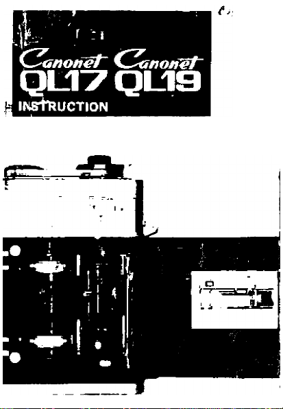
English Edition
Page 3
CANONET QL 17
The positions of the varicus parts for Canonet QL 17 and their
terminology are the same as for the Canonet QL 19 Refer to
the left hand page.
Page 4
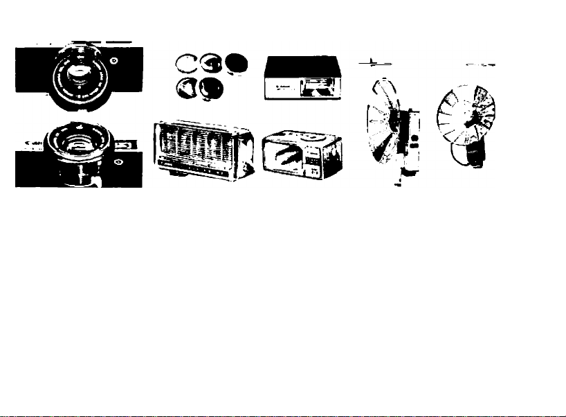
■ACCESSORIES FOR CANONET QL 17 AND CANONET QL 191
* Clamp-on Type Lens Hood
Necessary to shut out the harmful light
from outside the field of the picture. It
may be inversely put so that the lens
cap can be covered.
* Flash Unit V-3
Equipped with interchangeable three-way
type socket. Use of PH baseless adapter
possible. Highest quality type flash unit
with wide use for four kinds of flash
bulbs. Head is revolvable.
* Flash Unit J-2
I All-round type. The AG, and PH baseless
adapters may be used.
* Flash Unit J-3
For exclusive use with baseless bulbs. PH,
AG socket switching type.
* Flash Quint
Small type flash equipment which illumi
nates five bulbs in succession. Exclusive
AG type.
* 55mm Screw-In Type Filters
With plastic case. UV, Yi, Y3, Oi, Ri, Gi,
Skylight, Color Conversion A and B, ND4
and ND8.
* Canon Release
* Speedllte 100
Page 5
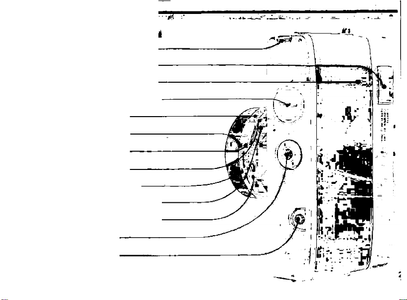
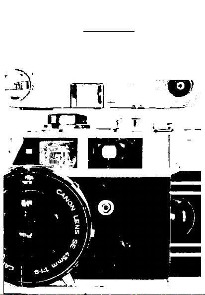
Back Cover LockFinder Eyepiece ■
Back Cover
Mercury Battery Compartment
Shutter Speed Ring
ASA Film Speed Index
DIN Film Spaed Index
Self-timer Lever
Film Speed Setting Lever
Focusing Lever
Simple Exposure Marks
Tripod Socket
Film Rewind Button
Page 6
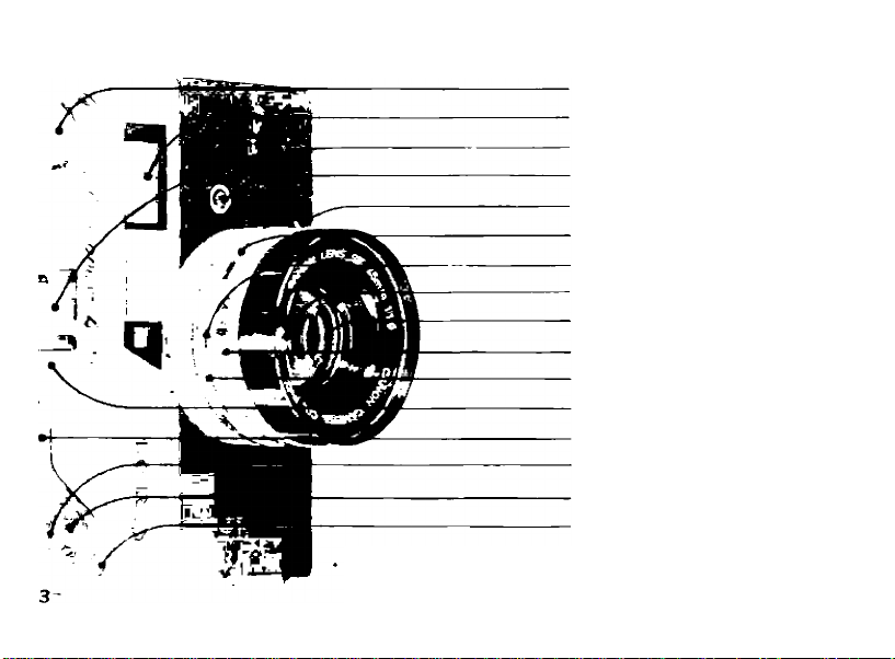
Film Rewind Crank
Range Viewfinder Window
Accessory Shoe
Flash Synchronization Socket
Safety Stopper Release Lever
Flash Setting Lever
Auto Mark
CdS Meter Window
Lens
Shutter Speed Ring
Aperture Scale Ring
Film Plane Mark
Film Advance Lever
Cable Release Socket
Shutter Release Button
Film Counter
Keep this page open while reading the instructions in the Manual.
This will permit the position of each designation to be seen at a
glance. On the Fast page there is a photograph as seen from the
opposite side
Page 7

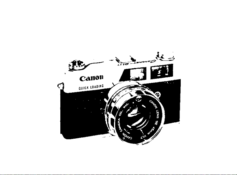
FEATURES OF CANONE! QL 17 & CANONE! QL 191
Canone! 17 and Canone! 19 are EE cameras !ha! have cap!ured !he mas! camera fans in !hi
world. They have trough! !he grealesi sa!isfac!ion !o !he larges! number of camera fans due w
!heir superior mechanism. Wi!h ihe in!roduc!ion of Canon's revoluiionary and unique QL film load
ing device imo !he laies! Canone! L 17 and Canone! QL 19, ihe iroublesome task has been compleicly eliminaied. This new QL system, which was developed by Canon ahead of other camera mahers, will be enthusiastically received as was the EE mechanism.
4.
New film loading with OL device
1.
Just place the film in the prescribed place
and the "magic ciaw” of the QL device
accurately leads the film for correct load
ing. It is a revoiutionary mechanism,
developed by v/orld-famous Canon, that
uses ordinary 35mm fiim in cartridge
sold in any camera shop.
The fast Canon Lens FI.7 is the bright
2
.
est among the EE cameras. 6-element,
5-component construction inciuding its
three new type giasses, enables sharp pic
tures to be taken. The lens is also parti
cularly well-suited for color photography.
3. Highly sensitive CdS exposure meter
The built-in CdS exposure meter, with
a wide photometric scope and high pre
cision, always guarantees a proper amount
of exposure.
Operating aperture manually for ordi
nary photography
In case of flash photography as well as!
photography for a specific purpose, th^
extent of the aperture may be regulated
manually.
5.
Finder with multi-layered film coat
ing multi-layered coating have been ap
plied to the half-transparent mirror inside
the finder to increase the transparency
factor, and to make clearer the
rangefinder.
Other features
Both the lens and exposure meter are
covered with one filter. There is no need
for adjusting the exposure even when us
ing a filter. Comes complete with various
safety devices for preventing misuse.
2
Page 8

MAIN SPECIFICATIONS FOR CANONET QL 17 & CANONET QL 19
Type :
Film size :
Lens :
Shutter :
Exposure Meter :
EE Mechanism :
Operating Range of Meter
Film Speed Index :
Finder:
Flash Synchronization :
Film Loading :
Film Winding :
Film Counter :
Film Rewind :
Size ;
Weight:
35mm Lens Shutter Type EE camera.
24mm x 36mm.
Canonet QL 17
Canonet QL 19
B 1 ','2 ','4 ''a '/15 '/30 '/'60 '/'125 '/'250 '/'500
Built-in self-timer.
Highly sensitive CdS exposure meter,
used as power source
Fully coupled with exposure meter, shutter and lens aper
ture. Shutter priority type EE. Manual aperture setting
possible.
EV2.5-19.
ASA 25-800.
Double-image superimposing system, coupled rangefinder
Marked finder with parallax error automatically corrected
Magnification ratio 0 7X. Visible aperture readings and
warning marks in the viewfinder.
MX flash synchronization. Speedlight, M class and F class
of flash bulbs can be synchronized.
Revolutionary film loading with Canon's unique QL device
using film in cartridge
Single operation 120° winding lever type.
Self-resetting type.
Press rewind button and rewind with crank.
140 X 79 X 31mm (lens protruded QL 17, 37mm; QL 19,
33mm).
Canonet QL 17 830 grams
Canonet QL 19 800 grams
Canon Lens SE 45mm F 1.7 6-element
5-component construction.
Canon Lens SE 45mm F 1.9 5-element
4-component construction.
Mercury battery
Page 9
PRECAUTIONS FOR HANDLING CANONET QL 17 AND CANONET QL 19
Please read the following instructions
carefully in order to avoid damaging any
of the mechanism or causing incorrect
exposures.
1. Do not turn the shutter ring or the aper
ture ring while pressing down on the
shutter button.
2. The shutter ring is equipped with a safety
stopper device.
When the stopper catches, do not turn
g the shutter ring any more. (See page H i
3 When the back cover of the camera is
opened, the inner cover —i.e. QL coveropens simultaneously. Do not touch the
QL cover when opening and closing. It is
preferable not to touch the entire QL
mechanism unless necessary.
4. When loading film, be sure that the tip
of the film comes to the red mark (•).
5. Do not use the intermediate space bet
ween the shutter speed index.
6 Always charge the self-timer after set
ting the flash setting lever to X.
Page 10
I
MERCURY BATTERY LOADINGl
Load the mercury battery in a separate
envelope into the battery compartment.
Since the mercury battery powers the CdS
meter, unless the battery is in position the
meter will not function.
1 Insert coin into groove of battery cover
and turn to the left to remove.
2. Face the central contact of the mercury
battery inwards and insert, then screw
the cover back in.
When inserting, do not confuse the 0 0.
In case of reverse insertion, the meter will
not function properly.
* For mercury battery, the National M-IP
Page 11

c
€>
model or the Toshiba TH MP is used—
equivalent to the United States Mallory
RM-IR. Life of the battery in continuous
use is about two years.
Do not soil with perspiration or finger
prints.
Before insertion, clean mercury battery
thoroughly with dry cloth. Perspiration
or finger marks may cause corrosion.
Be careful not to insert unclean battery
as it may damage the camera contact
point.
When not in use for a long period, remove
the mercury battery and keep in a dry
place.
Page 12
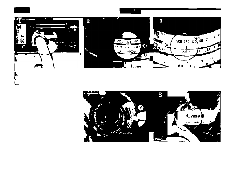
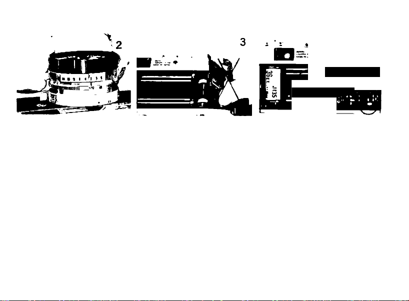
STEPS IN EE PHOTOGRAPHY
The film is loaded with 2, Set the film speed
the unique QL mechanism.
7. Focus and compose the 8. Press the shutter release
picture. button gently.
3. Set the aperture ring to
AUTO mark.
Page 13

4. Adjust the film speed setting
lever to a simple exposure
mark by turning the shutter
speed ring.
finder for QL 19. In the case of
Canonet QL 17, the aperture stop
on the right end starts from 1.7.
5. Remove the lens cap.
(1) Needle indicates lens aperture:
Gives correct exposure.
(2) Needle inside the arrow mark:
Turn the shutter ring in the direction
of the arrow and take the picture.
(3) Although the ring is turned, the needle
will not indicate the aperture:
Indicating no picture can be taken. In
other words, functioning of EE photo
graphy is not possible.
6 . Wind the film advance lever.
Page 14

IPREPARATIONS FOR EE PHOTOGRAPHY
ling dow»^« fil
Before using the EE mechanism for taking
pictures, prepare the camera so that the
following three conditions are fulfilled :
Adjust the AUTO mark of the aper
1
ture ring to the indicator.
Press and turn the film speed setting
2
lever, adjusting it to the speed index
of the loaded film.
* Film speed index is indicated on the film
box.
* When setting the film speed lever, it is
essential that the shutter speed should
10 be set at a high speed of over 1/15 sec.
r
.•lOO* * -50; ••100--50-
•- 21 ■ -IBfflZl
Indoor cloudy Sunny
••“•IB*
-X>i- 1
-- c
* The click stop functions for the following
16 indicated film speeds:
(32)(<I0) (6-()(80) (125)(I60) (250)(320) (500)(640) '
ASA 25 ■ • 50 • • 100 • • 200 • • 400 • • 800
DIN 15- -18 • • 21 • • 24- • 27- • 30
(16)(I7) (I9)(20) (22)(23) (25)(26) (26)(29)
* In case of using a high speed film, if it is
under 1/15 sec., the Under & Over Expo
sure Lock will catch, making setting
impossible.
Turn the entire shutter ring, and adjust
3 the index position of the film speed
setting lever to the simple exposure
mark of either sunny, cloudy or indoors.
Page 15

* When adjusting the simple exposure mark,
always make the adjustment by turning
the entire shutter ring. The setting may
be approximate. Set at a position where
the shutter ring catches the click stop.
Safety device against incorrect exposure
* To avoid setting the exposure conditions
beyond the working range of the EE,
the Under & Over Exposure Lock device
has been incorporated into the shutter
ring. When the shutter ring stops, do not
unduly try to make the rotation.
The Under & Over Exposure Lock catches
at the following positions:
Under ASA 80 1 sec.
For ASA 100 V2 sec.
For ASA 200 1/4 sec.
For ASA 400 '/9 sec.
For ASA 800 Vis sec.
When wishing to click the shutter at a
slower speed, beyond the limit of the
Under & Over Exposure Lock device, the
lock may be freed by turning the shutter
ring while pressing the Under & Over Ex
posure Lock release lever. In this case, as
the EE mechanism will not function, release
AUTO and set the lens aperture manually.
Page 16

Do not uce B exposure for EE photo
graphy
As it is meaningless to use the B exposure
for EE photography, it should not be used.
Accordingly, the Under & Over Exposure
Lock works for the B index. (See page 20
for setting.)
* Do not use the intermediate space of the
shutter speed index.
11
Page 17

HHOLDING THE CAMERA
12
Page 18

►
Holding the camera firmly
is very important if you
want to take a clearly
focused picture. Hold the
camera in either a vertical
or horizontal position, as
shown in the photographs
Look through the finder,
and adjust the focus while
determining the composi
tion. Then, gently press
the shutter button,
1. Hold the camera with
both hands as firmly as
possible,
2. Stabilize the camera by
pressing it against the
cheek or forehead.
3. When the camera is in
a horizontal position, both
elbows should be firmly
against the body, and at
least one elbow should be
resting against the body
when in a vertical position.
Page 19

Page 20

/ i:
/
13
Page 21

IPREPARATIONS FOR EE PHOTOGRAPHY
1 Wind the film advance lever.
By winding the lever, a single frame
of film is advanced, charging the shut
ter. At the same time, the film counter
advances by one number.
2 Focus looking through the
viewfinder.
When the focusing lever is moved,
correct focus is achieved when the two
images seen in the center of the viewfinder
14coincide completely.
3 Determine the composition to be
recorded within the frame.
The field-of-view which will appear on
the film can be seen within the rectangu
lar frame. The frame is coupled to the
rangefinder, and as the parallax error is
automatically corrected, the range which is
in view will appear on the film in its entirety.
4 Press the shutter button while
looking through the viewfinder.
When the needle is pointing to the
aperture stop the shutter may be clicked.
It is important to press the shutter button
gently in order to avoid blurry pictures.
Page 22

■ Do not press the shutter button indiscrim
inately
>■ When the shutter actuates, the film ad
vance lever is again ready to advance.
In case the exposure is incorrect for EE pho
tography, the safety device will prevent the
pressed shutter button from being re
leased. In this case, the needle inside the
viewfinder will be within the arrow mark.
Turn the shutter ring in the direction of the
arrow so as to bring the needle within the
range of the aperture stops.
Page 23

Distance scale
Although for ordinary picture-taking the dis
tance scale is unnecessary, it indicates the
distance between the subject in focus and
the film surface. It is
possible to get the
photographic distance
uc
Indicator
^/l^ance scale
lane mark
I
by adjusting the dista
-nee scale to the indie
-ator.
J
15
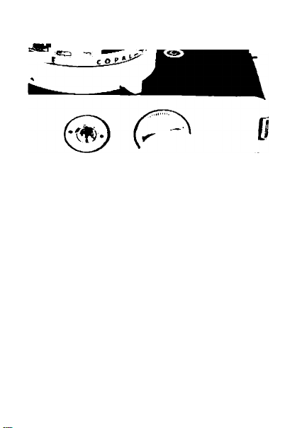
Page 24

I EE PHOTOGRAPHY INDICATOR AND CHANGE IN SHUTTER SPEED I
Look at the marks and figures within the
viewfinder. The arrow marks to the left
and right indicate the change in shutter
speed, and the aperture readings the cor
rect exposure section.
The needle shows the aperture
reading.
The needle is not within the correct
exposure section.
Picture can be taken if the
shutter speed is changed.
Picture cannot be taken even .
though the shutter speed is
altered
16
4
f-
me
Shutter may be clicked at correct exposure.
When the needle is within the arrow mark
pointing to the left, turn the shutter ring to
the left.____________________________________________
When the needle is within the arrow mark
pointing to the right, turn the shutter ring to
the right.
__________________________________________
If the needle does not advance to the correct
exposure section, the picture cannot be taken,
(beyond the range of the exposure meter).
When turning the shutter ring (or aperture
ring), remove the finger from the shutter
button.
16 V9
Scope of correct
exposure
-1
]
Page 25

When the camera is directed towards the
subject, the needle will swing according
to the strength of light, indicating the
conditions for ohotographing
For obtaining the proper exposure, make
adjustments according to the diagrams be
low before taking the picture
Under exposure
Over exposure
When the stopper catches, do not turn the shut
ter ring further, (see page 11
When the needle does not point to the correct
m
Page 26

exposure, although the shutter ring is fully
turned, it indicates that the subject is either
too bright or too dark, beyond the limits of the
exposure meter Taking of pictures under such
a condition is not recommended.
As the shutter ring has two arrow marks, turn
the shutter ring so that adjustment can be
made in the direction of the arrow where the
needle of the viewfinder stays.
When the aperture is switched to the manual
aperture setting, the needle will stay to the
right corner
The intermediate points of the aperture stops
show F2 8, 11 from the right
If the film advance lever is not fully wound,
the shutter will not click although the shutter
button is pressed.
When the background is excessively bright
compared to the main subject, or in case taking
pictures against the light, there is always the
possibility that the main subject is under
exposed Picture may be taken by lowering
the film speed index by one stop.
For instance, by setting the film speed at ASA
50 in case the ASA is 100 This procedure
should be regarded as an exception, as soon
as the picture is taken the film speed Index
should be returned to its original position In
case even this step is not applicable, switch
the aperture setting to manual. 17
Page 27

I SELF-TIMER I
' L
•
1^
When the self-timer is used, the shutter
will be actuated about ten seconds after
the shutter button has been pressed. Follow
the instructions below :
1 Turn the flash setting lever to X.
Set the self-timer lever by turning it in
2
the direction of the arrow and then
wind the film advance lever.
2 Press the shutter button sufficiently
18 downwards.
■ iVl
Page 28

Setf-tfmér lever
Do not move the self-timer lever without
turning the flash setting lever to X.
Press the shutter button from the back
of the camera.
If you press the shutter button, standing
in front of the camera, the exposure will
be affected by the shade and you cannot
get the properly exposed main subject.
In case the self-timer is utilized, use the
shutter with speed of slower than 1 '30
sec. for M type bulb photography.
The self-timer may be used for manually
operated aperture.
Page 29

MANUALLY OPERATED APERTURE
When the AUTO mark of the Canonet QL
has been removed, the automatic mecha
nism ceases to function It is then possible
to manually operate the aperture and shut
ter speed separately Accordingly, when
the effective use of the shutter speed or
aperture is desired, or in case it is essential
to expose the dark subject for a long time,
as well as to regulate the aperture for flash
photography, the manual mechanism should
be employed Everything else is operated
as usual.
The aperture regulates the amount of light.
As the numerical value increases, it gets
darker. For each stop of the index, the
light decreases by one-half. Thus, when the
index is lowered by one stop the exposure
time must increase two times, two stops
by four times The ratio between the aper-
Page 30

PHOTOGRAPHY!
ture stop and the amount of exposure, with
F2 as the basis is as follows :
Aperture stop: 1.7 2 2.8 4 5 6 8 11 16
Exposure ratio: '/1.38 1 2 4 8 16 32 64
Effectiveness of the aperture
* As the numerical value increases, quantity
of light becomes lesser. For each indexed
point, the light is reduced one-half.
* The bigger the numerical value, the deep
er the scope of the focusing.
“ The farther the distance of the subject,
the deeper is the scope of focusing.
* On the other hand, the greater the lens
opening, the shallower the focus.
The shutter speed adjusts the exposure
time Similar to the lens aperture scale,
each index of the shutter speed means
double or one-half of the exposure time.
So, if you turn the shutter speed ring one
stop faster, open the lens aperture one stop
Effectiveness of shutter spee9
High speed; For preventing blurs, taking
a fast moving object, and for effective
ness of use of aperture.
Low speed; For taking dark subjects,
using blurs for effects, and for effectiveness
of use of deep aperture 19
Page 31

IB (BULB) exposure!
________
B stands for bulb exposure Since the shut
ter remains open as long as the shutter
button is being pressed, it is used for long
exposures exceeding 1 sec.
1 The aperture ring is released from AUTO
2 Keep the safety stopper release lever in
3 Turn the shutter speed ring and match B
4 Wind the film advance lever and press
20 shutter open is being pressed.
»V
and set a desired aperture stop.
pressed state
to the indicator.
the shutter button. The B exposure works
while the shutter button which keeps the
Page 32

■ Unless the safety stopper release lever is
pressed, B index cannot be set to the
indicator.
■ The safety stopper works for the safety
device of the EE mechanism. When the
shutter ring is turned from B, the safety
stopper release lever will get ejected and
return to its original position.
T exposure
When exposure is being made over an ex
tended period, make the setting at B expo
sure as explained above. Open the shutter
with a lock attached release and lock the
release during exposure.
Page 33

IFLASH SYNCHRONIZATION!
Attach the flash unit to the accessory
shoe, and insert the cord into the
flash synchronization socket of the
camera.
For flash bulbs, the M or F classes of
bulbs or speedlight may be used.
According to the type used, the flash
setting lever must be set at either M or X.
In case of flash photography, the aper
ture is determined by the guide
number. Accordingly, the aperture
ring must be removed from AUTO. (EE
photography cannot be taken.)
Page 34

Flash Synchronization Table
Type
M class j M |AII shutter speeds
F class ; X ¡Slow speed under 1/60 sec.
Speedlight , X All shutter speeds
poi'n\^'^*l Synclironization
21
Page 35

FILM LOADING — QL LOADING METHODI
•
I Film rewind crank
> Cartridge holder
I Explanatory diagram for loading
QL shaft
• QL cover
• Film set mark
• Sprocket window
• Sprocket
• Film Used
All ordinary 35mm film in cartridge can be
used for the QL film loading device. No spe
cial or exclusive type film Is necessary.
• Handling
When loading, avoid direct sunlight. When
unavoidable, face back to the sun and load
quickly.
Page 36

1 Open the back cover.
Pull the back cover lock and the back
will rise Next, open the back cover to
maximum. When the back cover is opened,
the QL cover also opens simultaneously and
is ready for loading the film.
* The QL cover performs a very Im
portant function in film loading.
This cover automatically opens and
closes together with the opening
and closing of the back cover. Do
not touch the QL cover,
2 Insert cartridge.
Raise the rewinding knob sufficiently
After the cartridge has been inserted,
push the knob back to its former position,
and then put the fork into the axis of the
cartridge In case the knob does not fully
return, it can be easily put into proper
position by turning it slightly to the left or
right
3 Pull film to red mark.
4 Engage the film perforations with
the gear.
When doing this, face the cartridge
as shown in the picture and hold the film
down with the left hand so that it does not
rise.
23
Page 37

5 When the back cover is half-closed,
the QL cover presses down on the film.
Check through the sprocket window
whether the 'ilm has been engaged cor
rectly onto the gear.
6 Close the back cover.
Merely press the cover and it will be
firmly locked.
* If the film is sagging, the cartridge will rise
24
and the back cover will not close.
*
7 Make two unexposed shots.
Remove the aperture ring from AUTO,
and with lens cap still on, wind the
film advance lever, releasing the shutter
twice. The film counter will advance to 0.
With the next advance, the camera is ready
for the first shot.
* The condition of film feeding can be check
ed by watching the turning of the rewind
knob when the film advance lever is
wound. If the film sags, remove the sag
ging by turning the rewinding crank.
8 Return the aperture ring to AUTO,
Page 38

■FILM REWINDING!
<2
k ■—
t
- 2l_
Since no further winding is possibie when
the end of the fiim is reached, rewind the
fiim into the original cartridge, as explained
below. As the exposed film is naked within
the camera, the entire roll will be ruined if
the cover is opened before rewinding.
1 Press in the rewind button.
2 Rewind with crank
* If the exposed film, including the leader
part, is rewound completely into the car
tridge, there is fear of light leakage into
the cartridge when it is taken out of the
camera. When rewinding has been com
pleted, the rewind button stops revolving
and the resistance on the rewinding crank
Page 39

becomes sligitly lighter. This means that
all the film hs been rewound except for
the leader prt. Stop rewinding at this
stage,
3 Open th back cover.
4 Removethe cartridge.
Remove fter raising the rewinding
knob comjetely.
' Once the rewincbutton has been pressed, the
finger may be amoved. When the lever is
wound, this buttn will return automatically.
■ If winding confines even after the film is at
an end, the flinn vill tear and rewinding wilt
become innpossita. Please be very careful. If
this happens, op* the back cover in a dark
room.
25
Page 40

CANON CAMERA CO., (NC.
3Í2; Shimo maruko cbo, Oht. ku, Tokyo, Japan
CANON U S. BRANCH
554 Fifth Avenue, New Yorl, N V,10036,
U.S.A.
CANON S.A. GENEVE
1 Rúe de Hesse, Geneva, Ssitzerland
CANON LATIN AMERICA ^ \
Apartado 7022, Via España ¿0, Panama
R.P.
________
f
PUB- NO. 5213A
PRINTED IN JAPAN
 Loading...