

CANONET G-III 17
Similar models: Canonet QL 17/19
Battery: 1 ea. PX13
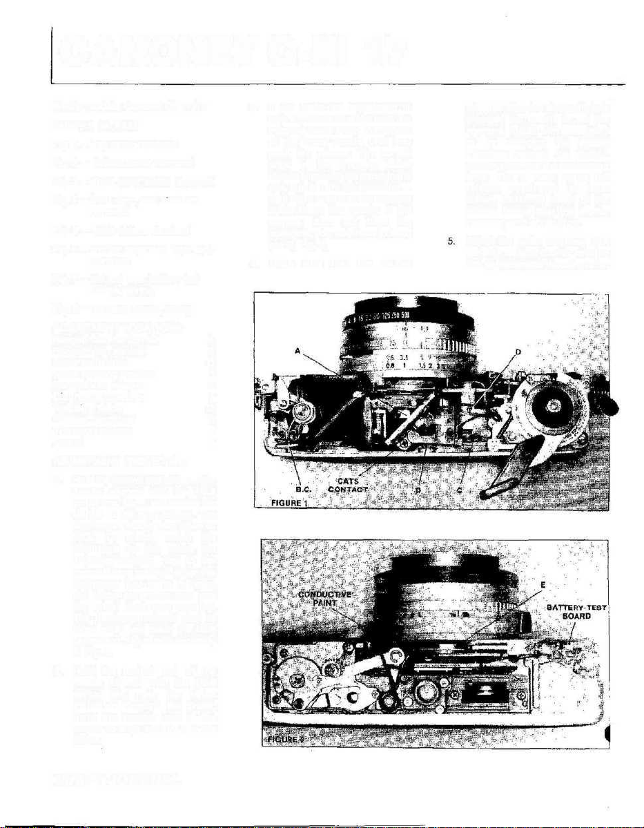
Fig. 1 — top cover removed
Fig, 2 — bottom cover removed
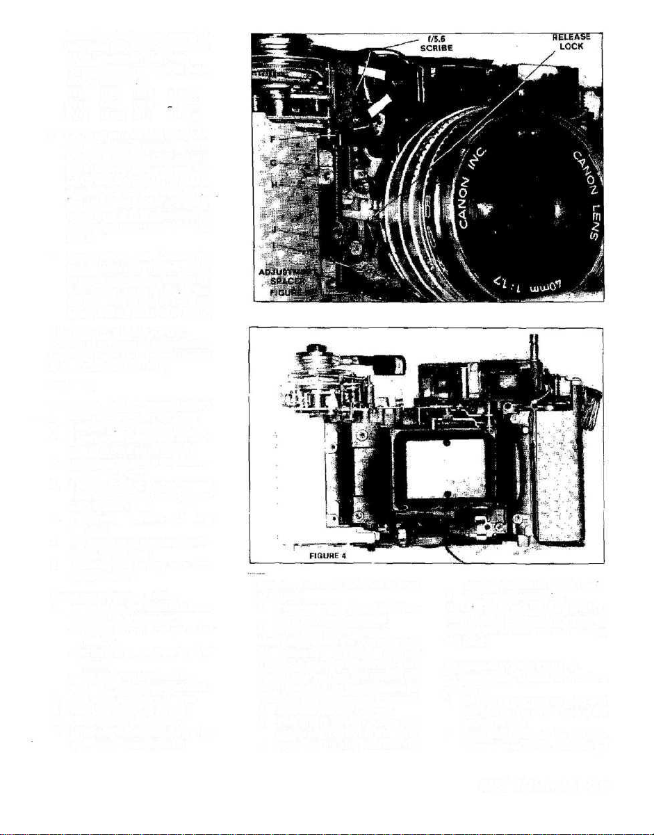
Fig. 3 — front cover plates removed
Fig. 4 — front view, lens standard
removed
Fig. 5 — back of lens standard
Fig. 6 — shutter separated from lens
standard
Fig. 7 — old and new battery-test
boards, wiring
Fig. 8 — terminal board, wiring
ADJUSTMENT LOCATIONS:
Rangefinder, horizontal A
Rangefinder, vertical B
Meter calibration C
Meter housing position D
Rangefinder resistor E
Diaphragm opening F
Trapping blade Q
Release over travel H
Transport release I
Focus J
ADJUSTMENT PROCEDURE:
1. Hold the control end of the meter
needle aligned with the f/5.6
scribe line, Fig. 3. and release the
shutter at the auto setting. The
diaphragm should stop down to
f/5.6. To check, watch the
diaphragm as you rotate the
diaphragm-setting ring to the
manual f/stop settings. When the
diaphragm just starts to open,
the f/stop calibration tells you
the actual diaphragm opening.
The diaphragm should start to
move when you reach the f/5.6
calibration. Adjust with eccentric
F, Fig. 3.
2. Hold the control end of the
needle aligned with the f/5.6
scribe and note the f/stop
indication through the finder.
Bend the readout end of the
needle to align with f/5.6 in the
finder.
3. If you make the adjustment in
step #1, check to make sure the
trapping blade is not in the path
of the meter needle until you
push the release. The curved
edge of the trapping blade
should align with the curve in the
slot, Fig. 3. Turn the eccentric —
G in Fig. 3 —so that the trapping
blade clears the needle. If the
camera does not have the
eccentric, you may have to bend
pin G, Fig. 4.
4. Make sure that the shutter
releases after the stepped blade
engages the needle to set the
aperture. Adjust with eccentric I
or by changing the spacer
thickness between the shutterrelease plate and the connecting
lever, Fig. 3. Also adjust the
release over travel (at least
0,4mm additional travel of the
release button after the shutter
releases) with eccentric I.
Adjust the meter accuracy with
variable resistor C or by rotating
the galvanometer housing after
18/SPT JOURNAL
loosening the locking screw. If
you rotate the housing, check the
CATS adjustment (step #6).
Proper needle readings at ASA
100. K-factor 17 5:
EV8 1/30 f/2.8 ±1 stop
EV11 1/60 f/5.6 +1 stop
EV14 1/125 f/11 +-1 Stop
6. CATS adjustment. Set auto, ASA
100, and the 2-meter focus
position. Cover the CdS ceil and
short between ground and the
CATS contact, Fig. 1. The needle
should indicate between f/5 6
and f/8. If not, rotate the meter
housing or shift the position of
the rangefinder-resistor band,
Fig. 2.
7. Focus adjustment. Loosen the
three setscrews on the outer
circumference of the focus ring.
Also loosen screw J, Fig 3. Set
the focus ring to infinity and slide
screw J for the best infinity focus.
DISASSEMBLY HIGHLIGHTS:
Position of left-hand threads: shutterretaining ring in G-lll (normal thread
in Now Canonet QL 17/19)
Sequence:
1. top and bottom cavers (battery
cover and cover spring loose)
2. 2 sections, front leatherette
3. 2 front-cover plates, one on each
side of lens (2 screws each)
4. unsolder red wire from batterytest board, Fig. 7
5. 2 screws holding shutter-release
plate to connecting lever (adjust-
ment spacer loose)
6. 4 screws, corners of lens
standard
7. lift aside lens standard (view-
finder mask loose)
8. unsolder blue battery wire from
terminal board
Sequence to remove shutter:
1. unsolder the five wires that come
through the shutter port:
—yellow from rangefinder
resistor
—white and purple from terminal
board
—red from variable resistor
—black from hot-shoe contact
2. free wires from wire clamps
3. rear light shield (2 screws)
4. unscrew rear lens group
5. unscrew shutter-retaining ring
(left-hand thread in G-lll)
Sequence to reach switches at front
of shutter:
1. front-retaining ring, identification ring, photocell mask
2. unscrew front lens group
Note: Unscrewing the complete lens
cell requires a special spanner
T0630-13-9246-1T. Without the
special tool, you can first remove the
front element. It's then possible to
reach the spanner notches in the cell.
3. 2 screws holding CdS cell
4. filter ring (3screws) — pass CdS
cell through cutout in filter ring
5. speed-setting ring (tab on ring
passes into slot in speed cam)
6. film-speed setting ring
Note. To reach the shutter
mechanism, disassemble from the
back of the shutter rather than from
the front.
REASSEMBLY HIGHLIGHTS:
To mount the shutter to the lens
standard:
1. Seat the intermediate ring and
the charge ring on the back of the
shutter, Fig. 6.
2. Push the end of the shutterrelease lever as far as it will go
SPT JOURNAL/19

toward the lens opening.
3. Seat the lens standard over the
shutter, making sure that the tab
on the charge ring passes
through the slot in the shuttercharge lever and that the
aperture-connecting pin passes
above the aperture-connecting
lever.
METER TESTS:
1. Check the CdS cell between the
yellow wire connected to the
rangefinder resistor and ground.
2. Check the galvanometer between the red wire at the variable
resistor and the blue wire at the
terminal board. Approximate coil
resistance: 1.6K.
3. At the auto setting, the needle
deflection should change as you
change the film-speed setting,
shutter-speed setting, and light
level. No deflection — check the
CdS cell, the galvanometer, the
battery connections, and the
brush contacts at the front of the
shutter.
4. At the guide-number settings,
the needle deflection should
change as you change the focus
setting and the light level. No
change at the different focus
settings — check the rangefinder
resistor and the switch at the
front of the shutter. Check the
switch between the white lead
from the rangefinder resistor and
ground: you should measure
direct continuity at the guidenumber settings and no
continuity at auto.
5. The meter should turn off at the
manual f/stop setting (switch at
front of shutter).
6. At auto, the lock on the release
plate, Fig. 3, should prevent the
shutter from releasing if the
needle is in one of the red areas
at either end of the viewfinder
scale (underexposure or overexposure). The shutter should
always release at the manual
I/stop settings.
BATTERY-CHECKER TESTS:
1. The battery-test lamp should
turn on when you short B.C., Fig.
2, to ground.
2. The battery-test lamp should
turn on with 1V connected
directly between its leads.
3. If the battery-test lamp does not
turn on with a good battery,
check the voltage at the
transistor base, Fig. 7. If you
measure the proper base bias
(D.8V), the transistor is the
problem. If you do not measure
the base bias, there's an open in
the bias path (one of the resistors
on the underside of the batterytest board or the thermistor).
OTHER COMMENTS;
1. You can reach the rangefincder
adjustments without removing
the top cover. Slide off the
accessory-shoe cover to reach
the horizontal adjustment:
unscrew the cover screw at the
back of the top cover to reach the
vertical adjustments.
The rangefinder resistor comes
in two parts —• the carbon
resistor and a contact strip, Fig.
2. If you replace either part, apply
conductive paint such as Silver
Print between the contact strip
and the resistance bend as
shown in Fig. 2.
20/SPT JOURNAL

BLACK (LAMP)
BLACK (LAMP)
PINK (SWITCH)
B
TR
RED (-BATTERY)
BLACK (LAMP)
BLACK (LAMP)
B
TR
RED (-BATTERY)
FIGURE 7
OLD
PINK (SWITCH)
NEW
FIGURE 8
SPT JOURNAL/21
 Loading...