

Page 1

MultiPASS C5000
SERVICE
MANUAL
Canon
Page 2

Application
This manual has been issued by Canon Inc. for qualified persons to learn technical theory, installation,
maintenance, and repair of products. This manual covers all localities where the products we sold. For this
reason, there may be information in this manual that does not apply to your locality.
Corrections
This manual may contain technical inaccuracies or typographical errors due to improvements or changes in
products. When changes occur in applicable products or in the content of this manual, Canon will release
technical information as the need arises. In the event of major
long or short period, Canon will issue a new editions of this manual.
changes
in the contents of this manual
over a
The following paragraph does not apply to any countries where such provisions are
inconsistent with local law.
Trademarks
The product
individual companies.
names
and company names described in this manual are the registered trademarks of the
Copyright
This manual is copyrighted with all rights reserved. Under the copyright laws, this manual may not be
copied, reproduced or translated into another language, in whole or in part, without the written consent of
Canon Inc..
Copyright 0 1997 by Canon Inc.
CANON INC.
Office Imaging Products Technical Support Dept. 2
5-1
Hakusan
DTP System
This
mnnunl
SUPER LASER SHOT
All graphics
All
documrwts
7-Chome,
was
were
and all page layouts
Toridecity, lbaraki 302, Japan
produced
produced with Macromedia FreeHand’.
on an Apple Macintosh” personal computer, final pages wer” printed on Canon
R406
PS.
were
created with
&arkXPress”.
Page 3
The marks used in this manual have the following meanings
Meaning
States a precaution to be taken to prevent danger to personnel, damage to
the product, or damage to electronic components by discharge of static
electricity. for example.
A
States a precaution to be taken to prevent damage to electronic components
by electrostatic discharge.
A
Informs you of fire-related cautions.
63
e
NOTE
REFERENCE
Informs you that the plug must be
starting an operation.
Gives useful information to understand descriptions.
Indicates sections to be read to obtain
removed
mere
from the power outlet before
detailed information.
I
Page 4
This manual is divided into
five
parts, and contains information required for servicing the
product.
Part
1: Facsimile
This section describes the facsimile function of the respective product.
Part 2: Printer
This section describes the printer function of the respective product.
Each of the above parts is further divided into the following four chapters:
Chapter 1: General Description
This part explains product specifications and the how to service the unit safely. It is very
important, so please read it.
Chapter 2: Technical Reference
This part explains the technical theory of the product
Chapter 3: Maintenance and Service
This part explains how to maintain the products for adjustment and troubleshooting and
service operations and service switches.
Chapter 4: Appendix
This part
explains
the informations of the optional products and user data flow.
z :
: -
0
REFERENCE
l
:
For more details of
of USER’S
l
Procedure for assembly/disassembly and greasing points are not given in this
GUIDE.
manual. See the illustrations in the separate volume of
l
Detailed description of each
except the new
See G3
Facsimile Service Data Handbook (supplied separately)
user
operations and
SSSW/parameter
SSSWslparameters
user
reports, see the separate volume
is not given in this manual
added to this model.
PARTS CATALOG.
for details
them.
l
See the G3 Facsimile Error
the error codes not shown in this
l
Detailed description of connector Locations and Signal Descriptions in not
Code
L~sf
(Rev. 1, supplied separate/y)
mnnual.
for details of
given in this manual.
See the Circuit
Diagram
for details
them.
II
Page 5

REVISION
I
CONTENT
0
I
Original
Page 6

fart 1: Facsimile
Page
1- 1
1- 1
l-2
l-2
1-2
l-3
l-5
l-7
l-6
1 -11
1 -11
1 -14
1
-16
1 -18
1 -20
1 -22
1 -23
1 -23
1
-25
1 -25
1 -26
1 -26
1 -26
1 -27
1 -27
1 -32
1 -40
1 -42
1 -42
1
-42
1 -43
1 -45
1 -45
1 -46
1 -47
1
-46
1 -49
1 -50
1 -52
Chapter 1: General Description
FEATURES
1.
1 .I Overview
SPECIFICATIONS
2.
General Specification
2.1
Communication Specification
2.2
Scanner Specification
2.3
2.4
Copy Specification
2.5
2.6 Function
OVERVIEW
3
3.1 External View
3.2 Operation Panel
3.3 Consumables
4
DIMENSIONS
SAFETY & PRECAUTIONS
5
5.1
5.2
5.3
5.4 Data-related precautions
Printer Specification
3.3.1
BJ cartridge and ink cartridge and BJ cartridge container
3.3.2 Print media
Personnel Hazards
5.1 .I Electrical shock
5.1.2 High-temperature parts
5.1.3 Fire hazards
5.1.4 Moving pads
5.1.5 Preventing ink stains
General Cautions
5.2.1 Unit cautions
5.2.2 BJ cartridge cautions
5.2.3 Ink cartridge cautions
Servicing Cautions
5.3.1 Damage from static charge
5.3.2 Scanner unit
5.3.3 Print assembly
5.3.4 Paper feed section
5.3.5 Control boards
5.3.6 Opening the upper Cover
5.4.1
Data in the image storage memory (DRAM)
5.4.2 Data in the control processing memory (SRAM)
5.4.3 Data in the EEPROM
5.4 4 SCNT board replacement precautions
IV
Page 7

1 -53
1
-54
1
-54
1 -54
1 -55
1 -55
1
-56
1 -56
1 -57
6. QUALIFICATION REQUIRED FOR INSTALLATION WORK
5.4.5 Data initialization through service operation
Protective Mechanism
5.5
55.1 Data battery backup function
5.5.2 BJ cartridge maintenance features
5.53 Heat protection mechanism
5.5.4 Overcurrent protection
5.5.5 Lightning protection
5.56 Power leakage protection
Chapter 2: Technical Reference
COMPONENT LAYOUT
2-
1
2-
3
2-
6
2 -11
2 -18
2 -18
2 -21
2 -23
2 -25
2 -25
2 -26
2 -29
2 -32
2 -32
2 -32
2 -32
2 -33
2 -33
. .
2 -33
2 -34
2 -34
2 -34
2 -35
1.
SCANNER MECHANISM
2.
PAPER SUPPLY MECHANISM
3.
4.
PRINTER SECTION
5.
BJ CARTRIDGE
5.1 Structure
5.2 BJ Head Driver Block Diagram
5.3 Printing Signal
ELECTRIC CIRCUIT
6.
6.1 Component Block Diagram
6.2 Circuit Board Components
6.3 Flow of Image Signals
COMMUNICATION SYSTEM OPERATIONS
7.1 FAX/TEL Switching
7.1 .l Settings
7.1.2 Parameters
7.2 Answering Machine Connection
7.2.1
Settings
7.2.2 Parameters
NEW FUNCTION
8.1 Color Scanning Ability
8.1 .I Contact sensor specifications
8.1.2
Reading color documents
3-
1
3- 1
3- 1
3-
2
3-
2
3-
2
3-
3
Chapter 3: Maintenance & Service
1.
MAINTENANCE LIST
1.1
Consumables
Cleaning
1.2
Periodic Inspection
1.3
1.4
Periodic
1.5
Adjustment Items
1.6
General Tools
Replacement Parts
V
Page 8

3-
3
3-
4
3-
4
3-
4
3-
4
3-
4
3-
4
3-
4
3-
4
3-
6
3-
6
3-
7
3 -10
3 -14
3 -14
3 -15
3 -15
3 -19
3 -26
3 -26
3 -27
3 -29
3 -31
3 -31
3 -31
3 -31
3 -32
3 -33
3 -40
3 -41
3 -43
3 -43
3 -43
3 -44
3 -44
3 -45
3 -46
3 -46
3 -47
3 -49
3 -52
3 -57
3 -57
1.7 Special Tools
2. HOW TO CLEAN PARTS
2.1 Main Unit Outer Covers
2.2 Separation Roller
2.3 Document Feed/Eject Roller
2.4 Separation Guide
2.5 Scanning Glass (Contact Sensor)
2.6 White Sheet
2.7 Printer Platen
3.
ADJUSTMENT
3.1 CS LED Lights-on Duration Adjustment
3.2 Vertical Alignment Correction
3.3 Head Gap Adjustment
4.
TROUBLESHOOTING
4.1 Troubleshooting Index
4.2 Errors Shown on the Display
4.2.1 User error message
4.2.2 Error codes
4.3 Errors not Shown on the Display
4.3.1 General errors
4.3.2 Printing problem
4.3.3 Scanning problem
5.
SERVICE SWITCHES
5.1 Hardware Switches
5.2 Service Data Sening
5.2.1 Service data overview
5.22 Service data registration/setting method
5.2.3 Service data setting
5.2.4 Explanation of service data
5.2.5 New SSSWslparameters added to this model
6.
TEST FUNCTIONS
6.1
User Test Print Functions
6.1 .l Nozzle check
6.2 Service Test Functions
6.2.1 Test mode overview
6.2.2 Test mode flowchart
6.2.3 D-RAM tests
6.2.4 CS tests
6.2.5 PRINT test
6.2.6 Modem and NCU tests
6.2.7 Faculty tests
7.
SERVICE REPORT
7.1 Report Output Function
VI
Page 9

3 -57
3 -59
3 -67
3 -67
3
-66
4-
1
4-
1
4- 1
4-
2
4-
2
4-
3
4- 6
4 -10
7.1 .I
User report output functions
7.1.2 Service report output functions
6.
WIRING DIAGRAM
6.1 Wiring Diagram
8.2 Connector Name and Signal Descriptions
Chapter 4: Appendix
1.
INSTALLATION
1
.I Setting Up
1.2 Checking Operations
2. USER DATA FLOW
2.1
USER DATA FLOW (by Operation Panel)
2.2 USER DATA FLOW (by
2.3 SPECIAL MODE FLOW (by Operation Panel)
3. MAKER CODE
MultiPASS
Desktop Manager)
INDEX
VII
Page 10

Part 2: Printer
Chapter 1: General Description
I-
1
l-2
l-2
1- 5
1 -10
1 -10
1 -11
1 -12
1 -12
1 -12
1 -12
1 -12
1 -12
1 -13
1.
FEATURES
2.
SPECIFICATIONS
2.1 Basic Specifications
2.2 Interface Specifications
3.
OVERVIEW
3.1 Interface Connector
3.2 Printer Operation Panel
4. SAFETY & PRECAUTIONS
4.1 Personnel Hazards
4.2 General Cautions
5.
RESTRICTIONS
Chapter 2: Technical Reference
1,
2-
1
2-
1
2-
2
2-
3
2-
4
2-
5
2-
5
2-
7
2-
7
2-
7
2-
a
2-
a
2-
a
2-10
2 -10
2 -11
2 -11
2 -12
THEORY OF OPERATIONS
2.1 Outline
2.2 Mechanical Overview
2.3 Data Flow
2.4 Printing
2.5 Circuit Overview
2.6 720 dpi Printing/Smoothing
2.7 Printing Modes
2.6 Optimum Printing Direction Control
2.9 Ink Smear Control
2.10 Bi-Centronics Interface
4.2.1 Connecting the interface cable
4.2.2 Data lost when power cord is pulled out
4.2.3 Data reset
2.51
Printer circuit
Feature
2.6.1 Canon extension mode
2.6.2 Emulation mode
2.7.1 Printing mode
2.7.2 Photoprint mode
2.10.1 Functions
2.10.2Structure
Chapter 3: Maintenance & Service
1.
3-
1
3-
1
3-
1
3-
2
3-
2
MAINTENANCE LIST
2. HOW TO CLEAN PARTS
3.
ADJUSTMENT
4.
TROUBLESHOOTING
4.1
Errors Shown on the Display
VIII
Page 11

3-
2
3-
2
3-
3
3-
5
3-
5
3-
5
3-
5
3-
5
3-
6
3-
7
3-
7
3-
7
3-
4- 1
4-
4-
7
2
3
4.1 .I User error message
4.1.2
Error codes
4.2 Errors not Shown on the Display
5. SERVICE OPERATION FUNCTION
5.1 Report Output Function
5.2 Service Data
5.3 Test Functions
5.3.1 User test functions
5.3.2 Hexadecimal dump list
6. WIRING DIAGRAM
6.1 Wiring Diagram
6.2 Connector Location and Signal Description
6.2.1 SCNT board
Chapter 4: Appendix
1,
INSTALLATION
1.1
Choosing a Location for the Printer
1.2
Connecting the Printer to the Computer
IX
Page 12

.,,.
Part 1: Facsimile
Page
1-4
1- 6
1 -11
1 -12
1 -14
1 -15
1 -16
1 -17
1 -16
1 -19
1 -20
1 -21
1
-22
1 -23
1
-24
1 -38
1 -39
1 -40
1 -41
1
-43
1 -46
1
-47
1 -51
1
-53
Chapter I: General Description
Figure 1- 1
Figure l- 2
Figure l- 3
Figure l- 4
Figure l- 5
Figure l- 6
Figure l- 7
Figure I- 6
Figure I- 9
Figure
Figure
Figure l-12
Figure l-13
Figure I- 14
Figure l-15
Figure l-16
Figure
Figure
Figure l-19
Figure l-20
Figure
Figure l-22
Figure l-23
Figure 1-24
Scanning Range
Printing Range
External View
External View (2)
Operation Panel
Operation Panel (2)
Operation Panel (3)
Operation Panel (4)
Consumables
Consumables (2)
l-10
Print Media (1)
l-11
Print Media (2)
Dimensions
Personnel Hazards
Personnel Hazards (2)
Unpacking the BJ Cartridge
Ink Path Cartridge
l-17
Removing Cartridge Cap
l-16
Ink Outlet
Print Assembly Precautions
Opening the Upper Cover
l-21
Memory IC and Backed up Devices
Waste Ink Absorber
All Clear
(1)
(1)
(1)
(1)
2-
1
2-
2
2-
3
2-
6
2-
6
2-
9
2 -11
2-13
2 -13
2 -16
2 -19
2 -19
2 -20
Chapter 2:
Figure 2Figure 2- 2
Figure 2- 3
Figure 2- 4
Figure 2- 5
Figure 2- 6
Figure 2- 7
Figure 2Figure 2- 9
Figure 2Figure 2- 11
Figure 2- 12
Figure 2- 13
10
Technical Reference
Mechanical Layout
1
Electrical System Layout
Document Feed Section
Paper Feed Section
Paper Feed Motor Drive Switching
Paper Separation Mechanism
Printer Section
Purge Unit
6
Pump Operation State Detection
Ink Empty Detection
Nozzle Arrangement
Black BJ Cartridge Structure
Color BJ Cartridge Structure
X
Page 13
2 -20
2 -22
2 -22
2 -23
2 -24
2 -25
2 -29
2 -30
2 -31
2 -35
3-
5
3-
6
3-
7
3-
7
3-
6
3- 0
3-
9
3 -10
3 -11
3 -12
3 -13
3 -19
3 -27
3 -26
3 -32
3 -33
3 -34
3 -35
3 -37
3 -38
3 -39
3 -40
3 -40
3 -43
3 -45
3 -46
3 -47
3 -46
3 -51
3 -53
3 -55
Figure 2- 14 Photo BJ Cartridge Structure
Figure 2- 15 BJ Head Driver Block Diagram (Black BJ Cartridge)
Figure 2- 16 BJ Head Driver Block Diagram (Color BJ Cartridge)
Figure
Figure 2- 16 Printing Signals (HQ Mode)
Figure 2- 19 Block Diagram
Figure
Figure 2-21 G3 Reception Image Signal Flow
Figure 2-22 Color Copy Image Signal Flow
Figure 2-23 Contact Sensor
Z-17
Printing Sequence (Black BJ Cartridge/HQ Mode)
Z-20
G3 Transmission Image Signal Flow
Chapter 3: Maintenance & Service
Figure 3-
Figure 3- 2 CS LED Lights-on Duration Adjustment Operation
Figure 3-
Figure
Figure 3-
Figure 3- 6 Sample Test Pattern with Vertical Misalignment
Figure 3- 7 Vertical Line Misalignment Correction Procedure
Figure 3-6Headgap
Figure 3-9Adjustment Preparation
Figure3-10
Figure3-11
Figure3-12
Figure 3-13 Paper Feed Motor/Carriage Motor/Document Feed Motor Connector
Figure3-14
Figure3-15
Figure 3-16 Service Data (page 1)
Figure3-17
Figure
Figure3-19
Figure 3-20 Service Data (page 5)
Figure 3-21 Service Data (page 6)
Figure 3-22 Bit Switch Display
Figure 3-23 How to Read Bit Switch Tables
Figure 3-24 Nozzle Check Pattern
Figure 3-25 Test Mode
Figure 3-26 D-RAM Test
Figure 3-27 Print Test Pattern Check
Figure 3-26 Print Pattern Sample
Figure 3-29 CNG and DTMF Signal Reception Tests
Figure 3-30 Sensor Tests
Figure 3-31 Operation Panel
1
Cleaning Location
3
Printing the Test Pattern
3-4Test Pattern Sample
5
Correct Test Pattern
Head Gap Adjustment
Head Gap Adjustment (2)
Service Error Code Display
Defective Pattern (Sample)
Service Data Setting Method
Service Data (page 2)
3- 16
Service Data (page 3)
Service Data (page 4)
(1)
XI
Page 14
3 -58
3 -60
3 -61
3 -62
3 -64
3 -65
3 -66
3 -67
4-
2
4-
3
4-
4
4-
5
4-
6
4-
7
4-
8
4 -10
Figure 3-32 Memory Clear List
Figure 3-33 System Data List (page 1 - page 4)
Figure 3-34 System Data List (page 5 - page 6)
Figure 3-35 System Dump List (112)
Figure 3-36 System Dump List
Figure 3-37 Service Error TX Report
Figure 3-38 Service Error Activity Report (receiving)
Figure 3-39 Wiring Diagram
(2/2)
Chapter4:Appendix
Figure 4-1
Figure 4-2
Figure 4-3
Figure 4-4
Figure 4-5
Figure
Figure 4-7
Figure 4-8
User Menu Settings (116)
User Menu Settings
User Menu Settings
User Menu Settings
User Menu Settings
4- 6
User Menu Settings
Special Mode Settings
Maker Code
(2/6)
(316)
(4/6)
(5/6)
(616)
XII
Page 15

Part 2:
Page
l-4
l-6
I-
9
1 -10
2- 1
2-
3
2-
4
2-
5
2-
7
2 -13
3-
6
3-
7
4-
2
4-
3
Printer
Chapter 1: General Description
Figure I- 1 Printing Range
Figure l- 2 Signal Circuits
Figure I- 3 Interface Timing
Figure l- 4 Interface Connector
Chapter 2: Technical Reference
Figure
Figure
Figure
Figure
Figure 2-5720 dpi Printing/Smoothing Feature
Figure 2- 6 Nibble Mode Facsimile to Host Data Transfer
2-1Printer Outline
2-2Data Flow (image)
2-3Character Printing
2-4Printer Circuit Block Diagram
Chapter 3: Maintenance & Service
Figure3-1
Figure3-2
Hexadecimal Dump Print (Sample)
SCNT Board
Chapter 4: Appendix
Figure 4- 1 Location for the Printer
Figure 4- 2 Connecting the Interface Cable
XIII
Page 16
Chapter 1: General Description
1 .l Overview
This product is a G3 transreceiving facsimile based on the ITU-T recommendation. It can
be used in telephone networks.
*: This mark indicates new function.
Excellent print quality
The high-performance print head offers 360 x 360 dot per inch (dpi) resolution for text and
graphics.
Automatic switching between fax and voice calls
Fax/telephone switching allows you to receive fax messages and normal phone calls on a
single line.
BJ
cartridge
The BC-20 and BC-21 BJ cartridges provide excellent print quality for crisp, clean-looking
documents.
REFER TO PAGE 2-16.
Convenient paper handling
The paper tray holds up to 100 sheets of plain letter, legal, or A4 paper, and the automatic
document feeder can hold up to 20 letter-size, A4-size or 10 legal-size pages.
Simple maintenance
The replaceable ink cartridge contains the ink and the print head. When it runs out of ink,
simply replace it.
Ink detection function
This model has a new ink detection function. After each received page is printed, ink is
ejected in front of a photosensor, so that the machine can detect whether there is ink
remaining or not.
REFER TO PAGE 2-16.
Copy function
This machine can make up to 99 black and white (including halftones) copies of a document
at a time, at a rate of up to three copies per minute.
It can also make one color copy at n time at a rate of ten minutes per copy.
Full-color and
By using the settings in the MultiPASS Desktop Manager software, you can scan photos in
full color or with 256
photos are reproduced as clearly as
possible.
256-level
gray-scale (for PC) REFER TO PAGE 2-34.
lcvcls
of gray, rather than just in black and white, ensuring that
High-resolution scanning
This machine
electro~cnh~nced
can
scan docum~nls at true resolutions of 30 - 300 dpi,
rrsolulions
or
of 301 - 600 dpi.
l-l
Page 17
Part 1: Facsimile
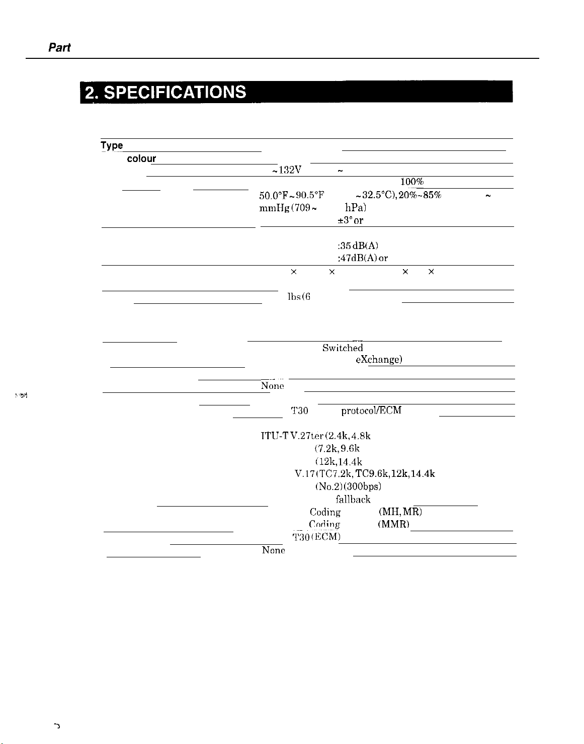
2.1 General Specification
TYPT
Body colour
Power source
Power consumption
Usage environment.
Operating noise
Dimensions (W X D X H)
Weight
Desktop
Art gray
98 - 132V AC, 48 - 62 Hz,
standby 9 W/Max. 49 W (when
50,O”F mmHg (709 - 1013 hPa)
Horizontal
Measured in accordance with IS0 standards
Standby
Operating
15.75” x 14.37” x 8.07” (400 mm x 365 x 205 mm)
(Not including Trays)
13.23
2.2 Communication Specification
Applicable lines
_
Applicable Services
Handset
Transmission method
Transmission control protocol
Modulation method
G3 image signals
G3 procedure signals
Coding
Error correction
Canon express protocol (CEP)
PSTN (Public Switch&l Telephone Network)
PBX (Private Branch
_
DRPD
N&c
Half-duplex
ITU-T
TTIJ-T
ITU-T V.29 (7.2k, 9.6k bps)
ITU-T V.33
ITU-T V.17 (TC7.2k,
ITU-T V.21 (No.2) (300bps)
(With automatic fallback function)
ITU-T T.4
ITU-T T.6
ITU-T T30
NOllC
90.5”F (10°C - 32.5”C),
*3” or less
:35
dB(A) or less
:47dB(A) OT less
111s (6
0 kg) Including trays
exchange)
‘~30
binary protocol/ECM protocol
V.27ter (2.4k, 4.8k bps)
(12k,
14.4k bps)
TCS.Gk, 12k,
C:oding
method (MH, MR)
&dine
method (MMR)
(E&j
100%
black copy)
20%-85%
14.4k bps)
_
RH, 532 - 760
1-2
Page 18
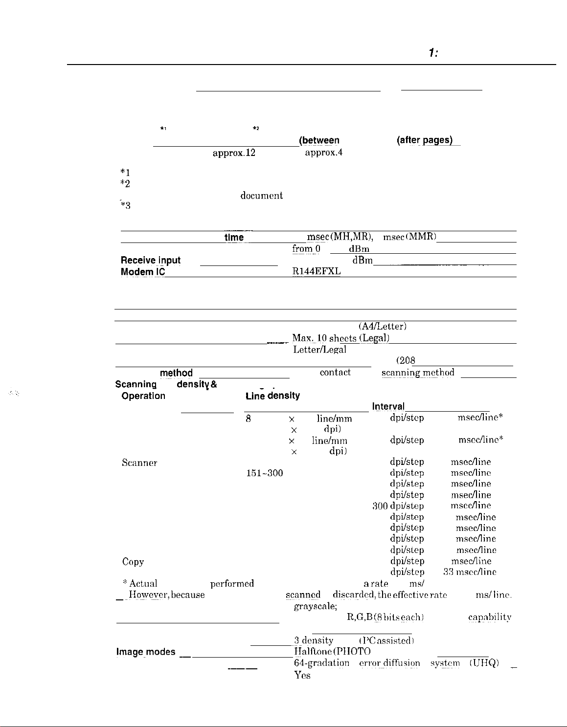
Time required for transmission protocol
Chapter 7: General Description
Pre-message
Protocol
Mode
Stand&/Fine
*l
Time from when other facsimile is connected to the line until image transmission begins.
*2
Post-message (between pages): Time from nftcr one document has been sent until
‘*3
Post-message (after last pages): Time from after image transmission is completed until
Minimum transmission
Transmission output level
Receive_i_nput
Mo&m!C
2.3
Scanner Specification
Type
ADF capacity
Effective scanning width
Scanning
Scanninq
Opera&n Mode
FAX
COPY
*Actual
~
~Howc~cr,
Scanner gradations
TWAIN
Scanning density adjustment
lmage_modes ~~
Halftone (fax and copy)
Prescan
‘1
transmission of the next
line is switched from facsimile to telephone.
level
method
line dens@ & Scanning speed
Standard
Fine
Text (Binary)
Gray scale
Full color
B&W
Full color
scanning is
becnuse
Protocol
approx.12
_
performed
1 of every 3 lines
*I
sec.
document
tim_e--
__..___ Max,10 sheets
Line dknslty
8
dot/mm x 3.85
(203.2 dpi x 97.79 dpi)
8 dot/nun x 7.7
(203.2 dpi x 195.58 dpi)
150 dpi or less
151-300
301-600 dpi
150 dpi or less
151-300 dpi
301-600 dpi
150 dpi or less
151-300 dpi
301-600 dpi
360 dpi
360 dpi
in 150 dpi increments at B
~~~~
Post-message Post-message
Protocol l I
(be@een
approx.4
starts if several pages are transmitted.
10 msec (MH,MR), 0 msec
from.0 to -15
from -3 to -43 dBm
B144EFXL
Sheets
Max. 20 sheets
Letter/Legal
A4
Color
dpi
scanned
grayscale;
___ color;
YCS
-3-density
~Jalflor~e
Wgrndiltion crror&ffusign yy$em
Yes
pages)
sec.
dBm
contnct
line/mm
linclmm
is discardccl,
sensor
8 bit, 256 gradations
R,G,B (8
level tl’C
(PIIOTO mode)
(A4/Letter)
(Legal)
8.42” (214 mm)
8.19”
scanningm$hod
Motor step
lfiterval
150
dpiktcp
150
dpi/step
150
dpiktcp
300
dpikcp
600
dpilstep
150
dpikep
300
dpiktep
600
dpikcp
150
dpi/step
300
dpiktcp
600
dpilslep
600
dpiktep
600
dpiktup
rate
of 5 ms/ line
the
effective
bits
nssistedl
(aftewg*
approx.3.5 sec.
(MMR)
_
(208
mm)
rntc
each) full color
Scanning speed
7.5 msecAine”
7.5 mscc/linc“:
5
msccfline
5
msccflinc
5 msecAine
7
msecfline
7
mscclline
11 msccAine
21 msccAine
21
ms&line
33 msccAinc
5
mseclline
:13 “xccllinc
is 7.5
IIJNQ)
ms/ linr.
capnbility
_
l-3
Page 19
Pari
1: Facsimile
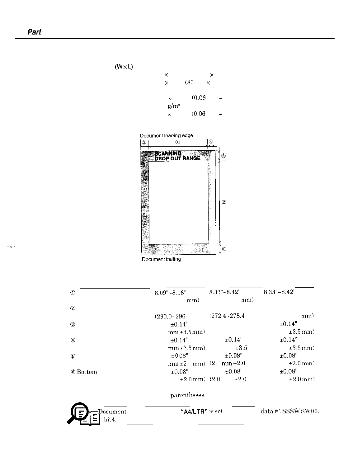
Scanning range
Sheet dimensions (W x
Maximum
Minimum
Thickness
multiple pages:
single page:
L)
8.50” x 39.3” (216 mm x 1000 mm)
3.15” x 1.77”
0.002” - 0.005”
40-90
0.002” - 0.017” (0.06 mm - 0.43 mm)
40-340 g/m’
SCANNING RANGE
g/m2
(80
mm x 45 mm)
CO.06
mm - 0.13 mm)
Document
Figure l-l Scanning Range
Item
0)
Effective scanning width
0
Effective scanning length
0
Left margin 0.04” *0.14”
0
Right margin
0
Top margin
(6)
Ruttom margin
Units arc inches with mm shown in
E- Documet~t
NOTE
scanning width
A4
8.09”-8.18”
(205.5-208 mm)
11.54”
(290.0-296
(1.0
0.04”
(1.0 I”“1
0.08” *O
(2.0
0.08” iO.08”
(2.0 mm
trailing
edge
mm)
,““I
*3.5
zkO.14”
*3.R
08”
“11”
*2 0 mm)
k2.0
parenth~~srs.
“A4/LTR
mn1)
mm)
mm)
Letter_
8.33”-8.42”
(211.5-214 mm)
10.84”
I272.4-278.4
0.08” k0.14”
(2.0 mm e3.5 mm) (2.0 mm
0.04” *0.14”
(1.0 mm
0.08” *0.08” 0.08” +0.08”
(2
0
“ll”
0.08” iO.08” 0.08” ~0.08”
(2.C
mm
” ii wt
in service data #l SSSW
mm) (348.6-354.6 mm)
*3.R
k2.0 mm) (2.0 mm e2.0 mm)
+2.0
Legal
8.33”-8.42”
(211.5-214 mm)
13.84”
0.08” +0.14”
0.04” iO.14”
mm) (1.0 mm k3.5 mm)
mm) (2.0 mm
*3.5
*2.0
_
mm)
“II”~
SWOG.
1-4
Page 20
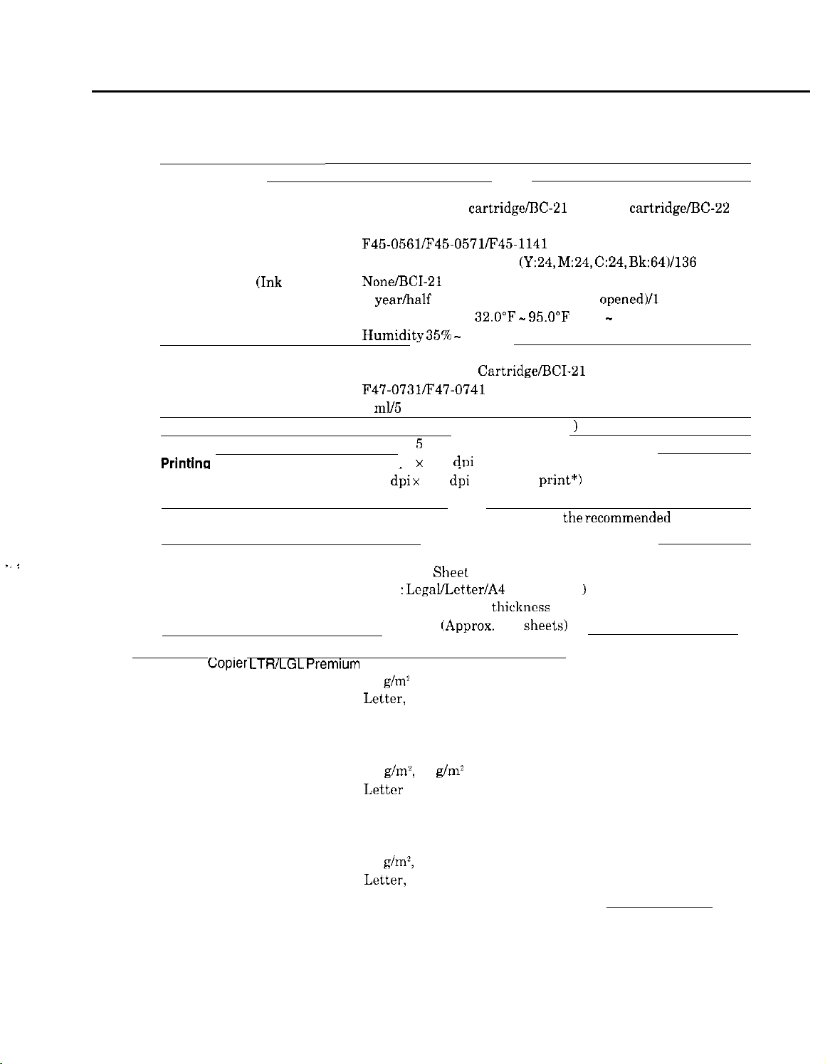
2.4 Printer Specification
Chapter 1: General Description
Printing method
BJ Cartridge
Products name
Product code
Print head
Ink cartridge
Valid period
Storage conditions
Ink Cartridge
Products name
Product code
Ink contains
Ink detection
Printlng speed
Printina
Paper output tray stacking
. .
:
Paper tray
Recommended paper
Canon
resolution
*Printing in a checkered pattern without printing vertical and horizontal adjacent dots.
Paper supply method
Number of paper tray
Paper capacity
Copier LTRlLGL Premium
Wright
Paper size
Manufactured by
(Ink
tank)
Bubble-jet ink on-demand
BC-20 Black BJ
Photo Color BJ cartridge
F45-0561/F45-0571/F45-1141
128 nozzles/136 nozzles
None/BCI-21
1 year/half a year (since the seal was
Temperature
Humidity35% -
BCI-21 Black Ink
F47-0731/F47-0741
9
ml/5
ml each of YMC
Yes
(Directly detects ink ejection
Approx. 5 pages/minute (in case of character print)
360 dpi x 360
180
d;i x
180
Approx. 50 sheets (when using
Approx. 20 sheets (when raised output guides)
ASF (Auto
ltray :
Lcgal/Lctter/A4
Max. 0.40” (10 mm)
plain paper
Paper
75
g/ma
Letter,
Legal
BOISE CASCADE
cartridge/BC:-21
(Y:24, M:24, C:24,
Color or BCI-21 Black/None
32.O”F - 95.O”F
65% RH
Cartridge/BCI-21
dpi
(Normal print)
dpi
(Economy
Sheet
Feeder)
(Universal
thickness
(Approx.
100
Color BJ cartridge/BC-22
opened)/1
(0°C - 35°C)
Color Ink Cartridge
1
print*)
the recommended
)
sheets)
Bk:64)/136 nozzles
year
paper)
PLOVERBOND
Weight
Paper size
Manufactured by
XEROX 4024
Weight
Paper size
Manufactured by
75
g/m’,
90
g/m2
Letter
FOX RIVER
75
g/m~,
90 g/m’
Letter,
Legal
XEROX
1-5
Page 21
Part 1: Facsimile
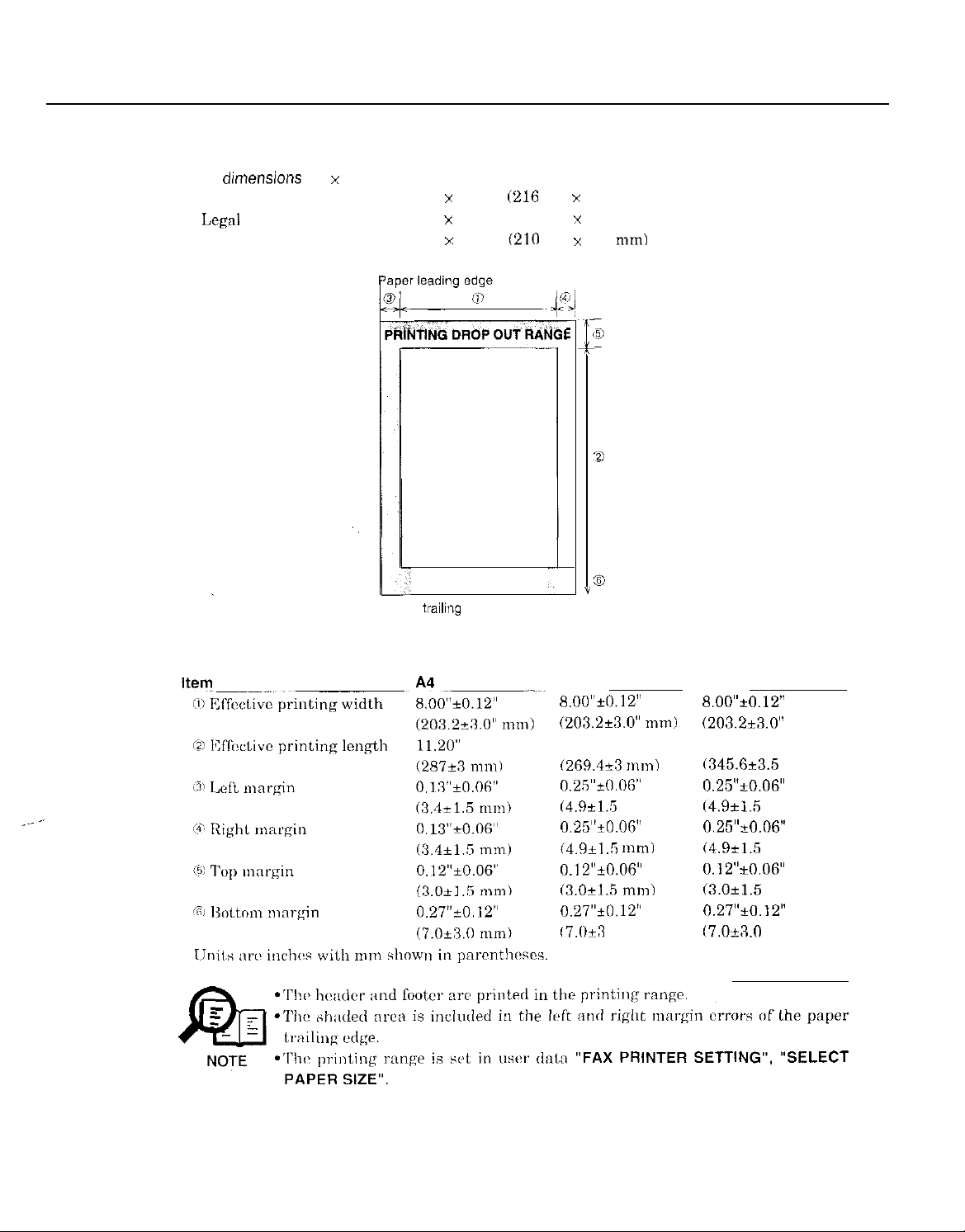
Printing range
Paper
Letter
Legal
A4
dunensions
(W x L)
8.50” x 10.98”
8.50” x 14.02” (216 mm x 356 mm)
8.27” x 11.69”
(216
mm x 279 mm)
(210
mm x 297 mm)
z_
i
(
1
PRINTING RANGE
Y
Paper trailing edge
Figure 1-2 Printing Range
Letter
8.00”t0.12”
(203.2+3.0” mm)
10.51”
(269.4+3 mm)
0.25”+0.06”
(4.9k1.5 mm)
0.25”+0.OF” 0.25”+0.06”
(4.9+1 .R tn111~
0.12”&06”
(3.0+1.5 mm)
0.27”+0.12”
17.0&l 0 mm)
Legal
8.00”~0.12”
(203.2i3.0”
13.47”
(345.6t3.5
0.25”kO.O6”
(4.9*15
(4.9k1.5 mm)
0.12”iO.O6”
(3.Ok1.5
0.27”*0.12”
17.0+X0
mm)
mm)
mm)
mm)
mm)
l-6
Page 22
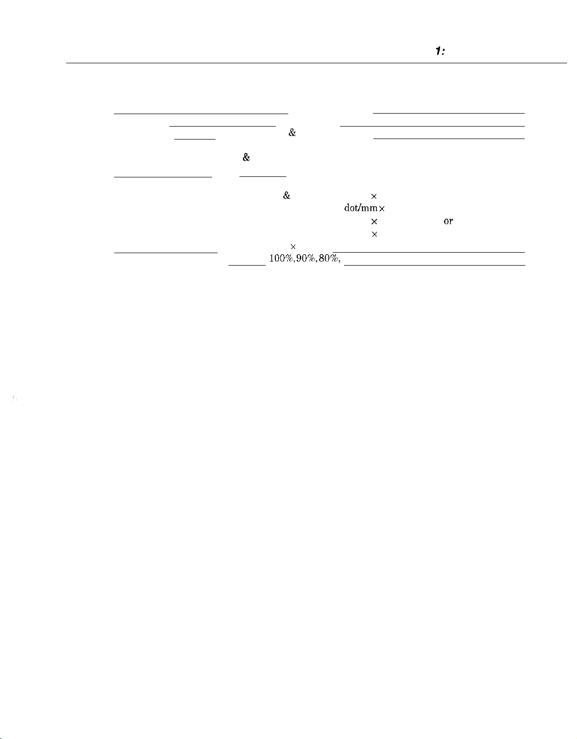
2.5 Copy Specification
Chapter 7: General Description
Color copy
Multiple copy
YCS
99 copies (Black
Copy mode
Black & white B&W TEXT, B&W PHOTO
Color
Copy resolution
Scanning
Printing
Copy magnification ratio
&
white mode only)
COLOR FINE, COLOR STANDARD, COLOR SNAPSHOT
Black & white 360 dpi x 360 dpi (direct copy)
8 dot/mm x 7.7 line/mm (memory COPY)
Color 360 dpi x 360 dpi (FINE or SNAPSHOT)
180 dpi x 360 dpi (STANDARD)
360 dpi x 360 dpi
loo’%,
90’%,
807q 70%
1-7
Page 23
Part 1: Facsimile
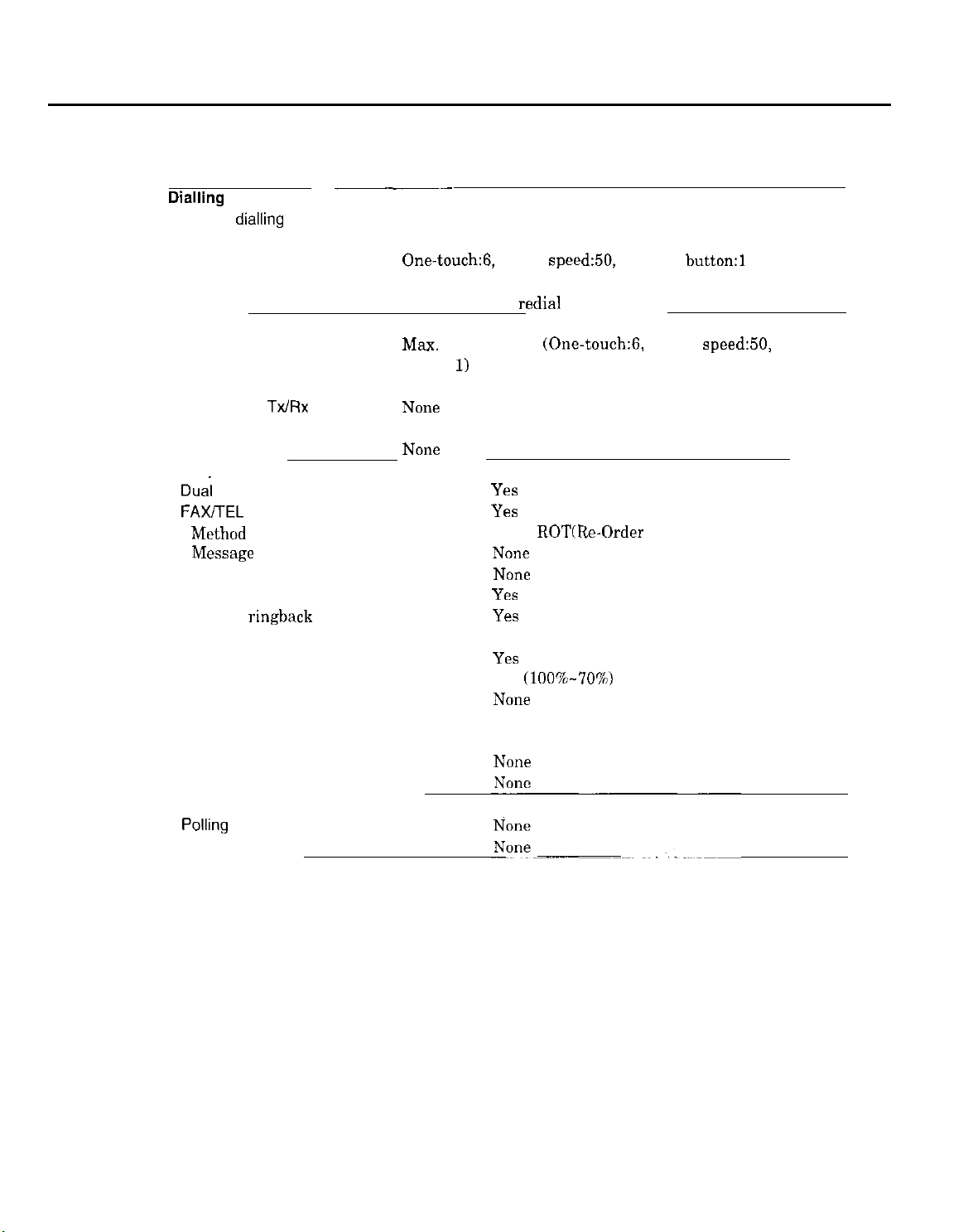
2.6 Function
Dialling
Manual dialling Numeric button
Auto dialing Max. 120 digits
Group dial Max.55 locations
Redial
Transmission
Broadcast transmission
Delayed transmission Yes (PC Assisted)
Confidential
Relay broadcasting originating None
Relay broadcasting
Reception
Dual Access
FAX/TEL switching
Method
MiSage
Pseudo CI
Pseudo ring
Pseudo
TX/RX
ringback
__
tone
~.~_
One-touch:B, Coded speed:50, Numeric
Numeric button
Max.
57 locations
button:
N0Ile
NOIE
1)
redial
function (Max. 120 digits)
(One-touch:6,
Coded
Y‘.ZS
Yes
CNG,
ROT(Rr-Order
NOIX
NOW
Yes
YE3
Tone) detection
button:1
speed:50,
Numeric
Reduction settings for reception
Automatic reduction of reception images
Built-in Answering machine
Answering machine connection
Remote reception
Memory lock reception
Reception printing in reverse order
Polling
Polling transmission
Polling reception
Yes
Yes (1007&70%)
NOW?
Yes (Telephone answering priority type)
Yes (Remote ID method)
NOW
1-8
Page 24

Chapter 1: General Description
Others
Closed network
Direct mail prevention
Reception printing In reverse order
Memory box
Memory backup
Backup contents
Backup IC
Backup device
Battery life
Image data backup
Activity management
a) User report
Activity management report (Every 20 transactions : always transmission and reception
together)
Activity report (sending/receiving)
One-touch speed dialling list
Coded speed dialling list (by SPECIAL MODE)
Group dialling list
Memory clear list
User’s data list
Multi activity report
b) Service report
System data list
System dump list
Error list
N0ne
NOIE
Nona
N0na
Dial registration data, User data, Service data,
Time
256 kbit SRAM for control
Lithium battery
Approx. 5 years
Nona
Yes
(by SPECIAL MODE)
(by SPECIAL MODE)
(by SPECIAL MODE)
3.OV DC/600 mAh
1-9
Page 25

Part
7: Facsimile
Transmitting terminal identification
Time
Management data
Precision
Display
Completion stamp
Program key
Telephone exchange function
Speaker phone
Demo print function
HELP function
Ye.3
Year/month/date/day/hour/minute (24 hour
display)
?r90 set
NOIE
NOIW
NOFX
NOlIe
NCJne
NOIE
lrow x
per month
16 digits
l-10
Page 26
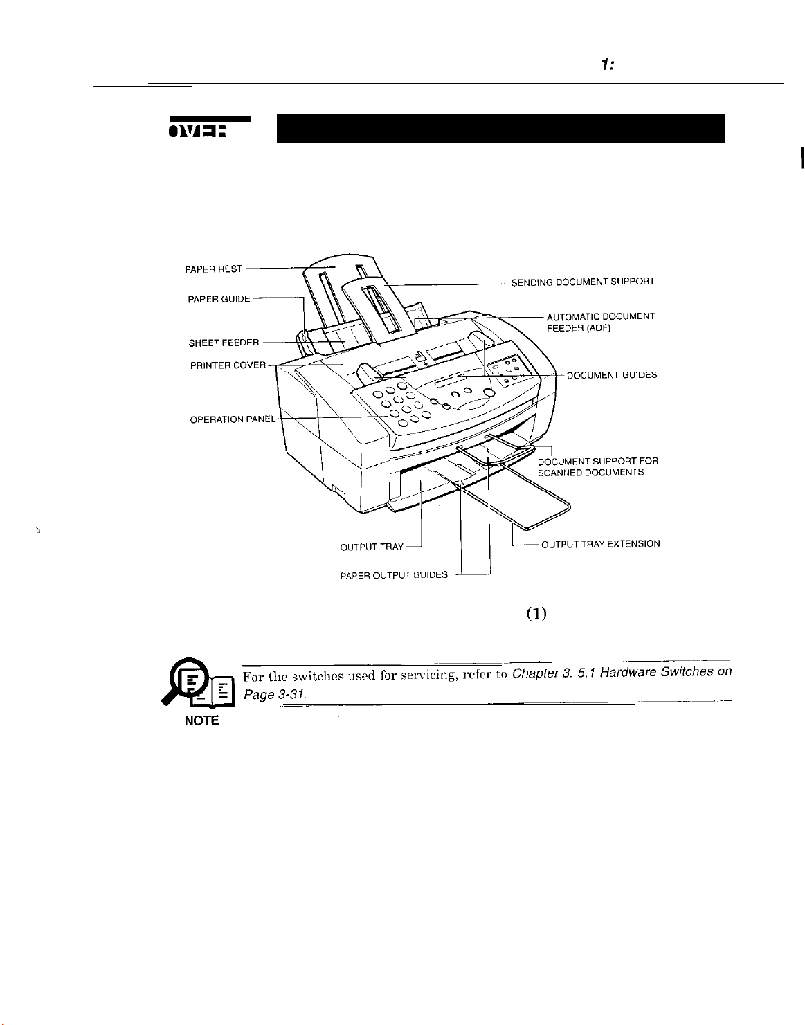
3.1
External View
Front View
Chapter 7: General Description
Figure 1-3 External View
l-11
(1)
Page 27
Part 1: Facsimile
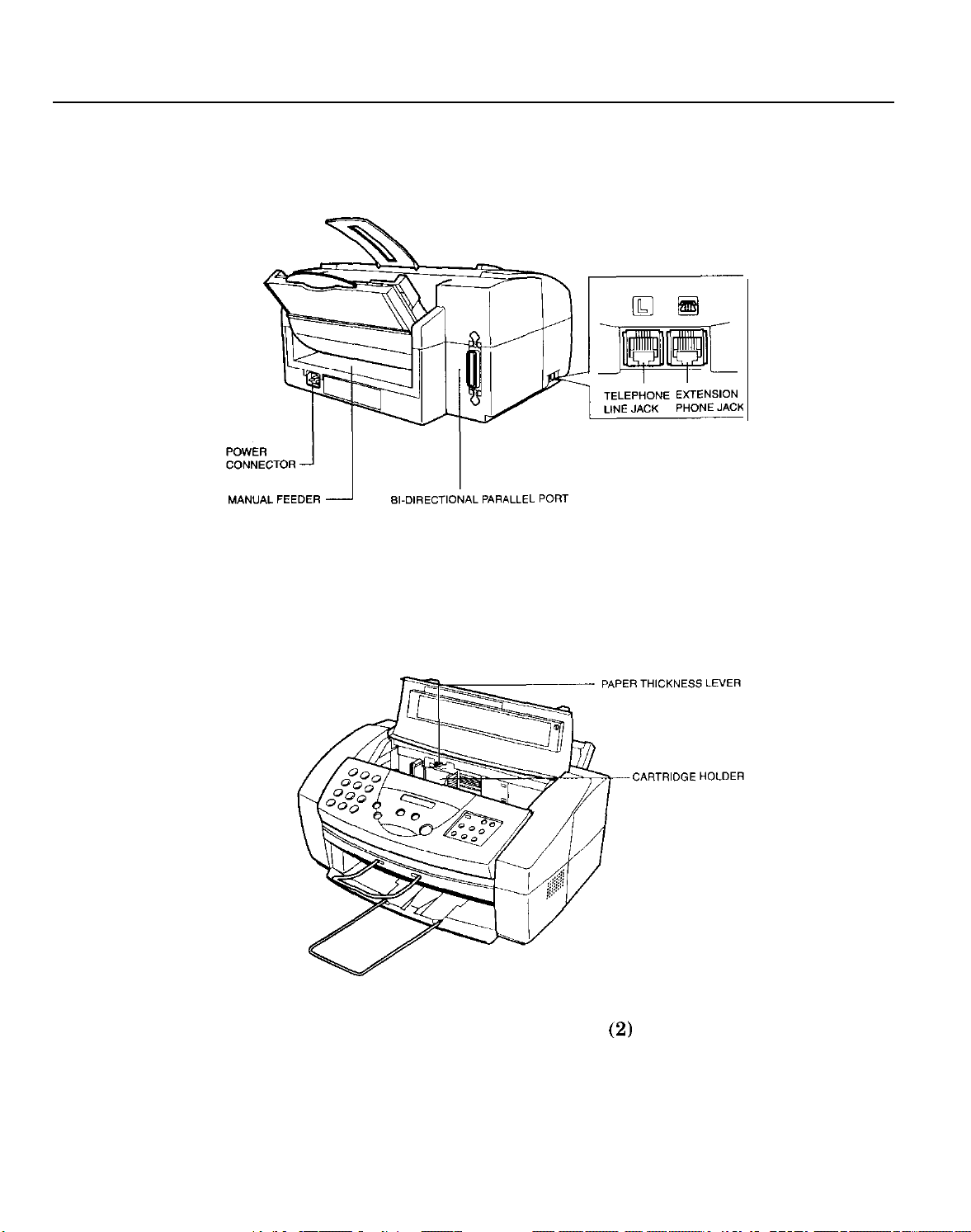
Rear View
Inside the Printer Cover
Figure 1-4 External View
(2)
1-12
Page 28
Part 7: Facsimile
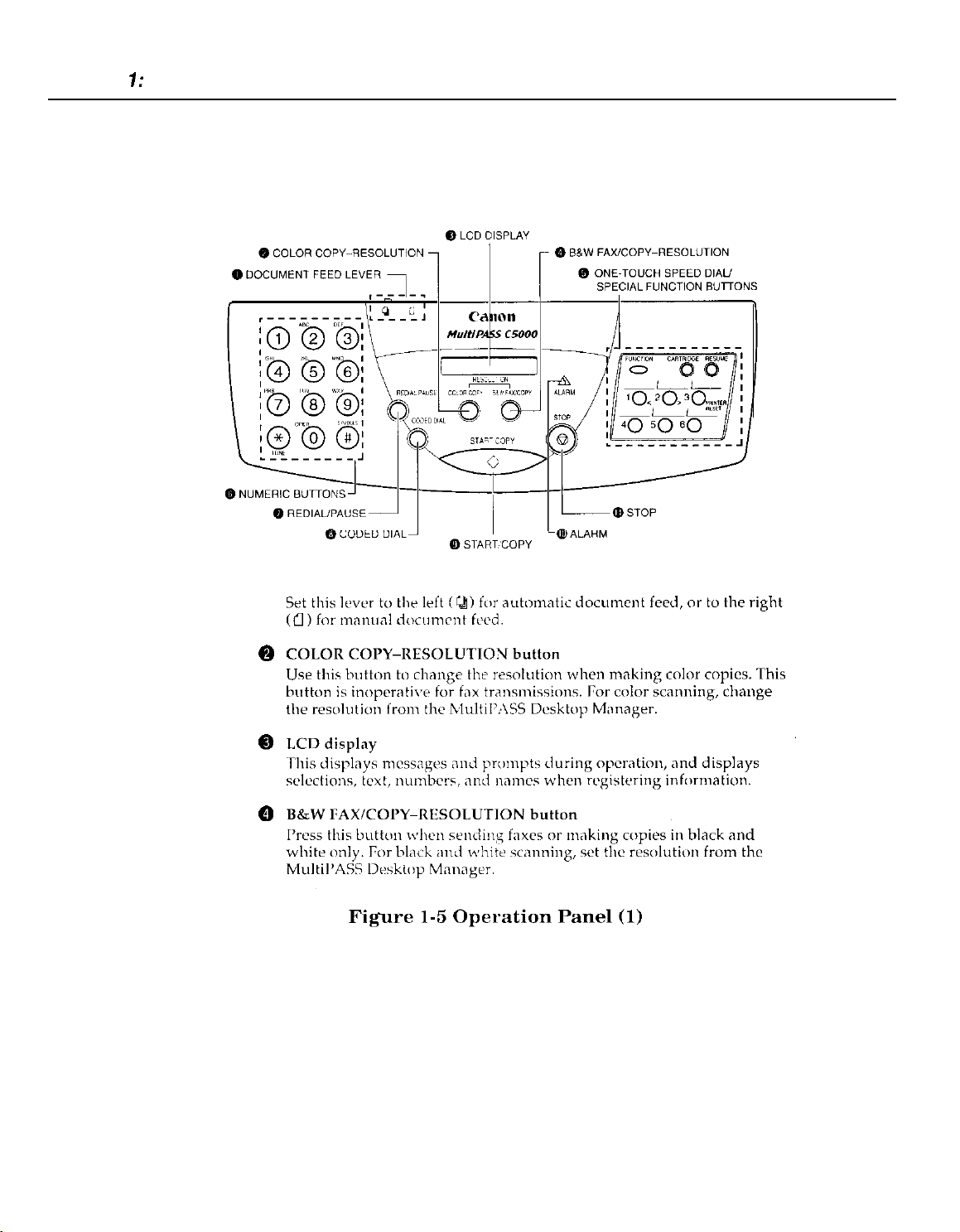
3.2
Operation Panel
The Operation Panel
Document feed lever
0
0
0
0
1-14
Page 29
Chapter 7: General Description
@
One-Touch Speed Dial/Special Function buttons
Use these buttons for one-touch speed dialing, entering user
information,
print head. For more information on the special function buttons.
@
Numeric buttons
Use
thcsr
information,
for automatic dialing.
prmting
buttons to type numbers and names when entering
and
documents stored in memory, and cleaning the
to dial fax/telephone numbers that
are
not
registrred
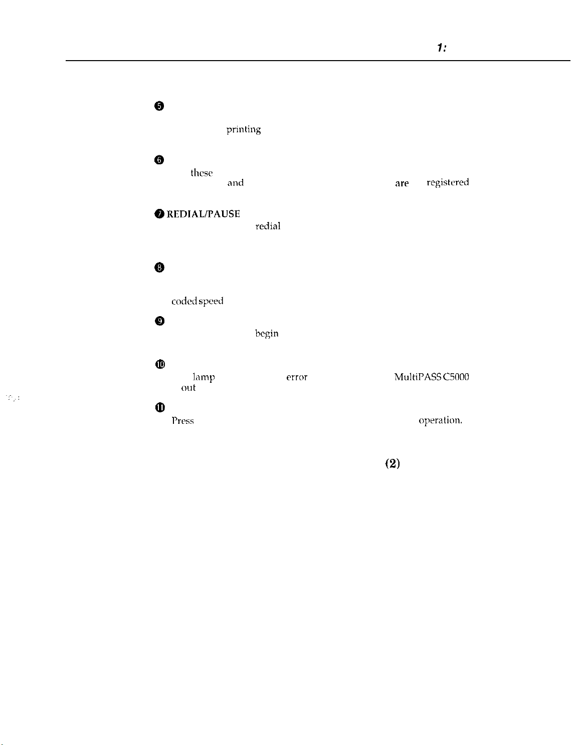
@ REDIALPAUSE
Press this button to
number buttons, or to enter pauses between digits when dialing fax
numbers.
@
CODED DIAL button
Press this button (followed by entering a two-digit code with the
numeric buttons) to dial a fax number that you have registered for
coded speed
@
START/COPY button
Press this button to
operations, or to select functions when registering information.
@I
ALARM lamp
This
lamp
is
out
of paper or ink.
@
STOP button
Prtx
this button to cancel sending, receiving, or any other
button
redial
the last number that was dialed using the
dialing.
begin
sending, receiving, scanning, or other
flashes when an
error
occurs, or when the
Figure 1-6 Operation Panel
MultiPASS
(2)
C5000
oprration.
1-15
Page 30
Part 1: Facsimile
0
0
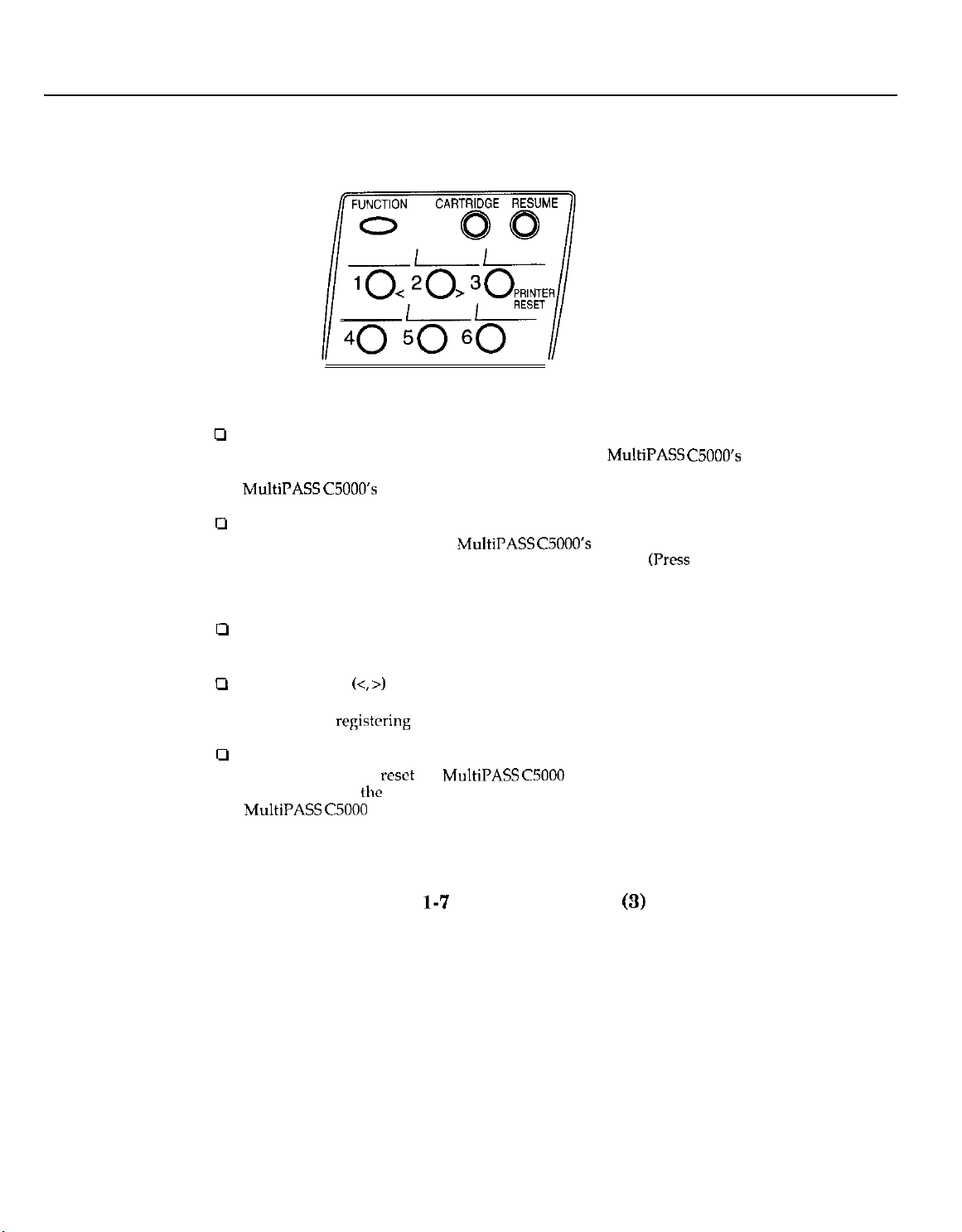
Special Function Buttons
FUNCTION button
Use this button to enter user information, to run the
self-cleaning process, check the nozzles, or to print faxes stored in the
MultiPASS C5OOO’s
CARTRIDGE button
Press this button to release the
its center position for installing or replacing the cartridge.
after installing the cartridge to return the cartridge holder back to its
home position.)
memory.
MultiPASS C5OOO’s
MultiPASS C5OOO’s
BJ cartridge holder to
(Press
again
u
RESUME button
Press this button when you want to form-feed paper when printing
cl
Arrow buttons
Use these buttons to scroll through menu selections or to move the
cursor when
cl
PRINTER RESET button 3
Press this button to
will maintain all
MultiPASS
(<, >)
1 and 2
registering
C5000 to reset the unit or the faxes in memory will be lost.
Figure
data.
reset
the
MultiPASS CSOOO
the
faxes currently in memory. Do not unplug the
l-7
Operation Panel
if your PC crashes. This
(3)
1-16
Page 31

Chapter 7: General Description
Entering a Name
When
entering
a number and a group of uppercase
The chart below shows which number to press for each character.
a
name
(such as “Unit Name”), each numeric button has
and
lowercase letters assigned to it.
Button
1
2
3
4
6
7
8
9
0
#
Figure
Characters
1
ARCabc2
DEFdrf3
GHIehi4
MNOmnoh
I’QRSpqrs7
TLJVtuv8
WXYZwxyz9
0
-.‘#!“,;:“‘_=/ I’?$Q%&+oIloo
l-8
Operation Panel
(4)
1-17
Page 32

Part 1: Facsimile
3.3 Consumables
3.3.1 BJ cartridge and ink cartridge and BJ cartridge container
Choosing the Best Cartridge
a
Note
Canon offers several BJ print cartridges and ink tanks for use in
MultiPASS
while BJ ink tanks contain only ink.) Use
decide which type of cartridge best suits your particular needs.
To avoid printing problems, use only the BC-21/21e BJ cartridge for
normal printing (or the separately sold UC-20 Black BJ cartridge, if
rarely print color). The BC-22/22r Photo Color BJ Cartridge (sold
separately) is for printing photo-realistic color images. Other cartridges
can produce unsatisfactory results. In addition, use only
and BCI-21 Color ink tanks in the BC-21/21e Color BJ cartridge.
BC-21/21e
The BC-21/21e incorporates a UJ pnnt head
and two replaceable ink tanks (a BCI-21
Black and a BCI-21 Color). Use this cartridge
for
nonml
C5lKtO.
(BJ print cartridges contain the BJ print head and ink,
Color BJ Cartridge
printing.
the
following
dcscriptims
BCI-21
the
to
you
Black
EC-21 /21e
Color BJ cartridge
1-18
Page 33

Chapter 1: General Description
BC-W22e
Includes the print head
single unit. Use this cartridge for printing
photo-realistic color images.
BC-29F Fluorescent BJ Cartridge
Includes the print head and
single unit. Use this cartridge for printing
bright, attractive fluorescent colors. For
optimum print quality, use High Resolution
Paper HR-101.
The
the
feature: because the
have ink tanks that can be replaced separately), using them to print
faxes will use the black ink faster, using up the cartridges while they still
have a considerable amount of
SB-21 BJ Cartridge Container
Use the 58-21 to store an
in a
from drying out.
Photo Color BJ Cartridge
MultiPASS
BC-22/22e
convenient
C20 cannot print incoming
or BC-29F cartridge is installed. This is an ink-saving
BC-22/22e
location, Tvhile keeping it
and
color ink in a
colour
and
colour
extra BJ
ink in a
K-2YF
ink remaining.
cartridge
faxes
or make copies while
are single units (and do not
Your
MultiPASS
Cartridge (which incorporates the IICI-21 Black and
tanks) and an additional
ink, or if you wish to
above, you can purchase them from your Canon dealer.
C5000 unit comes with a BC-21 or
BCIL21
Black ink tank. When you
11s~ ,my
other Canon BJ cartridges mentioned
Figure l-10 Consumables
BC-2Ic
BCI-21
(2)
1-19
Color BJ
Color ink
run
out of
Page 34

Part 1: Facsimile
Page 35

Chapter 1: General Description
Canon Glossy Photo Paper GP-201
Canon Glossy Photo I’aper (;I’-201 is a high gloss, thicker paper that
produces the look
22/22e Photo BJ
printer. (Select Glossy Paper in thr printer driver when you have this
paper loaded.)
and feel (If ,I ph<~tograph
Cnrtridgtz tu pmducc
Use this paper with
photo-realistic prints from your
the
BC
Canon High-Gloss Film
This is a high-grade,
and mcm vivid color output than is possible with coated paper. This
film provides the
cartridge. Use this film fw
presentations,
Fabric Sheets FS-101
These legal-size, white, cutton fabric sheets are specifically designed for
Canon BJ Color printers,
cross stitch, pillows, holiday stockings, and other craft
T-Shirt Transfers TR-IO1
bet
and
Figure l-12 Print Media
HG-101
letter-4/e
color t,rint quality for the BC-21/21e Color BJ
whrn
gloss film that lets you create sharper
trxlr
show displays or other special
p~intmg
~IKI
at 720 x 360 dpi resolution.
enable you to print your own designs for
prqects.
(2)
1-21
Page 36

Part 7: Facsimile
r
w
Units
: mm
Figure l-13 Dimensions
--
0
,-r
400
~-
--
-
l-22
Page 37

5.1
Personnel Hazards
Electrical Shock and High-Temperature Parts
Chapter 1: General Description
Power
supply
Page
l-25
Paper feed motor
Page l-25
BJ cartridge
(Alminlum plate)
PAGE l-25
(-132 F)
(-212~F)
’ -
‘SCNTb&
Page l-25
Carriage motor
Document feed
motor
(-145.2~F)
(-
113 F)
Figure 1-14 Personnel Hazards
l-23
(1)
Page 38

Part 1: Facsimile
Moving parts
01’
Page1 -26
1
Preventing ink stains m
Pagel-
Figure
l-15
Personnel Hazards (2)
Purge unit
/
Carriage belt
l-24
Page 39

5.1.1 Electrical shock
Chapter 7: Genera/ Description
Electrical shock hazard
*To
prevent electrical shock, be sure to disconnect the power cord and modular jack
_
e
c
_
RIJ
A
@n
NOTE
5.1.2 High-temperature parts
c
- -
NOTE
before disassembly.
*Remove grounding wrist straps before servicing this unit while the FAX’s power is
on. Otherwise, electrical shock may occur.
bower supply unit
r
When power is supplied to this unit, 120 VAC
-5
Telephone
If a telephone line is connected to this unit, 48 VDC will be supplied by this line.
When a call signal is received, a voltage of 90 VAC
High-temperature warning
To prevent skin burns, disconnect the
10
minutes to allow hot parts to cool.
How
Heat of about 122°F or more causes burns. Also, the longer the contact, the mow
c
severe the burn.
When treating a burn, the first minute after receiving the burn is
important. Cool the burn immediately with cold running water. In
serious burn, seek medical attention immediately.
line
to treat burns
I
will be supplied to the primary side.
Vrms
____~
powcr
cord and let this unit stand for at least
_.
will be supplied.
the
case
most
of a
.
nn
r
- -
NOTE
The parts which get hot during operation are indicated. For the location of
in
parts, refer to
(Ambient
Document
Paper feed motor (approx. - 132°F
Carriage motor (approx. - 145.2-F
Power supply unit (Max. - 185°F
PCNT board
BJ cartridge (nmx. -
the
figures.
temperature
feed motor (approx. -
assrmbly
95°F
(approx. -
212°F
(35°C)
continuous copy
113.9”F (45.5”C))
(55.6”C))
(62.9”C))
(85.2%))
173.1”F (78.4”C))
(100°C))
l-25
operation)
thcsc
Page 40

Part 1: Facsimile
5.1.3 Fire hazards
5.1.4 Moving parts
e
Do not dispose in fire.
Do not dispose of lithium batteries in fire. Doing so may rupture the battery
and expose flammable materials.
Follow applicable local
assembly’s lithium battery.
Fire hazard
When using
internal electronic circuits can ignite the solvent. Before using such solvents,
be
sure
parts cool. Use the solvent in a well-ventilated area.
Moving parts
To prevent mishaps due to moving or rotating parts during servicing, be
to disconnect the power cord before disassembly.
Since the this unit does not have a
and
rollers
operation. If the printer cover must be opened during printing,
moving parts.
Figure l-14 shows the driving s&ion’s location.
IPA
or other solvents during servicing, heat or sparks from
to turn off the power source and wait until the
will not stop even if the printer cover is opened during a printing
regulations
when disposing of the the SCNT board
high-temperature
sensor
on
the
printer cover, the carriage
bewnrr
of the
sure
5.1.5 Preventing ink stains
Avoid touching the BJ cartridge ink nozzles, ink pad, head cap, head wiper,
absorbers. The ink can stain your hands,
is
permanmt
c
- -
&
NOTE
nnd will permanently stain clothing, ptr.
Although the ink is not toxic, it
67-63-O). If the ink enters the
L
water and
immediately and
see a doctor. If the ink is
giw thr informntion
clothes,
etc. Although the ink is
contnms
eyw accidentally,
an organic solvent (isopropyl nlcohol
swallowrd
printed on the
watrr soluble,
flush the eyes with running
accidentally, see a doctor
B.J cnrtridgo
lnbcl.
and
ink
it
l-26
Page 41

5.2
General Cautions
5.2.1 Unit cautions
Safety Instructions
Chapter 1: General Description
A
Caution
Read these safety instructions thoroughly before using your
C5000, and keep them handy in case you need to refer to them later.
Except as specifically described in this manual, do not attempt to service
the
MultiPASS
opening and removing its interior covers will expose you to dangerous
voltages and other risks. For all service, contact your local authorized
Canon dealer or service center.
Cl
Always follow all warnings and
MultiPASS
U Use the
the
U Do not use the
into the unit, unplug it immediately and call your local authorized
Canon dealer or
0
The back and bottom of the
openings for ventilation. To keep the
overheating (which
fire risk), take
operate the unit on a bed, sofa, rug, or
near a radiator or other heat source. Du not
C5000 in a
ventilation is available See “Choosing a
MultiPASS
the unit needs for ventilation
0
Operate
indicated on the unit’s label. If
available
0
The
third pin is a grounding pin) that fits only into
outlets.
the correct type, contact an
2
&pter,
purpose.
C5000 yourself. Never attempt to disassemble the unit:
instru tions
C5000.
MultiPASS
MultiPASS
closet
C5000” on
the MultiPASS C.iOOi)
from your xvall outlets, contact your
MultiPASS
This is a safety feature. If the outlet you intend to
as this
C5000 only on n sturdy, stable, level surface. If
C5000 falls, it could be seriously damaged.
MultiPASS GO00
service
center.
can
cause it to operate abnormally
cart
not to block or
or cabinet or on
page
C5000 has a three-prong, grounding-type plug (the
defeats
the three-pronged plug’s grounding
near water. If you spill liquid on
MultiI’ASS
cover
shelves
2-3 for
guidclincs
Only from
you are
elrctri&n
marked on the
C5000 include slots
MultiPASS
these openings. Do not
other
unless adequate
I.ocation
not
to
rcplacr
C5000 from
similar soft surface, or
place
the
for Your
on how much space
the type
suw
of the type of power
Irxal
gr<>undiIlg-type
it: do not
MultiPASS
and
and
create a
MultiPASS
of
power sowx
power company.
use
is not
use
a X-to-
or
1-27
181-11
Page 42

Part 7: Facsimile
U
Do not allow anything to rest un the
MultiPASS CSOOO
cord is not knotted or kinked.
0
Do not insert objects of any kind into the slots or openings on the
MultiPASS C5OOO’s
points or short out parts, and result in fire or electric shock.
3 Do not allow small objects (such as pins,
fall into the
the unit immediately and call your local authorized Canon dealer or
service center.
Ll
Always unplug the
0
Whenever you unplug the
seconds before you plug it back in.
0
Keep the
damage it. If you have to place it near a window, install heavy
curtains or blinds.
0
Do
fluctuations. Install the unit in H
range 5LI~90.5°F
3 Always unplug the
a
I3rfore
c1
Always lift the
sheet
MultiPASS
not expose the
you transport the
feeder
where the cord will bc walked on Make
cabinet, as they could touch dangerous voltage
MultiI’ASS GO00
MultiPASS C5OOO
MultiPASS
C5000 away from direct sunlight, as this can
MultiPASS C5tlOO
(lo”-323°C)
MultlPASS C.5000
MultiPASS CSOOO,
MultiPASS
or document supports.
C5000 as shown below.
power
paper
If something
before moving or cleaning it.
C5000, wait at
to extreme
plnce
with temperatures in the
during thunderstorms.
cord or place the
clips, or staples) to
does
fall into it, unplug
Irast
five
temperature
remove its
Ncvcr
L3J
cartridge.
lift it by its
swc
the
IBl-12
l-28
Page 43

Chapter 1: General Description
0
Unplug
Canon dealer or
l
l
l
l
l If the
l If the
FCC rules governing the use of fax equipment, require that you register
your fax number, your
in
the MultiPASS
User Information in the
the MulWASS
If
the
power cord or plug is damaged or frayed.
service
C5000 and
center in
co&+ct
your local authorized
any
of these situations:
If liquid spills into the unit, or if it is otherwise exposed to rain
liquids.
If you notice smoke or unusu~~l noises or odors coming from it.
If the
MulWASS
C5000 does not operate normally when you
follow the operating instructions. Adjust only those controls that
are covered by the operating instructions in this user’s guide,
or
you can damage the unit and require extensive repair work.
MultiPASS
M&PASS CSOOO
C5000 is dropped or
its
cabinet damaged.
begins performing poorly, and you
cannot correct the problem by using the procedures in Chapter 6,
“Trouhleshootinr.”
name or
C5000 before using it.
company name, and the date and time
For
instructions, see “Entering
MultiPASS
C5000”.
or
/
Ml-13
1-29
Page 44

Part 1: Facsimile
Choosing a Location for Your
MultiPASS
c5000
A
CaUtlon
Before unpacking your MultiPASS
choose the best location for it.
Please review the information provided in “Safety Instructions”, to
make sure you are installing your MultiPASS
Put the MultiPASS GO00 in a cool, dry, clean, well ventilated place:
0
l Make sure the area is free from dust.
.
Make sure the location is not affected by extreme
changes, and always stays between 50” and
32.5”C).
.
Make sure the area’s relative humidity is
and 90%.
Keep the MultiPASS
0
If possible, put the MultiPASS
0
outlet, to avoid the expense of installing a new one.
Place the MultIPASS GO00
0
A three-prong, grounded plug,
IIz) power. (This is standard for U.S. outlets; if you
contact an electrician to check the power for you.)
Place the MultiI’ASS GO00
0
Make sure you
fax machine, copier, scanner, and telephone.
Do not plug the MultiI’ASS
0
sppliancc
or copier. Such devices generate electrical noise that can interfere
with your MultiPASS
Set the MultiPASS
0
is strong enough to support its Ivcight (about 12.3
Make sure the locntian you choose provides
3
the MultiPASS
flow freely into and out of the unit. The figure below shows the
minimum space
such as an air conditioner, electric typewriter, television,
C5000
can
reach it easily, as
C5000’5
C5OOl)
C5000 tar adqtwte
required
C5000,
follow these guidelines to
C5OOO
away from
C5000 near
near
md that
war
CWOO
‘tbility to send or receive
on a flat, stable, vibration-free surface that
for the unit.
direct
an existing telephone
an electrical wall outlet that accepts
provides 120.volt AC
the PC you will be connecting it to.
you
will bc using it as a printer,
into the same circuit as an
ventilation, and to allow
for safe use.
Y0.5”F (10”
always
between 10%
sunlight.
have
lbs/5.6
enough
space around
temperature
and
(60
any doubts,
faxes.
kg).
paper
to
IB2-3
l-30
Page 45

Powering Up
Chapter 7: General Description
A
Ca”tlon o
Follow these guidelines when connecting your
power source:
The
MultiPASS CSOOO
only and requires 120 V AC. Do not use it outside the U.S. or
Canada.
Plug
the
0
prong grounded outlet.
Use only
0
cord or extension cord can cause the
malfunction.
Unplug the unit only by pulling on the plug itself.
0
cord.
Do not plug the
0
appliance such as an air conditioner, computer,
or copier. These devices generate electrical noise, which can
interfere with the
Make sure nothing is
0
cannot be walked on or tripped over.
Do not overload the electrical outlet. Make sure the total amperage
0
used by all
ampere rating of the outlet’s circuit
Make
0
properly closed, and that there are no documents in this
MultiPASS
the power
the
machines plugged into the outlet does not exceed
sure
that the operation
is intended for use in the U.S. and Canada
GOtlO only into a
cord that
MultiPASS
MultIPASS C5OOO’s
laying on
came
with the unit. Using a longer
C5000 into an outlet shared with an
the power cord, and that the cord
paw1
of the
MultiPASS
120-v&
MultiPASS C.5000
operation.
breaker.
AC, 60-H&
Never
elfctric
MultiPASS
C5000 to a
to
typewriter,
C5000 is
threc-
pull on the
the
arm
1-31
182-22
Page 46

Part
1:
Facsimile
5.2.2 BJ cartridge cautions
a) General cautions
Selecting and Installing a BJ Cartridge
Canon offers a number of Bubble Jet
of printing requirements. (The
BC-2.1 or
the best BJ cartridge for your needs, as well as how to install and
maintain
BC-2le
the
cartridge.
Color BJ cartridge.) This section describes how to
(BJ)
MultiPASS
cartridges to meet a wide range
C5000 comes with one
select
Guidelines for Using and Maintaining BJ Cartridges
The most important thing you can do to ensure the best possible print
quality, as well as extend the life of your
care of the
M&PASS C5OOo’s
Store cartridges at
Keep
cartridges in their staled containers until you are ready to
them.
Install the cartridge immediately after removing its print head cap
and protective tape.
Always use the cartridge within
When changing cartridges, always
SB-21 BJ cartridge container that
Do not remove the cartridge from the
necessary.
room
BJ cartridges following these guidelines:
temperature.
-
The ink in the BJ cartridges is difficult to
spilling ink, always bc
the
cartridges:
0
Do not attempt to
IL!
Do not shake or drop the cartridge, or tip the print head downward.
0
Kwp
BJ
cxtridgcs
sure
to follo~v these
dis,lswnblc or refill lhe
out of
~h~ldrcv~‘s
MultiPASS
one
year of unpacking it.
store
the unused cartridge in
comes
with the
MultiPASS
clenn
prccnutions when
reach
C5000, is to take
up if spilled. To avoid
cartridge.
MultiPASS
C5000 unless
C5000.
handling
USC
the
lB2-24
l-32
Page 47

Chapter 7: General Description
Hold the BJ cartridge by its
sharp edges around the print head, the silver plate on the bottom of the
cartridge, or the silver metal or circuit area on its
0
Make
sure
the BJ cartridge holder is in its home position (on the
right side of the unit) when you are not using the
If it is not in its home position, press the CARTRIDGE button.
Leaving it out of its home position will dry out the print head on the
cartridge.
0
Clean the print head when print quality is no
“Cleaning and Testing the BJ Cartridge Print Head” for instructions.
If
the print quality does not improve after five consecutive
cleanings, replace the ink tank or BJ cartridge.
0
Do not use a
tanks missing. Doing so can cause it to clog.
Cl
Do not remove the ink tanks from the
unnecessarily, or the ink in
n
Never attempt to refill an
BC-21/21e
sides
only. Do not touch the print head, the
side.
MultiPASS
longer
satisfactory. See
Color BJ cartridge with either of its ink
BC-21/21c
them
may clog.
empty cartridge.
Color BJ cartridge
C5000.
1-33
182-25
Page 48

Part 1: Facsimile
Maintaining BJ Cartridges
Cleaning and Testing the BJ Cartridge Print Head
One of the most important elements in maintaining your MultiPASS
C5OOO’s
regularly, and to replace the BJ ink cartridges and
needed.
The print head in the BJ print cartridge contains nozzles through which
ink is propelled onto the paper. To maintain the best possible print
quality, these nozzles need to be rleaned from time to time. Your
MultiPASS C5000 is equipped with a print head cleaning function that
does this.
If your printouts become faint or streaked, or if their quality otherwise
decreases, clean the print head as
If your printing is faded, you can often correct the problem by adjusting
the print density (contrast) and printing speed. (For instructions, see
MultiPASS
cleaning the print head.
excellent print
Drsktop Mmqcrfor Wirtdows” USEI’S Guide.)
quality
is to clean the
dcscribcd
BJ
below.
cartridge’s print head
tanks
promptly when
Try this hefore
the
Cleaning the print
significantly reduces
when necessary.
1.
2. Press
‘0<20> ..
‘3
head
uses a small amount of ink. Cleaning too often
the
amount of ink in the cartridge, so clean only
Make sure the MultiPASS
IWNCTION.
I’ress
< or > tu
s&<~t
CLEANING
(‘LEANING
C.3100
is plugged in.
187-7
l-34
Page 49

5.
Chrck
whether cleaning corrected the problem by printing
copying a document.
6.
If necessary, repeat this procedure up to four more times (giving five
cleanings in all). If the problem persists after this, install a new BJ
cartridge.
When to Replace the BJ Cartridge
Chapter 1: General Description
01
How frequently you need to replace your
cartridge or one of its ink tanks depends on how you use your
MultiPASS
grayscales, you will need to replace the cartridge more often than if you
print mainly text.
To
help ensure the maximum
guidelines for cartridge maintenance given in “Guidelines for Using and
Maintaining BJ Cartridges”.
In general, you will need to replace the
situations:
C5000. If you print a good deal of graphics, halftones, or
life for your cartridges, always follow the
If you have been using a UC-21/21e Color BJ cartridge for over six
months or the BC-20 Black BJ cartridge for over a year.
If your printed output is not crisp and clrnr or has gaps in the
characters (missing dots),
five times as described above.
If your color printouts appear to bc missing n color,
have cleaned the print head five times as described above.
even a&r
MultiPASS C5OOO’s
13J
cartridge in the following
you have cleaned the print head
cvcn
BJ
after you
.
1-35
IB7-8
Page 50

Part 7: facsimile
Cl
If you are using the BC-21/21e Color BJ cartridge and your output is
blank, one of the ink tanks is probably empty and needs to be
replaced. Print the NOZZLE CHECK test pattern to check whether
the BJ cartridge needs replacing or not.
0
If the
mcssagr
Cl IANGE CARTRIDGE appears in the LCD display,
the BJ cartridge may have run out of ink. This message also appears
if the MultiPASS C5000 has to store a fax in its memory because the
cartridge is out of ink.
If this message appears, do the following:
1.
Press START/COPY to print any faxes in memory.
l If the printout appears normal, you do not need to replace
the BJ cartridge. (Sometimes cleaning the print head or re-
installing the cartridge will clear up the problem.)
l If the print is light or shows gaps, go to step 2.
2.
If there was no fax in memory, or if the fax’s print was light,
blank, or showed gaps, print or copy a document to make sure
the problem is not with the machine that sent the fax.
3.
If
the
document is light, blank, or shows gaps, clean the printing
area. If this doesn’t work, replace the cartridge.
Althou+
Canon makes numerous BJ cartridges, the BC-21/21e Color BJ
cartridge, the BC-20 Black BJ cartridge, the BC-22/22e Color Photo BJ
cartridge, and the BC-29F Fluorescent BJ cartridge are designed
specifically for Canon’s color BJ printers, and are the only ones Canon
recommends.
Also, the
spccificnlly
C.1non
BCI-21
Color and
fc,r
tllc BC-21/21e Color BJ cartridge, and are the only
rcctlmmc!ld~ for the
BCI-21
Black ink tanks nrr designed
BC-2: /21e.
one’s
187-9
. l-36
Page 51

Storing BJ Cartridges
Once a BJ cartridge is unwrapped, its print head must be kept from
drying out, or it can clog and fail to work properly. A cartridge installed
in the
MultiPASS
moving to the home position at the right side of the unit and capping
itself.
If
you remove a partially used BJ cartridge from the
store it in the 33-21 BJ cartridge container that came with your unit.
1.
Insert the cartridge in the container with the cartridge’s label facing
forward, and the print head down.
C5000 is
protected
Chapter 1: General Description
from drying out by automatically
MultiPASS
C5000,
2.
Close the container lid, and
snap
it shut
182-33
1-37
Page 52

Part 1: Facsimile
b) Unpacking the BJ cartridge
Do not open the BJ cartridge packaging unless you are ready to install the new BJ
cartridge. Before installing the BJ cartridge, gently remove the orange head cap and the
orange protective tape from the nozzles.
NOTE
Storing an opened BJ cartridge
If the BJ cartridge packaging has been opened and the BJ cartridge is not
to be installed immediately, store the cartridge in the SB-21 cartridge
container, to prevent the printing
As much as possible, do not open the packaging until the BJ cartridge is to
be installed immediately.
._
bead
from drying out and clogging.
Photo BJ Cartridge
Figure 1-16 Unpacking the BJ Cartridge
1
Tape
1-38
Page 53

Chapter 7: General Description
c) Protecting the ink nozzles
Do not touch or wipe the ink nozzles with tissue paper, etc. Doing so can clog the nozzles.
If the head cap and
installed immediately, store the cartridge properly to prevent the nozzles from drying out
and clogging.
Do not disassemble the BJ cartridge. Also, the BJ cartridge contains electronic circuitry.
Do not wash it with water.
Black BJ Cartridge
protective
tape
have
been removed and the BJ cartridge is not to be
Color BJ Cartridge
Photo BJ Cartridge
Figure l-17 Ink Path Cartridge
d) Ink conductivity
The BJ cartridge ink can conduct electricity. If ink has leaked onto any mechanical parts,
wipe off with a damp paper towel.
paper and carefully wipe off the ink completely even at
Never
turn on the power while ink still remains on
so may damage the circuit?.
If ink has leaked onto the circuit board, use
the base
of
the
IC chips.
the
circuit board. Doing
tissue
A
1-39
Page 54

Part 1: Facsimile
5.2.3 Ink cartridge cautions
a)
General cautions
Refer to a) General cautions on Page
b) Unpacking the ink cartridge
Do not
cartridge. Before installing it in the RJ cartridge, remove the protective cap from the ink
inlet.
I-27.
open
the ink cartridge packaging unless you are ready to install the new ink
Cap
\
Figure 1-18 Removing Cartridge Cap
l-40
Page 55

Chapter 1: General Description
c) Preventing ink clogging
Do not touch the ink cartridge’s ink outlets. Doing so may introduce foreign matter into
the printing head’s joint pipes, causing poor ink suction. After removing the cap from the
ink cartridge, immediately install the ink cartridge in the printing head to prevent the ink
at the nozzles from drying out and clogging. Do not remove the ink cartridge except when
it is to be replaced.
Color Ink Cartridge
Yellow
Ink Outlet
Black Ink Cartridge
Cyan Ink Outlet
(Contact Section
of
the Joint Pipe)
NOTE
‘Black Ink Outlet
(Contact Section
of the Joint
Pope)
Figure 1-19 Ink Outlet
If the ink nozzles are clogged or if
have horizontal white stripes. If the cleaning operation
to norm;ll, replace the RJ cartridge.
the
ink suction is poor, the printout may
does
not restore it
1-41
Page 56

Part 1: Facsimile
5.3 Servicing Cautions
5.3.1 Damage from static charge
This unit contains contact
custom chips, etc.
charge.
When disassembling this unit, take care to prevent static charge.
sensors
Thrsc clrctronic
printed
and
components are susceptible to damage caused by
Static electricity
Static
chnmctcristics. F,vcn
can generate damaging static charge.
charge
damage
can
plastic tools and hands without grounding wrist straps
electronic components or alter their electrical
circuit boards equipped with ROM, RAM,
stalic
l-42
Page 57

5.3.3
Print assembly
Chapter 1: General Description
BJ
Cartridge _
Figure l-20 Print Assembly Precautions
l-43
Page 58

Part 1: Facsimile
a) General precautions
Head gap
The head gap is the distance between the BJ head and the platen. It has been
adjusted. If the carriage guide frame
head gap must be adjusted. This may affect the printing quality.
fastened
factory-
to the printer frame is repositioned, the
5 :
L
@
REFERENCE
Lubrication points
Do not touch the greased parts of the carriage guide frame, carriage shaft, idler roller
and
some
operation of the printer unit.
b
- -
&
NOTE
--
r
z -
&J
REFERENCE
spurs
During
spur tips
causing
Carriage
Dn mkgnr
disrupt the cable’s continuity and prevent the printing signals to be sent properly to the
cartridge.
If the printing quality has degraded due to a change in the head gap, see
%
Chapter
parts. Doing so will wipe off the grease which has been applied for the smooth
Do not apply grease to any unspecified parts and surfaces. If grease is on
z
the purge section’s rubber cap or the wiping assembly’s blade, it may cause
the BJ cartridge’s nozzles to clog, rendering the BJ cartridge unusable.
Also. do not use any
type of grease may dissolve or deform plastic parts.
r
I-
If you accidentally
PARTS CATALOG
servicing, be
are
deformed, the
vertical
ribbon cable assembly
3: 3.3
Head Gap Adjustment on Page
-.
car&l
not to
ax%
black stripes on
3-10
to adjust the head gap.
grease
other than the specified type. Using a different
touch n
(provided separately).
of
the
the
paper.
greased surface, reapply the grease. See the
damage
ribbon
or deform the spur assembly’s spur tips.
paper coming into contact after the printing increases,
cable more than is necessary. Doing so may
If the
Power off during printing
During servicing, do not
the cartridge is being replaced. Otherwise, the cartridge will stop at a position
the ink nozzles cannot be
the nozzles. During servicing, be sure
capping.
disconnect
protrct,ed
the
powcr
cord during a printing operation or while
by the rubber cap. The ink may then dry and clog
the
cartridge is properly positioned for nozzle
l-44
where
Page 59

Chapter 7: General Description
5.3.4
Paper feed section
a) General precautions
Setting the paper
For fax operations, the user sets the paper size with the
for Windows, The unit cannot detect the paper size automatically. Therefore, if the
paper size is altered during servicing, be sure to set it back to the user’s paper size
setting.
A
sire
MultiPASS
If the paper size setting does not match the size of the paper installed. One
of the following two operations will be executed:
(A)
If the paper size setting is the same or smaller than the actual size of
the paper installed. the following will be executed:
The document will be printed to
has been set.
Even if the paper size setting is smaller than the actual paper size,
printing will be executed and no error will result. Depending on the
document, large blank areas may result on the printout.
(B)
If the paper size setting is larger than the actual paper size, the
following will be executed:
As with
size that has been set. Since the actual paper size is shorter than the
paper size setting, the document’s contents would be broken up to fit
the paper size setting. “CHECK PAPER” will therefore be displayed
and printing will be canceled.
(A),
the document will be printed to fit the length of the paper
fit
the length of the paper size that
Desktop Manager
I
5.3.5 Control boards
a) Hardware switch and adjustable volume
*The
SCNT board’s volume resistor
not to alter its setting.
*The
power supply unit’s
personnel are not to alter its setting.
Regarding the
L
RiFERENCE
b) Replacing the SCNT board
The SCNT board stores the user data, service data,
replacing the SCNT board, print out the stored data and
SCNT board.
REFERENCE
Hardware Swifches on Page 3-31.
The SCNT hoard
replacement precauhons” on Page l-52.
adjustnhlc volume VRlOl
VKl
has been factory-adjusted. Service personnel are
hardware
rcplaccment prcc:u~l.inn
switch for servicing, refer to Chapter 3:
has been factory-adjusted.
l-45
and
other data. Therefore,
then
enter this data into the new
is described in “54.4
SCNT
Service
51
whrn
board
Page 60

Pari 1:
Facsimile
C) Replacing the PCNT board
The PCNT board stores the absorption amount of waste ink absorber and vertical
alignment data. Therefore, when replacing the PCNT board, print out the absorption
amount data and then enter this data into the new PCNT board, and then adjust vertical
alignment.
d) Precautions when attaching/ detaching the flat cable
Attaching or detaching the flat cable while the machine is turned ON may cause a short
in the connector, resulting in malfunction. Always turn the power OFF before attaching/
detaching the flat cable.
5.3.6 Opening the upper cover
How to open the upper cover
Unless the correct procedure is followed when removing the upper cover,
the outer covers may be damaged, and the plastic claws may be broken.
A
To remove the upper cover, prise loose the four tabs, using the tip of the recommended tool.
Wbcn
loosing these tabs, be careful of the following points.
l Use a tool whose diameter is less than that of the holes. (hole: 3mm X 1.5mm)
Using larger diameter tools may damage the surface around the holes.
l Be careful not to cause any damage around the boles.
l Do not insert the tool any further than 8mm, otherwise the claws may be damaged.
*When loosing the claws, press down on the upper cover, insert the tool, and when the claw
is loose, raise the upper cover. The tabs
first.
Be sure to use the correct tools for the job. If any of the outer covers are
damaged during the work, they must be replaced with new ones.
will be
difficult to remove if the cover is lifted up
The
co&opener
any precision screwdriver
instead. If using a substitute, be careful not to scratch any surfaces.
(round-tip scrttwdrivrr) 1~s been set as a special tool,
w~tb a
tip diameter of 1.5 mm or less would do
UPPERCOVER
Figure 1-21 Opening the Upper Cover
l-46
b,t
Page 61

Chapter 1: General Description
5.4 Data-related precautions
The memory IC on the circuit board stores the
counters, etc., required for servicing. Although this data is normally retained in memory, it
can
be deleted by mistake. When handling this data during servicing, note the following
precautions.
user’s
registration data and values for various
NOTE
Figure 1-22 Memory IC and Backed up Devices
PC
registration function
Using
the MultiPASS Desktop
user setting items
of these
the
hi-centronics
lithium battery, or pwf~rming wpairs
if the user’s I’C
mannged data. Rcf+r
details of this
saved.
items are
same
time arc rcwrittcn into thr
stored
stored as nwcssnry in the settings files in the PC, and at
interfaw.
contains
to
functirln. FTI~VPVE~, pl~asv
Mnnagrr that comes with this product, the
in
the
SRAM
Tbls
function
valid settings files, there is no need to reenter
tbr MultiPASS Desktop
can
be reprogrammed. The
use1
setting items in
means
that, when replacing the
that.
normally entail
Manager
note
that
ncrvicc
l-47
contents
the
SRAM, via
the
loss of data,
User’s
Guide for
data are not
user
Page 62

Part 1: Facsimile
5.4.1 Data in the image storage memory (DRAM)
DRAM stores image data which was read other than by a direct transmission. It also acts
as a buffer memory to store the image data received. If power is turned off, the memory
clear list is printed automatically the next time the power is turned on. The user is thereby
notified of the images that were erased from memory.
&
c
- -
NOTE
Reception image data
This product is not equipped with image data backup, so that if the power
E
supply is cut, data in memory reception will be lost.
When image data are set to be printed, they will be stored in the
memory reception images, and
“REC’D
IN MEMORY” will be displayed. This
product does not have a memory reception image transfer capability. If
printing is disabled due to a fault in the printing section, check the Memory
Clear List, after turning off the power to repair the fault, and request the
other party to retransmit the message.
If the setting is for the received image data to be transferred to PC, instead
of being printed, the data will be saved as a file in the DRAM, and
“RECEIVED IN FILE” will be displayed. To print the contents from the main
unit only, select FILE PRINT with the numeric keys. If printing is disabled
due to a fault in the printing section, connect to the PC, and start up
MultiPASS
Desktop Manager.
The
file will be exported to the PC, and the
contents can be verified on the PC display and saved.
DRAM
as
l-48
Page 63

Chapter 7: General Description
.,,
5.4.2 Data in the control processing memory
SRAM is backed up by a lithium battery. It can retain the stored data for 5 years after the
power is turned off. SRAM stores the following data: All the data the user entered with the
menu system, the activity reports and other report-generating data, the redial data
containing the redial destinations set with the Redial key, the servicing data set by repair
personnel with the service soft switch, and the CS LED lights-on duration data. SRAM
stores almost all of the data which can be entered or set.
These stored data can be checked with various reports.
Jumper plug precautions
F
- -
&
NOTE
The control/image processing memory is backed up by shorting the jumper
L
pin
UP13)
on the SCNT board with the jumper plug.
is removed and the power is turned off, the data in SRAM will be lost.
Before removing the jumper plug, be sure to print out the data stored in the
SRAM.
Lithium battery life
The lithium battery can last for over 5 years after the power is turned off.
When the power is on, the lithium battery’s power is untapped. Therefore,
the actual battery life can be much longer.
When the lithium battery becomes exhausted, “DATA ERROR” will be
displayed after the power is turned off or on. When this happens, replace
the lithium battery. Since the data in SRAM will be lost when the battery
is replaced, it cannot be printed out.
After the lithium battery is replaced and the power is turned on, “DATA
ERROR” will be displayed. Press the START/COPY key to discard the
contents in SRAM and initialize it to the factory defaults.
Refer to Chapter 3: 3.7 CS LED
reset the CS LED lights-on duration.
lighfs-on
(SIAM)
If the the jumper plug
duration adjustment on Page 3-6 to
l-49
Page 64

Part 1: Facsimile
5.4.3 Data in the EEPROM
The EEPROM stores the absorption amounts of the waste ink absorber and vertical
alignment data. The non-volatile EEPROM does not require any electrical power to retain
the data it contains.
Calculation of the total waste ink amount of the waste ink absorber starts immediately
after the printer is used. When the absorption amount of the waste ink absorber reaches
100 percent, the waste ink full error is generated and the printing operation is stopped to
prevent the waste ink from
The vertical alignment data is for correcting any vertical misalignment during bidirectional printing.
The data in the EEPROM can be checked or altered.
leaking out.
REFERENCE
A
Checking or altering the data In
Waste ink absorption amount:
To check the amount, use the service report’s System Dump List. For
details, see Chapter 3. a-2) System dump list on Page
To enter the amount, use the service data
CAPA.
For details, see Chapter 3: 5.25 New SSSWWparameters added to
this mode/ on Page 3-4 1.
Vertical alignment data:
To adjust the vertical alignment, see Chapter 3: 3.2
Correction on Page 3-7.
&-entering
The amount data is calculated one
absorption amount displayed in the SYSTEM DUMP LIST indicates the
percentage of the respective absorber’s maximum capacity that has been
reached. The percentage can be indicated and entered in 1% increments.
When the waste ink generated
100 percent of the waste ink absorber’s capacity, a waste ink full error is
gonerated
when replacing the PCNT board, be sure to check the current absorption
amount and enter it in the new PCNT board.
If the PCNT board assembly millfunctions and the current waste ink
absorption amount cannot be checked, replace the ink absorber and set the
waste ink absorption amount to
error codes and recovery mefhods on Page 3-24.
the waste ink absorber’s ink absorption amount.
for each absorber and
EEPROM
3-62.
#‘l
PRINTER 3. INK ABS
Verfical
waste
ink absorber. The waste ink
immediately
the
printing operation is stopped. Therefore
0%.
after the printer is used reaches
To
rcptacc
thr ink absorber, we e)
Alignment
Ne&
l-50
Page 65

Chapter 1: General Description
Waste Ink
absorber
Figure 1-23 Waste Ink Absorber
1-51
Page 66

Part 1: Facsimile
5.4.4 SCNT board replacement precautions
Before replacing the SCNT board, print out all of the stored data.
The reports which output the data that must be entered into
below.
User report
One-touch speed dialing list
Coded speed dialing list
Group dialing list
User data
Send/Receive
Service report
System data list
System dump list
REFERENCE
list
Activity
To printout these reports, see Chapter 37 7. SERWCE REPORT on Page 3-57.
To PC registration function, see Page l-46.
The serviceable SCNT board does not
the lithium battery power from draining. Use the jumper plug on the old
SCNT board.
report
have
a jumper plug. This is to prevent
A
After the new SCNT board is installed and
ERROR” will be displayed. Press
SRAM’s
Refer to Chapter 3. 3. ADJUSTMENT on Page 3-6 to
on duration and to adjust
irregular contents and initialize it to the factory defaults.
the vertxnl lint
the
START/COPY key to discard the
alignment.
the
new SCNT board is listed
the
power is turned on, “DATA
reset
the CS LED
lights-
Then refer to the
various data.
rrport
that mns
1-52
printed
out beforehand and enter the
Page 67

Chapter 1: General Description
5.4.5 Data initialization through service operation
All the data can be initialized with the service data #8 clear operation.
For details on the initialization procedure and the data that is erased, see
Chapter 3: 5.2 Service Data
REFERENCE
“All clear” when nothing works.
c
=
_
G!lJ
NOTE
(by service mode)
On a
b
working. Severe electrical noise and static can cause problems as well. In
such a case, use the “All clear” feature.
After installing the unit for the first time and connecting the power cord,
execute “All clear.” The procedure is described below.
rare
occasion, the display may go blank and all the buttons may stop
Seffing
on Page
3-31.
FUNCTION
Standby
4
(by special mode)
FUNCTION
START/COPY
1
#8
CLEAR
5 times
START/COPY
START/COPY
H
Execute All cleat
Figure 1-24 All Clear
H
Standby
ALL CLEAR
]
START/COPY
'1
Execute All clear
1-53
Page 68

Part 1:
Facsimile
5.5 Protective Mechanism
5.5.1 Data battery backup function
If
there
is a power outage or if the
memory
u
REFERENCE
5.5.2 BJ cartridge maintenance features
a) Cleaning
is retained since the lithium battery function BS a data battery backup.
F z
:
I -
To maintain high printing quality, the fax unit has a cleaning feature that wipes off dust
from the BJ cartridge nozzles with a head
For details on the
on Page l-47.
backed updata,
__
power
is turned off, the data stored in the control
see Chapter 1: 5.4 Data
wiper
and fills the nozzles with fresh ink.
relatedprecautions
b) Nozzle
The fax unit caps the BJ cartridge nozzles with the Capping section cap after the carriage
returns to the front of the
from dust and prevents the ink from drying out or leaking.
c) Maintenance jet
The fax unit has a maintenance
nozzles to the
printing quality.
capping
Capping
purge
unit,. This prevents the nozzles from clogging and ensures high
section on the right side. This protects the nozzles
jet fwture
xrhich
purges
ink from all the ink
cartridge
l-54
Page 69

Chapter 7: General Description
5.5.3 Heat protection mechanism
The BJ cartridge head’s aluminum panel becomes hot during printing. It also gets hot if
printing continues even after the ink in the cartridge has been depleted. The aluminum
panel’s temperature is detected by the BJ cartridge’s head temperature sensor.
l
When the carriage is to be moved to the
applies:
If the detected temperature exceeds
carriage does not move. This is to prevent the
aluminum panel. After several minutes
replacement procedure must be executed again.
l When a temperature exceeding the standard temperature is detected, the following
applies:
During printing, the printing head temperature is monitored every 50 ms. If the
printing head temperature exceeds
printed line for 20 seconds. This is to allow the printing head to cool. After 20 seconds,
the head temperature is checked. If the temperature has dropped below
printing resumes without any wait period inserted. However, if the head temperature is
still above
head cools
75”C,
the wait period is inserted after each printed line until the printing
suffXently.
cartrldge
5O”C,
when the
75”C,
a 3.5.second wait period is inserted after each
replacement position, the following
“WAIT COOLING” is displayed and the
user
from touching the BJ cartridge’s
temperature decreases, the cartridge
75”C!,
normal
If a head temperature exceeding 100°C is detected for 0.2 sec. during printing, it will be
dccmrd
displayed.
as a BJ head abnormal
The
printing operation will also stop.
tcmpcrature
error
and
“CHECK PRINTER
#f/336”
will be
If a head temperature exceeding 100°C is detected for 1 sec. during printing, it will be
deemed as a BJ head temperature sensor error and “CHECK PRINTER
##337”
will be
displayed. The printing operation will also stop.
5.5.4 Overcurrent protection
The fax unit has an overcurrent protection circuit with n built-in fuse to prevent an
abnormal
to a driver IC problem, software lockup, or short circuiting.
Protected Component
Document
Paper feed motor
Carriage motor
Power supply unit
tcmpcrature increase
Safety Device
feed
motor
IC protector lFIJ3) on PCNT board
IC protector rFU1) on PCNT board
IC protector
Glass-tube current fuse (125V, 4A),
circuit
if an ova-current flows to the motors and power supply due
tFU21
on PCNT
board
overcurrcnt
protection
l-55
Page 70

Part 1: Facsimile
The electrical section is composed of the following: the SCNT board, which performs system
control; the NCU board, which is the interface with the telephone circuit; PCNT board; which
performs
operations and displays status information. There are also 6 sensors to
Ink detect sensor:
Detects ink flred from the
BJ
head,in
detect when the BJ cartrldg
runs out of ink.
order to
Document sensor
Detects whether
a document IS set.
B.J
printer
Pickup roller sensor:
Detects the state of
conlrol;
or
the power supply unit; and the OPCNT board, which
dctcct
Paper edge sensor:
Detects the state of paper
feedlng
and
dellvery.
ome
et&s
d purge unit status.
dctrcts
system status.
position sensor:
the carriage position
key
Document edge sensor:
Detects the trailing edge
of the document.
OPCNT board
’
SCNT
board
Figure 2-2 Electrical System Layout
2-2
Page 71

Chapter 2: Technical Reference
The scanner section scans documents that arc to be sent or copied.
13
1
12
Figure 2-3 Document Feed Section
2-3
Page 72

Part 7: Facsimile
Names and Functions of Parts
1. Paper Guide
When properly adjusted to the width of the documents, the guide will hold the documents
in the horizontal direction to
2.
Document Feed Motor
This motor drives all the rollers in the scanner section.
3.
Document Sensor (DS)
This
tensor
that information to the SCNT board by way of the gate array in the operation panel unit.
4.
Document Stopper
This stopper is located to the side of the separation rollers, and prevents documents from
entering too far inside the scanning section. This stopper is located here to improve
document
documents.
5.
Separation Guide
Separates the documents to prevent double-feeding.
6.
Document Feed Lever
This
lcvcr
to the document caused by the separation
manual document feed position when sending single sheets such as thick-stock paper or
photographs.
7.
Separation Roller
This roller uses differences in the
and separation roller to separate each of the sheets in a multiple-page document.
6.
Upper Document Feed Roller
When the separation roller starts to rotate, the
document stopper so that documents can be
9.
Document Edge Sensor (DES)
Using an actuator, the DES detects thr edge of a document
prewnt
uses an actuator to detect the
loading and prevent double feeding or non-feeding due to defective loading of
switches between automatic document feed and manual document feed. Damage
them from skewing when fed.
p~sence
cocfticirnts
of documents to be scanned, and sends
+
See next page.
roller
can be minimized by switching to the
of friction of the separation guide, document
+
See next page.
upper
document feed roller raises the
fed.
,just
before it reaches the
10.
Document Feed Roller
This roller feeds documents to the color contact sensor
separation roller.
11.
White Sheet
This white sheet is used as a whiteness reference when pre-scanning documents.
+
12. Color contact Sensor
The color contact sensor scans the image data from
and transmits it to the SCNT board as
scanning resolution of true
300 dpi ;and
rlrctricnl
outputs Red, Green and Blue
See page 2-34
signals. The color contact sensor
aftw
they are separated by the
thca
document, converts it to serial datn.
nnalug image
13. Upper Document Eject Roller
Holds the document between the
14.
Document Eject Roller
This rollrr cjrcts documents
fwl
from
docunvx~i
the
document
eject rollers, end tlwn
feed roller.
cjccts
it.
15. Static Eliminator Brush
2-4
has n
data
Page 73

c
- -
&
NOTE
Chapfer 2: Technical Reference
Initializing the upper document feed roller
When the separation roller starts to rotate, the position of the upper document
E
feed roller is simultaneously initialized to raise the document stopper
Initialization is carried out when the power is turned ON, when documents are
inserted and when documents are ejected.
Document feed lever
Switching between automatic document feed and manual document feed is
carried out by the document feed lever above the left side of the LCD. During
automatic document feed, documents arc gripped between the separation guide
and the separation roller. Switching the lever to manual document feed raises
the separation guide and frees it from the document. Manual document feed
can therefore minimize the possibility of damage caused by pinching between
the separation guide and separation roller when feeding documents such as
thick-stock paper or photographs. However, because document separation does
not occur in manual document feed mode, only one sheet at a time
loaded. Loading multiple sheets will result in double feed.
Document feed error detection
There are three types of document feed errors which may occur.
a) Feed
b) Document extraction error
c)
jam
error
When the leading edge of the document is not detected by the document edge
sensor (DES) within 15 seconds after the start of document feed, a feed jam
error is detected and document feed is terminated.
When a document is extracted after document feed has started but
DES is turned on, a document
tcmminated.
Eject jam/ document too long error
When the trailing edge of the document is not detected within one meter of
feeding after
too long error is detected
the
document’s leading edge is detected, an
and fading
extraction
is tcrminnted.
error is detected, and feeding is
cjcct jnml
may
be
befow
the
document
When
stored
completely transmitted or copiedi arc crnsed.
one
of these types of jams occurs, all daln which have been rend and
in memory
[which are
not par1 of a page that has already been
2-5
_ ~~~~~._
Page 74

Part 1: Facsimile
The paper feed mechanism in this model is taken from the BJC-4200 BJ printer. This printer
has no paper selection lever on automatic sheet feeder. If paper meets specifications, it can be
fed without selecting operation the paper type. Also, this printer’s paper feed mechanism can
supply paper in two ways, automatically from the cut sheet feeder and manually from the
manual feeding slot.
8
9
7
Figure 2-4 Paper Feed Section
2-6
Page 75

Chapter 2: Technical Reference
Names and functions of parts:
1. Paper guide
Tile
paper guide which slide mnnually is fixed align with the left side of the paper, to
prevent skew.
2. Lifting Plate
This plate moves upwards by the force of the springs and the release cam mechanism,
lifting the paper stack until it touches the Pickup Roller. After separation, it moves hack
down to its original position.
+
3. Pickup roller
The pickup roller has a semi circular roller. This roller is rotated once, and sends the paper
once sheet at a time, as a result of corresponding operation with
4. Pickup Roller Sensor (PRS)
This sensor
5. Paper Separator
The paper separator catches the corner of the recording paper or envelope, and holds the
extra paper hack.
6. Paper Edge Sensor (PES)
This sensor monitors the paper feed state, and detects jams and misfeeds.
7. Paper Feed Roller
Thr P:~per
feeder. to the printing position in the Printer Section. It then feeds the paper one line at
time, in coordination
8. Paper Feed Motor
Feed Roller transports paper, which has been picked up by the automatic sheet
Thea P;~per
9. Transmission Roller
Thr
transmission roller transmits the driving force of the pnpcr feed roller to the paper
pjwt
r~~ll~~r
10. Paper Eject Roller
monitors the initial position of the Pickup Roller position.
\rith
the carriage movement
Feed Motor drive the paper supply mechanism and purge unit.
See Page 2-8.
-3
See Page 2-9.
+
See Page 2-8.
-f
See Page 2-8.
the
lifting plate.
a
Thi, <,JUI‘ I< USCY~
;iurl)l~ (3
12. Cleaner Roller
It 1s shaped so BS to make it difficult for ink to stick to it
to transport
the
printed papcv
2-7
pqwrly,
without damaging its printed
Page 76

Part 1: Facsimile
NOTE
kq~er feed motor drive switching
Power from the paper feed motor is switched for separation and feed of the
paper, and nozzle cleaning mechanisms by the direction of paper feed motor
rotation, the slide lock pin on the purge unit and swing gear. When the
carriage moves in front of the purge unit, the carriage pushes the control pin,
and releases the swing gear driven by the paper feed motor.
feed motor rotates in the paper feed direction in this state, the swing gear
rotates and moves up to
feeder. Alternately, when the paper feed motor rotates in the reverse direction,
the swing gear rotates and moves up to the purge drive
unit.
When the control pin is locked, the paper feed roller is driven to feed the paper.
the
auto sheet feeder drive gear to drive the auto sheet
When
the paper
gear
to drive the purge
Page 77

Paper Separation Mechanism (Automatic feed I Manual feed)
k =
_
nn
NOTE
This model has no paper selection lever on the automatic sheet feeder.
b
If the paper meets specifications, it can be fed without selecting operation the
paper type.
The paper is loaded in the auto sheet feeder such that a corner of it is caught by
the paper separator. When printing starts, the pick-up roller starts to rotate
through the drive of the paper feed motor. Plain paper is fed with its corner
held by the paper separator, and then pushed into the paper feed section.
When printing on thick paper like envelopes, as the paper is stiffer than the
return force of the paper separator’s spring, the paper separator is pressed
down to feed the paper.
Initial position of the pick-up roller is detected when the flag is sensed by the
pick-up roller sensor on the PCNT board.
When the paper is sensed by the paper edge sensor for over a second, it is fed
automatically until it reaches the starting position for printing.
If the paper is not sensed even when the paper pick-up operation is executed, it
is executed again. If the paper is still not sensed, it is assessed as a paper feed
error.
When manual feeding, set the paper in the manual feeding slot until it reaches
the position where the paper edge sensor detects the paper.
Paper pushed into the paper feed section is fed to the starting position for
printing after it has been sensed by
At this time, the paper passes through a different paper path from that of the
cut sheet feeder. This makes it possible to give priority to manually fed paper,
even when paper is loaded in the cut sheet feeder.
Chapter 2: Technical Reference
the
paper sensor for over a second.
<PIal”
paper
pc!i vp >
Figure 2-6 Paper Separation Mechanism
2-9
Page 78

Part 1: Facsimile
r
E
- -
Rn
NOTE
Paper feed error detection
There are three types of paper feed
a) No
paper
error
Occurs when the Paper Edge Sensor does not
the start of the paper picked up operation is executed, it is executed again. If
the paper is still not sensed , it is assessed as a No paper error.
b) Eject delay jam
Occurs when
after the page has been printed, or after 22 inches (568.8 mm) of paper eject
operation has been performed.
c)
Paper size error
When the size of the paper being fed is
user data, and the page being printed is divided during printing, a
error will occur.
When a paper feed error occurs, memory reception begins from
which the
When copying, the data are erased from memory as soon RS an error occurs.
the
Paper Edge Sensor
paper
feed error occurred.
ermr
which may occur:
dots
not
different
detecl
the paper’s leading
detect
the paper’s trailing edge
from that
registered
paper size
the
page at
edge
in the
2-10
Page 79

Chapter 2: Technical Reference
The printer section mechanism in this model is taken from the BJC-4200 BJ printer.
Major changes are as follows.
l
Cartridge installation is not performed from the front, but from above.
l
The spur attachment location has been
l
An ink detection
semo~
has been added.
changed.
Figure 2-7 Printer Section
2-l
1
Page 80

Part 1: Facsimile
Names and
1. Home Position Sensor (HPS)
This sensor detects the home position edge and carriage position. Also, at the capping
position, the on/off of purge sensor flag during the pump operation is detected.
2.
Carriage Motor
This is a stepping/pulse type motor, which is controlled with pulse width modulation. It
moves the carriage by belt drive.
3.
BJ
functions
Cartridge
of parts
+
See Page 2-13.
+
See Page 2-16.
4. Carriage
Driven by the carriage motor, the carriage moves horizontally across the paper. Through
the carriage ribbon cable, the printing signals from the logic board are transmitted to the
BJ
cartridge in the carriage.
By controlling the purge unit’s slide lock pin, the carriage controls the engagement of the
paper feed motor’s drive power between the paper feed/purge unit and the sheet feeder.
5. Paper thickness adjustment lever
Adjust the gap between the print head and paper according to the thickness of the paper.
+
6. Purge
In order to maintain the BJ cartridge’s high print quality, the BJ cartridge’s nozzles and
spray orifices are cleaned by a wiper and pump. When in standby mode, the BJ cartridge’s
spray orifice section is covered by a rubber cap to prevent the nozzles from drying out and
ink from leaking.
The purge unit controls the swing gear. This gear switches power from
for separation of the paper, paper feed and nozzle cleaning.
7.
Ink Detection Sensor
Ink is ejected directly over the optical axis of a pass-type photosensor, which detects the
change in light intensity to determine whether or not ink is being ejected.
6.
Waste ink absorbers
Absorb waste ink from cleaning or ink empty detection.
unit
See Page 2-13.
+
See Page 2-16.
the
paper feed motor
2-12
Page 81

NOTE
Chapter 2: Technical Reference
For details on BJ cartridge holding, carriage drive and pump operation state
detection, see the
FACSlMlLE BAS/C*/NTER
Ink shield
SUPPLEMENT 2 (supplied
Wiper unit
Figure 2-8 Purge Unit
Home position sensor
Light shielding arm
Pump operation
control arm
Figure 2-9 Pump Operation State Detection
2-13
Page 82

Part 7: Facsimile
E
- -
nn
NOTE
BJ head protection
In order to always maintain good print
E
the
BJ head al
There are
maintenance
approprinte
three
types of cleaning
jet. Also,
the
times.
print
head.
l Cleaning operation (pump suction)
Cleaning operation is performed using the cap and pump of the purge unit.
The cleaning operation is performed :It the ~lllowing times:
l When the user initiates
l At power-on
l When the BJ cartridge is
l At the start of
n
print
l,peration
the last cleaning
(However, when using the UC-ZUBC-22, the first cleaning after changing
the BJ
cartridge/ink
cartridge will occur when a print operation begins after
24 hours or more.)
l Wiping operation
When the carriage
passes
that it does not touch the print
to left, the blade
rises
to contact the print head and wipe away paper fibers
and ink residue.
qulity,
operations:
hrnd
is capped after printing, to preserve the
R
cleaning operation
changed
when at least 72 hours has passed since
by from left to right,
bend.
When the carriage passes by from right
this model performs
cleaning
pump suction, wiping, and
the
wiper blade drops down so
of
The wiping operation is
l At the start of printing
cleaning
l Every 60 seconds during
operation
perform&
whrn
at
the
less than 72 hours has passed since
prlntlng (or ;~flcr ‘L
ejected)
l During
l Maintenance jet
The
shape by
The maintenance jet operation is
n
wiping operation, and
variable, bctwecn
l Capping after print completion
il cnpping opcr;ltiun
maintennnce
pcrfurming
jet
operatmn
;m ink test,
pr~pzww
firing
pcrfwmed
nftcr n
fixed time
5
and
20 s~u~ndsl while printing.
The cnpping operation is perfiJrmed nt tllc
l When
new print data
l During printing,
with no print data
l After
B
fixed amount of time
being rcrcired I)y t 111%
;+l’t~~~ thr DE~OI~II 1, iping operation (i.e.
rcceiwd 1~~
changing
the
11.J c:lrtrl<lgc
presses nftrr
Printer Section
the
f’rinler
following times:
the
fixed number of dots have
the
nozzle spray orifice ink surfzwc
at the maintenance jet absorber.
during B cleaning operation, after
(BC-20.
fullowing
the
12 seconds; BC-21/BC-22:
times:
cnmpletion
of printing without
after 120 seconds)
Section
last
been
2-14
Page 83

Chapter 2: Technical Reference
c
- -
&
NOTE
Print Shift Correction
E
Print gaps cm occur when doing bidirectional printing, due to changes in the
weight of the BJ cartridge and mechanical errors. This gap is corrected
adjusting the carriage drive motor load and the carriage position, which
determined logically from the number of stepping pulses. Gap detection
performed before the start of printing, during the home position detection
operation.
b:
1s
1s
2-15
Page 84

Part 1: Facsimile
f
E
- -
&I
NOTE
Ink empty detection
Ink empty detection during fax operation is performed by firing black ink
between the light source and
of the printer. This function does
BC-20.
When ink passes between the source and the receptor, as shown in Figure
the sensor output will be a pulse waveform. The presence of ink may be
determined from the pulse generation time.
Ink empty detection is performed at the end of each received page of printing. If
ink is not detected on the first detection attempt, the ink nozzle is shifted
slightly, and the detection operation is repeated to double-check the first
detection operation. If it is determined that there is ink remaining, the image
data for that page will be erased from memory. If the cartridge is out of ink, the
message
cartridge is out of ink, and the page will be “received” to memory again from the
image data.
The detection level of the ink detection sensor is adjusted automatically by
means of a feedback circuit, and thus requires no manual adjustment. If the
sensor output does not reach a standard
control (such as if
occurs), the ink sensor failure will be reported with the display of the
PRINTER” (error
“REPLACE CARTRIDGE”
the
code
##348)
receptor
receptor is completely blocked, or if a sensor defect
message.
of the ink sensor, located on the left side
not
work with the BC-22, only with BC-21 or
Z-10,
will be displayed to inform the user that the
level,
even after performing feedback
“CHECK
Signal sends to
PCNT board
Ink detect sensor
Figure 2-10 Ink Empty Detection
2-l 6
Page 85

NOTE
Chapter 2: Technical Reference
Waste Ink Absorbers
This model has a single ink absorber which absorbs waste ink as follows
l Suction waste ink
Waste ink sucked from the cap
l Maintenance jet waste ink
Waste ink from the test firing used to adjust the nozzle condition
l Ink detection waste ink
Waste ink fired to detect the presence of remaining ink during fax receipt
The amount of ink absorbed is counted as a total of all of these. When the
counted absorption levels reach
code
##342)
will be displayed, and printing will stop to allow the absorber to be
changed. To clear the error, it is necessary to replace the absorbers and to reset
the waste ink absorption level counts. If there is no other
any image in the memory will be output automatically. The waste ink absorber
should be replaced after this. For the method of resetting the waste ink
absorDtion level counts. see Paae i-50.
lOO%,
the “CHECK PRINTER” message (error
error at
this time,
2-17
Page 86

Pari 7:
Facsimile
This model accepts three types of BJ
cartridges, the
EC-20, BC-21 and BC-22.
5.1 Structure
a)
EC-20
Black BJ cartridge structure
The black BJ cartridge contains a 360 dpi x 126 nozzle bubble jet print head unit, on-
demand thermal ink jet type, containing 44 ml of ink. The black ink contained in
sponge is filtered with a meshed ink
head unit through a joint pipe.
b) BC-21 Color BJ cartrldge structure
The color BJ cartridge has a printing head equipped with 360 dpi x 136 nozzles through
which the four ink colors are ejected
nozzles for black). The ink cartridge (one for black and one for the other three colors)
removable and replaceable.
BCI-21 color ink tank contains 5 ml each of yellow, cyan, and magenta ink.
c) BC-22
The photo color BJ cartridge has a printing
through which the four ink colors
cyan; 64 nozzles for black). The
yellow, cyan and magenta ink.
Photo Color BJ cartridge structure
For details on
mechanism), INKSAVER (economy) printing, and maintenance jet, see the
REFERENCE
FACSlMlLE
The
the
BASKWNTER SUPPLEMENT 2 (supplied separafely).
filter
to
rcmovc
(24
nozzles each for yellow, magenta, and cyan; 64
WI-20 black ink tank contains 9 ml of black ink. The
are rjectcd
B,J
cartridge contains 9 ml of black ink , 5 ml
structure of the Bubble jet head unit
dust, and sucked into bubble jet print
head
equipped with 360 dpi x 136 nozzles
(24 nozzles each for yellow, magenta, and
structure
(Printing
the
each
ink
are
of
b
- -
&
NOTE
Using BC-2lel BC-22e BJ cartridge
BC-21e and BC-22c
E
22 cartridges, respectively. ‘They nre designed to be backward compntiblc
with
existing
be used with this
possible.
machines which
B,J
cartridges arc improved versions of BC-21 and
USC the M-21
maclline, nlthuugh
2-l
a
full use of their new
or RC-22; therefore, they
features
M-
can
is not
Page 87

Chapter 2: Technical Reference
Black BJ Cartridge
Color BJ Cartridge
Photo BJ Cartridge
Figure 2-11 Nozzle Arrangement
Atr Intake Plate
Cartridge Cover
\
Ink Sponge
ellow
Nozzles 1 to 24
:
Cyan Nozzles 49 to 72
1
Black Nozzles 73 to 136
h
Cartridge Body
Figure 2-12 Black BJ Cartridge Structure
Ink Filter
Aluminum Plate.,
Signal
Bubble Jet Head Unit
2-19
Connection
Potnt
Page 88

Part 7: Facsimile
Cartridge Body
136 Bubble
Jet
Rubber Sheet
Ink Filter%
Nozzle
Figure 2-13 Color BJ Cartridge Structure
Aluminum Plate
ignal Connection Point
Bubble Jet Head Unit
Air Intake Plate
Air Intake Plate
^
Label
\
Air Intake Plate
‘;\i
/
136 Bubble Jet Nozzles
Faceplate
/
’
Bubble Jet Head
Alumrum
SIgnal
Plate
Connection
Un,t
Point
Figure 2-14 Photo BJ Cartridge Structure
2-20
Page 89

Chapter 2: Technical Reference
5.2 BJ Head Driver Block Diagram
l
126/136
Stores the printing data (HDATA) transferred from the control board at HCLOCK’s timing.
l
1261136 bit latch
Latches the printing data (HDATA) converted by the 1281136 bit shift resistor
After the BENB (Block enable) 0, 1, and 2 code signals are input, the specified heat timing
signal is output. The heat timing signal is divided into eighth.
l
Heater (1 to 126 and I to 136)
The heater generates the bubbles required for the nozzles to eject the ink. The heater heats
the bubble jet nozzles. Heating is executed with the timing signal produced by the block
enable decoder and the even nozzle heat enable
(OddENB), and heat enable
l
Sub heater
This heater maintains the optimum conditions in the nozzle for ejcctingink
bit
shift
resistor
(HENBO
to 3) signals.
(EvenENB),
odd nozzle heat enable
I
l
Temperature control heater
This heater controls the head temperature to stabilize
l
Rank resistor
To
execute
optimum heat control of each BJ cartridge, production-related deviation in
the
ink ejecting amount
heater characteristics is classified into 13 types which are identified by changing the rank
r&stance.
From the printer MPU’s analog port, the printer
MI’U
detects the different
rank resistance as voltage values and converts them from analog to digital for detection.
The heater’s characteristics are thereby recognized.
l
Head temperature sensor
Tcmpernturc
jet
head from overhcating.
l
Cartridge ID
With the ID0 and ID1 combinations, the
changes in
the
nozzle’s heater are detertcd by the diode to prevent the bubble
B.J
cnrtridgt? type (color or black or photo) is
recognized.
2-21
Page 90

Part 1: Facsimile
Figure 2-15 BJ Head Driver Block Diagram (Black BJ Cartridge)
Figure 2-16
I3.J
Head Driver Block Diagram (Color BJ Cartridge)
2-22
Page 91

Chapter 2: Technical Reference
5.3 Printing Signal
a) Black BJ cartridge drive control
Thr black BJ cartridge driving control is executed by dividing the head’s 128 nozzles into 8
blocks (16 nozzles
nozzles each). The odd blocks eject ink simultaneously, and the even blocks do so as well.
The control signals for the former are the block enable 1, 2, and 3 signals (BENB 1, 2,
and for the latter the signals are the even/odd enable signals (Even/odd ENB).
The heat enable 0
the ink, comprise the pre-pulse and main pulse. To constantly achieve optimum ink
ejecting, the internal conditions such as the head’s rank, printer temperature, head
temperature are monitored, and the heater drive pulse width is varied before the pulse is
output. Also, the printing drive signal from the
had’s
shift resistor according to the IILATCH timing.
The printing drive signal
heater
drive control signal are output together, the heater for the applicable nozzles is
driven, and the ink is ejected.
b) Color BJ cartridge drive control
The color
cartridge. (The black has 64 nozzles while the color has 24 nozzles each for Y, M, and C.)
Therefore, the
cartridge. Also, since the heaters are driven simultaneously for each color, the heater drive
control signals used are the heat enable
everything
For heat enable, the
Thr JIENB 3 signal drives the nozzle heater for black ink.
B.J
clsr
each).
Thcsc blocks are further divided into odd and even blocks (8
and
1 (HENB 0, I), which are the heater drive control signals for ejecting
printcr
(HDATA)
cartridge head’s nozzle configuration differs from that of the black BJ
numbcr
is the same as with the black BJ cartridge.
of nozzles in each control block is different from that of the black BJ
HENB
0, 1, and 2 signals drive the nozzle heaters for Y, M, and
is latched and when the printing control signal and
(HENB)
controller is transferred to the BJ
0, 1, 2, and 3 signals. Otherwise,
3),
C.
Figure 2-17 Printing Sequence (Black BJ
2-23
Cartridge/HQ
Mode)
Page 92

Part 7: Facsimile
Figure 2-18 Printing Signals (HQ Mode)
2-24
Page 93

6.1 Component Block Diagram
Chapter 2: Technical Refereno
Figure 2-19 Block Diagram
2-25
Page 94

Part
1: Facsimile
6.2 Circuit Board Components
a) System control section
The system controller is
svstcm
a-l) MPU (Micro Processor Unit) (IC 201)
The main functions of
l 16 bit CPU
l 24 bit address bus
l 8 bit data bus
l DMA control
l Am converter
l Serial
l Software CODEC
l Interrupt control unit
a-2) System controller (IC 401)
The system
functions of the system controller
l Printer resolution
l BJ printer interface
l OPCNT
.
l
l
l Dctcction
intcrfacc
controller
is a gate array for controlling
conversion
This IC converts facsimile data of horizontal
resolution of 3.86 or 7.7
8
bit parallel print data
scrinl
interface
DRAIWSRAM controller
Controls
DRAM/SRAM rcadhrritc
Scrinl-to-p,arallcl convrrsion
Ilorizontnl
scaling
of document edgr FPIX~L’
made
up of
the
following components, and controls
lbe NIX’ pPD7043:3GJ-16.3EB
are
as
fullows:
(Ultra-smoothing)
lines/mm
sent to tbc
to print data of 360 dpi and 360 dpi, respectively.
Printer
controller.
(Contams document sensor
and renewal.
and ink
detwtion SE~SOL
MPU are as follows
MPIJ peripheral
rrsolution
and
of 8 dots/mm and vertical
drxumcnt edge scnsm
tbc
entire fax
devices. The main
signals)
a-3) RTC (Real Time Clock) IC (IC 203)
RTC4543 is
the
dntr nnd lime.
used
as the RTC.
Thr
RTC
I(’ is backed up
2-26
Iw lithium battery, and counts
Page 95

Chapter 2: Technical Reference
a-4) Main ROM
This 8 Mbit ROM
communications
(IC301)
section
conl;lins the
etc.) for this fax.
control
progrnms
(e.g.
oprrzttion panel, scnnncr end
a-5) SRAM (IC 302)
This 256 Kbit SRAM is
system control and communications
sensor LED light-on
backed
time dnto.
up t,y lithium
mnnagcmcnt
battery.
SRAM holds
data
registered for
Information. Also, SRAM stores
a-6) DRAM (IC 303, IC 307)
Two
4 Mbit
DRAMS sro used
ns memory for storing
image dRtR,
nnd RS an MPU
srca.
b) Communication control section
b-l) Modem IC (IC 701)
A Rockwell
modulation conforming to ITU-T standards V,27ter,
R144EFXL
PQFP is used BS the modem IC. The MODEM IC
V.29,
V.17 and V.33 on
carries
tlonsnlltted
data received from the MPU during transmission During reception, the MODE11
carries out
same standards.
c)
Document scanning section
G3
modulation on received signals
frown
the telephone line, according to the
c-l) System controller IC (IC 401)
The system
l AD conversion
Input signals from
*Generation of shading data
l ABC (Auto Background C~~ntrol)
Sets the slice
*Edge
l
Binnryzation prowssing
l Halftone processing
controller IC include image processing function
the
contact sensor aw Am
level fiw each sea” line
enhanccnwnt proccs%ng
(RGB
color & Black and
converted.
(IJHQ) are ns follows:
white)
contnct
\rork
out
G3
IC
c-2) SRAM (IC 402,
IC406)
2-27
Page 96

Part 1: Facsimile
d)
Printer
d-l)
Printer
The main functions of the printer controller are as follows:
l Bi-ccntronics interface
l EEP-ROM control
l
DRAM
l Buffer control
l Print head control
d-2) MPU (IC 1)
l
16 bit
l 24 bit address bus
l 16 bit data bus
l Carriage motor
The stepping motor controller outputs
drive signal, and paper feed motor’s two-phase drive signal.
The stepping motor controller switches the carriage motor with the S-step peak current
value for optimum driving. The stepping motor controller outputs the switching control
signal to the carriage motor driver.
l Detection of BJ head temperature
l Detection of printer’s internal temperature.
l Detection of Home position sensor, Paper edge sensor and Pickup roller sensor.
l Cartridge detectinn.
l Ink detection sensor control
control section (On the PCNT board)
controller (IC 5)
control
CPU
I
Line feed motor control
the
carriage motor’s single- and two-phase exciter
d-3) ROM (IC
3)
The 8 Mbit control/CC ROhl cnntains the program
control.
d-4) DRAM (IC 4)
d-5) EEPROM (IC 8)
Controlled by the
Programmable ROM) stores vnri”us printer
discharged to the waste ink absorber.
printer wntn~llrr,
thr 1 Kbit
ewluli~tion wttings,
and
bitmap font data for printer
ERPROM iElectrically
and
the
Erasable and
waste ink amount
2-28
Page 97

6.3 Flow of Image Signals
a) G3
transmission
(1)With
(2)The
(3)The
(4)The
(5)The
(6)The
(‘7)The data are
the LED as R
analogue image data sent to the SCNT hoard.
System controller IC (Internal UIIQ unit) converts analogue image data from the
contact sensor to digital image data.
system controller IC converts processed image data from srrinl data to parallel data,
and writes them to the DRAM.
MPU encodes raw data in the DRAM using a soft codec, and rewrites the encoded
data into the DRAM.
MODEM IC modulates the coded image data.
modulated data arc then sent from the MODEM IC to the NCU board.
returned
transmission.
light
source, the image is scanned by
to the SCNT board and, from there, arc sent to the line for
Chapter 2: Technical Reference
t,he rontnct
sensor, and
Figuro 2-20
C+R
Transmission Image Signal Flow
Page 98

Part 1: Facsimile
b) G3
Reception
(1) Image signal5 wwi\~d by 1,l. I-2, ~.I.GS I hrough thr
amplified. The modem
(2) The MPU
encodes the data
(3)The
and converts 8
writes them to
(4) The system controller IC c~,nrrrts the resolution converted printer data to
controller IC. Sit~lultnneousl~. the printer MPU sends motor control signals to the
carriage motor and
drmrdul:rtc thc,se
dccodcs the dcnir,dul;~t~~
nnd rcwritw
system contrnllev IC
dot/mm
the, IIKAI\I.
line f&d muter, ~18
hybrid circuit in the NCU, and are
images, and writes them to the DRAM.
,,nage data, checks errors, stores them in the DRAM,
them into the DRAM.
conycrts
fax data into 360 dpi resolution converted printer data, and
the decoded data from run-length data to raw data,
B,J
printer
the driver IC.
Page 99

Chapter 2: Technical Reference
c) Color copy
(1 )Using
l2)The
(3)Thc
(4) Th?
(6)Thc
the LED as a light
analoguc
image
data
System controller IC
contact sensor to RGB digital image
system controller IC converts
parallel data, and writes them to
color image processing IC converts
SOUI‘CE, lhe
is sent to
(Intelnnl UIlQ
image is
the
SCNT hoard.
data.
the
the
DRAM.
srnnn~d
unit) converts analogue
by
the
contact sensor,
image data from the
RGB digital image data from serial data to
the
RGB data on the DRAM into CMYK print
data, then returns it to DRAM storage.
system controller IC converts
the
CMYK printer data to BJ printer
head
signals, and then sends the signals to the BJ print head, via the BJ controller IC.
Simultaneously,
lint
feed motor via the driver IC
the printer RIPIJ
srndv
motor control signals to the carriage motor and
and
RGB
control
Page 100

‘art
1: Facsimile
7.1 FAX/TEL Switching
This fax is set to automatically switch between fax and telephone, on the same telephone
line. If the other party is a fax, the fax is received automatically, and if the other party is a
telephone, the alarm in the main unit is rung to alert the user.
7.1 .l Settings
7.1.2 Parameters
(1) Press the
(2) Srt
FUNCTIONhutton
the “F/T
SW ACTION” in RECEIVE (RX) SETUP menu (see the
to
select
thr
Manager for Windows User’s Guide for insfrucfion)
Item
RING START TIME
(Pseudo
F/T
Ring start time)
RING TIME
(Pseudo Ring time)
Fil
SW ACTION
(Operation after FAX/TEL switching)
Pseudo
RBT frequency
Pseudo RBT transmission from CML
on time until start (CNG detection time)
Pseudo
Pseudo
RBT pattern on time
RBT pattern off time (short)
I’scudo RBT pattern off time (long)
Pseudo RBT transmission level
Pseudo ring frequency
I’scndo ring pattern on time
I’seudo ring pattern off lime (short)
I’scudo ring pattern off
time
(long)
CNG detection level
FawTcl
mode in RX MODE menu.
Default Setting
setting switch
8 sec.
15 sec.
RECElVE
400
4 sec.
1000 Ins
Oms
2000
-23
dBm
25Hz
1000 Ins
0 n,s
2000
-47
dBm
Hz
Ins
lx+
User data
User data
User data
None
Service data #3 16
Service
data #3 170
Service data #3 180
Service data #3 190
Service data #3 24
Service data #2 1017Hz/25Hz/5OHz
Srrvice
data #3 20
Service data #3 21
Service data #3 22
Service data #3 23
MultiPASS
Desktop
range-
0 to 30 sec.
10 to 45
RECEIVE/
DISCONNECT
None (fixed)
0 to 9 sec.
-23 to -8
0 to 9990 Ins
0 to 9990 Ins
0 to 9990 ms
-50 to -29
to
to
to
9990
9990
9990
set
“IS
“x3
ms
dBm
dBm
2-32
 Loading...