

Page 1

MultiPASS C3000
SERVICE
MANUAL
Canon
Page 2

Disclaimer
This electronic version of the MultiPASS C3000 Service Manual was
known to be accurate at the time of publication. Every effort has been
made to reduce any technical inaccuracies, typographical errors, omissions, etc., in this publication. Canon Computer Systems, Inc. and Canon
Inc. are not responsible for any damage resulting from these errors.
Copyright
This electronic service manual was produced with the consent of Canon
Inc. for the purpose of training and personal use only. Other use of the
information contained herein is strictly prohibited.
This publication is copyrighted with all rights reserved. Under the copyright laws, this manual may not be copied, reproduced or translated into
another language, in whole or in part, without the written consent of
Canon Inc.
Copyright © 1997 by Canon Inc.
Page 3

Application
This manual has been issued by Canon Inc. for qualified persons to learn technical theory, installation,
maintenance, and repair of products. This manual covers all localities where the products are sold. For this
reason, there may be information in this manual that does not apply to your locality.
Corrections
This manual may contain technical inaccuracies or typographical errors due to improvements or changes in
products. When changes occur in applicable products or in the content of this manual, Canon will release
technical information as the need arises. In the event of major changes in the contents of this manual over a
long or short period, Canon will issue a new editions of this manual.
The following paragraph does not apply to any countries where such provisions are
inconsistent with local law.
Trademarks
The product names and company names described in this manual are the registered trademarks of the
individual companies.
Copyright
This manual is copyrighted with all rights reserved. Under the copyright laws, this manual may not be
copied, reproduced or translated into another language, in whole or in part, without the written consent of
Canon Inc..
Copyright 1997 by Canon Inc.
CANON INC.
Office Imaging Products Technical Support Dept. 2
5-1 Hakusan 7-Chome, T oride-city, Ibaraki 302, Japan
DTP System
This manual was produced on an Apple Macintosh®personal computer, final pages were printed on Canon
SUPER LASER SHOT B406 PS.
All graphics were produced with Aldus FreeHand
®
.
All documents and all page layouts were created with QuarkXPress
®
.
Page 4
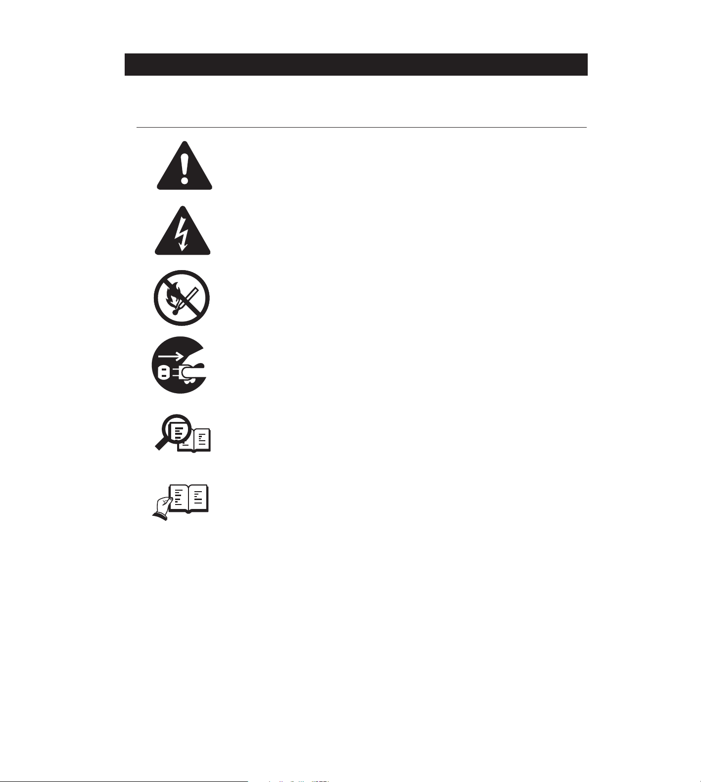
I. MEANING OF MARKS
The marks used in this manual have the following meanings.
Mark Meaning
States a precaution to be taken to prevent danger to personnel, damage to
the product, or damage to electronic components by discharge of static
electricity. for example.
States a precaution to be taken to prevent damage to electronic components
by electrostatic discharge.
Informs you of fire-related cautions.
Informs you that the plug must be removed from the power outlet before
starting an operation.
Gives useful information to understand descriptions.
Indicates sections to be read to obtain more detailed information.
I
NOTE
REFERENCE
Page 5

II. ABOUT THIS MANUAL
This manual is divided into five parts, and contains information required for servicing the
product.
Part 1: Facsimile
This section describes the facsimile function of the respective product.
Part 2: Printer
This section describes the printer function of the respective product.
Each of the above parts is further divided into the following four chapters:
Chapter 1: General Description
This part explains product specifications and the how to service the unit safely. It is very
important, so please read it.
Chapter 2: Technical Reference
This part explains the technical theory of the product.
Chapter 3: Maintenance and Service
This part explains how to maintain the products for adjustment and troubleshooting and
service operations and service switches.
Chapter 4: Appendix
This part explains the informations of the optional products and user data flow.
• For more details of user operations and user reports, see the separate volume
of
USER'S GUIDE
.
• Procedure for assembly/disassembly and greasing points are not given in this
manual. See the illustrations in the separate volume of
PARTS CATALOG
.
• Detailed description of each SSSW/parameter is not given in this manual
except the new SSSWs/parameters added to this model.
See
G3 Facsimile Service Data Handbook (supplied separately)
for details
them.
• See the
G3 Facsimile Error Code List (Rev.1, supplied separately)
for details of
the error codes not shown in this manual.
• Detailed description of connector Locations and Signal Descriptions in not
given in this manual.
See the
Circuit Diagram
for details them.
II
REFERENCE
Page 6

III. REVISION HISTORY
REVISION CONTENT
0 Original
III
Page 7

IV. TABLE OF CONTENTS
Part 1: Facsimile
Page
Chapter 1: General Description
1 - 1 1. FEATURES
1 - 1 1.1 Overview
1 - 2 2. SPECIFICATIONS
1 - 2 2.1 General Specification
1 - 2 2.2 Communication Specification
1 - 3 2.3 Scanner Specification
1 - 5 2.4 Printer Specification
1 - 7 2.5 Copy Specification
1 - 8 2.6 Function
1 -11 3. OVERVIEW
1 -11 3.1 External View
1 -14 3.2 Operation Panel
1 -17 3.3 Consumables
1 -17 3.3.1 BJ cartridge and ink cartridge and BJ cartridge container
1 -19 3.3.2 Print media
1 -21 4. DIMENSIONS
1 -22 5. SAFETY & PRECAUTIONS
1 -22 5.1 Personal Hazards
1 -24 5.1.1 Electrical shock
1 -24 5.1.2 High-temperature parts
1 -25 5.1.3 Fire hazards
1 -25 5.1.4 Moving parts
1 -25 5.1.5 Preventing ink stains
1 -26 5.2 General Cautions
1 -26 5.2.1 Unit cautions
1 -31 5.2.2 BJ cartridge cautions
1 -39 5.2.3 Ink cartridge cautions
1 -41 5.3 Servicing Cautions
1 -41 5.3.1 Damage from static charge
1 -41 5.3.2 Scanner unit
1 -42 5.3.3 Print assembly
1 -44 5.3.4 Paper feed section
1 -44 5.3.5 Control boards
1 -45 5.3.6 Opening the upper cover
1 -46 5.4 Data-related precautions
1 -47 5.4.1 Data in the image storage memory (DRAM)
1 -48 5.4.2 Data in the control processing memory (SRAM)
1 -49 5.4.3 Data in the EEPROM
1 -51 5.4.4 SCNT board replacement precautions
IV
Page 8

1 -52 5.4.5 Data initialization through service operation
1 -53 5.5 Protective Mechanism
1 -53 5.5.1 Data battery backup function
1 -53 5.5.2 BJ cartridge maintenance features
1 -54 5.5.3 Heat protection mechanism
1 -54 5.5.4 Overcurrent protection
1 -55 5.5.5 Lightning protection
1 -55 5.5.6 Power leakage protection
1 -56 6. QUALIFICATION REQUIRED FOR INSTALLATION WORK
Chapter 2: Technical Reference
2 - 1 1. COMPONENT LAYOUT
2 - 3 2. SCANNER MECHANISM
2 - 8 3. PAPER SUPPLY MECHANISM
2 -13 4. PRINTER SECTION
2 -20 5. BJ CARTRIDGE
2 -20 5.1 Structure
2 -23 5.2 BJ Head Driver Block Diagram
2 -25 5.3 Printing Signal
2 -27 6. ELECTRIC CIRCUIT
2 -27 6.1 Component Block Diagram
2 -28 6.2 Circuit Board Components
2 -31 6.3 Flow of Image Signals
2 -33 7. COMMUNICATION SYSTEM OPERATIONS
2 -33 7.1 FAX/TEL Switching
2 -33 7.1.1 Settings
2 -33 7.1.2 Parameters
2 -34 7.2 Answering Machine Connection
2 -34 7.2.1 Settings
2 -34 7.2.2 Parameters
2 -35 8. NEW FUNCTION
Chapter 3: Maintenance & Service
3 - 1 1. MAINTENANCE LIST
3 - 1 1.1 Consumables
3 - 1 1.2 Cleaning
3 - 2 1.3 Periodic Inspection
3 - 2 1.4 Periodic Replacement Parts
3 - 2 1.5 Adjustment Items
3 - 3 1.6 General Tools
3 - 3 1.7 Special Tools
3 - 4 2. HOW TO CLEAN PARTS
3 - 4 2.1 Main Unit Outer Covers
V
Page 9

3 - 4 2.2 Separation Roller
3 - 4 2.3 Separation Guide
3 - 4 2.4 Glass Window (contact sensor)
3 - 4 2.5 Printer Platen
3 - 6 3. ADJUSTMENT
3 - 6 3.1 Shading Data Adjustment
3 - 7 3.2 Vertical Alignment Correction
3 -10 3.3 Head Gap Adjustment
3 -14 4. TROUBLESHOOTING
3 -14 4.1 Troubleshooting Index
3 -15 4.2 Errors Shown on the Display
3 -15 4.2.1 User error message
3 -19 4.2.2 Error codes
3 -26 4.3 Errors not Shown on the Display
3 -26 4.3.1 General errors
3 -27 4.3.2 Printing problem
3 -29 4.3.3 Scanning problem
3 -31 5. SERVICE SWITCHES
3 -31 5.1 Hardware Switches
3 -31 5.2 Service Data Setting
3 -31 5.2.1 Service data overview
3 -32 5.2.2 Service data registration/setting method
3 -33 5.2.3 Service data setting
3 -40 5.2.4 Explanation of service data
3 -41 5.2.5 New SSSW's/parameters added to this model
3 -43 6. TEST FUNCTIONS
3 -43 6.1 User Test Print Functions
3 -43 6.1.1 Nozzle check
3 -44 6.2 Service Test Functions
3 -44 6.2.1 Test mode overview
3 -45 6.2.2 Test mode flowchart
3 -46 6.2.3 D-RAM tests
3 -46 6.2.4 CS tests
3 -47 6.2.5 PRINT test
3 -49 6.2.6 Modem and NCU tests
3 -52 6.2.7 Faculty tests
3 -57 7. SERVICE REPORT
3 -57 7.1 Report Output Function
3 -57 7.1.1 User report output functions
3 -59 7.1.2 Service report output functions
3 -67 8. WIRING DIAGRAM
3 -67 8.1 Wiring Diagram
3 -68 8.2 Connector Name and Signal Descriptions
VI
Page 10

Chapter 4: Appendix
4 - 1 1. INSTALLATION
4 - 1 1.1 Setting Up
4 - 1 1.2 Checking Operations
4 - 2 2. USER DATA FLOW
4 - 2 2.1 USER DATA FLOW (by Operation Panel)
4 - 3 2.2 USER DATA FLOW (by MultiPASS Desktop Manager)
4 - 8 2.3 SPECIAL MODE FLOW (by Operation Panel)
4 -10 4. MAKER CODE
INDEX
VII
Page 11

Part 2: Printer
Chapter 1: General Description
1 - 1 1. FEATURES
1 - 2 2. SPECIFICATIONS
1 - 2 2.1 Basic Specifications
1 - 5 2.2 Interface Specifications
1 -10 3. OVERVIEW
1 -10 3.1 Interface Connector
1 -11 3.2 Printer Operation Panel
1 -12 4. SAFETY & PRECAUTIONS
1 -12 4.1 Personal Hazards
1 -12 4.2 General Cautions
1 -12 4.2.1 Connecting the interface cable
1 -12 4.2.2 Data lost when power cord is pulled out
1 -12 4.2.3 Data reset
1 -13 5. RESTRICTIONS
Chapter 2: Technical Reference
2 - 1 1. THEORY OF OPERATIONS
2 - 1 2.1 Outline
2 - 2 2.2 Mechanical Overview
2 - 3 2.3 Data Flow
2 - 4 2.4 Printing
2 - 5 2.5 Circuit Overview
2 - 5 2.5.1 Printer circuit
2 - 7 2.6 720 dpi Printing/Smoothing Feature
2 - 7 2.6.1 Canon extension mode
2 - 7 2.6.2 Emulation mode
2 - 8 2.7 Printing Modes
2 - 8 2.7.1 Printing mode
2 - 8 2.7.2 Photoprint mode
2 -10 2.8 Optimum Printing Direction Control
2 -10 2.9 Ink Smear Control
2 -11 2.10 Bi-Centronics Interface
2 -11 2.10.1Functions
2 -12 2.10.2Structure
Chapter 3: Maintenance & Service
3 - 1 1. MAINTENANCE LIST
3 - 1 2. HOW TO CLEAN PARTS
3 - 1 3. ADJUSTMENT
3 - 2 4. TROUBLESHOOTING
3 - 2 4.1 Errors Shown on the Display
VIII
Page 12

3 - 2 4.1.1 User error message
3 - 2 4.1.2 Error codes
3 - 3 4.2 Errors not Shown on the Display
3 - 5 5. SERVICE OPERATION FUNCTION
3 - 5 5.1 Report Output Function
3 - 5 5.2 Service Data
3 - 5 5.3 Test Functions
3 - 5 5.3.1 User test functions
3 - 6 5.3.2 Hexadecimal dump list
3 - 7 6. WIRING DIAGRAM
3 - 7 6.1 Wiring Diagram
3 - 7 6.2 Connector Location and Signal Description
3 - 7 6.2.1 SCNT board
Chapter 4: Appendix
4 - 1 1. INSTALLATION
4 - 2 1.1 Choosing a Location for Printer
4 - 3 1.2 Connecting the Printer to the Computer
IX
Page 13

V. ILLUSTRATION INDEX
Part 1: Facsimile
Page
Chapter 1: General Description
1 - 4 Figure 1- 1 Scanning Range
1 - 6 Figure 1- 2 Printing Range
1 -11 Figure 1- 3 External View (1)
1 -12 Figure 1- 4 External View (2)
1 -14 Figure 1- 5 Operation Panel (1)
1 -15 Figure 1- 6 Operation Panel (2)
1 -16 Figure 1- 7 Operation Panel (3)
1 -17 Figure 1- 8 Consumables (1)
1 -18 Figure 1- 9 Consumables (2)
1 -19 Figure 1-10 Print Media (1)
1 -20 Figure 1-11 Print Media (2)
1 -21 Figure 1-12 Dimensions
1 -22 Figure 1-13 Personnel Hazards (1)
1 -23 Figure 1-14 Personnel Hazards (2)
1 -37 Figure 1-15 Unpacking the BJ Cartridge
1 -38 Figure 1-16 Ink Path Cartridge
1 -39 Figure 1-17 Removing Cartridge Cap
1 -40 Figure 1-18 Ink Outlet
1 -42 Figure 1-19 Print Assembly Precautions
1 -45 Figure 1-20 Opening the Upper Cover
1 -46 Figure 1-21 Memory IC and Backed up Devices
1 -50 Figure 1-22 Waste Ink Absorber
1 -52 Figure 1-23 All Clear
Chapter 2: Technical Reference
2 - 1 Figure 2- 1 Mechanical Layout
2 - 2 Figure 2- 2 Electrical System Layout
2 - 3 Figure 2- 3 Document Feed Section
2 - 5 Figure 2- 4 Document Separation
2 - 7 Figure 2- 5 Contact Sensor
2 - 8 Figure 2- 6 Paper Feed Section
2 -10 Figure 2- 7 Paper Feed Motor Drive Switching
2 -11 Figure 2- 8 Paper Separation Mechanism
2 -13 Figure 2- 9 Printer Section
2 -15 Figure 2-10 Purge Unit
2 -15 Figure 2-11 Pump Operation State Detection
2 -18 Figure 2-12 Ink Empty Detection
2 -20 Figure 2-13 Nozzle Arrangement
2 -21 Figure 2-14 Black BJ Cartridge Structure
X
Page 14

2 -21 Figure 2-15 Color BJ Cartridge Structure
2 -22 Figure 2-16 Photo BJ Cartridge Structure
2 -24 Figure 2-17 BJ Head Driver Block Diagram (Black BJ Cartridge)
2 -24 Figure 2-18 BJ Head Driver Block Diagram (Color BJ Cartridge)
2 -25 Figure 2-19 Printing Sequence (Black BJ Cartridge/HQ Mode)
2 -26 Figure 2-20 Printing Signals (HQ Mode)
2 -27 Figure 2-21 Block Diagram
2 -31 Figure 2-22 G3 Transmission Image Signal Flow
2 -32 Figure 2-23 G3 Reception Image Signal Flow
Chapter 3: Maintenance & Service
3 - 5 Figure 3- 1 Cleaning Location
3 - 6 Figure 3- 2 Shading Data Adjustment Operation 1
3 - 6 Figure 3- 3 Shading Data Adjustment Operation 2
3 - 7 Figure 3- 4 Printing the Test Pattern
3 - 7 Figure 3- 5 Test Pattern Sample
3 - 8 Figure 3- 6 Correct Test Pattern
3 - 8 Figure 3- 7 Sample Test Pattern with Vertical Misalignment
3 - 9 Figure 3- 8 Vertical Line Misalignment Correction Procedure
3 -10 Figure 3- 9 Headgap
3 -11 Figure 3-10 Adjustment Preparation
3 -12 Figure 3-11 Head Gap Adjustment (1)
3 -13 Figure 3-12 Head Gap Adjustment (2)
3 -19 Figure 3-13 Service Error Code Display
3 -27 Figure 3-14 Paper Feed Motor/Carriage Motor/Document Feed Motor Connector
3 -28 Figure 3-15 Defective Pattern (Sample)
3 -32 Figure 3-16 Service Data Setting Method
3 -33 Figure 3-17 Service Data (page 1)
3 -34 Figure 3-18 Service Data (page 2)
3 -35 Figure 3-19 Service Data (page 3)
3 -37 Figure 3-20 Service Data (page 4)
3 -38 Figure 3-21 Service Data (page 5)
3 -39 Figure 3-22 Service Data (page 6)
3 -40 Figure 3-23 Bit Switch Display
3 -40 Figure 3-24 How to Read Bit Switch Tables
3 -43 Figure 3-25 Nozzle Check Pattern
3 -45 Figure 3-26 Test Mode
3 -46 Figure 3-27 D-RAM Test
3 -47 Figure 3-28 Print Test Pattern Check
3 -48 Figure 3-29 Print Pattern Sample
3 -51 Figure 3-30 CNG and DTMF Signal Reception Tests
3 -53 Figure 3-31 Sensor Tests
3 -55 Figure 3-32 Operation Panel
XI
Page 15

3 -58 Figure 3-33 Memory Clear List
3 -60 Figure 3-34 System Data List (page 1 ~ page 4)
3 -61 Figure 3-35 System Data List (page 5 ~ page 6)
3 -62 Figure 3-36 System Dump List (1/2)
3 -64 Figure 3-37 System Dump List (2/2)
3 -65 Figure 3-38 Service Error Tx Report
3 -66 Figure 3-39 Service Error Activity Report (receiving)
3 -67 Figure 3-40 Wiring Diagram
Chapter 4: Appendix
4 - 2 Figure 4- 1 User Menu Settings (1/6)
4 - 3 Figure 4- 2 User Menu Settings (2/6)
4 - 4 Figure 4- 3 User Menu Settings (3/6)
4 - 5 Figure 4- 4 User Menu Settings (4/6)
4 - 6 Figure 4- 5 User Menu Settings (5/6)
4 - 7 Figure 4- 6 User Menu Settings (6/6)
4 - 8 Figure 4- 7 Special Mode Settings
4 -10 Figure 4- 8 Maker Code
XII
Page 16

Part 2: Printer
Page
Chapter 1: General Description
1 - 4 Figure 1- 1 Printing Range
1 - 6 Figure 1- 2 Signal Circuits
1 - 9 Figure 1- 3 Interface Timing
1 -10 Figure 1- 4 Interface Connector
Chapter 2: Technical Reference
2 - 1 Figure 2- 1 Printer Outline
2 - 3 Figure 2- 2 Data Flow (image)
2 - 4 Figure 2- 3 Character Printing
2 - 5 Figure 2- 4 Printer Circuit Block Diagram
2 - 7 Figure 2- 5 720 dpi Printing/Smoothing Feature
2 -13 Figure 2- 6 Nibble Mode Facsimile to Host Data Transfer
2 - 9 Table 2- 1 Printing Modes and Heating Method
Chapter 3: Maintenance & Service
3 - 6 Figure 3- 1 Hexadecimal Dump Print (Sample)
3 - 7 Figure 3- 3 SCNT Board
Chapter 4: Appendix
4 - 2 Figure 4- 1 Location for the Printer
4 - 3 Figure 4- 2 Connecting the Interface Cable
XIII
Page 17

MultiPASS C3000
Service Manual
Part 1: Facsimile
Page 18

1. FEATURES
1.1 Overview
This product is a G3 transreceiving facsimile based on the ITU-T recommendation. It can
be used in telephone networks.
*: This mark indicates new function.
Excellent print quality
The high-performance print head offers 360 × 360 dot per inch (dpi) resolution for text and
graphics.
Automatic switching between fax and voice calls
Fax/telephone switching allows you to receive fax messages and normal phone calls on a
single line.
BJ cartridge REFER TO PAGE 2-20.
The BC-20 and BC-21 BJ cartridges provide excellent print quality for crisp, clean-looking
documents.
Convenient paper handling
The paper tray holds up to 100 sheets of plain letter, legal, or A4 paper, and the automatic
document feeder can hold up to 20 letter-size, A4-size or 10 legal-size pages.
Simple maintenance
The replaceable ink cartridge contains the ink and the print head. When it runs out of ink,
simply replace it.
Ink detection function REFER TO PAGE 2-18.
This model has a new ink detection function. After each received page is printed, ink is
ejected in front of a photosensor, so that the machine can detect whether there is ink
remaining or not.
Chapter 1: General Description
1-1
Page 19

2. SPECIFICATIONS
2.1.General Specification
Type Desktop
Body colour Art gray
Power source 98 ~ 132V AC, 48 ~ 62 Hz,
Power consumption standby 6.5W / Max. 47 W (when 100% black copy)
Usage environment. 50.0°F ~ 90.5°F (10°C ~ 32.5°C), 20%~85% RH, 532 ~ 760
mmHg (709 ~ 1013 hPa)
Horizontal ±3° or less
Operating noise Measured in accordance with ISO standards
Standby :35 dB(A) or less
Operating :47dB(A) or less
Dimensions (W ✕ D ✕ H) 15.75" × 14.2" × 7.75" (400 mm × 361 × 197 mm)
(Not including Trays)
Weight 13.23 lbs (6.0 kg) Including trays
2.2 Communication Specification
Applicable lines PSTN (Public Switched Telephone Network)
PBX (Private Branch eXchange)
Applicable Services DRPD
Handset None
Transmission method Half-duplex
Transmission control protocol ITU-T T30 binary protocol/ECM protocol
Modulation method
G3 image signals ITU-T V.27ter (2.4k, 4.8k bps)
ITU-T V.29 (7.2k, 9.6k bps)
ITU-T V.33 (12k, 14.4k bps)
ITU-T V.17 (TC7.2k, TC9.6k, 12k, 14.4k bps)
G3 procedure signals ITU-T V.21 (No.2) (300bps)
(With automatic fallback function)
Coding ITU-T T.4 Coding method (MH, MR)
ITU-T T.6 Coding method (MMR)
Error correction ITU-T T30 (ECM)
Canon express protocol (CEP) None
Part 1: Facsimile
1-2
Page 20

Time required for transmission protocol
Pre-message Post-message Post-message
Protocol *
1
Protocol *
2
Protocol *
3
Mode (between pages) (after pages)
Standard/Fine approx.12 sec. approx.4 sec. approx.3.5 sec.
*1 Time from when other facsimile is connected to the line until image transmission begins.
*2 Post-message (between pages): Time from after one document has been sent until
transmission of the next document starts if several pages are transmitted.
*3 Post-message (after last pages): Time from after image transmission is completed until
line is switched from facsimile to telephone.
Minimum transmission time 10 msec (MH,MR), 0 msec (MMR)
Transmission output level from 0 to -15 dBm
Receive input level from -3 to -43 dBm
Modem IC R144EFXL
2.3 Scanner Specification
Type Sheets
ADF capacity Max. 20 sheets (A4/Letter)
Max. 10 sheets (Legal)
Effective scanning width Letter/Legal 8.42" (214 mm)
A4 8.19" (208 mm)
Scanning method Contact sensor scanning method
Scanning line density
Horizontal: 8 dot/mm (203.2 dpi)
Vertical: Standard 3.85 line/mm (97.79 dpi)
Fine 7.7 line/mm (195.58 dpi)
Scanning speed Binary (200 dpi) 10 msec./line
Binary (300, 400 dpi) 5 msec./line
256 gray scales (200 dpi) 10 msec./line
256 gray scales (300, 400 dpi) 20 msec./line
Scanner gray scales 8 bit, 256 gray scales
TWAIN Yes
Image modes Halftone (PHOTO mode)
Scanning density adjustment 3 density level (PC assisted)
Halftone (fax and copy) 64-gradation error diffusion system (UHQ-6.5)
Prescan None
Chapter 1: General Description
1-3
Page 21

Scanning range
Sheet dimensions (W × L)
Maximum 8.50" × 39.3" (216 mm × 1000 mm)
Minimum 3.5" × 2.5" (88.9 mm × 63.5 mm)
Thickness
multiple pages: 0.002" ~ 0.005" (0.06 mm ~ 0.13 mm)
40~90 g/m2
Item A4 Letter Legal
➀ Effective scanning width 8.09"~8.18" 8.33"~8.42" 8.33"~8.42"
(205.5~208 mm) (211.5~214 mm) (211.5~214 mm)
➁ Effective scanning length 11.54" 10.84" 13.84"
(290.0~296 mm) (272.4~278.4 mm) (348.6~354.6 mm)
➂ Left margin 0.04" ±0.14" 0.08" ±0.14" 0.08" ±0.14"
(1.0 mm ±3.5 mm) (2.0 mm ±3.5 mm) (2.0 mm ±3.5 mm)
➃ Right margin 0.04" ±0.14" 0.04" ±0.14" 0.04" ±0.14"
(1.0 mm ±3.5 mm) (1.0 mm ±3.5 mm) (1.0 mm ±3.5 mm)
➄ Top margin 0.08" ±0.08" 0.08" ±0.08" 0.08" ±0.08"
(2.0 mm ±2.0 mm) (2.0 mm ±2.0 mm) (2.0 mm ±2.0 mm)
➅ Bottom margin 0.08" ±0.08" 0.08" ±0.08" 0.08" ±0.08"
(2.0 mm ±2.0 mm) (2.0 mm ±2.0 mm) (2.0 mm ±2.0 mm)
Units are inches with mm shown in parentheses.
Document scanning width “A4/LTR” is set in service data #1 SSSW SW06,
bit4.
Part 1: Facsimile
1-4
Figure 1-1 Scanning Range
NOTE
Document leading edge
➀
➃➂
SCANNING
DROP OUT RANGE
SCANNING RANGE
Document trailing edge
➄
➁
➅
Page 22

2.4 Printer Specification
Printing method Bubble-jet ink on-demand
BJ Cartridge
Products name BC-20 Black BJ cartridge/BC-21 Color BJ cartridge/BC-22
Photo Color BJ cartridge
Product code F45-0561/F45-0571/F45-1141
Print head 128 nozzles/136 nozzles (Y:24, M:24, C:24, Bk:64)/136 nozzles
Ink cartridge (Ink tank) None/BCI-21 Color or BCI-21 Black/None
Valid period 1 year/half a year (since the seal was opened)/1 year
Storage conditions Temperature 32.0°F ~ 95.0°F (0°C ~ 35°C)
Humidity35% ~ 85% RH
Ink Cartridge
Products name BCI-21 Black Ink Cartridge/BCI-21 Color Ink Cartridge
Product code F47-0731/F47-0741
Ink contains 9 ml/5 ml each of YMC
Ink detection Yes (Directly detects ink ejection )
Printing speed Approx. 5 pages/minute (in case of character print)
Printing resolution 360 dpi × 360 dpi (Normal print)
180 dpi × 180 dpi (Economy print*)
*Printing in a checkered pattern without printing vertical and horizontal adjacent dots.
Paper output tray stacking Approx. 50 sheets (when using the recommended paper)
Approx. 20 sheets (when raised output guides)
Paper tray
Paper supply method ASF (Auto Sheet Feeder)
Number of paper tray 1tray : Legal/Letter/A4 (Universal )
Paper capacity Max. 0.40" (10 mm) thickness
plain paper (Approx. 100 sheets)
Recommended paper
Canon Copier LTR/LGL Premium Paper
Weight 75 g/m
2
Paper size Letter, Legal
Manufactured by BOISE CASCADE
PLOVER BOND
Weight 75 g/m2, 90 g/m
2
Paper size Letter
Manufactured by FOX RIVER
XEROX 4024
Weight 75 g/m2, 90 g/m
2
Paper size Letter, Legal
Manufactured by XEROX
Chapter 1: General Description
1-5
Page 23

Printing range
Paper dimensions (W × L)
Letter 8.50" × 10.98" (216 mm × 279 mm)
Legal 8.50" × 14.02" (216 mm × 356 mm)
A4 8.27" × 11.69" (210 mm × 297 mm)
Item A4 Letter Legal
➀ Effective printing width 8.00"±0.12" 8.00"±0.12" 8.00"±0.12"
(203.2±3.0" mm) (203.2±3.0" mm) (203.2±3.0" mm)
➁ Effective printing length 11.20" 10.51" 13.47"
(287±3 mm) (269.4±3 mm) (345.6±3.5 mm)
➂ Left margin 0.13"±0.06" 0.25"±0.06" 0.25"±0.06"
(3.4±1.5 mm) (4.9±1.5 mm) (4.9±1.5 mm)
➃ Right margin 0.13"±0.06" 0.25"±0.06" 0.25"±0.06"
(3.4±1.5 mm) (4.9±1.5 mm) (4.9±1.5 mm)
➄ Top margin 0.12"±0.06" 0.12"±0.06" 0.12"±0.06"
(3.0±1.5 mm) (3.0±1.5 mm) (3.0±1.5 mm)
➅ Bottom margin 0.27"±0.12" 0.27"±0.12" 0.27"±0.12"
(7.0±3.0 mm) (7.0±3.0 mm) (7.0±3.0 mm)
Units are inches with mm shown in parentheses.
•The header and footer are printed in the printing range.
•The shaded area is included in the left and right margin errors of
the paper trailing edge.
•➁, ➄, ➅ represent the vertical direction printing drop out range,
and printing range 0.71" (18mm) or less.
•The printing range is set in user data "FAX PRINTER SETTING", "SELECT
PAPER SIZE".
Part 1: Facsimile
1-6
Figure 1-2 Printing Range
Paper leading edge
➀
➃➂
PRINTING DROP OUT RANGE
PRINTING RANGE
Paper trailing edge
➄
➁
➅
NOTE
Page 24

2.5 Copy Specifications
Color copy None
Multiple copy 99 copies
Copy resolution
Scanning 360 dpi × 360 dpi (direct copy)
8 dot/mm × 7.7 line/mm (memory COPY)
(UHQ-6 smoothing)
Printing 360 dpi × 360 dpi
Copy magnification ratio 100%, 90%, 80%, 70%
Chapter 1: General Description
1-7
Page 25

2.6 Function
Dialling
Manual dialling Numeric button
Auto dialing Max. 120 digits
One-touch:6, Coded speed:50, Numeric button:1
Group dial Max.55 locations
Redial Numeric button redial function (Max. 120 digits)
Transmission
Broadcast transmission Max. 57 locations (One-touch:6, Coded speed:50, Numeric
button:1)
Delayed transmission Yes (PC Assisted)
Confidential Tx/Rx None
Relay broadcasting originating None
Relay broadcasting None
Reception
Dual Access Yes
FAX/TEL switching Yes
Method CNG, ROT(Re-Order Tone) detection
Message None
Pseudo CI None
Pseudo ring Yes
Pseudo ringback tone Yes
Reduction settings for reception Yes
Automatic reduction of reception images Yes (100%~70%)
Built-in Answering machine None
Answering machine connection Yes (Telephone answering priority type)
Remote reception Yes (Remote ID method)
Memory lock reception None
Reception printing in reverse order None
Polling
Polling transmission None
Polling reception None
Part 1: Facsimile
1-8
Page 26

Others
Closed network None
Direct mail prevention None
Reception printing in reverse order None
Memory box None
Memory backup
Backup contents Dial registration data, User data, Service data,
Time
Backup IC 256 kbit SRAM for control
Backup device Lithium battery 3.0V DC/560 mAh
Battery life Approx.. 5 years
Image data backup None
Activity management Yes
a) User report
Activity management report (Every 20 transactions : always transmission and reception
together)
Activity report (sending/receiving)
One-touch speed dialling list (by SPECIAL MODE)
Coded speed dialling list (by SPECIAL MODE)
Group dialling list (by SPECIAL MODE)
Memory clear list
User’s data list (by SPECIAL MODE)
Multi activity report
b) Service report
System data list
System dump list
Error list
Chapter 1: General Description
1-9
Page 27

Transmitting terminal identification Yes
Time
Management data Year/month/date/day/hour/minute (24 hour
display)
Precision ±30 sec per month
Display 1row × 16 digits
Completion stamp None
Program key None
Telephone exchange function None
Speaker phone None
Demo print function None
HELP function None
Part 1: Facsimile
1-10
Page 28
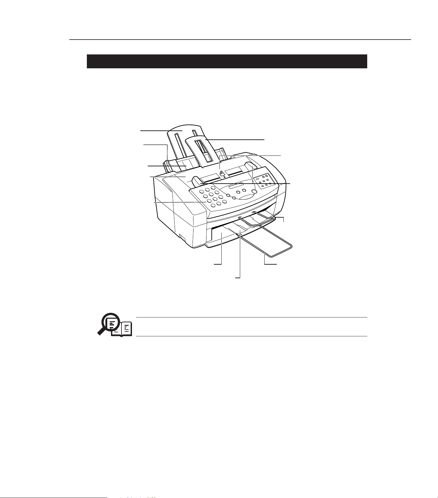
3. OVERVIEW
3.1 External View
For the switches used for servicing, refer to
Chapter 3: 5.1 Hardware Switches on
Page 3-31
.
Chapter 1: General Description
1-11
Front View
OPERATION PANEL
PRINTER COVER
AUTOMATIC DOCUMENT
FEEDER (ADF)
SENDING DOCUMENT SUPPORT
DOCUMENT SUPPORT FOR
SCANNED DOCUMENTS
OUTPUT TRA Y EXTENSIONOUTPUT TRA Y
SHEET FEEDER
PAPER GUIDE
PAPER OUTPUT GUIDES
PAPER REST
DOCUMENT GUIDES
Figure 1-3 External View (1)
NOTE
Page 29
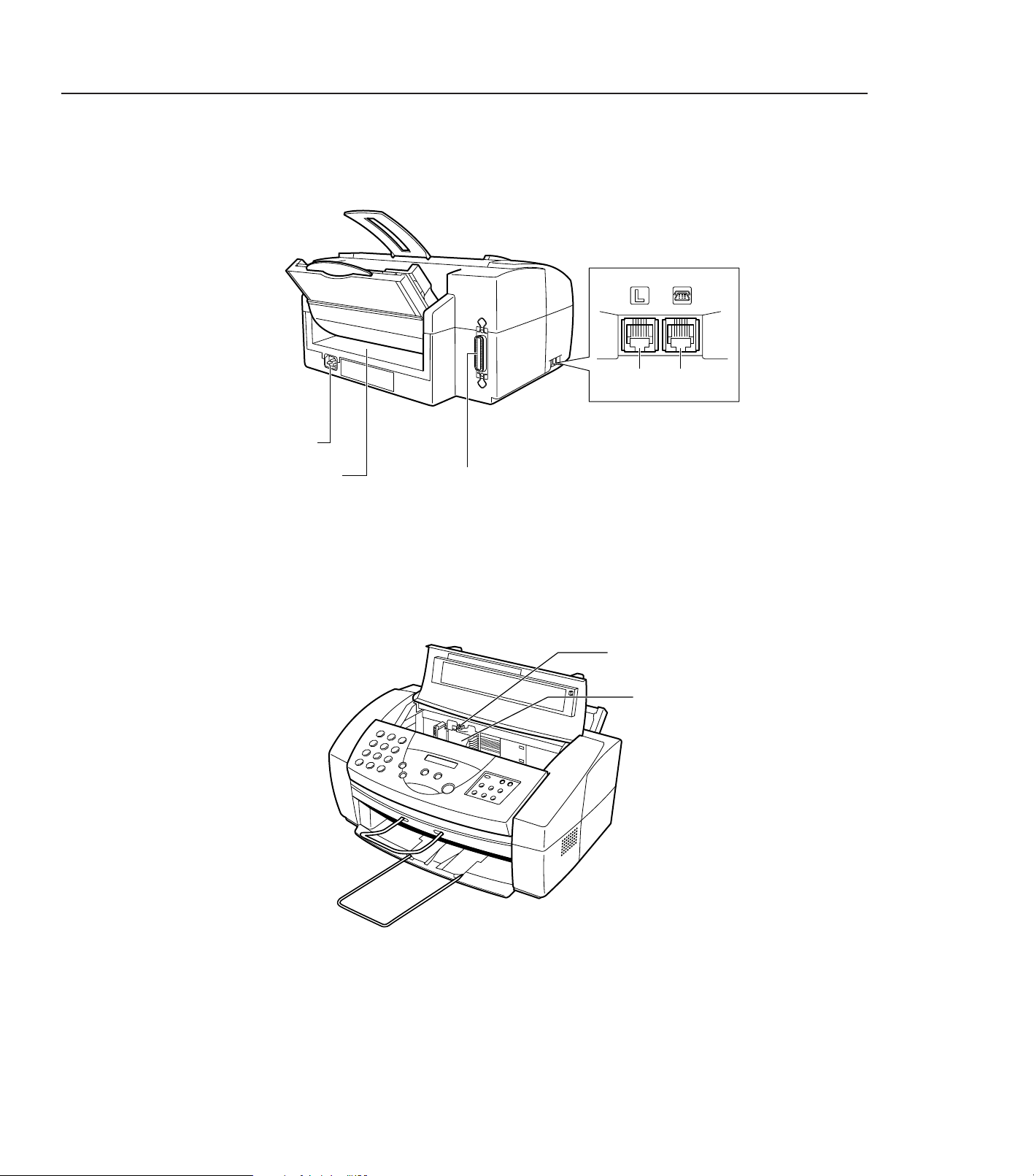
Part 1: Facsimile
1-12
Rear View
BI-DIRECTIONAL PARALLEL PORT
MANUAL FEEDER
POWER
CONNECTOR
TELEPHONE
LINE JACK
EXTENSION
PHONE JACK
Figure 1-4 External View (2)
Inside the Printer Cover
P APER THICKNESS LEVER
CARTRIDGE HOLDER
Page 30

Chapter 1: General Description
1-13
This page intentionally left blank
Page 31

3.2 Operation Panel
Part 1: Facsimile
1-14
The C3000’s Controls — The Operation Panel
u RECEIVE MODE button
Use this button to select whether the C3000 is set to receive faxes
manually (“Manual Mode”), to treat all calls as faxes (“Fax Only Mode”),
to use an answering machine to receive all calls (“Ans.Machine Mode”),
or to automatically switch between telephone and fax receiving,
depending on the type of call (“Fax/Tel Mode”).
v LCD display
This displays messages and prompts during operation, and displays
selections, text, numbers, and names when registering information.
w One-Touch Speed Dial/Special Function buttons
Use these for one-touch speed dialing, entering user information,
printing documents stored in memory, and cleaning the print head.
x RESOLUTION button
Press this to select the resolution the C3000 will use for the document
you want to fax or scan.
1 2
ABC3DEF
4 5
JKLGHI
6
MNO
7 8
TUVPRS
9
WXY
0
OPER
TONE
SYMBOLS
REDIAL/PAUSE RECEIVE MODE RESOLUTION
ALARM
STOP
CODED DIAL
START/COPY
123
456
PRINTER
RESET
CARTRIDGEFUNCTION RESUME
W NUMERIC BUTTONS
X REDIAL/PAUSE
at CODED DIAL
u RECEIVE MODE
ak START/COPY
x RESOLUTION
am STOP
an ARROW BUTTONS
ao PRINTER RESET
v LCD DISPLAY
al ALARM
y FUNCTION
U CARTRIDGE
V RESUME
w ONE-TOUCH SPEED DIAL/
SPECIAL FUNCTION BUTTONS
Figure 1-5 Operation Panel (1)
Page 32

Chapter 1: General Description
1-15
Figure 1-6 Operation Panel (2)
y FUNCTION button
Use this to enter user information, to run the C3000’s self-cleaning
process, check the nozzles, or to print faxes stored in the C3000’s
memory.
U CARTRIDGE button
Press this to release the C3000’s BJ cartridge holder to its center position
for installing or replacing the cartridge. (Press again after installing the
cartridge to return the cartridge holder back to its home position.)
V RESUME button
Press this when you want to form-feed paper when printing.
W Numeric buttons
Use these buttons to type numbers and names when entering
information, and to dial fax/telephone numbers that are not registered
for automatic dialing.
X REDIAL/PAUSE button
Press this to redial the last number that was dialed using the number
buttons, or to enter pauses between digits when dialing fax numbers.
at CODED DIAL button
Press this button (followed by entering a two-digit code with the number
buttons) to dial a fax number that you have registered for coded speed
dialing.
ak START/COPY button
Press this to begin sending, receiving, scanning, or other operations, or to
select functions when registering information.
al ALARM lamp
This flashes when an error occurs, when the C3000 is out of paper or ink,
or when received faxes are stored in memory.
amSTOP button
Press this to cancel sending, receiving, or any other operation.
an Arrow buttons (
<< >>
)
Use these to scroll through menu selections or to move the cursor when
registering data.
ao PRINTER RESET button
Press this to reset the C3000 if your PC crashes. This will maintain all the
faxes currently in memory. Do not unplug the C3000 to reset the unit or
the faxes in memory will be lost.
Page 33

Part 1: Facsimile
1-16
Entering a Name
When entering a name (such as “Unit Name”), each numeric button has
a number and a group of uppercase and lowercase letters assigned to it.
The chart below shows which number to press for each character.
Button Characters
11
2 ABCabc2
3 DEFdef3
4 GHIghi4
5 JKLjkl5
6 MNOmno6
7 PQRSpqrs7
8 TUVtuv8
9 WXYZwxyz9
00
# -.*#!”,;:^`_=/|’?$@%&+()[]{}<>
Figure 1-7 Operation Panel (3)
Page 34

3.3 Consumables
3.3.1 BJ cartridge and ink cartridge and BJ cartridge container
Chapter 1: General Description
1-17
Choosing the Best Cartridge
Canon offers several BJ print cartridges and ink tanks for use in the
C3000. (BJ print cartridges contain the BJ print head and ink, while BJ
ink tanks contain only ink.) Use the following descriptions to decide
which type of cartridge best suits your particular needs.
N
To avoid printing problems, use only the BC-21 BJ cartridge for normal
printing (or the separately sold BC-20 Black BJ cartridge, if you rarely
print color). The BC-22 Photo Color BJ Cartridge (sold separately) is for
printing photo-realistic color images. Other cartridges can produce
unsatisfactory results. In addition, use only BCI-21 Black and BCI-21
Color ink tanks in the BC-21 Color BJ cartridge.
BC-21 Color BJ Cartridge
The BC-21 incorporates a BJ print head and
two replaceable ink tanks (a BCI-21 Black
and a BCI-21 Color). Use this cartridge for
normal printing.
BCI-21 Black ink tank
Purchase this ink tank from your local
Canon dealer as the black ink runs out of the
BC-21 Color BJ cartridge.
BCI-21 Color ink tank
Purchase this ink tank from your local
Canon dealer as the color ink runs out of the
BC-21 Color BJ cartridge.
BC-20 Black BJ Cartridge
This cartridge incorporates a BJ print head
and black ink in a single unit. The BC-20 can
be used if most of your printing is black, e.g.
for receiving faxes, making copies, and
monochrome printing. It can print twice as
fast as a color cartridge, and at higher
resolution.
Ink
Cartridge
BCl-21
Made in
Japan
Color
Ink
Cartridge
BCl-21
Made in
Japan
Black
Made in Japan
Color BJ
Cartridge
BC-21
Ink
Cartridge
BCl-21
Made in
Japan
Black
Ink
Cartridge
Made in
Japan
BCl-21
Color
Figure 1-8 Consumables (1)
Page 35

Part 1: Facsimile
1-18
BC-22 Photo Color BJ Cartridge
Includes the print head and color ink in a
single unit. Use this cartridge for printing
photo-realistic color images.
N
The C3000 cannot print incoming faxes or make copies while the BC-22
cartridge is installed. This is an ink-saving feature: because the BC-22 is
a single unit (and does not have ink tanks that can be replaced
separately), using it to print faxes will use the black ink faster, using up
the cartridge while it still has a considerable amount of color ink
remaining.
SB-21 BJ Cartridge Container
Use the SB-21 to store an extra BJ cartridge
in a convenient location, while keeping it
from drying out.
N
Your C3000 unit comes with a BC-21 Color BJ Cartridge (which
incorporates the BCI-21 Black and BCI-21 Color ink tanks) and an
additional BCI-21 Black ink tank. When you run out of ink, or if you
wish to use any other Canon BJ cartridges mentioned above, you can
purchase them from a Canon Official Dealer.
Figure 1-9 Consumables (2)
Page 36

3.3.2 Print media
Chapter 1: General Description
1-19
Plain Media
Plain paper
The C3000 produces letter-quality print on most plain bond paper,
including cotton bond and photocopy paper. It can use A4, letter, or
legal sizes. The paper must be less than 0.008 inch (0.2 mm) thick, and
have a weight of 17–24 lbs (64–90 g/m2).
N
You can also use paper weighing 24–28 lbs (90–105 g/m2) by manually
feeding sheets, one at a time.
Envelopes
The C3000 can print on U.S. Commercial No. 10 (9.5 x 4.1 inches) and
European DL (220 x 110 mm) envelopes.
Figure 1-10 Print Media (1)
Canon Media
Canon provides the following media, all specifically developed to
extend the printing capability of your C3000. For details or purchase,
contact your local authorized Canon dealer.
Canon Bubble Jet Paper LC-301 (water resistant)
This is a water-resistant, letter-size paper specially developed for color
printing with Canon Color BJ printers such as the C3000. Images printed
on LC-301 paper are bright and vivid, and will not run if liquid is spilled
on them. Images printed on this paper stand up to normal office
highlighters, unlike images printed on other papers.
Canon High-Resolution Paper HR-101
This paper is designed to produce near-photographic quality print
output, with sharp, vivid graphics and photographs. You must use this
paper when printing with the BC-22 Photo Color BJ Cartridge. When
using HR-101 paper, be sure to print on the whiter side of the sheets,
and after printing a pack of this paper, use the cleaning sheet provided
with it to clean the printer roller.
Canon Transparencies CF-102
These letter-size overhead transparencies are specially designed for
Canon BJ color printers. Use these clear transparencies to produce crisp
and professional overhead presentations. Do not use normal
transparencies in the C3000, as they do not absorb ink and can cause the
ink to run.
Canon Back Print Film BF-102
This unique mylar-based translucent sheet allows you to print highquality letter-size color output — including photographs and graphics
— that you can view with a rear illumination device such as with a light
box. This gives you sharp, bright, vivid images you can use in meetings,
trade shows, and other presentations.
N
If you are printing from an application outside Windows, your
application or printer driver must support mirror image printing in
order to use back print film.
Page 37

Part 1: Facsimile
1-20
Canon High-Gloss Film HG-101
This is a high-grade, letter-size gloss film that lets you create sharper
and more vivid color output than is possible with coated paper. This
film provides the best color print quality for the BC-21 Color BJ
cartridge. Use this film for trade show displays or other special
presentations, and when printing at 720 x 360 dpi resolution.
Fabric Sheets FS-101
These legal-size, white, cotton fabric sheets are specifically designed for
Canon BJ Color printers, and enable you to print your own designs for
cross stitch, pillows, holiday stockings, and other craft projects.
T-Shirt Transfers TR-101
This special letter-size sheet allows you to print your own designs and
transfer them to any cotton or cotton/poly blend t-shirt, sweatshirt,
apron, tote bag, or other fabric item.
N
Be sure to select Back Print Film Option when printing on the TR-101 TShirt Transfers. See the MultiPASS Desktop Manager for Windows®User’s
Guide for instructions.
Figure 1-11 Print Media (2)
Page 38

4. DIMENSIONS
Chapter 1: General Description
1-21
400
618
361198 59
197 84
281
Units : mm
Figure 1-12 Dimensions
Page 39

5. SAFETY & PRECAUTIONS
5.1 Personnel Hazards
Part 1: Facsimile
1-22
SCNT board
Page 1-24
Power supply unit (~185˚F)
Page 1-24
Litium battery
Page 1-25
Electrical Shock and High-Temprature Parts
Fire hazards parts
Telephone line
Page 1-24
PCNT board (~173.1˚F)
Page 1-24
Carriage motor (~145.2˚F)
Page 1-24
Paper feed motor (~132˚F)
Page 1-24
Document feed motor (~113˚F)
Page1-24
BJ cartridge (~212˚F)
(Alminium plate)
PAGE 1-24
Figure 1-13 Personnel Hazards (1)
Page 40

Chapter 1: General Description
1-23
Separation roller
Transmission roller
Document eject
roller
Document feed
roller
Document pinch
roller
Document feed
motor
Paper eject roller
Paper feed motor
Carriage motor
Carriage belt
Transmission roller
Pickup roller
Lifting plate
Purge unit
Ink absorber
Paper feed roller
Moving parts ☞ Page1-25
Preventing ink stains ☞ Page1-25
Figure 1-14 Personnel Hazards (2)
Page 41

5.1.1 Electrical shock
Electrical shock hazard
•To prevent electrical shock, be sure to disconnect the power cord and modular
jack before disassembly.
•Remove grounding wrist straps before servicing this unit while the FAX’s
power is on. Otherwise, electrical shock may occur.
Power supply unit
When power is supplied to this unit, 120 VAC will be supplied to the primary
side.
Telephone line
If a telephone line is connected to this unit, 48 VDC will be supplied by this
line. When a call signal is received, a voltage of 90 VAC Vrms will be
supplied.
5.1.2 High-temperature parts
High-temperature warning
To prevent skin burns, disconnect the power cord and let this unit stand for
at least 10 minutes to allow hot parts to cool.
How to treat burns
Heat of about 122°F or more causes burns. Also, the longer the contact, the
more severe the burn.
When treating a burn, the first minute after receiving the burn is the most
important. Cool the burn immediately with cold running water. In case of a
serious burn, seek medical attention immediately.
The parts which get hot during operation are indicated. For the location of
these parts, refer to the figures.
(Ambient temperature 95°F (35°C) continuous copy operation)
Document feed motor (approx. ~ 113.9°F (45.5°C))
Paper feed motor (approx. ~ 132°F (55.6°C))
Carriage motor (approx. ~ 145.2°F (62.9°C))
Power supply unit (Max. ~ 185°F (85.2°C))
PCNT board assembly (approx. ~ 173.1°F (78.4°C))
BJ cartridge (max. ~ 212°F (100°C))
Part 1: Facsimile
1-24
NOTE
NOTE
NOTE
Page 42

5.1.3 Fire hazards
Do not dispose in fire.
Do not dispose of lithium batteries in fire. Doing so may rupture the battery
and expose flammable materials.
Follow applicable local regulations when disposing of the the SCNT board
assembly’s lithium battery.
Fire hazard
When using IPA or other solvents during servicing, heat or sparks from
internal electronic circuits can ignite the solvent. Before using such solvents,
be sure to turn off the power source and wait until the high-temperature
parts cool. Use the solvent in a well-ventilated area.
5.1.4 Moving parts
Moving parts
To prevent mishaps due to moving or rotating parts during servicing, be sure
to disconnect the power cord before disassembly.
Since the this unit does not have a sensor on the printer cover, the carriage
and rollers will not stop even if the printer cover is opened during a printing
operation. If the printer cover must be opened during printing, beware of the
moving parts.
Figure 1-14
shows the driving section's location.
5.1.5 Preventing ink stains
Avoid touching the BJ cartridge ink nozzles, ink pad, head cap, head wiper, and ink
absorbers. The ink can stain your hands, clothes, etc. Although the ink is water soluble, it
is permanent and will permanently stain clothing, etc.
Although the ink is not toxic, it contains an organic solvent (isopropyl alcohol
67-63-0). If the ink enters the eyes accidentally, flush the eyes with running
water and see a doctor. If the ink is swallowed accidentally, see a doctor
immediately and give the information printed on the BJ cartridge label.
Chapter 1: General Description
1-25
NOTE
Page 43

5.2 General Cautions
5.2.1 Unit cautions
Part 1: Facsimile
1-26
Safety Instructions
Read these safety instructions thoroughly before using your C3000, and
keep them handy in case you need to refer to them later.
C
Except as specifically described in this manual, do not attempt to service
the C3000 yourself. Never attempt to disassemble the unit: opening and
removing its interior covers will expose you to dangerous voltages and
other risks. For all service, contact your local authorized Canon dealer or
service center.
❏ Always follow all warnings and instructions marked on the C3000.
❏ Use the C3000 only on a sturdy, stable, level surface. If the C3000
falls, it could be seriously damaged.
❏ Do not use the C3000 near water. If you spill liquid on or into the
unit, unplug it immediately and call your local authorized Canon
dealer or service center.
❏ The back and bottom of the C3000 include slots and openings for
ventilation. To keep the C3000 from overheating (which can cause it
to operate abnormally and create risk of fire), take care not to block
or cover these openings. Do not operate the unit on a bed, sofa, rug,
or other similar soft surface, or near a radiator or other heat source.
Do not place the C3000 in a closet or cabinet or on shelves unless
adequate ventilation is available. See “Choosing a Location for Your
C3000” for guidelines on how much space the unit needs for
ventilation.
❏ Operate the C3000 only from the type of power source indicated on
the unit’s label. If you are not sure of the type of power available
from your wall outlets, contact your local power company.
❏ The C3000 has a three-prong, grounding-type plug (the third pin is a
grounding pin) that fits only into grounding-type outlets. This is a
safety feature. If the outlet you intend to use is not the correct type,
contact an electrician to replace it: do not use a 3-to-2 adapter, as this
defeats the three-pronged plug’s grounding purpose.
❏ Make sure the total amperage used by all devices plugged into the
wall outlet does not exceed the ampere rating of the outlet’s circuit
breaker.
IB1-8
Page 44

Chapter 1: General Description
1-27
❏ Do not allow anything to rest on the power cord or place the C3000
where the cord will be walked on. Make sure the cord is not knotted
or kinked.
❏ Do not insert objects of any kind into the slots or openings on the
C3000’s cabinet, as they could touch dangerous voltage points or
short out parts, and result in fire or electric shock.
❏ Do not allow small objects (such as pins, paper clips, or staples) to
fall into the C3000. If something does fall into it, unplug the unit
immediately and call your local authorized Canon dealer or service
center.
❏ Always unplug the C3000 before moving or cleaning it.
❏ Whenever you unplug the C3000, wait at least five seconds before
you plug it back in.
❏ Keep the C3000 away from direct sunlight, as this can damage it. If
you have to place it near a window, install heavy curtains or blinds.
❏ Do not expose the C3000 to extreme temperature fluctuations. Install
the unit in a place with temperatures in the range 50°–90.5°F
(10°–32.5°C)
❏ Always unplug the C3000 during thunderstorms.
❏ Before you transport the C3000, remove its BJ cartridge.
❏ Always lift the C3000 as shown below. Never lift it by its sheet
feeder or document supports.
IB1-9
Page 45

Part 1: Facsimile
1-28
N
❏ Unplug the C3000 and contact your local authorized Canon dealer
or service center in any of these situations:
• If the power cord or plug is damaged or frayed.
• If liquid spills into the unit, or if it is otherwise exposed to rain or
liquids.
• If you notice smoke or unusual noises or odors coming from it.
• If the C3000 does not operate normally when you follow the
operating instructions. Adjust only those controls that are covered
by the operating instructions in this manual, or you can damage
the unit and require extensive repair work.
• If the C3000 is dropped or its cabinet damaged.
• If the C3000 begins performing poorly, and you cannot correct the
problem by using the procedures in Chapter 6,
“Troubleshooting.”
❏ FCC rules governing the use of fax equipment require that you
register your fax number, your name or company name, and the
date and time in the C3000 before using it. For instructions, see
“Entering User Information in the C3000”.
IB1-10
Page 46

Chapter 1: General Description
1-29
IB2-3
Choosing a Location for Your C3000
Before unpacking your C3000, follow these guidelines to choose the best
location for it.
C
Please review the information provided in “Safety Instructions”, to
make sure you are installing your C3000 for safe use.
❏ Put the C3000 in a cool, dry, clean, well ventilated place:
• Make sure the area is free from dust.
• Make sure the location is not affected by extreme temperature
changes, and always stays between 50° and 90.5°F (10° and
32.5°C).
• Make sure the area’s relative humidity is always between 10%
and 90%.
❏ Keep the C3000 away from direct sunlight.
❏ If possible, put the C3000 near an existing telephone outlet, to avoid
the expense of installing a new one.
❏ Place the C3000 near an electrical wall outlet that accepts a three-
prong, grounded plug, and that provides 120-volt AC (60 Hz)
power. (This is standard for U.S. outlets; if you have any doubts,
contact an electrician to check the power for you.)
❏ Place the C3000 near the PC you will be connecting it to. Make sure
you can reach it easily, as you will be using it as a printer, fax
machine, copier, scanner, and telephone.
❏ Do not plug the C3000 into the same circuit as an appliance such as
an air conditioner, electric typewriter, television, or copier. Such
devices generate electrical noise that can interfere with your C3000’s
ability to send or receive faxes.
❏ Set the C3000 on a flat, stable, vibration-free surface that is strong
enough to carry its weight (about 13 lbs/6.0 kg).
❏ Make sure the location you choose provides enough space around
the C3000 for adequate ventilation, and to allow paper to flow freely
into and out of the unit. The figure below shows the minimum space
required for the unit.
Page 47

Part 1: Facsimile
1-30
Powering Up
C
Follow these guidelines when connecting your C3000 to a power source:
❏ The C3000 is intended for use in the U.S. and Canada only and
requires 120 VAC. Do not use it outside the U.S. or Canada.
❏ Plug the C3000 only into a 120-volt AC, 60-Hz, three-prong
grounded outlet.
❏ Use only the power cord that came with the unit. Using a longer
cord or extension cord can cause the C3000 to malfunction.
❏ Unplug the unit only by pulling on the plug itself. Never pull on the
cord.
❏ Do not plug the C3000 into an outlet shared with an appliance such
as an air conditioner, computer, electric typewriter, or copier. These
devices generate electrical noise, which can interfere with the
C3000’s operation.
❏ Make sure nothing is laying on the power cord, and that the cord
cannot be walked on or tripped over.
❏ Do not overload the electrical outlet. Make sure the total amperage
used by all the machines plugged into the outlet does not exceed the
ampere rating of the outlet’s circuit breaker.
IB2-21
Page 48

5.2.2 BJ cartridge cautions
a) General cautions
Chapter 1: General Description
1-31
Guidelines for Using and Maintaining BJ Cartridges
The most important thing you can do to ensure the best possible print
quality, as well as extend the life of your C3000, is to take care of the
C3000’s BJ cartridges following these guidelines:
❏ Store cartridges at room temperature.
❏ Keep cartridges in their sealed containers until you are ready to use
them.
❏ Install the cartridge immediately after removing its print head cap
and protective tape.
❏ Always use the cartridge within one year of unpacking it.
❏ When changing cartridges, always store the unused cartridge in the
SB-21 BJ cartridge container that comes with the C3000.
❏ Do not remove the cartridge from the C3000 unless necessary.
N
The ink in the BJ cartridges is difficult to clean up if spilled. To avoid
spilling ink, always be sure to follow these precautions when handling
the cartridges:
• Do not attempt to disassemble or refill the cartridge.
• Do not shake or drop the cartridge, or tip the print head downward.
• Keep BJ cartridges out of children’s reach.
IB2-23
Page 49

Part 1: Facsimile
1-32
C
Hold the BJ cartridge by its sides only. Do not touch the print head, the
sharp edges around the print head, the silver plate on the bottom of the
cartridge, or the silver metal or circuit area on its side.
❏ Make sure the BJ cartridge holder is in its home position (at the right
side of the unit) when you are not using the C3000. If it is not in its
home position, press the CARTRIDGE button. Leaving it out of its
home position will dry out the print head on the cartridge.
❏ Clean the print head when print quality is no longer satisfactory. See
“Cleaning and Testing the BJ Cartridge Print Head” for instructions.
If the print quality does not improve after five consecutive
cleanings, replace the ink tank or BJ cartridge.
❏ Do not use a BC-21 Color BJ cartridge with either of its ink tanks
missing. Doing so can cause it to clog.
❏ Do not remove the ink tanks from the BC-21 Color BJ cartridge
unnecessarily, or the ink in them may clog.
❏ Never attempt to refill an empty cartridge.
Ink
Cartridge
BCl-21
M
ade in
Japan
Black
Ink
Cartridge
BCl-21
M
ade in
Japan
Color
Made in Japan
Color BJ
Cartridge
BC-21
PRINT HEAD
IB2-24
Page 50

Chapter 1: General Description
1-33
IB7-4
Maintaining BJ Cartridges
One of the most important elements in maintaining your C3000’s
excellent print quality is to clean the BJ cartridge’s print head regularly,
and to replace the BJ ink cartridges and tanks promptly when needed.
Cleaning and Testing the BJ Cartridge Print Head
The print head in the BJ print cartridge contains nozzles through which
ink is propelled onto the paper. To maintain the best possible print
quality, these nozzles need to be cleaned from time to time. Your C3000
is equipped with a print head cleaning function that does this.
If your printouts become faint or streaked, or if their quality otherwise
decreases, clean the print head as described below.
If your printing is faded, you can often correct the problem by adjusting
the print density (contrast) and printing speed. (For instructions, see the
MultiPASS Desktop Manager for Windows®User’s Guide.) Try this before
cleaning the print head.
Cleaning the print head uses a small amount of ink. Cleaning too often
significantly reduces the amount of ink in the cartridge, so clean
only when necessary.
1. Make sure the C3000 is plugged in.
2. Press FUNCTION, then <<.
3. Press <<or >>until CLEANING is displayed.
4. Press START/COPY.
❑ The C3000 beeps once when cleaning is finished, and returns to
Standby mode.
5. Check whether cleaning corrected the problem by printing or
CLEANING
FUNCTION
FUNCTION
1
12
START/COPY
Page 51

Part 1: Facsimile
1-34
5. Check whether cleaning corrected the problem by printing or
copying a document.
6. If necessary, repeat this procedure up to four more times (giving five
cleanings in all). If the problem persists after this, install a new BJ
cartridge. See “Replacing the BJ Cartridge”.
When to Replace the BJ Cartridge
How frequently you need to replace your C3000’s BJ cartridge or one of
its ink tanks depends on how you use your C3000. If you print a good
deal of graphics, halftones, or grayscales, you will need to replace the
cartridge more often than if you print mainly text. (See pages A-4 and
A-5 for details on the life expectancy of BJ cartridges.)
To help ensure the maximum life for your cartridges, always follow the
guidelines for cartridge maintenance given in “Guidelines for Using and
Maintaining BJ Cartridges”.
In general, you will need to replace the BJ cartridge in the following
situations:
❏ If you have been using a BC-21 Color BJ cartridge for over six
months or the BC-20 Black BJ cartridge for over a year.
❏ If your printed output is not crisp and clear or has gaps in the
characters (missing dots), even after you have cleaned the print head
five times as described above.
❏ If your color printouts appear to be missing a color, even after you
have cleaned the print head five times as described above.
IB7-5
Page 52

Chapter 1: General Description
1-35
IB7-6
In addition:
❏ If you are using the BC-21 Color BJ cartridge and your output is
blank, one of the ink tanks is probably empty and needs to be
replaced. Print the NOZZLE CHECK test pattern to check whether
the BJ cartridge needs replacing or not.
❏ If the message CHANGE CARTRIDGE appears in the LCD display,
the BJ cartridge may have run out of ink. This message also appears
if the C3000 has to store a fax in its memory because the cartridge is
out of ink.
If this message appears, do the following:
1. Press START/COPY to print any faxes in memory.
• If the printout appears normal, you do not need to replace
the BJ cartridge. (Sometimes cleaning the print head or reinstalling the cartridge will clear up the problem.)
• If the print is light or shows gaps, go to step 2.
2. If there was no fax in memory, or if the fax’s print was light,
blank, or showed gaps, print or copy a document to make sure
the problem is not with the machine that sent the fax.
3. If the document is light, blank, or shows gaps, clean the printing
area. If this doesn’t work, replace the cartridge.
C
Although Canon makes numerous BJ cartridges, the BC-21 Color BJ
cartridge, the BC-20 Black BJ cartridge, and the BC-22 Color Photo BJ
cartridge are designed specifically for Canon’s color BJ printers, and are
the only ones Canon recommends.
Also, the BCI-21 Color and BCI-21 Black ink tanks are designed
specifically for the BC-21 Color BJ cartridge, and are the only ones
Canon recommends for the BC-21.
START/COPY
Page 53

Part 1: Facsimile
1-36
Storing BJ Cartridges
Once a BJ cartridge is unwrapped, its print head must be kept from
drying out, or it can clog and fail to work properly. A cartridge installed
in the C3000 is protected from drying out by automatically moving to
the home position at the right side of the unit and capping itself.
If you remove a partially used BJ cartridge from the C3000, store it in the
SB-21 BJ cartridge container that came with your unit.
1. Insert the cartridge in the container with the cartridge’s label facing
forward, and the print head down.
2. Close the container lid, and snap it shut.
Ink
Cartridge
BCl-21
Color
Made in
Japan
Color Slot
Ink
Cartridge
BCl-21
Black
Made in
Japan
Black Slot
Color BJ
Cartridge
BC-21
Made in Japan
IB2-32
Page 54

b) Unpacking the BJ cartridge
Do not open the BJ cartridge packaging unless you are ready to install the new BJ
cartridge. Before installing the BJ cartridge, gently remove the orange head cap and the
orange protective tape from the nozzles.
Storing an opened BJ cartridge
If the BJ cartridge packaging has been opened and the BJ cartridge is not
to be installed immediately, store the cartridge in the SB-21 cartridge
container, to prevent the printing head from drying out and clogging.
As much as possible, do not open the packaging until the BJ cartridge is to
be installed immediately.
Chapter 1: General Description
1-37
Figure 1-15 Unpacking the BJ Cartridge
Color BJ Cartridge
Black BJ Cartridge
12
Cap Tape
Photo BJ Cartridge
NOTE
Page 55

c) Protecting the ink nozzles
Do not touch or wipe the ink nozzles with tissue paper, etc. Doing so can clog the nozzles.
If the head cap and protective tape have been removed and the BJ cartridge is not to be
installed immediately, store the cartridge properly to prevent the nozzles from drying out
and clogging.
Do not disassemble the BJ cartridge. Also, the BJ cartridge contains electronic circuitry.
Do not wash it with water.
d) Ink conductivity
The BJ cartridge ink can conduct electricity. If ink has leaked onto any mechanical parts,
wipe off with a damp paper towel. If ink has leaked onto the circuit board, use tissue
paper and carefully wipe off the ink completely even at the base of the IC chips.
Never turn on the power while ink still remains on the circuit board. Doing
so may damage the circuits.
Part 1: Facsimile
1-38
Black BJ Cartridge Color BJ Cartridge
Nozzles
Joint Pipe
Ink Inlet
Ink Inlet
Joint Pipe
Nozzles
Color Ink Cartridge
Black Ink Cartridge
Photo BJ Cartridge
Nozzles
Figure 1-16 Ink Path Cartridge
Page 56

5.2.3 Ink cartridge cautions
a) General cautions
Refer to
a) General cautions on Page 1-26
.
b) Unpacking the ink cartridge
Do not open the ink cartridge packaging unless you are ready to install the new ink
cartridge. Before installing it in the BJ cartridge, remove the protective cap from the ink
inlet.
Chapter 1: General Description
1-39
Figure 1-17 Removing Cartridge Cap
Cap
Page 57

c) Preventing ink clogging
Do not touch the ink cartridge’s ink outlets. Doing so may introduce foreign matter into
the printing head’s joint pipes, causing poor ink suction. After removing the cap from the
ink cartridge, immediately install the ink cartridge in the printing head to prevent the ink
at the nozzles from drying out and clogging. Do not remove the ink cartridge except when
it is to be replaced.
If the ink nozzles are clogged or if the ink suction is poor, the printout may
have horizontal white stripes. If the cleaning operation does not restore it
to normal, replace the BJ cartridge.
Part 1: Facsimile
1-40
Figure 1-18 Ink Outlet
Yellow Ink Outlet
(Contact Section
of the Joint Pipe)
Magenta Ink Outlet
(Contact Section
of the Joint Pipe)
Cyan Ink Outlet
(Contact Section
of the Joint Pipe)
Color Ink Cartridge
Black Ink Cartridge
NOTE
Black Ink Outlet
(Contact Section
of the Joint Pipe)
Page 58

5.3 Servicing Cautions
5.3.1 Damage from static charge
This unit contains contact sensors and printed circuit boards equipped with ROM, RAM,
custom chips, etc. These electronic components are susceptible to damage caused by static
charge.
When disassembling this unit, take care to prevent static charge.
Static electricity
Static charge can damage electronic components or alter their electrical
characteristics. Even plastic tools and hands without grounding wrist
straps can generate damaging static charge.
The following items are required to prevent static charge:
•A grounded, conductive mat
•Grounding wrist straps
•A cord with alligator clips to ground this unit’s metal chassis
If you do not have any of the above on hand (during on-site servicing), follow the alternate
measures below:
•Use a grounding bag to store and transport printed circuit boards and electronic devices.
• Avoid wearing silk or polyester clothing and leather-soled shoes. Wear cotton clothing
and rubber-soled shoes instead.
•Avoid servicing this unit in a carpeted room.
• Before servicing this unit, touch this unit’s grounded terminals to discharge any static
charge.
•Wear grounding wrist straps and ground this unit’s metal chassis.
•Always handle the circuit boards and devices along their edges. Do not touch the
components and terminals with your fingers.
Shock hazard during power on
If servicing must be performed while this unit is turned on, do not wear any
grounding wrist straps. This is to prevent electricity from passing through
your body.
5.3.2 Scanner unit
a) General Precautions
• Handle contact sensors with care to prevent scratching or smudging of the scanning
surface. Scratches or smudges can cause vertical stripes, etc., to appear on the scanned
image.
• Be careful not to scratch the ADF rollers. If the rollers are scratched, paper jams may
result.
Chapter 1: General Description
1-41
Page 59

5.3.3 Print assembly
Part 1: Facsimile
1-42
BJ Cartridge
Carriage
Head Gap
Spurs
Carriage ribbon
cable ass'y
Figure 1-19 Print Assembly Precautions
Page 60

a) General precautions
Head gap
The head gap is the distance between the BJ head and the platen. It has been factoryadjusted. If the carriage guide frame fastened to the printer frame is repositioned, the
head gap must be adjusted. This may affect the printing quality.
If the printing quality has degraded due to a change in the head gap, see
Chapter 3: 3.3 Head Gap Adjustment on Page 3-10
to adjust the head gap.
Lubrication points
Do not touch the greased parts of the carriage guide frame, carriage shaft, idler roller
and some parts. Doing so will wipe off the grease which has been applied for the smooth
operation of the printer unit.
Do not apply grease to any unspecified parts and surfaces. If grease is on
the purge section’s rubber cap or the wiping assembly’s blade, it may cause
the BJ cartridge’s nozzles to clog, rendering the BJ cartridge unusable.
Also, do not use any grease other than the specified type. Using a different
type of grease may dissolve or deform plastic parts.
If you accidentally touch a greased surface, reapply the grease. See the
PARTS CATALOG
(provided separately).
Spurs
During servicing, be careful not to damage or deform the spur assembly’s spur tips. If the
spur tips are deformed, the area of the paper coming into contact after the printing increases,
causing vertical black stripes on the paper.
Carriage ribbon cable assembly
Do not pull or bend the carriage ribbon cable more than is necessary. Doing so may
disrupt the cable’s continuity and prevent the printing signals to be sent properly to the
cartridge.
Power off during printing
During servicing, do not disconnect the power cord during a printing operation or while
the cartridge is being replaced. Otherwise, the cartridge will stop at a position where
the ink nozzles cannot be protected by the rubber cap. The ink may then dry and clog
the nozzles. During servicing, be sure the cartridge is properly positioned for nozzle
capping.
Chapter 1: General Description
1-43
REFERENCE
REFERENCE
NOTE
Page 61

5.3.4 Paper feed section
a) General precautions
Setting the paper size
For fax operations, the user sets the paper size with the MultiPASS Desktop Manager
for Windows. The unit cannot detect the paper size automatically. Therefore, if the
paper size is altered during servicing, be sure to set it back to the user’s paper size
setting.
If the paper size setting does not match the size of the paper installed. One
of the following two operations will be executed:
(A) If the paper size setting is the same or smaller than the actual size of
the paper installed, the following will be executed:
The document will be printed to fit the length of the paper size that
has been set.
Even if the paper size setting is smaller than the actual paper size,
printing will be executed and no error will result. Depending on the
document, large blank areas may result on the printout.
(B) If the paper size setting is larger than the actual paper size, the
following will be executed:
As with (A), the document will be printed to fit the length of the paper
size that has been set. Since the actual paper size is shorter than the
paper size setting, the document's contents would be broken up to fit
the paper size setting. "CHECK PAPER" will therefore be displayed
and printing will be canceled.
5.3.5 Control boards
a) Hardware switch and adjustable volume
•The SCNT board’s volume resistor VR1 has been factory-adjusted. Service personnel are
not to alter its setting.
• The power supply unit’s adjustable volume VR101 has been factory-adjusted. Service
personnel are not to alter its setting.
Regarding the hardware switch for servicing, refer to
Chapter 3: 5.1
Hardware Switches on Page 3-31
.
b) Replacing the SCNT board
The SCNT board stores the user data, service data, and other data. Therefore, when
replacing the SCNT board, print out the stored data and then enter this data into the new
SCNT board.
The SCNT board replacement precaution is described in
“5.4.4 SCNT board
replacement precautions” on Page 1-51
.
Part 1: Facsimile
1-44
REFERENCE
REFERENCE
Page 62

(C) Replacing the PCNT board
The PCNT board stores the absorption amount of waste ink absorber and vertical
alignment data. Therefore, when replacing the PCNT board, print out the absorption
amount data and then enter this data into the new PCNT board, and then adjust vertical
alignment.
5.3.6 Opening the upper cover
How to open the upper cover
Unless the correct procedure is followed when removing the upper cover ,
the outer covers may be damaged, and the plastic claws may be broken.
Be sure to use the correct tools for the job. If any of the outer covers are
damaged during the work, they must be replaced with new ones.
To remove the upper cover, prise loose the four tabs, using the tip of the recommended tool.
When loosing these tabs, be careful of the following points.
•Use a tool whose diameter is less than that of the holes. (hole: 3mm ✕ 1.5mm)
Using larger diameter tools may damage the surface around the holes.
•Be careful not to cause any damage around the holes.
•Do not insert the tool any further than 8mm, otherwise the claws may be damaged.
•When loosing the claws, press down on the upper cover, insert the tool, and when the claw
is loose, raise the upper cover. The tabs will be difficult to remove if the cover is lifted up
first.
The cover opener (round-tip screwdriver) has been set as a special tool, but
any precision screwdriver with a tip diameter of 1.5 mm or less would do
instead. If using a substitute, be careful not to scratch any surfaces.
Chapter 1: General Description
1-45
Cover opener (HY9-0021)
3
2
2
2
2
UPPER COVER
1
2
Figure 1-20 Opening the upper cover
NOTE
Page 63

5.4 Data-related precautions
The memory IC on the circuit board stores the user’s registration data and values for various
counters, etc., required for servicing. Although this data is normally retained in memory, it
can be deleted by mistake. When handling this data during servicing, note the following
precautions.
PC registration function
Using the MultiPASS Desktop Manager that comes with this product, the
user setting items stored in the SRAM can be reprogrammed. The contents
of these items are stored as necessary in the settings files in the PC, and at
the same time are rewritten into the user setting items in the SRAM, via bicentronics interface. This function means that, when replacing the lithium
battery, or performing repairs that normally entail the loss of data, if the
user's PC contains valid settings files, there is no need to reenter user
managed data. Refer to the MultiPASS Desktop Manager User's Guide for
details of this function. However, please note that service data are not
saved.
Part 1: Facsimile
1-46
Lithium battery
SCNT board
SRAM
(IC302)
PCNT board
EEPROM
(IC8)
Figure 1-21 Memory IC and Backed up Devices
NOTE
Page 64

5.4.1 Data in the image storage memory (DRAM)
DRAM stores image data which was read other than by a direct transmission. It also acts
as a buffer memory to store the image data received. If power is turned off, the memory
clear list is printed automatically the next time the power is turned on. The user is thereby
notified of the images that were erased from memory.
Reception image data
This product is not equipped with image data backup, so that if the power
supply is cut, data in memory reception will be lost.
When image data are set to be printed, they will be stored in the DRAM as
memory reception images, and "REC'D IN MEMORY" will be displayed.
This product does not have a memory reception image transfer capability.
If printing is disabled due to a fault in the printing section, check the
Memory Clear List, after turning off the power to repair the fault, and
request the other party to retransmit the message.
If the setting is for the received image data to be transferred to PC, instead
of being printed, the data will be saved as a file in the DRAM, and
"RECEIVED IN FILE" will be displayed. To print the contents from the main
unit only, select FILE PRINT with the numeric keys. If printing is disabled
due to a fault in the printing section, connect to the PC, and start up
MultiPASS Desktop Manager. The file will be exported to the PC, and the
contents can be verified on the PC display and saved.
Chapter 1: General Description
1-47
NOTE
Page 65

5.4.2 Data in the control processing memory (SRAM)
SRAM is backed up by a lithium battery. It can retain the stored data for 5 years after the
power is turned off. SRAM stores the following data: All the data the user entered with the
menu system, the activity reports and other report-generating data, the redial data
containing the redial destinations set with the Redial key, the servicing data set by repair
personnel with the service soft switch, and the factory-entered shading correction data for
contact sensor reading correction. SRAM stores almost all of the data which can be entered
or set.
These stored data can be checked with various reports.
Jumper plug precautions
The control/image processing memory is backed up by shorting the jumper
pin (JP13) on the SCNT board with the jumper plug. If the the jumper plug
is removed and the power is turned off, the data in SRAM will be lost.
Before removing the jumper plug, be sure to print out the data stored in the
SRAM.
Lithium battery life
The lithium battery can last for over 5 years after the power is turned off.
When the power is on, the lithium battery’s power is untapped. Therefore,
the actual battery life can be much longer.
When the lithium battery becomes exhausted, "DATA ERROR" will be
displayed after the power is turned off or on. When this happens, replace
the lithium battery. Since the data in SRAM will be lost when the battery
is replaced, it cannot be printed out.
After the lithium battery is replaced and the power is turned on, "DATA
ERROR" will be displayed. Press the START/COPY key to discard the
contents in SRAM and initialize it to the factory defaults.
These messages indicates that the shading correction data for contact
sensor reading correction has been lost. Refer to
Chapter 3: 3.1 Shading
Data Adjustment on Page 3-6
to re-enter the shading data.
Part 1: Facsimile
1-48
NOTE
NOTE
Page 66

5.4.3 Data in the EEPROM
The EEPROM stores the absorption amounts of the waste ink absorber and vertical
alignment data. The non-volatile EEPROM does not require any electrical power to retain
the data it contains.
Calculation of the total waste ink amount of the waste ink absorber starts immediately
after the printer is used. When the absorption amount of the waste ink absorber reaches
100 percent, the waste ink full error is generated and the printing operation is stopped to
prevent the waste ink from leaking out.
The vertical alignment data is for correcting any vertical misalignment during bidirectional printing.
The data in the EEPROM can be checked or altered.
Checking or altering the data in EEPROM
Waste ink absorption amount:
To check the amount, use the service report’s System Dump List. For
details, see
Chapter 3: a-2) System dump list on Page 3-62
.
To enter the amount, use the service data #7 PRINTER 3. INK ABS
CAPA. For details, see
Chapter 3: 5.2.5 New SSSW's/parameters added to
this model on Page 3-41
.
Vertical alignment data:
To adjust the vertical alignment, see
Chapter 3: 3.2 Vertical Alignment
Correction on Page 3-7
.
Re-entering the waste ink absorber’s ink absorption amount.
The amount data is calculated one waste ink absorber. The waste ink
absorption amount displayed in the SYSTEM DUMP LIST indicates the
percentage of the respective absorber’s maximum capacity that has been
reached. The percentage can be indicated and entered in 1% increments.
When the waste ink generated immediately after the printer is used reaches
100 percent of the waste ink absorber’s capacity, a waste ink full error is
generated for each absorber and the printing operation is stopped. Therefore
when replacing the PCNT board, be sure to check the current absorption
amount and enter it in the new PCNT board.
If the PCNT board assembly malfunctions and the current waste ink
absorption amount cannot be checked, replace the ink absorber and set the
waste ink absorption amount to 0%. To replace the ink absorber, see
e) New
error codes and recovery methods on Page 3-24
.
Chapter 1: General Description
1-49
REFERENCE
Page 67

Part 1: Facsimile
1-50
Waste Ink
absorber
Figure 1-22 Waste Ink Absorber
Page 68

5.4.4 SCNT board replacement precautions
Before replacing the SCNT board, print out all of the stored data.
The reports which output the data that must be entered into the new SCNT board is listed
below.
User report
One-touch speed dialing list
Coded speed dialing list
Group dialing list
User data list
Send/Receive Activity report
Service report
System data list
System dump list
To printout these reports, see
Chapter 3: 7. SERVICE REPORT on Page 3-57
.
To PC registration function, see
Page 1-46
.
The serviceable SCNT board does not have a jumper plug. This is to prevent
the lithium battery power from draining. Use the jumper plug on the old
SCNT board.
After the new SCNT board is installed and the power is turned on, "DATA
ERROR" will be displayed. Press the START/COPY key to discard the
SRAM’s irregular contents and initialize it to the factory defaults.
Refer to
Chapter 3: 3. ADJUSTMENT on Page 3-6
to enter the shading data
and to adjust the vertical line alignment.
Then refer to the report that was printed out beforehand and enter the
various data.
Chapter 1: General Description
1-51
REFERENCE
Page 69

5.4.5 Data initialization through service operation
All the data can be initialized with the service data #8 clear operation.
For details on the initialization procedure and the data that is erased, see
Chapter 3: 5.2 Service Data Setting on Page 3-31
.
"All clear" when nothing works.
On a rare occasion, the display may go blank and all the buttons may stop
working. Severe electrical noise and static can cause problems as well. In
such a case, use the “All clear” feature.
After installing the unit for the first time and connecting the power cord,
execute “All clear.” The procedure is described below.
The All clear operation initializes the user data and service data settings.
The shading data are not initialized.
After All clear has been executed, make a copy in the PHOTO mode and
check the image. If the image contains black spots, it is evidence of shading
data damage. See
Page 3-6
to re-enter the shading data.
Part 1: Facsimile
1-52
Figure 1-23 All Clear
REFERENCE
NOTE
FUNCTION
Standby
ALL
#
5 times
#8 CLEAR
START/COPY
START/COPY
Execute All clear
Page 70

5.5 Protective Mechanism
5.5.1 Data battery backup function
If there is a power outage or if the power is turned off, the data stored in the control
memory is retained since the lithium battery function as a data battery backup.
For details on the backed up data, see
Chapter 1: 5.4 Data related precautions
on Page 1-46
.
5.5.2 BJ cartridge maintenance features
a) Cleaning
To maintain high printing quality, the fax unit has a cleaning feature that wipes off dust
from the BJ cartridge nozzles with a head wiper and fills the nozzles with fresh ink.
b) Nozzle capping
The fax unit caps the BJ cartridge nozzles with the Capping section cap after the carriage
returns to the front of the Capping section on the right side. This protects the nozzles
from dust and prevents the ink from drying out or leaking.
c) Maintenance jet
The fax unit has a maintenance jet feature which purges ink from all the ink cartridge
nozzles to the purge unit. This prevents the nozzles from clogging and ensures high
printing quality.
Chapter 1: General Description
1-53
REFERENCE
Page 71

5.5.3 Heat protection mechanism
The BJ cartridge head’s aluminum panel becomes hot during printing. It also gets hot if
printing continues even after the ink in the cartridge has been depleted. The aluminum
panel’s temperature is detected by the BJ cartridge’s head temperature sensor.
•When the carriage is to be moved to the cartridge replacement position, the following
applies:
If the detected temperature exceeds 50°C, “WAIT COOLING” is displayed and the
carriage does not move. This is to prevent the user from touching the BJ cartridge’s
aluminum panel. After several minutes when the temperature decreases, the cartridge
replacement procedure must be executed again.
•When a temperature exceeding the standard temperature is detected, the following
applies:
During printing, the printing head temperature is monitored every 50 ms. If the
printing head temperature exceeds 75°C, a 3.5-second wait period is inserted after each
printed line for 20 seconds. This is to allow the printing head to cool. After 20 seconds,
the head temperature is checked. If the temperature has dropped below 75°C, normal
printing resumes without any wait period inserted. However, if the head temperature is
still above 75°C, the wait period is inserted after each printed line until the printing
head cools sufficiently.
If a head temperature exceeding 100°C is detected for 0.2 sec. during printing, it will be
deemed as a BJ head abnormal temperature error and “CHECK PRINTER ##336” will be
displayed. The printing operation will also stop.
If a head temperature exceeding 100°C is detected for 1 sec. during printing, it will be
deemed as a BJ head temperature sensor error and “CHECK PRINTER ##337” will be
displayed. The printing operation will also stop.
5.5.4 Overcurrent protection
The fax unit has an overcurrent protection circuit with a built-in fuse to prevent an
abnormal temperature increase if an overcurrent flows to the motors and power supply due
to a driver IC problem, software lockup, or short circuiting.
Protected Component Safety Device
Document feed motor IC protector (FU3) on PCNT board
Paper feed motor IC protector (FU1) on PCNT board
Carriage motor IC protector (FU2) on PCNT board
Power supply unit Glass-tube current fuse (125V, 4A), overcurrent protection
circuit
Part 1: Facsimile
1-54
Page 72

5.5.5 Lightning protection
The fax unit’s electrical components are protected from abnormal voltage caused by
lightning.
Protected Component Safety Device
SCNT board assembly Arrestors (ZD2) on the primary side of the SCNT board NCU
discharges a voltage over 320 to 480 VDC via the power cord
When protection is not possible
The SCNT board may not be adequately protected even with the protection
circuits if lightning strikes the telephone line.
5.5.6 Power leakage protection
The AC line, telephone line, and metal parts of the fax unit are completely insulated. The
fax unit has a grounded power cord (three-prong plug) to prevent electrical shock. If power
leakage does occur, use the fax unit only with a grounded electrical outlet supplying the
proper voltage.
Chapter 1: General Description
1-55
NOTE
Page 73

6. QUALIFICA TION REQUIRED FOR INST ALLA TION WORK
The qualifications for installation must satisfy local laws and regulations.
Part 1: Facsimile
1-56
Page 74

Chapter 2: Technical Reference
Printer section
Document path
Manual feed paper path
Automatic feed paper path
Document feed section
Paper feed section
Separation roller
Transmission roller
Document eject
roller
Document feed
roller
Document pinch
roller
Document feed
motor
Paper eject roller
Paper feed motor
Paper feed roller
Carriage motor
Carriage belt
Transmission roller
Pickup roller
Lifting plate
1. COMPONENT LAYOUT
The mechanism is composed of the Document Feed Section, which separates pages from a
stack of documents and feeds them in one at a time to the Scanning section; the Paper Supply
Section, which supplies separated paper or special paper to the Printer Section, and ejects
them to the paper tray after printing; and the Printer Section, which performs cleaning of the
BJ head, and printing to paper.
For details on each Section of the mechanism, see the sections below, beginning with
SCANNER MECHANISM on Page 2-3
.
2.
Figure 2-1 Mechanical Layout
2-1
Page 75

Part 1: Facsimile
Paper edge sensor:
Detects the state of paper
feeding and delivery.
Pickup roller sensor:
Detects the state of
pickup roller.
Home position sensor:
Detects the carriage position
and purge unit status.
Document sensor:
Detects whether or not
a document is set.
Document edge sensor:
Detects the trailing edge
of the document.
Ink detect sensor:
Detects ink fired from the
BJ head,in order to
detect when the BJ cartridge
runs out of ink.
OPCNT board
Power supply unit
PCNT board
SCNT board
NCU board
The electrical section is composed of the following: the SCNT board, which performs system
control; the NCU board, which is the interface with the telephone circuit; PCNT board; which
performs BJ printer control; the power supply unit; and the OPCNT board, which detects key
operations and displays status information. There are also 6 sensors to detect system status.
Figure 2-2 Electrical System Layout
2-2
Page 76

Chapter 2: Technical Reference
10
3
2
5
1
7
12
9
4
6
8
11
2. SCANNER MECHANISM
The structure of this model’s Document Feed Section is based to a large extent on that of the
MultiPASS C2500.
Figure 2-3 Document Feed Section
2-3
Page 77

Part 1: Facsimile
Names and Functions of Parts
1. Paper Guide
When properly adjusted to the width of the documents, the guide will hold the documents
in the horizontal direction to prevent them from skewing when fed.
2. Document Sensor (DS)
This sensor uses an actuator to detect the presence of documents to be scan, and sends that
information to the SCNT board by way of the gate array in the operation panel unit.
3. Separation Guide
Separates the documents to prevent double feeding.
4. Separation Roller
Takes documents which were separated at point ①, and delivers them, one sheet at a time,
to the Contact Sensor.
5. Document Edge Sensor (DES)
Using an actuator, the DES detects the edge of a document just before the Contact Sensor,
and sends this information on to the SCNT board.
6. Contact Sensor ➔ See Page 2-6.
Scans the image information from the document, converts it to serial data, and transmits it
to the SCNT board as an electrical signal.
7. Springs
Force the Contact Sensor upwards to press the document closely between the Contact
Sensor and Document Feed Roller.
8. Document Feed Roller
Delivers and ejects the documents, keeping it pressed closely against the glass surface of
the Contact Sensor so that it can be scanned clearly.
9. Static Eliminator brush
Removes static electricity which may have built up on the document in the scanning
process, and guards against roller jams.
10. Transmission roller
The document feed roller revolution is transferred to the document eject roller.
11. Document eject rollers
The paper carried from the document feed roller is ejected into the recording paper tray.
These rollers are driven by the transmission roller.
12. Document pinch roller
Holds the document between the document eject rollers, and then ejects it.
NOTE
Fundamentals of document separation
The separation of documents is accomplished by the difference in friction
coefficients at point ① in
coefficients is given by the equation.
(friction coefficient between the original and the separation roller) > (friction
coefficient between the original and the friction pad) > (friction coefficient
between the originals)
Figure 2-4
. The relationship between the friction
2-4
Page 78

Chapter 2: Technical Reference
1
Document
Separation roller
Separation guide
NOTE
Figure 2-4 Document Separation
Document Jam Detection
There are two types of document jams which may occur.
a) Feed jam
Occurs when the leading edge of the original is not detected by the Document
Edge Sensor within 15 seconds after the start of document separation.
b) Eject jam/document too long
Occurs when the document is fed for one meter or more after the detection of
the document’s leading edge, without detecting the document’s trailing edge.
When one of these types of jams occurs, all data which have been read and
stored in memory (which are not part of a page that has already been
completely transmitted or copied) are erased.
2-5
Page 79

Part 1: Facsimile
NOTE
Contact Sensor
The Contact Sensor used in the Document Feed Section scans Letter-width
8.43" (214 mm), documents at a horizontal resolution of 8 dots/mm (203.2
dpi).
Resolution in the vertical direction may be selected by the
button on the operation panel. Resolution is 3.85 lines/mm (97.8 lpi) in
Standard mode and 7.7 lines/mm (195.6 lpi) in Fine mode (for fax
transmission).
For copying, the read resolution is automatically set to following.
Direct copy : 360 dpi × 360 dpi
Memory copy : 8 dot/mm × 7.7 line/mm
RESOLUTION
The structure of the Contact Sensor is shown in
located at either end of the Contact Sensor, is directed by the optical guide, gathered by the
lens, and used to illuminate the surface of the document. Light reflected back from the
document surface is captured by 1728 amorphous silicon photosensor chips. The captured
light is amplified as an analog signal, and sent as serial data to the System controller IC on
the SCNT board.
The System control IC (include UHQ 6.5 unit) on the SCNT board performs image processing
(halftone) in order to cleanly transmit image documents.
Shading Correction
To compensate for variations in Contact Sensor output, this model has
shading correction data stored in its control SRAM and image processing
NOTE
SRAM, when shipped from the factory. Thus, it does not perform a prescan of
each page, as performed by previous models. Conformity of the shading data
is maintained by comparing the data between the two previously mentioned
SRAM blocks before reading each page. If for some reason, there is an error
in the shading data, the message “DATA ERROR” will be displayed to
indicate the shading data error. In this case, the shading correction data
constant from the image processing IC SRAM is used.
When using the constant from the image processing IC SRAM, there is a
possibility of black spots appearing when in Auto Halftone Mode. When this
type of image defect occurs, try re-registering the shading data.
Figure 2-5
. Light from the two LED cells,
REFERENCE
For details on the shading data re-registration process, please see
2-6
Page 3-6
.
Page 80

Chapter 2: Technical Reference
Incident
light
LED
cell
Sensor glass
Incident light
Incident light
Incident light
Document
Illumination
window
Incident
light
Amorphous silicon
photo sensor
(1728 chips)
Lens
Control sensor
logic board
Amorphous silicon
photo sensor
Lens
Optical guide
Control sensor logic board
Incident light
Document
LED chip
(12 chips)
Figure 2-5 Contact Sensor
Optical
guide
Incident
light
LED
cell
2-7
Page 81

Part 1: Facsimile
12
11
10
9
7
5
8
3
2
1
6
4
3. PAPER SUPPLY MECHANISM
The paper feed mechanism in this model is taken from the BJC-4200 BJ printer. This printer
has no paper selection lever on automatic sheet feeder. If paper meets specifications, it can be
fed without selecting operation the paper type. Also, this printer's paper feed mechanism can
supply paper in two ways, automatically from the cut sheet feeder and manually from the
manual feeding slot.
Figure 2-6 Paper Feed Section
2-8
Page 82

Chapter 2: Technical Reference
Names and functions of parts:
1. Paper guide
The paper guide which slide manually is fixed align with the left side of the paper, to
prevent skew.
2. Lifting Plate
This plate moves upwards by the force of the springs and the release cam mechanism,
lifting the paper stack until it touches the Pickup Roller. After separation, it moves back
down to its original position.
3. Pickup roller ➔ See Page 2-10.
The pickup roller has a semi circular roller. This roller is rotated once, and sends the paper
once sheet at a time, as a result of corresponding operation with the lifting plate.
4. Pickup Roller Sensor (PRS)
This sensor monitors the initial position of the Pickup Roller position.
5. Paper Separator ➔ See Page 2-11.
The paper separator catches the corner of the recording paper or envelope, and holds the
extra paper back.
6. Paper Edge Sensor (PES)
This sensor monitors the paper feed state, and detects jams and misfeeds.
7. Paper Feed Roller ➔ See Page 2-10.
The Paper Feed Roller transports paper, which has been picked up by the automatic sheet
feeder, to the printing position in the Printer Section. It then feeds the paper one line at a
time, in coordination with the carriage movement.
8. Paper Feed Motor ➔ See Page 2-10.
The Paper Feed Motor drive the paper supply mechanism and purge unit.
9. Transmission Roller
The transmission roller transmits the driving force of the paper feed roller to the paper
eject roller.
10. Paper Eject Roller
A roller used to eject the paper.
11. Spur
This spur is used to transport the printed paper properly, without damaging its printed
surface. It is shaped so as to make it difficult for ink to stick to it.
12. Cleaner Roller
A roller which cleans the spur when dirtied with ink.
2-9
Page 83

Part 1: Facsimile
Auto sheet feeder drive state
Swing gear
Purge unit
Control pin
Fixed to swing gear
Paper feed roller
Fed in forward direction by paper feed motor
Paper feed state
Paper feed roller
Fed in reverse direction by paper feed
motor
Control pin
Pushed by carriage to
release swing gear
Swing gear
Coupled with purge unit drive gear
Purge unit drive gear
Cap
Covers BJ cartridge
Pump drive state
Auto Sheet Feeder
drive gear
Pickup roller
Swing gear
Coupled with ASF drive gear
Control pin
Pushed by carriage to
release swing gear
NOTE
Paper feed motor drive switching
Power from the paper feed motor is switched for separation and feed of the
paper, and nozzle cleaning mechanisms by the direction of paper feed motor
rotation, the slide lock pin on the purge unit and swing gear. When the
carriage moves in front of the purge unit, the carriage pushes the control pin,
and releases the swing gear driven by the paper feed motor. When the paper
feed motor rotates in the paper feed direction in this state, the swing gear
rotates and moves up to the auto sheet feeder drive gear to drive the auto sheet
feeder. Alternately, when the paper feed motor rotates in the reverse direction,
the swing gear rotates and moves up to the purge drive gear to drive the purge
unit.
When the control pin is locked, the paper feed roller is driven to feed the paper.
Figure 2-7 Paper Feed Motor Drive Switching
2-10
Page 84

NOTE
<Thick paper pick up.>
<Plain paper pick up.>
Pick-up Roller
Paper Separater
Paper
Chapter 2: Technical Reference
Paper Separation Mechanism (Automatic feed / Manual feed)
This model has no paper selection lever on the automatic sheet feeder.
If the paper meets specifications, it can be fed without selecting operation the
paper type.
The paper is loaded in the auto sheet feeder such that a corner of it is caught by
the paper separator. When printing starts, the pick-up roller starts to rotate
through the drive of the paper feed motor. Plain paper is fed with its corner
held by the paper separator, and then pushed into the paper feed section.
When printing on thick paper like envelopes, as the paper is stiffer than the
return force of the paper separator’s spring, the paper separator is pressed
down to feed the paper.
Initial position of the pick-up roller is detected when the flag is sensed by the
pick-up roller sensor on the PCNT board.
When the paper is sensed by the paper edge sensor for over a second, it is fed
automatically until it reaches the starting position for printing.
If the paper is not sensed even when the paper pick-up operation is executed, it
is executed again. If the paper is still not sensed, it is assessed as a paper feed
error.
When manual feeding, set the paper in the manual feeding slot until it reaches
the position where the paper edge sensor detects the paper.
Paper pushed into the paper feed section is fed to the starting position for
printing after it has been sensed by the paper sensor for over a second.
At this time, the paper passes through a different paper path from that of the
cut sheet feeder. This makes it possible to give priority to manually fed paper,
even when paper is loaded in the cut sheet feeder.
Figure 2-8 Paper Separation Mechanism
2-11
Page 85

Part 1: Facsimile
NOTE
Paper feed error detection
There are three types of paper feed error which may occur:
a) No paper error
Occurs when the Paper Edge Sensor does not detect the paper’s leading edge
the start of the paper picked up operation is executed, it is executed again. If
the paper is still not sensed , it is assessed as a No paper error.
b) Eject delay jam
Occurs when the Paper Edge Sensor does not detect the paper’s trailing edge
after the page has been printed, or after 22 inches (558.8 mm) of paper eject
operation has been performed.
c) Paper size error
When the size of the paper being fed is different from that registered in the
user data, and the page being printed is divided during printing, a paper size
error will occur.
When a paper feed error occurs, memory reception begins from the page at
which the paper feed error occurred.
When copying, the data are erased from memory as soon as an error occurs.
2-12
Page 86

Chapter 2: Technical Reference
5
8
3
2
1
6
7
4
4. PRINTER SECTION
The printer section mechanism in this model is taken from the BJC-4200 BJ printer.
Major changes are as follows.
• Cartridge installation is not performed from the front, but from above.
• The spur attachment location has been changed.
• An ink detection sensor has been added.
Figure 2-9 Printer Section
2-13
Page 87

Part 1: Facsimile
Names and functions of parts
1. Home Position Sensor (HPS) ➔ See Page 2-15.
This sensor detects the home position edge and carriage position. Also, at the capping
position, the on/off of purge sensor flag during the pump operation is detected.
2. Carriage Motor
This is a stepping/pulse type motor, which is controlled with pulse width modulation. It
moves the carriage by belt drive.
3. BJ Cartridge ➔ See Page 2-20.
4. Carriage
Driven by the carriage motor, the carriage moves horizontally across the paper. Through
the carriage ribbon cable, the printing signals from the logic board are transmitted to the
BJ cartridge in the carriage.
By controlling the purge unit’s slide lock pin, the carriage controls the engagement of the
paper feed motor’s drive power between the paper feed/purge unit and the sheet feeder.
5. Paper thickness adjustment lever
Adjust the gap between the print head and paper according to the thickness of the paper.
6. Purge unit ➔ See Page 2-15.
In order to maintain the BJ cartridge’s high print quality, the BJ cartridge’s nozzles and
spray orifices are cleaned by a wiper and pump. When in standby mode, the BJ cartridge’s
spray orifice section is covered by a rubber cap to prevent the nozzles from drying out and
ink from leaking.
The purge unit controls the swing gear. This gear switches power from the paper feed motor
for separation of the paper, paper feed and nozzle cleaning.
7. Ink Detection Sensor ➔ See Page 2-18.
Ink is ejected directly over the optical axis of a pass-type photosensor, which detects the
change in light intensity to determine whether or not ink is being ejected.
8. Waste ink absorbers
Absorb waste ink from cleaning or ink empty detection.
2-14
Page 88

Chapter 2: Technical Reference
NOTE
Ink shield
Slide lock pin
Rubber cap
Wiper unit
Wiper control tab
Purge unit drive gear
Pump
Carriage
Home position sensor
Light shielding arm
Pump operation
control arm
Piston
Pump
Rubber cap
Purge unit
For details on BJ cartridge holding, carriage drive and pump operation state
detection, see the
separately).
FACSIMILE BASIC•INTER SUPPLEMENT 2 (supplied
Figure 2-10 Purge Unit
Figure 2-11 Pump Operation State Detection
2-15
Page 89

Part 1: Facsimile
NOTE
BJ head protection
In order to always maintain good print quality, this model performs cleaning of
the BJ head at appropriate times.
There are three types of cleaning operations: pump suction, wiping, and
maintenance jet. Also, the print head is capped after printing, to preserve the
head.
• Cleaning operation (pump suction)
Cleaning operation is performed using the cap and pump of the purge unit.
The cleaning operation is performed at the following times:
• When the user initiates a cleaning operation
• At power-on
• When the BJ cartridge is changed
• At the start of a print operation when at least 72 hours has passed since
the last cleaning
(However, when using the BC-21/BC-22, the first cleaning after changing
the BJ cartridge/ink cartridge will occur when a print operation begins after
24 hours or more.)
• Wiping operation
When the carriage passes by from left to right, the wiper blade drops down so
that it does not touch the print head. When the carriage passes by from right
to left, the blade rises to contact the print head and wipe away paper fibers
and ink residue.
The wiping operation is performed at the following times:
• At the start of printing when less than 72 hours has passed since the last
cleaning operation
• Every 60 seconds during printing (or after a fixed number of dots have been
ejected)
• During a capping operation
• Maintenance jet
The maintenance jet operation prepares the nozzle spray orifice ink surface
shape by performing an ink test, firing at the maintenance jet absorber.
The maintenance jet operation is performed during a cleaning operation, after
a wiping operation, and after a fixed time (BC-20: 12 seconds; BC-21/BC-22:
variable, between 5 and 20 seconds) while printing.
• Capping after print completion
The capping operation is performed at the following times:
• When a fixed amount of time passes after the completion of printing without
new print data being received by the Printer Section
• During printing, after the second wiping operation (i.e. after 120 seconds)
with no print data received by the Printer Section
• After changing the BJ cartridge
2-16
Page 90

NOTE
Chapter 2: Technical Reference
Print Shift Correction
Print gaps can occur when doing bidirectional printing, due to changes in the
weight of the BJ cartridge and mechanical errors. This gap is corrected by
adjusting the carriage drive motor load and the carriage position, which is
determined logically from the number of stepping pulses. Gap detection is
performed before the start of printing, during the home position detection
operation.
2-17
Page 91

Part 1: Facsimile
Signal sends to
PCNT board
Ink detect sensor
Cartridge
BJ
NOTE
Ink empty detection
Ink empty detection during fax operation is performed by firing black ink
between the light source and receptor of the ink sensor, located on the left side
of the printer. This function does not work with the BC-22, only with BC-21 or
BC-20.
When ink passes between the source and the receptor, as shown in
the sensor output will be a pulse waveform. The presence of ink may be
determined from the pulse generation time.
Ink empty detection is performed at the end of each received page of printing. If
it is determined that there is ink remaining, the image data for that page will
be erased from memory. If the cartridge is out of ink, the message “REPLACE
CARTRIDGE” will be displayed to inform the user that the cartridge is out of
ink, and the page will be “received” to memory again from the image data.
The detection level of the ink detection sensor is adjusted automatically by
means of a feedback circuit, and thus requires no manual adjustment. If the
sensor output does not reach a standard level, even after performing feedback
control (such as if the receptor is completely blocked, or if a sensor defect
occurs), the ink sensor failure will be reported with the display of the “CHECK
PRINTER” (error code ##348) message.
Figure 2-12
,
Figure 2-12 Ink Empty Detection
2-18
Page 92

NOTE
Chapter 2: Technical Reference
Waste Ink Absorbers
This model has a single ink absorber which absorbs waste ink as follows.
• Suction waste ink
Waste ink sucked from the cap
• Maintenance jet waste ink
Waste ink from the test firing used to adjust the nozzle condition
• Ink detection waste ink
Waste ink fired to detect the presence of remaining ink during fax receipt
The amount of ink absorbed is counted as a total of all of these. When the
counted absorption levels reach 100%, the “CHECK PRINTER” message (error
code ##342) will be displayed, and printing will stop to allow the absorber to be
changed. To clear the error, it is necessary to replace the absorbers and to reset
the waste ink absorption level counts. If there is no other error at this time,
any image in the memory will be output automatically. The waste ink absorber
should be replaced after this. For the method of resetting the waste ink
absorption level counts, see
Page 1-49.
2-19
Page 93

Part 1: Facsimile
Nozzle 1
Nozzle 128
Nozzle 1
Nozzle 136
Yellow Nozzles 1 to 24
Magenta Nozzles 25 to 48
Cyan Nozzles 49 to 72
Black Nozzles 73 to 136
Black BJ Cartridge Color BJ Cartridge
Photo BJ Cartridge
5. BJ CARTRIDGE
This model accepts three types of BJ cartridges, the BC-20, BC-21 and BC-22.
5.1 Structure
a) BC-20 Black BJ cartridge structure
The black BJ cartridge contains a 360 dpi × 128 nozzle bubble jet print head unit, ondemand thermal ink jet type, containing 44 ml of ink. The black ink contained in the ink
sponge is filtered with a meshed ink filter to remove dust, and sucked into bubble jet print
head unit through a joint pipe.
b) BC-21 Color BJ cartridge structure
The color BJ cartridge has a printing head equipped with 360 dpi × 136 nozzles through
which the four ink colors are ejected (24 nozzles each for yellow, magenta, and cyan; 64
nozzles for black). The ink cartridge (one for black and one for the other three colors) are
removable and replaceable. The BCI-20 black ink tank contains 9 ml of black ink. The
BCI-21 color ink tank contains 5 ml each of yellow, cyan, and magenta ink.
c) BC-22 Photo Color BJ cartridge structure
The photo color BJ cartridge has a printing head equipped with 360 dpi × 136 nozzles
through which the four ink colors are ejected (24 nozzles each for yellow, magenta, and
cyan; 64 nozzles for black). The BJ cartridge contains 9 ml of black ink , 5 ml each of
yellow, cyan and magenta ink.
For details on the structure of the Bubble jet head unit structure (Printing
mechanism), INKSAVER (economy) printing, and maintenance jet, see the
REFERENCE
FACSIMILE BASIC•INTER SUPPLEMENT 2 (supplied separately)
.
Figure 2-13 Nozzle Arrangement
2-20
Page 94

Cartridge Body
Chapter 2: Technical Reference
Air Intake Plate
Cartridge Cover
Ink Sponge
Ink Filter
Label
Aluminum Plate
128 Bubble Jet Nozzles
Rubber Sheet
Ink Filter
Cartridge Body
Label
Ink Passage Section
136 Bubble Jet Nozzles
Faceplate
Joint Pipe
Faceplate
Bubble Jet Head Unit
Signal Connection Point
Figure 2-14 Black BJ Cartridge Structure
Air Intake Plate
Cartridge Cover
Ink Sponges
Ink Suppliers
Label
Holder
Aluminum Plate
Signal Connection Point
Bubble Jet Head Unit
Ink Suppliers
Label
Air Intake Plate
Cartridge Cover
Ink Sponge
Figure 2-15 Color BJ Cartridge Structure
2-21
Page 95

Part 1: Facsimile
Aluminum Plate
Signal Connection Point
136 Bubble Jet Nozzles
Faceplate
Bubble Jet Head Unit
Ink Filter
Ink Sponges
Air Intake Plate
Ink Sponge
Figure 2-16 Photo BJ Cartridge Structure
2-22
Page 96

Chapter 2: Technical Reference
5.2 BJ Head Driver Block Diagram
• 128/136 bit shift resistor
Stores the printing data (HDATA) transferred from the control board at HCLOCK’s timing.
• 128/136 bit latch
Latches the printing data (HDATA) converted by the 128/136 bit shift resistor.
• Block enable decoder
After the BENB (Block enable) 0, 1, and 2 code signals are input, the specified heat timing
signal is output. The heat timing signal is divided into eighth.
• Heater (1 to 128 and 1 to 136)
The heater generates the bubbles required for the nozzles to eject the ink. The heater heats
the bubble jet nozzles. Heating is executed with the timing signal produced by the block
enable decoder and the even nozzle heat enable (EvenENB), odd nozzle heat enable
(OddENB), and heat enable (HENB0 to 3) signals.
• Sub heater
This heater maintains the optimum conditions in the nozzle for ejecting ink.
• Temperature control heater
This heater controls the head temperature to stabilize the ink ejecting amount.
• Rank resistor
To execute optimum heat control of each BJ cartridge, production-related deviation in
heater characteristics is classified into 13 types which are identified by changing the rank
resistance. From the printer MPU’s analog port, the printer MPU detects the different
rank resistance as voltage values and converts them from analog to digital for detection.
The heater’s characteristics are thereby recognized.
• Head temperature sensor
Temperature changes in the nozzle’s heater are detected by the diode to prevent the bubble
jet head from overheating.
• Cartridge ID
With the ID0 and ID1 combinations, the BJ cartridge type (color or black or photo) is
recognized.
2-23
Page 97

Part 1: Facsimile
1
2
3
4
16
17
24
25
73
121
122
123
124
72
136
16
24
72
121
122
135
136
Heater 1
Heater 24
Y
M
Heater 25
C
Heater 72
Heater 73
BK
Heater
136
Yellow
Magenta
Cyan
Black
Temperature Control Heater x 2
Rank Resistor
Sub-heater x 2
136bit Shift Resistor
136bit Latch
Head
Temperature
Sensor
HTO
HVH
HTI
RANK
VHG
W-HT
<0>
<1>
<2>
<3>
<0>
<1>
<2>
HENB
Odd ENB
Even ENB
BENB
HDATA
HCLOCK
HRES
HLATCH
HVdd
HVss
DIODE A
DIODE K
ID0
ID1
135
136
136bit
Tr.
Array
1
1
2
4
8
Block Enable
Decoder
Heater 48
Heater 49
Delay
Delay
Delay
Delay
ID0
ID1
Color BJ Cartridge
Photo BJ Cartridge
Color BJ cartridge and Photo BJ cartridge have the same circuit
configuration except for the ID1 connection.
RANK
W-HT
H ENB
Odd ENB
Even ENB
B ENB
HDATA
HCLOCK
HRES
HLATCH
DIODE A
DIODE K
HTO
HVH
HTI
VHG
<0>
<1>
<0>
<1>
<2>
HVdd
HVss
ID0
ID1
128bit Shift Resistor
Temperature Control Heater x 2
Rank Resistor
Sub-heater x 2
1
2
Block Enable
Decoder
Head
Temperature
Sensor
128bit Latch
128
113
114
127
128
8
1
16
Delay
Delay
113
114
115
116
127
128
Heater 1
1
2
3
4
16
17
128bit
Tr.
Array
Heater
128
Figure 2-17 BJ Head Driver Block Diagram (Black BJ Cartridge)
Figure 2-18 BJ Head Driver Block Diagram (Color BJ Cartridge)
2-24
Page 98

Chapter 2: Technical Reference
5.3 Printing Signal
a) Black BJ cartridge drive control
The black BJ cartridge driving control is executed by dividing the head’s 128 nozzles into 8
blocks (16 nozzles each). These blocks are further divided into odd and even blocks (8
nozzles each). The odd blocks eject ink simultaneously, and the even blocks do so as well.
The control signals for the former are the block enable 1, 2, and 3 signals (BENB 1, 2, 3),
and for the latter the signals are the even/odd enable signals (Even/odd ENB).
The heat enable 0 and 1 (HENB 0, 1), which are the heater drive control signals for ejecting
the ink, comprise the pre-pulse and main pulse. To constantly achieve optimum ink
ejecting, the internal conditions such as the head’s rank, printer temperature, head
temperature are monitored, and the heater drive pulse width is varied before the pulse is
output. Also, the printing drive signal from the printer controller is transferred to the BJ
head’s shift resistor according to the HLATCH timing.
The printing drive signal (HDATA) is latched and when the printing control signal and
heater drive control signal are output together, the heater for the applicable nozzles is
driven, and the ink is ejected.
b) Color BJ cartridge drive control
The color BJ cartridge head’s nozzle configuration differs from that of the black BJ
cartridge. (The black has 64 nozzles while the color has 24 nozzles each for Y, M, and C.)
Therefore, the number of nozzles in each control block is different from that of the black BJ
cartridge. Also, since the heaters are driven simultaneously for each color, the heater drive
control signals used are the heat enable (HENB) 0, 1, 2, and 3 signals. Otherwise,
everything else is the same as with the black BJ cartridge.
For heat enable, the HENB 0, 1, and 2 signals drive the nozzle heaters for Y, M, and C.
The HENB 3 signal drives the nozzle heater for black ink.
A
O
BE1
BE2
BE3
BE4
BE5
BE6
BE7
BE8
A
E
A
O
E
O
E
O
E
O
E
O
E
O
E
O
E
A
A
A
A
A
A
A
A
A
12345678910111213141516171819202122232425262728293031323334353637383940414243444546474849505152535455565758596061626364
B
B
B
B
B
B
B
B
B
B
B
A
A
A
A
B
A
A
A
A
A
A
A
A
A
A
A
B
B
B
B
A
B
B
B
B
B
B
A
A
A
A
BE1 to BE 8 : Block Enable 1 to 8
E : Even Enable
O : Odd Enable
A : Heat Enable 0
B : Heat Enable 1
Figure 2-19 Printing Sequence (Black BJ Cartridge/HQ Mode)
2-25
B
B
B
B
B
B
B
B
B
B
:
:
Page 99

Part 1: Facsimile
HLATCH
01234
128or136
1(0) 0(1)
1(0) 0(1)
1(0) 0(1)
1(0) 0(1) 1(0) 0(1)
1(0) 0(1)
1(0) 0(1)
HDATA
HCLOCK
Odd ENB
Even ENB
B ENB 0
B ENB 1
B ENB 2
H ENB 0,1,2
H ENB 3
Odd ENB
Even ENB
B ENB 0
B ENB 1
B ENB 2
H ENB 0,1,2
H ENB 3
Data transmission to shift resistor
Head Driving in HQ Mode (Divided into 16)
Head Driving in HS Mode (Divided into 8)
1 Block
154µs (6.51kHz)
77µs (13.02kHz/9.76kHz*)
109µs (9.19kHz)
HQ
720dpi/ Smoothing
HS
Pre-Pulse
Main Pulse
1(0) 0(1) 1(0) 0(1) 0(1)1(0) 1(0) 0(1)
1 Block
Variable Pulse
Width
*9.76kHz: Color/1pass:
Figure 2-20 Printing Signals (HQ Mode)
2-26
Page 100

6. ELECTRIC CIRCUIT
+5V
Data backup
ROM
8M bit
(IC301)
SRAM
256K bit
(IC302)
Real-time
clock IC
(IC203)
System control section
NCU board
DRAM
4M bit
(IC303)
Communication
control section
Serial transmission
Operation panel unit
Modem IC
R144EFXL
(IC701)
Reset IC
(IC202)
Address Bus A0 to A23
Document
edge sensor
System controller (1/3)
(IC401)
MPU
(IC201)
32 MHz
Address/Data Bus AD0 to AD7
Driver IC
(IC 12)
Driver IC
(IC 6)
Sub-
heater
Carriage
motor
Home position
sensor
BJ head
Paper feed
motor
Printer
controller
(IC5)
System controller (2/3)
(IC401)
ROM
8M bit
(IC3)
Temperature
sensor
DRAM 4M bit
(IC4)
Data Bus D0 to D15
Cartridge detection
Bi-Centronics
interface
Printer control
section
M
M
MPU
(PRINTER)
(IC1)
Power supply
unit
+12V
+24V
+5V
AC120V
Ink detect
sensor
Document sensor
20MHz
EEP ROM
(IC8)
Heater
driver
Heater
driver
Speaker
AMP.
Address Bus A0 to A23
Pulse
genration
circuit
Driver IC
(IC 302)
Document feed
motor
M
Regulator
(IC403)
DRAM
4M bit
(IC307)
Pickup roller
sensor
UHQ-6.5
function
SRAM
256K bit
(IC402)
Contact sensor
Document
scanning
section
System controller
(3/3) (IC401)
Paper edge
sensor
6.1 Component Block Diagram
Chapter 2: Technical Reference
Figure 2-21 Block Diagram
2-27
 Loading...