

Page 1

MP620 / MP628
Service Manual
Revision 0
QY8-13BZ-000
COPYRIGHTc2008 CANON INC. CANON MP620 072008 XX 0.00-0
Scope
This manual has been issued by Canon Inc., to provide the service technicians of this product with the information necessary for
qualified persons to learn technical theory, installation, maintenance, and repair of products. The manual covers information
applicable in all regions where the product is sold. For this reason, it may contain information that is not applicable to yo ur
region.
This manual does not provide sufficient information for disassembly and reassembly procedures.
Refer to the graphics in the separate Parts Catalog.
Revision
This manual could include technical inaccuracies or typographical errors due to improvements or changes made to the product.
When changes are made to the contents of the manual, Canon will release technical information when necessary. When
substantial changes are made to the contents of the manual, Canon will issue a revised edition.
The following do not apply if they do not conform to the laws and regulations of the region where the manual or product is used:
Trademarks
Product and brand names appearing in this manual are registered trademarks or trademarks of the respective holders.
Copyright
All rights reserved. No parts of this manual may be reproduced in any form or by any means or translated into another language
without the written permission of Canon Inc., except in the case of internal business use.
Copyright © 2008 by Canon Inc.
CANON INC.
Inkjet Device Quality Assurance Div. 2
451, Tsukagoshi 3-chome, Saiwai-ku, Kawasaki-shi, Kanagawa 212-8530, Japan
Page 2

MP620 / MP628
TABLE OF CONTENTS
1. MAINTENANCE
1-1. Adjustment, Periodic Maintenance, Periodic Replacement Parts, and Replacement Consumables by Service Engineer
1-2. Customer Maintenance
1-3. Special Tools
1-4. Serial Number Location
2. LIST OF ERROR DISPLAY / INDICATION
2-1. Operator Call Errors
2-2. Service Call Errors
2-3. Other Error Messages
2-4. Warnings
2-5. Troubleshooting by Symptom
3. REPAIR
3-1. Notes on Service Part Replacement
3-2. Special Notes on Repair Servicing
(1) External housing, scanner unit, and document cover removal
(2) Operation panel removal
(3) Cable wiring and connection
(4) Emblem removal
(5) Carriage unlocking
(6) ASF unit removal
(7) Carriage unit removal
(8) Spur unit and platen unit removal
(9) Purge drive system unit (right plate) and switch system unit (left plate) removal
3-3. Adjustment / Settings
(1) Paper feed motor adjustment
(2) Document pressure sheet (sponge sheet) replacement
(3) Grease application
(4) Ink absorber counter setting
(5) User mode
(6) Service mode
A: Service mode operation
B: LF / Eject correction
C: Button and LCD test
D: Ink absorber counter setting
3-4. Verification After Repair
(1) Standard inspection flow
(2) Service test print
(3) Ink absorber counter value print
4. MACHINE TRANSPORTATION
Page 3

MP620 / MP628 TABLE OF CONTENTS
1 / 44
1. MAINTENANCE
1-1. Adjustment, Periodic Maintenance, Periodic Replacement Parts, and Replacement
Consumables by Service Engineer
(1) Adjustment
Adjustment Timing Purpose Tool
EEPROM
initialization
Destination settings
(EEPROM settings)
Ink absorber
counter resetting
(EEPROM settings)
Ink absorber
counter value
setting
(EEPROM settings)
Ink absorber
replacement
Paper feed motor
position adjustment
- At logic board replacement To initialize settings
- At logic board replacement To set destination.
- At logic board replacement
To reset the ink absorber counter.
- At ink absorber replacement
- At logic board replacement To set the ink amount data in the
ink absorber to the ink absorber
counter.
- When the ink absorber
becomes full
- At paper feed motor
replacement
To replace the ink absorber with
a new one.
To adjust the belt tension.
(Position the paper feed motor so
that the belt is stretched tight.)
Approx.
time
Service Tool
*1
1 min.
Perform in the service
mode.
Service Tool
*1
1 min.
Perform in the service
mode.
Service Tool
*1
1 min.
Perform in the service
mode.
Service Tool
*1
1 min.
Perform in the service
mode.
Screwdriver, a pair of
15 min.
tweezers, etc.
None. 5 min.
Manual print head
alignment
- At print head replacement
- At logic board replacement
- When print quality is not
satisfying
Grease application - At carriage unit replacement
Ink system function
check
LCD language
settings
Platen glass
protection sheet
(document pressure
sheet) position
adjustment
LF / Eject
correction
- At Easy-Scroll Wheel
replacement
- At logic board replacement
- At spur unit replacement
- At carriage unit replacement
- At logic board replacement To set the language to be
- At protection sheet
replacement
- At document bottom cover
replacement
- At scanner unit replacement
- At logic board replacement
- At paper feed roller
replacement
- At logic board replacement
- At platen unit replacement
To secure the dot placement
accuracy.
To maintain sliding properties of
the following items:
- Carriage rail
- Wheel base
To maintain detection
functionality for presence of the
ink tanks and each ink tank
position.
displayed on the LCD.
To maintain scanning accuracy,
hold the sheet with the long side
down, then fit its upper left
corner to the platen glass
reference mark (back left).
To correct line feeding (LF roller
diameter).
To correct line feeding (eject
roller diameter).
None.
10 min.
Perform in the user
mode.
FLOIL KG-107A 1 min.
Service Tool
*1
1 min.
Perform in the service
mode.
None.
1 min.
Perform in the user
mode.
None. 1 min.
Service Tool
*1
Perform in the service
mode.
5 min.
(LF
correction
and Eject
Service Tool
*1
Perform in the service
correction
is
performed
mode.
Page 4
at the same
2 / 44
time.)
Carriage rail
position adjustment
N
LAN resetting - At logic board replacement
Wired / Wireless
LAN setting
information display
N: New adjustment item
*1: New Service Tool that operates only on a pre-registered computer.
- At carriage unit replacement
- At carriage unit removal
- At WLAN board replacement
- At confirmation of the
network setting
To set the carriage rail to the
original position prior to removal
or replacement of the carriage
unit, put a mark on the main
chassis before removal of the
carriage unit.
To initialize the network setting. None.
To confirm the network setting. None.
None. 1 min.
1 min.
Perform in the user
mode.
- Machine buttons
- Host computer (IJ
Network tool)
1 min.
Perform in the user
mode.
- Machine buttons
- Host computer (IJ
Network tool)
- The red screws securing the paper feed motor may be loosened only at replacement of the paper feed motor unit.
- For print head alignment, perform the manual print head alignment using plain paper.
(2) Periodic maintenance
No periodic maintenance is necessary.
(3) Periodic replacement parts
There are no parts in this machine that require periodic replacement by a service engineer.
(4) Replacement consumables
There are no consumables that require replacement by a service engineer.
Page 5

1-2. Customer Maintenance
3 / 44
Adjustment Timing Purpose Tool
Manual print head
alignment
Print head cleaning When print quality is not satisfying. To improve nozzle conditions. - Machine
Print head deep
cleaning
Ink tank replacement When an ink tank becomes empty. ("No ink
Paper feed roller
cleaning
- At print head replacement
- When print quality is not satisfying (uneven
printing, etc.)
When print quality is not satisfying, and not
improved by print head cleaning.
error" displayed on the monitor or on the
machine LCD, or short flashing of an ink tank
LED)
- When paper does not feed properly.
- When the front side of the paper is smeared.
To ensure accurate dot
placement.
To improve nozzle conditions. - Machine
To replace the empty ink tank. --- 1 min.
To clean the paper feed rollers
of the selected paper source
(rear tray or cassette).
- Machine
buttons
- Computer (MP
driver)
buttons
- Computer (MP
driver)
buttons
- Computer (MP
driver)
- Machine
buttons
- Computer (MP
driver)
Approx.
time
10 min.
1 min.
2 min.
2 min.
Bottom plate cleaning When the back side of the paper is smeared. To clean the platen ribs. (Feed
the paper from the rear tray.)
Scanning area cleaning When the platen glass or document pressure
sheet is dirty.
Exterior cleaning When necessary To clean the machine exterior,
LAN resetting When changing the network setting, etc. To return the LAN setting to
Wired / Wireless LAN
setting information
display
When changing the network setting, etc. To confirm the LAN setting
To clean the platen glass and
pressure sheet.
or to wipe off dusts.
its original state.
information.
1-3. Special Tools
- Machine
buttons
- Computer (MP
driver)
Soft, dry, and
clean lint-free
cloth.
Soft, dry, and
clean lint-free
cloth.
- Machine
buttons
- Computer (MP
driver)
- Machine
buttons
- Computer (MP
driver)
1 min.
1 min.
1 min.
1 min.
1 min.
Name Tool No. Application Remarks
FLOIL KG-107A QY9-0057-000
To the carriage rail sliding portions, and Easy-Scroll Wheel
base.
In common with the MP610,
etc.
Page 6
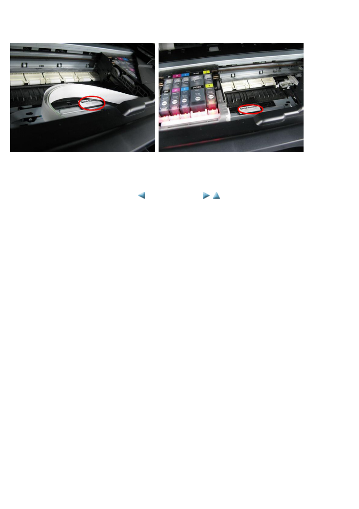
1-4. Serial Number Location
4 / 44
On the spur holder (visible when the scanning unit (cover) is opened)
When the machine power is OFF. When the machine power is ON.
<1. MAINTENANCE>
Page 7

MP620 / MP628 TABLE OF CONTENTS
5 / 44
2. LIST OF ERROR DISPLAY / INDICATION
Errors and warnings are displayed by the following ways:
1. Operator call errors are indicated by the Alarm LED lit in orange, and the error and its solution are displayed on the LCD in text
and by icon.
2. Messages during printing from a computer are displayed on the MP driver Status Monitor.
3. Error codes (the latest 10 error codes at the maximum) are printed in the "operator call/service call error record" area in EEPROM
information print
Buttons valid when an operator call error occurs:
1. ON button: To turn the machine off and on again.
2. OK button: To clear and recover from an error. In some operator call errors, the error will automatically be cleared when the cause
of the error is eliminated, and pressing the OK button may not be necessary.
3. Stop button: To cancel the job at error occurrence, and to clear the error.
2-1. Operator Call Errors (by Alarm LED Lit in Orange)
Error
No paper in the rear
tray.
No paper in the cassette. [1003] --- Cassette.
Paper jam. [1300] --- The paper is jammed. Clear the
Paper jam in the rear
guide.
Ink may have run out. [1600] U041 The following ink may have run out.
Ink tank not installed. [1660] U043 The following ink tank cannot be
Print head not installed,
or not properly
installed.
Error
codeU No.
[1000] --- Rear tray.
[1303] ---
[1401] U051 Print head is not installed. Install the
Message on the LCD Solution
There is no paper. Load paper and
press [OK].
There is no paper. Load paper and
press [OK].
paper and press [OK].
Replacing the ink tank is
recommended.
recognized.
(Applicable ink tank icon)
print head.
Confirm that the rear tray is selected as the paper
source. Set the paper in the rear tray, and press the
OK button.
Confirm that the cassette is selected as the paper
source. Set the paper in the cassette, and press the
OK button.
Note: Only plain paper can feed from the cassette.
Remove the jammed paper, and press the OK
button.
Replace the applicable ink tank, or press the OK
button to clear the error without ink tank
replacement. When the error is cleared by pressing
the OK button, ink may run out during printing.
Install the applicable ink tank(s) properly, and
confirm that the LED's of all the ink tanks light red.
Install the print head properly.
Faulty print head ID. U052 The type of print head is incorrect.
Print head temperature
sensor error.
Faulty EEPROM data of
the print head.
Multiple ink tanks of the
same color installed.
Ink tank in a wrong
position.
Warning: The ink
absorber becomes
almost full.
[1403]
[1405]
[1681] U071 More than one ink tank of the
[1680] U072 Some ink tanks are not installed in
[1700,
1701]
Install the correct print head.
following color is installed.
place.
--- Contact the support center or service
center for ink absorber replacement.
Press [OK] to continue printing.
Re-set the print head. If the error is not cleared, the
print head may be defective. Replace the print head.
Replace the wrong ink tank(s) with the correct one
(s).
Install the ink tank(s) in the correct position.
Replace the ink absorber, and reset its counter. [See
3-3. Adjustment / Settings, (6) Service mode.]
Pressing the OK button will exit the error, and
enable printing without replacing the ink absorber.
Page 8

However, when the ink absorber becomes full, no
6 / 44
further printing can be performed unless the
applicable ink absorber is replaced.
The connected digital
camera or digital video
camera does not support
Camera Direct Printing.
The remaining ink
amount unknown (raw
ink present).
Ink tank not recognized. [1684] U140 The following ink tank cannot be
Ink tank not recognized. [1410
[2001] --- The device may be incompatible.
Remove the device and check the
manual supplied with the connected
device.
[1683] U130 (Applicable ink tank icon)
The remaining level of the following
ink cannot be correctly detected.
Replace the ink tank.
recognized.
(Applicable ink tank icon)
U150 The following ink tank cannot be
to
1419]
recognized.
(Applicable ink tank icon)
Remove the cable between the camera and the
machine.
An ink tank which has once been empty is installed.
Replace the applicable ink tank with a new one.
Printing with a once-empty ink tank can damage the
machine.
To continue printing without replacing the ink tank
(s), press the Stop button for 5 sec. or longer to
disable the function to detect the remaining ink
amount. After the operation, it is recorded in the
machine EEPROM that the function to detect the
remaining ink amount was disabled.
A non-supported ink tank (an ink tank that is sold in
a different region from where the machine was
purchased) is installed (the ink tank LED is turned
off). Install the supported ink tanks.
A hardware error occurred in an ink tank (the ink
tank LED is turned off). Replace the ink tank(s).
No ink (no raw ink). [1688] U163 Printer detected ink out condition of
the following ink. Replace the ink
tank.
(Applicable ink tank icon)
Non-supported hub [2002] --- An unsupported USB hub is
connected. Remove the hub.
Time-out for the scanner
device
[2700] --- Timeout error has occurred. Press
[OK].
Replace the empty ink tank(s), and close the
scanning unit (cover).
Printing with an empty ink tank can damage the
machine.
To continue printing without replacing the ink tank
(s), press the Stop button for 5 sec. or longer to
disable the function to detect the remaining ink
amount. After the operation, it is recorded in the
machine that the function to detect the remaining
ink amount was disabled.
Remove the applicable USB hub from the
PictBridge (USB) connector.
The buffer became full in the middle of scanning
operation, and 60 minutes have elapsed since then,
making re-scanning unstable. Press the OK button
to clear the error.
Page 9

2-2. Service Call Errors (by Cyclic Blinking of Alarm and Power LEDs)
7 / 44
Service call errors are indicated by the number of cycles the Alarm and Power LEDs blink, and the corresponding error code with the
message,
"Printer error has occurred. Turn off power then back on again. If problem persists, see the manual." is displayed on the LCD.
Cycles of
blinking of
Alarm and
Power LEDs
Error
Error
code
Conditions
(Check points and replacement items)
Solution
2 times Carriage error [5100] An error occurred in the carriage
encoder signal.
3 times Line feed error [6000] An error occurred in the LF encoder
signal.
(1) Smearing or scratches on the carriage slit
film;
clean the timing slit film.
(2) Foreign material or paper debris that
obstructs the carriage movement;
remove foreign material.
(3) Ink tank conditions;
re-set the ink tanks.
(4) Cable connection
(5) Part replacement:
- Timing slit disk film
- Carriage unit
- Logic board
- Carriage motor
(1) Smearing or scratches on the LF / EJ slit
film;
clean the LF / EJ slit film.
(2) Foreign material or paper debris in the LF
drive;
remove foreign material.
(3) Cable connection
(4) Part replacement:
- LF / EJ slit film
- LF / EJ timing sensor unit
- Paper feed roller unit
- Logic board
- Paper feed motor
4 times Purge cam sensor
error
5 times ASF (cam) sensor
error
6 times Internal temperature
error
7 times Ink absorber full [5B00,
[5C00] An error occurred in the purge unit. (1) Foreign material or paper debris around the
[5700] An error occurred in the ASF cam
[5400] The internal temperature is not
5B01]
sensor.
normal.
The ink absorber is supposed to be
full.
Message on the LCD:
Ink absorber full. Service
required.
Error codes:
purge drive system unit;
remove foreign material.
(2) Cable connection
(3) Part replacement:
- Purge drive system unit
- Logic board
(1) Cable connection
(2) Part replacement:
- ASF unit
- PE sensor board unit
- Logic board
(1) Cable connection
(2) Part replacement:
- Carriage unit
- Logic board
- Print head
(1) Ink absorber condition
(2) Part replacement:
- Ink absorber kit
(3) Ink absorber counter value in the EEPROM;
reset the ink absorber counter.
Page 10

5B00: Main ink absorber is full
8 / 44
(overseas).
5B01: Main ink absorber is full
(Japan).
8 times Print head
temperature rise
error
9 times EEPROM error [6800,
10 times VH monitor error [B200] The internal temperature exceeded
11 times Carriage lift
mechanism error
12 times APP position error [6A80] An error occurred in the APP motor. (1) Foreign material or paper debris around the
14 times APP sensor error [6A90] An error occurred during paper
[5200] The print head temperature
exceeded the specified value.
A problem occurred in reading from
6801]
[5110] The carriage did not move up or
or writing to the EEPROM.
the specified value.
down properly.
feeding or purging.
(1) Print head condition
(2) Cable connection
(3) Part replacement:
- Print head
- Logic board
(1) Part replacement:
- Logic board
(1) Part replacement:
- Print head and logic board (Replace
them at the same time.)
- Power supply unit
(1) Foreign material or paper debris that
obstructs the carriage movement;
remove foreign material.
(2) Part replacement:
- Switch system unit
- Carriage unit
purge drive system unit;
remove foreign material.
(2) Foreign material or paper debris around the
ASF unit;
remove foreign material.
(3) Cable connection
(4) Part replacement:
- Purge drive system unit
- Logic board
Paper feed cam
sensor error
15 times USB Host VBUS
overcurrent
16 times Pump roller sensor
error
19 times Ink tank position
sensor error
[6B10] An error occurred in the paper feed
cam sensor during paper feeding
from the cassette, or the paper
absorbing a large amount of ink
jammed in the PF rear guide.
[9000] The USB Host VBUS is overloaded. (1) Part replacement:
[5C20] The pump roller position cannot be
detected.
[6502] None of the ink tank position is
detected.
(1) Jammed paper in the PF rear guide (when a
large amount of ink was absorbed in the
paper);
remove the jammed paper and foreign
material.
(2) Foreign material or paper debris in the
cassette or in the PF rear guide;
remove foreign material.
(3) Part replacement:
- PF pick-up unit
- Logic board
- Logic board
(1) Cable connection
(2) Part replacement:
- Purge drive system unit
(1) Ink tank position;
confirm the ink tank position.
(2) Re-set or replacement of ink tanks
(3) Cable connection
(4) Part replacement:
- Spur unit
- Logic board
20 times Other errors [6500] An unidentified error or a network
error occurred.
21 times Drive switch error [C000] Drive was not switched properly. (1) Foreign material or paper debris in the drive
(1) Part replacement:
- Logic board
- WLAN board
Page 11
switch area;
9 / 44
remove foreign material.
(2) Part replacement:
- Purge drive system unit
- ASF unit
22 times Scanner error [5011] An error occurred in the scanner. (1) Document pressure sheet conditions
(2) Cable connection
(3) Part replacement:
- Document pressure sheet (sponge
sheet)
- Scanner unit
- Logic board
Flatbed motor error [5012] An error occurred in the scanner
23 times Valve cam sensor
error
Before replacement of the logic board ass'y, check the ink absorber counter value (by service test print or EEPROM
information print). If the counter value is 7% or more, also replace the ink absorber kit when replacing the logic
board ass'y. If the counter value is less than 7%, register the current ink absorber counter value to the replaced new
logic board.
[See 3-3. Adjustment / Settings, (6) Service mode, for details.]
2-3. Other Error Messages
Message on the LCD Cause Solution
The selected paper cannot be fed from
cassette. Change the paper source and
press [OK].
flatbed motor.
[6C10] The valve cam sensor was faulty at
power-on or when purging was
attempted.
The paper type being used is not supported
for paper feeding from the cassette.
(1) Cable connection
(2) Part replacement:
- Scanner unit
(1) Foreign material or paper debris around the
purge drive system unit;
remove foreign material.
(2) Cable connection
(3) Part replacement:
- Purge drive system unit
- Logic board
Change the paper source to the rear tray.
Cannot apply the following setting(s).
Change the setting(s).
Device memory is full. Cannot
continue process. Reduce the number
of documents (photos, etc.) to scan or
copy.
Press [Color]. The Black button was pressed, but it is
Press [Black]. The Color button was pressed, but it is
There are no photos in memory card. Supported image files are not in the memory
The value exceeds the number of
copies you can print.
Settings made conflict each other. (e.g.
Selecting borderless printing on plain paper)
The memory is not sufficient to do the print
job in copying.
invalid.
invalid.
card.
During selecting images or specifying the
number of copies, the total print quantity
Change the settings so that they will not
conflict each other.
Reduce the amount of data to be printed, or
print from a computer.
A temporary error. Press the Color button to
continue the operation.
A temporary error. Press the Black button to
continue the operation.
A temporary error.
- Confirm that supported image files are in
the memory card.
- Images with double-byte characters used in
the file name (or folder name) may not be
recognized. Change the file (or folder)
name so that it contains only single-byte
alphanumeric characters.
- If images are edited on the computer, print
them from the computer.
A temporary error. The last operation before
the error is cancelled, and the total print
Page 12
exceeds the prescribed value of 999. quantity returns to the value before the error.
10 / 44
Memory card is not set. Insert the card
after checking the direction.
DPOF information is not saved. DPOF print was selected in the menu, but no
The number of copies to print is not
set. Input the number of copies using
[+]/[-].
This layout is available only for A4 or
8.5"x11" (215x279).
Cannot specify "stickers" and "halfside layout" together. Check markings
on handwriting sheet.
Change the setting after removing the
card.
The card is currently writable from PC.
Set to [Not writable from PC].
The memory card is not inserted in the slot
properly.
DPOF files are contained in the memory
card.
Printing was attempted with the print quantity
left "0" (zero).
In Layout print, "Mixed 1, 2, or 3" which is
available only with A4 or Letter size paper is
selected, but the paper size is not set to A4 or
Letter.
The selected layout on the handwriting sheet
is not supported for Stickers.
With a memory card inserted in the slot,
change of the Read/Write attribute was
attempted.
With the memory card set to "Writable from
PC," Card Direct printing operation was
attempted from the menu.
Set a memory card properly.
A temporary error. The LCD automatically
returns to the display before the error
occurrence.
A temporary error. Specify the print quantity.
A temporary error. The LCD automatically
returns to the display before the error
occurrence.
A temporary error. Press the OK button to
clear the error. The LCD returns to the
display before the error occurrence.
A temporary error. Remove the memory card,
then change the Read/Write attribute.
A temporary error. Remove the memory card,
change the memory card setting to Read-only,
then perform Card Direct printing.
The paper size is not correct. Check
the page size you have set.
Failed to scan Photo Index Sheet.
Check orientation and position, and
make sure platen and sheet are clean.
<See manual>
Failed to scan handwriting sheet.
Check orientation and position, and
make sure platen and sheet are clean.
Failed to scan Photo Index Sheet.
Check for missed and improper
markings.
Failed to scan handwriting sheet.
Check for missed and improper
markings.
Failed to scan. Either document cannot
be scanned or is not placed on the
platen glass.
Cover is open. Close cover. The cover was opened during printing. Close the cover. The LCD returns to the
Non-supported size of paper for Camera
Direct printing via PictBridge connection is
selected.
The machine failed in scanning the Photo
Index Sheet.
The machine failed in scanning the
handwritten Photo Index Sheet.
The machine scanned the Photo Index Sheet,
but markings in the sheet were incorrect.
The machine scanned the handwritten Photo
Index Sheet, but markings in the sheet were
incorrect.
The machine failed in scanning the document
for Fit-to-page copy.
Cancel printing on the digital camera.
Confirm the paper size, and print again.
Press the OK button to clear the error.
Confirm the following, then try again:
- Fill in all the circles on the Photo Index
Sheet.
- Place the sheet in the correct orientation and
position.
Press the OK button to clear the error.
Confirm the following, then try again:
- Fill in all the circles on the Photo Index
Sheet properly.
- Place the sheet in the correct orientation and
position.
Press the OK button to clear the error. Correct
the settings, then try the operation again.
display before the error occurrence.
Scanner is not operating correctly. The CIS cannot detect the home position, or
the scanner unit warming-up is not performed
properly at power-on.
Press the OK button to clear the error, and
turn the machine off and on again. If the error
still occurs, repair servicing is required.
Page 13
2-4. Warnings
11 / 44
Warning Message on the LCD Solution
Low ink "!" is indicated for an applicable ink tank icon in the
Status Monitor.
Since the ink will be used up soon, prepare for a new
ink tank.
Print head temperature
rise
Protection of excess rise
of the print head
temperature
Restrictions on paper The current paper cannot be set. Change the size and
USB cable not connected Set the PC to start scan. Connect the USB cable, then turn on the computer.
Cancellation of image
select information
If the print head temperature does not fall, the print
head error will occur.
If the print head temperature does not fall, the print
head error will occur.
type.
Reset the selected photo information?
Yes No
Do you want to clear the image scanned from the
photo?
Yes No
Do you want to clear the scanned image and rescan?
Yes No
When the print head temperature falls, the error is
automatically cleared. If the print head error is
indicated, repair servicing is required.
If the print head temperature exceeds the specified
limit, an intermission is inserted during printing.
Re-select the supported paper type and size.
- Select
=> The image selection is cancelled, and the
- Select No, and press the OK button.
=> The LCD returns to the display immediately
, and press the OK button.
Yes
LCD returns to the display before the
message was displayed.
before the message was displayed.
2-5. Troubleshooting by Symptom
Symptom Solution
Faulty operation The power does not turn on.
The power turns off immediately after
power-on.
(1) Confirm connection of the power supply unit:
- Harness and connector conditions
(2) Replace the following item(s):
- Logic board
- Power supply unit
- Panel board
A strange noise occurs. (1) Examine and remove any foreign material or paper debris.
(2) Replace the following item(s):
- The part generating the strange noise
- Logic board
The LCD does not display properly.
A portion of the LCD is not displayed.
The display flickers.
Paper feed problems (multi-feeding,
skewed feeding, no feeding).
(1) Confirm cable connection (LCD FCC and panel harness):
- Harness and connector conditions
- No cable breakage, etc.
(2) Replace the following item(s):
- LCD FFC
- LCD viewer unit
- Panel board
- Logic board
(1) Examine and remove any foreign material or paper debris.
(2) Confirm the PF rear cover and the cassette conditions.
(3) Confirm cable connection.
(4) Replace the following item(s):
- ASF unit (for paper feeding error from the rear
tray)
- PF pick-up unit (for paper feeding error from the
cassette)
- PE sensor board
- Pressure roller unit
- Cassette unit
Faulty scanning (no scanning, strange
noise).
(1) Confirm cable connection (scanner motor cable and CIS
FFC).:
- Harness and connector conditions
- No cable breakage, etc.
Page 14

(2) Replace the following item(s):
12 / 44
- Scanner unit
- Logic board
Unsatisfactory print quality No printing, or no color ejected.
Faint printing, or white lines on
printouts.
Uneven printing.
Improper color hue.
Paper gets smeared. (1) Clean the inside of the machine.
The back side of paper gets smeared. (1) Clean the inside of the machine.
Graphic or text is enlarged on printouts
in the carriage movement direction.
(1) Confirm the ink tank conditions:
- Confirmation of the air-through of an ink tank
(proper removal of the orange tape)
- Re-setting of an ink tank
(2) Remove foreign material from the purge unit caps, if any.
(3) Perform cleaning or deep cleaning of the print head.
(4) Perform print head alignment.
(5) Replace the following item(s):
*1
- Print head
- Logic board
- Purge drive system unit
(2) Perform bottom plate cleaning.
(3) Perform paper feed roller cleaning.
(2) Perform bottom plate cleaning.
(3) Examine the platen ink absorber.
(4) Examine the paper eject roller.
(5) Replace the following item(s):
- The part in the paper path causing the smearing
(1) Confirm that the carriage slit film is free from smearing or
scratches:
- Cleaning of the timing slit film.
(2) Replace the following item(s):
- Timing slit film
- Carriage unit
- Logic board
- Scanner unit (for copying)
, and ink tanks
Graphic or text is enlarged on printouts
in the paper feed direction.
Faulty scanning
Network connection problem No printing. (1) Examine if printing is performed properly via USB
No scanning. (1) Replace the following item(s):
Streaks or smears on the scanned image. (1) Clean the platen glass and the document pressure sheet.
(1) Confirm that the LF / EJ slit film is free from smearing or
scratches:
- Cleaning of the LF / EJ slit film.
(2) Replace the following item(s):
- LF / EJ slit film
- LF / EJ timing sensor unit
- Platen unit
- Logic board
- Scanner unit (for copying)
- Scanner unit
- Logic board
(2) Confirm the position of the document pressure sheet.
(3) Replace the following item(s):
- Scanner unit
- Document pressure sheet
- Logic board
connection.
(2) Confirm the network settings.
(3) Replace the following item(s):
- Logic board (for wired / wireless LAN)
- WLAN board (for wireless LAN)
*1: Replace the print head only after the print head deep cleaning is performed 2 times, and when the problem persists.
<2. LIST OF ERROR DISPLAY / INDICATION>
Page 15

MP620 / MP628 TABLE OF CONTENTS
13 / 44
3. REPAIR
3-1. Notes on Service Part Replacement (and Disassembling / Reassembling)
Service part
Logic board ass'y - Before removal of the logic board
Absorber kit
Notes on replacement
ass'y, remove the power cord,
and allow for approx. 1 minute
(for discharge of capacitor's
accumulated charges), to prevent
damages to the logic board ass'y.
- Before replacement, check the
ink absorber counter value (by
service test print or EEPROM
information print).
*1
Adjustment / settings Operation check
After replacement:
1. Initialize the EEPROM.
2. Set the ink absorber counter
value.
3. Set the destination in the
EEPROM.
4. Check the ink system function.
5. Perform LF / Eject correction.
6. Perform button and LCD test.
Perform 1 to 6 in the service
mode.
[See 3-3. Adjustment /
Settings, (6) Service mode, for
details.]
7. Perform print head alignment
and LCD language setting in
the user mode.
8. Reset the LAN settings in the
user mode.
After replacement:
1. Reset the ink absorber counter.
[See 3-3. Adjustment /
Settings, (6) Service mode, for
details.]
- EEPROM information print
- Service test print
- Printing via USB connection
- Copying
- Direct printing from a digital
camera (PictBridge)
- Ink absorber counter value
print (After the ink absorber
counter is reset, the counter
value is printed
automatically.)
Carriage unit
Switch system unit - The red screws securing the paper
feed motor are allowed to be
Paper feed motor
loosened only for paper feed
motor replacement. (DO NOT
loosen them in any other cases.)
At replacement:
1. Before removal of the carriage
rail, mark the carriage rail
position.
[See 3-2. Special Notes on
Repair Servicing, (7) Carriage
unit removal, for details.]
2. Apply grease to the sliding
portions of the carriage rail.
[See 3-3. Adjustment /
Settings, (3) Grease
application, for details.]
3. Check the ink system function.
[See 3-3. Adjustment /
Settings, (6) Service mode, for
details.]
4. Perform print head alignment in
the user mode.
At replacement:
1. Adjust the paper feed motor.
[See 3-3. Adjustment /
Settings, (1) Paper feed motor
adjustment, for details.]
- Service test print (Confirm ink
system function.)
- EEPROM information print
- Service test print
Platen unit
After replacement:
1. Perform LF / Eject correction in
the service mode.
[See 3-3. Adjustment /
Settings, (6) Service mode, for
details.]
- EEPROM information print
- Service test print
Page 16
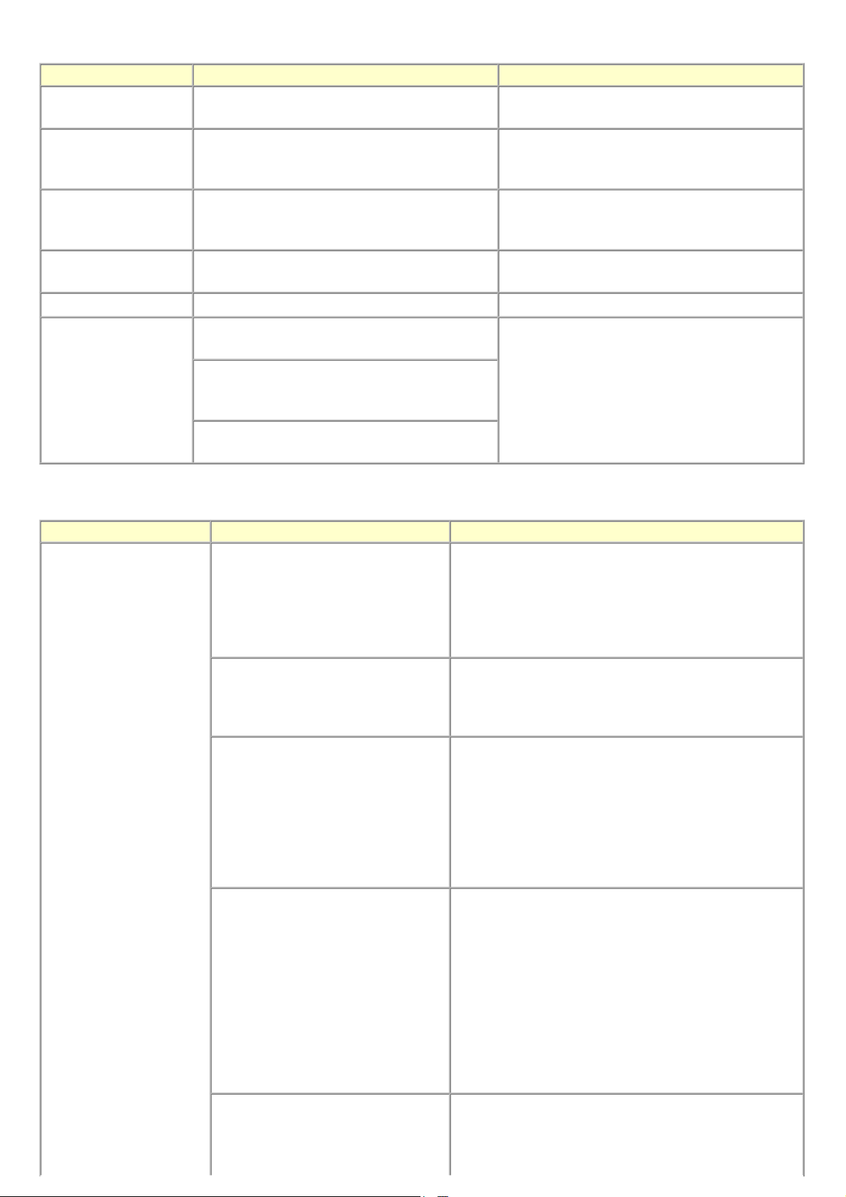
Spur unit - DO NOT contact the spur edges.
14 / 44
After replacement:
1. Check the ink system function.
2. Perform LF / Eject correction in
the service mode.
[See 3-3. Adjustment /
Settings, (6) Service mode, for
details.]
- EEPROM information print
- Service test print
Purge drive system unit
Carriage rail and main
chassis
Idler pulley parallel pin
Easy-Scroll Wheel base
APP code wheel gear shaft
Document pressure sheet
Document bottom cover
Scanner unit
Panel board ass'y - Be cautious not to scratch or
damage the LCD cable.
LCD viewer unit
After replacement:
1. Confirm the purging operation
and the machine operation.
[See 3-4. Verification After
Repair for details.]
At replacement:
1. Apply grease to the sliding
portions.
[See 3-3. Adjustment /
Settings, (3) Grease
application, for details.]
After replacement:
1. Confirm the document pressure
sheet position.
[See 3-3. Adjustment /
Settings, (2) Document
pressure sheet replacement, for
details.]
At replacement:
1. Perform button and LCD test.
[See 3-3. Adjustment /
Settings, (6) Service mode, for
details.]
- Service test print
- Service test print
- Service test print
- Service test print
Timing slit strip film - Upon contact with the film, wipe
the film with ethanol.
- Confirm no grease is on the film.
(Wipe off any grease thoroughly
Timing slit disk feed film
with ethanol.)
- Do not bend the film
Print head
Wireless LAN board ass'y
After replacement:
1. Perform print head alignment in
the user mode.
2. Perform LF / Eject correction in
the service mode.
[See 3-3. Adjustment /
Settings, (6) Service mode, for
details.]
After replacement:
1. Perform print head alignment in
the user mode.
After replacement:
1. Reset the LAN settings in the
user mode.
2. Print the EEPROM information
to confirm that the WL LAN
MAC address is properly
updated.
[See 3-3. Adjustment /
Settings, (6) Service mode, for
details.]
- EEPROM information print
- Service test print
- Service test print
- EEPROM information print
- Service test print
Page 17

*1: General notes:
15 / 44
- Make sure that the flexible cables and wires in the harness are in the proper position and connected correctly. See 3-2. Special
Notes on Repair Servicing or the Parts Catalog for details.
- Do not drop the ferrite core, which may cause damage.
- Protect electrical parts from damage due to static electricity.
- Before removing a unit, after removing the power cord, allow the machine to sit for approx. 1 minute (for capacitor discharging
to protect the logic board ass'y from damages).
- Do not touch the timing slit strip film and timing slit disk feed film. No grease or abrasion is allowed.
- Protect the units from soiled with ink.
- Protect the housing from scratches.
- Exercise caution with the screws, as follows:
i. The screws of the paper feed motor may be loosened only at replacement of the paper feed motor unit (DO NOT
loosen them in other cases).
ii. Before loosening the 3 screws that fix the carriage rail to the main chassis, mark the screw positions so that the
carriage rail will be re-attached to the main chassis in its original position.
<3-1. Notes on Service Part Replacement>
Page 18
MP620 / MP628 --- 3. REPAIR TABLE OF CONTENTS
16 / 44
3-2. Special Notes on Repair Servicing (Click on the image to enlarge it.)
Be sure to protect the machine from static electricity in repair servicing, especially for the LCD, operation panel board, scanner unit, logic
board, card board, IrDA board, PE sensor board, and WLAN board.
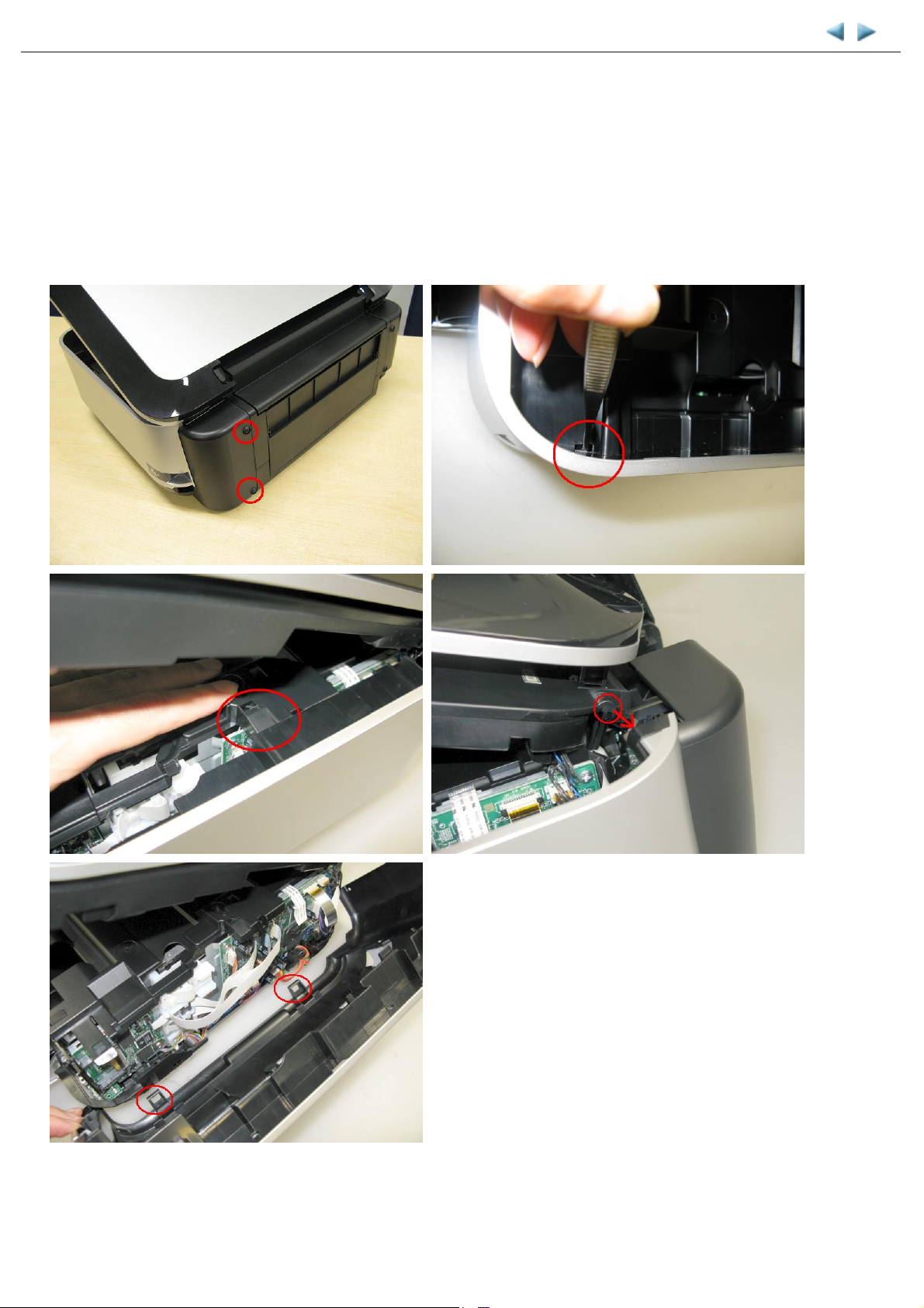
(1) External housing, scanner unit, and document cover removal
1) Remove the cassette.
2) Open the front door and scanner unit, then remove the side cover R (2 screws).
<The scanner unit hinges are fitted in the right and left side covers.>
Page 19
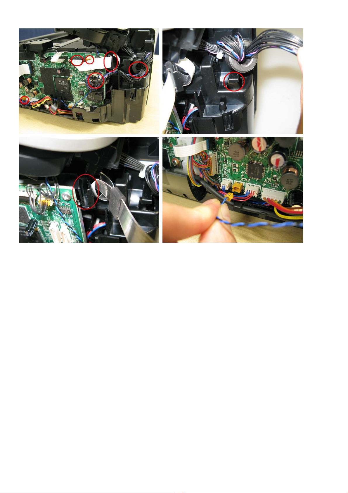
3) Remove the scanner cable, panel cable, FB encoder cable, and core.
17 / 44
<The core is fixed on the rib of the sub-case (back of the main case).>
Page 20
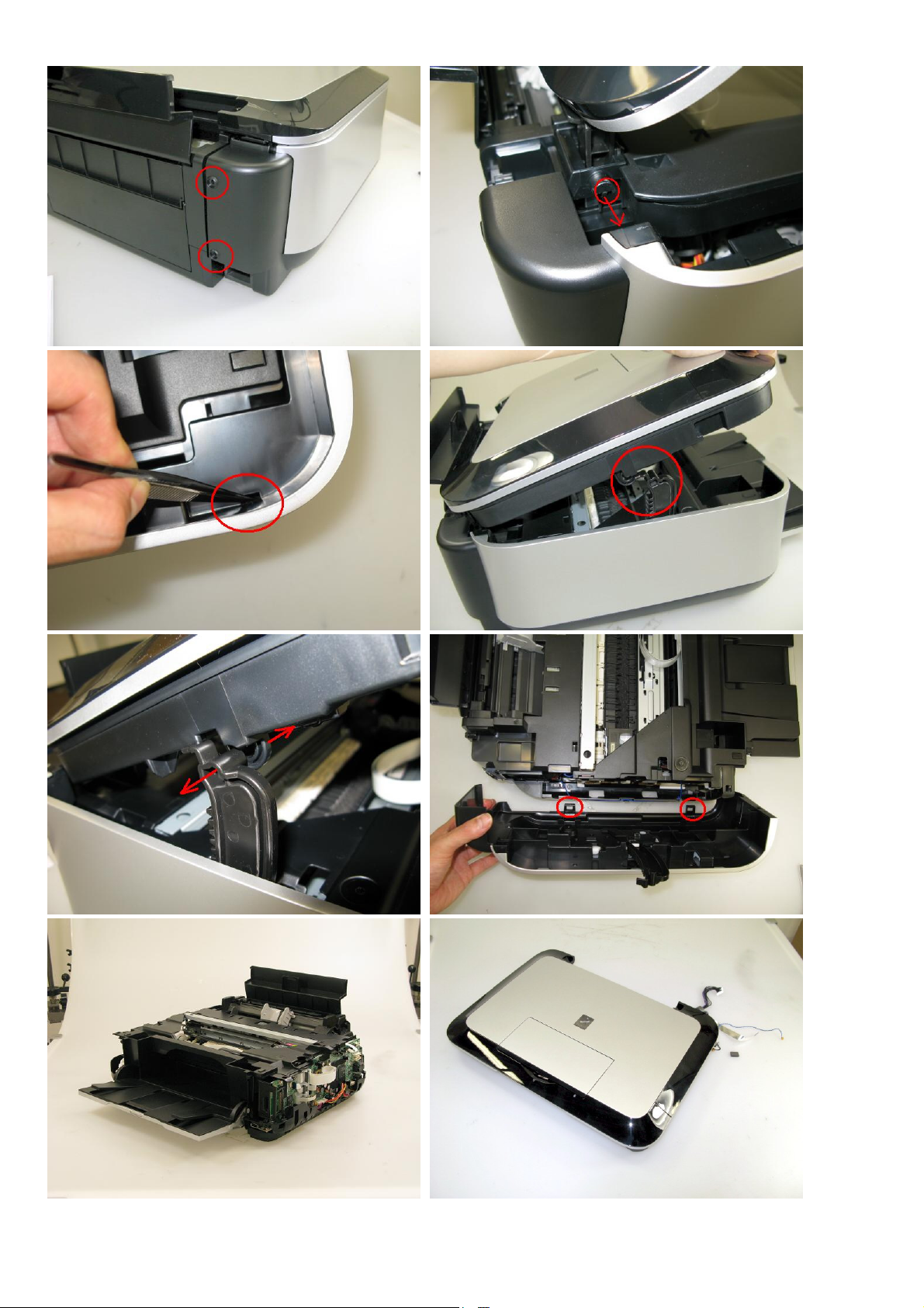
4) Remove the side cover L, scanner unit, then document pressure plate unit (2 screws).<While holding the scanner unit,
18 / 44
remove the side cover L, then disengage the scanner unit from the scanner support arm.>
Page 21
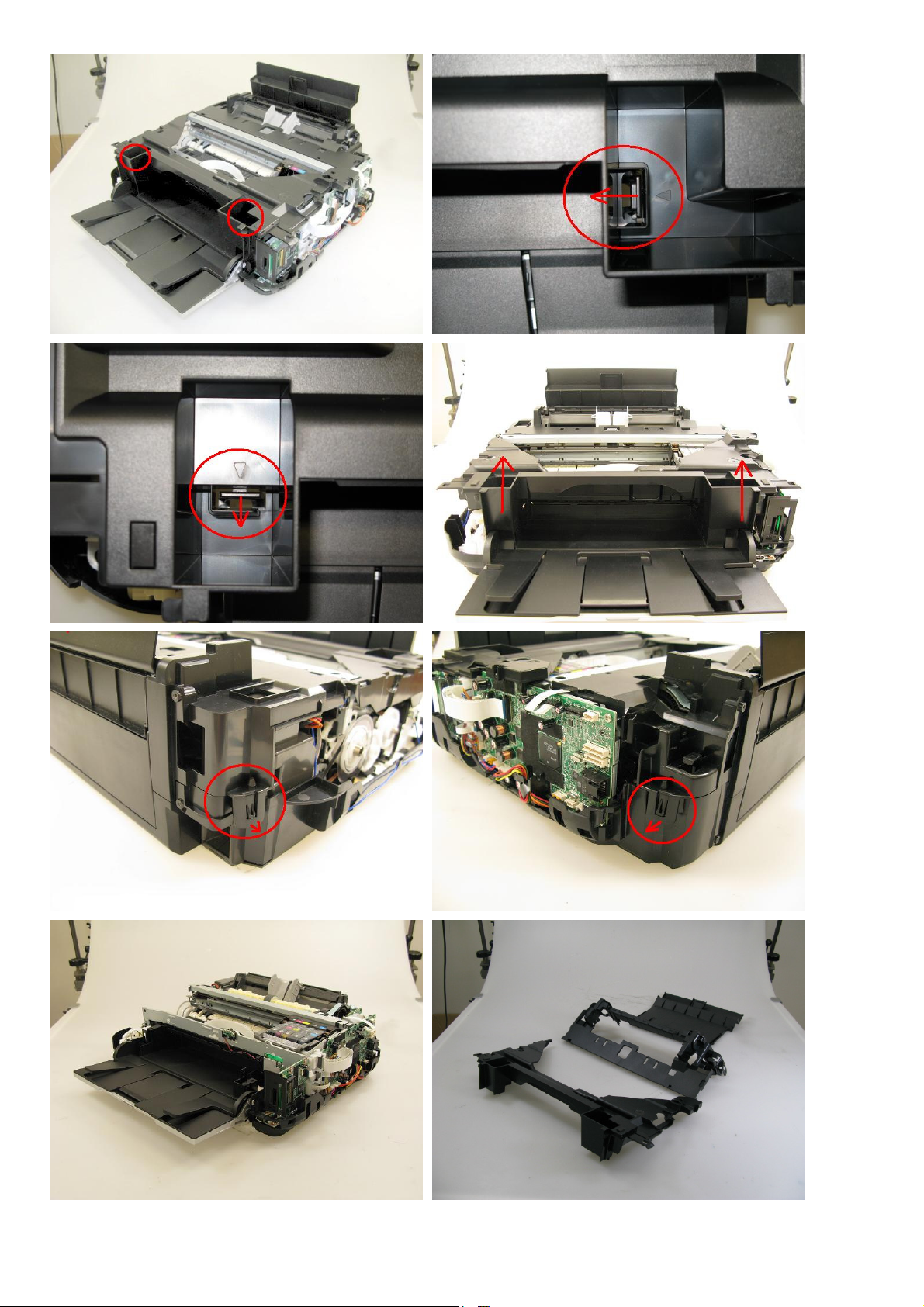
5) Remove the main case and sub-case.
19 / 44
Page 22
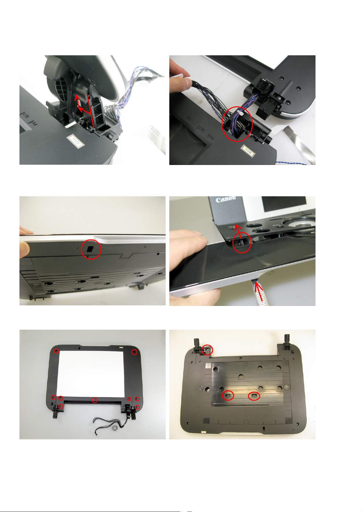
(2) Operation panel removal
20 / 44
1) Separate the document pressure plate from the scanner unit.
<While pushing the hinge edge inward, pull the plate upward to separate it from the scanner unit.>
<Remove the panel cable from the scanner unit. It will make it easier if the cable core is removed first.>
2) Remove the panel cover.
<Insert a pair of tweezers through into the hole in the bottom of the document pressure plate, and push the panel cover
to release it from the plate base.>
3) Remove the top cover from the base (9 screws).
<There are 2 claws at the center of the top cover where the document pressure sheet (sponge sheet) is attached..>
Page 23
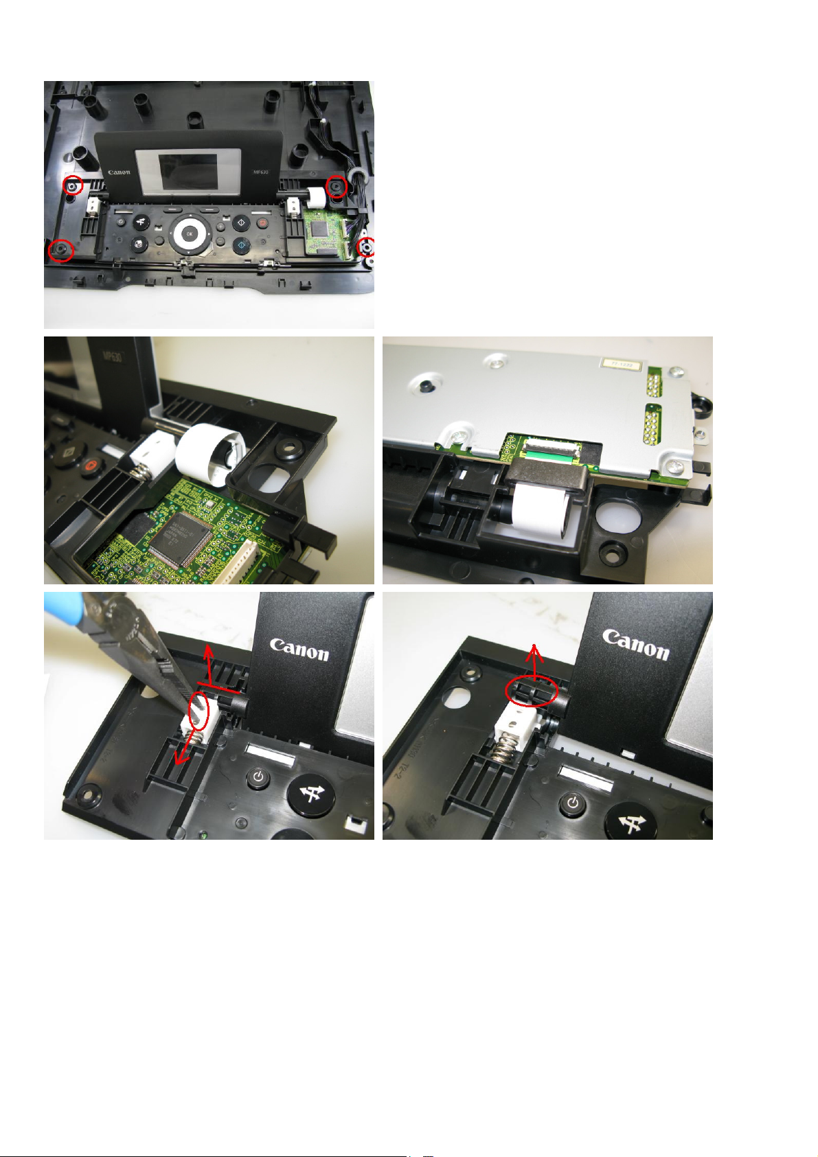
4) Remove the operation panel unit from the base (4 screws).
21 / 44
<For the hinge cable core position and cable layout, see the photos below. Use the longnose pliers in disengaging the
hinge and in releasing the spring.>
Page 24
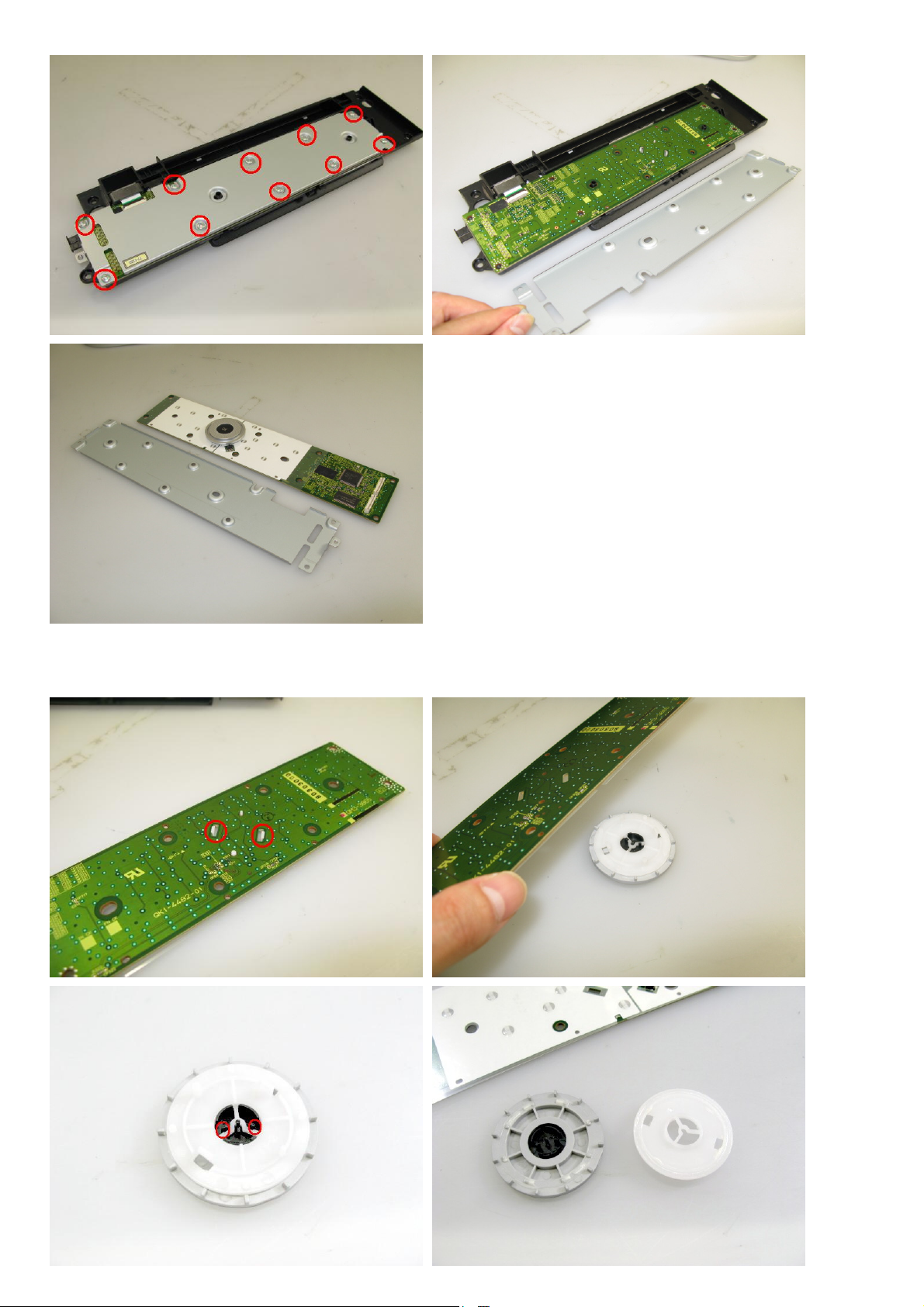
5) Remove the panel board (10 screws).
22 / 44
6) Remove the Easy-Scroll Wheel from the panel board.
<Be cautious not to touch the grease between the wheel base and the wheel.>
See 3-3. Adjustment / Settings, (3) Grease application.
Page 25
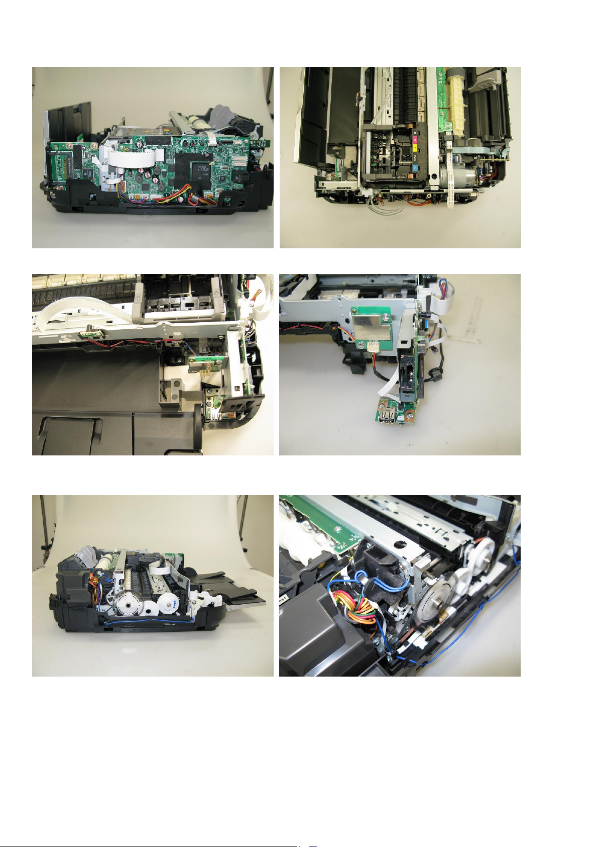
(3) Cable wiring and connection
23 / 44
1) Wiring on the right side
2) Wiring of the ink sensor cable and the WLAN harness
Bottom case and panel cover removed
3) Wiring on the left side. Hook the ground cable on the side of the bottom case.
Page 26
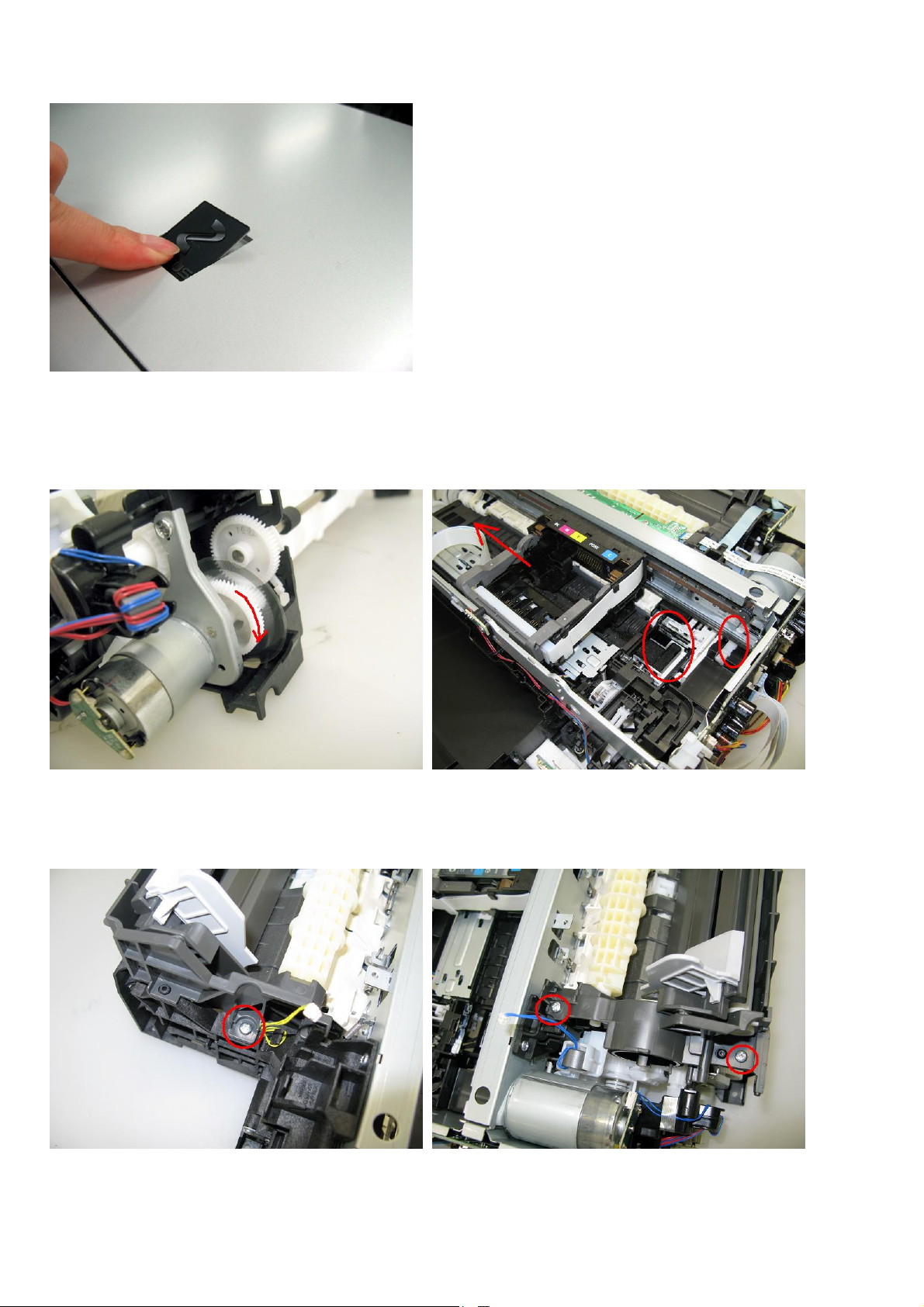
(4) Emblem removal
24 / 44
Push the emblem bottom to remove from the double-sided adhesive tape.
(5) Carriage unlocking
1) Rotate the drive unit gear toward the back of the machine to unlock the carriage.
Slide the carriage to the left (the opposite of the home position).
(6) ASF unit removal
1) Remove 1 screw from the left plate, and 2 screws from the right plate.
Page 27
25 / 44
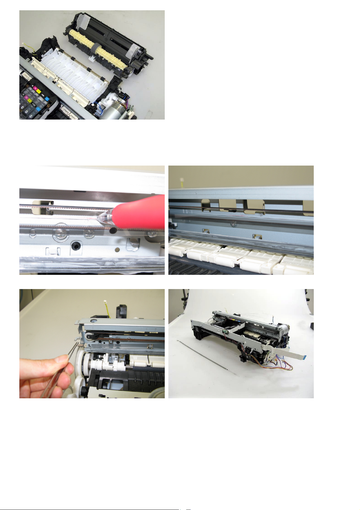
(7) Carriage unit removal
1) At first, on the main chassis, mark the positions of the screws that fix the carriage rail to the main chassis (3 points for
each screw: the left, right, and center).
2) Remove the timing slit film. Be cautious to keep the film free from any grease or scratches.
Page 28
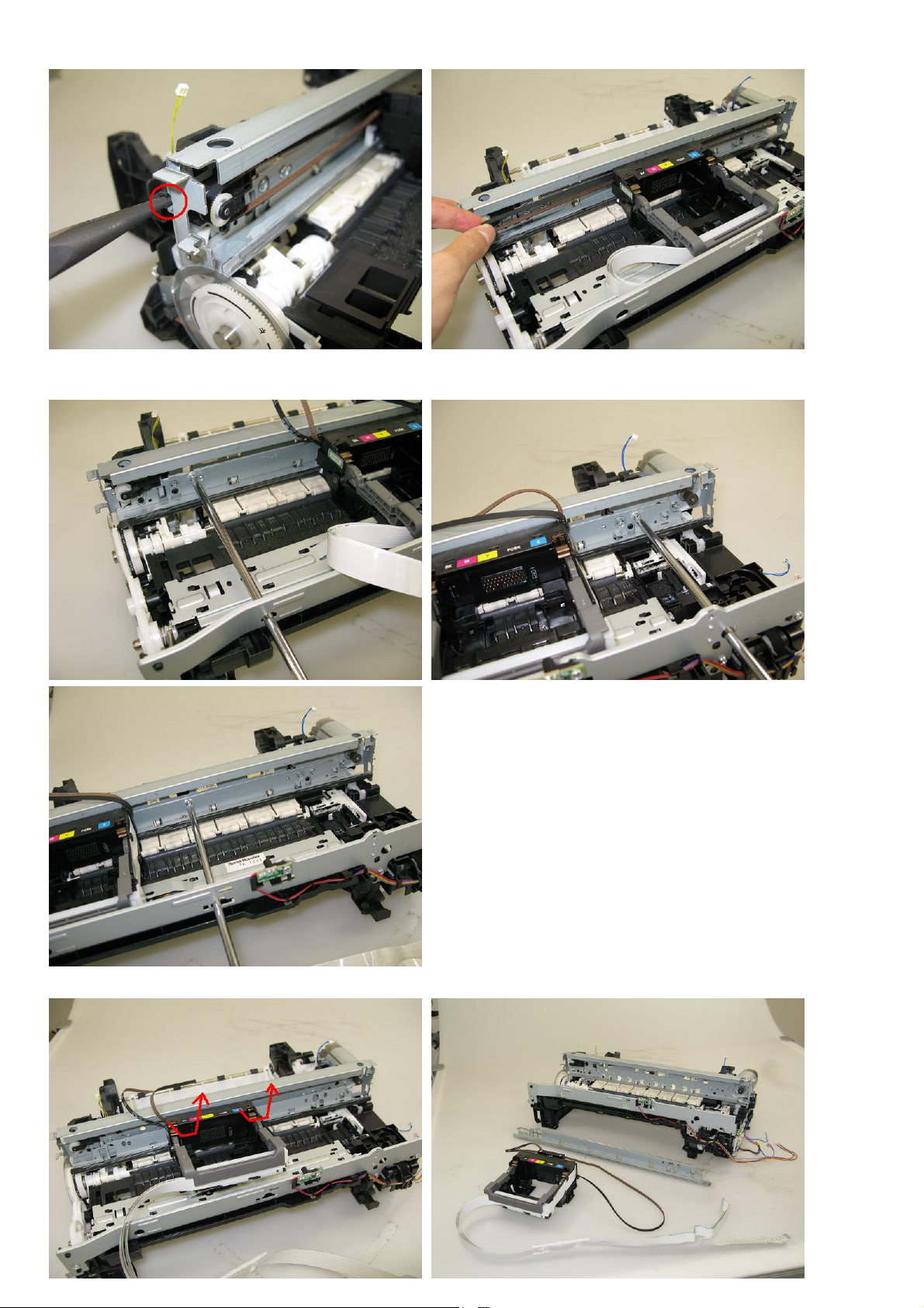
3) Using a longnose pliers, release the left end of the pulley holder spring, and remove the carriage belt.
26 / 44
Be cautious to keep the belt free from any grease.
4) Remove 3 screws that fix the carriage rail to the main chassis. Before removing the center screw, remove the carriage
cable holder from the front chassis. After the 3 screws are removed, slowly put down the carriage rail.
5) Remove the carriage unit. Be cautious that the grease will not attach to any parts.
Page 29
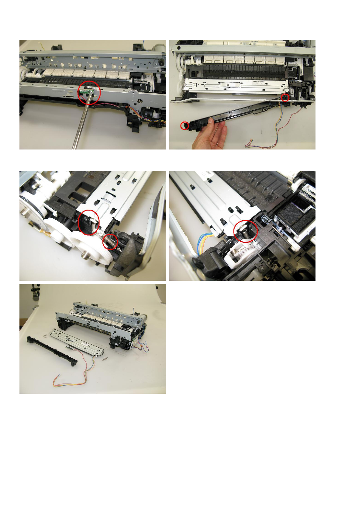
(8) Spur unit and platen unit removal
27 / 44
1) Remove the ink sensor and the middle front cover from the front chassis.
2) From the left and right sides of the spur unit, release the springs (2 on the left side, 1 on the right side). Then, slowly
pull the spur unit upward to remove it from the platen unit.
Page 30
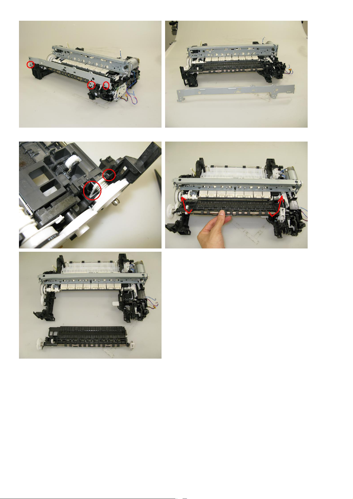
3) Remove the front chassis (3 screws).
28 / 44
4) Unlock the paper eject roller gear. While raising the front of the platen unit, remove the platen unit from the printer unit.
Page 31
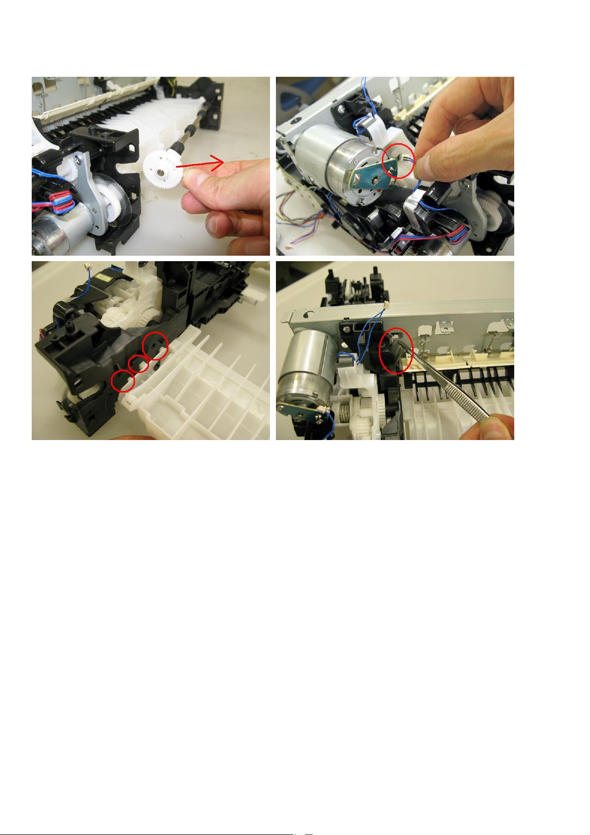
(9) Purge drive system unit (right plate) and switch system unit (left plate) removal
29 / 44
1) Release the springs of the carriage motor cable, duplex printing paper feed roller, cassette feed roller, cassette feed
guide, and paper guide unit (both sides). (See the Parts Catalog for details.)
2) Remove the pressure roller springs (both the left and the right ones).
Page 32
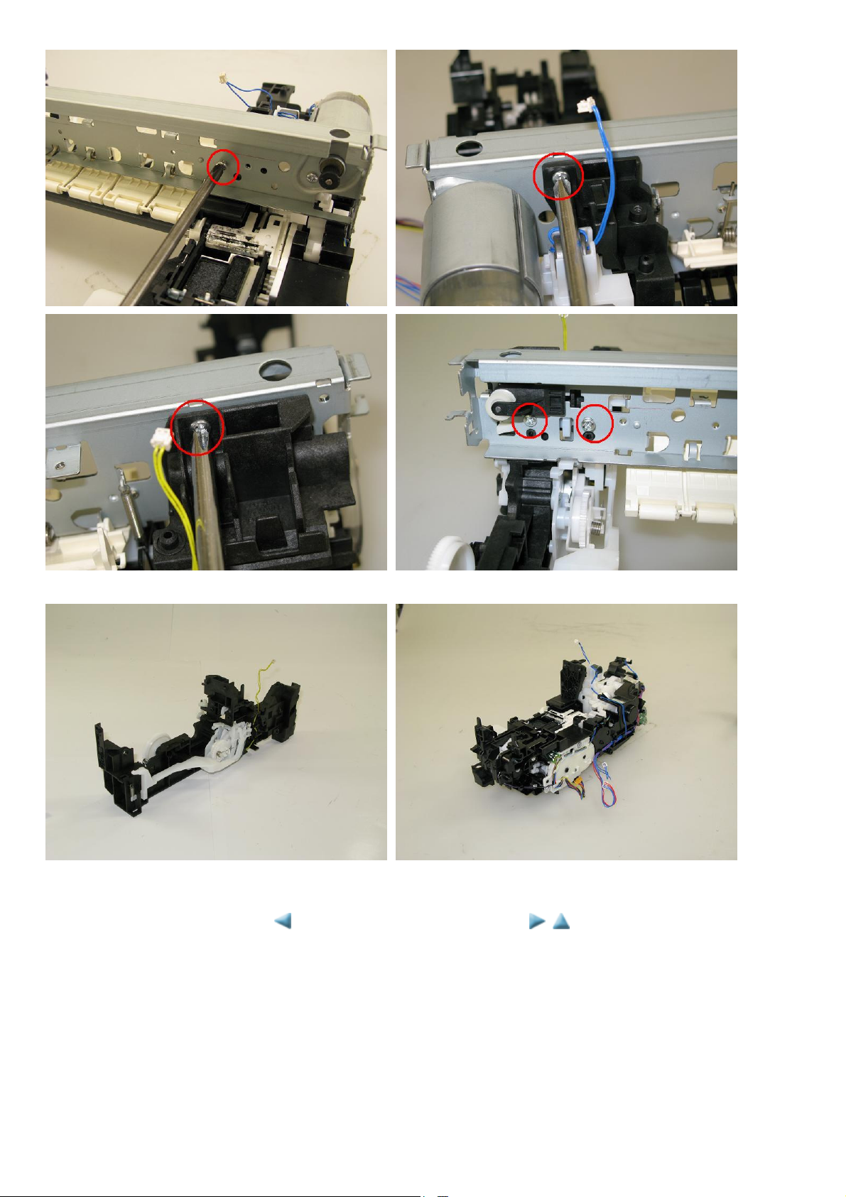
3) Remove the screws that fix the units to the main chassis (2 on the right, 3 on the left).
30 / 44
4) Separate the main chassis from the switch system unit and the purge drive system unit.
<3-2. Special Notes on Repair Servicing>
Page 33
MP620 / MP628 --- 3. REPAIR TABLE OF CONTENTS
31 / 44
3-3. Adjustment / Settings
(1) Paper feed motor adjustment
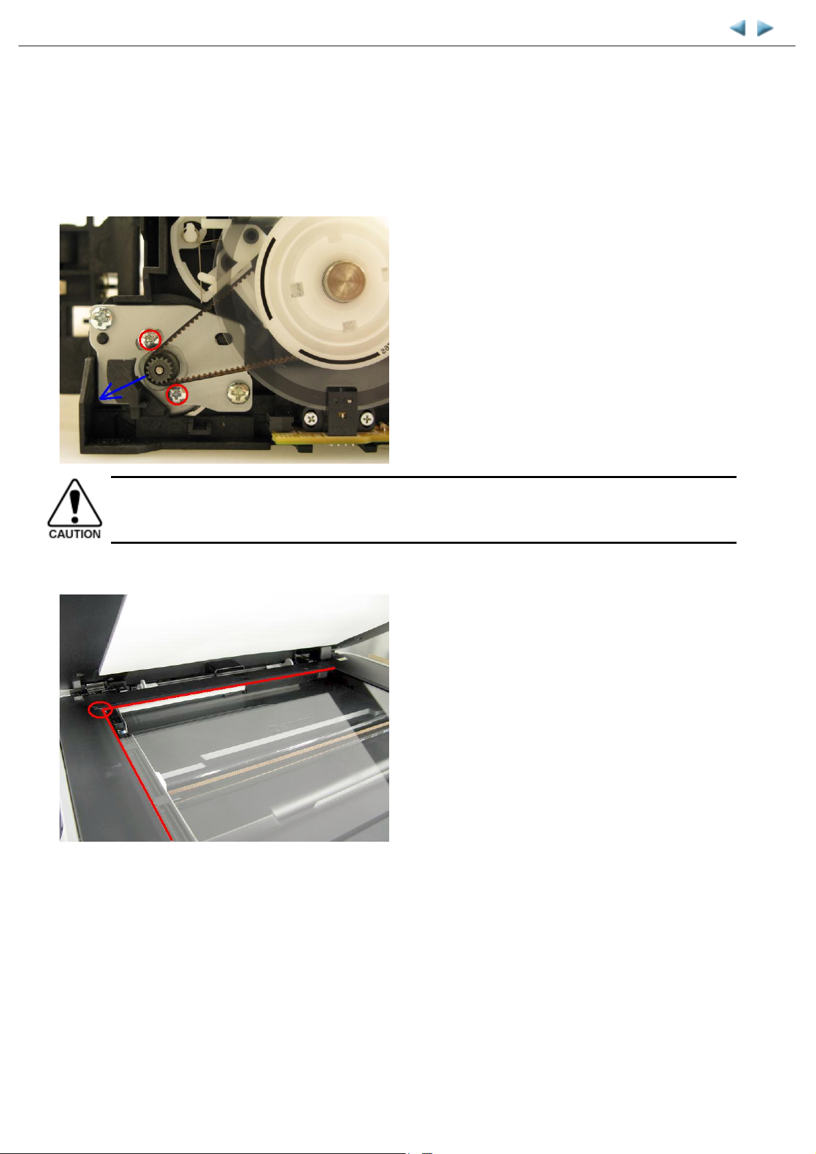
1) When attaching the motor, fasten the screws so that the belt is properly stretched (in the direction indicated by the blue arrow in the photo
below).
2) After replacement, be sure to perform the service test print, and confirm that no strange noise or faulty print operation (due to dislocation of
the belt or gear, or out-of-phase motor, etc.) occurs.
The screws securing the paper feed motor may be loosened only at replacement of the paper feed motor unit. DO
NOT loosen them in other cases.
(2) Document pressure sheet (sponge sheet) replacement
1) Peel off the cover sheet from the double-sided adhesive tape on the back of the document pressure sheet.
With the long-side down, position the upper-left corner of the document pressure sheet at the scanning reference point on the platen glass
(back left where the red lines cross in the photo above).
2) Slowly close the document pressure plate while maintaining the hinge position. The document pressure sheet will attach to the plate.
3) Open the plate to confirm the following:
- No extension of the sponge edges over the mold part of the upper scanner cover.
- No gap between the platen glass reference edges and the corresponding sponge edges.
- No shades or streaks in monochrome test printing without a document on the platen glass.
Page 34
(3) Grease application
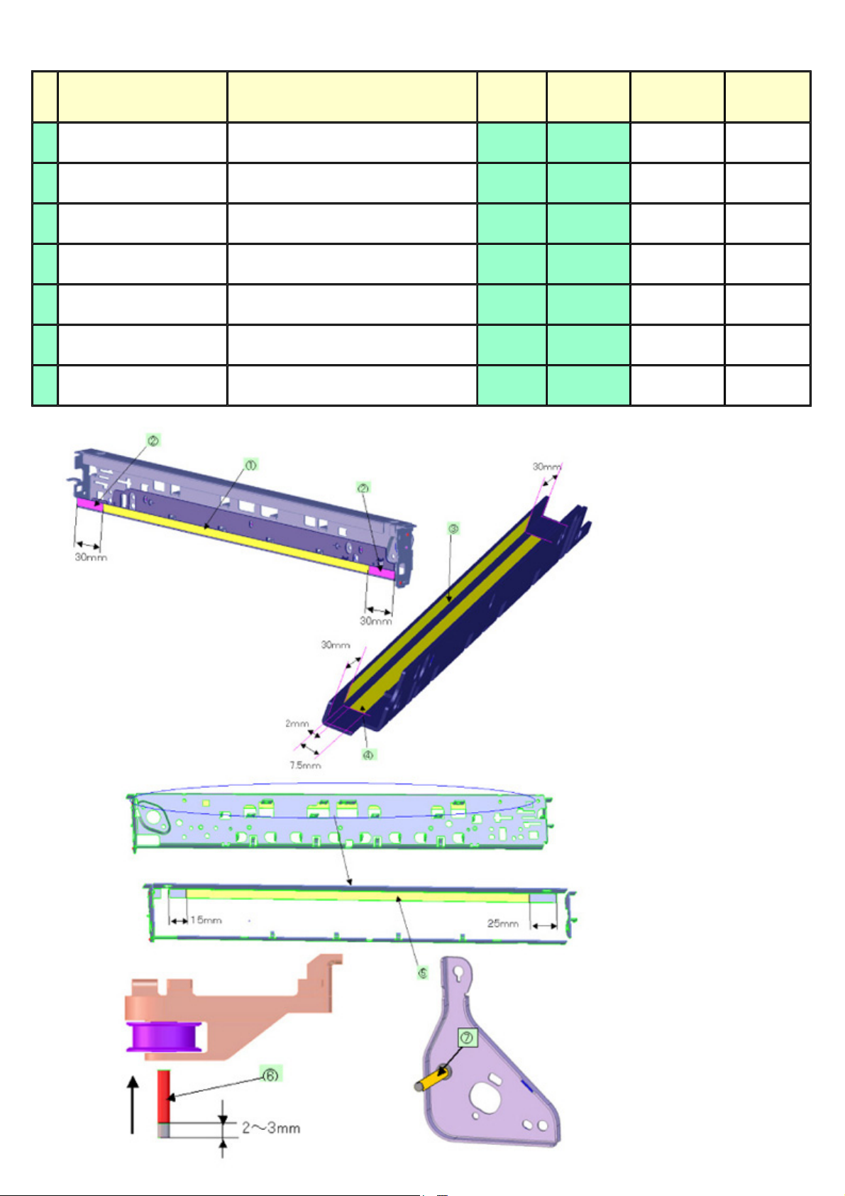
32 / 44
1) Printer unit
No Part name Where to apply grease / oil
1 Carriage rail The surface where the carriage unit slides (1)
2 Carriage rail The surface where the carriage unit slides (2)
3 Carriage rail The surface where the carriage unit slides (3)
4 Carriage rail The surface where the carriage unit slides (4)
5 Main chassis The surface where the carriage unit slides (5)
6 Parallel pin
7 APP code wheel gear shaft
1 drop = 9 to 18 mg
The pin surface which contacts the idler
pulley hole
APP code wheel gear sliding portion (the
entire surface)
Drawing
No.
(6)
(7)
Grease
Floil
KG107A
Floil
KG107A
Floil
KG107A
Floil
KG107A
Floil
KG107A
Floil
KG107A
Floil
KG107A
Grease
amount (mg)
270 to 330 ---
18 to 36 1 x 2
360 to 440 ---
360 to 440 ---
230 to 290 ---
9 to 18 1 x 1
9 to 18 1 x 1
Number of
locations
drops x
Page 35
2) Operation panel, Easy-Scroll Wheel
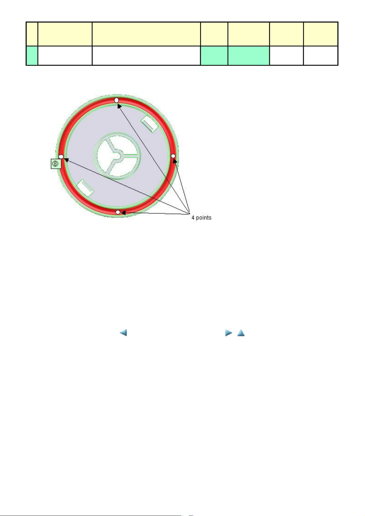
33 / 44
No Part name Where to apply grease / oil
Easy-Scroll Wheel
8
base
1 drop = 9 to 18 mg
Easy-Scroll Wheel sliding portions (8) Floil KG107A 9 to 18 ---
Drawing
No.
Grease
Grease
amount
(mg)
Number of
drops x
locations
(4) Ink absorber counter setting
Before replacement of the logic board, check the ink absorber counter value, and register it to the replaced new logic board. (The value can be
set in 10% increments.)
In addition, according to the ink absorber counter value, replace the ink absorber (ink absorber kit). When the ink absorber is replaced, reset the
applicable ink absorber counter (to 0%).
- How to check the ink absorber counter value and the way to set the ink absorber counter:
See 3-3. Adjustment / Settings, (6) Service mode, "Ink absorber counter setting."
<3-3. Adjustment / Settings, (1) to (4)>
Page 36

MP620 / MP628 --- 3. REPAIR TABLE OF CONTENTS
34 / 44
(5) User mode
Function Procedures Remarks
Nozzle check pattern printing Perform via the machine operation panel, or from the
MP driver Maintenance tab.
Print head manual cleaning - Cleaning both Black and Color:
Perform via the machine operation panel.
- Cleaning Black or Color separately, or both Black
and Color:
Perform from the MP driver Maintenance tab.
Print head deep cleaning Perform via the machine operation panel, or from the
MP driver Maintenance tab.
Manual print head alignment Perform via the machine operation panel, or from the
MP driver Maintenance tab.
Print head alignment value
printing
Paper feed roller cleaning Perform via the machine operation panel, or from the
Perform via the machine operation panel, or from the
MP driver Maintenance tab.
MP driver Maintenance tab.
Set a sheet of plain paper (A4 or Letter) in
the cassette, or the rear tray if selected.
Unclogging of the print head nozzles, and
maintenance to keep the print head
conditions good.
If there is a missing portion or white streaks
in the nozzle check pattern printout, perform
this cleaning.
If print head manual cleaning is not
effective, perform this cleaning. Since the
deep cleaning consumes more ink than
regular cleaning, it is recommended to
perform deep cleaning only when necessary.
Set 3 sheets of plain paper (A4 or Letter) in
the cassette, or the rear tray if selected.
Confirmation of the current print head
alignment values.
The paper feed rollers of the selected paper
source (the rear tray or the cassette) rotate
while being pushed to the paper lifting
plate. Since the rollers will wear out in this
cleaning, it is recommended that you
perform this only when necessary.
Bottom plate cleaning Perform via the machine operation panel, or from the
MP driver Maintenance tab.
LAN resetting Perform via the machine operation panel, or using IJ
Network Tool on the computer.
LAN setting information
display
Perform via the machine operation panel, or using IJ
Network Tool on the computer.
Cleaning of the platen ribs when the back
side of paper gets smeared.
Fold a sheet of plain paper (A4 or Letter) in
half crosswise, then unfold and set it in the
rear tray with the folded ridge facing down.
(No paper feeding from the cassette)
Reset the LAN settings to the ones when the
machine was purchased, via the machine
operation panel (by selecting
Device settings, LAN setting
LAN settings
the computer.
Confirm the wired or wireless LAN settings,
via the machine operation panel (by
selecting
setting
Wireless LAN setting list
Network Tool on the computer.
), or using IJ Network Tool on
Settings, Device settings, LAN
, then
Wired LAN setting list
Settings
, then
), or using IJ
,
Reset
or
Page 37
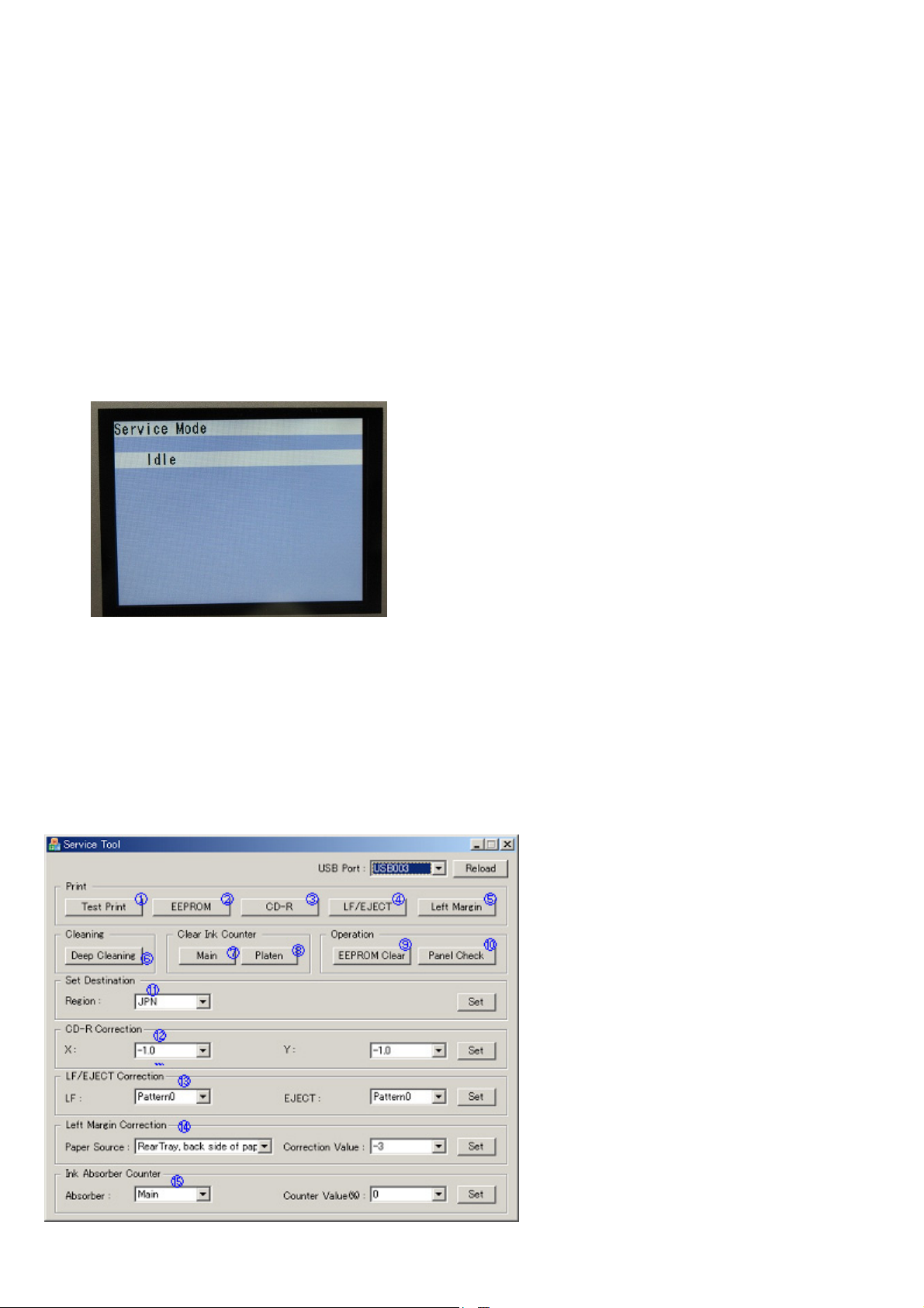
(6) Service mode
35 / 44
<Service mode operation procedures>
Use the Service Tool on the connected computer.
1) Start the machine in the service mode.
i. With the machine power turned off, while pressing the Stop button, press and hold the ON button. (DO NOT release the buttons.)
ii. When the Power LED lights in green, while holding the ON button, release the Stop button. (DO NOT release the ON button.)
iii. While holding the ON button, press the Stop button 2 times, and then release both the ON and Stop buttons. (Each time the Stop
button is pressed, the Alarm and Power LEDs light alternately, Alarm in orange and Power in green, starting with Alarm LED.)
iv. When the Power LED lights in green and the machine displays "Service Mode Idle," the machine is ready for the service mode
operation.
LCD ready for the service mode operation:
2) Start the Service Tool on the connected computer.
i. When a button is clicked in the Service Tool dialog box, that function is performed. During operation of the selected function, all the
Service Tool buttons are dimmed and inactive.
ii. When the operation is completed, "A function was finished." is displayed, and another function can be selected.
iii. If a non-supported function is selected, "Error!" is displayed. Click OK in the error message dialog box to exit the error.
<Service Tool functions>
Page 38
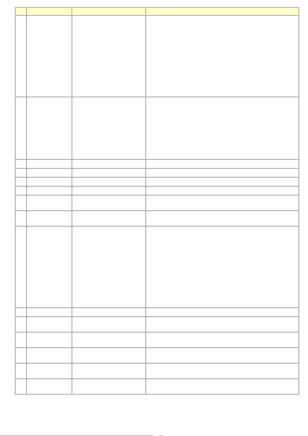
No. Name Function Remarks
36 / 44
(1) Test Print Service test print Paper will feed from the rear tray.
Service test print:
- Model name
- ROM version
- Ink absorber counter value (ink amount in the ink absorber)
- USB serial number
- Destination
- EEPROM information
- Process inspection information
- Barcode (model name + destination)
- Ink system function check result
(2) EEPROM EEPROM information print The dialog box opens to select the paper source. Select
Cassette
EEPROM information print:
- Model name
- ROM version
- Ink absorber counter value (ink amount in the ink absorber)
- Print information
- Error information, etc.
(3) CD-R CD-R check pattern print Not used.
(4) LF / Eject LF / Eject correction pattern print See "LF / Eject correction" below.
(5) Left Margin Left margin pattern print Not used.
(6) Deep Cleaning Print head deep cleaning Cleaning of both Black and Color at the same time
(7) Main Main ink absorber counter
resetting
(8) Platen Platen ink absorber counter
resetting
(9) EEPROM Clear EEPROM initialization The following items are NOT initialized, and the shipment arrival flag is
Set a sheet of A4 or Letter sized plain paper. After the ink absorber
counter is reset, the counter value is printed automatically.
Not used.
not on:
- USB serial number
- Destination settings
- Record of ink absorber counter resetting and setting
- Record of repair at the production site
- LF / Eject correction values
- Left margin correction value
- Production site E-MIP correction value and enabling of it
- Endurance correction value and enabling of it
- Record of disabling the function to detect the remaining ink amount
- Ink absorber counter value (ink amount in the ink absorber)
, and click OK.
Rear tray
or
(10) Panel Check Button and LCD test See "Button and LCD test" below.
(11) Set Destination Destination settings Select the destination, and click OK.
ASA, AUS, BRA, CHN, CND, EUR, JPN, KOR, LTN, TWN, USA
(12) CD-R Correction CD / DVD print position
correction (X and Y direction)
(13) LF / EJECT
Correction
(14) Left Margin
Correction
(15) Ink Absorber
Counter
LF / Eject correction value setting See "LF / Eject correction" below.
Left margin correction value
setting
Ink absorber counter setting See "Ink absorber counter setting" below.
Not used.
Not used.
Page 39
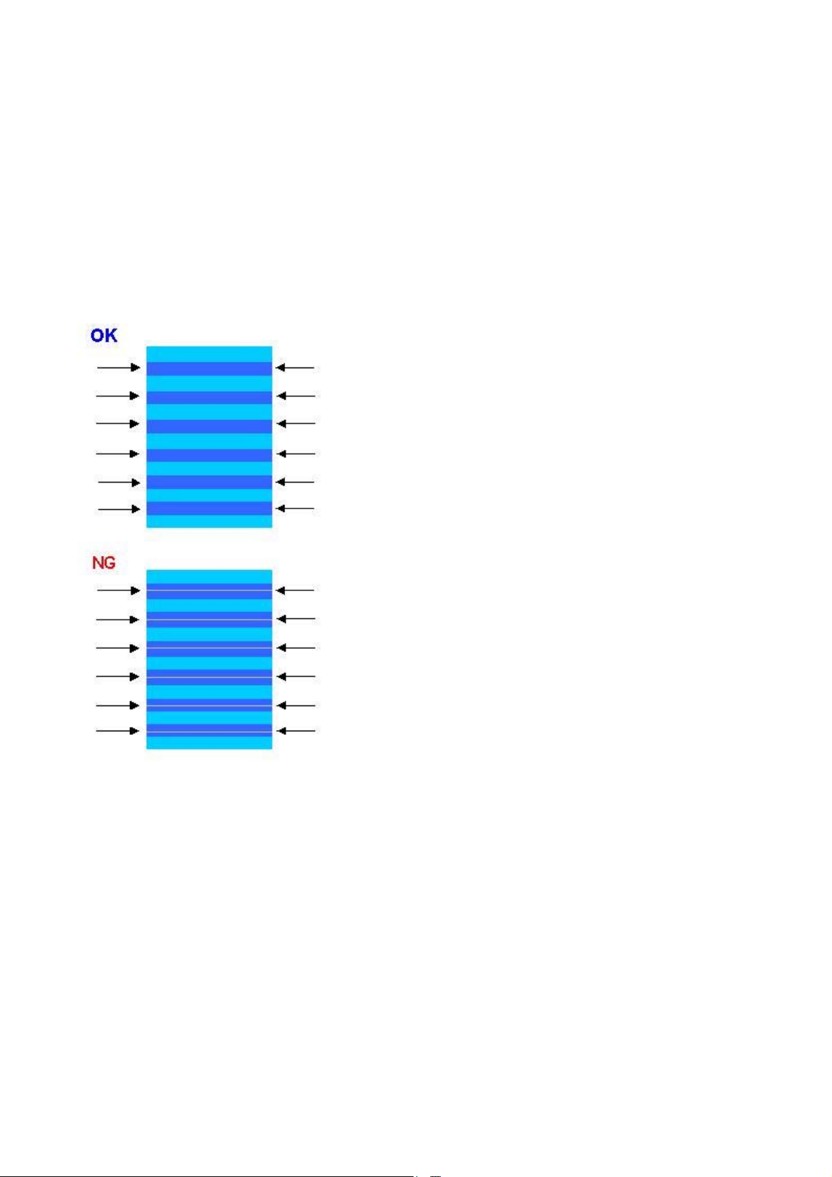
<LF / Eject correction>
37 / 44
After replacement of the feed roller, platen unit, LF encoder, encoder film, or logic board in repair servicing or in refurbishment operation,
perform the adjustment to maintain the optimal print image quality.
1) Print the LF / Eject correction pattern.
Click
LF/EJECT
of paper will be used for the pattern printing.
- Paper source: Select either
- Media type: Select one from
2) When printing is finished, the machine returns to be ready for selection of another function ("Service Mode Idle" is displayed on the LCD).
3) In the printout, determine the Pattern No. in which streaks or lines are the least noticeable for the LF check pattern and the Eject check
pattern respectively. (LF Pattern No. 0 to 4, Eject Pattern No. 0 to 4)
of the Service Tool on the connected computer, select the paper source and the paper type, and print the pattern. 5 sheets
Rear tray
HR-101, GF-500/Office Planner, HP Bright White
or
Cassette
.
, and
Canon Extra/STEINBEIS
.
4) In the LF/EJECT Correction section of the Service Tool, select the Pattern No. (from 0 to 4) determined in step 3) for LF and EJECT
respectively, and click
5) The selected LF and Eject correction values are written to the EEPROM, making the E-MIP correction value (which was set at shipment
from the production site) invalid.
Note: At the production site, the E-MIP correction, which is equivalent to the LF / Eject correction, is performed using the special
tool, and the E-MIP correction value is written to the EEPROM as the valid data.
When LF / Eject correction is performed, the LF / Eject correction values become valid instead of the E-MIP correction
value (thus, in the initial EEPROM information print, "LF = *" and "EJ = *" are printed, but the selected values are printed
after the LF / Eject correction).
Set
.
Page 40
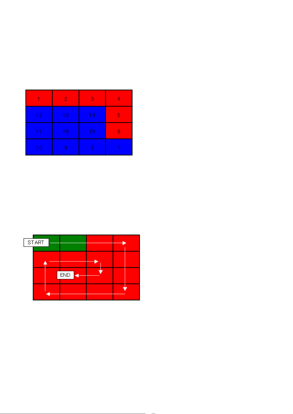
<Button and LCD test>
38 / 44
Confirm the operation after replacement of the operation panel unit, board, or LCD unit.
1) Click
2) Press each button of the operation panel.
3) Only one button should be pressed at one time. If 2 or more buttons are pressed at the same time, only one of them is considered to be
Panel Check
pressed, and the other buttons are ignored.
The LCD is divided into 16 segments, representing each button. The color of a segment corresponding to the pressed button changes to red.
of the Service Tool on the connected computer. The machine LCD turns blue, waiting for a button to be pressed.
1. ON button
2. Back button
3. OK button
4. Up cursor button
5. Down cursor button
6. Left cursor button
7. Right cursor button
8. Black button
9. Color button
10. Stop button
11. NAVI button
12. HOME button
13. Left function button
14. Right function button
15. [+] button
16. [-] button
4) Rotate the Easy-Scroll Wheel clockwise and counterclockwise 1 round (16 steps) each, as follows:
4-1) Rotate the Easy-Scroll Wheel clockwise step by step. The LCD is divided into 16 segments, representing each step. The color of a
segment corresponding to the step changes from red to green.
If the wheel is rotated counterclockwise before clockwise round completes, the color of segment(s) corresponding to the number of
steps the wheel is rotated counterclockwise returns to red.
If the wheel keeps rotated clockwise over 1 round (16 steps), the color of segment(s) corresponding to the extra number of steps returns
to red, starting with the "Start" segment in the figure below.
4-2) When the Easy-Scroll Wheel is rotated clockwise 1 round (16 steps), press the OK button.
Page 41
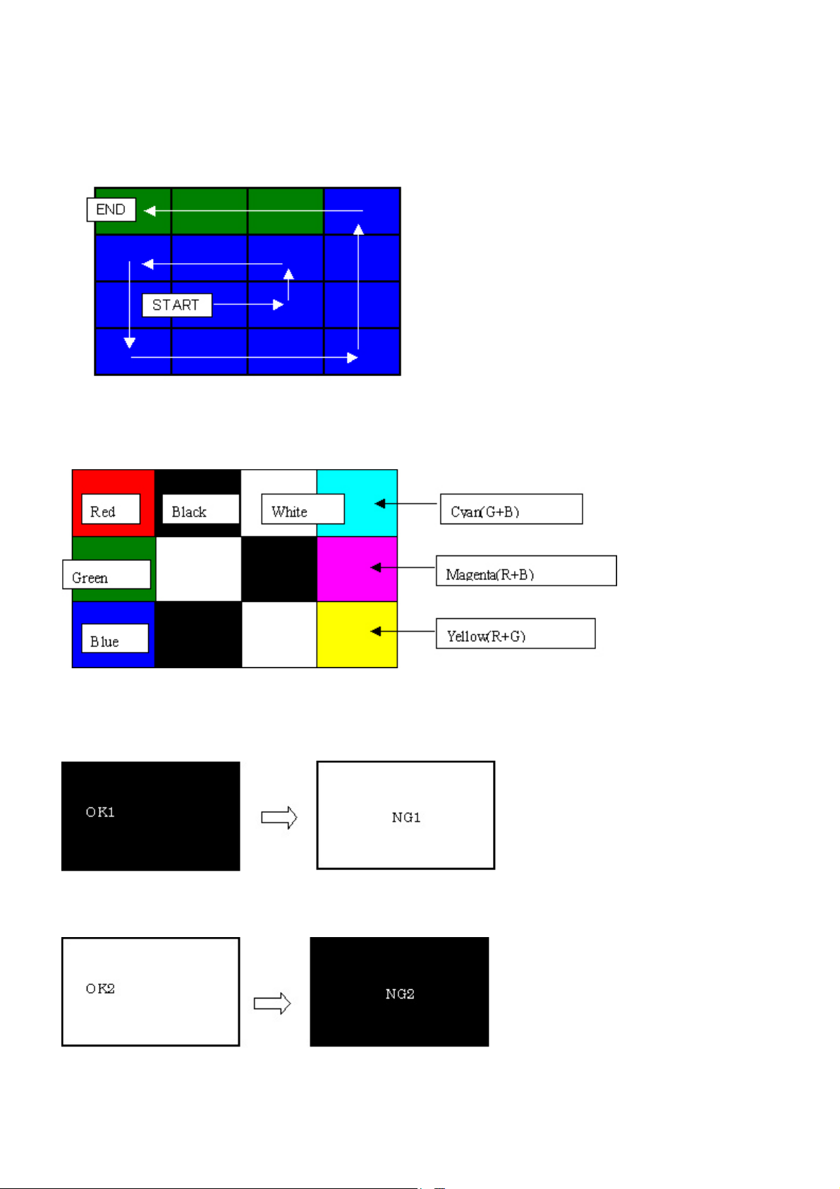
4-3) Rotate the Easy-Scroll Wheel counterclockwise step by step. The LCD is divided into 16 segments, representing each step. The color
39 / 44
of a segment corresponding to the step changes from green to blue.
If the wheel is rotated clockwise before counterclockwise round completes, the color of segment(s) corresponding to the number of
steps the wheel is rotated clockwise returns to green.
If the wheel keeps rotated counterclockwise over 1 round (16 steps), the color of segment(s) corresponding to the extra number of steps
returns to green, starting with the "Start" segment in the figure below.
4-4) When the Easy-Scroll Wheel is rotated counterclockwise 1 round (16 steps, and all the segments are in blue), press the OK button. The
color pattern is displayed on the LCD.
If there is any segment that is not in blue when the OK button is pressed, the display remains unchanged.
5) Adjust the transparent color and LCD flicker, as follows:
5-1) Press the OK button. "OK1" in white is displayed on the black background.
If the result is not good, "NG1" in black is displayed on the white background (transparent color) immediately after "OK1."
5-2) Press the OK button. "OK2" in black is displayed on the white background.
If the result is not good, "NG2" in white is displayed on the black background (transparent color) immediately after "OK2."
5-3) Press the OK button. The machine returns to be ready for selection of another function ("Service Mode Idle" is displayed on the LCD).
Page 42

<Ink absorber counter setting>
40 / 44
Set the ink absorber counter value to a new EEPROM after the logic board is replaced in servicing.
1) Before replacement of the logic board, check the ink absorber counter value in EEPROM information print.
2) After replacement of the logic board, the ink absorber counter value should be set in the service mode using the Service Tool.
In the
Ink Absorber Counter
From the
confirmed before replacement of the logic board, and click
3) Print EEPROM information to confirm that the value is properly set to the EEPROM.
Counter Value(%)
section of the Service Tool, select
pull-down menu, select the value (in 10% increments) which is the closest to the actual counter value
.
Set
Main
from the
<3-3. Adjustment / Settings, (5) and (6)>
Absorber
pull-down menu.
Page 43
MP620 / MP628 --- 3. REPAIR TABLE OF CONTENTS
41 / 44
3-4. Verification After Repair
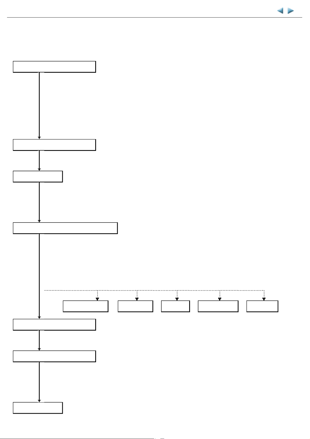
(1) Standard inspection flow
In each step below, confirm that printing is performed properly and the machine operates properly without any strange noise.
EEPROM information print
<Check point>
- The information must be printed properly.
<Additional verification to be made> See 3-1. Notes on Service Part Replacement.
Nozzle check pattern print
Copy function
- At logic board replacement
- At ink absorber replacement
- At platen unit or spur unit replacement
- At operation panel or LCD replacement
- At wireless LAN board replacement
<Check point>
- The pattern must be printed properly.
<Check point>
- Copying must be performed properly.
<Additional verification to be made> See 3-1. Notes on Service Part .
- At document pressure sheet or scanner unit replacement
Communication with a connected computer
<Check point>
- Via USB connection to the computer, printing from the computer must be performed properly
(paper feeding from the rear tray and from the cassette respectively).
Power-off in the service mode
External and internal appearance
<Additional verification to be made>
- For repair of a specific problem, confirm the applicable specific function in the user mode.
PictBridge, IrDA communication, wired or wireless LAN connection, Bluetooth communication,
Scan-to-Memory function, Card Direct printing, etc.
PictBridge, IrDA
<Check point>
- The paper lifting plate must be in the raised position.
<Check point>
- No grease, oil, or smearing on the timing slit strip film.
- No lifting of the platen ink absorber.
- No foreign material or dislocation of any part inside the printer.
- No damage or scratches that will affect the functionality.
LAN, WLAN
Bluetooth
Scan-to-Memory
Card Direct
Packaging
<Check point> See 4. MACHINE TRANSPORTATION.
- The carriage must be locked in the home position.
Page 44
42 / 44
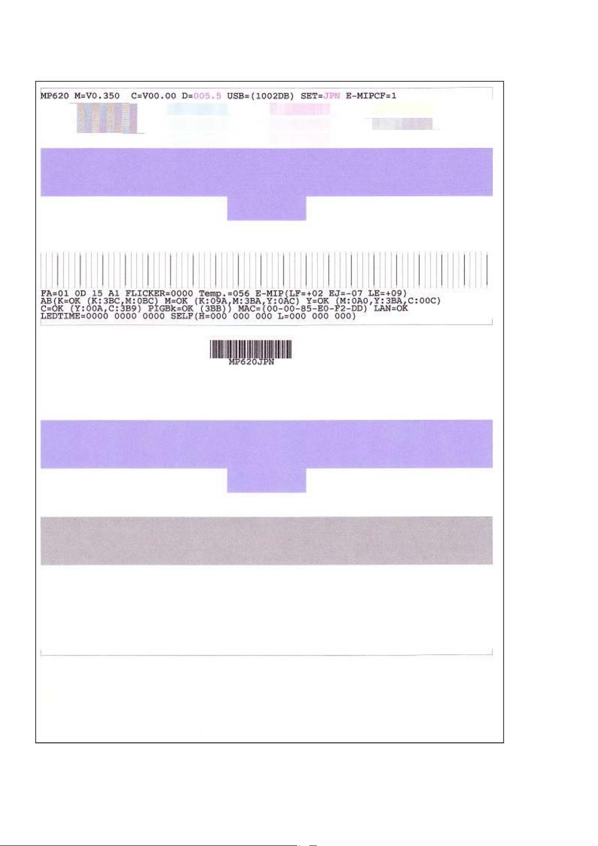
(2) Service test print
<Service test print sample>
Page 45

(3) Ink absorber counter value print
43 / 44
<Print sample>
<3-4. Verification Items>
Page 46
MP620 / MP628 TABLE OF CONTENTS
44 / 44
4. MACHINE TRANSPORTATION
This section describes the procedures for transporting the machine for returning after repair, etc.
1) In the service mode, press the ON button to finish the mode, and confirm that the paper lifting plate of the rear tray is raised.
2) Keep the print head and ink tanks installed in the carriage.
See Caution (1) below.
3) Turn off the machine to securely lock the carriage in the home position. (When the machine is turned off, the carriage is automatically
locked in place.)
See Caution (2) below.
(1) If the print head is removed from the machine and left alone by itself, ink (the pigment-based black ink in
particular) is likely to dry. For this reason, keep the print head installed in the machine even during
transportation.
(2) Securely lock the carriage in the home position, to prevent the carriage from moving and applying stress to the
carriage flexible cable, or causing ink leakage, during transportation.
- If the print head must be removed from the machine and transported alone, attach the protective cap (used when the packing
was opened) to the print head (to protect the print head face from damage due to shocks).
- If the packing material that fixed the carriage from the factory is still available, re-use it to fix the carriage (to prevent the
carriage unlocked during transportation).
<4. MACHINE TRANSPORTATION>
 Loading...