

Canon LV-S3E/D78-5423, LV-S3U/D78-5422 Service Manual
SERVICE MANUAL
English Edition
LV-S3U/D78-5422
LV-S3E/D78-5423
By Portable Document Format
1
General
0
PREFACE
2
Repair
3
Adjustment
4
Troubleshooting
5
Electrical Diagrams
5
Parts Catalog
6
Electrical Diagrams
DY8-1785-421 500

CANON Multimedia Projector
LV-S3U D78-5422
LV-S3E D78-5423
SERVICE
SMANUAL

Technical Documents
Application
This CD-ROM is issued by Canon Inc. for qualified persons to learn technical theory and product
repair. This CD-ROM covers all localities where the products are sold. For this reason, there
may be information in this CD-ROM that does not apply to the product sold in your locality.
The following paragraph does not apply to any countries where such provisions are
inconsistent with local law.
Trademarks
The product names and company names described in this CD-ROM are the registered
trademarks of the individual companies.
Copyright
Canon Inc. retains the copyright to all data contained on this CD-ROM. Reproduction,
publication (including on the World Wide Web) alteration, translation into another language, or
other use of the data in whole or part, contained on this CD-ROM without the written consent of
Canon Inc., is prohibited.
Copyright © 2003 by Canon Inc.
CANON INC.
Camera & Lens Products Quality Evaluation Div.
30-2 Shimomaruko 3-Chome, Ohta-ku,
Tokyo 146-8501, Japan
First published December, 2003

PREFACE
1. Service Manual Composition
This manual contains information on servicing the product. It has the following
sections.
Part 1 General Information
Provides the basic information needed to understand the product.
(Operating instructions are not included. Refer to the product's instruction book if
necessary.)
Part 2 Repair Information
Provides information for disassembly, reassembly, and adjustment of the product, about
the tools required, and their application.
Part 3 Adjustment
Provides information for disassembly, reassembly, and adjustment of the product to
assure precision of the products, about the tools required, and their application.
Part 4 Troubleshooting
Part 5 Parts Catalog
Part 6 Electrical Diagrams
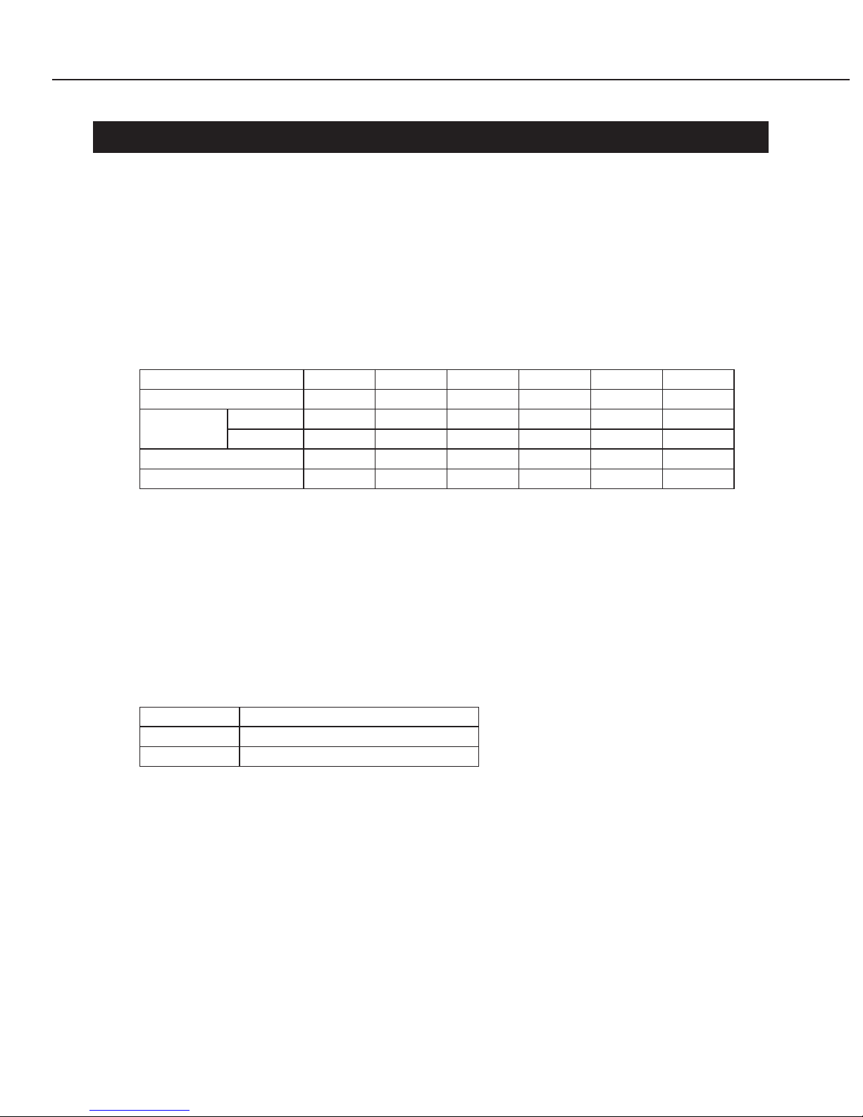
2. Model Differences
In this series of products, there are models suffixed "J", "U", and "E". The only
differences between the models are cosmetic, mainly the designation and rating plates.
Internally, they are identical.
The accessories bundled with the product may differ from country to country.
I
Main Marketing Area
Japan North America Europe
Model Name
POWER PROJECTOR
MULTIMEDIA PROJECTOR MULTIMEDIA PROJECTOR
LV-S3J LV-S3U LV-S3E
3. Tools & Test Equipment
The following tools and equipment are required to perform disassembly, reassembly
and adjustment.
1) Special Tools
None
2) General Purpose Tools (Commercially available, but can be purchased with
the following numbers.)
3) Test Equipment
4) Other Equipment
5) Chart/Software
II
Description Tool No. Specification Remarks
Ball Driver CY9-5002-000 2.0mm Optical Parts Removal
& Adjustment
Hex Key Set CY9-5007-000 2.0mm Optical Parts Removal
& Adjustment
Driver, adjustment CY9-5003-000 1.8mm Electrical Adjustments
Driver, Slot CY9-5004-000 4.0mm
Optical Parts Adjustment
Driver, Cross-point CY9-5005-000 No.2 A
ssembly & Disassembly
Description Tool No. Specification Remarks
Digital Multi-meter Commercially DC1mmV~500V Electrical Adjustment
available
Video Signal Generator
Commercially Color Bars and Gray
Electrical Adjustment
available Scale
Computer Signal Commercially Gray Scale
Electrical Adjustment
Generator available (or personal computer)
Oscilloscope
Commercially 100MHz response or Waveform Checks and
available over Electrical Adjustment
Description Tool No. Specification Remarks
Screen
Commercially Over 40"
All Adjustment
available
Personal Computer
Commercially
Windows 95 OS All Adjustment
available
Description Tool No. Specification Remarks
Monitor Tester Supplied with manual All Adjustment
Gray Scale Chart Supplied with manual Bitmap Data All Adjustment
Common Center
Supplied with manual
(SVGA) Common Center
Adjustment Chart Adjustment
Color Shading
Supplied with manual Ver. 3.02
White Uniformity
Correction Tool Adjustment

CONTENTS
Page
Part 1: General Information
1. FEATURES ...................................................................................................... 1-1
1.1 Development Objective ............................................................................ 1-1
1.2 Product Overview .................................................................................... 1-1
1.3 Main Features .......................................................................................... 1-2
2. SPECULATIONS ............................................................................................. 1-3
2.1 Type ......................................................................................................... 1-3
2.2 LCD Panels .............................................................................................. 1-3
2.3 Optics ....................................................................................................... 1-3
2.4 Images ..................................................................................................... 1-3
2.5 Video Signals ........................................................................................... 1-3
2.6 Mechanisms ............................................................................................. 1-4
2.7 Connectors .............................................................................................. 1-4
2.8 Ratings ..................................................................................................... 1-4
3. FUNCTIONS .................................................................................................... 1-5
3.1 Optics ....................................................................................................... 1-5
3.2 Images ..................................................................................................... 1-5
3.3 Input Signals ............................................................................................ 1-7
3.4 Mechanisms and Systems ....................................................................... 1-8
3.5 Connectors .............................................................................................. 1-9
4. ACCESSORIES ............................................................................................... 1-10
4.1 Principal Accessories ............................................................................... 1-10
4.2 Replacement Parts .................................................................................. 1-10
4.3 Opitional Parts ......................................................................................... 1-10
5. PRECAUTIONS ............................................................................................... 1-11
6. DESCRIPTION ................................................................................................ 1-12
6.1 Optics ....................................................................................................... 1-12
6.2 Images ..................................................................................................... 1-13
6.3 Image Signals .......................................................................................... 1-13
6.4 Mechanisms and Systems ....................................................................... 1-13
6.5 Design ...................................................................................................... 1-14
Part 2: Repair Information
1. SAFETY INSTRUCTIONS ............................................................................... 2-1
2. CIRCUIT PROTECTIONS ............................................................................... 2-2
2.1 Fuse ......................................................................................................... 2-2
2.2 Thermal Switch ........................................................................................ 2-2
2.3 Lamp Cover Switch .................................................................................. 2-3
2.4 Warning Temperature and Power Failure Protection .............................. 2-3
2.5 Air Filter Care and Cleaning .................................................................... 2-4
3. MECHANICAL DISASSEMBLIES .................................................................... 2-5
III

3.1 Side Panel Removal ................................................................................ 2-5
3.2 Cabinet Top Removal .............................................................................. 2-5
3.3 Main Board Removal ............................................................................... 2-6
3.4 Rear Panel, AV Board and FN903 Removal ........................................... 2-6
3.5 Thermal SW Removal .............................................................................. 2-7
3.6 Optical Unit Removal ............................................................................... 2-7
3.7 Cabinet Front, R/C Board and Speaker Removal .................................... 2-8
3.8 Power Unit and FN906 Removal ............................................................. 2-8
3.9 Lamp Ballast Unit and Filter Board Removal ........................................... 2-9
3.10 FN904 Removal ..................................................................................... 2-9
3.11 FN902, FN905 and Sensor Board Removal .......................................... 2-10
3.12 FN901 and Lamp Cover SW Removal .................................................. 2-10
4. OPTICAL PARTS DISASSEMBLIES ............................................................... 2-11
4.1 Lamp Holder Removal ............................................................................. 2-11
4.2 Projection Lens Ass'y Removal ............................................................... 2-11
4.3 Polarized Glass-In Removal .................................................................... 2-12
4.4 Optical Unit Top Removal ........................................................................ 2-12
4.5 Locations and Directions ......................................................................... 2-13
5. LCD PANEL/PRISM ASS'Y REPLACEMENT ................................................. 2-14
5.1 LCD Panel/Prism Ass'y Removal ............................................................. 2-14
5.2 LCD Panel/Prism Ass'y Attachment ......................................................... 2-14
6. CLEANING ....................................................................................................... 2-15
7. LAMP REPLACEMENT ................................................................................... 2-16
Part 3: Adjustment
1. ELECTRICAL ADJUSTMENTS ....................................................................... 3-1
1.1 Adjustments after Parts Replacement ..................................................... 3-1
1.2 Service Adjustment Menu Operation ....................................................... 3-2
1.3 Service Adjustment Data Table ............................................................... 3-3
2. CIRCUIT ADJUSTMENTS ............................................................................... 3-7
2.1 PC Pedestal Adjustment .......................................................................... 3-8
2.2 PC Gain Adjustment ................................................................................ 3-8
2.3 Video Gain Adjustment ............................................................................ 3-9
2.4 480p Pedestal Adjustment ....................................................................... 3-9
2.5 480p Gain Adjustment ............................................................................. 3-10
2.6 480i Gain Adjustment .............................................................................. 3-10
2.7 Gamma Adjustment ................................................................................. 3-11
2.8 Common Center Adjustment ................................................................... 3-11
2.9 White Balance Adjustment ....................................................................... 3-12
2.10 Note On White Uniformity Adjustment ................................................... 3-12
3. OPTICAL ADJUSTMENTS .............................................................................. 3-13
3.1 Contrast Adjustment ................................................................................ 3-13
3.2 Condenser Lens Adjustment ................................................................... 3-14
3.3 Relay Lens-Out Adjustment ..................................................................... 3-15
4. TEST POINTS AND LOCATIONS ................................................................... 3-16
IV

Part 4: Troubleshooting
1. TROUBLESHOOTING ..................................................................................... 4-1
1.1 No Power ................................................................................................. 4-1
1.2 No Picture ................................................................................................ 4-4
1.3 No Sound ................................................................................................. 4-6
2. CONTROL PORT FUNCTIONS ...................................................................... 4-7
2.1 System Control & I/O Port Table (IC301) ................................................ 4-7
2.2 IIC Bus D/A Converter (IC3551, M62393FP) ........................................... 4-8
2.3 IIC Bus D/A Converter (IC3561, M62392FP) ........................................... 4-9
2.4 IIC Bus D/A Converter (IC3571, M62392FP) ........................................... 4-9
2.5 Sub CPU (IC1882, PIC12F675) ............................................................... 4-10
2.6 Output Expander (IC1801, TC74LCX574FT) .......................................... 4-10
2.7 Output Expander (IC1802, TC74LCX574FT) .......................................... 4-10
2.8 Input Expander (IC1811, TC74LCX541FT) ............................................. 4-11
3. WAVEFORMS ................................................................................................. 4-12
4. IC BLOCK DIAGRAMS .................................................................................... 4-13
Part 5: Parts Catalog
Part 6: Electrical Diagrams
1. PARTS DESCRIPTION AND READING IN SCHEMATIC DIAGRAM.............. 6-1
2. DIODE, TRANSISTOR AND IC PINS............................................................... 6-3
Chassis Block Diagrams ................................................................................... 6-4
Power Supply Lines .......................................................................................... 6-7
Schematic Diagrams ......................................................................................... A3
Printed Wiring Board Diagrams......................................................................... A7
V

Part 1
General
Information
1. FEATURES
1.1 Development Objective
The market for SVGA projectors is large compared to that for other models, and is of
major importance. However, drastic price cuts are affecting the entire market, and the
competitiveness of current models is declining.
In response, Canon decided to develop a new compact, low-price model. Employing its
original optical technologies, Canon has developed a micro-portable-class model
featuring compact and high brightness that will enable Canon to expand its market
share.
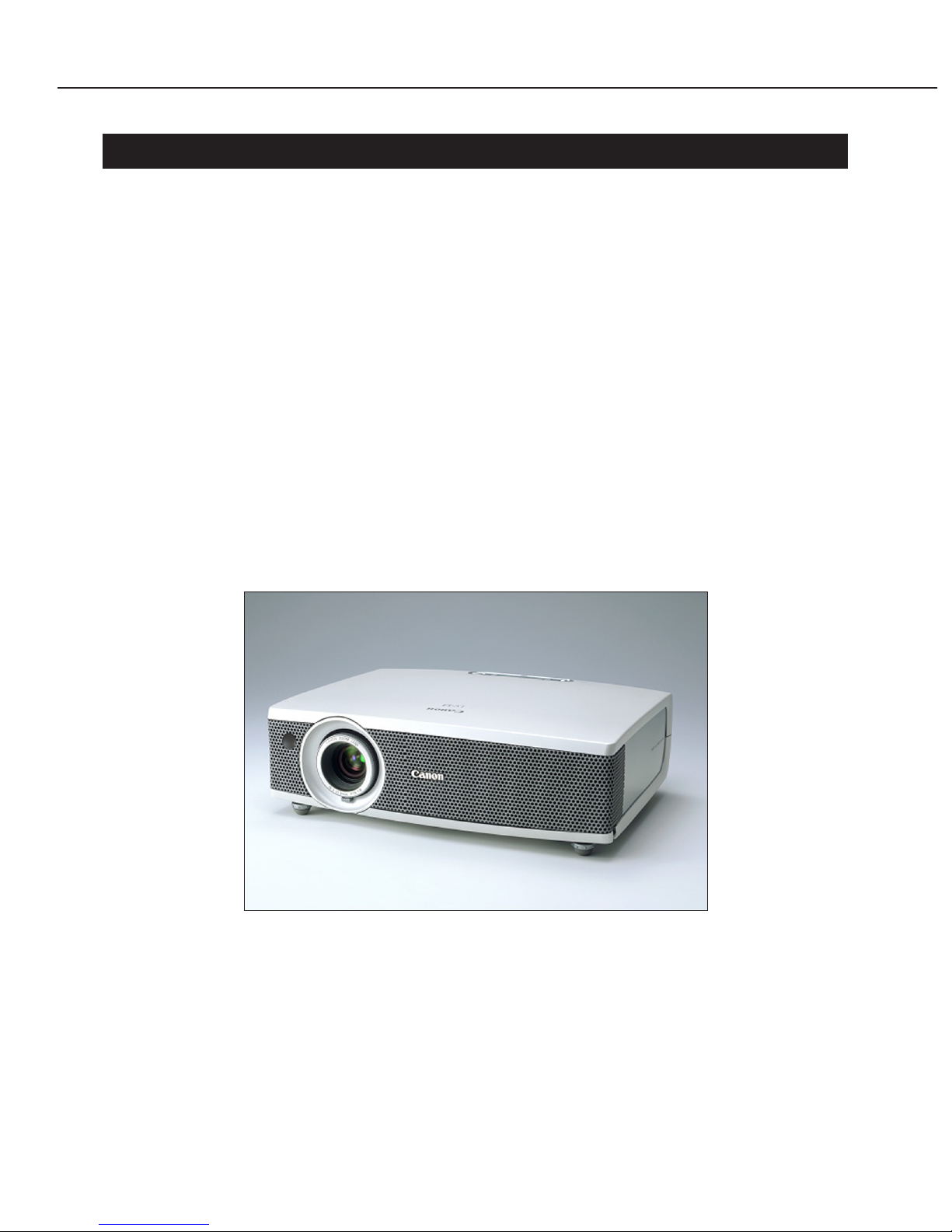
1.2 Product Overview
The LV-S3, the successor to the LV-S2, is an SVGA micro-portable-class projector.
Incorporating Canon's original optical box and first 0.5-inch liquid-crystal panels, this
B5-file size projector weighs just 2.2 kilograms (2% reduction in volume and 25%
reduction in weight). Moreover, this outstanding cost-performance projector features a
high brightness of 1,250 lumens.
Part 1: General Information
1-1
Fig. 1-1

1.3 Main Features
● B5-file size weighing 2.2 kg and active design
Use of 0.5-inch liquid-crystal panels made it possible to reduce the size and weight of
the entire optical box, while the compact body has kept the weight down to 2.2 kg.
The combination of "Frosty Pearl White" coloring and precision coating technology
conveys the product's high quality and lightness.
● 1.2× wide zoom lens capable of 100-inch projection at 3.2 meters
The projector's new compact lens, which was developed by Canon, employs two both
sided aspherical lenses to achieve both compactness and high image quality. Capable
of 100-inch projection at 3.2 meters, the projector produces high-quality images with
minimal color bleeding.
● 1,250-lumen, 0.5-inch SVGA panel
The projector incorporates Canon's first 0.5-inch liquid crystal panels. Brightness of
1,250 lumens is produced by means of microlenses to boost condensing and a 160-
watt UHP lamp.
● Progressive scan
Not only composite signals but also 480i/575i component signals are converted to
progressive display, resulting in high-quality video playback. And the newly designed
image processing circuit delivers outstanding image quality.
● 32-decibel Silent mode and Auto mode
There are three lamp modes for brightness: Normal (regular output), Silent (low
output) and Auto (automated control). These can be selected according to use: Normal
to give priority to brightness, Silent to keep fan noise down to 32 decibels, and Auto to
adjust the brightness in accordance with the displayed image.
● Presentation remote control unit
The projector comes with a separate presentation remote control unit for operating
presentation functions and a separate remote control unit for operating the projector.
This remote control unit eliminates the complexity of having all functions
concentrated in one remote control unit, thus ensuring smooth presentations.
Part 1: General Information
1-2

2. SPECULATIONS
2.1 Type
1. Type Projector
2. Product class Micro portable class
3. Imaging Device Transmissive type LCD panel
2.2 LCD Panels
1. Drive system Polysilicon-TFT active matrix
2. Micro-lens Attached
3. Size, Number 11.2mm × 8.5mm (0.5'' type, aspect ratio 4:3),
3 panels
4. Number of pixels 480000 pixels (800 × 600, SVGA)
2.3 Optics
1. System Dichroic-mirror color separation and cross-prism
color composition
2. Light source 160W UHP lamp
3. Projection lens 9 groups 9 elements
4. F number, Focal length F1.6 to 1.8, f = 18.3 to 21.9mm
5. Zoom/Focus 1.2-times manual-operated zoom/manual-operated
focus
6. Lens shift 9:1, fixed
2.4 Images
1. Brightness (Normal) 1250lm; Marginal luminance ratio: 85%
2. Contrast ratio 300:1 (100% white: 100% black)
3. Projection distance coverage 1.3 to 6.5m (100'' type: 3.2 to 3.8m)
4. Projected screen size 34" type (0.69m × 0.52m) to 200" type
(4.06m × 3.05m)
5. Electronic zoom ×0.5 to ×16 (SVGA)
6. Keystone correction Up-down direction ±20°
2.5 Video Signals
1. Analog RGB XGA (compressed)/SVGA/VGA
2. Composite/S-Video Color system: NTSC/PAL/SECAM/NTSC4.43/
PAL-M/PAL-N
3. Component Scanning system: 1080i/1035i/720p/575p/575i/
480p/480i
4. Scanning frequency Horizontal: 15 to 80kHz, Vertical: 50 to 100Hz;
Dot clock: 100MHz
Part 1: General Information
1-3
2.6 Mechanisms
1. Adjustable feet Can be adjusted to raise the main unit a maximum
of 8°
2. Built in speaker 0.8W, Monaural
2.7 Connectors
1. Mini Dsub 15-pin Analog RGB/Component video/SCART
2. RCA × 1 Composite video
3. S connector (min DIN 4) S-video
4. Stereo mini-pin jack 1 Audio input (for image by Mini Dsub 15-pin)
5. Stereo mini-pin jack 2 Audio input (for image by RCA × 1 or S connector)
6. USB connector (type B) USB port
7. Service connector Connector used for servicing the projector
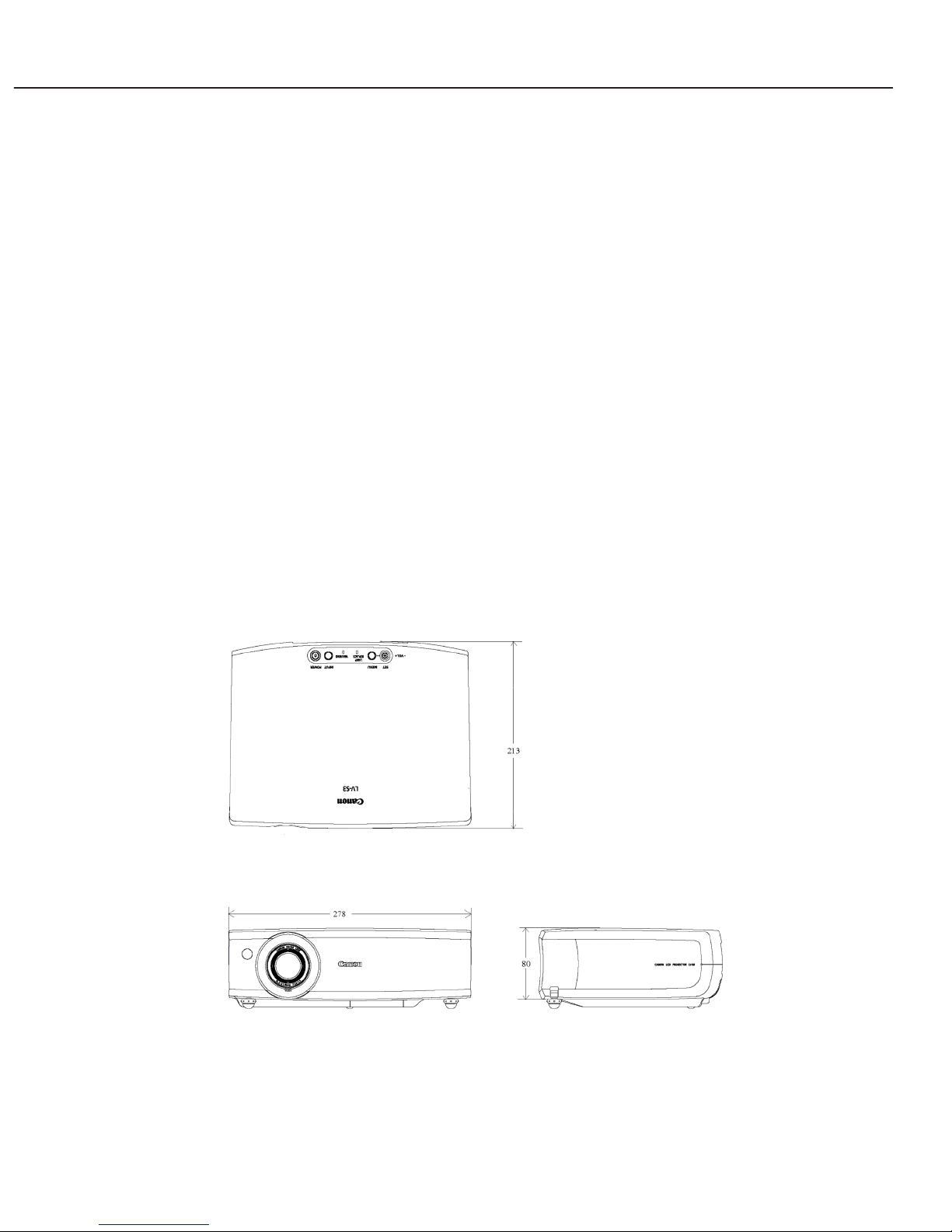
2.8 Ratings
1. Dimensions W: 278mm, D: 213mm,
H: 80mm (See Outline Drawings)
2. Weight 2.2kg
3. Power Source J: 100V / U: 100 to 120V / E: 200 to 240V; 50/60Hz
4. Power consumption Normal mode: 244/Silent mode: 169W
5. Noise Normal: 32dB A/Silent: 32dB A
6. Operating temperature range 5 to 35°C
7. Storage temperature range –10 to 60°C
Part 1: General Information
1-4
Fig. 1-2
3. FUNCTIONS
3.1 Optics
● Zoom and focus
The zoom ratio of the projection lens of this product is 1.2-times.
Both the zoom and focus can be adjusted manually.
● Projection distance and projection screen size
These products are capable of projecting accurately at distances between 1.3 and 6.5
meters.
Note that the displayable screen size ranges from 34 to 200 inches.
* The quantities H1 and H2 represent heights of the top section and bottom section of the
screen if the screen is divided vertically along a line level with the projector's lens axis. The
ratio of H1 to H2 is 9:1.
3.2 Images
● Image mode selection [IMAGE]
This function makes it possible to select γ characteristics in accordance with image
content.
The following image modes are available according to the input type.
• Standard
This setting works with general computer and VCR video.
• High contrast (for computer input)
This mode brightens dark and mid-range areas making the overall image appear
brighter.
The High-contrast Mode can reproduce entire images clearly even in brightly lit
environments.
• Cinema (for video input)
This mode boosts dark areas, improving the reproduction of dark pictures.
In effect, this improves the expressiveness of scenes with many dark areas,
common in movies, by preventing black saturation.
Part 1: General Information
1-5
0.69×0.52
–
1.29
47
5
Size [m]
Zoom min
Zoom max
Projection
Distance [m]
Screen 34"
0.81×0.61
1.28
1.53
55
6
40''
2.03×1.52
3.23
3.84
137
15
100''
3.05×2.29
4.85
5.78
206
23
150''
3.43×2.58
5.47
6.51
232
26
169''
4.06×3.05
6.48
–
274
31
200''
H1 [cm]
H2 [cm]
Input Image mode
Standard/High contrast/Custom
Standard/Cinema/Custom
Computer
Video

• Custom
In this mode, users can make various video adjustments, based on one of the
previous modes, to suit their personal preferences. Users can also store their
Custom Mode settings.
● Keystone correction [KEYSTONE]
Keystone correction is a function that digitally compensates for deformations in the
picture shape caused by the placement of the projector. This compensation is
adjustable ±20 degrees vertically.
● Digital zoom [D.ZOOM]
This function electrically scales a selected region of the picture.
The region can be projected at anywhere between 0.5 and 16 times its normal size.
● Freeze [FREEZE]
This function temporarily pauses an image projection.
● No image projection [NO SHOW]
This function temporarily shuts off the image projection.
● Presentation timer [P-TIMER]
This function displays the elapsed time as a counter on the image.
● Auto-Grayscale
Provides a clear picture for night scenes and other dark or low-contrast images. When
this function is selected, it automatically controls the picture signal output to
maximize the whiteness and blackness levels of output images.
● Progressive display
Performs signal conversion when video image signals from interlace scanning are
input, and automatically provides progressive display. Accommodates composite, Svideo and 480i/575component signals.
Can be set to OFF, L1 (for animated images) or L2 (for stills).
* When progressive display is used, unnatural noise can occur in quickly moving
objects.
If this is distracting, this function can be turned off.
● Start-up screen customization (logo capture)
This function allows users to select a still image as the start-up screen.
Users can capture an image during projection and use that image as the start-up
screen.
● Reverse image
This function allows the projected image to be reversed horizontally or vertically.
When rear projection is selected, the projector projects images reversed horizontally.
When ceiling mount is selected, the projector projects images reversed both
horizontally and vertically.
Part 1: General Information
1-6

● Blue back display
This function automatically displays a solid-blue background when there is no input
signal.
3.3 Input Signals
● Computer input
Accommodates SXGA, XGA, SVGA, VGA and MAC analog RGB inputs.
For SXGA, XGA and some MAC inputs, the display is compressed.
* About the detail of computer input, they are not explained separately. (Refer to
Owner's Manual)
• Multi-scan system
The projector recognizes the horizontal and vertical frequencies of the image signal
from the connected computer and automatically selects the corresponding display
system.
• Automatic PC adjustment function
Automatically adjusts the following four items on screen to the correct values: total
dots, fine sync, horizontal position, and vertical position.
Select Auto to automate these adjustments with just one touch.
Each item can also be adjusted manually. When items cannot be completely
adjusted automatically or in similar cases, manual adjustment can be used for finetuning.
● Component video input
• Scanning system
This product supports 1080i, 1035i, 720p, 575p, 575i, 480p, and 480i. (auto and
manual selection)
● Composite video input or S-Video input
• Color systems
This product supports NTSC, PAL, SECAM, NTSC 4.43, PAL-M, and PAL-N.
When this function is set to Auto and a color format is input, the format will be
accommodated automatically (excluding PAL-M and PAL-N).
● SCART input (Requires LV-CA31, the optional conversion cable)
Enables the analog RGB input (Dsub-15) terminal to receive image signals from the
video equipment's SCART terminal.
Part 1: General Information
1-7
3.4 Mechanisms and Systems
● Lamp mode selection
This function selects the power consumption of the lamp.
Normal mode is appropriate when brightness is top priority, such as for large meeting
rooms (large-screen projection) or for locations that cannot be made dark enough.
Silent mode is appropriate for minimizing the noise level when meeting rooms (and
screen sizes) are small and there is sufficient light.
Auto mode automatically changes the lamp output according to the image content,
emphasizing the display of black, such as for dark animated scenes.
● Adjustable feet
At the lower-front of the unit, on the same side as the projection lens, there are two
adjustable feet for elevating the unit, so the projector can be tilted for projection. Up
to eight angles of elevation can be set between the optical projection axis and the
surface on which the projector is placed.
Releasing the lock on the adjustable feet with just one touch enables the leg to be
retracted back inside the unit.
* By using the keystone correction function described previously, the trapezoidal
distortion occurring during projection at an incline can be eliminated.
● Audio Mute [MUTE]
This function temporarily turns off the output to the speaker.
* The projectors have a built-in 0.8-watt speaker. Audio from computers or VCRs is
played back in mono.
● Power management
This function turns the lamp off if no video signal is input or projector operation
performed for a preset period.
This duration can be set between one and 30 minutes.
When the lamp has been turned off with power management, it will automatically turn
on when a video signal is input again or a projector operation performed. (Note that
the lamp will not turn on during the 90-second cool down period effective immediately
after being turned off.)
Part 1: General Information
1-8
Mode Normal Silent Auto
Lamp power 160W 120W Automatic control
Brightness 1250lm 900lm (72% of normal) Automatic control
Noise level 37dB A 32dB A Variable
● Graphical user interface
The graphical user interface allows users to make adjustments easily while watching
the display on the screen.
* The display language can be selected from one of 12 languages (English, German,
French, Spanish, Italian, Portuguese, Dutch, Swedish, Chinese, Korean, Russian,
and Japanese).
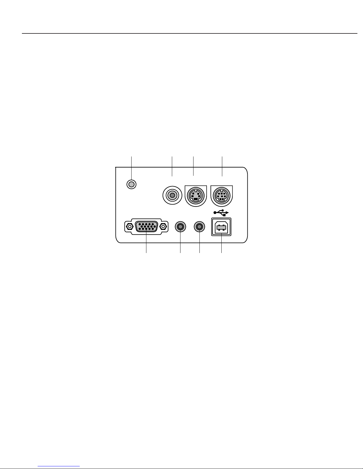
3.5 Connectors
The inputs connectors and other are located on the back of the projector.
● Image input
[1] Mini Dsub 15-pin Analog RGB/Component video/SCART
[2] RCA × 1 Composite video
[3] S connector (min DIN 4) S-Video
● Audio input
[4] Mini-pin jack Stereo for image inputs [1]
[5] Mini-pin jack Stereo for image inputs [2] and [3]
* The built-in speaker provides only mono output.
● Control
[6] USB connector (type B) USB port
[7] Service connector Connector used for servicing the projector
● Others
[8] Reset button Used to restart the projector when its operation
becomes unstable
Part 1: General Information
1-9
S-VIDEO IN
RGB IN
/
COMPONENT INCOMPONENT IN
COMPUTERCOMPUTER
/
COMPONENTCOMPONENT
AUDIO IN
VIDEO INVIDEO IN
SERVICE PORT
RESET
AUDIO
IN
[8] [2] [3] [7]
[1] [4] [5] [6]
Fig. 1-3

4. ACCESSORIES
4.1 Principal Accessories
● Remote control unit (wireless)
Used to turn on the projector and operate its various functions.
● Presentation remote control unit (wireless) and receiver
This remote control limits the functions to those for presentation and PC functions
such as page-turning and mouse control.
* Connect a presentation remote controller receiver to the USB terminal of the PC
when the presentation remote controller is used.
For projector functions, the presentation remote control should be pointed at the
projector. For PC functions, it should be pointed at the receiver.
● Computer connection cable (Dsub15-Dsub15)
This cable is used to input analog RGB video signals from computers and other
devices.
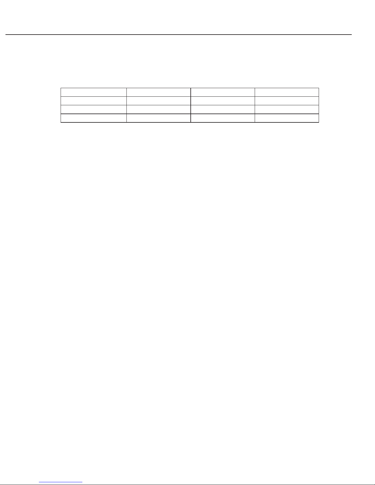
4.2 Replacement Parts
● Canon's replacement lamp: LV-LP20
The LV-LP20 is only ready for the LV-S3.
An indicator will light when the lamp should be replaced.
Recommended lamp replace time:
* This time guarantees a 50 percent survival rate and a 50 percent brightness-maintenance rate.
4.3 Optional Parts
● SCART-VGA cable LV-CA3
Use when connecting to the video apparatus with SCART output terminals.
● 3RCA-Dsub15 cable LV-CA32
This cable is used to connect the projector with devices with component outputs (RCA
× 3).
● Canon ceiling mount LV-CL09
This mounting bracket is used to hang the projector from a ceiling.
* Make sure to use LV-CL09 when the projector is to be installed in a ceiling, and after
deciding the location, ensure the installation work is done by a professional.
Part 1: General Information
1-10
Input Normal mode Silent mode
LV-LP20 2000 hours 2500 hours

5. PRECAUTIONS
● Do not unplug the projector after turning off the lamp until the cooling fan stops.
Not allowing the projector to cool sufficiently may damage the unit.
* The hot lamp will cause burns. Wait at least 45 minutes after the fan stops before
replacing the lamp.
● Do not look directly at the projection lens when it is in operation.
The projection is very bright and can damage eyesight.
● Replace the lamp with a new lamp promptly when lamp replacement is indicated.
A high-pressure mercury lamp is used as the projector's light source. Due to the
characteristics of the mercury lamp, it may burst because of deterioration over long
use.
Should the lamp burst, we recommend that you return the projector to the store
where you purchased it to have the lamp replaced and the unit inspected.
● Do not use the projector when tilted excessively.
Place the projector on surfaces with a horizontal slant of no more than ±20 degrees.
Due to the characteristics of the mercury lamp, using the projector at an excessive
inclination may cause the lamp to operate abnormally or shorten its service life.
The projector was not designed to be used while tilted; therefore, use the projector on
a level surface whenever possible.
Part 1: General Information
1-11

6. DESCRIPTION
6.1 Optics
The optical system employs a compact zoom lens, 0.55-type (0.5-type, nominally)
liquid-crystal panels with microlenses, an internal optical system optimized for panel's
size and a 160-watt UHP lamp.
This optical system is the key behind this compact, micro-portable projector.
Disapproval to reproduce optical drawing
● 1.2× compact zoom lens
This 1.2× projection lens has a negative-positive-positive-positive-positive 5-group
zoom (with 3 groups mobile) based on a 9-group 9-element lens configuration.
The use of two both sided aspherical lenses (G2 and G8) from plastic mold has
decreased the front-bead diameter and number of lenses.
These features have resulted in a compact, wide-angle lens that produces high image
quality with minimal aberration and the like.
All of the materials used for the lenses are lead-free.
● Screen size
This product can display images with excellent fidelity on 100-inch screens at a throw
distance of 3.2 meters.
Refer to the table below for the relationship between the throw distance and the screen
size.
* The projector displays correctly at screen sizes between 34 and 200 inches; the quality of projections at other screen
sizes is not guaranteed.
● Internal optical system
For the prism that engages in color composition, a low-volume cross prism is used to
make the optical box compact.
To counteract heat, sapphire bases are used for part of the boards that attaches the
polarizer.
● Liquid crystal panels
This 0.55-inch liquid crystal panels are the transmissive type. With the same number
of pixels as in a real SVGA display, the aperture ratio is 48%; the addition of microlenses increases the efficiency of light utilization.
● Lighting system
A 160-watt UHP lamp with 1 mm arc length is used for the lighting system. This lamp
also has a longer service life than the conventional lamps.
The design of the pair of luminosity leveled elements (fly eye integrator) right after the
first emission of the lamp has been optimized, thus greatly improving the efficiency of
light utilization.
Part 1: General Information
1-12
1 m
26.4 - 31.4
Distance
Screen size
2 m
52.3 - 62.2
3 m
78.1 - 93.0
4 m
104 - 124
5 m
130 - 155
6 m
156 - 185
7 m
182 - 216
8 m
198 - 313

Although the projection lens's zoom ratio of 1.2× for the LV-S3 is less than the 1.4×
for the LV-S2, the length and diameter are both 81% that of LV-S2, thus greatly
improving compactness.
Similarly, the optical box was also made smaller and lighter.
6.2 Images
Auto-grayscale, progressive display and logo capture were added as new features for
the LV-S2. All were achieved by improving the hardware specifications of the electrical
circuit.
As these features are not new to the LV series, they are not explained separately.
* The LV-5200 comes with auto-grayscale; the LV-7215, 7210 and 5210 come with
progressive display and logo capture.
6.3 Image Signals
Although SCART input is a new function for the LV-S2, it is already provided in
products in other classes. It remains the standard input for the LV series at present,
and so is not explained separately.
* The LV-7555, 7215, 7210 and 5210 come with SCART input.
6.4 Mechanisms and Systems
● Heat and noise countermeasures
This projector is equipped with a main exhaust outlet on the front (left) and a
secondary exhaust outlet on the back (right).
The main exhaust outlet uses the air intake from the inlet on the back on the left to
cool mainly the lamp, and then exhausts the air.
The secondary exhaust outlet cools mainly the liquid-crystal panels and power unit,
and then exhausts the air.
The main exhaust outlet exhausts diagonally above and to the left (away from the
lens), which prevents the heat exhaust from meeting the projected light, which would
generate heat haze. As some loss is incurred by the diagonal emission, however, a
secondary outlet has been provided to supplement the cooling effect of the main
exhaust.
The main and secondary fan rotational speeds have been optimized in consideration
of internal heat distribution and noise balance.
Part 1: General Information
1-13
6.5 Design
By balancing a layout that focuses on compactness and lightweight, heat
countermeasures for achieving high brightness and stylish presentation, Canon has
created a projector that can be easily used everywhere from offices that are bright with
outside light to "home theaters" for enjoying movies.
● Styling
With its simple modeling elements and air-style form achieved with clean surface
composition, the product is clearly distinct from other companies' products in the lowprice, compact, lightweight class.
● Coloring
A new body color, "Frosty Pearl White," was achieved with a two-coat process in which
the top coat is applied so that the base coat can be seen underneath. This highquality, transparent finish has excellent durability, even under long-term use.
● Details
The main exhaust outlet, which is responsible for most of the heat and fan noise, is
positioned on the front, away from people, and the cover gives an appearance of
stylish precision.
Along with the simple back so that the user can concentrate on the pictures that have
been taken, the interface system and cables have been unified so that the area around
the projector is not distracting.
Part 1: General Information
1-14
Main Exhaust Vent
Sub Exhaust Vent
Fig. 1-4

Part 2
Repair
Information
Part 2: Repair Information
2-1
1. SAFETY INSTRUCTIONS
The following precautions must be observed during servicing and inspection.
Observe all safety precautions.
Comply with all caution and safety-related notes provided on the cabinet back, cabinet
bottom, inside the cabinet, on the chassis or components, as well as the precautions
shown in the instruction manual during servicing.
Avoid electric shock.
Since an AC voltage is applied to the chassis for the set, touching the chassis during
power-on may cause electric shock. When service is performed during power on, use an
insulation transformer, wear protective gloves, and remove the plug during parts
replacement. As there are high-voltage areas inside the projector, handle it with care
when the power is on.
Use specified parts.
The parts of the set have safety properties, such as inflammability and voltage
withstand. Therefore, use replacement parts with the same characteristics as the
original ones. The critical components for safety are indicated by mark in the schematic
diagram and parts list must be replaced by the recommended parts.
Reinstall parts and wires in their original positions.
Insulating materials, such as tubes and tape, are used and some components are
installed over a PC board for safety. Reinstall internal wires with clamps so that they do
not touch any heat-generating or high-voltage parts.
Safety c
heck after service
Verify that service locations are not deteriorated and all removed screws, parts and
wires are installed in their original positions. In addition, perform the following test to
ensure safety.
Insulation resistance test method
Remove the plug from the electric outlet and press the power switch. Using a 500V
insulation resistance tester (or a multimeter if any insulation resistance tester is not
available), check that the insulation resistance between each terminal of the plug and
external exposed connector (external speaker connector, remote control connector, AV
input/output connector, etc.) is 1Mohm or higher
. If not, the set must be inspected and
repaired.
Components indicated by mark in the parts list and the schematic diagram designate components in
which safety can be of special significance. It is, therefore, particularly recommended that the
replacement of there parts be made by exactly the same parts. Using unspecified parts may worsen
failure or cause fire or electric shock.
Eye damage may result from directly viewing the light produced by the lamp used in this equipment.
Always turn off the lamp before opening the cover.
Never turn the power on without the lamp to avoid electric shock or damage of the devices since the
stabilizer generates high voltages (15kV - 20kV) at its starts.
Since the lamp is very high temperature during units operation replacement of the lamp should be done at
least 45 minutes after the power has been turned off, to allow the lamp cool-off.
Precautions for servicing
Part 2: Repair Information
2-2
2. CIRCUIT PROTECTIONS
This projector provides the following circuit protections to operate in safety. If the
abnormality occurs inside the projector, it will automatically turn off by operating one of
the following protection circuits.
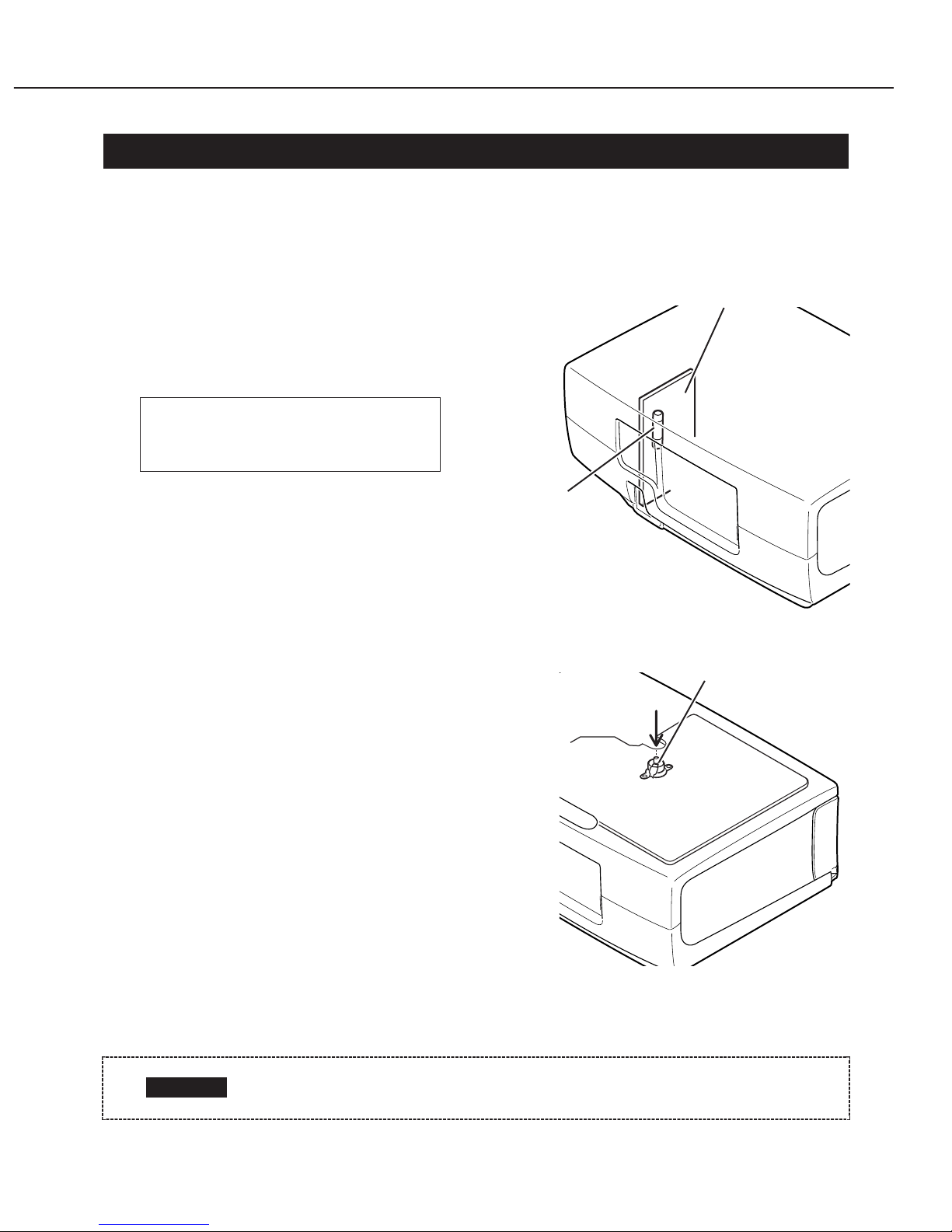
2.1 Fuse
A fuse is located inside of the projector. When
the POWER indicator is not lightning, the fuse
may be opened. Check the fuse as following
steps.
The fuse should be used with the following type;
[How to replace the fuse]
1. Remove the cabinet top following to
“Mechanical Disassemblies”.
2. Remove the cover on the Filter Board.
3. Remove fuse from fuse holder.
To install the fuse, take reversed step in the
above.
2.2 Thermal Switch
There is the thermal switch (SW902) inside of
the projector to prevent the internal temperature
rising abnormally. When the internal
temperature reaches near 100˚C, turn off the AC
main power supply automatically.
The thermal switch is not reset to normal
automatically even if the internal temperature
becomes normal. Reset the thermal switch
following procedure.
Check the resistance between terminals of
thermal switch by using the tester. If it has high
impedance, thermal switch may be in operative.
[How to reset the thermal switch]
1. Remove the cabinet top following to “Mechanical Disassemblies”.
2. Press the reset button on the thermal switch with a sharp-pointed tool.
Fuse Part No. CY2-8736-000
TYPE T4.0AH 250V FUSE
LITTEL FUSE INC. TYPE 215004
Before press the reset button, make sure that the AC cord must be
disconnected from the AC outlet.
CAUTION
Fig. 2-1
Fig. 2-2
Filter Board
Thermal Switch
Fuse
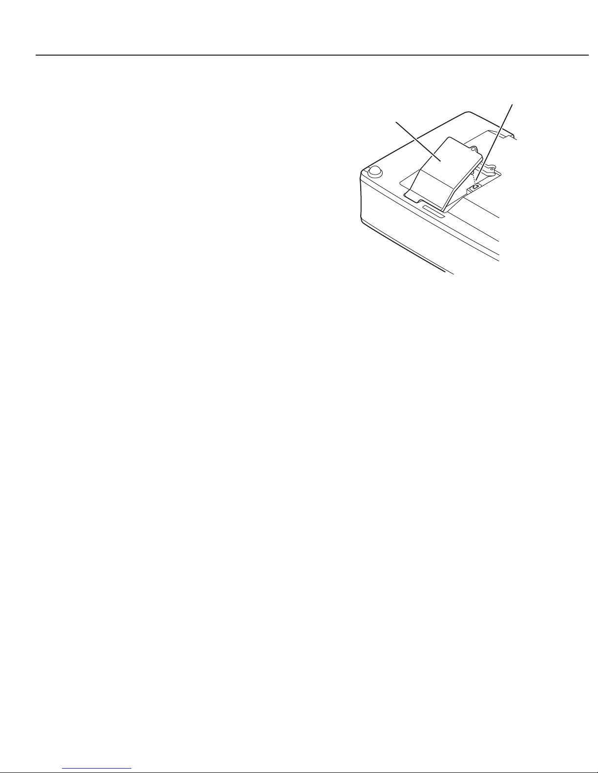
2.3 Lamp Cover Switch
The lamp cover switch (SW8801) cuts off the
drive signal to the lamp circuit when the lamp
cover is removed or no close completely. After
opening the lamp cover for replacing the lamp
ass’y, place the lamp cover correctly otherwise the
projector can not turn on.
2.4 Warning Temperature and Power Failure Protection
The WARNING indicator flashes red and the projector will automatically turn off when
the internal temperature of the projector exceeds the normal temperature or when
stopping cooling fans or when the internal power supply lines are failed.
Check the following possible causes and wait until stopping the WARNING indicator
flashing.
[Possible causes]
• Air filter is clogged with dust particles. Remove dust from the air filter by following
instructions in the “Air filter care and cleaning” below.
• Ventilation slots of the projector are blocked. In such an event, reposition the
projector so that ventilation slots are not obstructed.
• Check if projector is used at higher temperature place (Normal operating temperature
is 5 to 35˚C or 41 to 95˚F)
If the WARNING indicator still continues to flash, there may be defects on cooling fans
or power supply circuits. Please check fan operation and power supply lines referring to
the “Power Supply Lines Chart”.
Part 2: Repair Information
2-3
Fig. 2-3
Lamp Cover Switch
Lamp Cover
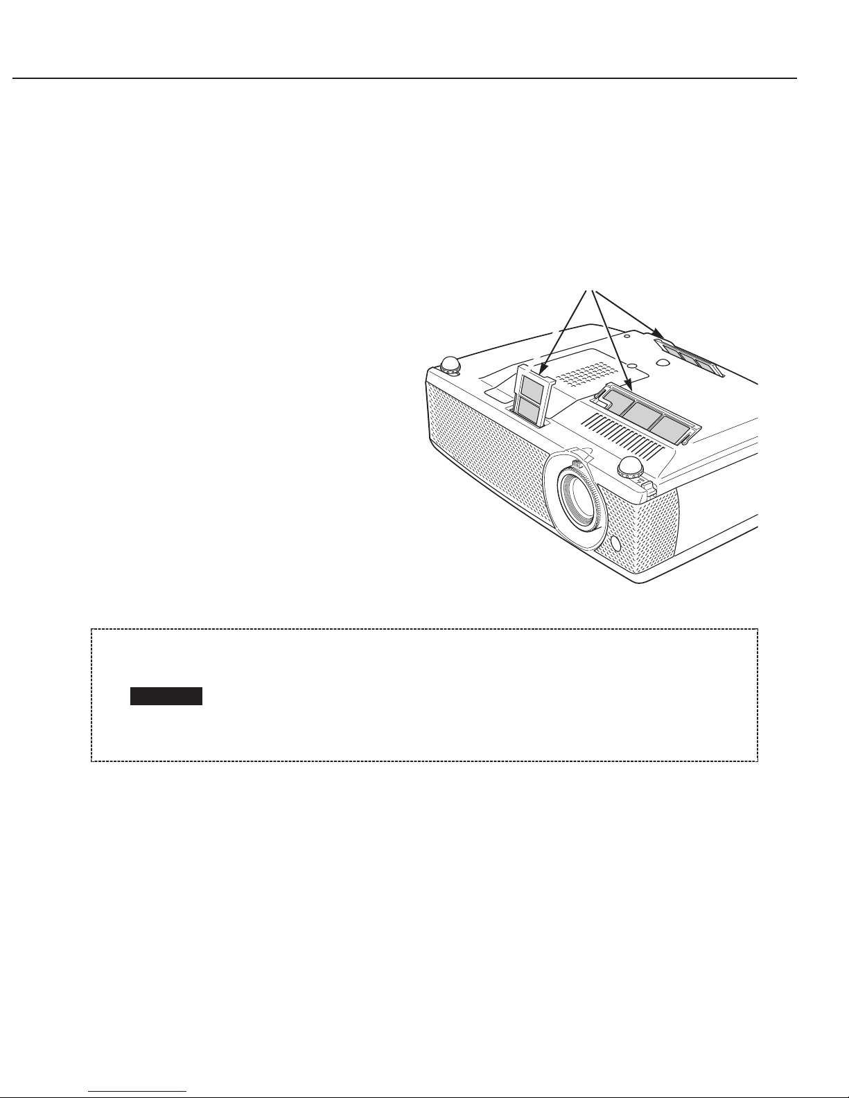
2.5 Air Filter Care and Cleaning
The removable air filter prevents dust from accumulation on the surface of the
projection lens and projection mirror. Should the air filters become clogged with dust
particles, it will reduce the cooling fan’s effectiveness and may result in internal heat
build up and adversely affect the life of the projector.
To clean up the air filters, follow the cleaning procedure below:
1. Turn the projector off, and
disconnect the AC power cord from
the AC outlet.
2. Turn the projector upside down and
remove the air filters by pulling the
latches upward.
3. Clean the air filters with a brush or
wash out dust and particles.
4. Replace each air filter properly.
Make sure that the air filters are
fully inserted.
[RECOMMENDATION]
We recommend avoiding dusty, smoky environments when operating the projector.
Usage in these environments may cause poor image quality.
When using under dusty or smoky conditions, dust may accumulate on optical
elements inside the projector. The condition may degrade the quality of a projected
image.
When the above symptoms are noticed, please clean up the LCD panel and lens
following to the “Cleaning Method”.
Part 2: Repair Information
2-4
Fig. 2-4
Air filters
Do not operate the projector with the air filters removed. Dust may
accumulate on the LCD panel and the mirror, and it may spoil the fine
picture image.
Do not put the small parts into the air intake vents. It may result in the
malfunction of the projector. The air filter is small parts. Take care that
children don’t eat or swallow it.
CAUTION

3. MECHANICAL DISASSEMBLIES
Mechanical disassemble should be made following procedures in numerical order.
Following steps show the basic procedures, therefore unnecessary step may be ignored.
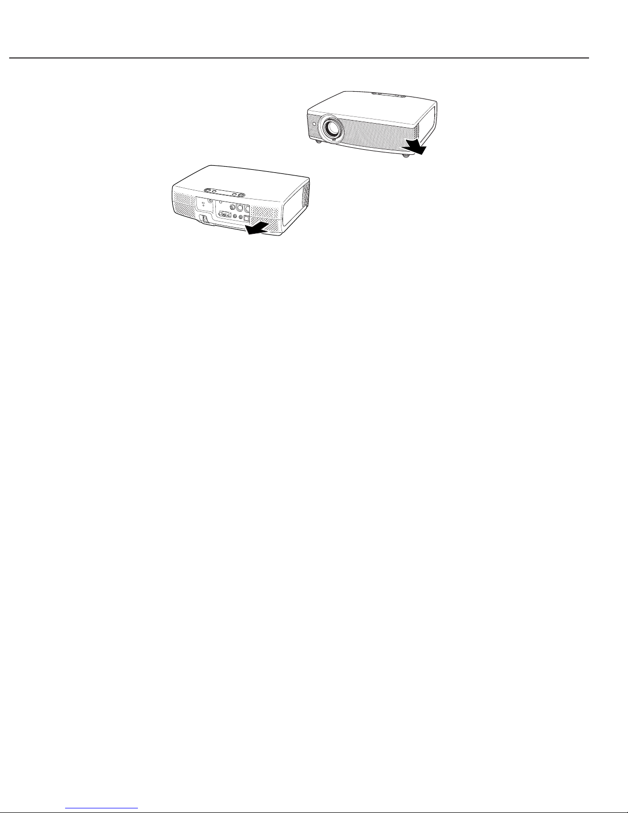
3.1 Side Panel Removal
1. Inset a sharp-pointed tool into the
clearance between the net of the
front cabinet and the side panel,
and slide the side panel toward the
front of the set to take off it.
Note 1: Work with being careful not to
damage the net.
Note 2: Side Panel attachment
Note 2: Put the side panel in the
cabinet with bowing it.
3.2 Cabinet Top Removal
1. Remove 3 screws A (S3x6), screw
A' (S3x5) and 1 screw B (M3x8),
and then take the Cabinet Top
upward off.
Part 2: Repair Information
2-5
The parts and screws should be placed exactly the same position as the
original otherwise it may cause loss of performance and product safety.
Before removing the Cabinets, Remove the Lamp and the Air Filter of the
Cabinet Front part.
CAUTION
Fig. 2-5
Side panel
Screws Expression
(Type Diameter × Length) mm
T type M Type S Type
Fig. 2-6
A
A
B
A
A'
Cabinet Top
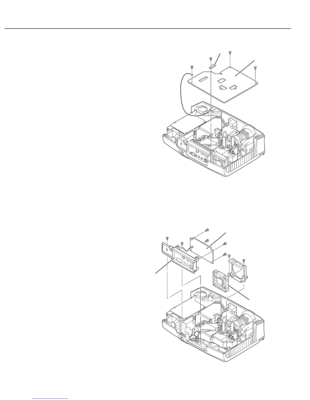
3.3 Main Board Removal
1. Remove 4 screws (M3x6) to take the Main Board
upward.
3.4 Rear Panel, AV Board and FN903 Removal
1. Remove 1 screw A (T3x8) and 1 screw B (M4x4) to take the Rear Panel ass’y off.
2. Remove 2 screws C (T3x8) to take the Fan (FN903) off.
(Do not mistake a fan's installation direction.)
3. Remove 4 screws D (T3x6) and take AV Board off.
Part 2: Repair Information
2-6
Fig. 2-8
Fig. 2-7
Main Board
B
C
D
C
D
D
D
AV Board
Rear Panel
FN903
A
Spacer sheet
 Loading...