

Canon LV-S1U, LV-S1E, D78-5253, D78-5252 Service Manual
SERVICE MANUAL
English Edition
LV-S1U/D78-5252
LV-S1E/D78-5253
By Portable Document Format
1
General
0
PREFACE
2
Repair
3
Adjustment
4
Parts Catalog
5
Electrical Diagrams
Return to Menu
DY8-1785-241 500

CANON Power Projector
LV-S1J D78-5251
CANON Multimedia Projector
LV-S1U D78-5252
LV-S1E D78-5253
SERVICE
SMANUAL

Technical Documents
Application
This CD-ROM is issued by Canon Inc. for qualified persons to learn technical theory and product
repair. This CD-ROM covers all localities where the products are sold. For this reason, there
may be information in this CD-ROM that does not apply to the product sold in your locality.
The following paragraph does not apply to any countries where such provisions are
inconsistent with local law.
Trademarks
The product names and company names described in this CD-ROM are the registered
trademarks of the individual companies.
Copyright
Canon Inc. retains the copyright to all data contained on this CD-ROM.
Reproduction, publication (including on the World Wide Web) alteration, translation into another
language, or other use of the data in whole or part, contained on this CD-ROM without the
written consent of Canon Inc., is prohibited.
PDF Files
This CD-ROM contains PDF files created using Adobe®Acrobat 4.0J. PDF files can be viewed
using Adobe®Acrobat Reader 4.0 or later.
Copyright © 2002 by Canon Inc.
CANON INC.
30-2 Shimomaruko 3-Chome, Ohta-ku,
Tokyo 146-8501, Japan
First published February, 2002

PREFACE
1. Service Manual Composition
This manual contains information on servicing the product. It has the following sections.
Part 1 General Information
Provides the basic information needed to understand the product.
Operating instructions are not included. Refer to the product's instruction book if
necessary.
Part 2 Repair Information
Provides information for disassembly, reassembly, and adjustment of the product, about
the tools required, and their application.
Part 3 Adjustment
Provides information for disassembly, reassembly, and adjustment of the product to
assure precision of the products, about the tools required, and their application.
Part 4 Parts Catalog
Part 5 Electrical Diagrams
2. Model Differences
In this series of products, there are models suffixed "J", "U", and "E". The only
differences between the models are cosmetic, mainly the designation and rating plates.
Internally, they are identical.
The accessories bundled with the product may differ from country to country.
I
Main Marketing Area Japan North America Europe
POWER PROJECTOR
MULTIMEDIA PROJECTOR MULTIMEDIA PROJECTOR
Model Name LV-S1J LV-S1U LV-S1E
3. Tools & Test Equipment
The following tools and equipment are required to perform disassembly, reassembly and
adjustment.
1) Special Tools
None
2) General Purpose Tools (Commercially available, but can be purchased with the
following numbers.)
3) Test Equipment
4) Other Equipment
5) Chart/Software
II
Description Tool No. Specification Remarks
Ball Driver CY9-5002-000 2.0mm Optical Parts Removal
& Adjustment
Hex Key Set CY9-5007-000 2.0mm Optical Parts Removal
& Adjustment
Driver, adjustment CY9-5003-000 1.8mm Electrical Adjustments
Driver, Slot CY9-5004-000 4.0mm Optical Parts
Adjustment
Driver, Cross-point CY9-5005-000 No. 2 Assembly &
Disassembly
Description Tool No. Specification Remarks
Digital Multi-meter Commercially available DC1mmV~500V Electrical Adjustment
Video Signal Generator Commercially available Color Bars and Electrical Adjustment
Gray Scale
Computer Signal Commercially available Gray Scale Electrical Adjustment
Generator (or personal computer)
Oscilloscope Commercially available 100MHz response or Waveform checks and
over Electrical Adjustment
Description Tool No. Specification Remarks
Screen Commercially available Over 40" All Adjustment
Personal Computer Commercially available Windows 95 OS All Adjustment
(with a floppy disk)
Description Tool No. Specification Remarks
Monitor Tester Supplied with manual Bitmap Data All Adjustment
Gray Scale Chart Supplied with manual (XGA and SVGA) All Adjustment
Color Shading Supplied with manual Ver. 1.0.1 Color Shading
Correction Tool Adjustment

CONTENTS
Page
Part 1: General Information
1. FEATURES ...................................................................................................... 1-1
1.1 Development objectives ........................................................................... 1-1
1.2 Major Features ......................................................................................... 1-2
2. SPECIFICATIONS ........................................................................................... 1-4
2.1 Type ......................................................................................................... 1-4
2.2 LCD panel ................................................................................................ 1-4
2.3 Optical box ............................................................................................... 1-4
2.4 Video / Audio ........................................................................................... 1-4
2.5 Connectors .............................................................................................. 1-5
2.6 Standard .................................................................................................. 1-5
2.7 Accessories ............................................................................................. 1-5
2.8 Options .................................................................................................... 1-5
2.9 Others ...................................................................................................... 1-5
3. NOMENCLATURE ........................................................................................... 1-6
3.1 Main Board .............................................................................................. 1-6
3.2 Top controls ............................................................................................. 1-6
3.3 Rear panel terminals ................................................................................ 1-6
3.4 Computer Input terminal / Control port connector .................................... 1-6
3.5 Remote control ........................................................................................ 1-6
3.6 Remote control operating range .............................................................. 1-6
4. COMMENTARY ............................................................................................... 1-7
4.1 External appearance design .................................................................... 1-7
4.2 Optical System ......................................................................................... 1-7
4.3 Video Input System .................................................................................. 1-10
4.4 Image Control .......................................................................................... 1-11
4.5 Other functions ........................................................................................ 1-12
4.6 Mechanism .............................................................................................. 1-12
5. CONNECTION DIAGRAM ............................................................................... 1-14
5.1 Connection to the computer ..................................................................... 1-14
5.2 Connecting to the video equipment ......................................................... 1-14
6. SETTING-UP THE PROJECTOR .................................................................... 1-15
6.1 Positioning the projector .......................................................................... 1-15
6.2 Installation precautions ............................................................................ 1-15
7. SUPPORTED COMPUTER SYSTEM MODE ................................................. 1-16
Part 2: Repair Information
1. SAFETY INSTRUCTIONS ............................................................................... 2-1
2. LAMP REPLACEMENT ................................................................................... 2-2
3. CIRCUIT PROTECTIONS ............................................................................... 2-4
3.1 Fuse ......................................................................................................... 2-4
3.2 Temperature Protection equipment ......................................................... 2-4
4. SERVICE ......................................................................................................... 2-6
4.1 Cabinet Top Removal .............................................................................. 2-6
III

4.2 Front Cabinet Removal ............................................................................ 2-6
4.3 Main Board and Sub-Board Removal ...................................................... 2-7
4.4 Power Supply Unit and Fan (FN903) Removal ........................................ 2-7
4.5 AV Unit and Fan (FN907) Removal ......................................................... 2-8
4.6 Lamp Ballast Unit Removal ..................................................................... 2-8
4.7 Optical Unit, Fan (FN901) and Fan Louver Removal .............................. 2-9
4.8 Air Duct and Fan Removal ....................................................................... 2-9
4.9 Lens and Panel Prism Assembly Removal .............................................. 2-10
5. CLEANING ....................................................................................................... 2-11
Part 3: Adjustment
1. PRECAUTIONS FOR ADJUSTMENT ............................................................. 3-1
1.1 Service Mode ........................................................................................... 3-1
1.2 Adjustments Required after Parts Assembly and Replacement .............. 3-1
1.3 Service Mode Adjustment Items .............................................................. 3-2
1.4 IC Adjustment Data .................................................................................. 3-3
2. ELECTRICAL ADJUSTMENTS ....................................................................... 3-5
2.1 Fan Voltage Adjustment .......................................................................... 3-5
2.2 NRS Adjustment ...................................................................................... 3-5
2.3 Signal Center DC Voltage Adjustment ..................................................... 3-5
2.4 Contrast Adjustment ................................................................................ 3-6
2.5 Signal Level Adjustment .......................................................................... 3-7
2.6 Flicker Adjustment ................................................................................... 3-7
2.7 White Balance Adjustment ....................................................................... 3-8
2.8 Contrast Linearity Adjustment .................................................................. 3-8
2.9 Color Shading Correction ........................................................................ 3-8
3. TEST POINTS LOCATIONS ............................................................................ 3-9
4. TROUBLESHOOTING ..................................................................................... 3-10
Part 4: Parts Catalog
Part 5: Electrical Diagrams
1. PARTS DESCRIPTION AND READING IN SCHEMATIC DIAGRAM ............. 5-1
2. DIODE, TRANSISTOR AND IC PINS .............................................................. 5-3
Schematic Diagrams ........................................................................................ A1
Printed Wiring Board Diagrams ........................................................................ A7
IV

Part 1
General
Information
Part 1: General Information
1-1
1. FEATURES
1.1 Development objectives
The LCD projector market is expected to grow 25% year-on-year in 2001. In
particular, the micro-portable projectors (3 kg or less) are expected to be dominant in
the market and have a share of 59% (27% in 2000). (World Wide: Fuji Kimera Research
Institute, Inc.) However, there are already approx. 20 XGA models in the market and
the competition is sure to become even more cutthroat.
Canon put the LV-7105 (XGA) and LV-5110 (SVGA) in the market in May 2001. It
needs to introduce new competitive products because competition among leading
makers is intensifying and other manufacturers have put many new products in market.
The LV-X1 contains the first Canon-made optical box and uses its own technology for
projection lenses, prisms and optical system components to achieve the top-class
brightness with a compact and low-priced model. Although it is an alliance product, it
incorporates the Canon's ideas in video processing and design, and aims at
outperforming competitors. It is an important model as a milestone for manufacturing
Canon's own projectors.
The LV-S1 is the first SVGA model equipped with the first optical box made by Canon
and has been developed as a model in the Canon's lineup of new-generation projectors.
It has the same performance and mobility as the XGA model, LV-X1, but has a lower
price to improve cost effectiveness and expand the share in the office personal
equipment and SOHO market.
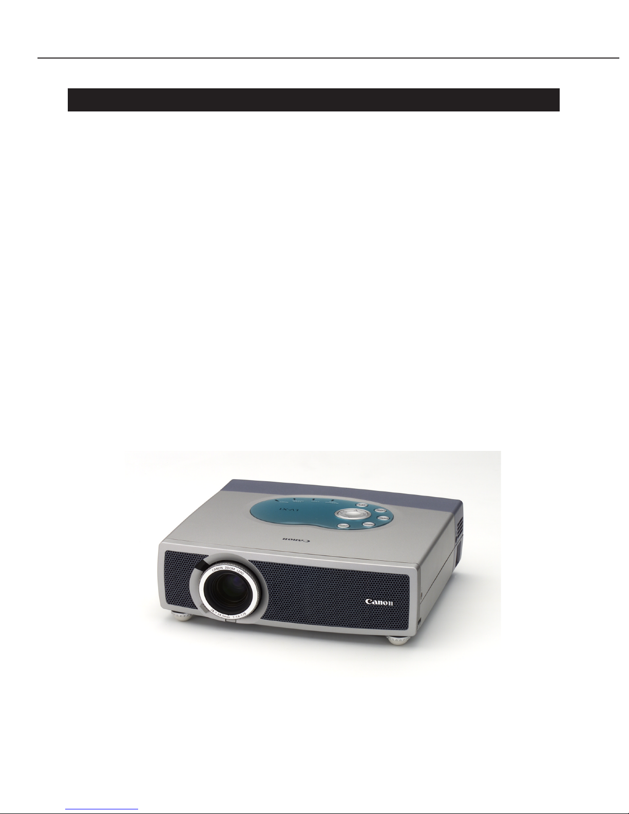
Fig. 1-1 LV-X1, S1 External View

1.2 Major Features
L
V-X1
● Canon's first original optical box
The projector has the first F1.6 zoom projection lens in the industry. The lens has
been designed optimally for the projector with a micro-lens LCD panel. In addition, it
contains a lot of Canon's optical technology, such as newly-developed high-refractivity
4P color synthesis prism, free curved surface mirror, and fluorite field lens, and
provides high-quality video output, though it is compact and has high intensity.
● High intensity 1100 ANSI lumen
The Canon's original optical design achieves 1100 ANSI lumen, which is the highest
brightness in the 0.7-inch class.
● Real XGA projection, high-quality projection by SXGA digital compression
Real XGA projection is implemented using a 0.7" LCD panel with 1024 x 768 pixels.
High-quality SXGA projection can be provided by digital compression technology.
● Video mode selection based on projection data
The optimum intensity levels are provided according to contents by switching the
video mode to Standard/High Contrast for PC input and to Standard/Cinema for
video input.
● 37dB silent design
The automatic fan control system reduces noise.
A thermal sensor is used to lower fan speed to suppress noise when the temperature
is low.
● Component input support and USB interface
In addition to the normal video input (composite input) and S-Video input, component
input from DVD players, etc. is supported.
The projector has a USB connector to support the mouse function.
● Plug & Play ... When it is connected, the projector is recognized automatically and can
be used immediately without adjustment.
• Recognize horizontal and vertical scanning frequencies of a PC automatically.
• Adjust the number of dots in the horizontal direction of the screen, tracking and
screen position automatically.
• Recognize Video, S-Video and component input automatically.
• Support NTSC/PAL/SECAM/NTSC4.43/PAL-M/PAL-N.
● Extended Digital Keystone function, up to +/-20 degrees
Smoothly corrects for "keystone" effect, giving a square image with up to 20 degrees
tilt.
Part 1: General Information
1-2

L
V-S1 (Only different points from the LV-X1 are described below.)
● Canon's first original optical box
The projector has the first F1.6 zoom projection lens in the industry. In addition, it
contains a lot of Canon's outstanding optical components, such as a newly developed
high-refractivity 4P color synthesis prism, a free curved surface mirror and a fluorite
field lens to provide the highest intensity and highest-quality video output in its class.
● High intensity 1000 ANSI lumen
The highly cost effective SVGA model achieves high brightness of 1000 ANSI lumen.
● Real SVGA projection, high-quality projection by XGA digital compression
Real SVGA projection is implemented by using a 0.7" LCD panel with 800 x 600
pixels.
High-quality XGA projection can be provided by digital compression technology.
Part 1: General Information
1-3

Part 1: General Information
1-4
2. SPECIFICATIONS
2.1 Type Micro-portable XGA LCD Projector (LV-X1)
Micro-portable SVGA LCD Projector (LV-S1)
2.2 LCD panel
1. Type : Polysilicon active matrix TFT with microlens
(LV-X1: with microlens)
2. Size/number: 0.7 model (4:3 aspect ratio) × 3
3. Number of pixels: 1024 × 768 pixels (XGA LV-X1)
800 × 600 (SVGA LV-S1)
4. Contrast ratio: 300:1 (LV-X1)
350:1 (LV-S1)
2.3 Optical box
1. Type : Dichroic mirror 4P prism system
2. Light source: 150W UHP lamp
3. Projection lens configuration: 11 groups, 12 lenses
4. F value/focal length: F1.6 to 1.78/f28.7 to 34.5mm
5. Zoom magnification: ×1.2
6. Zoom/focus: Manual
7. Lens shift: 19:1
2.4 Video / Audio
1. Brightness: 1100 ANSI lumen, illuminance ratio 85% (LV-X1)
1000 ANSI lumen, illuminance ratio 90% (LV-S1)
2. Correct projection distance: 1.6 to 8.1 m
3. Size of projection image: 34" to 200"
4. Resolution of display supported: SXGA (compression)/XGA/SVGA/VGA (LV-X1)
XGA (compression)/SVGA/VGA (LV-S1)
5. Digital zoom magnification: ×1/2to ×16
6. Horizontal resolution (Video input): 550 TV lines (LV-X1)
500 TV lines (LV-S1)
7. Scanning frequency: 15KHz to 100KHz for horizontal sync.
50Hz to 100Hz for vertical sync.
Up to 140MHz for dot clock (LV-X1)
15KHz to 80KHz for horizontal sync.
50Hz to 100Hz for vertical sync.
Up to 100MHz for dot clock (LV-S1)
8. Built-in speaker: 2cm × 3.5cm
9. Audio output: 1W monaural

2.5 Connectors
1. Computer input: Video: D-sub 15-pin/audio: mini (stereo) jack
2. Video input: Video: RCA × 3, S-Video/audio: mini (stereo) jack
(Use three RCA terminals for component input and 1
terminal for composite input.)
3. Audio output: Stereo mini jack
4. Mouse control: Mini DIN 8 pins, USB type (type B)
2.6 Standard
1. Dimensions (W x H x D): 260mm × 76mm × 230mm (See the External View.)
2. Net Weight: 2.85Kg (Nominal weight: 2.8Kg)
3. Rated supply voltage: 100V/100 to 120V/200 to 240V, 50/60Hz
4. Power consumption: 250W
5. Noise: 37dB
6. Operating temperature: 5 to 35˚C
7. Storage temperature: –10 to 60˚C
2.7 Accessories
1. Wireless remote control transmitter
2. Computer connection cable (Dsub15-Dsub15)
3. Lens cap
4. Soft carrying case
5. Power cord
2.8 Options
1. Wireless remote control with mouse control function (LV-RC01)
The remote control has a mouse control function to operate the pointer on the PC.
It also has a laser pointer function.
2. Canon ceiling mount fitting LV-CL06
Hanger for ceiling mount
* Ask a specialist to install the projector in the best location.
2.9 Others
Canon replacement lamp (LV-LP12)
Recommended lamp replacement time 1000 hours
Part 1: General Information
1-5

3. NOMENCLATURE
3.1 Main Board: See the attached sheet
(Owner's Manual, page 7).
3.2 Top controls: See the attached sheet
(Owner's Manual, page 16).
3.3 Rear panel terminals: See the attached sheet
(Owner's Manual, page 11).
3.4 Computer Input terminal / Control port connector:
See the attached sheet
(Owner's Manual, page 42).
3.5 Remote control: See the attached sheet
(Owner's Manual, page 14).
3.6 Remote control operating range: See the attached sheet
(Owner's Manual, page 15).
Part 1: General Information
1-6

Part 1: General Information
1-7
4. COMMENTARY
4.1 External appearance design (The LV-X1 is different from the LV-S1
only in product logos.)
● External Styling
The entire body has a refined and lively three-dimensional form that suits a video
equipment to make it less conspicuous and give a sophisticated and friendly
impression in the environment where it is installed. Although it provides high
brightness and high quality, it is designed to save space to reduce restrictions on the
installation place. It can be used in various places from bright offices with external
light to home theaters.
● Details
The exhaust port from which heat and noise are produced is laid out on the front
panel that is far from the operator. The port is equipped with a cover to give an
impression of stylish precision.
The rear design is simplified so that the user can concentrate on the projected image.
The operation panel is finished so that the focus ring and zoom lever show the
Canon's brand image. The operation panel on the top is tilted to the rear to improve
operability and buttons are laid out around the cursor keys so that they can be
operated by touching with a hand without looking at them.
● Coloring
This projectors has two basic colors of satin metallic silver and glacial blue and has a
clear water blue area as an accent to give an impression of high quality and lightness.
It is finished so that it matches offices (conference), shops (promotion) and homes (AV
system). Stain and weatherability have been considered so that it can be used for a
long time. Its worth can be discerned when it is used for an extended period of time.
● Ecology
The number of parts is reduced, and polyvinyl chloride and lead are not used as
materials. Materials are shown on all external parts.
All the screws have the same size so that they can be removed with a single
screwdriver.
4.2 Optical System
LV-X1
A newly-developed high-refractivity 4P color synthesis prism is adopted to minimize
deterioration of picture quality due to the color synthesis prism. In addition, a large
aperture F1.6 zoom lens suitable for the LCD panel with a microlens is used to achieve
the highest brightness of 1100 ANSI lumen in the 0.7-inch class.
Cooling efficiency is improved greatly by using fluorite with high thermal conductivity
as two field lenses to escape the heat of the deflector.
A free curved surface mirror is used in the illumination relay optical system to reduce
weight, and a teletype illumination optical system is used to reduce the size markedly.

Part 1: General Information
1-8
● High-refractivity 4P color synthesis prism
The lines at the center of the screen and bad images, which are problems with the
conventional cross-dichroic prism, are eliminated by using a configuration in which
the dichroic membrane is not crossed in the prism. Since the panel and B panel are
not faced with each other, light does not leak to other channels, and color shading can
be suppressed to ensure high-quality video output.
By using a high-refractivity glass, the back focus can be suppressed during air
conversion of the projection lens, so a small lens can be designed. By dividing the
prism between dichroic membranes into two parts, shading of the effective light flux
on the exit side is suppressed and the prism is made compact.
● Large aperture zoom lens: F1.6
A large aperture F1.6 projection lens suitable for the LCD panel with a microlens has
been optimally designed. The zoom has been designed so that four of six groups are
moved to minimize aberrations and achieve the highest brightness in its class, 1100
ANSI lumen. (The optical system has 11 groups of 12 elements.)
● Fluorite field lens
The fluorite with a high heat conductivity is used as a material of the field lens located
adjacent to the LCD panel. A deflector is attached to the flat part of the fluorite field
lens. This reduces thermal load on the deflector and reduces the number of parts.
As the LCD projectors are getting smaller and brighter recently, the heat in the
projector is becoming a problem. Especially, there is a problem that the deflector is
deteriorated by heat in a short time.
A general measure is to attach a deflector to a flat plate of sapphire with a heat
conductivity approx. 40 times as high as glass to dissipate heat, but using sapphire
costs high.
This product uses a convex fluorite with a thermal conductivity approx. 10 times as
high as glass and 6 times as thick as the sapphire plate to provide heat dissipation
equivalent to or higher than that of sapphire and high cost-effectiveness.
● Free curved surface mirror
A free curved surface mirror is used in the red light path optical system whose optical
path length is different from that of other channels.
The Canon's free curved surface design technique reduces the number of parts and
reduces weight drastically compared with the conventional relay optical systems.
The three-panel LCD projectors with three LCD panels decomposes light from the light
source into three color components R, G, and B, and passes them through separate
LCD panels. One of the three light paths from the light source to the LCD panels is
longer than the other two, and the relay optical system consists of three lenses and
two mirrors.
This product consists of two parts: "free curved surface mirror with two integrated
sides" and "concave mirror".
● Teletype illumination optical system
The teletype illumination optical system in which a concave lens and a convex lens
are laid out from the light source lamp is used to reduce the overall length of the
illumination optical system.

L
V-S1 (Only different points from the LV-X1 are described below.)
A newly developed high-refractivity 4P color synthesis prism is adopted to minimize
deterioration of picture quality due to the color synthesis prism. A short arc lamp, a
large aperture LCD panel, an illumination optical system and a F1.6 zoom lens suitable
for the LCD panel are used for optimum design to achieve the highest brightness of
1000 ANSI lumen in the 0.7-inch class.
The basic structure of the optical box is almost the same as that of the LV-X1, but the
parts, other than the projection lens and prism unit, are designed optimally to suit the
SVGA LCD panel.
The LV-X1 has a structure called a teletype illumination optical system, in which a
convex lens and a concave lens are arranged in this order to suit the LCD panel with a
microlens. On the other hand, the LV-S1 model has a dedicated structure in which
there is a convex lens, but no concave lens.
● Large aperture zoom lens: F1.6 (The structure is the same as that of the LV-X1.)
A large aperture F1.6 projection lens suitable for the bright illumination system for
SVGA has been adopted. The optical system has 11 groups of 12 elements. The zoom
has been designed so that four of six groups are moved to minimize aberrations
caused by a large aperture lens.
It is combined with an illumination optical system that supports the SVGA panel to
achieve the top-level brightness of 1000 ANSI lumen in the 0.7" SVGA class.
● LCD panel
Since the aperture ratio of the SVGA LCD panel is larger than that of the XGA, thus
eliminating the need to use a microlens. The contrast ratio (entirely blank/black) is
350:1.
Part 1: General Information
1-9
Part 1: General Information
1-10
4.3 Video Input System
1) Video modes
In addition to the standard gradation reproduction mode, some reproduction modes
are available according to circumstances for each input medium.
A custom mode is provided so that the user can fine-adjust reproducibility.
● Standard
Normal setting for general images for both PC and video.
* The standard for the PC is different from that for the video.
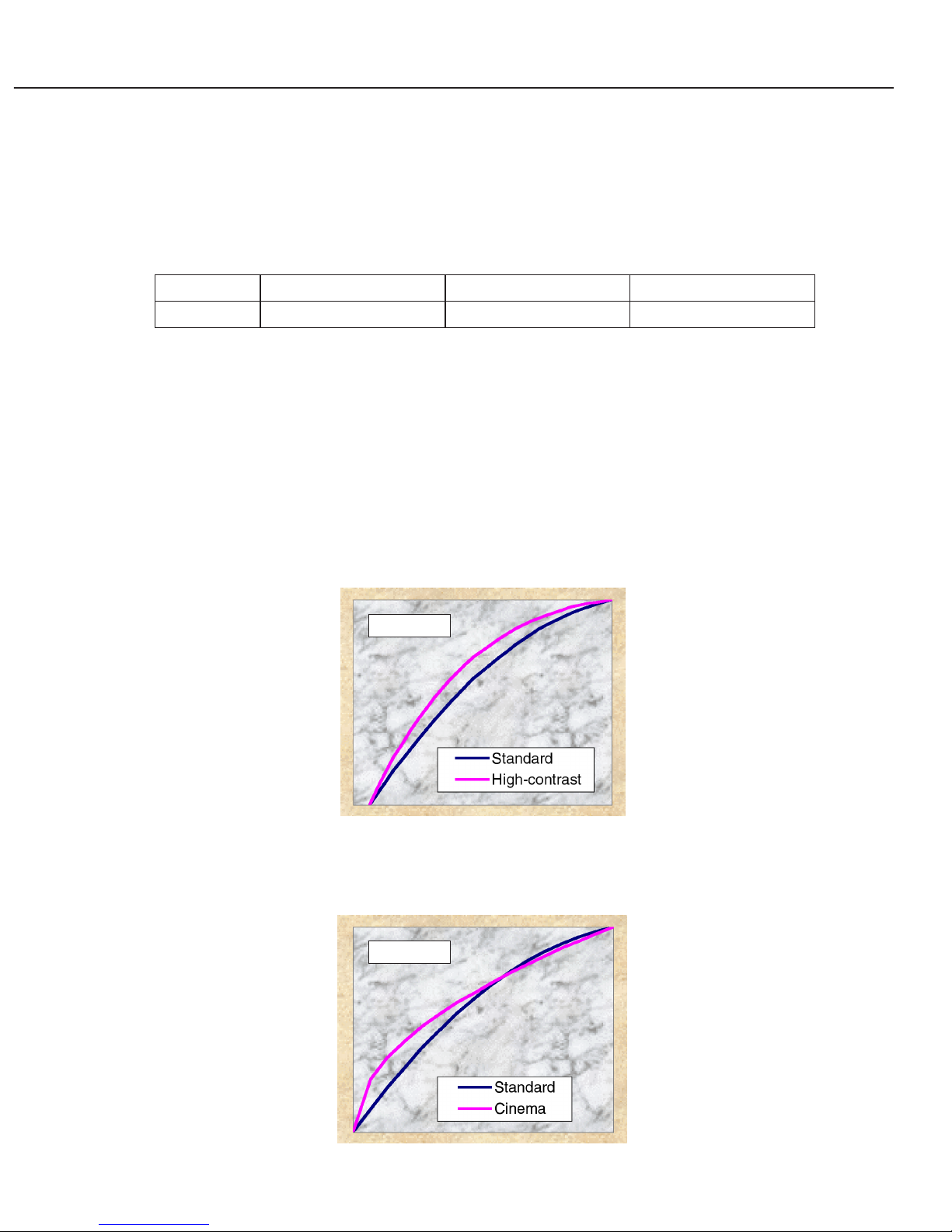
● PC input high contrast
Compared with the standard, the entire screen is made bright by reproducing middleintensity areas more brightly.
In standard mode, low-intensity areas darken in a bright illuminated environment.
The gradations of low-intensity areas, which darken in standard mode, can be
reproduced properly in high contest mode in which the characteristics curve is
sharpened in a range from low-intensity to middle-intensity.
● Cinema mode for video input
The low-intensity area is raised with respect to standard setting to improve
reproducibility in this area. It is effective to improve reproduction of dark images.
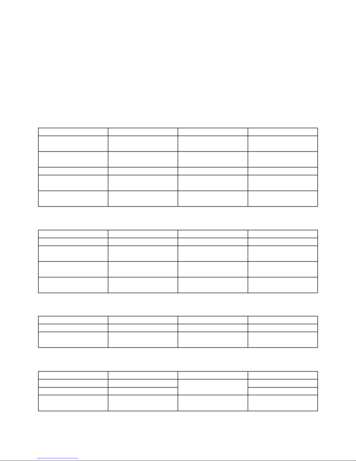
Video input
PC input
PC input Standard mode High contrast mode Custom
Video input Standard mode Cinema mode
Custom

● Custom mode
In addition, the gamma characteristics curve can be adjusted with +/-8 gradations in
any of the above modes.
2) Support various input devices
● Real XGA mode, compressed SXGA mode
Real XGA images can be projected with the 0.7" LCD panel with 1024 x 768 pixels.
High-quality SXGA images can also be projected using the digital compression
technology.
SXGA, XGA, SVGA and VGA models are supported.
● Multi scanning system AMSS (Automatic Multi Scanning System)
The AMSS recognizes the horizontal and vertical scanning frequencies of a PC
automatically.
● Supports HDTV, DTV and DVD component input.
Supports color difference signals (Y, Pb/Cb, Pr/Cr) input. Clear images are
reproduced with minimal blurring of color.
* The composite (video) input uses the same connector as used for the intensity signal
(Y) for component input.
● Color system
Supports many color systems: NTSC, PAL, SECAM, NTSC4.43, PAL-M and PAL-N.
The projector detects color system automatically in automatic mode (except PAL-M
and PAL-N).
● Automatic image function (total number of dots, fine sync, position)
The number of dots in the horizontal direction of the screen, tracking, and screen
position can be automatically adjusted.
The items with the automatic adjustment enabled can be adjusted by pushing the
[AUTO IMAGE] button on the remote control.
4.4 Image Control
● Keystone adjustment function (+/-20 degrees)
Smoothly corrects for "keystone" effect on the projection screen, giving a square image
with up to 20 degrees tilt.
● Digital zoom function (x1/2- x16)
Digital zoom enlarges a selected part of the screen.
● Image inversion function (Left / Right, Up / Down)
Images can be inverted horizontally on rear projection and can be inverted
horizontally and vertically when the projector is suspended from the ceiling.
Part 1: General Information
1-11

● Video freeze function
When the [FREEZE] button on the remote control is pressed, the displayed image is
frozen.
The output from an output device, such as a personal computer, is not reflected on
the screen.
● Non-display function
The image is blanked when the [NO SHOW] button on the remote control is pressed.
4.5 Other functions
● Graphical user interface
Pressing the [MENU] button displays a menu bar on the screen.
Functions are displayed easily by icons on the menu bar.
* Multi-language OSD (English, German, French, Italian, Spanish, Portuguese, Dutch,
Swedish, Chinese, Korean and Japanese)
Language used in ON-SCREEN MENU is selectable from among 11 languages. The
projector can be used world-wide.
● Presentation timer
When the [P-TIMER] menu on the remote control is pressed, the counting of elapsed
time begins and it is displayed at a corner of the screen.
Whenever the button is pressed, it is started (display), stopped and reset (no display).
4.6 Mechanism
● Elevation mechanism
The height and tilt of the projection screen can be adjusted with adjustable feet on the
front bottom of the body.
The front of the projector can be lifted a maximum of 10.7 degrees.
● Automatic fan control system
When the thermal sensor detects a low temperature, fan speed is reduced
automatically to suppress fan noise, thus achieving 37dB.
The thermal sensor is located near the air inlet to measure temperature accurately
and control fan speed.
The fan components have been modified as the size has been reduced.
● Internal speaker
A monaural 1W speaker is built in to play sounds from a PC or video.
* Sound muting ... Sound can be turned on or off with the [MUTE] button on the
remote control.
● Power management function
This function turns Projection Lamp off when this projector detects signal
interruption for a certain period, and turns it on when a signal comes in.
Part 1: General Information
1-12

● Easy lamp replacement mechanism
The user can replace the lamp easily.
Canon replacement lamp LV-LP12
● User cleaning air filter mechanism
The user can remove and clean the air filter easily.
● World-wide voltage specification
The power supply mechanism supports 90V to 264V.
Part 1: General Information
1-13

Part 1: General Information
1-14
5. CONNECTION DIAGRAM
5.1 Connection to the computer: See the attached sheet
(Owner's Manual, page 12).
5.2 Connecting to the video equipment: See the attached sheet
(Owner's Manual, page 13).
 Loading...