

Canon imageRunner Advance C5051 Series, imageRunner Advance C5045 Series, imageRunner Advance C5035 Series, imageRunner Advance C5030 Series Service Manual
September 24, 2009
fin
Product Outline
Function
Periodic Servicing
Parts Replacing and Cleaning
Adjustments
Troubleshooting
Error Code
Service Mode
Installation
Appendix
Revision 0
imageRUNNER ADVANCE
Service Manual
C5051/C5045/C5035/C5030 Series
987654321

Application
fin
This manual has been issued by Canon Inc. for qualied persons to learn technical theory,
installation, maintenance, and repair of products. This manual covers all localities where the
products are sold. For this reason, there may be information in this manual that does not
apply to your locality.
Corrections
This manual may contain technical inaccuracies or typographical errors due to improvements
or changes in products. When changes occur in applicable products or in the contents of this
manual, Canon will release technical information as the need arises. In the event of major
changes in the contents of this manual over a long or short period, Canon will issue a new
edition of this manual.
0-2
The following paragraph does not apply to any countries where such provisions are
inconsistent with local law.
Trademarks
The product names and company names used in this manual are the registered trademarks
of the individual companies.
Copyright
This manual is copyrighted with all rights reserved. Under the copyright laws, this manual may
not be copied, reproduced or translated into another language, in whole or in part, without the
written consent of Canon Inc.
(C) CANON INC. 2009
Caution
Use of this manual should be strictly supervised to avoid disclosure of condential
information.
0-2
0-3
fin
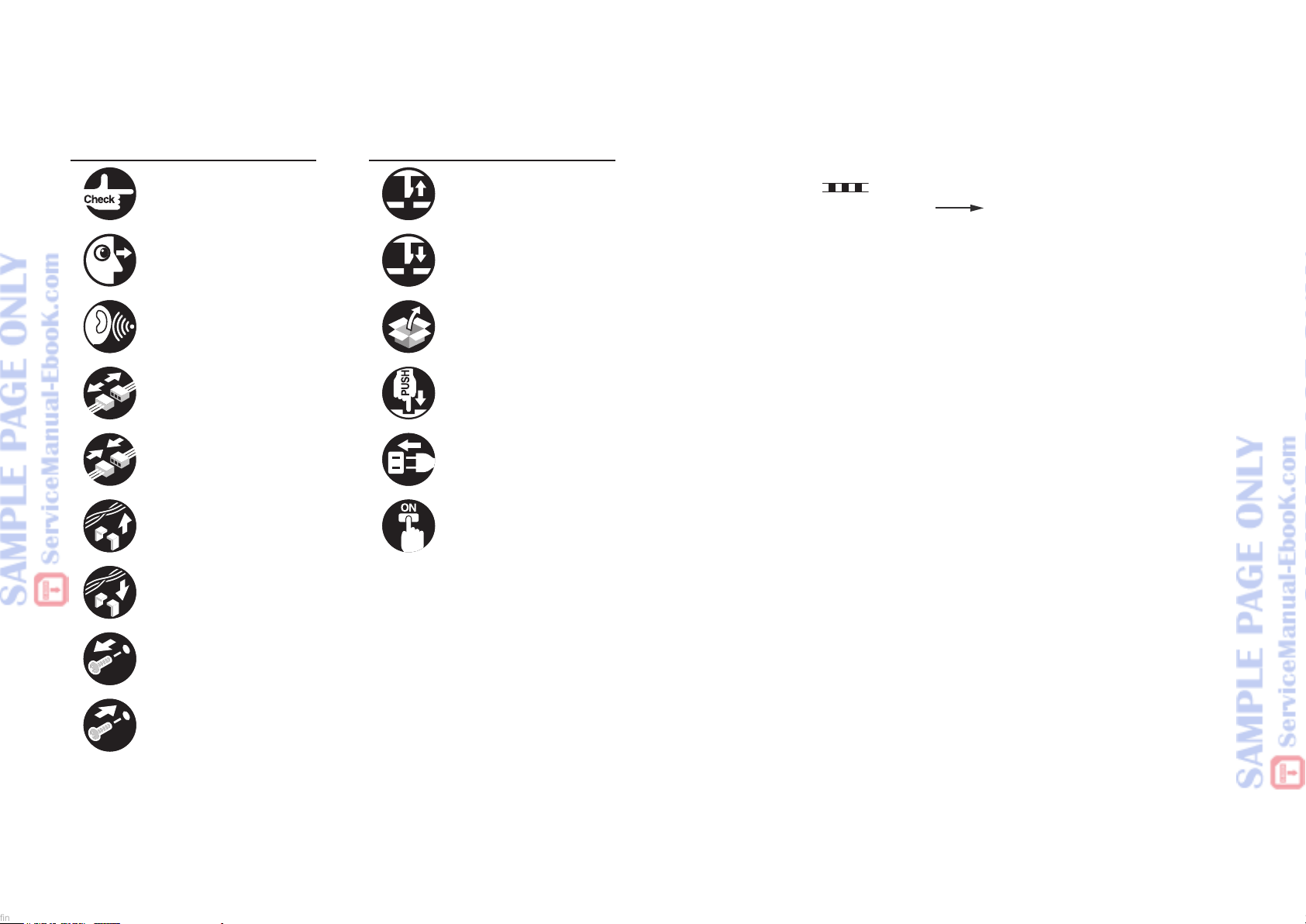
Explanation of Symbols
The following symbols are used throughout this Service Manual.
Symbols Explanation Symbols Explanation
Check.
F-0-1F-0-1
Check visually. Insert the claw.
F-0-3F-0-3 -0-4-0-4
Check the noise. Use the bundled part.
F 0-5F 0-5 -0-6-0-6
Disconnect the connector.
F 0-7F 0-7 0-80-8
Connect the connector. Plug the power cable.
0-90-9 F 0-10F 0-10
Remove the cable/wire
from the cable guide or wire
saddle.
0-110-11 F-0-12F-0-12
Set the cable/wire to the
cable guide or wire saddle.
0-130-13
Remove the screw.
Remove the claw.
F-0-2F-0-2
Push the part.
Turn on the power.
The following rules apply throughout this Service Manual:
1. Each chapter contains sections explaining the purpose of specic functions and the
relationship between electrical and mechanical systems with reference to the timing of
operation.
In the diagrams,
accompanies the symbol, the arrow
represents the path of mechanical drive; where a signal name
indicates the direction of the electric
signal.
The expression "turn on the power" means ipping on the power switch, closing the
front door, and closing the delivery unit door, which results in supplying the machine with
power.
2. In the digital circuits, '1' is used to indicate that the voltage level of a given signal is
"High", while '0' is used to indicate "Low". (The voltage value, however, differs from
circuit to circuit.) In addition, the asterisk (*) as in "DRMD*" indicates that the DRMD
signal goes on when '0'.
In practically all cases, the internal mechanisms of a microprocessor cannot be checked
in the eld. Therefore, the operations of the microprocessors used in the machines
are not discussed: they are explained in terms of from sensors to the input of the DC
controller PCB and from the output of the DC controller PCB to the loads.
The descriptions in this Service Manual are subject to change without notice for product
improvement or other purposes, and major changes will be communicated in the form of
Service Information bulletins.
All service persons are expected to have a good understanding of the contents of this Service
Manual and all relevant Service Information bulletins and be able to identify and isolate faults
in the machine.
0-140-14
Tighten the screw.
F-0-15F-0-15
0-3
Safety Precautions
fin
CDRH Act
■
Laser Safety
■
Handling of Laser System
■
Turn power switch ON
■
Safety of Toner
■
Notes When Handling a
■
Lithium Battery
Notes Before Servicing
■
imageRUNNER ADVANCE
C5051/5045/5035/5030
Series
CANON INC.
MANUFACTURED:
30-2,SHIMOMARUKO,3-CHOME,OHTA-KU,TOKYO,JAPAN
THIS PRODUCT CONHORMS WITH DHHS RADIATION
PERFORMANCE STANDARD 21CFR CHAPTER 1
SUBCHAPTER J.
fin
0-2
CDRH Act
The Center for Devices and Radiological Health of the US Food and Drum Administration put
into force regulations concerning laser products on August 2, 1976. These regulations apply
to laser products manufactured on and after August 1, 1976, and the sale of laser products
not certied under the regulations is banned within the Untied States. The label shown here
indicates compliance with the CDRH regulations, and its attachment is required on all laser
products that are soled in the United States.
F-0-16F-0-16
A different description may be used for a different product.
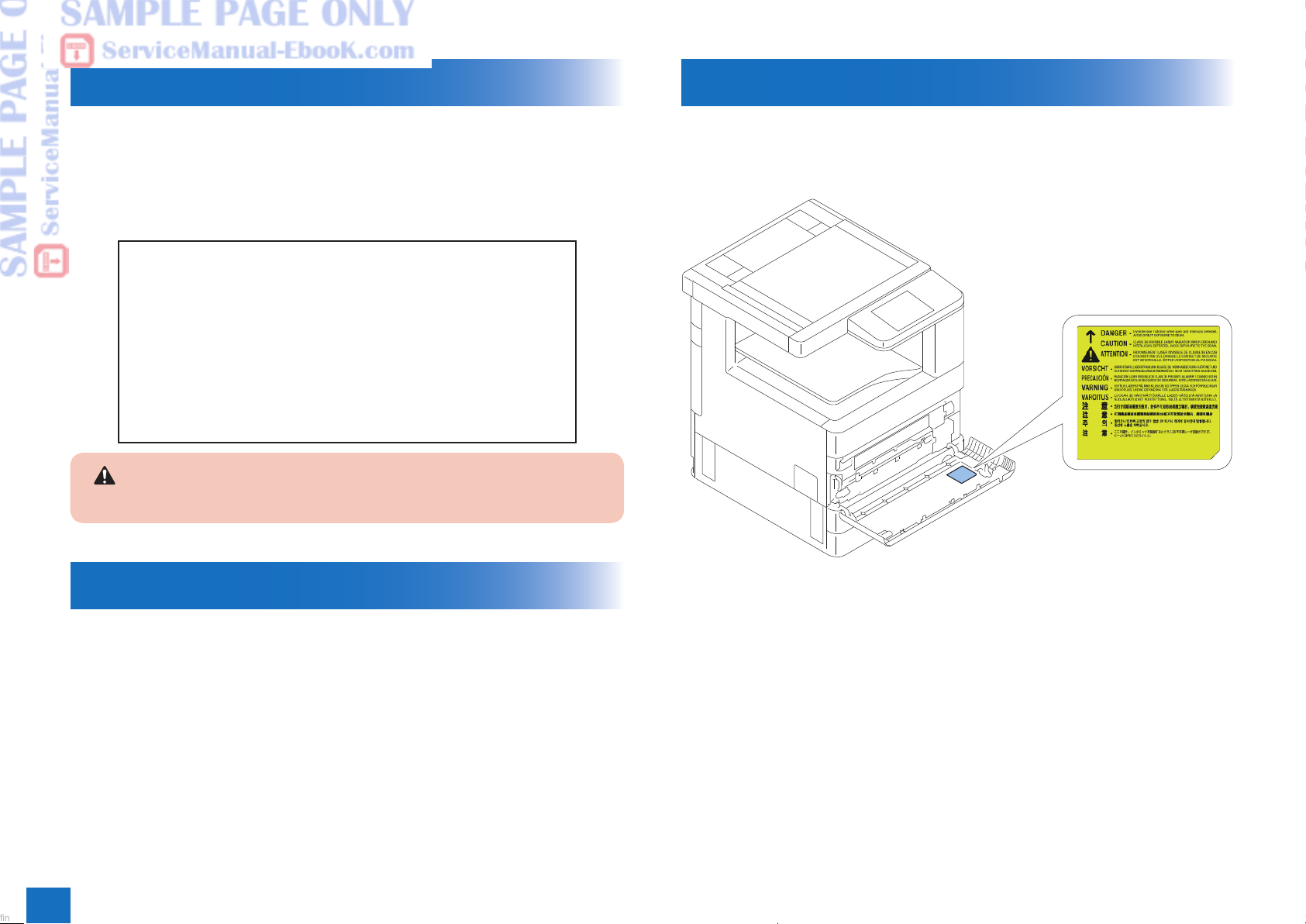
Handling of Laser System
When servicing the area around the laser assembly, be sure to turn off the main power.
The machine's covers that can reect laser light are identied by means of a warning label
(Figure). If you must detach a cover showing the label, be sure to take extra caution during
the work.
Laser Safety
Laser beam radiation may pose a danger to the human body. A laser scanner mounted on the
machine is sealed with the protection housing and external cover to prevent the laser beam
from leaking to the outside. The laser beam never leaks out of the scanner as far as users
operate the machine normally.
0
F-0-17F-0-17
0-2

Product Overview
fin
1
Product Lineup
■
Feature
■
Specications
■
Name of Parts
■
1

Technology
fineline6
2
Basic Conguration
■
Controller System
■
Laser Exposure System
■
Image Formation System
■
Fixing System
■
Pickup Feed System
■
MEAP
■
Embedded RDS
■
2
 Loading...