

Canon imageRUNNER ADVANCE 8500 series, imageRUNNER ADVANCE 6500 series Troubleshooting Manual

Troubleshooting Guide
imageRUNNER ADVANCE
8500/6500 Series
April, 2018
OIP Field Quality Assurance Div.

New Arrival Information
[Regarding Troubleshooting Guide]
Please be advised of the release of Troubleshooting Guide for image RUNNER ADVANCE 8500/6500 Series.
Troubleshooting Guide is a booklet compiled from FAQs issued by Canon Inc.
[Additional case(s)]
• Stained image (at regular intervals of 63mm) due to scratches on the developing upper/lower cylinder
Trouble Shooting Guide will be issued in the future when we have a new issue/FAQ.

Contents
Image Faults......................................................................................................... 1
Black Line appearing in sub scanning direction on image due to fluff adhered to the leaser
exposure path..................................................................................................................................1
Measure against soiled image or blank image due to a fault in the surface finishing of the
developing assembly lower sleeve.................................................................................................. 3
Poor density or white band image due to the boss breakage of the stirring rod................................. 4
Foggy image/black lines due to detached dustproof glass inside the laser scanner unit..................11
Stained image (at regular intervals of 63mm) due to scratches on the developing upper/lower
cylinder.......................................................................................................................................... 12
Faulty Feeding....................................................................................................13
Inconsistent folding position when using booklet mode with a small number of sheets due to
deflected paper inside the processing tray (Booklet Finisher-V1/V2/Y1/AA1)...............................13
Malfunction......................................................................................................... 19
When using the manual stapler, staple position is shifted and sheets are not stapled due to a
spring coming off. (Staple Finisher-V1, Booklet Finisher-V1)........................................................ 19
Message is wrongly displayed due to the displaced waste staple case (Staple Finisher-X1 /
Booklet Finisher-X1 / Staple Finisher-N1 / Booklet Finisher-N1)...................................................24
Response of static touch panel is slow due to electrical noise..........................................................29
" Remove all the output paper" is displayed when delivering to the escape tray (Staple
Finisher-V1/Booklet Finisher-V2)...................................................................................................30
Boss breakage in the shutter of patch sensor assembly occurring when opening/closing the
shutter............................................................................................................................................32
Not all the icons are displayed on the UI screen of main body due to disconnection of the
connectors..................................................................................................................................... 34
Measures when DADF does not open.............................................................................................. 36
Transmission/Fax-Related................................................................................ 39
Skip Blank Originals fails in Scan and Send/Scan and Store due to foreign particles attached
to the scanning area...................................................................................................................... 39
Jam (Main Unit).................................................................................................. 41
0108/0215 jam codes due to the coming off of the detection flag of the photo sensor assembly.....41
Measures when the display of jam 0118/010F/0218/020F/0A18/0A0F cannot be canceled
(POD Deck Lite-C1/Paper Deck Unit-E1/F1).................................................................................42
Jam (Delivery options).......................................................................................44
1004 Jam Code or folded corner on printed out paper due to positional displacement of
support (Staple/Saddle/Booklet/Finisher)...................................................................................... 44
110F Jam code due to meshing failure of the timing belt (Staple-Q1/W1/Booklet-Q1/W1/
Saddle-AK2/Finisher-AK1).............................................................................................................46
i

1002 Jam code due to broken spring of the escape inlet flapper......................................................50
1008 Jam Code due to nip failure of post card feeding rollers (Finisher) .........................................53
Error Code.......................................................................................................... 58
E808-0007 Caused by the fixing drawer cable breakage..................................................................58
E583-800x due to malfunction of the front/rear tray auxiliary guide or coming off of the bearing
of lower stack delivery roller (Staple Finisher-V1 / Booklet Finisher-V1)....................................... 60
E202-0001 and abnormal noise from the reader assembly during the operation due to the
detached flat cable unit..................................................................................................................68
E840-0001 due to the defect securing screws for the fixing shutter motor....................................... 71
E583-8001/E583-8002 due to malfunction of the front/rear tray auxiliary guides(Staple/
Booklet Finisher_V1)..................................................................................................................... 73
E004-0205/E197-0008/E263-0000/E808-000x/E840-0001 caused by damaged coating of the
fixing drawer cable.........................................................................................................................76
E197-0002 due to the worn coating of paper pick-up assembly cable..............................................78
Measure against E674-0100............................................................................................................. 79
E568-8002/Shaved gear tooth due to overloading with friction from sliding while the
estrangement rack is moving (Staple-Q1/W1/Booklet-Q1/W1/Saddle-AM2/AN2/Finisher-
AM1/AN1)...................................................................................................................................... 80
E840-0001 due to rotation failure of a drive shaft in the upper fixing ass'y.......................................84
E017-0002/0003 due to interference of a harness and a sensor flag............................................... 85
Notice of proactive measure against E068-0001.............................................................................. 87
Specifications-Related.......................................................................................88
Regarding the replacing operation of photo-interrupter (shift tray - D1/E1/F1)................................. 88
The breakage of copy tray hooks due to an overloading of output paper (Copy Tray-Q1/R1/R2 )... 90
ii
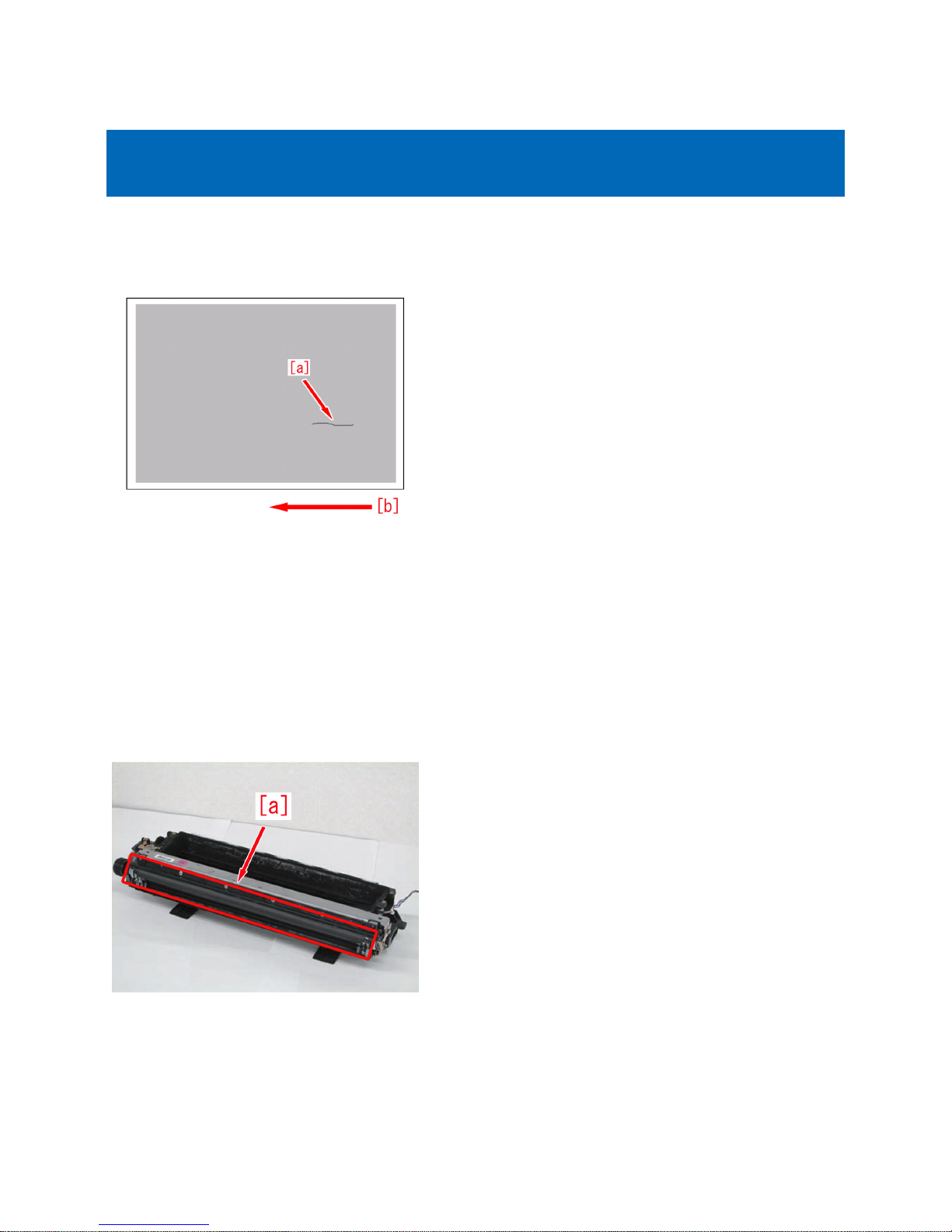
Image Faults
Black Line appearing in sub scanning direction on image due to
fluff adhered to the leaser exposure path.
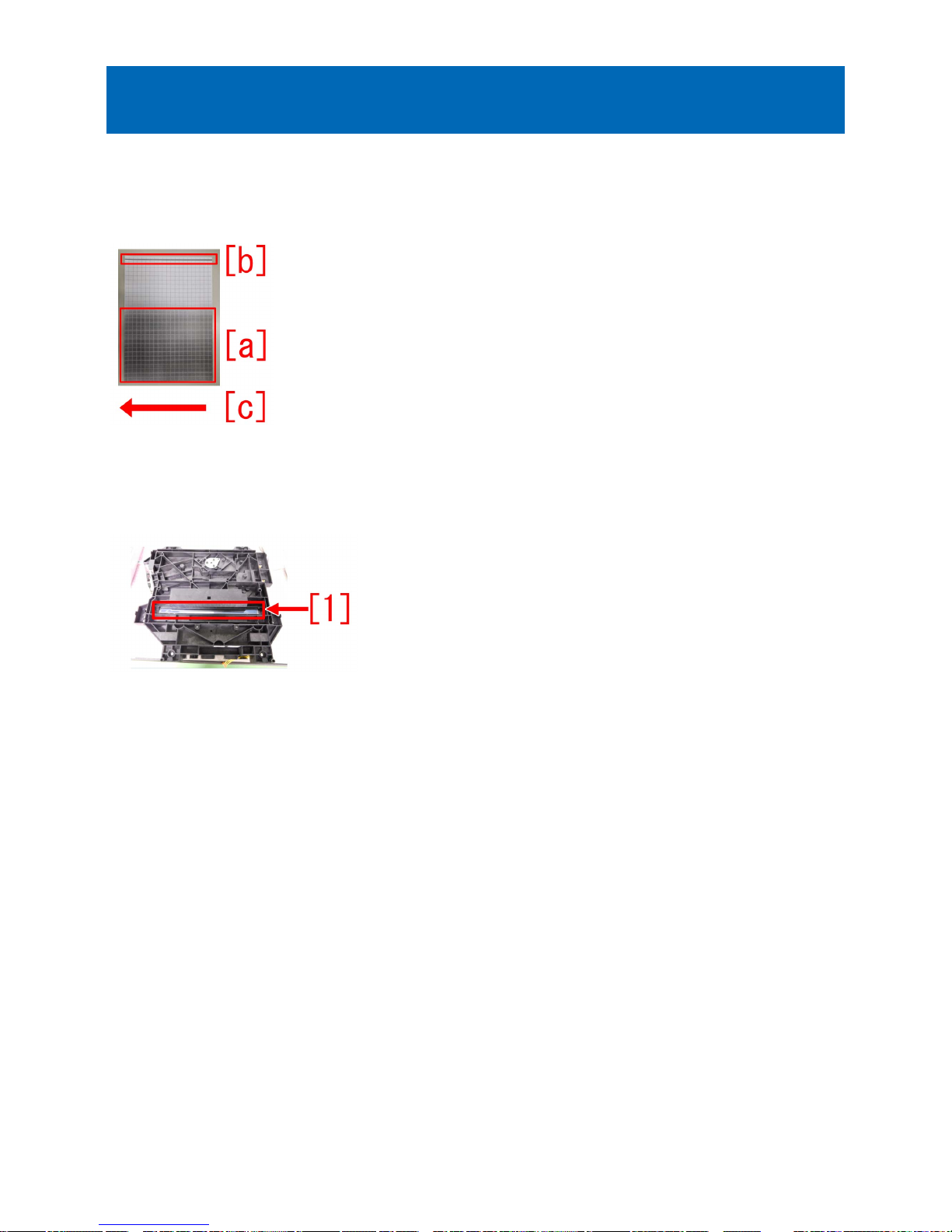
[Symptom]
Black line in sub scanning direction [a] may occur.
The arrow [b] indicates the direction of feeding.
[Cause]
If fluffy foreign matter is adhered to the leaser exposure path which is located between the Laser Scanner Unit and the Developing
Unit, the laser light is blocked and a latent image cannot be formed. As a result, the symptom occurs.
[Service work]
1) Remove the process unit by following the steps in Service Manual "Parts Replacement and Cleaning > Image Formation
System > Cleaning the Process Unit".
2) Remove the developing unit by following the steps in Service Manual "Parts Replacement and Cleaning > Image Formation
System > Removing the Developing Assembly".
3) Check to see if any fluffy foreign matter is attached to the developing sleeve [a] in the developing assembly and remove if
found.
If no fluffy foreign matter is attached, proceed to Step 4).
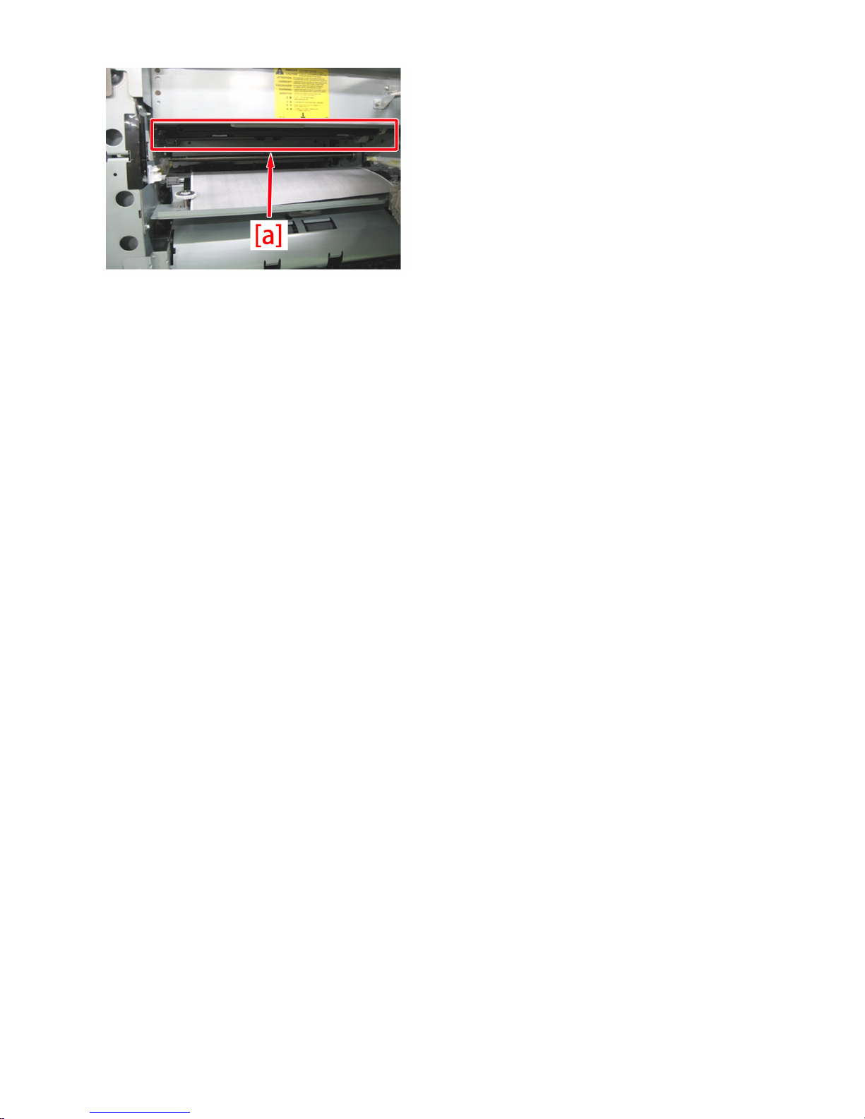
4) Remove the laser scanner unit by following the steps in Service Manual "Parts Replacement and Cleaning > Laser Exposure
System > Removing the Laser Scanner Unit".
5) Check to see if any fluffy foreign matter is attached to the area near [a] the laser scanner unit and remove if found.
1
6) Install the laser scanner unit, developing assembly and process unit by following the steps in Service Manual "Parts
Replacement and Cleaning > Image Formation System.
7) Output the image having shown the symptom, and check that the symptom does not occur.
If the symptom does not improve, check other causes.
2
Measure against soiled image or blank image due to a fault in the
surface finishing of the developing assembly lower sleeve
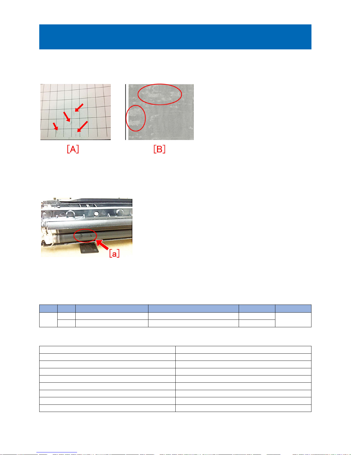
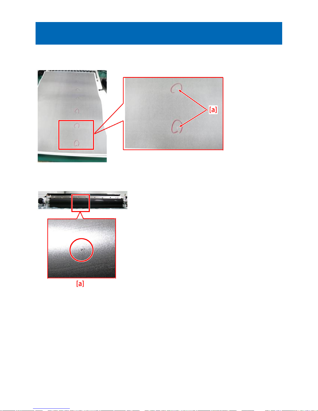
[Symptom]
On the machines with the serial number earlier than the following countermeasure cut-in serial number in factory, soiled image
[A] or blank image [B] may occur directly after machine installation or developing assembly replacement.
[Cause]
If there is a fault in the surface finishing of the developing assembly lower sleeve, the toner is charged more than necessary.
Therefore, toner clump [a] may occur especially in the environment of low temperature and low humidity, resulting in the abovementioned symptom.
[Service work]
Prepare the new-type developing assembly (FM4-5429-010) with the surface finishing process of its lower sleeve changed, and
replace it by referring to service manual.
[Service parts]
No. Part Number Description Q'ty Fig.No.
1 Old FM4-5429-000 DEVELOPING ASS'Y 1 -> 0 640
New FM4-5429-010 DEVELOPING ASS'Y 0 -> 1
[Countermeasure cut-in serial numbers in factory]
Model Serial number
iR-ADV 8505 series 230V AS SWD00727
iR-ADV 8505 series 230V EUR SWC01247
iR-ADV 8505P series 230V EUR TMF00543
iR-ADV 8505i 120V USA SWA01933
iR-ADV 8585i 120V USA SWN01050
iR-ADV 8505i 120V USA G SWB00512
iR-ADV 8585i 120V USA G SWP00505
iR-ADV 8505 series 220V CN WRX00520
- iR-ADV 8105 series /8205 series : No implemented due to production discontinuance.
3
Poor density or white band image due to the boss breakage of the
stirring rod
[Symptom]
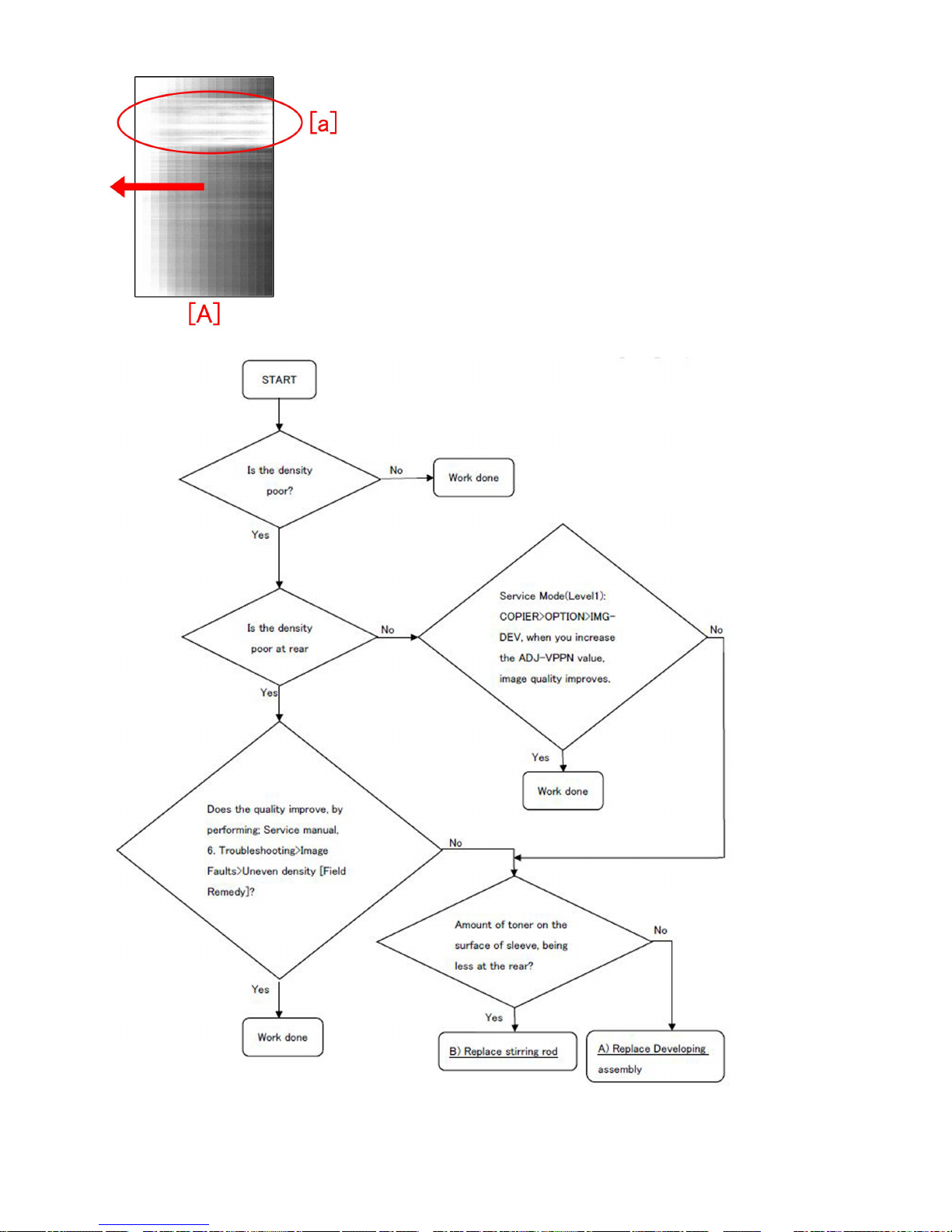
Poor density or white band image may occur in the machine earlier than the following countermeasure cut-in serial numbers in
factory.
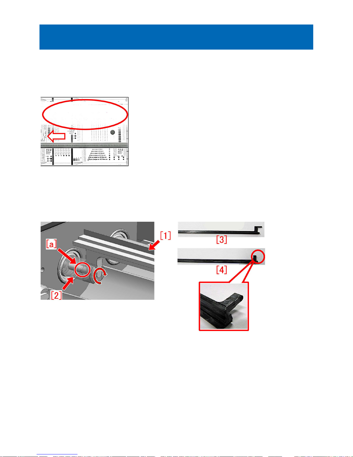
Below is a sample of image with white band phenomenon. Arrow shows the paper feeding direction.
[Cause]
When the stirring sheet [1] of the second stirring rod contacts the container, a stress concentrates to the base of the boss, which
is connected to the 20T gear [2]. Repetitive stress may lead to breakage of the stirring rod, and toner will no more be stirred or
supplied, resulting in the above mentioned phenomenon.
Figures below shows the configuration around the 20T gear and the second stirring rod, normal stirring rod [3] and the broken
stirring rod [4].
[Service work]
When the above symptom occurs, follow the steps below and perform the works.
1) Service Mode(Level1): COPIER > TEST > PG, set value to 3 and conduct test print.
2) Check the test print above 1) and follow the flow chart below to decide what to do.
Figure [A] is a sample of test print with a white band[a] formed in the rear side. Arrow shows the paper feeding direction.
4
3) If necessary, prepare and replace with a new type of either a stirring rod (FL3-2163-010) or a developing assembly
(FM3-7384-020).
5
A) Replacement of developing assembly (FM3-7384-020)
Refer to the service manual and replace with a new type of developing assembly (FM3-7384-020).
B) Replacement of stirring rod (FL3-2163-010)
B-1) Refer to service manual to pull out the developing assembly.
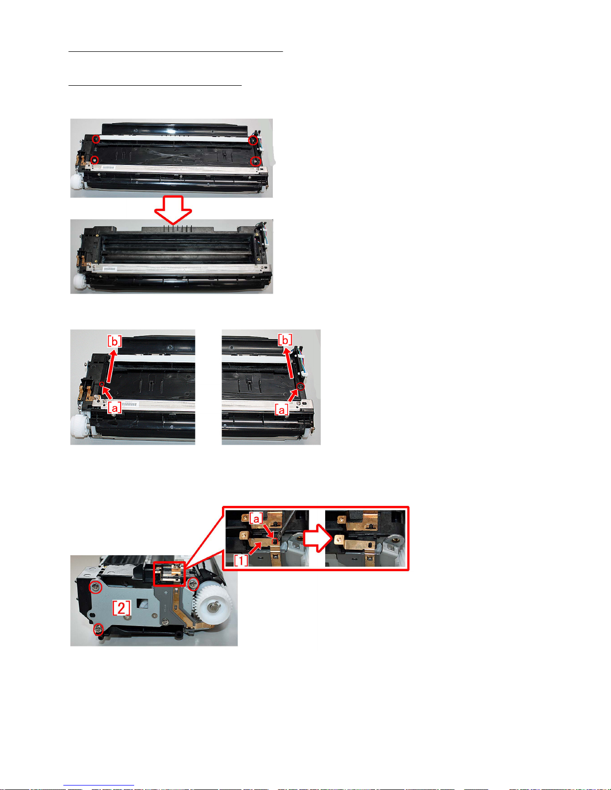
B-2) Remove 4 pcs of screws and remove the lid.
[Reference] To remove the lid, displace the boss [a] from a hole, and then slide the lid towards direction [b].
B-3) Use a vacuum cleaner to remove all toner left in the developing assembly.
B-4) Remove 3pcs of screws, then remove roller bias plate [1] from the boss [a] and remove a metal sheet [2] from the side of
the developing assembly.
[Caution] When you install a metal sheet, be sure the roller bias plate fits into the boss properly.
[A] Roller bias plate in a correct position of boss, [B] Roller bias plate not fitting properly.
6
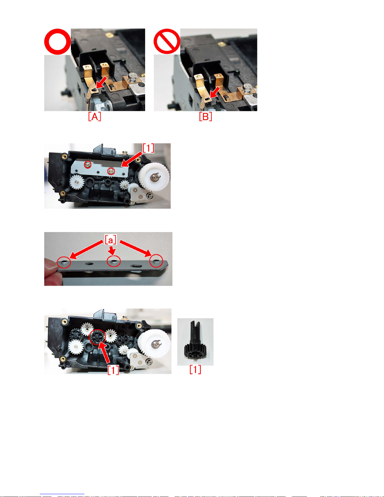
B-5) Remove 2pcs of screws and remove metal sheet [1].
[Caution] When installing a metal sheet, be sure the protrusions [a] come to outer side to fit it.
B-6) Pull out 20Tgear [1].
B-7) Toner or flake of broken part of stirring rod may exist inside the 20Tgear. Set the center hole downward and hit the gear on
a desk several times to cleanup inside the 20Tgear.
7
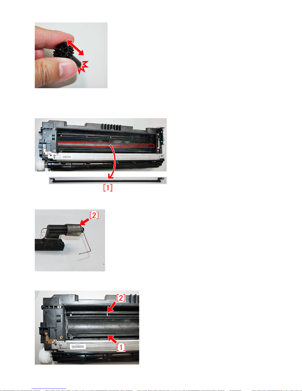
B-8) Pull out a stirring rod [1] where it is at the second stirring rod position in the developing assembly.
[Reference] Photo below shows the normal status of stirring rod [1]. Note that even the stirring rod [1] detached is the normal
status, old type of stirring rod shall be replaced with a new type.
Detach a compression spring [2] from the stirring rod which was taken out, and install it to a new type of stirring rod (FL3-2163-010).
B-9) Let the first stirring rod [1] and the third stirring rod [2] in the developing assembly face each other.
8

B-10) When you install a new type of stirring rod (FL3-2163-010), make sure that the stirring part comes at the downward position.
[Reference] Below is the cross section of the developing assembly. Check the direction of the stirring parts for all 3 rods and
install them in correct positions as below.
B-11) Install the detached 20T gear [1] (procedure B-6), so that its slit comes in a vertical position. In addition, make sure that
the boss [a] of a stirring rod, which was installed in procedure B-10), fits into the middle of the hole on 20T gear [1].
B-12) Reassemble the parts in reverse order from the step B-5).
[Service parts]
No. Part Number Description Q'ty. Fig. No.
1 Old FM3-7384-010 DEVELOPING ASS'Y 1->0
640B
New FM3-7384-020 DEVELOPING ASS'Y 0->1
2 Old FL3-2163-000 ROD, STIRRING 1->0
640B
New FL3-2163-010 ROD, STIRRING 0->1
[Countermeasure cut-in serial numbers in factory]
Model Serial number
iR-ADV 6575 230V AS SMU00864
iR-ADV 6565 230V AS SMK01046
iR-ADV 6555 230V AS SMB01890
iR-ADV 6575 230V EUR SMZ01870
iR-ADV 6565 230V EUR SMQ02248
iR-ADV 6555 230V EUR SMF04649
iR-ADV 6555i 230V EUR PRT TAU00610
iR-ADV 6575i 120V USA SMT05183
iR-ADV 6565i 120V USA SMJ04153
iR-ADV 6555i 120V USA SKA11176
iR-ADV 6575i 120V USA G SMX00670
iR-ADV 6565i 120V USA G SMN00598
iR-ADV 6555i 120V USA G SMD00668
iR-ADV 6575 220V KR SMV00521
iR-ADV 6565 220V KR SML00551
iR-ADV 6555 220V KR WCN00644
9

Model Serial number
iR-ADV 6575 220V CN SPA00563
iR-ADV 6565 220V CN SMR00617
iR-ADV 6555 220V CN SMG00697
iR-ADV 6575i 120V TW SMW00513
iR-ADV 6565i 120V TW SMM00510
iR-ADV 6555i 120V TW SMC00692
iR-ADV 6575i 230V IND SMY00560
iR-ADV 6565i 230V IND SMP00521
iR-ADV 6555i 230V IND SME00872
- iR-ADV 6075/6275 Series: No implemented due to production discontinuance.
10
Foggy image/black lines due to detached dustproof glass inside
the laser scanner unit
[Symptom]
Foggy image [a] and black lines [b] may occur when copying and printing. The number of black lines and the location may not
be constant.
The arrow [c] indicates the paper feed direction.
[Cause]
The double-sided tape attaching the dustproof glass [1] inside the laser scanner unit (FM3-7526-010/FM3-7531-010) is peeled
off due to insufficient pressure, the dustproof glass detaches and drops inside the machine and it obstructs the optical path,
resulting in the above-mentioned symptom.
[Service work]
1) Remove the laser scanner unit by following Service Manual.
2) Check the dustproof glass inside the laser scanner unit. If the dustproof glass is detached, replace it with the new laser scanner
unit. If it is not detached, look for another factor.
3) Return the laser scanner unit.
[ Service parts]
- imageRUNNER ADVANCE 6500 series : FM3-7526-010
- imageRUNNER ADVANCE 8500 series : FM3-7531-010
11
Stained image (at regular intervals of 63mm) due to scratches on
the developing upper/lower cylinder
[Symptom]
Stain (at regular intervals of 63mm) [a] may appear on image when printing.
[Cause]
Scratches [a] on the developing upper/lower cylinder result in the aforementioned symptom.
[Service work]
Prepare and replace with a new developing assembly (FM4-5429-010).
[Attention] Be sure not to scratch on the developing upper/lower cylinder when opening the packing of the developing assembly.
[Service parts]
FM4-5429-010 Developing assembly
12

Faulty Feeding
Inconsistent folding position when using booklet mode with a
small number of sheets due to deflected paper inside the
processing tray (Booklet Finisher-V1/V2/Y1/AA1)
[Symptom]
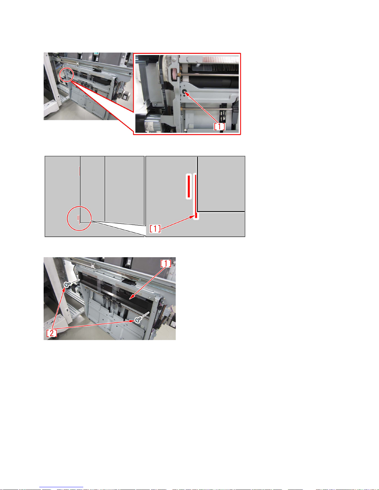
When using the booklet mode with a small number of sheets in the machine earlier than the following countermeasure cut-in
serial numbers in factory, the folding position ([a] and [b]) of the output products [1] may be displaced and inconsistent as shown
in the Figure below. The arrow indicates the feeding direction.
[Cause]
When the paper fed from the feeding unit is stacked on the saddle processing tray, the paper is deflected inside the processing
tray, resulting in the above-mentioned symptom.
[Remedy]
If the above-mentioned-symptom occurs, prepare the new-type roller guide [1] (FL1-5052-000), the new E ring (XD2-1100-325)
and the saddle stopper assembly [2] (FM1-R635-000) which was newly set up as a service part to replace by following the
procedure below. This procedure starts with the step after the booklet finisher is separated from the copier.
1) Step to replace the roller guide
1-1) Referring to "Pulling Out the Saddle Unit (Service Position)" of Service Manual, pull out the saddle unit.
1-2) Remove 1 screw [1] on the rear side of the saddle unit.
13
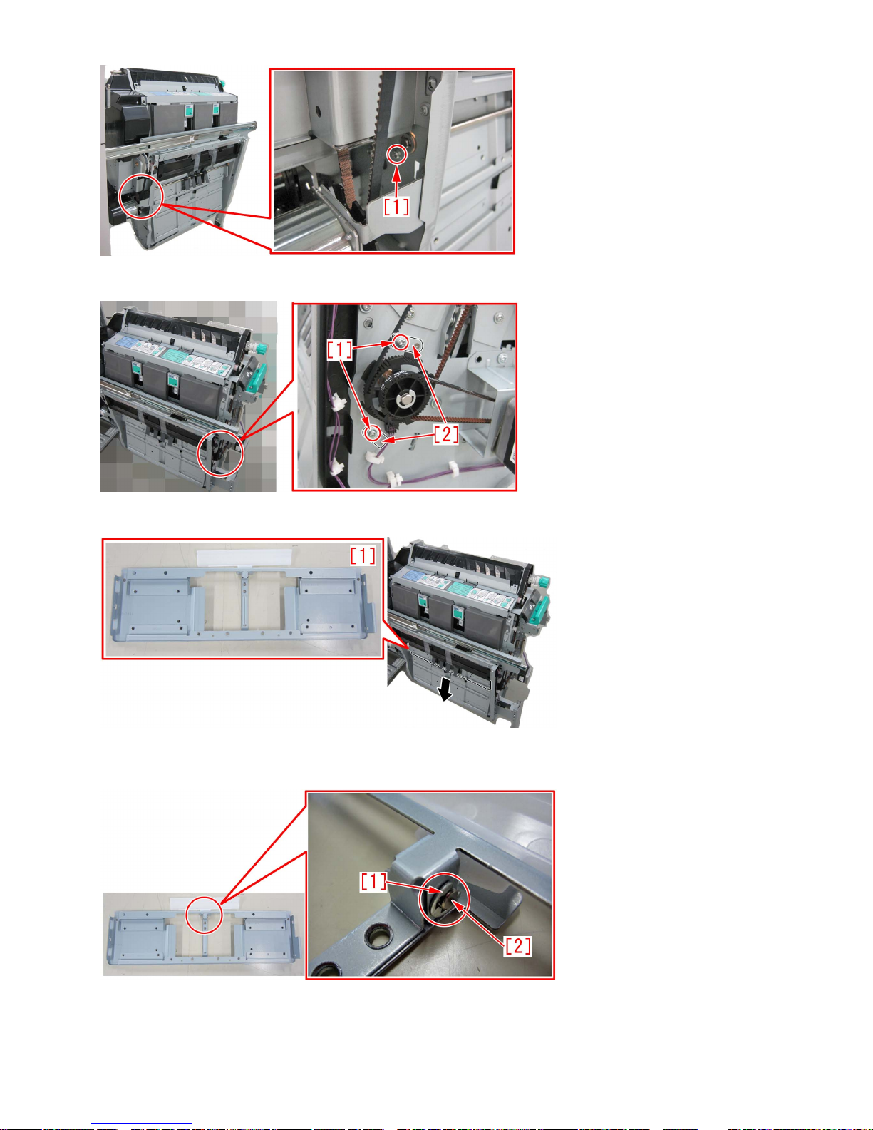
1-3) Remove the 2 screws [1] on the front side of the saddle unit, and remove the 2 support plates [2].
1-4) Remove the roller guide unit [1] in the arrow direction.
1-5) Remove the 1 E ring [1], and remove the 1 shaft [2].
[Attention] The E ring should be replaced with a new one instead of reusing it.
1-6) Remove the compression spring [2] attached to the roller guide [1].
14
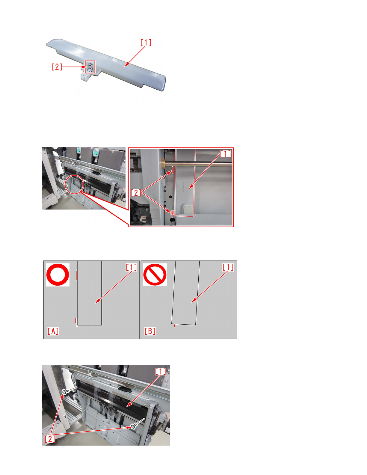
1-7) Replace the roller guide with the new-type roller guide (FL1-5052-000).
1-8) Checking the rear saddle alignment plate
1-8-1) Move the rear saddle alignment plate [1] by hands to the 2 markings (top & bottom) [2] seen on the saddle bracket. Then,
check if it is properly moved to the markings. (Marking at the top and bottom. The bottom marking is located in the center.)
[A] shows the rear saddle alignment plate in the correct position located at the markings at the top and bottom. (The bottom
marking is located in the center.)
[B] shows the skewed rear saddle alignment plate.
1-8-2) If the rear saddle alignment plate is skewed, proceed to next step. If it is in the correct position, proceed to 1-9).
1-8-3) Remove the 2 stepped screws [2] on the delivery guide unit [1].
15
1-8-4) Loosen the fixing screw [1] of the rear saddle alignment plate and fix it according the markings on the bracket.
[Note] When fixing the rear saddle alignment plate, hold the rear saddle alignment plate to avoid having it attached in a skewed
position.
[Note] When attaching the part, match the bottom marking to the marking in the center [1].
1-8-5) Attach the delivery guide unit [1] with the 2 stepped screws [2].
1-9) Attach the parts by reversing the procedure from the step 1-6)
2) Step to replace the saddle stopper assembly
2-1) Referring to "Removing the Saddle Unit" of Service Manual, remove the saddle unit.
2-2) Remove the 2 screws [1], and remove the saddle lower guide [2].
16
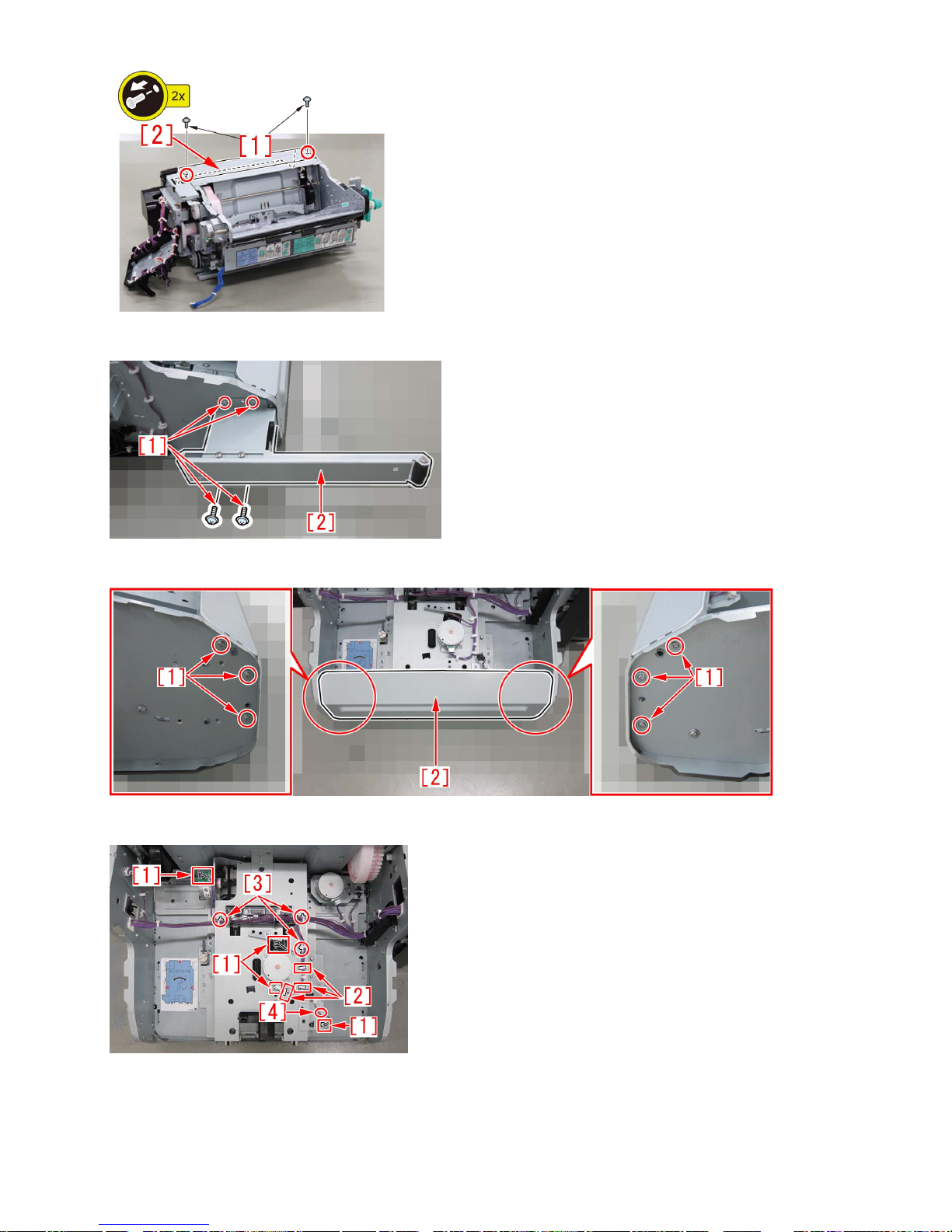
2-3) Remove the 4 screws [1], and remove the saddle unit auxiliary caster [2].
2-4) Remove the 6 screws [1], and remove the cover [2] on the lower side of the saddle unit.
2-5) Remove the 4 connectors [1], 3 wire saddles [2], 3 wire clamps [3] and 1 edge saddle [4].
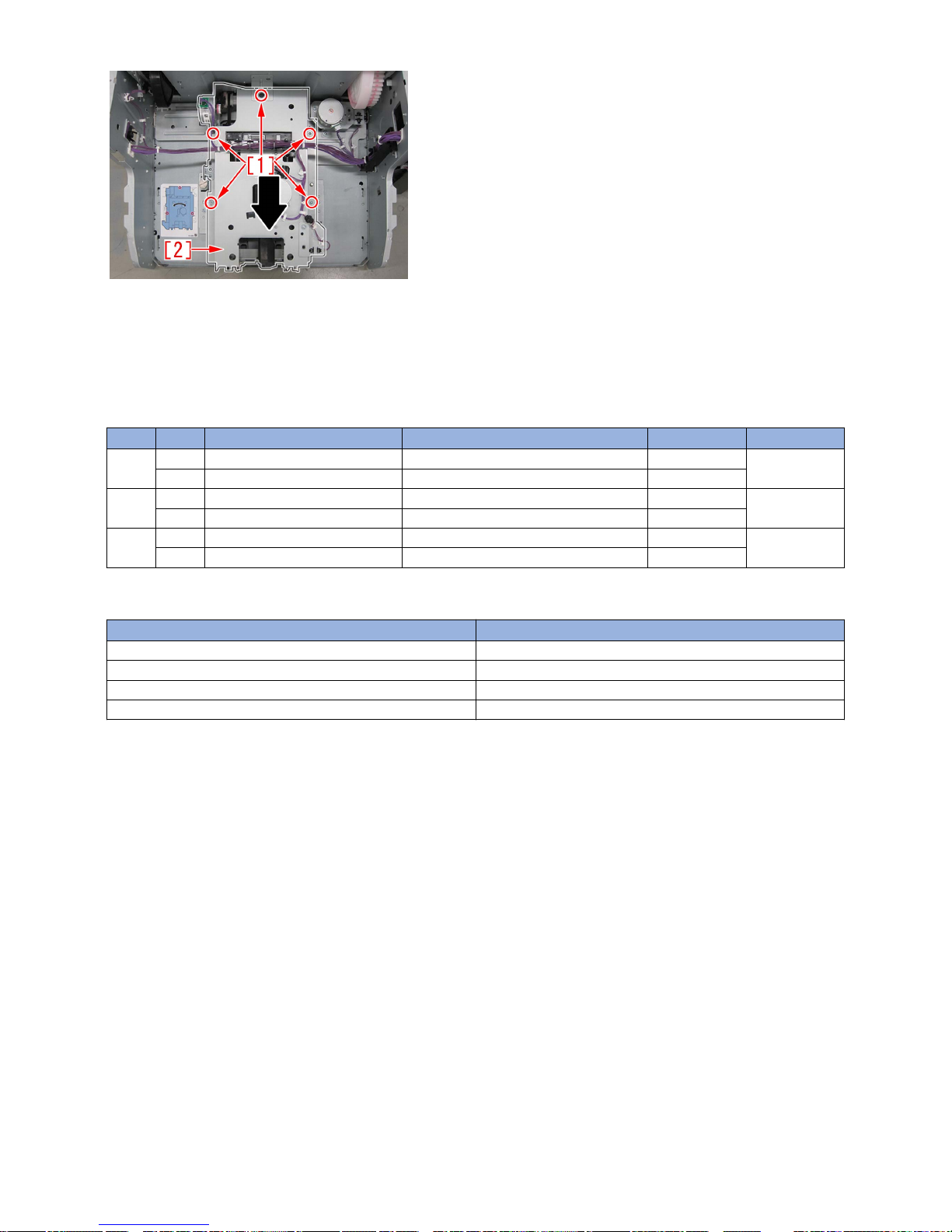
2-6) Remove the 5 screws [1], remove the saddle stopper assembly [2] in the arrow direction, and replace the saddle stopper
assembly with the saddle stopper assembly (FM1-R635-000) which was newly set up as a service part.
[Attention] When pulling out the assembly, don't catch the harness.
17
2-7) Referring to "Adjusting the Saddle Paper End Stopper Installation Angle" of Service Manual, adjust the saddle paper end
stopper installation angle.
2-8) Referring to Service Manual, perform "Adjusting the folding position of the saddle stitcher unit" and "Adjusting the stitching
position of the saddle stitcher unit".
2-9) Attach the parts by reversing the procedure from the step 2-5).
[Service parts]
No. Part Number Description Q'ty Fig.No.
1 Old FE3-7245-000 GUIDE,ROLLER 1 -> 0 L50
New FL1-5052-000 GUIDE,ROLLER 0 -> 1
2 Old
New FM1-R635-000 Saddle Stopper Assembly 0 -> 1
3 Old XD2-1100-325 RING, E 1 -> 1
New
[Countermeasure cut-in serial numbers in factory]
Model Serial number
Booklet Finisher-V1 No implemented due to production discontinuance
Booklet Finisher-V2 WXB04698
Booklet Finisher-Y1 WEY14510
Booklet Finisher-AA1 EX WWD01265
18
Malfunction
When using the manual stapler, staple position is shifted and
sheets are not stapled due to a spring coming off. (Staple FinisherV1, Booklet Finisher-V1)
[Symptom]
When using the manual stapler, staple position may be shifted and sheets may not be stapled due to a spring coming off.
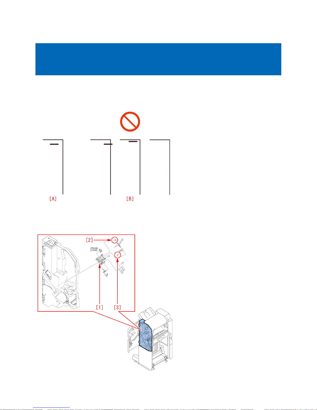
Fig.[A] shows correct stapling. Fig.[B] shows incorrect staple positions and missing staples.
[Cause]
The torsion spring [2] or the tension spring [3] of the sensor holder [1] in the inner cover assembly comes off. It results in
misdetection by sensor flags causing the above symptom.
19
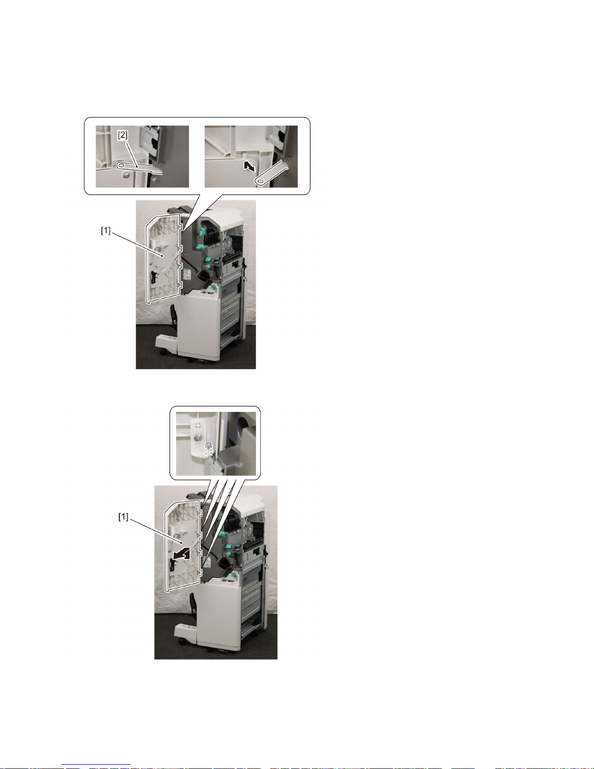
[Service work]
When the above symptom occurs, follow the steps below.
The procedure starts from where the finisher is removed from the main body.
1) Open the front cover [1], and remove the link [2].
2) Remove the front cover [1].
3) Remove the face cover [1].
- 1 screw [2]
[Note] The face cover [1] is connected only to the staple finisher.
20
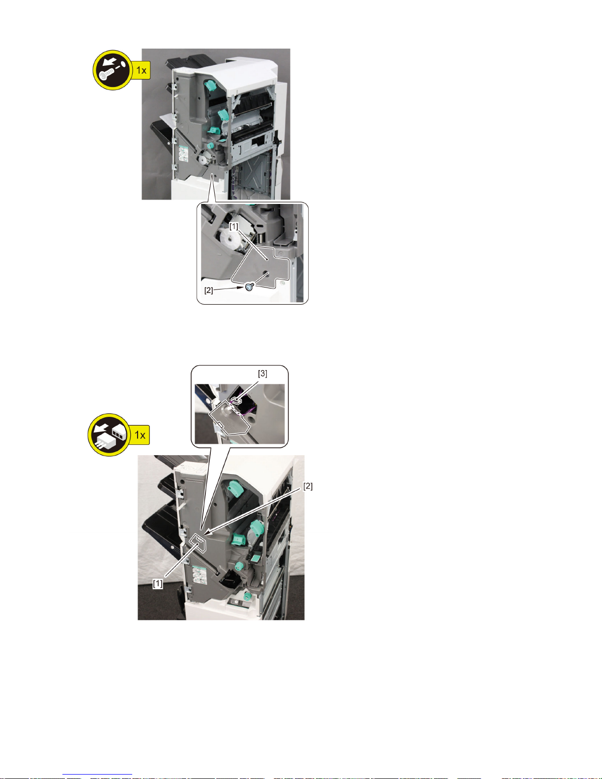
4) Remove the face plate [1].
- 1 claw [2]
- 1 connector [3]
5) Avoid the guide, and remove the front inner cover [1].
- 6 screws [2]
21
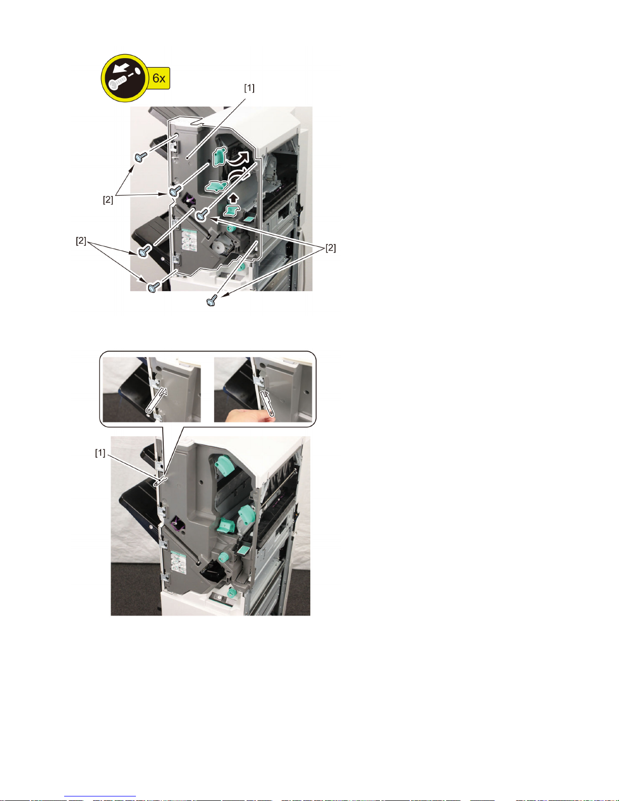
[Note] Be careful not to drop the link [1] as it comes off easily.
[Note] Escape the punch unit when it is installed.
6) Remove the sensor holder [1] located in back of the front inner cover.
- 2 screws [2]
- Connector [3]
22
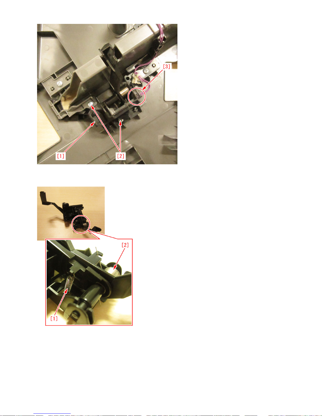
7) Check whether the torsion spring [1] and tension spring [2] in the sensor holder come off. If the springs are not in normal place,
place them back in the correct positions.
8) Attach all the parts in the reverse order from the step 6).
23
Message is wrongly displayed due to the displaced waste staple
case (Staple Finisher-X1 / Booklet Finisher-X1 / Staple FinisherN1 / Booklet Finisher-N1)
[Symptom]
Even though the waste staple case is not full, the following message may be displayed.
Model Message
iR-ADV 8200 Series Check the staple waste tray.
iR-ADV 8500 Series
[Cause]
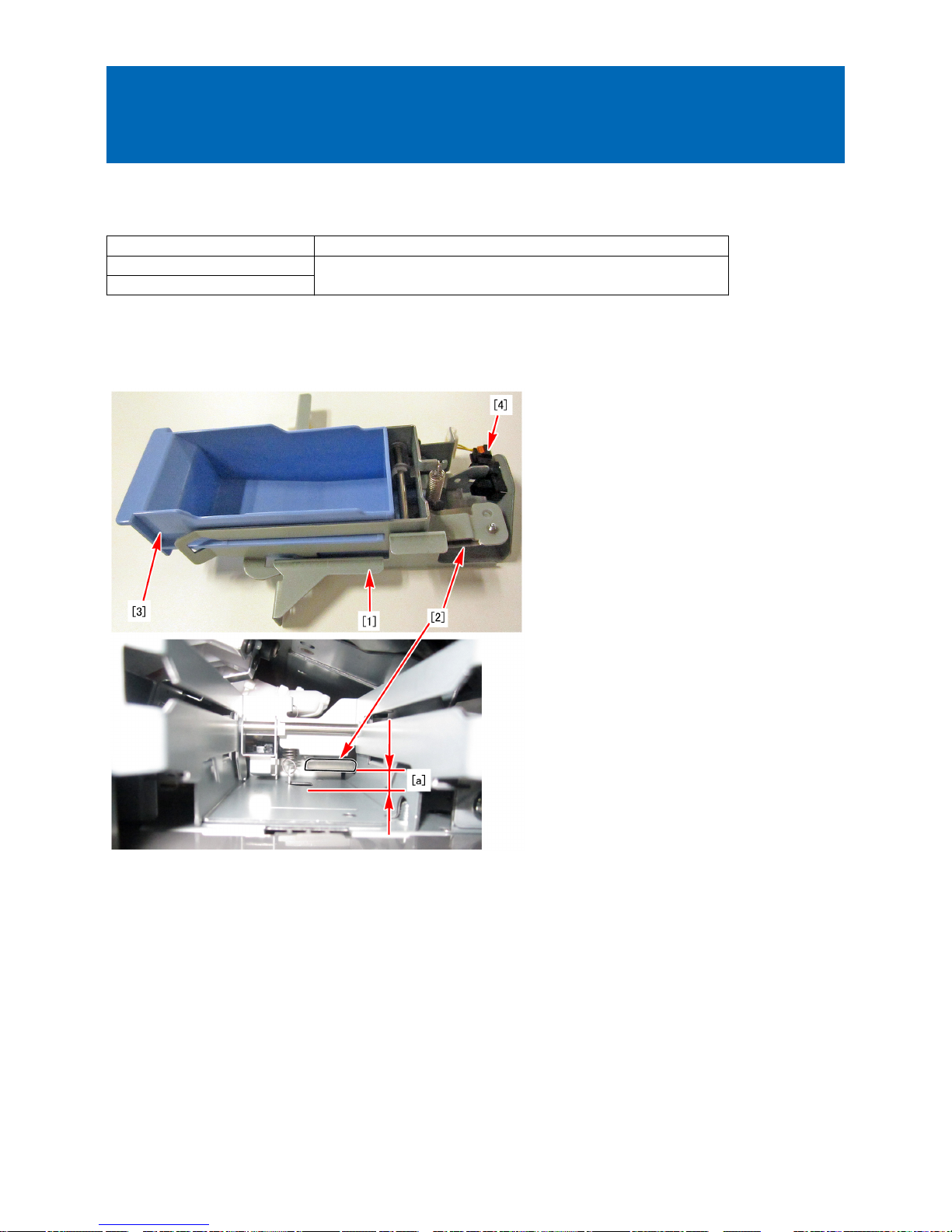
Due to the high position [a] of the leaf spring [2] of the staple collect unit [1], the waste staple case [3] is loosely fixed, the waste
staple case is displaced, and the needle chip full sensor [4] detects falsely, which causes the above-mentioned symptom.
[Service work]
If the above-mentioned symptom occurs, add the shim (XD1-1104-635) by following the procedures below.
Adding the shim and lowering the position of the leaf spring [1] will fix the waste staple case [2] more firmly and it will become
less prone to be displaced.
24
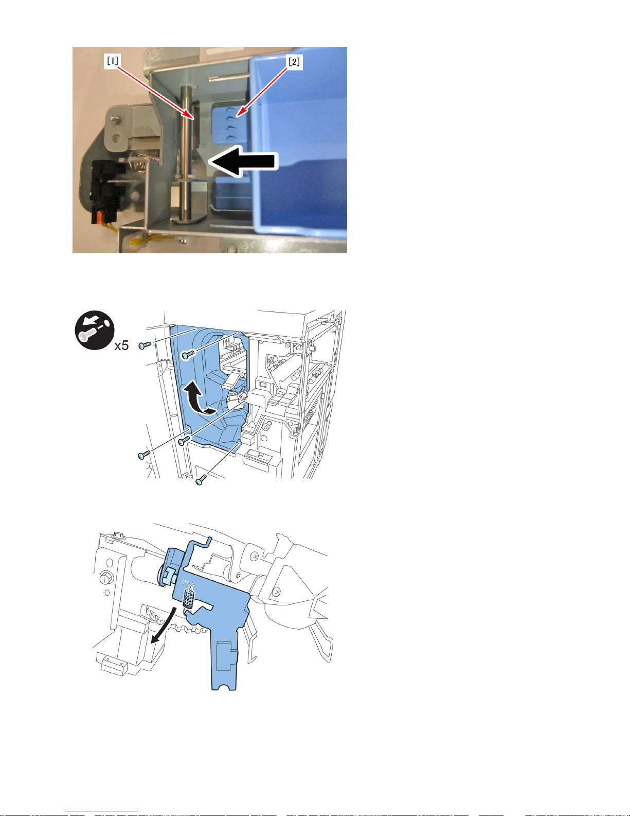
1) Open the front door.
2) Remove the 5 screws and remove the left inner cover.
3) Remove the clip, shaft and spring to remove the stapler stopper.
4) Remove the waste staple case.
25
 Loading...