

Canon SmartBase MPC400, SmartBase MPC600F, imageCLASS MPC600F, imageCLASS MPC400 Parts Catalog
REVISION 1
COPYRIGHT © 2002 CANON INC. CANON SmartBase MPC600F/MPC400 imageCLASS MPC600F/MPC400 FEB. 2002
HY8-30AP-010
FEB. 2002
SmartBase MPC600F H12-2194 230V ENG
SmartBase MPC600F H12-2195 230V GER
SmartBase MPC600F H12-2197 230V FRN
SmartBase MPC400 H12-2204 230V EC
imageCLASS MPC600F H12-2198 230V AUS
imageCLASS MPC600F H12-2199 230V AE
imageCLASS MPC600F H12-2196 230V CHN
imageCLASS MPC400 H12-2208 230V AUS
imageCLASS MPC400 H12-2209 230V AE
imageCLASS MPC400 H12-2206 230V CHN

Application
This manual has been issued by Canon Inc. for qualified persons to learn technical theory, installation, maintenance,
and repair of products. This manual covers all localities where the products are sold. For this reason, there may be
information in this manual that does not apply to your locality.
Corrections
This manual may contain technical inaccuracies or typographical errors due to improvements or changes in products.
When changes occur in applicable products or in the content of this manual, Canon will release technical information
as the need arises. In the event of major changes in the contents of this manual, Canon will issue a new editions of
this manual.
The following paragraph does not apply to any countries where such provisions are inconsistent with local law.
Trademarks
The product names and company names described in this manual are the registered trademarks of the individual
companies.
Copyright
This manual is copyrighted with all rights reserved. Under the copyright laws, this manual may not be copied,
reproduced or translated into another language, in whole or in part, without the written consent of Canon Inc.
Copyright © 2002 by Canon Inc.
CANON INC.
Consumer Imaging Products Quality Assurance Dept. 1
5-1 Hakusan 7-Chome, T oride-city , Ibaraki 302-8501, Japan
DTP System
The data contained on this manual were created using Windows NT® computers.
Document creation and page layout were performed using Adobe® PageMaker® 6.5.
Logos and illustrations were created using Adobe® Illustrator® 9.0.

I
I. CONTENTS
1. ILLUSTRATION INDEX
2. PARTS LAYOUT & PARTS LIST
3. TOOL
4. LUBRICATIONS
5. NUMERICAL INDEX

II
II. ABOUT THIS MANUAL
1. ILLUSTRATION INDEX
For illustration index, the parts layout illustrations in
this parts catalog are listed in
abbreviated form in order of illustration number to
identify the pages they appear on. To find an
illustration of a part, see the ILLUSTRA TION INDEX.
2. PARTS LAYOUT & PARTS LIST
Parts layout illustration
a) Parts search
Find a part from the parts layout illustration and
find its key number from the parts list to identify
the part number and name.
Further, screws, nuts, washers, grip rings, pins and
spacers are mentioned in the parts list.
Note: If parts have the same or similar shape but
different specifications,
their key number is assigned to several part
numbers and names in the parts list.
b) Parts replacement procedure
The parts layout illustrations are arranged according
to the disassembly procedure of the product.
When a unit in the illustration can be disassemble
further, a reference illustration page of the
disassembly will be included.
Parts where grease is to be applied are displayed as
"Lubrication". When replacing parts, or if grease
has accidentally been wiped off, refer to "4".
(Lubrications), and reapply the grease.
The letters ( A , B etc.) in the illustration indicate
the connection locations of cables and screws.
Parts list
a) FIGURE & KEY No.
The FIGURE & KEY No. column corresponds to
the key numbers assigned to the parts in the parts
layout illustration.
It also corresponds to the part locations printed on
the PC board.
b) P ART NUMBER
The PART NUMBER column gives the part
numbers corresponding to the key numbers. To
order a part, indicate the part number clearly.
Note: Parts marked NPN are not service parts.
c) RANK
The service parts with N in the RANK column are
order parts.
d) QTY
The QTY column gives the number of parts in the
corresponding components layout illustration.
e) DESCRIPTION
The DESCRIPTION column gives the part names
in English.
To order a part, indicate the part name, too.
3. TOOL
This is a list of tools used for servicing products.
4. LUBRICATIONS
Where grease is to be applied in order to allow moving
parts to work smoothly, and to increase conductivity,
the type and amount of grease to be used will be
mentioned.
5. NUMERICAL INDEX
All the parts listed in this parts catalog are arranged in
order of part number. You can identify part locations
and names from the NUMERICAL INDEX.
1-1
1. ILLUSTRATION INDEX
SmartBase MPC600F/MPC400 imageCLASS MPC600F/MPC400
1.ILLUSTRATION INDEX
See page
2-1
FIGURE 1
See page
2-3
See page
2-5
See page
2-7
FIGURE 2
FIGURE 3 FIGURE 4
5
4
1
3
6
2
7
See FIGURE 1
0
for disassemb
ly
1
2
4
3
5
1
2
6
6
6
4
3
5
1
2
3
See FIGURE 1
1
for disassemb
ly
SmartBase MPC600F/
imageCLASS MPC600F
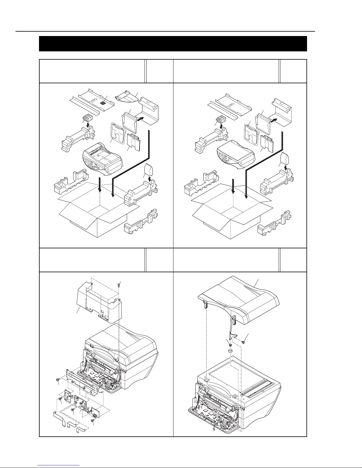
PACKAGE CONTENTS
SmartBase MPC600F/imageCLASS MPC600F
REAR COVER, NCU BOARD,
MODEM BOARD
SmartBase MPC600F/
imageCLASS MPC600F
DOCUMENT FEED ASS’Y
SmartBase MPC400/
imageCLASS MPC400
PACKAGE CONTENTS
1-2
SmartBase MPC600F/MPC400 imageCLASS MPC600F/MPC400
1.ILLUSTRATION INDEX
See page
2-9
See page
2-11
See page
2-13
See page
2-15
FIGURE 5 FIGURE 6
FIGURE 7 FIGURE 8
1
5
2
3
4
1
3
5
2
4
4
See FIGURE 1
5
for disassemb
ly
1
2
3
2
S
ee FIGURE 17
for disassembly
1
3
4
4
2
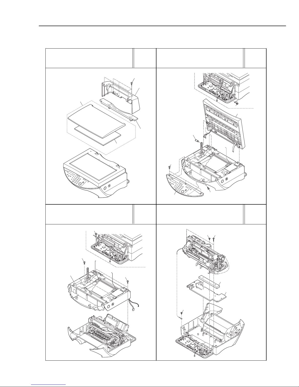
SmartBase MPC400/imageCLASS MPC400
REAR COVER, PRESSURE
PLATE
FLAT BED ASS’Y,
OPERATION PANEL UNIT
MIDDLE COVER ASS’Y PRINT & ASF ASS’Y
1-3
SmartBase MPC600F/MPC400 imageCLASS MPC600F/MPC400
1.ILLUSTRATION INDEX
See page
2-17
See page
2-19
See page
2-21
FIGURE 9 FIGURE 10
FIGURE 11
See page
2-23
FIGURE 12
2
1
8
8
8
8
5
4
3
9
9
7
8
8
6
See FIGURE 25
for disassembly
5
6
6
2
4
3
1
2
7
5
6
6
1
3
9
4
8
1
4
2
6
3
3
8
9
5
1
0
11
10
10
10
7
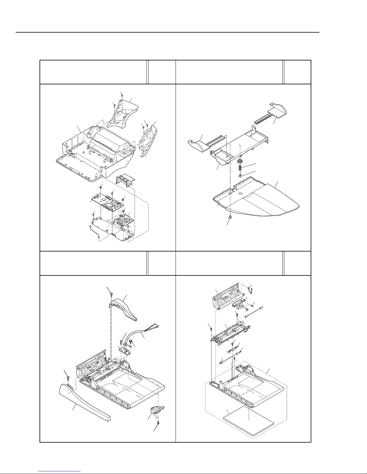
FRONT COVER,
SCNT BOARD,
POWER SUPPLY
SmartBase MPC600F/
imageCLASS MPC600F
DOCUMENT FEED ASS’Y(1)
SmartBase MPC600F/
imageCLASS MPC600F
DOCUMENT FEED ASS’Y (2)
SmartBase MPC600F/
imageCLASS MPC600F
DOCUMENT TRAY
1-4
SmartBase MPC600F/MPC400 imageCLASS MPC600F/MPC400
1.ILLUSTRATION INDEX
See page
2-25
See page
2-27
See page
2-29
See page
2-31
FIGURE 13 FIGURE 14
FIGURE 15 FIGURE 16
4
13
9
3
1
5
7
8
2
10
10
*
*
12
6
11
*= Lubrication
See page 4-
1
1
19
3
12
16
16
16
13
20
15
4
5
9
9
17
24
24
22
23
21
2
1
2
2
17
16
16
16
14
8
18
7
7
8
2
19
10
6
6
11
13
*
*
*
*
*
*
*
*
*
*
*
*
*
2
0
*= Lubrication
See page 4-1
4
3
2
*
*
7
7
2
1
6
5
8
*= Lubrication
See page 4-2, 4-3
2
5
*
*
*
*
1
9
9
4
6
7
7
8
8
3
*= Lubrication
See page 4-4, 4-5
SmartBase MPC600F/
imageCLASS MPC600F
DOCUMENT FEED SECTION (1)
SmartBase MPC600F/
imageCLASS MPC600F
DOCUMENT FEED SECTION (2)
DOCUMENT GLASS,
CONTACT SENSOR
FLAT BED MOTOR
1-5
SmartBase MPC600F/MPC400 imageCLASS MPC600F/MPC400
1.ILLUSTRATION INDEX
See page
2-33
See page
2-35
See page
2-37
See page
2-39
FIGURE 17 FIGURE 18
FIGURE 19 FIGURE 20
2
1
4
*
*
5
5
7
3
7
6
6
6
7
7
6
6
*= Lubrication
See page 4-5
3
2
1
4
5
5
5
5
5
4
5
6
5
3
1
2
5
4
4
3
2
1
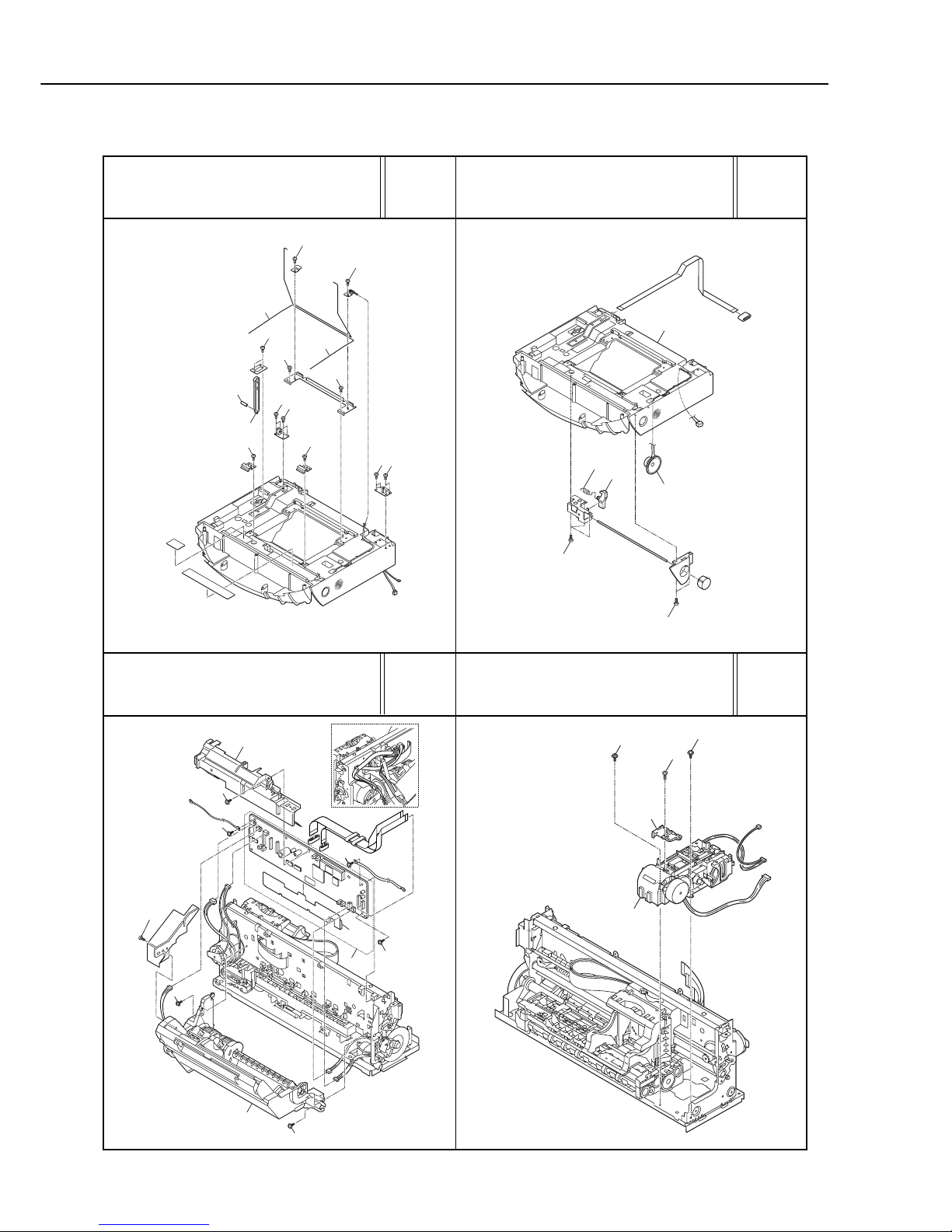
MIDDLE COVER ASS’Y
(1)
MIDDLE COVER ASS’Y
(2)
AUTO SHEET FEEDER,
PCNT BOARD
PURGE UNIT
1-6
SmartBase MPC600F/MPC400 imageCLASS MPC600F/MPC400
1.ILLUSTRATION INDEX
See page
2-41
See page
2-43
See page
2-45
See page
2-47
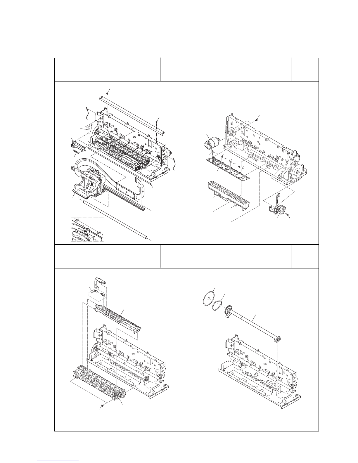
FIGURE 21 FIGURE 22
FIGURE 23
CARRIAGE UNIT
CARRIAGE MOTOR,
TIMING SENSOR
PAPER FEED SECTION
FIGURE 24
6
*
*
*
6
1
2
3
5
4
*= Lubrication
See page 4-6
5
4
1
1
2
5
3
1
1
2
3
1
4
2
1
3
PAPER FEED ROLLER
1-7
SmartBase MPC600F/MPC400 imageCLASS MPC600F/MPC400
1.ILLUSTRATION INDEX
See page
2-49
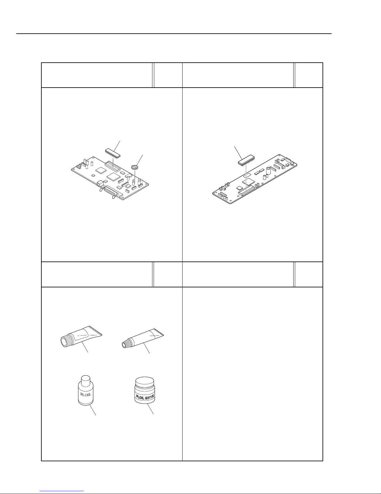
FIGURE 25
FIGURE 27
SCNT BOARD
See page
3-1
TOOLS
See page
2-51
FIGURE 26
PCNT BOARD
BAT
1
IC201
IC8
T1
T2
T3
T4

2-1
SmartBase MPC600F/MPC400 imageCLASS MPC600F/MPC400
2.PARTS LAYOUT & PARTS LIST
2. PARTS LAYOUT & PARTS LIST
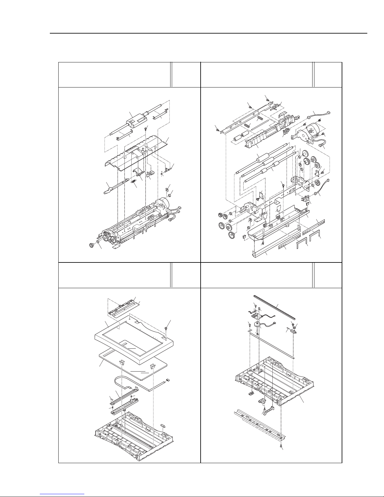
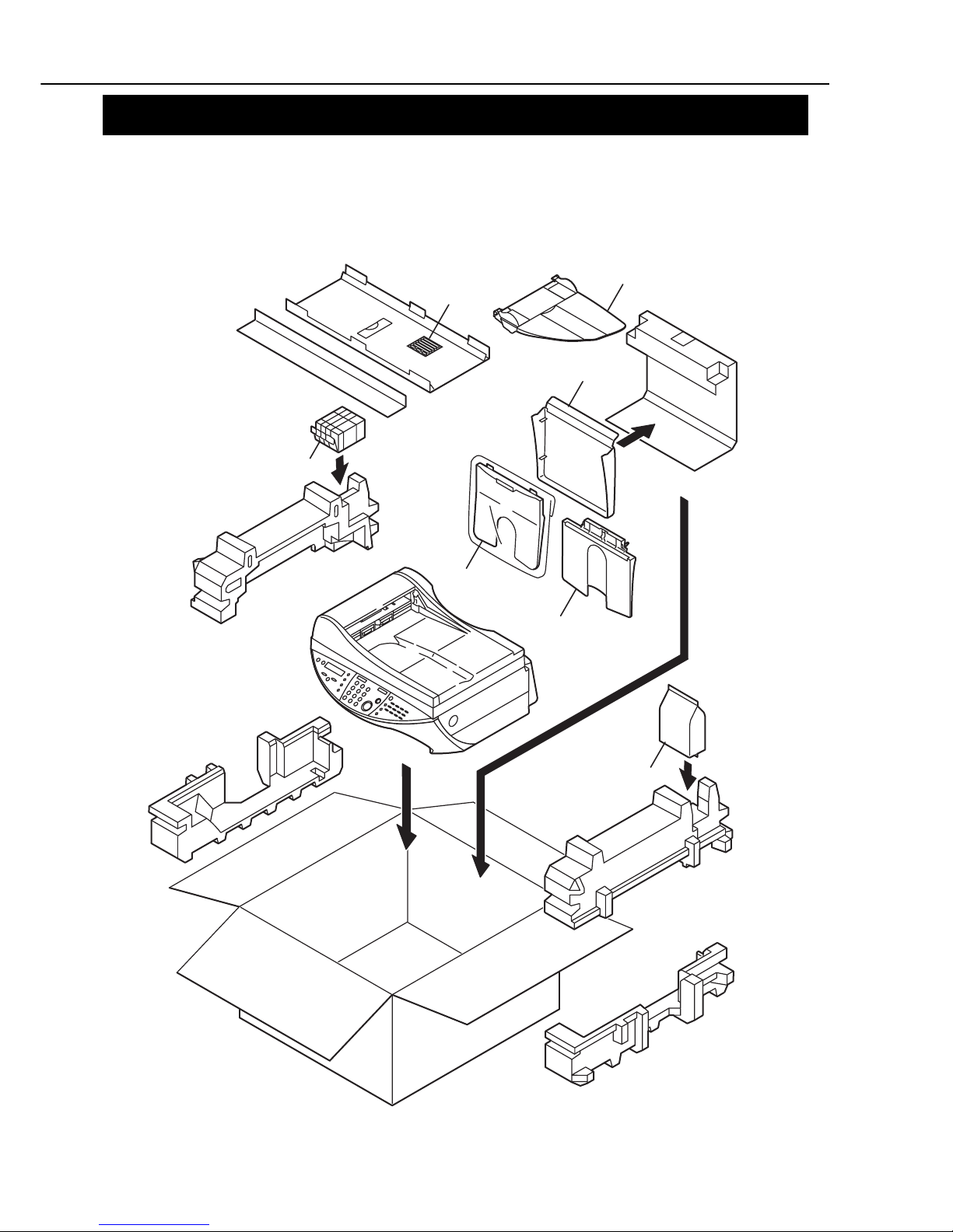
FIGURE 1
SmartBase MPC600F / imageCLASS MPC600F
PACKAGE CONTENTS
5
4
1
3
6
2
7
See FIGURE 1
0
for disassemb
ly

2-2
SmartBase MPC600F/MPC400 imageCLASS MPC600F/MPC400
2.PARTS LAYOUT & PARTS LIST
FIGURE
&
KEY No.
PART No.
R
A
N
K
Q
T
Y
DESCRIPTION REMARKS
1- 1 HC1-0005-000 1 TRAY, RAPER, EXIT
2 HC1-0006-000 1 TRAY, PAPER
3 HC1-0008-000 1 COVER, P APER TRAY
4 HC1-0035-000 1 LABEL, DESTINATION
5 QY6-0034-000 1 PRINT HEAD
6 NPN 1 DOCUMENT TRAY ASS’Y
7 NPN 1 INK TANK SET
8 HH4-3625-000 N 1 CD-ROM, PRINTRE DRIVER MPC600F AUS AE CHN
9 HH2-2478-000 1 MODULAR CORD, 2P MPC600F AUS
HH2-2824-000 1 MODULAR CORD, 2P MPC600F AE CHN
10 WT3-5139-000 1 CORD, POWER SUPPLY MPC600F CHN
WT3-5140-000 1 CORD, POWER SUPPLY MPC600F AE
WT3-5141-000 1 CORD, POWER SUPPLY MPC600F AUS
11 HT1-2185-000 N 1 USER’S GUIDE (ENGLISH) MPC600F AUS AE
HT1-6048-000 N 1 USER’S GUIDE (CHINESE) MPC600F CHN
12 HT1-2186-000 N 1 USER’S GUIDE, FAX (ENGLISH) MPC600F AUS AE
HT1-6049-000 N 1 USER’S GUIDE, FAX (CHINESE) MPC600F CHN
2-3
SmartBase MPC600F/MPC400 imageCLASS MPC600F/MPC400
2.PARTS LAYOUT & PARTS LIST
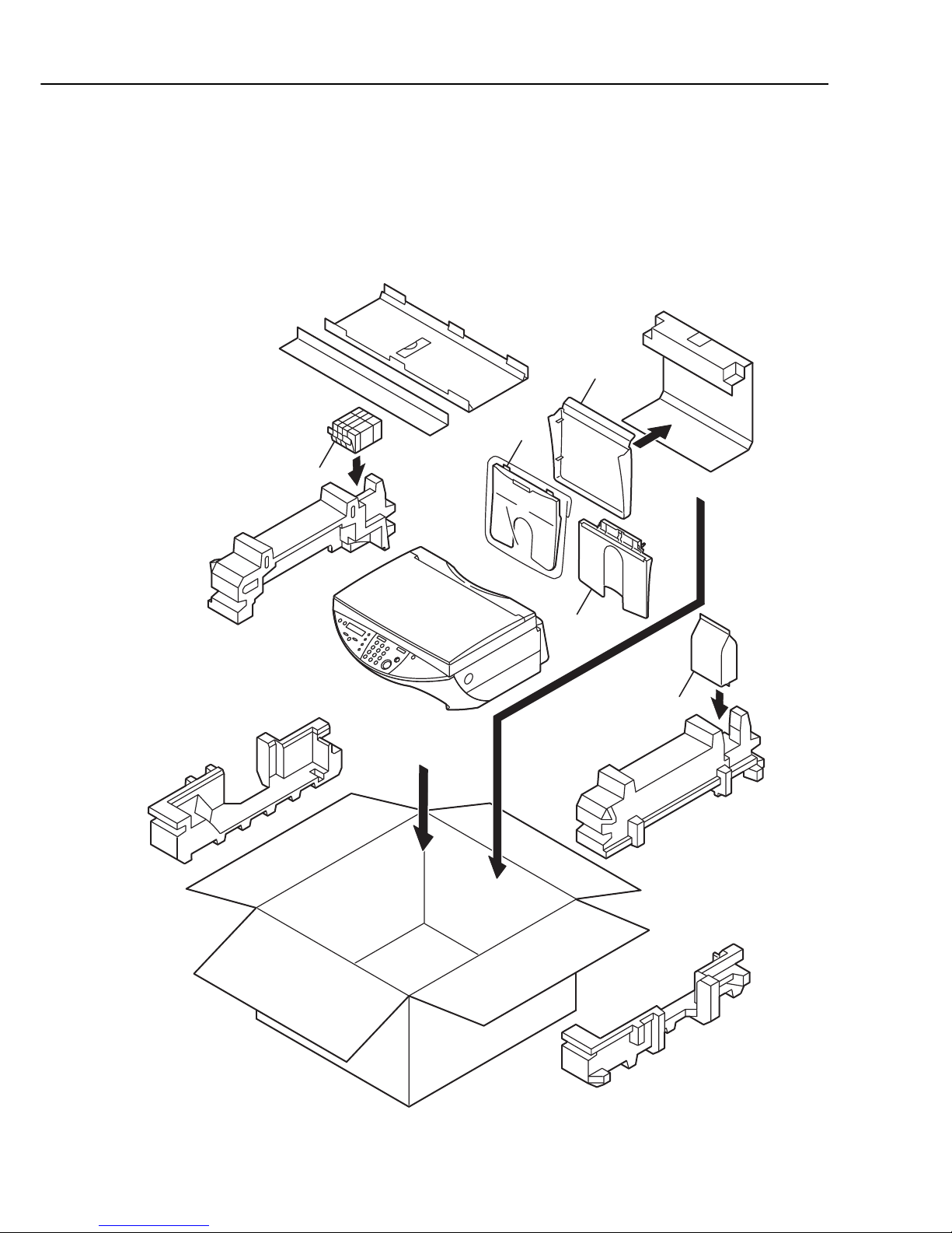
FIGURE 2
SmartBase MPC400 / imageCLASS MPC400
PACKAGE CONTENTS
1
2
4
3
5

2-4
SmartBase MPC600F/MPC400 imageCLASS MPC600F/MPC400
2.PARTS LAYOUT & PARTS LIST
FIGURE
&
KEY No.
PART No.
R
A
N
K
Q
T
Y
DESCRIPTION REMARKS
2- 1 HC1-0005-000 1 TRAY, RAPER, EXIT
2 HC1-0006-000 1 TRAY, PAPER
3 HC1-0008-000 1 COVER, P APER TRAY
4 QY6-0034-000 1 PRINT HEAD
5 NPN 1 INK TANK SET
6 HH4-3625-000 N 1 CD-ROM, PRINTRE DRIVER MPC400 AUS AE CHN
7 WT3-5139-000 1 CORD, POWER SUPPLY MPC400 CHN
WT3-5140-000 1 CORD, POWER SUPPLY MPC400 AE
WT3-5141-000 1 CORD, POWER SUPPLY MPC400 AUS
8 HT1-2185-000 N 1 USER’S GUIDE (ENGLISH) MPC400F AUS AE
HT1-6048-000 N 1 USER’S GUIDE (CHINESE) MPC400 CHN
2-5
SmartBase MPC600F/MPC400 imageCLASS MPC600F/MPC400
2.PARTS LAYOUT & PARTS LIST
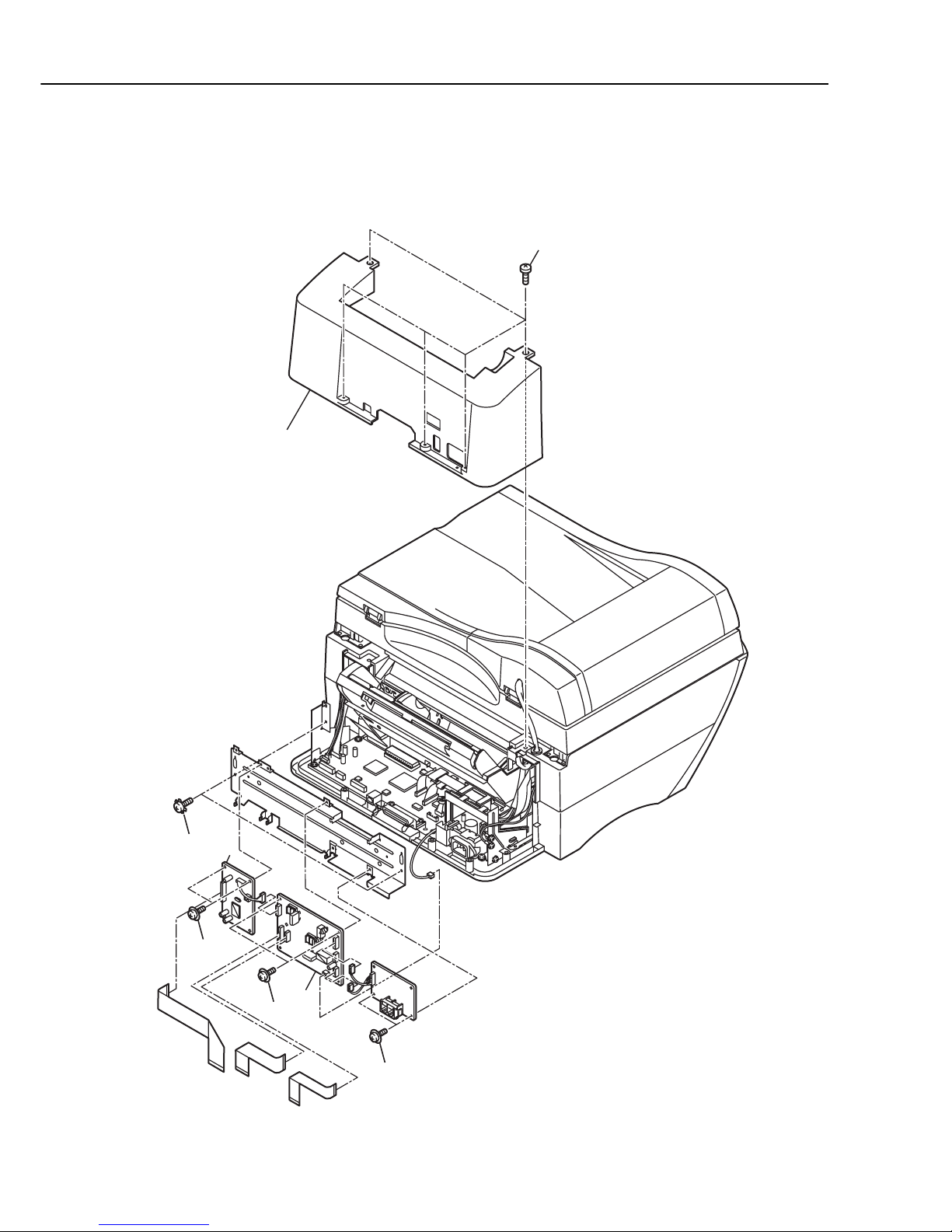
FIGURE 3
SmartBase MPC600F / imageCLASS MPC600F
REAR COVER, NCU BOARD, MODEM BOARD
1
2
6
6
6
4
3
5

2-6
SmartBase MPC600F/MPC400 imageCLASS MPC600F/MPC400
2.PARTS LAYOUT & PARTS LIST
FIGURE
&
KEY No.
PART No.
R
A
N
K
Q
T
Y
DESCRIPTION REMARKS
3- 1 HC1-0002-000 1 COVER, REAR
2 HG5-2587-000 1 NCU BOARD ASS’Y MPC600F ENG GER FRN
HG5-2598-000 1 NCU BOARD ASS’Y MPC600F AUS AE CHN
3 HG1-4391-000 1 MODEM BOARD ASS’Y
4 XB2-7300-607 2 SCREW, M3X6
5 XB4-7300-807 5 SCREW, TAP TIGHT, BINDING HEAD
6 XB6-7300-407 6 SCREW, TP, PH M3X4
2-7
SmartBase MPC600F/MPC400 imageCLASS MPC600F/MPC400
2.PARTS LAYOUT & PARTS LIST
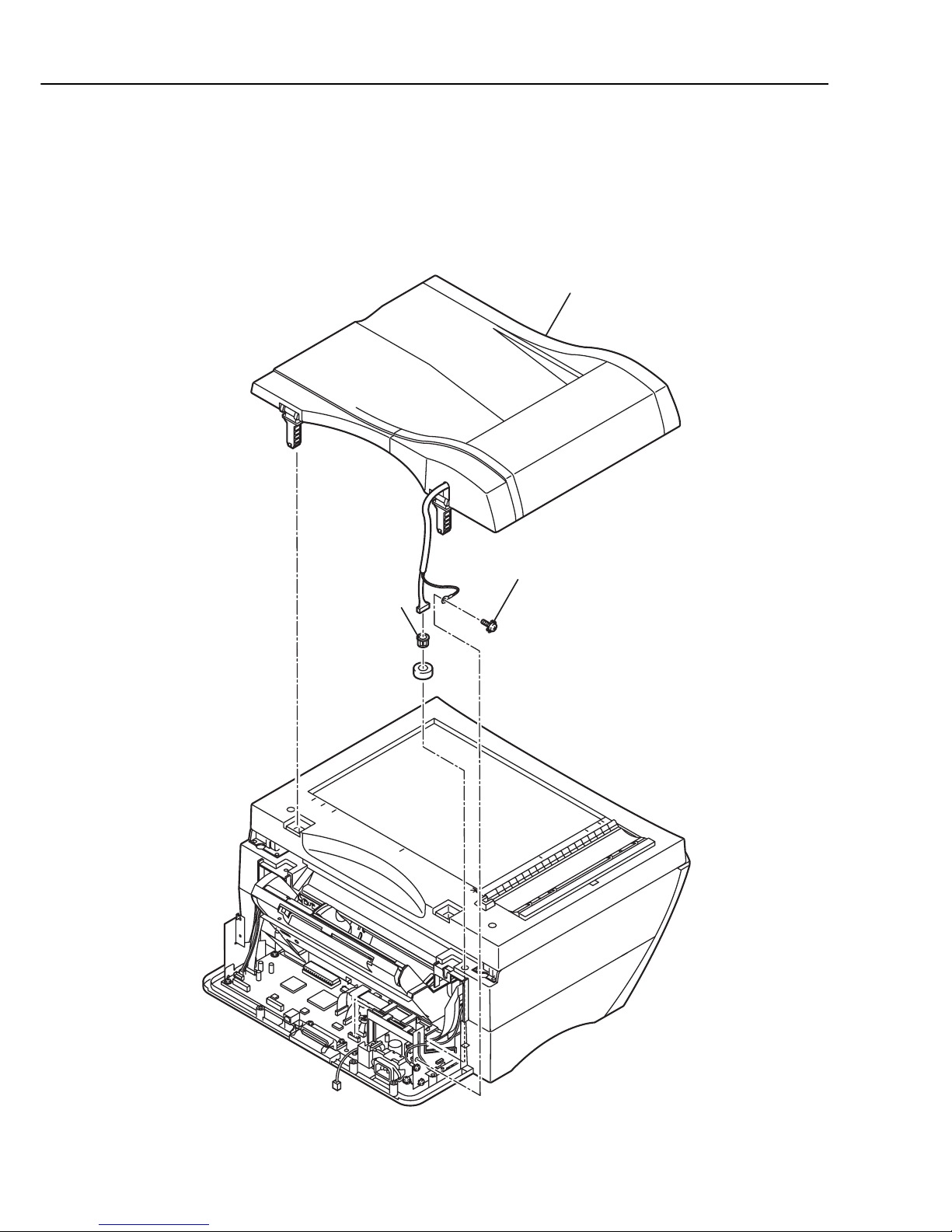
FIGURE 4 SmartBase MPC600F / imageCLASS MPC600F
DOCUMENT FEED ASS’Y
1
2
3
See FIGURE 11
for disassembly
2-8
SmartBase MPC600F/MPC400 imageCLASS MPC600F/MPC400
2.PARTS LAYOUT & PARTS LIST
FIGURE
&
KEY No.
PART No.
R
A
N
K
Q
T
Y
DESCRIPTION REMARKS
4- 1 WT2-5746-000 1 GROMMET
2 XB2-7300-607 1 SCREW, M3X6
3 NPN 1 DOCUMENT FEED ASS’Y
2-9
SmartBase MPC600F/MPC400 imageCLASS MPC600F/MPC400
2.PARTS LAYOUT & PARTS LIST
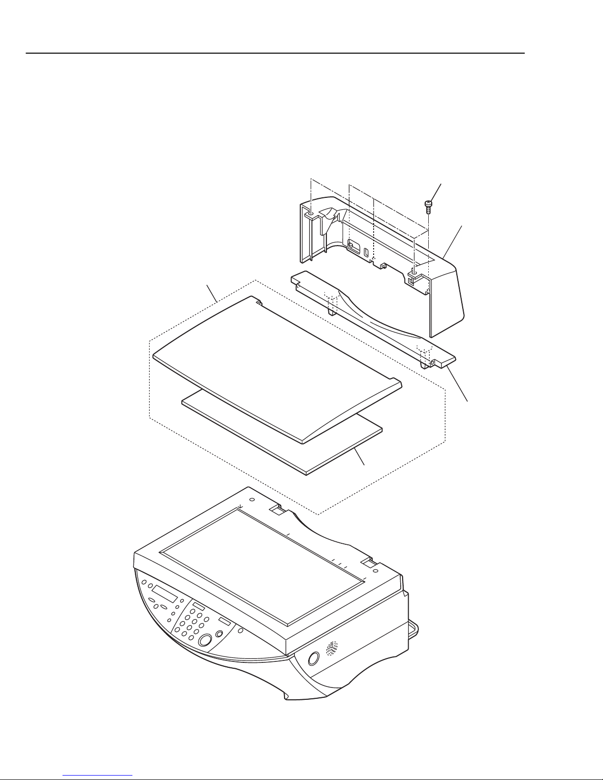
FIGURE 5 SmartBase MPC400 / imageCLASS MPC400
REAR COVER, PRESSURE PLATE
1
5
2
3
4

2-10
SmartBase MPC600F/MPC400 imageCLASS MPC600F/MPC400
2.PARTS LAYOUT & PARTS LIST
FIGURE
&
KEY No.
PART No.
R
A
N
K
Q
T
Y
DESCRIPTION REMARKS
5- 1 HC1-0013-000 1 COVER, REAR
2 HC1-0061-000 N 1 FRAME, PERSSUER PLATE
3 HC1-0063-000 1 SHEET, DOCUMENT, PRESSURE
4 HL1-0005-000 1 PRESSURE PLATE ASS’Y
5 XB4-7300-807 5 SCREW, TAP TIGHT, BINDING HEAD
2-11
SmartBase MPC600F/MPC400 imageCLASS MPC600F/MPC400
2.PARTS LAYOUT & PARTS LIST
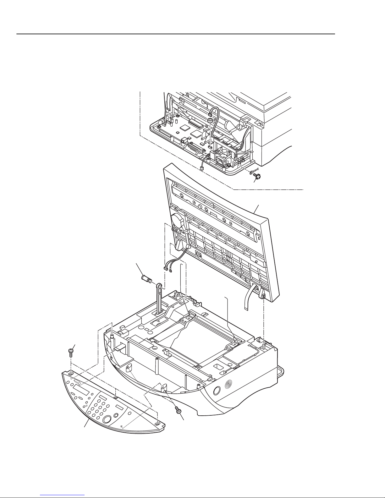
FIGURE 6
FLAT BED ASS’Y, OPERATION PANEL UNIT
1
3
5
2
4
4
See FIGURE 1
5
for disassemb
ly
 Loading...