

Page 1
1
2
BIE-7311-000
ENGLISH
© CANON INC. 2021 Printed in Japan
This
"Installation Guide
Please be sure to read the "Safety Precautions" section for correct use. After
reading this
accessible location for future reference
•
The cameras described in this document may include models not
available in your country and
•
HDMI is a trademark or registered trademark of HDMI Licensing
Administrator
•
All other company or product names used in this document are
trademarks or registered trademarks of their respective holders
•
The contents of this document are subject to change without any prior
.
notice
The latest user manuals and software, etc. for this product can be
downloaded from the following website
camera settings and operations
camera to ensure correct use
List of Downloadable Files
User Manuals Software
•
Settings Guide
•
Remote Camera Control
Application User Manual
Check Included Items
Camera
Ceiling Plate
Safety Wire 3 m
Wire Stopper (for safety wire
Camera-to-Mount Safety Wire 10 cm (3.94 in
M3 Screw x 6 (for camera mounting, camera-to-mount safety wire, and wire
stopper x 4
Compact Power Adapter
Power Cable
IR Remote Controller
Size AAA Battery x 2
Printed Materials
Symbols used in this manual
with this icon are not included with the camera
the user
)
Parts indicated in the
.
REMOTE CAMERA
Installation Guide
Important Information
/
Important Information" is comprised
"
Installation Guide/Important Information
,
Inc. in the United States and other countries
.
.
This camera is for indoor use only
/
or region
.
Read them carefully before using the
.
.
The user manuals explain the
global.canon/ncsp
•
Camera Search Tool
•
Remote Camera Control
Application
Firmware
(
only provided at time of update
(9.
.)
8 ft
)
(
for IR remote controller
"
Installation Guide/Important Information
.)
)
,
and should be prepared by
of pages [1
,
keep it in a readily
"
/
.
2] and [2/2]
.
"
[2
.
)
/
2]
Safety Precautions
Warning
Do not install in the following places:
•
Places in direct sunlight, near heat-generating objects, or locations subject
to high temperatures
•
Places near fire sources or flammable solvents (alcohol, thinner, fuel, etc
•
Humid or dusty places
•
Places subject to oily smoke or steam
•
Confined or enclosed places
Failure to do so may result in fire or electric shock
Notes on installation at high places
.
•
For installation or inspection of this camera, consult the dealer where you
purchased the product
•
Install the camera in a way that ensures sufficient holding strength
according to the mounting place such as the wall
sure that the mounting place can sufficiently support the total weight
including the mounting parts and reinforce it if necessary
•
Prepare fixing screws suitable for the location and type of surface the
camera is to be installed
•
Periodically check the mounting brackets and screws for rust and
loosening
•
Do not install in unstable places, places subject to significant vibration or
impact
•
Be sure to attach the safety wire when installing the camera
•
Use the included ceiling plate to install the camera. Do not install it with
only the tripod screws
Failure to do so may result in the camera falling or other accidents
General notes on the camera
•
If any defective conditions such as smoke, strange sounds, heat, strange
odors
stop using the camera
cable for PoE
compact power adapter near the power outlet and avoid placing objects
around the power plug so that the power can be turned off immediately in
the event of an emergency
•
Do not touch the camera or the connecting cables during a thunderstorm
•
Do not disassemble or modify the camera
•
Do not scratch, pull, or forcefully bend the cables, or put a load on their
connections
•
Do not spray the camera with water, or otherwise make it wet
•
Do not touch the camera, the compact power adapter, cable connectors,
power plugs
•
Do not allow water, metal or other foreign objects to enter the camera
•
Do not use flammable sprays near the camera
•
Do not leave the compact power adapter (or the LAN cable for PoE+
power supply
•
Do not use flammable solvents such as alcohol, paint thinner or benzine
when cleaning the camera
•
Do not block the air intake or air exit vents
Failure to do so may result in fire or electric shock
Notes on Power Supply
•
Use only the included compact power adapter when using an AC adapter
•
The included compact power adapter and power cable are for this
product only
•
Do not place heavy objects on the power cable (or the LAN cable for PoE+
power supply
•
Do not allow metal pins or debris to touch the power plug or terminals
•
Wipe any dust off of the power plug. Also, if the connection is made to the
power outlet in a dusty area
•
Make sure the power plug (or the LAN cable for PoE+ power supply) is
seated all the way
•
Do not use a damaged power plug or a loose power outlet, or use it in a
manner that exceeds the rating of the wiring device such as connecting
multiple plugs to an outlet
Failure to do so may result in fire or electric shock
Notes on batteries
•
Do not put batteries in the fire, or do not heat, short circuit or disassemble
them
•
Do not charge the included batteries
•
Do not use batteries other than those specified
Failure to do so may result in fire or electric shock
Do not use the product at:
•
Places where the use is prohibited, such as in hospitals and on airplanes
•
Places within reach of babies and toddlers
.
,
or places subject to salt damage or corrosive gas
,
damage or cracks on the external case are discovered, immediately
+
.
,
or power outlets with wet hands
)
.
They cannot be used for other devices
)
.
Failure to follow the instructions may
result in death or serious injury
.
.
.
.
.
.
,
unplug the power cable from the outlet (or the LAN
power supply), and contact your nearest dealer. Place the
.
connected when the camera is not in use for long periods
.
or pull, forcibly bend, scratch or modify it
,
take measures to prevent tracking
,
and do not use it when the insertion is insufficient
.
.
.
,
ceiling, etc. Also, make
.
.
.
.
.
.
.
.
.
.
.
.
.
.
Use at such places can cause equipment to malfunction due to
radio waves and lead to accidents
.
injuries
.
Caution
Failure to follow the instructions may
result in injuries or property damages
,
or cause electric shock and
.
Notes on installation
•
.).
Installation must be carried out safely and securely in accordance with the
relevant regulations for technical standards of electrical installation
Failure to do so may result in accidents
.
.
Notes on installation
•
Take care not to damage wiring or piping
Failure to do so may result in damage to surrounding items
.
.
General notes on the camera
•
Do not touch the edges of metal parts with bare hands
•
Be careful not to get your fingers caught when installing
Failure to do so may result in injuries
.
.
.
Notes on batteries
•
Remove the batteries when they have been used up or will not be used for
a long time
•
When replacing the batteries, replace both batteries at the same time.
Also
•
Make sure + and - of the battery are oriented correctly
•
.
If any liquid from inside the battery gets on your body due to leakage,
rinse it off thoroughly with water
Failure to do so may result in injuries and malfunctions
.
•
Do not install the camera in places where radiation, X-rays, strong radio
waves or strong magnetism are generated
audio disturbance
•
We recommend the installation of a lightning arrester (a surge protection
device
•
.
.
.
.
Take measures to remove static electricity before performing any
procedures
•
Do not connect the PoE cable to the RS-422 terminal
•
Do not connect the compact power adapter to a transformer
•
If there is condensation, please wait to power on, until the condensation
dissipates
•
Do not hold the device by the camera head
•
Do not turn the camera rotator by hand
•
After turning off the power, do not turn the power on again for at least
five seconds
•
Do not point the camera at strong light sources (such as the sun on a
clear day or strong artificial light sources
the image sensor could be damaged
•
Do not carry the camera on a tripod
.
Precautions for Use (Disclaimer
Compliance with Applicable Laws/intellectual Property Rights:
.
.
.
that your use of this product may subject you to certain laws
regulations
property and publicity laws
any resulting recordings or footage complies with applicable laws
regulations
Canon Inc. and its affiliates shall have absolutely no liability with respect
to any claims made by third parties that your use of this product does not
comply with applicable laws
brought against you by third parties alleging non
or otherwise violates any third party
or proprietary rights as a result of your use of the product
responsible to you for any liability whatsoever resulting from your use
installation of this product
Limited Warranty:
about the limited warranty that pertains to your product
.
.
,
do not use different types of batteries together
.
.
.
.
Important
.
,
noise, or malfunctions
)
as a measure against failures caused by lightning strikes
.
.
.
,
including but not limited to, privacy, wiretapping and intellectual
.
Please check the in
.
Please be sure your use of this product and/or
,
rules and regulations and any resulting claims
'
s intellectual property, personal, privacy
,
and/or any loss of any recordings or footage
-
It may cause video and
.
.
.
.
).
Internal components such as
.
.
Please note
,
rules and
-
compliance with such laws,
.
We are also not
box materials for more information
.
.
.
,
rules and
,
and/or
.
)
Installation: This product should NOT be installed outdoors. You are solely
responsible for the proper installation of this product
,
Canon Inc. and its affiliates shall have absolutely no liability to you
by law
with respect to any damages or liabilities associated with the improper use of
or the installation of this product
or any third parties as a result of any such improper use or installation of this
,
whether or not the installation of this product was by you, or by any
product
third party
Privacy:
•
Do not install this product in areas where people have a reasonable
•
•
Making audio recordings is heavily regulated and can vary significantly
OTHER IMPORTANT INFORMATION: Please see other important information
pertaining to the use of this product by reading our Settings Guide
can also be found at global
.
expectation of privacy
,
locker rooms and rest room facilities
rooms
Some jurisdictions require signage disclosing the existence of camera
equipment. Please check your own area's laws for requirements.
.
Please check laws in your jurisdiction before making any audio
by area
recordings
.
,
or for any personal injuries sustained by you
,
including but not limited to, bedrooms, dressing
.
canon/ncsp, prior to using this product
.
To the extent permitted
.
,
which
.
About lamp
Lamp Lamp status Status
STATUS lamp
POWER lamp
Tally lamp
Orange light ONStandby
Orange light
BLINKING
Orange light
ON
Green light
ON
Green light
BLINKING
Red light ON Distributing data
Green light
ON
Power shortage
PT position error
Firmware being updated
Device failure
Standby
Power on
(
Initializing
IR remote control signal received
(
Blinks twice
Moving to or returning from standby
Device failure
Preparing to distribute data
Starting and restarting
)
)
Before using the camera
Initial settings
Be sure to make the initial settings before use. If the initial settings are not
,
the video cannot be outputted. Refer to the "Settings Guide" for
made
.
details
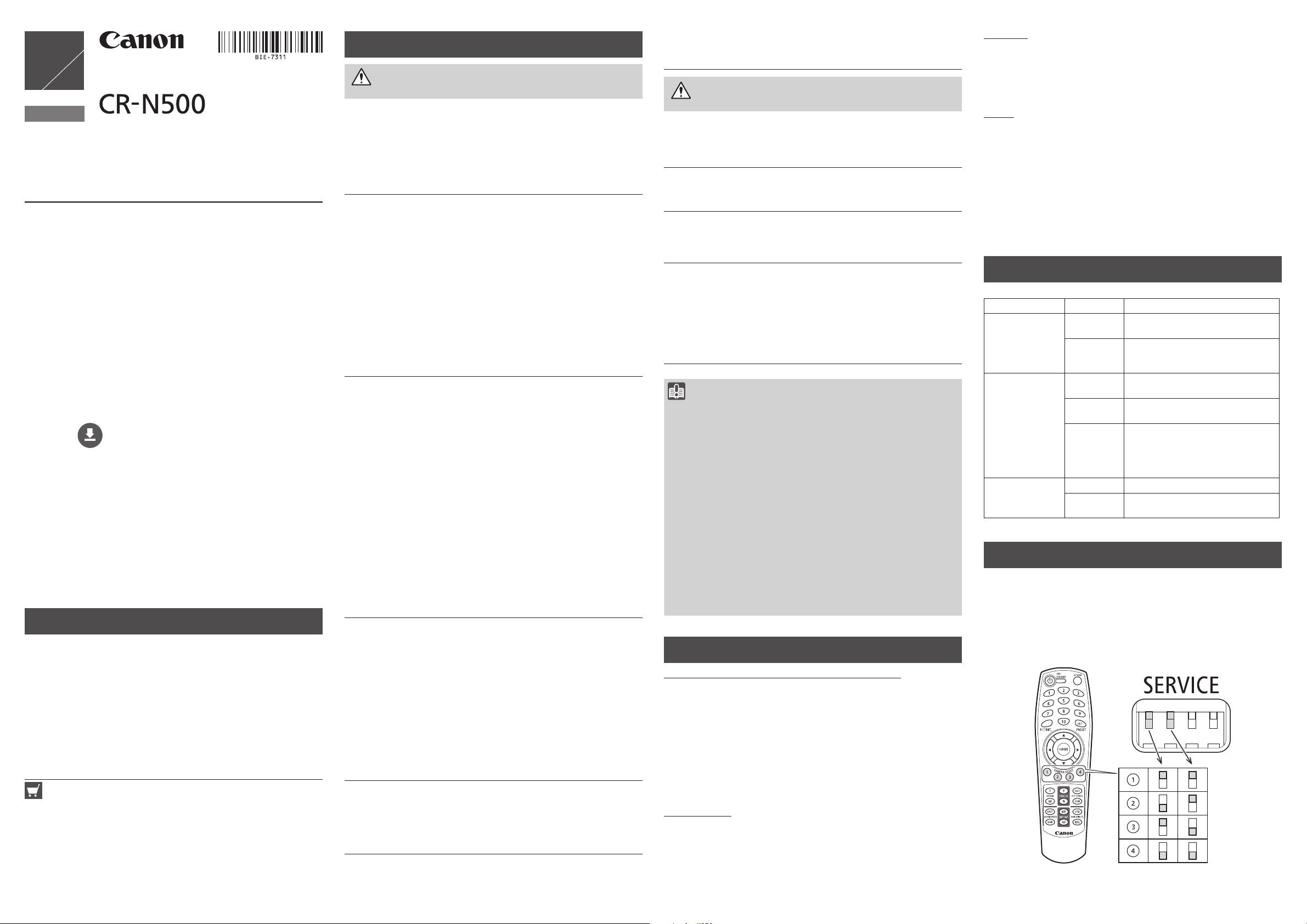
SERVICE switch settings
Set the camera number to be operated by the IR remote controller
Switches should be set before turning on the power
.
.
,
Page 2
Notes for When and After
4.5 – 5.5 mm (0.18 – 0.22 in.)
1/4-20UNC
1 2 3 4 5 6 7 8
10 91112131415
Installing the Camera
When Installing the Camera
Installation at high places
Caution
Request a professional installer for all
.
installation work
camera yourself
Never try to install the
.
Doing so may result in
unforeseen accidents such as dropping
the camera or electric shock
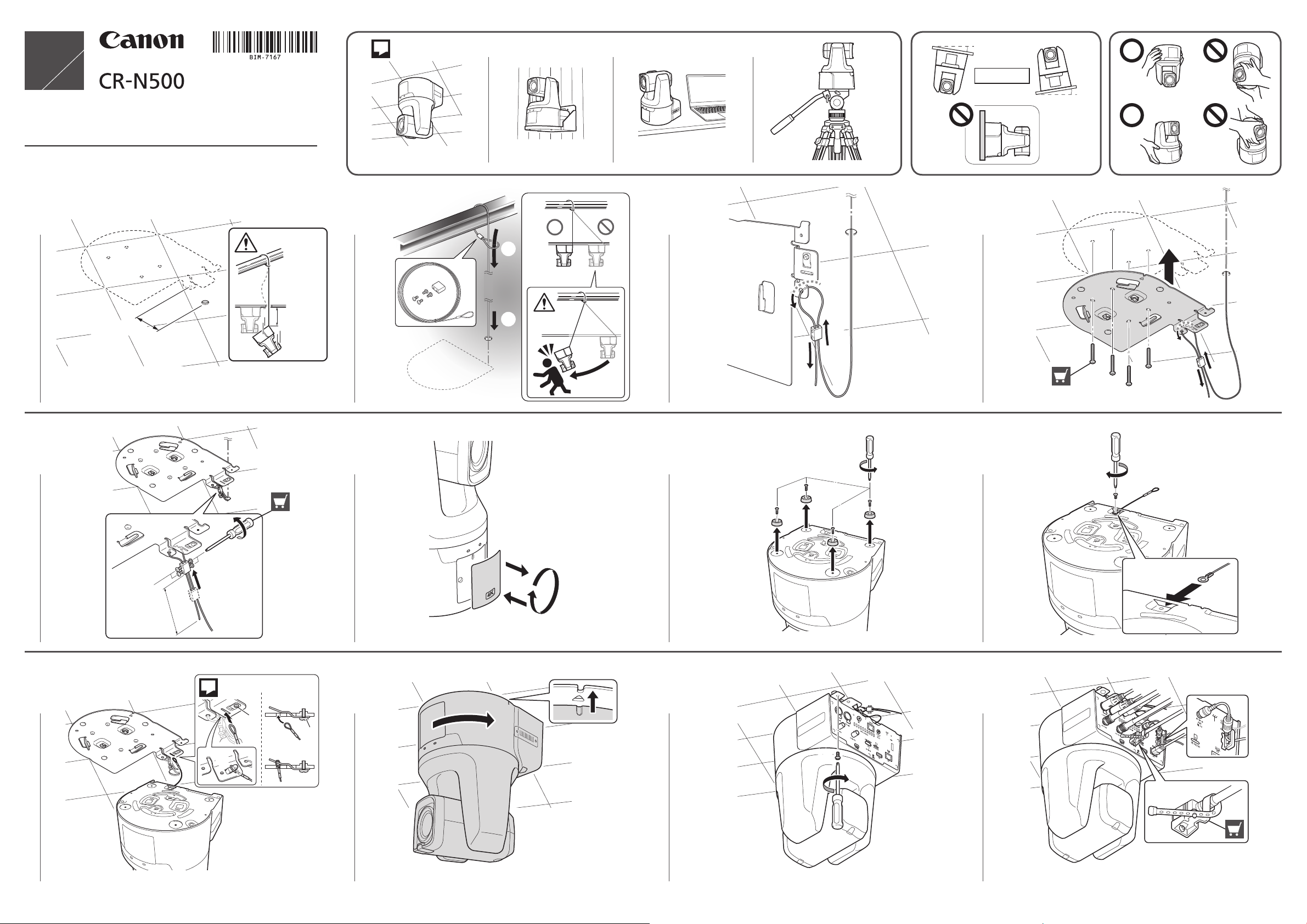
When installing the camera at a high place, use the ceiling plate to fix the
.
Fix the ceiling plate tightly with four M4 screws (pan head, binding
camera
,
.).
etc
head
When working with the camera upside down
it from wobbling in order to attach or remove the rubber feet or the camera
to-mount safety wire. Keep the four rubber feet and four screws that have
been removed for reuse in case of a change in the installation
Ceiling mount
The camera is hung upside down from the ceiling or other location using the
ceiling plate
The procedure provided in the
explains this installation method. The weight of the camera (body only) is
Approx
material to ensure the sufficient holding strength to support the total weight
including the camera and the mounting parts
Standing mount
The camera is fixed to a high place using the ceiling plate
Follow the same procedure as for the ceiling mount, except for the direction
of the camera and logo plate inversion
Tripod mount
Attach the tripod by fixing two screws to the two screw holes for tripod
Use 1/4-20UNC screws and tighten them securely, and set the tripod on a
flat surface with no steps
Also refer to the instructions in the
/2],
[2
Desktop
Install the camera on a stable, horizontal surface such as a table
Also refer to the instructions in the
/2],
[2
.
. 4.
1 kg (9.04 lb
if necessary
if necessary
,
support the camera to prevent
/
"Installation Guide
.).
Reinforce the ceiling depending on its structure and
.
.
Important Information"
,
and install
"Installation Guide
.
"Installation Guide
.
.
.
[2
.
.
.
/
Important Information"
/
Important Information"
.
/
-
2]
Connecting the Camera
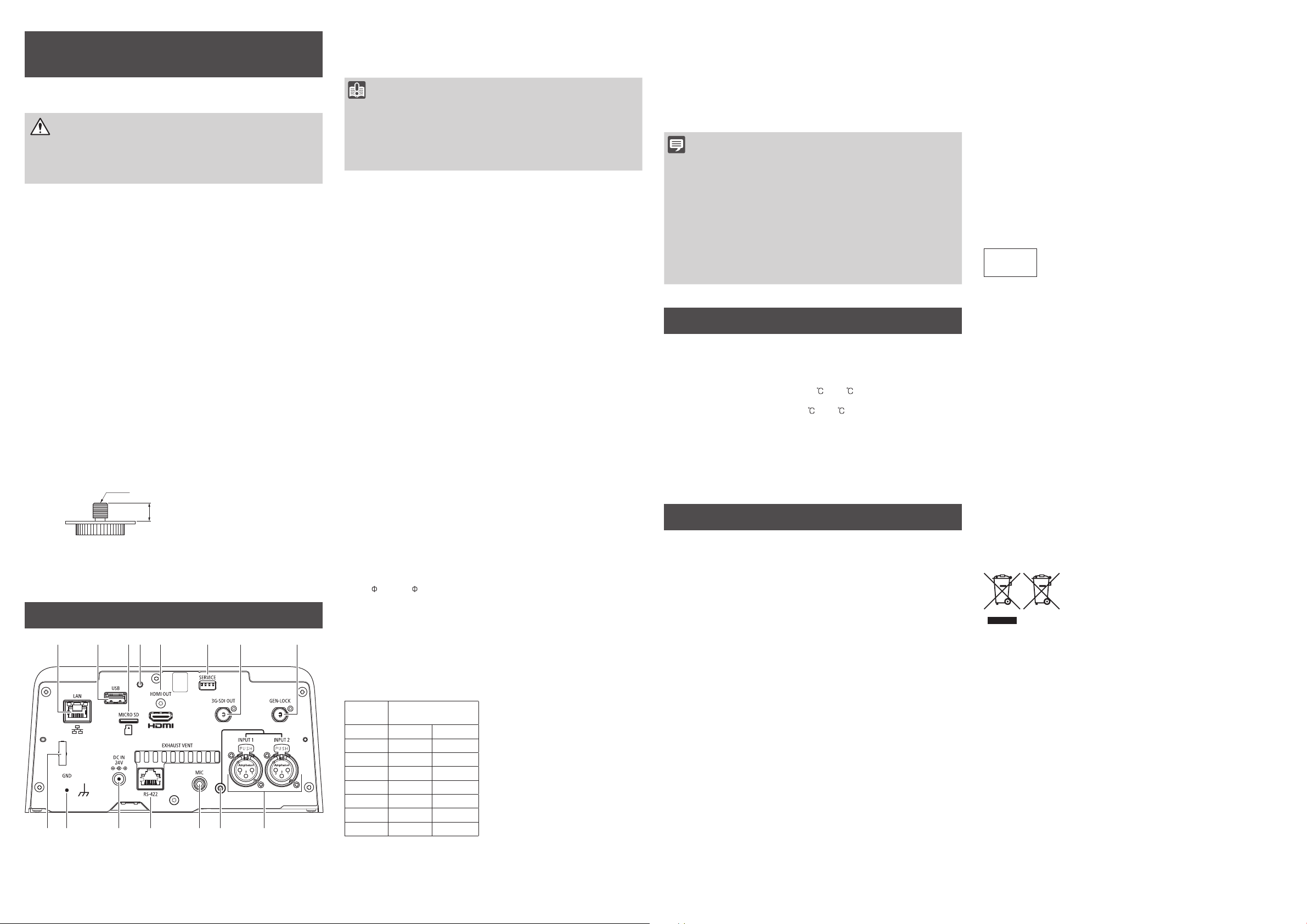
1. LAN terminal
This terminal is for a network connection (RJ-45 connector
The built-in PoE+ (Power over Ethernet+) function allows the camera to be
).
+
powered by a PoE
.
cable
HUB that complies with IEEE802.3at Type 2 via a LAN
Use a category 5e or higher STP (shielded type) LAN cable, up to 100 m (328 ft.)
.
in length
Important
•
Some PoE+ HUBs can limit the power for each port, but applying limits
may interfere with performance
•
Some PoE+ HUBs have limits for the total power consumption for
the ports
are in use
corresponding PoE
,
which can interfere with performance when multiple ports
.
For more information, check the instruction guide for the
+
HUB
.
In this case, do not limit the power
.
2. USB terminal
For future expansion
.
3. Memory card slot
future expansion
For
.
4. RESET switch
Initialize the camera settings to the factory defaults. Refer to the "Settings
Guide" for details
.
5. HDMI OUT terminal
Terminal for HDMI output
.
6. SERVICE switch
Set the camera number operated by the IR remote controller
(
Refer to "Before using the camera" > "SERVICE switch settings"
.
7. 3G-SDI OUT terminal
Terminal for 3G-SDI output (BNC
).
8. GEN-LOCK terminal
Terminal for the synchronization signal input (BNC) to synchronize the videos
from the camera and external devices
If the reference signal is unstable, external synchronization is not possible
Subcarriers do not synchronize
9. INPUT1/INPUT2 terminal
XLR terminals for audio input. It can be used for microphone/line input
•
Microphone input: Input impedance 600 Ω ±10%
Microphone power
Bias resistance: 6
•
Line input: Input impedance 10k Ω ±10%
(
Phantom power): 48 V ±1 V
.8 Ω ±
1%
.
.
10. LED for phantom power supply
It is lit in blue when the phantom power is supplied
11. MIC terminal
Stereo 3.5 mm
microphone
•
Microphone input: Input impedance 1.5k Ω or higher
Microphone power: 2
Bias resistance: 2
•
Line input: Input impedance 1.5 k Ω or higher
(
0.14 in.) terminal for audio input. It can be used for
/
line input
.
.
4 V ±0.2 V
.
2 k Ω ±5%
.
12. RS-422 terminal
Serial terminal (RJ-45 connector) for RS-422
Connect the GNDs on both ends to stabilize the voltage level of the signal
Use category 5e or higher STP cables
Pin
number
1 TX
2 TX
3 RX
4 GND
5 GND
6 RX
7 NC
8 NC
+
-
+
Function
Output
Output
Input
–
–
Input
–
–
(-)
(+)
(-)
(+)
.
.
13. DC IN 24V terminal
er supply terminal for the compact power adapter
Pow
.
14. GND terminal
Ground terminal of the camera
It is used to install a lightning arrester (surge protection devices
.
).
15. Cable clamp
Cable clamp to prevent cord disconnection
Pass the compact power supply cord through the clamp to prevent the cord
.
from coming off
Note
•
The camera is not equipped with a power switch. To turn the camera
on and off
connected to the "13
to the "1
When both the PoE
connected
.
,
insert and remove the cable of the compact power adapter
.
LAN terminal", which supplies power.
,
the compact power adapter takes priority. If the compact
.
DC IN 24V terminal" or the PoE+ HUB connected
+
HUB and the compact power adapter are
power adapter is disconnected while both adapters are connected
power to the camera will be interrupted
restored by disconnecting and reconnecting the LAN cable
•
The audio input terminals ("9. INPUT1/INPUT2 terminal", "11. MIC
terminal"
)
and microphones should be set using the Settings Page. Refer
to the "Settings Guide" for details
.
.
In this case, power can be
.
,
.
This device complies with Part 15 of FCC Rules and ISED's applicable
(s).
licenceexempt RSS standard
Operation is subject to the following two
conditions:
(1)
this device may not cause interference, and
(2)
this device must accept anyinterference, including interference that may
cause undesired operation of this device
.
This equipment complies with FCC/ISED radiation exposure limits set
forth for an uncontrolled environment and meets the FCC radio frequency
(RF)
Exposure Guidelines and RSS-102 of the ISED radio frequency (RF)
Exposure rules
the radiator at least 20 cm or more away from person
.
This equipment should be installed and operated keeping
'
s body
.
This transmitter must not be co-located or operated in conjunction with any
other antenna or transmitter
.
FDA regulation
This product has not been evaluated by the Food and Drug Administration
(
FDA) for use as a medical device. When incorporated into a system with
medical applications
your legal advisor to determine whether FDA regulations apply
Complies with
IMDA Standards
DB00671
,
FDA regulations may apply. Therefore, please consult
.
European Union regulatory notices:
,
Remote Camera
Specifications
.)
.
.
Please refer to the 'Specifications' in the 'Appendix' of the "Settings Guide"
for specifications not listed below
Pan operation range: Horizontal ±170
Tilt operation range: Vertical -30° – +90
.
°
°
Operating Environment: Temperature: 0 – +40 (+32°F – +104°F)
Humidity: 10%
–
90% (without condensation
)
Storage Environment: Temperature: 0 – +40 (+32°F – +104°F)
Humidity: 10%
–
90% (without condensation
)
Power Consumption: PoE+ Input: Approx. 19.6 W* max. (body only)
.
DC Input: Approx
*
Dimensions
(
W x H x D): Approx. 200 x 269 x 208 mm (7.87 x 10.59 x 8.19 in.)
Class 4 (25.5 W required) for power supply devices
(
excluding protrusions
Weight: Approx. 4.1 kg (9.04 lb.) (body only
18.6 W max. (body only)
)
)
Warning
This is a class A product
radio interference in which case the user may be required to take adequate
measures
Use of shielded network cable is required to comply with Class A limits in
EN55032
Wireless LAN Specifications
Frequency range: 2
Maximum output power: 9
For EU
,
Canon Inc., declares that the radio equipment type CR-N500 is in
Hereby
compliance with Directive 2014
conformity is available at the following internet address:
//
www.canon-europe.com/ce-documentation
http:
For UK
,
Canon Inc., declares that the radio equipment type CR-N500 is
Hereby
in compliance with the relevant statutory requirements
Country Regulations
About wireless communication
Regarding countries and regions where radio communication functions are
acceptable
Since the utilization of the radio communication functions can be legally
restricted by a country or region
country or the region where the product is purchased
,
it may not be possible to utilize out of the
.
Canon shall not be
declaration of conformity is available at the following internet address:
//
www.canon-europe.com/ce-documentation
https:
Only for European Union and EEA (Norway, Iceland and Liechtenstein
These symbols indicate that this product is not to be disposed of with your
liable for any incidents that may incur as a result of the utilization of the
radio communication functions in any country or region other than where the
product is purchased
FCC NOTICE
Remote Camera
This device complies with Part 15 of the FCC Rules
to the following two conditions:
,
.
interference
including interference that may cause undesired operation
and (2) this device must accept any interference received,
Note: This equipment has been tested and found to comply with the limits for
a Class A digital device
These limits are designed to provide reasonable protection against harmful
interference when the equipment is operated in a commercial environment
This equipment generates
,
if not installed and used in accordance with the user manual, may cause
and
harmful interference to radio communications
in a residential area is likely to cause harmful interference in which case the
user will be required to correct the interference at his own expense
Do not make any changes or modifications to the equipment unless
otherwise specified in the manual
,
be made
you could be required to stop operation of the equipment
Use of shielded cable is required to comply with class A limits in Subpart B
of Part 15 of FCC Rules
Model: CR-N500 (including WLAN Module Model ES202, FCC ID: AZD239 /
-
)
IC: 498J
239
.
,
Model Name: CR-N500
(1)
This device may not cause harmful
,
pursuant to Part 15 of the FCC Rules
,
uses, and can radiate radio frequency energy
.
If such changes or modifications should
.
.
Operation is subject
.
.
.
Operation of this equipment
.
.
Cd = Cadmium
a concentration above an applicable threshold specified in the Battery
Directive
This product should be handed over to a designated collection point, e.g.,
on an authorized one
to an authorized collection site for recycling waste electrical and electronic
equipment
this type of waste could have a possible impact on the environment and
human health due to potentially hazardous substances that are generally
associated with EEE
.
will contribute to the effective usage of natural resources
For more information about the recycling of this product
local city office
disposal service or visit www
CANON INC
30-2, Shimomaruko 3-chome, Ohta-ku, Tokyo 146-8501, Japan
Canon U
One Canon Park, Melville, NY 11747, U.S.A
Tel No. 1-800-OK-CANON (1-800-652-2666
CANON EUROPA N.V
Bovenkerkerweg 59, 1185 XB Amstelveen, The Netherlands
Model Name: CR-N500
.
In a domestic environment this product may cause
.
.
,
401 MHz – 2,473 MHz
.
48 dBm
/53/EU.
The full text of the EU declaration of
.
The full text of the
/
,
household waste
(
2012/19/EU), the Battery Directive (2006/66/EC) and/or
according to the WEEE Directive
national legislation implementing those Directives
If a chemical symbol is printed beneath the symbol
,
shown above
this indicates that a heavy metal
,
Pb = Lead) is present in this battery or accumulator at
.
-
for-one basis when you buy a new similar product or
(
EEE) and batteries and accumulators. Improper handling of
.
Your cooperation in the correct disposal of this product
,
waste authority, approved scheme or your household waste
.
.S.A.
.
Inc
.
in accordance with the Battery Directive,
(
Hg = Mercury,
.
,
please contact your
.
canon-europe.com/sustainability/approach
.
)
)
.
/.
Page 3
2
2
BIM-7167-000
1
θ
θ ≦ ± 5°
θ
© CANON INC.
1
5
2021
Printed in Japan
L < 100 mm
L < 100 mm
2
6
3
4
7 8
9
L > 300 mm
2
0.6 N·m
M3 x 4
10
180°
11
M3
12
M3M3
Page 4
5
16
Unit: mm
1/4-20UNC
58
R103
200
1/4-20UNC
58
200
1
6
12
Serial_ _ _ _ _ _ _ _ _ _ _ _ _ _ _ _ _
MAC_ _ _ _ _ _ _ _ _ _ _ _ _ _ _ _ _ _
10 10
13
10
189
46
Φ189
10
11
4
2
3
2
7
4
8
14
15
83.5
2
Φ200
228
9
JA
カメラヘッド /
1.
5.
タリーランプ
*
ンプ
12
. ロゴプレート /
9
/
. 定格銘版 /
* 詳細は「使用説明書 重要事項・設置編
EN
. 赤外線リモコン受光部 /
2
*
. レンズ /
6
/
. 三脚用ネジ穴 /
13
. ゴム脚 /
10
.
7
STATUS
11
. 排気口 /
14
. ベース /
3
*
ランプ
. 取付用板金固定ネジ穴 /
15
/2]」参 照
1
[
. 吸気口 /
4
.
8
/
POWER
. 背面パネル
ラ
*
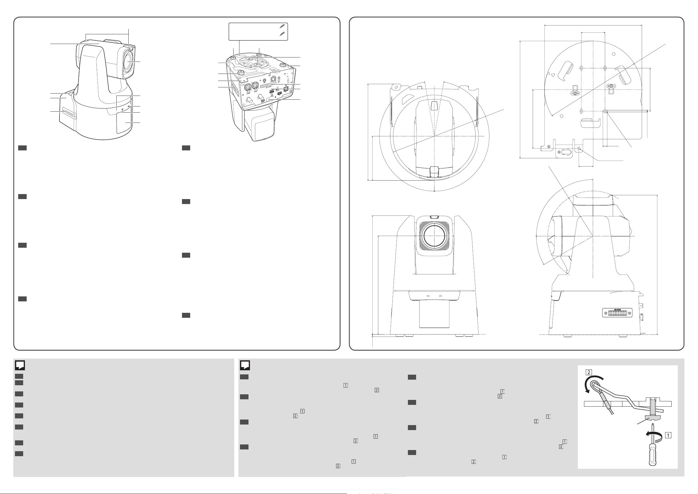
1. Camera head / 2. IR remote control receiver / 3. Base / 4. Air intake vent /
5. Tally lamp
*
/ 6. Lens / 7. STATUS indicator* / 8. POWER indicator* / 9. Logo
plate / 10. Rubber feet / 11. Screw hole for fixing ceiling plate / 12. Rating
label / 13. Screw hole for tripod / 14. Air exit vent / 15. Rear panel
*
Refer to the "Installation Guide/Important Information" [1/2] for details.
DE
*
1. Kamerakopf / 2. Empfänger für IR-Fernbedienung / 3. Sockel /
4. Lufteinlassöffnung / 5. Kamerakontrolllampe* / 6. Objektiv /
7. STATUS-Anzeige* / 8. STROM-Anzeige* / 9. Logoschild / 10. Gummifüße /
11. Schraubenloch zur Befestigung der Deckenplatte / 12. Typenschild /
13. Schraubenloch für Stativ / 14. Luftauslassöffnung / 15. Rückwärtiges Bedienfeld
*
Für weitere Informationen siehe „Installationshandbuch/Wichtige Informationen“ [1/2].
ES
*
1. Cabezal de la cámara / 2. Receptor de control remoto IR / 3. Base / 4. Entrada
de ventilación / 5. Luz de recuento
*
/ 6. Objetivo / 7. Indicador de ESTADO* /
8. Indicador de ENCENDIDO* / 9. Plancha de logotipo / 10. Patas de goma /
11. Orificio para atornillar la plancha de techo / 12. Etiqueta de calificación /
13. Orificio para atornillar el trípode / 14. Salida de ventilación / 15. Panel trasero
*
* Consulte la "Guía de instalación/Información importante" [1/2]
para conocer más detalles.
FR
1. tête de camera / 2. Récepteur de télécommande infrarouge / 3. Base /
4. Orifice d'admission d’air / 5. Lampe tally* / 6. Objectif / 7. Indicateur d’état* /
8. Indicateur d’alimentation* / 9. Plaque de logo / 10. Pieds en caoutchouc /
11. Trou de vis pour plaque de fixation / 12. Étiquette constructeur / 13. Trou
de vis pour trépied / 14. Orifice de sortie d’air / 15. Panneau arrière
*
Consultez le « Guide d’installation/informations importantes » [1/2] pour plus de détails.
IT
*
1. Testina della telecamera / 2. Ricevitore del telecomando a infrarossi / 3. Base /
4. Presa d'aria / 5. Lampada tally* / 6. Obiettivo / 7. Indicatore di STATO* /
8. Indicatore di ALIMENTAZIONE* / 9. Piastra del logo / 10. Piedini di gomma /
11. Foro per la vite di fissaggio della piastra a soffitto / 12. Etichetta di classificazione /
13. Foro della vite per il treppiede / 14. Sfiato dell'aria / 15. Pannello posteriore
*
Per i dettagli, consultare il documento “Guida all’installazione/Informazioni importanti” [1/2].
RU
*
1. Головка камеры / 2. ИК приемник дистанционного управления / 3. Основание /
4. Впускное вентиляционное отверстие / 5. Индикатор съемки* / 6. Объектив /
7. Индикатор состояния STATUS
*
/ 8. Индикатор питания POWER* / 9. Табличка
с логотипом / 10. Резиновые ножки / 11. Отверстие под винт для крепления
потолочной пластины / 12. Табличка с техническими данными / 13. Отверстие под
винт для штатива / 14. Выпускное вентиляционное отверстие / 15. Задняя панель
*
Подробности см. в документе «Руководство по установке/Важная информация» [1/2].
ZH
*
1. 摄像机头部 / 2. 红外线遥控接收器 / 3. 底座 / 4. 进气口 / 5. 摄像指示灯* /
6. 镜头 / 7. STATUS指示灯* / 8. POWER指示灯* / 9. 标志牌 / 10. 橡胶脚垫 /
11. 吊顶板固定螺孔 / 12. 额定铭牌 / 13. 三脚架螺孔 / 14. 排气口 / 15. 后面板
*
* 有关详细信息,请参阅“安装指南/重要信息[1/2]”
218
269
5
100
223
170°
170°
114.0
30°
R103
90°
28.0
4 x 8.5
Φ5
8 x (R)
4 x 4.5
316
Unit: mm
1
設置の手順は天吊り設置で説明します。据え置き / 机上 / 三脚の設置では必要に応じて参照してください。
JA
Installation procedure is explained using the ceiling mount as an example. Refer to this section as reference if
EN
necessary, for standing mount, desktop and tripod mount.
Der Installationsvorgang wird anhand der Deckenmontage als Beispiel erläutert. Ziehen Sie diesen Abschnitt
DE
bei Bedarf zur Referenz heran– bei Standmontage, Desktop und Stativmontage.
El procedimiento de instalación se explica con el montaje en techo como ejemplo. En caso necesario, consulte
ES
esta sección como referencia para el montaje de pie, en escritorio y el montaje en trípode.
La procédure d’installation est expliquée en prenant le support de plafond pour exemple. Si nécessaire,
FR
consultez cette section à titre de référence pour le montage sur pied, sur table ou sur trépied.
Per la spiegazione della procedura di installazione sarà utilizzata come esempio l'installazione a soffitto.
IT
Consultare questa sezione, se necessario, per montaggio con staffa, montaggio su tavolo e montaggio su
treppiedi.
Процедура установки рассматривается на примере монтажа на потолке. Обращайтесь к этому разделу
RU
для справок по мере необходимости при монтаже на полу, на столе или на штативе.
使用天花板安装作为示例对安装步骤进行说明。对于直立安装、桌面和三脚架安装,必要时请参考本节。
ZH
2
スリットから設置用落下防止ワイヤーを通し ()、裏側にあるフックに引っか
JA
けます
(
)。
ワイヤーの外し方:フック固定ネジ (★) を緩め ( )、ワイヤーをフックから逃
がす方向に上下させて設置用落下防止ワイヤーを外してください
Pass the Camera-to-Mount Safety Wire through the slit
EN
hook on the rear side
How to remove the wire: Remove the Camera-to-Mount Safety Wire by loosening
the hook fixing screw (★)
release from the hook
Führen Sie das Sicherungsseil zwischen Kamera und Halterung durch den
DE
Spalt
So entfernen Sie das Seil: Entfernen Sie das Sicherungsseil zwischen Kamera
und Halterung durch Lösen der Hakenbefestigungsschraube (★)
und Abbewegen des Seils, um es vom Haken zu lösen
Pase el cable de seguridad de la cámara al montaje a través de la hendidura
ES
y átelo al gancho situado en la parte posterior
Cómo retirar el cable: Para retirar el cable de seguridad de la cámara al
montaje, afloje el tornillo para fijación del gancho (★)
arriba y hacia abajo para soltarlo del gancho
and attach it to the
.
and moving the wire upward and downward to
.
und befestigen Sie es an dem Haken auf der Rückseite
.
.
y mueva el cable hacia
.
( )。
.
und Auf-
Faites passer le fil de sécurité reliant la caméra au support dans la fente
FR
fixez-le au crochet situé à l’arrière
Pour retirer le fil: Retirez le fil de sécurité reliant la caméra au support en
desserrant la vis de fixation du crochet (★)
et vers le bas pour le dégager du crochet
Passare il cavo di sicurezza dalla telecamera al supporto di montaggio nella
IT
fessura
Come rimuovere il cavo: rimuovere il cavo di sicurezza dalla telecamera al
supporto di montaggio allentando la vite di fissaggio del gancio (★)
muovendo il cavo verso l'alto e il basso per staccare il gancio
Проведите предохранительную проволоку, соединяющую камеру с
RU
креплением, через прорезь
Порядок снятия проволоки: снимите предохранительную проволоку,
соединяющую камеру с креплением, ослабив крепежный винт крючка
и перемещая проволоку вверх и вниз, чтобы высвободить ее с крючка
将安装用安全钢丝从细缝穿过(
ZH
如何取下钢丝:通过松开挂钩固定螺丝(★) (
脱离来取下安装用安全钢丝(
e collegarlo al gancio nella parte posteriore
.
et en déplaçant le fil vers le haut
.
.
.
и прикрепите ее к крючку на задней стороне
),然后将其挂在后方的挂钩上(
),然后上下移动钢丝以从挂钩上
)。
)。
e
(★)
et
.
.
 Loading...