

Page 1

image PASS-D1/Color Network Printer Unit-D1
Installation Procedure
Module Imprimante Couleur reseau-D1 Procédure
d’Installation
Farbdruckerkarte D1 Installation
Unità D-1 Stampante di rete a colori Procedura di
installazione
PSプリントサーバユニット-D1
設置手順書
Follow the instructions herein when installing the image PASS-D1/Color Network Printer Unit-
D1 to its host machine.
Suivre les instructions suivantes pour l’installation de Module Imprimante Couleur reseau-D1.
Beachten Sie bitte bei der Installation der Farbdruckerkarte D1 in die Hosteinheit die Anleitungen.
Seguire le istruzioni qui di seguito durante l’installazione Unità D-1 Stampante di rete a colori
alla macchina host corrispondente.
接続機器にPSプリントサーバユニット-D1を取り付ける際はこの手順に従って下さい。
ENGLISH
FRANÇAIS
DEUTSCH
ITALIANO
日本語
Page 2
imagePASS-D1/Color Network Printer
Unit-D1 Installation Procedure
Follow the instructions in this booklet when installing the imagePASS-D1/Color Network Printer Unit-D1 to its
host machine.
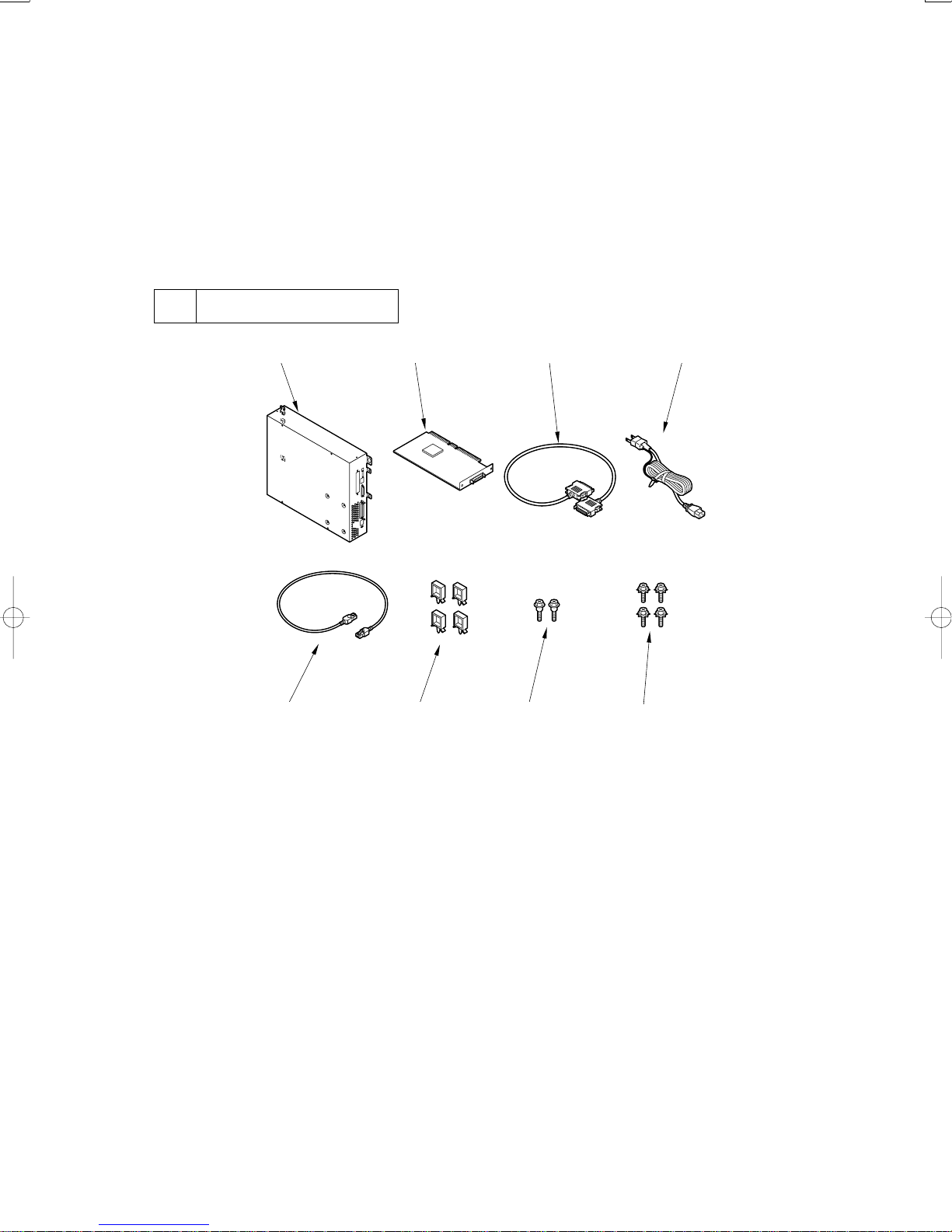
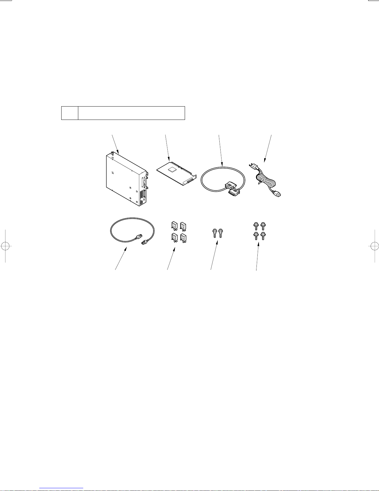
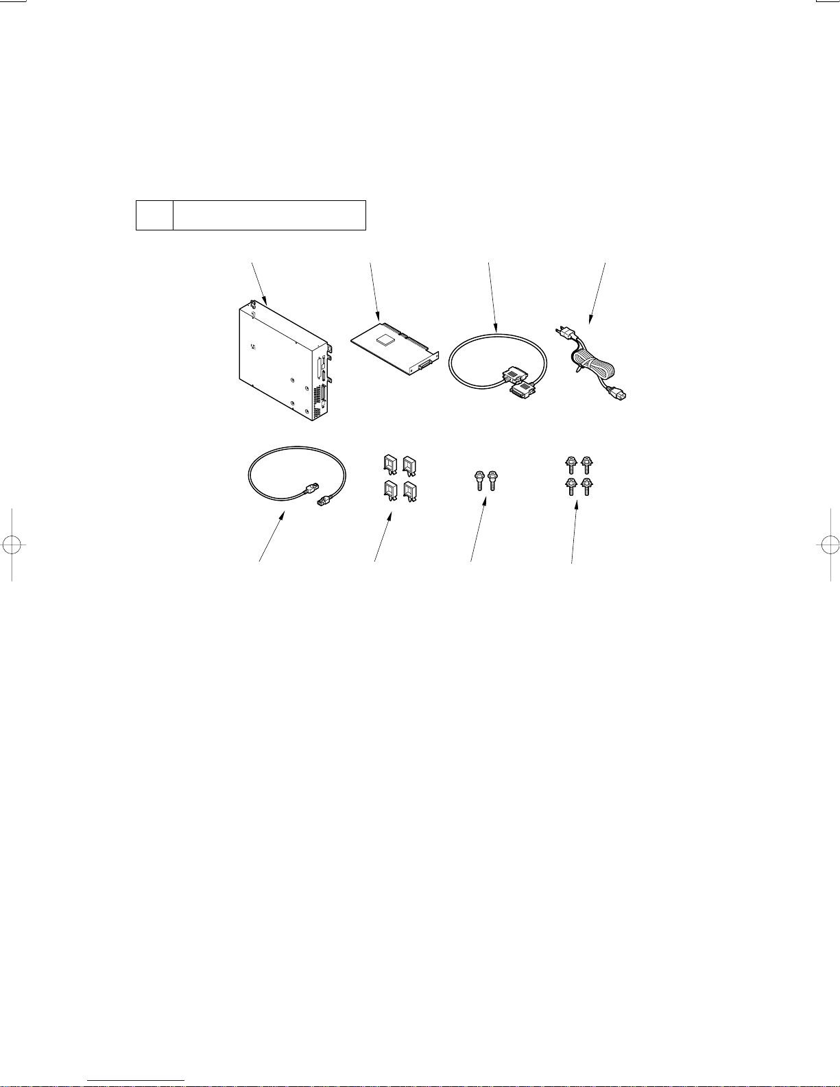
1 Checking the Contents
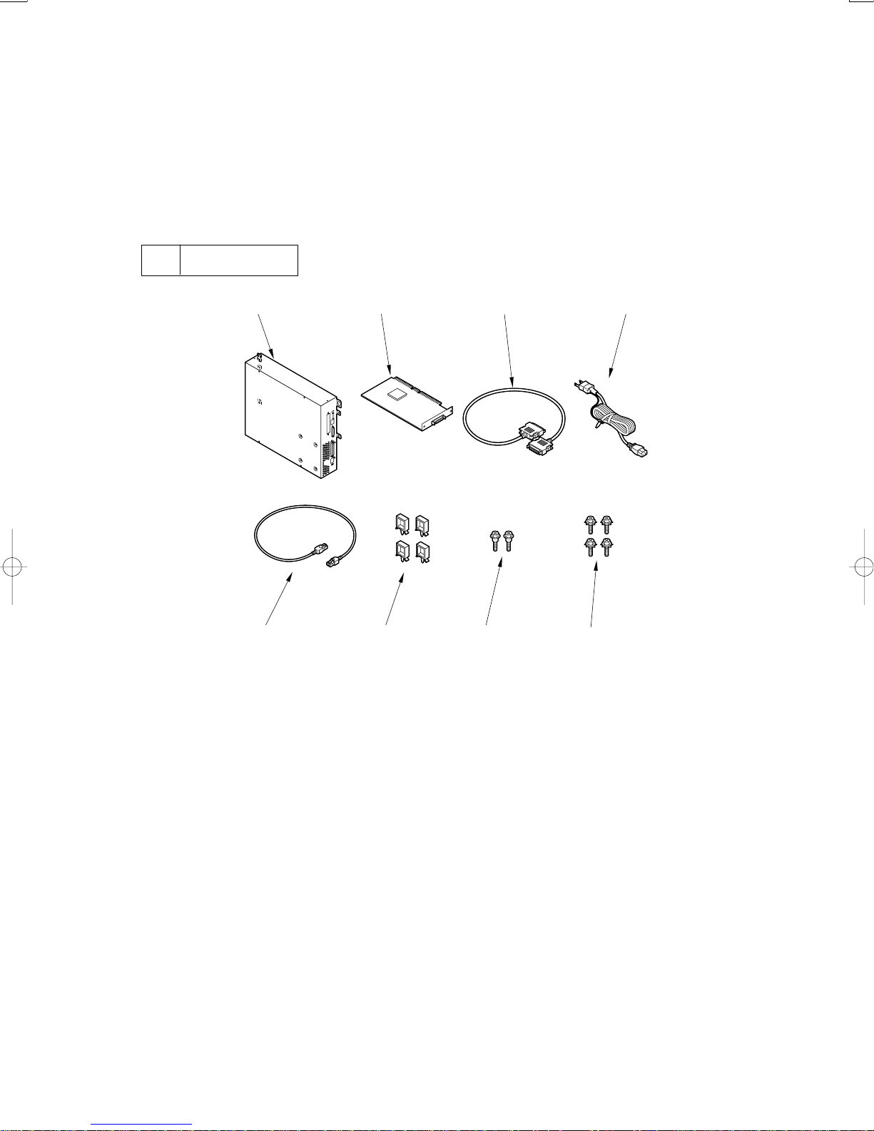
[1] [2] [3] [4]
[5] [6] [7]
[1] Unit ............................................................ 1 pc.
[2] Open I/F PCB ............................................. 1 pc.
[3] Communications cable ............................... 1 pc.
[4] Power cable ................................................. 1 pc.
[8]
Fig. 1-1
[5] Cross Ethernet cable ................................... 1 pc.
[6] Cable clamp ................................................ 4 pc.
[7] Stepped screw ............................................. 2 pc.
[8] RS tightening screw (w/ washer) ................ 4 pc.
– 2 –
Page 3
2 Installation
2.1 Before Starting the Work
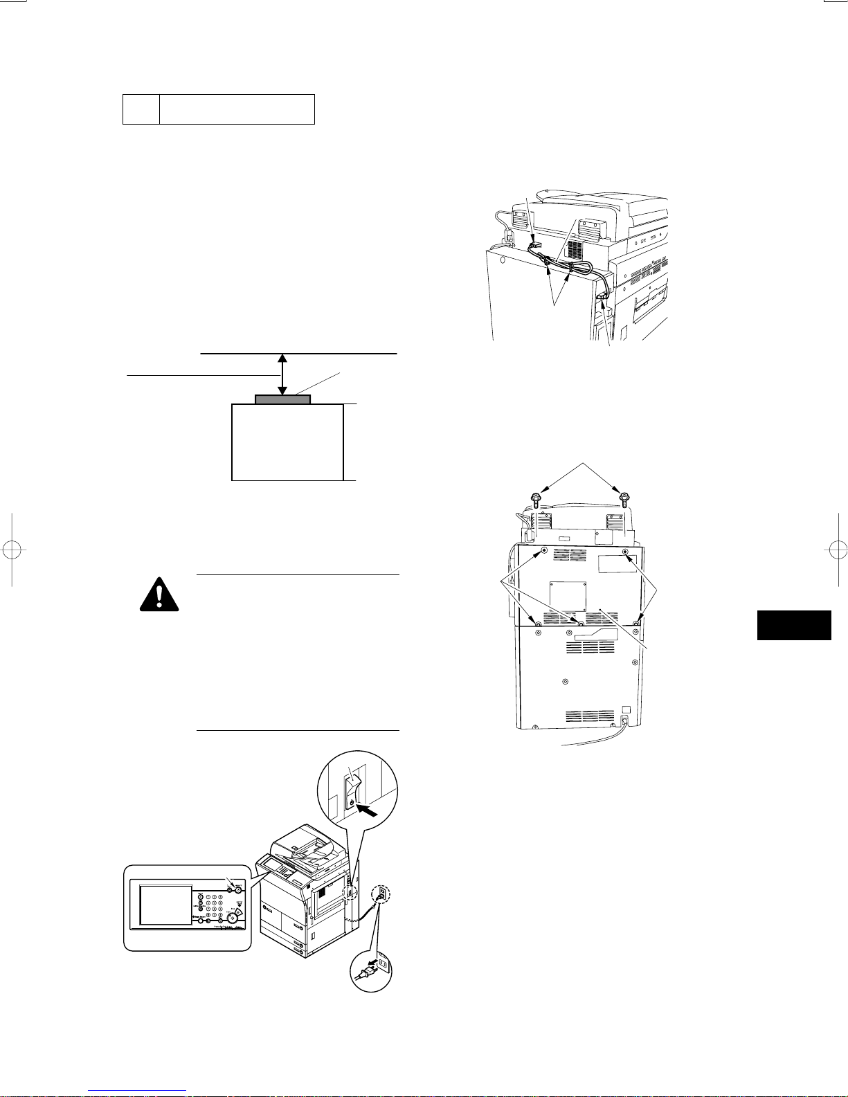
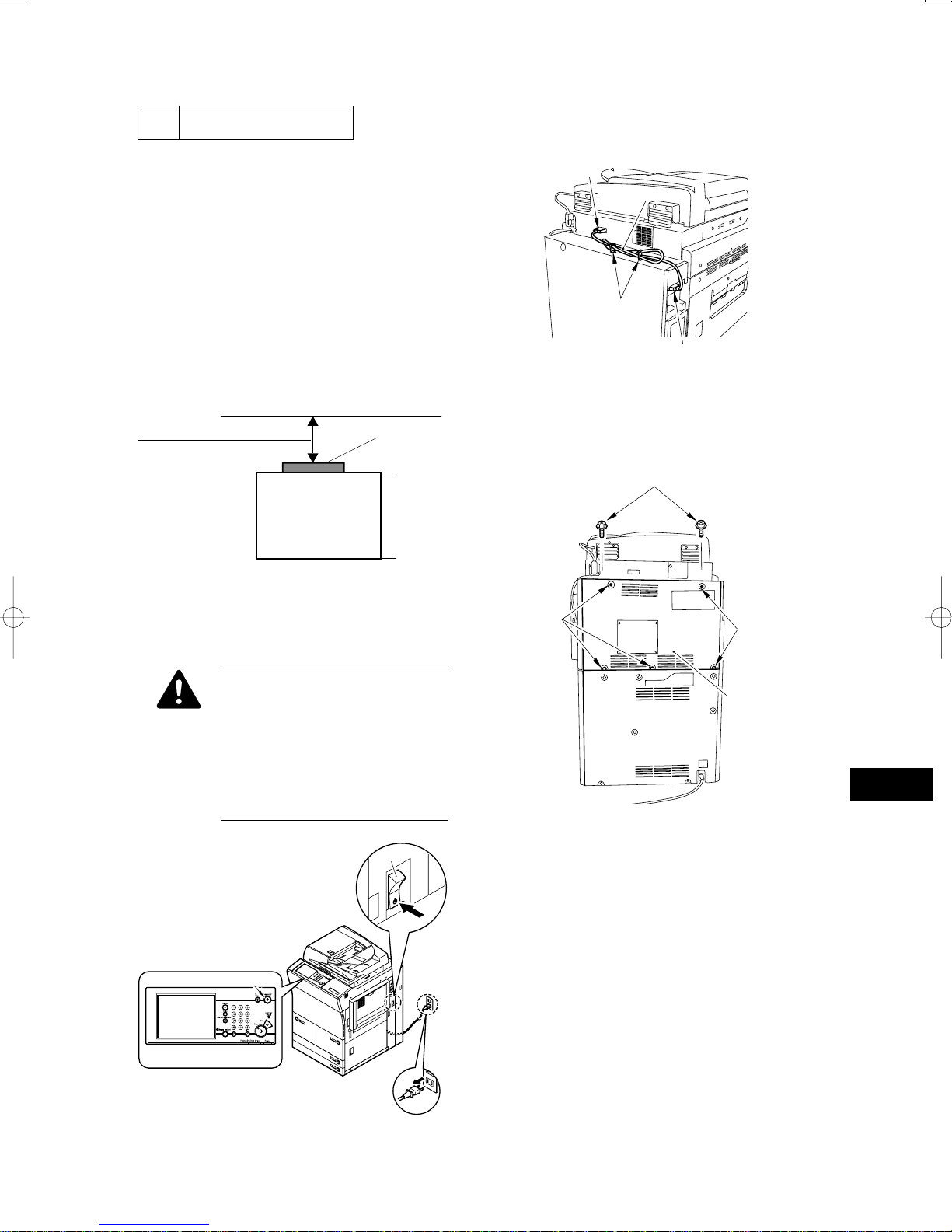
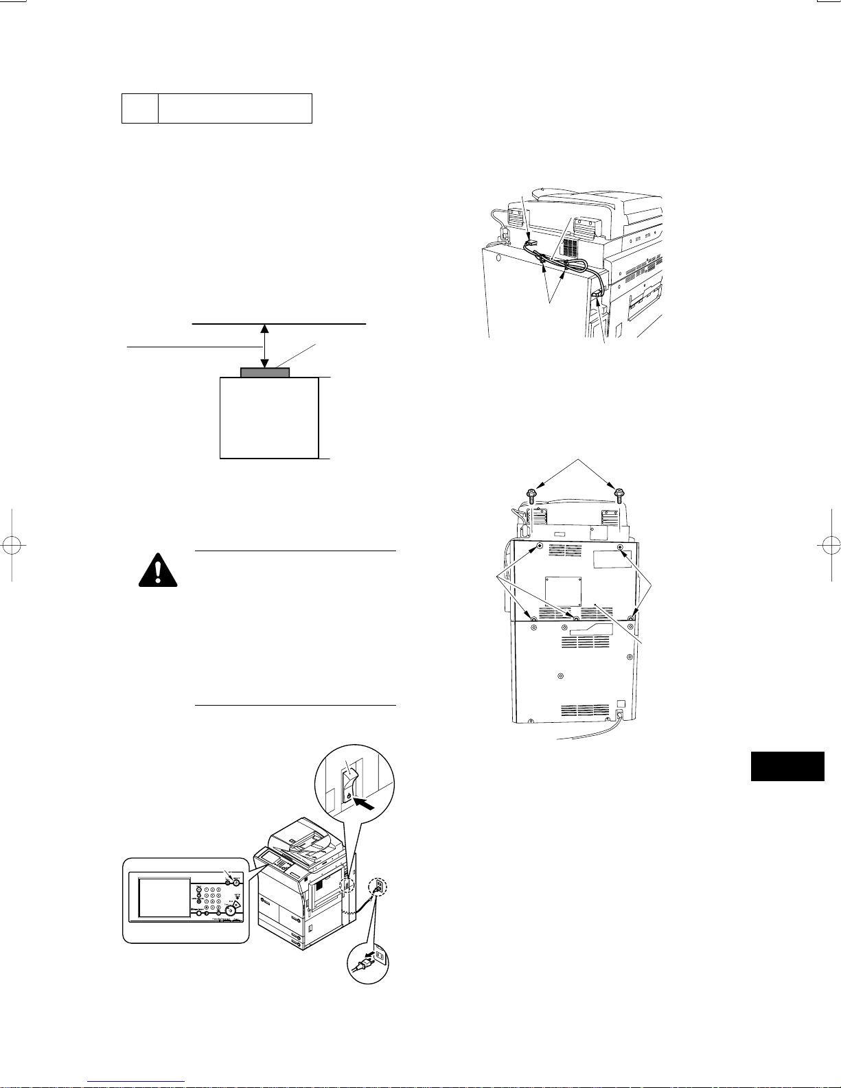
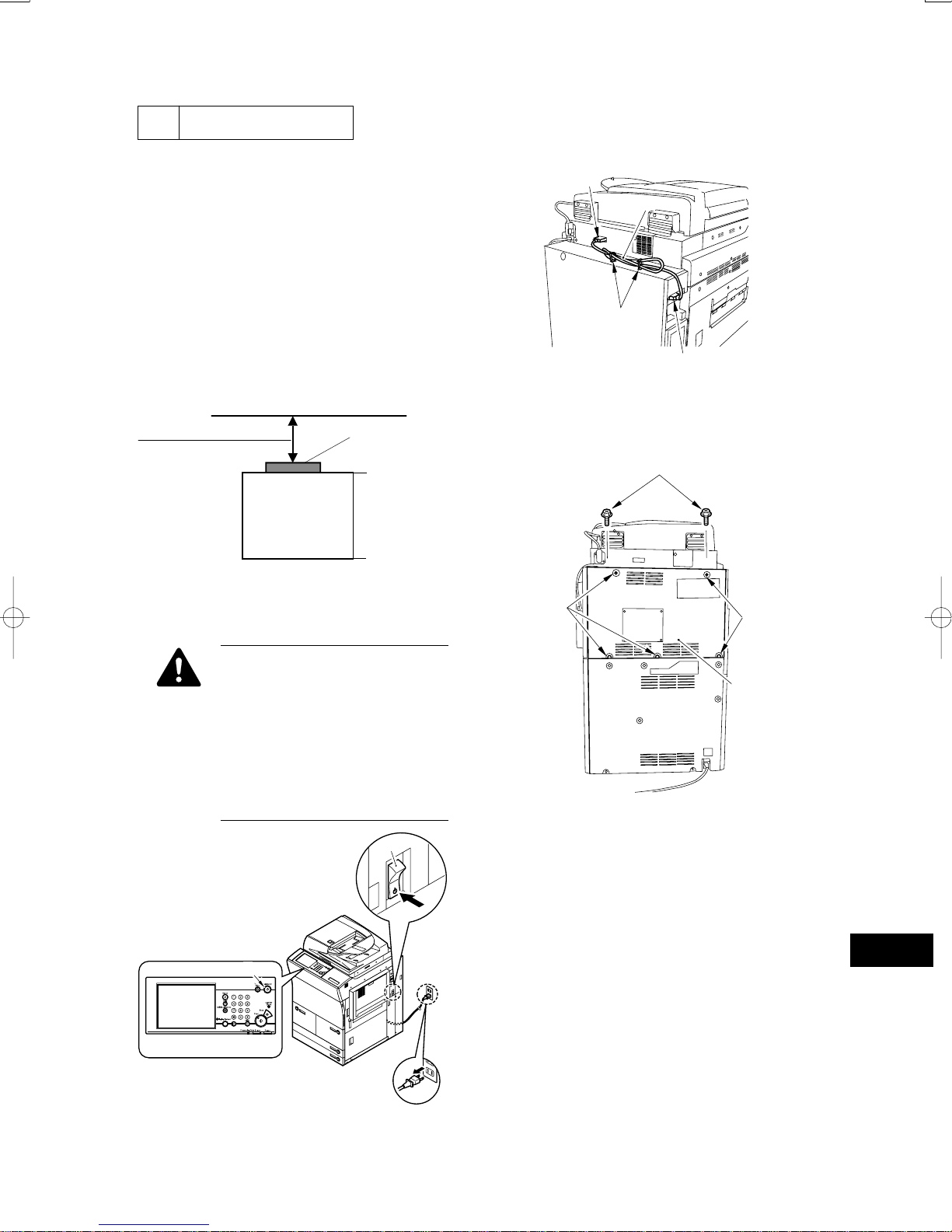
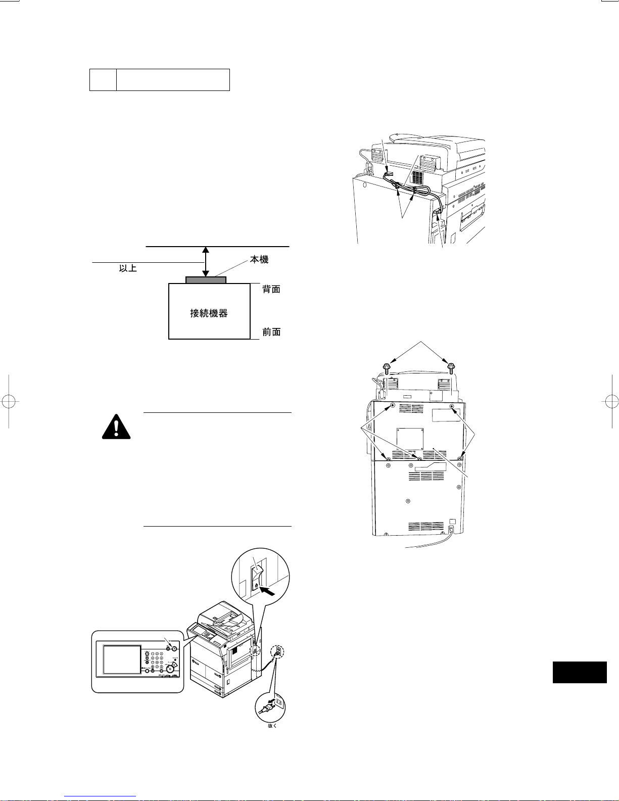
1) Open the cable clamp [1] of the host machine’s up-
per rear cover.
2) Disconnect the connector [2], and disconnect the
DDIS cable [3].
• Host Machine’s Service Mode
Make the following selections in service mode, and
set the item to ‘3’: COPIER>OPTION>INT-
FACE>IMAGE-CONT (so that the IP address used
for communication between host machine and the
server unit will automatically be set up).
• Make sure that the site of installation meets the fol-
lowing spatial requirements:
Machine
20 cm min.
(rear)
Host machine
(front)
Fig. 2-1
2.2 Installing to the Host Machine
Before stating the work, be sure to go
through the following in strict order on
the host machine:
1. turn off the control panel power
switch.
2. turn off the main power switch.
3. disconnect the power cable (of the
wall outlet).
[2]
[3]
[1]
[2]
Fig. 2-3
3) Remove the 7 screws [1], and detach the upper rear
cover [2].
[1]
[1]
[1]
[2]
[1]
OFF
Fig. 2-2
[2]
Fig. 2-4
OFF
[3] Disconnect
– 3 –
Page 4
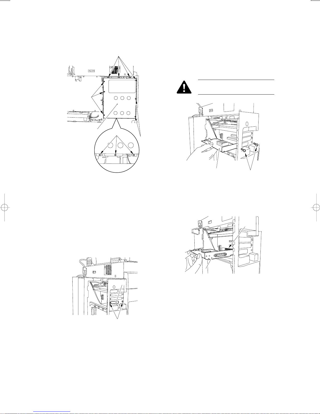
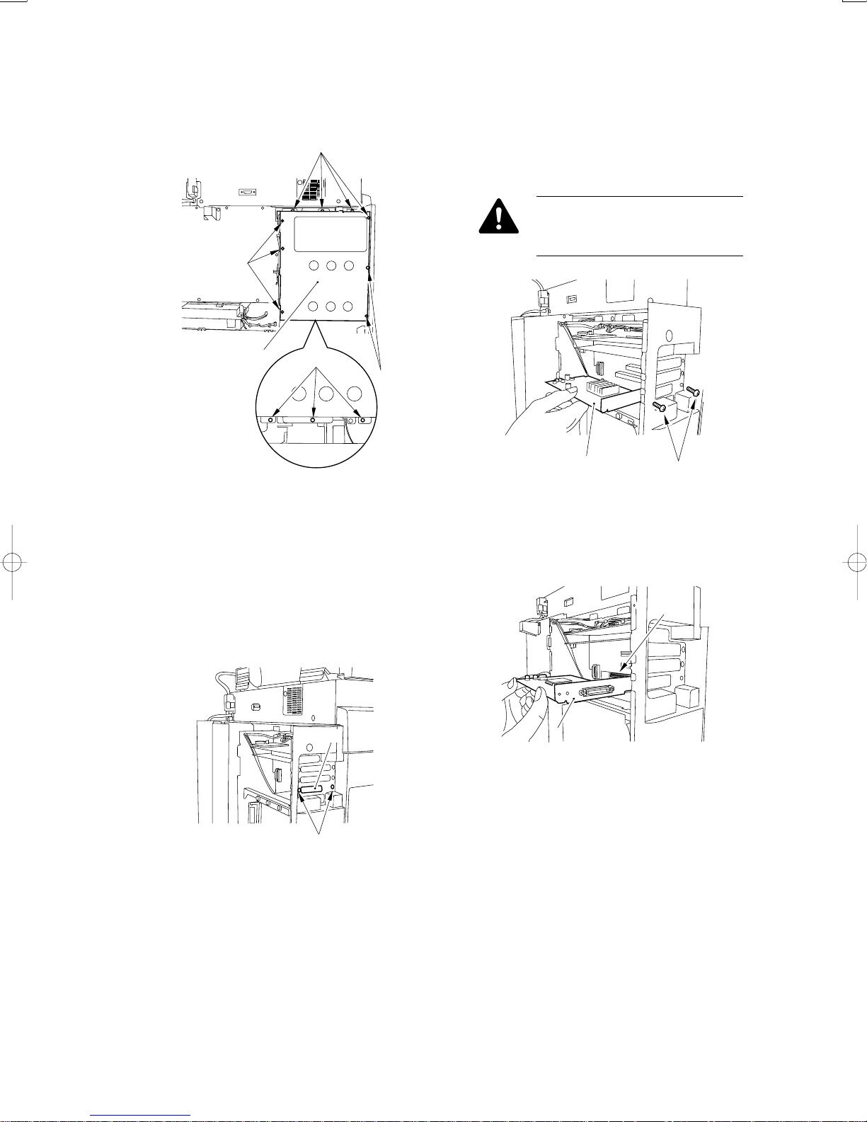
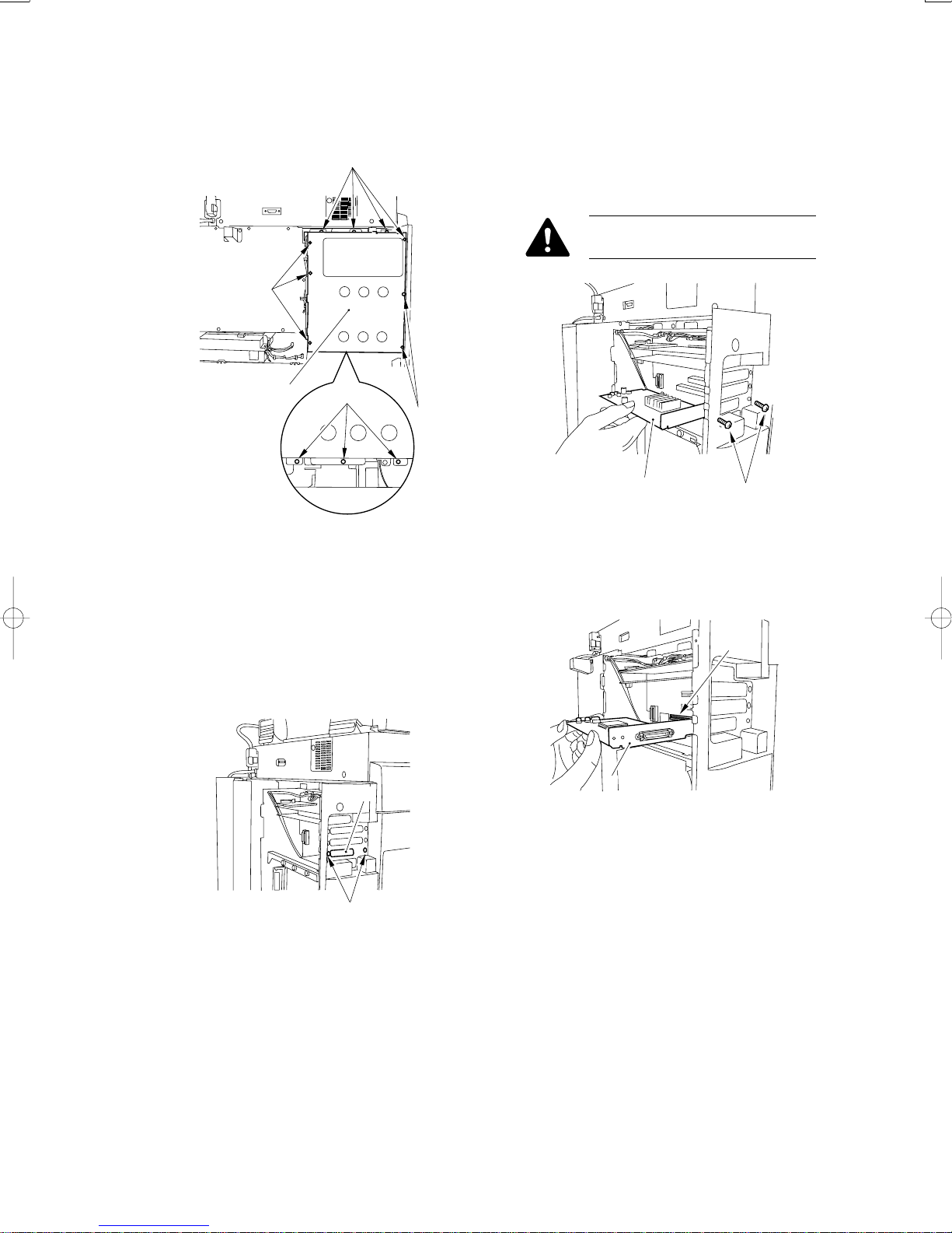
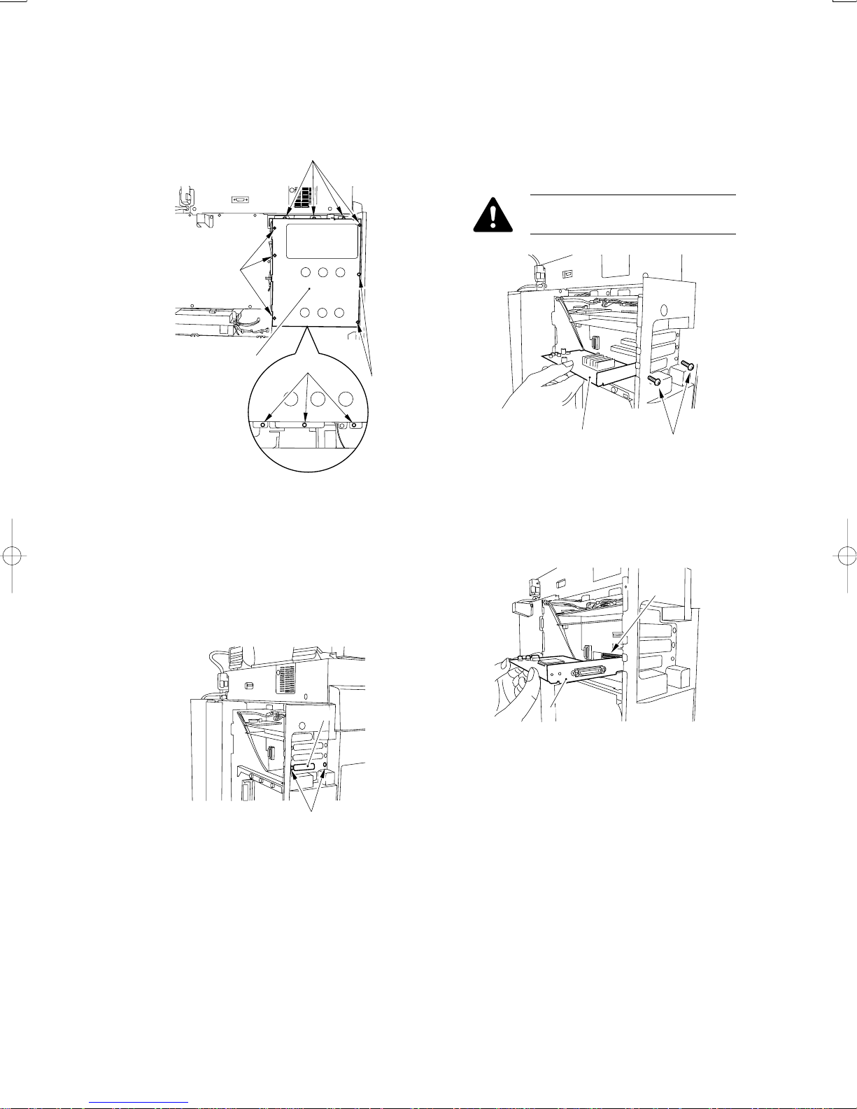
4) Remove the 12 screws [1], and detach the control-
ler box cover [2].
[1]
[1]
• If the Host Machine Is Equipped with a UFR Board
Remove the 2 screws [1], and detach the UFR board
[2]. (You will be using the removed screws [1] in the
next step.)
Hand over the removed UFR board to
the user for storage.
[2]
[1]
[1]
Fig. 2-5
5) Mount the open I/F PCB.
• If the Host Machine Is Not Equipped with a UFR
Board
Remove the 2 screws [1], and detach the face plate [2]
shown in the figure. (You will be using the removed
screws [1] in the next step.)
[2]
[2]
[1]
Fig. 2-7
6) Using the removed screws, mount the included open
I/F PCB [1] in the slot [2].
[2]
[1]
Fig. 2-8
Fig. 2-6
[1]
– 4 –
Page 5
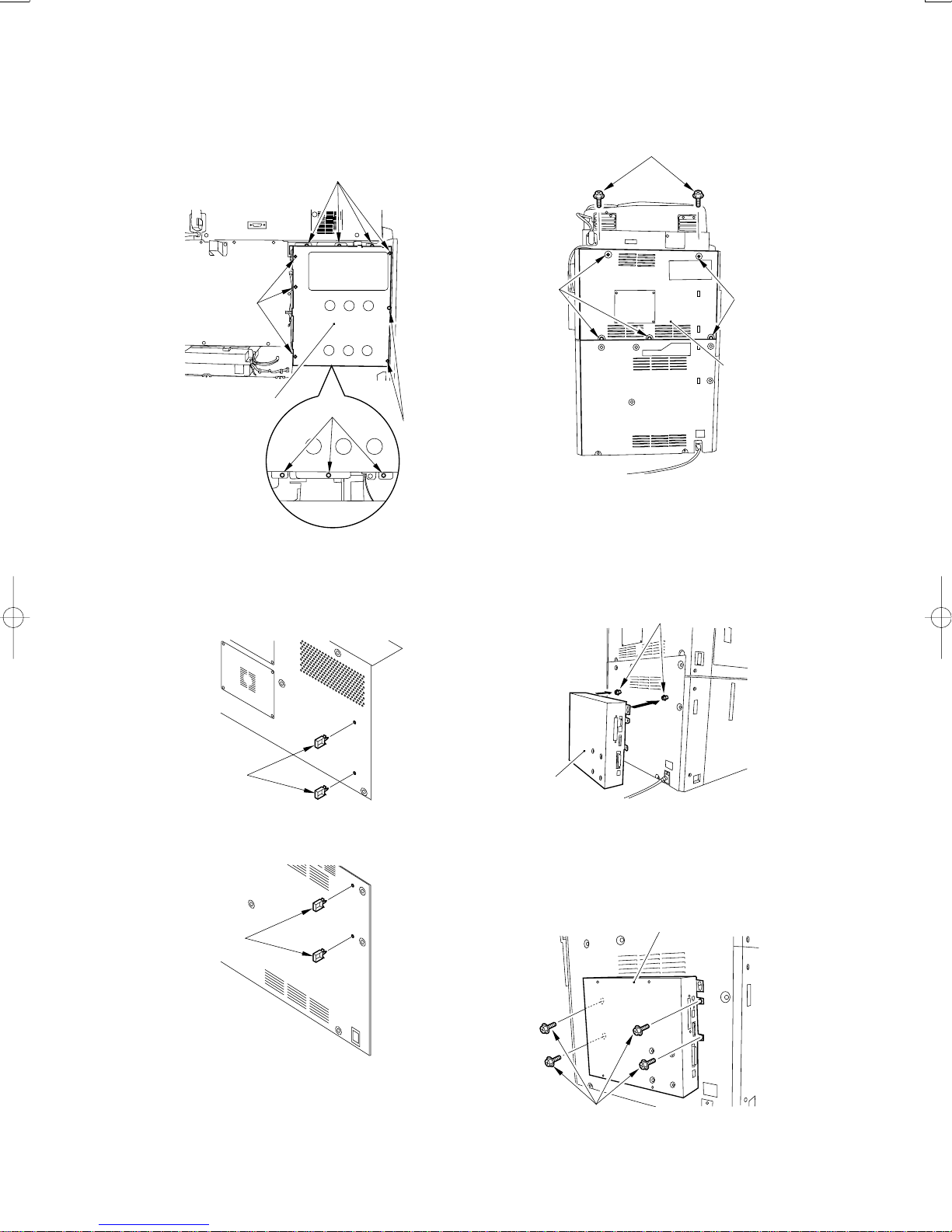
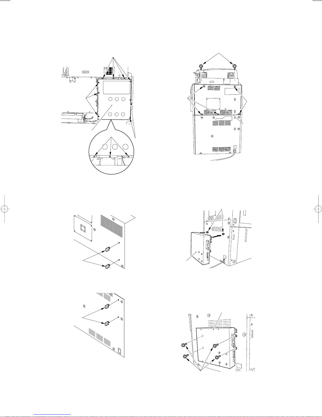
7) Mount the controller box cover [2] using 12 screws
[1].
[1]
9) Mount the upper rear cover using 7 screws [1].
[1]
[1]
[2]
[1]
[1]
Fig. 2-9
8) Fit the 2 cable clamps [1] each to the removed up-
per rear cover and the lower rear cover.
[1]
[1]
[2]
Fig. 2-11
10) Fit the included 2 stepped screws [1] to the lower
rear cover; then, hook the PS print server unit [2]
on the screws.
[1]
[1]
Fig. 2-10a
[1]
Fig. 2-10b
[2]
Fig. 2-12
11) Using the included 4 RS tightening screws [1] to
secure the PS print server unit [2] in place.
[2]
[1]
Fig. 2-13
– 5 –
Page 6
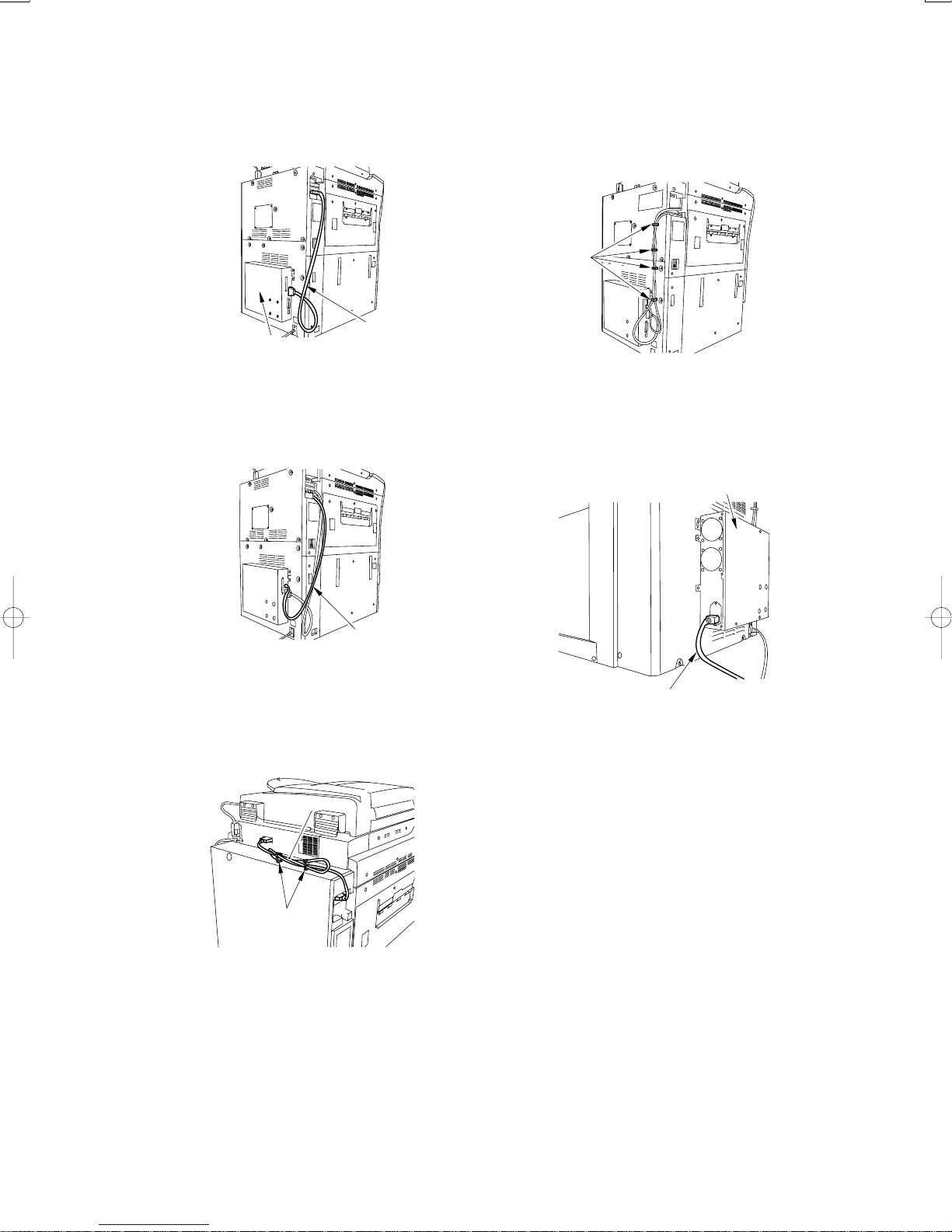
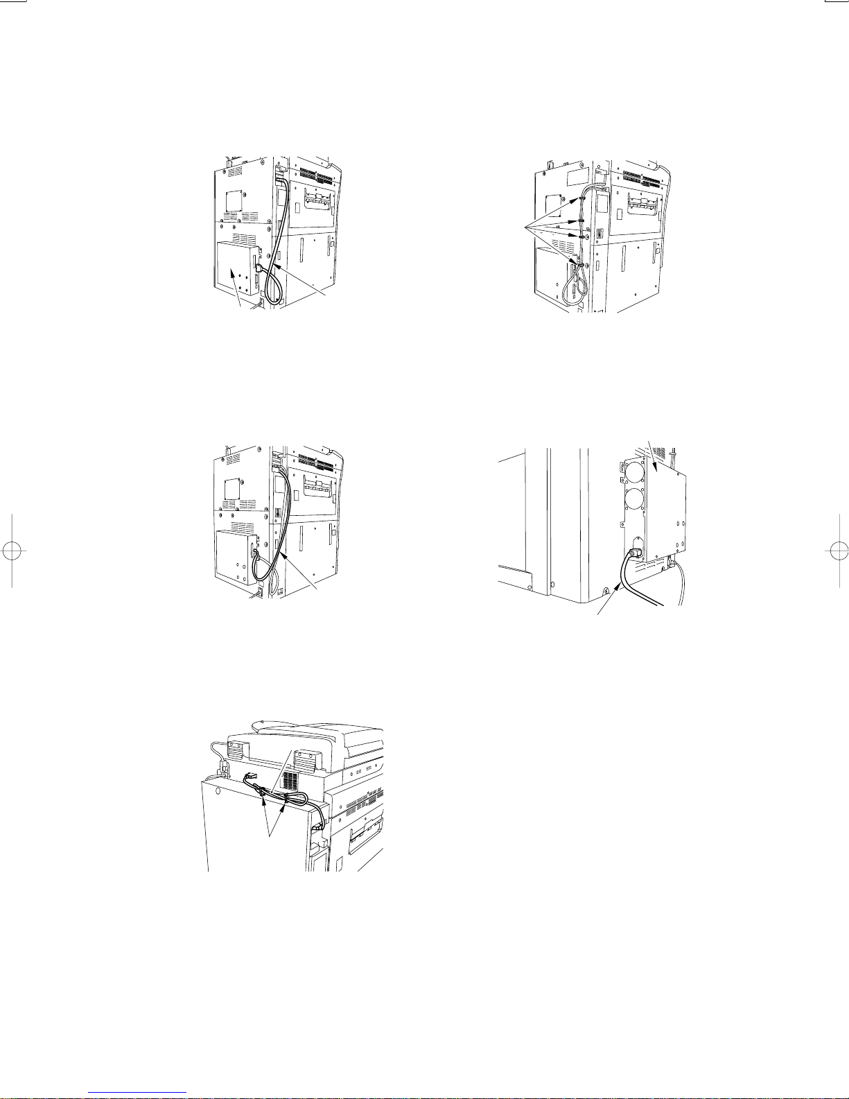
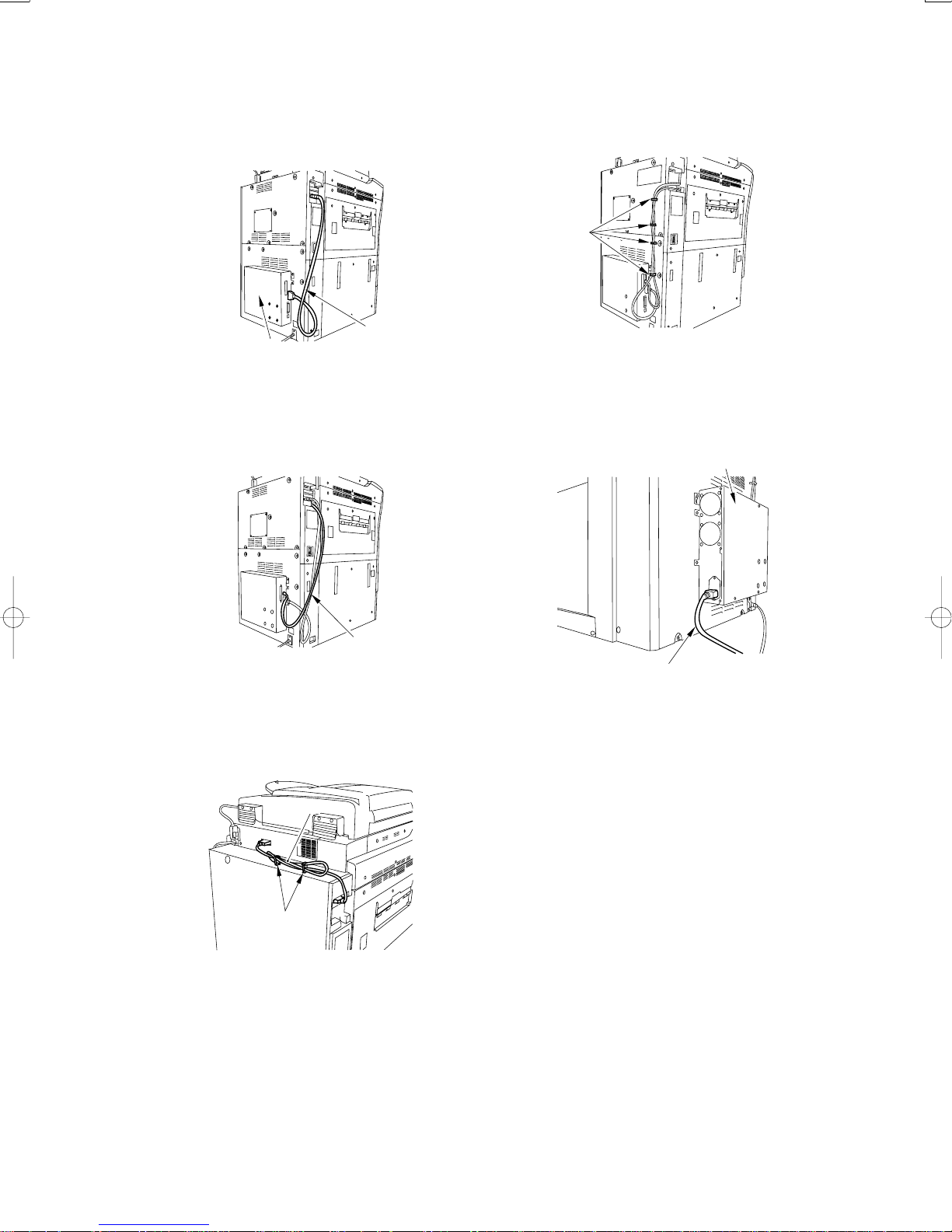
12) Using the communications cable [1], connect the
open I/F PCB and the PS print server unit [2].
15) Bundle the cross Ethernet cable and the commu-
nications cable using the 4 cable clamps [1] of the
host machine.
[1]
[2]
[1]
Fig. 2-14
13) Using the cross Ethernet cable [1], connect the
PS print server unit and the host machine.
[1]
Fig. 2-15
14) Connect the DDIS cable [1] to the server unit and
the reader unit; then, fix it in place using the 2 wire
saddles [2].
[1]
Fig. 2-17
16) Connect one end of the power cable [1] to the PS
print server unit [2] and the other end to the wall
outlet.
[2]
[1]
Fig. 2-18
17) Connect the host machine’s power cable (for the
wall outlet).
18) Turn on the host machine and the server unit.
[2]
Fig. 2-16
– 6 –
Page 7
2.3 Setting Up the Server Unit
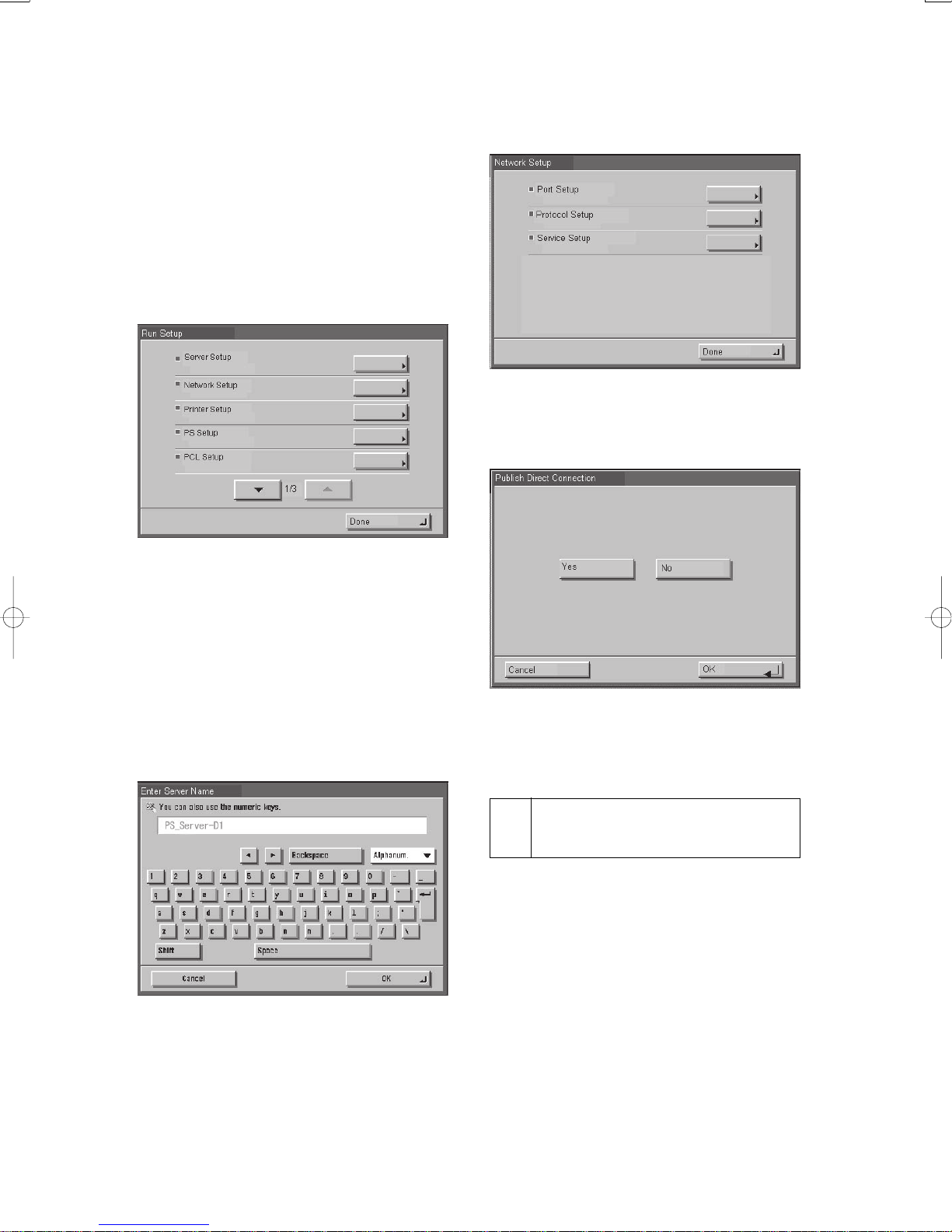
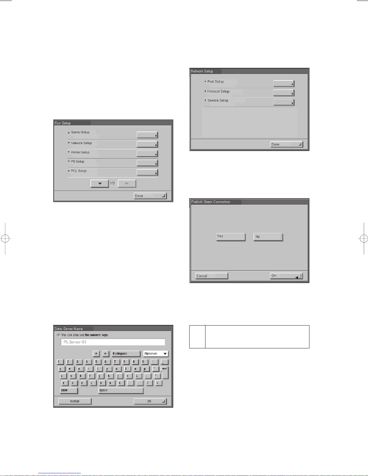
1) Press [Print] tab on the host machine’s control panel.
In case [Print] tab is not displayed, press [Print] tab
after press arrow tab.
2) Press [Printer status/Setting].
In response, the machine will automatically bring
up the Setup menu: select at least [Server Setup],
[Network Setup], and [Printer Setup] in order, stor-
ing appropriate data items as you move on.
Fig. 2-19
Network Setup:
Make port, protocol, and service settings.
Fig. 2-21
Printer Setup:
Make the print queue setting.
For instance, as you set up items under [Server Setup],
the machine will bring up a message asking if you
want to store the settings you have made; press [yes]
to store the settings. You will have to make the selec-
tions in specific order to move to subsequent items.
Server Setup:
Name the server, and make other settings.
Fig. 2-20
Fig. 2-22
3) Press [Done] under the Setup menu.
In response, the machine will automatically restart.
Checking the Operation After
3
Making Settings
Print out the test page and setup page as follows to
check that the connection between the server unit and
the host machine is correct and the server unit has prop-
erly been set up:
1) Press [Print] tab on the host machine’s control panel.
In case [Print] tab is not displayed, press [Print] tab
after press arrow tab.
2) Press [Printer status/Setting].
3)Make the following selections on the operation
panel: Functions>Print Pages>PS Test Page>and
Configuration.
– 7 –
Page 8
Module Imprimante Couleur reseau-D1
Procédure d’Installation
Suivre les instructions suivantes pour l’installation de Module Imprimante Couleur reseau-D1.
1 Description
[1] [2] [3] [4]
[5] [6] [7]
[1] Appareil ...................................................... 1 pc.
[2] Ouverture I/F PCB ...................................... 1 pc.
[3] Câble de connexion ................................... 1 pc.
[4] Câble de puissance (prise de courant) ........ 1 pc.
[8]
Fig. 1-1
[5] Câble de connexion Ethernet ...................... 1 pc.
[6] Serre-fil (angulaire) .................................... 4 pc.
[7] Vis à pas progressif ..................................... 2 pc.
[8] Vis de serrage RS (avec rondelle) ............... 4 pc.
– 8 –
Page 9
2 Installation
1) Déconnecter les 2 connecteurs [2] du câble DDIS.
2) Libérer le câble DDIS [3] du serre-fil [1].
2.1 Avant de commencer l’installation
• Sélectionner les options suivantes de l’unité
principale puis sélectionner « 3 » :
COPIEUR>OPTION>INTERFACE>
IMAGE-CONT. (De cette manière, l’adresse IP la
plus appropriée sera sélectionnée pour établir la
communication entre l’appareil et l’unité principale).
• S’assurer que l’arrière de l’appareil se situe à une
distance d’au moins 20 cm du mur, comme le décrit
la figure.
Appareil
20 cm min.
(arriere)
Unite principale
(avant)
Fig. 2-1
2.2 Installation de l’unité principale
[2]
[3]
[1]
[2]
Fig. 2-3
3) Enlever le couvercle arrière supérieur de la machine
[2]. (7 vis [1]).
[1]
[1]
[1]
Avant de commencer, effectuer les
opérations suivantes dans l’ordre
indiqué :
1. éteindre l’écran de contrôle.
2. éteindre l’appareil.
3. déconnecter le câble de puissance
(de la prise de courant).
[2]
OFF
[1]
OFF
[3] Disconnect
Fig. 2-2
[2]
Fig. 2-4
– 9 –
Page 10
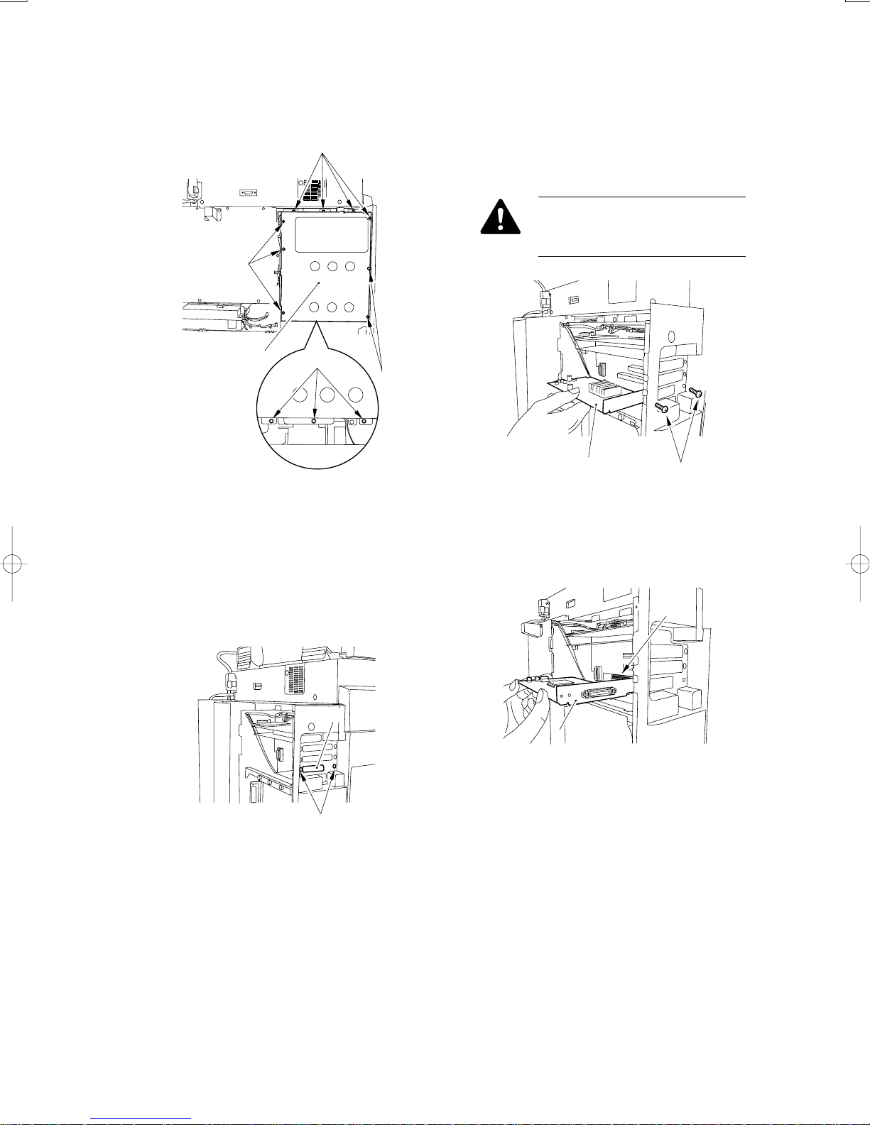
4) Oter les12 vis [1], et détacher le couvercle de la boîte
de contrôle [2].
[1]
[1]
• S’il existe un panneau UFR, ôter les 2 vis [1], puis
détacher le panneau UFR [2].
(Garder les vis ôtées [1] qui serviront dans un second temps).
Demander à l’utilisateur d’entreposer
le panneau UFR dans un endroit
approprié.
[2]
[1]
[1]
Fig. 2-5
5) Préparer le montage de l’ouverture I/F PCB
• S’il n’existe pas de panneau UFR, ôter les 2 vis [1],
puis détacher la plaque [2]. (Garder les vis ôtées [1]
qui serviront dans un second temps).
[2]
[2]
[1]
Fig. 2-7
6)En utilisant les vis ôtées auparavant, monter
l’ouverture I/F PCB [2].
[2]
[1]
Fig. 2-6
Fig. 2-8
[1]
– 10 –
Page 11
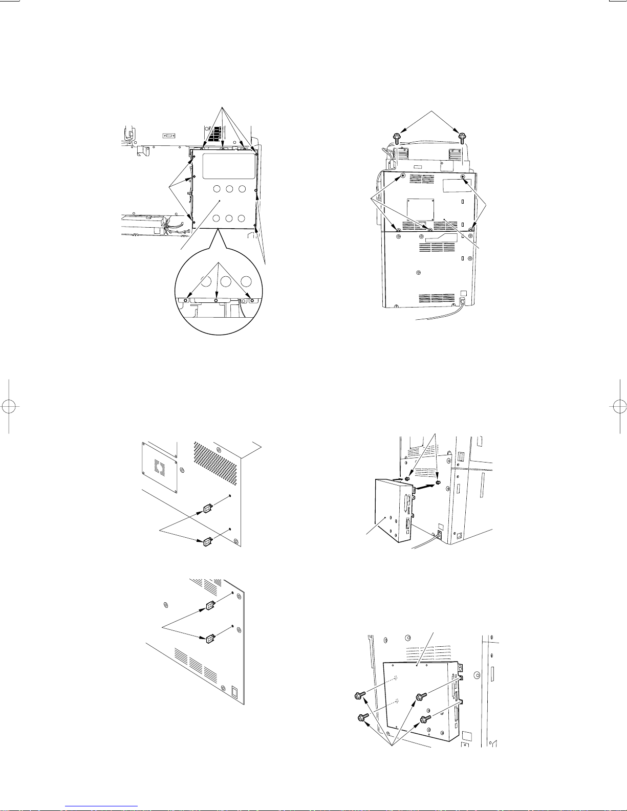
7) À l’aide des 12 vis monter le couvercle du boîtier
du contrôleur[1].
[1]
[1]
9)À l’aide des 7 vis monter le couvercle arrière
supérieur[2].
[1]
[1]
[1]
[2]
[1]
[1]
Fig. 2-9
8) Attacher les 2 serr-fils(angulaire)[1] chaque sur la
couvercle arrière supérieur et la couvercle arrière
inférieur
[1]
[2]
Fig. 2-11
10) Introduire les 2 vis à palier comprises dans
l’emballage [1] dans le couvercle arrière inférieur,
et y accrocher l’unité d’impression couleur en réseau
[2].
[1]
[2]
Fig. 2-10a
[1]
Fig. 2-10b
Fig. 2-12
11) À l’aide des 4 vis de serrage RS [1], fixer l’unité
d’impression couleur en réseau [2].
[2]
[1]
Fig. 2-13
– 11 –
Page 12
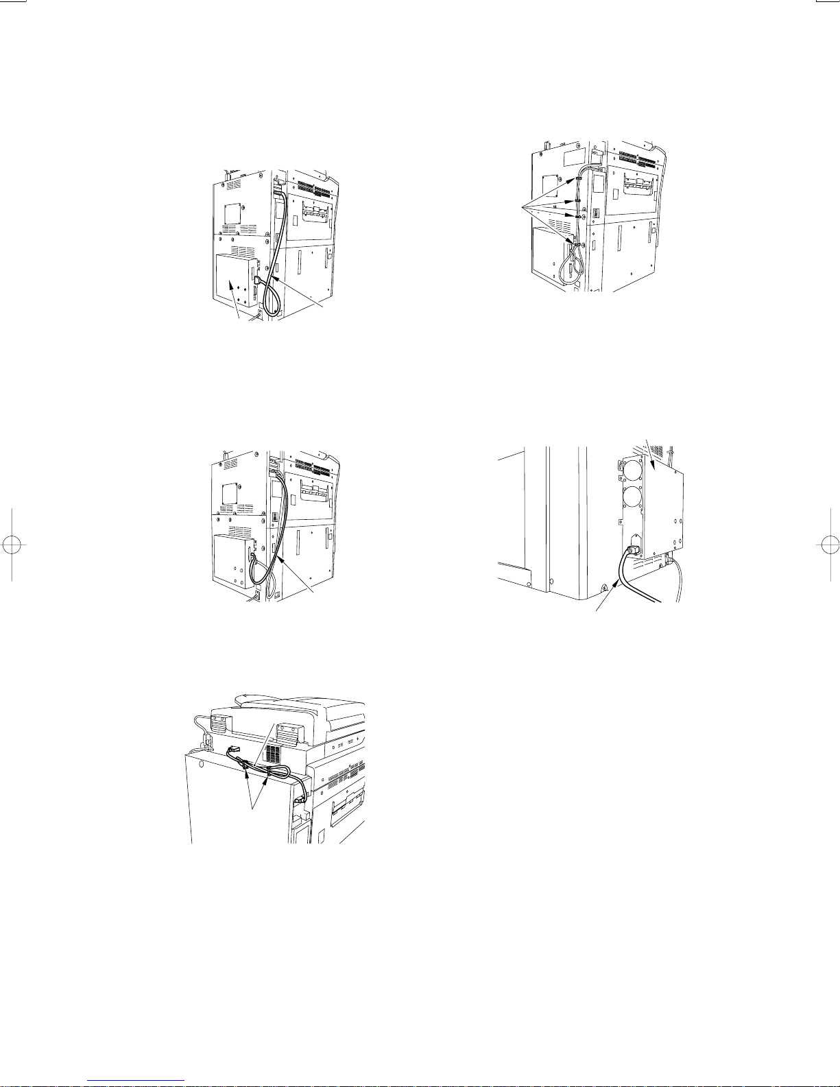
12) À l’aide du câble de communication [1], connecter le PCB I/F et l’unité d’impression couleur en
réseau.
15) Regrouper ensemble le câble de connexion
Ethernet et le câble de connexion.
[1]
[2]
[1]
Fig. 2-14
13) À l’aide du câble transversal Ethernet [1], connecter l’unité d’impression couleur en réseau à la
machine hôte.
[1]
Fig. 2-15
14) Connecter le câble DDIS [1].
[1]
Fig. 2-17
16) Connecter une extrémité du câble d’alimentation
(pour prise d’alimentation) [1] à l’unité d’impression
couleur en réseau, et l’autre extrémité à la prise
d’alimentation.
[2]
[1]
Fig. 2-18
17) Connecter le câble d’alimentation de la machine
hôte (pour prise d’alimentation).
18) Allumer la machine et sa machine hôte.
[2]
Fig. 2-16
– 12 –
Page 13
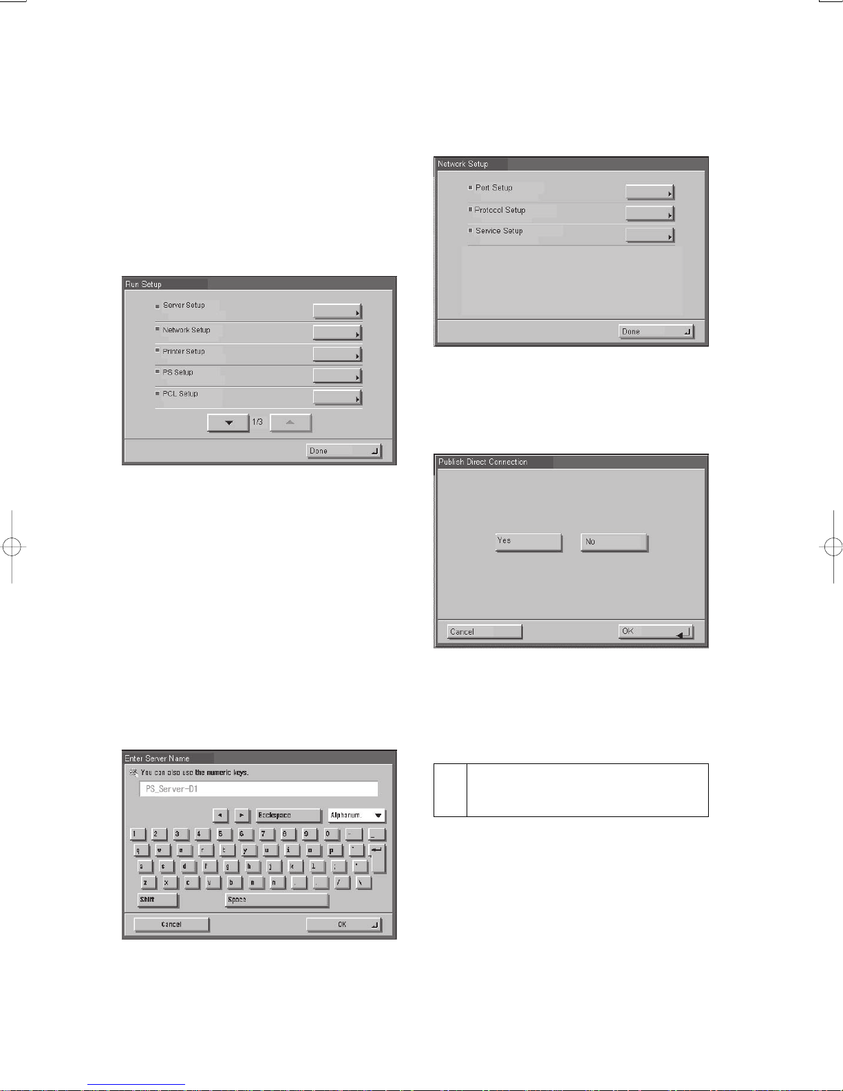
2.3 Mise au point de l’unité principale
1) Sur l’écran de contrôle, sélectionner [Edition] puis
appuyer sur la touche [Etat Edition/Options].
2)En guise de réponse, l’appareil montre
automatiquement le menu d’options. S’assurer que
toutes les options ont été correctement sélectionnées
dans l’ordre suivant: [installation serveur], [installation réseau], et [installation imprimante].
Fig. 2-19
Sélection des Options de Réseau:
Sélectionner les options appropriées telles que la
porte, le protocole et le service.
Fig. 2-21
Sélection des Options d’Edition:
Sélectionner les options appropriées telles que la
queue d’édition.
Par exemple, une fois que vous aurez sélectionné les
différentes options figurant au menu [installation
serveur], il vous sera demandé à l’écran si vous
souhaitez mémoriser les options choisies. Sélectionner
[oui] afin que le système mémorise ces données. Vous
ne pourrez passer à l’étape suivante qu’à condition
d’avoir sélectionné les options correctement , dans
l’ordre indiqué, et de les avoir mémorisé.
Sélection des options serveur:
Sélectionner les options correctement ainsi que le
nom du serveur.
Fig. 2-22
3)Sélectionner [arrêt] sur le menu de sélection. En
guise de réponse, le système se remet en marche
automatiquement.
Contrôle de l’Opération après
3
avoir sélectionné les Options
Editer une page de test ainsi qu’une page d’options de
la manière suivante afin de s’assurer d’une part que
toutes les options ont été correctement sélectionnées
et d’autre part que toutes les connexions ont été
correctement établies:
Fig. 2-20
1)Sur l’Ecran de Contrôle, sélectionner [Edition],
appuyer sur la touche [état édition/sélection].
2) Sélectionner les options suivantes sur l’écran LCD:
fonction>édition page>test page/options page.
– 13 –
Page 14
Farbdruckerkarte D1
Installationsverfahren
Beachten Sie bitte bei der Installation der Farbdruckerkarte D1 in die Hosteinheit die Anleitungen.
1 Prüfen Sie bitte die Bestandteile
[1] [2] [3] [4]
[5] [6] [7]
[1] Einheit ......................................................... 1 St.
[2] Offenes I/F PCB ........................................... 1 St.
[3] Verbindungskabel ........................................ 1 St.
[4] Stromkabel (für Stromausgang) .................. 1 St.
[8]
Abb. 1-1
[5] Cross-Ethernet-Kabel .................................. 1 St.
[6] Kabelklemme (Eckstück) ............................ 4 St.
[7] Gestufte Schraube ........................................ 2 St.
[8] RS-Befestigungsschraube (w/ washer) ........ 4 St.
– 14 –
Page 15
2 Installation
2.1 Bevor Sie mit der Arbeit beginnen
1) Oeffnen der Kabelklemme (1) an der oberen hinteren
Abdeckung der Maschine.
2) Ziehen Sie Stiftstecker [2] ab, und ziehen Sie Das
DDIS Kabel [3].
• Service Mode der Hosteinheit wie folgt einstellen
und auf ‘3’ einstellen:
COPIER>OPTION>INFACE>IMAGE-CONT. (So
wird automatisch die richtige IP Adresse für die
Verbindung zwischen dem Hauptgerät und dem.
• Sicherstellen, dass die Rückseite der Maschine
mindestens 20 cm von der Wand entfernt ist.
Maschine
20 cm min.
(Ruckansicht)
Hostgerat
(Vorderansicht)
Abb. 2-1
2.2 Installation des Hostgeräts
Bevor Sie mit der Arbeit beginnen,
müssen Sie das Hostgerät wie folgt
einstellen:
1. Den Strom der Bedientafel
absperren.
2. Den Hauptstrom absperren.
3. Das Stromkabel (Stromausgang)
abtrennen.
[2]
[3]
[1]
[2]
Abb. 2-3
3) Die 7 Schrauben [1] entfernen und die obere hintere
Abdeckung entfernen [2].
[1]
[1]
[1]
[2]
[1]
OFF
Abb. 2-2
[2]
Abb. 2-4
OFF
[3] Disconnect
– 15 –
Page 16
4)Die 12 Schrauben [1] entfernen und die
Abdeckung[2] entfernen .
[1]
[1]
• Wenn die Hostmaschine mit einer UFR - Karte
ausgestattet ist.
Entfernen Sie die 2 Schrauben (1), und nehmen Sie
die UFR - Karte (2) ab.
Beauftragen Sie den Benutzer, die
UFR - Karte an einem geeigneten Ort
aufzubewahren.
[2]
[1]
[1]
Abb. 2-5
5) Bereiten Sie die Installation der I/F PCB vor.
• Wenn die Hostmaschine nicht mit einer UFR - Karte
ausgestattet ist.
Entfernen Sie die 2 Schrauben (1) und nehmen Sie
die Planscheibe (2) ab. (Verwenden Sie die
entfernten Schrauben im nächsten Schritt).
[2]
[2]
[1]
Abb. 2-7
6) Benutzen Sie die entfernte Schraube, um die
beigelegte I/F PCB (1) einzubauen.
[2]
[1]
Abb. 2-6
Abb. 2-8
[1]
– 16 –
Page 17

7) Montieren Sie die Abdeckung der Kontrollbox[1].
9) Montieren Sie die obere hintere Abdeckung[1].
[1]
[1]
[2]
[1]
[1]
Abb. 2-9
8) Montieren Sie der 4 Kabelklemmen an der obere
hintere Abdeckung und untere hintere Abdeckung.
[1]
[1]
[1]
[2]
Abb. 2-11
10) Führen Sie die 2 beigelegten abgesetzten
Schrauben (1) in die untere hintere Abdeckung ein,
und haken Sie den Farbnetzwerkdrucker (2) in ihnen
ein.
[1]
[1]
[1]
Abb. 2-10a
Abb. 2-10b
[2]
Abb. 2-12
11) Benutzen Sie die 4 beigelegten RS –
Befestigungsschrauben (1), um den
Farbnetzwerkdrucker (2) vor Ort zu sichern.
[2]
[1]
Abb. 2-13
– 17 –
Page 18
12) Verwenden Sie das Kommunikationskabel (1), um
die I/F PCB und den Farbnetzwerkdrucker[2] zu
verbinden.
15) Bündeln Sie das Ethernetkabel und das
Kommunikationskabel mittels der 4 Kabelklemmen
(1) seitlich an der Hostmaschine.
[1]
[2]
[1]
Abb. 2-14
13) Verwenden Sie das gekreuzte Ethernetkabel (1),
um den Farbnetzwerkdruck mit der Hostmaschine
zu verbinden.
[1]
Abb. 2-15
14) Verwenden Sie das DDIS Kabel [1] und bündeln
Sie das Kabel der 2 Kabelklemmen [2].
[1]
Abb. 2-17
16) Verbinden Sie das Ende des Stromkabels (für die
Steckdose) (1) mit dem Farbnetzwerkdrucker und
das andere mit der Steckdose.
[2]
[1]
Abb. 2-18
17) Schließen Sie das Stromkabel der Hostmaschine
(für die Steckdose) an.
18) Schalten Sie die Maschine und die Hostmaschine
an.
[2]
Abb. 2-16
– 18 –
Page 19
2.3 Die Maschine einstellen
1) Auf der Kontrolltafel [Print] wählen und auf [Printer
Status/Settings]drücken.
2)Die Maschine zeigt automatisch das
Einstellungsmenü an. Mindestens folgende
Einstellungen wählen und die notwendigen
Einstellungen wie folgt einstellen: [set up server],
[set up network]und[set up printer]
Abb. 2-19
Netzeinstellungen:
Die notwendigen Einstellungen, mit Port, Protokoll
und Service einstellen.
Abb. 2-21
Druckereinstellungen:
Die notwendigen Einstellungen und die
Druckreihenfolge einstellen.
Z.b. wird nach den verschiedenen Einstellungen unter
(set up server) ein Bildschirm angezeigt der Sie fragt
ob die Einstellungen gespeichert werden sollen. (yes)
wählen, das System wird im Speicher gespeichert.
Wenn die notwendigen Einstellungen nicht in der
richtigen Reihenfolge erfolgen und gespeichert
werden, können Sie nicht zum nächsten Punkt
übergehen.
Servereinstellungen:
Die notwendigen Einstellungen und den
Servernamen einstellen.
Abb. 2-22
3) Im Menü Einstellungen [close] wählen. Der Start
des Systems erfolgt automatisch.
Die Funktion nach den erfolgten
3
Einstellungen
Erstellen Sie wie folgt eine Test- und Einstellungsseite,
und achten Sie darauf, dass Sie die richtigen
Einstellungen für die Mascchine und die Hostmaschine
durchageführt haben:
Abb. 2-20
1) Auf der Kontrolltafel [Print] wählen, dann auf Press
[PrinterStatus/Settings].
2)Auf dem LCD folgendes wählen: function>print
page>test page/settings page.
– 19 –
Page 20
Procedura di installazione
Per l’installazione dell’unità Color Network Printer Unit-D1 sulla copiatrice ospite, procedere come segue:
1 Controllo dei componenti
[1] [2] [3] [4]
[5] [6] [7]
[1] Unità ........................................................... 1 pz.
[2] Interfaccia PCB aperta ................................ 1 pz.
[3] Cavi di comunicazione ............................... 1 pz.
[4] Cavo Ethernet incrociato ............................ 1 pz.
[8]
Fig. 1-1
[5] Cavo Ethernet incrociato ............................ 1 pz.
[6] Morsetto per cavi (angolare)...................... 4 pz.
[7] Vite a gradini............................................... 2 pz.
[8] Morsettiera a vite RS (rondella washer) ..... 4 pz.
– 20 –
Page 21
2 Installazione
1) Rimuovere i 2 connettori [2] del cavo DDIS.
2) Estrarre il cavo DDIS [3] dal morsetto per cavi [1].
2.1 Prima di iniziare
• Selezionare le opzioni seguenti nel service mode
della macchina host, e scegliere “3”:
COPIER>OPTION>INFACE>IMAGE-CONT. (In
questo modo, l’indirizzo IP appropriato verrà
configurato automaticamente per consentire la
comunicazione tra la macchina e la macchina host
corrispondente.)
• Assicurarsi che il lato posteriore della macchina sia
distante almeno 20 cm dalla parete, come mostrato
in figura.
Macchina
20 cm min.
(lato posteriore)
Macchina host
(lato anteriore)
Fig. 2-1
2.2 Installazione su una macchina host
[2]
[3]
[1]
[2]
Fig. 2-3
3) Rimuovere il coperchio posteriore superiore [2] (7
viti [1]).
[1]
[1]
[1]
Prima di iniziare le operazioni,
eseguire correttamente le seguenti
istruzioni nell’ordine indicato:
1. Spostare su OFF l’interruttore del
pannello di controllo.
2. turn off the main power switch.
3. Spostare su OFF l’interruttore
principale.
[2]
OFF
[1]
OFF
[2]
Fig. 2-4
Fig. 2-2
[3] Disconnect
– 21 –
Page 22
4) Rimuovere le 12 viti [1], e distaccare la scatola del
controller [2].
[1]
[1]
• Se non è presente una scheda UFR, rimuovere le 2
viti [1], e distaccare la piastra della stampante [2].
(Conservare le viti rimosse [1] per le operazioni successive).
Chiedere all’utente di collocare la
scheda UFR in un luogo appropriato.
[2]
[1]
[1]
Fig. 2-5
5) Procedere al montaggio dell’interfaccia PCB aperta.
• Se non è presente una scheda UFR, rimuovere le 2
viti [1], e distaccare la piastra della stampante [2].
(Conservare le viti rimosse [1] per le operazioni successive).
[2]
[2]
[1]
Fig. 2-7
6)Utilizzando le viti rimosse precedentemente,
montare l’interfaccia PCB aperta in dotazione[2].
[2]
[1]
Fig. 2-8
Fig. 2-6
[1]
– 22 –
Page 23
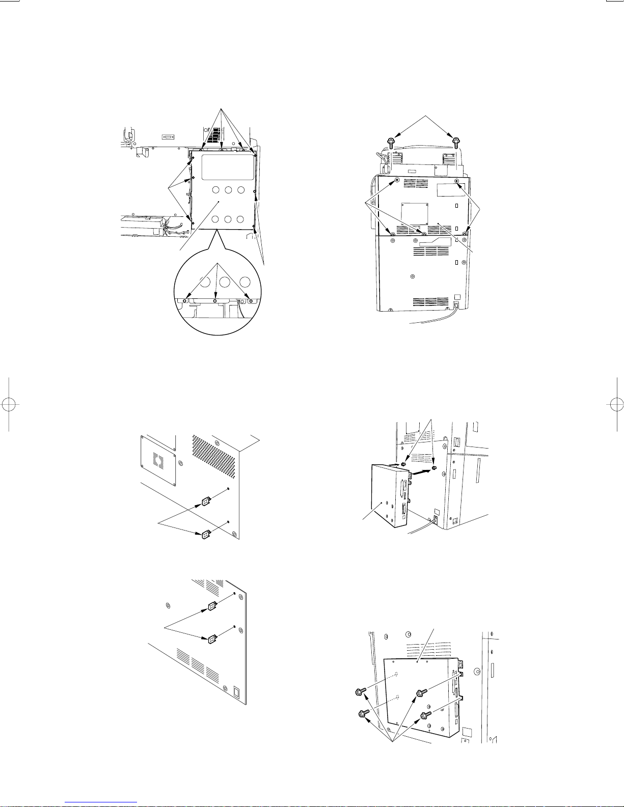
7) Utilizzando 12 viti[1], montare la scatola del controller[2].
[1]
[1]
9)Utilizzando 7 viti[1], assemblare il supporto di
montaggio [2] al supporto posteriore
[1]
[1]
[1]
[2]
[1]
[1]
Fig. 2-9
8) Attaccare 2 fermacavo(tipo angolare) [1] ogni sull
coporchio posteriore superiore e sull coperchio
posteriore inferiore.
[1]
[2]
Fig. 2-11
10) Montare sul coperchio posteriore inferiore le due
viti a gradino [1] fornite e agganciare ad esse la
Color Network Printer Unit [2].
[1]
[2]
Fig. 2-10a
[1]
Fig. 2-10b
Fig. 2-12
11) Utilizzando le 4 viti di fissaggio RS fornite [1],
fissare in posizione la Color Network Printer Unit
[2].
[2]
[1]
Fig. 2-13
– 23 –
Page 24
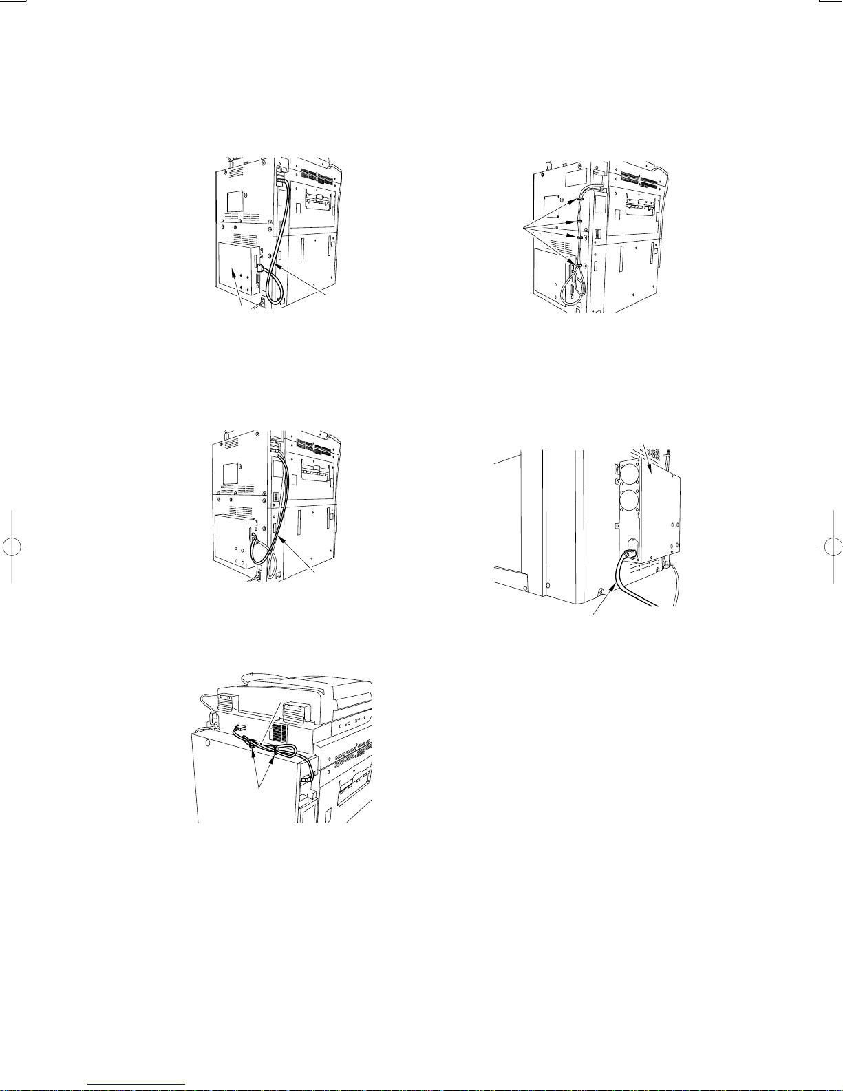
12) Utilizzando il cavo di comunicazione [1],
collegare la scheda di interfaccia alla Color Network
Printer Unit.
15) Utilizzando il morsetto per can de la macchina
host, fissare insieme il cavo Ethernet e i can di
communicazione.
[1]
[2]
[1]
Fig. 2-14
13) Usando il cavo incrociato Ethernet [1], collegare
la Color Network Printer Unit alla macchina ospite.
[1]
Fig. 2-15
14) Collegare il cavo di DDIS [1] all’uniti.
[1]
Fig. 2-17
16) Collegare un’estremità del cavo di alimentazione
(per presa elettrica) [1] all’unità e collegare l’altra
estremità alla presa elettrica.
[2]
[1]
Fig. 2-18
17) Collegare il cavo di alimentazione (per presa
elettrica) della macchina host.
18) Accendere la macchina host e la macchina.
[2]
Fig. 2-16
– 24 –
Page 25
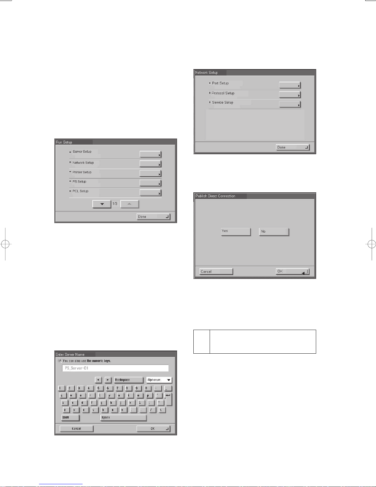
2.3 Configurare la macchina
1)Sul Pannello di Controllo, selezionare “Stampa”
[Print] quindi premere “Stato stampante/
Impostazioni” [Printer Status/Settings].
2)Il sistema mostrerà automaticamente il menu
“Impostazioni” [Settings]. Seguire correttamente le
istruzioni e configurare le impostazioni appropriate
nel seguente ordine: “Configurare server” [set up
server], “Configurare rete” [set up network] e
“Configurare stampante” [set up printer].
Network Setup:
Effettuare le impostazioni correttamente, indicando
anche porta di accesso, protocollo e servizio.
Fig. 2-21
Printer Setup:
Consente eseguire le impostazioni relative alla coda
di stampa.
Fig. 2-19
Ad esempio, dopo avere configurato le varie
impostazioni tramite “Configurare server” [set up
server], sullo schermo apparirà una videata con la
richiesta di memorizzazione delle impostazioni.
Selezionare “SI” [yes] per permettere al sistema di
memorizzare i dati. È necessario avere configurato le
impostazioni appropriate nel corretto ordine e averle
salvate per poter procedere al prossimo passaggio.
Server Setup:
Effettuare le impostazioni correttamente, indicando
anche il nome del server.
Fig. 2-20
Fig. 2-22
3)Selezionare “Chiudi” [close] nel menu
“Impostazioni”. Il sistema si riavvierà
automaticamente.
Controllare le operazioni dopo
3
avere configurato le impostazioni
Stampare una pagina di prova e la pagina delle
impostazioni come indicato dalle istruzioni seguenti per
verificare che tutte le impostazioni siano state effettuate
correttamente sia sulla macchina che sulla macchina host
corrispondente, e che tutti i collegamenti siano regolari:
1)Sul Pannello di Controllo, selezionare “Stampa”
[Print], premere “Stato stampante/impostazioni”
[Printer status/Settings].
2) ullo schermo LCD selezionare di seguito:
“Funzione” [function] > “Stampa pagina” [print
page] > “Pagina di prova/pagina delle impostazioni”
[test page/settings page].
– 25 –
Page 26
PSプリントサーバユニット・D1
設置手順書
PSプリントサーバユニット・D1を接続機器に取り付ける際は、この手順に従って下さい。
1 同梱部品の確認
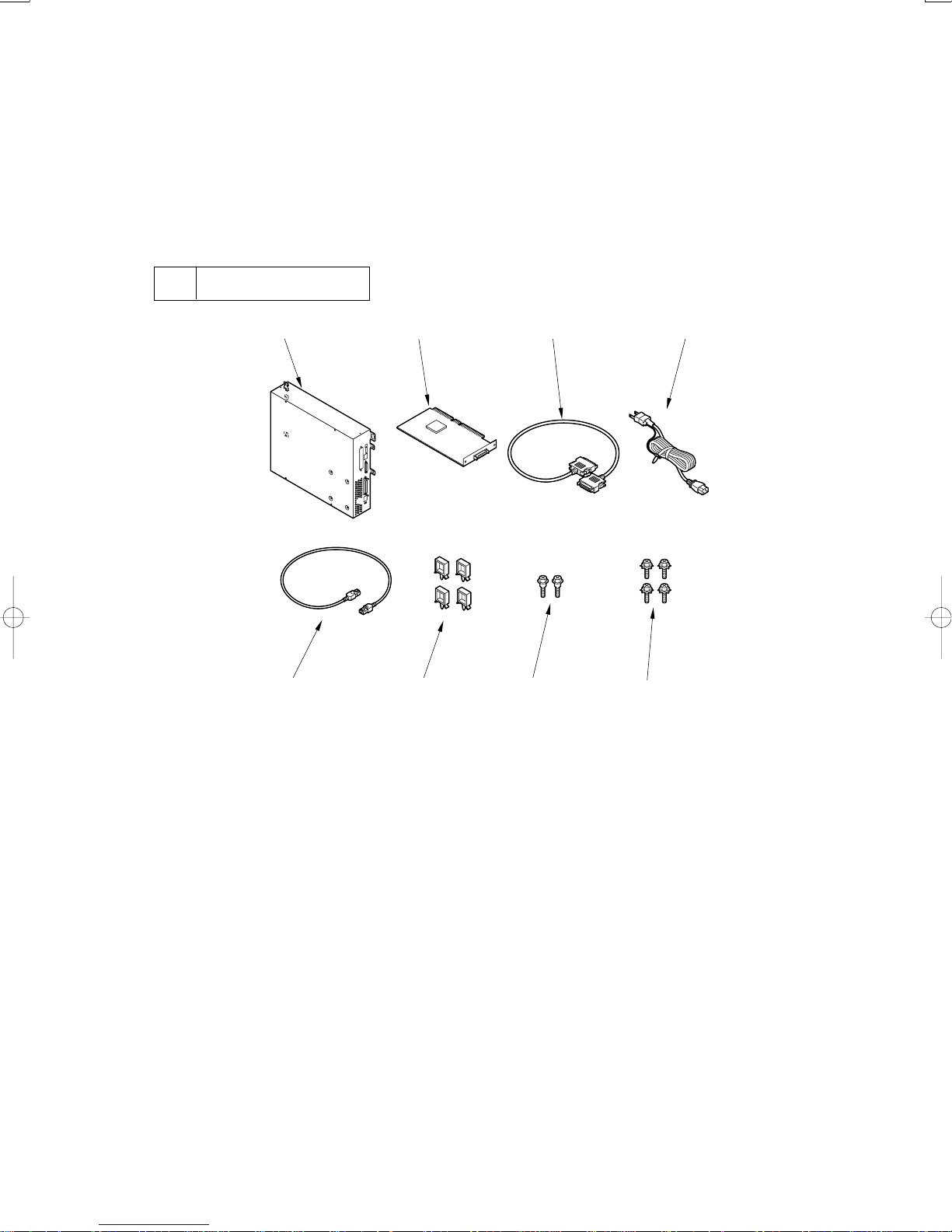
[1] [2] [3] [4]
[5] [6] [7]
[1]PSプリントサーバユニット ........... 1個
[2] オープンI/F回路基板 ................ 1個
[3] 通信ケーブル ....................... 1個
[4] 電源ケーブル ....................... 1個
[8]
図1-1
[5] クロスイーサネットケーブル ......... 1個
[6] ケーブルクランプ ................... 4個
[7] 段ビス ............................. 2本
[8] RSタイトビス(菊座付) ............. 4本
– 26 –
Page 27
2 設置手順
2.1 設置前の準備
■接続機器のサービスモード
COPIER>OPTION>INT-FACE>IMG-CONTを「3」に設定
しておくこと。(接続機器と本機間の通信用IP
アドレスを自動で設定するモード)
■下図のように本機を設置するスペースを確保す
る。本機の背面から20cm以上のスペースが必要
である。
20 cm
図2-1
1)本体後上カバーのケーブルクランプ[1]を開
く。
2)コネクタ[2]を抜き、DDISケーブル[3]を外
す。
[2]
[3]
[1]
[2]
図2-3
3)ビス[1]7本を外し、後上カバー[2]を取り外
す。
[1]
2.2 接続機器への取り付け
設置する前に、必ず接続機器側で
下記の作業を順番通りに行うこ
と。
1. 操作部電源スイッチをOFFす
る。
2. 主電源スイッチをOFFする。
3. 電源ケーブル(コンセント用)を
抜く。
[1]
OFF
ON/OFF
/
[1]
[2]
[1]
[2]
図2-4
OFF
図2-2
[3]
– 27 –
Page 28
4)ビス[1]12本を外し、コントローラボックス
カバー[2]を取り外す。
[1]
[1]
■本体にUFRボードが設置されている場合
ビス[1]2本を外して、UFRボード[2]を取り外
す。(取り外したビス[1]は次の手順で使用す
る)
取り外したUFRボードはユーザに渡
し、保管して頂くこと。
[2]
[1]
[1]
図2-5
5)オープンI/F回路基板の取り付け手順を行
う。
■本体にUFRボードが設置されていない場合
ビス[1]2本を外して、図に示す目隠し板[2]を
取り外す。(取り外したビス[1]は次の手順で使
用する)
[2]
[2]
[1]
図2-7
6)外したビスを使用して、同梱のオープンI/F
回路基板[1]をスロット[2]に取り付ける。
[2]
[1]
図2-8
図2-6
[1]
– 28 –
Page 29
7)コントロールボックスカバー[2]をビス12本
[1]で取り付ける。
[1]
9)後上カバーをビス[1]7本で取り付ける。
[1]
[1]
[2]
[1]
[1]
図2-9
8)外した後上カバー、後下カバーにそれぞれ
ケーブルクランプ[1]を2個取り付ける。
[1]
[1]
[2]
図2-11
10)同梱の段ビス[1]2本を後下カバーに取り付
け、PSプリントサーバユニット[2]を掛ける。
[1]
[1]
図2-10a
[1]
図2-10b
[2]
図2-12
11)同梱のRSタイトビス[1]4本で、PSプリント
サーバユニット[2]を固定する。
[2]
[1]
図2-13
– 29 –
Page 30
12)通信ケーブル[1]で、オープンI/F回路基板と
PSプリントサーバユニット[2]を接続する。
15)クロスイーサネットケーブル、通信ケーブル
を本体側のケーブルクランプ[1]4個で束ねる。
[1]
[2]
[1]
図2-14
13)クロスイーサネットケーブル[1]で、PSプリ
ントサーバユニットと接続機器とを接続する。
[1]
図2-15
14)DDISケーブル[1]をプリンタ部及びリーダ部
に接続し、ワイヤサドル[2]2個で固定する。
[1]
図2-17
16)電源ケーブル[1]の一方をPSプリントサーバ
ユニット[2]に、もう一方をコンセントに接続
する。
[2]
[1]
図2-18
17)接続機器の電源ケーブル(コンセント用)を接
続する。
18)接続機器と本機の電源をONにする。
[2]
図2-16
– 30 –
Page 31
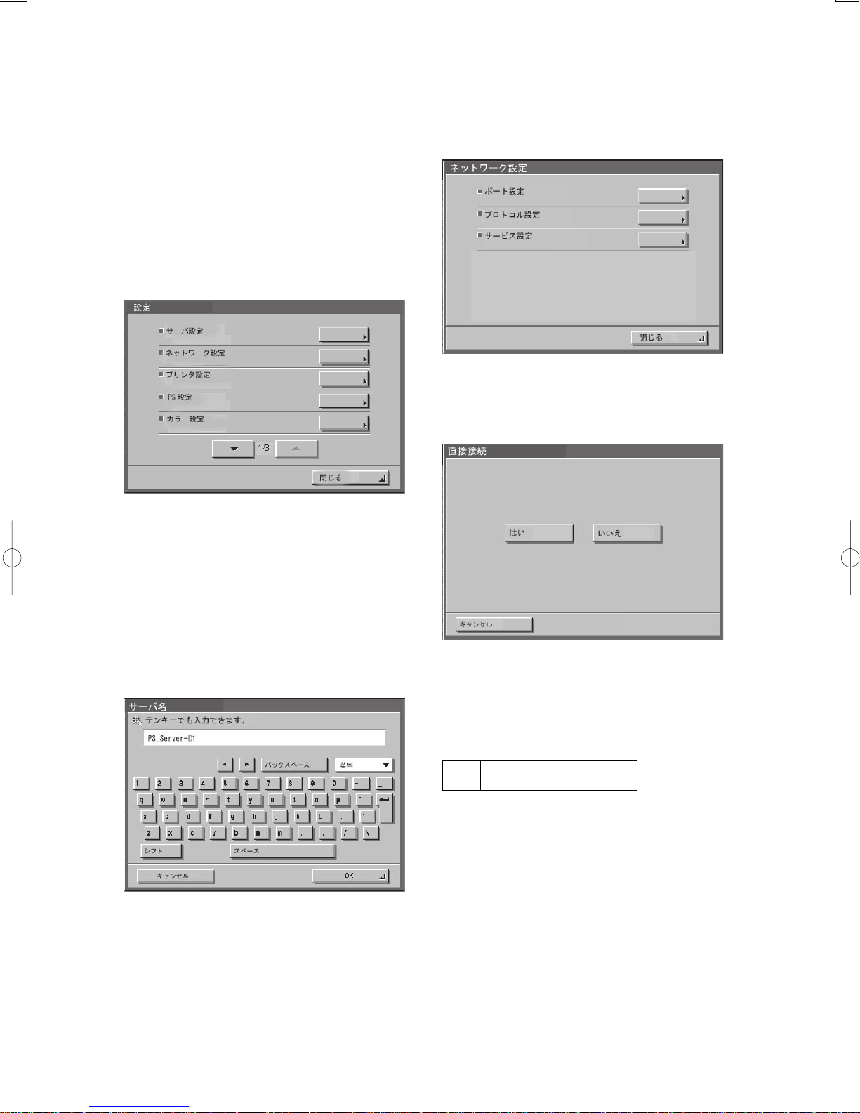
2.3 本機の設定
1)接続機器の液晶表示部上の「プリンタ」タブを
押す。「プリンタ」タブが表示さえていない場合
は、矢印「⇒」タブを押した後、「プリンタ」タブ
を押す。
2)「プリンタ状況/設定」ボタンを押す。
その後、自動的に「設定」メニューに入るので、
最低「サーバ設定」、「ネットワーク設定」、「プ
リンタ設定」の各項目を順番に選択し、各々
データを保存する。
図2-19
ネットワーク設定:
ポート設定、プロトコル設定、サービス設定を
行う。
図2-21
プリンタ設定:
印刷キューの設定を行う。
例えば、「サーバ設定」の各項目を設定していく
と、最後に変更の保存をするかどうかを選択する
画面が表示されるので、「はい」を選択すると、そ
の時の設定を保存することができる。各項目を順
番に選択して保存しないと次の項目を設定できな
い。
サーバ設定:
サーバ名の設定等を行う。
図2-20
図2-22
3) 「設定」メニューの「閉じる」を選択する。
その後、自動的に再起動が行われる。
3 設定後の動作確認
以下の手順で、テストページ、設定ページを出力
し、接続機器と本機の接続および本機の設定を確
認する。
1)接続機器の液晶表示部上の「プリンタ」タブを
押す。「プリンタ」タブが表示さえていない場合
は、矢印「⇒」タブを押した後、「プリンタ」タブ
を押す。
2)「プリンタ状況/設定」ボタンを押す。
3)液晶表示部上の「機能」-「ページの印刷」-「テ
ストページ」および「設定ページ」を選択する。
– 31 –
Page 32

PUB. F-IM-6262-010 PRINTED IN JAPAN/IMPRIME AU JAPON
 Loading...